| Title | Size | Downloads |
|---|---|---|
| H3C UIS Manager Site Recovery Management Configuration Guide-5W101-book.pdf | 1.31 MB |
- Table of Contents
- Related Documents
-
H3C UIS Manager
Site Recovery Management Configuration Guide
Document version: 5W101-20210809
Copyright © 2021 New H3C Technologies Co., Ltd. All rights reserved.
No part of this manual may be reproduced or transmitted in any form or by any means without prior written consent of New H3C Technologies Co., Ltd.
Except for the trademarks of New H3C Technologies Co., Ltd., any trademarks that may be mentioned in this document are the property of their respective owners.
The information in this document is subject to change without notice.
Contents
Key metrics for disaster recovery performance measurement
About UIS site recovery management
Cost-effective disaster recovery plan
One-stop disaster recovery solution
Support for various disaster recovery scenarios
UIS disaster recovery configuration procedure
Configuring storage disaster recovery
Configuring storage disaster recovery
Creating an asynchronous replication pair
Adding SRAs for the local and remote sites
Configuring a protection group
About disaster recovery
Disaster recovery recovers data and resumes service operations for information systems from faults or breakdowns caused by natural disasters and infrastructure failures such as fires, floods, earthquakes, power outages, and network egress failures.
Typically, a disaster recovery system contains two or more identical service systems deployed at geographically dispersed sites. The disaster recovery system monitors the service systems and maintains data consistency among them. When one service system fails, its services fail over to another site to ensure service continuity.
Key metrics for disaster recovery performance measurement
The following metrics are used for measuring the performance of a disaster recovery system:
· Recovery point objective (RPO)—The maximum acceptable amount of data loss measured in time. It refers to a period of time in which services must be restored and recovered. RPO is used to measure the data loss caused by a disaster and to evaluate the data backup capability of a disaster recovery system. Typically RPO depends on how data is replicated. Synchronous replication can guarantee an RPO of zero, which indicates no data loss. In asynchronous replication, RPO is determined by the replication cycle.
Figure 1 RPO

· Recovery time objective (RTO)—The maximum tolerable length of time that a service system can be down after a failure or disaster. It defines how long it takes to restore services to running state. RTO is used to measure the data restoration capability of a disaster recovery system. It is determined by the service restoration procedure in disaster recovery. The more automated the restoration steps, the smaller the RTO.
Figure 2 RTO

Types of disaster recovery
Based on the level of protection, the following types of disaster recovery are available:
· Data-level disaster recovery—Replicates data among disaster recovery sites at different locations to avoid data loss or damage in the event of a disaster. To one site, the other sites are remote data backup centers.
· Application-level disaster recovery—Maintains an identical application system at a backup site for failed important applications to fail over to the backup site after a disaster as soon as possible. It enables application systems to offer complete, reliable, and secure services to users.
Array-based replication
Disaster recovery relies on array-based replication to back up and protect data. Array-based replication copies all or some data sets of an application from a host disk or storage array to another storage medium to prevent misoperations or failures from causing data loss. Array-based replication can be performed synchronously or asynchronously.
Synchronous replication
Synchronous replication ensures data consistency between the storage volumes in a replication pair. In synchronous replication, each IO operation releases resources only after both the local and remote volumes in a replication pair return write operation completion. Synchronous replication provides the highest level of data integrity at the cost of decreased performance caused by data transmission latency, and it requires the round trip delay between source and destination arrays to be short. Typically, synchronous replication is used for short-distance replication (10 to 100 km, or 6.21 to 62.13 miles) in scenarios that require strict data consistency and near-zero data loss, such as internal systems of banks.
Figure 3 Synchronous replication

Asynchronous replication
Asynchronous replication is performed periodically and thus cannot ensure data consistency between volumes in a replication pair. In asynchronous replication, a local volume creates a snapshot after it finishes a write operation and copies the snapshot to a remote volume. Asynchronous replication offers high performance but does not guarantee zero data loss because source and destination volumes might have inconsistent data. Asynchronous replication does not require high bandwidth or short transmission distance, which makes it suitable for systems that require high performance, have light write loads, and does not require high array IOPS performance or short delay, such as databases and file systems.
Figure 4 Asynchronous replication

About UIS site recovery management
UIS site recovery management (SRM) provides disaster recovery services for applications based on array-based replication.
Application scenarios
UIS SRM is applicable to data centers in homogeneous clouds (with same H3C UIS version deployed). UIS SRM can decrease RPO and RTO to minutes and replicate data for storage arrays regardless of whether they support storage replication adapters (SRAs).
|
|
NOTE: SRAs enable SRM to discover storage systems, replicate LUNs, and test and perform disaster recovery. When SRM tests disaster recovery, runs scheduled recovery, or runs failure recovery, SRAs offer resources to SRM and cooperate with SRM in disaster recovery automation in a virtualization environment. |
Configuration environment
· UIS edition—UIS Enhanced Enterprise Edition with SRM licensed.
· Storage arrays—HP storage arrays that support remote replication.
· Storage automation—ONEStor or MacroSAN.
Mechanisms
UIS SRM ensures data consistency and service continuity as follows:
· At the storage level, SRM backs up data through asynchronous replication between storage arrays.
· At the service level, SRM copies configuration of protected VMs from a protected site to a recovery site in each protection group.
When the protected site fails, SRM restores protected VMs at the recovery site by using the data backed up at the storage and service levels based on a recovery plan.
Figure 5 Storage replication and disaster recovery procedure

Features
Cost-effective disaster recovery plan
SRM relies on distributed storage replication to copy data of protected VMs at the storage level and decreases RPO and RTO to minutes. SRM allows a pair of sites to back up each other to protect user investments.
SRM supports both ONEStor and storage arrays that support storage replication and snapshots. If storage arrays do not support SRAs, you must manually prepare the storage environment before failing over services.
Automated disaster recovery
SRM synchronizes VM configuration changes from a protected site to a recovery site in time and allows you to simulate disaster recovery on schedule to ensure availability of the disaster recovery system. Replicating protected VM data at the storage level, SRM reduces the impacts of disaster recovery services on server performance.
One-stop disaster recovery solution
SRM offers a disaster recovery solution that includes both storage configuration and disaster recovery task configuration. You can directly configure compute, storage, and network resource mappings for the protected and recovery sites.
SRM allows unified management of the protected and recovery sites. It can synchronize the disaster recovery configuration on the recovery site with the protected site. You do not need to configure SRM on multiple consoles.
Support for various disaster recovery scenarios
SRM allows you to simulate disaster recovery without interrupting running services. This mechanism can help you achieve the expected recovery target and decrease RTO. You also can fail over services from a recovery site to a protected site, enable SRM to run recovery as scheduled, and manually fail over services to the recovery site.
UIS disaster recovery configuration procedure
Figure 6 Configuration procedure

Configuring sites
Configure a protected site and a recovery site (local and remote sites, respectively). After you configure storage disaster recovery, add SRAs for the sites and synchronize asynchronous replication pairs between block devices.
Configuring storage disaster recovery
To implement storage disaster recovery, you must create asynchronous replication pairs, which are mappings between block devices (LUNs) at the protected and recovery sites. The block devices synchronize data based on data synchronization policies over the links established between the address pools at the sites. The link set is known as a remote device.
Figure 7 Configuring storage disaster recovery

Configuring SRM
To configure SRM, perform the following steps:
1. Assign VMs attached to the same storage pool (one or multiple LUNs in storage arrays) to a protection group, and create mappings between vSwitches, port profiles, and storage at the protected and recovery sites.
2. Configure a recovery plan for the protection group.
Figure 8 SRM
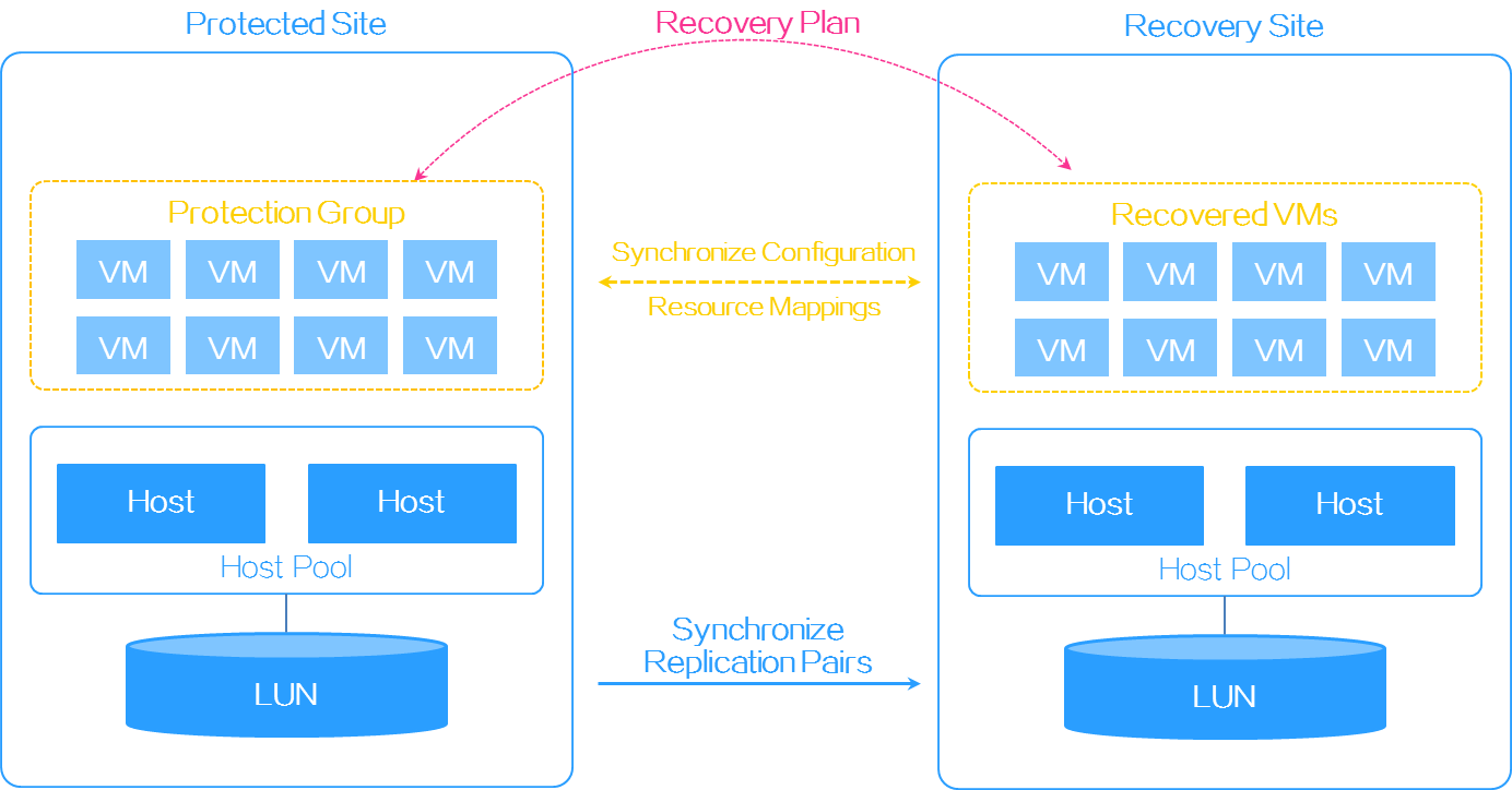
For array-based replication to operate correctly, make sure the following requirements are met:
· The protected and recovery sites use the same replication technology.
· Storage replication and snapshot features have been licensed on storage arrays.
Disaster recovery scenarios
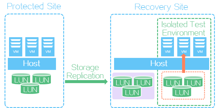
Recovery plan test
SRM allows you to test whether a recovery plan operates correctly by failing over VMs based on the recovery plan to an isolated test environment at the recovery site without interrupting services. In a recovery plan test, VMs are attached to the LUNs at the recovery site. You must manually finish a recovery plan test to clear the environment and restore the state of the recovery plan to Ready.
Figure 9 Recovery plan test
Scheduled recovery
A scheduled recovery shuts down VMs at the protected site and resumes them at the recovery site on schedule for regular maintenance of the protected site. A scheduled recovery triggers a data replication. SRM resumes VMs at the recovery site only after it finishes copying all protected data to the recovery site.
In a heterogeneous environment, SRM does not shut down protected VMs. You must manually shut down them at the protected site.
Figure 10 Scheduled recovery

Failure recovery
Failure recovery restores VMs at the recovery site based on a recover plan to reduce the service interruption time when the protected site fails.
Figure 11 Failure recovery

Reverse recovery
Reverse recovery falls back VMs from a recovery site to a protected site when the protected site recovers from failure.
Figure 12 Reverse recovery

Configuring disaster recovery
Restrictions and guidelines
· You must perform a full storage data replication before the first scheduled recovery.
· You can specify any network for data replication on hosts (replication nodes). As a best practice, use a dedicated replication network.
· Make sure the block devices meet the following requirements:
¡ The block devices at the protected and recovery sites must have the same capacity.
¡ Block devices in a thick-provisioned disk pool do not support recovery plan test because ONEStor does not support snapshots for thick-provisioned disk pools. As a best practice, use thin-provisioned data pools.
¡ If the block devices do not support SRAs, you must first mount them as shared file systems at the recovery site. If you mount the block devices to hosts, SRM skips storage replication when running a recovery plan.
Network planning
As shown in Figure 13:
· Deploy two UIS systems with converged deployment.
· Deploy CVK and ONEStor at the protected and recovery sites.
· Use Server #1 as a management and service node.
· Deploy four CVK hosts at the protected site and two CVK hosts at the recovery site.
· Set up dedicated management and replication networks.

Adding sites
SRM provides service recovery across different sites (data centers). With SRM, you can configure the local UIS Manager as the protected site, and configure a recovery site for the protected site. When the protected site stops providing services, the recovery site can take over to guarantee uninterrupted services.
|
|
NOTE: · Configure a local site and a remote site on either the protected site or recovery site. The sites will synchronize the configuration. · You do not need to configure SRAs during site creation. Configure SRAs for the local and remote sites after you finish configuring storage disaster recovery. |
Adding a local site
1. Log in to the UIS system of the protected site.
2. On the top navigation bar, click Services, and then select Disaster Recovery Management > Sites from the left navigation pane.
3. Click Add Site.
4. Configure the local site. Enter the IP address of the local UIS system.
5. Click Next.
Figure 14 Adding a local site

6. Click Finish.
Figure 15 Local site

Adding a remote site
1. On the top navigation bar, click Services, and then select Disaster Recovery Management > Sites from the left navigation pane.
2. Click Add Site.
3. Configure the remote site. Enter the IP address of the remote UIS system.
4. Click Next.
Figure 16 Adding a remote site

5. Click Finish.
Figure 17 Local and remote sites

Configuring storage disaster recovery
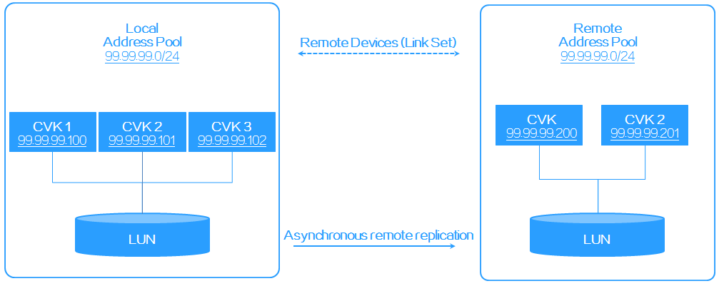
As shown in Figure 18:
· Assign the CVK hosts at the protected site to a local address pool, and assign the CVK hosts at the recovery site to a remote address pool.
· Create a remote device for the address pools and configure asynchronous replication settings.
Figure 18 Storage disaster recovery network diagram
Adding address pools
An address pool is a group of hosts configured with the same replication network in a cluster. The hosts in an address pool are called replication nodes.
Adding a local address pool
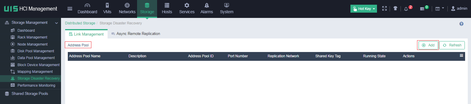
1. On the top navigation bar, click Storage, and then select Storage Disaster Recovery from the left navigation pane.
2. Click the Link Management tab.
3. Click Add in the Address Pools section.
Figure 19 Adding a local address pool
4. In the dialog box that opens, configure the address pool parameters and then click OK.
The replication network is used for synchronizing data between block devices in a protected site and recovery site.
Figure 20 Configuring local address pool parameters

5. Assign multiple replication nodes to the local address pool for redundancy, and then click OK.
Figure 21 Selecting replication nodes
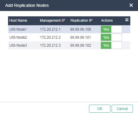
The local address pool is added successfully.
Figure 22 Local address pool

Adding a remote address pool
1. Log in to the UIS console of the recovery site.
2. On the top navigation bar, click Storage, and then select Storage Disaster Recovery from the left navigation pane.
3. Click the Link Management tab.
4. Click Add in the Address Pools section.
5. In the dialog box that opens, configure the address pool parameters and click OK.
Figure 23 Adding a remote address pool

6. Assign multiple replication nodes to the remote address pool for redundancy, and then click OK.
Figure 24 Selecting replication nodes

The remote address pool is added successfully.
Figure 25 Remote address pool

Adding a remote device
A remote device is abstracted from a set of links between a remote address pool and a local address pool. You can add a remote device on either the protected or recovery site. This example creates a remote device at the protected site.
To add a remote device:
1. On the top navigation bar, click Storage, and then select Storage Disaster Recovery from the left navigation pane.
2. Click the Link Management tab.
3. Click Add in the Remote Devices section.
Figure 26 Adding a remote device

4. In the dialog box that opens, configure the following remote device parameters and then click OK.
¡ Address Pool Name: Select an address pool in the local cluster.
¡ Remote Address Pool ID: Specify a remote address pool ID. This ID is automatically assigned during remote address pool creation. You can log in to the UIS console of the remote recovery site to check this parameter.
¡ Local IP: Select a replication network IP address in the local cluster. You can select the IP address of any replication node in the local address pool. This IP address is used only in link establishment. All replication nodes participate in data synchronization.
¡ Remote IP: Enter a replication network IP address in the remote cluster. You can enter the IP address of any replication node in the remote address pool. This IP address is used only in link establishment. All replication nodes participate in data synchronization.
¡ Remote Port Number: Specify the port number of the remote address pool. This port number is automatically assigned during remote address pool creation. You can log in to the UIS console of the remote recovery site to check this parameter.
¡ Remote Shared Key Tag: Enter the shared key tag for the remote address pool. You can log in to the UIS console of the remote recovery site to check this parameter.
¡ Remote Shared Key: Enter the shared key for the remote address pool.
Figure 27 Configuring a remote device

The remote device is created.
Figure 28 Remote device
![]()
Creating an asynchronous replication pair
Asynchronous replication copies data from a local block device to a remote block device based on a replication relationship called asynchronous replication pair. When the local block device fails, its backup data on the remote block device can be used to fast resume services.
To create an asynchronous replication pair:
1. On the top navigation bar, click Storage, and then select Storage Disaster Recovery from the left navigation pane.
2. Click the Async Remote Replication tab.
3. Click Add.
Figure 29 Adding an asynchronous replication pair

4. In the dialog box that opens, select a remote device and then click Next.
Figure 30 Selecting a remote device

5. In the Primary Block Device section, select a disk pool and a data pool. Then, select a primary block device and then click Next.
Figure 31 Selecting a primary block device

6. In the Secondary Block Device section, select a disk pool and a data pool. Then, select a secondary block device and then click Next.
Figure 32 Selecting a secondary block device

7. Configure replication settings.
¡ Initial Sync: Specify an initial synchronization policy for the asynchronous replication pair.
- Automatic—The system automatically synchronizes the primary and secondary block devices for data consistency immediately after the replication pair is created.
- Manual—Make sure you perform synchronization after the replication pair is created. The pair will stay in Split state until you perform a manual synchronization.
- Skip—Select this option only if you are sure that the primary and secondary block devices have data consistency.
As a best practice, select Automatic. If you select another option, you must manually synchronize data before a recover plan test.
¡ Speed: Specify a data replication speed.
- Low—The speed is equal to or lower than 5 Mbps.
- Medium—The speed is equal to or lower than 20 Mbps.
- High—The speed is equal to or lower than 70 Mbps.
- Ultra—The speed is not limited and depends on the network condition of the cluster.
¡ Restore Mode: Specify a restoration mode for the asynchronous replication pair.
- Auto—After a failure, the system will automatically perform synchronization periodically to recover data from the failure.
- Manual—After a failure, the system will not perform an automatic synchronization. You can manually recover data from More Actions > Sync on the Async Remote Replication tab.
¡ Sync Policy: Specify a timing policy for scheduled automatic synchronization between the primary and secondary block devices.
- Interval-Based (Timer Starts on Start of Sync)—Timer starts upon the start of this synchronization. The next synchronization automatically starts after the interval timer expires.
- Interval-Based (Timer Starts on Completion of Sync)—Timer starts upon the completion of this synchronization. The next synchronization automatically starts after the interval timer expires.
- Time-Based—Synchronization starts at the specified time.
- Not Configurable—No synchronization policies are set. You can manually perform a synchronization from More Actions > Sync on the Async Remote Replication tab.
¡ Sync interval: Set the synchronization interval. This parameter is available if you select Interval-Based (Timer Starts on Start of Sync) or Interval-Based (Timer Starts on Completion of Sync) for Sync Policy.
¡ Sync Time: Specify a point in time at which synchronization will be performed. This parameter is available if you select Time-Based for Sync Policy.
Figure 33 Configuring replication settings

8. Click Finish.
The asynchronous replication pair is created, and data synchronization is in progress.
Figure 34 Asynchronous replication pair

Configuring SRM
Adding SRAs for the local and remote sites
If the storage arrays of the protected site and recovery site support SRAs, you must configure storage array managers for the sites. After you add the sites and storage array managers, synchronize the storage replication information. You can configure SRM settings from the UIS console of one site and synchronize them to the other site.
Adding SRAs for the local site
1. On the top navigation bar, click Services.
2. From the left navigation pane, select Services > SRM > Sites.
3. Select the local site, and then click Add Storage Array Manager.
4. Select ONEStor as the storage array type, enter the Handy IP address and username and password used for logging in to the ONEStor storage cluster.
You can view the IP address of the storage cluster on the summary page for the storage cluster. On a stateful failover system, the IP address is the HA management IP.
Figure 35 Adding a storage array manager
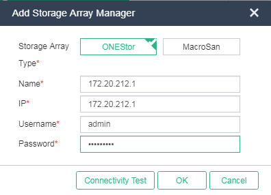
5. Click Connectivity Test to verify that the storage cluster is reachable.
6. Click OK, and then click Finish.
Adding SRAs for the remote site
1. On the top navigation bar, click Services.
2. From the left navigation pane, select Services > SRM > Sites.
3. Select the remote site, and then click Add Storage Array Manager.
4. Select ONEStor as the storage array type, enter the Handy IP address and username and password used for logging in to the ONEStor storage cluster.
Figure 36 Adding a storage array manager

5. Click Connectivity Test to verify that the storage cluster is reachable.
6. Click OK, and then click Finish.
Synchronizing storage replication pairs
1. Click Synchronize Storage Replication Info.
Figure 37 Synchronizing storage replication pairs

2. Click the ![]() icon for the storage array
manager to view storage replication pairs.
icon for the storage array
manager to view storage replication pairs.
Figure 38 Viewing storage replication pairs

Configuring a protection group
A protection group protects a set of VMs that use the same storage pool (a LUN in a storage array) based on a protection policy. It replicates the VM data stored on a LUN in the local storage array to a LUN in a remote storage array through array-based replication when failure occurs.
Resource mapping relations associate the resources used by the protected VMs in the protected site with the sources at the recovery site. When VMs are recovered at the recovery site, the resources they use are automatically replaced with the resources of the recovery site.
To configure a protection group:
1. On the top navigation bar, click Services.
2. From the left navigation pane, select Services > SRM > Protection Groups.
3. Click Add Protection Group.
4. Configure the protection group parameters, and then click Next.
¡ Name: Enter the name of the protection group. The name must be unique in UIS Manager.
¡ Protection site: Click ![]() to select a protected site to associate with the protection group.
to select a protected site to associate with the protection group.
¡ Recovery Site: Click ![]() to select a recovery site to associate with the protection group.
to select a recovery site to associate with the protection group.
¡ Original Host Pool: Click ![]() to select a host pool for the protected site.
to select a host pool for the protected site.
¡ Target Host Pool: Click ![]() to select a host pool for the recovery
site.
to select a host pool for the recovery
site.
¡ Auto VM Protection: A VM is automatically added to a protection group when the following conditions are met:
- The storage resource, vSwitch, and port profile used by the VM belong to the protection group.
- No VM with the same name exists in the protection group.
- The VM does not use any optical drives or floppy drives.
Figure 39 Configuring a protection group

5. To add a resource mapping relation, drag the ![]() ,
, ![]() , or
, or ![]() icon.
icon.
When you add a storage mapping, you must specify the storage pool type and storage type. You must select Shared File System as the storage pool type for storage arrays that do not support SRAs.
Figure 40 Selecting storage for a storage mapping
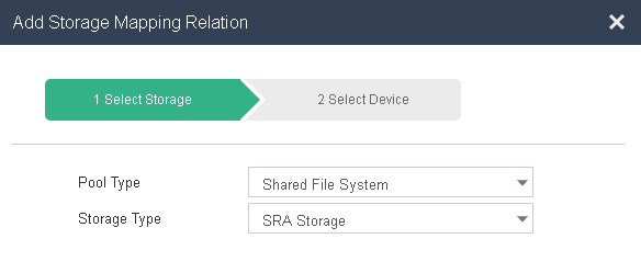
Figure 41 Selecting devices for a storage mapping

6. Click Finish.
Figure 42 Resource mappings

7. Select the protection group, and then click Add VM.
8. Select VMs and then click OK.
Before you select a VM, detach its optical drivers and floppy drivers.
Figure 43 Adding VMs to the protection group

Creating a recovery plan
A recovery plan contains a set of policies for recovering the VMs in a protection group.
To create a recovery plan:
1. On the top navigation bar, click Services.
2. From the left navigation pane, select Services > SRM > Recovery Plans.
3. Click Add Recovery Plan.
4. Enter the name and description, and then select a protection group and a cluster where protected VMs will be restored.
A protection group can be protected by only one recovery plan.
Figure 44 Adding a recovery plan

5. Click OK.
The recovery plan is in Initialize state after creation.
Figure 45 Recovery plan

Running a recovery plan
UIS Manager provides the following options to run a recovery plan:
· Testing a recovery plan.
· Running scheduled recovery.
· Running failure recovery.
· Running reverse recovery.
Restrictions and guidelines
· Make sure data synchronization has been performed for storage replication pairs before the first execution of a recovery plan.
· For non-SRA storage, disable resource protection at the recovery site before you run a recovery plan. If you do not disable resource protection, storage devices cannot boot correctly, and execution of the recovery plan fails.
· Make sure protected VMs can reach the storage devices specified in storage mappings during execution of a recovery plan, and the recovery cluster has enough resources to restore the protected VMs.
· Make sure the protected and recovery sites have connectivity during execution of a recovery plan. Make sure the hosts with mapped storage devices attached operate correctly.
Testing a recovery plan
A recovery plan test simulates the process of recovering services on a recovery site upon protected site failure to verify the correctness of a recovery plan. The test does not affect the services provided by the protected site and is manually started and stopped.
In a recovery plan test, protected VMs are attached to the LUNs of the recovery site. You must manually clear the environment after finishing a recovery plan test.
Starting testing a recovery plan
1. On the top navigation bar, click Services.
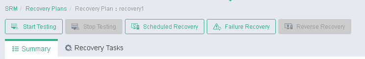
2. From the left navigation pane, select Services > SRM > Recovery Plans > recovery plan name.
3. Click Start Testing.
Figure 46 Starting testing the recovery plan
4. In the dialog box that opens, select an execution mode, and then click OK.
If your storage devices have synchronized data, you can select Skip storage synchronization.
Figure 47 Selecting an execution mode

5. Click the Recovery Tasks tab to view the state of the recovery task.
Figure 48 Recovery task state

6. Click the execution time link for the recovery task to view test details.
Figure 49 Viewing test details

7. Verify that the protected VMs have been restored on the hosts with mapped storage resources attached at the recovery site.
Figure 50 Viewing the test result at the recovery site
Finishing testing a recovery plan
You must manually finish a recovery plan test to clear disaster recovery data and restore the state of the recovery plan to Ready.
To finish testing a recovery plan:
1. On the top navigation bar, click Services.
2. From the left navigation pane, select Services > SRM > Recovery Plans > recovery plan name.
3. Click Stop Testing.
4. Click the Recovery Tasks tab to view the state of the recovery task.
Figure 51 Recovery task state

5. Click the execution time link for the recovery task to view test details.
Figure 52 Viewing test details

6. Verify that the protected VMs have been deleted from the recovery site, and the mapped storage resources have been suspended.
Figure 53 Viewing the test result at the recovery site

7. Verify that the recovery plan is in Ready state.
Figure 54 Recovery plan in Ready state

Running scheduled recovery
Scheduled recovery shuts down the protected VMs at the protected site and replicates their data to the recovery site for maintenance purposes when both sites are operating correctly. You can run a recovery plan by following the recovery steps or directly restoring VMs if all steps in the recovery plan are ready before VM restoration.
To run scheduled recovery:
1. On the top navigation bar, click Services.
2. From the left navigation pane, select Services > SRM > Recovery Plans > recovery plan name.
3. Click Scheduled Recovery.
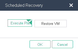
4. In the dialog box that opens, select an execution mode, and then click OK.
Figure 55 Running scheduled recovery
5. Click the Recovery Tasks tab to view the state of the recovery task.
Figure 56 Recovery task state

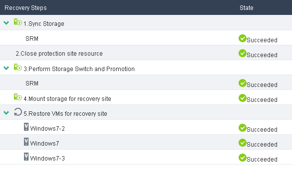
6. Click the execution time link for the recovery task to view task details.
Figure 57 Viewing task details
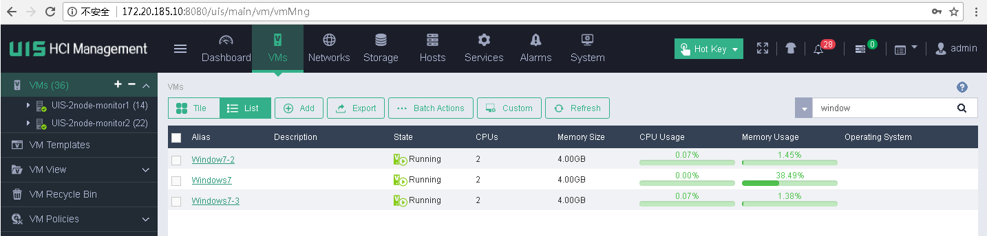
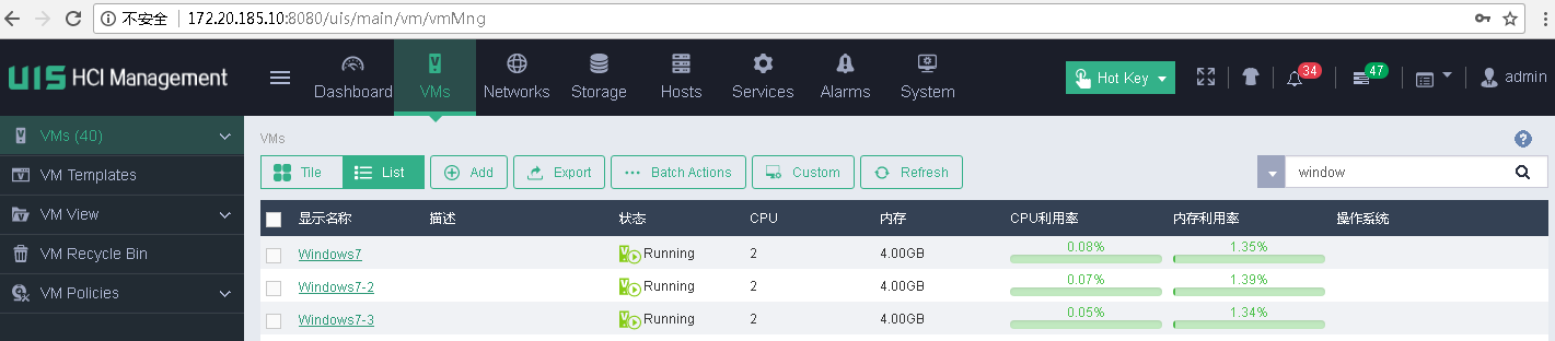
7. Verify that the protected VMs have been restored at the recovery site.
Figure 58 Viewing the task result at the recovery site

8. Verify that the protected VMs have been shut down at the protected site.
Figure 59 Viewing the task result at the protected site

Running reverse recovery
Reverse recovery restores the protected VMs at the recovery site to the protected site when the protected site recovers or after scheduled recovery is performed.
Before you run reverse recovery, make sure the protected and recovery sites operate correctly and have connectivity, and the hosts with mapped storage resources attached operate correctly.
To run reverse recovery:
1. On the top navigation bar, click Services.
2. From the left navigation pane, select Services > SRM > Recovery Plans > recovery plan name.
3. Click Reverse Recovery.
4. Click the Recovery Tasks tab and click the execution time link for the recovery task.
Figure 60 Recovery task state

Figure 61 Viewing task details

5. Verify that the protected VMs have been deleted from the recovery site, and the mapped storage resources have been suspended.
Figure 62 Viewing the task result at the recovery site

6. Verify that the protected VMs have been restored at the protected site.
Figure 63 Viewing the task result at the protected site

Running failure recovery
You can run a recovery plan by following the recovery steps or directly restoring VMs if all steps in the recovery plan are ready before VM restoration.
To run failure recovery:
1. On the top navigation bar, click Services.
2. From the left navigation pane, select Services > SRM > Recovery Plans > recovery plan name.
3. Click Failure Recovery.
4. In the dialog box that opens, select an execution mode, and then click OK.
Figure 64 Running failure recovery

5. Click the Recovery Tasks tab to view the state of the recovery task.
Figure 65 Recovery task state

6. Click the execution time link for the recovery task to view task details.
Figure 66 Viewing task details

7. Verify that the protected VMs have been restored at the recovery site.
Figure 67 Viewing the task result at the recovery site
8. Verify that the protected VMs have been shut down at the protected site.
Figure 68 Viewing the task result at the protected site

