| Title | Size | Downloads |
|---|---|---|
| H3C UIS Manager Distributed Storage Configuration Guide-5W101-book.pdf | 1.15 MB |
- Table of Contents
- Related Documents
-
H3C UIS Manager
Distributed Storage Configuration Guide
Document version: 5W101-20201222
Copyright © 2020 New H3C Technologies Co., Ltd. All rights reserved.
No part of this manual may be reproduced or transmitted in any form or by any means without prior written consent of New H3C Technologies Co., Ltd.
Except for the trademarks of New H3C Technologies Co., Ltd., any trademarks that may be mentioned in this document are the property of their respective owners.
The information in this document is subject to change without notice.
About the distributed storage system
Configuring the distributed storage system
Hardware and software requirements
Configuring the distributed storage cluster
(Optional.) Configuring a shared storage pool
About the distributed storage system
The distributed storage system virtualizes disks on multiple servers into a storage resource pool to provide storage services to upper-layer applications.
The distributed storage system provides the following benefits:
· High maintainability—The operation of traditional storage arrays requires hardware, storage switches, and dedicated components such as HBA cards. The configuration and management of the storage arrays require professional skills or even the participation of storage device vendors. The distributed storage system is directly deployed across multiple servers and virtualizes disks on the servers into a storage resource pool to provide storage services, which simplifies the management and maintenance of data centers.
· High scalability—The distributed storage system supports linear expansion in both scale and performance.
· High reliability—The distributed storage system offers replication and erasure coding redundancy policies to ensure high availability of data. It distributes the replicas or data blocks and parity blocks of the data to different storage servers to ensure that the data is still available even if some storage servers or disks fail. The system can also automatically recover the data from failures.
· High availability—The distributed storage system provides the iSCSI high availability (HA) group feature. An iSCSI HA group contains multiple storage nodes and is accessible at an HA virtual IP (VIP). It can provide continuous block storage services to clients even if some storage nodes in the group fail.
· Block storage service—The distributed storage system provides block storage services accessible through iSCSI.
· Intelligent data balancing—When the number of disks in the distributed storage system decreases or increases, the system automatically balances the data across all disks.
Concepts
Storage cluster
You can deploy the distributed storage software on multiple servers to form a storage cluster. Then, you can perform centralized management on all disks on the servers through the storage cluster.
A storage cluster contains the following nodes:
· Storage node—Provides storage resources.
· Monitor node—Monitors the storage system and maintains the metadata of the storage system.
|
|
NOTE: A server can act as both a storage node and a monitor node. |
Disk pool
A disk pool is a collection of disks from one or multiple storage nodes. You can create multiple disk pools in the storage system. The system distributes replicas or fragments of data only across disks in a disk pool.
Data pool
A data pool provides block storage resources and supports the following redundancy policies:
· Replication—Protects data by creating multiple replicas of data. The replicas are distributed to different disks on different storage nodes. Data is available as long as one disk is operating correctly with the replica integrated in the disk. The more replicas you set, the more secure the data, but the more storage capacity is required.
· Erasure coding—Protects data by breaking data into n data blocks, which are then expanded and encoded with m redundant blocks (parity blocks) and stored across multiple disks. The system can recover the original data when m blocks (including data and parity blocks) fail. The process for generating parity blocks is called encoding and the process for recovering the data is called decoding.
Erasure coding provides higher storage usage efficiency and potentially higher fault tolerance than replication. However, erasure coding is more complex, requires more computation, and potentially increases the time to recover from failure. Therefore, erasure coding is usually applied to read-only data and cold data such as VM backup files and VM templates.
Client and client group
A client is a host that uses the distributed storage services. You can add multiple clients to a client group for centralized management. A client can use the distributed storage services only when the following conditions are met:
· The client has been added to a client group.
· The client group has been mapped to block devices.
iSCSI high availability
Clients access block storage resources in the storage cluster through iSCSI. An iSCSI HA group contains multiple storage nodes and is accessible at an HA VIP. It can provide continuous block storage services to clients even if some storage nodes in the group fail.
Block device
A block device is a logical storage volume (LUN) created in the storage cluster and is accessible through iSCSI. A block device is not deployed with any file systems and can be used like an unformatted disk.
A block device can be directly mounted to a VM and the operating system of the VM will recognize the block device as a physical disk. The VM can use the storage resources of the block device after the block device is partitioned and formatted.
A block device can also be formatted as a shared file system to provide shared storage services to VMs.
Shared storage pool
A shared storage pool can be mounted to multiple hosts in a cluster. To configure features that involve live VM migration such as HA, DRS, and DPM for a cluster, you must configure a shared storage pool for the cluster. During the migration of a VM using a shared storage pool, only the compute resources of the VM are migrated, which reduces the migration time.
Restrictions and guidelines
· A minimum of two servers are required to deploy a distributed storage cluster. As a best practice, do not add more than 32 servers to the cluster.
· When the server quantity is N, the number of replicas is as follows:
¡ When 2 ≤ N ≤ 6, the number of replicas is in the range of 2 to N-1.
¡ When N > 6, the number of replicas is in the range of 2 to 5.
· When the server quantity is N, (N ≥ 3), the data block quantity and parity block quantity are as shown in Table 1.
Table 1 Server quantity, data block quantity, and parity block quantity relationship
|
Parity blocks Servers |
1 |
2 |
3 |
4 |
|
3 |
2+1 (66%) |
N/A |
N/A |
N/A |
|
4 |
2+1 (66%) |
N/A |
N/A |
|
|
5 |
3+1 (75%) |
N/A |
N/A |
N/A |
|
6 |
4+1 (80%) |
N/A |
N/A |
N/A |
|
7 |
4+1 (80%) |
4+2 (66%) |
N/A |
N/A |
|
8 |
6+1 (85%) |
4+2 (66%) |
4+3 (57%) |
N/A |
|
9 |
6+1 (85%) |
6+2 (75%) |
4+3 (57%) |
N/A |
|
10 |
8+1 (88%) |
6+2 (75%) |
6+3 (66%) |
N/A |
|
11 |
8+1 (88%) |
8+2 (80%) |
6+3 (66%) |
6+4 (60%) |
|
12 |
8+1 (88%) |
8+2 (80%) |
8+3 (72%) |
6+4 (60%) |
|
13 |
8+1 (88%) |
8+2 (80%) |
8+3 (72%) |
8+4 (66%) |
|
14 |
12+1 (92%) |
8+2 (80%) |
8+3 (72%) |
8+4 (66%) |
|
15 |
12+1 (92%) |
12+2 (85%) |
8+3 (72%) |
8+4 (66%) |
|
16 |
12+1 (92%) |
12+2 (85%) |
12+3 (80%) |
8+4 (66%) |
|
17 |
12+1 (92%) |
12+2 (85%) |
12+3 (80%) |
12+4 (75%) |
|
18 |
16+1 (94%) |
12+2 (85%) |
12+3 (80%) |
12+4 (75%) |
|
19 |
16+1 (94%) |
16+2 (88%) |
12+3 (80%) |
12+4 (75%) |
|
20 |
16+1 (94%) |
16+2 (88%) |
16+3 (84%) |
12+4 (75%) |
|
21 to 32 |
16+1 (94%) |
16+2 (88%) |
16+3 (84%) |
16+4 (80%) |
· The distributed storage system will rebalance the data across data disks when the number of data disks in the system changes, for example, when a host or disk is added or fails. Do not delete disks in use or hosts from the system when data is unbalanced.
Configuring the distributed storage system
Prerequisites
The configuration was created and verified in a lab environment, and all the servers and software were started with the factory default configuration. If you have configured the devices under test, make sure the existing configuration does not conflict with the configuration in the following examples.
Hardware and software requirements
Hardware requirements
This document is not restricted to a specific server model. The configuration in this document might differ from the configuration in actual deployment.
The hardware used in this document is shown in Table 2. The hardware requirements are not intended to be mandatory or recommended during the actual deployment.
|
Hardware |
Requirements |
|
Server model |
H3C UIS-Cell 3010 G3 |
|
Server quantity |
4 |
|
CPU |
2 × 12-core Intel Xeon Silver 4116 @ 2.10GHz CPUs |
|
Memory |
128 GB |
|
Local data disk |
4 × 300G 12G SAS 15K 2.5-inch EP HDD Generic Modules |
|
NIC |
2-port 10-GE fiber port mLOM Ethernet adapter (SFP+)-560 L2 2-port 10-GE fiber port Ethernet adapter (SFP+)-520F-B2 |
Software requirements
|
Software |
Version |
|
H3C UIS Manager |
E0712 |
Procedure
Configuring the distributed storage cluster
Adding a disk pool
Restrictions and guidelines
A disk must contain data disks from a minimum of two hosts.
Procedure
1. Log in to UIS, and then click Storage on the top navigation bar.
2. From the navigation pane, select Storage Management > Disk Pool Management.
Figure 1 Disk pools

3. Click Add, and then perform the following tasks:
a. Enter a name for the disk pool.
b. Select a provisioning mode, which determines how a disk pool allocates storage space to a block device and whether space overcommitment is allowed. Options include the following:
- Thick—Allocates the maximum allowed amount of storage space to a block device when the block device is created. The capacity specified for a thick-provisioned block device cannot exceed the available capacity of the disk pool.
- Thin—Allocates storage space to a block device in a flexible on-demand manner. The capacity specified for a thin-provisioned block device can exceed the available capacity of the disk pool.
c. Select a deployment mode. Options include the following:
- SSDs Caches + HDDs—Deploy HDDs as data disks to store data and deploy SSDs as read and write cache disks to accelerate reads and writes.
- All SSDs—Deploy SSDs as data disks to store data without using data caches. Use this mode to provide high-performance storage services.
- All HDDs—Deploy HDDs as data disks to store data without using data caches. Use this mode to provide normal storage services.
d. Specify a cache size.
The cache size is configurable only when the SSDs Caches + HDDs deployment mode is used. The system will partition SSDs based on the number of data disks. Each data disk corresponds to a cache partition. The default cache size is 50 GB. You can increase the cache size when there is a large amount of service data to process.
e. Click OK.
Figure 2 Configuring disk pool parameters

4. Click the ![]() icon
for the added disk pool, select the disks to be added to the disk pool, and
then click Next.
icon
for the added disk pool, select the disks to be added to the disk pool, and
then click Next.
Figure 3 Adding disks to the disk pool

5. Verify that the disk information is correct, and then click Finish.
Figure 4 Verifying disk information

Adding a data pool
1. Click Storage on the top navigation bar.
2. From the navigation pane, select Storage Management > Data Pool Management.
Figure 5 Data pools

3. Click Add, and then perform the following tasks:
a. Enter a name for the data pool.
b. Select a disk pool.
c. Select a redundancy policy. Options include Replication and Erasure Coding.
- Replication—Protects data by creating multiple replicas of data. The more replicas you set, the more secure the data. When you select the replication redundancy policy, select the number of replicas. If the number of replicas is N, the available capacity is the total capacity divided by N. As a best practice, use three or more replicas in scenarios that require high data reliability.
- Erasure Coding—Protects data by breaking data into blocks, which are expanded and encoded with redundant data pieces and stored across multiple physical entities such as disks or storage nodes. When you select the erasure coding redundancy policy, configure the following parameters:
# Data Blocks—Specifies the number of blocks into which data is divided. A data block is saved on a disk of a storage node. Data durability increases with the number of data blocks.
# Parity Blocks—Specifies the number of parity blocks used in conjunction with data blocks to recode data. A parity block is saved on a disk of a storage node, and parity blocks and data blocks must be saved on different storage nodes. Data durability increases with the number of parity blocks at the expense of storage capacity.
# Strip Size—Specifies the data block size used in data encoding and decoding. A small strip size is suitable for random read/write. A large strip size is suitable for sequential read/write. As a best practice, use a large strip size in common VM scenarios and a small strip size in database scenarios.
d. Click OK.
Figure 6 Configuring data pool parameters

Adding a client
Restrictions and guidelines
· For a host not in the UIS cluster to access the distributed storage resources, perform this task on the host.
· This task is not required for hosts in the UIS cluster, which have been automatically configured as clients during system initialization.
Procedure
1. Click Storage on the top navigation bar.
2. From the navigation pane, select Storage Management > Mapping Management.
3. Click the Clients tab.
Figure 7 Clients
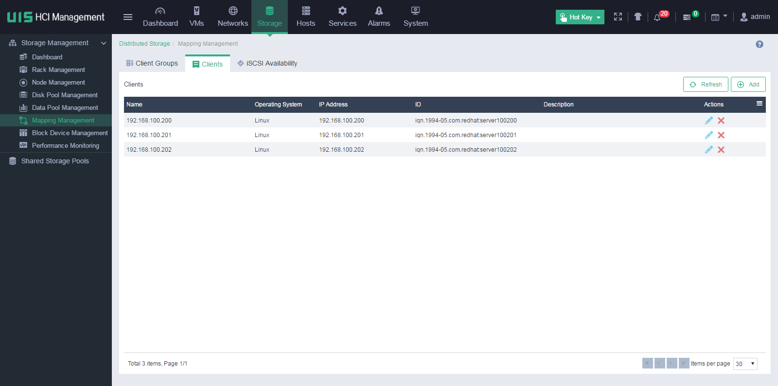
4. Click Add.
5. Enter a name and a description for the client and select an operating system.
6. Enter the IP address that connects the client to the storage front-end network of the storage cluster.
7. Enter the iSCSI qualified name (IQN) of the client.
An IQN uniquely identifies an iSCSI initiator or target and enables a client to connect to block devices.
8. Click OK.
Figure 8 Configuring client parameters

Adding a client group
Restrictions and guidelines
· After you configure a host not in the UIS cluster as a client, you must manually add the client to a client group for the client to access the distributed storage resources.
· The system has automatically created a client group named uistorHostGroup and added all hosts in UIS cluster to the group during system initialization. To add a host in the UIS cluster to another client group, you must first remove the host from client group uistorHostGroup.
· Client group uistorHostGroup cannot be deleted.
Procedure
1. Click Storage on the top navigation bar.
2. From the navigation pane, select Storage Management > Mapping Management.
3. Click the Client Groups tab.
Figure 9 Client groups

4. Click Add.
5. Enter a name and a description for the client group, and then click OK.
Figure 10 Configuring client group parameters

6. Select the created client group, and then click Add on the Clients tab on the Client Groups page.
Figure 11 Adding clients to the client group

7. Select one or multiple clients, and then click OK.
You can also click Add to add hosts not in the cluster to the client group.
Figure 12 Selecting clients

The added clients will be displayed in the client list on the Client Groups page.
Adding an iSCSI HA group
1. Click Storage on the top navigation bar.
2. From the navigation pane, select Storage Management > Mapping Management.
3. Click the iSCSI Availability tab.
Figure 13 iSCSI HA groups

4. Click Add, and then configure the following parameters:
¡ HA VIP—Enter an IP address in the storage front-end network as the HA VIP for clients to access block storage resources in the storage cluster.
¡ HA Group ID—Specify an ID for the iSCSI HA group. The ID will be deployed to all primary and backup nodes in the group. Storage services can be switched only between nodes with the same HA group ID.
¡ Primary Node IP—Specify the storage front-end network IP address of a storage node. This node will work as the primary node in the HA group to provide block storage network access.
¡ Backup Node IP—Specify the storage front-end network IP address of a storage node. This node will work as a backup node in the HA group and take over to provide block storage network access when the primary node fails.
Figure 14 Configuring iSCSI HA group parameters

5. Click OK.
The created iSCSI HA group will be displayed in the iSCSI HA group list.
Creating a block device
Restrictions and guidelines
· A block device can be directly mounted to hosts in the UIS cluster as a shared file system. For more information, see "Mounting a block device to hosts as a shared file system" or "(Optional.) Configuring a shared storage pool."
· For a host not in the UIS cluster to detect and use a block device, you must configure the host as a client and add the client to a client group that is mapped to the block device.
Procedure
1. Click Storage on the top navigation bar.
2. From the navigation pane, select Storage Management > Block Device Management.
Figure 15 Block devices

3. Click Add.
4. Enter a name and a description for the block device, and select a data pool.
5. Select the client group to which the block device will be mapped.
Only clients in the selected client group can detect the block device and uses its storage resources.
6. Specify the capacity.
¡ If the disk pool to which the selected data pool belongs uses thin provisioning mode, storage space is allocated to the block device in a flexible on-demand manner. In this scenario, the capacity specified for the block device can exceed the available capacity of the data pool.
¡ If the disk pool to which the selected data pool belongs uses thick provisioning mode, the specified amount of storage space will be allocated to the block device. In this scenario, the capacity specified for the block device cannot exceed the available capacity of the data pool.
Figure 16 Configuring block device parameters

7. Click OK.
Mounting a block device to hosts as a shared file system
1. Click Storage on the top navigation bar.
2. From the navigation pane, select Storage Management > Block Device Management.
Figure 17 Block devices

3. Click the ![]() icon for the created block
device.
icon for the created block
device.
4. To enable automatic VM deployment, select On for the Service Storage parameter.
5. Click Search Available Hosts.
6. Select one or multiple hosts to use the shared file system, and then click OK.
Figure 18 Mounting the block device to hosts as a shared file system

7. In the dialog box that opens, click OK.
Figure 19 Confirming operation

8. In the dialog box that opens, click OK to format the shared file system.
Figure 20 Formatting the shared file system

Creating a VM
Restrictions and guidelines
If you do not select a host when you create a VM, the system creates the VM on the host with the lightest load. The load measurement criteria include VM quantity, memory usage, and CPU usage.
Procedure
1. Click VMs on the top navigation bar.
Figure 21 VM management page

2. Click Add, configure basic VM settings, and then click Next.
Figure 22 Configuring basic settings

3. Click Disk, and then select New File for the Type parameter.
Figure 23 Configuring advanced settings

4. Click the search icon for the Storage Pool parameter, select a shared storage pool, and then click OK.
Figure 24 Selecting a storage pool

5. Configure other VM parameters as needed, and then click Finish.
(Optional.) Configuring a shared storage pool
1. Click Storage on the top navigation bar.
2. From the navigation pane, select Shared Storage Pools.
Figure 25 Shared storage pools

3. Click Add, enter a name, alias, and description, select a storage type, and then click Next.
Select iSCSI shared file system as the storage type if internal distributed storage or external IP SAN storage is used. Select FC shared file system as the storage type if FC SAN storage is used. The target path indicates the mount point of the shared file system on the host.
Figure 26 Configuring basic settings

4. Configure the following parameters:
¡ IP Address—In converged deployment mode, enter 127.0.0.1 or the iSCSI HA VIP. In distributed deployment mode, enter the iSCSI HA VIP. If external IP SAN storage is used, enter the IP address of the IP SAN storage server. If there are multiple paths to the IP SAN storage, enter multiple IP addresses separated by semicolons (;). This parameter is required for an iSCSI shared file system.
¡ LUN—Select the block device created in "Creating a block device" as the LUN for the shared file system. This parameter is required for an iSCSI shared file system.
¡ NAA—Select an NAA. The NAA of an iSCSI shared file system is determined by the selected LUN. This parameter is required for an FC shared file system.
¡ Service Storage—Select whether to enable service storage. As a best practice, enable service storage to enable automatically deployed VMs to use the shared file system.
Figure 27 Configuring LUN settings

5. Click Next.
6. Select one or multiple hosts to use the shared storage pool, and then click Finish.
Figure 28 Selecting hosts

7. In the dialog box that opens, click OK.
Figure 29 Confirming operation

8. In the dialog box that opens, click OK to format the shared file system.
Figure 30 Formatting the shared file system

Scaling the storage cluster
To scale the storage cluster, you can add hosts or disks to the cluster. The system will rebalance the data across data disks when new hosts or disks are added.
Restrictions and guidelines
· Before scaling the storage cluster, make sure the remaining CPUs that the UIS, CAS, and distributed storage licenses can manage are not fewer than the CPUs on the hosts to be added to the cluster. If the licenses do not meet the requirements, apply for new licenses first.
· When you scale the storage cluster by adding hosts, make sure the hosts to be added to the cluster meet the following requirements:
¡ The UIS version of the hosts must be consistent with the version of UIS manager.
¡ The network planning of the hosts must be consistent with the network planning made during initial UIS deployment. Network planning settings include the management, service, and storage networks, NIC quantity, and network reuse settings.
Adding hosts
Restrictions and guidelines
If the NIC reuse settings of a host to add are different from those of an existing host, the NIC settings of the existing host become invalid. You must reconfigure NIC settings for the existing host. NIC reuse allows a network to share a NIC with other networks. For example, assume that the management network and service network of host A use NICs eth0 and eth1, respectively, and the storage front-end network and storage back-end network of host A share NICs eth2 and eth3. If you configure the management network and service network of host B to share NIC eth0 and configure the storage front-end network and storage back-end network of host B to share NICs eth1 and eth2, the NIC settings of host A will become invalid.
Procedure
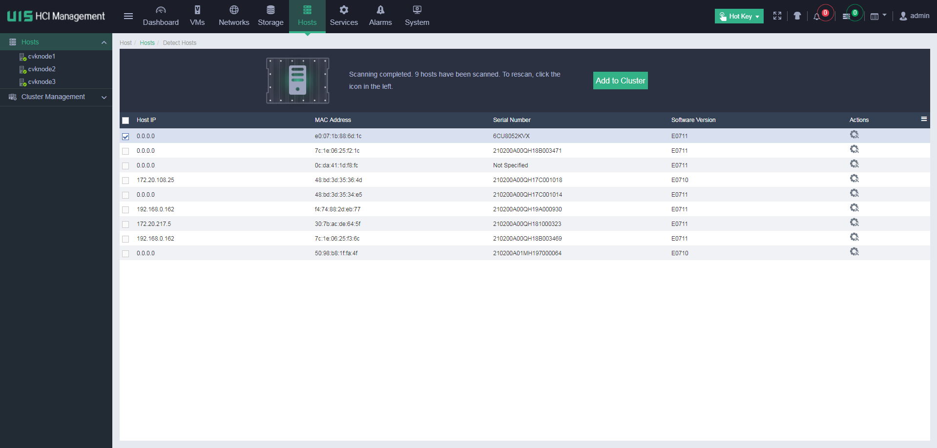
1. Click Hosts on the top navigation bar.
2. Click Detect Hosts.
Figure 31 Detecting hosts

3. Click the ![]() icon to scan hosts.
icon to scan hosts.
Figure 32 Scanning hosts
4. Click the ![]() icon
in Actions column of the target host.
icon
in Actions column of the target host.
The custom configuration window opens.
Figure 33 Custom configuration window

5. Configure the following parameters:
¡ NIC Template—Select whether to enable the NIC template feature. After you enable this feature, the network settings of the current host will be used as the configuration template for other hosts. The system automatically deploys the network settings to all hosts to be added to the cluster. To enable this feature, make sure the hosts to be added to the cluster have active physical interfaces with the same names as the physical interfaces on the current host and the physical interfaces meet the minimum rate requirements. For example, if you enable the NIC template feature for host A that uses eth0 as the management network interface, eth1 as the service network interface, and eth2 and eth3 as the storage network interfaces, all the hosts to be added to the cluster must meet the following requirements:
- Have interfaces eth0, eth1, eth2, and eth3 and the interfaces are active.
- The rates of interfaces eth0 and eth1 are equivalent to or higher than 1000 Mbps.
- The rates of interfaces eth2 and eth3 are equivalent to or higher than 10000 Mbps.
If a host does not meet the requirements, you must manually configure network settings for the host.
¡ IP Address—Specify IP addresses for the networks. If you do not specify IP addresses for the hosts, the system automatically assigns IP addresses to the hosts, which start from the first IP address in each network and are incremented by one. The first IP address in the management network is assigned to the management node. The service network IP address is not required.
¡ Physical Interfaces—Click the ![]() icon in the Physical Interfaces column for a network to specify physical NICs for the network.
icon in the Physical Interfaces column for a network to specify physical NICs for the network.
The management network, storage front-end network, and storage back-end network interfaces are required, and the service network interfaces are optional. If you do not specify service network interfaces for a host, the system will not automatically create a service network virtual switch for the host after the initialization. You must manually create a service network virtual switch for the host.
Figure 34 Selecting NICs

¡ LAGG Mode—Select a link aggregation mode for the physical NICs. Options include Static and Dynamic. If dynamic link aggregation mode is used, you must enable LACP on the physical switch. This mode is configurable only when multiple physical NICs are selected.
¡ LB Mode—Select a load balancing mode for the physical NICs. This parameter is configurable only when multiple physical NICs are selected. Options include the following:
- Advanced—Load balances packets based on the Ethernet type, IP protocol, source IP address, destination IP address, source port number, and destination port number. As a best practice, use the advanced load balancing mode.
- Basic—Load balances packets based on the source MAC address and VLAN tag.
- Active/Standby—Load balances packets based on the primary and backup roles of physical NICs. If the primary NIC fails, traffic is automatically switched to the backup NIC. This mode is available only when the static link aggregation mode is used.
6. Click OK.
7. Click Add to Cluster.
8. Verify that the host settings are correct, and then click OK.
Figure 35 Verifying host settings

The host configuration window opens.
Figure 36 Host configuration window

After the host is configured successfully, the disk selection window opens automatically.
9. Add the disks on the host to a disk pool, and then click Next.
Figure 37 Adding disks to a disk pool

10. Click the ![]() icon
to edit the host role and verify that the data disk and cache disk information
is correct.
icon
to edit the host role and verify that the data disk and cache disk information
is correct.
Figure 38 Editing host role and verifying disk information

11. Click the Disk Pools tab and verify that the data disk and cache disk information is correct.
Figure 39 Verifying disk pool information

12. Click Finish.
Adding disks
After you add new disks to a storage node, the system can automatically detect these disks. To scale the storage cluster by using these disks, perform this task to add the disks to the cluster.
Restrictions and guidelines
· For a disk pool using All SSDs deployment mode, you can add only SSDs to the disk pool as data disks.
· For a disk pool using All HDDs or SSDs Caches + HDDs deployment mode, you can add only HDDs to the disk pool as data disks.
Procedure
1. Click Storage on the top navigation bar.
2. From the navigation pane, select Storage Management > Node Management.
3. On the Storage Nodes tab, select a storage
node, and then click the ![]() icon in the Actions column
of an unused or unconfigured disk.
icon in the Actions column
of an unused or unconfigured disk.
Figure 40 Storage node management page

4. Select a disk pool for the disk, and then click OK.
Figure 41 Selecting a disk pool

5. Click OK.
Figure 42 Confirming operation

