- Released At: 12-12-2022
- Page Views:
- Downloads:
- Table of Contents
- Related Documents
-
|
|
|
H3C CR16000-F Router Series |
|
POS Subcard Datasheet |
|
|
|
|
Copyright © 2016 to 2022 New H3C Technologies Co., Ltd. All rights reserved.
No part of this manual may be reproduced or transmitted in any form or by any means without prior written consent of New H3C Technologies Co., Ltd.
Except for the trademarks of New H3C Technologies Co., Ltd., any trademarks that may be mentioned in this document are the property of their respective owners.
The information in this document is subject to change without notice.
Contents
Overview
The following POS subcards are available for the CR16000-F routers.
Table 1 POS subcards available for the CR16000-F routers
|
Card model |
Description |
|
PIC-PUP1L |
1-port OC-192c/STM-64c POS optical interface card (XFP, LC) |
|
PIC-TCP8L |
8-port OC-3c/OC-12c POS/GE optical interface card (SFP, LC) |
|
PIC-PSP4L |
4-port OC-48c/STM-16c POS optical interface card (SFP, LC) |
|
PIC-PS2G4L |
2-port OC-48c/STM-16c POS optical interface (SFP, LC) + 4-port 1000BASE-X optical interface card (SFP, LC) |
|
MIC-SP4L |
4-port OC-3c/STM-1c POS/ATM or 1-port OC-12c/STM-4c POS/ATM optical interface card (SFP, LC) |
|
MIC-SP8L |
8-port OC-3c/STM-1c POS optical interface card (SFP, LC) |
|
MIC-TCP8L |
8-port OC-3c/OC-12c POS/GE optical interface card (SFP, LC) |
|
MIC-PSP4L |
4-port OC-48c/STM-16c POS optical interface card (SFP, LC) |
Key features
PPP/HDLC encapsulation
The POS interfaces support two types of link encapsulation: PPP and HDLC, and support the configuration of scrambling, CRC-32 or CRC-16, frame format, and path trace bytes. With PPP encapsulation, the POS interfaces support the PAP and CHAP authentication modes.
Super subcard
As a super subcard, the PIC-TCP8L and MIC-TCP8L subcards support flexible configuration of POS and GE interfaces.
Full-range interfaces
CR16000-F routers provide full-range POS interfaces to support OC-3/STM-1, OC-12/STM-4, OC-48/STM-16, and OC-192/STM-64 to meet various networking requirements.
For information about the features of the GE interfaces on a POS subcard, see H3C CR16000-F Routers Ethernet Subcard Datasheet.
Specifications
The figures in this section are for illustration only.
PIC-PUP1L
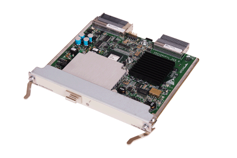
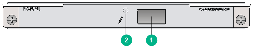
Front panel
Figure 2 PIC-PUP1L front panel
|
(1) OC192c/STM64c-XFP POS fiber port (1 in total) |
(2) POS port status LED (ACT/ALM) |
Technical specifications
|
Item |
Specifications |
|
Dimensions (H × W × D) |
18 × 165 × 142 mm (0.71 × 6.50 × 5.59 in) |
|
Power consumption |
14.3 W to 19 W |
|
Ports |
1 |
|
Connector type |
XFP/LC |
|
Port speed |
OC-192/STM-64 |
PIC-TCP8L

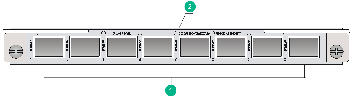
Front panel
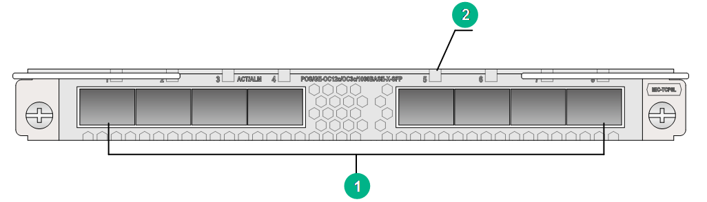
Figure 4 PIC-TCP8L front panel
|
(1) OC3c/OC12c/1000BASE-X-SFP POS/GE fiber ports (8 in total) |
|
(2) POS/GE port status LED (ACT/ALM) |
Technical specifications
|
Item |
Specifications |
|
Dimensions (H × W × D) |
18 × 165 × 142 mm (0.71 × 6.50 × 5.59 in) |
|
Power consumption |
9.7 W to 17 W |
|
Ports |
8 NOTE: You can configure a fiber port as an OC-3c/STM-1c POS fiber port, OC-12c/STM-4c POS fiber port, or 1000BASE-X GE fiber port at the CLI. By default, the fiber port operates as a 1000BASE-X GE fiber port. |
|
Connector type |
SFP/LC |
|
Port speed |
OC-3c/STM-1c, OC-12c/STM-4c, 1000 Mbps |
PIC-PSP4L
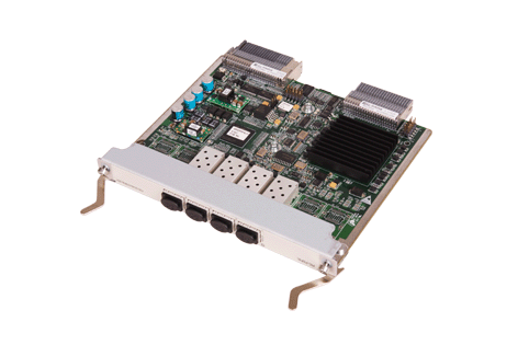
Front panel
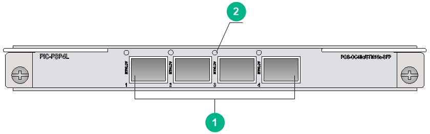
Figure 6 PIC-PSP4L front panel
|
(1) OC48c/STM16c-SFP POS fiber ports (4 in total) |
(2) POS port status LED (ACT/ALM) |
Technical specifications
|
Item |
Specifications |
|
Dimensions (H × W × D) |
18 × 165 × 142 mm (0.71 × 6.50 × 5.59 in) |
|
Power consumption |
9.7 W to 18 W |
|
Ports |
4 |
|
Connector type |
SFP/LC |
|
Port speed |
OC-48c/STM-16c |
PIC-PS2G4L
Front panel
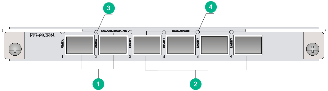
Figure 8 PIC-PS2G4L front panel
|
(1) OC48c/STM16c-SFP POS fiber ports (2 in total) |
(2) 1000BASE-X-SFP GE fiber ports (4 in total) |
|
(3) POS port status LED (ACT/ALM) |
(4) GE port status LED (LINK/ACT) |
Technical specifications
|
Item |
Specifications |
|
Dimensions (H × W × D) |
18 × 165 × 142 mm (0.71 × 6.50 × 5.59 in) |
|
Power consumption |
9.3 W to 16 W |
|
Ports |
6 |
|
Connector type |
SFP/LC |
|
Port speed |
OC-48/STM-16, 1000 Mbps |
MIC-SP4L
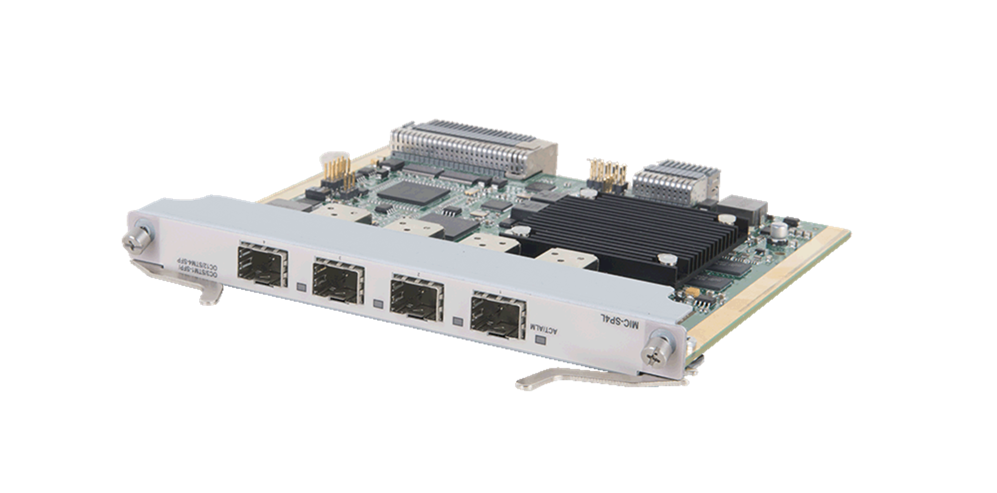
Figure 9 MIC-SP4L
Front panel
Figure 10 MIC-SP4L front panel
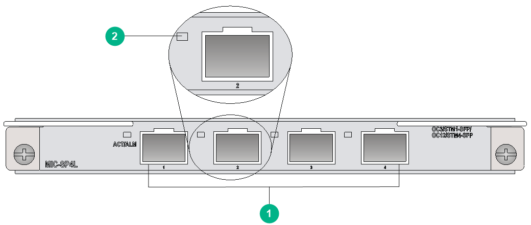
|
(1) OC-3c/STM-1c POS/ATM or OC-12c/STM-4c POS/ATM ports (4 in total) |
|
(2) POS/ATM port status LED (ACT/ALM) |
Technical specifications
|
Item |
Specifications |
|
Dimensions (H × W × D) |
18 × 165 × 142 mm (0.71 × 6.50 × 5.59 in) |
|
Power consumption |
9.6 W to 13.5 W |
|
Ports |
4 NOTE: You can configure a fiber port as an OC-3c/STM-1c POS/ATM or OC-12c/STM-4c POS/ATM fiber port at the CLI. By default, the port operates as an OC-3c/STM-1c POS fiber port.
Only port 1 can be configure as an OC-12c/STM-4c POS/ATM fiber port. |
|
Connector type |
SFP/LC |
|
Port speed |
OC-3/STM-1, OC-12/STM-4 |
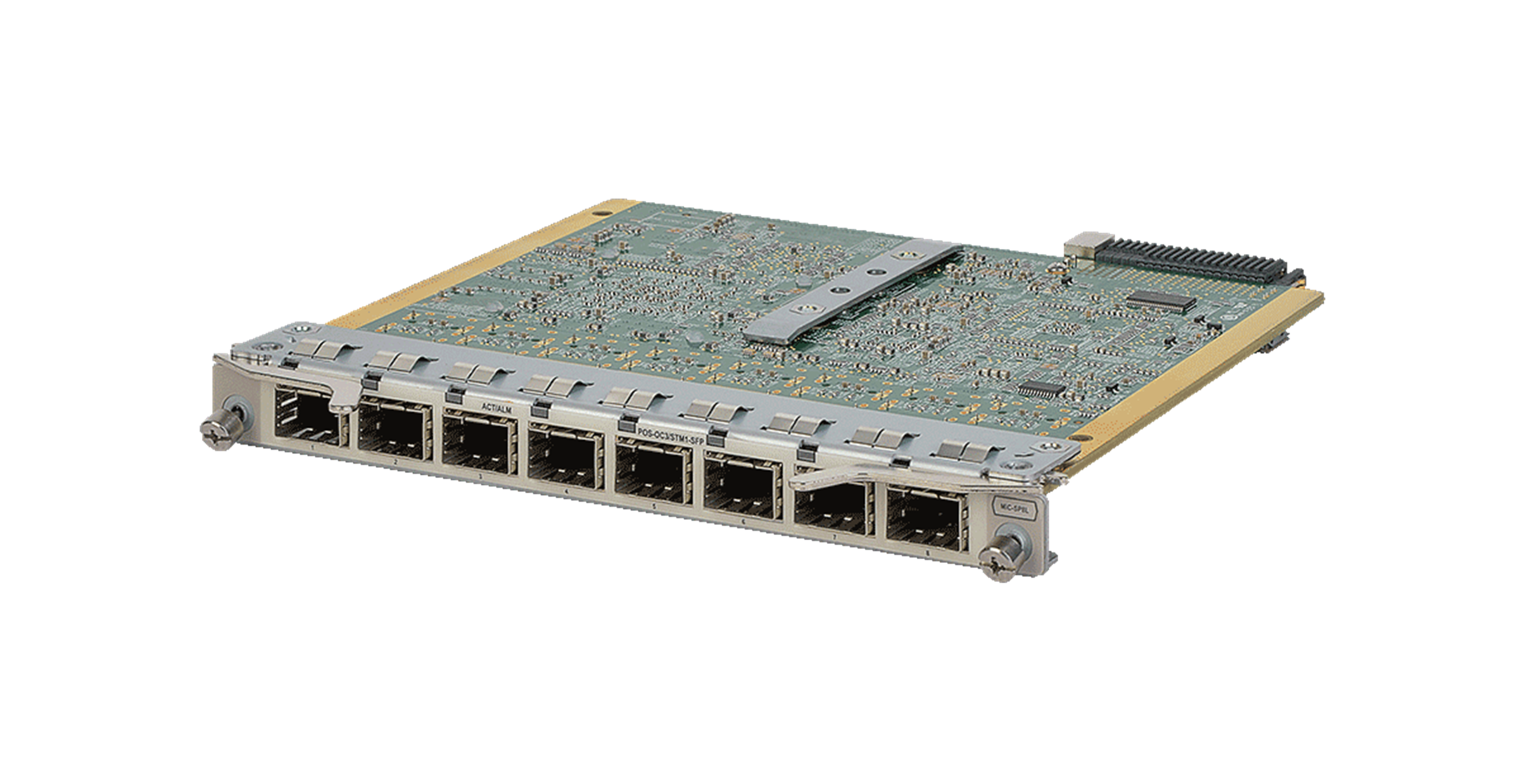
MIC-SP8L
Figure 11 MIC-SP8L
Front panel
Figure 12 MIC-SP8L front panel
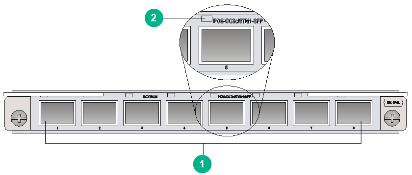
|
(1) OC-3c/STM-1c POS fiber ports (8 in total) |
(2) POS port status LED (ACT/ALM) |
Technical specifications
|
Item |
Specifications |
|
Dimensions (H × W × D) |
18 × 165 × 142 mm (0.71 × 6.50 × 5.59 in) |
|
Power consumption |
14 W to 16.3 W |
|
Ports |
8 |
|
Connector type |
SFP/LC |
|
Port speed |
OC-3/STM-1 |
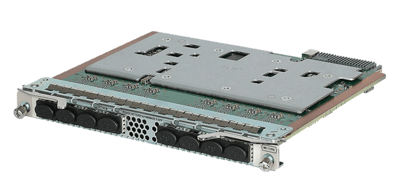
MIC-TCP8L
Figure 13 MIC-TCP8L
Front panel
Figure 14 MIC-TCP8L front panel
|
(1) OC-3c/OC-12c POS/GE fiber ports (8 in total) |
(2) POS/GE port status LED (ACT/ALM) |
Technical specifications
|
Item |
Specifications |
|
Dimensions (H × W × D) |
18 × 171 × 157 mm (0.71 × 6.73 × 6.18 in) |
|
Power consumption |
28 W to 30 W |
|
Ports |
8 |
|
Connector type |
SFP/LC |
|
Port speed |
· OC-3c/STM-1c · OC-12c/STM-4c · 1000 Mbps |
MIC-PSP4L
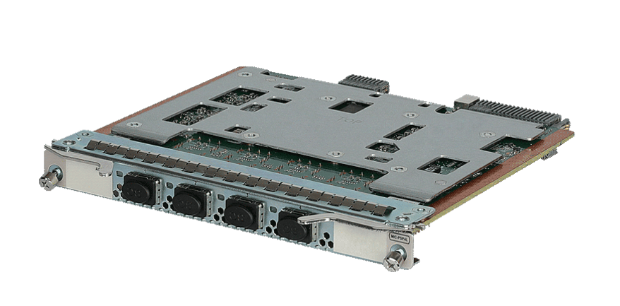
Figure 15 MIC-PSP4L
Front panel
Figure 16 MIC-PSP4L front panel
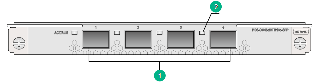
|
(1) OC-48c/STM-16c POS fiber ports (4 in total) |
(2) POS port status LED (ACT/ALM) |
Technical specifications
|
Item |
Specifications |
|
Dimensions (H × W × D) |
18 × 171 × 157 mm (0.71 × 6.73 × 6.18 in) |
|
Power consumption |
29 W to 33 W |
|
Ports |
4 |
|
Connector type |
SFP/LC |
|
Port speed |
OC-48c/STM-16c |
LEDs
Table 2 Description for the POS port status LED on a PIC subcard
|
LED mark |
Status |
Description |
|
ACT/ALM |
Steady green |
The port is up and a link is present. |
|
Steady red |
An alarm has occurred. |
|
|
Off |
The port is down. |
Table 3 Description for the POS port status LED on a MIC subcard
|
LED mark |
Status |
Description |
|
ACT/ALM |
Flashing green |
The port is up and is sending or receiving data. |
|
Steady green |
The port is up and a link is present. |
|
|
Steady red |
An alarm has occurred. |
|
|
Off |
The port is down. |
Table 4 GE port status LED description
|
LED mark |
Status |
Description |
|
LINK/ACT |
Steady green |
A link is present. |
|
Flashing green |
The port is sending or receiving data. |
|
|
Off |
No link is present. |
Table 5 POS/GE port status LED description
|
LED mark |
Status |
Description |
|
|
ACT/ALM |
In GE port mode |
Steady green |
A link is present. |
|
Flashing green |
The port is sending or receiving data. |
||
|
Off |
No link is present. |
||
|
In POS port mode |
Steady green |
The port is up and a link is present. |
|
|
Steady red |
An alarm has occurred. |
||
|
Off |
The port is down. |
||
Environment requirements
Make sure the ambient environment meets the following requirements:
· Temperature and humidity requirements
Table 6 Temperature and humidity requirements
|
Item |
Specifications |
|
Operating temperature |
0°C to 45°C (32°F to 113°F) |
|
Storage temperature |
–40°C to +70°C (–40°F to +158°F) |
|
Operating humidity |
10% RH to 95% RH, non-condensing |
|
Storage humidity |
5% RH to 95% RH, non-condensing |
· Dust protection requirements
Table 7 Dust concentration limits in the equipment room
|
Substance |
Particle diameter |
Concentration limit |
|
Dust particles |
≥ 0.5 µm |
≤ 1.8 × 10⁷ particles/m3 |
· Corrosive gas protection requirements
Table 8 Corrosive gas concentration limits in the equipment room
|
Gas |
Average concentration (mg/m3) |
Maximum concentration (mg/m3) |
|
SO2 |
0.3 |
1.0 |
|
H2S |
0.1 |
0.5 |
|
Cl2 |
0.1 |
0.3 |
|
HCI |
0.1 |
0.5 |
|
HF |
0.01 |
0.03 |
|
NH3 |
1.0 |
3.0 |
|
O3 |
0.05 |
0.1 |
|
NOX |
0.5 |
1.0 |
