- Released At: 19-12-2020
- Page Views:
- Downloads:
- Table of Contents
- Related Documents
-
|
|
|
WLAN Star-Topology IRF |
|
Technology White Paper |
|
|
|
|
Copyright © 2020 New H3C Technologies Co., Ltd. All rights reserved.
No part of this manual may be reproduced or transmitted in any form or by any means without prior written consent of New H3C Technologies Co., Ltd.
Except for the trademarks of New H3C Technologies Co., Ltd., any trademarks that may be mentioned in this document are the property of their respective owners.
The information in this document is subject to change without notice.
Implementation of star-topology IRF in WLAN
High availability technologies
Uplink and downlink redundancy
IRF data and control channel separation
IRF fabric of Layer 2 network connected AC devices
IRF fabric of directly connected two ACs
AC module IRF fabric hosted in chassis
Replacing traditional dual-AC link backup with star-topology IRF
Overview
Technical background
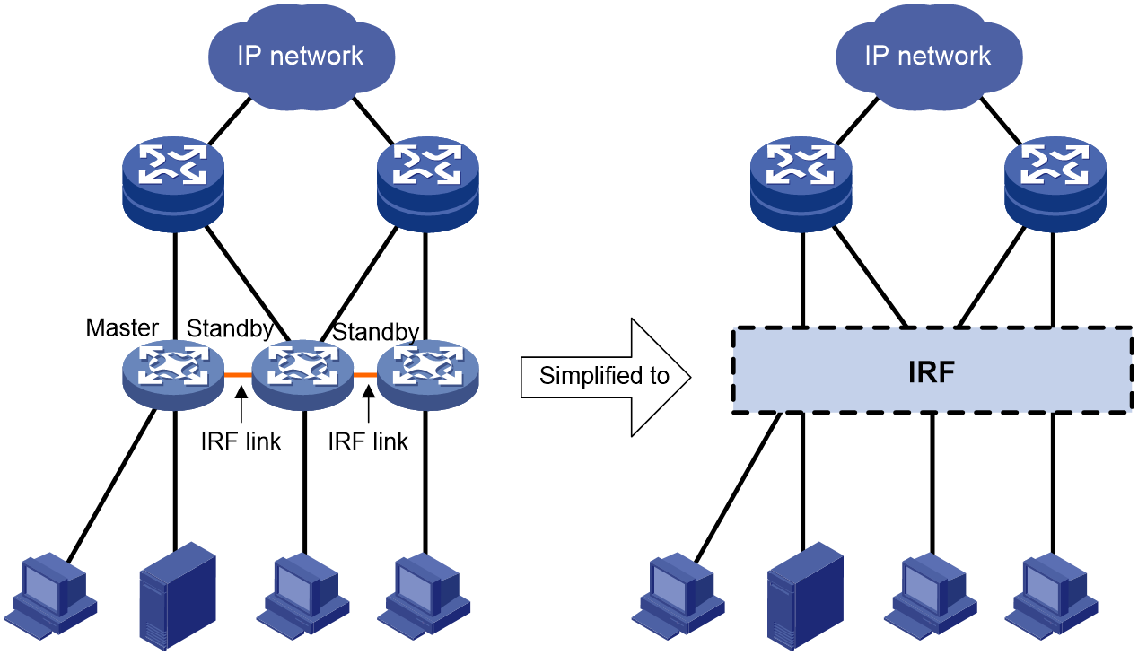
Network scalability and redundancy are important for an enterprise to accommodate growing business and guarantee business continuity. As a network scales out with additional nodes, the topological complexity grows, making the network more difficult to plan, deploy, or manage.
H3C Intelligent Resilient Framework (IRF) technology addresses these issues by virtualizing multiple physical switches into one virtual system to provide increased processing capability, unified management, and uninterrupted maintenance without complicating topology.
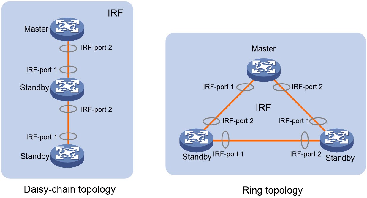
IRF was initially available in daisy-chain and ring topologies, as shown in Figure 2. Since its introduction, IRF has gained a wide support on switches to help customers build highly available, manageable, and scalable wired networks. Despite all benefits of IRF, the WLAN access controllers (ACs) did not support IRF until star topology was introduced into IRF for the following reasons:
· The ACs do not have chips that natively support stacking as do the most switches.
· Daisy-chain and ring topologies require a minimum of two ports to establish IRF connections unless the IRF fabric uses daisy-chain topology and has only two members.
Figure 2 Traditional IRF network topologies
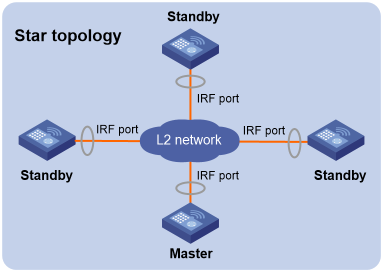
Star-topology IRF
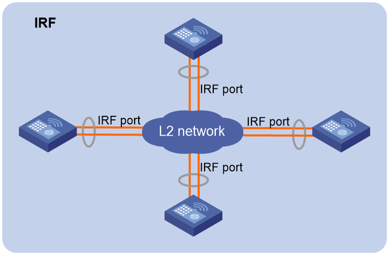
As shown in Figure 3, member devices of a star-topology IRF fabric are connected through a Layer 2 network. If you have only two IRF members, you can also connect them directly. The member devices can communicate with one another as long as they have Layer 2 connectivity.
Figure 3 Star-topology IRF network diagram
Benefits
Start-topology IRF provides the same benefits as ring-topology and daisy-chain IRF, including:
· Simplified topology and easy management—An IRF fabric appears as one node and is accessible at a single IP address on the network. You can use this IP address to log in at any member device to manage all the members of the IRF fabric.
· Simplified network operation—Various control protocols run on different member devices as if they were running on one device. For example, routing protocols regards the entire IRF fabric as one node when they calculate routes. This decreases the number of protocol packet exchanges on the network, simplifies network operation, and accelerates network convergence.
· 1:N redundancy—In an IRF fabric, one member acts as the master to manage and control the entire IRF fabric. All the other members process services while backing up the master. When the master fails, all the other member devices elect a new master from among them to take over without interrupting services.
· Star topology—The IRF member devices are connected in star topology through a Layer 2 network. Service traffic and IRF protocol packets are delivered between member devices over existing physical links. You do not need to use dedicated physical links to connect IRF member devices.
· IRF link redundancy—You can assign several links to an IRF port for redundancy. You do not need to aggregate the links. The IRF technology removes the loop automatically.
· Multichassis link aggregation—You can use the Ethernet link aggregation feature to aggregate the physical links between the IRF fabric and its upstream or downstream devices across the IRF members.
· Network scalability and resiliency—Processing capacity of an IRF fabric equals the total processing capacities of all the members. You can add and remove IRF member devices as needed without causing network topology change.
Implementation of star-topology IRF in WLAN
Concepts
IRF member roles
IRF uses two member roles: master and standby.
When devices form an IRF fabric, they elect a master to manage and control the IRF fabric, and all the other devices back up the master. When the master device fails, the remaining devices automatically elect a new master.
IRF port
An IRF port is a logical interface that forwards data and IRF control packets between IRF member devices. Every IRF-capable device has one IRF port. The IRF port is named in irf-port n format, where n is the IRF member ID of the device.
An IRF port must contain a minimum of one channel to send data and control packets.
IRF links
Links of the network interfaces bound to IRF ports are called IRF links.
You can configure an IRF link as one of the following channels:
· Control channel—The link forwards only IRF control packets between member devices.
· Data channel—The link forwards only data packets between member devices.
· Hybrid channel—The link forwards both control and data packets.
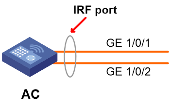
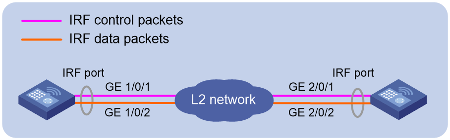
As shown in Figure 4, GigabitEthernet 1/0/1 and GigabitEthernet 1/0/2 are IRF network interfaces bound to the IRF port.
Figure 4 IRF port and IRF network interfaces
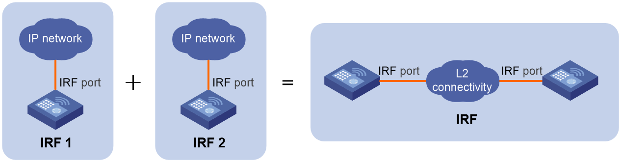
IRF merge
IRF merge occurs when two split IRF fabrics reunite or when two independent IRF fabrics are united, as shown in Figure 5.
Figure 5 IRF merge
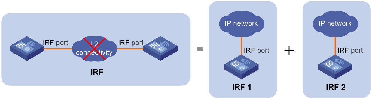
IRF split
IRF split occurs when an IRF fabric breaks up into multiple IRF fabrics when Layer 2 connectivity is lost, as shown in Figure 6. The split IRF fabrics operate with the same IP address. IRF split causes routing and forwarding problems on the network.
Figure 6 IRF split
Member priority
Member priority determines the possibility of a member device to be elected the master. A member with higher priority is more likely to be elected the master. By default, the member priority is 1.
Configuration synchronization
IRF configuration synchronization includes batch synchronization at initialization and real-time synchronization in steady operation.
· Batch synchronization:
When multiple devices build an IRF fabric, they first elect a master. The master synchronizes its running configuration to all standby devices. When a new member joins the IRF fabric during the runtime, the master also performs batch synchronization. The new member restarts and joins the IRF fabric as a standby device. Then the master synchronizes its running configuration in batches to the new member. The new member initializes with the synchronized configuration, without reading its local startup configuration file.
· Real-time synchronization:
After all member devices initialize, the IRF fabric operates as a single device in the network. You can log in to any IRF member device through the console port or through Telnet to manage and configure the IRF fabric. Whichever member device you attempt to log in, the master handles your request and places you at its CLI. All settings that you configure at the CLI of the master are automatically propagated to the IRF members.
IRF multi-active detection
An IRF link failure causes an IRF fabric to split in two IRF fabrics operating with the same Layer 2 and Layer 3 settings, including the same MAC and IP addresses. To avoid MAC and IP address collision and network issues, IRF uses multi-active detection (MAD) mechanisms to detect the presence of multiple identical IRF fabrics, handle collisions, and recover from faults.
Star-topology IRF provides MAD mechanisms by extending LACP, ARP, and IPv6 ND to detect multi-active collisions.
Choose a MAD mechanism depending on the network conditions:
· If the IRF member devices are connected to devices that support extended LACP, you can use LACP MAD.
· If the IRF member devices are connected to devices that do not support extended LACP or multichassis link aggregation, use ARP MAD on an IPv4 network and use ND MAD on an IPv6 network.
|
|
NOTE: Do not use LACP MAD with ARP MAD or ND MAD, because they handle collisions differently. |
IRF software auto-update
IRF provides the software auto-update feature. With this feature, you do not need to manually update a device with the software version running on an IRF fabric before you add the device to the IRF fabric. The device will automatically update the software as long as its software version is compatible with the one running on the IRF fabric, as follows:
When you add the device to the IRF fabric, the device compares its software version with that of the master. If the versions are not the same, it automatically downloads startup software images from the master, reboots with the new startup software images, and joins the IRF fabric again.
If the device does not support software auto-update, you must manually update it with the software version running on the IRF fabric before you add it to the IRF fabric.
High availability technologies
· Protocol hot backup.
· Uplink and downlink redundancy.
· IRF link redundancy.
· Separation of data and control channels.
· License sharing.
Protocol hot backup
In an IRF fabric, the master device synchronizes the following information to all the other member devices:
· Protocol configuration.
· Data for a protocol to run, including state machine data and session table entries.
· Information about APs and clients regarding their access, authentication, and state.
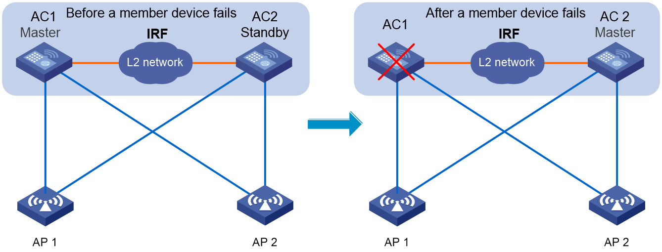
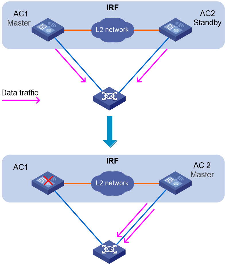
As shown in Figure 7, AP 1 accesses the master (AC 1) and AP 2 accesses the standby device (AC 2). The master AC participates in the access of all APs. The standby AC synchronizes the access information of AP 2 and stations to the master AC. After receiving the information, the master AC synchronizes its local AP and station access information together with the received information to the standby AC.
When the master fails, the new master can take the responsibility of the old master seamlessly. Upon receiving new access information, the master sends the updated access information and protocol state information to all the other member devices. The running of the entire IRF fabric is not affected. In this way, when a member device fails, the other member devices can operate correctly and can quickly take the responsibility of the failed member device. In addition, the intra-domain system information and protocol processing will not be interrupted, and Layer 2 and Layer 3 forwarding traffic and services will not be interrupted either. With protocol hot backup of IRF, fault protection and device switching can be implemented without service interruption.
Figure 7 Protocol hot backup diagram
Uplink and downlink redundancy
IRF supports multichassis link aggregation to aggregate Ethernet links from multiple IRF member devices to a downstream or upstream device for node redundancy. When one member fails, traffic can be distributed across the remaining links connected to the remaining member devices, as shown in Figure 8.
Figure 8 Multichassis link aggregation for node redundancy
IRF link redundancy
As shown in Figure 9, you can use multiple links to convey the IRF control channel and data channel for increased bandwidth and redundancy. IRF can function correctly as long as the control and data channels each have one link.
|
|
NOTE: To avoid loops, you must configure the peer ports on the L2 switch that connect to an IRF member device as follows: · If you are deploying separate control and data channels, assign each port to a unique VLAN as a best practice. · If you are deploying a hybrid channel, aggregate the ports into a static aggregation or assign each port to a unique VLAN. On the IRF fabric, automatic loop avoidance mechanisms are available. You do not need to manually aggregate links bound to the IRF port or assign them to VLANs. |
Figure 9 IRF port backup diagram
IRF data and control channel separation
You can configure an IRF link as one of the following channels:
· Control channel—The link forwards only IRF control packets between member devices.
· Data channel—The link forwards only data packets between member devices.
· Hybrid channel—The link forwards both control and data packets.
As a best practice, use separate physical links as data and control channels to improve network security.
Figure 10 IRF data and control channel separation diagram
License sharing
The ACs in an IRF fabric share their licenses. The licenses running before a master/standby switchover continue to take effect after the switchover.
Deployment models
An AC comes in the form of a standalone device or a service module.
The following are typical deployments for AC devices or AC modules:
· IRF fabric of Layer 2 network connected AC devices
· IRF fabric of directly connected two ACs
· AC module IRF fabric hosted in chassis
If you connect the AP-side network interfaces on an AC IRF fabric to devices incapable of multichassis link aggregation, use the independent port model, as described in "Independent port model."
IRF fabric of Layer 2 network connected AC devices
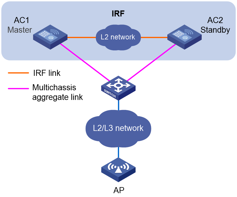
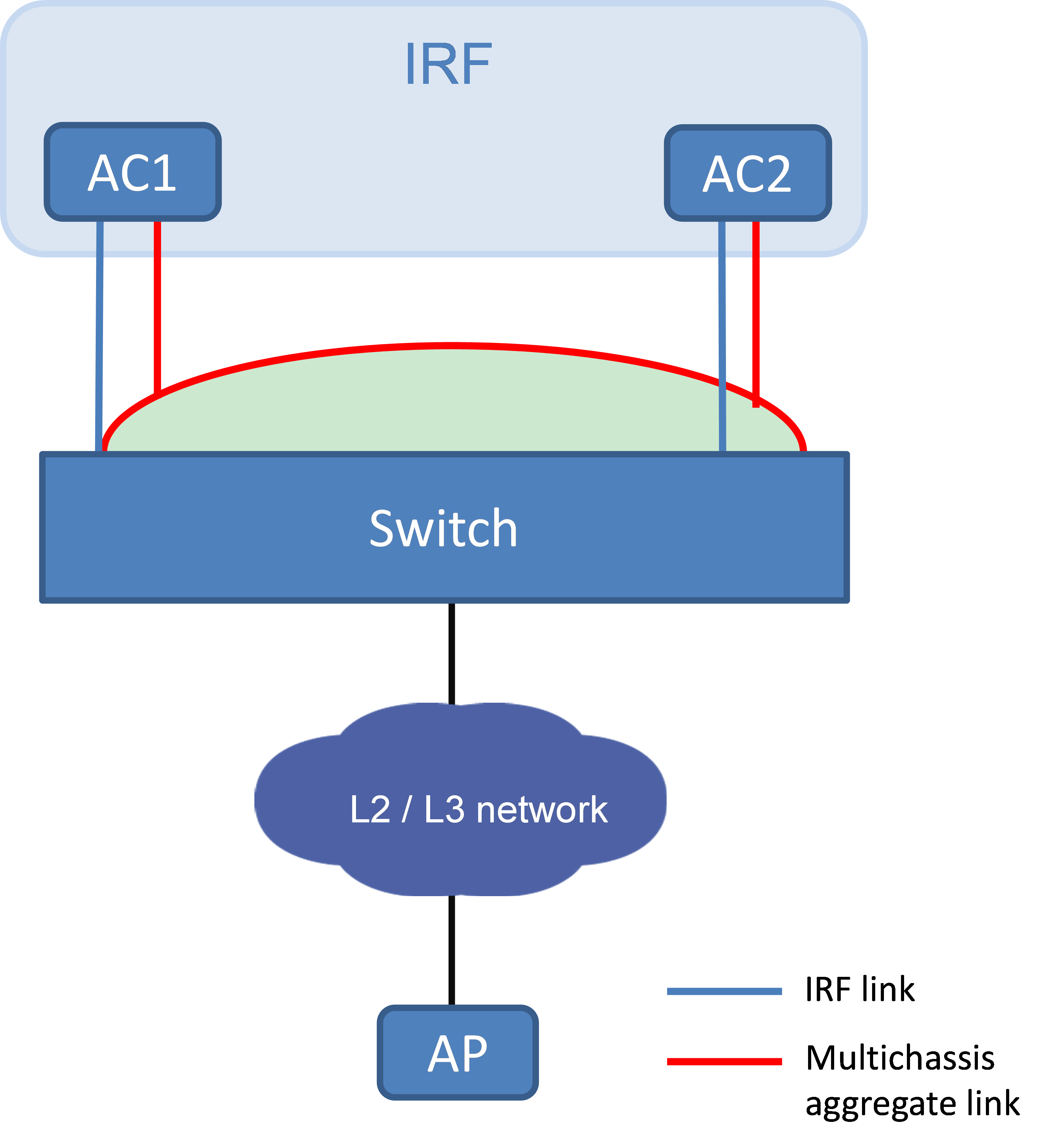
In this deployment, you set up an IRF connection between two AC devices over a switch and establish a dynamic dual-AC downlink aggregation with the switch, as shown in Figure 11. On the switch, assign the IRF link and the multichassis aggregate link to different VLANs.
Figure 11 IRF fabric of Layer 2 network connected AC devices
IRF fabric of directly connected two ACs
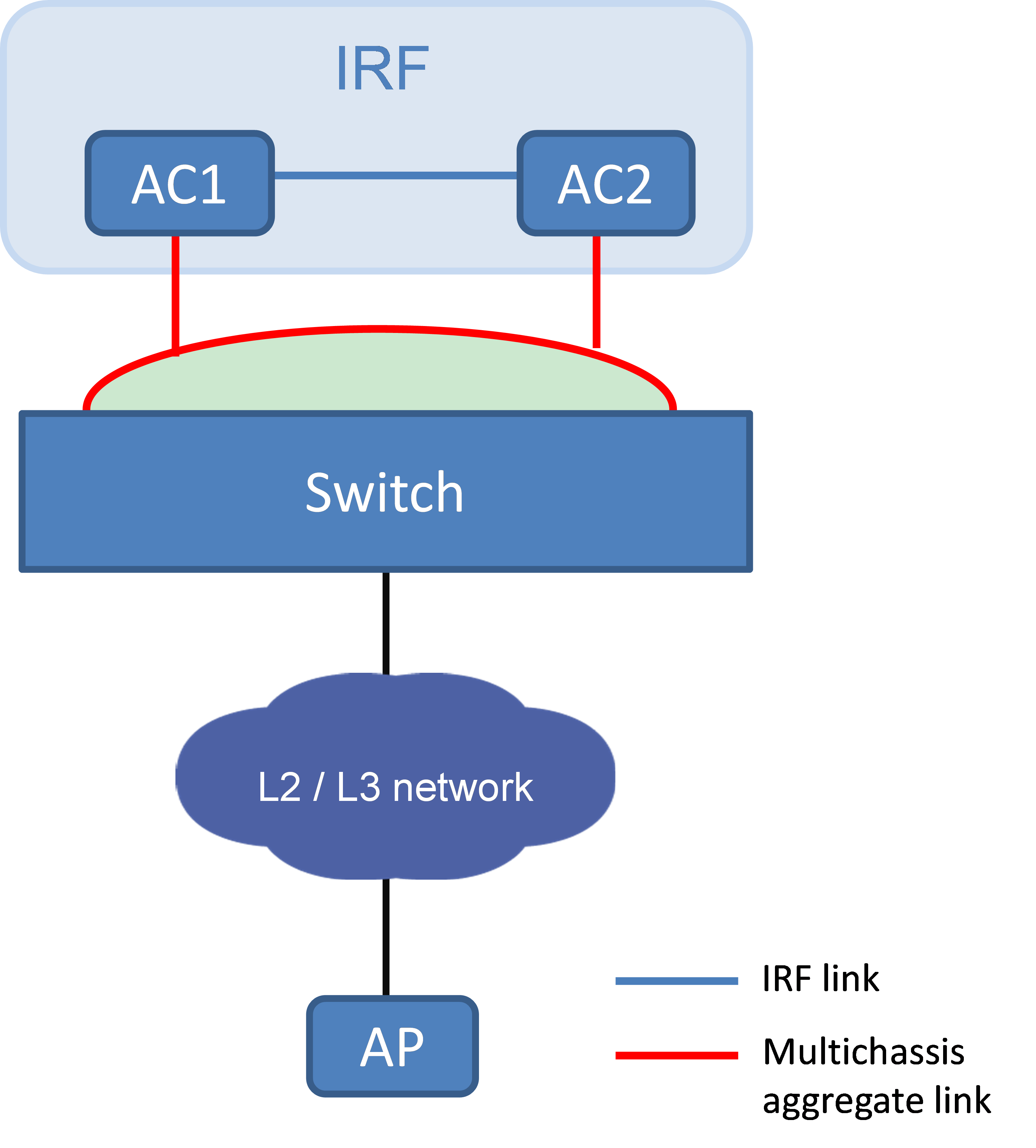
In this deployment, you set up a direct IRF connection between two AC devices and establish a dynamic dual-AC link aggregation with the remote switch, as shown in Figure 12.
Figure 12 IRF fabric of directly connected two ACs
AC module IRF fabric hosted in chassis
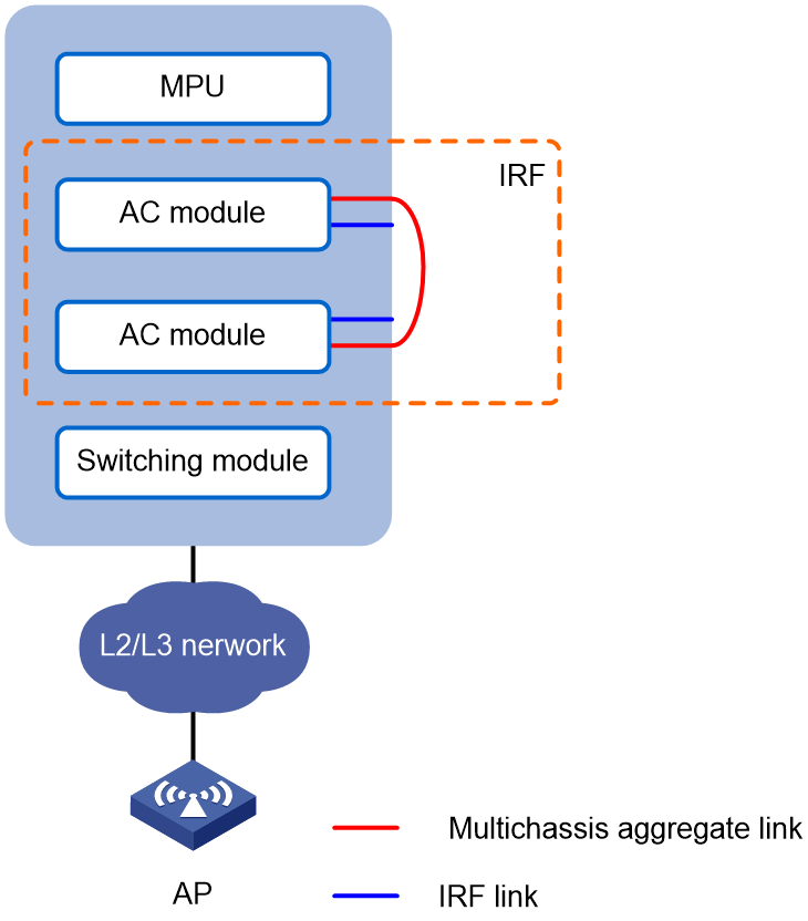
In this deployment, you install two AC modules in a switch chassis and establish an IRF connection between their internal ports, as shown in Figure 13.
In addition, use the remaining internal ports of the AC modules to establish a dynamic link aggregation for user connectivity with the chassis.
To isolate traffic, assign the IRF link and the aggregate link for user connectivity to different VLANs.
Figure 13 AC module IRF fabric hosted in a chassis
You can also install the AC modules in different chassis in a switch IRF fabric to establish an AC IRF fabric.
Independent port model
This deployment model is suitable for the IRF fabric connected to third-party devices incapable of multichassis aggregation. As shown in Figure 14, the AP-side network interfaces on the two AC devices are connected to different standalone switches without being aggregated.
To isolate traffic, assign the IRF links and the AP-side network links to different VLANs.
To eliminate loops, run the spanning tree feature between the IRF fabric and the L2 switches.
Figure 14 Independent port model
Application scenarios
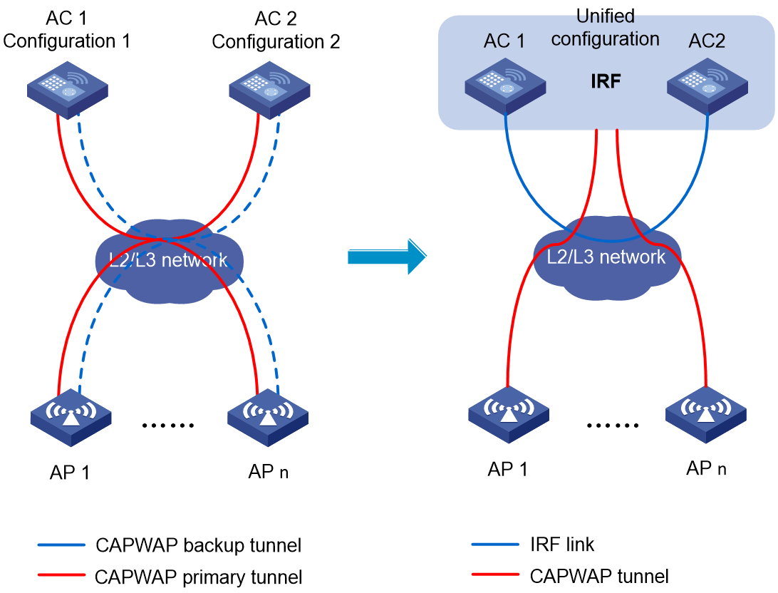
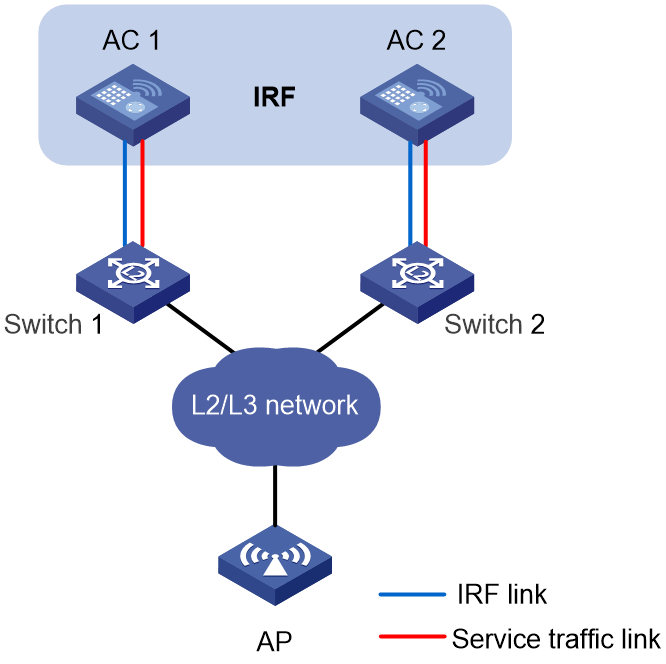
Replacing traditional dual-AC link backup with star-topology IRF
Traditional dual-AC link backup solution provides link redundancy by dual-homing each AP to two standalone ACs to set up primary and backup CAPWAP tunnels. This solution is complex in that you have to configure and maintain CAPWAP tunnels on both ACs.
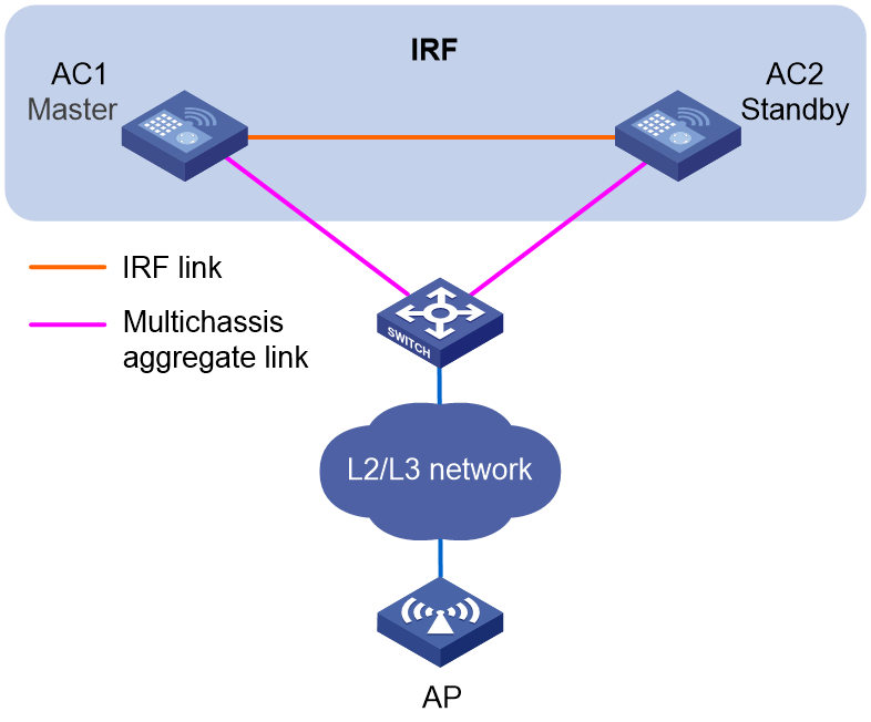
To streamline the topology and decrease administrative complexity, virtualize the ACs into one IRF fabric in star topology, as shown in Figure 15. This solution provides node and link redundancy, but it requires each AP to establish only one set of control and data CAPWAP tunnels with the AC IRF fabric. In addition, you can manage and configure the IRF fabric as a whole instead of having to access the ACs one by one.
Figure 15 Replacing traditional dual-AC link backup with star-topology IRF