- Released At: 16-10-2023
- Page Views:
- Downloads:
- Table of Contents
- Related Documents
-
|
|
|
|
|
NAT Technology White Paper |
|
|
|
|
Copyright © 2021 New H3C Technologies Co., Ltd. All rights reserved.
No part of this manual may be reproduced or transmitted in any form or by any means without prior written consent of New H3C Technologies Co., Ltd.
Except for the trademarks of New H3C Technologies Co., Ltd., any trademarks that may be mentioned in this document are the property of their respective owners.
This document provides generic technical information, some of which might not be applicable to your products.
The information in this document is subject to change without notice.
Contents
Private hosts access a public network server
Public hosts access an internal server
Private hosts access an internal server using its domain name
Overview
Technical background
With the fast growth of the Internet, the IPv4 address depletion problem has become a bottleneck for network development, but IPv6 adoption is slow. Before IPv6 is widely used, Network Address Translation (NAT) can map private IP addresses to public IP addresses. It alleviates the depletion of IPv4 addresses and ensures network communication.
Benefits
As a transition technology, NAT solves the IP address depletion issue by allowing pubic IP addresses to be reused. It has the following functions and advantages:
· Translates between private IP addresses and public IP addresses.
· Translates multiple private IP addresses into a single public IP address with different port numbers.
· Maps several internal server addresses to a public IP address in static entries. An external user can use the public address and port number to access an internal server. At the same time, the real IP address of the internal server is hidden from the outside for attack prevention.
· Facilitates network management. With NAT, you can move an internal server to another place by modifying the corresponding address mapping entry, and tune the internal network easily.
NAT implementation
Concepts
The following describes basic NAT concepts:
· NAT device—A device configured with NAT. Typically, NAT is configured on the edge device that connects the internal and external networks.
· NAT rule—Specifies the NAT configuration used for address translation.
· NAT address—A public IP address used for address translation, and this address is reachable from the external network. The NAT address can be manually assigned or dynamically obtained.
· NAT entry—Stores the mapping between a private IP address and a public IP address.
· Easy IP—Uses the IP address of an interface as the NAT address. The IP address of the interface can be manually assigned or be obtained through DHCP.
Mechanism
The basic function of NAT is to assign a private host a public address to access the Internet. The private host uses a private IP address for communication within the internal network. Upon receiving a packet destined to the Internet, the NAT device translates the source IP address in the header into a valid public IP address and records the entry. When a reply is returned from the Internet, the NAT device translates the public destination address of the packet into the private address of the sending host based on the recorded NAT entry, and then, forwards the packet to the host. The whole process is transparent to both the private network and public network. NAT can save numerous public IP addresses for the internal hosts to access the Internet.
NAT translation methods
Static NAT
Static NAT creates a fixed mapping between a private address and a public address. It supports connections initiated from internal users to external network and from external users to the internal network. Static NAT applies to regular communications.
NO-PAT
Not Port Address Translation (NO-PAT) refers to one-to-one NAT, which translates only IP addresses without TCP/UDP port numbers and thus one public IP address cannot be used by multiple private users.
Figure 1 Network diagram for NO-PAT
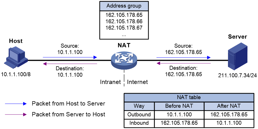
As shown in Figure 1, basic NAT works as follows:
1. The NAT device receives a packet from a host on the private network to a server on the public network.
2. The NAT device selects a free public IP address from the address pool, and records the outbound and inbound mappings between the source IP address of the packet and the public IP address. Then, it performs address translation based on the outbound NAT entry and sends the packet out.
3. Upon receiving a reply from the public network, the NAT device searches the inbound NAT entry to translate the public destination IP address in the packet into the private address of the host, and forwards the packet towards the private network.
PAT
NO-PAT does not allow multiple private hosts to use a single public IP address, and thus cannot effectively solve the IP address depletion issue. Port Address Translation (PAT) can solve the problem.
PAT translates multiple private IP addresses to a single public IP address by mapping the private IP address and source port to the public IP address and a unique port. It is the most commonly used NAT function. PAT supports TCP and UDP packets, and ICMP request packets.
Figure 2 Network diagram for PAT
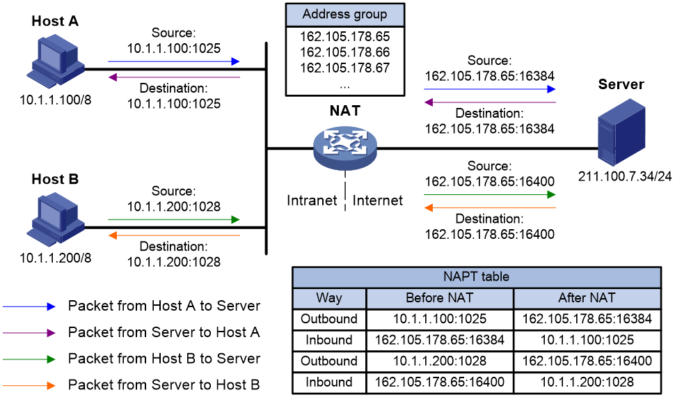
As shown in Figure 2, PAT works as follows:
1. The NAT device receives a packet from a private host to a public server.
2. The NAT device selects a free public IP address and a port number from the address pool and map them to the source IP address and source port number of the packet (both inbound and inbound). Then, it forwards the packet towards the public network after performing PAT translation based on the outbound PAT entry.
3. Upon receiving a reply from the public network, the NAT device uses the inbound PAT entry to translate the public destination IP address and port number in the packet into the private address and port number of the host, and forwards the packet towards the private network.
NAT Server
Generally, for security, public hosts are not allowed to access any server on a private network. However, in special cases, public hosts need to access some internal servers. NO-PAT and PAT cannot create NAT entries for requests initiated from the public network. To solve this problem, you can map the private IP address and port number of an internal server to a public IP address and port number, so that the NAT device can process access requests from the public network.
Figure 3 Network diagram for accessing a NAT server
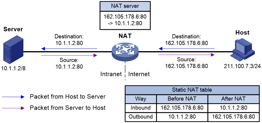
As shown in Figure 3, the internal server feature is implemented on the NAT device as follows:
1. The NAT device receives an access request from a public host to the internal server.
2. The NAT device looks for the static NAT entry containing the public destination IP address and port number in the request, translates them into the corresponding private address and port number of the server, and forwards the request towards the private network side.
3. Upon receiving a reply from the private network side, the NAT device looks for the static entry containing the source IP address and port number in the reply, translates them into the corresponding public IP address and port number and forwards the reply to the public network side.
Easy IP
Easy IP allows a NAT device to directly use the public IP address of its outgoing interface as the post-NAT source address of packets from an internal LAN. The outgoing interface usually obtains its public IP address through dial-up or DHCP.
Easy IP enables hosts in small LANs, such as small-to-medium scale cyber cafes and small scale office networks, to access the Internet.
Figure 4 Network diagram for Easy IP
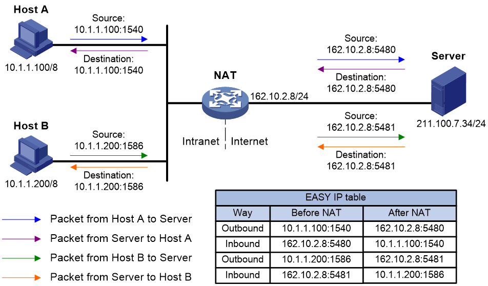
As shown in Figure 4, Easy IP works as follows:
1. The NAT device receives a packet from a private host to a public server.
2. The NAT device creates inbound and outbound Easy IP entries for the packet and uses the outbound entry to replace the source IP address and source port number of the packet with the public IP address of its outgoing interface and a public port number. Then, it forwards the packet towards the public network.
3. Upon receiving a reply from the public network, the NAT device uses the inbound Easy IP entry to translate the public destination IP address and port number in the packet into the private address and port number, and forwards the packet towards the private network.
NAT hairpin
NAT hairpin allows internal hosts to access each other through NAT. The source and destination IP address of the packets are translated on the interface connected to the internal network.
NAT hairpin includes P2P and C/S modes:
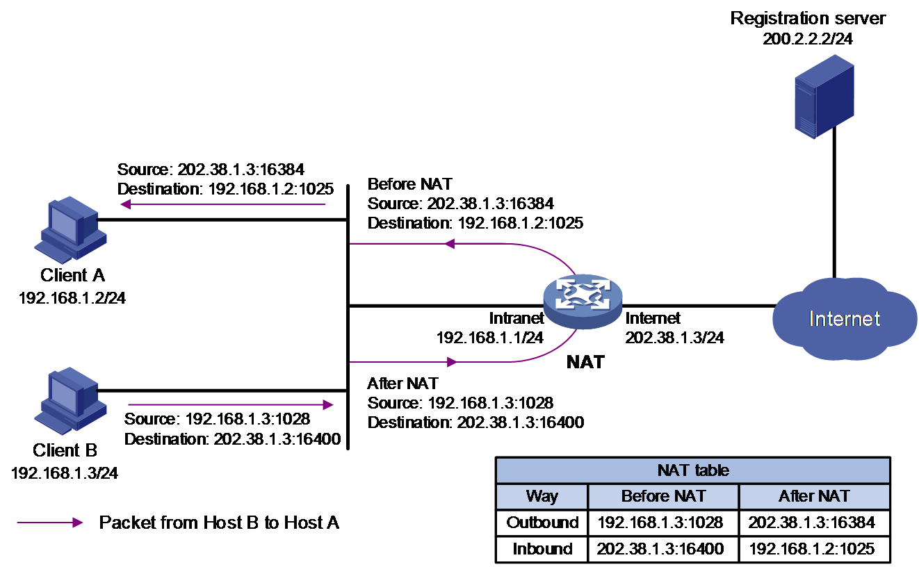
· P2P—Allows internal hosts to access each other through NAT. The internal hosts first register their public addresses and ports after NAT to an external server. As shown in Figure 5 and Figure 6, the internal hosts communicate with each other by using the registered IP addresses and ports from the external server.
Figure 5 NAT hairpin in P2P mode (packets from Host A to Host B)
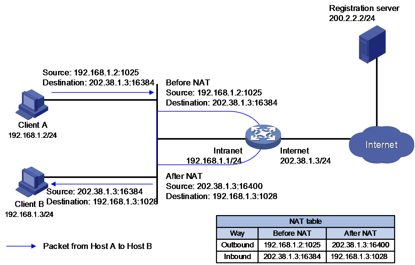
Figure 6 NAT hairpin in P2P mode (packets from Host B to Host A)
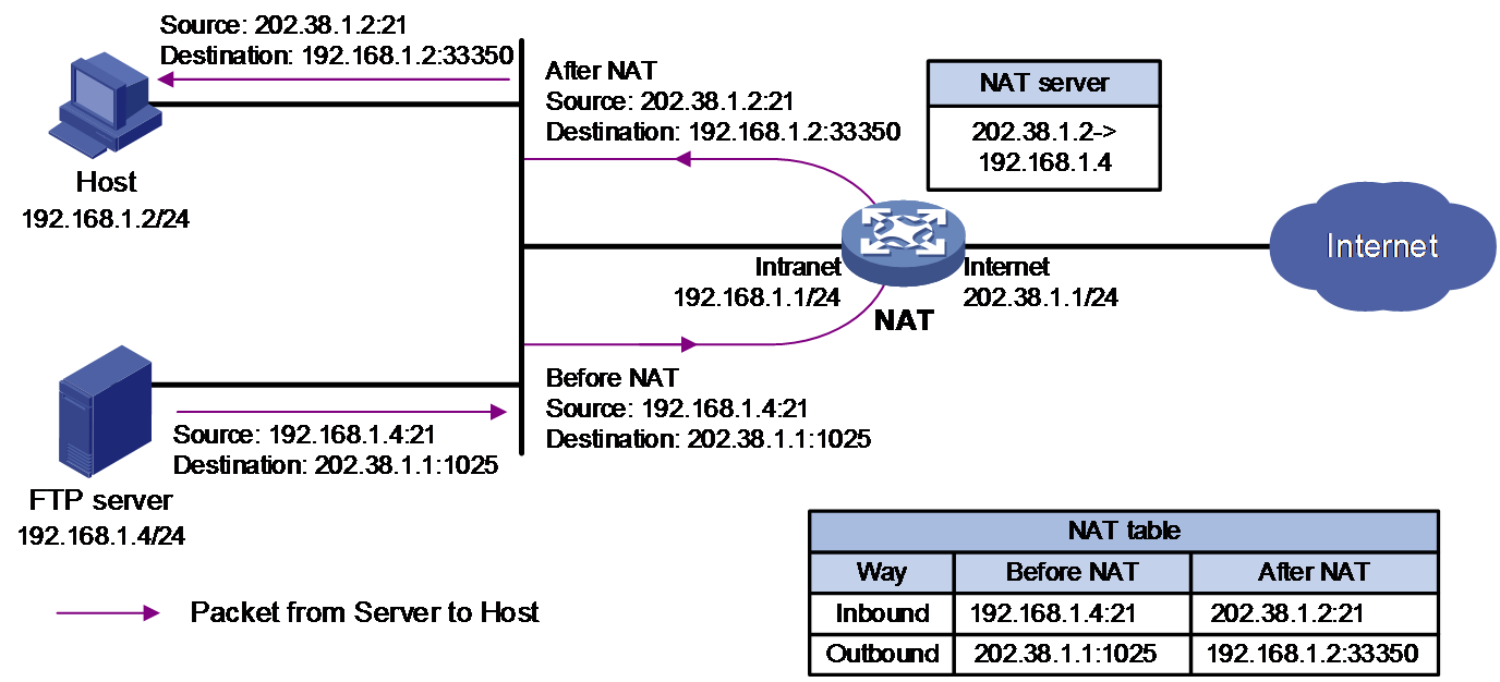
· C/S—Allows internal hosts to access internal servers through NAT addresses. As shown in Figure 7 and Figure 8, an internal user initiates a connection to the FTP server on the same private network. The destination IP address of the packet going to the internal server is translated by matching the NAT Server configuration. The source IP address is translated by matching the outbound dynamic or static NAT entries.
Figure 7 NAT hairpin in C/S mode (Packets from Host to Sever)
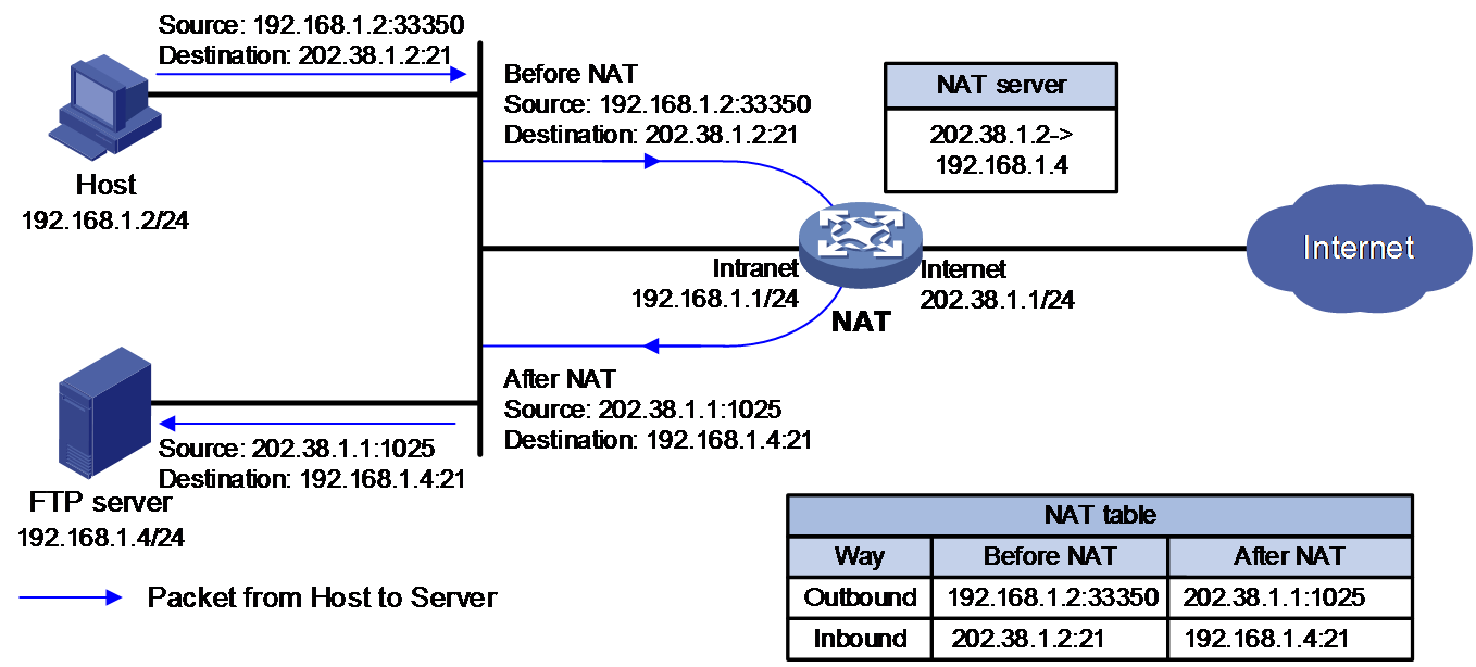
Figure 8 NAT hairpin in C/S mode (Packets from Server to Host)
NAT ALG
Introduction
Typically, NAT only translates IP addresses and port numbers in IP headers; however, messages of some application layer protocols contain address or port number information in the payload, which also needs translation. For instance, a server may need to negotiate a port number with a client before initiating a connection. If the NAT device does not know the negotiated port number, it cannot perform translation for the packet the server sends to the client, causing a connection failure.
The application layer gateway (ALG) mechanism can solve the above problem. ALG is used to process packets of application layer protocols. It translates the IP addresses or port numbers contained in the payload of some protocol messages, allowing them to transit. The application layer protocols that NAT supports include: Domain Name System (DNS), File Transfer Protocol (FTP), H.323, Internet Locator Service (ILS), and Session Initiation Protocol (SIP).
Concepts
· Session—Records the information carried in transport layer packets, including the source IP address, source port, destination IP address, destination port, protocol type, and VPN instance to which the source/destination IP address belongs.
· Dynamic channel—The address information carried by a packet of an application layer protocol can be used to establish a dynamic channel, and subsequent connections that match the address information will transmit data through the dynamic channel.
ALG for FTP
In an FTP operation, two TCP connections are established between the client and server, namely, a control connection and a data connection. The control connection transmits control information such as user commands and parameters, including the port information used for initiating the data connection. The data connection forms a data channel between the server and client to transmit files. The need of performing ALG is based on the FTP mode (active or passive) and the locations of the server and client.
Active mode
In FTP active mode, the client issues a PORT command containing the specified port number over the control connection to the server, which then initiates a data connection to the specified port. In this mode, whether to use ALG depends on where the client and the server locate. Therefore,
· If the client locates on the public network and the server locates on the private network, the client provides a public IP address and port number to the server, which can directly initiate a data connection to the client without ALG.
· If the client locates on the private network and the server locates on the public network, the client provides a private IP address and port number to the server. Then, ALG is used to translate them into a public IP address and port number, which the server uses to initiate a data connection to the client, as shown in Figure 9.
Figure 9 ALG in FTP active mode
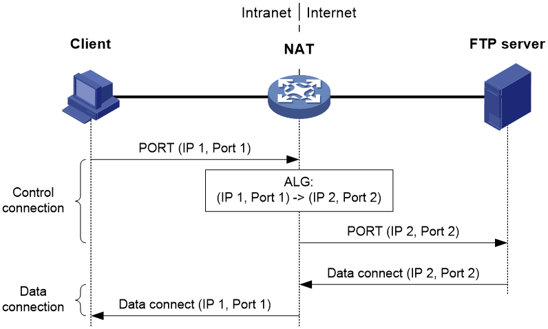
In active mode, FTP ALG works as follows:
1. The client issues a PORT command containing the IP address and port number (IP 1, Port 1) to the server through the NAT device, which is configured with ALG.
2. Upon receiving the command, the NAT device translates the private IP address and port number (IP 1, Port 1) in the payload into a public IP address and port number (IP 2, Port 2), and then creates a PAT entry. This procedure is ALG processing.
3. Upon receiving the command, the server initiates a data connection to the public IP address and port number (IP 2, Port 2) which will be translated into (IP 1, Port 1) by the NAT device.
Passive mode
In FTP passive mode, the client sends a PASV request over the control connection to the server, which then returns a PASV reply containing the specified port to the client. After that, the client initiates a data connection to the specified port of the server. In this mode, whether to use ALG depends on where the client and the server locate. Therefore,
· If the server locates on the public network and the client locates on the private network, the server provides a public IP address and port number to the client, which can directly initiate a data connection to the server without ALG.
· If the server locates on the private network while the client locates on the public network, the server provides a private IP address and port number to the client. Then, ALG is used to translate them into a public IP address and port number, which the client uses to initiate a data connection to the server, as shown in Figure 10.
Figure 10 ALG in FTP passive mode
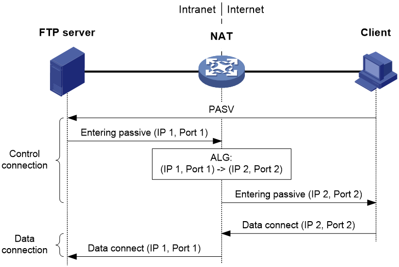
In passive mode, FTP ALG works as follows:
1. The client sends a PASV request to the server.
2. Upon receiving the request, the server chooses an IP address and port number (IP 1, Port 1) for establishing a data channel and sends them in a PASV reply to the client.
3. Upon receiving the reply, the NAT device, which is configured with ALG, translates the private IP address and port number (IP 1, Port 1) in the payload into a public IP address and port number (IP 2, Port 2), creates an PAT entry and sends the reply to the client. This procedure is called ALG processing.
4. Upon receiving the reply, the client initiates a data connection to the public IP address and port number (IP 2, Port 2), which will be translated into (IP 1, Port 1) by the NAT device.
ALG for DNS
As shown in Figure 11, a Web server in the internal network provides services for external users. A DNS server is used to resolve the domain name of the Web server. To access the Web server, the internal host requests for the private IP address by the domain name. The DNS server replies with a response packet with the public IP address of the Web server in the payload. To avoid the network issue, configure NAT DNS mapping and ALG configuration so that the public IP address can be translated to the private one.
Figure 11 ALG processing the DNS packet payload
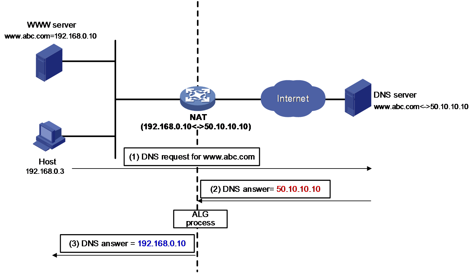
ALG for DNS processes DNS packets as follows:
1. The internal host sends a name query to the external DNS server for the IP address of the Web server.
2. The DNS resolver looks up the local domain name cache for a match. The resolver sends the corresponding IP address (50.10.10.10) back, which cannot be used for internal users to access the Web server.
3. The NAT server configured with DNS mapping and ALG translates the public address (50.10.10.10) to the private IP address (192.168.0.10) in the payload of the DNS response packet. That is, the NAT device replaces IP address 50.10.10.10 in the DNS packet payload with 192.168.0.10 and then sends the DNS response packet to the private host.
4. The internal host can access the Web server by using its domain name after receiving the response packet.
ALG for ICMP
As shown in Figure 12, the FTP server is on the private network, and the host is on the public network. The host wants to access the FTP server. If port 21 of the FTP server is not open, it sends an ICMP error packet to the host upon receiving the request. If the NAT device has not been configured with ALG, the host on the public network cannot identify the application of the packet. At the same time, the private IP address of the FTP server is revealed. To avoid the network issue, configure ALG on the NAT device so that the public IP address can be translated to the private one.
Figure 12 ALG processing the ICMP error packet payload
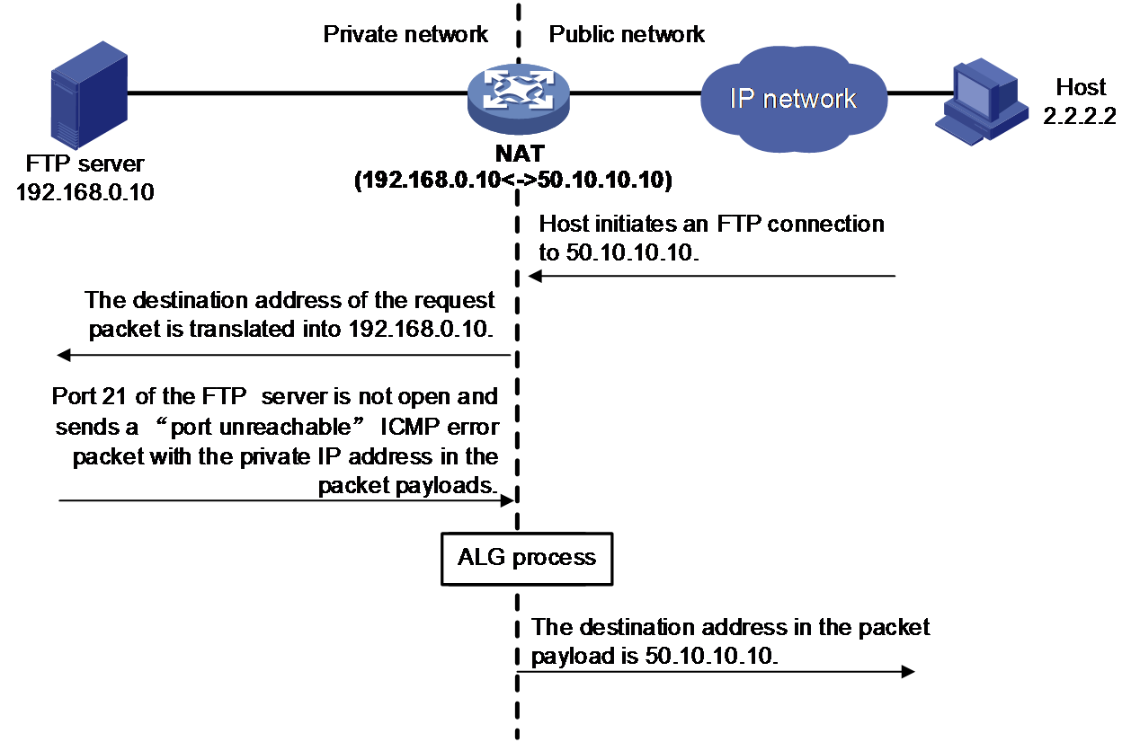
ALG for ICMP processes ICMP packets as follows:
1. The external host initiates a connection to the FTP server, whose public address is 50.10.10.10.
2. The NAT device translates the destination IP address of the packet to the private IP address 192.168.0.10. NAT creates a NAT session entry and creates an address mapping for the packet in the session.
3. The port 21 of the FTP server is not open, it sends an ICMP error packet to the host upon receiving the request. The IP address in the ICMP error packet payload is a private IP address.
4. When the ICMP error packet arrives at the NAT device, ALG translates private address 192.168.0.10 in the payload back to public address 50.10.10.10 according to the FTP address translation record and then sends the ICMP packet to the public network.
Therefore, the host on the public network can correctly identify the faulty application program, and prevent private address leakage.
DNS mapping
DNS mapping performs as a work-around for a typical network typology with traditional NAT ALG. As shown in Figure 13, the DNS server is typically on the public network. The NAT device maps multiple private IP addresses to a single public IP address. A private client contacts the public DNS server to resolve the domain name of the Web server. The NAT device cannot translates the public IP address in the payload to the corresponding private IP address correctly for the multiple-to-one mapping.
To solve this address translation problem, NAT DNS mapping can be used to map the domain name of an internal server to the public IP address, public port number, and protocol type of the internal server. NAT Server maps the public IP and port to the private IP and port of the internal server.
Figure 13 Network diagram for DNS mapping
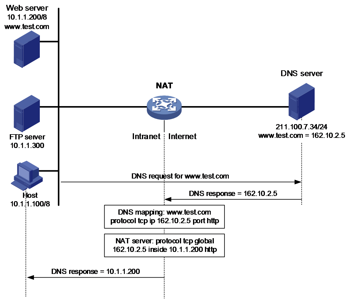
NAT DNS mapping works as follows:
1. The internal host sends a DNS request containing the domain name (www.test.com) of the internal Web server.
2. Upon receiving the DNS response, the NAT device performs a DNS mapping lookup by using the domain name in the response. A NAT DNS mapping maps the domain name to the public IP address, public port number, and the protocol type for the internal Web server.
3. If a match is found, the NAT continues to compare the public address, public port number, and the protocol type with the NAT Server configuration. The NAT Server configuration maps the public IP address and port number to the private IP address and port number for the internal Web server.
4. If a match is found, NAT translates the public IP address in the response into the private IP address of the Web server.
5. The internal host receives the DNS response, and obtains the private IP address of the Web server.
VRF-aware NAT
This feature allows users from different MPLS L3VPNs to access external networks or provide services to external networks. It also allows them to use the same private IP address segment. To achieve these purposes, VRF-aware NAT identifies sessions from different VPNs by using VPN information.
VRF-aware NO-PAT
Similar to non-VRF-aware NAT, VRF-aware NO-PAT only translates private IP addresses. In addition, it can identify and process VPN information by adding VPN information to NAT entries, so that the same private IP addresses of different VPNs can be translated into different public IP addresses.
VRF-aware PAT
Compared with non-VRF-aware PAT, VRF-aware PAT can identify and process VPN information when translating private IP addresses and port numbers. In this way, the same private IP addresses and port numbers of different VPNs can be translated into different public IP addresses and port numbers.
VRF-aware NAT internal server
Compared with non-VRF-aware NAT internal server, VRF-aware NAT internal server can identify and process VPN information when translating the IP address and port number for an internal server in a VPN. To achieve this, it adds VPN information to the static NAT entry of the server. In this way, packets sent to internal servers in different VPNs can be forwarded correctly.
VRF-aware Easy IP
Compared with non-VRF-aware Easy IP, VRF-aware Easy IP can identify and process VPN information when translating private IP addresses and port numbers. To achieve this, it adds VPN information to Easy IP entries. In this way, the same private IP addresses and port numbers of different VPNs are translated into different public IP addresses and port numbers.
VRF-aware DNS mapping
Compared with non-VRF-aware DNS mapping, VRF-aware DNS mapping can identify and process VPN information when translating private IP addresses and port numbers. To achieve this, it adds VPN information to the DNS mapping entries. In this way, packets sent to different VPNs are forwarded correctly.
VRF-aware ALG
Compared with non-VRF-aware NAT ALG, VRF-aware NAT ALG can identify and process VPN information while translating private IP addresses and port numbers. To achieve this, it adds VPN information to NAT entries. For instance, the private network information (VPN A, IP 1, Port 1) can be mapped to the public network information (IP 2, Port 2).
Application scenarios
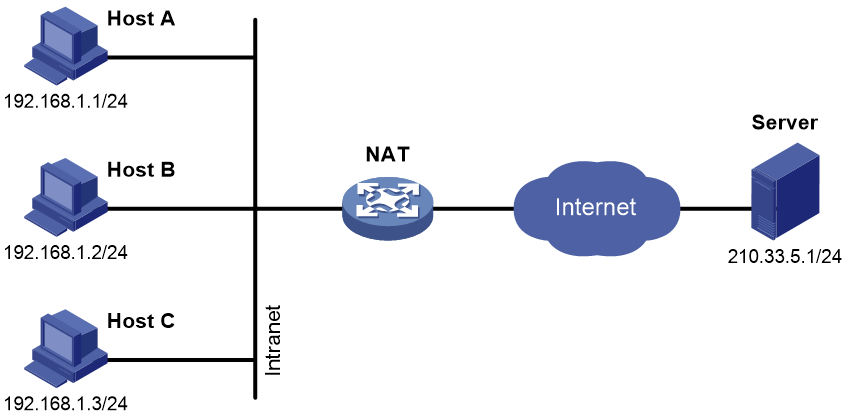
Private hosts access a public network server
Since public network addresses are scarce, hosts in most residential, campus and enterprise networks use private IP addresses. In these scenarios, NAT can be used to allow them to access the Internet.
In Figure 14, configure address translation rules on the NAT gateway so that the private hosts can access the server on the public network.
Figure 14 Private hosts access a public network server
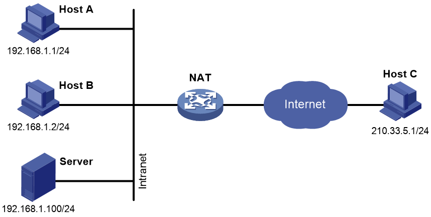
Public hosts access an internal server
The NAT internal server feature allows an internal server to provide WWW and FTP services to public hosts. In Figure 15, you can map a public IP address and port number to the private IP address and port number of the internal server on the NAT device, so that public hosts can access the internal server through the NAT device.
Figure 15 Public hosts access an internal server
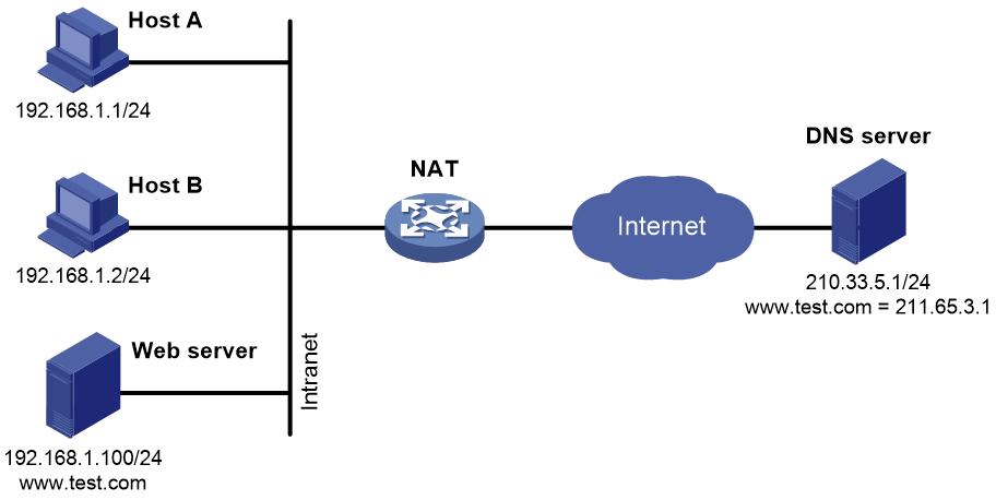
Private hosts access an internal server using its domain name
In some cases, a private user needs to access an internal server on the same private network by using its domain name when the DNS server is on the public network. DNS mapping can meet the requirement. As shown in Figure 16, you can specify the domain name, public IP address, public port number, and protocol type of the internal server in the DNS mapping table. The NAT device can use the DNS mapping to replace the public IP address in the DNS reply message with the private IP address of the internal server. As a result, the hosts can access the internal server using its domain name.
Figure 16 Private hosts access an internal server using its domain name
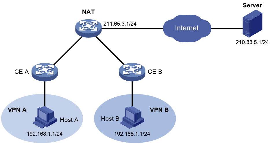
VRF-aware NAT
VRF-aware NAT allows two hosts in different MPLS VPNs to use the same private IP address to access the Internet. In Figure 17, Host A and Host B use the same private IP address but belong to different VPNs. Through VRF-aware NAT, Host A and Host B can access the public network server simultaneously.
Figure 17 Network diagram for VRF-aware NAT
References
· RFC 1631: The IP Network Address Translator (NAT)
· RFC 2663: IP Network Address Translator (NAT) Terminology and Considerations
· RFC 2993: Architectural Implications of NAT
· RFC 3022: Traditional IP Network Address Translator (Traditional NAT)
· RFC 3027: Protocol Complications with the IP Network Address Translator
