| Title | Size | Downloads |
|---|---|---|
| 802.11ax Technology White Paper-6W101-book.pdf | 459.12 KB |
- Table of Contents
- Related Documents
-
|
|
|
802.11ax |
|
Technology White Paper |
|
|
|
|
Copyright © 2022 New H3C Technologies Co., Ltd. All rights reserved.
No part of this manual may be reproduced or transmitted in any form or by any means without prior written consent of New H3C Technologies Co., Ltd.
Except for the trademarks of New H3C Technologies Co., Ltd., any trademarks that may be mentioned in this document are the property of their respective owners.
The information in this document is subject to change without notice.
Contents
Overview
Technical background
802.11ac and earlier WLAN protocols are targeted at improving the transmission rate instead of the network capacity. The popularization of wireless clients and applications has brought higher requirements on network capacity, especially in dense environments.
802.11ax is developed to resolve the issue by adopting series of new technologies and optimization methods to increase the access rate, high-density performance, and wireless coverage. It can meet the requirements of latency-sensitive applications such as instant messaging, AR/VR, and high-definition media services.
Benefits
802.11ax, also known as High-Efficiency Wireless (HEW), optimizes the physical layer and data link layer to improve concurrency performance, solving the low-throughput issue. It offers a minimum of four times throughput of 802.11ac in high-density scenarios.
802.11ax provides the following benefits:
· Improved concurrency performance—With OFDMA, spatial reuse, and uplink and downlink MU-MIMO, 802.11ax has greatly improved wireless performance in high-density scenarios.
· Highly reliable outdoor transmission—OFDMA further splits subcarriers to provide increased data rate compared with OFDM used by 802.11ac. Because of narrowed bandwidth, the transmission distance is also extended. With wider guard bands between groups of subcarriers, 802.11ax provides much better wireless coverage, transmission efficiency, and higher reliability than 802.11ac.
· Improved power efficiency—TWT reduces client wakeup times to greatly save power consumption, and spatial reuse enables on-demand transmit power adjustment to resolve co-channel interference and improve power efficiency.
Table 1 Comparison of 802.11ac and 802.11ax
|
Item |
802.11ac |
802.11ax |
|
Frequency band |
5 G |
5 G and 2.4 G |
|
Channel bandwidth (MHz) |
20, 40, 80, 160, 80+80 |
20, 40, 80, 160, 80+80 |
|
Modulation |
OFDM Highest modulation: 256-QAM |
OFDMA Highest modulation: 1024-QAM |
|
Subcarriers |
64 (20 MHz bandwidth) |
256 (20 MHz bandwidth) |
|
Guard intervals |
400 ns, 800 ns |
800 ns, 1600 ns, 3200 ns |
|
Maximum rate |
6.9 Gbps (1.7 Gbps supported by existing devices) |
9.6 Gbps (4.8 Gbps supported by existing devices) |
|
Max aggregation length |
1048575 bytes |
4194303 bytes |
|
Spatial multiplexing |
Not supported |
Supported |
|
OFDMA |
Not supported |
Supported |
|
MU-MIMO |
Downlink |
Uplink and downlink |
|
TWT |
Not supported |
Supported |
802.11ax implementation
802.11ax adopts the following technologies: 1024-QAM, OFDMA, uplink and downlink MU-MIMO, spatial reuse, and TWT.
1024-QAM
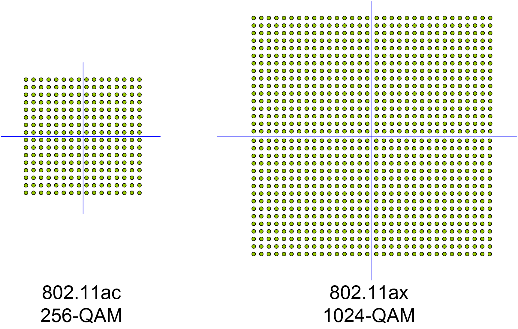
Quadrature Amplitude Modulation (QAM) is a modulation scheme that uses constellation diagrams for modulation.
802.11ac uses 256-QAM, which carries 8 bits of information per symbol. 802.11ax uses 1024-QAM, which carries 10 bits of information per symbol. Compared with 802.11ac, 802.11ax has improved the physical layer data rate by 25%.
Figure 1 802.11ac QAM and 802.11ax QAM
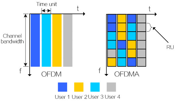
OFDMA
Orthogonal frequency-division multiplexing (OFDM) enables a single user to transmit data on all subcarriers at a given period of time. Based on OFDM, orthogonal frequency division multiple access (OFDMA) splits a channel into sub-channels, known as resource units (RUs), with specific subcarriers (tones), and assigns different RUs to different users for simultaneous transmission. This increases the data rate and reduces transmission latency. The technology is particularly applicable to devices transmitting a large number of short frames or devices with low data rate requirements, such as IoT devices.
Figure 2 OFDM and OFDMA working modes
In OFDMA, a signal is transmitted over several subcarriers, which determine the bandwidth that can be used by a user.
Subcarriers include the following types:
· Data subcarrier—Carries data.
· Pilot subcarrier—Carries phase and parameter tracking information.
· Unused subcarrier—Carries nothing to act as guard bands and isolate groups of subcarriers.
Each RU contains a minimum of 26 subcarriers and contains both data subcarriers and pilot subcarriers. For example, a 24-tone RU contains 24 data subcarriers and 2 pilot subcarriers and a 52-tone RU contains 48 data subcarriers and 4 pilot subcarriers.
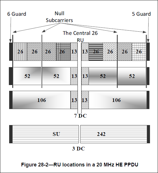
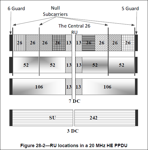
As shown in Figure 3, a 20 MHz bandwidth is formed by nine 26-tone RUs, among which –69, –3 to +3, and +69 subcarriers are null subcarriers. The first six and the last five subcarriers (a total of 11 subcarriers) act as the guide bands.
Figure 3 RU locations in a 20 MHz HE PPDU
Both downlink and uplink support RUs that contain 26, 52, 106, 242, 484, 996, or 2 × 996 tones.
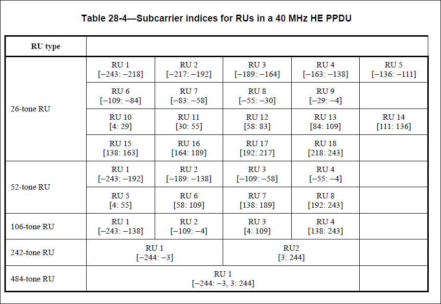
Table 2 and Table 3 show the distribution of RUs for 20 MHz and 40 MHz bands, respectively. As shown in the tables, RU tone mappings are inconsistent for bands of different widths, and multiple bandwidth allocations might cause signal overlapping. To avoid the overlapping issue when multiple bandwidth allocations exist, some 26-tone RUs are restricted to be used in 40, 80, 80+80, or 160 MHz OFDMA operation. For example, RU 5 and RU 14 are not available in the 40 MHz bandwidth formed by 26-tone RUs.
Table 2 Subcarrier indices for RUs in a 20 MHz HE PPDU
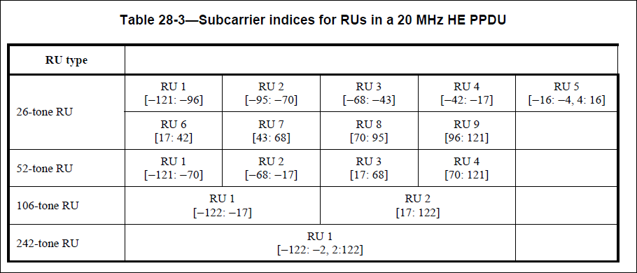
Table 3 Subcarrier indices for RUs in a 40 MHz HE PPDU
Increased data subcarriers
802.11ax increases the number of data subcarriers from 52 to 234, which extends OFDMA symbols by three times but increases usable subcarrier usage.
Table 4 and Table 5 show data rates of 802.11ac and 802.11ax for the 20 MHz bandwidth, respectively.
Table 4 802.11ac data rates for the 20 MHz bandwidth
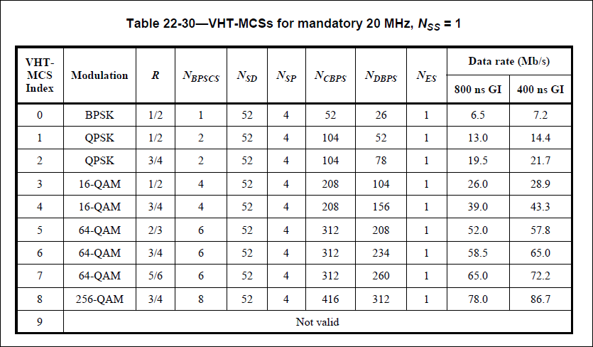
Table 5 802.11ax data rates for the 20 MHz bandwidth
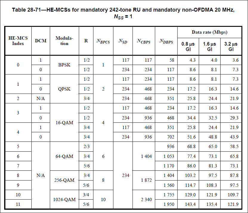
Table 6 Item description
|
Item |
Description |
|
R |
Coding rate. |
|
NBPCS |
Number of coded bits per subcarrier. |
|
NSD |
Number of data subcarriers. |
|
NSP |
Number of pilot carriers. |
|
NCBPS |
Number of carried bits per symbol. The number is calculated by using the following formula: NCBPS=NBPSCS × NSD × NSS |
|
NSS |
Number of spatial streams. |
|
NDBPS |
Number of data bits per symbol. The number is calculated by using the following formula: NDBPS=NCBPS × R. |
|
NES |
Number of BCC encoders. |
|
GI |
Guarding interval. |
For example, if the MCS index is 8, MCS parameters for 802.11ac and 802.11ax are shown in Table 7.
Table 7 Comparison of 802.11ac and 802.11ax (MCS index = 8)
|
Item |
Modulation |
R |
NBPCS |
NSD |
NCBPS |
NDBPS |
GI (ns) |
Data Rate (Mbps) |
|
802.11ac |
256-QAM |
3/4 |
8 |
52 |
416 |
312 |
800 |
78 |
|
802.11ax |
256-QAM |
3/4 |
8 |
234 |
1872 |
1404 |
800 |
103.2 |
As shown in Table 7, the 802.11ax data rate is improved from the following aspects:
· Increased subcarrier usage—The 802.11ac and 802.11ax subcarrier usages for data transmission are 0.81 (52/64) and 0.91 (234/256), respectively. The usage is calculated by dividing NSD by the number of total subcarriers.
Figure 4 RU locations in a 20 MHz high efficiency (HE) PPDU
· Increased data transmission efficiency—When the GI is 800 ns, the time required to transmit an 802.11ac symbol and an 802.11ax symbol are 4.0 (3.2+0.8) us and 13.6 (12.8+0.8) us, respectively. The proportions of the time used for transmitting 802.11ac data and 802.11ax data are 0.8 (3.2/4.0) and 0.94 (12.8/13.6), respectively.
Downlink OFDMA
Figure 5 and Figure 6 describe downlink non-OFDMA and OFDMA, respectively. As shown in the figures, with the same bandwidth, OFDMA can send data to three users at one Transmission Opportunity (TXOP) while non-OFDMA requires three TXOPs.
Figure 5 Downlink non-OFDMA transmission

Figure 6 Downlink OFDMA transmission

Uplink OFDMA
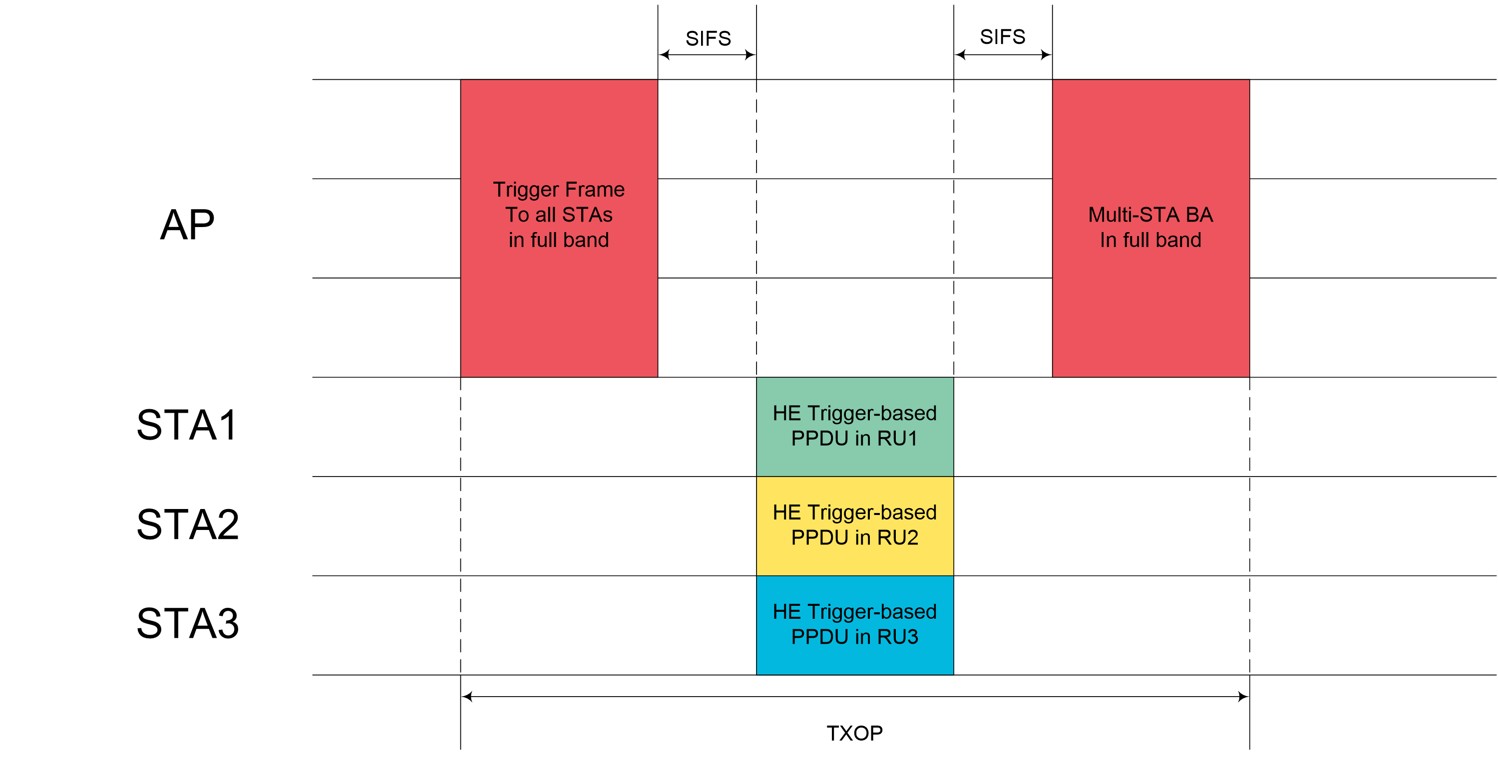
As shown in Figure 7 and Figure 8, uplink multi-user (MU) OFDMA operates as follows:
1. The AP sends a trigger frame to initiate an uplink MU exchange process.
2. Upon receiving the trigger frame, the clients wait for a SIFS and then send HE trigger-based PPDUs by using the method specified in the trigger frame.
3. Upon receiving the PPDUs, the AP waits for a SIFS and then sends a Block ACK (BA) frame to each client or sends a multi-STA BA frame to all clients (channel busy/idle state not considered).
This mechanism greatly reduces transmission latency caused by channel contention when processing concurrent multi-user traffic.
Figure 7 Uplink OFDMA with separate BAs
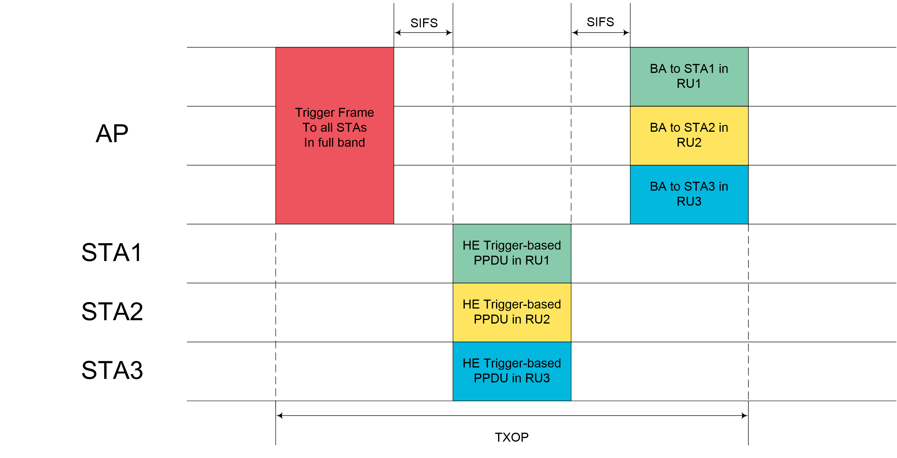
Figure 8 Uplink OFDMA with a multi-STA BA
MU-MIMO
Multi-user multiple-input multiple-output (MU-MIMO) splits bandwidth into individual streams to enable simultaneous receiving and transmission of data for multiple users. 802.11ac supports only downlink MU-MIMO with a maximum of 4 streams, and 802.11ax supports both uplink and downlink MU-MIMO with a maximum of 8 streams. This greatly improves data transmission efficiency.
Downlink MU-MIMO
Compared with 802.11ac, 802.11ax has improved the maximum number of supported users from four to eight and allows concurrent use of OFDMA and MU-MIMO. This greatly improves multi-user concurrency performance.
802.11ax can use the trigger mechanism of OFDMA to collect the compressed beamforming feedback (CBF) of multiple clients' channels at one TXOP, as shown in Figure 9. The following data exchange procedure is similar for 802.11ax and 802.11ac.
Figure 9 CBF collection of multiple users through OFDMA

Uplink MU-MIMO
In uplink MU-MIMO, clients first collect the CBF of the associated AP and then send a trigger frame to initiate an uplink MU-MIMO process. The following procedure is similar to uplink MU OFDMA.
Spatial reuse
Overlapping Basic Service Sets (OBSS)_Preamble Detection (PD)-based spatial reuse uses BSS coloring to identify intra-BSS packets and dynamically adjust transmit power to avoid co-channel interference.
BSS coloring
802.11ax assigns a non-unique ID (in the range of 1 to 63), called a BSS color, per BSS to help identify whether a packet is from the same BSS as the client.
After receiving an 802.11ax packet, a client first examines the color carried in the HE-SIG-A field of the packet header. If the color is the same as the color of the associated AP's BSS, the client determines that the packet is an intra-BSS packet. If the color is different from the color of the associated AP's BSS, the client determines that the packet is an inter-BSS packet. The client processes only intra-BSS packets and ignores inter-BSS packets.
Transmission power control
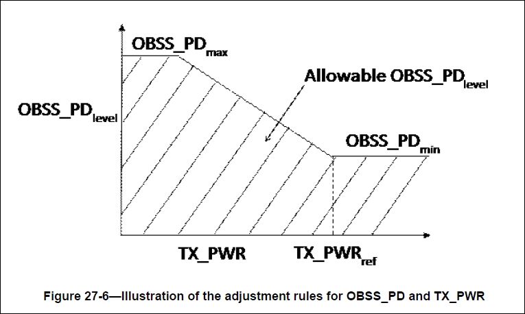
OBSS_PD-based spatial reuse uses OBSS_PD levels to adjust client transmit power. Available OBSS_PD levels are in the range of –82 dBm to –62 dBm.
Upon receiving an inter-BSS packet, a client compares the RSSI of the packet with the maximum OBSS_PD level (–62 dBm).
· If the RSSI is equal to or higher than the level, the client determines that inter-BSS interference is too strong and spatial reuse cannot be performed.
· If the RSSI is smaller than the level, the client selects an OBSS_PD level and adjusts its transmit power to a value smaller than the transmit power calculated by using the OBSS_PD level. The minimum transmit power (TX_PWRref in Figure 10) is 21 dBm.
In spatial reuse, each client maintains an inter-BSS NAV and an intra-BSS NAV, which are updated upon the receiving of inter-BSS packets and intra-BSS packets, respectively. Clients determine whether a channel is idle based on the intra-BSS NAV. The inter-BSS NAV is reserved for future use.
Figure 10 Adjustment rules for the OBSS_PD level and client transmit power
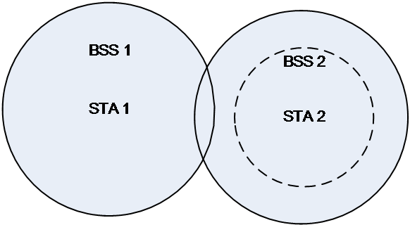
As shown in Figure 11, for example, BSS 1 and BSS 2 overlap with each other. BSS coloring enables client 2 to ignore packets from BSS 1 and transmission adjustment automatically reduces the transmit power of client 2 to reduce its wireless coverage (circled with a dotted line). This reduces co-channel interference and achieves spatial reuse without affecting communication in BSS 2.
Figure 11 Transmit power adjustment
TWT
Target Wake Time (TWT) allows APs to schedule the power saving period and wakeup of clients, reducing channel contention and power consumption by freeing clients from listening to beacons in sleep mode.
