| Title | Size | Downloads |
|---|---|---|
| Hardening H3C Comware 7 Switches-6W100-book.pdf | 576.29 KB |
- Table of Contents
- Related Documents
-
|
|
|
Hardening H3C Comware 7 Switches |
|
|
|
|
|
|
Copyright © 2019 New H3C Technologies Co., Ltd. All rights reserved.
No part of this manual may be reproduced or transmitted in any form or by any means without prior written consent of New H3C Technologies Co., Ltd.
Except for the trademarks of New H3C Technologies Co., Ltd., any trademarks that may be mentioned in this document are the property of their respective owners.
The information in this document is subject to change without notice.
Contents
Threats to the management and control planes
3 Hardening the management plane
Configuring ONU user authentication in EPON
User management and access control
Using RBAC to control user access permissions
Using AAA to secure user access and user management
Using command authorization to secure command access
Changing the password of the default user for SmartMC members
Disabling password recovery capability·
Configuring memory alarm thresholds
Suppressing ARP mobility events
Securing spanning tree networks
Securing LLDP neighbors on an interface
Enabling dynamic ARP entry check
Preventing ARP spoofing attacks
Limiting the number of Web authentication users
DHCP starvation attack protection
DHCP relay entry management on the DHCP relay agent
DHCP proxy on the DHCP relay agent
IPv6 address binding conversion for IP source guard
Disabling the TCP Timestamps option encapsulation
Hardening IGMP snooping and MLD snooping
Control plane packet rate limiting and packet-drop logging
Packet-drop logging for control plane protocols
WLAN access and management (Applicable only to devices with access controller functionality)
Enabling CAPWAP tunnel encryption
Configuring WLAN client access control
Configuring WLAN authentication to secure user access
Authenticating high availability protocol packets
Securing VRRP packet authentication
BFD control packet authentication
Configuring the NTP access right
Configuring user isolation (Applicable only to devices with access controller functionality)
Remotely configuring UNI isolation on an EPON ONU
Suppressing storms and controlling storms
Configuring storm suppression and storm control
Dropping unknown multicast data packets
MAC address security management
Configuring blackhole MAC address entries·
Disabling MAC address learning
Controlling and monitoring MAC address learning
Assigning MAC learning priority to interfaces
Enabling MAC move notifications and suppression
Securing EPON data transmission
Packet filtering & Traffic filtering
Configuring IP source guard (Applicable only to devices with access controller functionality)
Configuring the voice VLAN security mode
DoS attack detection and defense
1 About this document
This document helps you improve the overall network security by hardening the Comware 7 switches.
Audience
This document is intended for:
· Network planners.
· Field technical support and servicing engineers.
· Network administrators.
Port numbering in examples
The port numbers in this document are for illustration only and might be unavailable on your device.
Prerequisites
This document is not restricted to specific software or hardware versions.
The configuration examples were created and verified in a lab environment, and all the devices were started with the factory default configuration. When you are working on a live network, make sure you understand the potential impact of every command on your network.
This document provides only generic technical information, some of which might not apply to your devices.
|
|
NOTE: All settings in the examples throughout this document are for illustration only. When you use the commands in the examples to harden your device, change the settings as appropriate to your network security requirements. |
2 Overview
The functions of Comware 7 switches are categorized into the management plane, control plane, and data plane. This document helps you improve the overall network security by hardening the security of these three planes.
Security threats
Threats to the management and control planes
The management plane manages administrative access to the device through applications and protocols such as Telnet, SSH, Web, and SNMP. Protecting the management plane against unauthorized access and attacks is essential to the security of the entire network. If the management plane is breached,
The control plane contains applications and protocols that are running between devices to maintain the functionality of the network architecture and facilitate the functions of the data plane. For example, routers run routing protocols such as OSPF or BGP between them to learn about routes and switches run protocols such as spanning tree protocols to learn about various paths.
Security threats to the management and control planes of a network device come from various sources, including malicious users, compromised remote network devices, and an inappropriate security policy.
The following are common security threats to the management and control planes:
· Unauthorized access.
An attacker can gain access to the device by forging the identity of the administrator or launching management session replay attacks or man-in-the-middle attacks.
To protect administrative sessions to the device, configure strong identity authentication, establish secure access channels, and perform anti-replay and message integrity check. In addition, enable operations and security event logging to record and audit administrative behavior of users.
· Weak password.
A weak password is easy to crack. As a best practice, configure a password policy to require strong passwords for administrative access.
· Sensitive information leaking
Important or confidential information might be eavesdropped on the transmission path. Stored contents might be leaked when the storage device is transferred or replaced.
To guarantee the confidentiality of sensitive information:
¡ Avoid establishing insecure administrative sessions to the device by using protocols such as Telnet, FTP, TFTP, or HTTP. Instead, establish secure administrative sessions by using protocols such as SSH, IPsec, SFTP, and HTTPS.
¡ Encrypt the startup configuration file.
¡ Format the removed storage devices before you dispose of them, making sure the removed data cannot be restored.
· Message tampering and forging.
An attacker might tamper with or replay messages on the transmission path to inject malicious data or tamper with data on a network device. For example, attackers can tamper with routing protocol packets to influent the path of packets.
To protect the control plane, configure security services including integrity check and anti-replay.
· Distributed denial of service (DDoS) attacks.
In a DDoS attack, the attacker sends a large number of packets to exhaust the device resources, including CPU, memory, sessions, and bandwidth. Busy with handling illegitimate packets, the victim network device will be unable to provide forwarding services to users.
To protect a network device against DDoS attacks:
¡ Use a whitelist to identify trusted remote devices.
¡ Use a blacklist to block traffic from suspicious remote devices.
¡ Limit the rate at which traffic is sent to the control plane.
· Misconfiguration.
Misconfiguration might result in incorrect access control, permission assignment, or authorization.
To avoid security risks introduced because of misconfiguration:
¡ Verify the configuration before deploying it.
¡ Constantly audit the device behavior after the configuration is deployed, for example, by reviewing the operation log or system log.
Threats to the data plane
The data plane forwards data from source to destination. If the data plane was attacked, the forwarding performance would downgrade significantly and in the worst case, malicious packets would spread in the network.
Common security threats to the data plane include:
· Malformed packet attacks.
Attackers can exploit the packet processing vulnerabilities in the data plane to attack the device, causing the device to malfunction or crash.
To detect and prevent potential malformed packet attacks, enable attack detection and prevention.
· DDoS attacks.
DDoS attack occurs when an attacker sends a large number of packets to exhaust the device resources, including CPU, memory, connections, and bandwidth.
To protect the device against such attacks, configure resource usage thresholds to ensure that the device always has resources for normal services. In addition, authenticate users, identify illegitimate traffic, and limit the traffic of unrecognizable users.
· Identity spoofing.
Identity spoofing is part of many attacks. Identifying spoofed identities can effectively prevent attacks. However, the openness of the network makes this job very difficult, especially on the data plane.
To identify spoofed identifies on the data plane, you can use security features such as IP source guard, SYN Cookie, ARP attack protection, and ND attack defense.
· Message tampering and forging.
Message integrity is critical to network functionality. False data might cause network failure or even network paralysis.
As a best practice, use security protocols such as IPsec and MACsec to protect data flows in the network. Securing mechanisms include integrity check, confidentiality offset, and identity authentication.
Security architecture
Figure 2-1 shows the security architecture of Comware.
Figure 2-1 Comware security architecture
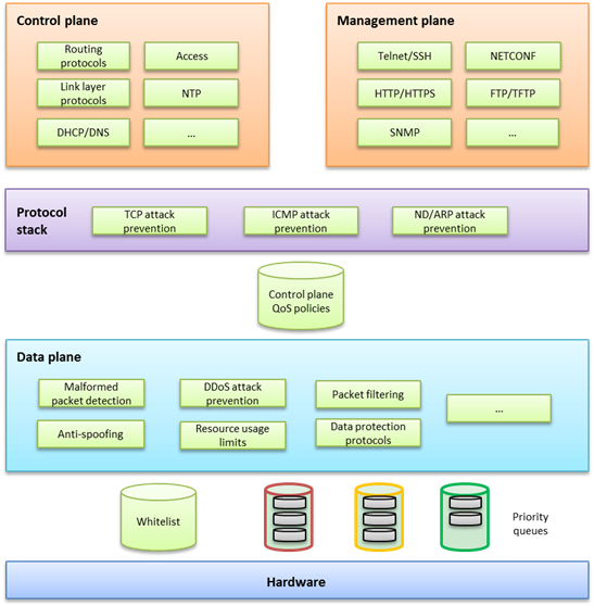
This security architecture offers multilayer protection to ensure overall security.
If a device offers hardware forwarding, its hardware layer uses whitelist and priority queuing mechanisms to protect the control and management planes from DoS or DDoS attacks. These mechanisms handle packets destined for the local device as follows before delivering them from the hardware layer to the CPU:
¡ Whitelist—If a source is trustworthy and a session has been established to it, the source is added to the whitelist. The hardware layer preferentially delivers all its packets to the CPU.
¡ Priority queues—If a packet is not from a source in the whitelist, the hardware layer enques the packet in a priority queue depending on its protocol. Packets in any priority queues have lower priority than packets from a whitelist source.
· On the forwarding plane, Comware provides a variety of security features, including:
¡ Malformed packet detection.
¡ Packet filtering.
¡ Anti-spoofing, for example uRPF and IP source guard.
¡ DDoS attack defense.
¡ Resource usage limits, including connection limit and ARP/ND table entry limit.
¡ Data protection protocols, such as IPsec and MACsec.
· On the control and management planes, Comware provides security features including:
¡ QoS policy configurable to limit or filter traffic delivered to the control or management plane. For example, you can limit the rate of traffic sent to the control plane. You can also configure application security features to protect the control plane against attacks such as TCP attacks, ICMP/ICMPv6 attacks, ARP attacks, and ND attacks.
¡ Security protocols or options specific to service modules for enhanced service protection.
Basic hardening principles
Enforcing security features aligned with your network environment, security needs, and protected objects is critical to the effective protection of your network. Hardening a network device with as many security features as you have would increase costs, add configuration complexities, and impact device performance without making it more secure.
To effectively protect a network device:
1. Identify major threats and risks that the network device is facing and sort them by their impact on your business.
2. Select and phase in security features to protect the network device against the identified threats and risks by their significance.
3. Constantly evaluate the protection effect after a security feature or a set of security features is introduced.
4. Depending on the evaluation conclusion, change or phase in security features until the security risks to the business are mitigate to an acceptable or minimum level.
3 Hardening the management plane
Device access control
Securing console/USB access
Security threats
The device provides the following physical interfaces: console and USB ports. By default, console login and USB login are both enabled and do not require authentication. The user role is network-admin for a console or USB user. Any user who can connect a terminal to a console or USB port can log in to the device and manage the device.
Hardening recommendations
Configure one of the following authentication modes in user line view or line class view immediately after you log in to the device for the first time:
· Password authentication—Requires a password for authentication. A user must provide the correct password at login. This authentication mode is not supported in FIPS mode.
· Scheme authentication—Uses the AAA module to provide local or remote login authentication. A user must provide the correct username and password at login.
After configuring password or scheme authentication, keep the password or username and password securely.
Restrictions and guidelines
A console or USB login configuration change takes effect only on users who log in after the change is made. It does not affect users who are already online when the change is made.
In FIPS mode, the device supports only scheme authentication. You cannot disable authentication or configure password authentication.
Examples
· Secure console login:
# Configure password authentication in console line view.
<Sysname> system-view
[Sysname] line console 0
[Sysname-line-console0] authentication-mode password
# Specify a password.
[Sysname-line-console0] set authentication password simple Plat&0631!
Alternatively:
# Configure scheme authentication in console line view.
<Sysname> system-view
[Sysname] line console 0
[Sysname-line-console0] authentication-mode scheme
[Sysname-line-console0] quit
# Configure authentication methods for login users in ISP domain view.
To use local authentication, configure a local user and set the relevant attributes. To use remote authentication, configure a RADIUS, HWTACACS, or LDAP scheme. For more information, see AAA in Security Configuration Guide.
· Secure console login:
# Configure password authentication in AUX line view.
<Sysname> system-view
[Sysname] line aux 0
[Sysname-line-aux0] authentication-mode password
[Sysname-line-aux0] set authentication password simple Plat&0631!
Alternatively:
# Configure scheme authentication in AUX line view.
<Sysname> system-view
[Sysname] line aux 0
[Sysname-line-aux0] authentication-mode scheme
# Configure authentication methods for login users in ISP domain view.
To use local authentication, configure a local user and set the relevant attributes. To use remote authentication, configure a RADIUS, HWTACACS, or LDAP scheme. For more information, see AAA in Security Configuration Guide.
· Secure USB login:
# Configure password authentication in USB line view.
<Sysname> system-view
[Sysname] line usb 0
[Sysname-line-usb0] authentication-mode password
# Specify a password.
[Sysname-line-usb0] set authentication password simple Plat&0631!
# Configure scheme authentication in USB line view.
<Sysname> system-view
[Sysname] line usb 0
[Sysname-line-usb0] authentication-mode scheme
# Configure authentication methods for login users in ISP domain view.
To use local authentication, configure a local user and set the relevant attributes. To use remote authentication, configure a RADIUS, HWTACACS, or LDAP scheme. For more information, see AAA in Security Configuration Guide.
Securing Stelnet access
Security threats
Stelnet users might face the following security threats:
· An attacker might scan for and obtain the SSH service port number, and then try to Stelnet to the device again and again to log in to the device.
· The device supports a limited number of concurrent SSH users. An attacker might use spoofed IP addresses and valid usernames and passwords to Stelnet to the device, making legal users unable to Stelnet to the device.
Hardening recommendations
To protect the device against the security threats, you can use the following security policies:
· Password authentication
The SSH server authenticates a client by using the AAA mechanism. The password authentication process is as follows:
a. The client sends the server an authentication request that includes the encrypted username and password.
b. The server decrypts the request, verifies the username and password locally or through remote AAA authentication, and informs the client of the authentication result.
· Publickey authentication
The SSH server authenticates a client by verifying the digital signature of the client. The publickey authentication process is as follows:
a. The client sends the server a publickey authentication request that includes the username, public key, and public key algorithm name.
If the digital certificate of the client is required in authentication, the client also encapsulates the digital certificate in the authentication request. The digital certificate carries the public key information of the client.
b. The server verifies the client's public key.
- If the public key is invalid, the server informs the client of the authentication failure.
- If the public key is valid, the server requests the digital signature of the client. After receiving the signature, the server uses the public key to verify the signature and informs the client of the authentication result.
· Password-publickey authentication
The SSH server requires SSH2 clients to pass both password authentication and publickey authentication. An SSH1 client only needs to pass either authentication.
· Keyboard-interactive authentication
In keyboard-interactive authentication, the remote authentication server and user exchange information for authentication as follows:
a. The remote authentication server sends a prompt to the SSH server in an authentication response. The prompt indicates the information required to be provided by the user.
b. The SSH server transparently transmits the prompt to the client.
c. The user enters the required information as prompted.
This process repeats multiple times if the remote authentication server requires more interactive information. The remote authentication server returns an authentication success message after the user provides all required interactive information.
If the remote authentication server does not require interactive information, the keyboard-interactive authentication process is the same as the password authentication.
· Disabling the Stelnet service
Disable the Stelnet service when it is not required. The SSH service port number is easy to be found by a scanning attacker.
· Changing the SSH service port number to a non-well-known port number
By default, the SSH service port number is well-known port number 22, which is an easy target. Changing the SSH service port number reduces the risk to be attacked.
· Configuring SSH access control
Apply an ACL to control access to the SSH server, so only IPv4 SSH clients permitted by the ACL can access the SSH server.
· Limiting the number of concurrent SSH users
If the maximum number of concurrent SSH users is reached, the SSH server rejects additional connection requests.
Restrictions and guidelines
A Stelnet login configuration change takes effect only on users who log in after the change is made. It does not affect users who are already online when the change is made.
Examples
· # Configure password authentication for an SSH user.
<Sysname> system-view
[Sysname] ssh user client001 service-type stelnet authentication-type password
# For local authentication, configure a local user on the SSH server. For remote authentication, configure an SSH user on a remote authentication server, for example, a RADIUS server. For more information, see AAA in Security Configuration Guide.
· # Configure publickey authentication for an SSH user.
<Sysname> system-view
[Sysname] ssh user client002 service-type stelnet authentication-type publickey assign publickey clientkey
# Create a local user that uses the same username and assign a working directory and user roles to the user. For more information, see AAA in Security Configuration Guide.
· # Disable the Stelnet service.
<Sysname> system-view
[Sysname] undo ssh server enable
· # Change the SSH service port number to a non-well-known port number.
<Sysname> system-view
[Sysname] ssh server port 1025
· # Apply an ACL to permit only SSH access from 1.1.1.1.
<Sysname> system-view
[Sysname] acl basic 2001
[Sysname-acl-ipv4-basic-2001] rule permit source 1.1.1.1 0
[Sysname-acl-ipv4-basic-2001] quit
[Sysname] ssh server acl 2001
· # Set the maximum number of concurrent SSH users.
<Sysname> system-view
[Sysname] aaa session-limit ssh 16
Securing RESTful access
Hardening recommendations
As a best practice, use RESTful access over HTTPs, which is more secure than RESTful access over HTTP.
Examples
# Enable the RESTful access over HTTPS service.
<Sysname> system-view
[Sysname] restful https enable
Securing SNMP access
Security threats
The device might face the following threats when it acts as an SNMP agent:
· An attacker might steal SNMPv1 or SNMPv2c community names and use them to access the device.
· An attacker might eavesdrop on and tamper with SNMP packets.
· Legal users of NMSs might perform tasks mistakenly, causing the device unable to operate correctly.
Hardening recommendations
To protect the device against the security threats, you can use the following security policies:
· Disabling the SNMP agent when it is not required. By default, the SNMP agent is disabled.
· Using SNMPv3, which is more secure than SNMPv1 and SNMPv2c. SNMPv3 uses a user-based security model to secure SNMP communication. You can configure authentication and privacy mechanisms to authenticate and encrypt SNMP packets for integrity, authenticity, and confidentiality.
· Using the following modes to control access to MIB objects:
¡ View-based Access Control Model—VACM mode controls access to MIB objects by assigning MIB views to SNMP communities or users.
¡ Role based access control—RBAC mode controls access to MIB objects by assigning user roles to SNMP communities or users.
RBAC mode controls access on a per MIB object basis, and VACM mode controls access on a MIB view basis. As a best practice to enhance MIB security, use the RBAC mode.
· Applying an ACL to permit only legal NMSs to access the SNMP agent.
· Encapsulating security parameters in notifications to allow only NMSs that satisfy the requirements can receive the notifications.
Restrictions and guidelines
For an NMS to connect to the device, make sure they use the same SNMP version and community name (or username and password).
Examples
· Disable the SNMP agent:
# Disable the SNMP agent.
<Sysname> system-view
[Sysname] undo snmp-agent
· Enable SNMPv3 on the device and use a user role to control access to MIB nodes:
# Enable SNMPv3.
<Sysname> system-view
[Sysname] snmp-agent sys-info version v3
# Configure a user role that has only the following rights:
¡ Read right to objects of node snmpMIB (OID=1.3.6.1.6.3.1) and node system (OID=1.3.6.1.2.1.1).
¡ Read and write rights to objects of node interfaces (OID=1.3.6.1.2.1.2). These rights enable the device to report interface status changes to the NMS.
[Sysname] role name test
[Sysname-role-test] rule 1 permit read oid 1.3.6.1.6.3.1
[Sysname-role-test] rule 2 permit read oid 1.3.6.1.2.1.1
[Sysname-role-test] rule 3 permit read write oid 1.3.6.1.2.1.2
[Sysname-role-test] quit
# Create an SNMPv3 user, assign the configured user role to the user, and specify the authentication and encryption algorithms and passwords.
[Sysname] snmp-agent usm-user v3 RBACtest user-role test simple authentication-mode sha 123456TESTauth&! privacy-mode aes128 123456TESTencr&!
· Apply an ACL to control access to the SNMP agent.
# Create an SNMPv3 group, add a user to the group, and specify the authentication and encryption algorithms and passwords. Configure an ACL to permit only SNMPv3 access from 1.1.1.1.
<Sysname> system-view
[Sysname] acl basic 2000
[Sysname-acl-ipv4-basic-2000] rule permit source 1.1.1.1 0
[Sysname-acl-ipv4-basic-2000] rule deny source any
[Sysname-acl-ipv4-basic-2000] quit
[Sysname] snmp-agent group v3 testGroup authentication
[Sysname] snmp-agent usm-user v3 testUser testGroup simple authentication-mode sha 123456TESTauth&! privacy-mode aes128 123456TESTencr&! acl 2000
· Enable SNMP notifications.
# Enable SNMP notifications, specify the SNMP notification target host and username, and select the authentication with privacy security model.
<Sysname> system-view
[Sysname] snmp-agent trap enable
[Sysname] snmp-agent target-host trap address udp-domain 1.1.1.2 params securityname testUser v3 privacy
Securing Web access
Hardening recommendations
As a best practice, use HTTPs for Web access, which is more secure than HTTP. HTTPS uses SSL to ensure the integrity and security of data exchanged between the client and the server.
By default, the device uses a self-signed certificate and the default SSL settings. To secure Web access, you can configure an SSL server policy for HTTPS.
You can also define a certificate-based access control policy to allow only legal clients to access the Web interface.
Examples
# Configure an SSL server policy. (Details not shown. For more information, see SSL configuration in Security Configuration Guide.)
# Configure a certificate-based access control policy and add rules. (Details not shown. For more information, see PKI configuration in Security Configuration Guide.)
# Apply the SSL server policy to the HTTPS service.
<Sysname> system-view
[Sysname] ip https ssl-server-policy myssl
# Apply the certificate-based access control policy to the HTTPS service so only HTTPS clients that have obtained a certificate from the CA server can use the HTTPS service.
[Sysname] ip https certificate access-control-policy myacp
# Enable the HTTPS service.
[Sysname] ip https enable
# Configure authentication methods for login users in ISP domain view.
To use local authentication, configure a local user and set the relevant attributes. To use remote authentication, configure a RADIUS, HWTACACS, or LDAP scheme. For more information, see AAA in Security Configuration Guide.
Securing file access
Security threats
Commonly used file transfer protocols FTP and TFTP transfer files in plain text. Attackers can capture the transferred packets easily.
Hardening recommendations
To protect the device against the security threat, use Secure FTP (SFTP). Based on SSH2, SFTP uses SSH connections to provide secure file transfer. The device can act as an SFTP server, allowing a remote user to log in to the SFTP server for secure file management and transfer. The device can also act as an SFTP client, enabling a user to log in from the device to a remote device for secure file transfer.
To secure file transfer, SFTP uses the following security policies:
· Password authentication
The SSH server authenticates a client by using the AAA mechanism. The password authentication process is as follows:
a. The client sends the server an authentication request that includes the encrypted username and password.
b. The server decrypts the request, verifies the username and password locally or through remote AAA authentication, and informs the client of the authentication result.
· Publickey authentication
The SSH server authenticates a client by verifying the digital signature of the client. The publickey authentication process is as follows:
a. The client sends the server a publickey authentication request that includes the username, public key, and public key algorithm name.
If the digital certificate of the client is required in authentication, the client also encapsulates the digital certificate in the authentication request. The digital certificate carries the public key information of the client.
b. The server verifies the client's public key.
- If the public key is invalid, the server informs the client of the authentication failure.
- If the public key is valid, the server requests the digital signature of the client. After receiving the signature, the server uses the public key to verify the signature and informs the client of the authentication result.
· Password-publickey authentication
The SSH server requires SSH2 clients to pass both password authentication and publickey authentication. An SSH1 client only needs to pass either authentication.
· Keyboard-interactive authentication
In keyboard-interactive authentication, the remote authentication server and user exchange information for authentication as follows:
a. The remote authentication server sends a prompt to the SSH server in an authentication response. The prompt indicates the information required to be provided by the user.
b. The SSH server transparently transmits the prompt to the client.
c. The user enters the required information as prompted.
This process repeats multiple times if the remote authentication server requires more interactive information. The remote authentication server returns an authentication success message after the user provides all required interactive information.
If the remote authentication server does not require interactive information, the keyboard-interactive authentication process is the same as the password authentication.
· Changing the SSH service port number to a non-well-known port number
By default, the SSH service port number is well-known port number 22, which is an easy target. Changing the SSH service port number reduces the risk to be attacked.
· Configuring SSH access control
Apply an ACL to control access to the SSH server, so only IPv4 SSH clients permitted by the ACL can access the SSH server.
· Limiting the number of concurrent SSH users
If the maximum number of concurrent SSH users is reached, the SSH server rejects additional connection requests.
Examples
· # Enable the SFTP server, and configure an SSH user that uses password authentication.
<Sysname> system-view
[Sysname] sftp server enable
[Sysname] ssh user client001 service-type sftp authentication-type password
# For local authentication, configure a local user on the SSH server. For remote authentication, configure an SSH user on a remote authentication server, for example, a RADIUS server. For more information, see AAA in Security Configuration Guide.
· # Enable the SFTP server, and configure an SSH user that uses publickey authentication.
<Sysname> system-view
[Sysname] sftp server enable
[Sysname] ssh user client002 service-type sftp authentication-type publickey assign publickey clientkey
# Create a local user that uses the same username and assign a working directory and user roles to the user. For more information, see AAA in Security Configuration Guide.
· # Change the SSH service port number to a non-well-known port number.
<Sysname> system-view
[Sysname] ssh server port 1025
· # Apply an ACL to permit only SSH access from 1.1.1.1.
<Sysname> system-view
[Sysname] acl basic 2001
[Sysname-acl-ipv4-basic-2001] rule permit source 1.1.1.1 0
[Sysname-acl-ipv4-basic-2001] quit
[Sysname] ssh server acl 2001
· # Set the maximum number of concurrent SSH users.
<Sysname> system-view
[Sysname] aaa session-limit ssh 16
Configuring ONU user authentication in EPON
Security threats
By default, ONU authentication is disabled on an OLT port. An ONU user can directly access the EPON through an OLT port.
Hardening recommendations
To secure the EPON, as a best practice, enable ONU authentication on an OLT port. Then, users that access through the OLT port are authenticated by using the specified domain. The authentication domain defines the authentication scheme for ONU users. For more information about authentication domains, see Security Configuration Guide.
Restrictions and guidelines
The ONU authentication feature takes effect only when the automatic ONU binding feature is enabled.
Examples
# Enable ONU authentication for OLT 1/0/1, and specify the domain named test for ONU users on the OLT port.
<Sysname> system-view
[Sysname] interface Olt 1/0/1
[Sysname-Olt1/0/1] onu authentication-domain test
[Sysname-Olt1/0/1] quit
# Enable automatic ONU binding for the specified slot.
[Sysname] ftth
[Sysname-ftth] onu bind auto slot 1
[Sysname-ftth] quit
FC port security
Typically, any device (a node or switch) in a SAN can log in to an FCF switch. The port security feature prevents unauthorized access to switch interfaces.
After you configure port security for a VSAN, the switch performs authorization checks on each device that attempts to log in based on the port security database.
· If the device passes the authorization checks, it is allowed to log in.
· If the device fails the authorization checks, it is denied.
The port security feature allows you to control access of the following devices:
· An N_Port specified by its pWWN.
· An NP_Port specified by its pWWN.
· A node specified by its nWWN (represents all N_Ports on the node).
· An NPV switch specified by its nWWN (represents all NP_Ports on the NPV switch).
· An FCF switch specified by its sWWN.
For more information about FC port security, see port security in FC and FCoE Configuration Guide.
User management and access control
Using RBAC to control user access permissions
Role-based access control (RBAC) controls access permissions of users based on user roles, enabling granular control of access to the device.
With RBAC, you create user roles for different job functions (for example, different security purposes). Then, assign each user role the permission to access a set of features and system resources.
For more information about RBAC, see Fundamentals Configuration Guide.
Using AAA to secure user access and user management
Authentication, Authorization, and Accounting (AAA) provides a uniform framework for implementing network access management. This feature specifies the following security functions:
· Authentication—Identifies users and verifies their validity.
· Authorization—Grants different users different rights, and controls the users' access to resources and services. For example, you can permit office users to read and print files and prevent guests from accessing files on the device.
· Accounting—Records network usage details of users, including the service type, start time, and traffic. This function enables time-based and traffic-based charging and user behavior auditing.
AAA has various implementations, including RADIUS, HWTACACS, and LDAP. RADIUS is most often used.
HWTACACS and RADIUS have many features in common, such as using a client/server model, using shared keys for data encryption, and providing flexibility and scalability. However, HWTACACS has the following advantages compared with RADIUS:
· Uses TCP, which provides reliable network transmission.
· Encrypts the entire packet except for the HWTACACS header.
· Uses complicated protocol packets and separates authorization from authentication. Authentication and authorization can be deployed on different HWTACACS servers.
· Supports authorization of configuration commands. Access to commands depends on both the user's roles and authorization. A user can use only commands that are permitted by the user roles and authorized by the HWTACACS server.
Using command authorization to secure command access
Hardening recommendations
By default, commands available for a user depend only on the user's user roles. When the authentication mode is scheme, you can configure the command authorization feature to further control a user's access to commands.
When command authorization is enabled, a user can use only commands that are permitted by both the AAA scheme and user roles.
Examples
# Enable command authorization.
<Sysname> system-view
[Sysname] line vty 0 4
[Sysname-line-vty0-4] authentication-mode scheme
[Sysname-line-vty0-4] command authorization
# Configure command authorization methods in ISP domain view. The command authorization methods can be the same as or different from the user login authorization methods. For more information about the authorization methods, see AAA configuration in Security Configuration Guide.
Password control
Security threats
A user password on the device might pose security threats in the following situations:
· If the password is short and simple, and the number of login attempts is not limited, the password might be easily cracked through a dictionary attack.
· If the password has no aging time and is idle for a long period, it can be cracked through continuous attempts.
· If the password is the initial password, it will be cracked easily. Because an initial password might be a weak password created by a single rule.
Hardening recommendations
Password control allows you to implement the following features:
· Password length, composition, and complexity.
¡ Minimum password length.
¡ Password composition policy.
¡ Password complexity checking policy.
· Password updating and expiration.
¡ Password updating.
¡ Password expiration.
¡ Early notice on pending password expiration.
¡ Login with an expired password.
¡ Password history.
· User login control.
¡ First login control.
¡ Limit on number of login attempts
¡ Maximum account idle time.
For more information about local users, see AAA in Security Configuration Guide. For information about super passwords, see RBAC in Fundamentals Configuration Guide. For more information about password control, see Security Configuration Guide.
Changing the password of the default user for SmartMC members
Hardening recommendations
Smart Management Center (SmartMC) centrally manages and maintains dispersed network devices at network edges. In a SmartMC network, only one device acts as the commander and the remaining devices all act as members.
During SmartMC network establishment, the commander uses the default username and password to establish NETCONF sessions to members automatically added to the network. The default username and password are admin and admin. To enhance security, you can perform this task to change the password for the default user admin of the members after the commander adds the members to the network.
Restrictions and guidelines
This feature does not change the password of user admin for local member login. You must change the password for local login on each member separately.
Examples
# Change the password of the default user for members to Admin123&.
<Sysname> system-view
[Sysname] smartmc tc password Admin123&
Hardening in password setting
The device supports the following forms of passwords (or keys):
· Plaintext form—Users enter their passwords in plaintext form, and the device stores the passwords in encrypted form or hashed form.
· Encrypted form—Users enter their passwords in encrypted form, and the device stores the passwords in encrypted form.
· Hashed form—Users enter their passwords in encrypted form, and the device stores the passwords in hashed form.
To improve the system security and maintainability, follow these guidelines to harden passwords:
· Use long and complicated passwords instead of weak passwords.
· Use a unique password for each service to prevent collateral threats to other services caused by the cracking of a service password.
· For successful password setting, make sure passwords set in encrypted or hashed form can be decrypted by the device. Typically, passwords in encrypted or hashed form are used for tests or configuration recovery. Do not use passwords in these forms for normal services.
Device management
Disabling password recovery capability
Security threats
By default, password recovery capability is enabled. If you forget the console login password or fails console login authentication, you can press Ctrl+B while the master device or active MPU is starting up to access the BootWare menu and solve the issue. However, attackers can exploit this capability to access the device through the console port.
Hardening recommendations
Disable password recovery capability so console users must restore the factory-default configuration before they can configure new passwords. Restoring the factory-default configuration deletes the next-startup configuration files.
Examples
# Disable password recovery capability.
<Sysname> system-view
[Sysname] undo password-recovery enable
Disabling USB interfaces
Security threats
By default, all USB interfaces are enabled. A user can use USB interfaces to upload or download files. Important files might be illegally copied and USB disks might carry viruses.
Hardening recommendations
Enable USB interfaces only when necessary, and disable USB interfaces immediately after you finish using USB interfaces.
Restrictions and guidelines
If a USB disk is partitioned, you must use the umount command to unmount all USB partitions before you can disable USB interfaces.
Examples
# Disable USB interfaces.
<Sysname> system-view
[Sysname] usb disable
Configuring memory alarm thresholds
Security threats
When the device is running out of memory, features might not be able to install table entries or save important data, affecting correct system operation.
Hardening recommendations for devices that do not support early warning
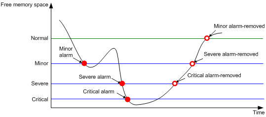
To ensure correct operation and improve memory efficiency, the device monitors the amount of free memory space in real time. If the amount of free memory space reaches the minor, severe, or critical alarm threshold, the system issues an alarm to affected service modules and processes.
As shown in Table 3-1 and Figure 3-1, the device supports the following free-memory thresholds:
· Normal state threshold.
· Minor alarm threshold.
· Severe alarm threshold.
· Critical alarm threshold.
Table 3-1 Memory alarm notifications and memory alarm-removed notifications
|
Notification |
Triggering condition |
Remarks |
|
Minor alarm notification |
The amount of free memory space decreases below the minor alarm threshold. |
After generating and sending a minor alarm notification, the system does not generate and send any additional minor alarm notifications until the minor alarm is removed. |
|
Severe alarm notification |
The amount of free memory space decreases below the severe alarm threshold. |
After generating and sending a severe alarm notification, the system does not generate and send any additional severe alarm notifications until the severe alarm is removed. |
|
Critical alarm notification |
The amount of free memory space decreases below the critical alarm threshold. |
After generating and sending a critical alarm notification, the system does not generate and send any additional critical alarm notifications until the critical alarm is removed. |
|
Critical alarm-removed notification |
The amount of free memory space increases above the severe alarm threshold. |
N/A |
|
Severe alarm-removed notification |
The amount of free memory space increases above the minor alarm threshold. |
N/A |
|
Minor alarm-removed notification |
The amount of free memory space increases above the normal state threshold. |
N/A |
Figure 3-1 Memory alarm notifications and alarm-removed notifications
Hardening recommendations for devices that support early warning
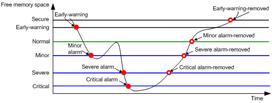
To ensure correct operation and improve memory efficiency, the device monitors the amount of free memory space in real time. If the amount of free memory space reaches the minor, severe, or critical alarm threshold, the system issues an alarm to affected service modules and processes.
The early warning feature warns you of an approaching insufficient-memory condition.
As shown in Table 3-2 and Figure 3-2, the device supports the following free-memory thresholds:
· Sufficient-memory threshold.
· Early-warning threshold.
· Normal state threshold.
· Minor alarm threshold.
· Severe alarm threshold.
· Critical alarm threshold.
Table 3-2 Memory alarm notifications and memory alarm-removed notifications
|
Notification |
Triggering condition |
Remarks |
|
Early-warning notification |
The amount of free memory space decreases below the early-warning threshold. |
After generating and sending an early-warning notification, the system does not generate and send any additional early-warning notifications until the early warning is removed. |
|
Minor alarm notification |
The amount of free memory space decreases below the minor alarm threshold. |
After generating and sending a minor alarm notification, the system does not generate and send any additional minor alarm notifications until the minor alarm is removed. |
|
Severe alarm notification |
The amount of free memory space decreases below the severe alarm threshold. |
After generating and sending a severe alarm notification, the system does not generate and send any additional severe alarm notifications until the severe alarm is removed. |
|
Critical alarm notification |
The amount of free memory space decreases below the critical alarm threshold. |
After generating and sending a critical alarm notification, the system does not generate and send any additional critical alarm notifications until the critical alarm is removed. |
|
Critical alarm-removed notification |
The amount of free memory space increases above the severe alarm threshold. |
N/A |
|
Severe alarm-removed notification |
The amount of free memory space increases above the minor alarm threshold. |
N/A |
|
Minor alarm-removed notification |
The amount of free memory space increases above the normal state threshold. |
N/A |
|
Early-warning-removed notification |
The amount of free memory space increases above the sufficient-memory threshold. |
N/A |
Figure 3-2 Memory alarm notifications and alarm-removed notifications
Restrictions and guidelines
If a memory alarm occurs, delete unused configuration items or disable some features to increase the free memory space. Because the memory space is insufficient, some configuration items might not be able to be deleted.
Examples
# Set the minor, severe, and critical free-memory alarm thresholds to 3000 MB, 2000 MB, and 1000 MB, respectively. Set the normal state threshold to 3500 MB.
<Sysname> system-view
[Sysname] memory-threshold minor 3000 severe 2000 critical 1000 normal 3500
Configuration encryption
Hardening recommendations
To protect the startup configuration file, use configuration encryption. This feature enables the device to encrypt a startup configuration file automatically when it saves the running configuration to the file. All devices running Comware 7 software use the same private key or public key to encrypt configuration files.
Any devices running Comware 7 software can decrypt the encrypted configuration files. To prevent an encrypted file from being decoded by unauthorized users, make sure the file is accessible only to authorized users.
Restrictions and guidelines
You cannot use the more command or display commands to view the contents of an encrypted configuration file. However, you can use the display saved-configuration command to display the contents of the encrypted next-startup configuration file or use the display diff command to compare an encrypted configuration file with other configurations.
Examples
# Enable the public-key method for configuration encryption.
<Sysname> system-view
[Sysname] configuration encrypt public-key
# Enable the private-key method for configuration encryption.
<Sysname> system-view
[Sysname] configuration encrypt private-key
Security logs
Hardening recommendations
Security logs are very important for locating and troubleshooting network problems. Generally, security logs are output together with other logs. It is difficult to identify security logs among all logs.
To resolve this issue, you can configure the device to save security logs to the security log file. After you configure this feature, the system encapsulates security-related information as both standard system logs and security logs. The standard system logs are sent to console, monitor terminal, log buffer, log host, or other destinations as configured. The security logs are sent only to the security log file.
Restrictions and guidelines
To save security logs to the security log file, configure the following features:
· Enable saving security logs to the security file.
· Set the interval at which security logs are sent to the security log file.
· Set the maximum size of the security log file.
· Set an alarm threshold for the security log file usage ratio.
To manage the security log file, you must have the security-audit user role. This user role has permissions only to security log file management operations, including the following:
· Change the directory of the security log file.
· Manually save the security logs in the security log file buffer to the security log file.
Examples
· Save security logs to the security log file:
# Enable saving security logs to the security log file.
<Sysname> system-view
[Sysname] info-center security-logfile enable
# Set the security log file saving interval to 600 seconds.
[Sysname] info-center security-logfile frequency 600
# Set the maximum size to 2 MB for the security log file.
[Sysname] info-center security-logfile size-quota 2
· Manage the security log file:
# Log in to the device with the security-audit user role.
# Set the security log file directory to flash:/test.
<Sysname> mkdir test
Creating directory flash:/test... Done.
<Sysname> system-view
[Sysname] info-center security-logfile directory flash:/test
[Sysname] quit
# Manually save the security logs in the security log file buffer to the security log file.
<Sysname> security-logfile save
The contents in the security log file buffer have been saved to the file flash:/seclog/seclog.log.
VXLAN
Securing MAC address learning
Security threats
In a VXLAN network, the following security threats might affect MAC address learning:
· VTEPs learn incorrect remote MAC addresses from the forged VXLAN packets sent by attackers.
· Loops or attacks cause multiple Ethernet service instances to learn the same MAC address.
Hardening recommendations
To secure MAC address learning, you can perform the following tasks on VTEPs and gateways:
· Disable remote-MAC address learning
When network attacks occur, disable remote-MAC address learning to prevent the device from learning incorrect remote MAC addresses. You can manually add static remote-MAC address entries or configure the device to learn remote MAC addresses from EVPN MAC/IP advertisement routes.
· Set the MAC learning priority of Ethernet service instances
A VSI uses the MAC learning priority to control MAC address learning of its Ethernet service instances. An Ethernet service instance with high MAC learning priority takes precedence over an Ethernet service instance with low MAC learning priority when they learn the same MAC address. For example:
¡ A MAC address entry of a high-priority Ethernet service instance can be overwritten only when the MAC address is learned on another high-priority Ethernet service instance.
¡ A MAC address entry of a low-priority Ethernet service instance is overwritten when the MAC address is learned on a high-priority Ethernet service instance or another low-priority Ethernet service instance.
Examples
# Disable remote-MAC address learning.
<Sysname> system-view
[Sysname] vxlan tunnel mac-learning disable
# Set the MAC learning priority to high for Ethernet service instance 1000.
<Sysname> system-view
[Sysname] interface gigabitethernet 1/0/1
[Sysname-GigabitEthernet1/0/1] service-instance 1000
[Sysname-GigabitEthernet1/0/1-srv1000] mac-address mac-learning priority high
Securing ARP and ND learning
Security threats
If attackers send spoofed or malformed ARP or ND packets in an EVPN VXLAN network, VTEPs and gateways will learn incorrect ARP or ND entries and cannot forward traffic correctly.
Hardening recommendations
To secure ARP or ND learning, you can disable remote ARP or ND learning for VTEPs and gateways to learn ARP or ND information from EVPN MAC/IP advertisement routes.
Restrictions and guidelines
The hardening recommendations only apply to EVPN VXLAN networks.
Examples
# Disable remote ARP learning for VXLANs.
<Sysname> system-view
[Sysname] vxlan tunnel arp-learning disable
# Disable remote ND learning for VXLANs.
<Sysname> system-view
[Sysname] vxlan tunnel nd-learning disable
Suppressing ARP mobility events
Security threats
In an EVPN VXLAN network, malicious attacks might cause two sites attached to different distributed EVPN gateways to contain the same IP address. In this condition, the gateways constantly synchronize and update EVPN ARP entries. As a result, an inter-site loop might occur, and the bandwidth is occupied by ARP entry synchronization traffic.
Hardening recommendations
To eliminate loops and suppress ARP mobility events, enable ARP mobility event suppression on distributed EVPN gateways. This feature allows an IP address to move at most four times between sites within 180 seconds. If an IP address moves more than four times within 180 seconds, distributed EVPN gateways suppress the excess ARP mobility events and do not advertise ARP information for the IP address.
Examples
# Enable ARP mobility event suppression.
<Sysname> system-view
[Sysname] evpn route arp-mobility suppression
Confining flooding
Security threats
In a VXLAN network, a VTEP floods broadcast, unknown unicast, and unknown multicast frames received from the local site to the following interfaces in the frames' VXLAN:
· All VXLAN tunnel interfaces.
· All site-facing interfaces except for the incoming interface.
The VTEP floods broadcast, unknown unicast, and unknown multicast frames received from a remote site to all site-facing interfaces in the frames' VXLAN:
This flooding mechanism might cause broadcast storms and degrade forwarding performance.
Hardening recommendations
To confine flooding for a VXLAN, disable flooding on the VSI bound to the VXLAN.
To confine inter-AC flooding, you can use one of the following modes:
· all-port—Disables an Ethernet service instance from flooding traffic to all the other Ethernet service instances of the same VSI.
· source-port—Disables an Ethernet service instance from flooding traffic to the other Ethernet service instances of the same VSI on the local port.
Examples
# Disable flooding of local broadcast traffic to remote sites for VSI vsi1.
<Sysname> system-view
[Sysname] vsi vsi1
[Sysname-vsi-vsi1] flooding disable broadcast
# Disable flooding of unknown unicast traffic to both local and remote sites for VSI vsi1.
<Sysname> system-view
[Sysname] vsi vsi1
[Sysname-vsi-vsi1] flooding disable unknown-unicast all-direction
# Disable Ethernet service instance 1000 from flooding traffic to the other Ethernet service instances of the same VSI.
<Sysname> system-view
[Sysname] interface gigabitethernet 1/0/1
[Sysname-GigabitEthernet1/0/1] service-instance 1000
[Sysname-GigabitEthernet1/0/1-srv1000] flooding disable all-port
# Disable Ethernet service instance 1000 from flooding traffic to the other Ethernet service instances of the same VSI on GigabitEthernet 1/0/1.
<Sysname> system-view
[Sysname] interface gigabitethernet 1/0/1
[Sysname-GigabitEthernet1/0/1] service-instance 1000
[Sysname-GigabitEthernet1/0/1-srv1000] flooding disable source-port
4 Hardening the control plane
Layer 2 protocols
Securing spanning tree networks
Security threats
· BPDU attack
Access ports can directly connect to user terminals (such as PCs) or file servers. The access ports are configured as edge ports to allow rapid transition. When these ports receive configuration BPDUs, the system automatically sets the ports as non-edge ports and starts a new spanning tree calculation process. This causes a change of network topology. Under normal conditions, these ports should not receive configuration BPDUs. However, if a malicious user uses configuration BPDUs to attack the devices, the network will become unstable.
· Root bridge attack
Due to possible configuration errors or malicious attacks in the network, the legal root bridge might receive a configuration BPDU with a higher priority. Another device supersedes the current legal root bridge, which causes an undesired change of the network topology. The traffic that should go over high-speed links is switched to low-speed links, resulting in network congestion.
· TC-BPDU attack
If an attacker uses TC-BPDUs to attack the device, the device will receive a large number of TC-BPDUs within a short time. Then, the device is busy with forwarding address entry flushing. This affects network stability.
Hardening recommendations
To secure spanning tree networks, you can use the following features:
· BPDU guard
The BPDU guard feature protects the system against BPDU attacks. When edge ports receive configuration BPDUs on a device with BPDU guard enabled, the device performs the following operations:
¡ Shuts down these ports.
¡ Notifies the NMS that these ports have been shut down by the spanning tree protocol.
· Root guard
The root guard feature keeps the designated role of a port on the root bridge to prevent frequent root bridge changes.
· TC-BPDU guard
TC-BPDU guard allows you to set the maximum number of immediate forwarding address entry flushes performed within 10 seconds after the device receives the first TC-BPDU. For TC-BPDUs received in excess of the limit, the device performs a forwarding address entry flush when the time period expires. This prevents frequent flushing of forwarding address entries.
Examples
· Configure BPDU guard.
¡ Enable BPDU guard globally and configure an edge port.
<Sysname> system-view
[Sysname] stp bpdu-protection
[Sysname] interface gigabitethernet 1/0/1
[Sysname-GigabitEthernet1/0/1] stp edged-port
¡ Enable BPDU guard on an edge port.
[Sysname] interface gigabitethernet 1/0/1
[Sysname-GigabitEthernet1/0/1] stp edged-port
[Sysname-GigabitEthernet1/0/1] stp port bpdu-protection enable
· Enable root guard on an interface.
<Sysname> system-view
[Sysname] interface gigabitethernet 1/0/1
[Sysname-GigabitEthernet1/0/1] stp root-protection
· Set the maximum number of forwarding address entry flushes that the device can perform every 10 seconds.
<Sysname> system-view
[Sysname] stp tc-protection threshold 10
Securing LLDP neighbors on an interface
Hardening recommendations
· LLDP neighbor validation.
LLDP neighbor validation enables an interface to validate the identity of the neighbor based on the neighbor validation criteria configured on the interface. The neighbor validation criteria can be the chassis ID TLV, port ID TLV, or both. Each incoming LLDP packet must match all the validation criteria configured on the interface. If the neighbor information in an incoming LLDP packet does not match the criteria, the system shuts down the data link layer and disables data transmission on the interface.
· LLDP neighbor aging.
An LLDP neighbor aging-enabled interface ages out a neighbor if it does not receive an LLDP packet from the neighbor within the aging time.
LLDP takes either of the following actions when neighbor aging occurs on an interface:
¡ Block—Blocks the interface. The block action places the data link layer protocol of the interface in DOWN state. In this state, the interface cannot transfer data packets. The data transfer capability automatically recovers when the interface receives an LLDP packet.
¡ Shutdown—Shuts down the interface. The shutdown action places the interface in LLDP DOWN state. In this state, the interface can neither transfer data packets nor LLDP packets.
Examples
· To configure LLDP neighbor validation:
# Enter interface view.
<Sysname> system-view
[Sysname] interface gigabitethernet 1/0/1
# Configure the chassis ID TLV criterion for neighbor validation. Specify the chassis ID subtype and the chassis ID as 4 and 0012-2255-7766, respectively.
[Sysname-GigabitEthernet1/0/1] lldp neighbor-identity chassis-id 4 0012-2255-7766
# Configure the port ID TLV criterion for neighbor validation. Specify the port ID subtype and the port ID as 5 and GigabitEthernet1/0/1, respectively.
[Sysname-GigabitEthernet1/0/1] lldp neighbor-identity port-id 5 gigabitethernet1/0/1
# Enable LLDP neighbor validation on the interface.
[Sysname-GigabitEthernet1/0/1] lldp neighbor-protection validation
· To enable LLDP neighbor aging:
# Enable LLDP neighbor aging on GigabitEthernet1/0/1 and set the protection action to block.
<Sysname> system-view
[Sysname] interface gigabitethernet 1/0/1
[Sysname-GigabitEthernet1/0/1] lldp neighbor-protection aging block
ARP attack protection
Enabling dynamic ARP entry check
Security threats
The sender MAC address of valid ARP packets is a unicast address. An attacker can forge ARP packets in which the sender MAC addresses are multicast addresses. If the gateway learns ARP entries for the multicast addresses and then forwards packets based on the ARP entries, the network resources will be heavily occupied.
Hardening recommendations
To avoid such a threat, enable the dynamic ARP entry check feature.
This feature prevents the device from learning dynamic ARP entries for multicast MAC addresses. Additionally, you cannot manually add static ARP entries for multicast MAC addresses.
Examples
# Enable dynamic ARP entry check.
<Sysname> system-view
[Sysname] arp check enable
Preventing ARP flooding
Configuring unresolvable IP attack protection
Security threats
If a device receives a large number of unresolvable IP packets from a host, the following threats occur:
· The device sends a large number of ARP requests, overloading the target subnets.
· The device keeps trying to resolve the destination IP addresses, overloading its CPU.
Hardening recommendations
To protect the device from such IP attacks, you can configure the following features:
· ARP source suppression—Stops resolving packets from an IP address if the number of unresolvable IP packets from the IP address exceeds the upper limit within 5 seconds. The device continues ARP resolution when the interval elapses. This feature is applicable if the attack packets have the same source addresses.
· ARP blackhole routing—Creates a blackhole route destined for an unresolved IP address. The device drops all matching packets until the blackhole route is deleted. A blackhole route is deleted when its aging timer is reached or the route becomes reachable.
After a blackhole route is created for an unresolved IP address, the device immediately starts the first ARP blackhole route probe by sending an ARP request. If the resolution fails, the device continues probing according to the probe settings. If the IP address resolution succeeds in a probe, the device converts the blackhole route to a normal route. If an ARP blackhole route ages out before the device finishes all probes, the device deletes the blackhole route and does not perform the remaining probes.
This feature is applicable regardless of whether the attack packets have the same source addresses.
Examples
· # Enable the ARP source suppression, and set the maximum number to 100 for unresolvable packets that can be processed per source IP address within 5 seconds.
<Sysname> system-view
[Sysname] arp source-suppression enable
[Sysname] arp source-suppression limit 100
· # Enable ARP blackhole routing, set the number of ARP blackhole route probes to 5 for each unresolved IP address, and set the probe interval to 3 seconds.
<Sysname> system-view
[Sysname] arp resolving-route enable
[Sysname] arp resolving-route probe-count 5
[Sysname] arp resolving-route probe-interval 3
Configuring source MAC-based ARP attack detection
Security threats
If the device receives a large number of ARP packets from the same MAC address, resource exhaustion will occur and the device will fail to learn new ARP entries.
Hardening recommendations
To avoid such a threat, enable the source MAC-based ARP attack detection feature.
This feature enables the device to count the number of ARP packets delivered to the CPU. If the number of packets from the same MAC address within 5 seconds exceeds a threshold, the device generates an ARP attack entry for the MAC address. If the ARP logging feature is enabled, the device handles the attack by using either of the following methods before the ARP attack entry ages out:
· Monitor—Only generates log messages.
· Filter—Generates log messages and filters out subsequent ARP packets from the MAC address.
Restrictions and guidelines
When you change the handling method from monitor to filter, the configuration takes effect immediately. When you change the handling method from filter to monitor, the device continues filtering packets that match existing attack entries.
You can exclude the MAC addresses of the gateways and servers from this detection. The device does not inspect ARP packets from those excluded devices even if they send a large number of ARP packets.
Examples
# Enable source MAC-based ARP attack detection, and specify the handling method as filter.
<Sysname> system-view
[Sysname] arp source-mac filter
To enable source MAC-based ARP attack detection and specify the monitor handling method, use the arp source-mac monitor command.
# Set the threshold for source MAC-based ARP attack detection to 30.
[Sysname] arp source-mac threshold 30
# Set the aging timer for ARP attack entries to 60 seconds.
[Sysname] arp source-mac aging-time 60
# Exclude MAC address 001e-1200-0213 from source MAC-based ARP attack detection.
[Sysname] arp source-mac exclude-mac 001e-1200-0213
# Enable logging for source MAC-based ARP attack detection.
[Sysname] arp source-mac log enable
Configuring ARP packet rate limit
Security threats
Processing excessive ARP packets will cause entry resource exhaustion and will make the device malfunction or even crash.
Hardening recommendations
To solve this problem, configure ARP packet rate limit on an interface. When the receiving rate of ARP packets on the interface exceeds the rate limit, new incoming packets are discarded.
You can also enable sending notifications to the SNMP module or enable logging for ARP packet rate limit.
· If notification sending is enabled, the device sends the highest threshold-crossed ARP packet rate within the sending interval in a notification to the SNMP module. You must use the snmp-agent target-host command to set the notification type and target host. For more information about notifications, see SNMP commands in Network Management and Monitoring Command Reference.
· If logging for ARP packet rate limit is enabled, the device sends the highest threshold-crossed ARP packet rate within the sending interval in a log message to the information center. You can configure the information center module to set the log output rules. For more information about information center, see Network Management and Monitoring Configuration Guide.
Examples
# Enable SNMP notifications for ARP packet rate limit.
<Sysname> system-view
[Sysname] snmp-agent trap enable arp rate-limit
# Enable logging for ARP packet rate limit.
[Sysname] arp rate-limit log enable
# Set the notification and log message sending interval to 120 seconds.
[Sysname] arp rate-limit log interval 120
# Enable the ARP packet rate limit feature on Layer 2 Ethernet interface GigabitEthernet 1/0/1, and set the maximum ARP packet rate to 50 pps.
[Sysname] interface gigabitethernet 1/0/1
[Sysname-GigabitEthernet1/0/1] arp rate-limit 50
Preventing ARP spoofing attacks
Security threats
An attacker may launch user spoofing attack or gateway spoofing attack.
· User spoofing attack—If an attacker sends a falsified ARP packet that deceives the gateway into adding a false IP-to-MAC address binding for a valid client, the client fails to receive packets from the gateway.
· Gateway spoofing attack—If an attacker sends a falsified ARP packet that deceives valid clients into adding a false IP-to-MAC binding for the gateway, the clients fail to access the gateway.
Recording user IP address conflicts
Hardening recommendations
Use the recording user IP address conflicts to prevent user spoofing attacks.
This feature enables the device to detect and record user IP address conflicts. A conflict occurs if an incoming non-gratuitous ARP packet has the same sender IP address as an existing ARP entry but a different sender MAC address. The device generates a user IP address conflict record, logs the conflict, and sends the log to the information center. For information about the log destination and output rule configuration in the information center, see the information center in Network Management and Monitoring Configuration Guide.
Examples
# Enable recording user IP address conflicts.
<Sysname> system-view
[Sysname] arp user-ip-conflict record enable
Enabling IP conflict notification
Hardening recommendations
Use the IP conflict notification feature to prevent gateway spoofing attacks.
This feature enables the device to detect and record user IP address conflicts. A conflict occurs if an incoming non-gratuitous ARP packet has the same sender IP address as an existing ARP entry but a different sender MAC address. The device generates a user IP address conflict record, logs the conflict, and sends the log to the information center.
Examples
# Enable IP conflict notification.
<Sysname> system-view
[Sysname] arp ip-conflict log prompt
Enabling ARP packet source MAC consistency check
Hardening recommendations
The ARP packet source MAC consistency check feature filters out ARP packets whose source MAC address in the Ethernet header is different from the sender MAC address in the message body. This feature ensures that the device learns correct ARP entries.
Examples
# Enable ARP packet source MAC consistency check.
<Sysname> system-view
[Sysname] arp valid-check enable
Configuring ARP active acknowledgment
Hardening recommendations
Use the ARP active acknowledgment feature to prevent user spoofing attacks.
This feature enables the device to perform validity checks before creating an ARP entry to prevent the device from generating incorrect ARP entries.
The strict mode enables the device to perform more strict validity checks as follows:
· Upon receiving an ARP request destined for the device, the device sends an ARP reply but does not create an ARP entry.
· Upon receiving an ARP reply, the device determines whether it has resolved the sender IP address:
¡ If yes, the device performs active acknowledgment. When the ARP reply is verified as valid, the gateway creates an ARP entry.
¡ If no, the device discards the packet.
Examples
# Enable strict ARP active acknowledgment in mode.
<Sysname> system-view
[Sysname] arp active-ack strict enable
Configuring authorized ARP
Hardening recommendations
Use the authorized ARP feature to prevent user spoofing attacks and to allow only authorized clients to access network resources.
This feature enables the device to generate authorized ARP entries based on the DHCP clients' address leases on the DHCP server or dynamic client entries on the DHCP relay agent. For more information about DHCP server and DHCP relay agent, see Layer 3—IP Services Configuration Guide.
Examples
# Enable authorized ARP on VLAN-interface 10.
<Sysname> system-view
[Sysname] interface vlan-interface 10
[Sysname-Vlan-interface10] arp authorized enable
Configuring ARP attack detection
Hardening recommendations
· User validity check—This feature enables the device to perform user validity check on ARP untrusted interface. Upon receiving an ARP request, the device compares the sender IP and sender MAC in the ARP packet with the matching criteria in the following items:
¡ User validity check rules.
¡ Static IP source guard bindings.
¡ 802.1X security entries.
¡ DHCP snooping entries.
If a match is found, the device forwards the ARP packet. If no match is found, the device discards the ARP packet.
· ARP packet validity check—This feature enables the device to perform ARP packet validity check on ARP untrusted interface. You can configure the device to check the following items in ARP packets:
¡ Sender MAC address—Checks whether the sender MAC address in the message body is identical to the source MAC address in the Ethernet header. If they are identical, the packet is forwarded. Otherwise, the packet is discarded.
¡ Target MAC address—Checks the target MAC address of ARP replies. If the target MAC address is all-zero, all-one, or inconsistent with the destination MAC address in the Ethernet header, the packet is considered invalid and discarded.
¡ Sender and target IP addresses—Checks the sender and target IP addresses of ARP replies, and the sender IP address of ARP requests. All-one or multicast IP addresses are considered invalid and the corresponding packets are discarded.
· ARP restricted forwarding—This feature controls the forwarding of ARP packets that are received on untrusted interfaces and have passed user validity check as follows:
¡ If the packets are ARP requests, they are forwarded through the trusted interface.
¡ If the packets are ARP replies, they are forwarded according to their destination MAC address. If no match is found in the MAC address table, they are forwarded through the trusted interface.
These features does not affect ARP trusted interfaces.
Examples
· # Configure a user validity check rule numbered 0. This rule is used to guide the device to forward only ARP packets of which the source IP address is 10.1.1.1 with subnet mask 255.255.0.0 and the source MAC address is 0001-0203-0405 with subnet mask ffff-ffff-0000.
<Sysname> system-view
[Sysname] arp detection rule 0 permit ip 10.1.1.1 255.255.0.0 mac 0001-0203-0405 ffff-ffff-0000
# Enable ARP attack detection in VLAN 10.
[Sysname] vlan 10
[Sysname-vlan10] arp detection enable
[Sysname-vlan10] quit
# Configure GigabitEthernet 1/0/1 as an ARP trusted interface.
[Sysname] interface gigabitethernet 1/0/1
[Sysname-GigabitEthernet1/0/1] arp detection trust
· # Enable ARP packet validity check by checking the target MAC addresses and IP addresses of ARP packets.
<Sysname> system-view
[Sysname] arp detection validate dst-mac ip src-mac
# Enable ARP attack detection in VLAN 10.
[Sysname] vlan 10
[Sysname-vlan10] arp detection enable
[Sysname-vlan10] quit
# Configure GigabitEthernet 1/0/1 as an ARP trusted interface.
[Sysname] interface gigabitethernet 1/0/1
[Sysname-GigabitEthernet1/0/1] arp detection trust
· # Enable ARP restricted forwarding in VLAN 2.
<Sysname> system-view
[Sysname] vlan 2
[Sysname-vlan2] arp restricted-forwarding enable
Configuring ARP scanning and fixed ARP
Hardening recommendations
ARP scanning is typically used together with the fixed ARP feature in small-scale and stable networks.
ARP scanning automatically creates ARP entries for devices in an address range. The device performs ARP scanning in the following steps:
1. Sends ARP requests for each IP address in the address range.
2. Obtains their MAC addresses through received ARP replies.
3. Creates dynamic ARP entries.
Fixed ARP converts existing dynamic ARP entries (including those generated through ARP scanning) to static ARP entries. These static ARP entries are of the same attributes as the ARP entries that are manually configured. This feature prevents ARP entries from being modified by attackers.
Restrictions and guidelines
You can set the ARP packet sending rate if the scanning range has a large number of IP addresses. This setting can avoid high CPU usage and heavy network load caused by a burst of ARP traffic.
Due to the limit on the total number of static ARP entries, some dynamic ARP entries might fail the conversion.
Examples
# Start an ARP scanning on VLAN-interface 10.
<Sysname> system-view
[Sysname] interface vlan-interface 10
[Sysname-Vlan-interface10] arp scan
[Sysname-Vlan-interface10] quit
# Convert existing dynamic ARP entries to static ARP entries.
[Sysname] arp fixup
Configuring ARP gateway protection
Hardening recommendations
To prevent gateway spoofing attacks, configure the ARP gateway protection feature on interfaces that are not connected with a gateway.
When an interface enabled with this feature receives an ARP packet, it checks whether the sender IP address in the packet is consistent with that of any protected gateway. If yes, it discards the packet. If not, it handles the packet correctly.
Restrictions and guidelines
Do not configure both ARP gateway protection and ARP filtering on an interface.
Examples
# Enable ARP gateway protection for the gateway at 1.1.1.1 on Layer 2 Ethernet interface GigabitEthernet 1/0/1.
<Sysname> system-view
[Sysname] interface gigabitethernet 1/0/1
[Sysname-GigabitEthernet1/0/1] arp filter source 1.1.1.1
Configuring ARP filtering
Hardening recommendations
To prevent gateway spoofing and user spoofing attacks, enable the ARP filtering feature.
An interface enabled with this feature checks the sender IP and MAC addresses in a received ARP packet against permitted entries. If a match is found, the packet is handled correctly. If not, the packet is discarded.
Restrictions and guidelines
Do not configure both ARP gateway protection and ARP filtering on an interface.
Examples
# Enable ARP filtering and configure an ARP permitted entry on Layer 2 Ethernet interface GigabitEthernet 1/0/1.
<Sysname> system-view
[Sysname] interface gigabitethernet 1/0/1
[Sysname-GigabitEthernet1/0/1] arp filter binding 1.1.1.1 0e10-0213-1023
Configuring ARP sender IP address checking
Hardening recommendations
To prevent user spoofing attacks, configure the ARP sender IP address checking on the gateway.
The ARP sender IP address checking feature allows the device to check the sender IP address of an ARP packet in a VLAN before ARP learning. If the sender IP address is within the allowed IP address range, the device continues ARP learning. If the sender IP address is out of the range, the device determines the ARP packet as an attack packet and discards it.
Examples
# Enable the ARP sender IP address checking feature in VLAN 2 and specify the IP address range 1.1.1.1 to 1.1.1.20.
<Sysname> system-view
[Sysname] vlan 2
[Sysname–vlan2] arp sender-ip-range 1.1.1.1 1.1.1.20
ND attack defense
ND snooping
Hardening recommendations
To protect gateways in Layer 2 switching networks, use the snooping feature. This feature learns the source MAC addresses, source IPv6 addresses, input interfaces, and VLANs of arriving ND messages and data packets to build the ND snooping table.
ND snooping entries can be used by ND detection or IPv6 source guard to prevent attacks on gateways.
Examples
# Enable ND snooping in VLAN 10.
<Sysname> system-view
[Sysname] vlan 10
[Sysname-vlan10] ipv6 nd snooping enable global
[Sysname-vlan10] ipv6 nd snooping enable link-local
[Sysname-vlan10] quit
# Allow Layer 2 Ethernet interface GigabitEthernet 1/0/1 to learn a maximum of 64 ND snooping entries.
[Sysname] interface gigabitethernet 1/0/1
[Sysname-GigabitEthernet1/0/1] ipv6 nd snooping max-learning-num 64
[Sysname-GigabitEthernet1/0/1] quit
# Set the timeout timer to 250 seconds for ND snooping entries in VALID status.
[Sysname] ipv6 nd snooping lifetime valid 250
# Set the interval to 200 milliseconds for retransmitting an NS message for DAD.
[Sysname] ipv6 nd snooping dad retrans-timer 200
Source MAC consistency check
Security threats
When an attacker sends a large number of ND packets to the target device, the CPU of the device will get overloaded.
Hardening recommendations
To prevent ND attack packets with inconsistent source MAC address and the source link-layer address, use the source MAC consistency check feature. The feature is typically configured on gateways.
This feature checks the source MAC address and the source link-layer address for consistency for each arriving ND message.
· If the source MAC address and the source link-layer address are not the same, the device drops the packet.
· If the addresses are the same, the device continues learning ND entries.
The ND logging feature logs source MAC inconsistency events, and it sends the log messages to the information center. The information center can then output log messages from different source modules to different destinations. For more information about the information center, see Network Management and Monitoring Configuration Guide.
Examples
# Enable source MAC consistency check for ND messages.
<Sysname> system-view
[Sysname] ipv6 nd mac-check enable
# Enable ND logging.
[Sysname] ipv6 nd check log enable
ND detection
Hardening recommendations
To check incoming ND messages for user validity to prevent spoofing attacks, use the ND attack detection. This feature is typically configured on access devices.
This feature compares the source IPv6 address and the source MAC address in an incoming ND message against IPv6 source guard static binding entries, ND snooping entries, or DHCPv6 snooping entries. If a match is found, the device verifies the user as legal.
Restrictions and guidelines
Make sure one or more of the following features are configured to prevent ND untrusted interfaces from dropping all received ND messages:
· IPv6 source guard static bindings.
· DHCPv6 snooping.
· ND snooping.
Examples
# Enable ND attack detection for VLAN 10.
<Sysname> system-view
[Sysname] vlan 10
[Sysname-vlan10] ipv6 nd detection enable
[Sysname-vlan10] quit
# Configure Layer 2 Ethernet interface GigabitEthernet 1/0/1 as an ND trusted interface.
[Sysname] interface gigabitethernet 1/0/1
[Sysname-GigabitEthernet1/0/1] ipv6 nd detection trust
# Enable ND detection logging.
[Sysname] ipv6 nd detection log enable
RA guard
Security threats
Hosts receive RA messages from the gateway and use them for address autoconfiguration. If an attack sends forged RA messages, hosts will generate incorrect IPv6 addresses and cannot access the external network.
Hardening recommendations
To analyze and block unwanted and forged RA messages on a Layer 2 access device, use the RA guard.
Upon receiving an RA message, this feature makes the forwarding or dropping decision based on the role of the attached device or the RA guard policy.
· If the role of the device attached to the receiving interface is router, the device forwards the RA message. If the role is host, the device drops the RA message.
· If no attached device role is set, the device uses the RA guard policy applied to the VLAN of the receiving interface to match the RA message.
¡ If the policy does not contain match criteria, the policy will not take effect and the device forwards the RA message.
¡ If the RA message content matches every criterion in the policy, the device forwards the message. Otherwise, the device drops the message.
Examples
# Specify host as the role for the device attached to Layer 2 Ethernet interface GigabitEthernet 1/0/1.
<Sysname> system-view
[Sysname] interface gigabitethernet 1/0/1
[Sysname-GigabitEthernet1/0/1] ipv6 nd raguard role host
[Sysname-GigabitEthernet1/0/1] quit
# Create RA guard policy policy1.
[Sysname] ipv6 nd raguard policy policy1
# Configure an RA guard policy. Choose the options to configure as needed:
· Use ACL 2001 as the ACL match criterion.
[Sysname-raguard-policy-policy1] if-match acl 2001
· Specify on as the M flag match criterion.
[Sysname-raguard-policy-policy1] if-match autoconfig managed-address-flag on
· Specify on as the O flag match criterion.
[Sysname-raguard-policy-policy1] if-match autoconfig other-flag on
· Set the maximum hop limit match criterion to 128.
[Sysname-raguard-policy-policy1] if-match hop-limit maximum 128
· Use ACL 2000 as the prefix match criterion.
[Sysname-raguard-policy-policy1] if-match prefix acl 2000
· Specify medium as the router preference match criterion.
[Sysname-raguard-policy-policy1] if-match router-preference maximum medium
[Sysname-raguard-policy-policy1] quit
# Apply RA guard policy policy1 to VLAN 100.
[Sysname] vlan 100
[Sysname-vlan100] ipv6 nd raguard apply policy policy1
[Sysname-vlan100] quit
# Enable the RA guard logging feature.
[Sysname] ipv6 nd raguard log enable
IPv6 destination guard
Security threats
When the device resolves IPv6 addresses for received attack packets, the CPU of the device will be largely consumed and the device performance will be seriously degraded.
Hardening recommendations
To prevent the device from resolving IPv6 addresses for incoming attack packets, use the IPv6 destination guard feature. This feature performs the IPv6 destination guard as follows before sending out a packet to an IPv6 address:
1. Searches DHCPv6 relay entries for a match based on the destination IPv6 address and packet output interface.
¡ If a match is found, the device initiates ND resolution from the output interface. If the resolution succeeds, the device sends out the packet. If the resolution fails, the device drops the packet.
¡ If no match is found, the device proceeds to the next step.
2. Searches IP source guard binding table for a match based on the destination IPv6 address and packet output interface.
¡ If a match is found, the device initiates ND resolution from the output interface. If the resolution succeeds, the device sends out the packet. If the resolution fails, the device drops the packet.
¡ If no match is found, the device does not initiate ND resolution and drops the packet.
The device enters stressed mode when the CPU or memory usage exceeds their thresholds or the number of unresolved ND entries exceeds a specific value. If the device continues resolving a large number of IPv6 addresses in stressed mode, the CPU will be overloaded and the device will crash. To reduce the workload of the device, specify the stressed keyword. In this case, IPv6 destination guard is enabled after device enters stressed mode. The device resolves only IPv6 addresses that pass the IPv6 destination guard check.
Restrictions and guidelines
For an interface, the interface-specific IPv6 destination guard status configuration has higher priority than the global IPv6 destination guard status.
If IPv6 destination guard is not enabled on an interface, the IPv6 destination guard status on the interface is determined by the global IPv6 destination guard status.
Examples
# Enable IPv6 destination guard in stressed mode globally.
<Sysname> system-view
[Sysname] ipv6 destination-guard global enable stressed
# Enable IPv6 destination guard on VLAN-interface 10.
<Sysname> system-view
[Sysname] interface vlan-interface 10
[Sysname-Vlan-interface10] ipv6 destination-guard enable
Access services
Configuring 802.1X
802.1X quiet function
Security threats
The device authenticates clients that have failed 802.1X authentication immediately after they initiate a reauthentication. The device might be overwhelmed if it receives a large number of messages that contain incorrect authentication information (for example, incorrect username or password) in a short time.
Hardening recommendations
To protect the device against malicious 802.1X clients, enable the quiet timer. The quiet timer enables the device to wait a period of time before it processes any reauthentication request from a client that has failed 802.1X authentication.
Set the quiet timer depending on the network conditions.
· In a vulnerable network, set the quiet timer to a high value.
· In a high-performance network with quick authentication response, set the quiet timer to a low value.
Examples
# Enable the quiet timer and set the quiet timer to 100 seconds.
<Sysname> system-view
[Sysname] dot1x quiet-period
[Sysname] dot1x timer quiet-period 100
Online user handshake security
Security threats
Online 802.1X users can use illegal client software to bypass iNode security check, such as proxy detection and dual network interface cards (NICs) detection.
Hardening recommendations
Enable online user handshake security on a port to identify users that are using the iNode client to exchange handshake packets with the device. If a user fails the handshake security checking, the device sets the user to the offline state.
Restrictions and guidelines
To use the online user handshake security feature, you must enable the online user handshake feature.
The online user handshake security feature takes effect only on a network where the iNode client and IMC server are used.
Examples
# Enable online user handshake security on GigabitEthernet 1/0/1.
<Sysname> system-view
[Sysname] interface gigabitethernet 1/0/1
[Sysname-GigabitEthernet1/0/1] dot1x handshake
[Sysname-GigabitEthernet1/0/1] dot1x handshake secure
Configuring port security
Port security combines and extends 802.1X and MAC authentication to provide MAC-based network access control. Use port security on a port if its attached network contains both 802.1X and MAC authentication users.
Port security provides the following security features:
· Need to know (NTK)—This feature prevents traffic interception by checking the destination MAC address in the outbound frames. The feature ensures that frames are sent only to the following hosts:
¡ Hosts that have passed authentication.
¡ Hosts whose MAC addresses have been learned or configured on the device.
· Intrusion protection—This feature checks the source MAC address in inbound frames for illegal frames, and takes a predefined action on each detected illegal frame. The action can be disabling the port temporarily, disabling the port permanently, or blocking frames from the illegal MAC address for a period set by the MAC block timer.
A frame is illegal if its source MAC address cannot be learned in a port security mode or it is from a client that has failed authentication.
· Port security modes—Port security supports the following categories of security modes:
¡ MAC learning control—Includes two modes: autoLearn and secure. MAC address learning is permitted on a port in autoLearn mode and disabled in secure mode.
¡ Authentication—Security modes in this category perform MAC authentication, 802.1X authentication, or a combination of these two authentication methods.
Upon receiving a frame, the port in a security mode searches the MAC address table for the source MAC address. If a match is found, the port forwards the frame. If no match is found, the port learns the MAC address or performs authentication, depending on the security mode. If the frame is illegal, the port takes the predefined NTK or intrusion protection action, or sends SNMP notifications. Outgoing frames are not restricted by port security's NTK action unless they trigger the NTK feature.
Table 4-1 describes how to use the port security modes in combination with the security features to fulfill your security purposes.
|
Purpose |
Security mode |
Features that can be triggered |
|
|
Turning off the port security feature |
noRestrictions (the default mode) In this mode, port security is disabled on the port and access to the port is not restricted. |
N/A |
|
|
Controlling MAC address learning |
autoLearn |
NTK/intrusion protection |
|
|
secure |
|||
|
Performing 802.1X authentication |
userLogin |
N/A |
|
|
userLoginSecure |
NTK/intrusion protection |
||
|
userLoginSecureExt |
|||
|
userLoginWithOUI |
|||
|
Performing MAC authentication |
macAddressWithRadius |
NTK/intrusion protection |
|
|
Performing a combination of MAC authentication and 802.1X authentication |
Or |
macAddressOrUserLoginSecure |
NTK/intrusion protection |
|
macAddressOrUserLoginSecureExt |
|||
|
Else |
macAddressElseUserLoginSecure |
||
|
macAddressElseUserLoginSecureExt |
|||
For more information about port security, see Security Configuration Guide.
Securing portal
Controlling portal user access
Security threats
On a portal network, the following security threats might exist:
· An invalid user makes exhaustive password cracking attempts to guess the password of valid users.
· An invalid user accesses the network.
Hardening recommendations
To defense against the above security threats, configure the device to allow only users with DHCP-assigned IP addresses to pass portal authentication. Users with static IP addresses cannot pass portal authentication to come online. This feature ensures that only users with valid IP addresses can access the network.
Restrictions and guidelines
The allowing only DHCP users to pass portal authentication feature takes effect only on a network where the access device also acts as the DHCP server.
In an IPv6 portal network, terminal device users might use temporary IPv6 addresses to access the network. To ensure that these IPv6 users can pass portal authentication when only users with DHCP-assigned IP addresses to pass portal authentication is enabled, disable the temporary IPv6 address feature on terminal devices.
Portal preauthentication users will not be blocked even though they consecutively fail authentication for the specified times within the failure detection period.
Examples
# Allow only users with DHCP-assigned IP addresses on VLAN-interface 100 to pass portal authentication.
<Sysname> system-view
[Sysname] interface vlan-interface 100
[Sysname-Vlan-interface100] portal user-dhcp-only
Limiting the number of portal users
Hardening recommendations
Control the total number of portal users to prevent system resource inefficiency caused by excessive users. When the number of online portal users exceeds the limit, the system denies authentication requests from new users.
Restrictions and guidelines
Make sure the maximum combined number of IPv4 and IPv6 portal users specified on all interfaces or service templates does not exceed the system-allowed maximum number. Otherwise, the exceeding number of portal users will not be able to log in to the device.
Examples
· Limit the global number of portal users:
# Set the maximum number of portal users allowed by the system to 100.
<Sysname> system-view
[Sysname] portal max-user 100
· Limit the number of portal users on an interface:
¡ IPv4:
# Set the maximum number to 100 for IPv4 portal users on VLAN-interface 100.
<Sysname> system-view
[Sysname] interface vlan-interface 100
[Sysname-Vlan-interface100] portal ipv4-max-user 100
¡ IPv6:
# Set the maximum number to 100 for IPv6 portal users on VLAN-interface 100.
<Sysname> system-view
[Sysname] interface vlan-interface 100
[Sysname-Vlan-interface100] portal ipv6-max-user 100
Enabling strict checking on portal authorization information
Hardening recommendations
The strict checking feature allows a portal user to stay online only when the authorization information for the user is successfully deployed. The strict checking fails if the authorized ACL or user profile does not exist on the device or the device fails to deploy the authorized ACL or user profile.
You can enable strict checking on the authorized ACL, authorized user profile, or both. If you enable both ACL checking and user profile checking, the user will be logged out if either checking fails.
Examples
# Enable strict checking on authorized ACLs on VLAN-interface 100.
<Sysname> system-view
[Sysname] interface vlan-interface 100
[Sysname–Vlan-interface100] portal authorization acl strict-checking
Limiting the number of Web authentication users
Hardening recommendations
Control the total number of Web authentication users to prevent system resource inefficiency caused by excessive users. When the number of online Web users exceeds the limit, the system denies authentication requests from new users.
Restrictions and guidelines
If the maximum number of online Web authentication users you set is less than that of the current online Web authentication users, the limit can be set successfully and does not impact the online Web authentication users. However, the system does not allow new Web authentication users to log in until the number drops down below the limit.
Examples
# Set the maximum number to 32 for Web authentication users on GigabitEthernet 1/0/1.
<Sysname> system-view
[Sysname] interface gigabitethernet 1/0/1
[Sysname-GigabitEthernet1/0/1] web-auth max-user 32
FIP snooping
In an FCoE implementation, Transit switches can be present between ENodes and FCF switches, so the connections between ENodes and FCF switches are no longer point-to-point. In this case, a node that has not performed fabric login might communicate with the FC SAN. For example, two ENodes are connected to one FCF switch through a Transit switch. After one ENode has registered with the FCF switch and the corresponding interface is brought up, the other ENode can also communicate with the FC SAN.
By checking source MAC addresses of FCoE frames, FIP snooping enables a Transit switch to forward FCoE frames only between the following elements:
· An ENode that has performed fabric login.
· The FCF switch that has accepted its fabric login.
For more information about FIP snooping, see FC and FCoE Configuration Guide.
Securing HTTPS redirect
Associating an SSL server policy with the HTTPS redirect service
Security threats
By default, the HTTPS redirect service uses the self-assigned certificate and the default SSL parameters. Using the default settings simplifies the configuration but adds security risks.
Hardening recommendations
To improve the security of HTTPS redirect, configure an SSL server policy and associate the policy with the HTTPS redirect service.
Restrictions and guidelines
HTTPS redirect is unavailable if the associated SSL server policy does not exist. You can first associate a nonexistent SSL server policy with the HTTPS redirect service and then configure the SSL server policy.
Examples
# Associate SSL server policy policy1 with the HTTPS redirect service.
<Sysname> system-view
[Sysname] http-redirect ssl-server-policy policy1
DHCP security
DHCP flood attack protection
Security threats
Excessive DHCP requests sent from attackers consume the CPU resources of the DHCP server and its IP address resources. As a result, valid DHCP clients cannot obtain IP addresses.
Hardening recommendations
To protect the DHCP server or relay agent against flooding attacks, use the DHCP flood attack protection. When the DHCP device receives a DHCP packet from a client on the interface enabled with this feature, it creates a DHCP flood attack protection entry in check state. If the number of incoming DHCP packets from the same MAC address reaches the upper limit in the detection duration, the device determines that the client is launching a DHCP flood attack. The DHCP flood attack protection entry changes to the restrain state, and the device discards the DHCP packets from that client.
When the aging time of the entry is reached, the DHCP server deletes the entry. If a DHCP packet from the MAC address arrives later, the DHCP server will create a flood attack entry and count the number of incoming DHCP packets for that client again.
Restrictions and guidelines
DHCP flood attack protection is supported in both DHCP and DHCPv6 networks.
Examples
· Configure DHCP flood attack protection in a common network
# Configure the device to allow a maximum of two DHCP packets per 9000 milliseconds from each DHCP client.
<Sysname> system-view
[Sysname] dhcp flood-protection threshold 2 9000
# Set the aging time to 90 seconds for DHCP flood attack protection entries.
[Sysname] dhcp flood-protection aging-time 90
# Enable DHCP flood attack protection on VLAN-interface 100.
[Sysname] interface vlan-interface 100
[Sysname-Vlan-interface100] dhcp flood-protection enable
· Configure DHCP flood attack protection in a VXLAN network
# Configure the device to allow a maximum of two DHCP packets per 9000 milliseconds from each DHCP client.
<Sysname> system-view
[Sysname] dhcp flood-protection threshold 2 9000
# Set the aging time to 90 seconds for DHCP flood attack protection entries.
[Sysname] dhcp flood-protection aging-time 90
# Enable DHCP flood attack protection in VSI 1.
[Sysname] vsi 1
[Sysname-vsi-1] dhcp flood-protection enable
· Configure DHCPv6 flood attack protection
# Configure the device to allow a maximum of two DHCPv6 packets per 9000 milliseconds from each DHCPv6 client.
<Sysname> system-view
[Sysname] ipv6 dhcp flood-protection threshold 2 9000
# Set the aging time to 90 seconds for DHCPv6 flood attack protection entries.
[Sysname] ipv6 dhcp flood-protection aging-time 90
# Enable DHCPv6 flood attack protection in VSI 1.
[Sysname] vsi 1
[Sysname-vsi-1] ipv6 dhcp flood-protection enable
DHCP starvation attack protection
Security threats
A DHCP starvation attack occurs when an attacker constantly sends forged DHCP requests using different MAC addresses in the chaddr field to a DHCP server. This exhausts the IP address resources of the DHCP server so legitimate DHCP clients cannot obtain IP addresses. The DHCP server might also fail to work because of exhaustion of system resources.
Hardening recommendations
To relieve a DHCP starvation attack that uses DHCP packets encapsulated with different source MAC addresses, set the MAC learning limit and disable unknown frame forwarding when the MAC learning limit is reached.
To prevent a DHCP starvation attack that uses DHCP requests encapsulated with the same source MAC address, enable MAC address check on the DHCP device (DHCP server or relay agent). This feature compares the chaddr field of a received DHCP request with the source MAC address in the frame header. If they are the same, the DHCP device verifies this request as legal and processes it. If they are not the same, the device discards the DHCP request.
Examples
# Enable MAC address check on the DHCP server.
<Sysname> system-view
[Sysname] interface vlan-interface 100
[Sysname-Vlan-interface100] dhcp server check mac-address
# Enable MAC address check on the DHCP relay agent.
<Sysname> system-view
[Sysname] interface vlan-interface 100
[Sysname-Vlan-interface100] dhcp relay check mac-address
DHCP user class whitelist
Security threats
DHCP supports allocating IP addresses by user class. The DHCP server assigns an IP address in an address range to a client based on the user class of the client. If the client is an attack source, it can initiate an attack after obtaining an IP address.
Hardening recommendations
To allow the DHCP server to process requests only from specific clients, use the DHCP user class whitelist.
Restrictions and guidelines
· If a user class is not on the whitelist, all clients that match the user class cannot obtain IP addresses.
· The whitelist does not take effect on clients who request static IP addresses, and the server always processes their requests.
Examples
# Enable the DHCP user class whitelist in DHCP address pool 0.
<Sysname> system-view
[Sysname] dhcp server ip-pool 0
[Sysname-dhcp-pool-0] verify class
# Add user classes test1 and test2 to the user class whitelist in DHCP address pool 0.
[Sysname-dhcp-pool-0] valid class test1 test2
DHCP relay entry management on the DHCP relay agent
Security threats
The gateway device cannot work correctly if illegal clients use forged packets to attack it.
Hardening recommendations
· Recording DHCP relay entries
For some security features to use the clients' IP-to-MAC bindings on the DHCP relay agent for security check, use the recording DHCP relay entries. This feature automatically records clients' IP-to-MAC bindings (relay entries) after they obtain IP addresses through DHCP.
Some security features can use the relay entries to check incoming packets and block packets that do not match any entry. In this way, illegal hosts are not able to access external networks through the relay agent. Examples of the security features are ARP address check, authorized ARP, and IP source guard.
· Periodic refresh of dynamic relay entries
To allow the DHCP relay agent to maintain dynamic relay entries in a timely manner, use the periodic refresh of dynamic relay entries. This feature uses the IP address of a relay entry to periodically send a DHCP-REQUEST message to the DHCP server. It maintains the relay entries depending on what it receives from the DHCP server:
¡ If the server returns a DHCP-ACK message or does not return any message within an interval, the DHCP relay agent removes the relay entry. In addition, upon receiving the DHCP-ACK message, the relay agent sends a DHCP-RELEASE message to release the IP address.
¡ If the server returns a DHCP-NAK message, the relay agent keeps the relay entry.
· Client offline detection
To enable the DHCP relay agent to detect the user online status based on the ARP entry, use the client offline detection. When an ARP entry ages out, this feature deletes the relay entry for the IP address and sends a RELEASE message to the DHCP server.
Restrictions and guidelines
The client offline detection feature does not function if an ARP entry is manually deleted.
Examples
# Enable the relay agent to record relay entries.
<Sysname> system-view
[Sysname] dhcp relay client-information record
# Enable periodic refresh of dynamic relay entries.
[Sysname] dhcp relay client-information refresh enable
# Set the refresh interval to 100 seconds.
[Sysname] dhcp relay client-information refresh interval 100
# Enable client offline detection.
[Sysname] interface vlan-interface 100
[Sysname-Vlan-interface100] dhcp client-detect
DHCP proxy on the DHCP relay agent
Security threats
The DHCP server cannot work correctly when illegal clients send attack packets to it.
Hardening recommendations
To isolate DHCP servers from DHCP clients and protect DHCP servers against attacks, use the DHCP proxy feature.
Upon receiving a response from the server, the DHCP proxy modifies the server's IP address as the relay interface's IP address before sending out the response. The DHCP client takes the DHCP relay agent as the DHCP server.
Examples
# Enable DHCP proxy on VLAN-interface100.
<Sysname> system-view
[Sysname] interface vlan-interface 100
[Sysname-Vlan-interface100] dhcp select relay proxy
IPv6 address binding conversion for IP source guard
Hardening recommendations
For the DHCPv6 server to report all user information to the controller that manages and monitors users based on only IP source guard binding entries, use the IPv6 address binding conversion for IP source guard. This feature converts user IPv6 address bindings to dynamic IP source guard bindings, and reports these IP source guard bindings to the controller.
Examples
# Enable IPv6 address binding conversion for IP source guard.
<Sysname> system-view
[Sysname] ipv6 dhcp server entry-convert enable
DHCP snooping
DHCP snooping is a security feature for DHCP.
DHCP snooping works between the DHCP client and server, or between the DHCP client and DHCP relay agent. It guarantees that DHCP clients obtain IP addresses from authorized DHCP servers. Also, it records IP-to-MAC bindings of DHCP clients (called DHCP snooping entries) for security purposes.
DHCP snooping defines trusted and untrusted ports to make sure clients obtain IP addresses only from authorized DHCP servers.
· Trusted—A trusted port can forward DHCP messages correctly to make sure the clients get IP addresses from authorized DHCP servers.
· Untrusted—An untrusted port discards received DHCP-ACK and DHCP-OFFER messages to prevent unauthorized servers from assigning IP addresses.
DHCP snooping reads DHCP-ACK messages received from trusted ports and DHCP-REQUEST messages to create DHCP snooping entries. A DHCP snooping entry includes the MAC and IP addresses of a client, the port that connects to the DHCP client, and the VLAN. DHCP snooping entries can be used by ARP detection and IP source guard. For more information about DHCP snooping and DHCPv6 snooping, see Layer 3—IP Services Configuration Guide.
DHCPv6 guard
The DHCPv6 guard feature filters DHCPv6 replies bases on the reply source IP address, assigned IPv6 addresses, and DHCP server preference. This feature provide finer level of filtering granularity than DHCP snooping and ensures that DHCPv6 clients obtain addresses/prefixes from authorized DHCPv6 servers.
For more information about DHCPv6 guard, see Layer 3—IP Services Configuration Guide.
DNS security
Security threats
When an attacker assigns incorrect DNS suffixes and DNS server addresses to the device through DHCP, the device will fail the domain name resolution or get incorrect resolution result.
Hardening recommendations
To protect the device against attackers that act as the DHCP server to assign incorrect DNS suffix and domain name server address, specify a DNS trusted interface. This feature ensures that the device use only the DNS suffix and domain name server information obtained through the trusted interface. Information obtained through untrusted interface cannot be used for domain name resolution.
Examples
# Specify VLAN-interface 2 as a DNS trusted interface.
<Sysname> system-view
[Sysname] dns trust-interface vlan-interface 2
ICMP security
Security threats
The IP and transport layer protocols use ICMP error messages to report errors. If an attacker uses ICMP error messages to initiate attacks, the forwarding path of packets will be changed.
Hardening recommendations
To prevent ICMP message attacks, disable the device from sending the following ICMP error messages: ICMP redirect messages, ICMP time exceeded messages, and ICMP destination unreachable messages.
Examples
· Configure ICMPv4 security features
# Disable the device from sending ICMP redirect messages.
<Sysname> system-view
[Sysname] undo ip redirects enable
# Disable the device from sending ICMP time exceeded messages.
[Sysname] undo ip ttl-expires enable
# Disable the device from sending ICMP destination unreachable messages.
[Sysname] undo ip unreachables enable
· Configure ICMPv6 security features
# Disable the device from sending ICMPv6 destination unreachable messages.
<Sysname> system-view
[Sysname] undo ipv6 unreachables enable
# Disable the device from sending ICMPv6 time exceeded messages.
[Sysname] undo ipv6 hoplimit-expires enable
# Disable the device from sending ICMPv6 redirect messages.
[Sysname] undo ipv6 redirects enable
TCP security
SYN Cookie
Security threats
In a SYN flood attack, an attacker sends a large number of SYN packets, but they do not respond to the SYN ACK packets from the server. As a result, the server establishes a large number of TCP semi-connections and cannot handle normal services.
Hardening recommendations
SYN Cookie can protect the server from SYN flood attacks. When the server receives a SYN packet, it responds to the request with a SYN ACK packet without establishing a TCP semi-connection.
The server establishes a TCP connection and enters ESTABLISHED state only when it receives an ACK packet from the sender.
Examples
# Enable SYN Cookie.
<Sysname> system-view
[Sysname] tcp syn-cookie enable
Disabling the TCP Timestamps option encapsulation
Security threats
Devices at each end of the TCP connection can calculate the RTT value by using the TCP Timestamps option carried in TCP packets. In some networks, intermediate devices can obtain the option information and learns the time of the connection establishment. The TCP connection is insecure if the attacker is located on an intermediate device.
Hardening recommendations
For security purpose, disable the TCP Timestamps option encapsulation at one end of the TCP connection.
Examples
# Disable the device from encapsulating the TCP Timestamps option in outgoing TCP packets.
<Sysname> system-view
[Sysname] undo tcp timestamps enable
Routing protocols
Securing RIP/RIPng
Security threats
When an attacker acts as a fake RIP/RIPng neighbor or modifies RIP/RIPng routes, incorrect route learning or network interruption might occur.
Hardening recommendations
· Enable zero field check on incoming RIPv1 and RIPng messages.
Some fields in the RIPv1 and RIPng messages must be set to zero. These fields are called "zero fields." If a zero field of a message contains a non-zero value, RIP or RIPng does not process the message if zero field check is enabled.
· Enable source IP address check on incoming RIP updates.
Upon receiving a message on an interface, RIP compares the source IP address of the message with the IP address of the interface. If they are not in the same network segment, RIP discards the message.
· Configure RIPv2 message authentication.
Message authentication enables a RIPv2 router to carry authentication information in outgoing messages and validate authentication information in incoming messages. The router drops the messages that fail the validation to ensure that it receives only the RIPv2 messages from trusted sources.
· Enable RIPng to authenticate packets by using an IPsec profile.
An IPsec profile contains inbound and outbound security parameter indexes (SPIs). RIPng compares the inbound SPI defined in the IPsec profile with the outbound SPI in the received packets. Two RIPng devices accept the packets from each other and establish a neighbor relationship only if the SPIs are the same and the relevant IPsec profiles match. For more information about IPsec profiles, see IPsec configuration in Security Configuration Guide.
Examples
# Enable zero field check on RIPv1 messages for RIP process 1.
<Sysname> system-view
[Sysname] rip
[Sysname-rip-1] checkzero
# Enable source IP address check on inbound RIP routing updates.
<Sysname> system-view
[Sysname-rip] rip 100
[Sysname-rip-100] validate-source-address
# Configure MD5 authentication on VLAN-interface 10, and specify a plaintext key 154&rose in the format defined in RFC 2453.
<Sysname> system-view
[Sysname] interface vlan-interface 10
[Sysname-Vlan-interface10] rip version 2
[Sysname-Vlan-interface10] rip authentication-mode md5 rfc2453 plain 154&rose
# Enable zero field check on RIPng packets for RIPng 100.
<Sysname> system-view
[Sysname] ripng 100
[Sysname-ripng-100] checkzero
# Apply IPsec profile profile001 to VLAN-interface 10.
<Sysname> system-view
[Sysname] interface vlan-interface 10
[Sysname-Vlan-interface10] ripng ipsec-profile profile001
Securing OSPF/OSPFv3
Hardening recommendations
Configure OSPF/OSPFv3 authentication to prevent routing information leakage and attacks on routers. When establishing neighbor relationships, OSPF/OSPFv3 adds authentication information into sent packets and authenticates received packets. Only packets that pass the authentication can be received. An OSPF/OSPFv3 neighbor relationship cannot be established if the exchanged packets fail the authentication.
Configure OSPFv3 packet authentication by using an IPsec profile. For more information about IPsec profiles, see IPsec configuration in Security Configuration Guide.
Configure Generalized TTL Security Mechanism (GTSM) to protect a device by comparing the TTL value of an incoming OSPF packet against a valid TTL range. If the TTL value is out of the valid TTL range, the packet is discarded. The valid TTL range is 255 – the configured hop count + 1 to 255.
Examples
# Enable MD5 authentication for OSPF area 0, and set the key ID and plaintext key string to 15 and abc, respectively.
<Sysname> system-view
[Sysname] ospf 100
[Sysname-ospf-100] area 0
[Sysname-ospf-100-area-0.0.0.0] authentication-mode md5 15 plain abc
# Enable MD5 authentication for VLAN-interface 10, and set the key ID and plaintext key string to 15 and Ab&123456, respectively.
<Sysname> system-view
[Sysname] interface vlan-interface 10
[Sysname-Vlan-interface10] ospf authentication-mode md5 15 plain Ab&123456
# Configure OSPFv3 area 1 to use keychain test for packet authentication.
<Sysname> system-view
[Sysname] ospfv3 1
[Sysname-ospfv3-1] area 1
[Sysname-ospfv3-1-area-0.0.0.1] authentication-mode keychain test
# Apply IPsec profile profile001 to area 0 in OSPFv3 process 1.
<Sysname> system-view
[Sysname] ospfv3 1
[Sysname-ospfv3-1] area 0
[Sysname-ospfv3-1-area-0.0.0.0] enable ipsec-profile profile001
# Enable OSPF GTSM for VLAN-interface 10 and set the hop limit to 254.
<Sysname> system-view
[Sysname] interface vlan-interface 10
[Sysname-Vlan-interface10] ospf ttl-security hops 254
Securing IS-IS
Hardening recommendations
Configure IS-IS authentication to add authentication information into sent packets and authenticate received packets. A packet is received only when it passes the authentication. IS-IS authentication includes the following:
· Neighbor relationship authentication—Authenticates hello packets to prevent IS-IS from establishing neighbor relationships with untrusted routers.
· Area authentication—Authenticates Level-1 LSPs, CSNPs, and PSNPs to prevent installing routing information learned from untrusted routers into the Level-1 LSDB.
· Routing domain authentication—Authenticates Level-2 LSPs, CSNPs, and PSNPs to prevent installing routing information learned from untrusted routers into a routing domain.
Examples
# Enable simple authentication for VLAN-interface 10, and set the plaintext key string to Ab&123456.
<Sysname> system-view
[Sysname] interface vlan-interface 10
[Sysname-Vlan-interface10] isis authentication-mode simple plain Ab&123456
# Enable simple authentication for IS-IS process 1, and set the plaintext key string to Ab&123456.
<Sysname> system-view
[Sysname] isis 1
[Sysname-isis-1] area-authentication-mode simple plain Ab&123456
# Enable simple routing domain authentication, and set the plaintext key to Ab&123456.
<Sysname> system-view
[Sysname] isis 1
[Sysname-isis-1] domain-authentication-mode simple plain Ab&123456
Securing BGP
Limiting the number of routes that can be received from a peer or peer group
Security threats
An attacker might send a large number of BGP routes to waste system resources and interrupt the network.
Hardening recommendations
Configure the maximum number of routes that can be received from a peer or peer group and the action to take when the maximum number is reached. The following actions are available:
· Tears down the BGP session to the peer or peer group and does not re-establish the session.
· Retains the session to the peer or peer group, continues to receive routes from the peer or peer group, and generates a log message.
· Retains the session to the peer or peer group, discards excessive routes, and generates a log message.
· Tears down the BGP session to the peer or peer group and re-establishes a BGP session to the peer or peer group after a specific period of time.
Examples
# In BGP IPv4 unicast address family view, set the maximum number of routes that can be received from peer 1.1.1.1 to 10000, and enable the router to tear down the session to the peer if the number is exceeded.
<Sysname> system-view
[Sysname] bgp 109
[Sysname-bgp-default] address-family ipv4 unicast
[Sysname-bgp-default-ipv4] peer 1.1.1.1 route-limit 10000
Establishing reliable BGP sessions
Security threats
An attacker might establish BGP sessions with devices, intercept and tamper with BGP packets, and affect BGP route learning.
Hardening recommendations
Configure MD5 or keychain authentication to enhance the security of the TCP connection established between BGP peers.
With MD5 authentication configured, BGP peers can establish TCP connections only when they use the same password. The MD5 algorithm is used to ensure that packets exchanged over the TCP connection between BGP peers are intact.
With keychain authentication configured, BGP peers can establish TCP connections only when the following conditions are met:
· Keychain authentication is enabled on both BGP peers.
· The keys used by the BGP peers at the same time have the same ID.
· The keys with the same ID use the same authentication algorithm and key string.
Examples
# In BGP instance view, perform MD5 authentication on the TCP connection between local router 10.1.100.1 and peer router 10.1.100.2, and set the authentication password to 358$aabbcc in plaintext form.
<Sysname> system-view
[Sysname] bgp 100
[Sysname-bgp-default] peer 10.1.100.2 password simple 358$aabbcc
# In BGP instance view, enable peer 10.1.1.1 to use keychain abc for authentication.
<Sysname> system-view
[Sysname] bgp 100
[Sysname-bgp-default] peer 10.1.1.1 as-number 100
[Sysname-bgp-default] peer 10.1.1.1 keychain abc
Configuring BGP GTSM
Security threats
An attacker might send a large number of valid IP packets to a device to exhaust the CPU resources of the device.
Hardening recommendations
Configure Generalized TTL Security Mechanism (GTSM) to protect a BGP session by comparing the TTL value of an incoming packet against a valid TTL range. If the TTL value is out of the valid TTL range, the packet is discarded. The valid TTL range is 255 – the configured hop count + 1 to 255. After GTSM is configured, packets sent by BGP have an initial TTL of 255.
Restrictions and guidelines
GTSM can provide the best protection for directly connected EBGP peers. As for IBGP peers or indirectly connected EBGP peers, the TTL of packets might be altered by intermediate devices, so the effect of GTSM depends on the security of intermediate devices.
Examples
# In BGP instance view, enable GTSM for BGP peer group test and set the maximum number of hops to a peer in the peer group to 1.
<Sysname> system-view
[Sysname] bgp 100
[Sysname-bgp-default] peer test ttl-security hops 1
Configuring BGP RPKI
Security threats
The AS_PATH attribute identifies the ASs through which a route has passed, and the AS that originated the route is the origin AS of the route.
An attacker might alter the origin AS of a route, which might result in traffic transmission failure or even network collapse. An attacker might also advertise routes with invalid origin ASs to a device to steal BGP routing information.
Hardening recommendations
Configure Resource Public Key Infrastructure (RPKI) for BGP to validate the origin AS of a route and determine whether to use and advertise the route based on the validation state.
Examples
# Enable BGP RPKI, and set the BGP RPKI server address and port number to 1.1.1.1 and 1234, respectively.
<Sysname> system-view
[Sysname] bgp 100
[Sysname-bgp-default] rpki
[Sysname-bgp-default-rpki] server tcp 1.1.1.1
[Sysname-bgp-default-rpki-server] port 1234
Configuring IPsec for IPv6 BGP
Hardening recommendations
Configure IPsec for IPv6 BGP to prevent routing information leakage and attacks. IPsec can provide privacy, integrity, and authentication for IPv6 BGP packets exchanged between BGP peers.
When two IPv6 BGP peers are configured with IPsec (for example, Device A and Device B), Device A encapsulates an IPv6 BGP packet with IPsec before sending it to Device B. If Device B successfully receives and de-encapsulates the packet, it establishes an IPv6 BGP peer relationship with Device A or learns IPv6 BGP routes from Device A. If Device B receives but fails to de-encapsulate the packet, or receives a packet not protected by IPsec, it discards the packet.
Examples
# Configure an IPsec transform set and a manual IPsec profile. (Details not shown.) For more information, see IPsec configuration in Security Configuration Guide.
# In BGP instance view, apply IPsec profile profile001 to peer group test.
<Sysname> system-view
[Sysname] bgp 100
[Sysname-bgp-default] peer test ipsec-profile profile001
Multicast security
Hardening IGMP snooping and MLD snooping
Configuring a multicast group policy
Security threats
The device cannot provide multicast services to legal users when it has a large number of invalid multicast entries that are created based on IGMP or MLD reports from malicious users.
Hardening recommendations
To control the multicast groups that hosts can join, configure a multicast group policy on the Layer 2 device that is enabled with IGMP snooping or MLD snooping. When a host sends an IGMP or MLD report to request a multicast program, the Layer 2 device uses the multicast group policy to filter the report. The Layer 2 device adds the port of the host to the outgoing port list only if the report is permitted by the multicast group policy.
Examples
# Configure a multicast group policy for VLAN 2 so that hosts in VLAN 2 can join only multicast group 225.1.1.1.
<Sysname> system-view
[Sysname] acl basic 2000
[Sysname-acl-ipv4-basic-2000] rule permit source 225.1.1.1 0
[Sysname-acl-ipv4-basic-2000] quit
[Sysname] igmp-snooping
[Sysname-igmp-snooping] group-policy 2000 vlan 2
# Configure an IPv6 multicast group policy for VLAN 2 so that hosts in VLAN 2 can join only IPv6 multicast group FF03::101.
<Sysname> system-view
[Sysname] acl ipv6 basic 2000
[Sysname-acl-ipv6-basic-2000] rule permit source ff03::101 128
[Sysname-acl-ipv6-basic-2000] quit
[Sysname] mld-snooping
[Sysname-mld-snooping] group-policy 2000 vlan 2
# On GigabitEthernet 1/0/1, configure a multicast group policy for VLAN 2 so that hosts in VLAN 2 can join only multicast group 225.1.1.1.
<Sysname> system-view
[Sysname] acl basic 2000
[Sysname-acl-ipv4-basic-2000] rule permit source 225.1.1.1 0
[Sysname-acl-ipv4-basic-2000] quit
[Sysname] interface gigabitethernet1/0/1
[Sysname-GigabitEthernet1/0/1] igmp-snooping group-policy 2000 vlan 2
# On GigabitEthernet 1/0/1, configure an IPv6 multicast group policy for VLAN 2 so that hosts in VLAN 2 can join only IPv6 multicast group FF03::101.
<Sysname> system-view
[Sysname] acl ipv6 basic 2000
[Sysname-acl-ipv6-basic-2000] rule permit source ff03::101 128
[Sysname-acl-ipv6-basic-2000] quit
[Sysname] interface gigabitethernet1/0/1
[Sysname-GigabitEthernet1/0/1] mld-snooping group-policy 2000 vlan 2
Disabling a port from becoming a dynamic router port
Security threats
A receiver host might send IGMP general queries or PIM hello messages for testing purposes. On the Layer 2 device, the port that receives IGMP general queries or PIM hello messages becomes a dynamic router port. Before the aging timer for the port expires, the following problems might occur:
· All multicast data for the VLAN to which the port belongs flows to the port. Then, the port forwards the data to attached receiver hosts. The receiver hosts will receive multicast data that they do not want to receive.
· The port forwards the IGMP general queries or PIM hello messages to its upstream Layer 3 devices. These messages might affect the multicast routing protocol state (such as the IGMP querier or DR election) on the Layer 3 devices. This might further cause network interruption.
The same security threats also exist in an IPv6 multicast network.
Hardening recommendations
To resolve the issue, disable a port that receives IGMP/MLD general queries or IPv4/IPv6 PIM hello message from becoming a dynamic router port. The port will not become a dynamic router port even if it receives such messages. This feature improves network security and enhances the control over receiver hosts.
Examples
# Disable GigabitEthernet 1/0/1 from becoming a dynamic router port in VLAN 2.
<Sysname> system-view
[Sysname] interface gigabitethernet 1/0/1
[Sysname-GigabitEthernet1/0/1] igmp-snooping router-port-deny vlan 2
# Disable GigabitEthernet 1/0/1 from becoming a dynamic router port in VLAN 2.
<Sysname> system-view
[Sysname] interface gigabitethernet 1/0/1
[Sysname-GigabitEthernet1/0/1] mld-snooping router-port-deny vlan 2
Hardening PIM and IPv6 PIM
Configuring a PIM hello policy
Security threats
In a PIM domain, each PIM-enabled interface on the device periodically multicasts PIM hello messages to discover PIM neighbors for maintaining the neighbor relationship and SPT. If the device receives a large number of invalid PIM hello messages, PIM neighbor relationship cannot be correctly established.
Hardening recommendations
To ensure the security of received PIM protocol packets, configure a PIM hello policy. This policy enables the device to filter PIM hello messages by using an ACL that specifies the packet source addresses. Malicious attack PIM packets are dropped.
Examples
# Configure a PIM hello policy on VLAN-interface 100 so that only the devices on subnet 10.1.1.0/24 can become PIM neighbors of this device.
<Sysname> system-view
[Sysname] acl basic 2000
[Sysname-acl-ipv4-basic-2000] rule permit source 10.1.1.0 0.0.0.255
[Sysname-acl-ipv4-basic-2000] quit
[Sysname] interface vlan-interface 100
[Sysname-Vlan-interface100] pim neighbor-policy 2000
# Configure an IPv6 PIM hello policy on VLAN-interface 100 so that only the devices on subnet FE80:101::101/64 can become IPv6 PIM neighbors of this device.
<Sysname> system-view
[Sysname] acl ipv6 basic 2000
[Sysname-acl-ipv6-basic-2000] rule permit source fe80:101::101 64
[Sysname-acl-ipv6-basic-2000] quit
[Sysname] interface vlan-interface 100
[Sysname- Vlan-interface100] ipv6 pim neighbor-policy 2000
Hardening MSDP
Hardening recommendations
To enhance MSDP security, enable MD5 authentication for both MSDP peers to establish a TCP connection. If the MD5 authentication fails, the TCP connection cannot be established.
Restrictions and guidelines
For the TCP connection to be successfully established, you must configure the same key for MD5 authentication on both MSDP peers.
Examples
# Configure the device to perform MD5 authentication when establishing a TCP connection with MSDP peer 10.1.100.1 and set the key to 850$aabbcc in plaintext on the public network.
<Sysname> system-view
[Sysname] msdp
[Sysname-msdp] peer 10.1.100.1 password simple 850$aabbcc
MPLS
Securing LDP sessions
Security threats
LDP messages are prone to be eavesdropped and tempered with. An attacker might send spoofed LDP messages to the device to establish a TCP connection to the device. The attacker then can capture important information from the device.
Hardening recommendations
To improve security for LDP sessions, you can configure MD5 authentication for the underlying TCP connections to check the integrity of LDP messages.
Examples
# Enable LDP MD5 authentication for peer 3.3.3.3 on the public network, and set key pass in plaintext form.
<Sysname> system-view
[Sysname] mpls ldp
[Sysname-ldp] md5-authentication 3.3.3.3 plain pass
Securing RSVP messages
Hardening recommendations
To prevent fake resource reservation requests from occupying network resources, enable RSVP authentication at both ends of a link. The devices must use the same authentication key in order to exchange RSVP messages successfully.
Restrictions and guidelines
RSVP authentication can be configured in the following views:
· RSVP view—The configuration applies to all RSVP security associations.
· RSVP neighbor view—The configuration applies only to RSVP security associations established with the specified RSVP neighbor.
· Interface view—The configuration applies only to RSVP security associations established on the current interface.
Configurations in RSVP neighbor view, interface view, and RSVP view are in descending order of priority.
Examples
# Enable RSVP authentication globally in RSVP view, and configure the authentication key as plaintext string @aa2019.
<Sysname> system-view
[Sysname] rsvp
[Sysname-rsvp] authentication key plain @aa2019
# Enable RSVP authentication for neighbor 1.1.1.9, and configure the authentication key as plaintext string @aa2019.
<Sysname> system-view
[Sysname] rsvp
[Sysname-rsvp] peer 1.1.1.9
[Sysname-rsvp-peer-1.1.1.9] authentication key plain @aa2019
# Enable RSVP authentication on VLAN-interface 100, and configure the authentication key as plaintext string @aa2019.
<Sysname> system-view
[Sysname] interface vlan-interface 100
[Sysname-Vlan-interface100] rsvp authentication key plain @aa2019
Control plane packet rate limiting and packet-drop logging
Protocol packet rate limiting
Security threats
The units at the control plane are processing units running most routing and switching protocols. They are responsible for protocol packet resolution and calculation, such as CPUs. The control plane units allow for great packet processing flexibility but have lower throughput. If a large number of protocol packets are sent to the CPU at the same time, the CPU will be busy processing them and cannot process other services. As a result, the device might be overloaded and crash.
Hardening recommendations
To rate limit protocol packets sent to the CPU for correct CPU operation, configure a QoS policy as follows:
1. Define a traffic class and specify the protocol packet match criterion.
2. Configure rate limiting in the traffic behavior.
3. Apply the QoS policy to the control plane.
Examples
# Define a match criterion for traffic class c to match DHCP packets on the control plane.
<Sysname> system-view
[Sysname] traffic classifier c
[Sysname-classifier-c] if-match control-plane protocol dhcp
[Sysname-classifier-c] quit
# Create a traffic behavior named b and configure the traffic behavior to rate limit the protocol packets sent to the CPU to 500 pps.
[Sysname] traffic behavior b
[Sysname-behavior-b] packet-rate 500
[Sysname-behavior-b] quit
# Create a QoS policy named p, and associate traffic class c with traffic behavior b in QoS policy p.
[Sysname] qos policy p
[Sysname-qospolicy-p] classifier c behavior b
[Sysname-qospolicy-p] quit
# Apply QoS policy p to the control plane of the specified slot.
[Sysname] control-plane slot 1
[Sysname-cp-slot1] qos apply policy p inbound
Packet-drop logging for control plane protocols
Security threats
The units at the control plane are processing units running most routing and switching protocols. They are responsible for protocol packet resolution and calculation, such as CPUs. The control plane units allow for great packet processing flexibility but have lower throughput. If protocol packets sent to the control plane are dropped, the protocol operation will be affected. You can configure control plane packet-drop logging.
Hardening recommendations
To log control plane packet dropping events, use the packet-drop logging feature. This feature regularly generates and sends logs to the information center.
Examples
# Enable packet-drop logging for all control plane protocols.
<Sysname> system-view
[Sysname] qos control-plane logging protocol all enable
# Set the interval for sending control plane packet-drop logs to 60 seconds.
[Sysname] qos control-plane logging interval 60
WLAN access and management (Applicable only to devices with access controller functionality)
Enabling CAPWAP tunnel encryption
Security threats
Packets transmitted in unencrypted CAPWAP tunnels are prone to be attacked or intercepted.
Hardening recommendations
CAPWAP tunnel encryption uses the Datagram Transport Layer Security (DTLS) protocol to encrypt control and data packets transmitted over a CAPWAP tunnel.
When CAPWAP control tunnel encryption is enabled for an AP, the AC and the AP communicate as follows:
1. The AC sends a discovery response with the encryption flag to the AC.
2. The AP performs a DTLS handshake with the AC and then establishes a CAPWAP tunnel with the AC.
3. The AC and the AP encrypt control packets transmitted in the CAPWAP control tunnel.
When CAPWAP data tunnel encryption is enabled for an AP, the AC and the AP communicate as follows:
1. The AP exchanges encryption information including keys with the AC over the CAPWAP control tunnel upon receiving the first keepalive packet from the AC.
2. The AC and the AP encrypt data packets transmitted in the CAPWAP data tunnel. Keepalive packets are not encrypted.
Examples
# Enable CAPWAP control tunnel encryption.
<Sysname> system-view
[Sysname] wlan ap ap1 model WA4320i-ACN
[Sysname-wlan-ap-ap1] tunnel encryption enable
This operation will restart the AP. Continue? [Y/N]
# Enable CAPWAP data tunnel encryption.
<Sysname> system-view
[Sysname-wlan-ap-ap1] data-tunnel encryption enable
This operation will restart the AP. Continue? [Y/N]
Configuring WLAN client access control
Security threats
Allowing rogue clients to access a WLAN might cause user information leakage and attacks on APs, such as flood attacks.
Hardening recommendations
You can configure whitelist-, blacklist-, or ACL-based access control to allow specific clients to access the WLAN.
Restrictions and guidelines
If the idle period before client reauthentication is configured, the system adds clients redirected from MAC authentication to Web authentication to the dynamic blacklist. This reduces authentication failures if the IP addresses assigned to the clients have not expired.
You can configure the dynamic blacklist to take effect on the AC or on APs. If the dynamic blacklist takes effect on the AC, all APs connected to the AC will reject clients in the dynamic blacklist. If the dynamic blacklist takes effect on APs, the AP that adds a client to the dynamic blacklist will reject the client, but the client can still associate with other APs connected to the AC.
An entry in the dynamic blacklist is removed when its aging timer expires.
As a best practice, configure the dynamic blacklist to take effect on the AC in high-density environments.
The configured aging timer takes effect only on entries newly added to the dynamic blacklist.
If the whitelist and blacklists are configured, only the whitelist takes effect.
Examples
· Configure whitelist- and blacklist-based client access control:
# Add a MAC address to the whitelist.
<Sysname> system-view
[Sysname] wlan whitelist mac-address 001c-f0bf-9c92
# Add a MAC address to the static blacklist.
[Sysname] wlan static-blacklist mac-address 001c-f0bf-9c92
# Configure the dynamic blacklist to take effect on the AC.
[Sysname] undo wlan dynamic-blacklist active-on-ap
# Set the idle period before client reauthentication to 100 seconds.
[Sysname] wlan client reauthentication-period 100
# Set the aging time for dynamic blacklist entries to 3600 seconds.
[Sysname] wlan dynamic-blacklist lifetime 3600
· Configure ACL-based client access control:
# Create Layer 2 ACL 4000, and create ACL rules to permit only MAC address 001e-35b2-000e and clients with OUI 000e-35.
<Sysname> system-view
[Syname] acl mac 4000
[Syname-acl-mac-4000] rule 0 permit source-mac 001e-35b2-000e ffff-ffff-ffff
[Syname-acl-mac-4000] rule 1 permit source-mac 000e-35b2-000f ffff-ff00-0000
[Syname-acl-mac-4000] rule 2 deny
[Syname-acl-mac-4000] quit
# Bind ACL 4000 to AP ap1.
[Sysname] wlan ap ap1 model WA4320i-ACN
[Sysname-wlan-ap-ap1] access-control acl 4000
Configuring WLAN authentication to secure user access
WLAN authentication is a user-based access security mechanism. This mechanism performs MAC-based identity authentication on WLAN clients to ensure access security.
WLAN authentication includes the following authentication methods:
· 802.1X authentication—Uses Extensible Authentication Protocol (EAP) to transport authentication information for the client, the authenticator, and the authentication server.
|
|
NOTE: The "client" in this section refers to a wireless endpoint unless otherwise stated. |
· MAC authentication—Controls network access by authenticating source MAC addresses. MAC authentication does not require installing authentication client software on wireless clients. The authenticator initiates a MAC authentication when it detects an unknown source MAC address without requiring the client to enter a username and password. If the MAC address passes authentication, the client can access authorized network resources. If the authentication fails, the authenticator marks the MAC address as a silent MAC address and prevents the client from accessing the network.
· OUI authentication—Examines the OUIs in the MAC addresses of clients. A client passes OUI authentication if the client's OUI matches one of the OUIs configured on the authenticator.
|
|
NOTE: An OUI is a 24-bit number that uniquely identifies a vendor, manufacturer, or organization. In MAC addresses, the first three octets are the OUI. |
Table 4-2 shows the WLAN authentication modes.
Table 4-2 WLAN authentication modes
|
Authentication mode |
Working mechanism |
Whether intrusion protection can be triggered |
|
bypass (the default) |
Does not perform authentication. A client can access the network without being authenticated. |
No |
|
dot1x |
Performs 802.1X authentication only. A client must pass 802.1X authentication before they can access the network. |
Yes |
|
mac |
Performs MAC authentication only. A client must pass MAC authentication before they can access the network. |
Yes |
|
mac-then-dot1x |
Performs MAC authentication first, and then 802.1X authentication. If a client passes MAC authentication, 802.1X authentication is not performed. A client can access the network if it passes either MAC authentication or 802.1X authentication. |
Yes |
|
dot1x-then-mac |
Performs 802.1X authentication first, and then MAC authentication. If a client passes 802.1X authentication, MAC authentication is not performed. A client can access the network if it passes either 802.1X authentication or MAC authentication. |
Yes |
|
oui-then-dot1x |
Performs OUI authentication first, and then 802.1X authentication. If a client passes OUI authentication, 802.1X authentication is not performed. A client can access the network if it passes either OUI authentication or 802.1X authentication. |
Yes |
For more information about WLAN authentication, see configuring WLAN authentication in the WLAN configuration guide in the H3C Unified Wired and Wireless Access Controller User Manual documentation set.
Configuring WLAN security
Wireless networks are prone to attacks and packet snooping. WLAN security provides link layer authentication, data encryption, and client authentication to enhance security performance.
WLAN security mechanisms include Pre Robust Security Network Association (Pre-RSNA), 802.11i, and 802.11w.
Pre-RSNA defines the original security mechanism, which is vulnerable to security attacks. To enhance WLAN security, 802.11i was introduced, but it encrypts only WLAN data traffic. Based on the 802.11i framework, 802.11w offers management frame protection to prevent attacks such as forged de-authentication and disassociation frames.
· The pre-RSNA mechanism uses the open system and shared key algorithms for authentication and uses WEP for data encryption.
· The 802.11i mechanism (the RSNA mechanism) provides WPA and RSN security modes. WPA implements a subset of an 802.11i draft to provide enhanced security over WEP and RSN implements the full 802.11i.
· 802.11w management frame protection protects a set of robust management frames, such as de-authentication, disassociation, and some robust action frames.
For more information about WLAN security, see configuring WLAN security in the WLAN configuration guide in the H3C Unified Wired and Wireless Access Controller User Manual documentation set.
WIPS
Rogue devices in a WLAN bring security vulnerabilities and might be exploited by attackers. To protect a WLAN, configure Wireless Intrusion Prevention System (WIPS) to monitor channels, detect behaviors and devices that bring security vulnerabilities, interrupt network services, and affect network performance. WIPS can also take countermeasures against rogue devices.
For more information about WIPS, see configuring WIPS in the WLAN configuration guide in the H3C Unified Wired and Wireless Access Controller User Manual documentation set.
Authenticating high availability protocol packets
DLDP packet authentication
Hardening recommendations
After you configure packet authentication, the receiving side examines received DLDP packets and drops the packets containing different authentication information than the local configuration. Three authentication modes are available: non-authentication, plaintext authentication, and MD5 authentication.
By configuring an appropriate authentication mode, you can prevent network attacks and malicious probes.
Examples
# Configure plaintext authentication and set the password to 1458abc$3 (assuming that Device A and Device B are connected by a DLDP link).
· Configure Device A:
<DeviceA> system-view
[DeviceA] dldp authentication-mode simple
[DeviceA] dldp authentication-password simple 1458abc$3
· Configure Device B:
<DeviceB> system-view
[DeviceB] dldp authentication-mode simple
[DeviceB] dldp authentication-password simple 1458abc$3
Securing VRRP packet authentication
Security threats
An unauthorized user might construct VRRP advertisement packets to attack a VRRP group, causing the VRRP group to operate incorrectly.
Hardening recommendations
To avoid attacks from unauthorized users, VRRP member routers add authentication keys in VRRP packets to authenticate one another. VRRP provides the following authentication methods:
· Simple authentication
The sender fills an authentication key into the VRRP packet, and the receiver compares the received authentication key with its local authentication key. If the two authentication keys match, the received VRRP packet is legitimate. If the keys do not match, the received packet is illegitimate.
· MD5 authentication
The sender computes a digest for the VRRP packet by using the authentication key and MD5 algorithm, and saves the result to the authentication header of the packet. The receiver performs the same operation with the authentication key and MD5 algorithm, and compares the result with the content in the authentication header. If the results match, the received VRRP packet is legitimate. If the results do not match, the received packet is illegitimate.
Restrictions and guidelines
Compared with simple authentication, MD5 authentication provides higher security and requires more system resources for digest computation.
You can configure different authentication modes and authentication keys for VRRP groups on an interface. Members of the same VRRP group must use the same authentication mode and authentication key.
IPv4 VRRPv3 does not support VRRP packet authentication. In VRRPv3, authentication mode and authentication key settings do not take effect.
Examples
# Set the authentication mode to simple and the authentication key to Sysname for VRRP group 1 on VLAN-interface 10.
<Sysname> system-view
[Sysname] interface vlan-interface 10
[Sysname-Vlan-interface10] vrrp vrid 1 authentication-mode simple plain Sysname
BFD control packet authentication
Security threats
If the device receives forged BFD packets, for example, a BFD packet with incorrect state information, the BFD session flaps.
Hardening recommendations
Configure an authentication mode for BFD control packets. The device encapsulates authentication information in BFD control packets. If the authentication information does not match the configured settings on the remote device, the BFD session cannot be established.
Examples
# Enable VLAN-interface 11 to perform simple authentication for single-hop BFD control packets, setting the authentication key ID to 1 and plaintext key to &Pk123456.
<Sysname> system-view
[Sysname] interface vlan-interface 11
[Sysname-Vlan-interface11] bfd authentication-mode simple 1 plain &Pk123456
# Configure the simple authentication mode for multihop BFD control packets, setting the authentication key ID to 1 and key to &Pk123456.
<Sysname> system-view
[Sysname] bfd multi-hop authentication-mode simple 1 plain &Pk123456
NTP/SNTP access control
Configuring the NTP access right
Security threats
On a network that uses NTP for time synchronization, unauthorized time servers can send time synchronization information to the device, causing the device to synchronize to an incorrect time.
Hardening recommendations
To protect the device from synchronizing to an unauthorized time server, configure the NTP access right. The NTP access right associated with ACLs limits the access of peer devices to the NTP services on the local device. The NTP access rights are in the following order, from the least restrictive to the most restrictive:
· Peer—Allows time requests and NTP control queries (such as alarms, authentication status, and time server information) and allows the local device to synchronize itself to a peer device.
· Server—Allows time requests and NTP control queries, but does not allow the local device to synchronize itself to a peer device.
· Synchronization—Allows only time requests and denies control queries.
· Query—Allows only NTP control queries.
When the device receives an NTP request, it matches the request against the access rights in order from the least restrictive to the most restrictive: peer, server, synchronization, and query.
· If no NTP access control is configured, the peer access right applies.
· If the IP address of the peer device matches a permit statement in an ACL, the access right is granted to the peer device. If a deny statement or no ACL is matched, no access right is granted.
· If no ACL is specified for an access right or the ACL specified for the access right is not created, the access right is not granted.
· If none of the ACLs specified for the access rights is created, the peer access right applies.
· If none of the ACLs specified for the access rights contains rules, no access right is granted.
This feature provides minimal security for a system running NTP. A more secure method is NTP authentication.
Examples
# Create and configure an ACL for NTP access control.
For information about configuring an ACL, see ACL and QoS configuration Guide.
# Configure the NTP access right (ACL 2001 for example).
<Sysname> system-view
[Sysname] ntp-service peer acl 2001
Authenticating NTP messages
Security threats
When the device uses NTP for time synchronization, it might get time information from an unauthorized time server and synchronize to an incorrect time.
Hardening recommendations
To protect the device from synchronizing to an unauthorized time server, configure NTP authentication. This feature authenticates the NTP messages for security purposes. The device receives an NTP message and gets time synchronization information from it only when the message is authenticated. If the message fails authentication, the device discards the message. This function ensures that the device does not synchronize to an unauthorized time server.
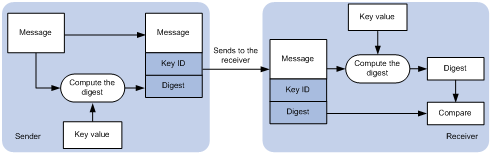
As shown in Figure 4-1, NTP authentication proceeds as follows:
1. The sender uses the key identified by the key ID to calculate a digest for the NTP message through the specified algorithm. Then it sends the calculated digest together with the NTP message and key ID to the receiver.
2. Upon receiving the message, the receiver performs the following actions:
a. Finds the key according to the key ID in the message.
b. Uses the key and the specified algorithm to calculate the digest for the message.
c. Compares the digest with the digest contained in the NTP message.
- If they are different, the receiver discards the message.
- If they are the same, the receiver determines whether the sender is allowed to use the authentication ID on the local end. If the sender is allowed to use the authentication ID, the receiver accepts the message. If the sender is not allowed to use the authentication ID, the receiver discards the message
Restrictions and guidelines
You can configure NTP authentication in client/server mode, symmetric active/passive mode, broadcast mode, or multicast mode. To ensure a successful NTP authentication, configure the same authentication key ID, algorithm, and key on the local device and time server. Make sure the time server is allowed to use the key ID for authentication on the local device.
NTP authentication results differ when different settings are configured on the local device and time server, as shown in Table 4-3, Table 4-4, Table 4-5, and Table 4-6. (N/A in the table means that whether the configuration is performed or not does not make any difference.)
Table 4-3 Results of NTP authentication in client/server mode
|
Client |
Server |
||||
|
Enable NTP authentication |
Specify the server and key |
Trusted key |
Enable NTP authentication |
Trusted key |
|
|
Successful authentication |
|||||
|
Yes |
Yes |
Yes |
Yes |
Yes |
|
|
Failed authentication |
|||||
|
Yes |
Yes |
Yes |
Yes |
No |
|
|
Yes |
Yes |
Yes |
No |
N/A |
|
|
Yes |
Yes |
No |
N/A |
N/A |
|
|
Authentication not performed |
|||||
|
Yes |
No |
N/A |
N/A |
N/A |
|
|
No |
N/A |
N/A |
N/A |
N/A |
|
Table 4-4 Results of NTP authentication in symmetric active/passive peer mode
|
Active peer |
Passive peer |
||||
|
Enable NTP authentication |
Specify the peer and key |
Trusted key |
Stratum level |
Enable NTP authentication |
Trusted key |
|
Successful authentication |
|||||
|
Yes |
Yes |
Yes |
N/A |
Yes |
Yes |
|
Failed authentication |
|||||
|
Yes |
Yes |
Yes |
N/A |
Yes |
No |
|
Yes |
Yes |
Yes |
N/A |
No |
N/A |
|
Yes |
No |
N/A |
N/A |
Yes |
N/A |
|
No |
N/A |
N/A |
N/A |
Yes |
N/A |
|
Yes |
Yes |
No |
Larger than the passive peer |
N/A |
N/A |
|
Yes |
Yes |
No |
Smaller than the passive peer |
Yes |
N/A |
|
Authentication not performed |
|||||
|
Yes |
No |
N/A |
N/A |
No |
N/A |
|
No |
N/A |
N/A |
N/A |
No |
N/A |
|
Yes |
Yes |
No |
Smaller than the passive peer |
No |
N/A |
Table 4-5 Results of NTP authentication in broadcast mode
|
Broadcast server |
Broadcast client |
|||
|
Enable NTP authentication |
Specify the server and key |
Trusted key |
Enable NTP authentication |
Trusted key |
|
Successful authentication |
||||
|
Yes |
Yes |
Yes |
Yes |
Yes |
|
Failed authentication |
||||
|
Yes |
Yes |
Yes |
Yes |
No |
|
Yes |
Yes |
Yes |
No |
N/A |
|
Yes |
Yes |
No |
Yes |
N/A |
|
Yes |
No |
N/A |
Yes |
N/A |
|
No |
N/A |
N/A |
Yes |
N/A |
|
Authentication not performed |
||||
|
Yes |
Yes |
No |
No |
N/A |
|
Yes |
No |
N/A |
No |
N/A |
|
No |
N/A |
N/A |
No |
N/A |
Table 4-6 Results of NTP authentication in multicast mode
|
Multicast server |
Multicast client |
|||
|
Enable NTP authentication |
Specify the server and key |
Trusted key |
Enable NTP authentication |
Trusted key |
|
Successful authentication |
||||
|
Yes |
Yes |
Yes |
Yes |
Yes |
|
Failed authentication |
||||
|
Yes |
Yes |
Yes |
Yes |
No |
|
Yes |
Yes |
Yes |
No |
N/A |
|
Yes |
Yes |
No |
Yes |
N/A |
|
Yes |
No |
N/A |
Yes |
N/A |
|
No |
N/A |
N/A |
Yes |
N/A |
|
Authentication not performed |
||||
|
Yes |
Yes |
No |
No |
N/A |
|
Yes |
No |
N/A |
No |
N/A |
|
No |
N/A |
N/A |
No |
N/A |
Examples
· Configuring NTP authentication in client/server mode
The following configuration example uses Device A as the client and Device B as the server.
a. Configure Device A.
# Enable NTP authentication.
<DeviceA> system-view
[DeviceA] ntp-service authentication enable
# Create a plaintext NTP authentication key, specifying the key ID as 42 and key value as aNiceKey.
[DeviceA] ntp-service authentication-keyid 42 authentication-mode md5 simple aNiceKey
# Configure key 42 as a trusted key.
[DeviceA] ntp-service reliable authentication-keyid 42
# Associate key 42 with NTP server 1.1.1.1 (IP address of Device B).
[DeviceA] ntp-service unicast-server 1.1.1.1 authentication-keyid 42
b. Configure Device B.
# Enable NTP authentication.
<DeviceB> system-view
[DeviceB] ntp-service authentication enable
# Create a plaintext NTP authentication key, specifying the key ID as 42 and key value as aNiceKey.
[DeviceB] ntp-service authentication-keyid 42 authentication-mode md5 simple aNiceKey
# Configure key 42 as a trusted key.
[DeviceB] ntp-service reliable authentication-keyid 42
· Configuring NTP authentication in symmetric active/passive mode
The following configuration example uses Device A as the active peer and Device B as the passive peer.
a. Configure Device A.
# Enable NTP authentication.
<DeviceA> system-view
[DeviceA] ntp-service authentication enable
# Create a plaintext NTP authentication key, specifying the key ID as 42 and key value as aNiceKey.
[DeviceA] ntp-service authentication-keyid 42 authentication-mode md5 simple aNiceKey
# Configure key 42 as a trusted key.
[DeviceA] ntp-service reliable authentication-keyid 42
# Associate key 42 with passive peer 1.1.1.1 (IP address of Device B).
[DeviceA] ntp-service unicast-peer 1.1.1.1 authentication-keyid 42
b. Configure Device B.
# Enable NTP authentication.
<DeviceB> system-view
[DeviceB] ntp-service authentication enable
# Create a plaintext NTP authentication key, specifying the key ID as 42 and key value as aNiceKey.
[DeviceB] ntp-service authentication-keyid 42 authentication-mode md5 simple aNiceKey
# Configure key 42 as a trusted key.
[DeviceB] ntp-service reliable authentication-keyid 42
· Configuring NTP authentication in broadcast mode
The following configuration example uses Device A as the broadcast client and Device B as the broadcast server.
a. Configure Device A.
# Enable NTP authentication.
<DeviceA> system-view
[DeviceA] ntp-service authentication enable
# Create a plaintext NTP authentication key, specifying the key ID as 42 and key value as aNiceKey.
[DeviceA] ntp-service authentication-keyid 42 authentication-mode md5 simple aNiceKey
# Configure key 42 as a trusted key.
[DeviceA] ntp-service reliable authentication-keyid 42
b. Configure Device B.
# Enable NTP authentication.
<DeviceB> system-view
[DeviceB] ntp-service authentication enable
# Create a plaintext NTP authentication key, specifying the key ID as 42 and key value as aNiceKey.
[DeviceB] ntp-service authentication-keyid 42 authentication-mode md5 simple aNiceKey
# Configure key 42 as a trusted key.
[DeviceB] ntp-service reliable authentication-keyid 42
# Configure Device B to operate in NTP broadcast server mode and associate key 42 with the broadcast server.
[DeviceB] interface gigabitethernet 1/0/1
[DeviceB-GigabitEthernet1/0/1] ntp-service broadcast-server authentication-keyid 42
· Configuring NTP authentication in multicast mode
The following configuration example uses Device A as the multicast client and Device B as the multicast server.
a. Configure Device A.
# Enable NTP authentication.
<DeviceA> system-view
[DeviceA] ntp-service authentication enable
# Create a plaintext NTP authentication key, specifying the key ID as 42 and key value as aNiceKey.
[DeviceA] ntp-service authentication-keyid 42 authentication-mode md5 simple aNiceKey
# Configure key 42 as a trusted key.
[DeviceA] ntp-service reliable authentication-keyid 42
b. Configure Device B.
# Enable NTP authentication.
<DeviceB> system-view
[DeviceB] ntp-service authentication enable
# Create a plaintext NTP authentication key, specifying the key ID as 42 and key value as aNiceKey.
[DeviceB] ntp-service authentication-keyid 42 authentication-mode md5 simple aNiceKey
# Configure key 42 as a trusted key.
[DeviceB] ntp-service reliable authentication-keyid 42
# Configure Device B to operate in multicast server mode and associate key 42 with the multicast server.
[DeviceB] interface vlan-interface 1
[DeviceB-Vlan-interface1] ntp-service multicast-server 224.0.1.1 authentication-keyid 42
Authenticating SNTP messages
Security threats
When the device uses SNTP for time synchronization, it might get time information from an unauthorized time server and synchronize to an incorrect time.
Hardening recommendations
To protect the device from an unauthorized time server, configure SNTP authentication. This feature authenticates SNTP messages for security purposes. The device receives an SNTP message and gets time synchronization information from it only when the message is authenticated. If the message fails authentication, the device discards the message. This function ensures that the device does not synchronize to an unauthorized time server.
Figure 4-2 SNTP authentication
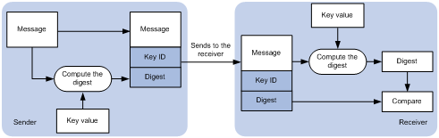
As shown in Figure 4-1, SNTP authentication proceeds as follows:
1. The sender uses the key identified by the key ID to calculate a digest for the SNTP message through the specified algorithm. Then it sends the calculated digest together with the SNTP message and key ID to the receiver.
2. Upon receiving the message, the receiver performs the following actions:
a. Finds the key according to the key ID in the message.
b. Uses the key and the specified algorithm to calculate the digest for the message.
c. Compares the digest with the digest contained in the SNTP message.
- If they are different, the receiver discards the message.
- If they are the same, the receiver determines whether the sender is allowed to use the authentication ID on the local end. If the sender is allowed to use the authentication ID, the receiver accepts the message. If the sender is not allowed to use the authentication ID, the receiver discards the message
Restrictions and guidelines
On the SNTP client, associate the specified key with the NTP server. Make sure the server is allowed to use the key ID for authentication on the client.
With authentication disabled, the SNTP client can synchronize with the NTP server regardless of whether the NTP server is enabled with authentication.
Examples
The following configuration example uses Device A as the SNTP client and Device B as the NTP server.
1. Configure Device A.
# Enable SNTP authentication.
<DeviceA> system-view
[DeviceA] sntp-service authentication enable
# Create a plaintext NTP authentication key, specifying the key ID as 42 and key value as aNiceKey.
[DeviceA] sntp-service authentication-keyid 42 authentication-mode md5 simple aNiceKey
# Configure key 42 as a trusted key.
[DeviceA] sntp-service reliable authentication-keyid 42
# Specify the NTP server (Device B) and associate key 42 with the NTP server.
[DeviceA] sntp-service unicast-server 1.1.1.1 authentication-keyid 42
2. Configure Device B.
# Enable NTP authentication.
<DeviceB> system-view
[DeviceB] ntp-service authentication enable
# Create a plaintext NTP authentication key, specifying the key ID as 42 and key value as aNiceKey
[DeviceB] ntp-service authentication-keyid 42 authentication-mode md5 simple aNiceKey
# Configure key 42 as a trusted key.
[DeviceB] ntp-service reliable authentication-keyid 42
5 Hardening the data plane
Security isolation
Configuring port isolation
Security threats
If one of the hosts connected to interfaces of a device has security threats and is attacked, the host might send a large number of unicast, multicast, or broadcast packets and even spread the virus to other hosts in the same VLAN. This will affect other hosts and occupy network bandwidth.
Hardening recommendations
To avoid this security threat, configure port isolation. Port isolation allows you to add interfaces to an isolation group. Interfaces in the same isolation group cannot communicate with each other at Layer 2. Therefore, the attack against an interface is limited to the scope of the interface, and the network security is improved.
For more information about port isolation, see Layer 2—LAN Switching Configuration Guide.
Configuring user isolation (Applicable only to devices with access controller functionality)
The user isolation feature isolates packets for users that use the same SSID or for users that are in the same VLAN. This feature improves user security, relieves the forwarding stress of the device, and reduces consumption of radio resources.
User isolation includes the following types:
· SSID-based user isolation—Isolates wireless users that use the same SSID.
· VLAN-based user isolation—Isolates wired or wireless users in the same VLAN.
For more information about user isolation, see configuring user isolation in the WLAN configuration guide in the H3C Unified Wired and Wireless Access Controller User Manual documentation set.
Remotely configuring UNI isolation on an EPON ONU
Security threats
If one of the hosts connected to UNIs of an ONU has security threats and is attacked, the host might send a large number of broadcast packets and even spread the virus to other hosts. This will affect other hosts and occupy network bandwidth.
Hardening recommendations
To avoid this security threat, enable UNI isolation. UNI isolation improves security and allows flexible networking schemes by isolating UNIs at Layer 2. UNIs in an isolation group cannot communicate with each other at Layer 2.
Examples
# Assign all UNIs on the ONU bound to ONU 1/0/1:1 to the isolation group.
<Sysname> system-view
[Sysname] interface onu 1/0/1:1
[Sysname-Onu1/0/1:1] onu port-isolate enable
# Assign UNIs 1 and 2 on the ONU bound to ONU 1/0/1:1 to the isolation group.
<Sysname> system-view
[Sysname] interface onu 1/0/1:1
[Sysname-Onu1/0/1:1] uni 1 port-isolate
[Sysname-Onu1/0/1:1] uni 2 port-isolate
Suppressing storms and controlling storms
Configuring storm suppression and storm control
Security threats
If the device receives broadcast, multicast, or unknown unicast traffic, it forwards the traffic to all interfaces except the receiving interface in the broadcast domain. This might cause broadcast storm, which degrades the forwarding performance of the device.
Hardening recommendations
Use storm suppression and storm control to monitor and control incoming broadcast, multicast, or unknown unicast traffic.
The storm suppression feature ensures that the size of a particular type of traffic (broadcast, multicast, or unknown unicast traffic) does not exceed the threshold on an interface. When the broadcast, multicast, or unknown unicast traffic on the interface exceeds this threshold, the system discards packets until the traffic drops below this threshold.
The storm control feature compares broadcast, multicast, and unknown unicast traffic regularly with their respective traffic thresholds. When a particular type of traffic exceeds its upper threshold on an interface, the device can block or shut down the interface and send logs or traps.
Restrictions and guidelines
For the traffic suppression result to be determined, do not configure storm control together with storm suppression for the same type of traffic.
Examples
# On GigabitEthernet 1/0/1, enable broadcast, multicast, and unknown unicast storm suppression, and set the suppression threshold for these types of traffic to 10000 kbps.
<Sysname> system-view
[Sysname] interface gigabitethernet 1/0/1
[Sysname-GigabitEthernet1/0/1] broadcast-suppression kbps 10000
[Sysname-GigabitEthernet1/0/1] multicast-suppression kbps 10000
[Sysname-GigabitEthernet1/0/1] unicast-suppression kbps 10000
# On GigabitEthernet 1/0/1, configure storm control as follows:
· Enable broadcast, multicast, and unicast storm control, and set the upper and lower thresholds for each type of traffic to 2000 kbps and 1500 kbps, respectively.
· Configure GigabitEthernet 1/0/1 to block a specific type of traffic when the type of traffic exceeds the upper storm control threshold.
· Enable GigabitEthernet 1/0/1 to output log messages when it detects storm control threshold events.
<Sysname> system-view
[Sysname] interface gigabitethernet 1/0/1
[Sysname-GigabitEthernet1/0/1] storm-constrain broadcast kbps 2000 1500
[Sysname-GigabitEthernet1/0/1] storm-constrain multicast kbps 2000 1500
[Sysname-GigabitEthernet1/0/1] storm-constrain unicast kbps 2000 1500
[Sysname-GigabitEthernet1/0/1] storm-constrain control block
[Sysname-GigabitEthernet1/0/1] storm-constrain enable log
# Set the broadcast, multicast, and unknown unicast suppression bandwidth all to 100 kbps for VSI vpn1.
<Sysname> system-view
[Sysname] vsi vpn1
[Sysname-vsi-vpn1] restrain broadcast 100
[Sysname-vsi-vpn1] restrain multicast 100
[Sysname-vsi-vpn1] restrain unknown-unicast 100
Dropping unknown multicast data packets
Security threats
Unknown multicast data refers to multicast data for which no forwarding entries exist in the IGMP snooping or MLD snooping forwarding table. If the device receives unknown multicast data, it floods the data in the VLAN or VSI to which the data belongs. This might causes broadcast storm, which degrades the forwarding performance of the device.
Hardening recommendations
To avoid broadcast storm caused by flooding unknown multicast data packets, enable the dropping unknown multicast data packets feature. This feature enables the device to forward unknown multicast data only to the router port. If the device does not have a router port, unknown multicast data will be dropped.
Examples
# In VLAN 2, enable IGMP snooping and dropping unknown multicast data packets.
<Sysname> system-view
[Sysname] igmp-snooping
[Sysname-igmp-snooping] quit
[Sysname] vlan 2
[Sysname-vlan2] igmp-snooping enable
[Sysname-vlan2] igmp-snooping drop-unknown
# In VLAN 2, enable MLD snooping and dropping unknown IPv6 multicast data packets.
<Sysname> system-view
[Sysname] mld-snooping
[Sysname-mld-snooping] quit
[Sysname] vlan 2
[Sysname-vlan2] mld-snooping enable
[Sysname-vlan2] mld-snooping drop-unknown
# In VSI aaa, enable IGMP snooping and dropping unknown IPv4 multicast data packets.
<Sysname> system-view
[Sysname] igmp-snooping
[Sysname-igmp-snooping] quit
[Sysname] vsi aaa
[Sysname-vsi-aaa] igmp-snooping enable
[Sysname-vsi-aaa] igmp-snooping drop-unknown
# In VSI aaa, enable MLD snooping and dropping unknown IPv6 multicast data packets.
<Sysname> system-view
[Sysname] mld-snooping
[Sysname-mld-snooping] quit
[Sysname] vsi aaa
[Sysname-vsi-aaa] mld-snooping enable
[Sysname-vsi-aaa] mld-snooping drop-unknown
MAC address security management
Configuring blackhole MAC address entries
Hardening recommendations
To block all frames destined for or sourced from a suspicious MAC address, configure the MAC address as a blackhole MAC address entry. The device drops all frames with a source or destination MAC address that matches a blackhole MAC address entry.
Examples
# Configure 000f-e201-0101 as a blackhole MAC address entry.
<Sysname> system-view
[Sysname] mac-address blackhole 000f-e201-0101 vlan 2
Disabling MAC address learning
Hardening recommendations
MAC address learning is enabled by default. To prevent the MAC address table from being saturated when the device is under attack, disable MAC address learning. For example, you can disable MAC address learning to prevent the device from being attacked by a large number of frames with different source MAC addresses.
Examples
# Disable global MAC address learning
<Sysname> system-view
[Sysname] undo mac-address mac-learning enable
# Disable MAC address learning on VLAN 10.
<Sysname> system-view
[Sysname] vlan 10
[Sysname-vlan10] undo mac-address mac-learning enable
# Disable MAC address learning on GigabitEthernet 1/0/1.
<Sysname> system-view
[Sysname] interface gigabitethernet 1/0/1
[Sysname-GigabitEthernet1/0/1] undo mac-address mac-learning enable
# Disable MAC address learning on VSI vpn1.
<Sysname> system-view
[Sysname] vsi vpn1
[Sysname-vsi-vpn1] undo mac-learning enable
Controlling and monitoring MAC address learning
Security threats
Malicious attackers could launch a source MAC address spoofing attack by flooding packets to a valid unicast destination, each with a different MAC source address. The MAC address table of the device would be quickly saturated with these illegitimate addresses, resulting in degraded forwarding performance and increased floods.
Hardening recommendations
To protect the device and the network from source MAC address spoofing attacks, set the MAC learning limit on ports. When the number of learned MAC address entries reaches the limit on a port, the device stops learning MAC address entries.
In addition, you can configure the actions to take after the MAC learning limit is reached, including:
· Disable forwarding unknown frames after the MAC learning limit is reached. (Unknown frames refer to frames whose source MAC addresses are not in the MAC address table.)
· Enable the MAC learning alarm feature. This feature generates a log message when the number of MAC address entries reaches the maximum or drops below 90% of the maximum.
Examples
# Configure the device to learn a maximum of 600 MAC address entries on interface GigabitEthernet 1/0/1. Disable the device from forwarding unknown frames received on the interface after the MAC learning limit on the interface is reached.
<Sysname> system-view
[Sysname] interface gigabitethernet 1/0/1
[Sysname-GigabitEthernet1/0/1] mac-address max-mac-count 600
[Sysname-GigabitEthernet1/0/1] undo mac-address max-mac-count enable-forwarding
# Configure the device to learn a maximum of 600 MAC address entries on VLAN 10. Disable the device from forwarding unknown frames received by interfaces in the VLAN after the MAC learning limit for the VLAN is reached.
<Sysname> system-view
[Sysname] vlan 10
[Sysname-vlan10] mac-address max-mac-count 600
[Sysname-vlan10] undo mac-address max-mac-count enable-forwarding
# In an EPON network, remotely set the MAC learning limit to 600 on UNI 1 of the ONU bound to ONU 1/0/1:1.
<Sysname> system-view
[Sysname] interface onu 1/0/1:1
[Sysname-Onu1/0/1:1] uni 1 mac-address max-mac-count 600
Assigning MAC learning priority to interfaces
Security threats
The downlink port on a switch might learn the MAC address of a gateway attached to an uplink port for the following reasons:
· The downlink port is in a loop.
· An attacker initiates a MAC address spoofing attack by sending a frame to the downlink port, with the gateway MAC address as the source MAC address.
Hardening recommendations
To prevent incorrect MAC address learning, assign high MAC learning priority to an uplink port and assign low MAC learning priority to a downlink port. The device will allow a low priority port to learn a MAC address only if that MAC address has not been learned on a high priority port.
Examples
# Assign high MAC learning priority to GigabitEthernet 1/0/1.
<Sysname> system-view
[Sysname] interface gigabitethernet 1/0/1
[Sysname-GigabitEthernet1/0/1] mac-address mac-learning priority high
Enabling MAC move notifications and suppression
Security threats
MAC move occurs when one port receives a frame with a source MAC address that has been learned on another port in the same VLAN. In this situation, the device updates the outgoing port in the MAC address entry.
Frequent MAC address moves occur if a Layer 2 loop or MAC address spoofing attack is present.
Hardening recommendations
To protect the device against Layer 2 loops and MAC address spoofing attacks:
· Enable MAC move notification to report the MAC move events to the information center module. The information center will output the events as log or SNMP notification messages depending on your configuration.
· Configure MAC address move suppression to shut down a port for a period if frequent MAC moves are detected on it. The port will automatically go up after the suppression interval expires. Alternatively, you can manually bring up the port.
Examples
# Enable MAC move notifications.
<Sysname> system-view
[Sysname] mac-address notification mac-move
# Enable MAC move suppression on GigabitEthernet 1/0/1.
<Sysname> system-view
[Sysname] interface gigabitethernet 1/0/1
[Sysname-GigabitEthernet1/0/1] mac-address notification mac-move suppression
Data flow protection
Configuring MACsec
Media Access Control Security (MACsec) secures data communication on the MAC sublayer of the data link layer. MACsec provides services such as data encryption, frame integrity check, and data origin validation.
MACsec provides the following mechanisms to secure frames:
· Data encryption—MACsec enables a port to encrypt outbound frames and decrypt MACsec-encrypted inbound frames. The keys for encryption and decryption are obtained through MKA negotiation.
· Integrity check—MACsec performs integrity check when the device receives a MACsec-encrypted frame. The integrity check uses the following process:
a. Uses a key negotiated by MKA to calculate an integrity check value (ICV) for the frame.
b. Compares the calculated ICV with the ICV in the frame trailer.
- If the ICVs are the same, the device determines that the frame is legal.
- If the ICVs are different, the device determines whether to drop the frame based on the validation mode.
· Replay protection—When MACsec frames are transmitted over the network, frame disorder might occur. MACsec replay protection allows the device to accept the out-of-order packets within the replay protection window size and drop other out-of-order packets.
For more information about MACsec, see Security Configuration Guide.
Configuring IPsec
IPsec provides interoperable, high-quality, cryptography-based security for IP communications. IPsec is a security framework that includes the following protocols:
· Authentication Header (AH).
· Encapsulating Security Payload (ESP).
· Internet Key Exchange (IKE).
· Internet Key Exchange Version 2 (IKEv2).
AH and ESP are security protocols that provide security services. IKE and IKEv2 implement automatic key exchange. For more information about IPsec, see Security Configuration Guide.
Securing EPON data transmission
Enabling downlink traffic encryption for an ONU
Security threats
In an EPON system, an OLT broadcasts downlink data to ONUs. Each ONU receives packets destined for it based on the LLID and drops the other packets. A malicious user might intercept the packets destined for other users.
Hardening recommendations
To protect user information against illegal access, enable encryption for the downlink traffic transmitted from the OLT to ONUs.
Examples
# Enable downlink traffic encryption for an ONU.
<Sysname> system-view
[Sysname] interface onu 1/0/1:1
[Sysname-Onu1/0/1:1] encryption enable
Setting the LLID key update interval
Security threats
In an EPON system, an OLT broadcasts downlink data to ONUs. A malicious user might intercept the packets destined for other users.
Hardening recommendations
To secure user data transmission, each LLID in an EPON system uses an independent key. The OLT periodically requests ONUs to update their LLID keys. Each ONU responds with a new LLID key after it receives the LLID key update request from the OLT. You can reduce the LLID key update interval to reduce the risk of key cracking.
Examples
# Set the LLID key update interval to 8 seconds.
<Sysname> system-view
[Sysname] ftth
[Sysname-ftth] encryption slot 1 update-time 8
Packet filtering & Traffic filtering
ACL
An access control list (ACL) is a set of rules for identifying traffic. ACLs work with other modules, such as packet filtering, QoS, and routing. These modules use ACLs to identify traffic and enforce predefined polices on the identified traffic to control network access and improve bandwidth efficiency.
Table 5-1 shows different ACL types based on criteria.
|
Type |
ACL number |
IP version |
Match criteria |
|
Basic ACLs |
2000 to 2999 |
IPv4 |
Source IPv4 address. |
|
IPv6 |
Source IPv6 address. |
||
|
Advanced ACLs |
3000 to 3999 |
IPv4 |
Source IPv4 address, destination IPv4 address, packet priority, protocol number, and other Layer 3 and Layer 4 header fields. |
|
IPv6 |
Source IPv6 address, destination IPv6 address, packet priority, protocol number, and other Layer 3 and Layer 4 header fields. |
||
|
Layer 2 ACLs |
4000 to 4999 |
IPv4 and IPv6 |
Layer 2 header fields, such as source and destination MAC addresses, 802.1p priority, and link layer protocol type. |
|
User-defined ACLs |
5000 to 5999 |
IPv4 and IPv6 |
User specified matching patterns in protocol headers. |
For more information about ACLs, see ACL and QoS Configuration Guide.
Traffic filtering
Security threats
The device might be overloaded or become abnormal due to external attacks, which eventually render services unavailable. This feature protects the network against attack traffic by denying the attack traffic.
Hardening recommendations
Traffic filtering is implemented through a QoS policy. You can takes a traffic filtering action (permit or deny) on a traffic class by applying the QoS policy to an interface, globally, or VLANs. For example, you can deny packets sourced from an IP address according to network status.
Examples
# Create advanced ACL 3000, and configure a rule to match packets with source IP address 10.0.0.2.
<Device> system-view
[Device] acl advanced 3000
[Device-acl-ipv4-adv-3000] rule permit ip source 10.0.0.2 0
[Device-acl-ipv4-adv-3000] quit
# Create a traffic class named classifier_1, and use ACL 3000 as the match criterion in the traffic class.
[Device] traffic classifier classifier_1
[Device-classifier-classifier_1] if-match acl 3000
[Device-classifier-classifier_1] quit
# Create a traffic behavior named behavior_1, and configure the traffic filtering action to drop packets.
[Device] traffic behavior behavior_1
[Device-behavior-behavior_1] filter deny
[Device-behavior-behavior_1] quit
# Create a QoS policy named policy, and associate traffic class classifier_1 with traffic behavior behavior_1 in the QoS policy.
[Device] qos policy policy
[Device-qospolicy-policy] classifier classifier_1 behavior behavior_1
[Device-qospolicy-policy] quit
# Apply QoS policy policy to the incoming traffic of GigabitEthernet 1/0/1.
[Device] interface gigabitethernet 1/0/1
[Device-GigabitEthernet1/0/1] qos apply policy policy inbound
Configuring IP source guard
IP source guard (IPSG) prevents spoofing attacks by using an IPSG binding table to filter out illegitimate packets.
This feature is typically configured on user-side interfaces.
For more information about IPSG, see IP source guard configuration in Security Configuration Guide.
Configuring IP source guard (Applicable only to devices with access controller functionality)
IP source guard (IPSG) prevents spoofing attacks by using WLAN snooping entries to filter packets received by an AP. It drops packets that do not match the entries.
WLAN snooping is enabled by default on the AP. A WLAN snooping entry is an IP-MAC binding.
· In an IPv4 network, WLAN snooping reads the clients' IP-MAC bindings from the ARP messages or DHCP packets that pass through the AP. IPSG uses only the WLAN snooping entries obtained through DHCP packets.
· In an IPv6 network, WLAN snooping reads the clients' IP-MAC bindings from packets that pass through the AP. The packets are RA messages, NS messages, NA messages, and DHCP packets. IPSG uses all WLAN snooping entries for packet filtering.
For more information about IPSG, see configuring IP source guard in WLAN configuration guide in the H3C Unified Wired and Wireless Access Controller User Manual documentation set.
ASPF
A packet-filter firewall permits only trusted traffic. For a device to receive the return traffic for its requests, a packet-filter firewall must permit both the request and return traffic. In this situation, a malicious user might send attack packets or illegal requests to the device.
Advanced Stateful Packet Filter (ASPF) addresses the issues that a packet-filter firewall cannot solve. At the border of a network, ASPF can work with a packet-filter firewall to provide the network with a more comprehensive security policy that better meets the actual needs. The packet-filter firewall permits or denies packets according to ACL rules. The ASPF records information about the permitted packets to ensure that their return packets can pass through the packet-filter firewall.
For more information about ASPF, see Security Configuration Guide.
MFF
To implement Layer 2 isolation and Layer 3 communication between hosts in the same broadcast domain, use MAC-forced forwarding (MFF).
An MFF-enabled device intercepts ARP requests and returns the MAC address of a gateway (or server) to the senders. In this way, the senders are forced to send packets to the gateway for traffic monitoring and attack prevention.
For more information about MFF, see Security Configuration Guide.
uRPF
Attackers send packets with a forged source address to access a system that uses IPv4-based authentication, in the name of authorized users or even the administrator. Even if the attackers or other hosts cannot receive any response packets, the attacks are still disruptive to the attacked target.
Attackers can also send packets with different forged source addresses or attack multiple servers simultaneously to block connections or even break down the network.
To prevent these source address spoofing attacks, use uRPF. This feature checks whether an interface that receives a packet is the output interface of the FIB entry that matches the source address of the packet. If not, uRPF considers it a spoofing attack and discards the packet.
For more information about uRPF, see Security Configuration Guide.
SAVI
Source Address Validation Improvement (SAVI) checks the validity of the source addresses of global unicast IPv6 packets. It implements the validity check by using ND snooping, DHCPv6 snooping, and static IPv6SG address bindings of IP source guard. SAVI checks only global unicast addresses and forwards the packets that pass the validity check. Packets sourced from an invalid address are dropped.
For more information about SAVI, see Security Configuration Guide.
Configuring the voice VLAN security mode
Security threats
When voice VLAN operates in normal mode, the port receives voice-VLAN-tagged packets and forwards them in the voice VLAN without examining their MAC addresses. If the PVID of the port is the voice VLAN and the port operates in manual VLAN assignment mode, the port forwards all the received untagged packets in the voice VLAN. In this mode, voice VLANs are vulnerable to traffic attacks. Malicious users might send a large number of forged voice-VLAN-tagged or untagged packets to affect voice communication.
Hardening recommendations
To protect voice traffic in an unsafe network, you can configure the voice VLANs to operate in security mode. In this mode, the port uses the source MAC addresses of voice packets to match the OUI addresses of the device. Packets that fail the match will be dropped. The security mode improves the security.
Restrictions and guidelines
As a best practice, do not transmit both voice traffic and non-voice traffic in a voice VLAN. If you must transmit different traffic in a voice VLAN, make sure the voice VLAN security mode is disabled.
Examples
# Enable the voice VLAN security mode.
<Sysname> system-view
[Sysname] voice-vlan security enable
Attack detection and defense
DoS attack detection and defense
The gateway device deployed on the public network and its downstream hosts and servers are vulnerable to DoS attacks. Victim devices cannot respond to user requests normally.
The device supports prevents the following DoS attacks:
· Single-packet attacks—ICMP redirect, ICMP destination unreachable, ICMP type, ICMPv6 type, Land, large ICMP packet, large ICMPv6 packet, IP options, IP option abnormal, IP fragment, IP impossible packet, tiny fragment, smurf, TCP flag, Traceroute, Winnuke, UDP bomb, UDP snork, UDP fraggle, Teardrop, ping of death, and IPv6 ext-header abnormal.
· Scanning attacks—IP sweep, port scan, and distributed port scan.
· Flooding attacks—SYN flood, ACK flood, SYN-ACK flood, FIN flood, RST flood, DNS flood, DNS reply flood, HTTP flood, SIP flood, ICMP flood, ICMPv6 flood, and UDP flood.
For more information about DoS attack detection and prevention, see Attack Detection and Prevention in Security Configuration Guide.
Naptha attack prevention
Naptha is a DDoS attack that targets operating systems. It exploits the resources consuming vulnerability in TCP/IP stack and network application process. The attacker establishes a large number of TCP connections in a short period of time and leaves them in certain states without requesting any data. These TCP connections starve the victim of system resources, resulting in a system breakdown.
After you enable Naptha attack prevention, the device periodically checks the number of TCP connections in each state (CLOSING, ESTABLISHED, FIN_WAIT_1, FIN_WAIT_2, and LAST_ACK). If the number of TCP connections in a state exceeds the limit, the device will accelerate the aging of the TCP connections in that state to mitigate the Naptha attack.
For more information about Naptha attack prevention, see TCP attack prevention in Security Configuration Guide.
