| Title | Size | Downloads |
|---|---|---|
| Interoperation Guide For H3C Switches and Third-Party Switches-6W100-book.pdf | 1.01 MB |
- Table of Contents
- Related Documents
-
Interoperation Guide
For H3C Switches and Third-Party Switches
Document version: 6W100-20220729
Copyright © 2022 New H3C Technologies Co., Ltd. All rights reserved.
No part of this manual may be reproduced or transmitted in any form or by any means without prior written consent of New H3C Technologies Co., Ltd.
Except for the trademarks of New H3C Technologies Co., Ltd., any trademarks that may be mentioned in this document are the property of their respective owners.
The information in this document is subject to change without notice.
This document describes the interoperation between H3C switches and third-party devices, as well as configuration of the associated parameters for interoperation.
This preface includes the following topics about the documentation:
· Audience
This documentation is intended for:
· Network planners.
· Network administrators working with the switches.
The following information describes the conventions used in the documentation.
Symbols
|
Convention |
Description |
|
|
An alert that calls attention to important information that if not understood or followed can result in personal injury. |
|
|
An alert that calls attention to important information that if not understood or followed can result in data loss, data corruption, or damage to hardware or software. |
|
|
An alert that calls attention to essential information. |
|
NOTE |
An alert that contains additional or supplementary information. |
|
|
An alert that provides helpful information. |
Network topology icons
|
|
Represents a generic network device, such as a router, switch, or firewall. |
|
|
Represents a routing-capable device, such as a router or Layer 3 switch. |
|
|
Represents a generic switch, such as a Layer 2 or Layer 3 switch, or a router that supports Layer 2 forwarding and other Layer 2 features. |
|
|
Represents an access controller, a unified wired-WLAN module, or the access controller engine on a unified wired-WLAN switch. |
|
|
Represents an access point. |
|
|
Wireless terminator unit. |
|
|
Wireless terminator. |
|
|
Represents a mesh access point. |
|
|
Represents omnidirectional signals. |
|
|
Represents directional signals. |
|
|
Represents a security product, such as a firewall, UTM, multiservice security gateway, or load balancing device. |
|
|
Represents a security module, such as a firewall, load balancing, NetStream, SSL VPN, IPS, or ACG module. |
Examples provided in this document
Examples in this document might use devices that differ from your device in hardware model, configuration, or software version. It is normal that the port numbers, sample output, screenshots, and other information in the examples differ from what you have on your device.
Procedures and information in the examples might be slightly different depending on the software or hardware version of the products.
The configuration examples were created and verified in a lab environment, and all the devices were started with the factory default configuration. When you are working on a live network, make sure you understand the potential impact of every command on your network.
You can email your comments about product documentation to [email protected].
We appreciate your comments.
Contents
EVPN and VXLAN interoperation guide
Interoperation with Cisco devices
Example: Configuring IBGP for interoperation
Example: Configuring EBGP for interoperation
Interoperation with Huawei devices
Example: Configuring IBGP for interoperation
Example: Configuring EBGP for interoperation
Interoperation with Ruijie devices
Example: Configuring IBGP for interoperation
Example: Configuring EBGP for interoperation
MSTP/PVST interoperation guide
Interoperation with Cisco devices
Interoperation with Huawei devices
Interoperation with Ruijie devices
LACP link aggregation interoperation guide
Interoperation with Cisco devices
Example: Configuring static link aggregation for interoperation
Example: Configuring dynamic link aggregation for interoperation
Interoperation with Huawei devices
Example: Configuring static link aggregation for interoperation
Example: Configuring dynamic link aggregation for interoperation
Interoperation with Ruijie devices
Example: Configuring static link aggregation for interoperation
Example: Configuring dynamic link aggregation for interoperation
Interoperation with Cisco devices
Interoperation with Huawei devices
Interoperation with Ruijie devices
Interoperation with Cisco devices
Example: Configuring NTP interoperation with a Cisco device
Interoperation with Huawei devices
Example: Configuring NTP interoperation with a Huawei device
Interoperation with Ruijie devices
Example: Configuring NTP interoperation with a Ruijie device
Interoperation with Cisco devices
Example: Configuring LLDP interoperation with a Cisco device
Interoperation with Huawei devices
Example: Configuring LLDP interoperation with a Huawei device
Interoperation with Ruijie devices
Configuring LLDP interoperation with a Ruijie device
Interoperation with Cisco devices
Interoperation with Huawei devices
Interoperation with Ruijie devices
Interoperation with Cisco devices
Example: Configuring static routing and BFD association for interoperation
Example: Configuring OSPF and BFD association for interoperation
Example: Configuring IS-IS and BFD association for interoperation
Example: Configuring BGP and BFD association for interoperation
Interoperation with Huawei devices
Example: Configuring static routing and BFD association for interoperation
Example: Configuring OSPF and BFD association for interoperation
Example: Configuring IS-IS and BFD association for interoperation
Example: Configuring BGP and BFD association for interoperation
Interoperation with Ruijie devices
Example: Configuring static routing and BFD association for interoperation
Example: Configuring OSPF and BFD association for interoperation
Example: Configuring IS-IS and BFD association for interoperation
Example: Configuring BGP and BFD association for interoperation
EVPN and VXLAN interoperation guide
Interoperation with Cisco devices
Interoperability analysis
Table 1 EVPN and VXLAN interoperability analysis
|
H3C |
Cisco |
Interoperability |
|
Supported |
Supported |
Supported |
Example: Configuring IBGP for interoperation
Network configuration
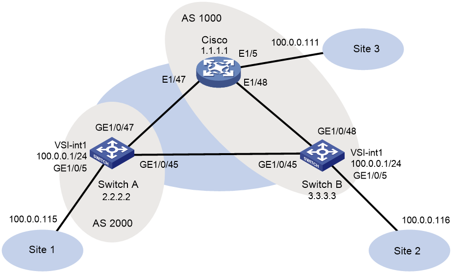
As shown in Figure 1, configure the H3C and Cisco devices as follows:
· Configure H3C devices Switch A and Switch B as distributed EVPN gateways.
· Configure the Cisco device as an RR to reflect BGP routes.
· Configure EVPN to provide Layer 2 connectivity within the same VXLAN and Layer 3 connectivity among different VXLANs.

Procedure
· Configure H3C device (Switch A)
# Enable L2VPN.
<SwitchA> system-view
[SwitchA] l2vpn enable
# Set the VXLAN hardware resource mode.
[SwitchA] hardware-resource vxlan border40k
# Disable remote MAC address learning and remote ARP learning.
[SwitchA] vxlan tunnel mac-learning disable
[SwitchA] vxlan tunnel arp-learning disable
# Configure OSPF.
[SwitchA] ospf 1
[SwitchA-ospf-1] area 0
[SwitchA-ospf-1-area-0.0.0.0] quit
[SwitchA-ospf-1] quit
# Configure interface Loopback 0.
[SwitchA] interface LoopBack 0
[SwitchA-LoopBack0] ip address 2.2.2.2 32
[SwitchA-LoopBack0] ospf 1 area 0
[SwitchA-LoopBack0] quit
# Configure the underlay network.
[SwitchA] interface GigabitEthernet 1/0/45
[SwitchA-GigabitEthernet1/0/45] port link-mode route
[SwitchA-GigabitEthernet1/0/45] ip address 13.0.0.1 255.255.255.252
[SwitchA-GigabitEthernet1/0/45] ospf 1 area 0.0.0.0
[SwitchA-GigabitEthernet1/0/45] quit
[SwitchA] interface GigabitEthernet 1/0/47
[SwitchA-GigabitEthernet1/0/47] port link-mode route
[SwitchA-GigabitEthernet1/0/47] ip address 11.0.0.2 255.255.255.252
[SwitchA-GigabitEthernet1/0/47] ospf 1 area 0.0.0.0
[SwitchA-GigabitEthernet1/0/47] quit
# Create VLAN 1001.
[SwitchA] vlan 1001
[SwitchA-vlan1001] quit
# Create an EVPN instance on VSI v1, and configure an RD and RTs for the EVPN instance.
[SwitchA] vsi v1
[SwitchA-vsi-v1] arp suppression enable
[SwitchA-vsi-v1] flooding disable all
[SwitchA-vsi-v1] evpn encapsulation vxlan
[SwitchA-vsi-v1-evpn-vxlan] route-distinguisher 2.2.2.2:10001
[SwitchA-vsi-v1-evpn-vxlan] vpn-target 65001:10001
[SwitchA-vsi-v1-evpn-vxlan] quit
# Create VXLAN10001.
[SwitchA-vsi-v1] vxlan 10001
[SwitchA-vsi-v1-vxlan-10001] quit
[SwitchA-vsi-v1] quit
# Configure BGP to advertise EVPN routes.
[SwitchA] bgp 65001
[SwitchA-bgp-default] peer 1.1.1.1 as-number 65001
[SwitchA-bgp-default] peer 1.1.1.1 connect-interface loopback 0
[SwitchA-bgp-default] address-family l2vpn evpn
[SwitchA-bgp-default-evpn] peer 1.1.1.1 enable
[SwitchA-bgp-default-evpn] quit
[SwitchA-bgp-default] quit
# On GigabitEthernet 1/0/5, create Ethernet service instance 1 to match VLAN 1001.
[SwitchA] interface gigabitethernet 1/0/5
[SwitchA-GigabitEthernet1/0/5] service-instance 1
[SwitchA-GigabitEthernet1/0/5-srv1] encapsulation s-vid 1001
# Map Ethernet service instance 1 to VSI v1.
[SwitchA-GigabitEthernet1/0/5-srv1] xconnect vsi v1
[SwitchA-GigabitEthernet1/0/5-srv1] quit
# Configure RD and RTs for VPN instance vpn1.
[SwitchA] ip vpn-instance vpn1
[SwitchA-vpn-instance-vpn1] route-distinguisher 2.2.2.2:10001
[SwitchA-vpn-instance-vpn1] vpn-target 65001:10001
[SwitchA-vpn-instance-vpn1] address-family evpn
[SwitchA-vpn-evpn-vpn1] vpn-target 65001:10001
[SwitchA-vpn-evpn-vpn1] quit
[SwitchA-vpn-instance-vpn1] quit
# Configure VSI-interface 1.
[SwitchA] interface vsi-interface 1
[SwitchA-Vsi-interface1] ip binding vpn-instance vpn1
[SwitchA-Vsi-interface1] ip address 100.0.0.1 255.255.255.0
[SwitchA-Vsi-interface1] mac-address 0000-2017-0001
[SwitchA-Vsi-interface1] distributed-gateway local
[SwitchA-Vsi-interface1] quit
# Create VSI-interface 16777201 and associate it with VPN instance vpn1 and L3VNI 16777201.
[SwitchA] interface vsi-interface 16777201
[SwitchA-Vsi-interface3] ip binding vpn-instance vpn1
[SwitchA-Vsi-interface3] l3-vni 16777201
[SwitchA-Vsi-interface3] quit
# Specify gateway interface VSI-interface 1 for VXLAN 10.
[SwitchA] vsi v1
[SwitchA-vsi-v1] gateway vsi-interface 1
[SwitchA-vsi-v1] quit
· Configure H3C device (Switch B)
# Enable L2VPN.
<SwitchB> system-view
[SwitchB] l2vpn enable
# Set the VXLAN hardware resource mode.
[SwitchB] hardware-resource vxlan border40k
# Disable remote MAC address learning and remote ARP learning.
[SwitchB] vxlan tunnel mac-learning disable
[SwitchB] vxlan tunnel arp-learning disable
# Configure OSPF.
[SwitchB] ospf 1
[SwitchB-ospf-1] area 0
[SwitchB-ospf-1-area-0.0.0.0] quit
[SwitchB-ospf-1] quit
# Configure interface Loopback 0.
[SwitchB] interface LoopBack 0
[SwitchB-LoopBack0] ip address 3.3.3.3 32
[SwitchB-LoopBack0] ospf 1 area 0
[SwitchB-LoopBack0] quit
# Configure the underlay network.
[SwitchB] interface GigabitEthernet 1/0/45
[SwitchB-GigabitEthernet1/0/45] port link-mode route
[SwitchB-GigabitEthernet1/0/45] ip address 13.0.0.2 255.255.255.252
[SwitchB-GigabitEthernet1/0/45] ospf 1 area 0.0.0.0
[SwitchB-GigabitEthernet1/0/45] quit
[SwitchB] interface GigabitEthernet 1/0/48
[SwitchB-GigabitEthernet1/0/48] port link-mode route
[SwitchB-GigabitEthernet1/0/48] ip address 12.0.0.2 255.255.255.252
[SwitchB-GigabitEthernet1/0/48] ospf 1 area 0.0.0.0
[SwitchB-GigabitEthernet1/0/48] quit
# Create VLAN 1001.
[SwitchB] vlan 1001
[SwitchB-vlan1001] quit
# Create an EVPN instance on VSI v1, and configure an RD and RTs for the EVPN instance.
[SwitchB] vsi v1
[SwitchB-vsi-v1] arp suppression enable
[SwitchB-vsi-v1] flooding disable all
[SwitchB-vsi-v1] evpn encapsulation vxlan
[SwitchB-vsi-v1-evpn-vxlan] route-distinguisher 3.3.3.3:10001
[SwitchB-vsi-v1-evpn-vxlan] vpn-target 65001:10001
[SwitchB-vsi-v1-evpn-vxlan] quit
# Create VXLAN 10001.
[SwitchB-vsi-v1] vxlan 10001
[SwitchB-vsi-v1-vxlan-10001] quit
[SwitchB-vsi-v1] quit
# Configure BGP to advertise EVPN routes.
[SwitchB] bgp 65001
[SwitchB-bgp-default] peer 1.1.1.1 as-number 65001
[SwitchB-bgp-default] peer 1.1.1.1 connect-interface loopback 0
[SwitchB-bgp-default] address-family l2vpn evpn
[SwitchB-bgp-default-evpn] peer 1.1.1.1 enable
[SwitchB-bgp-default-evpn] quit
[SwitchB-bgp-default] quit
# On GigabitEthernet 1/0/5, create Ethernet service instance 1 to match VLAN 1001.
[SwitchB] interface gigabitethernet 1/0/5
[SwitchB-GigabitEthernet1/0/5] service-instance 1
[SwitchB-GigabitEthernet1/0/5-srv1] encapsulation s-vid 1001
# Map Ethernet service instance 1 to VSI v1.
[SwitchB-GigabitEthernet1/0/5-srv1] xconnect vsi v1
[SwitchB-GigabitEthernet1/0/5-srv1] quit
# Configure RD and RTs for VPN instance vpn1.
[SwitchB] ip vpn-instance vpn1
[SwitchB-vpn-instance-vpn1] route-distinguisher 3.3.3.3:10001
[SwitchB-vpn-instance-vpn1] vpn-target 65001:10001
[SwitchB-vpn-instance-vpn1] address-family evpn
[SwitchB-vpn-evpn-vpn1] vpn-target 65001:10001
[SwitchB-vpn-evpn-vpn1] quit
[SwitchB-vpn-instance-vpn1] quit
# Configure VSI-interface 1.
[SwitchB] interface vsi-interface 1
[SwitchB-Vsi-interface1] ip binding vpn-instance vpn1
[SwitchB-Vsi-interface1] ip address 100.0.0.1 255.255.255.0
[SwitchB-Vsi-interface1] mac-address 0000-2017-0001
[SwitchB-Vsi-interface1] distributed-gateway local
[SwitchB-Vsi-interface1] quit
# Create VSI-interface 16777201 and associate it with VPN instance vpn1 and L3VNI 16777201.
[SwitchB] interface vsi-interface 16777201
[SwitchB-Vsi-interface3] ip binding vpn-instance vpn1
[SwitchB-Vsi-interface3] l3-vni 16777201
[SwitchB-Vsi-interface3] quit
# Specify gateway interface VSI-interface 1 for VXLAN 10.
[SwitchB] vsi v1
[SwitchB-vsi-v1] gateway vsi-interface 1
[SwitchB-vsi-v1] quit
· Configure the Cisco device
# View device information. Nexus9000 93180YC-EX is used as an example.
Cisco# show version
Cisco Nexus Operating System (NX-OS) Software
TAC support: http://www.cisco.com/tac
Copyright (C) 2002-2016, Cisco and/or its affiliates.
All rights reserved.
The copyrights to certain works contained in this software are
owned by other third parties and used and distributed under their own
licenses, such as open source. This software is provided "as is," and unless
otherwise stated, there is no warranty, express or implied, including but not
limited to warranties of merchantability and fitness for a particular purpose.
Certain components of this software are licensed under
the GNU General Public License (GPL) version 2.0 or
GNU General Public License (GPL) version 3.0 or the GNU
Lesser General Public License (LGPL) Version 2.1 or
Lesser General Public License (LGPL) Version 2.0.
A copy of each such license is available at
http://www.opensource.org/licenses/gpl-2.0.php and
http://opensource.org/licenses/gpl-3.0.html and
http://www.opensource.org/licenses/lgpl-2.1.php and
http://www.gnu.org/licenses/old-licenses/library.txt.
Software
BIOS: version 07.56
NXOS: version 7.0(3)I4(2)
BIOS compile time: 06/08/2016
NXOS image file is: bootflash:///nxos.7.0.3.I4.2.bin
NXOS compile time: 7/21/2016 8:00:00 [07/21/2016 16:09:32]
Hardware
cisco Nexus9000 93180YC-EX chassis
Intel(R) Xeon(R) CPU @ 1.80GHz with 24634044 kB of memory.
Processor Board ID FDO20380BK7
Device name: CN93
bootflash: 53298520 kB
Kernel uptime is 1 day(s), 1 hour(s), 19 minute(s), 35 second(s)
Last reset at 776030 usecs after Wed Sep 20 02:52:01 2017
Reason: Reset Requested by CLI command reload
System version: 7.0(3)I4(2)
Service:
plugin
Core Plugin, Ethernet Plugin
# Switch the resource mode.
Cisco# configure terminal
Enter configuration commands, one per line. End with CNTL/Z.
Cisco(config)# system routing template-vxlan-scale
# Enable features required for network communication.
Cisco(config)#
Cisco(config)# nv overlay evpn
Cisco(config)# feature ospf
Cisco(config)# feature bgp
Cisco(config)# feature interface-vlan
Cisco(config)# feature lldp
Cisco(config)# feature vn-segment-vlan-based
Cisco(config)# feature nv overlay
# Create VLAN 101 and VLAN 1001.
Cisco(config)# vlan 101 ,1001
Cisco(config-vlan)# exit
# Configure the gateway MAC address.
Cisco(config)# fabric forwarding anycast-gateway-mac 0000.2017.0001
# Disable IGMP snooping.
Cisco(config)# no ip igmp snooping
# Create VN segment 16777201.
Cisco(config)# vlan 101
Cisco(config-vlan)# vn-segment 16777201
Cisco(config-vlan)# exit
# Create VN segment 10001.
Cisco(config)# vlan 1001
Cisco(config-vlan)# vn-segment 10001
Cisco(config-vlan)# exit
# Enable OSPF.
Cisco(config)# router ospf 1
Cisco(config-router)# exit
# Create a VRF.
Cisco(config)# vrf context vpn1
Cisco(config-vrf)# vni 16777201
Cisco(config-vrf)# rd 1.1.1.1:10001
Cisco(config-vrf)# address-family ipv4 unicast
Cisco(config-vrf-af-ipv4)# route-target import 65001:10001
Cisco(config-vrf-af-ipv4)# route-target import 65001:10001 evpn
Cisco(config-vrf-af-ipv4)# route-target export 65001:10001
Cisco(config-vrf-af-ipv4)# route-target export 65001:10001 evpn
Cisco(config-vrf-af-ipv4)# exit
Cisco(config-vrf)# exit
# Create VLAN-interface 101.
Cisco(config)# interface vlan 101
Cisco(config-if)# no shutdown
Cisco(config-if)# vrf member vpn1
Warning: Deleted all L3 config on interface Vlan101
Cisco(config-if)# exit
# Create VLAN-interface 1001.
Cisco(config)# interface vlan 1001
Cisco(config-if)# no shutdown
Cisco(config-if)# vrf member vpn1
Warning: Deleted all L3 config on interface Vlan1001
Cisco(config-if)# ip address 100.0.0.1/24
Cisco(config-if)# fabric forwarding mode anycast-gateway
Cisco(config-if)# exit
# Create interface nve1.
Cisco(config)# interface nve1
Cisco(config-if-nve)# no shutdown
Cisco(config-if-nve)# source-interface loopback0
Cisco(config-if-nve)# host-reachability protocol bgp
Cisco(config-if-nve)# member vni 10001
Cisco(config-if-nve-vni)# suppress-arp
Cisco(config-if-nve-vni)# ingress-replication protocol bgp
Cisco(config-if-nve-vni)# exit
Cisco(config-if-nve)# member vni 16777201 associate-vrf
Cisco(config-if-nve)# exit
# Configure the site-facing interface.
Cisco(config)# interface ethernet 1/5
Cisco(config-if)# switchport
Cisco(config-if)# switchport mode trunk
Cisco(config-if)# switchport trunk allowed vlan 1001
Cisco(config-if)# no shutdown
Cisco(config-if)# exit
# Configure the underlay network.
Cisco(config)# interface ethernet 1/47
Cisco(config-if)# ip address 11.0.0.1/30
Cisco(config-if)# ip router ospf 1 area 0.0.0.0
Cisco(config-if)# no shutdown
Cisco(config-if)# exit
Cisco(config)# interface ethernet 1/48
Cisco(config-if)# ip address 12.0.0.1/30
Cisco(config-if)# ip router ospf 1 area 0.0.0.0
Cisco(config-if)# no shutdown
Cisco(config-if)# exit
# Create Loopback 0.
Cisco(config)# interface loopback0
Cisco(config-if)# ip address 1.1.1.1/32
Cisco(config-if)# ip router ospf 1 area 0.0.0.0
Cisco(config-if)# exit
# Configure BGP.
Cisco(config)# router bgp 65001
Cisco(config-router)# router-id 1.1.1.1
Cisco(config-router)# address-family l2vpn evpn
Cisco(config-router-af)# neighbor 2.2.2.2
Cisco(config-router-neighbor)# remote-as 65001
Cisco(config-router-neighbor)# update-source loopback 0
Cisco(config-router-neighbor)# address-family ipv4 unicast
Cisco(config-router-neighbor-af)# send-community both
Cisco(config-router-neighbor-af)# route-reflector-client
Cisco(config-router-neighbor-af)# exit
Cisco(config-router-neighbor)# address-family l2vpn evpn
Cisco(config-router-neighbor-af)# send-community both
Cisco(config-router-neighbor-af)# route-reflector-client
Cisco(config-router-neighbor-af)#
Cisco(config-router-neighbor-af)# exit
Cisco(config-router-neighbor)# exit
Cisco(config-router)# neighbor 3.3.3.3
Cisco(config-router-neighbor)# remote-as 65001
Cisco(config-router-neighbor)# update-source loopback 0
Cisco(config-router-neighbor)# address-family ipv4 unicast
Cisco(config-router-neighbor-af)# send-community both
Cisco(config-router-neighbor-af)# route-reflector-client
Cisco(config-router-neighbor-af)# exit
Cisco(config-router-neighbor)# address-family l2vpn evpn
Cisco(config-router-neighbor-af)# send-community both
Cisco(config-router-neighbor-af)# route-reflector-client
Cisco(config-router-neighbor-af)# exit
Cisco(config-router-neighbor)# exit
Cisco(config-router)# exit
# Configure EVPN.
Cisco(config)# evpn
Cisco(config-evpn)# vni 10001 l2
Cisco(config-evpn-evi)# rd 1.1.1.1:10001
Cisco(config-evpn-evi)# route-target both 65001:10001
Cisco(config-evpn-evi)# exit
Cisco(config-evpn)# exit
Verifying the configuration
· H3C device (Switch A)
# Verify that BGP L2VPN peers are connected.
[SwitchA] display bgp peer l2vpn evpn
BGP local router ID: 2.2.2.2
Local AS number: 65001
Total number of peers: 1 Peers in established state: 1
* - Dynamically created peer
Peer AS MsgRcvd MsgSent OutQ PrefRcv Up/Down State
1.1.1.1 65001 168 185 0 8 02:12:37 Established
# Verify that IPv4 neighbors have been discovered through inclusive multicast Ethernet tag (IMET) routes.
[SwitchA] display evpn auto-discovery imet
Total number of automatically discovered peers: 2
VSI name: v1
RD PE_address Tunnel_address Tunnel mode VXLAN ID
1.1.1.1:10001 1.1.1.1 1.1.1.1 VXLAN 10001
3.3.3.3:10001 3.3.3.3 3.3.3.3 VXLAN 10001
# Verify that EVPN routes have been learned for VPN instance vpn1.
[SwitchA] display evpn routing-table vpn-instance vpn1
VPN instance: vpn1 Local L3VNI: 16777201
IP address Next hop Outgoing interface NibID
100.0.0.111 1.1.1.1 Vsi-interface16777201 0x18000000
100.0.0.116 3.3.3.3 Vsi-interface16777201 0x18000001
# Verify that the device has learned EVPN ARP entries.
[SwitchA] display evpn route arp
Flags: D - Dynamic B - BGP L - Local active
G - Gateway S - Static M - Mapping
VPN instance: vpn1 Interface: Vsi-interface1
IP address MAC address Router MAC VSI index Flags
100.0.0.1 0000-2017-0001 703d-15b5-1c8d 0 GL
100.0.0.111 0000-1ed4-45a1 006b-f183-c327 0 B
100.0.0.115 0000-32eb-e6bc 703d-15b5-1c8d 0 DL
100.0.0.116 0000-1279-80ce 703d-15b5-1cff 0 B
# Verify that the device has learned IPv4 EVPN MAC entries.
[SwitchA] display evpn route mac
Flags: D - Dynamic B - BGP L - Local active
G - Gateway S - Static M - Mapping
VSI name: v1
MAC address Link ID/Name Flags Next hop
0005-0000-0001 Tunnel1 B 1.1.1.1
0000-1279-80ce Tunnel0 B 3.3.3.3
0000-1ed4-45a1 Tunnel1 B 1.1.1.1
# Verify that the device has established VXLAN tunnels and mapped them to VXLANs.
[SwitchA] display vxlan tunnel
Total number of VXLANs: 2
VXLAN ID: 10001, VSI name: v1, Total tunnels: 2 (2 up, 0 down, 0 defect, 0 blocked)
Tunnel name Link ID State Type Flood proxy
Tunnel0 0x5000000 UP Auto Disabled
Tunnel1 0x5000001 UP Auto Disabled
VXLAN ID: 16777201, VSI name: Auto_L3VNI16777201_16777201
# Verify that the device has learned ARP flood suppression entries.
[SwitchA] display arp suppression vsi
IP address MAC address Vsi Name Link ID Aging
100.0.0.111 0000-1ed4-45a1 v1 0x5000001 N/A
100.0.0.115 0000-32eb-e6bc v1 0x0 16
100.0.0.116 0000-1279-80ce v1 0x5000000 N/A
# Verify that VSI information is correct.
[SwitchA] display l2vpn vsi verbose
VSI Name: Auto_L3VNI16777201_16777201
VSI Index : 1
VSI State : Down
MTU : 1500
Bandwidth : Unlimited
Broadcast Restrain : Unlimited
Multicast Restrain : Unlimited
Unknown Unicast Restrain: Unlimited
MAC Learning : Enabled
MAC Table Limit : -
MAC Learning rate : -
Drop Unknown : -
Flooding : Enabled
Statistics : Disabled
Gateway Interface : VSI-interface 16777201
VXLAN ID : 16777201
VSI Name: v1
VSI Index : 0
VSI State : Up
MTU : 1500
Bandwidth : Unlimited
Broadcast Restrain : Unlimited
Multicast Restrain : Unlimited
Unknown Unicast Restrain: Unlimited
MAC Learning : Enabled
MAC Table Limit : -
MAC Learning rate : -
Drop Unknown : -
Flooding : Disabled
Statistics : Disabled
Gateway Interface : VSI-interface 1
VXLAN ID : 10001
Tunnels:
Tunnel Name Link ID State Type Flood proxy
Tunnel0 0x5000000 UP Auto Disabled
Tunnel1 0x5000001 UP Auto Disabled
ACs:
AC Link ID State Type
XGE1/0/5 srv1 0 Up Manual
· H3C device (Switch B)
# Verify that BGP L2VPN peers are connected.
[SwitchB] display bgp peer l2vpn evpn
BGP local router ID: 3.3.3.3
Local AS number: 65001
Total number of peers: 1 Peers in established state: 1
* - Dynamically created peer
Peer AS MsgRcvd MsgSent OutQ PrefRcv Up/Down State
1.1.1.1 65001 667 688 0 7 09:50:51 Established
# Verify that IPv4 neighbors have been discovered through IMET routes.
[SwitchB] display evpn auto-discovery imet
Total number of automatically discovered peers: 2
VSI name: v1
RD PE_address Tunnel_address Tunnel mode VXLAN ID
1.1.1.1:10001 1.1.1.1 1.1.1.1 VXLAN 10001
2.2.2.2:10001 2.2.2.2 2.2.2.2 VXLAN 10001
# Verify that EVPN routes have been learned for VPN instance vpn1.
[SwitchB] display ip routing-table vpn-instance vpn1
Destinations : 14 Routes : 14
Destination/Mask Proto Pre Cost NextHop Interface
0.0.0.0/32 Direct 0 0 127.0.0.1 InLoop0
100.0.0.0/24 Direct 0 0 100.0.0.1 Vsi1
100.0.0.0/32 Direct 0 0 100.0.0.1 Vsi1
100.0.0.1/32 Direct 0 0 127.0.0.1 InLoop0
100.0.0.111/32 BGP 255 0 1.1.1.1 Vsi16777201
100.0.0.115/32 BGP 255 0 2.2.2.2 Vsi16777201
100.0.0.255/32 Direct 0 0 100.0.0.1 Vsi1
127.0.0.0/8 Direct 0 0 127.0.0.1 InLoop0
127.0.0.0/32 Direct 0 0 127.0.0.1 InLoop0
127.0.0.1/32 Direct 0 0 127.0.0.1 InLoop0
127.255.255.255/32 Direct 0 0 127.0.0.1 InLoop0
224.0.0.0/4 Direct 0 0 0.0.0.0 NULL0
224.0.0.0/24 Direct 0 0 0.0.0.0 NULL0
255.255.255.255/32 Direct 0 0 127.0.0.1 InLoop0
# Verify that EVPN routes have been learned for VPN instance vpn1.
[SwitchB] display evpn routing-table vpn-instance vpn1
VPN instance: vpn1 Local L3VNI: 16777201
IP address Next hop Outgoing interface NibID
100.0.0.111 1.1.1.1 Vsi-interface16777201 0x18000000
100.0.0.115 2.2.2.2 Vsi-interface16777201 0x18000001
# Verify that the device has learned EVPN ARP entries.
[SwitchB] display evpn route arp
Flags: D - Dynamic B - BGP L - Local active
G - Gateway S - Static M - Mapping
VPN instance: vpn1 Interface: Vsi-interface1
IP address MAC address Router MAC VSI index Flags
100.0.0.1 0000-2017-0001 703d-15b5-1cff 0 GL
100.0.0.111 0000-1ed4-45a1 006b-f183-c327 0 B
100.0.0.115 0000-32eb-e6bc 703d-15b5-1c8d 0 B
100.0.0.116 0000-1279-80ce 703d-15b5-1cff 0 DL
# Verify that the device has learned IPv4 EVPN MAC entries.
[SwitchB] display evpn route mac
Flags: D - Dynamic B - BGP L - Local active
G - Gateway S - Static M - Mapping
VSI name: v1
MAC address Link ID/Name Flags Next hop
0005-0000-0001 Tunnel1 B 1.1.1.1
0000-1279-80ce 0 DL -
0000-1ed4-45a1 Tunnel1 B 1.1.1.1
0000-32eb-e6bc Tunnel0 B 2.2.2.2
# Verify that the device has established VXLAN tunnels and mapped them to VXLANs.
[SwitchB] display vxlan tunnel
Total number of VXLANs: 2
VXLAN ID: 10001, VSI name: v1, Total tunnels: 2 (2 up, 0 down, 0 defect, 0 blocked)
Tunnel name Link ID State Type Flood proxy
Tunnel0 0x5000000 UP Auto Disabled
Tunnel1 0x5000001 UP Auto Disabled
VXLAN ID: 16777201, VSI name: Auto_L3VNI16777201_16777201
# Verify that the device has learned ARP flood suppression entries.
[SwitchB] display arp suppression vsi
IP address MAC address Vsi Name Link ID Aging
100.0.0.111 0000-1ed4-45a1 v1 0x5000001 N/A
100.0.0.116 0000-1279-80ce v1 0x0 11
100.0.0.115 0000-32eb-e6bc v1 0x5000000 N/A
# Verify that VSI information is correct.
[SwitchB] display l2vpn vsi verbose
VSI Name: Auto_L3VNI16777201_16777201
VSI Index : 1
VSI State : Down
MTU : 1500
Bandwidth : Unlimited
Broadcast Restrain : Unlimited
Multicast Restrain : Unlimited
Unknown Unicast Restrain: Unlimited
MAC Learning : Enabled
MAC Table Limit : -
MAC Learning rate : -
Drop Unknown : -
Flooding : Enabled
Statistics : Disabled
Gateway Interface : VSI-interface 16777201
VXLAN ID : 16777201
VSI Name: v1
VSI Index : 0
VSI State : Up
MTU : 1500
Bandwidth : Unlimited
Broadcast Restrain : Unlimited
Multicast Restrain : Unlimited
Unknown Unicast Restrain: Unlimited
MAC Learning : Enabled
MAC Table Limit : -
MAC Learning rate : -
Drop Unknown : -
Flooding : Disabled
Statistics : Disabled
Gateway Interface : VSI-interface 1
VXLAN ID : 10001
Tunnels:
Tunnel Name Link ID State Type Flood proxy
Tunnel0 0x5000000 UP Auto Disabled
Tunnel1 0x5000001 UP Auto Disabled
ACs:
AC Link ID State Type
XGE1/0/5 srv1 0 Up Manual
· Cisco device
# Verify that the device has established BGP EVPN peer relationships.
Cisco# show bgp l2vpn evpn neighbors
BGP neighbor is 2.2.2.2, remote AS 65001, ibgp link, Peer index 1
BGP version 4, remote router ID 2.2.2.2
BGP state = Established, up for 02:14:17
Using loopback0 as update source for this peer
Last read 00:00:31, hold time = 180, keepalive interval is 60 seconds
Last written 00:00:22, keepalive timer expiry due 00:00:37
Received 194 messages, 0 notifications, 0 bytes in queue
Sent 186 messages, 2 notifications, 0 bytes in queue
Connections established 3, dropped 2
Last reset by us 02:14:29, due to route-reflector configuration change
Last reset by peer never, due to No error
Neighbor capabilities:
Dynamic capability: advertised (mp, refresh, gr)
Dynamic capability (old): advertised
Route refresh capability (new): advertised received
Route refresh capability (old): advertised
4-Byte AS capability: advertised received
Address family IPv4 Unicast: advertised
Address family L2VPN EVPN: advertised received
Graceful Restart capability: advertised
Graceful Restart Parameters:
Address families advertised to peer:
IPv4 Unicast L2VPN EVPN
Address families received from peer:
Forwarding state preserved by peer for:
Restart time advertised to peer: 120 seconds
Stale time for routes advertised by peer: 300 seconds
Extended Next Hop Encoding Capability: advertised
Message statistics:
Sent Rcvd
Opens: 3 3
Notifications: 2 0
Updates: 36 26
Keepalives: 142 157
Route Refresh: 3 8
Capability: 0 0
Total: 186 194
Total bytes: 5677 5698
Bytes in queue: 0 0
For address family: IPv4 Unicast
BGP table version 2, neighbor version 0
0 accepted paths consume 0 bytes of memory
0 sent paths
Community attribute sent to this neighbor
Extended community attribute sent to this neighbor
Third-party Nexthop will not be computed.
Route reflector client
For address family: L2VPN EVPN
BGP table version 76, neighbor version 76
4 accepted paths consume 496 bytes of memory
8 sent paths
Community attribute sent to this neighbor
Extended community attribute sent to this neighbor
Third-party Nexthop will not be computed.
Route reflector client
Local host: 1.1.1.1, Local port: 35453
Foreign host: 2.2.2.2, Foreign port: 179
fd = 76
BGP neighbor is 3.3.3.3, remote AS 65001, ibgp link, Peer index 2
BGP version 4, remote router ID 3.3.3.3
BGP state = Established, up for 02:14:40
Using loopback0 as update source for this peer
Last read 00:00:33, hold time = 180, keepalive interval is 60 seconds
Last written 00:00:13, keepalive timer expiry due 00:00:46
Received 185 messages, 0 notifications, 0 bytes in queue
Sent 185 messages, 2 notifications, 0 bytes in queue
Connections established 3, dropped 2
Last reset by us 02:14:52, due to route-reflector configuration change
Last reset by peer never, due to No error
Neighbor capabilities:
Dynamic capability: advertised (mp, refresh, gr)
Dynamic capability (old): advertised
Route refresh capability (new): advertised received
Route refresh capability (old): advertised
4-Byte AS capability: advertised received
Address family IPv4 Unicast: advertised
Address family L2VPN EVPN: advertised received
Graceful Restart capability: advertised
Graceful Restart Parameters:
Address families advertised to peer:
IPv4 Unicast L2VPN EVPN
Address families received from peer:
Forwarding state preserved by peer for:
Restart time advertised to peer: 120 seconds
Stale time for routes advertised by peer: 300 seconds
Extended Next Hop Encoding Capability: advertised
Message statistics:
Sent Rcvd
Opens: 3 3
Notifications: 2 0
Updates: 40 22
Keepalives: 137 152
Route Refresh: 3 8
Capability: 0 0
Total: 185 185
Total bytes: 6589 5220
Bytes in queue: 0 0
For address family: IPv4 Unicast
BGP table version 2, neighbor version 0
0 accepted paths consume 0 bytes of memory
0 sent paths
Community attribute sent to this neighbor
Extended community attribute sent to this neighbor
Third-party Nexthop will not be computed.
Route reflector client
For address family: L2VPN EVPN
BGP table version 76, neighbor version 76
4 accepted paths consume 496 bytes of memory
8 sent paths
Community attribute sent to this neighbor
Extended community attribute sent to this neighbor
Third-party Nexthop will not be computed.
Route reflector client
Local host: 1.1.1.1, Local port: 40155
Foreign host: 3.3.3.3, Foreign port: 179
fd = 77
# Verify that the device has established NVE peer relationships.
Cisco# show nve peers detail
Details of nve Peers:
----------------------------------------
Peer-Ip: 2.2.2.2
NVE Interface : nve1
Peer State : Up
Peer Uptime : 00:45:50
Router-Mac : 703d.15b5.1c8d
Peer First VNI : 16777201
Time since Create : 00:45:50
Configured VNIs : 10001,16777201
Provision State : add-complete
Route-Update : Yes
Peer Flags : RmacL2Rib, TunnelPD, DisableLearn
Learnt CP VNIs : 10001,16777201
Peer-ifindex-resp : Yes
----------------------------------------
Peer-Ip: 3.3.3.3
NVE Interface : nve1
Peer State : Up
Peer Uptime : 00:45:50
Router-Mac : 703d.15b5.1cff
Peer First VNI : 16777201
Time since Create : 00:45:50
Configured VNIs : 10001,16777201
Provision State : add-complete
Route-Update : Yes
Peer Flags : RmacL2Rib, TunnelPD, DisableLearn
Learnt CP VNIs : 10001,16777201
Peer-ifindex-resp : Yes
----------------------------------------
# Verify that the device has learned NVE VNI entries.
Cisco# show nve vni
Codes: CP - Control Plane DP - Data Plane
UC - Unconfigured SA - Suppress ARP
Interface VNI Multicast-group State Mode Type [BD/VRF] Flags
--------- -------- ----------------- ----- ---- ------------------ -----
nve1 10001 UnicastBGP Up CP L2 [1001] SA
nve1 16777201 n/a Up CP L3 [vpn1]
# Verify that the device has correct NVE VRF entries.
Cisco# show nve vrf
VRF-Name VNI Interface Gateway-MAC
------------ ---------- --------- -----------------
vpn1 16777201 nve1 006b.f183.c327
# Verify that the NVE VXLAN configuration is correct.
Cisco# show nve vxlan-params
VxLAN Dest. UDP Port: 4789
# Verify that the VXLAN and VLAN mappings are correct.
Cisco# show vxlan
Vlan VN-Segment
==== ==========
101 16777201
1001 10001
# Verify that the BGP routes for L2VPN EVPN are correct.
Cisco# show bgp l2vpn evpn
BGP routing table information for VRF default, address family L2VPN EVPN
BGP table version is 88, local router ID is 1.1.1.1
Status: s-suppressed, x-deleted, S-stale, d-dampened, h-history, *-valid, >-best
Path type: i-internal, e-external, c-confed, l-local, a-aggregate, r-redist, I-i
njected
Origin codes: i - IGP, e - EGP, ? - incomplete, | - multipath, & - backup
Network Next Hop Metric LocPrf Weight Path
Route Distinguisher: 1.1.1.1:10001 (L2VNI 10001)
*>i[2]:[0]:[0]:[48]:[0000.1279.80ce]:[0]:[0.0.0.0]/216
3.3.3.3 0 100 0 i
*>l[2]:[0]:[0]:[48]:[0000.1ed4.45a1]:[0]:[0.0.0.0]/216
1.1.1.1 100 32768 i
*>i[2]:[0]:[0]:[48]:[0000.32eb.e6bc]:[0]:[0.0.0.0]/216
2.2.2.2 0 100 0 i
*>l[2]:[0]:[0]:[48]:[0005.0000.0001]:[0]:[0.0.0.0]/216
1.1.1.1 100 32768 i
*>i[2]:[0]:[0]:[48]:[0000.1279.80ce]:[32]:[100.0.0.116]/272
3.3.3.3 0 100 0 i
*>l[2]:[0]:[0]:[48]:[0000.1ed4.45a1]:[32]:[100.0.0.111]/272
1.1.1.1 100 32768 i
*>i[2]:[0]:[0]:[48]:[0000.32eb.e6bc]:[32]:[100.0.0.115]/272
2.2.2.2 0 100 0 i
*>l[3]:[0]:[32]:[1.1.1.1]/88
1.1.1.1 100 32768 i
Route Distinguisher: 2.2.2.2:10001
*>i[2]:[0]:[0]:[48]:[0000.32eb.e6bc]:[0]:[0.0.0.0]/216
2.2.2.2 0 100 0 i
*>i[2]:[0]:[0]:[48]:[0000.32eb.e6bc]:[32]:[100.0.0.115]/272
2.2.2.2 0 100 0 i
*>i[3]:[0]:[32]:[2.2.2.2]/88
2.2.2.2 0 100 0 i
*>i[5]:[0]:[0]:[24]:[100.0.0.0]:[0.0.0.0]/224
2.2.2.2 0 100 0 i
Route Distinguisher: 3.3.3.3:10001
*>i[2]:[0]:[0]:[48]:[0000.1279.80ce]:[0]:[0.0.0.0]/216
3.3.3.3 0 100 0 i
*>i[2]:[0]:[0]:[48]:[0000.1279.80ce]:[32]:[100.0.0.116]/272
3.3.3.3 0 100 0 i
*>i[3]:[0]:[32]:[3.3.3.3]/88
3.3.3.3 0 100 0 i
*>i[5]:[0]:[0]:[24]:[100.0.0.0]:[0.0.0.0]/224
3.3.3.3 0 100 0 i
Route Distinguisher: 1.1.1.1:10001 (L3VNI 16777201)
*>i[2]:[0]:[0]:[48]:[0000.1279.80ce]:[0]:[0.0.0.0]/216
3.3.3.3 0 100 0 i
*>i[2]:[0]:[0]:[48]:[0000.32eb.e6bc]:[0]:[0.0.0.0]/216
2.2.2.2 0 100 0 i
*>i[2]:[0]:[0]:[48]:[0000.1279.80ce]:[32]:[100.0.0.116]/272
3.3.3.3 0 100 0 i
*>i[2]:[0]:[0]:[48]:[0000.32eb.e6bc]:[32]:[100.0.0.115]/272
2.2.2.2 0 100 0 i
# Verify that the device has learned EVPN MAC entries from Layer 2 routes.
Cisco# show l2route evpn mac all
Topology Mac Address Prod Next Hop (s)
----------- -------------- ------ ---------------
101 703d.15b5.1c8d VXLAN 2.2.2.2
101 703d.15b5.1cff VXLAN 3.3.3.3
1001 0000.1279.80ce BGP 3.3.3.3
1001 0000.1ed4.45a1 Local Eth1/5
1001 0000.32eb.e6bc BGP 2.2.2.2
1001 0005.0000.0001 Local Eth1/5
# Verify that the device has learned EVPN MAC-IP routes from Layer 2 routes.
Cisco# show l2route evpn mac-ip all
Topology ID Mac Address Prod Host IP Next Hop
(s)
----------- -------------- ---- --------------------------------------- --------
-------
1001 0000.1ed4.45a1 HMM 100.0.0.111 N/A
1001 0000.32eb.e6bc BGP 100.0.0.115 2.2.2.2
1001 0000.1279.80ce BGP 100.0.0.116 3.3.3.3
# Verify that the device has created ARP suppression cache entries.
Cisco# show ip arp suppression-cache detail
Flags: + - Adjacencies synced via CFSoE
L - Local Adjacency
R - Remote Adjacency
L2 - Learnt over L2 interface
Ip Address Age Mac Address Vlan Physical-ifindex Flags
100.0.0.111 00:10:00 0000.1ed4.45a1 1001 Ethernet1/5 L
100.0.0.116 01:05:23 0000.1279.80ce 1001 (null) R
100.0.0.115 01:05:17 0000.32eb.e6bc 1001 (null) R
# Verify that routes have been learned for VPN instance vpn1.
Cisco# show ip route vrf vpn1
IP Route Table for VRF "vpn1"
'*' denotes best ucast next-hop
'**' denotes best mcast next-hop
'[x/y]' denotes [preference/metric]
'%<string>' in via output denotes VRF <string>
100.0.0.0/24, ubest/mbest: 1/0, attached
*via 100.0.0.1, Vlan1001, [0/0], 07:51:12, direct
100.0.0.1/32, ubest/mbest: 1/0, attached
*via 100.0.0.1, Vlan1001, [0/0], 07:51:12, local
100.0.0.111/32, ubest/mbest: 1/0, attached
*via 100.0.0.111, Vlan1001, [190/0], 07:37:29, hmm
100.0.0.115/32, ubest/mbest: 1/0
*via 2.2.2.2%default, [200/0], 07:36:52, bgp-65001, internal, tag 65001 (evp
n) segid: 16777201 tunnelid: 0x2020202 encap: VXLAN
100.0.0.116/32, ubest/mbest: 1/0
*via 3.3.3.3%default, [200/0], 07:36:58, bgp-65001, internal, tag 65001 (evp
n) segid: 16777201 tunnelid: 0x3030303 encap: VXLAN
Example: Configuring EBGP for interoperation
Network configuration
As shown in Figure 2, configure the H3C and Cisco devices as follows:
· Configure H3C devices Switch A and Switch B as distributed EVPN gateways.
· Configure the Cisco device as a distributed EVPN gateway.
· Configure EVPN to provide Layer 2 connectivity within the same VXLAN and Layer 3 connectivity among different VXLANs.
Procedure
· Configure H3C device (Switch A)
# Enable L2VPN.
<SwitchA> system-view
[SwitchA] l2vpn enable
# Set the VXLAN hardware resource mode.
[SwitchA] hardware-resource vxlan border40k
# Disable remote MAC address learning and remote ARP learning.
[SwitchA] vxlan tunnel mac-learning disable
[SwitchA] vxlan tunnel arp-learning disable
# Configure OSPF.
[SwitchA] ospf 1
[SwitchA-ospf-1] area 0
[SwitchA-ospf-1-area-0.0.0.0] quit
[SwitchA-ospf-1] quit
# Configure interface Loopback 0.
[SwitchA] interface LoopBack 0
[SwitchA-LoopBack0] ip address 2.2.2.2 32
[SwitchA-LoopBack0] ospf 1 area 0
[SwitchA-LoopBack0] quit
# Configure the underlay network.
[SwitchA] interface GigabitEthernet 1/0/45
[SwitchA-GigabitEthernet1/0/45] port link-mode route
[SwitchA-GigabitEthernet1/0/45] ip address 13.0.0.1 255.255.255.252
[SwitchA-GigabitEthernet1/0/45] ospf 1 area 0.0.0.0
[SwitchA-GigabitEthernet1/0/45] quit
[SwitchA] interface GigabitEthernet 1/0/47
[SwitchA-GigabitEthernet1/0/47] port link-mode route
[SwitchA-GigabitEthernet1/0/47] ip address 11.0.0.2 255.255.255.252
[SwitchA-GigabitEthernet1/0/47] ospf 1 area 0.0.0.0
[SwitchA-GigabitEthernet1/0/47] quit
# Create VLAN 1001.
[SwitchA] vlan 1001
[SwitchA-vlan1001] quit
# Create an EVPN instance on VSI v1, and configure an RD and RTs for the EVPN instance.
[SwitchA] vsi v1
[SwitchA-vsi-v1] arp suppression enable
[SwitchA-vsi-v1] flooding disable all
[SwitchA-vsi-v1] evpn encapsulation vxlan
[SwitchA-vsi-v1-evpn-vxlan] route-distinguisher 2.2.2.2:10001
[SwitchA-vsi-v1-evpn-vxlan] vpn-target 65001:10001
[SwitchA-vsi-v1-evpn-vxlan] quit
# Create VXLAN 10001.
[SwitchA-vsi-v1] vxlan 10001
[SwitchA-vsi-v1-vxlan-10001] quit
[SwitchA-vsi-v1] quit
# Configure BGP to advertise EVPN routes.
[SwitchA] bgp 2000
[SwitchA-bgp-default] peer 1.1.1.1 as-number 1000
[SwitchA-bgp-default] peer 1.1.1.1 connect-interface loopback 0
[SwitchA-bgp-default] peer 1.1.1.1 ebgp-max-hop 10
[SwitchA-bgp-default] peer 3.3.3.3 as-number 1000
[SwitchA-bgp-default] peer 3.3.3.3 connect-interface loopback 0
[SwitchA-bgp-default] peer 3.3.3.3 ebgp-max-hop 10
[SwitchA-bgp-default] address-family l2vpn evpn
[SwitchA-bgp-default-evpn] peer 1.1.1.1 enable
[SwitchA-bgp-default-evpn] peer 3.3.3.3 enable
[SwitchA-bgp-default-evpn] quit
[SwitchA-bgp-default] quit
# On GigabitEthernet 1/0/5, create Ethernet service instance 1 to match VLAN 1001.
[SwitchA] interface gigabitethernet 1/0/5
[SwitchA-GigabitEthernet1/0/5] service-instance 1
[SwitchA-GigabitEthernet1/0/5-srv1] encapsulation s-vid 1001
# Map Ethernet service instance 1 to VSI v1.
[SwitchA-GigabitEthernet1/0/5-srv1] xconnect vsi v1
[SwitchA-GigabitEthernet1/0/5-srv1] quit
# Configure RD and RTs for VPN instance vpn1.
[SwitchA] ip vpn-instance vpn1
[SwitchA-vpn-instance-vpn1] route-distinguisher 2.2.2.2:10001
[SwitchA-vpn-instance-vpn1] vpn-target 65001:10001
[SwitchA-vpn-instance-vpn1] address-family evpn
[SwitchA-vpn-evpn-vpn1] vpn-target 65001:10001
[SwitchA-vpn-evpn-vpn1] quit
[SwitchA-vpn-instance-vpn1] quit
# Configure VSI-interface 1.
[SwitchA] interface vsi-interface 1
[SwitchA-Vsi-interface1] ip binding vpn-instance vpn1
[SwitchA-Vsi-interface1] ip address 100.0.0.1 255.255.255.0
[SwitchA-Vsi-interface1] mac-address 0000-2017-0001
[SwitchA-Vsi-interface1] distributed-gateway local
[SwitchA-Vsi-interface1] quit
# Create VSI-interface 16777201 and associate it with VPN instance vpn1 and L3VNI 16777201.
[SwitchA] interface vsi-interface 16777201
[SwitchA-Vsi-interface3] ip binding vpn-instance vpn1
[SwitchA-Vsi-interface3] l3-vni 16777201
[SwitchA-Vsi-interface3] quit
# Specify gateway interface VSI-interface 1 for VXLAN 10.
[SwitchA] vsi v1
[SwitchA-vsi-v1] gateway vsi-interface 1
[SwitchA-vsi-v1] quit
· Configure H3C device (Switch B)
# Enable L2VPN.
<SwitchB> system-view
[SwitchB] l2vpn enable
# Set the VXLAN hardware resource mode.
[SwitchB] hardware-resource vxlan border40k
# Disable remote MAC address learning and remote ARP learning.
[SwitchB] vxlan tunnel mac-learning disable
[SwitchB] vxlan tunnel arp-learning disable
# Configure OSPF.
[SwitchB] ospf 1
[SwitchB-ospf-1] area 0
[SwitchB-ospf-1-area-0.0.0.0] quit
[SwitchB-ospf-1] quit
# Configure interface Loopback 0.
[SwitchB] interface LoopBack 0
[SwitchB-LoopBack0] ip address 3.3.3.3 32
[SwitchB-LoopBack0] ospf 1 area 0
[SwitchB-LoopBack0] quit
# Configure the underlay network.
[SwitchB] interface GigabitEthernet 1/0/45
[SwitchB-GigabitEthernet1/0/45] port link-mode route
[SwitchB-GigabitEthernet1/0/45] ip address 13.0.0.2 255.255.255.252
[SwitchB-GigabitEthernet1/0/45] ospf 1 area 0.0.0.0
[SwitchB-GigabitEthernet1/0/45] quit
[SwitchB] interface GigabitEthernet 1/0/48
[SwitchB-GigabitEthernet1/0/48] port link-mode route
[SwitchB-GigabitEthernet1/0/48] ip address 12.0.0.2 255.255.255.252
[SwitchB-GigabitEthernet1/0/48] ospf 1 area 0.0.0.0
[SwitchB-GigabitEthernet1/0/48] quit
# Create VLAN 1001.
[SwitchB] vlan 1001
[SwitchB-vlan1001] quit
# Create an EVPN instance on VSI v1, and configure an RD and RTs for the EVPN instance.
[SwitchB] vsi v1
[SwitchB-vsi-v1] arp suppression enable
[SwitchB-vsi-v1] flooding disable all
[SwitchB-vsi-v1] evpn encapsulation vxlan
[SwitchB-vsi-v1-evpn-vxlan] route-distinguisher 3.3.3.3:10001
[SwitchB-vsi-v1-evpn-vxlan] vpn-target 65001:10001
[SwitchB-vsi-v1-evpn-vxlan] quit
# Create VXLAN 10001.
[SwitchB-vsi-v1] vxlan 10001
[SwitchB-vsi-v1-vxlan-10001] quit
[SwitchB-vsi-v1] quit
# Configure BGP to advertise EVPN routes.
[SwitchB] bgp 1000
[SwitchB-bgp-default] peer 1.1.1.1 as-number 1000
[SwitchB-bgp-default] peer 1.1.1.1 connect-interface loopback 0
[SwitchB-bgp-default] peer 2.2.2.2 as-number 2000
[SwitchB-bgp-default] peer 2.2.2.2 connect-interface loopback 0
[SwitchB-bgp-default] peer 2.2.2.2 ebgp-max-hop 10
[SwitchB-bgp-default] address-family l2vpn evpn
[SwitchB-bgp-default-evpn] peer 1.1.1.1 enable
[SwitchB-bgp-default-evpn] peer 2.2.2.2 enable
[SwitchB-bgp-default-evpn] quit
[SwitchB-bgp-default] quit
# On GigabitEthernet 1/0/5, create Ethernet service instance 1 to match VLAN 1001.
[SwitchB] interface gigabitethernet 1/0/5
[SwitchB-GigabitEthernet1/0/5] service-instance 1
[SwitchB-GigabitEthernet1/0/5-srv1] encapsulation s-vid 1001
# Map Ethernet service instance 1 to VSI v1.
[SwitchB-GigabitEthernet1/0/5-srv1] xconnect vsi v1
[SwitchB-GigabitEthernet1/0/5-srv1] quit
# Configure RD and RTs for VPN instance vpn1.
[SwitchB] ip vpn-instance vpn1
[SwitchB-vpn-instance-vpn1] route-distinguisher 3.3.3.3:10001
[SwitchB-vpn-instance-vpn1] vpn-target 65001:10001
[SwitchB-vpn-instance-vpn1] address-family evpn
[SwitchB-vpn-evpn-vpn1] vpn-target 65001:10001
[SwitchB-vpn-evpn-vpn1] quit
[SwitchB-vpn-instance-vpn1] quit
# Configure VSI-interface 1.
[SwitchB] interface vsi-interface 1
[SwitchB-Vsi-interface1] ip binding vpn-instance vpn1
[SwitchB-Vsi-interface1] ip address 100.0.0.1 255.255.255.0
[SwitchB-Vsi-interface1] mac-address 0000-2017-0001
[SwitchB-Vsi-interface1] distributed-gateway local
[SwitchB-Vsi-interface1] quit
# Create VSI-interface 16777201 and associate it with VPN instance vpn1 and L3VNI 16777201.
[SwitchB] interface vsi-interface 16777201
[SwitchB-Vsi-interface3] ip binding vpn-instance vpn1
[SwitchB-Vsi-interface3] l3-vni 16777201
[SwitchB-Vsi-interface3] quit
# Specify gateway interface VSI-interface 1 for VXLAN 10.
[SwitchB] vsi v1
[SwitchB-vsi-v1] gateway vsi-interface 1
[SwitchB-vsi-v1] quit
· Configure the Cisco device
# View device information. Nexus9000 93180YC-EX is used as an example.
Cisco# show version
Cisco Nexus Operating System (NX-OS) Software
TAC support: http://www.cisco.com/tac
Copyright (C) 2002-2016, Cisco and/or its affiliates.
All rights reserved.
The copyrights to certain works contained in this software are
owned by other third parties and used and distributed under their own
licenses, such as open source. This software is provided "as is," and unless
otherwise stated, there is no warranty, express or implied, including but not
limited to warranties of merchantability and fitness for a particular purpose.
Certain components of this software are licensed under
the GNU General Public License (GPL) version 2.0 or
GNU General Public License (GPL) version 3.0 or the GNU
Lesser General Public License (LGPL) Version 2.1 or
Lesser General Public License (LGPL) Version 2.0.
A copy of each such license is available at
http://www.opensource.org/licenses/gpl-2.0.php and
http://opensource.org/licenses/gpl-3.0.html and
http://www.opensource.org/licenses/lgpl-2.1.php and
http://www.gnu.org/licenses/old-licenses/library.txt.
Software
BIOS: version 07.56
NXOS: version 7.0(3)I4(2)
BIOS compile time: 06/08/2016
NXOS image file is: bootflash:///nxos.7.0.3.I4.2.bin
NXOS compile time: 7/21/2016 8:00:00 [07/21/2016 16:09:32]
Hardware
cisco Nexus9000 93180YC-EX chassis
Intel(R) Xeon(R) CPU @ 1.80GHz with 24634044 kB of memory.
Processor Board ID FDO20380BK7
Device name: CN93
bootflash: 53298520 kB
Kernel uptime is 1 day(s), 1 hour(s), 19 minute(s), 35 second(s)
Last reset at 776030 usecs after Wed Sep 20 02:52:01 2017
Reason: Reset Requested by CLI command reload
System version: 7.0(3)I4(2)
Service:
plugin
Core Plugin, Ethernet Plugin
# Switch the resource mode.
Cisco# configure terminal
Enter configuration commands, one per line. End with CNTL/Z.
Cisco(config)# system routing template-vxlan-scale
# Enable features required for network communication.
Cisco(config)# nv overlay evpn
Cisco(config)# feature ospf
Cisco(config)# feature bgp
Cisco(config)# feature interface-vlan
Cisco(config)# feature lldp
Cisco(config)# feature vn-segment-vlan-based
Cisco(config)# feature nv overlay
# Create VLAN 101 and VLAN 1001.
Cisco(config)# vlan 101 ,1001
Cisco(config-vlan)# exit
# Configure the gateway MAC address.
Cisco(config)# fabric forwarding anycast-gateway-mac 0000.2017.0001
# Disable IGMP snooping.
Cisco(config)# no ip igmp snooping
# Create VN segment 16777201.
Cisco(config)# vlan 101
Cisco(config-vlan)# vn-segment 16777201
Cisco(config-vlan)# exit
# Create VN segment 10001.
Cisco(config)# vlan 1001
Cisco(config-vlan)# vn-segment 10001
Cisco(config-vlan)# exit
# Enable OSPF.
Cisco(config)# router ospf 1
Cisco(config-router)# exit
# Create a VRF.
Cisco(config)# vrf context vpn1
Cisco(config-vrf)# vni 16777201
Cisco(config-vrf)# rd 1.1.1.1:10001
Cisco(config-vrf)# address-family ipv4 unicast
Cisco(config-vrf-af-ipv4)# route-target import 65001:10001
Cisco(config-vrf-af-ipv4)# route-target import 65001:10001 evpn
Cisco(config-vrf-af-ipv4)# route-target export 65001:10001
Cisco(config-vrf-af-ipv4)# route-target export 65001:10001 evpn
Cisco(config-vrf-af-ipv4)# exit
Cisco(config-vrf)# exit
# Create VLAN-interface 101.
Cisco(config)# interface vlan 101
Cisco(config-if)# no shutdown
Cisco(config-if)# vrf member vpn1
Warning: Deleted all L3 config on interface Vlan101
Cisco(config-if)# exit
# Create VLAN-interface 1001.
Cisco(config)# interface vlan 1001
Cisco(config-if)# no shutdown
Cisco(config-if)# vrf member vpn1
Warning: Deleted all L3 config on interface Vlan1001
Cisco(config-if)# ip address 100.0.0.1/24
Cisco(config-if)# fabric forwarding mode anycast-gateway
Cisco(config-if)# exit
# Create interface nve1.
Cisco(config)# interface nve1
Cisco(config-if-nve)# no shutdown
Cisco(config-if-nve)# source-interface loopback0
Cisco(config-if-nve)# host-reachability protocol bgp
Cisco(config-if-nve)# member vni 10001
Cisco(config-if-nve-vni)# suppress-arp
Cisco(config-if-nve-vni)# ingress-replication protocol bgp
Cisco(config-if-nve-vni)# exit
Cisco(config-if-nve)# member vni 16777201 associate-vrf
Cisco(config-if-nve)# exit
# Configure the site-facing interface.
Cisco(config)# interface ethernet 1/5
Cisco(config-if)# switchport
Cisco(config-if)# switchport mode trunk
Cisco(config-if)# switchport trunk allowed vlan 1001
Cisco(config-if)# no shutdown
Cisco(config-if)# exit
# Configure the underlay network.
Cisco(config)# interface ethernet 1/47
Cisco(config-if)# ip address 11.0.0.1/30
Cisco(config-if)# ip router ospf 1 area 0.0.0.0
Cisco(config-if)# no shutdown
Cisco(config-if)# exit
Cisco(config)# interface ethernet 1/48
Cisco(config-if)# ip address 12.0.0.1/30
Cisco(config-if)# ip router ospf 1 area 0.0.0.0
Cisco(config-if)# no shutdown
Cisco(config-if)# exit
# Create Loopback 0.
Cisco(config)# interface loopback0
Cisco(config-if)# ip address 1.1.1.1/32
Cisco(config-if)# ip router ospf 1 area 0.0.0.0
Cisco(config-if)# exit
# Configure BGP.
Cisco(config)# router bgp 1000
Cisco(config-router)# router-id 1.1.1.1
Cisco(config-router)# address-family l2vpn evpn
Cisco(config-router-af)# neighbor 2.2.2.2
Cisco(config-router-neighbor)# remote-as 2000
Cisco(config-router-neighbor)# update-source loopback 0
Cisco(config-router-neighbor)# ebgp-multihop 10
Cisco(config-router-neighbor)# address-family ipv4 unicast
Cisco(config-router-neighbor-af)# send-community both
Cisco(config-router-neighbor-af)# exit
Cisco(config-router-neighbor)# address-family l2vpn evpn
Cisco(config-router-neighbor-af)# send-community both
Cisco(config-router-neighbor-af)# exit
Cisco(config-router-neighbor)# exit
Cisco(config-router)# neighbor 3.3.3.3
Cisco(config-router-neighbor)# remote-as 1000
Cisco(config-router-neighbor)# update-source loopback 0
Cisco(config-router-neighbor)# address-family ipv4 unicast
Cisco(config-router-neighbor-af)# send-community both
Cisco(config-router-neighbor-af)# exit
Cisco(config-router-neighbor)# address-family l2vpn evpn
Cisco(config-router-neighbor-af)# send-community both
Cisco(config-router-neighbor-af)# exit
Cisco(config-router-neighbor)# exit
Cisco(config-router)# exit
# Configure EVPN.
Cisco(config)# evpn
Cisco(config-evpn)# vni 10001 l2
Cisco(config-evpn-evi)# rd 1.1.1.1:10001
Cisco(config-evpn-evi)# route-target both 65001:10001
Cisco(config-evpn-evi)# exit
Cisco(config-evpn)# exit
Verifying the configuration
· H3C device (Switch A)
# Verify that BGP L2VPN peers are connected.
[SwitchA] display bgp peer l2vpn evpn
BGP local router ID: 2.2.2.2
Local AS number: 2000
Total number of peers: 2 Peers in established state: 2
* - Dynamically created peer
Peer AS MsgRcvd MsgSent OutQ PrefRcv Up/Down State
1.1.1.1 1000 17 20 0 8 00:06:19 Established
3.3.3.3 1000 20 17 0 8 00:08:47 Established
# Verify that IPv4 neighbors have been discovered through IMET routes.
[SwitchA] display evpn auto-discovery imet
Total number of automatically discovered peers: 2
VSI name: v1
RD PE_address Tunnel_address Tunnel mode VXLAN ID
1.1.1.1:10001 1.1.1.1 1.1.1.1 VXLAN 10001
3.3.3.3:10001 3.3.3.3 3.3.3.3 VXLAN 10001
# Verify that EVPN routes have been learned for VPN instance vpn1.
[SwitchA] display ip routing-table vpn-instance vpn1
Destinations : 14 Routes : 14
Destination/Mask Proto Pre Cost NextHop Interface
0.0.0.0/32 Direct 0 0 127.0.0.1 InLoop0
100.0.0.0/24 Direct 0 0 100.0.0.1 Vsi1
100.0.0.0/32 Direct 0 0 100.0.0.1 Vsi1
100.0.0.1/32 Direct 0 0 127.0.0.1 InLoop0
100.0.0.111/32 BGP 255 0 3.3.3.3 Vsi16777201
100.0.0.116/32 BGP 255 0 3.3.3.3 Vsi16777201
100.0.0.255/32 Direct 0 0 100.0.0.1 Vsi1
127.0.0.0/8 Direct 0 0 127.0.0.1 InLoop0
127.0.0.0/32 Direct 0 0 127.0.0.1 InLoop0
127.0.0.1/32 Direct 0 0 127.0.0.1 InLoop0
127.255.255.255/32 Direct 0 0 127.0.0.1 InLoop0
224.0.0.0/4 Direct 0 0 0.0.0.0 NULL0
224.0.0.0/24 Direct 0 0 0.0.0.0 NULL0
255.255.255.255/32 Direct 0 0 127.0.0.1 InLoop0
# Verify that EVPN routes have been learned for VPN instance vpn1.
[SwitchA] display evpn routing-table vpn-instance vpn1
VPN instance: vpn1 Local L3VNI: 16777201
IP address Next hop Outgoing interface NibID
100.0.0.111 3.3.3.3 Vsi-interface16777201 0x18000000
100.0.0.116 3.3.3.3 Vsi-interface16777201 0x18000000
# Verify that the device has learned EVPN ARP entries.
[SwitchA] display evpn route arp
Flags: D - Dynamic B - BGP L - Local active
G - Gateway S - Static M - Mapping
VPN instance: vpn1 Interface: Vsi-interface1
IP address MAC address Router MAC VSI index Flags
100.0.0.1 0000-2017-0001 703d-15b5-1c8d 0 GL
100.0.0.111 0000-1ed4-45a1 006b-f183-c327 0 B
100.0.0.115 0000-32eb-e6bc 703d-15b5-1c8d 0 DL
100.0.0.116 0000-1279-80ce 703d-15b5-1cff 0 B
# Verify that the device has learned IPv4 EVPN MAC entries.
[SwitchA] display evpn route mac
Flags: D - Dynamic B - BGP L - Local active
G - Gateway S - Static M - Mapping
VSI name: v1
MAC address Link ID/Name Flags Next hop
0005-0000-0001 Tunnel0 B 3.3.3.3
0000-1ed4-45a1 Tunnel0 B 3.3.3.3
0000-1279-80ce Tunnel0 B 3.3.3.3
# Verify that the device has established VXLAN tunnels and mapped them to VXLANs.
[SwitchA] display vxlan tunnel
Total number of VXLANs: 2
VXLAN ID: 10001, VSI name: v1, Total tunnels: 2 (2 up, 0 down, 0 defect, 0 blocked)
Tunnel name Link ID State Type Flood proxy
Tunnel0 0x5000000 UP Auto Disabled
Tunnel1 0x5000001 UP Auto Disabled
VXLAN ID: 16777201, VSI name: Auto_L3VNI16777201_16777201
# Verify that the device has learned ARP flood suppression entries.
[SwitchA] display arp suppression vsi
IP address MAC address Vsi Name Link ID Aging
100.0.0.115 0000-32eb-e6bc v1 0x0 7
100.0.0.116 0000-1279-80ce v1 0x5000000 N/A
100.0.0.111 0000-1ed4-45a1 v1 0x5000000 N/A
# Verify that VSI information is correct.
[SwitchA] display l2vpn vsi verbose
VSI Name: Auto_L3VNI16777201_16777201
VSI Index : 1
VSI State : Down
MTU : 1500
Bandwidth : Unlimited
Broadcast Restrain : Unlimited
Multicast Restrain : Unlimited
Unknown Unicast Restrain: Unlimited
MAC Learning : Enabled
MAC Table Limit : -
MAC Learning rate : -
Drop Unknown : -
Flooding : Enabled
Statistics : Disabled
Gateway Interface : VSI-interface 16777201
VXLAN ID : 16777201
VSI Name: v1
VSI Index : 0
VSI State : Up
MTU : 1500
Bandwidth : Unlimited
Broadcast Restrain : Unlimited
Multicast Restrain : Unlimited
Unknown Unicast Restrain: Unlimited
MAC Learning : Enabled
MAC Table Limit : -
MAC Learning rate : -
Drop Unknown : -
Flooding : Disabled
Statistics : Disabled
Gateway Interface : VSI-interface 1
VXLAN ID : 10001
Tunnels:
Tunnel Name Link ID State Type Flood proxy
Tunnel0 0x5000000 UP Auto Disabled
Tunnel1 0x5000001 UP Auto Disabled
ACs:
AC Link ID State Type
GE1/0/5 srv1 0 Up Manual
# Verify that BGP L2VPN peers are connected.
[SwitchA] display bgp l2vpn evpn
BGP local router ID is 2.2.2.2
Status codes: * - valid, > - best, d - dampened, h - history,
s - suppressed, S - stale, i - internal, e - external
Origin: i - IGP, e - EGP, ? - incomplete
Total number of routes from all PEs: 16
Route distinguisher: 1.1.1.1:10001
Total number of routes: 8
Network NextHop MED LocPrf PrefVal Path/Ogn
* >e [2][0][48][0000-1ed4-45a1][0][0.0.0.0]/104
3.3.3.3 0 1000i
* e 1.1.1.1 0 1000i
* >e [2][0][48][0000-1ed4-45a1][32][100.0.0.111]/136
3.3.3.3 0 1000i
* e 1.1.1.1 0 1000i
* >e [2][0][48][0005-0000-0001][0][0.0.0.0]/104
3.3.3.3 0 1000i
* e 1.1.1.1 0 1000i
* >e [3][0][32][1.1.1.1]/80
3.3.3.3 0 1000i
* e 1.1.1.1 0 1000i
Route distinguisher: 2.2.2.2:10001(vpn1)
Total number of routes: 5
Network NextHop MED LocPrf PrefVal Path/Ogn
* >e [2][0][48][0000-1279-80ce][32][100.0.0.116]/136
3.3.3.3 0 0 1000i
* >e [2][0][48][0000-1ed4-45a1][32][100.0.0.111]/136
3.3.3.3 0 1000i
* > [2][0][48][0000-32eb-e6bc][32][100.0.0.115]/136
0.0.0.0 0 100 32768 i
* > [3][0][32][2.2.2.2]/80
0.0.0.0 0 100 32768 i
* > [5][0][24][100.0.0.0]/80
0.0.0.0 0 100 32768 i
Route distinguisher: 3.3.3.3:10001
Total number of routes: 8
Network NextHop MED LocPrf PrefVal Path/Ogn
* >e [2][0][48][0000-1279-80ce][0][0.0.0.0]/104
3.3.3.3 0 0 1000i
* e 1.1.1.1 0 1000i
* >e [2][0][48][0000-1279-80ce][32][100.0.0.116]/136
3.3.3.3 0 0 1000i
* e 1.1.1.1 0 1000i
* >e [3][0][32][3.3.3.3]/80
3.3.3.3 0 0 1000i
* e 1.1.1.1 0 1000i
* >e [5][0][24][100.0.0.0]/80
3.3.3.3 0 0 1000i
* e 1.1.1.1 0 1000i
· H3C device (Switch B)
# Verify that BGP L2VPN peers are connected.
[SwitchB] display bgp peer l2vpn evpn
BGP local router ID: 3.3.3.3
Local AS number: 1000
Total number of peers: 2 Peers in established state: 2
* - Dynamically created peer
Peer AS MsgRcvd MsgSent OutQ PrefRcv Up/Down State
1.1.1.1 1000 22 25 0 8 00:11:02 Established
2.2.2.2 2000 22 24 0 4 00:12:15 Established
# Verify that IPv4 neighbors have been discovered through IMET routes.
[SwitchB] display evpn auto-discovery imet
Total number of automatically discovered peers: 2
VSI name: v1
RD PE_address Tunnel_address Tunnel mode VXLAN ID
1.1.1.1:10001 1.1.1.1 1.1.1.1 VXLAN 10001
2.2.2.2:10001 2.2.2.2 2.2.2.2 VXLAN 10001
# Verify that EVPN routes have been learned for VPN instance vpn1.
[SwitchB] display ip routing-table vpn-instance vpn1
Destinations : 14 Routes : 14
Destination/Mask Proto Pre Cost NextHop Interface
0.0.0.0/32 Direct 0 0 127.0.0.1 InLoop0
100.0.0.0/24 Direct 0 0 100.0.0.1 Vsi1
100.0.0.0/32 Direct 0 0 100.0.0.1 Vsi1
100.0.0.1/32 Direct 0 0 127.0.0.1 InLoop0
100.0.0.111/32 BGP 255 0 1.1.1.1 Vsi16777201
100.0.0.115/32 BGP 255 0 2.2.2.2 Vsi16777201
100.0.0.255/32 Direct 0 0 100.0.0.1 Vsi1
127.0.0.0/8 Direct 0 0 127.0.0.1 InLoop0
127.0.0.0/32 Direct 0 0 127.0.0.1 InLoop0
127.0.0.1/32 Direct 0 0 127.0.0.1 InLoop0
127.255.255.255/32 Direct 0 0 127.0.0.1 InLoop0
224.0.0.0/4 Direct 0 0 0.0.0.0 NULL0
224.0.0.0/24 Direct 0 0 0.0.0.0 NULL0
255.255.255.255/32 Direct 0 0 127.0.0.1 InLoop0
# Verify that EVPN routes have been learned for VPN instance vpn1.
[SwitchB] display evpn routing-table vpn-instance vpn1
VPN instance: vpn1 Local L3VNI: 16777201
IP address Next hop Outgoing interface NibID
100.0.0.111 1.1.1.1 Vsi-interface16777201 0x18000001
100.0.0.115 2.2.2.2 Vsi-interface16777201 0x18000000
# Verify that the device has learned EVPN ARP entries.
[SwitchB] display evpn route arp
Flags: D - Dynamic B - BGP L - Local active
G - Gateway S - Static M - Mapping
VPN instance: vpn1 Interface: Vsi-interface1
IP address MAC address Router MAC VSI index Flags
100.0.0.1 0000-2017-0001 703d-15b5-1cff 0 GL
100.0.0.111 0000-1ed4-45a1 006b-f183-c327 0 B
100.0.0.115 0000-32eb-e6bc 703d-15b5-1c8d 0 B
100.0.0.116 0000-1279-80ce 703d-15b5-1cff 0 DL
# Verify that the device has learned IPv4 EVPN MAC entries.
[SwitchB] display evpn route mac
Flags: D - Dynamic B - BGP L - Local active
G - Gateway S - Static M - Mapping
VSI name: v1
MAC address Link ID/Name Flags Next hop
0005-0000-0001 Tunnel1 B 1.1.1.1
0000-1ed4-45a1 Tunnel1 B 1.1.1.1
0000-32eb-e6bc Tunnel0 B 2.2.2.2
0000-1279-80ce 0 DL -
# Verify that the device has established VXLAN tunnels and mapped them to VXLANs.
[SwitchB] display vxlan tunnel
Total number of VXLANs: 2
VXLAN ID: 10001, VSI name: v1, Total tunnels: 2 (2 up, 0 down, 0 defect, 0 blocked)
Tunnel name Link ID State Type Flood proxy
Tunnel0 0x5000000 UP Auto Disabled
Tunnel1 0x5000001 UP Auto Disabled
VXLAN ID: 16777201, VSI name: Auto_L3VNI16777201_16777201
# Verify that the device has learned ARP flood suppression entries.
[SwitchB] display arp suppression vsi
IP address MAC address Vsi Name Link ID Aging
100.0.0.116 0000-1279-80ce v1 0x0 24
100.0.0.115 0000-32eb-e6bc v1 0x5000000 N/A
100.0.0.111 0000-1ed4-45a1 v1 0x5000001 N/A
# Verify that VSI information is correct.
[SwitchB] display l2vpn vsi verbose
VSI Name: Auto_L3VNI16777201_16777201
VSI Index : 1
VSI State : Down
MTU : 1500
Bandwidth : Unlimited
Broadcast Restrain : Unlimited
Multicast Restrain : Unlimited
Unknown Unicast Restrain: Unlimited
MAC Learning : Enabled
MAC Table Limit : -
MAC Learning rate : -
Drop Unknown : -
Flooding : Enabled
Statistics : Disabled
Gateway Interface : VSI-interface 16777201
VXLAN ID : 16777201
VSI Name: v1
VSI Index : 0
VSI State : Up
MTU : 1500
Bandwidth : Unlimited
Broadcast Restrain : Unlimited
Multicast Restrain : Unlimited
Unknown Unicast Restrain: Unlimited
MAC Learning : Enabled
MAC Table Limit : -
MAC Learning rate : -
Drop Unknown : -
Flooding : Disabled
Statistics : Disabled
Gateway Interface : VSI-interface 1
VXLAN ID : 10001
Tunnels:
Tunnel Name Link ID State Type Flood proxy
Tunnel0 0x5000000 UP Auto Disabled
Tunnel1 0x5000001 UP Auto Disabled
ACs:
AC Link ID State Type
GE1/0/5 srv1 0 Up Manual
# Verify that the BGP EVPN routes are correct.
[SwitchB] display bgp l2vpn evpn
BGP local router ID is 3.3.3.3
Status codes: * - valid, > - best, d - dampened, h - history,
s - suppressed, S - stale, i - internal, e - external
Origin: i - IGP, e - EGP, ? - incomplete
Total number of routes from all PEs: 12
Route distinguisher: 1.1.1.1:10001
Total number of routes: 4
Network NextHop MED LocPrf PrefVal Path/Ogn
* >i [2][0][48][0000-1ed4-45a1][0][0.0.0.0]/104
1.1.1.1 100 0 i
* >i [2][0][48][0000-1ed4-45a1][32][100.0.0.111]/136
1.1.1.1 100 0 i
* >i [2][0][48][0005-0000-0001][0][0.0.0.0]/104
1.1.1.1 100 0 i
* >i [3][0][32][1.1.1.1]/80
1.1.1.1 100 0 i
Route distinguisher: 2.2.2.2:10001
Total number of routes: 8
Network NextHop MED LocPrf PrefVal Path/Ogn
* >e [2][0][48][0000-32eb-e6bc][0][0.0.0.0]/104
2.2.2.2 0 0 2000i
* i 2.2.2.2 0 100 0 2000i
* >e [2][0][48][0000-32eb-e6bc][32][100.0.0.115]/136
2.2.2.2 0 0 2000i
* i 2.2.2.2 0 100 0 2000i
* >e [3][0][32][2.2.2.2]/80
2.2.2.2 0 0 2000i
* i 2.2.2.2 0 100 0 2000i
* >e [5][0][24][100.0.0.0]/80
2.2.2.2 0 0 2000i
* i 2.2.2.2 0 100 0 2000i
Route distinguisher: 3.3.3.3:10001(vpn1)
Total number of routes: 6
Network NextHop MED LocPrf PrefVal Path/Ogn
* > [2][0][48][0000-1279-80ce][0][0.0.0.0]/104
0.0.0.0 0 100 32768 i
* > [2][0][48][0000-1279-80ce][32][100.0.0.116]/136
0.0.0.0 0 100 32768 i
* >i [2][0][48][0000-1ed4-45a1][32][100.0.0.111]/136
1.1.1.1 100 0 i
* >e [2][0][48][0000-32eb-e6bc][32][100.0.0.115]/136
2.2.2.2 0 0 2000i
* > [3][0][32][3.3.3.3]/80
0.0.0.0 0 100 32768 i
* > [5][0][24][100.0.0.0]/80
0.0.0.0 0 100 32768 i
· Cisco device
# Verify that the device has established BGP EVPN peer relationships.
Cisco# show bgp l2vpn evpn neighbors
BGP neighbor is 2.2.2.2, remote AS 2000, ebgp link, Peer index 2
BGP version 4, remote router ID 2.2.2.2
BGP state = Established, up for 00:13:21
Using loopback0 as update source for this peer
External BGP peer might be upto 10 hops away
Last read 00:00:52, hold time = 180, keepalive interval is 60 seconds
Last written 00:00:20, keepalive timer expiry due 00:00:39
Received 29 messages, 0 notifications, 0 bytes in queue
Sent 27 messages, 1 notifications, 0 bytes in queue
Connections established 2, dropped 1
Last reset by us 00:13:33, due to address-family configuration change
Last reset by peer never, due to No error
Neighbor capabilities:
Dynamic capability: advertised (mp, refresh, gr)
Dynamic capability (old): advertised
Route refresh capability (new): advertised received
Route refresh capability (old): advertised
4-Byte AS capability: advertised received
Address family IPv4 Unicast: advertised
Address family L2VPN EVPN: advertised received
Graceful Restart capability: advertised
Graceful Restart Parameters:
Address families advertised to peer:
IPv4 Unicast L2VPN EVPN
Address families received from peer:
Forwarding state preserved by peer for:
Restart time advertised to peer: 120 seconds
Stale time for routes advertised by peer: 300 seconds
Extended Next Hop Encoding Capability: advertised
Message statistics:
Sent Rcvd
Opens: 2 2
Notifications: 1 0
Updates: 8 12
Keepalives: 16 15
Route Refresh: 0 0
Capability: 0 0
Total: 27 29
Total bytes: 1111 1592
Bytes in queue: 0 0
For address family: IPv4 Unicast
BGP table version 2, neighbor version 0
0 accepted paths consume 0 bytes of memory
0 sent paths
Community attribute sent to this neighbor
Extended community attribute sent to this neighbor
For address family: L2VPN EVPN
BGP table version 46, neighbor version 46
4 accepted paths consume 496 bytes of memory
8 sent paths
Community attribute sent to this neighbor
Extended community attribute sent to this neighbor
Local host: 1.1.1.1, Local port: 56082
Foreign host: 2.2.2.2, Foreign port: 179
fd = 78
BGP neighbor is 3.3.3.3, remote AS 1000, ibgp link, Peer index 1
BGP version 4, remote router ID 3.3.3.3
BGP state = Established, up for 00:14:35
Using loopback0 as update source for this peer
Last read 00:00:47, hold time = 180, keepalive interval is 60 seconds
Last written 00:00:34, keepalive timer expiry due 00:00:25
Received 30 messages, 0 notifications, 0 bytes in queue
Sent 28 messages, 1 notifications, 0 bytes in queue
Connections established 2, dropped 1
Last reset by us 00:14:48, due to address-family configuration change
Last reset by peer never, due to No error
Neighbor capabilities:
Dynamic capability: advertised (mp, refresh, gr)
Dynamic capability (old): advertised
Route refresh capability (new): advertised received
Route refresh capability (old): advertised
4-Byte AS capability: advertised received
Address family IPv4 Unicast: advertised
Address family L2VPN EVPN: advertised received
Graceful Restart capability: advertised
Graceful Restart Parameters:
Address families advertised to peer:
IPv4 Unicast L2VPN EVPN
Address families received from peer:
Forwarding state preserved by peer for:
Restart time advertised to peer: 120 seconds
Stale time for routes advertised by peer: 300 seconds
Extended Next Hop Encoding Capability: advertised
Message statistics:
Sent Rcvd
Opens: 2 2
Notifications: 1 0
Updates: 8 11
Keepalives: 17 17
Route Refresh: 0 0
Capability: 0 0
Total: 28 30
Total bytes: 1213 1497
Bytes in queue: 0 0
For address family: IPv4 Unicast
BGP table version 2, neighbor version 0
0 accepted paths consume 0 bytes of memory
0 sent paths
Community attribute sent to this neighbor
Extended community attribute sent to this neighbor
Third-party Nexthop will not be computed.
For address family: L2VPN EVPN
BGP table version 46, neighbor version 46
8 accepted paths consume 992 bytes of memory
8 sent paths
Community attribute sent to this neighbor
Extended community attribute sent to this neighbor
Third-party Nexthop will not be computed.
Local host: 1.1.1.1, Local port: 54671
Foreign host: 3.3.3.3, Foreign port: 179
fd = 77
# Verify that the device has established NVE peer relationships.
Cisco# show nve peers detail
Details of nve Peers:
----------------------------------------
Peer-Ip: 2.2.2.2
NVE Interface : nve1
Peer State : Up
Peer Uptime : 00:14:55
Router-Mac : 703d.15b5.1c8d
Peer First VNI : 10001
Time since Create : 00:14:55
Configured VNIs : 10001,16777201
Provision State : add-complete
Route-Update : Yes
Peer Flags : RmacL2Rib, TunnelPD, DisableLearn
Learnt CP VNIs : 10001,16777201
Peer-ifindex-resp : Yes
----------------------------------------
Peer-Ip: 3.3.3.3
NVE Interface : nve1
Peer State : Up
Peer Uptime : 00:14:55
Router-Mac : 703d.15b5.1cff
Peer First VNI : 16777201
Time since Create : 00:14:55
Configured VNIs : 10001,16777201
Provision State : add-complete
Route-Update : Yes
Peer Flags : RmacL2Rib, TunnelPD, DisableLearn
Learnt CP VNIs : 10001,16777201
Peer-ifindex-resp : Yes
----------------------------------------
# Verify that the device has established NVE peer relationships.
Cisco# show nve vni
Codes: CP - Control Plane DP - Data Plane
UC - Unconfigured SA - Suppress ARP
Interface VNI Multicast-group State Mode Type [BD/VRF] Flags
--------- -------- ----------------- ----- ---- ------------------ -----
nve1 10001 UnicastBGP Up CP L2 [1001] SA
nve1 16777201 n/a Up CP L3 [vpn1]
# Verify that the device has established NVE peer relationships.
Cisco# show nve vrf
VRF-Name VNI Interface Gateway-MAC
------------ ---------- --------- -----------------
vpn1 16777201 nve1 006b.f183.c327
# Verify that the NVE VXLAN configuration is correct.
Cisco# show nve vxlan-params
VxLAN Dest. UDP Port: 4789
# Verify that the NVE VXLAN configuration is correct.
Cisco# show vxlan
Vlan VN-Segment
==== ==========
101 16777201
1001 10001
# Verify that the BGP routes for L2VPN EVPN are correct.
Cisco# show bgp l2vpn evpn
BGP routing table information for VRF default, address family L2VPN EVPN
BGP table version is 52, local router ID is 1.1.1.1
Status: s-suppressed, x-deleted, S-stale, d-dampened, h-history, *-valid, >-best
Path type: i-internal, e-external, c-confed, l-local, a-aggregate, r-redist, I-i
njected
Origin codes: i - IGP, e - EGP, ? - incomplete, | - multipath, & - backup
Network Next Hop Metric LocPrf Weight Path
Route Distinguisher: 1.1.1.1:10001 (L2VNI 10001)
*>i[2]:[0]:[0]:[48]:[0000.1279.80ce]:[0]:[0.0.0.0]/216
3.3.3.3 0 100 0 i
*>l[2]:[0]:[0]:[48]:[0000.1ed4.45a1]:[0]:[0.0.0.0]/216
1.1.1.1 100 32768 i
*>l[2]:[0]:[0]:[48]:[0005.0000.0001]:[0]:[0.0.0.0]/216
1.1.1.1 100 32768 i
*>i[2]:[0]:[0]:[48]:[0000.1279.80ce]:[32]:[100.0.0.116]/272
3.3.3.3 0 100 0 i
*>l[2]:[0]:[0]:[48]:[0000.1ed4.45a1]:[32]:[100.0.0.111]/272
1.1.1.1 100 32768 i
*>e[2]:[0]:[0]:[48]:[0000.32eb.e6bc]:[32]:[100.0.0.115]/272
2.2.2.2 0 0 2000 i
*>l[3]:[0]:[32]:[1.1.1.1]/88
1.1.1.1 100 32768 i
*>e[3]:[0]:[32]:[2.2.2.2]/88
2.2.2.2 0 0 2000 i
*>i[3]:[0]:[32]:[3.3.3.3]/88
3.3.3.3 0 100 0 i
* e[5]:[0]:[0]:[24]:[100.0.0.0]:[0.0.0.0]/224
2.2.2.2 0 0 2000 i
*>i 3.3.3.3 0 100 0 i
Route Distinguisher: 2.2.2.2:10001
x i[2]:[0]:[0]:[48]:[0000.32eb.e6bc]:[0]:[0.0.0.0]/216
2.2.2.2 0 100 0 2000 i
x e 2.2.2.2 0 0 2000 i
*>e[2]:[0]:[0]:[48]:[0000.32eb.e6bc]:[32]:[100.0.0.115]/272
2.2.2.2 0 0 2000 i
* i 2.2.2.2 0 100 0 2000 i
*>e[3]:[0]:[32]:[2.2.2.2]/88
2.2.2.2 0 0 2000 i
* i 2.2.2.2 0 100 0 2000 i
*>e[5]:[0]:[0]:[24]:[100.0.0.0]:[0.0.0.0]/224
2.2.2.2 0 0 2000 i
* i 2.2.2.2 0 100 0 2000 i
Route Distinguisher: 3.3.3.3:10001
*>i[2]:[0]:[0]:[48]:[0000.1279.80ce]:[0]:[0.0.0.0]/216
3.3.3.3 0 100 0 i
*>i[2]:[0]:[0]:[48]:[0000.1279.80ce]:[32]:[100.0.0.116]/272
3.3.3.3 0 100 0 i
*>i[3]:[0]:[32]:[3.3.3.3]/88
3.3.3.3 0 100 0 i
*>i[5]:[0]:[0]:[24]:[100.0.0.0]:[0.0.0.0]/224
3.3.3.3 0 100 0 i
Route Distinguisher: 1.1.1.1:10001 (L3VNI 16777201)
*>i[2]:[0]:[0]:[48]:[0000.1279.80ce]:[0]:[0.0.0.0]/216
3.3.3.3 0 100 0 i
*>i[2]:[0]:[0]:[48]:[0000.1279.80ce]:[32]:[100.0.0.116]/272
3.3.3.3 0 100 0 i
*>e[2]:[0]:[0]:[48]:[0000.32eb.e6bc]:[32]:[100.0.0.115]/272
2.2.2.2 0 0 2000 i
*>e[3]:[0]:[32]:[2.2.2.2]/88
2.2.2.2 0 0 2000 i
*>i[3]:[0]:[32]:[3.3.3.3]/88
3.3.3.3 0 100 0 i
* e[5]:[0]:[0]:[24]:[100.0.0.0]:[0.0.0.0]/224
2.2.2.2 0 0 2000 i
*>i 3.3.3.3 0 100 0 i
# Verify that the device has learned EVPN MAC entries from Layer 2 routes.
Cisco# show l2route evpn mac all
Topology Mac Address Prod Next Hop (s)
----------- -------------- ------ ---------------
101 703d.15b5.1c8d VXLAN 2.2.2.2
101 703d.15b5.1cff VXLAN 3.3.3.3
1001 0000.1279.80ce BGP 3.3.3.3
1001 0000.1ed4.45a1 Local Eth1/5
1001 0000.32eb.e6bc BGP 2.2.2.2
1001 0005.0000.0001 Local Eth1/5
# Verify that the device has learned EVPN MAC entries from Layer 2 routes.
Cisco# show l2route evpn mac-ip all
Topology ID Mac Address Prod Host IP Next Hop
(s)
----------- -------------- ---- --------------------------------------- --------
-------
1001 0000.1ed4.45a1 HMM 100.0.0.111 N/A
1001 0000.32eb.e6bc BGP 100.0.0.115 2.2.2.2
1001 0000.1279.80ce BGP 100.0.0.116 3.3.3.3
# Verify that the device has created ARP suppression cache entries.
Cisco# show ip arp suppression-cache detail
Flags: + - Adjacencies synced via CFSoE
L - Local Adjacency
R - Remote Adjacency
L2 - Learnt over L2 interface
Ip Address Age Mac Address Vlan Physical-ifindex Flags
100.0.0.111 00:08:06 0000.1ed4.45a1 1001 Ethernet1/5 L
100.0.0.116 00:16:12 0000.1279.80ce 1001 (null) R
100.0.0.115 00:14:57 0000.32eb.e6bc 1001 (null) R
# Verify that routes have been learned for VPN instance vpn1.
Cisco# show ip route vrf vpn1
IP Route Table for VRF "vpn1"
'*' denotes best ucast next-hop
'**' denotes best mcast next-hop
'[x/y]' denotes [preference/metric]
'%<string>' in via output denotes VRF <string>
100.0.0.0/24, ubest/mbest: 1/0, attached
*via 100.0.0.1, Vlan1001, [0/0], 08:47:51, direct
100.0.0.1/32, ubest/mbest: 1/0, attached
*via 100.0.0.1, Vlan1001, [0/0], 08:47:51, local
100.0.0.111/32, ubest/mbest: 1/0, attached
*via 100.0.0.111, Vlan1001, [190/0], 08:34:08, hmm
100.0.0.115/32, ubest/mbest: 1/0
*via 2.2.2.2%default, [20/0], 00:15:05, bgp-1000, external, tag 2000 (evpn)
segid: 16777201 tunnelid: 0x2020202 encap: VXLAN
100.0.0.116/32, ubest/mbest: 1/0
*via 3.3.3.3%default, [200/0], 00:16:20, bgp-1000, internal, tag 1000 (evpn)
segid: 16777201 tunnelid: 0x3030303 encap: VXLAN
Interoperation with Huawei devices
Interoperability analysis
Table 2 EVPN and VXLAN interoperability analysis
|
H3C |
Huawei |
Interoperability |
|
Supported |
Supported |
Supported |
Example: Configuring IBGP for interoperation
Network configuration
As shown in Figure 3, configure the H3C and Huawei devices as follows:
· Configure H3C devices Switch A and Switch B as distributed EVPN gateways.
· Configure the Huawei device as an RR to reflect BGP routes.
· Configure EVPN to provide Layer 2 connectivity within the same VXLAN and Layer 3 connectivity among different VXLANs.
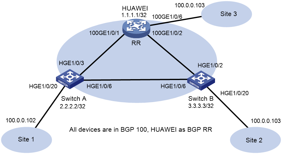
Procedure
· Configure H3C device (Switch A)
# Enable L2VPN.
<SwitchA> system-view
[SwitchA] l2vpn enable
# Set the VXLAN hardware resource mode.
[SwitchA] hardware-resource vxlan border40k
# Disable remote MAC address learning and remote ARP learning.
[SwitchA] vxlan tunnel mac-learning disable
[SwitchA] vxlan tunnel arp-learning disable
# Configure OSPF.
[SwitchA]ospf 1
[SwitchA-ospf-1] area 0
[SwitchA-ospf-1-area-0.0.0.0] quit
[SwitchA-ospf-1] quit
# Configure interface Loopback 0.
[SwitchA] interface LoopBack 0
[SwitchA-LoopBack0] ip address 2.2.2.2 32
[SwitchA-LoopBack0] ospf 1 area 0
[SwitchA-LoopBack0] quit
# Configure the underlay network.
[SwitchA] interface HundredGigE 1/0/3
[SwitchA-HundredGigE1/0/3] ip address 31.1.1.1 255.255.255.0
[SwitchA-HundredGigE1/0/3] ospf 1 area 0.0.0.0
[SwitchA-HundredGigE1/0/3] quit
[SwitchA]interface HundredGigE 1/0/6
[SwitchA-HundredGigE1/0/6] ip address 61.1.1.1 24
[SwitchA-HundredGigE1/0/6] ospf 1 area 0
[SwitchA-HundredGigE1/0/6] quit
# Create VLAN 1001.
[SwitchA] vlan 1001
[SwitchA-vlan1001] quit
# Create an EVPN instance on VSI v1, and configure an RD and RTs for the EVPN instance.
[SwitchA] vsi v1
[SwitchA-vsi-v1] arp suppression enable
[SwitchA-vsi-v1] flooding disable all
[SwitchA-vsi-v1] evpn encapsulation vxlan
[SwitchA-vsi-v1-evpn-vxlan] route-distinguisher 2.2.2.2:10001
[SwitchA-vsi-v1-evpn-vxlan] vpn-target 65001:10001
[SwitchA-vsi-v1-evpn-vxlan] quit
# Create VXLAN 10001.
[SwitchA-vsi-v1] vxlan 10001
[SwitchA-vsi-v1-vxlan-10001] quit
[SwitchA-vsi-v1] quit
# Configure BGP to advertise EVPN routes.
[SwitchA] bgp 100
[SwitchA-bgp-default] peer 1.1.1.1 as-number 100
[SwitchA-bgp-default] peer 1.1.1.1 connect-interface loopback 0
[SwitchA-bgp-default] address-family l2vpn evpn
[SwitchA-bgp-default-evpn] peer 1.1.1.1 enable
[SwitchA-bgp-default-evpn] quit
[SwitchA-bgp-default] quit
# On HundredGigE 1/0/20, create Ethernet service instance 1 to match VLAN 1001.
[SwitchA] interface HundredGigE 1/0/20
[SwitchA-HundredGigE1/0/20] service-instance 1
[SwitchA-HundredGigE1/0/20-srv1000] encapsulation s-vid 1001
# Map Ethernet service instance 1 to VSI v1.
[SwitchA-HundredGigE1/0/20-srv1000] xconnect vsi v1
[SwitchA-HundredGigE1/0/20-srv1000] quit
# Configure RD and RTs for VPN instance vpn1.
[SwitchA] ip vpn-instance vpn1
[SwitchA-vpn-instance-vpn1] route-distinguisher 2.2.2.2:10001
[SwitchA-vpn-instance-vpn1] vpn-target 65001:10001
[SwitchA-vpn-instance-vpn1] address-family evpn
[SwitchA-vpn-evpn-vpn1] vpn-target 65001:10001
[SwitchA-vpn-evpn-vpn1] quit
[SwitchA-vpn-instance-vpn1] quit
# Configure VSI-interface 1.
[SwitchA] interface vsi-interface 1
[SwitchA-Vsi-interface1] ip binding vpn-instance vpn1
[SwitchA-Vsi-interface1] ip address 100.0.0.1 255.255.255.0
[SwitchA-Vsi-interface1] mac-address 0000-2017-0001
[SwitchA-Vsi-interface1] distributed-gateway local
[SwitchA-Vsi-interface1] quit
# Create VSI-interface 16383 and associate it with VPN instance vpn1 and L3VNI 16383.
[SwitchA] interface vsi-interface 16383
[SwitchA-Vsi-interface3] ip binding vpn-instance vpn1
[SwitchA-Vsi-interface3] l3-vni 16383
[SwitchA-Vsi-interface3] quit
# Specify gateway interface VSI-interface 1 for VXLAN 10.
[SwitchA] vsi v1
[SwitchA-vsi-v1] gateway vsi-interface 1
[SwitchA-vsi-v1] quit
· H3C device (Switch B)
# Enable L2VPN.
<SwitchB> system-view
[SwitchB] l2vpn enable
# Set the VXLAN hardware resource mode.
[SwitchB] hardware-resource vxlan border40k
# Disable remote MAC address learning and remote ARP learning.
[SwitchB] vxlan tunnel mac-learning disable
[SwitchB] vxlan tunnel arp-learning disable
# Configure OSPF.
[SwitchB] ospf 1
[SwitchB-ospf-1] area 0
[SwitchB-ospf-1-area-0.0.0.0] quit
[SwitchB-ospf-1] quit
# Configure interface Loopback 0.
[SwitchB] interface LoopBack 0
[SwitchB-LoopBack0] ip address 3.3.3.3 32
[SwitchB-LoopBack0] ospf 1 area 0
[SwitchB-LoopBack0] quit
[SwitchB]
# Configure the underlay network.
[SwitchB] interface HundredGigE 1/0/2
[SwitchB-HundredGigE1/0/2] ip address 21.0.0.1 24
[SwitchB-HundredGigE1/0/2] ospf 1 area 0.0.0.0
[SwitchB-HundredGigE1/0/2] quit
[SwitchB]interface HundredGigE 1/0/6
[SwitchB-HundredGigE1/0/6] ip address 61.1.1.2 24
[SwitchB-HundredGigE1/0/6] ospf 1 area 0.0.0.0
[SwitchB-HundredGigE1/0/6] quit
# Create VLAN 1001.
[SwitchB] vlan 1001
[SwitchB-vlan1001] quit
# Create an EVPN instance on VSI v1, and configure an RD and RTs for the EVPN instance.
[SwitchB] vsi v1
[SwitchB-vsi-v1] arp suppression enable
[SwitchB-vsi-v1] flooding disable all
[SwitchB-vsi-v1] evpn encapsulation vxlan
[SwitchB-vsi-v1-evpn-vxlan] route-distinguisher 3.3.3.3:10001
[SwitchB-vsi-v1-evpn-vxlan] vpn-target 65001:10001
[SwitchB-vsi-v1-evpn-vxlan] quit
# Create VXLAN 10001.
[SwitchB-vsi-v1] vxlan 10001
[SwitchB-vsi-v1-vxlan-10001] quit
[SwitchB-vsi-v1] quit
# Configure BGP to advertise EVPN routes.
[SwitchB] bgp 100
[SwitchB-bgp-default] peer 1.1.1.1 as-number 100
[SwitchB-bgp-default] peer 1.1.1.1 connect-interface loopback 0
[SwitchB-bgp-default] address-family l2vpn evpn
[SwitchB-bgp-default-evpn] peer 1.1.1.1 enable
[SwitchB-bgp-default-evpn] quit
[SwitchB-bgp-default] quit
# On HundredGigE 1/0/20, create Ethernet service instance 1 to match VLAN 1001.
[SwitchB] interface HundredGigE 1/0/20
[SwitchB-HundredGigE1/0/20] service-instance 1
[SwitchB-HundredGigE1/0/20-srv1000] encapsulation s-vid 1001
# Map Ethernet service instance 1 to VSI v1.
[SwitchB-HundredGigE1/0/20-srv1000] xconnect vsi v1
[SwitchB-HundredGigE1/0/20-srv1000] quit
# Configure RD and RTs for VPN instance vpn1.
[SwitchB] ip vpn-instance vpn1
[SwitchB-vpn-instance-vpn1] route-distinguisher 3.3.3.3:10001
[SwitchB-vpn-instance-vpn1] vpn-target 65001:10001
[SwitchB-vpn-instance-vpn1] address-family evpn
[SwitchB-vpn-evpn-vpn1] vpn-target 65001:10001
[SwitchB-vpn-evpn-vpn1] quit
[SwitchB-vpn-instance-vpn1] quit
# Configure VSI-interface 1.
[SwitchB] interface vsi-interface 1
[SwitchB-Vsi-interface1] ip binding vpn-instance vpn1
[SwitchB-Vsi-interface1] ip address 100.0.0.1 24
[SwitchB-Vsi-interface1] mac-address 0000-2017-0001
[SwitchB-Vsi-interface1] distributed-gateway local
[SwitchB-Vsi-interface1] quit
# Create VSI-interface 16383 and associate it with VPN instance vpn1 and L3VNI 16383.
[SwitchB] interface vsi-interface 16383
[SwitchB-Vsi-interface3] ip binding vpn-instance vpn1
[SwitchB-Vsi-interface3] l3-vni 16383
[SwitchB-Vsi-interface3] quit
# Specify gateway interface VSI-interface 1 for VXLAN 10.
[SwitchB] vsi v1
[SwitchB-vsi-v1] gateway vsi-interface 1
[SwitchB-vsi-v1] quit
· Configure the Huawei device
# View device information. Huawei CE6865-48S8CQ-EI is used as an example.
<HUAWEI> display version
Huawei Versatile Routing Platform Software
VRP (R) software, Version 8.191 (CE6865EI V200R019C10SPC800)
Copyright (C) 2012-2020 Huawei Technologies Co., Ltd.
HUAWEI CE6865-48S8CQ-EI uptime is 3 days, 18 hours, 29 minutes
CE6865-48S8CQ-EI(Master) 1 : uptime is 3 days, 18 hours, 28 minutes
StartupTime 2022/06/23 19:58:16
Memory Size : 4096 M bytes
Flash Size : 2048 M bytes
CE6865-48S8CQ-EI version information
1. PCB Version : CEM48S8CQP04 VER A
2. MAB Version : 1
3. Board Type : CE6865-48S8CQ-EI
4. CPLD1 Version : 102
5. CPLD2 Version : 102
6. BIOS Version : 205
# Configure OSPF.
<HUAWEI> sys immediately
Enter system view, return user view with return command.
[HUAWEI] ospf 1
[HUAWEI-ospf-1-area-0.0.0.0] quit
[HUAWEI-ospf-1] quit
# Configure the underlay network.
[HUAWEI] interface 100GE 1/0/1
[HUAWEI-100GE1/0/1] undo portswitch
[HUAWEI-100GE1/0/1] ip address 31.1.1.2 24
[HUAWEI-100GE1/0/1] ospf enable 1 area 0
[HUAWEI-100GE1/0/1] quit
[HUAWEI] interface 100GE 1/0/2
[HUAWEI-100GE1/0/2] undo portswitch
[HUAWEI-100GE1/0/2] ip address 21.1.1.2 24
[HUAWEI-100GE1/0/2] ospf enable 1 area 0
[HUAWEI-100GE1/0/2] quit
# Configure interface Loopback 0.
[HUAWEI]interface LoopBack 0
[HUAWEI-LoopBack0] ip address 1.1.1.1 32
[HUAWEI-LoopBack0] ospf enable 1 area 0
[HUAWEI-LoopBack0] quit
# Enable EVPN as the control plane of VXLAN.
[HUAWEI] evpn-overlay enable
# Configure BGP to advertise EVPN routes.
[HUAWEI] bgp 100
[HUAWEI-bgp] peer 2.2.2.2 as-number 100
[HUAWEI-bgp] peer 2.2.2.2 connect-interface LoopBack 0
[HUAWEI-bgp] peer 3.3.3.3 as-number 100
[HUAWEI-bgp] peer 3.3.3.3 connect-interface LoopBack 0
[HUAWEI-bgp] l2vpn-family evpn
[HUAWEI-bgp-af-evpn] peer 2.2.2.2 enable
Warning: This operation will reset the peer session. Continue? [Y/N]:y
[HUAWEI-bgp-af-evpn] peer 2.2.2.2 reflect-client
[HUAWEI-bgp-af-evpn] peer 3.3.3.3 enable
Warning: This operation will reset the peer session. Continue? [Y/N]:y
[HUAWEI-bgp-af-evpn] peer 3.3.3.3 reflect-client
[HUAWEI-bgp-af-evpn] undo policy vpn-target
[HUAWEI-bgp-af-evpn] quit
[HUAWEI-bgp] quit
# Create VLAN 1001.
[HUAWEI] vlan 1001
[HUAWEI-vlan1001] quit
# Configure service access.
[HUAWEI] bridge-domain 1001
[HUAWEI-bd1001] quit
[HUAWEI] interface 100GE 1/0/6.1 mode l2
[HUAWEI-100GE1/0/6.1] encapsulation dot1q vid 1001
[HUAWEI-100GE1/0/6.1] bridge-domain 1001
[HUAWEI-100GE1/0/6.1] quit
# Configure VPN instance vpn1 and an EVPN instance.
[HUAWEI] ip vpn-instance vpn1
[HUAWEI-vpn-instance-vpn1] vxlan vni 16383
[HUAWEI-vpn-instance-vpn1] ipv4-family
[HUAWEI-vpn-instance-vpn1-af-ipv4] route-distinguisher 1.1.1.1:10001
[HUAWEI-vpn-instance-vpn1-af-ipv4] vpn-target 65001:10001
IVT Assignment result:
Info: VPN-Target assignment is successful.
EVT Assignment result:
Info: VPN-Target assignment is successful.
[HUAWEI-vpn-instance-vpn1-af-ipv4]vpn-target 65001:10001 evpn
IVT Assignment result:
Info: VPN-Target assignment is successful.
EVT Assignment result:
Info: VPN-Target assignment is successful.
[HUAWEI-vpn-instance-vpn1-af-ipv4] quit
[HUAWEI-vpn-instance-vpn1] quit
[HUAWEI] bridge-domain 1001
[HUAWEI-bd1001] vxlan vni 10001
[HUAWEI-bd1001] evpn
[HUAWEI-bd1001-evpn] route-distinguisher 1.1.1.1:10001
[HUAWEI-bd1001-evpn] vpn-target 65001:10001
IVT Assignment result:
Info: VPN-Target assignment is successful.
EVT Assignment result:
Info: VPN-Target assignment is successful.
[HUAWEI-bd1001-evpn] quit
[HUAWEI-bd1001] quit
# Enable head-end replication.
[HUAWEI] int Nve 1
Info: Ensure that the IP addresses and MAC addresses of the NVE interfaces on Devices are the same, as they are dual-active gateways using M-LAG.
[HUAWEI-Nve1] source 1.1.1.1
[HUAWEI-Nve1] vni 10001 head-end peer-list protocol bgp
[HUAWEI-Nve1] quit
# Configure a loopback interface and a Layer 3 VXLAN gateway.
[HUAWEI] int Eth-Trunk 1
[HUAWEI-Eth-Trunk1] service type tunnel
[HUAWEI-Eth-Trunk1] quit
[HUAWEI] int 100 1/0/5
[HUAWEI-100GE1/0/5] eth-trunk 1
[HUAWEI-100GE1/0/5] quit
[HUAWEI] int Vbdif 1001
[HUAWEI-Vbdif10] ip binding vpn-instance vpn1
Info: All IPv4 and IPv6 related configurations on this interface are removed.
[HUAWEI-Vbdif10] ip address 100.0.0.1 24
[HUAWEI-Vbdif10] mac-address 0000-2017-0001
Info: When configuring IP and MAC addresses on a VBDIF interface to implement M-LAG dual-active gateways, you must configure a virtual MAC address.
[HUAWEI-Vbdif10] arp distribute-gateway enable
[HUAWEI-Vbdif10] arp collect host enable
[HUAWEI-Vbdif10] quit
Verifying the configuration
· H3C device (Switch A)
# Verify that BGP L2VPN peers are connected.
[SwitchA] display bgp peer l2vpn evpn
BGP local router ID: 2.2.2.2
Local AS number: 100
Total number of peers: 1 Peers in established state: 1
* - Dynamically created peer
Peer AS MsgRcvd MsgSent OutQ PrefRcv Up/Down State
1.1.1.1 100 3053 2675 0 5 0043h54m Established
# Verify that IPv4 neighbors have been discovered through IMET routes.
[SwitchA] display evpn auto-discovery imet
Total number of automatically discovered peers: 2
VSI name: v1
RD PE_address Tunnel_address Tunnel mode VXLAN ID
1.1.1.1:10001 1.1.1.1 1.1.1.1 VXLAN 10001
3.3.3.3:10001 61.1.1.2 3.3.3.3 VXLAN 10001
# Verify that EVPN routes have been learned for VPN instance vpn1.
[SwitchA] display ip routing-table vpn-instance vpn1
Destinations : 11 Routes : 11
Destination/Mask Proto Pre Cost NextHop Interface
0.0.0.0/32 Direct 0 0 127.0.0.1 InLoop0
100.0.0.0/24 Direct 0 0 100.0.0.1 Vsi1
100.0.0.0/32 Direct 0 0 100.0.0.1 Vsi1
100.0.0.1/32 Direct 0 0 127.0.0.1 InLoop0
100.0.0.102/32 BGP 255 0 3.3.3.3 Vsi16383
100.0.0.255/32 Direct 0 0 100.0.0.1 Vsi1
127.0.0.0/8 Direct 0 0 127.0.0.1 InLoop0
127.0.0.0/32 Direct 0 0 127.0.0.1 InLoop0
127.0.0.1/32 Direct 0 0 127.0.0.1 InLoop0
127.255.255.255/32 Direct 0 0 127.0.0.1 InLoop0
255.255.255.255/32 Direct 0 0 127.0.0.1 InLoop0
# Verify that EVPN routes have been learned for VPN instance vpn1.
[SwitchA] display evpn routing-table vpn-instance vpn1
Flags: E - with valid ESI A - AD ready L - Local ES exists
VPN instance:vpn1 Local L3VNI:16383
IP address Nexthop Outgoing interface NibID Flags
100.0.0.102 3.3.3.3 Vsi-interface16383 0x18000000 -
# Verify that the device has learned EVPN ARP entries.
[SwitchA] display evpn route arp
Flags: D - Dynamic B - BGP L - Local active
G - Gateway S - Static M - Mapping I - Invalid
E - Multihoming ES sync F - Leaf
VPN instance: vpn1 Interface: Vsi-interface1
IP address MAC address Router MAC VSI index Flags
100.0.0.1 0000-2017-0001 78aa-8233-2201 0 GL
100.0.0.101 0010-9400-0001 78aa-8233-2201 0 DL
100.0.0.102 0010-9400-0002 741f-4aa1-2508 0 B
# Verify that the device has learned IPv4 EVPN MAC entries.
[SwitchA] display evpn route mac
Flags: D - Dynamic B - BGP L - Local active
G - Gateway S - Static M - Mapping I - Invalid
E - Multihoming ES sync F - Leaf
VSI name: v1
MAC address : 0010-9400-0001
Link ID/Name : 0x0
Flags : DL
Encap : VXLAN
Next hop : -
Color : -
MAC address : 0000-2017-0001
Link ID/Name : Tunnel1
Flags : BS
Encap : VXLAN
Next hop : 1.1.1.1
Color : -
MAC address : 0010-9400-0002
Link ID/Name : Tunnel0
Flags : B
Encap : VXLAN
Next hop : 3.3.3.3
Color : -
# Verify that the device has established VXLAN tunnels and mapped them to VXLANs.
[SwitchA] display vxlan tunnel
Total number of VXLANs: 2
VXLAN ID: 10001, VSI name: v1, Total tunnels: 2 (2 up, 0 down, 0 defect, 0 blocked)
Tunnel Name Link ID State Type Flood Proxy
Tunnel0 0x50000000 UP Auto Disabled
Tunnel1 0x50000001 UP Auto Disabled
VXLAN ID: 16383, VSI name: Auto_L3VNI16383_16383
# Verify that the device has learned ARP flood suppression entries.
[SwitchA]display arp suppression vsi
IP address MAC address VSI Name Link ID Aging(min)
100.0.0.101 0010-9400-0001 v1 0x0 22
100.0.0.102 0010-9400-0002 v1 0x50000000 N/A
# Verify that VSI information is correct.
[SwitchA] display l2vpn vsi verbose
VSI Name: Auto_L3VNI16383_16383
VSI Index : 16383
VSI State : Down
MTU : 1500
Diffserv Mode : -
Bandwidth : Unlimited
Broadcast Restrain : 4294967295 kbps
Multicast Restrain : 4294967295 kbps
Unknown Unicast Restrain: 4294967295 kbps
MAC Learning : Enabled
MAC Table Limit : -
MAC Learning rate : -
Drop Unknown : -
PW Redundancy Mode : Slave
Flooding : Enabled
Statistics : Disabled
Gateway Interface : VSI-interface 16383
VXLAN ID : 16383
VSI Name: v1
VSI Index : 0
VSI State : Up
MTU : 1500
Diffserv Mode : -
Bandwidth : Unlimited
Broadcast Restrain : 4294967295 kbps
Multicast Restrain : 4294967295 kbps
Unknown Unicast Restrain: 4294967295 kbps
MAC Learning : Enabled
MAC Table Limit : -
MAC Learning rate : -
Drop Unknown : -
PW Redundancy Mode : Slave
Flooding : Disabled
Statistics : Disabled
Gateway Interface : VSI-interface 1
VXLAN ID : 10001
Tunnels:
Tunnel Name Link ID State Type Flood Proxy
Tunnel0 0x50000000 UP Auto Disabled
Tunnel1 0x50000001 UP Auto Disabled
ACs:
AC Link ID State Type
HGE1/0/20 srv1 0x0 Up Manual
Statistics: Disabled
· H3C device (Switch B)
# Verify that BGP L2VPN peers are connected.
[SwitchB] display bgp peer l2vpn evpn
BGP local router ID: 61.1.1.2
Local AS number: 100
Total number of peers: 1 Peers in established state: 1
* - Dynamically created peer
Peer AS MsgRcvd MsgSent OutQ PrefRcv Up/Down State
1.1.1.1 100 3253 3047 0 6 0046h35m Established
# Verify that IPv4 neighbors have been discovered through IMET routes.
[SwitchB] display evpn auto-discovery imet
Total number of automatically discovered peers: 2
VSI name: v1
RD PE_address Tunnel_address Tunnel mode VXLAN ID
1.1.1.1:10001 1.1.1.1 1.1.1.1 VXLAN 10001
2.2.2.2:10001 2.2.2.2 2.2.2.2 VXLAN 10001
# Verify that EVPN routes have been learned for VPN instance vpn1.
[SwitchB] display ip routing-table vpn-instance vpn1
Destinations : 13 Routes : 13
Destination/Mask Proto Pre Cost NextHop Interface
0.0.0.0/32 Direct 0 0 127.0.0.1 InLoop0
100.0.0.0/24 Direct 0 0 100.0.0.1 Vsi1
100.0.0.0/32 Direct 0 0 100.0.0.1 Vsi1
100.0.0.1/32 Direct 0 0 127.0.0.1 InLoop0
100.0.0.101/32 BGP 255 0 2.2.2.2 Vsi16383
100.0.0.255/32 Direct 0 0 100.0.0.1 Vsi1
127.0.0.0/8 Direct 0 0 127.0.0.1 InLoop0
127.0.0.0/32 Direct 0 0 127.0.0.1 InLoop0
127.0.0.1/32 Direct 0 0 127.0.0.1 InLoop0
127.255.255.255/32 Direct 0 0 127.0.0.1 InLoop0
224.0.0.0/4 Direct 0 0 0.0.0.0 NULL0
224.0.0.0/24 Direct 0 0 0.0.0.0 NULL0
255.255.255.255/32 Direct 0 0 127.0.0.1 InLoop0
# Verify that EVPN routes have been learned for VPN instance vpn1.
[SwitchB] display evpn routing-table vpn-instance vpn1
Flags: E - with valid ESI A - AD ready L - Local ES exists
VPN instance:vpn1 Local L3VNI:16383
IP address Nexthop Outgoing interface NibID Flags
100.0.0.101 2.2.2.2 Vsi-interface16383 0x18000000 -
# Verify that the device has learned EVPN ARP entries.
[SwitchB] display evpn route arp
Flags: D - Dynamic B - BGP L - Local active
G - Gateway S - Static M - Mapping I - Invalid
VPN instance: vpn1 Interface: Vsi-interface1
IP address MAC address Router MAC VSI index Flags
100.0.0.1 0000-2017-0001 741f-4aa1-2508 0 GL
100.0.0.101 0010-9400-0001 78aa-8233-2201 0 B
100.0.0.102 0010-9400-0002 741f-4aa1-2508 0 DL
# Verify that the device has learned IPv4 EVPN MAC entries.
[SwitchB] display evpn route mac
Flags: D - Dynamic B - BGP L - Local active
G - Gateway S - Static M - Mapping I - Invalid
VSI name: v1
MAC address Link ID/Name Flags Nexthop
0000-2017-0001 Tunnel1 BS 1.1.1.1
0010-9400-0001 Tunnel0 B 2.2.2.2
# Verify that the device has established VXLAN tunnels and mapped them to VXLANs.
[SwitchB] display vxlan tunnel
Total number of VXLANs: 2
VXLAN ID: 10001, VSI name: v1, Total tunnels: 2 (2 up, 0 down, 0 defect, 0 blocked)
Tunnel name Link ID State Type Flood proxy
Tunnel0 0x5000000 UP Auto Disabled
Tunnel1 0x5000001 UP Auto Disabled
VXLAN ID: 16383, VSI name: Auto_L3VNI16383_16383
# Verify that VSI information is correct.
[SwitchB] display l2vpn vsi verbose
VSI Name: Auto_L3VNI16383_16383
VSI Index : 1
VSI State : Down
MTU : 1500
Bandwidth : Unlimited
Broadcast Restrain : Unlimited
Multicast Restrain : Unlimited
Unknown Unicast Restrain: Unlimited
MAC Learning : Enabled
MAC Table Limit : -
MAC Learning rate : -
Drop Unknown : -
Flooding : Enabled
Statistics : Disabled
Gateway Interface : VSI-interface 16383
VXLAN ID : 16383
VSI Name: v1
VSI Index : 0
VSI State : Up
MTU : 1500
Bandwidth : Unlimited
Broadcast Restrain : Unlimited
Multicast Restrain : Unlimited
Unknown Unicast Restrain: Unlimited
MAC Learning : Enabled
MAC Table Limit : -
MAC Learning rate : -
Drop Unknown : -
Flooding : Disabled
Statistics : Disabled
Gateway Interface : VSI-interface 1
VXLAN ID : 10001
Tunnels:
Tunnel Name Link ID State Type Flood proxy
Tunnel0 0x5000000 UP Auto Disabled
Tunnel1 0x5000001 UP Auto Disabled
ACs:
AC Link ID State Type
HGE1/0/20 srv1 0 Up Manual
· Huawei device
# Verify that the device has established BGP EVPN peer relationships.
[HUAWEI] display bgp evpn peer
Status codes: * - Dynamic
BGP local router ID : 1.1.1.1
Local AS number : 100
Total number of peers : 2
Peers in established state : 2
Total number of dynamic peers : 0
Peer V AS MsgRcvd MsgSent OutQ Up/Down State PrefRcv
2.2.2.2 4 100 2848 3248 0 0046h31m Established 3
3.3.3.3 4 100 3041 3247 0 0046h31m Established 3
# Verify that the EVPN instance configuration is correct.
[HUAWEI] display evpn vpn-instance name 1001
EVPN-Instance Name RD Address-family
1001 1.1.1.1:10001 evpn
# Verify that EVPN routes have been learned for VPN instance vpn1.
[HUAWEI] display ip routing-table vpn-instance vpn1
Proto: Protocol Pre: Preference
Route Flags: R - relay, D - download to fib, T - to vpn-instance, B - black hole route
------------------------------------------------------------------------------
Routing Table : vpn1
Destinations : 6 Routes : 6
Destination/Mask Proto Pre Cost Flags NextHop Interface
100.0.0.0/24 Direct 0 0 D 100.0.0.1 Vbdif1001
100.0.0.1/32 Direct 0 0 D 127.0.0.1 Vbdif1001
100.0.0.101/32 IBGP 255 0 RD 2.2.2.2 VXLAN
100.0.0.102/32 IBGP 255 0 RD 3.3.3.3 VXLAN
100.0.0.255/32 Direct 0 0 D 127.0.0.1 Vbdif1001
255.255.255.255/32 Direct 0 0 D 127.0.0.1 InLoopBack0
# Verify that the device has established VXLAN tunnels and mapped them to VXLANs.
[HUAWEI] display vxlan tunnel
Number of vxlan tunnel : 2
Tunnel ID Source Destination State Type Uptime
-----------------------------------------------------------------------------------
4026531842 1.1.1.1 2.2.2.2 up dynamic 0046h01m
4026531843 1.1.1.1 3.3.3.3 up dynamic 0046h01m
Example: Configuring EBGP for interoperation
Network configuration
As shown in Figure 4, configure the H3C and Huawei devices as follows:
· Configure H3C devices Switch A and Switch B as distributed EVPN gateways.
· Configure the Huawei device as a distributed EVPN gateway.
· Configure EVPN to provide Layer 2 connectivity within the same VXLAN and Layer 3 connectivity among different VXLANs.
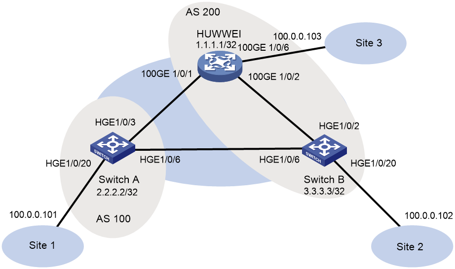
Procedure
· Configure H3C device (Switch A)
# Enable L2VPN.
<SwitchA> system-view
[SwitchA] l2vpn enable
# Set the VXLAN hardware resource mode.
[SwitchA] hardware-resource vxlan border40k
# Disable remote MAC address learning and remote ARP learning.
[SwitchA] vxlan tunnel mac-learning disable
[SwitchA] vxlan tunnel arp-learning disable
# Configure OSPF.
[SwitchA] ospf 1
[SwitchA-ospf-1] area 0
[SwitchA-ospf-1-area-0.0.0.0] quit
[SwitchA-ospf-1] quit
# Configure interface Loopback 0.
[SwitchA] interface LoopBack 0
[SwitchA-LoopBack0] ip address 2.2.2.2 32
[SwitchA-LoopBack0] ospf 1 area 0
[SwitchA-LoopBack0] quit
# Configure the underlay network.
[SwitchA] interface HundredGigE 1/0/3
[SwitchA-HundredGigE1/0/3] ip address 31.1.1.1 255.255.255.0
[SwitchA-HundredGigE1/0/3] ospf 1 area 0.0.0.0
[SwitchA-HundredGigE1/0/3] quit
[SwitchA]interface HundredGigE 1/0/6
[SwitchA-HundredGigE1/0/6] ip address 61.1.1.1 24
[SwitchA-HundredGigE1/0/6] ospf 1 area 0
[SwitchA-HundredGigE1/0/6] quit
# Create VLAN 1001.
[SwitchA] vlan 1001
[SwitchA-vlan1001] quit
# Create an EVPN instance on VSI v1, and configure an RD and RTs for the EVPN instance.
[SwitchA] vsi v1
[SwitchA-vsi-v1] arp suppression enable
[SwitchA-vsi-v1] flooding disable all
[SwitchA-vsi-v1] evpn encapsulation vxlan
[SwitchA-vsi-v1-evpn-vxlan] route-distinguisher 2.2.2.2:10001
[SwitchA-vsi-v1-evpn-vxlan] vpn-target 65001:10001
[SwitchA-vsi-v1-evpn-vxlan] quit
# Create VXLAN 10001.
[SwitchA-vsi-v1] vxlan 10001
[SwitchA-vsi-v1-vxlan-10001] quit
[SwitchA-vsi-v1] quit
# Configure BGP to advertise EVPN routes.
[SwitchA] bgp 100
[SwitchA-bgp-default] peer 1.1.1.1 as-number 200
[SwitchA-bgp-default] peer 1.1.1.1 connect-interface loopback 0
[SwitchA-bgp-default] peer 1.1.1.1 ebgp-max-hop 10
[SwitchA-bgp-default] peer 3.3.3.3 as-number 200
[SwitchA-bgp-default] peer 3.3.3.3 connect-interface loopback 0
[SwitchA-bgp-default] peer 3.3.3.3 ebgp-max-hop 10
[SwitchA-bgp-default] address-family l2vpn evpn
[SwitchA-bgp-default-evpn] peer 1.1.1.1 enable
[SwitchA-bgp-default-evpn] peer 3.3.3.3 enable
[SwitchA-bgp-default-evpn] quit
[SwitchA-bgp-default] quit
# On HundredGigE 1/0/20, create Ethernet service instance 1 to match VLAN 1001.
[SwitchA] interface HundredGigE 1/0/20
[SwitchA-HundredGigE1/0/20] service-instance 1
[SwitchA-HundredGigE1/0/20-srv1000] encapsulation s-vid 1001
# Map Ethernet service instance 1 to VSI v1.
[SwitchA-HundredGigE1/0/20-srv1000] xconnect vsi v1
[SwitchA-HundredGigE1/0/20-srv1000] quit
# Configure RD and RTs for VPN instance vpn1.
[SwitchA] ip vpn-instance vpn1
[SwitchA-vpn-instance-vpn1] route-distinguisher 2.2.2.2:10001
[SwitchA-vpn-instance-vpn1] vpn-target 65001:10001
[SwitchA-vpn-instance-vpn1] address-family evpn
[SwitchA-vpn-evpn-vpn1] vpn-target 65001:10001
[SwitchA-vpn-evpn-vpn1] quit
[SwitchA-vpn-instance-vpn1] quit
# Configure VSI-interface 1.
[SwitchA] interface vsi-interface 1
[SwitchA-Vsi-interface1] ip binding vpn-instance vpn1
[SwitchA-Vsi-interface1] ip address 100.0.0.1 255.255.255.0
[SwitchA-Vsi-interface1] mac-address 0000-2017-0001
[SwitchA-Vsi-interface1] distributed-gateway local
[SwitchA-Vsi-interface1] quit
# Create VSI-interface 16383 and associate it with VPN instance vpn1 and L3VNI 16383.
[SwitchA] interface vsi-interface 16383
[SwitchA-Vsi-interface3] ip binding vpn-instance vpn1
[SwitchA-Vsi-interface3] l3-vni 16383
[SwitchA-Vsi-interface3] quit
# Specify gateway interface VSI-interface 1 for VXLAN 10.
[SwitchA] vsi v1
[SwitchA-vsi-v1] gateway vsi-interface 1
[SwitchA-vsi-v1] quit
· Configure H3C device (Switch B)
# Enable L2VPN.
<SwitchB> system-view
[SwitchB] l2vpn enable
# Set the VXLAN hardware resource mode.
[SwitchB] hardware-resource vxlan border40k
# Disable remote MAC address learning and remote ARP learning.
[SwitchB] vxlan tunnel mac-learning disable
[SwitchB] vxlan tunnel arp-learning disable
# Configure OSPF.
[SwitchB] ospf 1
[SwitchB-ospf-1] area 0
[SwitchB-ospf-1-area-0.0.0.0] quit
[SwitchB-ospf-1] quit
# Configure interface Loopback 0.
[SwitchB] interface LoopBack 0
[SwitchB-LoopBack0] ip address 3.3.3.3 32
[SwitchB-LoopBack0] ospf 1 area 0
[SwitchB-LoopBack0] quit
# Configure the underlay network.
[SwitchB] interface HundredGigE 1/0/2
[SwitchB-HundredGigE1/0/2] ip address 21.0.0.1 24
[SwitchB-HundredGigE1/0/2] ospf 1 area 0.0.0.0
[SwitchB-HundredGigE1/0/2] quit
[SwitchB] interface HundredGigE 1/0/6
[SwitchB-HundredGigE1/0/6] ip address 61.1.1.2 24
[SwitchB-HundredGigE1/0/6] ospf 1 area 0.0.0.0
[SwitchB-HundredGigE1/0/6] quit
# Create VLAN 1001.
[SwitchB] vlan 1001
[SwitchB-vlan1001] quit
# Create an EVPN instance on VSI v1, and configure an RD and RTs for the EVPN instance.
[SwitchB] vsi v1
[SwitchB-vsi-v1] arp suppression enable
[SwitchB-vsi-v1] flooding disable all
[SwitchB-vsi-v1] evpn encapsulation vxlan
[SwitchB-vsi-v1-evpn-vxlan] route-distinguisher 3.3.3.3:10001
[SwitchB-vsi-v1-evpn-vxlan] vpn-target 65001:10001
[SwitchB-vsi-v1-evpn-vxlan] quit
# Create VXLAN 10001.
[SwitchB-vsi-v1] vxlan 10001
[SwitchB-vsi-v1-vxlan-10001] quit
[SwitchB-vsi-v1] quit
# Configure BGP to advertise EVPN routes.
[SwitchB] bgp 200
[SwitchB-bgp-default] peer 1.1.1.1 as-number 200
[SwitchB-bgp-default] peer 1.1.1.1 connect-interface loopback 0
[SwitchB-bgp-default] peer 2.2.2.2 as-number 100
[SwitchB-bgp-default] peer 2.2.2.2 connect-interface loopback 0
[SwitchB-bgp-default] peer 2.2.2.2 ebgp-max-hop 10
[SwitchB-bgp-default] address-family l2vpn evpn
[SwitchB-bgp-default-evpn] peer 1.1.1.1 enable
[SwitchB-bgp-default-evpn] peer 2.2.2.2 enable
[SwitchB-bgp-default-evpn] quit
[SwitchB-bgp-default] quit
# On HundredGigE 1/0/20, create Ethernet service instance 1 to match VLAN 1001.
[SwitchB] interface HundredGigE 1/0/20
[SwitchB-HundredGigE1/0/20] service-instance 1
[SwitchB-HundredGigE1/0/20-srv1000] encapsulation s-vid 1001
# Map Ethernet service instance 1 to VSI v1.
[SwitchB-HundredGigE1/0/20-srv1000] xconnect vsi v1
[SwitchB-HundredGigE1/0/20-srv1000] quit
# Configure RD and RTs for VPN instance vpn1.
[SwitchB] ip vpn-instance vpn1
[SwitchB-vpn-instance-vpn1] route-distinguisher 3.3.3.3:10001
[SwitchB-vpn-instance-vpn1] vpn-target 65001:10001
[SwitchB-vpn-instance-vpn1] address-family evpn
[SwitchB-vpn-evpn-vpn1] vpn-target 65001:10001
[SwitchB-vpn-evpn-vpn1] quit
[SwitchB-vpn-instance-vpn1] quit
# Configure VSI-interface 1.
[SwitchB] interface vsi-interface 1
[SwitchB-Vsi-interface1] ip binding vpn-instance vpn1
[SwitchB-Vsi-interface1] ip address 100.0.0.1 24
[SwitchB-Vsi-interface1] mac-address 0000-2017-0001
[SwitchB-Vsi-interface1] distributed-gateway local
[SwitchB-Vsi-interface1] quit
# Create VSI-interface 16383 and associate it with VPN instance vpn1 and L3VNI 16383.
[SwitchB] interface vsi-interface 16383
[SwitchB-Vsi-interface3] ip binding vpn-instance vpn1
[SwitchB-Vsi-interface3] l3-vni 16383
[SwitchB-Vsi-interface3] quit
# Specify gateway interface VSI-interface 1 for VXLAN 10.
[SwitchB] vsi v1
[SwitchB-vsi-v1] gateway vsi-interface 1
[SwitchB-vsi-v1] quit
· Configure the Huawei device
# View device information. Huawei CE6865-48S8CQ-EI is used as an example.
<HUAWEI> display version
Huawei Versatile Routing Platform Software
VRP (R) software, Version 8.191 (CE6865EI V200R019C10SPC800)
Copyright (C) 2012-2020 Huawei Technologies Co., Ltd.
HUAWEI CE6865-48S8CQ-EI uptime is 3 days, 18 hours, 29 minutes
CE6865-48S8CQ-EI(Master) 1 : uptime is 3 days, 18 hours, 28 minutes
StartupTime 2022/06/23 19:58:16
Memory Size : 4096 M bytes
Flash Size : 2048 M bytes
CE6865-48S8CQ-EI version information
1. PCB Version : CEM48S8CQP04 VER A
2. MAB Version : 1
3. Board Type : CE6865-48S8CQ-EI
4. CPLD1 Version : 102
5. CPLD2 Version : 102
6. BIOS Version : 205
# Configure OSPF.
<HUAWEI>sys immediately
Enter system view, return user view with return command.
[HUAWEI] ospf 1
[HUAWEI-ospf-1-area-0.0.0.0] quit
[HUAWEI-ospf-1] quit
# Configure the underlay network.
[HUAWEI] interface 100GE 1/0/1
[HUAWEI-100GE1/0/1] undo portswitch
[HUAWEI-100GE1/0/1] ip address 31.1.1.2 24
[HUAWEI-100GE1/0/1] ospf enable 1 area 0
[HUAWEI-100GE1/0/1] quit
[HUAWEI] interface 100GE 1/0/2
[HUAWEI-100GE1/0/2] undo portswitch
[HUAWEI-100GE1/0/2] ip address 21.1.1.2 24
[HUAWEI-100GE1/0/2] ospf enable 1 area 0
[HUAWEI-100GE1/0/2] quit
# Configure interface Loopback 0.
[HUAWEI] interface LoopBack 0
[HUAWEI-LoopBack0] ip address 1.1.1.1 32
[HUAWEI-LoopBack0] ospf enable 1 area 0
[HUAWEI-LoopBack0] quit
# Enable EVPN as the control plane of VXLAN.
[HUAWEI] evpn-overlay enable
# Configure BGP to advertise EVPN routes.
[HUAWEI] bgp 200
[HUAWEI-bgp] peer 2.2.2.2 as-number 100
[HUAWEI-bgp] peer 2.2.2.2 connect-interface LoopBack 0
[HUAWEI-bgp] peer 2.2.2.2 ebgp-max-hop 10
[HUAWEI-bgp] peer 3.3.3.3 as-number 200
[HUAWEI-bgp] peer 3.3.3.3 connect-interface LoopBack 0
[HUAWEI-bgp] l2vpn-family evpn
[HUAWEI-bgp-af-evpn] peer 2.2.2.2 enable
Warning: This operation will reset the peer session. Continue? [Y/N]:y
[HUAWEI-bgp-af-evpn] peer 3.3.3.3 enable
Warning: This operation will reset the peer session. Continue? [Y/N]:y
[HUAWEI-bgp-af-evpn] undo policy vpn-target
[HUAWEI-bgp-af-evpn] quit
[HUAWEI-bgp] quit
# Create VLAN 1001.
[HUAWEI] vlan 1001
[HUAWEI-vlan1001] quit
# Configure service access.
[HUAWEI] bridge-domain 1001
[HUAWEI-bd1001] quit
[HUAWEI] interface 100GE 1/0/6.1 mode l2
[HUAWEI-100GE1/0/6.1] encapsulation dot1q vid 1001
[HUAWEI-100GE1/0/6.1] bridge-domain 1001
[HUAWEI-100GE1/0/6.1] quit
# Configure VPN instance vpn1 and an EVPN instance.
[HUAWEI] ip vpn-instance vpn1
[HUAWEI-vpn-instance-vpn1] vxlan vni 16383
[HUAWEI-vpn-instance-vpn1] ipv4-family
[HUAWEI-vpn-instance-vpn1-af-ipv4] route-distinguisher 1.1.1.1:10001
[HUAWEI-vpn-instance-vpn1-af-ipv4] vpn-target 65001:10001
IVT Assignment result:
Info: VPN-Target assignment is successful.
EVT Assignment result:
Info: VPN-Target assignment is successful.
[HUAWEI-vpn-instance-vpn1-af-ipv4]vpn-target 65001:10001 evpn
IVT Assignment result:
Info: VPN-Target assignment is successful.
EVT Assignment result:
Info: VPN-Target assignment is successful.
[HUAWEI-vpn-instance-vpn1-af-ipv4] quit
[HUAWEI-vpn-instance-vpn1] quit
[HUAWEI] bridge-domain 1001
[HUAWEI-bd1001] vxlan vni 10001
[HUAWEI-bd1001] evpn
[HUAWEI-bd1001-evpn] route-distinguisher 1.1.1.1:10001
[HUAWEI-bd1001-evpn] vpn-target 65001:10001
IVT Assignment result:
Info: VPN-Target assignment is successful.
EVT Assignment result:
Info: VPN-Target assignment is successful.
[HUAWEI-bd1001-evpn] quit
[HUAWEI-bd1001] quit
# Enable head-end replication.
[HUAWEI] interface Nve 1
Info: Ensure that the IP addresses and MAC addresses of the NVE interfaces on Devices are the same, as they are dual-active gateways using M-LAG.
[HUAWEI-Nve1] source 1.1.1.1
[HUAWEI-Nve1] vni 10001 head-end peer-list protocol bgp
[HUAWEI-Nve1] quit
# Configure a loopback interface and a Layer 3 VXLAN gateway.
[HUAWEI] interface Eth-Trunk 1
[HUAWEI-Eth-Trunk1] service type tunnel
[HUAWEI-Eth-Trunk1] quit
[HUAWEI]interface 100GE 1/0/5
[HUAWEI-100GE1/0/5] eth-trunk 1
[HUAWEI-100GE1/0/5] quit
[HUAWEI] interface Vbdif 1001
[HUAWEI-Vbdif10] ip binding vpn-instance vpn1
Info: All IPv4 and IPv6 related configurations on this interface are removed.
[HUAWEI-Vbdif10] ip address 100.0.0.1 24
[HUAWEI-Vbdif10] mac-address 0000-2017-0001
Info: When configuring IP and MAC addresses on a VBDIF interface to implement M-LAG dual-active gateways, you must configure a virtual MAC address.
[HUAWEI-Vbdif10] arp distribute-gateway enable
[HUAWEI-Vbdif10] arp collect host enable
[HUAWEI-Vbdif10] quit
Verifying the configuration
· H3C device (Switch A)
# Verify that BGP L2VPN peers are connected.
[SwitchA] display bgp peer l2vpn evpn
BGP local router ID: 2.2.2.2
Local AS number: 100
Total number of peers: 2 Peers in established state: 2
* - Dynamically created peer
Peer AS MsgRcvd MsgSent OutQ PrefRcv Up/Down State
1.1.1.1 200 5 14 0 2 00:00:44 Established
3.3.3.3 200 9 9 0 5 00:00:53 Established
# Verify that IPv4 neighbors have been discovered through IMET routes.
[SwitchA] display evpn auto-discovery imet
Total number of automatically discovered peers: 2
VSI name: v1
RD PE_address Tunnel_address Tunnel mode VXLAN ID
1.1.1.1:10001 1.1.1.1 3.3.3.3 VXLAN 10001
3.3.3.3:10001 61.1.1.2 3.3.3.3 VXLAN 10001
# Verify that EVPN routes have been learned for VPN instance vpn1.
[SwitchA] display ip routing-table vpn-instance vpn1
Destinations : 11 Routes : 11
Destination/Mask Proto Pre Cost NextHop Interface
0.0.0.0/32 Direct 0 0 127.0.0.1 InLoop0
100.0.0.0/24 Direct 0 0 100.0.0.1 Vsi1
100.0.0.0/32 Direct 0 0 100.0.0.1 Vsi1
100.0.0.1/32 Direct 0 0 127.0.0.1 InLoop0
100.0.0.102/32 BGP 255 0 3.3.3.3 Vsi16383
100.0.0.255/32 Direct 0 0 100.0.0.1 Vsi1
127.0.0.0/8 Direct 0 0 127.0.0.1 InLoop0
127.0.0.0/32 Direct 0 0 127.0.0.1 InLoop0
127.0.0.1/32 Direct 0 0 127.0.0.1 InLoop0
127.255.255.255/32 Direct 0 0 127.0.0.1 InLoop0
255.255.255.255/32 Direct 0 0 127.0.0.1 InLoop0
# Verify that EVPN routes have been learned for VPN instance vpn1.
[SwitchA] display evpn routing-table vpn-instance vpn1
Flags: E - with valid ESI A - AD ready L - Local ES exists
VPN instance:vpn1 Local L3VNI:16383
IP address Nexthop Outgoing interface NibID Flags
100.0.0.102 3.3.3.3 Vsi-interface16383 0x18000000 -
# Verify that the device has learned EVPN ARP entries.
[SwitchA] display evpn route arp
Flags: D - Dynamic B - BGP L - Local active
G - Gateway S - Static M - Mapping I - Invalid
E - Multihoming ES sync F - Leaf
VPN instance: vpn1 Interface: Vsi-interface1
IP address MAC address Router MAC VSI index Flags
100.0.0.1 0000-2017-0001 78aa-8233-2201 0 GL
100.0.0.101 0010-9400-0001 78aa-8233-2201 0 DL
100.0.0.102 0010-9400-0002 741f-4aa1-2508 0 B
# Verify that the device has learned IPv4 EVPN MAC entries.
[SwitchA] display evpn route mac
Flags: D - Dynamic B - BGP L - Local active
G - Gateway S - Static M - Mapping I - Invalid
E - Multihoming ES sync F - Leaf
VSI name: v1
MAC address : 0010-9400-0001
Link ID/Name : 0x0
Flags : DL
Encap : VXLAN
Next hop : -
Color : -
MAC address : 0010-9400-0002
Link ID/Name : Tunnel0
Flags : B
Encap : VXLAN
Next hop : 3.3.3.3
Color : -
MAC address : 0000-2017-0001
Link ID/Name : Tunnel0
Flags : BS
Encap : VXLAN
Next hop : 3.3.3.3
Color : -
# Verify that the device has established VXLAN tunnels and mapped them to VXLANs.
[SwitchA] display vxlan tunnel
Total number of VXLANs: 2
VXLAN ID: 10001, VSI name: v1, Total tunnels: 1 (1 up, 0 down, 0 defect, 0 blocked)
Tunnel Name Link ID State Type Flood Proxy
Tunnel0 0x50000000 UP Auto Disabled
VXLAN ID: 16383, VSI name: Auto_L3VNI16383_16383
[SwitchA]dis arp suppression vsi
IP address MAC address VSI Name Link ID Aging(min)
100.0.0.101 0010-9400-0001 v1 0x0 24
100.0.0.102 0010-9400-0002 v1 0x50000000 N/A
# Verify that VSI information is correct.
[SwitchA] display l2vpn vsi verbose
VSI Name: Auto_L3VNI16383_16383
VSI Index : 16383
VSI State : Down
MTU : 1500
Diffserv Mode : -
Bandwidth : Unlimited
Broadcast Restrain : 4294967295 kbps
Multicast Restrain : 4294967295 kbps
Unknown Unicast Restrain: 4294967295 kbps
MAC Learning : Enabled
MAC Table Limit : -
MAC Learning rate : -
Drop Unknown : -
PW Redundancy Mode : Slave
Flooding : Enabled
Statistics : Disabled
Gateway Interface : VSI-interface 16383
VXLAN ID : 16383
VSI Name: v1
VSI Index : 0
VSI State : Up
MTU : 1500
Diffserv Mode : -
Bandwidth : Unlimited
Broadcast Restrain : 4294967295 kbps
Multicast Restrain : 4294967295 kbps
Unknown Unicast Restrain: 4294967295 kbps
MAC Learning : Enabled
MAC Table Limit : -
MAC Learning rate : -
Drop Unknown : -
PW Redundancy Mode : Slave
Flooding : Disabled
Statistics : Disabled
Gateway Interface : VSI-interface 1
VXLAN ID : 10001
Tunnels:
Tunnel Name Link ID State Type Flood Proxy
Tunnel0 0x50000000 UP Auto Disabled
ACs:
AC Link ID State Type
HGE1/0/20 srv1 0x0 Up Manual
Statistics: Disabled
· H3C device (Switch B)
# Verify that BGP L2VPN peers are connected.
[SwitchB] display bgp peer l2vpn evpn
BGP local router ID: 61.1.1.2
Local AS number: 200
Total number of peers: 2 Peers in established state: 2
* - Dynamically created peer
Peer AS MsgRcvd MsgSent OutQ PrefRcv Up/Down State
1.1.1.1 200 27 41 0 2 00:14:58 Established
2.2.2.2 100 20 18 0 3 00:08:48 Established
# Verify that IPv4 neighbors have been discovered through IMET routes.
[SwitchB] display evpn auto-discovery imet
Total number of automatically discovered peers: 2
VSI name: v1
RD PE_address Tunnel_address Tunnel mode VXLAN ID
1.1.1.1:10001 1.1.1.1 1.1.1.1 VXLAN 10001
2.2.2.2:10001 2.2.2.2 2.2.2.2 VXLAN 10001
# Verify that EVPN routes have been learned for VPN instance vpn1.
[SwitchB] display ip routing-table vpn-instance vpn1
Destinations : 13 Routes : 13
Destination/Mask Proto Pre Cost NextHop Interface
0.0.0.0/32 Direct 0 0 127.0.0.1 InLoop0
100.0.0.0/24 Direct 0 0 100.0.0.1 Vsi1
100.0.0.0/32 Direct 0 0 100.0.0.1 Vsi1
100.0.0.1/32 Direct 0 0 127.0.0.1 InLoop0
100.0.0.101/32 BGP 255 0 2.2.2.2 Vsi16383
100.0.0.255/32 Direct 0 0 100.0.0.1 Vsi1
127.0.0.0/8 Direct 0 0 127.0.0.1 InLoop0
127.0.0.0/32 Direct 0 0 127.0.0.1 InLoop0
127.0.0.1/32 Direct 0 0 127.0.0.1 InLoop0
127.255.255.255/32 Direct 0 0 127.0.0.1 InLoop0
224.0.0.0/4 Direct 0 0 0.0.0.0 NULL0
224.0.0.0/24 Direct 0 0 0.0.0.0 NULL0
255.255.255.255/32 Direct 0 0 127.0.0.1 InLoop0
# Verify that EVPN routes have been learned for VPN instance vpn1.
[SwitchB] display evpn routing-table vpn-instance vpn1
Flags: E - with valid ESI A - AD ready L - Local ES exists
VPN instance:vpn1 Local L3VNI:16383
IP address Nexthop Outgoing interface NibID Flags
100.0.0.101 2.2.2.2 Vsi-interface16383 0x18000000 -
[SwitchB]display evpn route arp
Flags: D - Dynamic B - BGP L - Local active
G - Gateway S - Static M - Mapping I - Invalid
VPN instance: vpn1 Interface: Vsi-interface1
IP address MAC address Router MAC VSI index Flags
100.0.0.1 0000-2017-0001 741f-4aa1-2508 0 GL
100.0.0.101 0010-9400-0001 78aa-8233-2201 0 B
100.0.0.102 0010-9400-0002 741f-4aa1-2508 0 DL
# Verify that the device has learned IPv4 EVPN MAC entries.
[SwitchB] display evpn route mac
Flags: D - Dynamic B - BGP L - Local active
G - Gateway S - Static M - Mapping I - Invalid
VSI name: v1
MAC address Link ID/Name Flags Nexthop
0010-9400-0001 Tunnel0 B 2.2.2.2
0000-2017-0001 Tunnel1 BS 1.1.1.1
# Verify that the device has established VXLAN tunnels and mapped them to VXLANs.
[SwitchB] display vxlan tunnel
Total number of VXLANs: 2
VXLAN ID: 10001, VSI name: v1, Total tunnels: 2 (2 up, 0 down, 0 defect, 0 blocked)
Tunnel name Link ID State Type Flood proxy
Tunnel0 0x5000000 UP Auto Disabled
Tunnel1 0x5000001 UP Auto Disabled
VXLAN ID: 16383, VSI name: Auto_L3VNI16383_16383
# Verify that the device has learned ARP flood suppression entries.
[SwitchB] display arp suppression vsi
IP address MAC address Vsi Name Link ID Aging
100.0.0.102 0010-9400-0002 v1 0x0 16
100.0.0.101 0010-9400-0001 v1 0x5000000 N/A
# Verify that VSI information is correct.
[SwitchB] display l2vpn vsi verbose
VSI Name: Auto_L3VNI16383_16383
VSI Index : 1
VSI State : Down
MTU : 1500
Bandwidth : Unlimited
Broadcast Restrain : Unlimited
Multicast Restrain : Unlimited
Unknown Unicast Restrain: Unlimited
MAC Learning : Enabled
MAC Table Limit : -
MAC Learning rate : -
Drop Unknown : -
Flooding : Enabled
Statistics : Disabled
Gateway Interface : VSI-interface 16383
VXLAN ID : 16383
VSI Name: v1
VSI Index : 0
VSI State : Up
MTU : 1500
Bandwidth : Unlimited
Broadcast Restrain : Unlimited
Multicast Restrain : Unlimited
Unknown Unicast Restrain: Unlimited
MAC Learning : Enabled
MAC Table Limit : -
MAC Learning rate : -
Drop Unknown : -
Flooding : Disabled
Statistics : Disabled
Gateway Interface : VSI-interface 1
VXLAN ID : 10001
Tunnels:
Tunnel Name Link ID State Type Flood proxy
Tunnel0 0x5000000 UP Auto Disabled
Tunnel1 0x5000001 UP Auto Disabled
ACs:
AC Link ID State Type
HGE1/0/20 srv1 0 Up Manual
· Huawei device
# Verify that the device has established BGP EVPN peer relationships.
[HUAWEI] display bgp evpn peer
Status codes: * - Dynamic
BGP local router ID : 1.1.1.1
Local AS number : 200
Total number of peers : 2
Peers in established state : 2
Total number of dynamic peers : 0
Peer V AS MsgRcvd MsgSent OutQ Up/Down State PrefRcv
2.2.2.2 4 100 24 12 0 00:06:58 Established 3
3.3.3.3 4 200 38 25 0 00:13:17 Established 6
# Verify that the EVPN instance configuration is correct.
[HUAWEI] display evpn vpn-instance name 1001
EVPN-Instance Name RD Address-family
1001 1.1.1.1:10001 evpn
# Verify that EVPN routes have been learned for VPN instance vpn1.
[HUAWEI] display ip routing-table vpn-instance vpn1
Proto: Protocol Pre: Preference
Route Flags: R - relay, D - download to fib, T - to vpn-instance, B - black hole route
------------------------------------------------------------------------------
Routing Table : vpn1
Destinations : 6 Routes : 6
Destination/Mask Proto Pre Cost Flags NextHop Interface
100.0.0.0/24 Direct 0 0 D 100.0.0.1 Vbdif1001
100.0.0.1/32 Direct 0 0 D 127.0.0.1 Vbdif1001
100.0.0.101/32 EBGP 255 0 RD 2.2.2.2 VXLAN
100.0.0.102/32 IBGP 255 0 RD 3.3.3.3 VXLAN
100.0.0.255/32 Direct 0 0 D 127.0.0.1 Vbdif1001
255.255.255.255/32 Direct 0 0 D 127.0.0.1 InLoopBack0
# Verify that the device has established VXLAN tunnels and mapped them to VXLANs.
[HUAWEI] display vxlan tunnel
Number of vxlan tunnel : 2
Tunnel ID Source Destination State Type Uptime
-----------------------------------------------------------------------------------
4026531845 1.1.1.1 3.3.3.3 up dynamic 00:14:12
4026531846 1.1.1.1 2.2.2.2 up dynamic 00:08:01
Interoperation with Ruijie devices
Interoperability analysis
Table 3 EVPN and VXLAN interoperability analysis
|
H3C |
Ruijie |
Interoperability |
|
Supported |
Supported |
Supported |
Example: Configuring IBGP for interoperation
Network configuration
As shown in Figure 5, configure the H3C and Ruijie devices as follows:
· Configure H3C devices Switch A and Switch B as distributed EVPN gateways.
· Configure the Ruijie device as an RR to reflect BGP routes.
· Configure EVPN to provide Layer 2 connectivity within the same VXLAN and Layer 3 connectivity among different VXLANs.

Procedure
· Configure H3C device (Switch A)
# Enable L2VPN.
<SwitchA> system-view
[SwitchA] l2vpn enable
# Set the VXLAN hardware resource mode.
[SwitchA] hardware-resource vxlan border40k
# Disable remote MAC address learning and remote ARP learning.
[SwitchA] vxlan tunnel mac-learning disable
[SwitchA] vxlan tunnel arp-learning disable
# Configure OSPF.
[SwitchA] ospf 1
[SwitchA-ospf-1] area 0
[SwitchA-ospf-1-area-0.0.0.0] quit
[SwitchA-ospf-1] quit
# Configure interface Loopback 0.
[SwitchA] interface LoopBack 0
[SwitchA-LoopBack0] ip address 2.2.2.2 32
[SwitchA-LoopBack0] ospf 1 area 0
[SwitchA-LoopBack0] quit
# Configure the underlay network.
[SwitchA]interface HundredGigE 1/0/6
[SwitchA-HundredGigE1/0/6] ip address 61.1.1.1 24
[SwitchA-HundredGigE1/0/6] ospf 1 area 0.0.0.0
[SwitchA-HundredGigE1/0/6] quit
[SwitchA]interface HundredGigE 1/0/5
[SwitchA-HundredGigE1/0/5] ip address 51.1.1.1 24
[SwitchA-HundredGigE1/0/5] ospf 1 area 0
[SwitchA-HundredGigE1/0/5] quit
# Create VLAN 1001.
[SwitchA] vlan 1001
[SwitchA-vlan1001] quit
# Create an EVPN instance on VSI v1, and configure an RD and RTs for the EVPN instance.
[SwitchA] vsi v1
[SwitchA-vsi-v1] arp suppression enable
[SwitchA-vsi-v1] flooding disable all
[SwitchA-vsi-v1] evpn encapsulation vxlan
[SwitchA-vsi-v1-evpn-vxlan] route-distinguisher 2.2.2.2:10001
[SwitchA-vsi-v1-evpn-vxlan] vpn-target 65001:10001
[SwitchA-vsi-v1-evpn-vxlan] quit
# Create VXLAN 10001.
[SwitchA-vsi-v1] vxlan 10001
[SwitchA-vsi-v1-vxlan-10001] quit
[SwitchA-vsi-v1] quit
# Configure BGP to advertise EVPN routes.
[SwitchA] bgp 100
[SwitchA-bgp-default] peer 1.1.1.1 as-number 100
[SwitchA-bgp-default] peer 1.1.1.1 connect-interface loopback 0
[SwitchA-bgp-default] address-family l2vpn evpn
[SwitchA-bgp-default-evpn] peer 1.1.1.1 enable
[SwitchA-bgp-default-evpn] quit
[SwitchA-bgp-default] quit
# On HundredGigE 1/0/11, create Ethernet service instance 1 to match VLAN 1001.
[SwitchA] interface HundredGigE 1/0/11
[SwitchA-HundredGigE1/0/11] service-instance 1
[SwitchA-HundredGigE1/0/11-srv1000] encapsulation s-vid 1001
# Map Ethernet service instance 1 to VSI v1.
[SwitchA-HundredGigE1/0/11-srv1000] xconnect vsi v1
[SwitchA-HundredGigE1/0/11-srv1000] quit
# Configure RD and RTs for VPN instance vpn1.
[SwitchA] ip vpn-instance vpn1
[SwitchA-vpn-instance-vpn1] route-distinguisher 2.2.2.2:10001
[SwitchA-vpn-instance-vpn1] vpn-target 65001:10001
[SwitchA-vpn-instance-vpn1] address-family evpn
[SwitchA-vpn-evpn-vpn1] vpn-target 65001:10001
[SwitchA-vpn-evpn-vpn1] quit
[SwitchA-vpn-instance-vpn1] quit
# Configure VSI-interface 1.
[SwitchA] interface vsi-interface 1
[SwitchA-Vsi-interface1] ip binding vpn-instance vpn1
[SwitchA-Vsi-interface1] ip address 100.0.0.1 24
[SwitchA-Vsi-interface1] mac-address 0000-2017-0001
[SwitchA-Vsi-interface1] distributed-gateway local
[SwitchA-Vsi-interface1] quit
# Create VSI-interface 16383 and associate it with VPN instance vpn1 and L3VNI 16383.
[SwitchA] interface vsi-interface 16383
[SwitchA-Vsi-interface3] ip binding vpn-instance vpn1
[SwitchA-Vsi-interface3] l3-vni 16383
[SwitchA-Vsi-interface3] quit
# Specify gateway interface VSI-interface 1 for VXLAN 10.
[SwitchA] vsi v1
[SwitchA-vsi-v1] gateway vsi-interface 1
[SwitchA-vsi-v1] quit
· Configure H3C device (Switch B)
# Enable L2VPN.
<SwitchB> system-view
[SwitchB] l2vpn enable
# Set the VXLAN hardware resource mode.
[SwitchB] hardware-resource vxlan border40k
# Disable remote MAC address learning and remote ARP learning.
[SwitchB] vxlan tunnel mac-learning disable
[SwitchB] vxlan tunnel arp-learning disable
# Configure OSPF.
[SwitchB] ospf 1
[SwitchB-ospf-1] area 0
[SwitchB-ospf-1-area-0.0.0.0] quit
[SwitchB-ospf-1] quit
# Configure interface Loopback 0.
[SwitchB] interface LoopBack 0
[SwitchB-LoopBack0] ip address 3.3.3.3 32
[SwitchB-LoopBack0] ospf 1 area 0
[SwitchB-LoopBack0] quit
# Configure the underlay network.
[SwitchB] interface HundredGigE 1/0/3
[SwitchB-HundredGigE1/0/3] ip address 110.0.0.1 24
[SwitchB-HundredGigE1/0/3] ospf 1 area 0.0.0.0
[SwitchB-HundredGigE1/0/3] quit
[SwitchB] interface HundredGigE 1/0/5
[SwitchB-HundredGigE1/0/5] ip address 51.1.1.2 24
[SwitchB-HundredGigE1/0/5] ospf 1 area 0.0.0.0
[SwitchB-HundredGigE1/0/5] quit
# Create VLAN 1001.
[SwitchB] vlan 1001
[SwitchB-vlan1001] quit
# Create an EVPN instance on VSI v1, and configure an RD and RTs for the EVPN instance.
[SwitchB] vsi v1
[SwitchB-vsi-v1] arp suppression enable
[SwitchB-vsi-v1] flooding disable all
[SwitchB-vsi-v1] evpn encapsulation vxlan
[SwitchB-vsi-v1-evpn-vxlan] route-distinguisher 3.3.3.3:10001
[SwitchB-vsi-v1-evpn-vxlan] vpn-target 65001:10001
[SwitchB-vsi-v1-evpn-vxlan] quit
# Create VXLAN 10001.
[SwitchB-vsi-v1] vxlan 10001
[SwitchB-vsi-v1-vxlan-10001] quit
[SwitchB-vsi-v1] quit
# Configure BGP to advertise EVPN routes.
[SwitchB] bgp 100
[SwitchB-bgp-default] peer 1.1.1.1 as-number 100
[SwitchB-bgp-default] peer 1.1.1.1 connect-interface loopback 0
[SwitchB-bgp-default] address-family l2vpn evpn
[SwitchB-bgp-default-evpn] peer 1.1.1.1 enable
[SwitchB-bgp-default-evpn] quit
[SwitchB-bgp-default] quit
# On HundredGigE 1/0/11, create Ethernet service instance 1 to match VLAN 1001.
[SwitchB]interface HundredGigE 1/0/11
[SwitchB-HundredGigE1/0/11] service-instance 1
[SwitchB-HundredGigE1/0/11-srv1000] encapsulation s-vid 1001
# Map Ethernet service instance 1 to VSI v1.
[SwitchB-HundredGigE1/0/11-srv1000] xconnect vsi v1
[SwitchB-HundredGigE1/0/11-srv1000] quit
# Configure RD and RTs for VPN instance vpn1.
[SwitchB] ip vpn-instance vpn1
[SwitchB-vpn-instance-vpn1] route-distinguisher 3.3.3.3:10001
[SwitchB-vpn-instance-vpn1] vpn-target 65001:10001
[SwitchB-vpn-instance-vpn1] address-family evpn
[SwitchB-vpn-evpn-vpn1] vpn-target 65001:10001
[SwitchB-vpn-evpn-vpn1] quit
[SwitchB-vpn-instance-vpn1] quit
# Configure VSI-interface 1.
[SwitchB] interface vsi-interface 1
[SwitchB-Vsi-interface1] ip binding vpn-instance vpn1
[SwitchB-Vsi-interface1] ip address 100.0.0.1 24
[SwitchB-Vsi-interface1] mac-address 0000-2017-0001
[SwitchB-Vsi-interface1] distributed-gateway local
[SwitchB-Vsi-interface1] quit
# Create VSI-interface 16383 and associate it with VPN instance vpn1 and L3VNI 16383.
[SwitchB] interface vsi-interface 16383
[SwitchB-Vsi-interface3] ip binding vpn-instance vpn1
[SwitchB-Vsi-interface3] l3-vni 16383
[SwitchB-Vsi-interface3] quit
# Specify gateway interface VSI-interface 1 for VXLAN 10.
[SwitchB]vsi v1
[SwitchB-vsi-v1]gateway vsi-interface 1
[SwitchB-vsi-v1]quit
· Configure the Ruijie device
# View device information. Ruijie S6510-48VS8CQ is used as an example.
Ruijie> show version
System description : Ruijie Full 25G Routing Switch(S6510-48VS8CQ) By Ruijie Networks
System start time : 2022-06-10 17:56:53
System uptime : 16:16:51:47
System hardware version : 2.30
System software version : S6500_RGOS 11.0(5)B9P59
System patch number : NA
System serial number : G1QH10Q10637A
System boot version : 1.3.8
Module information:
Slot 0 : RG-S6510-48VS8CQ
Hardware version : 2.30
Boot version : 1.3.8
Software version : S6500_RGOS 11.0(5)B9P59
Serial number : G1QH10Q10637A
# Set the VXLAN hardware resource mode.
Ruijie>enable
Ruijie#configure terminal
Enter configuration commands, one per line. End with CNTL/Z.
Ruijie(config)#switch-mode vxlan slot 0
# Configure the gateway MAC address.
Ruijie(config)#fabric anycast-gateway-mac 0000.2017.0001
# Configure OSPF.
Ruijie(config)#route ospf 1
Ruijie(config-router)#area 0
Ruijie(config-router)#router-id 1.1.1.1
Ruijie(config-router)#exit
# Configure interface Loopback 0.
Ruijie(config)#interface loopback 0
Ruijie(config-if-Loopback 0)#ip address 1.1.1.1 32
Ruijie(config-if-Loopback 0)#ip ospf 1 area 0
Ruijie(config-if-Loopback 0)#exit
# Configure the underlay network.
Ruijie(config)#interface hundredGigabitEthernet 0/49
Ruijie(config-if-HundredGigabitEthernet 0/49)#no switchport
Ruijie(config-if-HundredGigabitEthernet 0/49)#ip address 110.0.0.2 24
Ruijie(config-if-HundredGigabitEthernet 0/49)#ip ospf 1 area 0
Ruijie(config-if-HundredGigabitEthernet 0/49)#exit
Ruijie(config)#interface hundredGigabitEthernet 0/51
Ruijie(config-if-HundredGigabitEthernet 0/51)#no switchport
Ruijie(config-if-HundredGigabitEthernet 0/51)#ip address 61.1.1.2 24
Ruijie(config-if-HundredGigabitEthernet 0/51)#ip ospf 1 area 0
Ruijie(config-if-HundredGigabitEthernet 0/51)#exit
# Configure the device as a VTEP.
Ruijie(config)#vtep
Ruijie(config-vtep)#source loopback 0
Ruijie(config-vtep)#arp suppress enable
Ruijie(config-vtep)#exit
# Create a VRF.
Ruijie(config)#ip vrf vpn1
Ruijie(config-vrf)#rd 1.1.1.1:10001
Ruijie(config-vrf)#route-target both 65001:10001
Ruijie(config-vrf)#exit
# Configure an overlay router interface.
Ruijie(config)#interface overlayrouter 1
Ruijie(config-if-OverlayRouter 1)#ip vrf forwarding vpn1
Ruijie(config-if-OverlayRouter 1)#ip address 100.0.0.1 24
Ruijie(config-if-OverlayRouter 1)#anycast-gateway
Ruijie(config-if-OverlayRouter 1)#route-in-vni
Ruijie(config-if-OverlayRouter 1)#exit
# Create VXLAN 10001.
Ruijie(config)#vxlan 10001
Ruijie(config-vxlan)#extend-vlan 1001
Ruijie(config-vxlan)#router-interface overlayRouter 1
Ruijie(config-vxlan)#arp suppress enable
Ruijie(config-vxlan)#exit
# Configure BGP to advertise EVPN routes.
Ruijie(config)#route bgp 100
Ruijie(config-router)#neighbor 2.2.2.2 remote-as 100
Ruijie(config-router)#neighbor 2.2.2.2 update-source Loopback 0
Ruijie(config-router)#neighbor 3.3.3.3 remote-as 100
Ruijie(config-router)#neighbor 3.3.3.3 update-source Loopback 0
Ruijie(config-router)#address-family l2vpn evpn
Ruijie(config-router-af)#neighbor 2.2.2.2 activate
Ruijie(config-router-af)#neighbor 2.2.2.2 route-reflector-client
Ruijie(config-router-af)#neighbor 3.3.3.3 activate
Ruijie(config-router-af)#neighbor 3.3.3.3 route-reflector-client
Ruijie(config-router-af)#exit
Ruijie(config-router)#exit
# Configure EVPN.
Ruijie(config)#evpn
Ruijie(config-evpn)#vni 10001
Ruijie(config-evpn-vni)#rd 1.1.1.1:10001
Ruijie(config-evpn-vni)#route-target both 65001:10001
Ruijie(config-evpn-vni)#exit
Verifying the configuration
· H3C device (Switch A)
# Verify that BGP L2VPN peers are connected.
[SwitchA] display bgp peer l2vpn evpn
BGP local router ID: 2.2.2.2
Local AS number: 100
Total number of peers: 1 Peers in established state: 1
* - Dynamically created peer
Peer AS MsgRcvd MsgSent OutQ PrefRcv Up/Down State
1.1.1.1 100 116 109 0 8 01:30:19 Established
# Verify that IPv4 neighbors have been discovered through IMET routes.
[SwitchA] display evpn auto-discovery imet
Total number of automatically discovered peers: 2
VSI name: v1
RD PE_address Tunnel_address Tunnel mode VXLAN ID
1.1.1.1:10001 1.1.1.1 1.1.1.1 VXLAN 10001
3.3.3.3:10001 3.3.3.3 3.3.3.3 VXLAN 10001
# Verify that EVPN routes have been learned for VPN instance vpn1.
[SwitchA] display ip routing-table vpn-instance vpn1
Destinations : 7 Routes : 7
Destination/Mask Proto Pre Cost NextHop Interface
0.0.0.0/32 Direct 0 0 127.0.0.1 InLoop0
100.0.0.103/32 BGP 255 0 3.3.3.3 Vsi16383
127.0.0.0/8 Direct 0 0 127.0.0.1 InLoop0
127.0.0.0/32 Direct 0 0 127.0.0.1 InLoop0
127.0.0.1/32 Direct 0 0 127.0.0.1 InLoop0
127.255.255.255/32 Direct 0 0 127.0.0.1 InLoop0
255.255.255.255/32 Direct 0 0 127.0.0.1 InLoop0
# Verify that EVPN routes have been learned for VPN instance vpn1.
[SwitchA] display evpn routing-table vpn-instance vpn1
Flags: E - with valid ESI A - AD ready L - Local ES exists
VPN instance:vpn1 Local L3VNI:16383
IP address Nexthop Outgoing interface NibID Flags
100.0.0.103 3.3.3.3 Vsi-interface16383 0x18000000 -
# Verify that the device has learned EVPN ARP entries.
[SwitchA] display evpn route arp
Flags: D - Dynamic B - BGP L - Local active
G - Gateway S - Static M - Mapping I - Invalid
E - Multihoming ES sync F - Leaf
VPN instance: vpna Interface: Vsi-interface1
IP address MAC address Router MAC VSI index Flags
100.0.0.1 0000-2017-0001 - 3 BGI
100.0.0.101 0010-9400-000e - 3 B
100.0.0.102 0010-9400-000f 743a-2021-ae01 3 DL
100.0.0.103 0010-9400-000d 0000-fc00-0243 3 B
# Verify that the device has learned IPv4 EVPN MAC entries.
[SwitchA] display evpn route mac
Flags: D - Dynamic B - BGP L - Local active
G - Gateway S - Static M - Mapping I - Invalid
E - Multihoming ES sync F - Leaf
VSI name: v1
MAC address : 0010-9400-000f
Link ID/Name : 0x0
Flags : DL
Encap : VXLAN
Next hop : -
Color : -
MAC address : 0010-9400-000e
Link ID/Name : Tunnel1
Flags : B
Encap : VXLAN
Next hop : 1.1.1.1
Color : -
MAC address : 0000-2017-0001
Link ID/Name : -
Flags : BGI
Encap : VXLAN
Next hop : 1.1.1.1
Color : -
MAC address : 0010-9400-000d
Link ID/Name : Tunnel0
Flags : B
Encap : VXLAN
Next hop : 3.3.3.3
Color : -
# Verify that the device has established VXLAN tunnels and mapped them to VXLANs.
[SwitchA] display vxlan tunnel
Total number of VXLANs: 4
VXLAN ID: 10, VSI name: vpna
VXLAN ID: 1000, VSI name: Auto_L3VNI1000_1000
VXLAN ID: 10001, VSI name: v1, Total tunnels: 2 (2 up, 0 down, 0 defect, 0 blocked)
Tunnel Name Link ID State Type Flood Proxy
Tunnel0 0x50000000 UP Auto Disabled
Tunnel1 0x50000001 UP Auto Disabled
VXLAN ID: 16383, VSI name: Auto_L3VNI16383_16383
# Verify that the device has learned ARP flood suppression entries.
[SwitchA] display arp suppression vsi
IP address MAC address VSI Name Link ID Aging(min)
100.0.0.1 0000-2017-0001 v1 0x50000001 N/A
100.0.0.102 0010-9400-000f v1 0x0 20
100.0.0.103 0010-9400-000d v1 0x50000000 N/A
100.0.0.101 0010-9400-000e v1 0x50000001 N/A
# Verify that VSI information is correct.
[SwitchA] display l2vpn vsi verbose
VSI Name: Auto_L3VNI1000_1000
VSI Index : 16383
VSI State : Down
MTU : 1500
Diffserv Mode : -
Bandwidth : Unlimited
Broadcast Restrain : 4294967295 kbps
Multicast Restrain : 4294967295 kbps
Unknown Unicast Restrain: 4294967295 kbps
MAC Learning : Enabled
MAC Table Limit : -
MAC Learning rate : -
Drop Unknown : -
PW Redundancy Mode : Slave
Flooding : Enabled
Statistics : Disabled
Gateway Interface : VSI-interface 1000
VXLAN ID : 1000
VSI Name: v1
VSI Index : 3
VSI State : Up
MTU : 1500
Diffserv Mode : -
Bandwidth : Unlimited
Broadcast Restrain : 4294967295 kbps
Multicast Restrain : 4294967295 kbps
Unknown Unicast Restrain: 4294967295 kbps
MAC Learning : Enabled
MAC Table Limit : -
MAC Learning rate : -
Drop Unknown : -
PW Redundancy Mode : Slave
Flooding : Disabled
Statistics : Disabled
Gateway Interface : VSI-interface 1
VXLAN ID : 10001
Tunnels:
Tunnel Name Link ID State Type Flood Proxy
Tunnel0 0x50000000 UP Auto Disabled
Tunnel1 0x50000001 UP Auto Disabled
ACs:
AC Link ID State Type
HGE1/0/11 srv1 0x0 Up Manual
· Ruijie device
# Verify that the VXLAN configuration is correct.
Ruijie(config)#show vxlan
VXLAN Total Count: 1
VXLAN Capacity : 4000
VXLAN 10001
Symmetric property : FALSE
Router Interface : overlayrouter 1 (anycast)
Extend VLAN : 1001
VTEP Adjacency Count: 2
VTEP Adjacency List :
Interface Source IP Destination IP Type
---------------------- --------------- --------------- -------
OverlayTunnel 6145 1.1.1.1 3.3.3.3 dynamic
OverlayTunnel 6147 1.1.1.1 2.2.2.2 dynamic
Example: Configuring EBGP for interoperation
Network configuration
As shown in Figure 6, configure the H3C and Ruijie devices as follows:
· Configure H3C devices Switch A and Switch B as distributed EVPN gateways.
· Configure the Ruijie device as a distributed EVPN gateway.
· Configure EVPN to provide Layer 2 connectivity within the same VXLAN and Layer 3 connectivity among different VXLANs.

Procedure
· Configure H3C device (Switch A)
# Enable L2VPN.
<SwitchA> system-view
[SwitchA] l2vpn enable
# Set the VXLAN hardware resource mode.
[SwitchA] hardware-resource vxlan border40k
# Disable remote MAC address learning and remote ARP learning.
[SwitchA] vxlan tunnel mac-learning disable
[SwitchA] vxlan tunnel arp-learning disable
# Configure OSPF.
[SwitchA] ospf 1
[SwitchA-ospf-1] area 0
[SwitchA-ospf-1-area-0.0.0.0] quit
[SwitchA-ospf-1] quit
# Configure interface Loopback 0.
[SwitchA] interface LoopBack 0
[SwitchA-LoopBack0] ip address 2.2.2.2 32
[SwitchA-LoopBack0] ospf 1 area 0
[SwitchA-LoopBack0] quit
# Configure the underlay network.
[SwitchA] interface HundredGigE 1/0/6
[SwitchA-HundredGigE1/0/6] ip address 61.1.1.1 24
[SwitchA-HundredGigE1/0/6] ospf 1 area 0.0.0.0
[SwitchA-HundredGigE1/0/6] quit
[SwitchA]interface HundredGigE 0/0/5
[SwitchA-HundredGigE1/0/5] ip address 51.1.1.1 24
[SwitchA-HundredGigE1/0/5] ospf 1 area 0
[SwitchA-HundredGigE1/0/5] quit
# Create VLAN 1001.
[SwitchA] vlan 1001
[SwitchA-vlan1001] quit
# Create an EVPN instance on VSI v1, and configure an RD and RTs for the EVPN instance.
[SwitchA] vsi v1
[SwitchA-vsi-v1] arp suppression enable
[SwitchA-vsi-v1] flooding disable all
[SwitchA-vsi-v1] evpn encapsulation vxlan
[SwitchA-vsi-v1-evpn-vxlan] route-distinguisher 2.2.2.2:10001
[SwitchA-vsi-v1-evpn-vxlan] vpn-target 65001:10001
[SwitchA-vsi-v1-evpn-vxlan] quit
# Create VXLAN 10001.
[SwitchA-vsi-v1] vxlan 10001
[SwitchA-vsi-v1-vxlan-10001] quit
[SwitchA-vsi-v1] quit
# Configure BGP to advertise EVPN routes.
[SwitchA] bgp 100
[SwitchA-bgp-default] peer 1.1.1.1 as-number 200
[SwitchA-bgp-default] peer 1.1.1.1 connect-interface loopback 0
[SwitchA-bgp-default] peer 1.1.1.1 ebgp-max-hop 10
[SwitchA-bgp-default] peer 3.3.3.3 as-number 200
[SwitchA-bgp-default] peer 3.3.3.3 connect-interface loopback 0
[SwitchA-bgp-default] peer 3.3.3.3 ebgp-max-hop 10
[SwitchA-bgp-default] address-family l2vpn evpn
[SwitchA-bgp-default-evpn] peer 1.1.1.1 enable
[SwitchA-bgp-default-evpn] peer 3.3.3.3 enable
[SwitchA-bgp-default-evpn] quit
[SwitchA-bgp-default] quit
# On HundredGigE 1/0/11, create Ethernet service instance 1 to match VLAN 1001.
[SwitchA] interface HundredGigE 1/0/11
[SwitchA-HundredGigE1/0/11] service-instance 1
[SwitchA-HundredGigE1/0/11-srv1000] encapsulation s-vid 1001
# Map Ethernet service instance 1 to VSI v1.
[SwitchA-HundredGigE1/0/11-srv1000] xconnect vsi v1
[SwitchA-HundredGigE1/0/11-srv1000] quit
# Configure RD and RTs for VPN instance vpn1.
[SwitchA] ip vpn-instance vpn1
[SwitchA-vpn-instance-vpn1] route-distinguisher 2.2.2.2:10001
[SwitchA-vpn-instance-vpn1] vpn-target 65001:10001
[SwitchA-vpn-instance-vpn1] address-family evpn
[SwitchA-vpn-evpn-vpn1] vpn-target 65001:10001
[SwitchA-vpn-evpn-vpn1] quit
[SwitchA-vpn-instance-vpn1] quit
# Configure VSI-interface 1.
[SwitchA] interface vsi-interface 1
[SwitchA-Vsi-interface1] ip binding vpn-instance vpn1
[SwitchA-Vsi-interface1] ip address 100.0.0.1 24
[SwitchA-Vsi-interface1] mac-address 0000-2017-0001
[SwitchA-Vsi-interface1] distributed-gateway local
[SwitchA-Vsi-interface1] quit
[SwitchA]
# Create VSI-interface 16383 and associate it with VPN instance vpn1 and L3VNI 16383.
[SwitchA]interface vsi-interface 16383
[SwitchA-Vsi-interface3] ip binding vpn-instance vpn1
[SwitchA-Vsi-interface3] l3-vni 16383
[SwitchA-Vsi-interface3] quit
# Specify gateway interface VSI-interface 1 for VXLAN 10.
[SwitchA] vsi v1
[SwitchA-vsi-v1] gateway vsi-interface 1
[SwitchA-vsi-v1] quit
· Configure H3C device (Switch B)
# Enable L2VPN.
<SwitchB> system-view
[SwitchB] l2vpn enable
# Set the VXLAN hardware resource mode.
[SwitchB] hardware-resource vxlan border40k
# Disable remote MAC address learning and remote ARP learning.
[SwitchB] vxlan tunnel mac-learning disable
[SwitchB] vxlan tunnel arp-learning disable
# Configure OSPF.
[SwitchB] ospf 1
[SwitchB-ospf-1] area 0
[SwitchB-ospf-1-area-0.0.0.0] quit
[SwitchB-ospf-1] quit
# Configure interface Loopback 0.
[SwitchB] interface LoopBack 0
[SwitchB-LoopBack0] ip address 3.3.3.3 32
[SwitchB-LoopBack0] ospf 1 area 0
[SwitchB-LoopBack0] quit
# Configure the underlay network.
[SwitchB] interface HundredGigE 1/0/3
[SwitchB-HundredGigE1/0/3] ip address 110.0.0.1 24
[SwitchB-HundredGigE1/0/3] ospf 1 area 0.0.0.0
[SwitchB-HundredGigE1/0/3] quit
[SwitchB]interface HundredGigE 1/0/5
[SwitchB-HundredGigE1/0/5] ip address 51.1.1.2 24
[SwitchB-HundredGigE1/0/5] ospf 1 area 0.0.0.0
[SwitchB-HundredGigE1/0/5] quit
# Create VLAN 1001.
[SwitchB] vlan 1001
[SwitchB-vlan1001] quit
# Create an EVPN instance on VSI v1, and configure an RD and RTs for the EVPN instance.
[SwitchB] vsi v1
[SwitchB-vsi-v1] arp suppression enable
[SwitchB-vsi-v1] flooding disable all
[SwitchB-vsi-v1] evpn encapsulation vxlan
[SwitchB-vsi-v1-evpn-vxlan] route-distinguisher 3.3.3.3:10001
[SwitchB-vsi-v1-evpn-vxlan] vpn-target 65001:10001
[SwitchB-vsi-v1-evpn-vxlan] quit
# Create VXLAN 10001.
[SwitchB-vsi-v1] vxlan 10001
[SwitchB-vsi-v1-vxlan-10001] quit
[SwitchB-vsi-v1] quit
# Configure BGP to advertise EVPN routes.
[SwitchB] bgp 200
[SwitchB-bgp-default] peer 1.1.1.1 as-number 200
[SwitchB-bgp-default] peer 1.1.1.1 connect-interface loopback 0
[SwitchB-bgp-default] peer 2.2.2.2 connect-interface LoopBack0
[SwitchB-bgp-default] peer 2.2.2.2 ebgp-max-hop 10
[SwitchB-bgp-default] address-family l2vpn evpn
[SwitchB-bgp-default-evpn] peer 1.1.1.1 enable
[SwitchB-bgp-default-evpn] peer 2.2.2.2 enable
[SwitchB-bgp-default-evpn] quit
[SwitchB-bgp-default] quit
# On HundredGigE 1/0/11, create Ethernet service instance 1 to match VLAN 1001.
[SwitchB]interface HundredGigE 1/0/11
[SwitchB-HundredGigE1/0/11] service-instance 1
[SwitchB-HundredGigE1/0/11-srv1000] encapsulation s-vid 1001
# Map Ethernet service instance 1 to VSI v1.
[SwitchB-HundredGigE1/0/11-srv1000] xconnect vsi v1
[SwitchB-HundredGigE1/0/11-srv1000] quit
# Configure RD and RTs for VPN instance vpn1.
[SwitchB]ip vpn-instance vpn1
[SwitchB-vpn-instance-vpn1] route-distinguisher 3.3.3.3:10001
[SwitchB-vpn-instance-vpn1] vpn-target 65001:10001
[SwitchB-vpn-instance-vpn1] address-family evpn
[SwitchB-vpn-evpn-vpn1] vpn-target 65001:10001
[SwitchB-vpn-evpn-vpn1] quit
[SwitchB-vpn-instance-vpn1] quit
# Configure VSI-interface 1.
[SwitchB] interface vsi-interface 1
[SwitchB-Vsi-interface1] ip binding vpn-instance vpn1
[SwitchB-Vsi-interface1] ip address 100.0.0.1 24
[SwitchB-Vsi-interface1] mac-address 0000-2017-0001
[SwitchB-Vsi-interface1] distributed-gateway local
[SwitchB-Vsi-interface1] quit
# Create VSI-interface 16383 and associate it with VPN instance vpn1 and L3VNI 16383.
[SwitchB] interface vsi-interface 16383
[SwitchB-Vsi-interface3] ip binding vpn-instance vpn1
[SwitchB-Vsi-interface3] l3-vni 16383
[SwitchB-Vsi-interface3] quit
# Specify gateway interface VSI-interface 1 for VXLAN 10.
[SwitchB] vsi v1
[SwitchB-vsi-v1] gateway vsi-interface 1
[SwitchB-vsi-v1] quit
· Configure the Ruijie device
# View device information. Ruijie S6510-48VS8CQ is used as an example.
Ruijie> show version
System description : Ruijie Full 25G Routing Switch(S6510-48VS8CQ) By Ruijie Networks
System start time : 2022-06-10 17:56:53
System uptime : 16:16:51:47
System hardware version : 2.30
System software version : S6500_RGOS 11.0(5)B9P59
System patch number : NA
System serial number : G1QH10Q10637A
System boot version : 1.3.8
Module information:
Slot 0 : RG-S6510-48VS8CQ
Hardware version : 2.30
Boot version : 1.3.8
Software version : S6500_RGOS 11.0(5)B9P59
Serial number : G1QH10Q10637A
# Set the VXLAN hardware resource mode.
Ruijie>enable
Ruijie#configure terminal
Enter configuration commands, one per line. End with CNTL/Z.
Ruijie(config)#switch-mode vxlan slot 0
# Configure the gateway MAC address.
Ruijie(config)#fabric anycast-gateway-mac 0000.2017.0001
# Configure OSPF.
Ruijie(config)#route ospf 1
Ruijie(config-router)#area 0
Ruijie(config-router)#router-id 1.1.1.1
Ruijie(config-router)#exit
# Configure interface Loopback 0.
Ruijie(config)#interface loopback 0
Ruijie(config-if-Loopback 0)#ip address 1.1.1.1 32
Ruijie(config-if-Loopback 0)#ip ospf 1 area 0
Ruijie(config-if-Loopback 0)#exit
# Configure the underlay network.
Ruijie(config)#interface hundredGigabitEthernet 0/49
Ruijie(config-if-HundredGigabitEthernet 0/49)#no switchport
Ruijie(config-if-HundredGigabitEthernet 0/49)#ip address 110.0.0.2 24
Ruijie(config-if-HundredGigabitEthernet 0/49)#ip ospf 1 area 0
Ruijie(config-if-HundredGigabitEthernet 0/49)#exit
Ruijie(config)#interface hundredGigabitEthernet 0/51
Ruijie(config-if-HundredGigabitEthernet 0/51)#no switchport
Ruijie(config-if-HundredGigabitEthernet 0/51)#ip address 61.1.1.2 24
Ruijie(config-if-HundredGigabitEthernet 0/51)#ip ospf 1 area 0
Ruijie(config-if-HundredGigabitEthernet 0/51)#exit
# Configure the device as a VTEP.
Ruijie(config)#vtep
Ruijie(config-vtep)#source loopback 0
Ruijie(config-vtep)#arp suppress enable
Ruijie(config-vtep)#exit
# Create a VRF.
Ruijie(config)#ip vrf vpn1
Ruijie(config-vrf)#rd 1.1.1.1:10001
Ruijie(config-vrf)#route-target both 65001:10001
Ruijie(config-vrf)#exit
# Configure an overlay router interface.
Ruijie(config)#interface overlayrouter 1
Ruijie(config-if-OverlayRouter 1)#ip vrf forwarding vpn1
Ruijie(config-if-OverlayRouter 1)#ip address 100.0.0.1 24
Ruijie(config-if-OverlayRouter 1)#anycast-gateway
Ruijie(config-if-OverlayRouter 1)#route-in-vni
Ruijie(config-if-OverlayRouter 1)#exit
# Create VXLAN 10001.
Ruijie(config)#vxlan 10001
Ruijie(config-vxlan)#extend-vlan 1001
Ruijie(config-vxlan)#router-interface overlayRouter 1
Ruijie(config-vxlan)#arp suppress enable
Ruijie(config-vxlan)#exit
# Configure BGP to advertise EVPN routes.
Ruijie(config)#route bgp 200
Ruijie(config-router)#neighbor 2.2.2.2 remote-as 100
Ruijie(config-router)#neighbor 2.2.2.2 ebgp-multihop 10
Ruijie(config-router)#neighbor 2.2.2.2 update-source Loopback 0
Ruijie(config-router)#neighbor 3.3.3.3 remote-as 200
Ruijie(config-router)#neighbor 3.3.3.3 update-source Loopback 0
Ruijie(config-router)#address-family l2vpn evpn
Ruijie(config-router-af)#neighbor 2.2.2.2 activate
Ruijie(config-router-af)#neighbor 3.3.3.3 activate
Ruijie(config-router-af)#exit
Ruijie(config-router)#exit
# Configure EVPN.
Ruijie(config)#evpn
Ruijie(config-evpn)#vni 10001
Ruijie(config-evpn-vni)#rd 1.1.1.1:10001
Ruijie(config-evpn-vni)#route-target both 65001:10001
Ruijie(config-evpn-vni)#exit
Verifying the configuration
· H3C device (Switch A)
# Verify that BGP L2VPN peers are connected.
[SwitchA] display bgp peer l2vpn evpn
BGP local router ID: 2.2.2.2
Local AS number: 100
Total number of peers: 2 Peers in established state: 2
* - Dynamically created peer
Peer AS MsgRcvd MsgSent OutQ PrefRcv Up/Down State
1.1.1.1 200 31 42 0 6 00:18:08 Established
3.3.3.3 200 34 39 0 6 00:18:05 Established
# Verify that IPv4 neighbors have been discovered through IMET routes.
[SwitchA] display evpn auto-discovery imet
Total number of automatically discovered peers: 2
VSI name: v1
RD PE_address Tunnel_address Tunnel mode VXLAN ID
1.1.1.1:10001 1.1.1.1 1.1.1.1 VXLAN 10001
3.3.3.3:10001 3.3.3.3 3.3.3.3 VXLAN 10001
# Verify that EVPN routes have been learned for VPN instance vpn1.
[SwitchA] display ip routing-table vpn-instance vpn1
Destinations : 7 Routes : 7
Destination/Mask Proto Pre Cost NextHop Interface
0.0.0.0/32 Direct 0 0 127.0.0.1 InLoop0
100.0.0.103/32 BGP 255 0 3.3.3.3 Vsi16383
127.0.0.0/8 Direct 0 0 127.0.0.1 InLoop0
127.0.0.0/32 Direct 0 0 127.0.0.1 InLoop0
127.0.0.1/32 Direct 0 0 127.0.0.1 InLoop0
127.255.255.255/32 Direct 0 0 127.0.0.1 InLoop0
255.255.255.255/32 Direct 0 0 127.0.0.1 InLoop0
# Verify that EVPN routes have been learned for VPN instance vpn1.
[SwitchA] display evpn routing-table vpn-instance vpn1
Flags: E - with valid ESI A - AD ready L - Local ES exists
VPN instance:vpn1 Local L3VNI:16383
IP address Nexthop Outgoing interface NibID Flags
100.0.0.103 3.3.3.3 Vsi-interface16383 0x18000000 -
# Verify that the device has learned EVPN ARP entries.
[SwitchA] display evpn route arp
Flags: D - Dynamic B - BGP L - Local active
G - Gateway S - Static M - Mapping I - Invalid
E - Multihoming ES sync F - Leaf
VPN instance: vpna Interface: Vsi-interface1
IP address MAC address Router MAC VSI index Flags
100.0.0.1 0000-2017-0001 - 3 BGI
100.0.0.101 0010-9400-000e - 3 B
100.0.0.102 0010-9400-000f 743a-2021-ae01 3 DL
100.0.0.103 0010-9400-000d 0000-fc00-0243 3 B
# Verify that the device has learned IPv4 EVPN MAC entries.
[SwitchA] display evpn route mac
Flags: D - Dynamic B - BGP L - Local active
G - Gateway S - Static M - Mapping I - Invalid
E - Multihoming ES sync F - Leaf
VSI name: v1
MAC address : 0010-9400-000f
Link ID/Name : 0x0
Flags : DL
Encap : VXLAN
Next hop : -
Color : -
MAC address : 0010-9400-000e
Link ID/Name : Tunnel1
Flags : B
Encap : VXLAN
Next hop : 1.1.1.1
Color : -
MAC address : 0000-2017-0001
Link ID/Name : -
Flags : BGI
Encap : VXLAN
Next hop : 1.1.1.1
Color : -
MAC address : 0010-9400-000d
Link ID/Name : Tunnel0
Flags : B
Encap : VXLAN
Next hop : 3.3.3.3
Color : -
# Verify that the device has established VXLAN tunnels and mapped them to VXLANs.
[SwitchA] display vxlan tunnel
Total number of VXLANs: 4
VXLAN ID: 10, VSI name: vpna
VXLAN ID: 1000, VSI name: Auto_L3VNI1000_1000
VXLAN ID: 10001, VSI name: v1, Total tunnels: 2 (2 up, 0 down, 0 defect, 0 blocked)
Tunnel Name Link ID State Type Flood Proxy
Tunnel0 0x50000000 UP Auto Disabled
Tunnel1 0x50000001 UP Auto Disabled
VXLAN ID: 16383, VSI name: Auto_L3VNI16383_16383
# Verify that the device has learned ARP flood suppression entries.
[SwitchA] display arp suppression vsi
IP address MAC address VSI Name Link ID Aging(min)
100.0.0.102 0010-9400-000f v1 0x0 24
100.0.0.1 0000-2017-0001 v1 0x50000001 N/A
100.0.0.101 0010-9400-000e v1 0x50000001 N/A
100.0.0.103 0010-9400-000d v1 0x50000000 N/A
# Verify that VSI information is correct.
[SwitchA] display l2vpn vsi verbose
VSI Name: Auto_L3VNI16383_16383
VSI Index : 16382
VSI State : Down
MTU : 1500
Diffserv Mode : -
Bandwidth : Unlimited
Broadcast Restrain : 4294967295 kbps
Multicast Restrain : 4294967295 kbps
Unknown Unicast Restrain: 4294967295 kbps
MAC Learning : Enabled
MAC Table Limit : -
MAC Learning rate : -
Drop Unknown : -
PW Redundancy Mode : Slave
Flooding : Enabled
Statistics : Disabled
Gateway Interface : VSI-interface 16383
VXLAN ID : 16383
VSI Name: v1
VSI Index : 3
VSI State : Up
MTU : 1500
Diffserv Mode : -
Bandwidth : Unlimited
Broadcast Restrain : 4294967295 kbps
Multicast Restrain : 4294967295 kbps
Unknown Unicast Restrain: 4294967295 kbps
MAC Learning : Enabled
MAC Table Limit : -
MAC Learning rate : -
Drop Unknown : -
PW Redundancy Mode : Slave
Flooding : Disabled
Statistics : Disabled
Gateway Interface : VSI-interface 1
VXLAN ID : 10001
Tunnels:
Tunnel Name Link ID State Type Flood Proxy
Tunnel0 0x50000000 UP Auto Disabled
Tunnel1 0x50000001 UP Auto Disabled
ACs:
AC Link ID State Type
HGE1/0/11 srv1 0x0 Up Manual
Statistics: Disabled
· Ruijie device
# Verify that the VXLAN configuration is correct.
Ruijie(config)#show vxlan
VXLAN Total Count: 1
VXLAN Capacity : 4000
VXLAN 10001
Symmetric property : FALSE
Router Interface : overlayrouter 1 (anycast)
Extend VLAN : 1001
VTEP Adjacency Count: 2
VTEP Adjacency List :
Interface Source IP Destination IP Type
---------------------- --------------- --------------- -------
OverlayTunnel 6145 1.1.1.1 2.2.2.2 dynamic
OverlayTunnel 6147 1.1.1.1 16.1.105.99 dynamic
MSTP/PVST interoperation guide
Interoperation with Cisco devices
Interoperability analysis
The STP, RSTP, and MSTP protocols supported by H3C are standard protocols defined in IEEE. Among the spanning tree protocols supported by Cisco, MSTP is a standard protocol, and Rapid PVST is a Cisco proprietary protocol.
As shown in Table 4, interoperation between H3C spanning tree protocols and Cisco spanning tree protocols is as follows:
· H3C MSTP can completely interoperate with Cisco MSTP.
To implement interoperation, first make sure the region configuration is the same on the connected H3C switches and Cisco switches. Additionally, you must execute the stp config-digest-snooping command on the H3C switches, and enable digest snooping on each interface connecting to a Cisco switch.
Additionally, on an H3C device, the MSTP BPDU format is legacy in Comware 5 and 802.1s in Comware 7. On a Cisco device, you must execute the spanning-tree mst pre-standard (legacy) command or the no spanning-tree mst pre-standard (802.1s) command to set the MSTP BPDU format to legacy or 802.1s, so that the H3C device and the Cisco device have the same MSTP BPDU format.
· H3C MSTP can partially interoperate with Cisco Rapid PVST.
If an H3C device is connected to a Cisco device through an access port, the H3C device will consider the Cisco device as an IEEE802.1D-capable device and perform spanning tree calculation normally. If an H3C device is connected to a Cisco device through a trunk port, a standard STP-capable H3C device can interoperate with a Rapid PVST-capable Cisco device in VLAN 1. However, in another VLAN, a standard STP-capable device cannot recognize Rapid PVST BPDUs. In this case, physical loops must be blocked on the standard STP-capable device, and the ports in blocking state must be on the standard STP-capable device (H3C) rather than on the Rapid PVST-capable device (Cisco). If you cannot do that, broadcast storms exist in VLANs other than VLAN 1.
Table 4 MSTP/PVST interoperability analysis
|
H3C |
Cisco |
Interoperability |
|
STP mode |
MSTP mode (legacy/802.1s encapsulation) |
Supported in instance 0 |
|
STP mode |
Rapid PVST mode |
Supported when Rapid PVST is not disabled for VLAN 1 on the Cisco device |
|
RSTP mode |
MSTP mode (legacy/802.1s encapsulation) |
Supported in instance 0 |
|
RSTP mode |
Rapid PVST mode |
Supported when Rapid PVST is not disabled for VLAN 1 on the Cisco device |
|
MSTP mode |
MSTP mode (legacy/802.1s encapsulation) |
Supported when the stp config-digest-snooping command is executed on an H3C device |
|
MSTP mode |
Rapid PVST mode |
Supported when Rapid PVST is not disabled for VLAN 1 on the Cisco device |
Network configuration
As shown in Figure 7, an H3C device and a Cisco device are interconnected through two links. Configure MSTP on the H3C device and Cisco device to implement MSTP interoperability.

Procedure
· Configure the H3C device
# Create VLAN-interface 2, and assign an IP address and subnet mask to the interface.
<H3C> system-view
[H3C] vlan 2
[H3C-vlan2] quit
[H3C] interface Vlan-interface 2
[H3C-Vlan-interface2] ip address 16.1.11.55 255.255.255.0
[H3C-Vlan-interface2] quit
# Enable digest snooping on GigabitEthernet 1/0/1.
[H3C] interface gigabitethernet 1/0/1
[H3C-GigabitEthernet1/0/1] stp config-digest-snooping
# Set the link type of GigabitEthernet 1/0/1 to trunk, and assign it to VLAN 2.
[H3C-GigabitEthernet1/0/1] port link-type trunk
[H3C-GigabitEthernet1/0/1] port trunk permit vlan 2
[H3C-GigabitEthernet1/0/1] quit
# Enable digest snooping on GigabitEthernet 1/0/2.
[H3C] interface gigabitethernet 1/0/2
[H3C-GigabitEthernet1/0/2] stp config-digest-snooping
# Set the link type of GigabitEthernet 1/0/2 to trunk, and assign it to VLAN 2.
[H3C-GigabitEthernet1/0/2] port link-type trunk
[H3C-GigabitEthernet1/0/2] port trunk permit vlan 2
[H3C-GigabitEthernet1/0/2] quit
# Enable digest snooping globally.
[H3C] stp global config-digest-snooping
# Enable the spanning tree protocol globally.
[H3C] stp global enable
· Configure the Cisco device
# View information about this device.
This section takes a Cisco Nexus9000 C9236C device as an example.
Cisco# show version
Cisco Nexus Operating System (NX-OS) Software
TAC support: http://www.cisco.com/tac
Copyright (C) 2002-2017, Cisco and/or its affiliates.
All rights reserved.
The copyrights to certain works contained in this software are
owned by other third parties and used and distributed under their own
licenses, such as open source. This software is provided "as is," and unless
otherwise stated, there is no warranty, express or implied, including but not
limited to warranties of merchantability and fitness for a particular purpose.
Certain components of this software are licensed under
the GNU General Public License (GPL) version 2.0 or
GNU General Public License (GPL) version 3.0 or the GNU
Lesser General Public License (LGPL) Version 2.1 or
Lesser General Public License (LGPL) Version 2.0.
A copy of each such license is available at
http://www.opensource.org/licenses/gpl-2.0.php and
http://opensource.org/licenses/gpl-3.0.html and
http://www.opensource.org/licenses/lgpl-2.1.php and
http://www.gnu.org/licenses/old-licenses/library.txt.
Software
BIOS: version 07.56
NXOS: version 7.0(3)I4(6)
BIOS compile time: 06/08/2016
NXOS image file is: bootflash:///nxos.7.0.3.I4.6.bin
NXOS compile time: 3/9/2017 22:00:00 [03/10/2017 07:05:18]
Hardware
cisco Nexus9000 C9236C chassis
Intel(R) Xeon(R) CPU @ 1.80GHz with 16400984 kB of memory.
Processor Board ID FDO20511FC7
Device name: switch
bootflash: 53298520 kB
Kernel uptime is 17 day(s), 20 hour(s), 9 minute(s), 30 second(s)
Last reset
Reason: Unknown
System version: 7.0(3)I4(6)
Service:
plugin
Core Plugin, Ethernet Plugin
Active Package(s):
# Enter VLAN-interface 2 configuration mode, and assign an IP address to it.
Cisco# configure terminal
Cisco(config)# interface vlan 2
Cisco(config-if)#ip address 16.1.11.56 255.255.255.0
Cisco(config-if)#exit
# Set the link type of Ethernet 1/11 to trunk, and assign it to VLAN 2.
Cisco(config)# interface Ethernet 1/11
Cisco(config-if)# switchport mode trunk
Cisco(config-if)# switchport access vlan 2
Cisco(config-if)# switchport trunk allowed vlan 2
Cisco(config-if)# exit
# Set the link type of Ethernet 1/13 to trunk, and assign it to VLAN 2.
Cisco(config-if)# interface Ethernet 1/13
Cisco(config-if)# switchport mode trunk
Cisco(config-if)# switchport access vlan 2
Cisco(config-if)# switchport trunk allowed vlan 2
Cisco(config-if)# end
Verifying the configuration
# On the H3C device, display the brief spanning tree status and statistics.
[H3C] display stp brief
MST ID Port Role TP State Protection
0 GigabitEthernet1/0/1 DESI FORWARDING NONE
0 GigabitEthernet1/0/2 DESI FORWARDING NONE
# On the H3C device, display the brief spanning tree status and statistics of MSTI 0 on GigabitEthernet 1/0/2.
[H3C ] display stp instance 0 interface gigabitethernet 1/0/2
-------[CIST Global Info][Mode MSTP]-------
Bridge ID : 32768.1cab-3496-09f6
Bridge times : Hello 2s MaxAge 20s FwdDelay 15s MaxHops 20
Root ID/ERPC : 32768.1cab-3496-09f6, 0
RegRoot ID/IRPC : 32768.1cab-3496-09f6, 0
RootPort ID : 0.0
BPDU-Protection : Disabled
Bridge Config-
Digest-Snooping : Enabled
TC or TCN received : 2
Time since last TC : 0 days 0h:34m:14s
----[Port391(GigabitEthernet1/0/2)][FORWARDING]----
Port protocol : Enabled
Port role : Designated Port
Port ID : 128.391
Port cost(Legacy) : Config=auto, Active=1
Desg.bridge/port : 32768.1cab-3496-09f6, 128.391
Port edged : Config=disabled, Active=disabled
Point-to-Point : Config=auto, Active=true
Transmit limit : 10 packets/hello-time
TC-Restriction : Disabled
Role-Restriction : Disabled
Protection type : Config=none, Active=none
MST BPDU format : Config=auto, Active=802.1s
Port Config-
Digest-Snooping : Enabled
Rapid transition : False
Num of VLANs mapped : 2
Port times : Hello 2s MaxAge 20s FwdDelay 15s MsgAge 0s RemHops 20
BPDU sent : 1784
TCN: 0, Config: 0, RST: 0, MST: 1784
BPDU received : 0
TCN: 0, Config: 0, RST: 0, MST: 0
# On the H3C device, display the brief spanning tree status and statistics of MSTI 0 on GigabitEthernet 1/0/1.
[H3C] display stp instance 0 interface gigabitethernet 1/0/1
-------[CIST Global Info][Mode MSTP]-------
Bridge ID : 32768.1cab-3496-09f6
Bridge times : Hello 2s MaxAge 20s FwdDelay 15s MaxHops 20
Root ID/ERPC : 32768.1cab-3496-09f6, 0
RegRoot ID/IRPC : 32768.1cab-3496-09f6, 0
RootPort ID : 0.0
BPDU-Protection : Disabled
Bridge Config-
Digest-Snooping : Enabled
TC or TCN received : 2
Time since last TC : 0 days 0h:34m:21s
----[Port381(GigabitEthernet1/0/1)][FORWARDING]----
Port protocol : Enabled
Port role : Designated Port (Boundary)
Port ID : 128.381
Port cost(Legacy) : Config=auto, Active=1
Desg.bridge/port : 32768.1cab-3496-09f6, 128.381
Port edged : Config=disabled, Active=disabled
Point-to-Point : Config=auto, Active=true
Transmit limit : 10 packets/hello-time
TC-Restriction : Disabled
Role-Restriction : Disabled
Protection type : Config=none, Active=none
MST BPDU format : Config=auto, Active=802.1s
Port Config-
Digest-Snooping : Enabled
Rapid transition : False
Num of VLANs mapped : 2
Port times : Hello 2s MaxAge 20s FwdDelay 15s MsgAge 0s RemHops 20
BPDU sent : 1787
TCN: 0, Config: 0, RST: 0, MST: 1787
BPDU received : 2
TCN: 0, Config: 0, RST: 2, MST: 0
Interoperation with Huawei devices
Interoperability analysis
Table 5 MSTP/PVST interoperability analysis
|
H3C |
Huawei |
Interoperability |
|
MSTP mode |
MSTP mode |
Supported |
Network configuration
As shown in Figure 8, an H3C device and a Huawei device are interconnected through two links. Configure MSTP on the H3C device and Huawei device to implement MSTP interoperability.

Procedure
· Configure the H3C device
# Enable the spanning tree protocol globally.
<H3C>system-view
[H3C] stp global enable
# Create VLAN-interface 10, and assign an IP address and subnet mask to the interface.
[H3C] vlan 10
[H3C-vlan10] quit
[H3C]interface Vlan-interface 10
[H3C-Vlan-interface10] ip address 100.0.0.1 255.255.255.0
[H3C-Vlan-interface10] quit
# Enable digest snooping on HundredGigE 1/0/1.
[H3C]interface HundredGigE 1/0/1
[H3C-HundredGigE1/0/1] stp config-digest-snooping
# Set the link type of HundredGigE 1/0/1 to trunk, and assign it to VLAN 10.
[H3C-HundredGigE1/0/1] port link-type trunk
[H3C-HundredGigE1/0/1] port trunk permit vlan 10
[H3C-HundredGigE1/0/1] quit
# Enable digest snooping on HundredGigE 1/0/2.
[H3C]interface HundredGigE 1/0/2
[H3C-HundredGigE1/0/2] stp config-digest-snooping
# Set the link type of HundredGigE 1/0/2 to trunk, and assign it to VLAN 10.
[H3C-HundredGigE1/0/2] port link-type trunk
[H3C-HundredGigE1/0/2] port trunk permit vlan 10
[H3C-HundredGigE1/0/2] quit
# Enable digest snooping globally.
[H3C] stp global config-digest-snooping
· Configure the Huawei device
# View information about this device.
This section takes a Huawei CE6865-48S8CQ-EI device as an example.
<HUAWEI> display version
Huawei Versatile Routing Platform Software
VRP (R) software, Version 8.191 (CE6865EI V200R019C10SPC800)
Copyright (C) 2012-2020 Huawei Technologies Co., Ltd.
HUAWEI CE6865-48S8CQ-EI uptime is 3 days, 18 hours, 29 minutes
CE6865-48S8CQ-EI(Master) 1 : uptime is 3 days, 18 hours, 28 minutes
StartupTime 2022/06/23 19:58:16
Memory Size : 4096 M bytes
Flash Size : 2048 M bytes
CE6865-48S8CQ-EI version information
1. PCB Version : CEM48S8CQP04 VER A
2. MAB Version : 1
3. Board Type : CE6865-48S8CQ-EI
4. CPLD1 Version : 102
5. CPLD2 Version : 102
6. BIOS Version : 205
# Enable STP, RSTP, or MSTP on the device.
<HUAWEI>system-view immediately
Enter system view, return user view with return command.
[HUAWEI]stp enable
# Create VLAN-interface 10, and assign an IP address and subnet mask to the interface.
[HUAWEI]vlan 10
[HUAWEI-vlan10]quit
[HUAWEI]interface vlanif 10
[HUAWEI-Vlanif10]ip address 100.0.0.2 24
[HUAWEI-Vlanif10]quit
# Assign 100GE 1/0/1 to VLAN10.
[HUAWEI]interface 100GE 1/0/1
[HUAWEI-100GE1/0/1]port link-type trunk
[HUAWEI-100GE1/0/1]port trunk allow-pass vlan 10
[HUAWEI-100GE1/0/1]quit
# Assign 100GE 1/0/2 to VLAN10.
[HUAWEI]interface 100GE 1/0/2
[HUAWEI-100GE1/0/2]port link-type trunk
[HUAWEI-100GE1/0/2]port trunk allow-pass vlan 10
[HUAWEI-100GE1/0/2]quit
Verifying the configuration
# On the H3C device, display the brief spanning tree status and statistics.
[H3C] display stp brief
MST ID Port Role STP State Protection
0 HundredGigE1/0/1 DESI FORWARDING NONE
0 HundredGigE1/0/2 DESI FORWARDING NONE
# On the H3C device, display the brief spanning tree status and statistics of MSTI 0 on HundredGigE 1/0/1.
[H3C] display stp instance 0 interface HundredGigE 1/0/1
-------[CIST Global Info][Mode MSTP]-------
Bridge ID : 32768.743a-2021-ae00
Bridge times : Hello 2s MaxAge 20s FwdDelay 15s MaxHops 20
Root ID/ERPC : 32768.743a-2021-ae00, 0
RegRoot ID/IRPC : 32768.743a-2021-ae00, 0
RootPort ID : 0.0
BPDU-Protection : Disabled
Bridge Config-
Digest-Snooping : Enabled
TC or TCN received : 0
Time since last TC : 0 days 0h:41m:50s
----[Port51(HundredGigE1/0/1)][FORWARDING]----
Port protocol : Enabled
Port role : Designated Port (Boundary)
Port ID : 128.51
Port cost(Legacy) : Config=auto, Active=1
Desg.bridge/port : 32768.743a-2021-ae00, 128.51
Port edged : Config=disabled, Active=disabled
Point-to-Point : Config=auto, Active=true
Transmit limit : 10 packets/hello-time
TC-Restriction : Disabled
Role-Restriction : Disabled
Protection type : Config=none, Active=none
MST BPDU format : Config=auto, Active=802.1s
Port Config-
Digest-Snooping : Enabled
Rapid transition : True
Num of VLANs mapped : 2
Port times : Hello 2s MaxAge 20s FwdDelay 15s MsgAge 0s RemHops 20
BPDU sent : 1256
TCN: 0, Config: 0, RST: 0, MST: 1256
BPDU received : 3
TCN: 0, Config: 0, RST: 0, MST: 3
Interoperation with Ruijie devices
Interoperability analysis
Table 6 MSTP/PVST interoperability analysis
|
H3C |
Ruijie |
Interoperability |
|
MSTP mode |
MSTP mode |
Supported |
Network configuration
As shown in Figure 9, an H3C device and a Ruijie device are interconnected through two links. Configure MSTP on the H3C device and Ruijie device to implement interoperability.

Procedure
· Configure the H3C device
# Enable the spanning tree protocol globally.
<H3C> system-view
[H3C] stp global enable
# Create VLAN-interface 10, and assign an IP address and subnet mask to the interface.
[H3C] vlan 10
[H3C-vlan10] quit
[H3C] interface Vlan-interface 10
[H3C-Vlan-interface10] ip address 100.0.0.1 24
[H3C-Vlan-interface10] quit
# Set the link type of HundredGigE 1/0/3 to trunk, and assign it to VLAN 10.
[H3C] interface HundredGigE 1/0/3
[H3C-HundredGigE1/0/3] port link-type trunk
[H3C-HundredGigE1/0/3] port trunk permit vlan 10
# Enable digest snooping on HundredGigE 1/0/3.
[H3C-HundredGigE1/0/3] stp config-digest-snooping
[H3C-HundredGigE1/0/3] quit
# Set the link type of HundredGigE 1/0/4 to trunk, and assign it to VLAN 10.
[H3C]interface HundredGigE 1/0/4
[H3C-HundredGigE1/0/4] port link-type trunk
[H3C-HundredGigE1/0/4] port trunk permit vlan 10
# Enable digest snooping on HundredGigE 1/0/4.
[H3C-HundredGigE1/0/4] stp config-digest-snooping
[H3C-HundredGigE1/0/4] quit
# Enable digest snooping globally.
[H3C] stp global config-digest-snooping
· Configure the Ruijie device
# View information about this device.
This section takes a Ruijie S6510-48VS8CQ device as an example.
Ruijie>show version
System description : Ruijie Full 25G Routing Switch(S6510-48VS8CQ) By Ruijie Networks
System start time : 2022-06-10 17:56:53
System uptime : 16:16:51:47
System hardware version : 2.30
System software version : S6500_RGOS 11.0(5)B9P59
System patch number : NA
System serial number : G1QH10Q10637A
System boot version : 1.3.8
Module information:
Slot 0 : RG-S6510-48VS8CQ
Hardware version : 2.30
Boot version : 1.3.8
Software version : S6500_RGOS 11.0(5)B9P59
Serial number : G1QH10Q10637A
# Enable the spanning tree protocol.
Ruijie>enable
Ruijie#configure terminal
Enter configuration commands, one per line. End with CNTL/Z.
Ruijie(config)#spanning-tree
# Assign an IP address to VLAN-interface 10.
Ruijie(config)#interface vlan 10
Ruijie(config-if-VLAN 10)#ip address 100.0.0.2 24
Ruijie(config-if-VLAN 10)#no shutdown
Ruijie(config-if-VLAN 10)#exit
# Set the link type of HundredGigabitEthernet 0/49 to trunk, and assign it to VLAN 10.
Ruijie(config)#interface hundredGigabitEthernet 0/49
Ruijie(config-if-HundredGigabitEthernet 0/49)#switchport
Ruijie(config-if-HundredGigabitEthernet 0/49)#switchport mode trunk
Ruijie(config-if-HundredGigabitEthernet 0/49)#switchport trunk allowed vlan only 10
Ruijie(config-if-HundredGigabitEthernet 0/49)#no shutdown
Ruijie(config-if-HundredGigabitEthernet 0/49)#exit
# Set the link type of HundredGigabitEthernet 0/50 to trunk, and assign it to VLAN 10.
Ruijie(config)#interface hundredGigabitEthernet 0/50
Ruijie(config-if-HundredGigabitEthernet 0/50)#switchport
Ruijie(config-if-HundredGigabitEthernet 0/50)#switchport mode trunk
Ruijie(config-if-HundredGigabitEthernet 0/50)#switchport trunk allowed vlan only 10
Ruijie(config-if-HundredGigabitEthernet 0/50)#no shutdown
Ruijie(config-if-HundredGigabitEthernet 0/50)#exit
Verifying the configuration
# On the H3C device, display the brief spanning tree status and statistics.
[H3C] display stp brief
MST ID Port Role STP State Protection
0 HundredGigE1/0/3 DESI FORWARDING NONE
0 HundredGigE1/0/4 DESI FORWARDING NONE
# On the H3C device, display the brief spanning tree status and statistics of MSTI 0 on HundredGigE 1/0/3.
[H3C] display stp instance 0 interface HundredGigE 1/0/3
-------[CIST Global Info][Mode MSTP]-------
Bridge ID : 32768.0000-fc00-0242
Bridge times : Hello 2s MaxAge 20s FwdDelay 15s MaxHops 20
Root ID/ERPC : 32768.0000-fc00-0242, 0
RegRoot ID/IRPC : 32768.0000-fc00-0242, 0
RootPort ID : 0.0
BPDU-Protection : Disabled
Bridge Config-
Digest-Snooping : Disabled
TC or TCN received : 0
Time since last TC : 0 days 0h:7m:27s
----[Port5(HundredGigE1/0/3)][FORWARDING]----
Port protocol : Enabled
Port role : Designated Port (Boundary)
Port ID : 128.5
Port cost(Legacy) : Config=auto, Active=1
Desg.bridge/port : 32768.0000-fc00-0242, 128.5
Port edged : Config=disabled, Active=disabled
Point-to-Point : Config=auto, Active=true
Transmit limit : 10 packets/hello-time
TC-Restriction : Disabled
Role-Restriction : Disabled
Protection type : Config=none, Active=none
MST BPDU format : Config=auto, Active=802.1s
Port Config-
Digest-Snooping : Enabled
Rapid transition : True
Num of VLANs mapped : 2
Port times : Hello 2s MaxAge 20s FwdDelay 15s MsgAge 0s RemHops 20
BPDU sent : 240
TCN: 0, Config: 0, RST: 0, MST: 240
BPDU received : 1
TCN: 0, Config: 0, RST: 0, MST: 1
LACP link aggregation interoperation guide
Interoperation with Cisco devices
Interoperability analysis
Table 7 Interoperability analysis
|
H3C |
Cisco |
Interoperability |
|
Static (default) |
On (default) |
Supported |
|
Dynamic |
Active |
Supported |
Example: Configuring static link aggregation for interoperation
Network configuration
As shown in Figure 10, an H3C device and a Cisco device are interconnected through their Layer 2 Ethernet interfaces. Configure static link aggregation on the H3C device and Cisco device to increase the link bandwidth and improve link reliability.

Procedure
· Configure the H3C device
# Create Layer 3 aggregate interface 1, and assign an IP address and subnet mask to the interface.
<H3C> system-view
[H3C] interface Route-aggregation 1
[H3C-Route-Aggregation1] ip address 16.1.105.33 24
[H3C-Route-Aggregation1] quit
# Assign Layer 3 Ethernet interface GigabitEthernet 1/0/1 to Layer 3 aggregation group 1.
[H3C] interface gigabitethernet 1/0/1
[H3C-GigabitEthernet1/0/1] port link-aggregation group 1
[H3C-GigabitEthernet1/0/1] quit
# Assign Layer 3 Ethernet interface GigabitEthernet 1/0/2 to Layer 3 aggregation group 1.
[H3C] interface GigabitEthernet 1/0/2
[H3C-GigabitEthernet1/0/2] port link-aggregation group 1
[H3C-GigabitEthernet1/0/2] quit
· Configure the Cisco device
# View information about this device.
This section takes a Cisco Nexus9000 C9236C device as an example.
Cisco# show version
Cisco Nexus Operating System (NX-OS) Software
TAC support: http://www.cisco.com/tac
Copyright (C) 2002-2017, Cisco and/or its affiliates.
All rights reserved.
The copyrights to certain works contained in this software are
owned by other third parties and used and distributed under their own
licenses, such as open source. This software is provided "as is," and unless
otherwise stated, there is no warranty, express or implied, including but not
limited to warranties of merchantability and fitness for a particular purpose.
Certain components of this software are licensed under
the GNU General Public License (GPL) version 2.0 or
GNU General Public License (GPL) version 3.0 or the GNU
Lesser General Public License (LGPL) Version 2.1 or
Lesser General Public License (LGPL) Version 2.0.
A copy of each such license is available at
http://www.opensource.org/licenses/gpl-2.0.php and
http://opensource.org/licenses/gpl-3.0.html and
http://www.opensource.org/licenses/lgpl-2.1.php and
http://www.gnu.org/licenses/old-licenses/library.txt.
Software
BIOS: version 07.56
NXOS: version 7.0(3)I4(6)
BIOS compile time: 06/08/2016
NXOS image file is: bootflash:///nxos.7.0.3.I4.6.bin
NXOS compile time: 3/9/2017 22:00:00 [03/10/2017 07:05:18]
Hardware
cisco Nexus9000 C9236C chassis
Intel(R) Xeon(R) CPU @ 1.80GHz with 16400984 kB of memory.
Processor Board ID FDO20511FC7
Device name: switch
bootflash: 53298520 kB
Kernel uptime is 17 day(s), 20 hour(s), 9 minute(s), 30 second(s)
Last reset
Reason: Unknown
System version: 7.0(3)I4(6)
Service:
plugin
Core Plugin, Ethernet Plugin
Active Package(s):
# Assign an IP addresses to a port channel (aggregate interface).
Cisco# configure terminal
Cisco(config)# interface channel-group 1
Cisco(config-if)# ip address 16.1.105.34 255.255.255.0
Cisco(config-if)# exit
# Set the aggregation mode to manual (static) for Ethernet 1/3.
Cisco(config)# interface Ethernet 1/3
Cisco(config-if)# channel-group 1 mode on
Cisco(config-if)# exit
# Set the aggregation mode to manual (static) for Ethernet 1/5.
Cisco(config-if)# interface Ethernet 1/5
Cisco(config-if)# channel-group 1 mode on
Cisco(config-if)# end
Verifying the configuration
# On the H3C device, display aggregation group details.
[H3C] display link-aggregation verbose
Loadsharing Type: Shar -- Loadsharing, NonS -- Non-Loadsharing
Port Status: S -- Selected, U -- Unselected, I -- Individual
Port: A -- Auto port, M -- Management port, R -- Reference port
Flags: A -- LACP_Activity, B -- LACP_Timeout, C -- Aggregation,
D -- Synchronization, E -- Collecting, F -- Distributing,
G -- Defaulted, H -- Expired
Aggregate Interface: Route-Aggregation1
Aggregation Mode: Static
Loadsharing Type: Shar
Management VLANs: None
Port Status Priority Oper-Key
GE1/0/1(R) S 32768 1
GE1/0/2 S 32768 1
# On the H3C device, verify that you can successfully ping the remote device.
[H3C ] ping 16.1.105.34
Ping 16.1.105.34 (16.1.105.34): 56 data bytes, press CTRL_C to break
56 bytes from 16.1.105.34: icmp_seq=0 ttl=255 time=2.537 ms
56 bytes from 16.1.105.34: icmp_seq=1 ttl=255 time=2.000 ms
56 bytes from 16.1.105.34: icmp_seq=2 ttl=255 time=1.935 ms
56 bytes from 16.1.105.34: icmp_seq=3 ttl=255 time=2.044 ms
56 bytes from 16.1.105.34: icmp_seq=4 ttl=255 time=2.143 ms
--- Ping statistics for 16.1.105.34 ---
5 packet(s) transmitted, 5 packet(s) received, 0.0% packet loss
round-trip min/avg/max/std-dev = 1.935/2.132/2.537/0.214 ms
Example: Configuring dynamic link aggregation for interoperation
Network configuration
As shown in Figure 11, an H3C device and a Cisco device are interconnected through their Layer 2 Ethernet interfaces. Configure dynamic link aggregation on the H3C device and Cisco device to increase the link bandwidth and improve link reliability.

Procedure
· Configure the H3C device
# Create Layer 3 aggregate interface 1, and assign an IP address and subnet mask to the interface.
<H3C> system-view
[H3C] interface Route-aggregation 1
[H3C-Route-Aggregation1] ip address 16.1.105.33 24
# Configure Layer 3 aggregate interface 1 to operate in dynamic aggregation mode.
[H3C-Route-Aggregation1] link-aggregation mode dynamic
[H3C-Route-Aggregation1] quit
# Assign Layer 3 Ethernet interface GigabitEthernet 1/0/1 to Layer 3 aggregation group 1.
[H3C] interface gigabitethernet 1/0/1
[H3C-GigabitEthernet1/0/1] port link-aggregation group 1
[H3C-GigabitEthernet1/0/1] quit
# Assign Layer 3 Ethernet interface GigabitEthernet 1/0/2 to Layer 3 aggregation group 1.
[H3C] interface gigabitethernet 1/0/2
[H3C-GigabitEthernet1/0/2] port link-aggregation group 1
[H3C-GigabitEthernet1/0/2] quit
· Configure the Cisco device
# View information about this device.
This section takes a Cisco Nexus9000 C9236C device as an example.
Cisco# show version
Cisco Nexus Operating System (NX-OS) Software
TAC support: http://www.cisco.com/tac
Copyright (C) 2002-2017, Cisco and/or its affiliates.
All rights reserved.
The copyrights to certain works contained in this software are
owned by other third parties and used and distributed under their own
licenses, such as open source. This software is provided "as is," and unless
otherwise stated, there is no warranty, express or implied, including but not
limited to warranties of merchantability and fitness for a particular purpose.
Certain components of this software are licensed under
the GNU General Public License (GPL) version 2.0 or
GNU General Public License (GPL) version 3.0 or the GNU
Lesser General Public License (LGPL) Version 2.1 or
Lesser General Public License (LGPL) Version 2.0.
A copy of each such license is available at
http://www.opensource.org/licenses/gpl-2.0.php and
http://opensource.org/licenses/gpl-3.0.html and
http://www.opensource.org/licenses/lgpl-2.1.php and
http://www.gnu.org/licenses/old-licenses/library.txt.
Software
BIOS: version 07.56
NXOS: version 7.0(3)I4(6)
BIOS compile time: 06/08/2016
NXOS image file is: bootflash:///nxos.7.0.3.I4.6.bin
NXOS compile time: 3/9/2017 22:00:00 [03/10/2017 07:05:18]
Hardware
cisco Nexus9000 C9236C chassis
Intel(R) Xeon(R) CPU @ 1.80GHz with 16400984 kB of memory.
Processor Board ID FDO20511FC7
Device name: switch
bootflash: 53298520 kB
Kernel uptime is 17 day(s), 20 hour(s), 9 minute(s), 30 second(s)
Last reset
Reason: Unknown
System version: 7.0(3)I4(6)
Service:
plugin
Core Plugin, Ethernet Plugin
Active Package(s):
# Enable LACP.
Cisco# configure terminal
Cisco(config)# feature lacp
# Assign an IP addresses to a port channel (aggregate interface).
Cisco(config)# interface channel-group 1
Cisco(config-if)# ip address 16.1.105.34 255.255.255.0
Cisco(config-if)# exit
# Set the LACP mode to active on Ethernet 1/3.
Cisco(config)# interface Ethernet 1/3
Cisco(config-if)# channel-group 1 mode active
Cisco(config-if)# exit
# Set the LACP mode to active on Ethernet 1/5.
Cisco(config-if)# interface Ethernet 1/5
Cisco(config-if)# channel-group 1 mode active
Cisco(config-if)# end
Verifying the configuration
# On the H3C device, display aggregation group details.
[H3C] display link-aggregation verbose
Loadsharing Type: Shar -- Loadsharing, NonS -- Non-Loadsharing
Port Status: S -- Selected, U -- Unselected, I -- Individual
Port: A -- Auto port, M -- Management port, R -- Reference port
Flags: A -- LACP_Activity, B -- LACP_Timeout, C -- Aggregation,
D -- Synchronization, E -- Collecting, F -- Distributing,
G -- Defaulted, H -- Expired
Aggregate Interface: Route-Aggregation1
Aggregation Mode: Dynamic
Loadsharing Type: Shar
Management VLANs: None
System ID: 0x8000, 1cab-3496-09f6
Local:
Port Status Priority Index Oper-Key Flag
GE1/0/1(R) S 32768 1 1 {ACDEF}
GE1/0/2 S 32768 2 1 {ACDEF}
Remote:
Actor Priority Index Oper-Key SystemID Flag
GE1/0/1 32768 265 32768 0x8000, 2c33-113a-eaef {ACDEF}
GE1/0/2 32768 273 32768 0x8000, 2c33-113a-eaef {ACDEF}
# On the H3C device, verify that you can successfully ping the remote device.
[H3C] ping 16.1.105.34
Ping 16.1.105.34 (16.1.105.34): 56 data bytes, press CTRL_C to break
Request time out
56 bytes from 16.1.105.34: icmp_seq=1 ttl=255 time=2.331 ms
56 bytes from 16.1.105.34: icmp_seq=2 ttl=255 time=2.063 ms
56 bytes from 16.1.105.34: icmp_seq=3 ttl=255 time=2.202 ms
56 bytes from 16.1.105.34: icmp_seq=4 ttl=255 time=2.219 ms
--- Ping statistics for 16.1.105.34 ---
5 packet(s) transmitted, 4 packet(s) received, 20.0% packet loss
round-trip min/avg/max/std-dev = 2.063/2.204/2.331/0.095 ms
Interoperation with Huawei devices
Interoperability analysis
Table 8 Interoperability analysis
|
H3C |
Huawei |
Interoperability |
|
Static (default) |
Normal |
Supported |
|
Dynamic |
Lacp-Static/lacp-Dynamic |
Supported |
Example: Configuring static link aggregation for interoperation
Network configuration
As shown in Figure 12, an H3C device and a Huawei device are interconnected through their Layer 2 Ethernet interfaces. Configure static link aggregation on the H3C device and Huawei device to increase the link bandwidth and improve link reliability.

Procedure
· Configure the H3C device
# Create Layer 3 aggregate interface 1, and assign an IP address and subnet mask to the interface.
<H3C> system-view
[H3C] interface Route-aggregation 1
[H3C-Route-Aggregation1] ip address 100.0.0.1 24
[H3C-Route-Aggregation1] quit
# Assign Layer 3 Ethernet interface HundredGigE 1/0/1 to Layer 3 aggregation group 1.
[H3C] interface HundredGigE 1/0/1
[H3C-HundredGigE1/0/1] port link-aggregation group 1
[H3C-HundredGigE1/0/1] quit
# Assign Layer 3 Ethernet interface HundredGigE 1/0/2 to Layer 3 aggregation group 1.
[H3C] interface HundredGigE 1/0/2
[H3C-HundredGigE1/0/2] port link-aggregation group 1
[H3C-HundredGigE1/0/2] quit
· Configure the Huawei device
# View information about this device.
This section takes a Huawei CE6865-48S8CQ-EI device as an example.
<HUAWEI> display version
Huawei Versatile Routing Platform Software
VRP (R) software, Version 8.191 (CE6865EI V200R019C10SPC800)
Copyright (C) 2012-2020 Huawei Technologies Co., Ltd.
HUAWEI CE6865-48S8CQ-EI uptime is 3 days, 18 hours, 29 minutes
CE6865-48S8CQ-EI(Master) 1 : uptime is 3 days, 18 hours, 28 minutes
StartupTime 2022/06/23 19:58:16
Memory Size : 4096 M bytes
Flash Size : 2048 M bytes
CE6865-48S8CQ-EI version information
1. PCB Version : CEM48S8CQP04 VER A
2. MAB Version : 1
3. Board Type : CE6865-48S8CQ-EI
4. CPLD1 Version : 102
5. CPLD2 Version : 102
6. BIOS Version : 205
# Assign an IP address to interface Eth-Trunk 1.
<HUAWEI>system-view immediately
Enter system view, return user view with return command.
[HUAWEI] interface Eth-Trunk 1
[HUAWEI-Eth-Trunk1]undo portswitch
[HUAWEI-Eth-Trunk1]ip address 100.0.0.2 24
[HUAWEI-Eth-Trunk1]quit
# Assign 100GE 1/0/1 to Eth-Trunk 1.
[HUAWEI] interface 100GE 1/0/1
[HUAWEI-100GE1/0/1]eth-trunk 1
[HUAWEI-100GE1/0/1]quit
# Assign 100GE 1/0/2 to Eth-Trunk 1.
[HUAWEI] interface 100GE 1/0/2
[HUAWEI-100GE1/0/2]eth-trunk 1
[HUAWEI-100GE1/0/2]quit
Verifying the configuration
# On the H3C device, display aggregation group details.
[H3C] display link-aggregation verbose
Loadsharing Type: Shar -- Loadsharing, NonS -- Non-Loadsharing
Port Status: S -- Selected, U -- Unselected, I -- Individual
Port: A -- Auto port, M -- Management port, R -- Reference port
Flags: A -- LACP_Activity, B -- LACP_Timeout, C -- Aggregation,
D -- Synchronization, E -- Collecting, F -- Distributing,
G -- Defaulted, H -- Expired
Aggregate Interface: Route-Aggregation1
Aggregation Mode: Static
Loadsharing Type: Shar
Port Status Priority Oper-Key
HGE1/0/1 S 32768 1
HGE1/0/2(R) S 32768 1
# On the H3C device, verify that you can successfully ping the remote device.
[H3C] ping 100.0.0.2
Ping 100.0.0.2 (100.0.0.2): 56 data bytes, press CTRL+C to break
56 bytes from 100.0.0.2: icmp_seq=0 ttl=254 time=0.927 ms
56 bytes from 100.0.0.2: icmp_seq=1 ttl=254 time=0.614 ms
56 bytes from 100.0.0.2: icmp_seq=2 ttl=254 time=0.603 ms
56 bytes from 100.0.0.2: icmp_seq=3 ttl=254 time=1.021 ms
56 bytes from 100.0.0.2: icmp_seq=4 ttl=254 time=0.631 ms
--- Ping statistics for 100.0.0.2 ---
5 packet(s) transmitted, 5 packet(s) received, 0.0% packet loss
round-trip min/avg/max/std-dev = 0.603/0.759/1.021/0.178 ms
[H3C] %Oct 19 17:29:07:624 2021 H3C PING/6/PING_STATISTICS: Ping statistics for 100.0.0.2: 5 packet(s) transmitted, 5 packet(s) received, 0.0% packet loss, round-trip min/avg/max/std-dev = 0.603/0.759/1.021/0.178 ms.
Example: Configuring dynamic link aggregation for interoperation
Network configuration
As shown in Figure 13, an H3C device and a Huawei device are interconnected through their Layer 2 Ethernet interfaces. Configure dynamic link aggregation on the H3C device and Huawei device to increase the link bandwidth and improve link reliability.

Procedure
· Configure the H3C device
# Create Layer 3 aggregate interface 1, and assign an IP address and subnet mask to the interface.
<H3C> system-view
[H3C] interface Route-Aggregation 1
[H3C-Route-Aggregation1] ip address 100.0.0.1 24
# Configure Layer 3 aggregate interface 1 to operate in dynamic aggregation mode.
[H3C-Route-Aggregation1] link-aggregation mode dynamic
[H3C-Route-Aggregation1] quit
# Assign Layer 3 Ethernet interface GigabitEthernet 1/0/1 to Layer 3 aggregation group 1.
[H3C]interface HundredGigE 1/0/1
[H3C-HundredGigE1/0/1] port link-aggregation group 1
[H3C-HundredGigE1/0/1] quit
# Assign Layer 3 Ethernet interface GigabitEthernet 1/0/2 to Layer 3 aggregation group 1.
[H3C]interface HundredGigE 1/0/2
[H3C-HundredGigE1/0/2] port link-aggregation group 1
[H3C-HundredGigE1/0/2] quit
· Configure the Huawei device
# View information about this device.
This section takes a Huawei CE6865-48S8CQ-EI device as an example.
<HUAWEI> display version
Huawei Versatile Routing Platform Software
VRP (R) software, Version 8.191 (CE6865EI V200R019C10SPC800)
Copyright (C) 2012-2020 Huawei Technologies Co., Ltd.
HUAWEI CE6865-48S8CQ-EI uptime is 3 days, 18 hours, 29 minutes
CE6865-48S8CQ-EI(Master) 1 : uptime is 3 days, 18 hours, 28 minutes
StartupTime 2022/06/23 19:58:16
Memory Size : 4096 M bytes
Flash Size : 2048 M bytes
CE6865-48S8CQ-EI version information
1. PCB Version : CEM48S8CQP04 VER A
2. MAB Version : 1
3. Board Type : CE6865-48S8CQ-EI
4. CPLD1 Version : 102
5. CPLD2 Version : 102
6. BIOS Version : 205
# Configure Eth-Trunk 1 to operate in dynamic LACP mode.
<HUAWEI>system-view immediately
Enter system view, return user view with return command.
[HUAWEI]interface Eth-Trunk 1
[HUAWEI-Eth-Trunk1]mode lacp-dynamic
[HUAWEI-Eth-Trunk1]quit
# Assign 100GE 1/0/1 to Eth-Trunk 1.
[HUAWEI]interface 100GE 1/0/1
[HUAWEI-100GE1/0/1]eth-trunk 1
[HUAWEI-100GE1/0/1]quit
# Assign 100GE 1/0/2 to Eth-Trunk 1.
[HUAWEI]interface 100GE 1/0/2
[HUAWEI-100GE1/0/2]eth-trunk 1
[HUAWEI-100GE1/0/2]quit
Verifying the configuration
# On the H3C device, display aggregation group details.
[H3C] display link-aggregation verbose
Loadsharing Type: Shar -- Loadsharing, NonS -- Non-Loadsharing
Port Status: S -- Selected, U -- Unselected, I -- Individual
Port: A -- Auto port, M -- Management port, R -- Reference port
Flags: A -- LACP_Activity, B -- LACP_Timeout, C -- Aggregation,
D -- Synchronization, E -- Collecting, F -- Distributing,
G -- Defaulted, H -- Expired
Aggregate Interface: Route-Aggregation1
Creation Mode: Manual
Aggregation Mode: Dynamic
Loadsharing Type: Shar
System ID: 0x8000, 743a-2021-ae00
Local:
Port Status Priority Index Oper-Key Flag
HGE1/0/1(R) S 32768 1 1 {ACDEF}
HGE1/0/2 S 32768 2 1 {ACDEF}
Remote:
Actor Priority Index Oper-Key SystemID Flag
HGE1/0/1 32768 1 337 0x8000, a4be-2b3a-50d1 {ACDEF}
HGE1/0/2 32768 2 337 0x8000, a4be-2b3a-50d1 {ACDEF}
# On the H3C device, verify that you can successfully ping the remote device.
[H3C] ping 100.0.0.2
Ping 100.0.0.2 (100.0.0.2): 56 data bytes, press CTRL+C to break
56 bytes from 100.0.0.2: icmp_seq=0 ttl=254 time=1.094 ms
56 bytes from 100.0.0.2: icmp_seq=1 ttl=254 time=0.753 ms
56 bytes from 100.0.0.2: icmp_seq=2 ttl=254 time=0.666 ms
56 bytes from 100.0.0.2: icmp_seq=3 ttl=254 time=0.686 ms
56 bytes from 100.0.0.2: icmp_seq=4 ttl=254 time=0.566 ms
--- Ping statistics for 100.0.0.2 ---
5 packet(s) transmitted, 5 packet(s) received, 0.0% packet loss
round-trip min/avg/max/std-dev = 0.566/0.753/1.094/0.181 ms
round-trip min/avg/max/std-dev = 2.063/2.204/2.331/0.095 ms
Interoperation with Ruijie devices
Interoperability analysis
Table 9 Interoperability analysis
|
H3C |
Ruijie |
Interoperability |
|
Static (default) |
On (default) |
Supported |
|
Dynamic |
active |
Supported |
Example: Configuring static link aggregation for interoperation
Network configuration
As shown in Figure 14, an H3C device and a Ruijie device are interconnected through their Layer 2 Ethernet interfaces. Configure static link aggregation on the H3C device and Ruijie device to increase the link bandwidth and improve link reliability.

Procedure
· Configure the H3C device
# Create Layer 3 aggregate interface 1, and assign an IP address and subnet mask to the interface.
<H3C> system-view
[H3C] interface Route-Aggregation 1
[H3C-Route-Aggregation1] ip address 100.0.0.1 24
[H3C-Route-Aggregation1] quit
# Assign Layer 3 Ethernet interface HundredGigE 1/0/3 to Layer 3 aggregation group 1.
[H3C] interface HundredGigE 1/0/3
[H3C-HundredGigE1/0/3] port link-aggregation group 1
[H3C-HundredGigE1/0/3] quit
# Assign Layer 3 Ethernet interface HundredGigE 1/0/4 to Layer 3 aggregation group 1.
[H3C]interface HundredGigE 1/0/4
[H3C-HundredGigE1/0/4] port link-aggregation group 1
[H3C-HundredGigE1/0/4] quit
· Configure the Ruijie device
# View information about this device.
This section takes a Ruijie S6510-48VS8CQ device as an example.
Ruijie>show version
System description : Ruijie Full 25G Routing Switch(S6510-48VS8CQ) By Ruijie Networks
System start time : 2022-06-10 17:56:53
System uptime : 16:16:51:47
System hardware version : 2.30
System software version : S6500_RGOS 11.0(5)B9P59
System patch number : NA
System serial number : G1QH10Q10637A
System boot version : 1.3.8
Module information:
Slot 0 : RG-S6510-48VS8CQ
Hardware version : 2.30
Boot version : 1.3.8
Software version : S6500_RGOS 11.0(5)B9P59
Serial number : G1QH10Q10637A
# Enter Aggregateport 1 configuration mode.
Ruijie>enable
Ruijie#configure terminal
Enter configuration commands, one per line. End with CNTL/Z.
Ruijie(config)#interface aggregatePort 1
# Configure the interface as a Layer 3 interface.
Ruijie(config-if-AggregatePort 1)#no switchport
# Assign an IP address to the interface.
Ruijie(config-if-AggregatePort 1)#ip address 100.0.0.2 24
Ruijie(config-if-AggregatePort 1)#exit
# Configure HundredGigabitEthernet 0/ 49 as a Layer 3 interface, and assign it to Aggregateport 1.
Ruijie(config)# interface hundredGigabitEthernet 0/49
Ruijie(config-if-HundredGigabitEthernet 0/49)#no switchport
Ruijie(config-if-HundredGigabitEthernet 0/49)#port-group 1
Ruijie(config-if-HundredGigabitEthernet 0/49)#exit
# Configure HundredGigabitEthernet 0/ 50 as a Layer 3 interface, and assign it to Aggregateport 1.
Ruijie(config)# interface hundredGigabitEthernet 0/50
Ruijie(config-if-HundredGigabitEthernet 0/50)#no switchport
Ruijie(config-if-HundredGigabitEthernet 0/50)#port-group 1
Ruijie(config-if-HundredGigabitEthernet 0/50)#exit
Verifying the configuration
# On the H3C device, display aggregation group details.
[H3C] display link-aggregation verbose
Loadsharing Type: Shar -- Loadsharing, NonS -- Non-Loadsharing
Port Status: S -- Selected, U -- Unselected, I -- Individual
Port: A -- Auto port, M -- Management port, R -- Reference port
Flags: A -- LACP_Activity, B -- LACP_Timeout, C -- Aggregation,
D -- Synchronization, E -- Collecting, F -- Distributing,
G -- Defaulted, H -- Expired
Role: P -- Primary, S -- Secondary
Aggregate Interface: Route-Aggregation1
Aggregation Mode: Static
Loadsharing Type: Shar
Management VLANs: None
Port Status Priority Oper-Key Role
HGE1/0/3(R) S 32768 1 None
HGE1/0/4 S 32768 1 None
# On the H3C device, verify that you can successfully ping the remote device.
[H3C] ping 100.0.0.2
Ping 100.0.0.2 (100.0.0.2): 56 data bytes, press CTRL_C to break
56 bytes from 100.0.0.2: icmp_seq=0 ttl=64 time=23.359 ms
56 bytes from 100.0.0.2: icmp_seq=1 ttl=64 time=1.215 ms
56 bytes from 100.0.0.2: icmp_seq=2 ttl=64 time=1.395 ms
56 bytes from 100.0.0.2: icmp_seq=3 ttl=64 time=1.237 ms
56 bytes from 100.0.0.2: icmp_seq=4 ttl=64 time=1.223 ms
--- Ping statistics for 100.0.0.2 ---
5 packet(s) transmitted, 5 packet(s) received, 0.0% packet loss
round-trip min/avg/max/std-dev = 1.215/5.686/23.359/8.837 ms
Example: Configuring dynamic link aggregation for interoperation
Network configuration
As shown in Figure 15, an H3C device and a Ruijie device are interconnected through their Layer 2 Ethernet interfaces. Configure dynamic aggregation on the H3C device and Ruijie device to increase the link bandwidth and improve link reliability.

Procedure
· Configure the H3C device
# Create Layer 3 aggregate interface 1, and assign an IP address and subnet mask to the interface.
<H3C>system-view
[H3C] interface Route-Aggregation 1
[H3C-Route-Aggregation1] ip address 100.0.0.1 24
# Configure Layer 3 aggregate interface 1 to operate in dynamic aggregation mode.
[H3C-Route-Aggregation1] link-aggregation mode dynamic
[H3C-Route-Aggregation1] quit
# Assign Layer 3 Ethernet interface HundredGigE 1/0/3 to Layer 3 aggregation group 1.
[H3C]interface HundredGigE 1/0/3
[H3C-HundredGigE1/0/3] port link-aggregation group 1
[H3C-HundredGigE1/0/3] quit
# Assign Layer 3 Ethernet interface HundredGigE 1/0/4 to Layer 3 aggregation group 1.
[H3C]interface HundredGigE 1/0/4
[H3C-HundredGigE1/0/4]port link-aggregation group 1
[H3C-HundredGigE1/0/4]quit
· Configure the Ruijie device
# View information about this device.
This section takes a Ruijie S6510-48VS8CQ device as an example.
Ruijie>show version
System description : Ruijie Full 25G Routing Switch(S6510-48VS8CQ) By Ruijie Networks
System start time : 2022-06-10 17:56:53
System uptime : 16:16:51:47
System hardware version : 2.30
System software version : S6500_RGOS 11.0(5)B9P59
System patch number : NA
System serial number : G1QH10Q10637A
System boot version : 1.3.8
Module information:
Slot 0 : RG-S6510-48VS8CQ
Hardware version : 2.30
Boot version : 1.3.8
Software version : S6500_RGOS 11.0(5)B9P59
Serial number : G1QH10Q10637A
# Enter Aggregateport 1 configuration mode.
Ruijie>enable
Ruijie#configure terminal
Enter configuration commands, one per line. End with CNTL/Z.
Ruijie(config)#interface aggregatePort 1
# Configure the interface as a Layer 3 interface.
Ruijie(config-if-AggregatePort 1)#no switchport
# Assign an IP address to the interface.
Ruijie(config-if-AggregatePort 1)#ip address 100.0.0.2 24
Ruijie(config-if-AggregatePort 1)#exit
# Configure HundredGigabitEthernet 0/ 49 as a Layer 3 interface, and assign it to Aggregateport 1 in active LACP mode.
Ruijie(config)# interface hundredGigabitEthernet 0/49
Ruijie(config-if-HundredGigabitEthernet 0/49)#no switchport
Ruijie(config-if-HundredGigabitEthernet 0/49)#port-group 1 mode active
Ruijie(config-if-HundredGigabitEthernet 0/49)#exit
# Configure HundredGigabitEthernet 0/ 50 as a Layer 3 interface, and assign it to Aggregateport 1 in active LACP mode.
Ruijie(config)# interface hundredGigabitEthernet 0/50
Ruijie(config-if-HundredGigabitEthernet 0/50)#no switchport
Ruijie(config-if-HundredGigabitEthernet 0/50)#port-group 1 mode active
Ruijie(config-if-HundredGigabitEthernet 0/50)#exit
Ruijie(config)#
Verifying the configuration
# On the H3C device, display aggregation group details.
[H3C] display link-aggregation verbose
Loadsharing Type: Shar -- Loadsharing, NonS -- Non-Loadsharing
Port Status: S -- Selected, U -- Unselected, I -- Individual
Port: A -- Auto port, M -- Management port, R -- Reference port
Flags: A -- LACP_Activity, B -- LACP_Timeout, C -- Aggregation,
D -- Synchronization, E -- Collecting, F -- Distributing,
G -- Defaulted, H -- Expired
Role: P -- Primary, S -- Secondary
Aggregate Interface: Route-Aggregation1
Creation Mode: Manual
Aggregation Mode: Dynamic
Loadsharing Type: Shar
Management VLANs: None
System ID: 0x8000, 0000-fc00-0242
Local:
Port Status Priority Index Oper-Key Flag
HGE1/0/3(R) S 32768 1 1 {ACDEF}
HGE1/0/4 S 32768 2 1 {ACDEF}
Remote:
Actor Priority Index Oper-Key SystemID Flag
HGE1/0/3 32768 49 1 0x8000, c0b8-e672-cd08 {ACDEF}
HGE1/0/4 32768 50 1 0x8000, c0b8-e672-cd08 {ACDEF}
# On the H3C device, verify that you can successfully ping the remote device.
[H3C] ping 100.0.0.2
Ping 100.0.0.2 (100.0.0.2): 56 data bytes, press CTRL_C to break
56 bytes from 100.0.0.2: icmp_seq=0 ttl=64 time=1.596 ms
56 bytes from 100.0.0.2: icmp_seq=1 ttl=64 time=1.342 ms
56 bytes from 100.0.0.2: icmp_seq=2 ttl=64 time=1.376 ms
56 bytes from 100.0.0.2: icmp_seq=3 ttl=64 time=1.354 ms
56 bytes from 100.0.0.2: icmp_seq=4 ttl=64 time=1.299 ms
--- Ping statistics for 100.0.0.2 ---
5 packet(s) transmitted, 5 packet(s) received, 0.0% packet loss
round-trip min/avg/max/std-dev = 1.299/1.393/1.596/0.104 ms
IS-IS interoperation guide
Interoperation with Cisco devices
Interoperability analysis
Table 10 IS-IS interoperability analysis
|
H3C |
Cisco |
Interoperability |
|
Supported if the isis small-hello command is configured |
Supported if the no isis hello-padding always command is configured |
Interoperation with Cisco devices is supported only after you configure specific commands, because H3C devices and Cisco devices use different MTU settings. The MTU is 1500 for H3C devices and is 9000 for Cisco devices. |
Network configuration
As shown in Figure 16, the H3C device has a Layer 3 connection to the Cisco device. Establish an IS-IS neighbor relationship between the H3C device and the Cisco device.

Procedure
Configuring H3C device.
# Enable NSR for IS-IS process 1.
<H3C> system-view
[H3C] isis 1
[H3C-isis-1] non-stop-routing
# Set the IS level to Level-2.
[H3C-isis-1] is-level level-2
# Set the bandwidth reference value to 10000 Mbps for IS-IS process 1.
[H3C-isis-1] bandwidth-reference 100000
# Configure the device to send and receive only wide cost style packets.
[H3C-isis-1] cost-style wide
# Set the maximum SPF calculation interval to 1 second, the minimum SPF calculation interval to 50 milliseconds, and the incremental SPF calculation interval to 50 milliseconds.
[H3C-isis-1] timer spf 1 50 50
# Specify a host name for the local IS.
[H3C-isis-1] is-name 12516
# Configure NET 48.0001.1001.7220.0160.00 for IS-IS process 1.
[H3C-isis-1] network-entity 48.0001.1001.7220.0160.00
[H3C-isis-1] quit
# Assign an IP address to GigabitEthernet1/0/1.501.
[H3C] interface gigabitethernet 1/0/1.501
[H3C-GigabitEthernet1/0/1.501] ip address 172.16.16.46 255.255.255.252
# Enable IS-IS on GigabitEthernet1/0/1.501.
[H3C-GigabitEthernet1/0/1.501] isis enable 1
# Set the network type of GigabitEthernet1/0/1.501 to P2P.
[H3C-GigabitEthernet1/0/1.501] isis circuit-type p2p
# Configure GigabitEthernet1/0/1.501 to send small hello packets.
[H3C-GigabitEthernet1/0/1.501] isis small-hello
[H3C-GigabitEthernet1/0/1.501] quit
# Assign an IP address to GigabitEthernet1/0/1.502.
[H3C] interface gigabitethernet 1/0/1.502
[H3C-GigabitEthernet1/0/1.502] ip address 172.16.16.50 255.255.255.252
# Enable IS-IS on GigabitEthernet1/0/1.502.
[H3C-GigabitEthernet1/0/1.502] isis enable 1
# Set the network type of GigabitEthernet1/0/1.502 to P2P.
[H3C-GigabitEthernet1/0/1.502] isis circuit-type p2p
# Configure GigabitEthernet1/0/1.502 to send small hello packets.
[H3C-GigabitEthernet1/0/1.502] isis small-hello
Configuring H3C device.
Take Cisco Nexus9000 C9236C as a configuration example. The device information is as follows:
Cisco# show version
Cisco Nexus Operating System (NX-OS) Software
TAC support: http://www.cisco.com/tac
Copyright (C) 2002-2017, Cisco and/or its affiliates.
All rights reserved.
The copyrights to certain works contained in this software are
owned by other third parties and used and distributed under their own
licenses, such as open source. This software is provided "as is," and unless
otherwise stated, there is no warranty, express or implied, including but not
limited to warranties of merchantability and fitness for a particular purpose.
Certain components of this software are licensed under
the GNU General Public License (GPL) version 2.0 or
GNU General Public License (GPL) version 3.0 or the GNU
Lesser General Public License (LGPL) Version 2.1 or
Lesser General Public License (LGPL) Version 2.0.
A copy of each such license is available at
http://www.opensource.org/licenses/gpl-2.0.php and
http://opensource.org/licenses/gpl-3.0.html and
http://www.opensource.org/licenses/lgpl-2.1.php and
http://www.gnu.org/licenses/old-licenses/library.txt.
Software
BIOS: version 07.56
NXOS: version 7.0(3)I4(6)
BIOS compile time: 06/08/2016
NXOS image file is: bootflash:///nxos.7.0.3.I4.6.bin
NXOS compile time: 3/9/2017 22:00:00 [03/10/2017 07:05:18]
Hardware
cisco Nexus9000 C9236C chassis
Intel(R) Xeon(R) CPU @ 1.80GHz with 16400984 kB of memory.
Processor Board ID FDO20511FC7
Device name: switch
bootflash: 53298520 kB
Kernel uptime is 17 day(s), 20 hour(s), 9 minute(s), 30 second(s)
Last reset
Reason: Unknown
System version: 7.0(3)I4(6)
Service:
plugin
Core Plugin, Ethernet Plugin
Active Package(s):
# Configure IS-IS.
Cisco# configure terminal
Cisco(config)# router isis 1
Cisco(config-router)# net 48.0001.0000.0000.0001.00
Cisco(config-router)# is-type level-1-2
Cisco(config-router)# address-family ipv4 unicast
Cisco(config-router-af)# default-information originate
Cisco(config-router)# exit
# Configure dot1q encapsulation on Ethernet1/7.501 and assign an IP address to the interface.
Cisco(config-)# interface Ethernet1/7.501
Cisco(config-if)# encapsulation dot1q 501
Cisco(config-if)# ip address 172.16.16.45/30
# Configure IS-IS on Ethernet1/7.501.
Cisco(config-if)# no isis hello-padding always
Cisco(config-if)# isis network point-to-point
Cisco(config-if)# isis circuit-type level-1-2
Cisco(config-if)# ip router isis 1
Cisco(config-if)# no shutdown
Cisco(config-if)# exit
# Configure dot1q encapsulation on Ethernet1/7.502 and assign an IP address to the interface.
Cisco(config)# interface Ethernet1/7.502
Cisco(config-if)# encapsulation dot1q 502
Cisco(config-if)# ip address 172.16.16.49/30
# Configure IS-IS on Ethernet1/7.502.
Cisco(config-if)# no isis hello-padding always
Cisco(config-if)# isis network point-to-point
Cisco(config-if)# isis circuit-type level-1-2
Cisco(config-if)# ip router isis 1
Cisco(config-if)# no shutdown
Cisco(config-if)# exit
# Configure IS-IS on Ethernet1/7 and assign an IP address to the interface.
Cisco(config)# interface Ethernet1/7
Cisco(config-if)# ip address 116.1.1.1/30
Cisco(config-if)# ip router isis 1
Cisco(config-if)# exit
Verifying the configuration
# On the H3C device, display IS-IS neighbor information.
[H3C] display isis peer
Peer information for IS-IS(1)
-----------------------------
System ID: Cisco
Interface: GE1/0/1.501 Circuit Id: 001
State: Up HoldTime: 27s Type: L2 PRI: --
System ID: Cisco
Interface: GE1/0/1.502 Circuit Id: 001
State: Up HoldTime: 29s Type: L2 PRI: --
# On the H3C device, display all IS-IS routes.
[H3C] display ip routing-table protocol isis
Summary count : 4
ISIS Routing table status : <Active>
Summary count : 2
Destination/Mask Proto Pre Cost NextHop Interface
116.1.1.0/30 IS_L2 15 11 172.16.16.45 GE1/0/1.501
172.16.16.49 GE1/0/1.502
ISIS Routing table status : <Inactive>
Summary count : 2
Destination/Mask Proto Pre Cost NextHop Interface
172.16.16.44/30 IS_L2 15 10 0.0.0.0 GE1/0/1.501
172.16.16.48/30 IS_L2 15 10 0.0.0.0 GE1/0/1.502
Interoperation with Huawei devices
Interoperability analysis
Table 11 IS-IS interoperability analysis
|
H3C |
Huawei |
Interoperability |
|
Supported |
Supported |
Supported |
Network configuration
As shown in Figure 17, the H3C device has a Layer 3 connection to the Huawei device. Establish an IS-IS neighbor relationship between the H3C device and the Huawei device.

Procedure
Configuring H3C device.
# Set the IS level to Level-2.
<H3C> system-view
[H3C] isis 1
[H3C-isis-1] is-level level-2
# Configure the device to send and receive only wide cost style packets.
[H3C-isis-1] cost-style wide
# Configure NET 48.0001.1001.7220.0160.00 for IS-IS process 1.
[H3C-isis-1] network-entity 48.0001.1001.7220.0160.00
[H3C-isis-1] quit
# Assign an IP address to HundredGigE1/0/1.
[H3C]interface HundredGigE 1/0/1
[H3C-HundredGigE1/0/1] ip address 100.0.0.1 24
# Enable IS-IS process 1 on HundredGigE1/0/1.
[H3C-HundredGigE1/0/1] isis enable 1
# Set the network type of HundredGigE1/0/1 to P2P.
[H3C-HundredGigE1/0/1] isis circuit-type p2p
[H3C-HundredGigE1/0/1] quit
Configuring Huawei device.
Take Huawei CE6865-48S8CQ-EI as a configuration example. The device information is as follows:
<HUAWEI>display version
Huawei Versatile Routing Platform Software
VRP (R) software, Version 8.191 (CE6865EI V200R019C10SPC800)
Copyright (C) 2012-2020 Huawei Technologies Co., Ltd.
HUAWEI CE6865-48S8CQ-EI uptime is 3 days, 18 hours, 29 minutes
CE6865-48S8CQ-EI(Master) 1 : uptime is 3 days, 18 hours, 28 minutes
StartupTime 2022/06/23 19:58:16
Memory Size : 4096 M bytes
Flash Size : 2048 M bytes
CE6865-48S8CQ-EI version information
1. PCB Version : CEM48S8CQP04 VER A
2. MAB Version : 1
3. Board Type : CE6865-48S8CQ-EI
4. CPLD1 Version : 102
5. CPLD2 Version : 102
6. BIOS Version : 205
# Enable IS-IS and enter IS-IS view.
<HUAWEI>system-view immediately
Enter system view, return user view with return command.
[HUAWEI]isis 1
# Set the IS level to Level-2 for the device.
[HUAWEI-isis-1]is-level level-2
Info: IS-IS level changed. The process 1 will be reset.
# Configure NET 48.0001.1001.7220.0170.00 for the IS-IS process.
[HUAWEI-isis-1]network-entity 48.0001.1001.7220.0170.00
# Configure the device to send and receive only wide cost style packets.
[HUAWEI-isis-1]cost-style wide
Info: Cost style Changed. IS-IS process 1 will be reset.
[HUAWEI-isis-1]quit
# Assign an IP address to 100GE1/0/1.
[HUAWEI]interface 100GE 1/0/1
[HUAWEI-100GE1/0/1]ip address 100.0.0.2 24
# Create IS-IS process 1, and then enable this process on 100GE1/0/1.
[HUAWEI-100GE1/0/1]isis enable 1
# Set the network type of 100GE1/0/1 (broadcast interface) to P2P.
[HUAWEI-100GE1/0/1]isis circuit-type p2p
[HUAWEI-100GE1/0/1]quit
Verifying the configuration
# On the H3C device, display IS-IS neighbor information.
[H3C] display isis peer
Peer information for IS-IS(1)
-----------------------------
System ID: 1001.7220.0170
Interface: HGE1/0/1 Circuit Id: 061
State: Up HoldTime: 25s Type: L2 PRI: --
# On the H3C device, display all IS-IS routes.
[H3C] display ip routing-table protocol isis
Summary count : 2
ISIS Routing table status : <Active>
Summary count : 0
ISIS Routing table status : <Inactive>
Summary count : 1
Destination/Mask Proto Pre Cost NextHop Interface
100.0.0.0/24 IS_L2 15 10 0.0.0.0 HGE1/0/1
Interoperation with Ruijie devices
Interoperability analysis
Table 12 IS-IS interoperability analysis
|
H3C |
Ruijie |
Interoperability |
|
Supported |
Supported |
Supported |
Network configuration
As shown in Figure 18, the H3C device has a Layer 3 connection to the Ruijie device. Establish an IS-IS neighbor relationship between the H3C device and the Ruijie device.

Procedure
Configuring H3C device.
# Enable IS-IS and enter IS-IS view.
<H3C> system-view
[H3C] isis 1
# Set the IS level to Level-2.
[H3C-isis-1] is-level level-2
# Configure the device to send and receive only wide cost style packets.
[H3C-isis-1] cost-style wide
# Configure NET 48.0001.1001.7220.0160.00 for IS-IS process 1.
[H3C-isis-1] network-entity 48.0001.1001.7220.0160.00
[H3C-isis-1] quit
# Assign an IP address to HundredGigE1/0/3.
[H3C] interface HundredGigE 1/0/3
[H3C-HundredGigE1/0/3] ip address 100.0.0.1 24
# Enable IS-IS process 1 on HundredGigE1/0/3.
[H3C-HundredGigE1/0/3] isis enable 1
# Set the network type of HundredGigE1/0/3 to P2P.
[H3C-HundredGigE1/0/3] isis circuit-type p2p
[H3C-HundredGigE1/0/3] quit
# Assign an IP address to HundredGigE1/0/4.
[H3C] interface HundredGigE 1/0/4
[H3C-HundredGigE1/0/4] ip address 200.0.0.1 24
# Enable IS-IS process 1 on HundredGigE1/0/4.
[H3C-HundredGigE1/0/4] isis enable 1
# Set the network type of HundredGigE1/0/4 to P2P.
[H3C-HundredGigE1/0/4] isis circuit-type p2p
[H3C-HundredGigE1/0/4] quit
Configuring Ruijie device.
Take Ruijie S6510-48VS8CQ as a configuration example. The device information is as follows:
Ruijie>show version
System description : Ruijie Full 25G Routing Switch(S6510-48VS8CQ) By Ruijie Networks
System start time : 2022-06-10 17:56:53
System uptime : 16:16:51:47
System hardware version : 2.30
System software version : S6500_RGOS 11.0(5)B9P59
System patch number : NA
System serial number : G1QH10Q10637A
System boot version : 1.3.8
Module information:
Slot 0 : RG-S6510-48VS8CQ
Hardware version : 2.30
Boot version : 1.3.8
Software version : S6500_RGOS 11.0(5)B9P59
Serial number : G1QH10Q10637A
# Create an IS-IS instance.
Ruijie>enable
Ruijie#configure terminal
Enter configuration commands, one per line. End with CNTL/Z.
Ruijie(config)#route isis 1
# Set the NET address for IS-IS.
Ruijie(config-router)#net 48.0001.1001.7220.0170.00
# Specify the IS-IS level.
Ruijie(config-router)#is-type level-1-2
Ruijie(config-router)#exit
# Configure HundredGigabitEthernet 0/49 to operate in Layer 3 mode and assign an IP address to the interface.
Ruijie(config)#interface hundredGigabitEthernet 0/49
Ruijie(config-if-HundredGigabitEthernet 0/49)#no switchport
Ruijie(config-if-HundredGigabitEthernet 0/49)#no shutdown
Ruijie(config-if-HundredGigabitEthernet 0/49)#ip address 100.0.0.2 24
# Enable support for IPv4 IS-IS routes on HundredGigabitEthernet 0/49.
Ruijie(config-if-HundredGigabitEthernet 0/49)#ip router isis 1
# Set the network type of HundredGigabitEthernet 0/49 (broadcast interface) to P2P.
Ruijie(config-if-HundredGigabitEthernet 0/49)#isis network point-to-point
Ruijie(config-if-HundredGigabitEthernet 0/49)#exit
# Configure HundredGigabitEthernet 0/50 to operate in Layer 3 mode and assign an IP address to the interface.
Ruijie(config)#interface hundredGigabitEthernet 0/50
Ruijie(config-if-HundredGigabitEthernet 0/50)#no switchport
Ruijie(config-if-HundredGigabitEthernet 0/50)#no shutdown
Ruijie(config-if-HundredGigabitEthernet 0/50)#ip address 200.0.0.2 24
# Enable support for IPv4 IS-IS routes on HundredGigabitEthernet 0/50.
Ruijie(config-if-HundredGigabitEthernet 0/50)#ip router isis 1
# Set the network type of HundredGigabitEthernet 0/50 (broadcast interface) to P2P.
Ruijie(config-if-HundredGigabitEthernet 0/50)#isis network point-to-point
Ruijie(config-if-HundredGigabitEthernet 0/50)#exit
Verifying the configuration
# On the H3C device, display IS-IS neighbor information.
<H3C> display isis peer
Peer information for IS-IS(1)
-----------------------------
System ID: 1001.7220.0170
Interface: HGE0/0/3 Circuit Id: 001
State: Up HoldTime: 29s Type: L2 PRI: --
System ID: 1001.7220.0170
Interface: HGE1/0/4 Circuit Id: 002
State: Up HoldTime: 26s Type: L2 PRI: --
# On the H3C device, display all IS-IS routes.
<H3C> display ip routing-table protocol isis
Summary count : 2
ISIS Routing table status : <Active>
Summary count : 0
ISIS Routing table status : <Inactive>
Summary count : 2
Destination/Mask Proto Pre Cost NextHop Interface
100.0.0.0/24 IS_L2 15 10 0.0.0.0 HGE1/0/3
200.0.0.0/24 IS_L2 15 10 0.0.0.0 HGE1/0/4
NTP interoperation guide
Interoperation with Cisco devices
Interoperability analysis
Table 13 NTP interoperability analysis
|
H3C |
Cisco |
Interoperability |
|
NTP server |
NTP client in unicast mode |
Time can be synchronized between H3C and Cisco devices. |
|
NTP client in unicast mode |
NTP server |
Time can be synchronized between H3C and Cisco devices. |
Example: Configuring NTP interoperation with a Cisco device
Network configuration
As shown in Figure 19, an H3C device and a Cisco device are connected with Layer 3 Ethernet interfaces. Configure the H3C device as an NTP client and the Cisco device as the NTP server to synchronize the time of the H3C device with the Cisco device.

Procedure
· Configure the H3C device.
# Assign an IP address to GigabitEthernet 1/0/1.
<H3C> system-view
[H3C] interface gigabitethernet 1/0/1
[H3C-GigabitEthernet1/0/1] ip address 16.10.10.11 255.255.255.0
[H3C-GigabitEthernet1/0/1] quit
# Enable NTP.
[H3C] ntp-service enable
# Specify NTP for obtaining the time.
[H3C] clock protocol ntp
# Specify the NTP server 16.10.10.10.
[H3C] ntp-service unicast-server 16.10.10.10
· Configure the Cisco device.
# View information about the Cisco device.
The Cisco Nexus9000 C9236C device is used in this example.
Cisco# show version
Cisco Nexus Operating System (NX-OS) Software
TAC support: http://www.cisco.com/tac
Copyright (C) 2002-2017, Cisco and/or its affiliates.
All rights reserved.
The copyrights to certain works contained in this software are
owned by other third parties and used and distributed under their own
licenses, such as open source. This software is provided "as is," and unless
otherwise stated, there is no warranty, express or implied, including but not
limited to warranties of merchantability and fitness for a particular purpose.
Certain components of this software are licensed under
the GNU General Public License (GPL) version 2.0 or
GNU General Public License (GPL) version 3.0 or the GNU
Lesser General Public License (LGPL) Version 2.1 or
Lesser General Public License (LGPL) Version 2.0.
A copy of each such license is available at
http://www.opensource.org/licenses/gpl-2.0.php and
http://opensource.org/licenses/gpl-3.0.html and
http://www.opensource.org/licenses/lgpl-2.1.php and
http://www.gnu.org/licenses/old-licenses/library.txt.
Software
BIOS: version 07.56
NXOS: version 7.0(3)I4(6)
BIOS compile time: 06/08/2016
NXOS image file is: bootflash:///nxos.7.0.3.I4.6.bin
NXOS compile time: 3/9/2017 22:00:00 [03/10/2017 07:05:18]
Hardware
cisco Nexus9000 C9236C chassis
Intel(R) Xeon(R) CPU @ 1.80GHz with 16400984 kB of memory.
Processor Board ID FDO20511FC7
Device name: switch
bootflash: 53298520 kB
Kernel uptime is 17 day(s), 20 hour(s), 9 minute(s), 30 second(s)
Last reset
Reason: Unknown
System version: 7.0(3)I4(6)
Service:
plugin
Core Plugin, Ethernet Plugin
Active Package(s):
# Configure NTP settings.
Cisco# configure terminal
Cisco(config)# interface Ethernet 1/7
Cisco(config-if)# ip address 16.10.10.10/24
Cisco(config-if)# exit
Cisco(config)# feature ntp
Cisco(config)# ntp master
Verifying the configuration
# View the current system date and time on the H3C device.
[H3C] display clock
06:07:42.650 UTC Tue 03/29/2011
# View brief information about all IPv4 NTP sessions on the H3C device.
[H3C] display ntp-service sessions
source reference stra reach poll now offset delay disper
********************************************************************************
[12345]16.10.10.10 127.127.1.0 9 255 64 22 -2.882 2.9144 2.7313
Notes: 1 source(master), 2 source(peer), 3 selected, 4 candidate, 5 configured.
Total sessions: 1
# View the current system date and time on the Cisco device.
Cisco(config)# show clock
06:06:51.294 UTC Tue Mar 29 2011
Interoperation with Huawei devices
Interoperability analysis
Table 14 NTP interoperability analysis
|
H3C |
Huawei |
Interoperability |
|
NTP server |
NTP client in unicast mode |
Time can be synchronized between H3C and Huawei devices. |
|
NTP client in unicast mode |
NTP server |
Time can be synchronized between H3C and Huawei devices. |
Example: Configuring NTP interoperation with a Huawei device
Network configuration
As shown in Figure 20, an H3C device and a Huawei device are connected with Layer 3 Ethernet interfaces. Configure the H3C device as an NTP client and the Huawei device as the NTP server to synchronize the time of the H3C device with the Huawei device.

Procedure
· Configure the H3C device.
# Assign an IP address to HundredGigE 1/0/1.
<H3C> system-view
[H3C]interface HundredGigE 1/0/1
[H3C-HundredGigE1/0/1] ip address 100.0.0.1 24
[H3C-HundredGigE1/0/1] quit
# Enable NTP.
[H3C] ntp-service enable
# Specify NTP for obtaining the time.
[H3C] clock protocol ntp
# Specify the NTP server 100.0.0.2.
[H3C] ntp-service unicast-server 100.0.0.2
· Configure the Huawei device.
# View information about the Huawei device.
The Huawei CE6865-48S8CQ-EI device is used in this example.
<HUAWEI>display version
Huawei Versatile Routing Platform Software
VRP (R) software, Version 8.191 (CE6865EI V200R019C10SPC800)
Copyright (C) 2012-2020 Huawei Technologies Co., Ltd.
HUAWEI CE6865-48S8CQ-EI uptime is 3 days, 18 hours, 29 minutes
CE6865-48S8CQ-EI(Master) 1 : uptime is 3 days, 18 hours, 28 minutes
StartupTime 2022/06/23 19:58:16
Memory Size : 4096 M bytes
Flash Size : 2048 M bytes
CE6865-48S8CQ-EI version information
1. PCB Version : CEM48S8CQP04 VER A
2. MAB Version : 1
3. Board Type : CE6865-48S8CQ-EI
4. CPLD1 Version : 102
5. CPLD2 Version : 102
6. BIOS Version : 205
# Assign an IP address to the interface.
<HUAWEI>system-view immediately
Enter system view, return user view with return command.
[HUAWEI]interface 100GE 1/0/1
[HUAWEI-100GE1/0/1]ip address 100.0.0.2 24
[HUAWEI-100GE1/0/1]quit
# Enable IPv4 and IPv6 NTP.
[HUAWEI]undo ntp server disable
# Specify the local clock as the NTP clock reference.
[HUAWEI]ntp-service refclock-master 2
Verifying the configuration
# View the current system date and time on the H3C device.
[H3C] display clock
11:19:56 UTC Thu 03/31/2022
# View the current system date and time on the Huawei device.
[HUAWEI] display clock
2022-03-31 11:20:01
Thursday
Time Zone(DefaultZoneName) : UTC
Interoperation with Ruijie devices
Interoperability analysis
Table 15 NTP interoperability analysis
|
H3C |
Ruijie |
Interoperability |
|
NTP server |
NTP client in unicast mode |
Time can be synchronized between H3C and Ruijie devices. |
|
NTP client in unicast mode |
NTP server |
Time can be synchronized between H3C and Ruijie devices. |
Example: Configuring NTP interoperation with a Ruijie device
Network configuration
As shown in Figure 21, an H3C device and a Ruijie device are connected with Layer 3 Ethernet interfaces. Configure the H3C device as an NTP client and the Ruijie device as the NTP server to synchronize the time of the H3C device with the Ruijie device.

Procedure
· Configure the H3C device.
# Assign an IP address to HundredGigE1/0/3.
<H3C>system-view
[H3C]interface HundredGigE 1/0/3
[H3C-HundredGigE1/0/3] ip address 100.0.0.1 24
[H3C-HundredGigE1/0/3] quit
# Enable NTP.
[H3C] ntp-service enable
# Specify NTP for obtaining the time.
[H3C] clock protocol ntp
# Specify the NTP server 100.0.0.2.
[H3C] ntp-service unicast-server 100.0.0.2
· Configure the Ruijie device.
# View information about the Ruijie device.
The Ruijie S6510-48VS8CQ device is used in this example.
Ruijie>show version
System description : Ruijie Full 25G Routing Switch(S6510-48VS8CQ) By Ruijie Networks
System start time : 2022-06-10 17:56:53
System uptime : 16:16:51:47
System hardware version : 2.30
System software version : S6500_RGOS 11.0(5)B9P59
System patch number : NA
System serial number : G1QH10Q10637A
System boot version : 1.3.8
Module information:
Slot 0 : RG-S6510-48VS8CQ
Hardware version : 2.30
Boot version : 1.3.8
Software version : S6500_RGOS 11.0(5)B9P59
Serial number : G1QH10Q10637A
# Configure the interface to operate in Layer 3 mode and assign an IP address to the interface.
Ruijie>enable
Ruijie#configure terminal
Enter configuration commands, one per line. End with CNTL/Z.
Ruijie(config)#interface hundredGigabitEthernet 0/49
Ruijie(config-if-HundredGigabitEthernet 0/49)#no switchport
Ruijie(config-if-HundredGigabitEthernet 0/49)#no shutdown
Ruijie(config-if-HundredGigabitEthernet 0/49)#ip address 100.0.0.2 24
Ruijie(config-if-HundredGigabitEthernet 0/49)#exit
# Configure the device as NTP server.
Ruijie(config)#ntp master
Verifying the configuration
# View the current system date and time on the H3C device.
[H3C] display clock
19:51:01 UTC Mon 04/11/2022
# View the current system date and time on the Ruijie device.
Ruijie(config)#show clock
19:51:18 UTC Mon, Apr 11, 2022
LLDP interoperation guide
Interoperation with Cisco devices
Interoperability analysis
The Link Layer Discovery Protocol (LLDP) is a standard link layer protocol that allows network devices from different vendors to discover neighbors and exchange system and configuration information. For interconnection with devices of other vendors, LLDP is available as long as LLDP is enabled on both the local and peer devices. To enable H3C devices to exchange information with Cisco devices that supports only Cisco-proprietary CDP, enable CDP compatibility on H3C devices.
Table 16 LLDP interoperability analysis
|
H3C |
Cisco |
Interoperability |
|
LLDP operating mode is TxRx |
LLDP operating mode is TxRx |
LLDP neighbor relationship can be established. |
|
LLDP |
CDP |
Supported when CDP compatibility is enabled on H3C devices. |
Example: Configuring LLDP interoperation with a Cisco device
Network configuration
As shown in Figure 22, an H3C device and a Cisco device connects to each other through Layer 2 Ethernet interfaces. Configure the H3C device to interoperate with the Cisco device for these two devices to establish the LLDP neighbor relationship. Then, they can discover each other and exchange system and configuration information.

Procedure
· Configure the H3C device
# Enable LLDP globally.
<H3C> system-view
[H3C] lldp global enable
# Enable LLDP on GigabitEthernet 1/0/1.
[H3C] interface gigabitethernet 1/0/1
[H3C-GigabitEthernet1/0/1] lldp enable
# Configure LLDP to operate in TxRx mode on GigabitEthernet 1/0/1.
[H3C-GigabitEthernet1/0/1] lldp admin-status txrx
· Configure the Cisco device
# View information about the Cisco device.
The Cisco Nexus9000 C9236C device is used in this example.
Cisco# show version
Cisco Nexus Operating System (NX-OS) Software
TAC support: http://www.cisco.com/tac
Copyright (C) 2002-2017, Cisco and/or its affiliates.
All rights reserved.
The copyrights to certain works contained in this software are
owned by other third parties and used and distributed under their own
licenses, such as open source. This software is provided "as is," and unless
otherwise stated, there is no warranty, express or implied, including but not
limited to warranties of merchantability and fitness for a particular purpose.
Certain components of this software are licensed under
the GNU General Public License (GPL) version 2.0 or
GNU General Public License (GPL) version 3.0 or the GNU
Lesser General Public License (LGPL) Version 2.1 or
Lesser General Public License (LGPL) Version 2.0.
A copy of each such license is available at
http://www.opensource.org/licenses/gpl-2.0.php and
http://opensource.org/licenses/gpl-3.0.html and
http://www.opensource.org/licenses/lgpl-2.1.php and
http://www.gnu.org/licenses/old-licenses/library.txt.
Software
BIOS: version 07.56
NXOS: version 7.0(3)I4(6)
BIOS compile time: 06/08/2016
NXOS image file is: bootflash:///nxos.7.0.3.I4.6.bin
NXOS compile time: 3/9/2017 22:00:00 [03/10/2017 07:05:18]
Hardware
cisco Nexus9000 C9236C chassis
Intel(R) Xeon(R) CPU @ 1.80GHz with 16400984 kB of memory.
Processor Board ID FDO20511FC7
Device name: switch
bootflash: 53298520 kB
Kernel uptime is 17 day(s), 20 hour(s), 9 minute(s), 30 second(s)
Last reset
Reason: Unknown
System version: 7.0(3)I4(6)
Service:
plugin
Core Plugin, Ethernet Plugin
Active Package(s):
# Configure LLDP.
Cisco# configure terminal
Cisco(config)# interface Ethernet 1/7
Cisco(config-if)# lldp receive
Cisco(config-if)# lldp transmit
Cisco(config-if)# exit
Verifying the configuration
# Verifying detailed LLDP information on the H3C device received by the nearest bridge agent on all ports from neighboring devices.
[H3C] display lldp neighbor-information
LLDP neighbor-information of port 371[GigabitEthernet1/0/1]:
LLDP agent nearest-bridge:
LLDP neighbor index : 1
ChassisID/subtype : 2c33-113a-eb08/MAC address
PortID/subtype : Ethernet1/7/Interface name
Capabilities : Bridge, Router
# Display the LLDP information that the H3C device receives from the neighboring devices in the form of a list.
[H3C] display lldp neighbor-information list
Chassis ID : * -- -- Nearest nontpmr bridge neighbor
# -- -- Nearest customer bridge neighbor
Default -- -- Nearest bridge neighbor
Local Interface Chassis ID Port ID System Name
GE1/0/1 2c33-113a-eb08 Ethernet1/7 Cisco
Interoperation with Huawei devices
Interoperability analysis
Table 17 LLDP interoperability analysis
|
H3C |
Huawei |
Interoperability |
|
LLDP operating mode is TxRx. |
LLDP operating mode is TxRx. |
LLDP neighbor relationship can be established. |
Example: Configuring LLDP interoperation with a Huawei device
Network configuration
As shown in Figure 23, an H3C device and a Huawei device connects to each other through Layer 2 Ethernet interfaces. Configure the H3C device to interoperate with the Huawei device for them to establish the LLDP neighbor relationship. Then, they can discover each other and exchange system and configuration information.

Procedure
· Configure the H3C device.
# Enable LLDP globally.
<H3C> system-view
[H3C] lldp global enable
# Enable LLDP on HundredGigE 1/0/1.
[H3C] interface HundredGigE 1/0/1
[H3C-HundredGigE1/0/1] lldp enable
# Configure the nearest bridge to operate in TxRx mode on HundredGigE 1/0/1.
[H3C-HundredGigE1/0/1] lldp admin-status txrx
[H3C-HundredGigE1/0/1] quit
# Enable LLDP on HundredGigE 1/0/2.
[H3C] interface HundredGigE 1/0/2
[H3C-HundredGigE1/0/2] lldp enable
# Configure the nearest bridge to operate in TxRx mode on HundredGigE 1/0/2.
[H3C-HundredGigE1/0/2] lldp admin-status txrx
[H3C-HundredGigE1/0/2] quit
· Configure the Huawei device.
# View information about the Cisco device.
The Huawei CE6865-48S8CQ-EI device is used in this example.
<HUAWEI>display version
Huawei Versatile Routing Platform Software
VRP (R) software, Version 8.191 (CE6865EI V200R019C10SPC800)
Copyright (C) 2012-2020 Huawei Technologies Co., Ltd.
HUAWEI CE6865-48S8CQ-EI uptime is 3 days, 18 hours, 29 minutes
CE6865-48S8CQ-EI(Master) 1 : uptime is 3 days, 18 hours, 28 minutes
StartupTime 2022/06/23 19:58:16
Memory Size : 4096 M bytes
Flash Size : 2048 M bytes
CE6865-48S8CQ-EI version information
1. PCB Version : CEM48S8CQP04 VER A
2. MAB Version : 1
3. Board Type : CE6865-48S8CQ-EI
4. CPLD1 Version : 102
5. CPLD2 Version : 102
6. BIOS Version : 205
# Enable LLDP globally.
<HUAWEI> system-view immediately
Enter system view, return user view with return command.
[HUAWEI]lldp enable
# Enable LLDP on 100GE 1/0/1.
[HUAWEI]interface 100GE 1/0/1
[HUAWEI-100GE1/0/1]undo lldp disable
# Configure LLDP to operate in Tx and Rx modes.
[HUAWEI-100GE1/0/1]lldp admin-status txrx
[HUAWEI-100GE1/0/1]quit
# Enable LLDP on 100GE 1/0/2.
[HUAWEI]interface 100GE 1/0/2
[HUAWEI-100GE1/0/2]undo lldp disable
# Configure LLDP to operate in Tx and Rx modes.
[HUAWEI-100GE1/0/2]lldp admin-status txrx
[HUAWEI-100GE1/0/2]quit
Verifying the configuration
# Verifying detailed LLDP information on the H3C device received by the nearest bridge agent on all ports from neighboring devices.
[H3C] display lldp neighbor-information
LLDP neighbor-information of port 51[HundredGigE1/0/1]:
LLDP agent nearest-bridge:
LLDP neighbor index : 2
ChassisID/subtype : a4be-2b3a-50d1/MAC address
PortID/subtype : 100GE1/0/1/Interface name
Capabilities : Bridge, Router
LLDP neighbor-information of port 98[HundredGigE1/0/2]:
LLDP agent nearest-bridge:
LLDP neighbor index : 2
ChassisID/subtype : a4be-2b3a-50d1/MAC address
PortID/subtype : 100GE1/0/2/Interface name
Capabilities : Bridge, Router
# Display the LLDP information that the H3C device receives from the neighboring devices in the form of a list.
[H3C] display lldp neighbor-information list
Chassis ID : * -- -- Nearest nontpmr bridge neighbor
# -- -- Nearest customer bridge neighbor
Default -- -- Nearest bridge neighbor
Local Interface Chassis ID Port ID System Name
HGE1/0/1 a4be-2b3a-50d1 100GE1/0/1 HUAWEI
HGE1/0/2 a4be-2b3a-50d1 100GE1/0/2 HUAWEI
Interoperation with Ruijie devices
Interoperability analysis
Table 18 LLDP interoperability analysis
|
H3C |
Ruijie |
Interoperability |
|
LLDP operating mode is TxRx. |
LLDP operating mode is TxRx. |
LLDP neighbor relationship can be established. |
Configuring LLDP interoperation with a Ruijie device
Network configuration
As shown in Figure 24, an H3C device and a Ruijie device connects to each other through Layer 2 Ethernet interfaces. Configure the H3C device to interoperate with the Ruijie device for them to establish the LLDP neighbor relationship. Then, they can discover each other and exchange system and configuration information.

Procedure
· Configure the H3C device.
# Enable LLDP globally.
<H3C> system-view
[H3C] lldp global enable
# Enable LLDP on HundredGigE 1/0/3.
[H3C]interface HundredGigE 1/0/3
[H3C-HundredGigE1/0/3] lldp enable
# Configure the nearest bridge to operate in TxRx mode on HundredGigE 1/0/3.
[H3C-HundredGigE1/0/3] lldp admin-status txrx
[H3C-HundredGigE1/0/3] quit
# Enable LLDP on HundredGigE1/0/4.
[H3C]interface HundredGigE 1/0/4
[H3C-HundredGigE1/0/4] lldp enable
# Configure the nearest bridge to operate in TxRx mode on HundredGigE 1/0/4.
[H3C-HundredGigE1/0/4] lldp admin-status txrx
[H3C-HundredGigE1/0/4] quit
· Configure the Ruijie device.
# View information about the Cisco device.
The Rujie S6510-48VS8CQ device is used in this example.
Ruijie>show version
System description : Ruijie Full 25G Routing Switch(S6510-48VS8CQ) By Ruijie Networks
System start time : 2022-06-10 17:56:53
System uptime : 16:16:51:47
System hardware version : 2.30
System software version : S6500_RGOS 11.0(5)B9P59
System patch number : NA
System serial number : G1QH10Q10637A
System boot version : 1.3.8
Module information:
Slot 0 : RG-S6510-48VS8CQ
Hardware version : 2.30
Boot version : 1.3.8
Software version : S6500_RGOS 11.0(5)B9P59
Serial number : G1QH10Q10637A
# Enable LLDP.
Ruijie>enable
Ruijie#configure terminal
Enter configuration commands, one per line. End with CNTL/Z.
Ruijie(config)#lldp enable
# Enable LLDP on HundredGigabitEthernet 0/49.
Ruijie(config)#interface hundredGigabitEthernet 0/49
Ruijie(config-if-HundredGigabitEthernet 0/49)#lldp enable
# Configure the LLDP operating mode.
Ruijie(config-if-HundredGigabitEthernet 0/49)#lldp mode txrx
Ruijie(config-if-HundredGigabitEthernet 0/49)#exit
# Enable LLDP on HundredGigabitEthernet 0/50.
Ruijie(config)#interface hundredGigabitEthernet 0/50
Ruijie(config-if-HundredGigabitEthernet 0/50)#lldp enable
# Configure the LLDP operating mode.
Ruijie(config-if-HundredGigabitEthernet 0/50)#lldp mode txrx
Ruijie(config-if-HundredGigabitEthernet 0/50)#exit
Verifying the configuration
# Verifying detailed LLDP information on the H3C device received by the nearest bridge agent on all ports from neighboring devices.
[H3C] display lldp neighbor-information
LLDP neighbor-information of port 5[HundredGigE1/0/3]:
LLDP agent nearest-bridge:
LLDP neighbor index : 1
ChassisID/subtype : c0b8-e672-cd08/MAC address
PortID/subtype : HundredGigabitEthernet 0/49/Interface name
Capabilities : Repeater, Bridge, Router
LLDP neighbor-information of port 6[HundredGigE1/0/4]:
LLDP agent nearest-bridge:
LLDP neighbor index : 1
ChassisID/subtype : c0b8-e672-cd08/MAC address
PortID/subtype : HundredGigabitEthernet 0/50/Interface name
Capabilities : Repeater, Bridge, Router
# Display the LLDP information that the H3C device receives from the neighboring devices in the form of a list.
[H3C] display lldp neighbor-information list
Chassis ID : * -- -- Nearest nontpmr bridge neighbor
# -- -- Nearest customer bridge neighbor
Default -- -- Nearest bridge neighbor
Local Interface Chassis ID Port ID System Name
HGE1/0/3 c0b8-e672-cd08 HundredGigabitEthernet 0/49 Ruijie
HGE1/0/4 c0b8-e672-cd08 HundredGigabitEthernet 0/50 Ruijie
PIM-SM interoperation guide
Interoperation with Cisco devices
Interoperability analysis
Table 19 PIM SM interoperability analysis
|
H3C |
Cisco |
Interoperability |
|
Enable PIM-SM. |
Enable PIM-SM. |
Layer 3 multicast interoperability |
Network configuration
As shown in Figure 25, an H3C device and a Cisco device are connected through Layer 2 Ethernet interfaces. Configure Layer 3 multicast between the H3C device and the Cisco device.

Procedure
Configuring the H3C device
# Enable IP multicast routing on the public network and enter PIM view of the public network.
<H3C> system-view
[H3C] multicast routing
[H3C-mrib] quit
[H3C] pim
# Configure the interface with IP address 16.1.10.4 as a C-BSR for the global-scoped zone on the public network.
[H3C-pim] c-bsr 16.1.10.4
# Configure the interface with IP address 16.1.10.4 as a C-RP.
[H3C-pim] c-rp 16.1.10.4
[H3C-pim] quit
# Create VLAN 100.
[H3C] vlan 100
[H3C-Vlan100] quit
# Assign an IP address to VLAN interface 100.
[H3C] interface vlan-interface 100
[H3C-Vlan-interface-100] ip address 16.1.10.4 255.255.255.0
# Enable PIM-SM on VLAN interface 100.
[H3C-Vlan-interface-100] pim sm
[H3C-Vlan-interface-100] quit
# Configure GigabitEthernet 1/0/1 as a trunk port, and assign it to VLAN 100.
[H3C] interface gigabitethernet 1/0/1
[H3C-GigabitEthernet1/0/1] port link-type trunk
[H3C-GigabitEthernet1/0/1] port trunk permit vlan 100
[H3C-GigabitEthernet1/0/1] quit
Configuring the Cisco device
This section uses a Cisco Nexus9000 C93180YC-FX device as an example. The following is the device information:
Cisco# show version
Cisco Nexus Operating System (NX-OS) Software
TAC support: http://www.cisco.com/tac
Copyright (C) 2002-2019, Cisco and/or its affiliates.
All rights reserved.
The copyrights to certain works contained in this software are
owned by other third parties and used and distributed under their own
licenses, such as open source. This software is provided "as is," and unless
otherwise stated, there is no warranty, express or implied, including but not
limited to warranties of merchantability and fitness for a particular purpose.
Certain components of this software are licensed under
the GNU General Public License (GPL) version 2.0 or
GNU General Public License (GPL) version 3.0 or the GNU
Lesser General Public License (LGPL) Version 2.1 or
Lesser General Public License (LGPL) Version 2.0.
A copy of each such license is available at
http://www.opensource.org/licenses/gpl-2.0.php and
http://opensource.org/licenses/gpl-3.0.html and
http://www.opensource.org/licenses/lgpl-2.1.php and
http://www.gnu.org/licenses/old-licenses/library.txt.
Software
BIOS: version 05.43
NXOS: version 9.3(3)
BIOS compile time: 11/22/2020
NXOS image file is: bootflash:///nxos.9.3.3.bin
NXOS compile time: 12/22/2019 2:00:00 [12/22/2019 14:00:37]
Hardware
cisco Nexus9000 C93180YC-FX Chassis
Intel(R) Xeon(R) CPU D-1528 @ 1.90GHz with 32827212 kB of memory.
Processor Board ID FDO25250294
Device name: cisco
bootflash: 115805708 kB
Kernel uptime is 167 day(s), 6 hour(s), 51 minute(s), 41 second(s)
Last reset at 744629 usecs after Thu Jan 13 02:02:26 2022
Reason: Module PowerCycled
System version:
Service: HW check by card-client
plugin
Core Plugin, Ethernet Plugin
Active Package(s):
# Configure PIM.
Cisco# configure terminal
Cisco(config)# feature pim
Cisco(config)# ip pim auto-rp forward listen
Cisco(config)# ip pim bsr forward listen
# Assign an IP address to VLAN interface 10.
Cisco(config)# interface vlan 100
Cisco(config-if)# ip address 16.1.10.2 255.255.255.0
# Enable the PIM sparse mode.
Cisco(config-if)# ip pim sparse-mode
Cisco(config-if)# exit
# Configure Ethernet1/9 as a trunk port, and assign it to VLAN 100.
Cisco(config)# interface Ethernet 1/9
Cisco(config-if)# switchport
Cisco(config-if)# switchport mode trunk
Cisco(config-if)# switchport trunk allowed vlan 100
Cisco(config-if)# exit
Verifying the configuration
# Display PIM information for all interfaces on the H3C device.
[H3C] display pim interface
Interface NbrCnt HelloInt DR-Pri DR-Address
Vlan100 1 30 1 16.1.10.4 (local)
# Display information about all PIM neighbors on the H3C device.
[H3C] display pim neighbor
Total Number of Neighbors = 1
Neighbor Interface Uptime Expires DR-Priority Mode
16.1.10.2 Vlan100 00:12:15 00:01:26 1 B
# Display BSR information on the H3C device.
[H3C] display pim bsr-info
Scope: non-scoped
State: Elected
Bootstrap timer: 00:00:27
Elected BSR address: 16.1.10.4
Priority: 64
Hash mask length: 30
Uptime: 00:00:53
Candidate BSR address: 16.1.10.4
Priority: 64
Hash mask length: 30
# Display information about all RPs on the H3C device.
[H3C] display pim rp-info
BSR RP information:
Scope: non-scoped
Group/MaskLen: 224.0.0.0/4
RP address Priority HoldTime Uptime Expires
16.1.10.4 (local) 192 180 00:17:12 00:02:47
# Display PIM information for all interfaces on the Cisco device.
Cisco(config-if)# show ip pim interface
PIM Interface Status for VRF "default"
Vlan100, Interface status: protocol-up/link-up/admin-up
IP address: 16.1.10.2, IP subnet: 16.1.10.0/24
PIM DR: 16.1.10.4, DR's priority: 1
PIM neighbor count: 1
PIM hello interval: 30 secs, next hello sent in: 00:00:17
PIM neighbor holdtime: 105 secs
PIM configured DR priority: 1
PIM configured DR delay: 3 secs
PIM border interface: no
PIM GenID sent in Hellos: 0x21f2f9b7
PIM Hello MD5-AH Authentication: disabled
PIM Neighbor policy: none configured
PIM Join-Prune inbound policy: none configured
PIM Join-Prune outbound policy: none configured
PIM Join-Prune interval: 1 minutes
PIM Join-Prune next sending: 0 minutes
PIM BFD enabled: no
PIM passive interface: no
PIM VPC SVI: no
PIM Auto Enabled: no
PIM Interface Statistics, last reset: never
General (sent/received):
Hellos: 61/55 (early: 0), JPs: 0/0, Asserts: 0/0
Grafts: 0/0, Graft-Acks: 0/0
DF-Offers: 0/0, DF-Winners: 0/0, DF-Backoffs: 0/0, DF-Passes: 0/0
Errors:
Checksum errors: 0, Invalid packet types/DF subtypes: 0/0
Authentication failed: 0
Packet length errors: 0, Bad version packets: 0, Packets from self: 0
Packets from non-neighbors: 0
Packets received on passiveinterface: 0
JPs received on RPF-interface: 0
(*,G) Joins received with no/wrong RP: 0/0
(*,G)/(S,G) JPs received for SSM/Bidir groups: 0/0
JPs filtered by inbound policy: 0
JPs filtered by outbound policy: 0
# Display information about all PIM neighbors on the Cisco device.
Cisco(config-if)# show ip pim neighbor
PIM Neighbor Status for VRF "default"
Neighbor Interface Uptime Expires DR Bidir- BFD ECMP Redirect
Priority Capable State Capable
16.1.10.4 Vlan100 00:23:12 00:01:43 1 no n/a no
# Display information about all RPs on the Cisco device.
Cisco(config-if)# show ip pim rp
PIM RP Status Information for VRF "default"
BSR: 16.1.10.4, uptime: 00:05:41, expires: 00:01:49,
priority: 64, hash-length: 30
Auto-RP RPA: unknown
BSR RP Candidate policy: None
BSR RP policy: None
Auto-RP Announce policy: None
Auto-RP Discovery policy: None
RP: 16.1.10.4, (0),
uptime: 00:05:20 priority: 192,
RP-source: 16.1.10.4 (B),
group ranges:
224.0.0.0/4 , expires: 00:02:39 (B)
cisco(config-if)#
# Display all PIM routing entries on the Cisco device.
Cisco(config-if)# show ip pim route
PIM Routing Table for VRF "default" - 1 entries
(*, 232.0.0.0/8), expires 00:02:20
Incoming interface: Null, RPF nbr 0.0.0.0
Oif-list: (0) 00000000, Timeout-list: (0) 00000000
Immediate-list: (0) 00000000, Immediate-timeout-list: (0) 00000000
Sgr-prune-list: (0) 00000000 Timeout-interval: 2, JP-holdtime round-up: 3
Interoperation with Huawei devices
Interoperability analysis
Table 20 PIM-SM interoperability analysis
|
H3C |
Huawei |
Interoperability |
|
Support |
Support |
Yes |
Network configuration
As shown in Figure 26, an H3C device and a Huawei device are connected through Layer 2 Ethernet interfaces. Configure Layer 3 multicast between the H3C device and the Huawei device.

Procedure
Configuring the H3C device
# Enable IP multicast routing on the public network and enter PIM view of the public network.
<H3C> system-view
[H3C] multicast routing
[H3C-mrib] quit
[H3C] pim
# Configure the interface with IP address 100.0.0.1 as a C-BSR for the global-scoped zone on the public network.
[H3C-pim] c-bsr 100.0.0.1
# Configure the interface with IP address 100.0.0.1 as a C-RP.
[H3C-pim] c-rp 100.0.0.1
[H3C-pim] quit
# Create VLAN 10.
[H3C] vlan 10
[H3C-vlan10] quit
# Configure HundredGigE 1/0/1 as a trunk port, and assign it to VLAN 10.
[H3C] interface HundredGigE 1/0/1
[H3C-HundredGigE1/0/1] port link-type trunk
[H3C-HundredGigE1/0/1] port trunk permit vlan 10
[H3C-HundredGigE1/0/1] quit
# Assign an IP address to VLAN interface 10.
[H3C] interface Vlan-interface 10
[H3C-Vlan-interface10] undo shutdown
[H3C-Vlan-interface10] ip address 100.0.0.1 24
# Enable PIM-SM.
[H3C-Vlan-interface10] pim sm
[H3C-Vlan-interface10] quit
Configuring the Huawei device
This section uses a Huawei CE6865-48S8CQ-EI device as an example. The following is the device information:
<HUAWEI> display version
Huawei Versatile Routing Platform Software
VRP (R) software, Version 8.191 (CE6865EI V200R019C10SPC800)
Copyright (C) 2012-2020 Huawei Technologies Co., Ltd.
HUAWEI CE6865-48S8CQ-EI uptime is 3 days, 18 hours, 29 minutes
CE6865-48S8CQ-EI(Master) 1 : uptime is 3 days, 18 hours, 28 minutes
StartupTime 2022/06/23 19:58:16
Memory Size : 4096 M bytes
Flash Size : 2048 M bytes
CE6865-48S8CQ-EI version information
1. PCB Version : CEM48S8CQP04 VER A
2. MAB Version : 1
3. Board Type : CE6865-48S8CQ-EI
4. CPLD1 Version : 102
5. CPLD2 Version : 102
6. BIOS Version : 205
# Enable IP multicast routing.
<HUAWEI>system-view immediately
Enter system view, return user view with return command.
[HUAWEI]multicast routing-enable
# Create VLAN 10.
[HUAWEI]vlan 10
[HUAWEI-vlan10]quit
# Configure 100GE1/0/1 as a trunk port, and assign it to VLAN 10.
[HUAWEI]interface 100GE 1/0/1
[HUAWEI-100GE1/0/1]port link-type trunk
[HUAWEI-100GE1/0/1]port trunk allow-pass vlan 10
[HUAWEI-100GE1/0/1]quit
# Assign an IP address to VLAN interface 10.
[HUAWEI]interface Vlanif 10
[HUAWEI-Vlanif10]ip address 100.0.0.2 24
# Enable PIM-SM on VLAN interface 10.
[HUAWEI-Vlanif10]pim sm
[HUAWEI-Vlanif10]quit
Verifying the configuration
# Display PIM information for all interfaces on the H3C device.
[H3C] display pim interface
Interface NbrCnt HelloInt DR-Pri DR-Address
Vlan10 1 30 1 100.0.0.2
# Display information about all PIM neighbors on the H3C device.
[H3C] display pim neighbor
Total Number of Neighbors = 1
Neighbor Interface Uptime Expires DR-Priority Mode
100.0.0.2 Vlan10 00:02:29 00:01:16 1
# Display BSR information on the H3C device.
[H3C] display pim bsr-info
Scope: non-scoped
State: Elected
Bootstrap timer: 00:00:56
Elected BSR address: 100.0.0.1
Priority: 64
Hash mask length: 30
Uptime: 00:02:13
Candidate BSR address: 100.0.0.1
Priority: 64
Hash mask length: 30
# Display information about all RPs on the H3C device.
[H3C] display pim rp-info
BSR RP information:
Scope: non-scoped
Group/MaskLen: 224.0.0.0/4
RP address Priority HoldTime Uptime Expires
100.0.0.1 (local) 192 180 00:02:34 00:02:25
# Display PIM information for all interfaces on the Huawei device.
[HUAWEI] display pim interface
VPN-Instance: public net
Interface State NbrCnt HelloInt DR-Pri DR-Address
Vlanif10 up 1 30 1 100.0.0.2 (local)
# Display information about all PIM neighbors on the Huawei device.
[HUAWEI] display pim neighbor
VPN-Instance: public net
Total: 1
Neighbor Interface Uptime Expires Dr-Priority BFD-Session
100.0.0.1 Vlanif10 00:32:53 00:01:30 1 N
# Display BSR information on the Huawei device.
[HUAWEI] display pim bsr-info
VPN-Instance: public net
Elected AdminScoped BSR Count: 0
Elected BSR Address: 100.0.0.1
Priority: 64
Hash mask length: 30
State: Accept Preferred
Scope: Not scoped
# Display information about all RPs on the Huawei device.
[HUAWEI] display pim rp-info
VPN-Instance: public net
PIM-SM BSR RP Number:1
Group/MaskLen: 224.0.0.0/4
RP: 100.0.0.1
Priority: 192
Uptime: 00:08:58
Expires: 00:02:48
BIDIR: N
Uptime: 00:09:16
Expires: 00:01:40
C-RP Count: 1
Interoperation with Ruijie devices
Interoperability analysis
Table 21 PIM-SM interoperability analysis
|
H3C |
Ruijie |
Interoperability |
|
Support |
Support |
Yes |
Network configuration
As shown in Figure 27, an H3C device and a Ruijie device are connected through Layer 2 Ethernet interfaces. Configure Layer 3 multicast between the H3C device and the Ruijie device.

Procedure
Configuring the H3C device
# Enable IP multicast routing on the public network and enter PIM view of the public network.
<H3C>system-view
[H3C] multicast routing
[H3C-mrib] quit
[H3C] pim
# Configure the interface with IP address 100.0.0.1 as a C-BSR for the global-scoped zone on the public network.
[H3C-pim] c-bsr 100.0.0.1
# Configure the interface with IP address 100.0.0.1 as a C-RP.
[H3C-pim] c-rp 100.0.0.1
[H3C-pim] quit
# Create VLAN 10.
[H3C] vlan 10
[H3C-vlan10] quit
# Configure HundredGigE 1/0/3 as a trunk port, and assign it to VLAN 10.
[H3C] interface HundredGigE 1/0/3
[H3C-HundredGigE1/0/3] port link-type trunk
[H3C-HundredGigE1/0/3] port trunk permit vlan 10
[H3C-HundredGigE1/0/3] quit
# Assign an IP address to VLAN interface 10.
[H3C] interface Vlan-interface 10
[H3C-Vlan-interface10] ip address 100.0.0.1 24
# Enable PIM-SM on VLAN interface 10.
[H3C-Vlan-interface10] pim sm
[H3C-Vlan-interface10] quit
Configuring the Ruijie device
This section uses a Ruijie RG-S6510-48VS8CQ device as an example. The following is the device information:
Ruijie>show version
System description : Ruijie Full 25G Routing Switch(S6510-48VS8CQ) By Ruijie Networks
System start time : 2022-06-10 17:56:53
System uptime : 16:16:51:47
System hardware version : 2.30
System software version : S6500_RGOS 11.0(5)B9P59
System patch number : NA
System serial number : G1QH10Q10637A
System boot version : 1.3.8
Module information:
Slot 0 : RG-S6510-48VS8CQ
Hardware version : 2.30
Boot version : 1.3.8
Software version : S6500_RGOS 11.0(5)B9P59
Serial number : G1QH10Q10637A
# Enable IP multicast routing.
Ruijie>enable
Ruijie#configure terminal
Ruijie(config)#ip multicast-routing
# Create VLAN 10.
Ruijie(config)#vlan 10
Ruijie(config-vlan)#exit
# Configure HundredGigabitEthernet 0/49 as a trunk port, and assign it to VLAN 10.
Ruijie(config)#interface hundredGigabitEthernet 0/49
Ruijie(config-if-HundredGigabitEthernet 0/49)#switchport
Ruijie(config-if-HundredGigabitEthernet 0/49)#switchport mode trunk
Ruijie(config-if-HundredGigabitEthernet 0/49)#switchport trunk allowed vlan only 10
Ruijie(config-if-HundredGigabitEthernet 0/49)#exit
# Assign an IP address to VLAN interface 10.
Ruijie(config)#interface vlan 10
Ruijie(config-if-VLAN 10)#ip address 100.0.0.2 24
# Enable PIM-SM on VLAN interface 10.
Ruijie(config-if-VLAN 10)#ip pim sparse-mode
Ruijie(config-if-VLAN 10)#exit
Verifying the configuration
# Display PIM information for all interfaces on the H3C device.
[H3C] display pim interface
Interface NbrCnt HelloInt DR-Pri DR-Address
Vlan10 1 30 1 100.0.0.2
# Display information about all PIM neighbors on the H3C device.
[H3C] display pim neighbor
Total Number of Neighbors = 1
Neighbor Interface Uptime Expires DR-Priority Mode
100.0.0.2 Vlan10 00:03:25 00:01:20 1
# Display BSR information on the H3C device.
[H3C] display pim bsr-info
Scope: non-scoped
State: Elected
Bootstrap timer: 00:00:37
Elected BSR address: 100.0.0.1
Priority: 64
Hash mask length: 30
Uptime: 00:06:33
Candidate BSR address: 100.0.0.1
Priority: 64
Hash mask length: 30
# Display information about all RPs on the H3C device.
[H3C] display pim rp-info
BSR RP information:
Scope: non-scoped
Group/MaskLen: 224.0.0.0/4
RP address Priority HoldTime Uptime Expires
100.0.0.1 (local) 192 180 02:59:48 00:02:12
# Display PIM information for all interfaces on the Ruijie device.
Ruijie#show ip pim sparse-mode interface
Address Interface VIFindex Ver/Mode Nbr-Count DR-Prior DR
100.0.0.2 VLAN 10 1 v2/S 1 1 100.0.0.2
# Display information about all PIM neighbors on the Ruijie device.
Ruijie#show ip pim sparse-mode neighbor
Neighbor Interface Uptime/Expires Ver DR
Address Priority/Mode
100.0.0.1 VLAN 10 02:55:09/00:01:20 v2 1 /
# Display BSR information on the Ruijie device.
Ruijie#show ip pim sparse-mode bsr-router
PIMv2 Bootstrap information
BSR address: 100.0.0.1
Uptime: 00:36:06, BSR Priority: 64, Hash mask length: 30
Expires: 00:01:24
Role: Non-candidate BSR Priority: 0, Hash mask length: 10
State: Accept Preferred
# Display information about all RPs on the Ruijie device.
Ruijie#show ip pim sparse-mode rp mapping
PIM Group-to-RP Mappings
Group(s): 224.0.0.0/4
RP: 100.0.0.1(Not self)
Info source: 100.0.0.1, via bootstrap, priority 192
Uptime: 00:36:04, expires: 00:02:16
BFD interoperation guide
Interoperation with Cisco devices
Interoperability analysis
Table 22 BFD interoperability analysis
|
H3C |
Cisco |
Interoperability |
|
Supported |
Supported |
Supported |
Example: Configuring static routing and BFD association for interoperation
Network configuration
As shown in Figure 28, an H3C device is connected with a Cisco device through a Layer 2 switch. Configure association between static routing and BFD. When the link between the H3C or Cisco device and the Layer 2 switch fails, BFD can immediately detect the failure and notify the static routing module.

Procedure
· Configure the H3C device.
# Create VLAN 10.
<H3C> system-view
[H3C] vlan 10
[H3C-vlan10] quit
# Configure interface HundredGigE 1/0/1 as a trunk port and assign the interface to VLAN10.
[H3C] interface HundredGigE 1/0/1
[H3C-HundredGigE1/0/1] port link-type trunk
[H3C-HundredGigE1/0/1] port trunk permit vlan 10
[H3C-HundredGigE1/0/1] undo port trunk permit vlan 1
[H3C-HundredGigE1/0/1] quit
# Specify the IP address for VLAN-interface 10 as 100.0.0.1.
[H3C] interface Vlan-interface 10
[H3C-Vlan-interface10] ip address 100.0.0.1 24
# Set the minimum interval for transmitting single-hop BFD control packets to 300 milliseconds on VLAN-interface 10.
[H3C-Vlan-interface10] bfd min-transmit-interval 300
# Set the minimum interval for receiving single-hop BFD control packets to 300 milliseconds on VLAN-interface 10.
[H3C-Vlan-interface10] bfd min-receive-interval 300
# Set the detection time multiplier to 3 on VLAN-interface 10 for control-packet-mode single-hop detection and echo-packet-mode detection.
[H3C-Vlan-interface10] bfd detect-multiplier 3
[H3C-Vlan-interface10] quit
# Assign an IP address to interface Loopback 0.
[H3C] interface LoopBack0
[H3C-LoopBack0] ip address 1.1.1.1 32
[H3C-LoopBack0] quit
# Configure a static route, and enable BFD to detect the next hop reachability for the static route. When the next hop becomes unreachable, the backup route can immediately take over.
[H3C] ip route-static 2.2.2.2 32 Vlan-interface10 100.0.0.2 bfd control-packet
· Configure the Cisco device.
# Configure the following settings on Cisco Nexus9000 C93180YC-FX as an example.
cisco# show version
Cisco Nexus Operating System (NX-OS) Software
TAC support: http://www.cisco.com/tac
Copyright (C) 2002-2019, Cisco and/or its affiliates.
All rights reserved.
The copyrights to certain works contained in this software are
owned by other third parties and used and distributed under their own
licenses, such as open source. This software is provided "as is," and unless
otherwise stated, there is no warranty, express or implied, including but not
limited to warranties of merchantability and fitness for a particular purpose.
Certain components of this software are licensed under
the GNU General Public License (GPL) version 2.0 or
GNU General Public License (GPL) version 3.0 or the GNU
Lesser General Public License (LGPL) Version 2.1 or
Lesser General Public License (LGPL) Version 2.0.
A copy of each such license is available at
http://www.opensource.org/licenses/gpl-2.0.php and
http://opensource.org/licenses/gpl-3.0.html and
http://www.opensource.org/licenses/lgpl-2.1.php and
http://www.gnu.org/licenses/old-licenses/library.txt.
Software
BIOS: version 05.43
NXOS: version 9.3(3)
BIOS compile time: 11/22/2020
NXOS image file is: bootflash:///nxos.9.3.3.bin
NXOS compile time: 12/22/2019 2:00:00 [12/22/2019 14:00:37]
Hardware
cisco Nexus9000 C93180YC-FX Chassis
Intel(R) Xeon(R) CPU D-1528 @ 1.90GHz with 32827212 kB of memory.
Processor Board ID FDO25250294
Device name: cisco-leaf2
bootflash: 115805708 kB
Kernel uptime is 167 day(s), 6 hour(s), 51 minute(s), 41 second(s)
Last reset at 744629 usecs after Thu Jan 13 02:02:26 2022
Reason: Module PowerCycled
System version:
Service: HW check by card-client
plugin
Core Plugin, Ethernet Plugin
Active Package(s):
# Create VLAN 10.
cisco# configure terminal
Enter configuration commands, one per line. End with CNTL/Z.
cisco(config-if)# vlan 10
cisco(config-vlan)# exit
# Set the link type for ETH 1/54 as trunk and assign the interface to VLAN 10.
cisco(config)# interface ethernet 1/54
cisco(config-if)# no shutdown
cisco(config-if)# switchport
cisco(config-if)# switch mode trunk
cisco(config-if)# switchport trunk allowed vlan 10
cisco(config-if)# exit
# Assign an IP address to VLAN-interface 10 and configure BFD parameters for VLAN-interface 10.
cisco(config)# interface vlan 10
cisco(config-if)# no shutdown
cisco(config-if)# ip address 100.0.0.2 255.255.255.0
cisco(config-if)# bfd interval 300 min_rx 300 multiplier 3
cisco(config-if)# exit
# Assign an IP address to the loopback interface.
cisco(config)# interface loopback 0
cisco(config-if)# ip address 2.2.2.2 255.255.255.255
cisco(config-if)# exit
# Associate static routing with BFD for fast failure detection.
cisco(config)# ip route static bfd vlan 10 100.0.0.1
Verifying the configuration
# Display brief information about all BFD sessions on the H3C device.
[H3C] display bfd session
Total Session Num: 1 Up Session Num: 1 Init Mode: Active
IPv4 session working in control packet mode:
LD/RD SourceAddr DestAddr State Holdtime Interface
257/1090519047 100.0.0.1 100.0.0.2 Up 674ms Vlan10
# Display detailed information about all BFD sessions on the H3C device.
[H3C] display bfd session verbose
Total Session Num: 1 Up Session Num: 1 Init Mode: Active
IPv4 session working in control packet mode:
Local Discr: 257 Remote Discr: 1090519047
Source IP: 100.0.0.1 Destination IP: 100.0.0.2
Session State: Up Interface: Vlan-interface10
Min Tx Inter: 300ms Act Tx Inter: 300ms
Min Rx Inter: 300ms Detect Inter: 900ms
Rx Count: 1300 Tx Count: 1359
Connect Type: Direct Running Up for: 00:05:45
Hold Time: 784ms Auth mode: None
Detect Mode: Async Slot: 1
Protocol: STATIC
Version: 1
Diag Info: No Diagnostic
# Display BFD neighbor information on the Cisco device.
cisco(config-if)# show bfd neighbors
OurAddr NeighAddr LD/RD RH/RS Holdown(mult) State Int Vrf Type
100.0.0.2 100.0.0.1 1090519047/257 Up 737(3) Up Vlan10 default SH
Example: Configuring OSPF and BFD association for interoperation
Network configuration
As shown in Figure 29, an H3C device is connected with a Cisco device through a Layer 2 switch. Configure association between OSPF and BFD. When the link between the H3C or Cisco device and the Layer 2 switch fails, BFD can immediately detect the failure and notify the OSPF module.

Procedure
· Configure the H3C device.
# Create OSPF area 0 and enter OSPF area view.
<H3C> system-view
[H3C] ospf 100
[H3C-ospf-100] area 0
[H3C-ospf-100-area-0.0.0.0]qu
[H3C-ospf-100] quit
# Assign an IP address to HundredGigE 1/0/1.
[H3C] interface HundredGigE 1/0/1
[H3C-HundredGigE1/0/1] ip address 100.0.0.1 24
# Enable OSPF process 100 on HundredGigE1/0/1 in OSPF area 0.
[H3C-HundredGigE1/0/1] ospf 100 area 0
# Enable BFD for OSPF.
[H3C-HundredGigE1/0/1] ospf bfd enable
# Set the minimum interval for transmitting single-hop BFD control packets to 300 milliseconds on HundredGigE 1/0/1.
[H3C-HundredGigE1/0/1] bfd min-transmit-interval 300
# Set the minimum interval for receiving single-hop BFD control packets to 300 milliseconds on HundredGigE 1/0/1.
[H3C-HundredGigE1/0/1] bfd min-receive-interval 300
# Set the detection time multiplier to 3 on HundredGigE 1/0/1 for control-packet-mode single-hop detection and echo-packet-mode detection.
[H3C-HundredGigE1/0/1] bfd detect-multiplier 3
[H3C-HundredGigE1/0/1] quit
· Configure the Cisco device.
# Configure the following settings on Cisco Nexus9000 C93180YC-FX as an example.
cisco# show version
Cisco Nexus Operating System (NX-OS) Software
TAC support: http://www.cisco.com/tac
Copyright (C) 2002-2019, Cisco and/or its affiliates.
All rights reserved.
The copyrights to certain works contained in this software are
owned by other third parties and used and distributed under their own
licenses, such as open source. This software is provided "as is," and unless
otherwise stated, there is no warranty, express or implied, including but not
limited to warranties of merchantability and fitness for a particular purpose.
Certain components of this software are licensed under
the GNU General Public License (GPL) version 2.0 or
GNU General Public License (GPL) version 3.0 or the GNU
Lesser General Public License (LGPL) Version 2.1 or
Lesser General Public License (LGPL) Version 2.0.
A copy of each such license is available at
http://www.opensource.org/licenses/gpl-2.0.php and
http://opensource.org/licenses/gpl-3.0.html and
http://www.opensource.org/licenses/lgpl-2.1.php and
http://www.gnu.org/licenses/old-licenses/library.txt.
Software
BIOS: version 05.43
NXOS: version 9.3(3)
BIOS compile time: 11/22/2020
NXOS image file is: bootflash:///nxos.9.3.3.bin
NXOS compile time: 12/22/2019 2:00:00 [12/22/2019 14:00:37]
Hardware
cisco Nexus9000 C93180YC-FX Chassis
Intel(R) Xeon(R) CPU D-1528 @ 1.90GHz with 32827212 kB of memory.
Processor Board ID FDO25250294
Device name: cisco-leaf2
bootflash: 115805708 kB
Kernel uptime is 167 day(s), 6 hour(s), 51 minute(s), 41 second(s)
Last reset at 744629 usecs after Thu Jan 13 02:02:26 2022
Reason: Module PowerCycled
System version:
Service: HW check by card-client
plugin
Core Plugin, Ethernet Plugin
Active Package(s):
# Run OSPF and enable BFD.
cisco# configure terminal
Enter configuration commands, one per line. End with CNTL/Z.
cisco(config)# router ospf 100
cisco(config-router)# area 0 default-cost 1
cisco(config-router)# bfd
cisco(config-router)# exit
# Assign an IP address to the interface.
cisco(config)# interface ethernet 1/54
cisco(config-if)# ip address 100.0.0.2 255.255.255.0
# Enable OSPF process 100 on the interface in the specified OSPF area.
cisco(config-if)# ip router ospf 100 area 0.0.0.0
# Enable BFD for the interface.
cisco(config-if)# ip ospf bfd
cisco(config-if)# exit
# Configure BFD session parameters.
cisco(config)# bfd interval 300 min_rx 300 multiplier 3
Verifying the configuration
# Display OSPF neighbor information on the H3C device.
[H3C] display ospf peer
OSPF Process 100 with Router ID 3.3.3.4
Neighbor Brief Information
Area: 0.0.0.0
Router ID Address Pri Dead-Time State Interface
2.2.2.2 100.0.0.2 1 33 Full/BDR HGE1/0/1
# Display brief information about all BFD sessions on the H3C device.
[H3C] display bfd session
Total sessions: 1 Up sessions: 1 Init mode: Active
IPv4 session working in control mode:
LD/RD SourceAddr DestAddr State Holdtime Interface
40768/16389 100.0.0.1 100.0.0.2 Up 616ms HGE0/0/1
# Display detailed information about all BFD sessions on the H3C device.
[H3C] display bfd session verbose
Total Session Num: 1 Up Session Num: 1 Init Mode: Active
IPv4 session working in control packet mode:
Local Discr: 257 Remote Discr: 1090519048
Source IP: 100.0.0.1 Destination IP: 100.0.0.2
Session State: Up Interface: HundredGigE1/0/1
Min Tx Inter: 300ms Act Tx Inter: 300ms
Min Rx Inter: 300ms Detect Inter: 900ms
Rx Count: 749 Tx Count: 846
Connect Type: Direct Running Up for: 00:03:40
Hold Time: 817ms Auth mode: None
Detect Mode: Async Slot: 1
Protocol: OSPF
Version: 1
Diag Info: No Diagnostic
# Display OSPF neighbor information on the Cisco device.
cisco(config)# show ip ospf neighbors
OSPF Process ID 100 VRF default
Total number of neighbors: 1
Neighbor ID Pri State Up Time Address Interface
3.3.3.4 1 FULL/DR 00:01:59 100.0.0.1 Eth1/54
# Display BFD neighbor information on the Cisco device.
cisco(config)# show bfd neighbors
OurAddr NeighAddr LD/RD RH/RS Holdown(mult) State Int Vrf Type
100.0.0.2 100.0.0.1 1090519048/257 Up 810(3) Up Eth1/54 default SH
Example: Configuring IS-IS and BFD association for interoperation
Network configuration
As shown in Figure 30, an H3C device is connected with a Cisco device through a Layer 2 switch. Configure association between IS-IS and BFD. When the link between the H3C or Cisco device and the Layer 2 switch fails, BFD can immediately detect the failure and notify the IS-IS module.

Procedure
· Configure the H3C device.
# Create IS-IS process 1.
<H3C> system-view
[H3C] isis 1
# Set the IS level to Level-2.
[H3C-isis-1] is-level level-2
# Set the NET to 10.0000.0000.0000.0002.00.
[H3C-isis-1] network-entity 10.0000.0000.0000.0002.00
[H3C-isis-1] quit
# Assign an IP address to HundredGigE 1/0/1.
[H3C] interface HundredGigE 1/0/1
[H3C-HundredGigE1/0/1] ip address 100.0.0.1 24
# Enable IS-IS process 1 on HundredGigE 1/0/1.
[H3C-HundredGigE1/0/1] isis enable 1
# Set the network type of HundredGigE 1/0/1 to P2P.
[H3C-HundredGigE1/0/1] isis circuit-type p2p
# Enable BFD on IS-IS interface HundredGigE 1/0/1.
[H3C-HundredGigE1/0/1] isis bfd enable
# Set the minimum interval for transmitting single-hop BFD control packets to 300 milliseconds on HundredGigE 1/0/1.
[H3C-HundredGigE1/0/1] bfd min-transmit-interval 300
# Set the minimum interval for receiving single-hop BFD control packets to 300 milliseconds on HundredGigE 1/0/1.
[H3C-HundredGigE1/0/1] bfd min-receive-interval 300
# Set the detection time multiplier to 3 on HundredGigE 1/0/1 for control-packet-mode single-hop detection and echo-packet-mode detection.
[H3C-HundredGigE1/0/1] bfd detect-multiplier 3
[H3C-HundredGigE1/0/1] quit
· Configure the Cisco device.
# Configure the following settings on Cisco Nexus9000 C93180YC-FX as an example.
cisco# show version
Cisco Nexus Operating System (NX-OS) Software
TAC support: http://www.cisco.com/tac
Copyright (C) 2002-2019, Cisco and/or its affiliates.
All rights reserved.
The copyrights to certain works contained in this software are
owned by other third parties and used and distributed under their own
licenses, such as open source. This software is provided "as is," and unless
otherwise stated, there is no warranty, express or implied, including but not
limited to warranties of merchantability and fitness for a particular purpose.
Certain components of this software are licensed under
the GNU General Public License (GPL) version 2.0 or
GNU General Public License (GPL) version 3.0 or the GNU
Lesser General Public License (LGPL) Version 2.1 or
Lesser General Public License (LGPL) Version 2.0.
A copy of each such license is available at
http://www.opensource.org/licenses/gpl-2.0.php and
http://opensource.org/licenses/gpl-3.0.html and
http://www.opensource.org/licenses/lgpl-2.1.php and
http://www.gnu.org/licenses/old-licenses/library.txt.
Software
BIOS: version 05.43
NXOS: version 9.3(3)
BIOS compile time: 11/22/2020
NXOS image file is: bootflash:///nxos.9.3.3.bin
NXOS compile time: 12/22/2019 2:00:00 [12/22/2019 14:00:37]
Hardware
cisco Nexus9000 C93180YC-FX Chassis
Intel(R) Xeon(R) CPU D-1528 @ 1.90GHz with 32827212 kB of memory.
Processor Board ID FDO25250294
Device name: cisco-leaf2
bootflash: 115805708 kB
Kernel uptime is 167 day(s), 6 hour(s), 51 minute(s), 41 second(s)
Last reset at 744629 usecs after Thu Jan 13 02:02:26 2022
Reason: Module PowerCycled
System version:
Service: HW check by card-client
plugin
Core Plugin, Ethernet Plugin
Active Package(s):
# Enable the IS-IS feature and enable IS-IS process 1.
cisco# configure terminal
cisco(config)# feature isis
cisco(config)# router isis 1
# Set the IS level to Level-2.
cisco(config-router)# is-type level-2
# Set the NET for the IS-IS process.
cisco(config-router)# net 10.0000.0000.0000.0001.00
# Assign an IP address to the interface.
cisco(config)# interface ethernet 1/54
cisco(config-if)# ip address 100.0.0.2 255.255.255.0
# Activate the IS-IS process on the interface.
cisco(config-if)# ip router isis 1
# Set the interface type to P2P.
cisco(config-if)# medium p2p
# Enable BFD for the interface.
cisco(config-if)# isis bfd
# Configure BFD session parameters.
cisco(config)# bfd interval 300 min_rx 300 multiplier 3
Verifying the configuration
# Display IS-IS neighbor information on the H3C device.
[H3C] display isis peer
Peer information for IS-IS(1)
-----------------------------
System ID: 0000.0000.0001
Interface: HGE1/0/1 Circuit Id: 001
State: Up HoldTime: 20s Type: L2 PRI: --
# Display brief information about all BFD sessions on the H3C device.
[H3C] display bfd session
Total Session Num: 1 Up Session Num: 1 Init Mode: Active
IPv4 session working in control packet mode:
LD/RD SourceAddr DestAddr State Holdtime Interface
257/1090519050 100.0.0.1 100.0.0.2 Up 778ms HGE1/0/1
# Display detailed information about all BFD sessions on the H3C device.
[H3C] display bfd session verbose
Total Session Num: 1 Up Session Num: 1 Init Mode: Active
IPv4 session working in control packet mode:
Local Discr: 257 Remote Discr: 1090519050
Source IP: 100.0.0.1 Destination IP: 100.0.0.2
Session State: Up Interface: HundredGigE1/0/1
Min Tx Inter: 300ms Act Tx Inter: 300ms
Min Rx Inter: 300ms Detect Inter: 900
Rx Count: 234128 Tx Count: 267540
Connect Type: Direct Running Up for: 19:29:08
Hold Time: 820ms Auth mode: None
Detect Mode: Async Slot: 1
Protocol: ISIS_P2P
Version: 1
Diag Info: No Diagnostic
# Display IS-IS route information on the Cisco device.
cisco(config-if)# show isis route
IS-IS process: 1 VRF: default
IS-IS IPv4 routing table
100.0.0.0/24, L2, direct
*via Ethernet1/54, metric 1, L2, direct
# Display BFD neighbor information on the Cisco device.
cisco(config-if)# show bfd neighbors
OurAddr NeighAddr LD/RD RH/RS Holdown(mult) State Int Vrf Type
100.0.0.2 100.0.0.1 1090519050/257 Up 641(3) Up Eth1/54 default SH
Example: Configuring BGP and BFD association for interoperation
Network configuration
As shown in Figure 31, an H3C device is connected with a Cisco device through a Layer 2 switch. Configure association between BGP and BFD. When the link between the H3C or Cisco device and the Layer 2 switch fails, BFD can immediately detect the failure and notify the BGP module.

Procedure
· Configure the H3C device.
# Assign an IP address to HundredGigE 1/0/1.
<H3C> system-view
[H3C] interface HundredGigE 1/0/1
[H3C-HundredGigE1/0/1] ip address 100.0.0.1 24
# Set the minimum interval for transmitting single-hop BFD control packets to 300 milliseconds on HundredGigE 1/0/1.
[H3C-HundredGigE1/0/1] bfd min-transmit-interval 300
# Set the minimum interval for receiving single-hop BFD control packets to 300 milliseconds on HundredGigE 1/0/1.
[H3C-HundredGigE1/0/1] bfd min-receive-interval 300
# Set the detection time multiplier to 3 on HundredGigE 1/0/1 for control-packet-mode single-hop detection and echo-packet-mode detection.
[H3C-HundredGigE1/0/1] bfd detect-multiplier 3
[H3C-HundredGigE1/0/1] quit
# In BGP instance view, create a BGP peer and set its AS number to 200.
[H3C] bgp 100
[H3C-bgp-default] peer 100.0.0.2 as-number 200
# Enable BFD for the link to the BGP peer.
[H3C-bgp-default] peer 100.0.0.2 bfd
# In BGP instance view, create the BGP IPv4 unicast address family and enter its view.
[H3C-bgp-default] address-family ipv4 unicast
# In BGP IPv4 unicast address family view, enable BGP to exchange IPv4 unicast routing information with peer 100.0.0.2.
[H3C-bgp-default-ipv4] peer 100.0.0.2 enable
[H3C-bgp-default-ipv4] quit
[H3C-bgp-default] quit
· Configure the Cisco device.
# Configure the following settings on Cisco Nexus9000 C93180YC-FX as an example.
cisco# show version
Cisco Nexus Operating System (NX-OS) Software
TAC support: http://www.cisco.com/tac
Copyright (C) 2002-2019, Cisco and/or its affiliates.
All rights reserved.
The copyrights to certain works contained in this software are
owned by other third parties and used and distributed under their own
licenses, such as open source. This software is provided "as is," and unless
otherwise stated, there is no warranty, express or implied, including but not
limited to warranties of merchantability and fitness for a particular purpose.
Certain components of this software are licensed under
the GNU General Public License (GPL) version 2.0 or
GNU General Public License (GPL) version 3.0 or the GNU
Lesser General Public License (LGPL) Version 2.1 or
Lesser General Public License (LGPL) Version 2.0.
A copy of each such license is available at
http://www.opensource.org/licenses/gpl-2.0.php and
http://opensource.org/licenses/gpl-3.0.html and
http://www.opensource.org/licenses/lgpl-2.1.php and
http://www.gnu.org/licenses/old-licenses/library.txt.
Software
BIOS: version 05.43
NXOS: version 9.3(3)
BIOS compile time: 11/22/2020
NXOS image file is: bootflash:///nxos.9.3.3.bin
NXOS compile time: 12/22/2019 2:00:00 [12/22/2019 14:00:37]
Hardware
cisco Nexus9000 C93180YC-FX Chassis
Intel(R) Xeon(R) CPU D-1528 @ 1.90GHz with 32827212 kB of memory.
Processor Board ID FDO25250294
Device name: cisco-leaf2
bootflash: 115805708 kB
Kernel uptime is 167 day(s), 6 hour(s), 51 minute(s), 41 second(s)
Last reset at 744629 usecs after Thu Jan 13 02:02:26 2022
Reason: Module PowerCycled
System version:
Service: HW check by card-client
plugin
Core Plugin, Ethernet Plugin
Active Package(s):
# Assign an IP address to the interface.
cisco# configure terminal
cisco(config)# interface ethernet 1/54
cisco(config-if)# ip address 100.0.0.2 255.255.255.0
cisco(config-if)# exit
# Specify the remote AS number as 100 for the peer.
cisco(config)# router bgp 200
cisco(config-router)# neighbor 100.0.0.1 remote-as 100
cisco(config-router-neighbor)# address-family ipv4 unicast
cisco(config-router-neighbor-af)# neighbor 100.0.0.1 remote-as 100
# Enable BFD for the peer.
cisco(config-router-neighbor)# bfd
# Configure BFD session parameters.
cisco(config)# bfd interval 300 min_rx 300 multiplier 3
Verifying the configuration
# Display brief information about all BGP IPv4 unicast peers on the H3C device.
[H3C] display bgp peer ipv4
BGP local router ID: 3.3.3.4
Local AS number: 100
Total number of peers: 1 Peers in established state: 1
* - Dynamically created peer
Peer AS MsgRcvd MsgSent OutQ PrefRcv Up/Down State
100.0.0.2 200 8 19 0 0 00:04:50 Established
# Display brief information about all BFD sessions on the H3C device.
[H3C] display bfd session
Total Session Num: 1 Up Session Num: 1 Init Mode: Active
IPv4 session working in control packet mode:
LD/RD SourceAddr DestAddr State Holdtime Interface
257/1090519049 100.0.0.1 100.0.0.2 Up 900ms HGE1/0/1
# Display detailed information about all BFD sessions on the H3C device.
[H3C] display bfd session verbose
Total Session Num: 1 Up Session Num: 1 Init Mode: Active
IPv4 session working in control packet mode:
Local Discr: 257 Remote Discr: 1090519049
Source IP: 100.0.0.1 Destination IP: 100.0.0.2
Session State: Up Interface: HundredGigE1/0/1
Min Tx Inter: 300ms Act Tx Inter: 300ms
Min Rx Inter: 300ms Detect Inter: 900ms
Rx Count: 1355 Tx Count: 1406
Connect Type: Direct Running Up for: 00:05:33
Hold Time: 688ms Auth mode: None
Detect Mode: Async Slot: 1
Protocol: BGP
Version: 1
Diag Info: No Diagnostic
# Display BGP session information on the Cisco device.
cisco(config)# show bgp sessions
Total peers 1, established peers 1
ASN 200
VRF default, local ASN 200
peers 1, established peers 1, local router-id 2.2.2.2
State: I-Idle, A-Active, O-Open, E-Established, C-Closing, S-Shutdown
Neighbor ASN Flaps LastUpDn|LastRead|LastWrit St Port(L/R) Notif(S/R)
100.0.0.1 100 0 00:05:55|00:00:49|00:00:54 E 44009/179 0/0
# Display BFD session information on the Cisco device.
cisco(config)# show bfd neighbors
OurAddr NeighAddr LD/RD RH/RS Holdown(mult) State Int Vrf Type
100.0.0.2 100.0.0.1 1090519049/257 Up 878(3) Up Eth1/54 default SH
Interoperation with Huawei devices
Interoperability analysis
Table 23 BFD interoperability analysis
|
H3C |
Huawei |
Interoperability |
|
Supported |
Supported |
Supported |
Example: Configuring static routing and BFD association for interoperation
Network configuration
As shown in Figure 32, an H3C device is connected with a Huawei device through a Layer 2 switch. Configure association between static routing and BFD. When the link between the H3C or Huawei device and the Layer 2 switch fails, BFD can immediately detect the failure and notify the static routing module.

Procedure
· Configure the H3C device.
# Create VLAN 10.
<H3C> system-view
[H3C] vlan 10
[H3C-vlan10] quit
# Configure interface HundredGigE 1/0/1 as a trunk port and assign the interface to VLAN 10.
[H3C] interface HundredGigE 1/0/1
[H3C-HundredGigE1/0/1] port link-type trunk
[H3C-HundredGigE1/0/1] port trunk permit vlan 10
[H3C-HundredGigE1/0/1] undo port trunk permit vlan 1
[H3C-HundredGigE1/0/1] quit
# Specify the IP address for VLAN-interface 10 as 100.0.0.1.
[H3C] interface Vlan-interface 10
[H3C-Vlan-interface10] ip address 100.0.0.1 24
# Set the minimum interval for transmitting single-hop BFD control packets to 300 milliseconds on VLAN-interface 10.
[H3C-Vlan-interface10] bfd min-transmit-interval 300
# Set the minimum interval for receiving single-hop BFD control packets to 300 milliseconds on VLAN-interface 10.
[H3C-Vlan-interface10] bfd min-receive-interval 300
# Set the detection time multiplier to 3 on VLAN-interface 10 for control-packet-mode single-hop detection and echo-packet-mode detection.
[H3C-Vlan-interface10] bfd detect-multiplier 3
[H3C-Vlan-interface10] quit
# Assign an IP address to interface Loopback 0.
[H3C] interface LoopBack0
[H3C-LoopBack0] ip address 1.1.1.1 32
[H3C-LoopBack0] quit
# Configure a static route, and enable BFD to detect the next hop reachability for the static route. When the next hop becomes unreachable, the backup route can immediately take over.
[H3C] ip route-static 2.2.2.2 32 Vlan-interface10 100.0.0.2 bfd control-packet
· Configure the Huawei device.
# Configure the following settings on Huawei CE6865-48S8CQ-EI as an example.
<HUAWEI> display version
Huawei Versatile Routing Platform Software
VRP (R) software, Version 8.191 (CE6865EI V200R019C10SPC800)
Copyright (C) 2012-2020 Huawei Technologies Co., Ltd.
HUAWEI CE6865-48S8CQ-EI uptime is 3 days, 18 hours, 29 minutes
CE6865-48S8CQ-EI(Master) 1 : uptime is 3 days, 18 hours, 28 minutes
StartupTime 2022/06/23 19:58:16
Memory Size : 4096 M bytes
Flash Size : 2048 M bytes
CE6865-48S8CQ-EI version information
1. PCB Version : CEM48S8CQP04 VER A
2. MAB Version : 1
3. Board Type : CE6865-48S8CQ-EI
4. CPLD1 Version : 102
5. CPLD2 Version : 102
6. BIOS Version : 205
# Enable IP multicast routing.
<HUAWEI>system-view immediately
[HUAWEI]multicast routing-enable
# Create VLAN 10.
[HUAWEI]vlan 10
[HUAWEI-vlan10]quit
# Set the link type for 100GE 1/0/1 as trunk and assign the interface to VLAN 10.
[HUAWEI]interface 100GE 1/0/1
[HUAWEI-100GE1/0/1]port link-type trunk
[HUAWEI-100GE1/0/1]port trunk allow-pass vlan 10
[HUAWEI-100GE1/0/1]undo port trunk allow-pass vlan 1
[HUAWEI-100GE1/0/1]quit
# Assign an IP address to the VLAN interface.
[HUAWEI]interface Vlanif 10
[HUAWEI-Vlanif10]ip address 100.0.0.2 24
[HUAWEI-Vlanif10]quit
# Assign an IP address to the loopback interface.
[HUAWEI]interface LoopBack 0
[HUAWEI-LoopBack0]ip address 2.2.2.2 32
[HUAWEI-LoopBack0]quit
# Configure BFD parameters for the static route.
[HUAWEI]ip route-static bfd Vlanif 10 100.0.0.1 local-address 100.0.0.2 min-tx-interval 300 min-rx-interval 300 detect-multiplier 3
# Associate the static route with BFD for fast failure detection.
[HUAWEI]ip route-static 1.1.1.1 32 Vlanif 10 100.0.0.1 bfd enable
Verifying the configuration
# Display brief information about all BFD sessions on the H3C device.
[H3C] display bfd session
Total sessions: 1 Up sessions: 1 Init mode: Active
IPv4 session working in control mode:
LD/RD SourceAddr DestAddr State Holdtime Interface
40768/16385 100.0.0.1 100.0.0.2 Up 762ms Vlan10
# Display detailed information about all BFD sessions on the H3C device.
[H3C] display bfd session verbose
Total sessions: 1 Up sessions: 1 Init mode: Active
IPv4 session working in control mode:
Local Discr: 40768 Remote Discr: 16385
Source IP: 100.0.0.1 Destination IP: 100.0.0.2
Destination port: 3784 Session State: Up
Interface: Vlan-interface10
Min Tx Inter: 300ms Act Tx Inter: 300ms
Min Rx Inter: 300ms Detect Inter: 900ms
Rx Count: 1109 Tx Count: 1160
Connect Type: Direct Running Up for: 00:07:15
Hold Time: 734ms Auth Mode: None
Detect Mode: Async Slot: 0
Protocol: STATIC
Version: 1
Diag Info: No Diagnostic
Example: Configuring OSPF and BFD association for interoperation
Network configuration
As shown in Figure 33, an H3C device is connected with a Huawei device through a Layer 2 switch. Configure association between OSPF and BFD. When the link between the H3C or Huawei device and the Layer 2 switch fails, BFD can immediately detect the failure and notify the OSPF module.

Procedure
· Configure the H3C device.
# Create OSPF area 0 and enter OSPF area view.
<H3C> system-view
[H3C] ospf 100
[H3C-ospf-100] area 0
[H3C-ospf-100] quit
# Assign an IP address to HundredGigE 1/0/1.
[H3C] interface HundredGigE 1/0/1
[H3C-HundredGigE1/0/1] ip address 100.0.0.1 24
# Enable OSPF process 100 on HundredGigE 1/0/1 in OSPF area 0.
[H3C-HundredGigE1/0/1] ospf 100 area 0
# Enable BFD for OSPF.
[H3C-HundredGigE1/0/1] ospf bfd enable
# Set the minimum interval for transmitting single-hop BFD control packets to 300 milliseconds on HundredGigE 1/0/1.
[H3C-HundredGigE1/0/1] bfd min-transmit-interval 300
# Set the minimum interval for receiving single-hop BFD control packets to 300 milliseconds on HundredGigE 1/0/1.
[H3C-HundredGigE1/0/1] bfd min-receive-interval 300
# Set the detection time multiplier to 3 on HundredGigE 1/0/1 for control-packet-mode single-hop detection and echo-packet-mode detection.
[H3C-HundredGigE1/0/1] bfd detect-multiplier 3
[H3C-HundredGigE1/0/1] quit
· Configure the Huawei device.
# Configure the following settings on Huawei CE6865-48S8CQ-EI as an example.
<HUAWEI> display version
Huawei Versatile Routing Platform Software
VRP (R) software, Version 8.191 (CE6865EI V200R019C10SPC800)
Copyright (C) 2012-2020 Huawei Technologies Co., Ltd.
HUAWEI CE6865-48S8CQ-EI uptime is 3 days, 18 hours, 29 minutes
CE6865-48S8CQ-EI(Master) 1 : uptime is 3 days, 18 hours, 28 minutes
StartupTime 2022/06/23 19:58:16
Memory Size : 4096 M bytes
Flash Size : 2048 M bytes
CE6865-48S8CQ-EI version information
1. PCB Version : CEM48S8CQP04 VER A
2. MAB Version : 1
3. Board Type : CE6865-48S8CQ-EI
4. CPLD1 Version : 102
5. CPLD2 Version : 102
6. BIOS Version : 205
# Run OSPF.
<HUAWEI>system-view immediately
[HUAWEI]ospf 100
[HUAWEI-ospf-100-area-0.0.0.0]quit
[HUAWEI-ospf-100]quit
# Assign an IP address to the interface.
[HUAWEI]interface 100GE 1/0/1
[HUAWEI-100GE1/0/1]ip address 100.0.0.2 255.255.255.0
# Enable OSPF process 100 on the interface in the specified OSPF area.
[HUAWEI-100GE1/0/1]ospf enable 100 area 0.0.0.0
# Enable BFD for the interface.
[HUAWEI-100GE1/0/1]ospf bfd enable
# Configure BFD session parameters.
[HUAWEI-100GE1/0/1]ospf bfd min-tx-interval 300 min-rx-interval 300 detect-multiplier 3
[HUAWEI-100GE1/0/1]quit
Verifying the configuration
# Display OSPF neighbor information on the H3C device.
[H3C] display ospf peer
OSPF Process 100 with Router ID 1.1.1.1
Neighbor Brief Information
Area: 0.0.0.0
Router ID Address Pri Dead-Time State Interface
16.1.111.51 100.0.0.2 1 37 Full/DR HGE0/0/1
# Display brief information about all BFD sessions on the H3C device.
[H3C] display bfd session
Total sessions: 1 Up sessions: 1 Init mode: Active
IPv4 session working in control mode:
LD/RD SourceAddr DestAddr State Holdtime Interface
40768/16389 100.0.0.1 100.0.0.2 Up 616ms HGE0/0/1
# Display detailed information about all BFD sessions on the H3C device.
[H3C] display bfd session verbose
Total sessions: 1 Up sessions: 1 Init mode: Active
IPv4 session working in control mode:
Local Discr: 40768 Remote Discr: 16389
Source IP: 100.0.0.1 Destination IP: 100.0.0.2
Destination port: 3784 Session State: Up
Interface: HundredGigE0/0/1
Min Tx Inter: 300ms Act Tx Inter: 300ms
Min Rx Inter: 300ms Detect Inter: 900ms
Rx Count: 19560 Tx Count: 19548
Connect Type: Direct Running Up for: 05:22:40
Hold Time: 776ms Auth Mode: None
Detect Mode: Async Slot: 0
Protocol: OSPF
Version: 1
Diag Info: No Diagnostic
Example: Configuring IS-IS and BFD association for interoperation
Network configuration
As shown in Figure 34, an H3C device is connected with a Huawei device through a Layer 2 switch. Configure association between IS-IS and BFD. When the link between the H3C or Huawei device and the Layer 2 switch fails, BFD can immediately detect the failure and notify the IS-IS module.

Procedure
· Configure the H3C device.
# Create IS-IS process 1.
<H3C> system-view
[H3C] isis 1
# Set the IS level to Level-2.
[H3C-isis-1] is-level level-2
# Configure the router to receive and send only wide cost style packets.
[H3C-isis-1] cost-style wide
# Set the NET to 48.0001.1001.7220.0160.00.
[H3C-isis-1] network-entity 48.0001.1001.7220.0160.00
[H3C-isis-1] quit
# Assign an IP address to HundredGigE 1/0/1.
[H3C] interface HundredGigE 1/0/1
[H3C-HundredGigE1/0/1] ip address 100.0.0.1 24
# Enable IS-IS process 1 on HundredGigE 1/0/1.
[H3C-HundredGigE1/0/1] isis enable 1
# Set the network type of HundredGigE 1/0/1 to P2P.
[H3C-HundredGigE1/0/1] isis circuit-type p2p
# Enable BFD on IS-IS interface HundredGigE 1/0/1.
[H3C-HundredGigE1/0/1] isis bfd enable
# Set the minimum interval for transmitting single-hop BFD control packets to 300 milliseconds on HundredGigE 1/0/1.
[H3C-HundredGigE1/0/1] bfd min-transmit-interval 300
# Set the minimum interval for receiving single-hop BFD control packets to 300 milliseconds on HundredGigE 1/0/1.
[H3C-HundredGigE1/0/1] bfd min-receive-interval 300
# Set the detection time multiplier to 3 on HundredGigE 1/0/1 for control-packet-mode single-hop detection and echo-packet-mode detection.
[H3C-HundredGigE1/0/1] bfd detect-multiplier 3
[H3C-HundredGigE1/0/1] quit
· Configure the Huawei device.
# Configure the following settings on Huawei CE6865-48S8CQ-EI as an example.
<HUAWEI> display version
Huawei Versatile Routing Platform Software
VRP (R) software, Version 8.191 (CE6865EI V200R019C10SPC800)
Copyright (C) 2012-2020 Huawei Technologies Co., Ltd.
HUAWEI CE6865-48S8CQ-EI uptime is 3 days, 18 hours, 29 minutes
CE6865-48S8CQ-EI(Master) 1 : uptime is 3 days, 18 hours, 28 minutes
StartupTime 2022/06/23 19:58:16
Memory Size : 4096 M bytes
Flash Size : 2048 M bytes
CE6865-48S8CQ-EI version information
1. PCB Version : CEM48S8CQP04 VER A
2. MAB Version : 1
3. Board Type : CE6865-48S8CQ-EI
4. CPLD1 Version : 102
5. CPLD2 Version : 102
6. BIOS Version : 205
# Enable IS-IS process 1.
<HUAWEI>system-view immediately
[HUAWEI]isis 1
# Set the IS level to Level-2.
[HUAWEI-isis-1]is-level level-2
# Set the NET for the IS-IS process.
[HUAWEI-isis-1]network-entity 48.0001.1001.7220.0170.00
# Specify the IS-IS device to receive and send only wide cost style packets.
[HUAWEI-isis-1]cost-style wide
[HUAWEI-isis-1]quit
# Assign an IP address to the interface.
[HUAWEI]interface 100GE 1/0/1
[HUAWEI-100GE1/0/1]ip address 100.0.0.2 24
# Activate the IS-IS process on 100GE 1/0/1.
[HUAWEI-100GE1/0/1]isis enable 1
# Set the network type of 100GE 1/0/1 to P2P.
[HUAWEI-100GE1/0/1]isis circuit-type p2p
# Enable BFD for 100GE 1/0/1.
[HUAWEI-100GE1/0/1]isis bfd enable
# Configure BFD session parameters.
[HUAWEI-100GE1/0/1]isis bfd min-tx-interval 300 min-rx-interval 300 detect-multiplier 3
[HUAWEI-100GE1/0/1]quit
Verifying the configuration
# Display IS-IS neighbor information on the H3C device.
[H3C] display isis peer
Peer information for IS-IS(1)
-----------------------------
System ID: 1001.7220.0170
Interface: HGE1/0/1 Circuit Id: 061
State: Up HoldTime: 26s Type: L2 PRI: --
# Display brief information about all BFD sessions on the H3C device.
[H3C] display bfd session
Total sessions: 1 Up sessions: 1 Init mode: Active
IPv4 session working in control mode:
LD/RD SourceAddr DestAddr State Holdtime Interface
40768/16390 100.0.0.1 100.0.0.2 Up 797ms HGE1/0/1
# Display detailed information about all BFD sessions on the H3C device.
[H3C] display bfd session verbose
Total sessions: 1 Up sessions: 1 Init mode: Active
IPv4 session working in control mode:
Local Discr: 40768 Remote Discr: 16390
Source IP: 100.0.0.1 Destination IP: 100.0.0.2
Destination port: 3784 Session State: Up
Interface: HundredGigE1/0/1
Min Tx Inter: 300ms Act Tx Inter: 300ms
Min Rx Inter: 300ms Detect Inter: 900ms
Rx Count: 481 Tx Count: 494
Connect Type: Direct Running Up for: 00:03:12
Hold Time: 653ms Auth Mode: None
Detect Mode: Async Slot: 0
Protocol: ISIS_P2P
Version: 1
Diag Info: No Diagnostic
Example: Configuring BGP and BFD association for interoperation
Network configuration
As shown in Figure 35, an H3C device is connected with a Huawei device through a Layer 2 switch. Configure association between BGP and BFD. When the link between the H3C or Huawei device and the Layer 2 switch fails, BFD can immediately detect the failure and notify the BGP module.

Procedure
· Configure the H3C device.
# Assign an IP address to HundredGigE 1/0/1.
<H3C> system-view
System View: return to User View with Ctrl+Z.
[H3C] interface HundredGigE 1/0/1
[H3C-HundredGigE1/0/1] ip address 100.0.0.1 24
# Set the minimum interval for transmitting single-hop BFD control packets to 300 milliseconds on HundredGigE 1/0/1.
[H3C-HundredGigE1/0/1] bfd min-transmit-interval 300
# Set the minimum interval for receiving single-hop BFD control packets to 300 milliseconds on HundredGigE 1/0/1.
[H3C-HundredGigE1/0/1] bfd min-receive-interval 300
# Set the detection time multiplier to 3 on HundredGigE 1/0/1 for control-packet-mode single-hop detection and echo-packet-mode detection.
[H3C-HundredGigE1/0/1] bfd detect-multiplier 3
[H3C-HundredGigE1/0/1] quit
# In BGP instance view, create a BGP peer and set its AS number to 200.
[H3C] bgp 100
[H3C-bgp-default] peer 100.0.0.2 as-number 200
# Enable BFD for the link to the BGP peer.
[H3C-bgp-default] peer 100.0.0.2 bfd
# In BGP instance view, create the BGP IPv4 unicast address family and enter its view.
[H3C-bgp-default] address-family ipv4 unicast
# In BGP IPv4 unicast address family view, enable BGP to exchange IPv4 unicast routing information with peer 100.0.0.2.
[H3C-bgp-default-ipv4] peer 100.0.0.2 enable
[H3C-bgp-default-ipv4] quit
[H3C-bgp-default] quit
· Configure the Huawei device.
# Configure the following settings on Huawei CE6865-48S8CQ-EI as an example.
<HUAWEI> display version
Huawei Versatile Routing Platform Software
VRP (R) software, Version 8.191 (CE6865EI V200R019C10SPC800)
Copyright (C) 2012-2020 Huawei Technologies Co., Ltd.
HUAWEI CE6865-48S8CQ-EI uptime is 3 days, 18 hours, 29 minutes
CE6865-48S8CQ-EI(Master) 1 : uptime is 3 days, 18 hours, 28 minutes
StartupTime 2022/06/23 19:58:16
Memory Size : 4096 M bytes
Flash Size : 2048 M bytes
CE6865-48S8CQ-EI version information
1. PCB Version : CEM48S8CQP04 VER A
2. MAB Version : 1
3. Board Type : CE6865-48S8CQ-EI
4. CPLD1 Version : 102
5. CPLD2 Version : 102
6. BIOS Version : 205
# Assign an IP address to the interface.
<HUAWEI>system-view immediately
[HUAWEI] interface 100GE 1/0/1
[HUAWEI-100GE1/0/1]ip address 100.0.0.2 24
[HUAWEI-100GE1/0/1]quit
# Specify the remote AS number as 100 for the peer.
[HUAWEI]bgp 200
[HUAWEI-bgp]peer 100.0.0.1 as-number 100
# Enable BFD for the peer.
[HUAWEI-bgp]peer 100.0.0.1 bfd enable
# Configure BFD session parameters.
[HUAWEI-bgp]peer 100.0.0.1 bfd min-tx-interval 300 min-rx-interval 300 detect-multiplier 3
[HUAWEI-bgp]quit
Verifying the configuration
# Display brief information about all BGP IPv4 unicast peers on the H3C device.
[H3C] display bgp peer ipv4
BGP local router ID: 1.1.1.1
Local AS number: 100
Total number of peers: 1 Peers in established state: 1
* - Dynamically created peer
Peer AS MsgRcvd MsgSent OutQ PrefRcv Up/Down State
100.0.0.2 200 12 216 0 0 00:08:30 Established
# Display brief information about all BFD sessions on the H3C device.
[H3C] display bfd session
Total sessions: 1 Up sessions: 1 Init mode: Active
IPv4 session working in control mode:
LD/RD SourceAddr DestAddr State Holdtime Interface
40768/16391 100.0.0.1 100.0.0.2 Up 737ms HGE1/0/1
# Display detailed information about all BFD sessions on the H3C device.
[H3C] display bfd session verbose
Total sessions: 1 Up sessions: 1 Init mode: Active
IPv4 session working in control mode:
Local Discr: 40768 Remote Discr: 16391
Source IP: 100.0.0.1 Destination IP: 100.0.0.2
Destination port: 3784 Session State: Up
Interface: HundredGigE1/0/1
Min Tx Inter: 300ms Act Tx Inter: 300ms
Min Rx Inter: 300ms Detect Inter: 900ms
Rx Count: 131 Tx Count: 212
Connect Type: Direct Running Up for: 00:00:42
Hold Time: 694ms Auth Mode: None
Detect Mode: Async Slot: 0
Protocol: BGP
Version: 1
Diag Info: No Diagnostic
Interoperation with Ruijie devices
Interoperability analysis
Table 24 BFD interoperability analysis
|
H3C |
Ruijie |
Interoperability |
|
Supported |
Supported |
Supported |
Example: Configuring static routing and BFD association for interoperation
Network configuration
As shown in Figure 36, an H3C device is connected with a Ruijie device through a Layer 2 switch. Configure association between static routing and BFD. When the link between the H3C or Ruijie device and the Layer 2 switch fails, BFD can immediately detect the failure and notify the static routing module.

Procedure
· Configure the H3C device.
# Create VLAN 10.
<H3C> system-view
[H3C] vlan 10
[H3C-vlan10] quit
# Configure interface HundredGigE 1/0/1 as a trunk port and assign the interface to VLAN 10.
[H3C] interface HundredGigE 1/0/1
[H3C-HundredGigE1/0/1] port link-type trunk
[H3C-HundredGigE1/0/1] port trunk permit vlan 10
[H3C-HundredGigE1/0/1] undo port trunk permit vlan 1
[H3C-HundredGigE1/0/1] quit
# Specify the IP address for VLAN-interface 10 as 100.0.0.1.
[H3C] interface Vlan-interface 10
[H3C-Vlan-interface10] ip address 100.0.0.1 24
# Set the minimum interval for transmitting single-hop BFD control packets to 300 milliseconds on VLAN-interface 10.
[H3C-Vlan-interface10] bfd min-transmit-interval 300
# Set the minimum interval for receiving single-hop BFD control packets to 300 milliseconds on VLAN-interface 10.
[H3C-Vlan-interface10] bfd min-receive-interval 300
# Set the detection time multiplier to 3 on VLAN-interface 10 for control-packet-mode single-hop detection and echo-packet-mode detection.
[H3C-Vlan-interface10] bfd detect-multiplier 3
[H3C-Vlan-interface10] quit
# Assign an IP address to interface Loopback 0.
[H3C] interface LoopBack0
[H3C-LoopBack0] ip address 1.1.1.1 32
[H3C-LoopBack0] quit
# Configure a static route, and enable BFD to detect the next hop reachability for the static route. When the next hop becomes unreachable, the backup route can immediately take over.
[H3C] ip route-static 2.2.2.2 32 Vlan-interface10 100.0.0.2 bfd control-packet
· Configure the Ruijie device.
# Configure the following settings on Ruijie S6510-48VS8CQ as an example.
Ruijie>show version
System description : Ruijie Full 25G Routing Switch(S6510-48VS8CQ) By Ruijie Networks
System start time : 2022-06-10 17:56:53
System uptime : 16:16:51:47
System hardware version : 2.30
System software version : S6500_RGOS 11.0(5)B9P59
System patch number : NA
System serial number : G1QH10Q10637A
System boot version : 1.3.8
Module information:
Slot 0 : RG-S6510-48VS8CQ
Hardware version : 2.30
Boot version : 1.3.8
Software version : S6500_RGOS 11.0(5)B9P59
Serial number : G1QH10Q10637A
# Enable IP multicast routing.
Ruijie>enable
Ruijie#configure terminal
# Set the link type for HundredGigabitEthernet 0/49 as trunk and assign the interface to VLAN 10.
Ruijie(config)#interface hundredGigabitEthernet 0/49
Ruijie(config-if-HundredGigabitEthernet 0/49)#switchport
Ruijie(config-if-HundredGigabitEthernet 0/49)#switchport mode trunk
Ruijie(config-if-HundredGigabitEthernet 0/49)#switchport trunk allowed vlan only 10
Ruijie(config-if-HundredGigabitEthernet 0/49)#exit
# Assign an IP address to the VLAN-interface 10.
Ruijie(config)#interface vlAN 10
Ruijie(config-if-VLAN 10)#ip address 100.0.0.2 24
# Configure BFD parameters.
Ruijie(config-if-VLAN 10)#bfd interval 300 min_rx 300 multiplier 3
Ruijie(config-if-VLAN 10)#exit
# Configure a static route.
Ruijie(config)#ip route 1.1.1.1 255.255.255.255 VLAN 10 100.0.0.1
# Associate the static route with BFD.
Ruijie(config)#ip route static bfd VLAN 10 100.0.0.1 source 100.0.0.2
Verifying the configuration
# Display brief information about all BFD sessions on the H3C device.
[H3C] display bfd session
Total sessions: 1 Up sessions: 1 Init mode: Active
IPv4 session working in control mode:
LD/RD SourceAddr DestAddr State Holdtime Interface
40768/8192 100.0.0.1 100.0.0.2 Up 788ms Vlan10
# Display detailed information about all BFD sessions on the H3C device.
[H3C] display bfd session verbose
Total sessions: 1 Up sessions: 1 Init mode: Active
IPv4 session working in control mode:
Local Discr: 40768 Remote Discr: 8192
Source IP: 100.0.0.1 Destination IP: 100.0.0.2
Destination port: 3784 Session State: Up
Interface: Vlan-interface10
Min Tx Inter: 300ms Act Tx Inter: 300ms
Min Rx Inter: 300ms Detect Inter: 900ms
Rx Count: 1375 Tx Count: 1372
Connect Type: Direct Running Up for: 00:01:07
Hold Time: 888ms Auth Mode: None
Detect Mode: Async Slot: 0
Protocol: STATIC
Version: 1
Diag Info: No Diagnostic
Example: Configuring OSPF and BFD association for interoperation
Network configuration
As shown in Figure 37, an H3C device is connected with a Ruijie device through a Layer 2 switch. Configure association between OSPF and BFD. When the link between the H3C or Ruijie device and the Layer 2 switch fails, BFD can immediately detect the failure and notify the OSPF module.

Procedure
· Configure the H3C device.
# Create OSPF area 0 and enter OSPF area view.
<H3C> system-view
[H3C] ospf 1
[H3C-ospf-1] area 0
[H3C-ospf-1-area-0.0.0.0] quit
[H3C-ospf-1] quit
# Assign an IP address to HundredGigE 1/0/3.
[H3C]interface HundredGigE 1/0/3
[H3C-HundredGigE1/0/3] ip address 100.0.0.1 255.255.255.0
# Enable OSPF process 1 on HundredGigE 1/0/3 in OSPF area 0.
[H3C-HundredGigE1/0/3] ospf 1 area 0
# Enable BFD for OSPF.
[H3C-HundredGigE1/0/3] ospf bfd enable
# Set the minimum interval for transmitting single-hop BFD control packets to 300 milliseconds on HundredGigE 1/0/3.
[H3C-HundredGigE1/0/3] bfd min-transmit-interval 300
# Set the minimum interval for receiving single-hop BFD control packets to 300 milliseconds on HundredGigE 1/0/3.
[H3C-HundredGigE1/0/3] bfd min-receive-interval 300
# Set the detection time multiplier to 3 on HundredGigE 1/0/3 for control-packet-mode single-hop detection and echo-packet-mode detection.
[H3C-HundredGigE1/0/3] bfd detect-multiplier 3
[H3C-HundredGigE1/0/3] quit
· Configure the Ruijie device.
# Configure the following settings on Ruijie S6510-48VS8CQ as an example.
Ruijie>show version
System description : Ruijie Full 25G Routing Switch(S6510-48VS8CQ) By Ruijie Networks
System start time : 2022-06-10 17:56:53
System uptime : 16:16:51:47
System hardware version : 2.30
System software version : S6500_RGOS 11.0(5)B9P59
System patch number : NA
System serial number : G1QH10Q10637A
System boot version : 1.3.8
Module information:
Slot 0 : RG-S6510-48VS8CQ
Hardware version : 2.30
Boot version : 1.3.8
Software version : S6500_RGOS 11.0(5)B9P59
Serial number : G1QH10Q10637A
# Create an OSPF process and enter OSPF configuration mode.
Ruijie>enable
Ruijie#configure terminal
Ruijie(config)#route ospf 1
# Specify an area.
Ruijie(config-router)#area 0
Ruijie(config-router)#exit
# Assign an IP address to HundredGigabitEthernet 0/49.
Ruijie(config)#interface hundredGigabitEthernet 0/49
Ruijie(config-if-HundredGigabitEthernet 0/49)#no switchport
Ruijie(config-if-HundredGigabitEthernet 0/49)#ip address 100.0.0.2 24
# Add the interface to the specified area.
Ruijie(config-if-HundredGigabitEthernet 0/49)#ip ospf 1 area 0
# Enable BFD for the specified OSPF interface for link detection.
Ruijie(config-if-HundredGigabitEthernet 0/49)#ip ospf bfd
# Configure BFD parameters.
Ruijie(config-if-HundredGigabitEthernet 0/49)#bfd interval 300 min_rx 300 multiplier 3
Ruijie(config-if-HundredGigabitEthernet 0/49)#exit
Verifying the configuration
# Display OSPF neighbor information on the H3C device.
[H3C] display ospf peer
OSPF Process 1 with Router ID 16.1.105.99
Neighbor Brief Information
Area: 0.0.0.0
Router ID Address Pri Dead-Time State Interface
2.2.2.2 100.0.0.2 1 39 Full/DR HGE0/0/3
# Display brief information about all BFD sessions on the H3C device.
[H3C] display bfd session
Total sessions: 1 Up sessions: 1 Init mode: Active
IPv4 session working in control mode:
LD/RD SourceAddr DestAddr State Holdtime Interface
40768/8192 100.0.0.1 100.0.0.2 Up 836ms HGE1/0/3
# Display detailed information about all BFD sessions on the H3C device.
[H3C] display bfd session verbose
Total sessions: 1 Up sessions: 1 Init mode: Active
IPv4 session working in control mode:
Local Discr: 40768 Remote Discr: 8192
Source IP: 100.0.0.1 Destination IP: 100.0.0.2
Destination port: 3784 Session State: Up
Interface: HundredGigE1/0/3
Min Tx Inter: 300ms Act Tx Inter: 300ms
Min Rx Inter: 300ms Detect Inter: 900ms
Rx Count: 164 Tx Count: 188
Connect Type: Direct Running Up for: 00:00:48
Hold Time: 727ms Auth Mode: None
Detect Mode: Async Slot: 0
Protocol: OSPF
Version: 1
Diag Info: No Diagnostic
Example: Configuring IS-IS and BFD association for interoperation
Network configuration
As shown in Figure 38, an H3C device is connected with a Ruijie device through a Layer 2 switch. Configure association between IS-IS and BFD. When the link between the H3C or Ruijie device and the Layer 2 switch fails, BFD can immediately detect the failure and notify the IS-IS module.

Procedure
· Configure the H3C device.
# Create IS-IS process 1.
<H3C> system-view
[H3C] isis 1
# Set the IS level to Level-2.
[H3C-isis-1] is-level level-2
# Configure the router to receive and send only wide cost style packets.
[H3C-isis-1] cost-style wide
# Set the NET to 48.0001.1001.7220.0160.00.
[H3C-isis-1] network-entity 48.0001.1001.7220.0160.00
[H3C-isis-1] quit
# Assign an IP address to HundredGigE 1/0/3.
[H3C] interface HundredGigE 1/0/3
[H3C-HundredGigE1/0/3] ip address 100.0.0.1 24
# Enable IS-IS process 1 on HundredGigE 1/0/3.
[H3C-HundredGigE1/0/3] isis enable 1
# Set the network type of HundredGigE 1/0/3 to P2P.
[H3C-HundredGigE1/0/3] isis circuit-type p2p
# Enable BFD on IS-IS interface HundredGigE 1/0/3.
[H3C-HundredGigE1/0/3] isis bfd enable
# Set the minimum interval for transmitting single-hop BFD control packets to 300 milliseconds on HundredGigE 1/0/3.
[H3C-HundredGigE1/0/3] bfd min-transmit-interval 300
# Set the minimum interval for receiving single-hop BFD control packets to 300 milliseconds on HundredGigE 1/0/3.
[H3C-HundredGigE1/0/3] bfd min-receive-interval 300
# Set the detection time multiplier to 3 on HundredGigE 1/0/3 for control-packet-mode single-hop detection and echo-packet-mode detection.
[H3C-HundredGigE1/0/3] bfd detect-multiplier 3
[H3C-HundredGigE1/0/3] quit
· Configure the Ruijie device.
# Configure the following settings on Ruijie S6510-48VS8CQ as an example.
Ruijie>show version
System description : Ruijie Full 25G Routing Switch(S6510-48VS8CQ) By Ruijie Networks
System start time : 2022-06-10 17:56:53
System uptime : 16:16:51:47
System hardware version : 2.30
System software version : S6500_RGOS 11.0(5)B9P59
System patch number : NA
System serial number : G1QH10Q10637A
System boot version : 1.3.8
Module information:
Slot 0 : RG-S6510-48VS8CQ
Hardware version : 2.30
Boot version : 1.3.8
Software version : S6500_RGOS 11.0(5)B9P59
Serial number : G1QH10Q10637A
# Create an IS-IS instance.
Ruijie>enable
Ruijie#configure terminal
Ruijie(config)#route isis 1
# Set the NET for IS-IS.
Ruijie(config-router)#net 48.0001.1001.7220.0170.00
# Set the IS level.
Ruijie(config-router)#is-type level-1-2
# Set the metric type.
Ruijie(config-router)#metric-style wide
Ruijie(config-router)#exit
# Assign an IP address to HundredGigabitEthernet 0/49, and enable IS-IS on the interface.
Ruijie(config)#interface hundredGigabitEthernet 0/49
Ruijie(config-if-HundredGigabitEthernet 0/49)#no switchport
Ruijie(config-if-HundredGigabitEthernet 0/49)#ip address 100.0.0.2 24
Ruijie(config-if-HundredGigabitEthernet 0/49)#ip router isis 1
# Specify the broadcast interface type as Point-to-Point.
Ruijie(config-if-HundredGigabitEthernet 0/49)#isis network point-to-point
# Enable BFD for IS-IS on the interface.
Ruijie(config-if-HundredGigabitEthernet 0/49)#isis bfd
# Configure BFD parameters.
Ruijie(config-if-HundredGigabitEthernet 0/49)#bfd interval 300 min_rx 300 multiplier 3
Ruijie(config-if-HundredGigabitEthernet 0/49)#exit
Verifying the configuration
# Display IS-IS neighbor information on the H3C device.
[H3C] display isis peer
Peer information for IS-IS(1)
-----------------------------
System ID: 1001.7220.0170
Interface: HGE1/0/3 Circuit Id: 002
State: Up HoldTime: 24s Type: L2 PRI: --
# Display brief information about all BFD sessions on the H3C device.
[H3C] display bfd session
Total sessions: 1 Up sessions: 1 Init mode: Active
IPv4 session working in control mode:
LD/RD SourceAddr DestAddr State Holdtime Interface
40769/8192 100.0.0.1 100.0.0.2 Up 680ms HGE1/0/3
# Display detailed information about all BFD sessions on the H3C device.
[H3C] display bfd session verbose
Total sessions: 1 Up sessions: 1 Init mode: Active
IPv4 session working in control mode:
Local Discr: 40769 Remote Discr: 8192
Source IP: 100.0.0.1 Destination IP: 100.0.0.2
Destination port: 3784 Session State: Up
Interface: HundredGigE1/0/3
Min Tx Inter: 300ms Act Tx Inter: 300ms
Min Rx Inter: 300ms Detect Inter: 900ms
Rx Count: 1863 Tx Count: 1893
Connect Type: Direct Running Up for: 00:09:23
Hold Time: 633ms Auth Mode: None
Detect Mode: Async Slot: 0
Protocol: ISIS_P2P
Version: 1
Diag Info: No Diagnostic
Example: Configuring BGP and BFD association for interoperation
Network configuration
As shown in Figure 39, an H3C device is connected with a Ruijie device through a Layer 2 switch. Configure association between BGP and BFD. When the link between the H3C or Ruijie device and the Layer 2 switch fails, BFD can immediately detect the failure and notify the BGP module.

Procedure
· Configure the H3C device.
# Assign an IP address to HundredGigE 1/0/3.
<H3C> system-view
[H3C]interface HundredGigE 1/0/3
[H3C-HundredGigE1/0/3] ip address 100.0.0.1 255.255.255.0
# Set the minimum interval for transmitting single-hop BFD control packets to 300 milliseconds on HundredGigE 1/0/3.
[H3C-HundredGigE1/0/3] bfd min-transmit-interval 300
# Set the minimum interval for receiving single-hop BFD control packets to 300 milliseconds on HundredGigE 1/0/3.
[H3C-HundredGigE1/0/3] bfd min-receive-interval 300
# Set the detection time multiplier to 3 on HundredGigE 1/0/3 for control-packet-mode single-hop detection and echo-packet-mode detection.
[H3C-HundredGigE1/0/3] bfd detect-multiplier 3
[H3C-HundredGigE1/0/3] quit
# In BGP instance view, create a BGP peer and set its AS number to 200.
[H3C] bgp 100
[H3C-bgp-default] peer 100.0.0.2 as-number 200
# Enable BFD for the link to the BGP peer.
[H3C-bgp-default] peer 100.0.0.2 bfd
# In BGP instance view, create the BGP IPv4 unicast address family and enter its view.
[H3C-bgp-default] address-family ipv4 unicast
# In BGP IPv4 unicast address family view, enable BGP to exchange IPv4 unicast routing information with peer 100.0.0.2.
[H3C-bgp-default-ipv4] peer 100.0.0.2 enable
[H3C-bgp-default-ipv4] quit
[H3C-bgp-default ]quit
· Configure the Ruijie device.
# Configure the following settings on Ruijie S6510-48VS8CQ as an example.
Ruijie>show version
System description : Ruijie Full 25G Routing Switch(S6510-48VS8CQ) By Ruijie Networks
System start time : 2022-06-10 17:56:53
System uptime : 16:16:51:47
System hardware version : 2.30
System software version : S6500_RGOS 11.0(5)B9P59
System patch number : NA
System serial number : G1QH10Q10637A
System boot version : 1.3.8
Module information:
Slot 0 : RG-S6510-48VS8CQ
Hardware version : 2.30
Boot version : 1.3.8
Software version : S6500_RGOS 11.0(5)B9P59
Serial number : G1QH10Q10637A
# Assign an IP address to HundredGigabitEthernet 0/49 and configure BFD parameters for the interface.
Ruijie>enable
Ruijie#configure terminal
Ruijie(config)#interface hundredGigabitEthernet 0/49
Ruijie(config-if-HundredGigabitEthernet 0/49)#no switchport
Ruijie(config-if-HundredGigabitEthernet 0/49)#ip address 100.0.0.2 24
Ruijie(config-if-HundredGigabitEthernet 0/49)#bfd interval 300 min_rx 300 multiplier 3
Ruijie(config-if-HundredGigabitEthernet 0/49)#exit
# Enable BGP and specify the local AS number as 200.
Ruijie(config)#route bgp 200
# Create peer 100.0.0.1.
Ruijie(config-router)#neighbor 100.0.0.1 remote-as 100
# Associate BFD with the peer.
Ruijie(config-router)#neighbor 100.0.0.1 fall-over bfd
Ruijie(config-router)#exit
Verifying the configuration
# Display brief information about all BGP IPv4 unicast peers on the H3C device.
[H3C] display bgp peer ipv4
BGP local router ID: 1.1.1.1
Local AS number: 100
Total number of peers: 1 Peers in established state: 1
* - Dynamically created peer
Peer AS MsgRcvd MsgSent OutQ PrefRcv Up/Down State
100.0.0.2 200 12 216 0 0 00:08:30 Established
# Display brief information about all BFD sessions on the H3C device.
[H3C] display bfd session
Total sessions: 1 Up sessions: 1 Init mode: Active
IPv4 session working in control mode:
LD/RD SourceAddr DestAddr State Holdtime Interface
40768/16391 100.0.0.1 100.0.0.2 Up 737ms HGE1/0/3
# Display detailed information about all BFD sessions on the H3C device.
[H3C] display bfd session verbose
Total sessions: 1 Up sessions: 1 Init mode: Active
IPv4 session working in control mode:
Local Discr: 40768 Remote Discr: 16391
Source IP: 100.0.0.1 Destination IP: 100.0.0.2
Destination port: 3784 Session State: Up
Interface: HundredGigE1/0/3
Min Tx Inter: 300ms Act Tx Inter: 300ms
Min Rx Inter: 300ms Detect Inter: 900ms
Rx Count: 131 Tx Count: 212
Connect Type: Direct Running Up for: 00:00:42
Hold Time: 694ms Auth Mode: None
Detect Mode: Async Slot: 0
Protocol: BGP
Version: 1
Diag Info: No Diagnostic
