| Title | Size | Downloads |
|---|---|---|
| H3C Campus Switches SmartMC Best Practices-6W101-book.pdf | 2.44 MB |
- Table of Contents
- Related Documents
-
|
|
|
H3C Campus Switches SmartMC Best Practices |
|
|
|
|
|
|
Copyright © 2023 New H3C Technologies Co., Ltd. All rights reserved.
No part of this manual may be reproduced or transmitted in any form or by any means without prior written consent of New H3C Technologies Co., Ltd.
Except for the trademarks of New H3C Technologies Co., Ltd., any trademarks that may be mentioned in this document are the property of their respective owners.
The information in this document is subject to change without notice.
Contents
Configuring automatic deployment
Configuring unified wired and wireless maintenance
Configuring basic WLAN settings
Viewing the network topology and device details
Managing cameras in static mode
Managing cameras in dynamic mode
Viewing cameras in the topology
Configuring audio and video monitoring
Viewing audio and video monitoring information
Automatic endpoint identification
Identifying an endpoint through DHCP Option 55 fingerprint
Identifying an endpoint through HTTP user agent fingerprint
Configuring fingerprints on a TM
SmartMC feature specifications
SmartMC restrictions and guidelines
Recommended devices for SmartMC
About SmartMC
Background
The expansion of networks requires an increasing number of access devices at network edges. Managing and maintaining such access devices can be very difficult and time-consuming.
Smart Management Center (SmartMC) provides a network management platform that integrates abundant management and maintenance functions for dispersed network devices at network edges, enabling simplified bulk device management.
With SmartMC configured, you can log in to the SmartMC management platform and centrally manage and maintain dispersed network devices at network edges in bulk from the Web interface.
Operating mechanism
Network framework
Figure 1 shows the basic framework of a SmartMC network. The SmartMC network contains the following elements:
· Commander—Also called typology master (TM), which manages all members in the SmartMC network. In a SmartMC network, only one device acts as the commander and the remaining devices all act as members.
· Member—Also called typology client (TC), which is managed by the commander. A SmartMC network can contain a maximum of 64 members.
· File server—Stores startup software images and configuration files for the commander and members. Members obtain the required files from the server according to commands issued by the commander. The file server can be an independent server or co-located with the commander or a member. As a best practice to reduce workloads on the commander or member, deploy an independent file server.
Figure 1 SmartMC network framework

Management platform
The SmartMC management platform integrates the following functions:
· Intelligent management—Includes device role changing, network topology collection, outbound interface configuration, and automated Ethernet link aggregation.
· Intelligent operation and maintenance—Includes member upgrade, bulk backup of configuration files, one-key VLAN deployment, smart port identification, resource monitoring, and faulty device replacement.
· Visibility—Includes network topology management, member adding, device list display, and device state display.
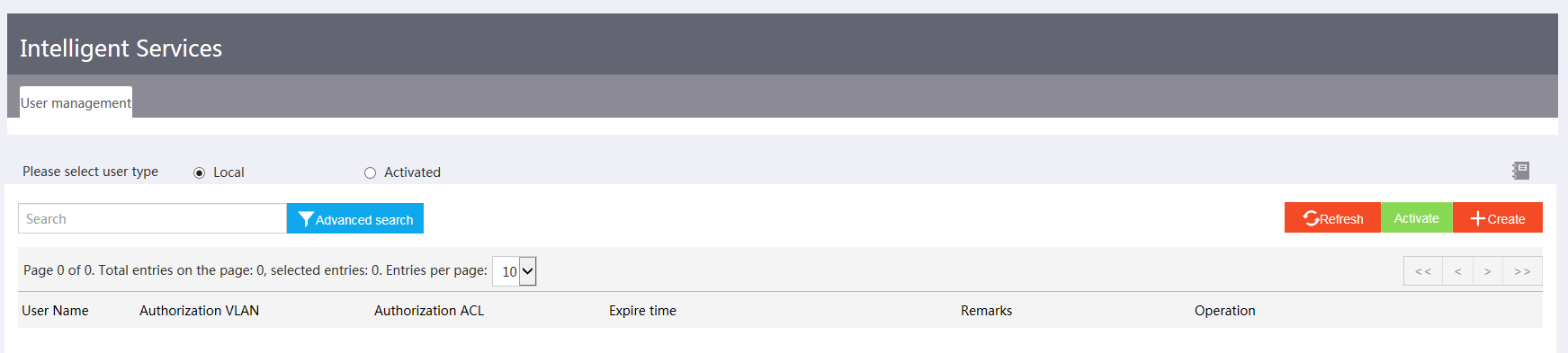
· Intelligent servicing—Includes user creation and activation.
With the SmartMC management platform, you can manage the SmartMC network topology and manage members in bulk.
Figure 2 through Figure 5 show example Web interfaces.
Figure 2 Intelligent management

Figure 3 Intelligent operation and maintenance
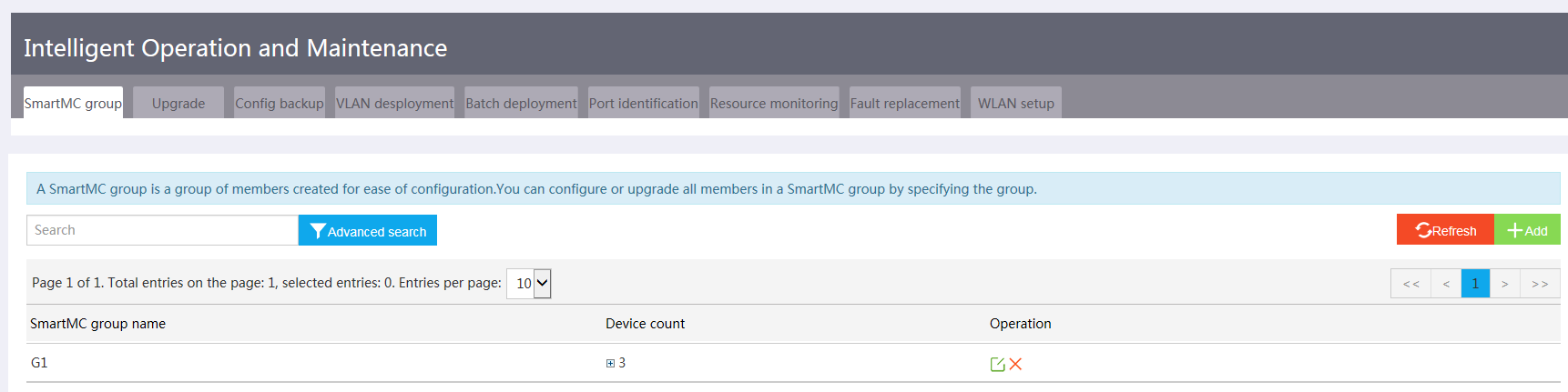
Figure 4 Visibility
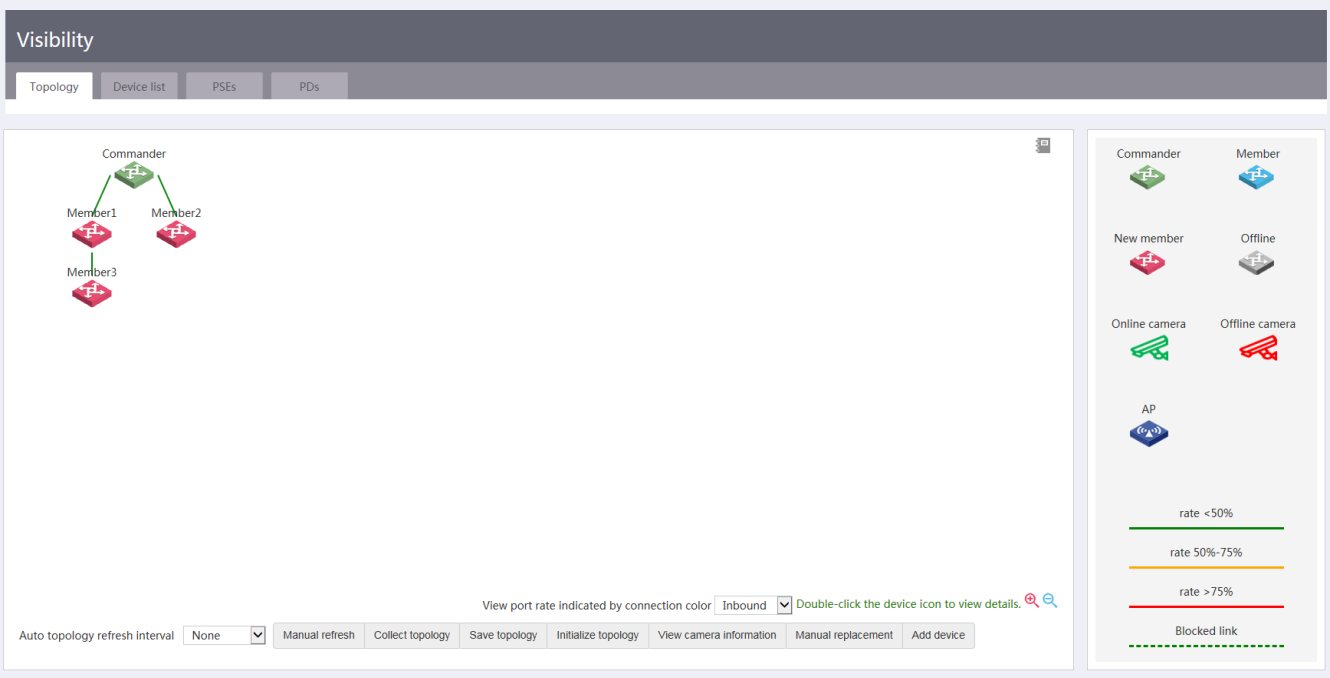
Figure 5 Intelligent servicing
Best practice configuration
Network requirements
As shown in Figure 6, an AP is connected to TC 3, two cameras are connected to TC 3, and one camera is connected to TC 1. Configure the TM in the SmartMC configuration wizard.
· Configure TCs to automatically join the SmartMC network or manually add TCs to the network.
· Configure the AP, TM, and TCs to communicate with each other in VLAN 1.
· Enable AC functions on the TM and configure TC 3 to supply power to the AP and the cameras through PoE.
· Enable camera monitoring on the TM.
· Enable SIP-based SQA on all TCs to monitor audio and video sessions.
· Enable automatic endpoint identification on the TM.

Deploying the SmartMC network
You can configure the members to join the network automatically or add them manually.
Configuring automatic deployment
Procedure
1. Configure the commander:
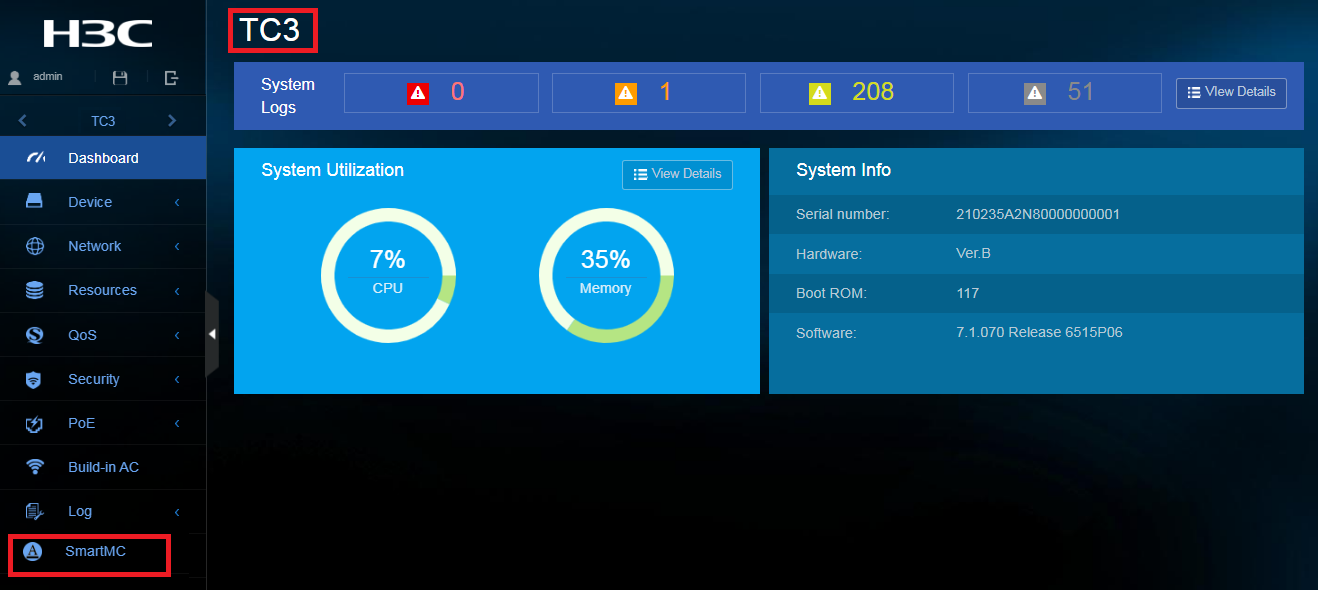
a. Log in to the commander and then click SmartMC from the left navigation pane.
Figure 7 SmartMC Web interface

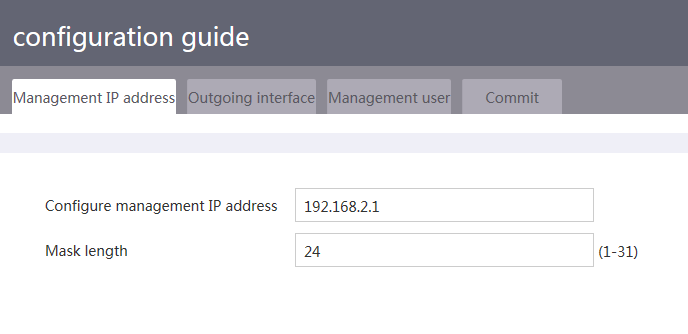
b. Specify the management IP address (IP address of VLAN-interface 1 on the commander).
Figure 8 Specifying the management IP address
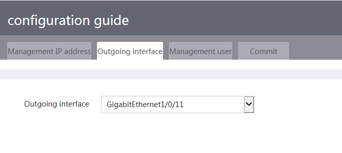
c. Specify the outgoing interface. Specify the interface on the commander that connects the commander to the current PC as the outgoing interface.
Figure 9 Specifying the outgoing interface
d. Specify the local user of the commander. You can specify an existing local user or a new local user. If you specify a new user, the system creates the user automatically.
Figure 10 Specifying the management user

e. Verify the commander settings.
Figure 11 Verifying the commander settings

2. Power on the members without loading any configuration. The members will join the SmartMC network automatically.
Verifying the configuration
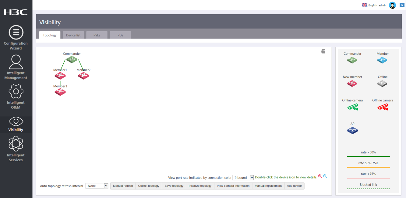
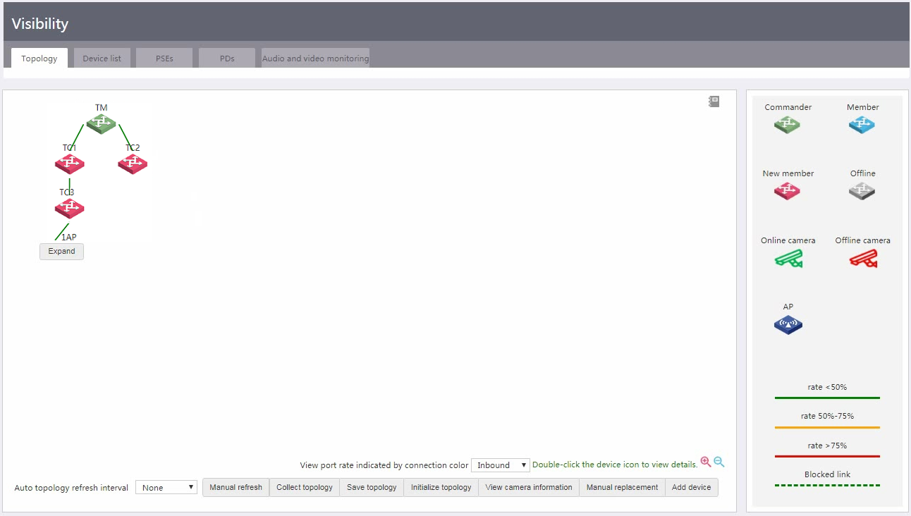
Access the Visibility > Topology page and view the network topology. Verify that members have joined the network as expected.
Figure 12 Network topology
Configuring manual deployment
For members that cannot join the network automatically, you can access the Visibility > Topology page and click Add device to manually add them one by one.
Before a manual adding, make sure the settings in Table 1 have been configured on the member to add.
Table 1 Required settings on members to add manually
|
Item |
Commands |
|
Specify an IP address for VLAN-interface 1. Make sure the IP address is in the same subnet as the IP address of VLAN-interface 1 on the commander. |
· interface vlan-interface 1 · ip address ip-address { mask-length | mask } |
|
Enable HTTP and HTTPS. |
· ip http enable · ip https enable |
|
Enable the Telnet service. |
telnet server enable |
|
Enable NETCONF over SOAP over HTTP. |
netconf soap http enable |
|
Enable LLDP globally. |
lldp global enable |
|
Create a user. Set the username and password to admin, add the telnet, http, and https service types, and authorize the user to use the network-admin user role. NOTE: Before configuring the password, lower the password complexity requirements for local users. |
· password-control length 4 · password-control composition type-number 1 type-length 1 · undo password-control complexity user-name check · local-user admin · password simple admin · service-type telnet http https · authorization-attribute user-role network-admin |
|
Set scheme authentication for VTY user lines 0 to 63. |
· line vty 0 63 · authentication-mode scheme |
|
Enable SNMPv2c and create read-only community public. |
· snmp-agent sys-info version v2c · snmp-agent community read public |
Figure 13 Manually adding a member

Specifying a file server
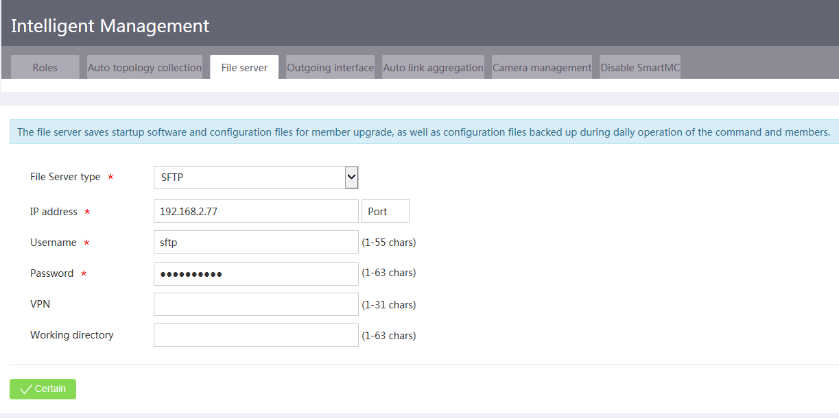
A file server is required for fault member replacement, device upgrade, bulk configuration file backup, and bulk configuration deployment.
To specify a file server, access the Intelligent Management > File server page and specify the file server parameters as needed.
Figure 14 Specifying a file server
Configuring unified wired and wireless maintenance
Unified wired and wireless maintenance integrates wired network management, basic wireless network management, and PoE power visibility functions, allowing unified management and statistics displaying for both the wired and wireless networks.
Configuring basic WLAN settings
Perform this task to add, delete, or modify wireless services, configure inter-AP Layer 2 isolation, and manage PoE power supply on all devices in the SmartMC network.
Prerequisites
Perform the following tasks to enable the AC function on the TM:
1. Install the feature image of the unified wired and wireless AC.
The feature image of the unified wired and wireless AC is contained in the switch software image package. When loading the feature image, make sure that the feature image version matches the switch software image version. To obtain the image of the unified wired and wireless AC, contact Technical Support.
2. Activate the feature image of the unified wired and wireless AC.
install activate feature filename&<1-30> slot slot-number [ test ]
3. Configure the feature image to remain activated after the system reboots.
install commit
4. Install licenses.
To increase the number of APs that the AC can manage, you must install licenses. For more information about installing licenses, see H3C Comware 7 and Comware 9 WLAN Products Local Licensing Guide at http://www.h3c.com/cn/home/qr/default.htm?id=607.
Restrictions and guidelines
By default, the authentication mode is PSK for created wireless services.
Procedure
1. Access the Intelligent O&M > WLAN setup page.
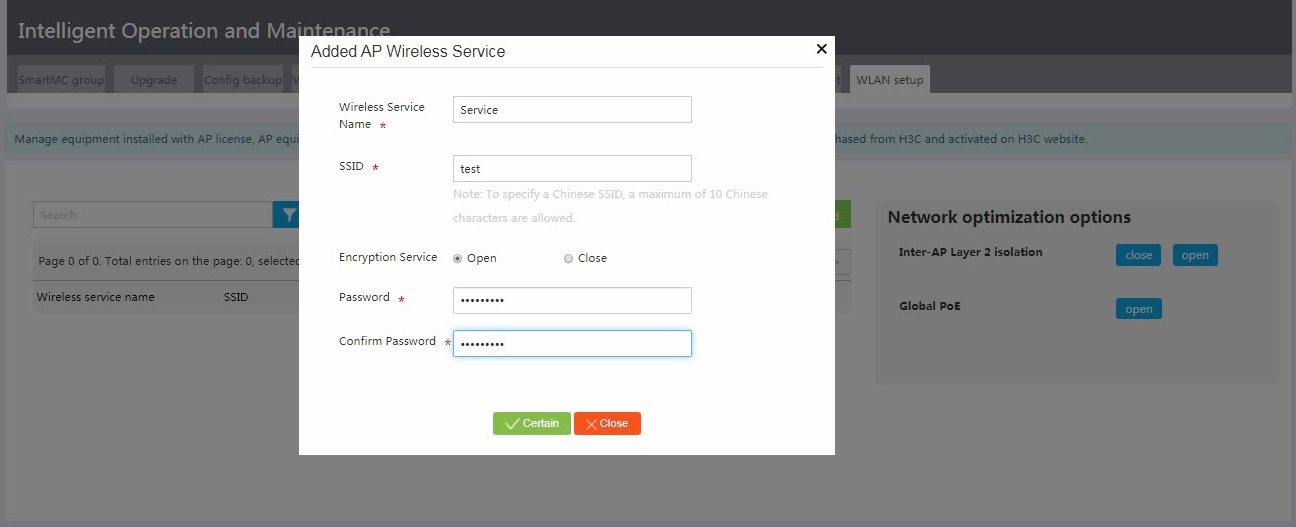
2. Click Add.
Figure 15 Adding a wireless service

3. Configure wireless service parameters and then click Confirm.
Figure 16 Configuring wireless service parameters
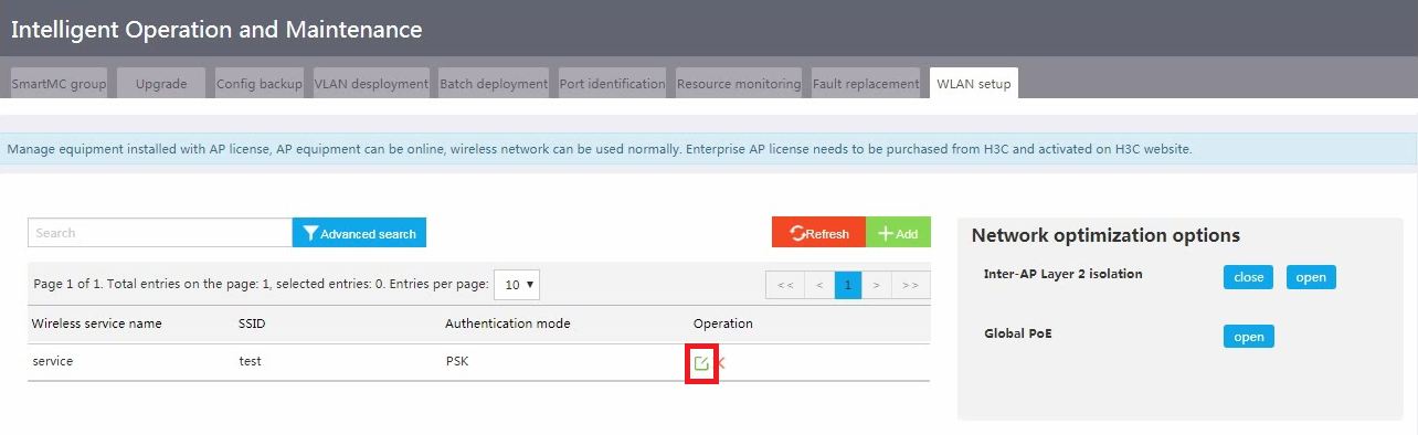
4. Click the Edit icon for the wireless service.
Figure 17 Editing a wireless service
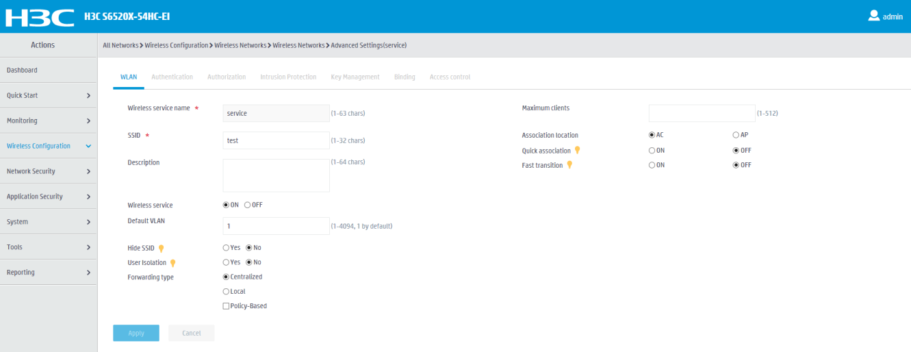
5. Configure advanced wireless service settings as needed.
Figure 18 Configuring advanced wireless service settings
Configuring PoE power supply
1. From the left navigation pane, click Visibility.
2. To view PSE information, click the PSEs tab. You can click an action link in the Actions column to view PSE details or PDs, or configure PoE power supply.
Figure 19 Viewing PSE information
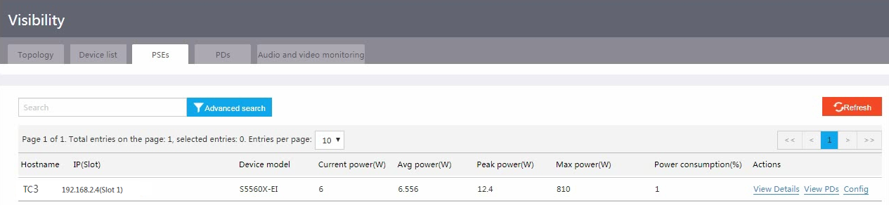
Figure 20 Viewing PSE details
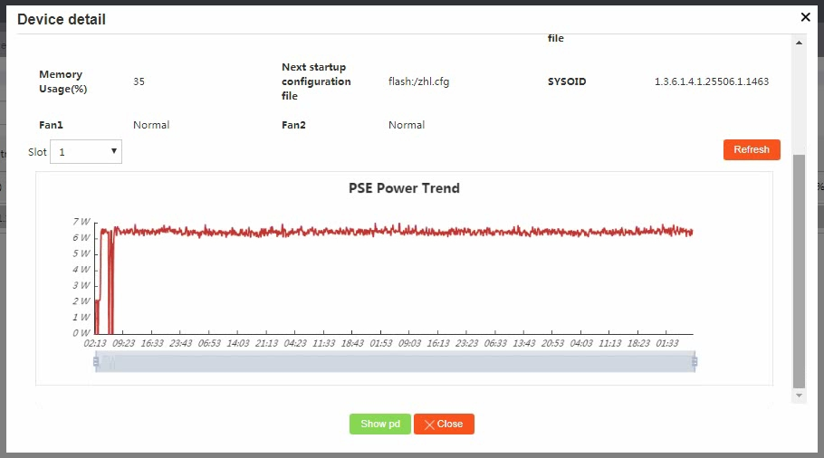
Figure 21 Configuring PoE power supply
3. To view PD information, click the PDs tab.
Figure 22 Viewing PD information

Viewing the network topology and device details
You can view the network topology on the Visibility > Topology page.
To view details information about an AP, click Expand.
To view neighbor information about a device, double click the device icon.
Figure 23 Viewing the network topology and device details
Configuring camera monitoring
Perform this task to monitor the association and disassociation of cameras in VLANs. With this feature configured, the system displays monitored cameras on the Visibility > Topology page and refreshes camera status in real time.
Managing cameras in static mode
To manage cameras in static mode, access the Intelligent Management > Camera management page and select Static for Management mode.
On the page that opens, you must specify parameters such as MAC addresses of cameras to be monitored, and the device will monitor associations and disassociations of the cameras by matching MAC address entries.
You can manage a single camera or manage multiple cameras in one operation.
Adding cameras to monitor
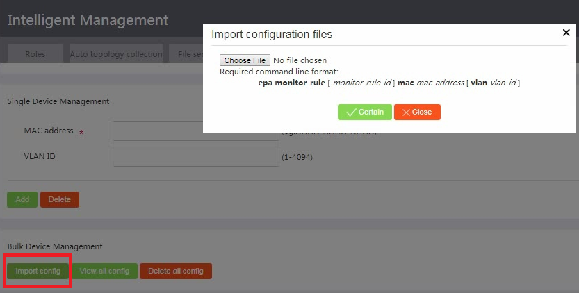
To add a single camera, specify the MAC address of the camera and the VLAN in which the camera will be monitored, and then click Add.
To add multiple cameras in bulk, click Import config, and then import a configuration file that contains camera information.
Figure 24 Import cameras to monitor
Viewing all monitored cameras
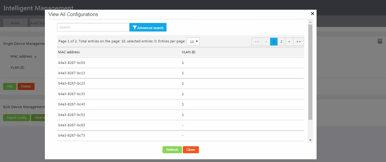
To view all camera monitoring configurations, click View all config.
Figure 25 Viewing all camera monitoring configurations
Deleting cameras
You can delete a camera or multiple cameras in bulk. (Details not shown.)
Managing cameras in dynamic mode
To manage cameras in dynamic mode, access the Intelligent Management > Camera management page and select Dynamic for Management mode.
In this mode, the device uses Open Network Video Interface Forum (ONVIF) to monitor associations and disassociations of ONVIF endpoints.
Dynamic camera management supports the following features:
· ONVIF Probe—Detects ONVIF endpoints in a network proactively. To use this feature, you must enable it on the TM VLAN interface in the same VLAN as the monitored endpoints.
· ONVIF Snooping—Identifies ONVIF endpoints and monitors associations and disassociations of ONVIF endpoints. To use the feature, you must enable it on the TCs or TM to which the ONVIF endpoints are directly connected.
· ONVIF Reset—Clears information about ONVIF endpoints detected on the specified interface. After the clearing, the device can detect the ONVIF endpoints again and generate updated endpoint information.
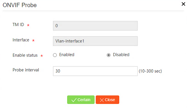
Enabling ONVIF probe
To enable ONVIF probe and configure the probe
interval, click the ![]() icon in the Operation column for a TM. With this feature enabled, the
device can detect ONVIF endpoints on the subnet where the VLAN interface
resides.
icon in the Operation column for a TM. With this feature enabled, the
device can detect ONVIF endpoints on the subnet where the VLAN interface
resides.
Figure 26 Accessing ONVIF probe configuration

Figure 27 Configuring ONVIF probe parameters
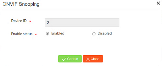
Enabling ONVIF snooping
To enable ONVIF snooping, click the ![]() icon in the Operation
column for a device (TM or TC) to which the monitored endpoint is directly
connected. With this feature enabled, the device can identify directly
connected ONVIF endpoints and monitor the associations and disassociations of
these endpoints.
icon in the Operation
column for a device (TM or TC) to which the monitored endpoint is directly
connected. With this feature enabled, the device can identify directly
connected ONVIF endpoints and monitor the associations and disassociations of
these endpoints.
Figure 28 ONVIF snooping configuration
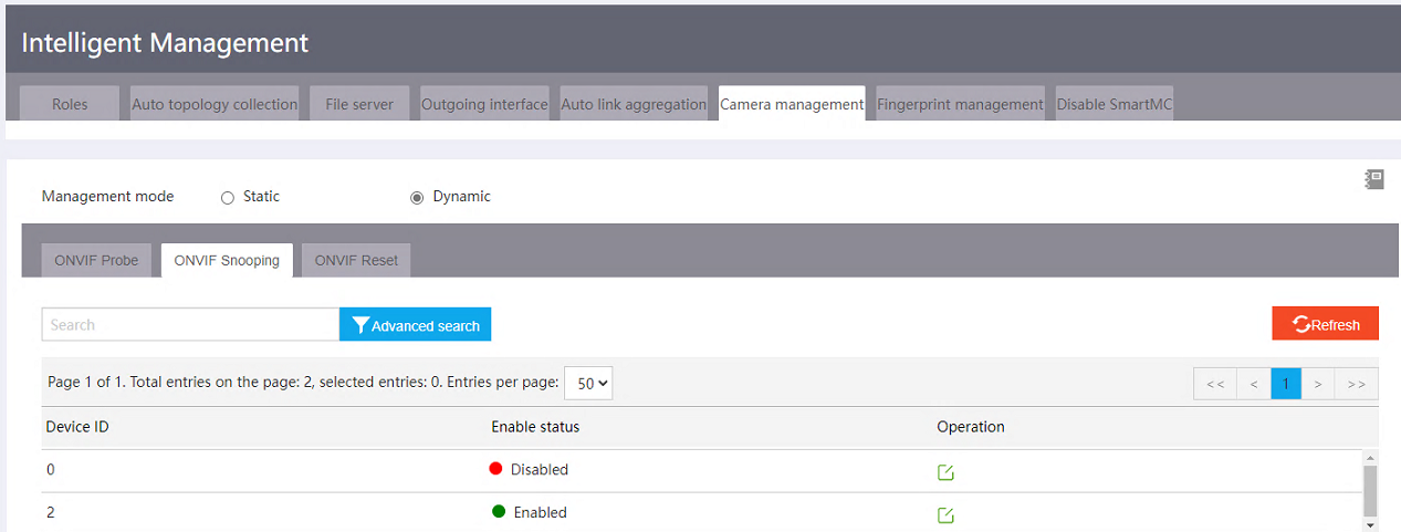
Figure 29 Enabling ONVIF snooping
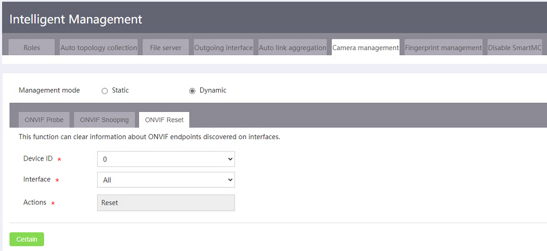
(Optional) Configuring ONVIF reset
To clear information about endpoints detected on an interface through ONVIF, click the ONVIF Reset tab, select the device and interface, and click OK. After the clearing, the device can detect the ONVIF endpoints again.
Figure 30 Configuring ONVIF reset
Viewing cameras in the topology
You can access the Visibility > Topology page to view monitored cameras in the topology.
Figure 31 Viewing cameras in the topology
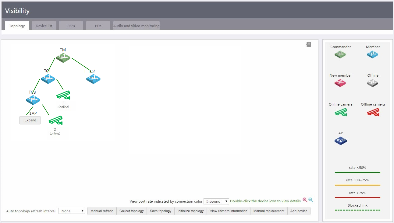
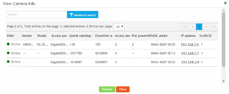
To view detailed information about monitored cameras, click View camera information.
Figure 32 Viewing detailed camera information
Configuring audio and video monitoring
Perform this task to monitor audio and video sessions for multimedia traffic. You can configure SIP-based service quality analysis (SQA) on devices one by one from the CLI or configure SIP-based SQA for multiple devices in bulk from the Web interface.
Configuring SQA
Configuring SQA on a single device from the CLI
You must perform this task on both the commander and members.
To configure SQA on a single device:
1. Enter system view.
system-view
2. Enter SQA view.
sqa
3. Enable SIP-based SQA.
sqa-sip enable
By default, SIP-based SQA is disabled.
4. (Optional.) Specify the SIP listening port number.
sqa-sip port port-number
By default, the SIP listening port number is 5060.
Make sure the SIP listening port number on the device is the same as that on the SIP server.
5. (Optional.) Specify an IP address range for SIP-based SQA.
sqa-sip filter address start-address end-address
By default, no IP address range is specified for SIP-based SQA. The device performs SQA on all SIP packets.
After this command is executed, the device performs SQA only on SIP calls in the specified IP address range.
Configuring SQA on multiple devices from the Web interface
1. Create configuration file Config.cfg and save the file to the file server. The content of the configuration file must contain the following commands:
<FTP Server> more Config.cfg
system-view
sqa
sqa-sip enable
sqa-sip port 5066
sqa-sip filter address 192.168.56.1 192.168.56.244
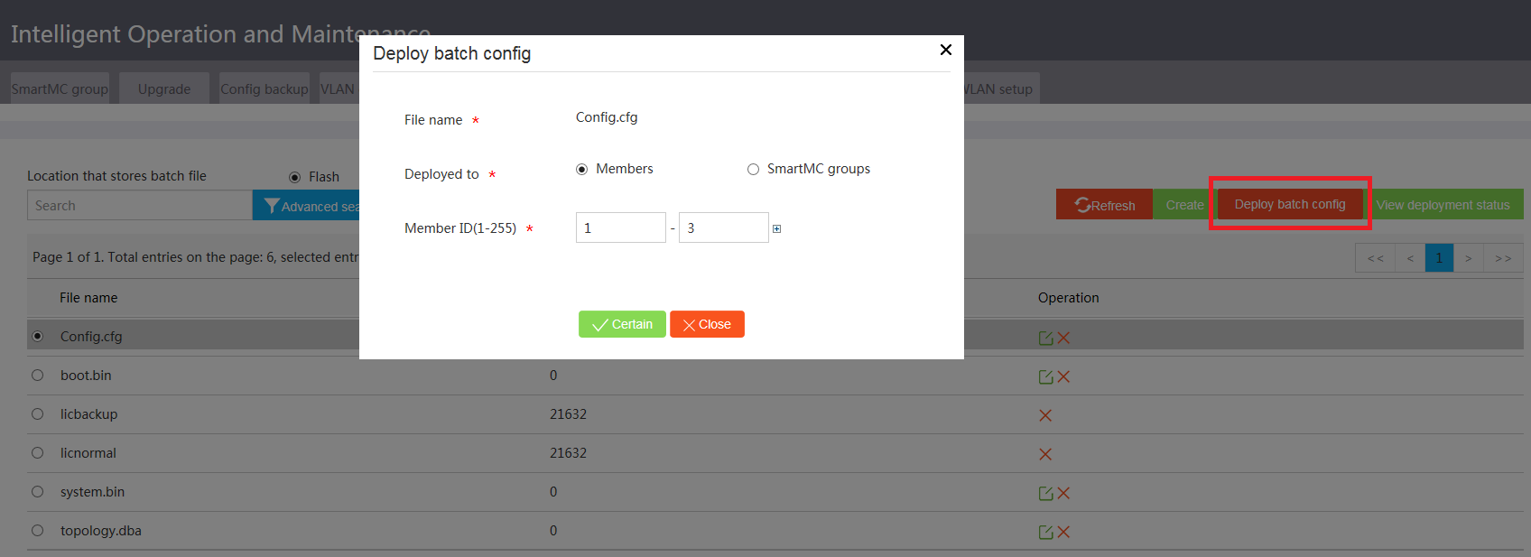
2. Access the Intelligent O&M > Batch deployment page, select the file server as the batch file storage location, and select Config.cfg from the file list.
3. Click Deploy batch config.
4. Select Members as the deployment object, specify the member ID range, and then click Confirm.
Figure 33 Deploying a batch configuration file
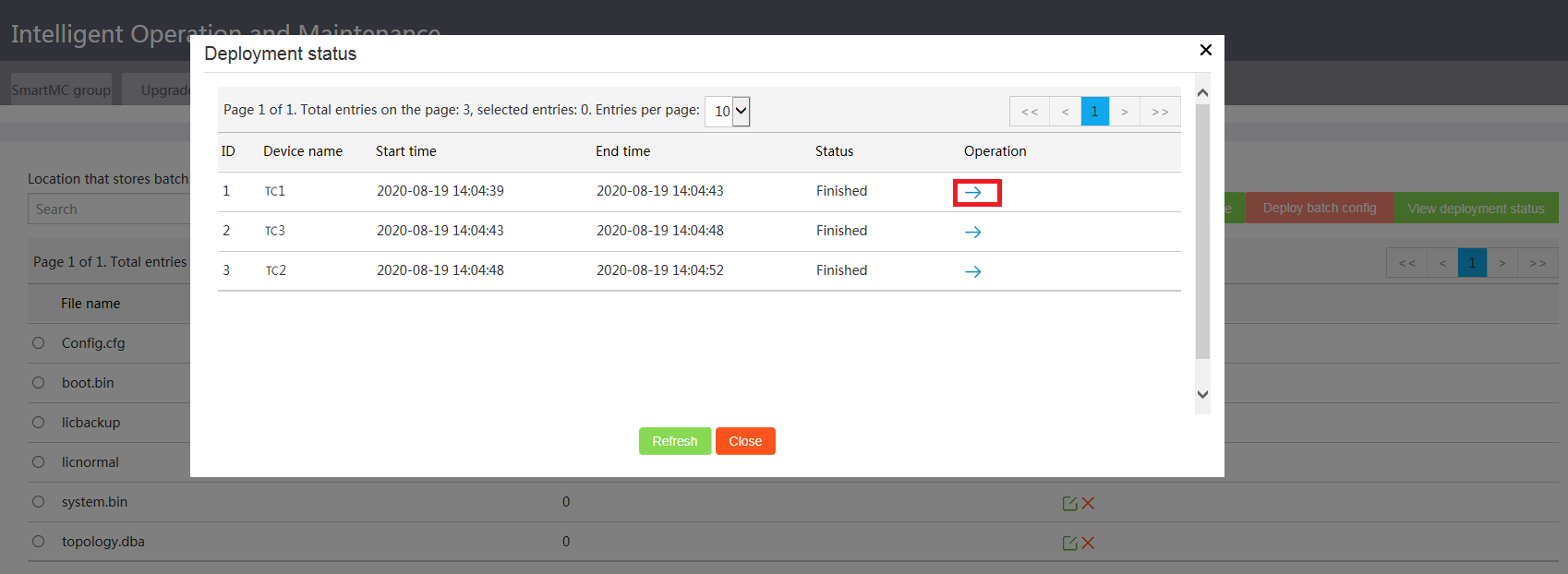
5. Click View deployment status to verify the deployment result.
To view deployment details, click the right chevron icon.
Figure 34 Viewing the deployment status
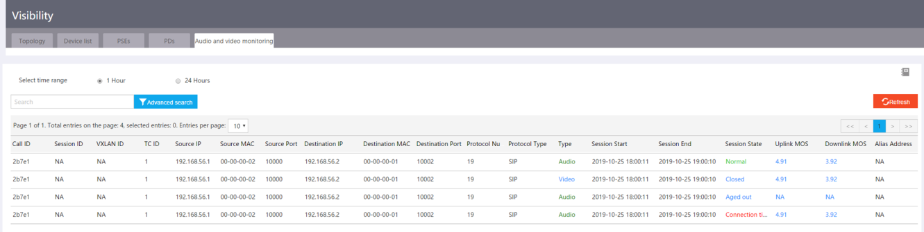
Viewing audio and video monitoring information
You can access the Visibility > Audio and video monitoring page to view detailed information about audio and video monitoring and identify session quality based on the uplink and downlink MOS values.
Figure 35 Viewing audio and video monitoring information
|
|
NOTE: The device whose TC ID is 0 is the commander. A higher MOS value represents a higher session quality. MOS values are in the range of 0 to 5. · 0 to 1—Extremely poor session quality. · 1 to 2—Poor session quality. · 2 to 3—Average session quality. · 3 to 4—Good session quality. · 4 to 5—Excellent session quality. · N/A—The system fails to obtain the MOS value. |
Automatic endpoint identification
When an endpoint accesses the network, a TM or TC obtains fingerprint information from the authentication request of an endpoint and matches the fingerprint with the endpoint identification rules. If a match is found, the device considers that the endpoint is online, records the MAC address, endpoint category, and vendor of the endpoint, and sends the information to the TM for unified display. Devices that support automatic endpoint identification are mobile phones, tablets, laptops, and routers.
The following fingerprint types are supported:
· DHCP Option 55 fingerprint—Parameter request list option. The option is used by an endpoint to request specified configuration parameters. To use this fingerprint, enable DHCP snooping entries on the access interface of endpoints and configure the access interface as a trusted port.
· HTTP user agent fingerprint—Located in the header of HTTP requests to carry information about the endpoint operating system, Web browser, and versions. To use this fingerprint, enable portal authentication on the access interface of endpoints.
· MAC address fingerprint—MAC address of the endpoint or MAC address range to which the endpoint belongs.
The device matches fingerprint information for an endpoint in the following order:
· Static camera monitoring rules.
· DHCP Option 55 fingerprint.
· HTTP user agent fingerprint.
· MAC address fingerprint.
Identifying an endpoint through DHCP Option 55 fingerprint
As a best practice, connect endpoints to TCs in the SmartMC network. Configure the TM interface to act as the DHCP server and enable DHCP snooping on TCs. After an endpoint comes online through DHCP, the corresponding TC can identify the endpoint by using the DHCP Option 55 fingerprint.
Configuring the TM interface to act as the DHCP server
1. Enter system view of the TM.
system-view
2. (Optional.) Specify IP addresses excluded from automatic address allocation.
dhcp server forbidden-ip start-ip-address [ end-ip-address ] [ vpn-instance vpn-instance-name ]
By default, all IP addresses in the DHCP address pool, except for the IP address of the DHCP server interface, are available for automatic address allocation.
3. Create a DHCP address pool and enter its view.
dhcp server ip-pool pool-name
4. Specify the subnet for dynamic allocation in the DHCP address pool.
network network-address [ mask-length | mask mask ]
By default, no subnet is specified in a DHCP address pool.
5. (Optional.) Set the lease duration in the DHCP address pool.
expired { day day [ hour hour [ minute minute [ second second ] ] ] | unlimited }
By default, the lease duration is 1 day.
6. Return to system view.
quit
7. Enable DHCP.
dhcp enable
By default, DHCP is disabled.
Enabling DHCP snooping on the TC globally
1. Enter system view of the TC.
system-view
2. Enable DHCP snooping globally.
dhcp snooping enable
By default, DHCP snooping is disabled.
3. Enter interface view.
interface interface-type interface-number
Specify the interface connected to endpoints.
4. Specify the port as a trusted port.
dhcp snooping trust
By default, all ports are untrusted after DHCP snooping is enabled.
Identifying an endpoint through HTTP user agent fingerprint
As a best practice, connect endpoints to TCs in the SmartMC network. Enable portal authentication on the TC. After an endpoint comes online through portal authentication, the corresponding TC can identify the endpoint by using the HTTP user agent fingerprint.
To configure portal authentication for automatic endpoint identification through HTTP user agent fingerprint:
1. Enter system view of a TC.
system-view
2. Create an ISP domain and enter its view.
domain isp-name
By default, an ISP domain named system exists.
3. Enable local portal authentication.
authentication portal local
By default, the default authentication method in the ISP domain is used.
4. Configure local portal authorization.
authorization portal local
By default, the default authorization method in the ISP domain is used.
5. Configure local portal accounting.
accounting portal local
By default, the default accounting method in the ISP domain is used.
6. Return to system view.
quit
7. Create a portal Web server and enter its view.
portal web-server server-name
8. Specify a URL for the portal Web server.
url url-string
By default, no URL is specified for the portal Web server.
9. Return to system view.
quit
10. Enter interface view.
interface interface-type interface-number
11. Configure direct portal authentication.
portal enable method direct
By default, portal authentication is disabled on an interface.
12. Apply a portal Web server.
portal apply web-server server-name
By default, no portal Web server is applied.
13. Return to system view.
quit
14. Return to user view.
quit
15. Obtain an authentication page file from the TFTP server.
tftp tftp-server get source-filename
16. Enter system view.
system-view
17. Enable the HTTP-based local portal Web service.
portal local-web-server http
18. Specify the default authentication page file for a local portal Web service. For the feature to take effect, make sure the authentication page file already exists in the root directory of the storage medium on the device.
default-logon-page file-name
19. (Optional.) Specify the listening port for the HTTP-based local portal Web service.
tcp-port port-number
By default, the number of the listening port is 80.
Configuring fingerprints on a TM
A fingerprint entry records a set of fingerprint information, including the fingerprint type, fingerprint value, endpoint type, endpoint category, endpoint vendor, and endpoint OS. The TM is predefined with some common fingerprints and you can add fingerprints based on network requirements.
To add a fingerprint, access the Intelligent Management > Fingerprint management page and then click Add.
Figure 36 Accessing fingerprint management
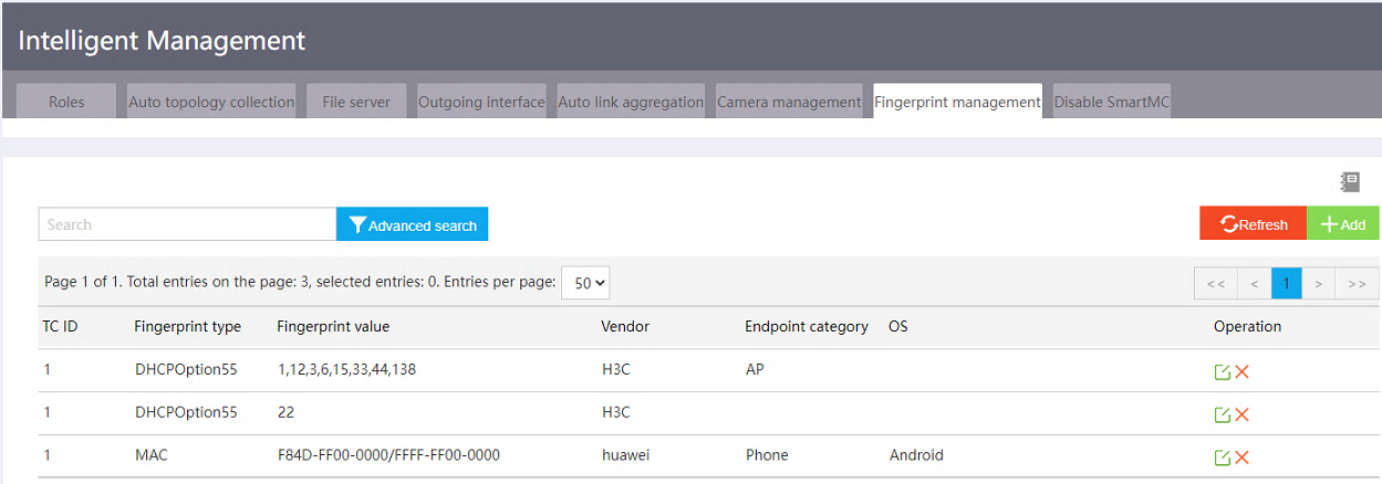
Figure 37 Adding a fingerprint
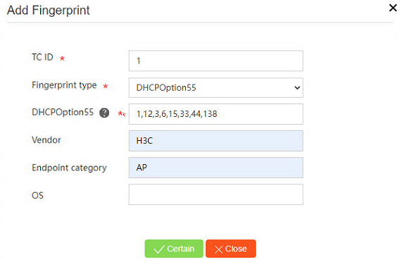
Newly added or edited fingerprints take effect only on endpoints that come online afterwards. For online endpoints to match the new or modified fingerprints or for the system to update the displayed fingerprint information, you must reconnect the endpoints to the network.
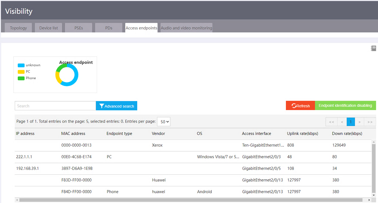
Viewing online clients
To view access client information, access the Visibility > Access endpoints page and then click Endpoint identification enabling. After endpoint identification is enabled, when an endpoint accesses the SmartMC network, the TC compares the endpoint information with the configured endpoint fingerprints. If a match is found, the TC records the MAC address, category, and vendor of the endpoint, and sends the endpoint information to the TM for unified display.
Figure 38 Viewing online clients
SmartMC feature specifications
|
Item |
Value |
|
Maximum number of supported members |
64 |
|
Maximum number of supported APs |
Same as the number supported by the unified wired and wireless AC on the commander |
|
Maximum number of supported camera monitoring rules |
512 |
|
Maximum number of supported SIP sessions on the commander or a member |
1000 |
SmartMC restrictions and guidelines
As a best practice, use the automatic method to deploy the SmartMC network.
To use PoE, make sure the deployed devices are PoE-capable.
A SmartMC network is established in VLAN 1. For the network to work correctly, do not configure security settings in VLAN 1.
Recommended devices for SmartMC
|
Device model |
TM |
TC |
Recommended version |
Remarks |
|
S6520-SI |
Supported |
Supported |
F6509L01 or higher |
· Dynamic camera monitoring (ONVIF) is supported only in F6615 and higher versions. · Unified wired and wireless ACs and basic WLAN settings are supported only in R6522 and higher versions. |
|
S6520X-SI |
Supported |
Supported |
||
|
S6520X-EI |
Supported |
Supported |
||
|
S6520X-HI |
Supported |
Supported |
||
|
S5560X-30F-HI S5560X-54F-HI |
Supported |
Supported |
R6530P01 or higher |
|
|
S5560X-34C-HI S5560X-58C-HI |
Supported |
Supported |
R6615P03 or higher |
|
|
MS4600 |
Supported |
Supported |
F6509L01 or higher |
· Dynamic camera monitoring (ONVIF) and automatic endpoint identification are supported only in R6615P03 and higher versions. · Unified wired and wireless ACs and basic WLAN settings are supported only in R6522 and higher versions. |
|
S5000-EI |
Supported |
Supported |
F6509L01 or higher |
|
|
S5560X-EI |
Supported |
Supported |
F6509L01 or higher |
· Dynamic camera monitoring (ONVIF) and automatic endpoint identification are supported only in F6615 and higher versions. · Unified wired and wireless ACs and basic WLAN settings are supported only in F6512P01 and higher versions. |
|
MS4520V2-30F |
Supported |
Supported |
F6509L01 or higher |
· Dynamic camera monitoring (ONVIF) and automatic endpoint identification are supported only in R6615P03 and higher versions. · Unified wired and wireless ACs and basic WLAN settings are supported only in F6512P01 and higher versions. |
|
MS4520V2-30C MS4520V2-54C |
Supported |
Supported |
R6510P01 or higher |
|
|
S5500V2-EI |
Supported |
Supported |
F6509L01 or higher |
|
|
S5560S-EI |
Supported |
Supported |
R6318P01 or higher |
· Devices of these series do not support SIP-based SQA. · Devices of these series do not support unified wired and wireless ACs and basic WLAN settings. · Static camera management and automatic endpoint identification are supported only in R6328 and higher versions. · Dynamic camera monitoring (ONVIF) is supported only on S5130S-EI series switches of R6338 and higher versions. · Devices of these series can act as TMs. As a best practice, configure device roles as recommended. |
|
S5560S-SI |
Supported |
Supported |
||
|
S5500V3-SI |
Supported |
Supported |
||
|
MS4520V2 |
Supported |
Supported |
||
|
S5130S-HI |
Not supported |
Supported |
||
|
S5130S-EI |
Not supported |
Supported |
||
|
S5130S-SI |
Not supported |
Supported |
||
|
MS4320V2 |
Not supported |
Supported |
||
|
MS4320 |
Not supported |
Supported |
||
|
MS4300V2 |
Not supported |
Supported |
||
|
MS4200 |
Not supported |
Supported |
||
|
S5130S-LI |
Not supported |
Supported |
||
|
S5120V2-SI |
Not supported |
Supported |
||
|
S5120V2-LI |
Not supported |
Supported |
||
|
E100C |
Not supported |
Supported |
||
|
E500C |
Not supported |
Supported |
||
|
E500D |
Not supported |
Supported |
||
|
S5110V2 |
Not supported |
Supported |
||
|
S5110V2-SI |
Not supported |
Supported |
||
|
S5000V3-EI |
Not supported |
Supported |
||
|
S5000E-X |
Not supported |
Supported |
||
|
S3100V3-EI |
Not supported |
Supported |
||
|
S3100V3-SI |
Not supported |
Supported |
||
|
S1850-X |
Not supported |
Supported |
||
|
S5000V5-EI |
Not supported |
Supported |
Release 6319P01 or higher |
|
|
S5120V3-SI |
Not supported |
Supported |
R6329 or higher |
|
|
S5120V3-LI |
Not supported |
Supported |
R6329 or higher |
|
|
S5000X-EI |
Not supported |
Supported |
R6329 or higher |
|
|
S1850V2-X |
Not supported |
Supported |
R6329 or higher |
|
|
MS4320V3 |
Not supported |
Supported |
R6329 or higher |
|
|
S1850V2-EI |
Not supported |
Supported |
R6330 or higher |
|
|
E500C-F |
Not supported |
Supported |
R6338 or higher |
