- Released At: 18-04-2024
- Page Views:
- Downloads:
- Table of Contents
- Related Documents
-
iFIT Technology White Paper
Copyright © 2024 New H3C Technologies Co., Ltd. All rights reserved.
No part of this manual may be reproduced or transmitted in any form or by any means without prior written consent of New H3C Technologies Co., Ltd.
Except for the trademarks of New H3C Technologies Co., Ltd., any trademarks that may be mentioned in this document are the property of their respective owners.
The content in this article contains general technical information, and some information may not be applicable to the product you purchased.
Contents
End-to-end performance statistics
Hop-by-hop performance statistics
Packet encapsulation format (non-China Mobile standard format)
iFIT packet encapsulation format in the MPLS/SR-MPLS network
iFIT packet encapsulation format in the SRv6 network
Packet encapsulation format (China Mobile standard format)
iFIT packet encapsulation format in the MPLS/SR-MPLS network
iFIT packet encapsulation format in the IPv6 (SRv6/G-SRv6/G-BIER) network
Packet loss measurement mechanism
Measurement data reporting mechanism
Performing iFIT measurement on the MPLS L3VPN HoVPN network
Performing iFIT measurement on the L3VPN over SRv6 network
Overview
Technical background
With the widespread use of networks and the development of communication technology, various network services are emerging, and new services require higher network performance. Among them, voice and video frequency services are the most widely used in numerous network services, and they are highly sensitive to network packet loss, delay, and jitter. High packet loss rate and large delay can cause voice card stuttering and video frequency mosaic, affecting user experience and, in severe cases, leading to communication anomalies. When the quality of voice and video frequency services declines, users hope to quickly locate and eliminate network outages.
Currently, there are two major categories of methods for packet loss and delay measurement in IP networks.
· Indirect measurement: By simulating the situation of sending real service packets, the packet loss rate and delay of the simulated packets are calculated. The service packets loss rate and delay are indirectly obtained from this process.
· Direct measurement: By directly detecting the transmission and reception of real service packets, we obtain the packet loss rate and delay of the service packets.
Table 1 provides a description of common packet loss and delay measurement techniques. When these techniques are applied in small-scale network environments, they can quickly identify packet loss and delay issues. However, in large-scale network environments, these techniques present challenges such as slow identification speed, high consumption, and difficulty in locating issues.
Table 1 Description of common packet loss and delay measurement
|
Measurement Method |
Traditional measurement technology |
Description |
|
Indirect measurement |
· Ping · iNQA · TWAMP Light (Two-way active measurement protocol) is a protocol for active measurement of bidirectional network performance. |
· It only supports three-tier network. · By continually attempting to establish a connection with the potentially faulty device, the scope of fault detection is gradually narrowed down, but this process can be time-consuming. · Supports only point-to-point scenarios. · Simulate packet sending, the detection result is not realistic enough. |
|
Direct measurement |
Y.1731, also known as connectivity fault detection (CFD), is a standard for identifying and locating network issues. |
· Only supports Layer 2 network. · By continually attempting to establish a connection with the potentially faulty device, the fault detection scope is gradually narrowed down, resulting in a longer localization time. · Supports point-to-point, point-to-multipoint, and multipoint-to-multipoint scenarios. · Detect packet loss for real network packets, and the detection result is genuine. |
|
RFC 6374/6375 (packet loss and delay measurement in MPLS networks) |
· Only supports MPLS network. · By continuously monitoring the packet loss situation of each section, we gradually narrow down the range of packet loss, which might prolong the positioning time. · Only supports point-to-point scenario. · Perform packet loss detection on real packets, and the detection result is accurate. |
|
|
INT |
· Supports general second and third stratum Ethernet, EVPN, and VXLAN networks. · The head node matches and mirrors the packets, then adds an INT header to the mirrored packets. Middle nodes and tail nodes automatically identify the INT packets and apply corresponding INT processing. The tail node exports the collected information in the INT header to a collector for analysis and presentation. · The detection precision is high, yielding a wealth of information collected. · The network overhead is significant. |
|
|
iNQA |
· Supports both Layer 2 and Layer 3 network. · The positioning speed is fast. After deploying iNQA in the network, iNQA will automatically measure the packet loss parameter at each measurement point (MP) periodically. · Supports a variety of scenarios such as point-to-point, point-to-multipoint, and multipoint-to-multipoint. · Perform packet loss detection on actual packets, and the detection result is real. |
In-situ Flow Information Telemetry (iFIT) is a detection method used in MPLS, SR-MPLS, SRv6, G-SRv6, and G-BIER networks. It obtains the real packet loss rate and delay of the network by directly measuring service packages. Its principles mainly follow RFC 8321, with the advantages of easy deployment and high statistical precision.
|
|
NOTE: Refer to the actual conditions of your device for information on iFIT support for G-SRv6 and G-BIER networks, as it depends on the device model. |
Benefits
iFIT has the following advantages over traditional packet loss measurement techniques:
· High detection precision: By directly measuring service packets, the collected data can accurately reflect the network quality status.
· Ease of deployment—The transit and end nodes generate telemetry data based on the iFIT packets.
· Rapid fault isolation—Use of on-path telemetry techniques enables close monitoring of flows in real-time to provide high-precision measurement of delay and packet loss.
· Visualized insights—The AD-WAN controller presents visualized iFIT telemetry data to help administrators quickly locate performance bottlenecks and points of failure.
· Supports the path auto-discovery function: iFIT adds packet headers to the service processes that users care about at the ingress nodes in the network. Downstream devices can automatically identify this service traffic and generate statistical measurement information based on the iFIT headers. The analyzer can perceive the real-time path of the service traffic in the network through this function.
· Based on hardware implementation, the impact on the network is minimal, and it has strong expansion capabilities.
iFIT network model
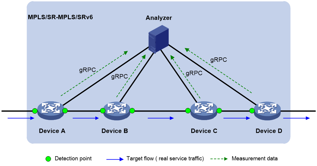
As shown in Figure 1, the iFIT network model includes the following key elements: target flow, target traversal network, statistical system, and MP.
Figure 1 Schematic diagram of the iFIT network model
Target flow
The target flow is the target object that iFIT records. Depending on the generation method, target flows are divided into two types: static flows and dynamic flows.
· Static flow—A static flow is a manually configured flow matching rule on the ingress node. After you complete the iFIT static flow configuration using the CLI on the ingress node and enable iFIT measurement, an iFIT static flow will be generated on the ingress node. The supported matching rules on the device include 5-tuple elements (source IP address/network segment, source port, destination IP address/network segment, destination port, and protocol type), DSCP, VPN, and next hop parameters.
An iFIT header is encapsulated in service packets and contains key parameters such as device ID, flow ID, measurement period, measurement mode, whether to measure delay, and whether to measure packet loss.
¡ Device ID: A device ID uniquely identifies a device included in iFIT measurement.
¡ Flow ID: A flow ID is automatically generated on the ingress node. It will be encapsulated in the iFIT headers and sent to a transmit node and the egress node to uniquely identify a target flow along with the device ID on an iFIT network.
¡ Measurement period: The device performs iFIT measurement periodically. A measurement period refers to the time interval from the start of a measurement to the collection and reporting of the measurement data.
¡ Measurement mode: Indicates end-to-end measurement or hop-by-hop measurement.
· Dynamic Target Stream: The Dynamic Target Stream refers to the service flow that the device dynamically learns.
¡ For the incoming node, if the device receives a packet that matches the configuration of the static target flow, the node will generate a dynamic target flow with the same Flow ID as the static flow.
¡ For intermediate and egress nodes, they generate dynamic target flows by resolving received packets and dynamically learning from the iFIT headers carried in the packets.
· Dynamic flow—A dynamic flow is a service flow dynamically learnt by the device. Dynamic flows are generated as follows:
¡ For the ingress node, if the device receives a service flow that matches the flow match criteria of a static flow, a dynamic flow with the same flow ID as the static flow is generated.
¡ For a transmit node and the egress node, they parse the received service packets and generate dynamic flows by dynamically learning from the iFIT headers of the service packets.
The device uses the device ID and flow ID in the iFIT header to identify the flow. If the device does not receive the packets using the same device ID and the same flow ID for a period of time, the device will delete the dynamic flow entry.
|
|
NOTE: Support for the device ID field in an iFIT header depends on the device model. Please rely on the actual condition of the device. · For products that support the DeviceID field, DeviceID+FlowID is the identifier for an iFIT flow · For products that do not support the DeviceID field, FlowID is the identifier of an iFIT flow. |
Transmit network
A transmit network is a network for transmitting the target flow, which neither originates nor terminates within that network. Currently, the supported transmit network can only be a Layer 3 network, and the devices within the network must be route accessible.
Measurement system
The measurement system is a collection of all devices completing iFIT statistics, which includes the following roles:
· Ingress node: The device where the target flow enters the transmit network, and is the starting point of MPLS, SR-MPLS, SRv6, G-SRv6, or G-BIER tunnels. It is responsible for filtering the target flow, adding the iFIT headers to it, collecting statistical data from the flow, and reporting it to the analyzer.
· Transmit node: It automatically identifies the iFIT target flow based on whether the packet contains an iFIT header, and then decides whether it needs to collect statistical data of the target flow and report it to the analyzer, based on the measurement type carried in the iFIT header.
· Egress node: This is the endpoint of MPLS, SR-MPLS, SRv6, G-SRv6, or G-BIER tunnels, where the target data flow exits the network device. The egress node automatically identifies the iFIT target data flow based on whether or not the packet includes an iFIT header, collects statistical data from the target data flow, and reports it to the analyzer. Eventually, it duplicates and strips off the iFIT header from the target data flow.
· Analyzer: It is responsible for collecting statistical data from the ingress nodes, transmit nodes, and egress nodes, and then complete the summarizing and calculation of the data.
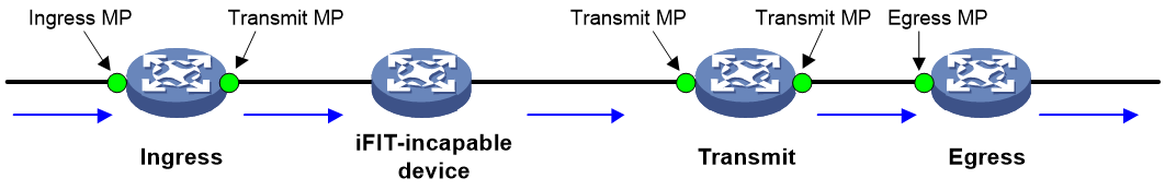
Measurement point
An MP is an interface where iFIT measurement is performed. Based on the different locations of the MPs in the measurement system, the MPs can be categorized into the following types:
· Ingress MP: Interface where the target flow enters the transmit network.
· Transmit MP: Interface through which the target flow transmits across the transmit network.
· Egress MP: Interface where the target flow leaves the transmit network.
|
|
NOTE: Different products support varying positions for the MPs. · Some products require that the egress MP must be the interface for a target flow to enter the egress node. This document uses this scenario as an example. · Some products require that the egress MP must be the interface for a target flow to leave the egress node. |
Figure 2 MP diagram
Application scenarios
iFIT supports two application scenarios: end-to-end performance statistics and hop-by-hop performance statistics.
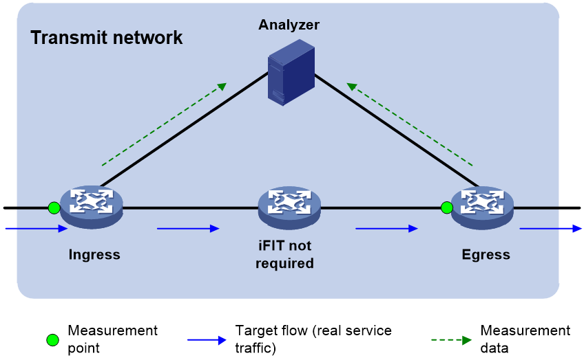
End-to-end performance statistics
The end-to-end performance statistics scenario is used to measure whether there are packet losses and delay parameters between the device where traffic enters the network (traffic ingress) and the device where traffic leaves the network (traffic egress).
As shown in Figure 3, iFIT can be used to directly measure whether there is packet loss and delay when traffic flows from Ingress to Egress and calculate the packet loss rate and delay value.
Figure 3 End-to-end performance statistics
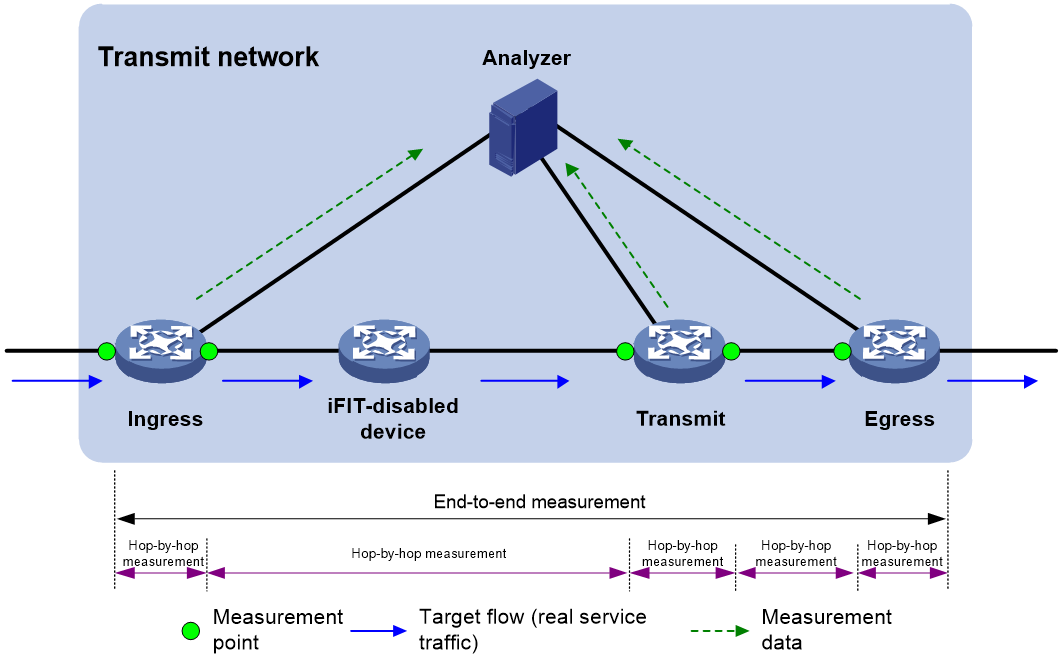
Hop-by-hop performance statistics
The hop-by-hop packet loss statistics scenario is used for measuring packet loss and delay within smaller network units. After identifying packet loss or delay end to end, the network can be divided into smaller measurement sections between the endpoints. This allows for determining whether packet loss and delay exist between every two units, in order to further identify the location of network elements affecting the network performance.
As shown in Figure 4, traffic goes from Ingress to Egress. iFIT can simultaneously measure whether there is any packet loss and delay between any two measuring points, and calculate the packet loss rate and delay value.
Figure 4 Hop-by-hop performance statistics
Concepts
Instance
iFIT implements independent measurement and statistics of different target flow packet loss and delay parameters through instances.
An instance is a logical concept and the smallest configuration unit of iFIT. Users need to create an instance on the ingress node, where they can specify parameters such as target flow and measurement period. By binding the instance to the incoming interface of the target flow, the performance parameters of the target flow received on the specified interface can be measured and statistically analyzed.
An instance is bound to a target flow. By configuring multiple instances and binding them to different target flows, you can simultaneously measure and gather performance parameters of various target flows.
Measurement period
After the measurement function in the iFIT instance is activated on the device, iFIT will continuously measure the performance parameters of the target flow bound to this instance. To facilitate users to understand the performance parameters of the target flow at any time, iFIT measures the performance parameters of the target flow in fixed durations (configurable via command line) as periods. The ingress node, middle node, and egress node calculate the total number of target packets received or transmitted during each period, and the analyzer calculates the packet loss parameters for each period. The ingress node, middle node, and egress node record the timestamp of the first packet received or transmitted in each period, and the analyzer calculates the delay parameters for each period.
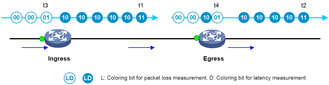
Coloring bit
The coloring bit, also known as the mark bit, can periodically identify the target flow, achieving the purpose of periodically sampling and collecting statistics on the target flow.
iFIT uses two coloring bits: one for loss measurement to calculate packet loss parameters, and the other for delay measurement to calculate delay parameters.
Packet encapsulation format (non-China Mobile standard format)
|
|
NOTE: In the early stages of iFIT development, drafts were actively evolving, and there were no RFCs. To facilitate iFIT packet communication among major manufacturers, China Mobile, H3C, Huawei, and other communication companies developed a set of iFIT enterprise standard (referred to as "Mobile enterprise standard" in this document). This standard defines the iFIT header structure, header payload location, and packet analysis for iFIT results reporting. Therefore, this document separately describes the different requirements between non-Mobile enterprise standard and Mobile enterprise standard (for example, iFIT header encapsulation). Content without a specific Mobile enterprise standard label indicates that it is applicable to both non-Mobile enterprise standard and Mobile enterprise standard. |
To achieve high-precision performance measurement while simplifying the deployment of the entire statistical system as much as possible, iFIT introduces the concept of iFIT headers. iFIT adds an iFIT header to the target flow packet at the ingress node, passing information such as FlowMonID and measurement period through the iFIT header to the transmit nodes and egress nodes.
iFIT packet encapsulation format in the MPLS/SR-MPLS network
In the MPLS/SR-MPLS scenario, the iFIT header is encapsulated between the MPLS stack bottom and the MPLS payload, as shown in Figure 5.
Figure 5 iFIT header encapsulation format in the MPLS/SR-MPLS network
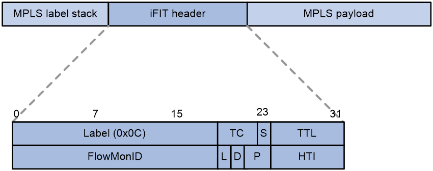
· Label—20 bits in length, same as MPLS label, using a fixed reserved label value of 0x0c for identifying the iFIT header.
· TC—3 bits in length, same as MPLS TC, currently not in use.
· S—1 bit in length, identical to the MPLS S label, set to 1, indicating the bottom of the stack label.
· TTL—8 bits in length, identical to the MPLS TTL.
· FlowMonID—20 bits in length, also known as flow ID in this document, a unique identifier for a target flow, which allows for the identification of an individual target flow.
· L—1 bit in length, loss measurement coloring bit, used to distinguish between packets of two adjacent periods. A value of 1 stands for a colored packet, which belongs to the colored loss measurement period. A value of 0 stands for a non-colored packet that belongs to the non-colored loss measurement period.
· D—1 bit in length, delay measurement marking bit, used to distinguish between target flow packets for delay measurement and ordinary target flow packets. A value of 1 indicates that the packet is used for delay measurement, and the timestamp of the interface receiving the packet needs to be recorded. A value of 0 indicates that the packet is an ordinary target flow packet, and a timestamp does not need to be recorded.
· P—2 bits in length, period marker as follows:
¡ 00—Indicates that the measurement period is 10 seconds.
¡ 01—Indicates the measurement period is 30 seconds.
¡ 10—Indicates that the measurement period is 60 seconds.
¡ 11—Indicates that the measurement period is 300 seconds.
· HTI—Head type identifier, used to identify hop-by-hop and end-to-end statistical scenarios.
¡ 0x00—Reserved.
¡ 0x01—Represents end-to-end measurement.
¡ 0x02—Represents hop-by-hop measurement.
iFIT packet encapsulation format in the SRv6 network
A new Destination Options Header has been added to the SRv6 packet to encapsulate iFIT information, and a new OptionType field has been introduced within it to identify the iFIT header, as shown in Figure 6.
Figure 6 iFIT header encapsulation format in the SRv6 network
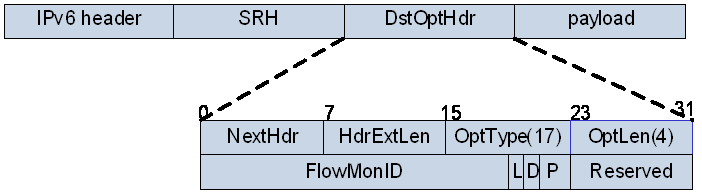
· OptType—8 bits in length, which identifies iFIT type, with a value of 00010001, without changing the routing header.
· OptLen—8 bits in length, representing the length of the iFIT header.
· FlowMonID—Also referred to as flow ID in this document. It consists of 20 bits and is the unique identifier for a target flow.
· L—1 bit in length, loss measurement coloring bit, used to distinguish packets from two adjacent periods. A value of 1 indicates coloring, and all packets in the colored loss measurement period need to be colored. A value of 0 indicates no coloring, and the packet belongs to the non-colored loss measurement period.
· D—1 bit in length, delay measurement coloring bit, used to distinguish between target flow packets for delay measurement and ordinary target flow packets. A value of 1 indicates that the packet is used for delay measurement and needs to be timestamped. A value of 0 indicates that the packet is an ordinary target flow packet and does not need to be timestamped.
· P—2 bits in length, period indicator, including the following options:
¡ 00—Indicates that the measurement period is 10 seconds.
¡ 01—Indicates that the measurement period is 30 seconds.
¡ 10—Indicates that the measurement period is 60 seconds.
¡ 11—Indicates that the measurement period is 300 seconds.
Packet encapsulation format (China Mobile standard format)
|
|
NOTE: In the early stages of iFIT development, draft activity was relatively high, but there were no RFCs. To facilitate iFIT packet interoperability among major manufacturers, China Mobile, H3C, Huawei, and other communication companies jointly developed a set of iFIT enterprise standard (referred to as "Mobile enterprise standards" in this document). These standards defined the iFIT header structure, its placement, and the packet reporting analysis related to iFIT results. In this document, sections with differences in requirements between non-Mobile enterprise standards and Mobile enterprise standards (for example, iFIT header encapsulation) are described separately. Content without a specific Mobile enterprise standard annotation implies that it applies to both non-Mobile enterprise standards and Mobile enterprise standards. |
In order to achieve high-precision performance measurement, while keeping the deployment of the entire statistical system as simple as possible, iFIT introduced the concept of iFIT headers. iFIT adds an iFIT header to the target flow packet at the ingress node, passing information such as FlowMonID and measurement period to intermediary nodes and the egress node, via the iFIT header.
iFIT packet encapsulation format in the MPLS/SR-MPLS network
In the MPLS/SR-MPLS scenario, the iFIT header is encapsulated between the bottom of the MPLS stack and the MPLS payload. The specific location is shown in Figure 7.
Figure 7 iFIT header encapsulation format in the MPLS/SR-MPLS network
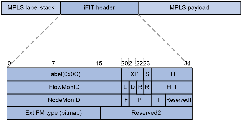
· Label—20 bits in length, same as MPLS label, uses a fixed reserved label value of 0x0c, which is used to identify the iFIT label header.
· TC—3 bits in length, similar to MPLS TC, is currently not in use.
· S—1 bit in length, same as the MPLS S mark, set to 1, indicating the bottom label of the stack.
· TTL—8 bits in length, identical to MPLS (Multiprotocol Label Switching) TTL.
· FlowMonID—20 bits in length, also known as flow ID in this document. It identifies a target flow uniquely and acts as the target flow ID.
· L—1 bit in length, loss measurement coloring bit, used to distinguish packets from two adjacent periods. A value of 1 represents a colored packet, which belongs to the colored loss measurement period. A value of 0 represents an non-colored packet, which belongs to the non-colored loss measurement period.
· D—1 bit in length, the delay measurement coloring bit, is used to distinguish between the target flow packets used for delay measurement and ordinary target flow packets. When the value is 1, it indicates that the packet is used for delay measurement, and the timestamp when the interface receives this packet needs to be recorded. When the value is 0, it indicates that the packet is an ordinary target flow packet, where recording the timestamp is not required.
· R—1 bit in length, reserved field.
· HTI—Identifies the type of the extension header, including the following options:
¡ 0: Reserved.
¡ 1 to 15: Used for private expansion.
¡ 16 to 255: Used for standard expansion. For the iFIT header, the value of this field is 16.
· NodeMonID—20 bits in length, also referred to as device ID in this document, used to uniquely identify a device on the transmit network.
· F: 1 bit in length, used to identify the direction of the service flow. When set to 1, it indicates the necessity of self-learning for the reverse service flow. The egress node triggers the reverse flow detection based on the information of the 5-tuple element from the forward flow.
· P: 3 bits in length, indicating the measurement period, including the following options:
¡ 000: 1s
¡ 001: Indicates that the measurement period is 10 seconds.
¡ 010: Indicates that the measurement period is 30 seconds.
¡ 011: Indicates that the measurement period is 60 seconds.
¡ 100: Indicates that the measurement period is 300 seconds.
¡ Other values: Reserved.
· T: 2 bits in length, used to identify the detection type. The acceptable values are:
¡ 00: Reserved.
¡ 01: Indicates end-to-end measurement.
¡ 10: Indicates hop-by-hop measurement.
¡ 11: Reserved.
· Reserved1: 6 bits in length, reserved field.
· Ext FM type (bitmap): 16 bits in length, used for expansion of flow detection type IDs, identified by bitmap IDs. The values and meanings are temporarily reserved.
· Reserved2: 16 bits in length, reserved field.
iFIT packet encapsulation format in the IPv6 (SRv6/G-SRv6/G-BIER) network
Use DOH to encapsulate the iFIT head
In the IPv6 (SRv6, G-SRv6 and G-BIER) network, iFIT adds a Destination Options Header in the IPv6 packet header to encapsulate iFIT information, and uses the OptionType field (with a value of 16) to identify the iFIT header. In the SRv6, G-SRv6, and G-BIER network groups, the DOH option uses the same field, and the field has the same meaning, as shown in Figure 8. The only difference is the location where the DOH option is placed.
Figure 8 The encapsulation of iFIT headers under the IPv6 networking environment
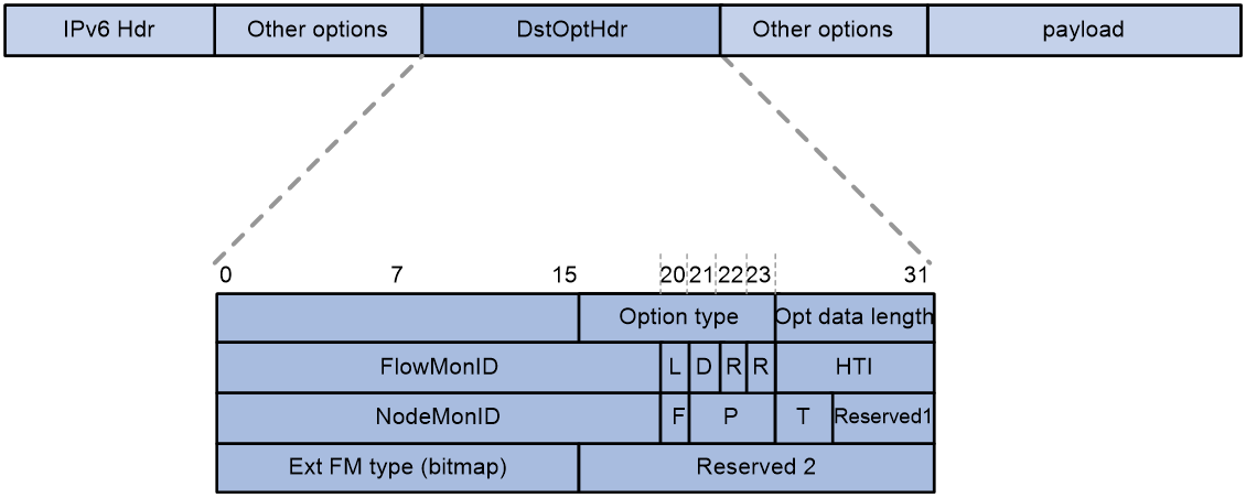
· Option type—8 bits in length, identifies the iFIT type with the value set as 00010001, without changing the routing header.
· Opt data length—8 bits in length, length of the iFIT header.
· For more information about other fields, see "iFIT packet encapsulation format in the MPLS/SR-MPLS network."
iFIT packet encapsulation format in the SRv6/G-SRv6 network
In the SRv6 and G-SRv6 networks, the placement of the DOH option encapsulating iFIT information is the same.
· End-to-end iFIT measurement: Place the DOH option before the SRH option, as shown in Figure 9.
Figure 9 iFIT end-to-end measurement packet encapsulation in the SRv6/G-SRv6 network
![]()
· Hop-by-hop iFIT measurement: The DOH option is placed after the SRH option, as shown in Figure 10.
Figure 10 iFIT hop-by-hop measurement packet encapsulation in the SRv6/G-SRv6 network
![]()
iFIT packet encapsulation format in the G-BIER network
The encapsulation format of the G-BIER packet, from the outermost to the innermost, follows the sequence of IPv6 basic header, DOH encapsulating iFIT information, DOH encapsulating G-BIER header, and the original multicast datagram, as shown in Figure 11.
Figure 11 iFIT packet encapsulation format in the G-BIER network
![]()
Operating mechanism
Time synchronization
iFIT is based on time synchronization. Before the measurement starts, it is required that the time of all devices participating in iFIT measurement is synchronized, ensuring that each device can perform packet statistics and reporting based on the same measurement period. If the time is not synchronized, it will result in inaccurate iFIT calculation results. The time synchronization between the analyzer and iFIT devices does not affect the calculation results, but for easier management and maintenance, it is recommended that the time of the analyzer and all iFIT devices is kept synchronized.
iFIT utilizes the Precision Time Protocol (PTP) for time synchronization.
|
|
NOTE: If iFIT delay measurement is required, the time synchronization precision must be at or above the microsecond level. |
Packet loss measurement mechanism
iFIT packet loss calculation is based on the principle of packet conservation, which applies to the same target flow:
· The total number of packets entering from the ingress node must be equal to the total number of packets transmitted by the egress node in each period. If they are not equal, it indicates that there's packet loss occurring within the target network.
· The number of target packets flowing through any MP must be equal in each period. If they are not equal, it indicates that there is packet loss between these two MPs.
To achieve periodic measurement and ensure accuracy, iFIT alternates the coloring of target packets in adjacent periods by setting the L field in the iFIT header to 1 and 0 alternately. During the coloring period, only the target packets with the L field set to 1 are counted, while in non-coloring period, only those with the L field set to 0 are counted.
The mechanism for iFIT packet coloring and counting is as follows:
· After receiving a packet, the ingress MP will select the target flow according to the configured iFIT matching rules. It will then perform periodic alternate coloring and cycle counting on the target flow, and report the packet count for each cycle to the Analyzer.
· Upon receiving the packet, a transmit MP will select the target flow based on the same iFIT matching rules. It will then perform cycle counting on the target flow and report the packet count to the analyzer on a periodic basis before forwarding it to the next hop.
· Upon receiving the packet, the egress MP will similarly perform cycle counting on the target flow and report the packet count to the analyzer on a periodic basis. Afterwards, it will de-color the target flow and forward it to the next hop.
In order to ensure the accuracy of counting, all MPs will use two counters simultaneously.
· Coloring packet counter: Used for counting the number of colored packets.
· Non-coloring packet counter: Used for counting the number of non-colored packets.
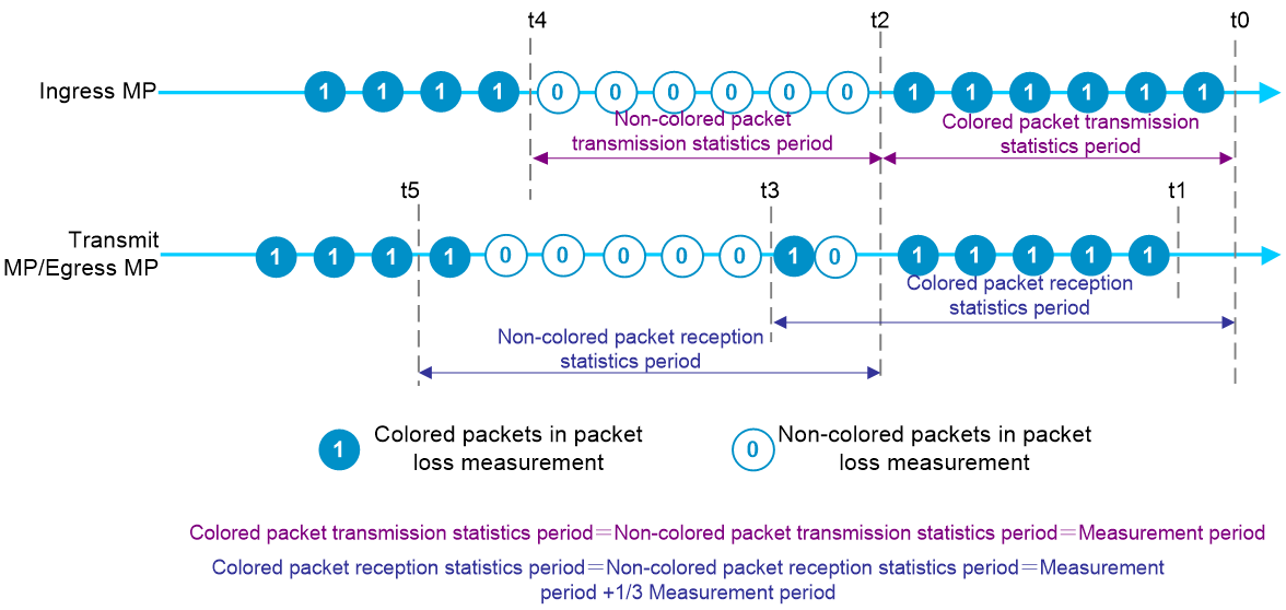
Figure 12 iFIT packet loss measurement
|
|
NOTE: Packet loss measurement and delay measurement are performed simultaneously. For ease of understanding packet loss measurement, only the packet loss measurement coloring bit is marked in Figure 12, while the delay measurement coloring bit is not marked. |
As shown in Figure 12, the process of packet loss measurement for iFIT packets is as follows:
1. t0 moment
a. The MP begins packet coloring, and the coloring packet statistics start to be collected.
b. The transmit MP/egress MP is enabled with the packet coloring counter and starts counting the colored packets.
2. t1 moment
a. The first colored packet arrives at the transmit MP/egress MP from the ingress MP.
b. The transmit MP records the first colored packet.
3. t2 moment
a. The MP completes a period of packet coloring, and reports the counted colored packets to the analyzer. Concurrently, it starts the count of non-colored packets.
b. Enable the non-colored packet counter on the transmit MPs and the egress MP and start counting non-colored packets.
4. t3 moment
The transmit MP/egress MP concludes the counting of colored packets and reports the count to the analyzer. Simultaneously, it starts counting non-colored packets.
Due to network delay, to maximally avoid the adverse effects of network delay and disorder on statistical results, the time at which the transmit/egress MP ends a statistical period is slightly later than the ingress MP t2 (by 1/3 of a measurement period). From t0 to t3 is the period for receiving colored packet statistics. During this section, the colored counter of transmit/egress MP only calculates colored packets, ensuring late arriving colored packets can be counted.
5. t4 moment
a. The ingress MP concludes a cycle of not coloring packets and reports the count of non-colored packets to the analyzer. Meanwhile, it initiates the next round of coloring and counts colored packets.
b. The transmit MP/egress MP also starts the next round of coloring packet counter and counts the colored packets.
6. t5 moment
The transmit MP/egress MP concludes the counting of non-colored packets and reports the count to the analyzer.
During t2 through t5, the non-coloring packet counter counts only non-colored packets, excluding colored packet counts.
7. The analyzer can calculate the packet loss and packet loss rate between any two MPs based on the packet counts reported by each node within each cycle.
¡ The number of lost packages equals the total target packets received by the MP minus the total target packets received by the downstream MP.
¡ Packet loss rate = (Total target packets received by MP – Total target packets received by downstream MP)/Total target packets received by MP
¡ Packet loss = Total target packets received by MP – Total target packets received by downstream MP
¡ Packet loss rate = (Total target packets received by MP – Total target packets received by downstream MP)/Total target packets received by MP
Delay measurement mechanism
The principle of the iFIT delay measurement mechanism is as follows: Each measurement dot matches the target packet based on the iFIT header and periodically records the timestamp of the first packet received in each period. The difference between the timestamps of any two measurement dots is the transmission delay of the target packet between these two dots.
As shown in Figure 13, the process for calculating the iFIT packet delay is as follows:
1. The ingress interface of the ingress node records the time t1 when the first packet was received in the colored packet transmission statistics period.
2. The egress interface of the egress node records the time t2 when the packet is received.
3. The ingress and egress nodes report these two timestamps to the analyzer. The analyzer calculates the delay. Delay[1] = t2 – t1.
4. The ingress interface of the ingress node records the time t3 of the first packet was received in the non-colored packet transmission statistics period.
5. The egress interface of the egress node records the time t4 when the packet is received.
6. The ingress and egress report these two timestamps to the analyzer, which calculates the delay as Delay[2] = t4 – t3. Based on t1, t2, t3, and t4, the analyzer can further calculate the average delay as: (Delay[1] + Delay[2])/2 = [(t2 – t1) + (t4 – t3)]/2, and the delay jitter as: (Delay[2] – Delay[1]) = (t4 – t3) – (t2 – t1).
Figure 13 iFIT delay measurement
Measurement data reporting mechanism
iFIT-enabled devices push the measurement data to the analyzer by using the gRPC protocol.
Currently, only gRPC dial-out mode is supported. In this mode, an iFIT-enabled device act as a gRPC client and the analyzer acts as a gRPC server (also called a gRPC collector in the gRPC protocol). The device establishes a gRPC connection with the analyzer, pushing the subscribed iFIT statistical data to the analyzer.
iFIT workflow
In an end-to-end performance statistics scenario, there is no need to deploy transmit nodes, and the configuration, principle, and hop-by-hop performance statistics of the ingress and egress nodes are the same. Using the hop-by-hop performance statistics scenario as an example, below demonstrates the iFIT workflow.
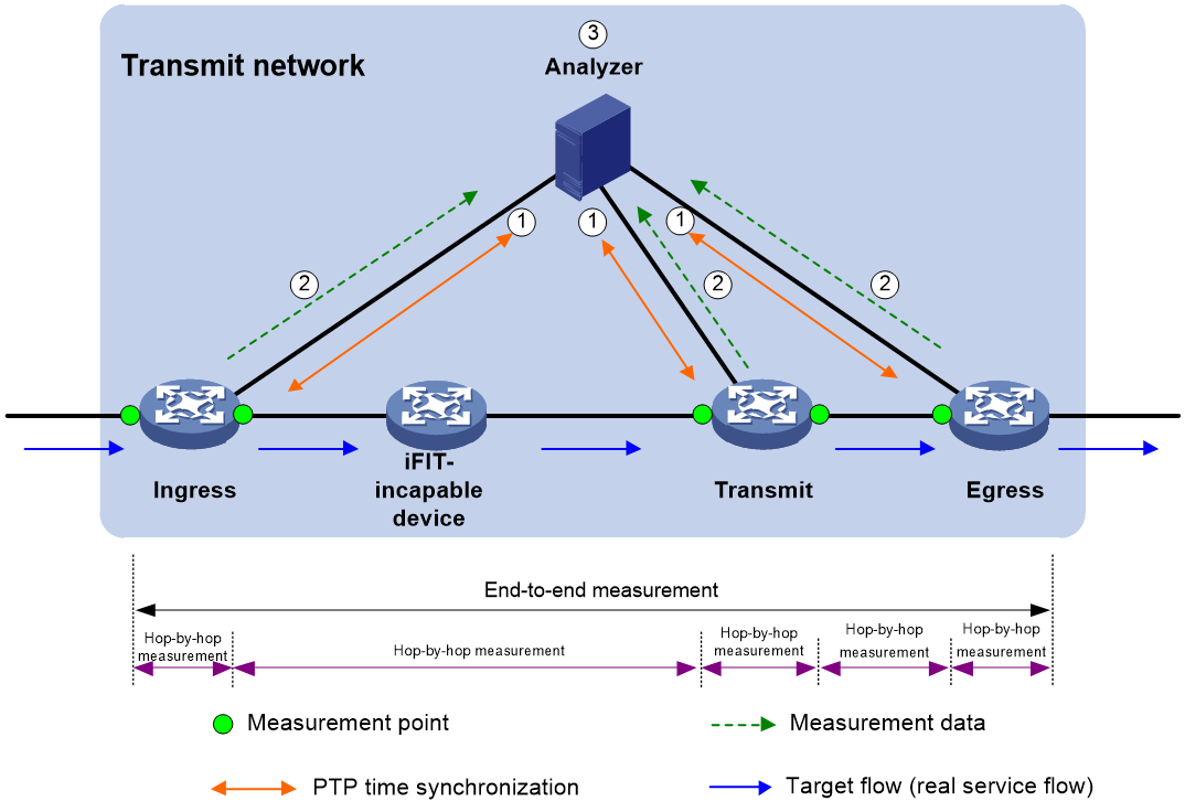
As shown in Figure 14, the transmit network have four devices, three of which support iFIT. After deploying the iFIT function on these three devices. The iFIT workflow is as follows:
1. The analyzer and all iFIT devices synchronize time using the PTP protocol.
2. The iFIT processing is carried out on the packets of target flow by the iFIT device.
a. The ingress node parses the packet flow through the ingress interface, identifies the target flow, adds an iFIT packet header to the target flow packet, records the arrival time of the first packet in each statistical cycle, and counts the number of target flow packets received in each cycle. Then, it reports packet counts and timestamp information to the analyzer through the gRPC connection on a cyclical basis.
b. For packets containing iFIT headers, on the transmit interface of the target transmit network (on iFIT-capable devices in the transmit network, ingress and egress interfaces of the target flow), the device records the arrival time of the first packet in each statistical period and count the number of target flow packets received in each cycle. Then, the device reports packet counts and timestamp information to the analyzer through the gRPC connection on a period basis.
c. For packets containing iFIT headers, on the egress interface of the transmit network (where the target flow leaves the target network), the device records the arrival time of the first packet in each statistical period and count the number of target flow packets received in each period. Then, the device reports packet counts and timestamp information to the analyzer through the gRPC connection on a period basis. Finally, remove the iFIT packet header from the target flow packets and continue forwarding.
3. The analyzer performs packet loss analysis on the same period and the same target flow, and calculates the time delay.
Figure 14 iFIT operating mechanism
|
|
NOTE: The egress interface of the transmit network refers to the interface from which the target flow leaves the transmit network. It could potentially be the ingress interface for the target flow on the egress node, or the egress interface of the target flow. Whether it's an ingress or egress interface depends on the device mode. |
Typical network applications
Performing iFIT measurement on the MPLS L3VPN HoVPN network
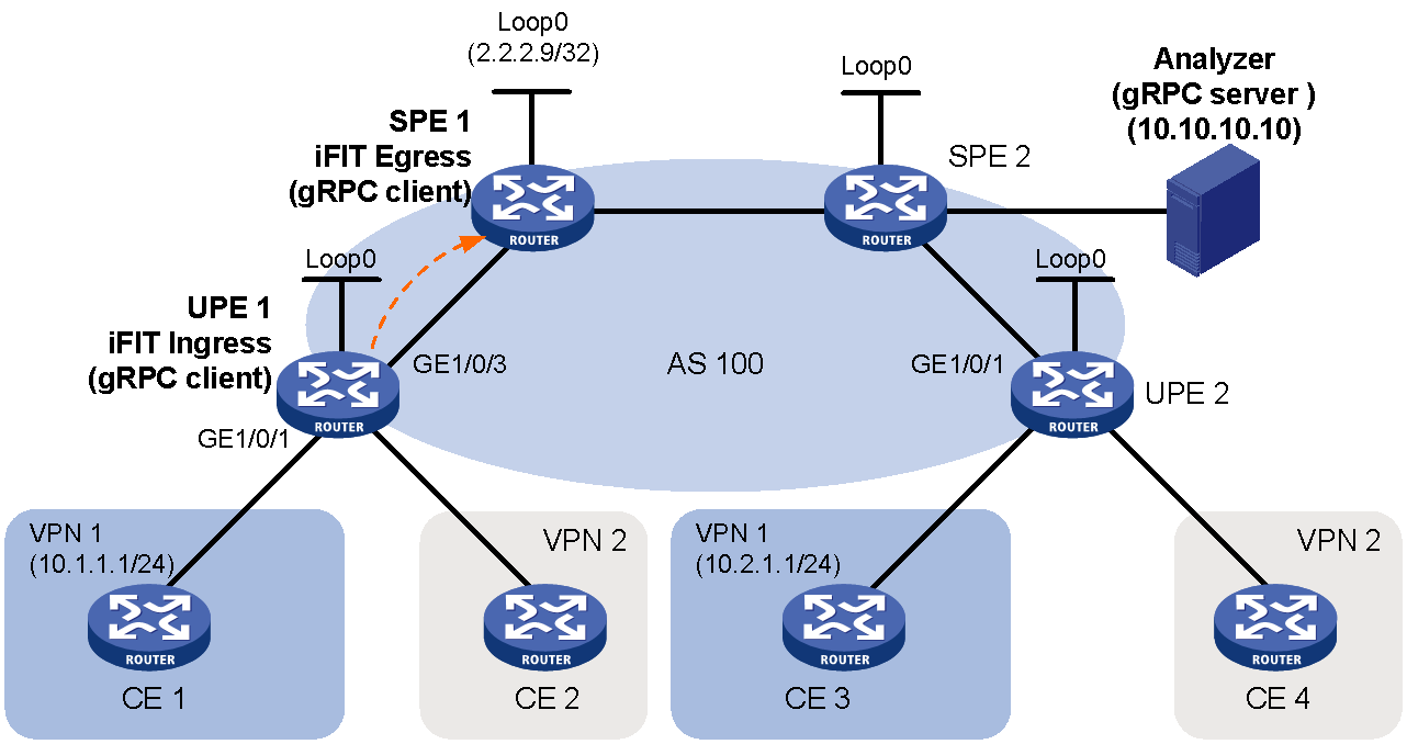
In the MPLS VPN network shown in Figure 15:
· The SPE, as a PE device in the provincial network, connects to the MPLS VPN network of the city.
· As a PE device for lower level municipal networks, UPE accesses VPN clients, and the performance requirements for UPE are lower than those for SPE.
· SPE uses a routing policy to restrict the access rights between different sites, enabling CE 1 and CE 3 within VPN 1 to access each other, while CE 2 and CE 4 within VPN 2 cannot.
· Deploying the iFIT function on UPE 1 and SPE 1 enables the measurement of whether there is any packet loss and what the delay is when traffic from CE 1 to CE 2 in VPN 1 traverses the HoVPN network.
Performing iFIT measurement on the L3VPN over SRv6 network
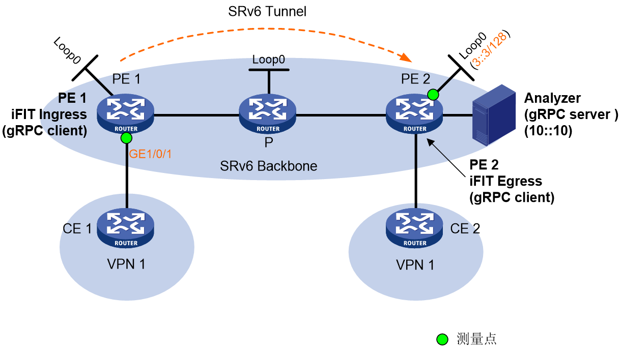
As shown in Figure 16, the core network is an IPv6 network, and the private network is an IPv4 network. MPLS L3VPN over SRv6 BE is deployed between PE devices in the IPv6 network, and VPNv4 data is passed through the SRv6 tunnel.
· Configure EBGP between CE and PE to exchange VPN route information.
· Devices within the same autonomous system (AS) run IS-IS to achieve IPv6 network interoperability, and configure MP-IBGP to switch VPNv4 route information.
· Deploy the iFIT function on PE 1 and PE 2. This enables traffic measurements within the SRv6 tunnel between PE 1 and PE 2 to determine if any packages are lost and to evaluate the delay time.
Figure 16 Measure the L3VPN over SRv6 network group topology with iFIT
References
· RFC 7799: Active and Passive Metrics and Methods
· RFC 8321: Alternate-Marking Method for Passive and Hybrid Performance Monitoring draft-ietf-6man-ipv6-alt-mark-02
