- Released At: 17-04-2024
- Page Views:
- Downloads:
- Table of Contents
- Related Documents
-
VXLAN Technology White Paper
Copyright © 2024 New H3C Technologies Co., Ltd. All rights reserved.
No part of this manual may be reproduced or transmitted in any form or by any means without prior written consent of New H3C Technologies Co., Ltd.
Except for the trademarks of New H3C Technologies Co., Ltd., any trademarks that may be mentioned in this document are the property of their respective owners.
The content in this text is general technical information, and some information may not be applicable to the product you purchased.
Contents
Establishing a VXLAN tunnel and associating it with a VXLAN
Assignment of traffic to VXLANs
Centralized VXLAN IP gateway group
Technical features implemented by Comware
VXLAN Layer 2 interconnect network
Centralized VXLAN IP gateway network
Distributed VXLAN IP gateway network
VXLAN collaboration with the SDN controller for network configuration
Overview
Technical background
With the rapid development of virtualization technology, the scale of data centers is continuously expanding, and the number of data center tenants and VMs is growing explosively. Traditional Layer 2 networks face significant challenges.
· Insufficient VLAN resources
The traditional Layer 2 network isolation technical VLAN, because its identify (ID) that isolates each virtual Layer 2 network's tag field only has 12 bits, can only divide into 4096 isolated virtual Layer 2 networks. This falls far short of the requirement to isolate a large number of tenants in a large Layer 2 network.
· Cloud host migration
To flexibly allocate network services and resources, VM migrations across devices and even data centers are increasingly frequent. To ensure service continuity during the migration process, the IP and MAC addresses of the VMs need to remain unchanged. However, traditional network technologies cannot maintain the same IP and MAC addresses before and after the migration.
Meanwhile, with the deployment of multiple data centers, requirements such as the migration of VMs across data centers, disaster recovery, and load sharing across data centers have necessitated that the expansion of the Layer 2 network not only stop at the boundaries of the data center, but also consider crossing the zone of data center rooms, extending to the local backup center and remote disaster recovery center. Generally, multiple data centers are connected through routing, naturally forming a Layer 3 network. To achieve the intercommunication of two Layer 2 networks connected through a Layer 3 network, it is necessary to implement L2 over L3.
Virtual eXtensible LAN (VXLAN) is a Layer 2 VPN technology that uses a MAC in UDP encapsulation based on an IP network. VXLAN can provide Layer 2 interconnectivity for dispersed physical sites based on existing ISP or enterprise IP networks, also offering service separation for different tenants. VXLAN is primarily used in data center networks and campus access networks.
Benefits
· Supports a large number of tenants: By using a 24-bit identifier (ID), up to 2 to the 24th power (16777216) VXLANs can be supported, greatly increasing the number of tenants supported. This resolves the issue of insufficient VLAN resources in traditional two-layer networks.
· VM migration with unchanged IP and MAC: Utilizing the encapsulation method of MAC in UDP, it facilitates the transparent transmission for original Layer 2 packets within the IP network, ensuring that both IP and MAC remain the same before and after the migration of the VM.
· Easy to maintain: Building large Layer 2 networks based on an IP network makes network deployment and maintenance easier. It also allows for full exploitation of existing IP network technology, such as utilizing equal cost routes for load sharing. Only edge devices in the IP transport network need to undertake VXLAN processing. The intermediate devices in the network only need to forward packets according to the IP header, reducing the difficulty and cost of network deployment.
VXLAN implementation
Network model
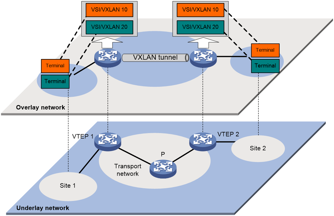
As shown in Figure 1, the typical network model of VXLAN includes the following components:
· User endpoint (endpoint): A user endpoint can be a PC, wireless endpoint, or a VM created on a server. Different user endpoints can belong to different VXLANs. User endpoints that belong to the same VXLAN are in the same logic Layer 2 network and can interact at Layer 2. User endpoints that belong to different VXLANs are isolated at Layer 2.
|
|
NOTE: The operation of VXLAN is explained in this document by using VMs as an example, unless otherwise specified. When other types of user endpoints are used, the operation of VXLAN is the same as that with VM and will not be reiterated. |
· VXLAN Tunnel End Point (VTEP): This is an edge device for VXLAN. All related VXLAN processing, such as identification of the VXLAN to which an Ethernet frame belongs, Layer 2 forwarding based on VXLAN, encapsulation, decapsulation of packets and so on, occur on the VTEP. A VTEP can be a standalone physical device or a server hosting a VM. VTEPs support the following roles:
¡ VTEP: A device that only supports the Layer 2 forwarding function of VXLAN, meaning it can only perform Layer 2 forwarding within the same VXLAN.
¡ Gateway: A device capable of performing Layer 3 forwarding across VXLAN or accessing external IP networks. Depending on the deployment method, the gateways include centralized gateways and distributed gateways.
· VXLAN tunnel: A point-to-point logical tunnel between two VTEPs. The VTEP encapsulates the data frame with a VXLAN header, UDP header, and IP header, and then sends the encapsulated packet through the VXLAN tunnel to the remote VTEP. The remote VTEP then performs decapsulation.
· Core device: This refers to the devices in the IP transport network, such as the P device in Figure 1. Core devices do not participate in EVPN processing, and they only need to perform Layer 3 forwarding based on the outer destination IP address of the encapsulated packet.
· VXLAN network: The customer network might include user endpoints within multiple sites located in different geographical areas. These sites can be connected by using VXLAN tunnels on the backbone network, creating a logical Layer 2 VPN for users. This Layer 2 VPN is known as a VXLAN network. VXLAN networks are identified by VXLAN ID, also known as VXLAN Network Identifier (VNI), which is 24 bits long. User endpoints in different VXLAN networks cannot intercommunicate at Layer 2.
· Virtual switch instance (VSI): A virtual switch on a VTEP that provides Layer 2 switching services for a VXLAN. The VSI can be considered a virtual Ethernet switch on the VTEP that performs Layer 2 forwarding based on VXLAN. It has all the functions of a traditional Ethernet switch, including source MAC learning, MAC address aging, and flooding. Each VSI corresponds to a single VXLAN.
· VSI interface: As the gateway for VMs within VXLAN, it is used for processing packet forwarding across VXLAN networks. One VXLAN network corresponds to one VSI interface.
VXLAN support for IPv6
VXLAN supports the interconnection of customer network and transport network when they are IPv6 networks. When the customer network or transport network is an IPv6 network, interoperability can be achieved through the deployment of VXLAN.
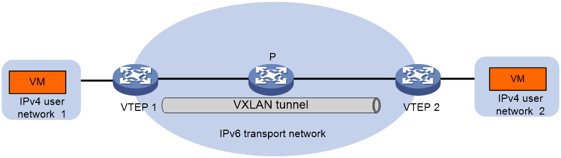
As shown in Figure 2, if the transport network has been upgraded to an IPv6 network and the customer network is still an IPv4 network, an IPv6 VXLAN tunnel can be established between VTEPs to enable communication between the IPv4 customer network and the IPv6 network.
Figure 2 Schematic diagram of IPv4 over IPv6 VXLAN network
As shown in Figure 3, if the customer network has been upgraded to an IPv6 network and the transport network is still an IPv4 network, communication between the IPv6 customer network and the IPv4 network can be accomplished by establishing an IPv4 VXLAN tunnel between VTEPs.
Figure 3 Schematic diagram of IPv6 over IPv4 VXLAN network

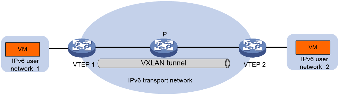
As shown in Figure 4, if both the customer network and transport network have been upgraded to IPv6 network, establishing an IPv6 VXLAN tunnel between the VTEPs can facilitate the interconnection of IPv6 customer networks.
Figure 4 Schematic diagram of IPv6 over IPv6 VXLAN network
Packet encapsulation format
Figure 5 VXLAN packet encapsulation
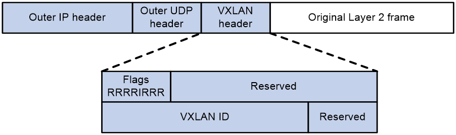
As shown in Figure 5, the encapsulation format of VXLAN packets is as follows: a VXLAN header, UDP header, IP header, and outer Ethernet header are added to the original Layer 2 data frame.
· Outer Ethernet header: It has a length of 14 bytes, or 18 bytes if it includes a VLAN tag. Here, the source MAC is the MAC address of the source VM's affiliated VTEP, and the destination MAC is the MAC address of the next hop device on the path to the destination VTEP.
· Outer IP header: It can be either an IPv4 packet header or an IPv6 packet header. The length of the IPv4 packet header is 20 bytes, and the length of the IPv6 packet header is 40 bytes. The source IP address is the IP address of the VTEP that the source VM belongs to, and the destination IP address is the IP address of the VTEP that the destination VM belongs to.
· Outer UDP packet header: 8 bytes in length. Specifically, the default UDP destination port number is 4789, signifying that the inner encapsulated packet is a VXLAN packet. The UDP source port number is a locally randomly selected value that can be used for multipath load sharing calculations between VTEPs.
· VXLAN header: 8 bytes long and mainly includes the following sections:
¡ When the I indicator in the VXLAN header is set to 1, it means that the VXLAN ID is valid. If it's set to 0, it means the VXLAN ID is invalid. The rest of the bits are reserved and set to 0.
¡ VXLAN ID: Used to identify a VXLAN network, it has a length of 24 bits.
¡ Reserved: The current protocol's reserved bit.
· Original Layer 2 data frame: The raw Ethernet packet transmitted by a VM.
From the encapsulation of the packet, we can see that the VXLAN header and the original Layer 2 data frame exist as the payload of the UDP packet. Network devices between VTEPs only need to forward based on the outer Ethernet header and the outer IP header, and perform load sharing by using the source UDP port number. During this process, the processing of VXLAN packets is completely identical to ordinary IP packets. Therefore, aside from VTEPs, a large number of devices in the current network can support VXLAN networks without needing to be replaced or upgraded.
Operating mechanism
Overview
The operating mechanism of VXLAN can be summarized as:
1. Discover the remote VTEP, establish a VXLAN tunnel between VTEPs, and associate the VXLAN tunnel with VXLAN.
2. Identify the VXLAN to which the received packet belongs, in order to learn the source MAC address of the packet in the corresponding VSI, and forward the packet within that VSI.
3. Learn the MAC address of the endpoint.
4. Forward the packet according to the learned MAC address entry.
Establishing a VXLAN tunnel and associating it with a VXLAN
In order to transmit VXLAN packets to the remote VTEP, it's necessary to create a VXLAN tunnel and associate it with the VXLAN.
Creating a VXLAN tunnel
The following methods are available for setting up a VXLAN tunnel:
· Manual—Manually configure the tunnel interface and specify the source and destination IP addresses of the tunnel as the local and remote VTEP's IP addresses, respectively.
· Automatic—Once the remote VTEP is detected through Ethernet Virtual Private Network (EVPN), a VXLAN tunnel is automatically established between the local VTEP and the remote VTEP.
Associating the VXLAN tunnel with a VXLAN
Two methods are available for associating VXLAN tunnels with VXLANs:
· Manual—Manually associate the VXLAN tunnel with a VXLAN.
· Automatic—The VXLAN tunnel is automatically associated with a VXLAN through the EVPN protocol.
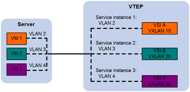
Assignment of traffic to VXLANs
Traffic from the local site to a remote site
The VTEP uses the following methods to assign customer frames to a VXLAN:
· Layer 3 interface-to-VSI mapping—This method maps a site-facing Layer 3 interface to a VSI. The VTEP assigns all frames received from the interface to the VXLAN of the VSI.
· Ethernet service instance-to-VSI mapping—This method uses the frame match criterion of an Ethernet service instance to match a list of VLANs on a site-facing Layer 2 interface. The frame match criterion specifies the characteristics of traffic from the VLANs, such as tagging status and VLAN IDs. The VTEP assigns customer traffic to a VXLAN by mapping the Ethernet service instance to a VSI.
· VLAN-based VXLAN assignment—This method maps a VLAN to a VXLAN. The VTEP assigns all frames of the VLAN to the VXLAN.
After receiving a data frame from a VLAN, Layer 3 interface, or Ethernet service instance, the VTEP determines the associated VXLAN based on the correlated method.
As shown in Figure 6, VM 1 belongs to VLAN 2. An Ethernet service instance 1 matching VLAN 2's packet is configured on the VTEP, binding Ethernet service instance 1 to VSI A, and creating VXLAN 10 within VSI A. Therefore, after the VTEP receives the data frame transmitted by VM 1, it can decide that the data frame belongs to VXLAN 10.
Figure 6 Identification of VXLAN for Layer 2 data frames
Traffic from a remote site to the local site
For VXLAN packets received from the VXLAN tunnel, the VTEP determines the VXLAN to which the packet belongs based on the VXLAN ID carried in the packet.
MAC learning
MAC learning includes local MAC learning and remote MAC learning.
Local MAC learning
Local MAC learning refers to the VTEP's learning of the MAC addresses of the VMs within its local site. Several methods are available for local MAC learning.
· Static configuration—Manually specify the VSI (for example, VXLANI) belonging to the local MAC address and its corresponding Ethernet service instance (for example, AC).
· Dynamic learning of source MAC address through packets—After the VTEP receives the data frame sent by the local VM, it determines the VSI to which the data frame belongs and adds the source MAC address (the MAC address of the VM within the local site) from the data frame to the MAC address table of the VSI. The interface corresponding to this MAC address is the interface that received the data frame.
Remote MAC learning
Remote MAC learning refers to the VTEP's learning of the MAC addresses of VMs within remote sites. Several methods are available for remote MAC learning:
· Static configuration—Manually specify the VSI (i.e. VXLAN) to which the remote MAC address belongs, and its corresponding VXLAN tunnel interface.
· Dynamic learning from the source MAC in the packet—Upon receiving a VXLAN packet sent by the remote VTEP over the VXLAN tunnel, the VTEP determines the VXLAN to which the packet belongs based on the VXLAN ID. It performs decapsulation on the packet, restoring the Layer 2 data frame, and adds the source MAC in the data frame (the MAC of the VM within the remote site) to the MAC address table of the corresponding VSI of the VXLAN. The interface corresponding to this MAC address is the VXLAN tunnel interface.
· Learn through BGP EVPN—Run BGP EVPN on the VTEP, and pass the local MAC address and its corresponding VXLAN information to the remote VTEP through BGP EVPN. Once the remote VTEP receives this information, it adds a MAC address entry in the MAC address table of the VXLAN's corresponding VSI, with the associated interface being the VXLAN tunnel interface.
· OpenFlow controller—Sends remote MAC address entries to VTEPs in the form of flow tables through OpenFlow.
· OVSDB—The controller issues remote MAC address entries to the VTEP through the OVSDB protocol.
The following shows the priority order of different types of remote MAC address entries:
1. Static MAC address entries, and MAC address entries issued by a remote controller through OpenFlow or OVSDB. These types of entries have the same priority and overwrite each other.
2. MAC address entries advertised through VXLAN IS-IS or BGP EVPN. The two types of entries have the same priority and overwrite each other.
3. Dynamic MAC address entries.
Forwarding unicast traffic
After completing local and remote MAC learning, the VTEP forwards unicast traffic within the VXLAN as follows.
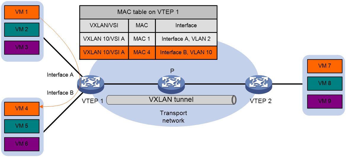
Intra-site unicast forwarding
The VTEP uses the following process to forward a known unicast frame within a site:
1. Identifies the VSI of the frame.
2. Looks up the destination MAC address in the VSI's MAC address table for the outgoing interface.
3. Sends the frame out of the matching outgoing interface.
As shown in Figure 7, when VM 1 (with MAC address MAC 1) transmits an Ethernet frame to VM 4 (with MAC address MAC 4), VTEP 1 receives the Ethernet frame from Interface A. It determines that this data frame belongs to VSI A (VXLAN 10), looks up the MAC address table of VSI A, and finds that the outgoing interface for MAC 4 is Interface B, which is in VLAN 10. Then, it transmits the Ethernet frame to VM 4 within VLAN 10 through Interface B.
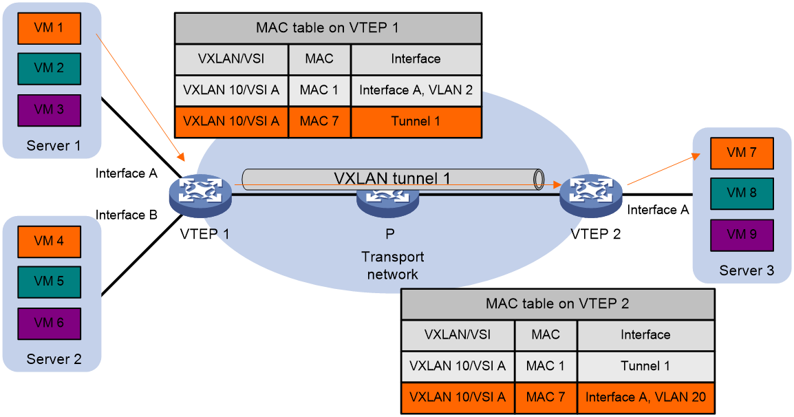
Inter-site unicast forwarding
As shown in Figure 8, using an example of VM 1 (with MAC address MAC 1) transmitting an Ethernet frame to VM 7 (with MAC address MAC 7), the process of forwarding unicast traffic between sites is as follows:
1. VM 1 transmits an Ethernet data frame to VM 7, with the source MAC being MAC 1, the target MAC being MAC 7, and the VLAN ID being 2.
2. After receiving the data frame from Interface A (residing in VLAN 2), VTEP 1 determines that the data frame belongs to VSI A (VXLAN 10), searches the MAC address table of VSI A, and finds that the output port for MAC 7 is Tunnel1.
3. VTEP 1 encapsulates the data frame with a VXLAN header, UDP header, and IP header, then transmits the encapsulated packet through VXLAN tunnel Tunnel1 and sends it to VTEP 2 through the P device.
4. After receiving a packet, VTEP 2 determines that the packet belongs to VXLAN 10 based on the VXLAN ID in the packet, and then it strips the VXLAN, UDP, and IP headers to restore the original data frame.
5. VTEP 2 retrieves the MAC address table for VSI A corresponding to VXLAN 10 and finds that the output port for MAC 7 is Interface A (in VLAN 20).
6. VTEP 2 transmits data frames to VM 7 from VLAN 20 within Interface A.
Forwarding flood traffic
After receiving the flooding traffic (multicast, broadcast, and unknown unicast traffic) from the local site, the VTEP forwards it to all local interfaces and VXLAN tunnels, excluding the receiving interface. To avoid a loop, the VTEP, after receiving a packet from the VXLAN tunnel, will not flood it to other VXLAN tunnels, but only forward it to all local interfaces.
Depending on the replication method, the traffic flooding modes include unicast method (head-end replication), multicast method (tandem replication), and flood proxy method (proxy server replication).
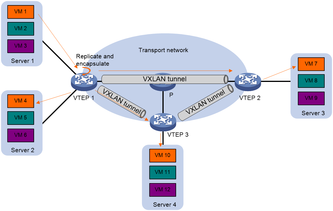
Unicast mode (head-end replication)
As shown in Figure 9, the VTEP is responsible for replicating packets and uses unicast to transmit the replicated packets to the local site through the local interface. Furthermore, it transmits to all remote VTEPs within the VXLAN through the VXLAN tunnel.
Figure 9 Unicast mode
Multicast mode (tandem replication)
|
|
NOTE: The transport network, when operating as an IPv6 network, does not support the multicast method for forwarding flooding traffic. |
In the DC network, when many sites need to interconnect through the IP transport network at Layer 2, using multicast routing can save the use of bandwidth resources of the transport network by reducing flooding traffic.
As shown in Figure 10, under the multicast mode, all VTEPs within the same VXLAN join the same multicast group and use the multicast routing protocol (such as PIM) to establish a multicast forwarding table entry for this group on the IP transport network. When the VTEP receives flooding traffic, it not only floods within the local site, but also encapsulates the multicast destination IP address. The encapsulated packets are then forwarded to the remote VTEP according to the established multicast forwarding table entry.
Figure 10 Schematic diagram for multicast route forwarding

Flood proxy method (proxy server replication)
When many sites in the DC network need to be interconnected through the IP transport network at Layer 2, the use of flood proxy method can save the bandwidth resources of the transport network occupied by flooding traffic, without the participation of multicast protocols.
As shown in Figure 11, in the flood proxy mode, all VTEPs within the same VXLAN establish tunnels manually with the proxy server. After the VTEP receives the flooding traffic, it not only spreads it within the local site, but also transmits it to the proxy server, which then forwards it to the other remote VTEPs.
Figure 11 Schematic diagram for flood proxy method forwarding
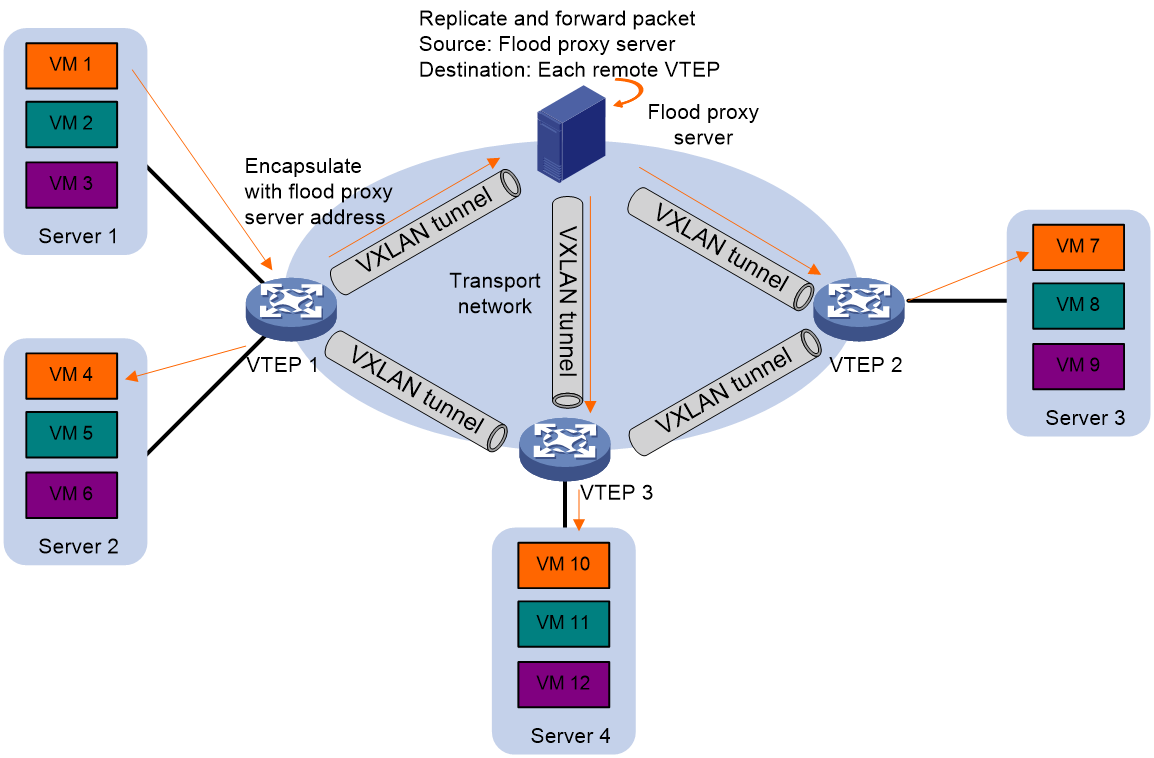
The use of flood proxy is currently predominant in SDN networks, using virtual servers as flood proxy servers. When employing the flood proxy method, follow these restrictions and guidelines:
· The function of automatic learning of remote MAC addresses is disabled on the VTEP, and the MAC address entry deployed by the SDN controller is used for traffic forwarding.
· The function of checking the match between incoming interface and static MAC address entry needs to be disabled on the network side interface of the VTEP. When the VTEP is an IRF fabric, this function also needs to be disabled on the IRF ports interconnecting the member devices.
ARP/ND flood suppression
To avoid consuming transport network bandwidth with the broadcast of ARP requests or the multicasting of ND request packets, the VTEP establishes an ARP/ND flood suppression entry locally after receiving ARP/ND requests and replies either from the local site or through the VXLAN tunnel. Subsequently, when VTEP receives an ARP/ND request from a VM within the site requesting another VM's MAC address, it prioritizes responding according to the ARP/ND flood suppression entry. If there is no corresponding entry, the ARP/ND request is flooded to the transport network. The ARP/ND flood suppression function can significantly reduce the number of ARP/ND floodings.
Figure 12 Diagram for ARP flood suppression
As shown in Figure 12, as for ARP, the process of flood suppression is as follows:
1. VM 1 sends an ARP request to obtain the MAC address of VM 7.
2. VTEP 1 establishes an ARP flood suppression entry for VM 1 based on the received ARP request, and floods the ARP request within VXLAN. (For example, it uses unicast route flooding, as shown in Figure 12).
3. The remote VTEPs (VTEP 2 and VTEP 3) decapsulate the VXLAN packet to obtain the original ARP request packet. After that, they establish an ARP flood suppression entry for VM 1 and flood this ARP request within the designated VXLAN at the local site.
4. Upon receiving the ARP request, VM 7 responds with an ARP reply packet.
5. After receiving the ARP reply, VTEP 2 establishes an ARP flood suppression entry for VM 7, and transmits the ARP reply to VTEP 1 through the VXLAN tunnel.
6. VTEP 1 decapsulates the VXLAN packet to fetch the original ARP reply. Based on this reply, it creates an ARP flood suppression entry for VM 7. Subsequently, the ARP reply packet is transmitted to VM 1.
7. After establishing an ARP flood suppression entry on VTEP 1, the VM 4 sends an ARP request to obtain the MAC address of VM 1 or VM 7.
8. After receiving the ARP request, VTEP 1 establishes the ARP flood suppression entry for VM 4, searches the local ARP flood suppression entry, and responds with an ARP reply packet based on the existing entries, without flooding the ARP request.
9. After establishing an ARP flood suppression entry on VTEP 3, VM 10 transmits an ARP request to obtain the MAC address of VM 1.
10. After receiving the ARP request, VTEP 3 establishes the ARP flood suppression entry for VM 10, searches for local ARP flood suppression entries, responds to the ARP reply packet based on the existing entries, and will not flood the ARP request.
VXLAN IP gateways
VXLAN can provide Layer 2 interconnection for dispersed physical sites. To provide Layer 3 services to VMs within a VXLAN site, you must deploy a VXLAN IP gateway in the network. This allows VMs within the site to communicate with the external network or other VMs in other VXLAN networks through the VXLAN IP gateway. The VXLAN IP gateway can either be deployed on an independent physical device or on a VTEP. When deployed on a VTEP, two kinds of VXLAN IP gateway deployments are supported: centralized VXLAN IP gateway and distributed VXLAN IP gateway.
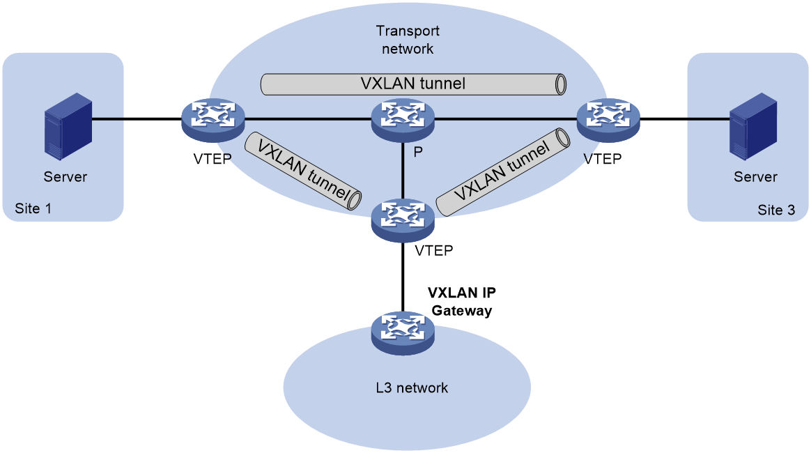
Standalone VXLAN IP gateway
As shown in Figure 13, when the VXLAN IP gateway is deployed on a standalone physical device, it serves as a physical site accessing VTEP, making the VXLAN operation transparent to the gateway device. When a VM communicates with nodes in a Layer 3 network through the VXLAN IP gateway, it encapsulates Layer 3 packets into Layer 2 data frames and transmits them to the VXLAN IP gateway. The VTEP then performs VXLAN encapsulation on this data frame, and forwards it over the IP transport network to the remote VTEP (the VTEP connected to the VXLAN IP gateway). The remote VTEP decapsulates the VXLAN packet and forwards the original Layer 2 data frame to the VXLAN IP gateway. After removing the link layer encapsulation, the VXLAN IP gateway forwards the packet on Layer 3.
Figure 13 Standalone VXLAN IP gateway schematic diagram
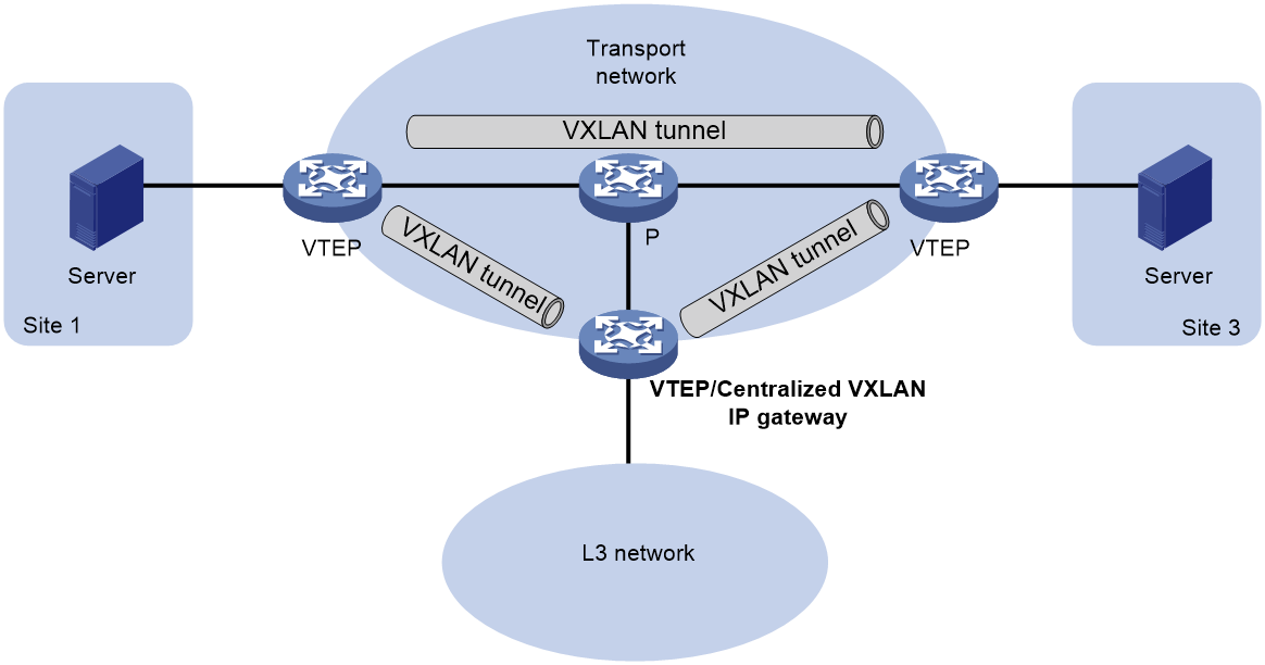
Centralized VXLAN IP gateway
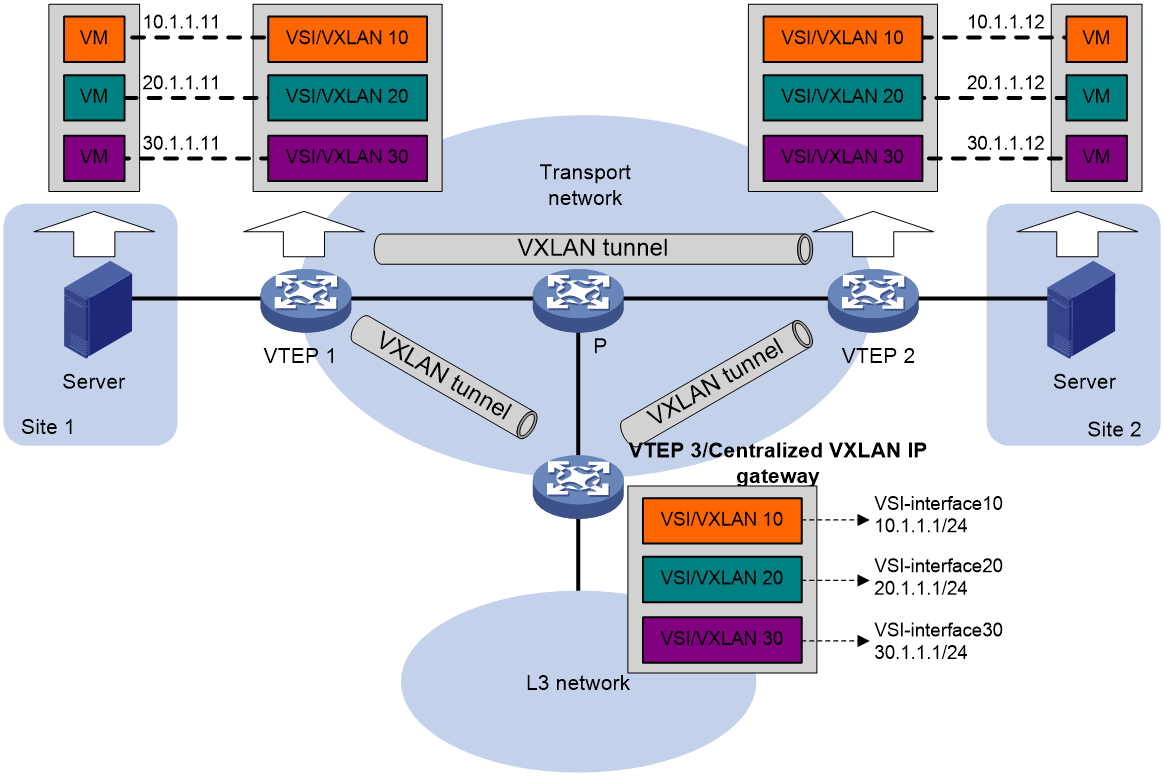
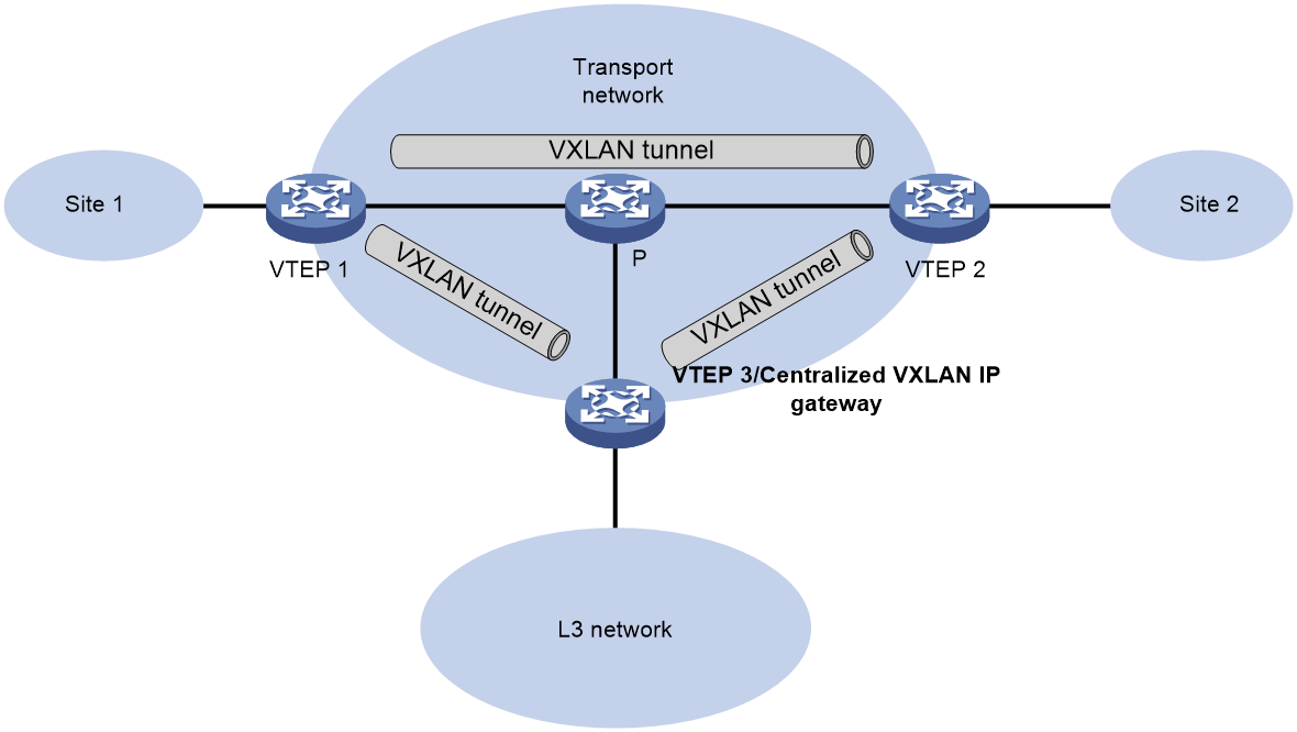
As shown in Figure 14, the centralized VXLAN IP gateway not only terminates Layer 2 VXLAN services but also processes Layer 3 forwarding for encapsulated IP packets. Compared to a standalone VXLAN IP gateway, this method not only saves device resources but also delegates the function of the VXLAN IP gateway to the corresponding Layer 3 virtual interface (VSI interface), making the deployment and control of Layer 3 services more flexible and convenient.
Figure 14 Schematic diagram of centralized VXLAN IP gateway
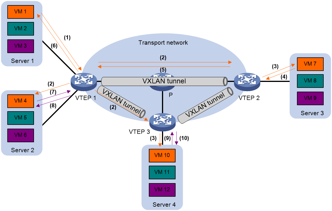
As demonstrated in Figure 15, take the VM with an address of 10.1.1.11 as an example. The process of the VM communicating with the external network at Layer 3 is as follows:
1. When a VM (10.1.1.11) communicates across network segments at the Layer 3, it first broadcasts an ARP request packet to resolve the MAC address of the VXLAN IP gateway (10.1.1.1).
2. After receiving the ARP request packet, VTEP 1 adds VXLAN encapsulation and transmits it to all remote VTEPs.
3. After VTEP 3 decapsulates the VXLAN packet, it finds that the target IP of the ARP request is the local gateway IP address corresponding to VXLAN, which is the IP address of the associated VSI interface of the VXLAN. It then learns the ARP information of 10.1.1.11 and responds to the VM with an ARP reply packet.
4. After receiving the ARP reply packet, VTEP 1 forwards this packet to the VM.
5. After obtaining the MAC address of the gateway, the VM adds the gateway's MAC address to the Layer 3 packet and transmits the Layer 2 data frame to VTEP 3 through the VXLAN network.
6. VTEP 3 performs decapsulation of VXLAN packets, and after removing the link layer header, it carries out Layer 3 forwarding of the encapsulated IP packets, transmitting them to the final destination node.
7. After the packet replied by the destination node arrives at the gateway, the gateway encapsulates the link layer header for the packet according to the ARP entry it has learned, and transmits it to the VM through the VXLAN network.
Figure 15 Layer 3 communication process of a centralized VXLAN IP gateway
The communication process between VMs belonging to different VXLAN networks is similar to the process above. The difference is that a centralized gateway of a VXLAN network needs to forward the packet to another centralized gateway of a VXLAN network. This centralized gateway then forwards the packet to the corresponding VM within its own VXLAN network.
Centralized VXLAN IP gateway group
With a centralized VXLAN IP gateway function performed by a single device, there is a high usage of the device's processing resources within the site filled with many VMs. Furthermore, there is no protection against single point gateway failures. By using a centralized VXLAN IP gateway group, multiple devices can share the gateway function. This provides protection against single point failures and enables load sharing of upstream and downstream traffic.
Figure 16 Schematic diagram of centralized VXLAN IP gateway group
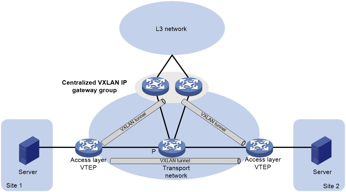
As shown in Figure 16, two centralized VXLAN IP gateways form a group, with identical VTEP IP addresses present on both devices, referred as the VTEP IP of the group. The access layer VTEP establishes a VXLAN tunnel with the VTEP IP of the group, forwarding the packets sent by the VM to other networks to the group. Both gateway devices in the group can receive and process traffic sent by the VM to other networks.
On the access layer VTEP, this VTEP will automatically establish a VXLAN tunnel with the IP address of each member VTEP in the group. Flooding traffic (multicast, broadcast and unknown unicast) is passed through this tunnel to all member VTEPs, ensuring consistent entry information on each member VTEP.
Distributed VXLAN IP gateway
Introduction
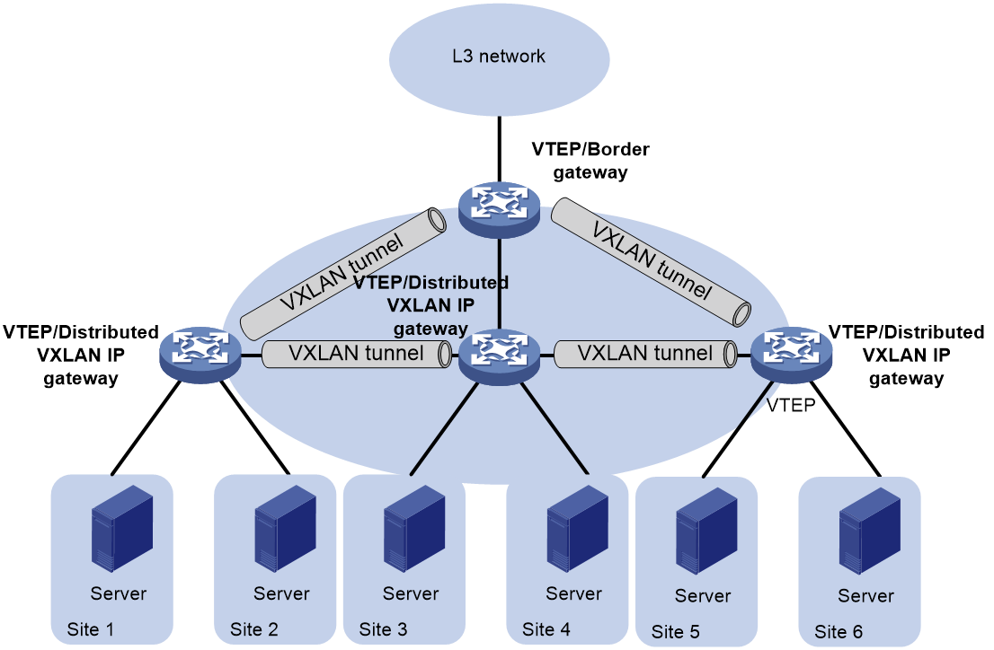
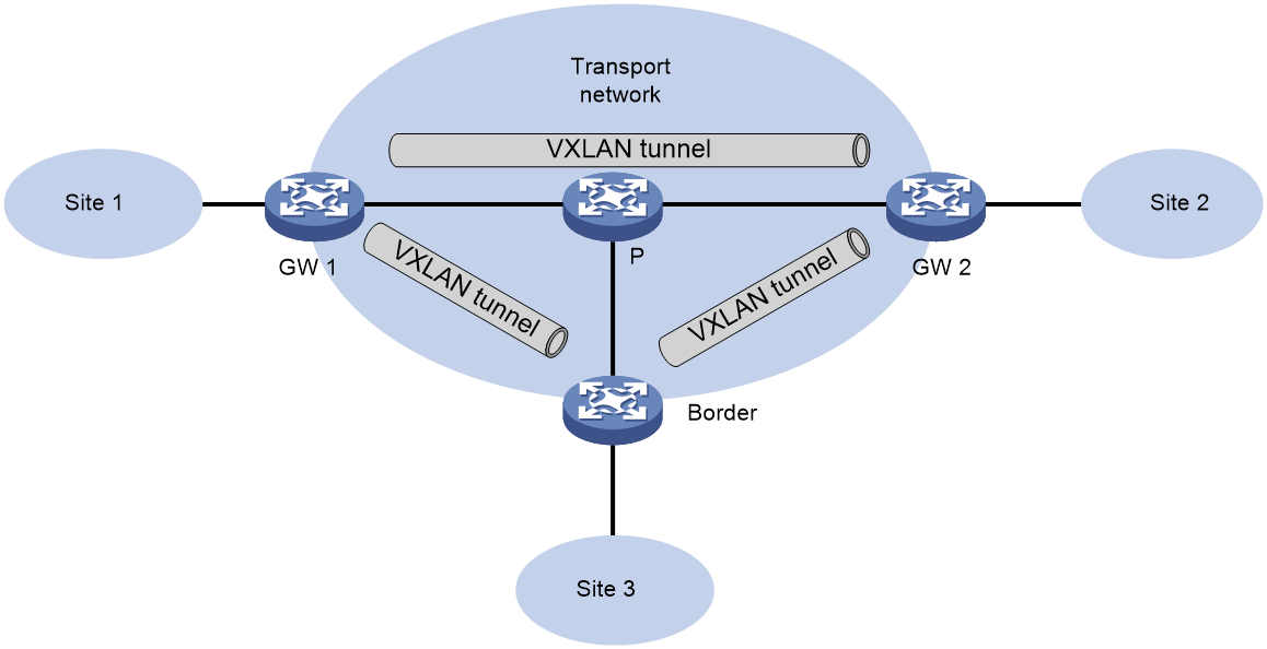
When using a centralized VXLAN IP gateway solution, all traffic between different VXLANs, as well as traffic accessing the external network from VXLAN, is processed by the centralized VXLAN IP gateway. This puts significant pressure on the gateway and exacerbates the consumption of network bandwidth resources. As shown in Figure 17, in a distributed VXLAN IP gateway solution, each VTEP can act as a VXLAN IP gateway, forwarding Layer 3 traffic for local sites, effectively relieving pressure on the gateway.
Figure 17 Distributed VXLAN IP gateway diagram
As shown in Figure 18, in the distributed VXLAN IP gateway network, a VSI interface needs to be created on all distributed VXLAN IP gateways, and the same IP address should be configured for the same VSI interfaces on different gateways, serving as the gateway address for VMs within the VXLAN. A VSI interface also needs to be created on the border gateway (Border) and an IP address should be configured. Additionally, one of the following functions must be enabled on the distributed VXLAN IP gateway:
· ARP/ND flood suppression: After enabling this feature, Layer 2 traffic forwards by looking up the MAC address table, while Layer 3 traffic forwards by looking up the ARP/ND entry.
· Local proxy ARP or local ND proxy: Once this function is enabled, all traffic will pass by searching the ARP entry or ND entry for Layer 3 forwarding. This function will be taken as an example in the following text, to illustrate the communication process in the distributed VXLAN IP gateway.
The gateway can generate ARP entries and ND entries in several ways. The following section will discuss the communication process in a distributed VXLAN IP gateway, based on the dynamic learning of entries through the ARP and ND protocols.
Figure 18 Schematic diagram of distributed VXLAN IP gateway deployment
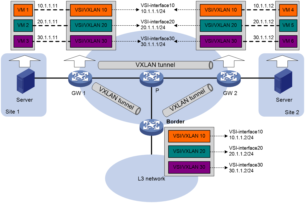
Communication process between VMs at different sites within the same VXLAN
As shown in Figure 18, taking VM 1's access to VM 4 as an example, the communication process of VMs at different sites within the same VXLAN is as follows:
1. VM 1 broadcasts an ARP request packet to obtain the MAC address of VM 4.
2. After receiving the ARP request packet from gateway 1, the ARP information from VM 1 is learned and the ARP request is responded to by proxy. Specifically, an ARP reply packet is transmitted to VM 1, with the MAC address in the reply being that of the VSI interface 10.
3. VM 1 has learned that the MAC address of VM 4 is the same as the MAC address of VSI interface 10 on gateway 1.
4. Gateway 1 will modify the source MAC address in the received ARP request packet to the MAC address of VSI interface 10, and broadcast this ARP request to local and remote sites within VXLAN 10.
5. After decapsulating the VXLAN packet, gateway 2 learns VM 1's ARP information (IP is 10.1.1.11, MAC is the MAC of VSI interface 10 on gateway 1, and outgoing interface is the tunnel interface that receives this VXLAN packet), modifies the source MAC in the ARP request packet to the MAC address of local VSI interface 10, and then broadcasts within the local site of VXLAN 10.
6. Upon receiving an ARP request, VM 4 learns VM 1's ARP information (with an IP of 10.1.1.11 and a MAC on gateway 2's VSI interface 10) and transmits an ARP reply packet to the local gateway 2.
7. Upon receiving the ARP reply packet from VM 4, gateway 2 learns the ARP information of VM 4, modifies the source MAC in the ARP reply packet to the MAC address of the local VSI interface 10, and according to the already learned ARP entry, adds VXLAN encapsulation to the ARP reply packet before transmitting it to gateway 1.
8. After decapsulating the VXLAN packet, gateway 1 learns the ARP information of VM 4 (IP is 10.1.1.12, MAC is the MAC of VSI interface 10 on gateway 2, outgoing interface is the Tunnel interface that received this VXLAN packet) according to the received ARP reply packet.
9. Upon completion of the ARP information study through the above steps, VM 1 transmits a packet to VM 4, which is forwarded based on the learned ARP information: Initially, it is transmitted to gateway 1; gateway 1 performs a VXLAN encapsulation and then transmits it to gateway 2; after gateway 2 decapsulation, it is transmitted to VM 4.
Communication process between VMs at different sites within different VXLANs
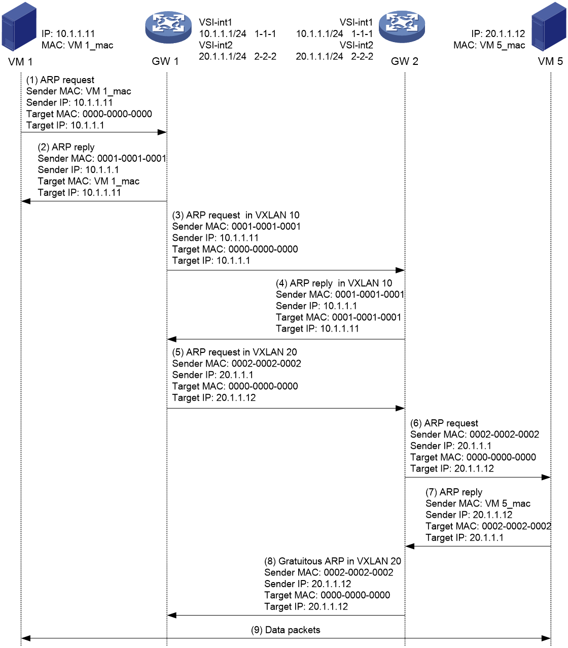
As shown in Figure 19, take the example of VM 1 (VXLAN 10) accessing VM 5 (VXLAN 20). The communication process between VMs on different VXLANs is as follows:
1. VM 1 broadcasts an ARP request packet to obtain the MAC address of the gateway 10.1.1.1.
2. Upon receiving the ARP request packet, gateway 1 learns VM 1's ARP information and transmits an ARP reply packet to VM 1, with the MAC address of VSI interface 10. This way, VM 1 sends the packets for accessing VM 5 to gateway 1.
3. In VXLAN 10, gateway 1 broadcasts an ARP request to local and remote sites. The source IP address in the ARP request packet is 10.1.1.11, and the source MAC is the MAC address of the local VSI interface 10.
4. Gateway 2 receives a VXLAN packet from the VXLAN tunnel, decapsulates it, learns the ARP information of VM 1 (IP is 10.1.1.11, MAC is the MAC of VSI interface 10 on gateway 1, outgoing interface is the tunnel interface that received the VXLAN packet) and modifies the source MAC in the ARP request packet to the MAC address of the local VSI interface 10. gateway 2 then broadcasts this ARP request packet within the local site of VXLAN 10. gateway 2 sends an ARP reply packet (IP is 10.1.1.1, MAC is the MAC of VSI interface 10 on gateway 2) to gateway 1.
5. Gateway 1, while transmitting an ARP request within VXLAN 10, will also broadcast an ARP request within VXLAN 20 to both local and remote sites to obtain VM 5's MAC address. The source IP address in the ARP request packet is 20.1.1.1, and the source MAC address is the MAC address of the local VSI interface 20.
6. After receiving the ARP request from VXLAN 20, gateway 2 modifies the source MAC in the ARP request packet to the MAC address of the local VSI interface 20, and broadcasts this ARP request packet within the local site of VXLAN 20.
7. Upon receiving the ARP request, VM 5 learns the ARP information (Info) of Gateway 2 (IP address is 20.1.1.1, MAC is the MAC of VSI interface 20 on gateway 2), and transmits (Tx) an ARP reply packet to the local gateway 2.
8. After receiving an ARP reply packet from VM 5, gateway 2 learns the ARP information of VM 5, and sends a gratuitous ARP to the local and remote sites. The source IP address in the gratuitous ARP packet is 20.1.1.12, and the source MAC is the MAC address of the local VSI interface 20. Upon receiving the VXLAN packet from the VXLAN tunnel, gateway 1 decapsulates it. It then learns VM 5's ARP information (IP is 20.1.1.12, MAC is the MAC of VSI interface 20 on gateway 2, outgoing interface is the tunnel interface that received the VXLAN packet) based on the gratuitous ARP packet received.
9. After the learning process of ARP information is completed by the foregoing steps, VM 1 transmits a packet to VM 5, forwarding it based on the learned ARP information. First, it is transmitted to gateway 1; next, gateway 1 carries out VXLAN encapsulation and then sends it to gateway 2; after gateway 2 performs decapsulation, it sends it to VM 5.
Layer 3 communication process between the VM and the external network
For a VM to communicate with the external network at Layer 3, it needs to specify the next hop for traffic as Border on the local distributed VXLAN IP gateway where the VM is accessed. This can be achieved in the following way:
· Configure a static route on the local distributed VXLAN IP gateway, specifying the next hop as the IP address of the corresponding VSI interface on the Border for the same VXLAN.
· Configure the policy routing on the local distributed VXLAN IP gateway, and set the next hop of the packet to the IP address of the corresponding VSI interface on the same VXLAN at the Border.
As shown in Figure 18, take VM 1 accessing host 50.1.1.1 in the external network as an example, the Layer 3 communication process of the VM accessing the external network is:
1. VM 1 broadcasts an ARP request packet to obtain the MAC address of the gateway 10.1.1.1.
2. Upon receiving the ARP request packet from gateway 1, the system learns VM 1's ARP information and transmits an ARP reply packet to VM 1. The MAC address in the reply is the MAC address of the VSI interface 10.
3. VM 1 transmits packets for accessing the external network to gateway 1.
4. After receiving a packet, gateway 1 determines, based on policy routing, that the next-hop address for the packet is 10.1.1.2. gateway 1 then transmits an ARP request packet within VXLAN 10, broadcasting to local and remote sites to acquire the MAC address corresponding to 10.1.1.2.
5. Border decapsulates the VXLAN packet, learns the ARP information of gateway 1, and replies with an ARP reply packet through the VXLAN tunnel.
6. Gateway 1 performs decapsulation on VXLAN packets, and retrieves the ARP information of 10.1.1.2.
7. Gateway 1 encapsulates the link-layer address (the MAC address corresponding to 10.1.1.2) into the packet sent to VM 1, based on the obtained information. It then transmits the packet to Border through the VXLAN tunnel.
8. After decapsulation of the packets received by the Border, it performs a Layer 3 forwarding of the packets.
Technical features implemented by Comware
Support of VXLAN for DRNI
|
|
NOTE: Currently, this function only supports IPv4 site network and IPv4 transport network. |
VXLAN utilizes the Distributed Resilient Network Interconnect (DRNI) function to connect two physical devices into a virtual device. This virtual device, serving as the VTEP (either functioning solely for Layer 2 forwarding or as a VXLAN IP gateway), mitigates the impact of single point failure of VTEP on the network, thereby improving the reliability of the VXLAN network.
Figure 20 Network diagram for VXLAN supporting DR groups
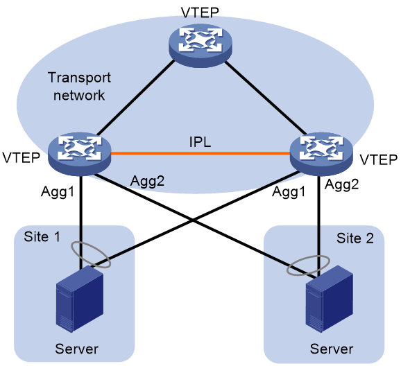
As shown in Figure 20, the working mechanism of VXLAN includes the support for DRNI.
· Synchronize the MAC address and ARP information.
The two VTEPs, acting as DR member devices, are connected through an intra-portal link (IPL) and synchronize their MAC address and ARP information over the IPL, ensuring consistency of MAC addresses and ARP information on both VTEPs. An IPL can be either an Ethernet aggregate link or a VXLAN tunnel.
|
|
NOTE: The VXLAN tunnel, serving as an IPL, automatically associates with all VXLANs on the device. |
· Use the same tunnel source IP address.
As DR member devices, the two VTEPs use the same tunnel source IP address to establish a VXLAN tunnel with other VTEPs.
· Backup dual-link AC at the customer site.
On the customer site, two VTEPs are connected to the same VM through an Ethernet link. A Layer 2 aggregate interface is established between the two links across devices, and this aggregate interface is configured as an AC (creating an Ethernet service instance on the aggregate interface, setting up packet matching rules and associating the Ethernet service instance with VSI). This AC is known as a dual-homed AC. In a VXLAN DRNI network, a dual-homed AC is used to prevent a single Ethernet link failure from disabling the VM's network access.
¡ When an Ethernet aggregate link is used as an IPL, the customer site link backup mechanism is as follows: After configuring the Layer 2 aggregate interface to be AC, the VTEP will automatically create an AC with the same packet match rule and associated with the same VSI on the IPL. When an AC fails on a VTEP, the packets received from the VXLAN tunnel and transmitted to this AC will be forwarded through the IPL to another VTEP. This VTEP determines the VSI to which the packet belongs based on the AC configured on the IPL, and forwards the packet, ensuring that the forwarding is not disrupted.
¡ When a VXLAN tunnel is used as an IPL, the customer site link backup mechanism is as follows: if an AC on one VTEP fails, that VTEP, after receiving packets sent to the failed AC through the VXLAN tunnel, adds VXLAN encapsulation to the packets. The encapsulated VXLAN ID is the corresponding VXLAN ID of the VSI that the failed AC belongs to. Subsequently, it forwards these packets through the VXLAN tunnel serving as a peer-link to another VTEP. This VTEP then identifies the VSI that the packets belong to based on the VXLAN ID, and forwards these packets.
· Single access point intercommunication
In the VXLAN DRNI network, the AC configurations on the two VTEPs that form the DR system might not be consistent. If one AC is only connected to one VTEP, this AC is called a single-homed AC. The communication between different single-homed ACs under the two VTEPs that form the DR system is realized through the IPL.
¡ When an Ethernet aggregate link is used as an IPL, the single-homed AC intercommunication mechanism is as follows: After the interface is configured as a single-homed AC, the VTEP will automatically create an AC with the same packet matching rules and associated with the same VSI on the IPL. When a packet is received from the single-homed AC, it will be forwarded to another VTEP through the IPL. The VTEP then determines the packet's VSI based on the AC configured on the IPL and forwards the packet.
¡ When a VXLAN tunnel is used as an IPL, the single-homed AC intercommunication mechanism is as follows: after receiving a packet from the single-homed AC, the packet is encapsulated with VXLAN, and the encapsulation's VXLAN ID is the corresponding VXLAN ID of the VSI to which the single-homed AC belongs. The packet is then forwarded to another VTEP through the VXLAN tunnel that serves as the IPL. This VTEP determines the packet's VSI based on the VXLAN ID and forwards the packet accordingly.
Typical network applications
VXLAN Layer 2 interconnect network
In a VXLAN Layer 2 interconnect network, VMs belonging to the same VXLAN are part of the same logical Layer 2 network and can communicate with each other at Layer 2. VMs in different VXLANs are isolated at Layer 2. Tenants accessing the VXLAN network can plan their own virtual networks without considering the restrictions of physical network IP addresses and multicast domain limitations, reducing the difficulty of network management.
The VXLAN Layer 2 interconnect network is shown in Figure 21. The VTEP is the edge device of the VXLAN network. A VXLAN tunnel is a point-to-point logic tunnel between two VTEPs, used for traffic forwarding between different VTEPs.
Figure 21 Schematic diagram of VXLAN Layer 2 interconnect network

Centralized VXLAN IP gateway network
In the centralized VXLAN IP gateway network topology, the gateway is deployed on the Spine device. The advantage of a centralized gateway is that all traffic will pass through the Spine device, which facilitates convenient traffic control and automatic diversion functions. The disadvantage is that the Spine device processes all Layer 3 traffic, creating considerable pressure, and is not suitable for deployment in large-scale networks.
The typical network of a centralized VXLAN IP gateway is shown in Figure 22. The VTEP is the edge device for the VXLAN network, and the Spine is the border gateway device connected to the wide area network (WAN). VMs use VXLAN to establish Layer 2 interconnect between different sites, and achieve Layer 3 interconnect with the WAN through the VXLAN IP gateway.
Figure 22 Schematic diagram of centralized VXLAN IP gateway network
Distributed VXLAN IP gateway network
In a distributed VXLAN IP gateway network, each VTEP can act as a VXLAN IP gateway, performing Layer 3 forwarding for local site traffic, effectively alleviating the pressure on the gateway.
The typical network configuration of a distributed VXLAN IP gateway is as shown in Figure 23. The Leaf is the device for the distributed VXLAN IP gateway, and the Border is the border gateway device connected to the WAN. The VM achieves Layer 3 interconnection between different VXLAN networks through the distributed VXLAN IP gateway, and establishes a Layer 3 interconnection with the WAN through the border gateway.
Figure 23 Schematic diagram for distributed VXLAN IP gateway network
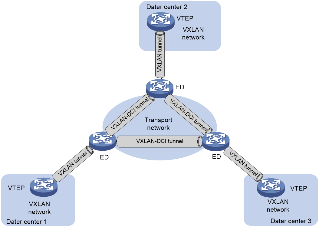
VXLAN DCI network
The VXLAN DCI technology establishes VXLAN Data Center Interconnect (VXLAN-DCI) tunnels between DCs, enabling communication between VMs in different DCs.
As shown in Figure 24, the edge devices of the DC are Edge Devices (EDs). VXLAN-DCI tunnels are established between EDs, using VXLAN encapsulation format. An ED establishes a VXLAN tunnel with a VTEP inside the DC. After receiving a packet from the VXLAN tunnel or VXLAN-DCI tunnel, the ED decapsulates the VXLAN, re-encapsulates the packet according to the destination IP address, and forwards it to the VXLAN-DCI tunnel or VXLAN tunnel, thereby achieving intercommunication between data centers.
Figure 24 Schematic diagram of typical VXLAN DCI network
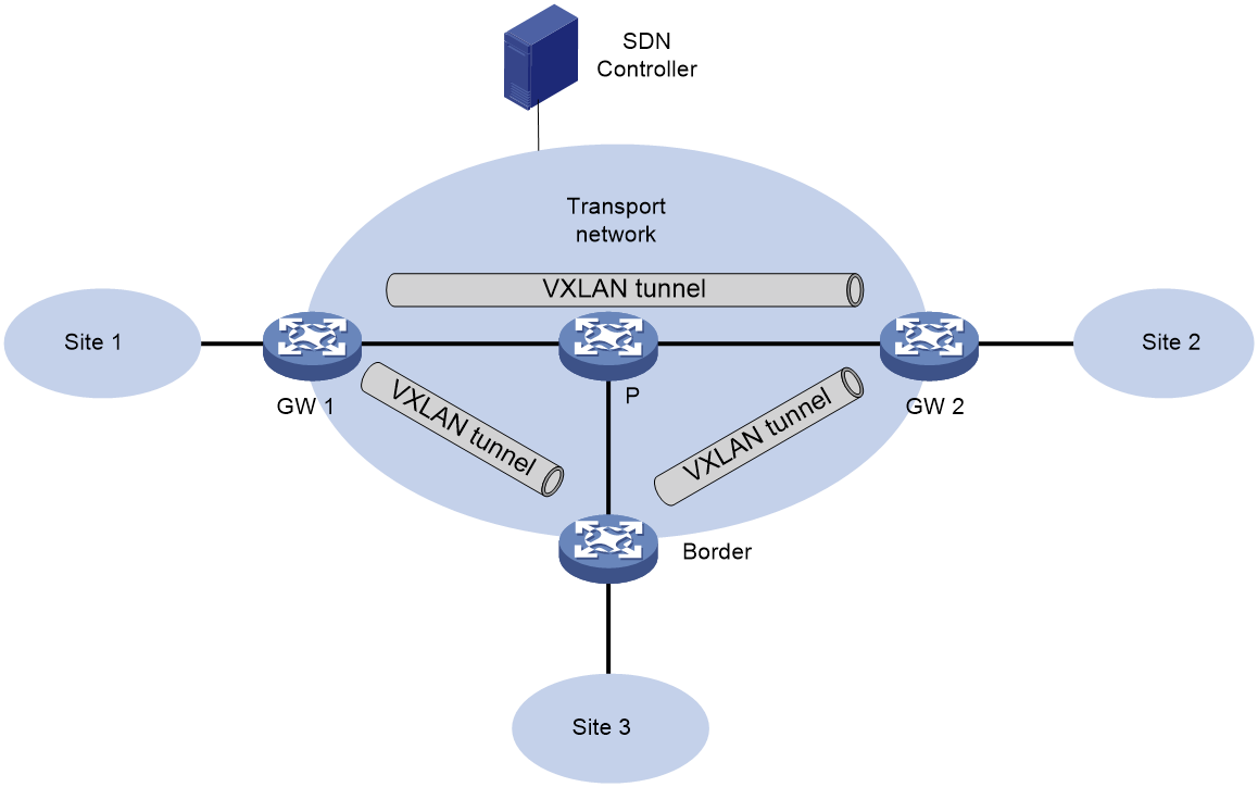
VXLAN collaboration with the SDN controller for network configuration
Software Defined Network (SDN) is a novel network schema that separates the control plane from the forwarding plane, with the SDN controllers centrally controlling and managing all network device. As shown in Figure 25, VXLAN can work in conjunction with SDN controllers, where all devices in the VXLAN network are centrally managed by the SDN controller through standard protocols, reducing the complexity of traditional device management. Meanwhile, when user services need expansion, centralized management allows users to conveniently and fast deploy network devices, facilitating the network's expansion and management.
Figure 25 Schematic diagram of network configuration in cooperation with VXLAN and SDN controller
References
RFC 7348: Virtual eXtensible Local Area Network (VXLAN): A Framework for Overlaying Virtualized Layer 2 Networks over Layer 3 Networks
