- Released At: 18-04-2024
- Page Views:
- Downloads:
- Table of Contents
- Related Documents
-
SRv6 VPN Technology White Paper
Copyright © 2024 New H3C Technologies Co., Ltd. All rights reserved.
No part of this manual may be reproduced or transmitted in any form or by any means without prior written consent of New H3C Technologies Co., Ltd.
Except for the trademarks of New H3C Technologies Co., Ltd., any trademarks that may be mentioned in this document are the attribute of their respective owners.
The content in this article is general technical information, some of which may not be applicable to the product you purchased.
Contents
BGP overlay service extensions
SRv6 VPN packet forwarding methods
Implementation process of IP L3VPN over SRv6 BE
Implementation process of IP L3VPN over SRv6 TE
Implementation process of EVPN L3VPN over SRv6 BE
Implementation process of EVPN L3VPN over SRv6 TE
Implementation process of EVPN VPWS over SRv6 BE
Implementation process of EVPN VPWS over SRv6 TE
EVPN VPWS over SRv6 multihoming
Implementation process of EVPN VPLS over SRv6 BE
Implementation process of EVPN VPLS over SRv6 TE
EVPN VPLS over SRv6 multihoming
Implementation process of IP public network over SRv6 BE
Implementation process of IP public network over SRv6 TE
Introduction to SRv6 inter-AS VPN
SRv6 inter-AS VPN packet forwarding methods
About the VPN-to-VPN connection method
Implementation process of VPN-to-VPN connection
About the MP-EBGP connection method
Implementation process of SRv6 BE forwarding in MP-EBGP connection mode
Implementation process of SRv6 TE forwarding in MP-EBGP connection mode
About L3VPN over SRv6 interworking.
Intra-AS L3VPN over SRv6 interworking
L3VPN over SRv6 Option A interworking
L3VPN over SRv6 Option B interworking
Interworking between MPLS L2VPN (or VPLS) and SRv6
Interworking between EVPN VPWS over SRv6 and EVPN VPWS
Interworking between EVPN VPLS over SRv6 and EVPN VPLS
SRv6 VPN reliability mechanisms
Networking scenarios for SBFD for SRv6 BE
Operating mechanism of SBFD for SRv6 BE
Overview
Technical background
In traditional VPN networks, virtual private communication networks are established in the public network by deploying label distribution protocols such as LDP/RSVP-TE. This method of deployment is complex and costly to maintain. These issues can be resolved by deploying SRv6 VPN in the public network. SRv6 VPN is a technology that carries VPN services in the IPv6 network through SRv6 tunnels, with the control plane advertising VPN routing information via MP-BGP and the data plane forwarding packets using SRv6 encapsulation. When the physical sites of a tenant are dispersed in different locations, SRv6 VPN can provide Layer 2 or Layer 3 interconnectivity for the different physical sites of the same tenant based on the existing service provider or enterprise IP networks.
Based on the types of VPN services, SRv6 VPN is divided into:
· L3VPN Services: IP L3VPN over SRv6 and EVPN L3VPN over SRv6.
· L2VPN Services: EVPN VPWS over SRv6 and EVPN VPLS over SRv6.
Benefits
The SRv6 VPN technology has the following advantages:
· Simple maintenance.
Only the source node needs to control and maintain path information. Other nodes in the network do not need to maintain path information.
· Intelligent control
SRv6, based on SDN design, bridges the gap between applications and networks, better facilitating the Application-Driven Network (AD-NET). In SRv6, the forwarding path, forwarding behavior, and service types are all controllable.
· Simple deployment.
SRv6 is implemented based on IGP and BGP extensions, eliminating the need for MPLS labels and deployment of label distribution protocols, making the configuration simple.
In the SRv6 network, you can deploy new services without a large-scale upgrade of network devices. In the data center and wide area network, only the network boundary devices and specific network node need to support SRv6, while other devices just need to support IPv6.
· Easy implementation of new services such as VPN.
SRv6 defines various types of SIDs, each having a unique function, indicating different forwarding actions. Through the operation of different SIDs, VPN and other services processing can be realized.
In the future, you can define new SID types according to your actual needs, demonstrating excellent expandability.
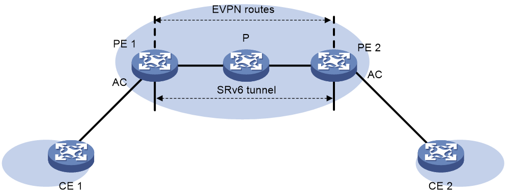
BGP overlay service extensions
BGP overlay service refers to the SRv6 VPN service based on BGP, using BGP as the control plane and SRv6 as the data plane to process L2VPN and L3VPN service packets. In the IP L3VPN/EVPN L3VPN/EVPN VPWS/EVPN VPLS over SRv6 network, Prefix SID path attribute can be carried when advertising NLRI through BGP protocol packets. The BGP Prefix SID path attributes are used to carry SRv6 SID and its relevant information. This attribute defines the following two types of TLV to implement L2VPN and L3VPN services.
· SRv6 service TLV.
· SRv6 Service Sub-TLV.
SRv6 Service TLV
The SRv6 service TLV is used to carry the service types of BGP overlay services.
The packet format of the SRv6 service TLV is shown as in Figure 1.
The SRv6 service TLV packet includes fields as shown in Table 1.
Table 1 Fields in SRv6 Service TLV
|
Field Name |
Length |
Description |
|
TLV Type |
8 bits |
Service types: · 5: L3 service · 6: L2 service |
|
TLV Length |
16-bit |
Length |
|
Reserved |
8 bits |
The reserved value is set to 0. |
|
SRv6 Service Sub-TLVs |
32-bit |
The information related to SRv6 service is composed of a series of TLV groups. |
SRv6 Service Sub-TLV
The SRv6 Service Sub-TLV is used to carry BGP Prefix SID information.
The packet format of the SRv6 Service Sub-TLV is as shown in Figure 2.
The SRv6 Service Sub-TLV packet includes fields as shown in Table 2.
Table 2 Fields in SRv6 Service Sub-TLV
|
Field Name |
Length |
Description |
|
SRv6 Service Sub-TLV Type |
8 bits |
Service type, with a value of 1. |
|
SRv6 Service Sub-TLV Length |
16 bits |
Length |
|
Reserved1 |
8 bits |
Reservation value, set to 0. |
|
SRv6 SID Value |
128-bit |
SRv6 SID value. |
|
SRv6 SID Flags |
8-bit |
Flag bit, currently undefined. |
|
Behavior of SRv6 Endpoint |
16-bit |
SRv6 SID Type: · End SID · End.X SID · End.T SID · End.DX6 SID · End.DX4 SID · End.DT6 SID · End.DT4 SID · End.DX2 SID · End.DX2V SID · End.DT2U SID · End.DT2M SID |
|
Reserved2 |
8 bits |
The reserved value is 0. |
|
SRv6 Service Data Sub-Sub-TLV |
32-bit |
Identify the attributes of SRv6 SID. |
SRv6 VPN packet forwarding methods
SRv6 BE
Segment Routing IPv6 Best Effort (SRv6 BE) refers to advertising the Locator through the IGP protocol. The nodes in the SRv6 network calculate the optimal route to reach the Locator following the shortest path first (SPF) algorithm. This route corresponds to the SRv6 BE path.
After the BGP route of the public network or the BGP route of the VPN-instance iterates to the SRv6 BE path, it is possible to steer the traffic of the public network or VPN into the SRv6 BE path.
SRv6 TE
Segment Routing IPv6 Traffic Engineering (SRv6 TE) is implemented based on SRv6 TE Policy. The entry node of the packets guides public network traffic or VPN traffic into the SRv6 TE Policy for forwarding, using various traffic engineering methodologies. The path corresponding to the SRv6 TE Policy is the SRv6 TE path.
IP L3VPN over SRv6
As shown in Figure 3, IP L3VPN over SRv6 uses MP-BGP to advertise user site IPv4/IPv6 private network routes on the IPv6 backbone network. It utilizes SRv6 paths between PEs to carry private network packets, thereby achieving connection to users belonging to the same VPN but located in different geographical locations through the IPv6 backbone network.

In IP L3VPN over SRv6, the following SRv6 SIDs are supported:
· End.DT4 SID: Used for identify a certain IPv4 VPN-instance within a network. The corresponding forwarding action of End.DT4 SID is to perform decapsulation of the packet and search the routing table of the IPv4 VPN-instance for forwarding. End.DT4 SID is used in the scenario of IPv4 private network users accessing the network.
· End.DT6 SID: Used for identify an IPv6 VPN-instance in the network. The corresponding forwarding action of the End.DT6 SID is decapsulation of the packet, followed by a search of the IPv6 VPN-instance routing table for forwarding. End.DT6 SID is used in the scenario of IPv6 private network user access.
· End.DT46 SID: Used for identify either an IPv4 or IPv6 VPN-instance in the network. The forwarding action corresponding to the End.DT46 SID is decapsulation of the packet and the search for the forwarding IPv4 or IPv6 VPN-instance routing table. End.DT46 SID is used in scenarios where IPv4 and IPv6 private network users access.
· End.DX4 SID: Used for identify the next IPv4 hop in the network. The corresponding forwarding action of End.DX4 SID is to decapsulate the packet and forward the decapsulated IPv4 packet to the specific next hop through the Layer 3 interface bound to that SID. End.DX4 SID is used in the scenario of IPv4 private network user access.
· End.DX6 SID: Used for identify a specific IPv6 next hop in the network. The forwarding action corresponding to End.DX6 SID is to decapsulate the packets and then forward the decapsulated IPv6 packets to the specific next hop via the third layer interface bound with this SID. End.DX6 SID is used for the scenario of IPv6 private network user access.
|
|
NOTE: · The advertisement and forwarding process types of various SRv6 SIDs will be explained. Below, only the End.DT4 SID is used as an example for illustration. · The implementation process of IPv4 L3VPN over SRv6 and IPv6 L3VPN over SRv6 is similar. We will illustrate using the example of IPv4 L3VPN over SRv6 in the following text. |
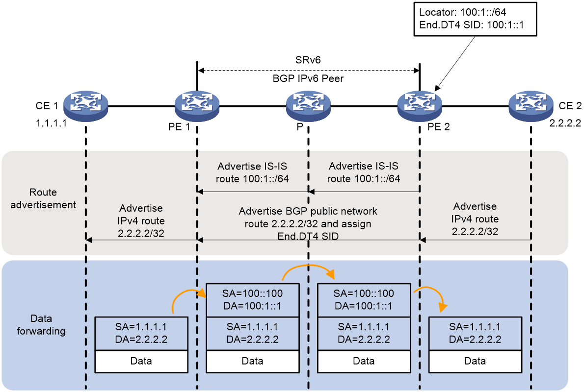
Implementation process of IP L3VPN over SRv6 BE
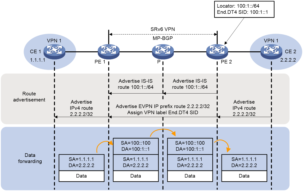
The process of route advertisement and packet forwarding for IP L3VPN over SRv6 BE is depicted in Figure 4.
Figure 4 Implementation Mechanism of IP L3VPN over SRv6 BE
The PE needs to advertise the route of the network segment, which the End.DT4 SID belongs to, to all devices in the public network through IGP protocol. For instance, PE 2 advertises the route of Locator of End.DT4 SID, namely 100:1::/64, to P and PE 1 via IGP protocol (taking IS-IS route as an example).
The process of advertising the private network route from CE 2 to CE 1 is as follows:
1. Using IGP or BGP, CE 2 advertises the private network route 2.2.2.2/32 of this site to PE 2.
2. After learning the private network routing information from CE 2, PE 2 stores the private network route in the routing table of VPN-instance A. PE 2 adds RD and RT attributes to the private network route, and assigns End.DT4 SID 100:1::1 to the private network route, forming a VPNv4 route. PE 2 then advertises the VPNv4 route to PE 1 via MP-BGP.
3. After receiving the VPNv4 route, PE 1 adds it to the routing table of VPN instance A, and advertises the VPNv4 route as an IPv4 route to CE 1. After receiving the IS-IS route advertised by PE 2, PE 1 adds it into the routing table.
4. After receiving the route, CE 1 learns it to the routing table.
After the completion of the route advertisement, the forwarding process of a packet with the destination address 2.2.2.2 from CE 1 to CE 2 is as follows:
1. CE 1 transmits an IPv4 packet with a destination address of 2.2.2.2 to PE 1.
2. After PE 1 receives a private network packet from the interface that is bound to VPN-instance A, it looks for a route that matches 2.2.2.2 in the routing table of VPN-instance A and finds the corresponding End.DT4 SID 100:1::1. Then, it encapsulates an IPv6 packet header for the packet. The source address in the IPv6 packet header is manually configured by the administrator, and the destination address is End.DT4 SID 100:1::1.
3. PE 1 finds the IPv6 routing table based on End.DT4 SID 100:1::1, and forwards the packet to P through the optimal IGP route.
4. Based on the End.DT4 SID 100:1::1, the IPv6 routing table is searched, and the packet is forwarded to PE 2 via the most optimal IGP route.
5. After receiving a packet with the destination IPv6 address as End.DT4 SID 100:1::1, PE 2 performs decapsulation to remove the IPv6 packet header. It matches the End.DT4 SID to VPN-instance A, looks up the routing table of VPN-instance A, and then transmits the packet to CE 2.
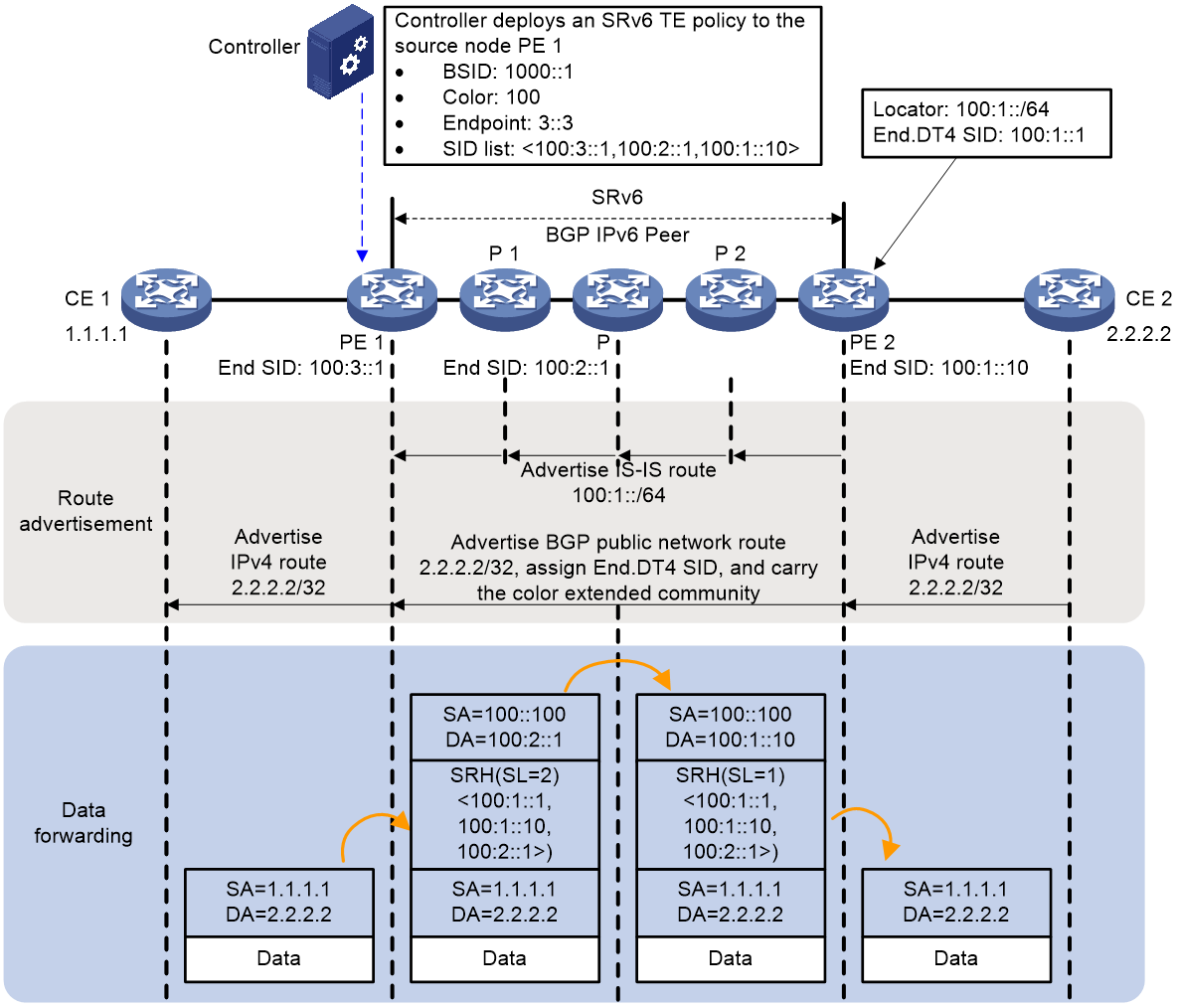
Implementation process of IP L3VPN over SRv6 TE
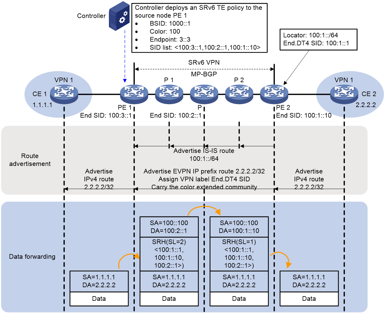
The process of IP L3VPN over SRv6 TE route advertisement and packet forwarding is shown in Figure 5. In this network segment, the controller sends the SRv6 TE Policy related configurations to PE 1. PE 1, P, and PE 2 then advertise the route of the Locator where the End SID is located in the public network via IGP protocol.
Figure 5 The implementation mechanism of IP L3VPN over SRv6 TE

PEs need to advertise the route of the network segment belonging to End.DT4 SID to all devices in the public network via the IGP protocol. Using PE 2 as an example, it advertises the End.DT4 SID Locator's network segment route 100:1::/64 to P 2, P, P 1, and PE 1 via the IGP protocol (IS-IS route as an example).
For example, the process of the private network route from CE 2 being advertised to CE 1 using the color-based traffic steering is as follows:
1. CE 2 uses IGP or BGP to advertise the private network route 2.2.2.2/32 of its own site to PE 2.
2. After learning the private network routing information from CE 2, PE 2 stores it in the routing table of the VPN-instance A. PE 2 adds RD and RT attributes to the private network route and allocates End.DT4 SID 100:1::1 to it, forming a VPNv4 route. PE 2 then advertises the VPNv4 route, carrying End.DT4 SID and Color extended community attribute, to PE 1 via MP-BGP.
3. After receiving the VPNv4 route, PE 1 adds it to the routing table of VPN-instance A, and the BGP route is iteratively diverted to SRv6 TE Policy using the color-based traffic steering. PE 1 converts the VPNv4 route into an IPv4 route and advertises it to CE 1. Upon receiving the IS-IS route advertised by PE 2, PE 1 learns it and adds it to the routing table.
4. Upon receiving the route, CE 1 learns it into the routing table.
Upon completion of the route advertisement, the forwarding process of the packet with a destination address of 2.2.2.2 from CE 1 to CE 2 is as follows:
1. CE 1 transmits an IPv4 packet with a destination address of 2.2.2.2 to PE 1.
2. After receiving a private network packet from an interface bound to VPN-instance A, PE 1 searches for a route that matches 2.2.2.2 in the routing table of VPN-instance A. It finds the corresponding End.DT4 SID 100:1::1, and the next hop for this route is SRv6 TE Policy. PE 1 adds an SRH to the packet, encapsulates the SID List of the SRv6 TE Policy and End.DT4 SID, and then encapsulates the basic IPv6 header information. Once completed, the packet is forwarded to P 1.
3. The packet is forwarded to P by looking up the IPv6 routing table according to the destination address and passing through the optimal IGP route.
4. After receiving the packet, the following operations are executed:
¡ Check the SL value in the SRH header. If SL > 0, reduce the SL value by 1. Update the destination address to the address indicated by SL. That is, if SL = 1, the IPv6 address 100:1::10 corresponds to Segment List [1].
¡ Look up the routing table based on the destination address in the IPv6 header and forward the packet to P 2.
5. According to the destination address, look up the IPv6 routing table and forward the packet to PE 2 via the optimal IGP route.
6. After PE 2 receives the packet, it uses the IPv6 destination address of the packet to search the Local SID table, matches the End SID, reduces the SL of the packet by 1, and updates the IPv6 destination address to End.DT4 SID 100:1::1. It uses the IPv6 destination address 100:1::1 to search the Local SID table, matches the End.DT4 SID, executes the forwarding action corresponding to the End.DT4 SID, that is, decapsulates the IPv6 packet header. Then, it matches the VPN-instance A based on the End.DT4 SID, looks up the routing table of VPN-instance A, and transmits the packet to CE 2.
EVPN L3VPN over SRv6
As shown in Figure 6, EVPN L3VPN over SRv6 uses EVPN's IP prefix routes adverstised via MP-BGP on the IPv6 backbone network to advertise user site routes for IPv4/IPv6 private networks. It leverages SRv6 path between PEs to bear private network packets, thereby enabling connection through the IPv6 backbone network for users located in different geographical locations but belonging to the same VPN.
Figure 6 EVPN L3VPN over SRv6 network diagram
In EVPN L3VPN over SRv6, the following SRv6 SIDs are supported:
1. End.DT4 SID: Used for identify a specific IPv4 VPN-instance in the network. The corresponding forwarding action of End.DT4 SID is to decapsulate the packet and look up the IPv4 VPN-instance routing table for forwarding. End.DT4 SID is used in the scenario of IPv4 private network user access.
2. End.DT6 SID: Used for identify a certain IPv6 VPN-instance in the network. The corresponding forwarding action of the End.DT6 SID is to decapsulate the packet and look up the VPN-instance routing table for forwarding. End.DT6 SID is used in the scenario of private network user access to IPv6.
· End.DT46 SID: Used for identify a specific IPv4 VPN-instance or IPv6 VPN-instance in the network. The corresponding action for End.DT46 SID is decapsulation of the packet and forward lookup in the routing table of the IPv4 VPN-instance or IPv6 VPN-instance. The End.DT46 SID is used in scenarios where IPv4 private network users and IPv6 private network users are accessing.
· End.DX4 SID: Used for identify a certain IPv4 next hop in the network. The forwarding action corresponding to the End.DX4 SID is to decapsulate the packets and forward the decapsulated IPv4 packets to a specific next hop through the Layer 3 interface bound with this SID. End.DX4 SID is utilized in the scenario of IPv4 private network user access.
· End.DX6 SID: Used for identify the next IPv6 hop in a network. The forwarding action corresponding to End.DX6 SID is to decapsulate the packet and forward the decapsulated IPv6 packet to the specific next hop through the Layer 3 interface bound with this SID. End.DX6 SID is used in the scenario of IPv6 private network user access.
|
|
NOTE: · The advertisement and forwarding processes for various SRv6 SID types are discussed below, illustrated specifically with the example of End.DT4 SID. · The implementation process of IPv4 EVPN L3VPN over SRv6 is similar to that of IPv6 EVPN L3VPN over SRv6. The following uses IPv4 EVPN L3VPN over SRv6 as an example for explanation. |
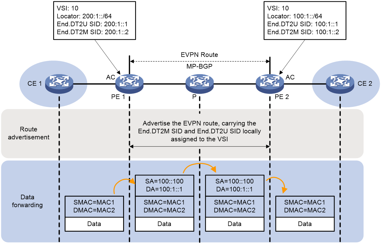
Implementation process of EVPN L3VPN over SRv6 BE
The advertisement and packet forwarding process of EVPN L3VPN over SRv6 BE route is depicted in Figure 7.
Figure 7 Mechanism of implementing EVPN L3VPN over SRv6 BE
The PE routers need to advertise the route for the network segment associated with the End.DT4 SID locator to all devices in the public network using the IGP protocol. For example, PE 2 passes the route 100:1::/64 of the network segment that the End.DT4 SID locator belongs to P and PE 1 through the IGP protocol (IS-IS route, for instance).
The process of advertising the private network route from CE 2 to CE 1 is as follows:
1. CE 2 uses IGP or BGP to advertise the private network route 2.2.2.2/32 of this site to PE 2.
2. After learning the private network routing information from CE 2, PE 2 stores the private network route in the routing table of VPN-instance A. PE 2 adds RD and RT attributes to the private network route, and allocates End.DT4 SID 100:1::1 to it, forming an EVPN IP prefix route. PE 2 then advertises the EVPN IP prefix route to PE 1 through MP-BGP.
3. After receiving the IP prefix route from EVPN, PE 1 adds this route to the routing table of VPN-instance A and advertises the IP prefix route from EVPN as an IPv4 route to CE 1. Following receipt of the IS-IS route advertised by PE 2, PE 1 learns it into the routing table.
4. Upon receiving the route, CE 1 learns it into the routing table.
After the route advertisement is completed, the process of forwarding packets with a destination address of 2.2.2.2 from CE 1 to CE 2 is as follows:
1. CE 1 transmits an IPv4 packet with a destination address of 2.2.2.2 to PE 1.
2. After PE 1, which is bound with VPN-instance A, receives a private network packet from the interface, it searches in the routing table of VPN-instance A for the route matching 2.2.2.2 and finds the corresponding End.DT4 SID 100:1::1. Then, it encapsulates the packet with an IPv6 packet header. The source address in the IPv6 packet header is manually configured by the administrator, and the destination address is End.DT4 SID 100:1::1.
3. PE 1 looks up the IPv6 routing table according to End.DT4 SID 100:1::1, and forwards the packet to P via the optimal IGP route.
4. Based on the End.DT4 SID 100:1::1, locate the IPv6 routing table and pass the packet to PE 2 through the optimal IGP route.
5. After PE 2 receives a packet with the
destination IPv6 address as End.DT4 SID 100:1::1, it performs decapsulation to
remove the IPv6 packet header. It then matches the End.DT4 SID to VPN-instance
A, searches for the routing table of VPN-instance A, and transmits the packet
to CE 2.
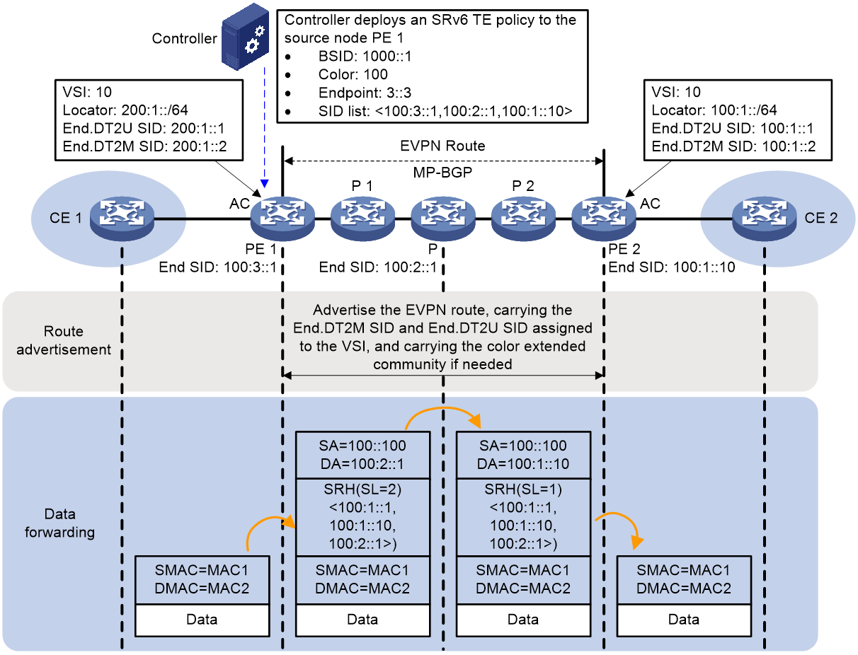
Implementation process of EVPN L3VPN over SRv6 TE
The process of EVPN L3VPN over SRv6 TE route advertisement and packet forwarding is as shown in Figure 8. In this network segment, the controller delivers the SRv6 TE Policy related configuration to PE 1. At the same time, PE 1, P and PE 2 advertise the route of the network segment where the End SID Locator resides on the public network, via the IGP protocol.
Figure 8 The implementation mechanism of EVPN L3VPN over SRv6 TE
The PEs need to advertise the route of the network segment of the End.DT4 SID Locator to all devices in the public network using the IGP protocol. For instance, PE 2 passes the route of the End.DT4 SID Locator network segment 100:1::/64 to P 2, P, P 1, and PE 1 through the IGP protocol using IS-IS route as an example.
Taking Color-based traffic steering as an example, the process of advertising the private network route from CE 2 to CE 1 is as follows:
1. CE 2 uses IGP or BGP to advertise the private network route 2.2.2.2/32 of this site to PE 2.
2. After PE 2 learns the private network routing information from CE 2, it stores the private network routing in the routing table of VPN-instance A. PE 2 adds RD and RT attributes to the private network route and assigns End.DT4 SID 100:1::1 to it, forming an EVPN IP prefix route. PE 2 then advertises the EVPN IP prefix route, carrying End.DT4 SID and Color extended community attribute, to PE 1 via MP-BGP.
3. Upon receiving the IP prefix route of EVPN, PE 1 adds it to the routing table of VPN-instance A, and the BGP route is iteratively redirected to SRv6 TE Policy via Color. PE 1 converts the IP prefix route of EVPN into an IPv4 route and advertises it to CE 1. After PE 1 receives the IS-IS route advertised by PE 2, it learns it into the routing table.
4. Upon receiving the route, CE 1 learns it and adds it to the routing table.
After the route advertisement, the forwarding process of the packet with a destination address of 2.2.2.2 from CE 1 to CE 2 is as follows:
1. CE 1 transmits an IPv4 packet with a destination address of 2.2.2.2 to PE 1.
2. After PE 1 receives a private network packet from an interface bound with VPN-instance A, it searches in the routing table of VPN-instance A for a route that matches 2.2.2.2. Once it finds the corresponding End.DT4 SID 100:1::1, and the next hop for this route is the SRv6 TE Policy, PE 1 adds a SRH to the packet, encapsulates the SID List of the SRv6 TE Policy and the End.DT4 SID, and then encapsulates the basic IPv6 header information. Upon completion, PE 1 forwards the packet to P 1.
3. According to the IPV6 routing table, Packet P is forwarded to its destination address using the optimal IGP route.
4. Upon receiving the packet, perform the following actions:
¡ Inspect the SL value in the SRH header. If SL > 0, reduce the SL value by 1, and update the destination address to the one indicated by SL, which means when SL equals 1, the corresponding Segment List [1]'s IPv6 address is 100:1::10.
¡ Search the routing table based on the destination address in the IPv6 header and forward the packet to P 2.
5. Based on the destination address, search the IPv6 routing table and forward the packet to PE 2 using the optimal IGP route.
6. Upon receipt of the packet, PE 2 uses the IPv6 destination address of the packet to look up the Local SID table, matching it to the End SID. It then reduces the SL of the packet by 1 and updates the IPv6 destination address to End.DT4 SID 100:1::1. Using the updated IPv6 destination address of 100:1::1, it again looks up the Local SID table and matches it to the End.DT4 SID. It then executes the forwarding action corresponding to the End.DT4 SID, performs decapsulation to remove the IPv6 packet header, and matches the End.DT4 SID to VPN-instance A. PE 2 then looks up the routing table of VPN-instance A and transmits the packet to CE 2.
EVPN VPWS over SRv6
EVPN VPWS over SRv6 refers to carrying EVPN VPWS services through SRv6 tunnels, transmitting layer 2 user data transparently through an IPv6 network, to establish a dot-to-dot connection which allows the customer network to pass through the IPv6 network.
Figure 9 Network diagram for EVPN VPWS over SRv6

As shown in Figure 9, PE nodes establish an SRv6 tunnel by advertising SRv6 SID through EVPN routing. This SRv6 tunnel serves as a PW, encapsulating and forwarding Layer 2 packets between site networks.
The transparent transmission of Layer 2 packet over EVPN VPWS over SRv6 is achieved by passing through the following SRv6 SID:
· End.DX2 SID: This represents the SID of a Layer 2 cross-connection, used to identify an endpoint. The forwarding action corresponding to End.DX2 SID is packet decapsulation, forwarding the decapsulated packet to the AC corresponding to the SID.
· The End.DX2L SID is used to identify packets from the Bypass SRv6 PW. Messages carrying this SID will not be forwarded to the Bypass SRv6 PW, thus preventing the creation of a loop. The corresponding forwarding action of the End.DX2L SID is decapsulation, which sends the decapsulated packets to the AC corresponding to the SID. Primarily, the End.DX2L SID is used for EVPN VPWS over SRv6 multi-homed site networking.
|
|
NOTE: The advertisement and forwarding process types of various SRv6 SID classes will be discussed. The following illustration will use the End.DX2 SID as an example. |
Implementation process of EVPN VPWS over SRv6 BE
The advertisement and packet forwarding process of EVPN VPWS over SRv6 BE route is shown in Figure 10.
Figure 10 The implementation mechanism of EVPN VPWS over SRv6 BE
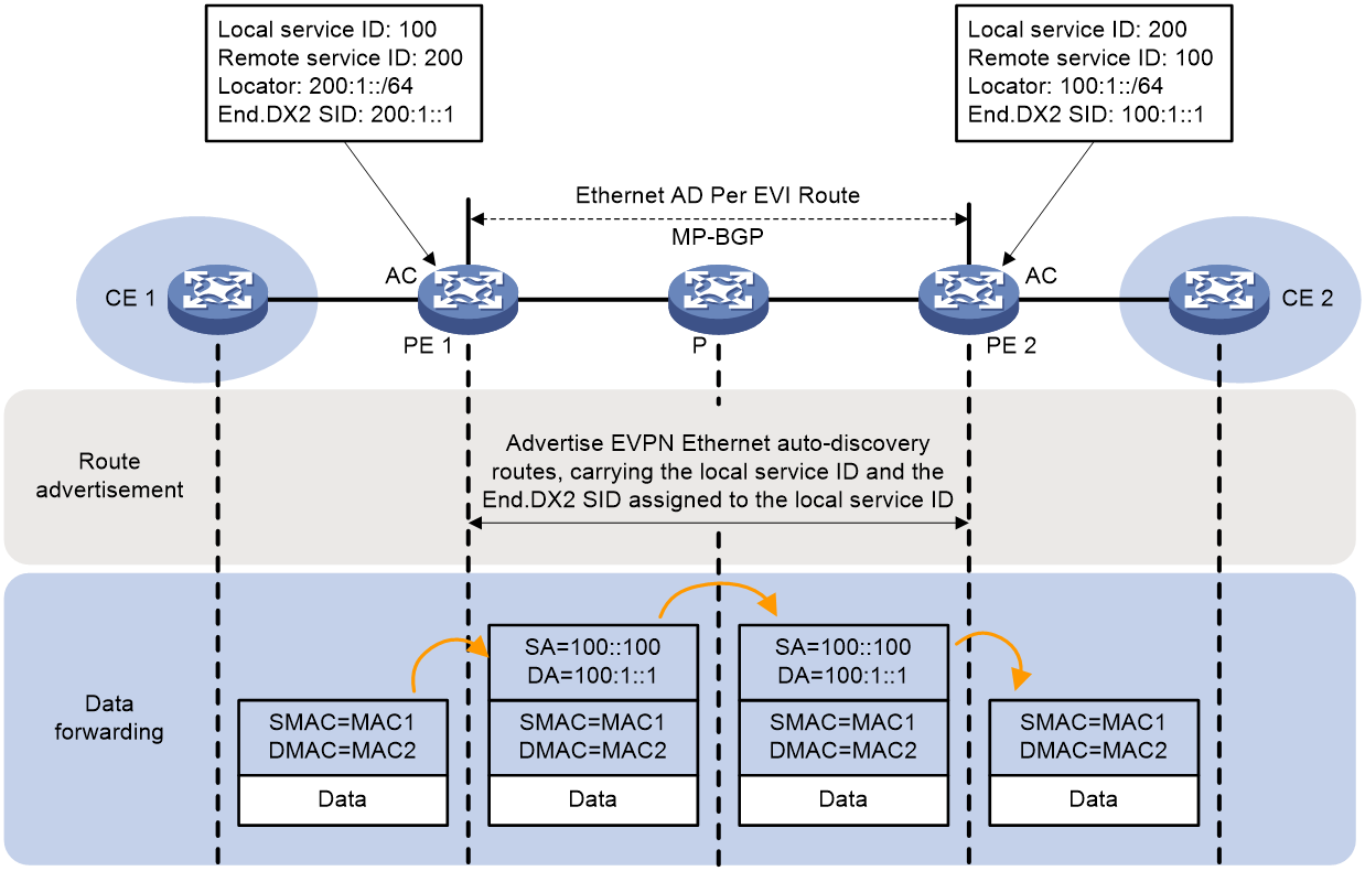
The process of establishing PW between PE via BGP EVPN route is as follows:
1. On both PE 1 and PE 2, configure the Local service ID to identify the connected CE. Configure the Remote service ID to identify the CE connected to the remote PE. Allocate an End.DX2 SID for each Local service ID, which serves as the entering SID for the PW.
2. The local PE (such as PE 1) advertises the Local service ID and the End.DX2 SID allocated for the Local service ID to the remote PE (such as PE 2) via the Ethernet Auto-discovery Per EVI route.
3. After receiving a route, PE 2 compares the Export target attribute in the route with the Import target attribute configured locally. If they match, PE 2 further compares the received Local service ID with the locally configured Remote service ID. If they are identical, a single-hop SRv6 tunnel from PE 2 to PE 1 is set up, with the End.DX2 SID advertised by PE 1 serving as the outgoing SID for this SRv6 tunnel.
4. Meanwhile, PE 2 will also transmit an Ethernet Auto-discovery Per EVI route to PE 1. PE 1 compares the received Local service ID with the locally configured Remote service ID. If the two are the same, a single-hop SRv6 tunnel is established from PE 1 to PE 2.
5. Both ends of PE advertise End.DX2 SID and after establishing a single-hop SRv6 tunnel in both directions, two SRv6 tunnels form a PW, which is used to carry user's layer 2 data. This PW is referred to as SRv6 PW.
After the route advertisement is completed, the forwarding process of the Layer 2 packet from CE 1 to CE 2 is as follows:
1. CE 1 transmits a layer 2 packet to PE 1.
2. Upon receiving a layer 2 packet from the connection with CE 1 on AC, PE 1 searches for the SRv6 PW (i.e., SRv6 tunnel) associated with the AC. It locates the corresponding End.DX2 SID, which is the End.DX2 SID assigned to PE 1 by PE 2.
3. The administrator manually configures the source IPv6 address, and PE 1 encapsulates the outer layer of the packet with an IPv6 header, with the destination IPv6 address set to End.DX2 SID.
4. PE 1 looks up the IPv6 routing table based on the End.DX2 SID, and forwards the packet to P via the optimal IGP route.
5. According to the End.DX2 SID, find the IPv6 routing table, and pass the packet to PE 2 through the optimal IGP route.
6. PE 2 searches the Local SID table according to the End.DX2 SID, executes the forwarding action corresponding to the End.DX2 SID, that is, decapsulating the packet and matching the End.DX2 SID with its associated AC. The packet is then forwarded to CE 2 through the AC.
Implementation process of EVPN VPWS over SRv6 TE
The process of EVPN VPWS over SRv6 TE route advertisement and packet forwarding is shown in Figure 11. In this network segment, the controller sends the SRv6 TE Policy-related settings to PE 1. At the same time, PE 1, P, and PE 2 advertise the route of the network segment where the End SID is located on the public network via the IGP protocol.
Figure 11 EVPN VPWS over SRv6 TE implementation mechanism
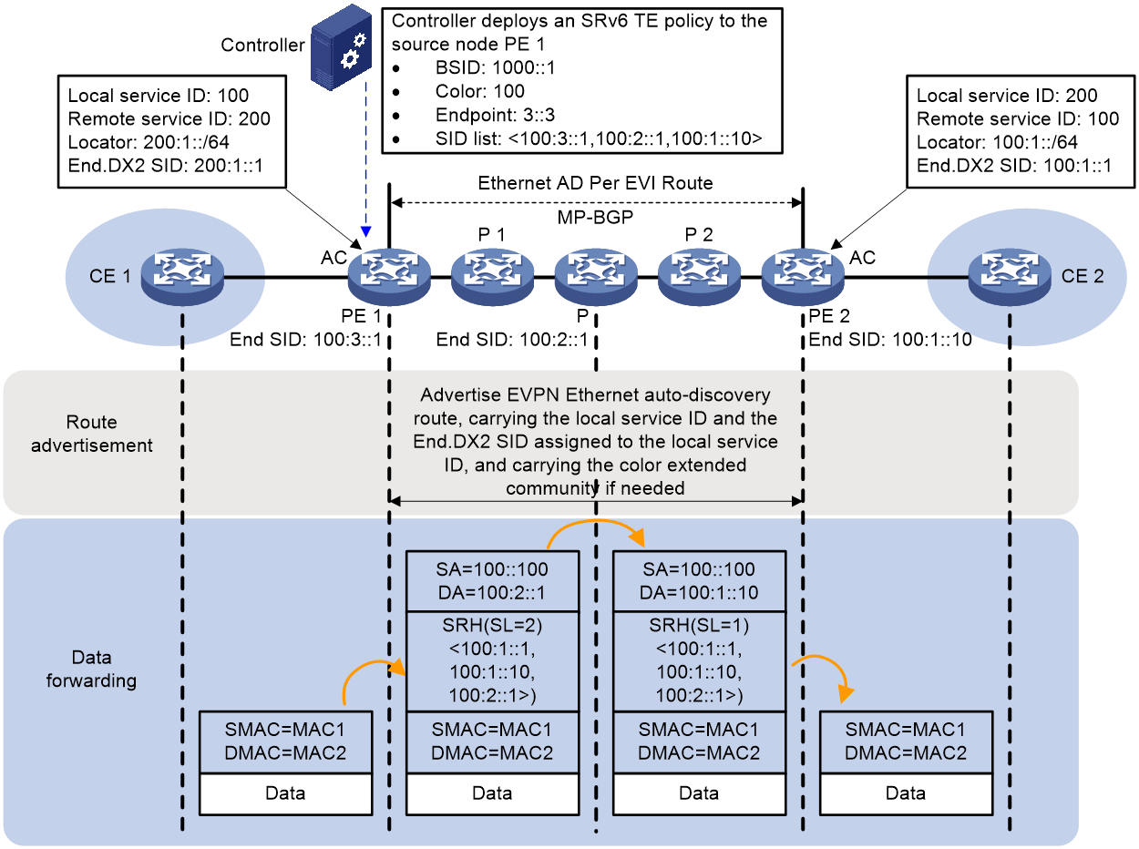
As an example of the color-based traffic steering, the process of establishing PW via BGP EVPN routing between PEs is as follows:
1. Local service IDs are configured on both PE 1 and PE 2 to identify the connected CEs. Remote service IDs are used to identify the CEs connected to the remote PE. Each Local service ID is allocated an End.DX2 SID, which serves as the PW's entry SID.
2. The local PE (like PE 1) advertises the Ethernet Auto-discovery Per EVI route to the remote PE (such as PE 2), which carries the local service ID and the End.DX2 SID assigned to the Local service ID. In this route, it can also carry the Color extended community attribute.
3. When PE 2 receives a route, if the Export target attribute in the route matches the locally configured Import target attribute of PE 2, then PE 2 compares the received Local service ID to the locally configured Remote service ID. If they are the same, a single-hop SRv6 tunnel from PE 2 to PE 1 is established, with the End.DX2 SID advertised by PE 1 serving as the exit SID for the SRv6 tunnel. PE 2, based on the Color attribute, iterates the route to the SRv6 TE Policy.
4. Meanwhile, PE 2 will also transmit the Ethernet Auto-discovery Per EVI route to PE 1. After receiving the route, PE 1 will process in the same way as PE 2.
5. Both ends of PE advertise End.DX2 SID, and after establishing single-hop SRv6 tunnels in both orientations, two SRv6 tunnels form a PW, which is used to carry user's layer-2 data. This PW is called SRv6 PW.
After the route advertisement is completed, the forwarding process of the Layer 2 packet from CE 1 to CE 2 is as follows:
1. CE 1 transmits Layer 2 packets to PE 1.
2. Upon receiving a Layer 2 packet from the connection AC linked to CE 1, PE 1 searches for the associated SRv6 PW (namely, SRv6 tunnel). It locates the matching End.DX2 SID, which is the SID allocated to PE 1 by PE 2, and identifies the SRv6 TE Policy that this SID iterates to. PE 1 enhances the packet with an SRH, encapsulates the SID List of the SRv6 TE Policy and the End.DX2 SID, and subsequently encapsulates the basic IPv6 header information. Once finished, PE 1 forwards the packet to P 1.
3. Based on the destination address, search for the IPv6 routing table, and forward the packet to P using the optimal IGP route.
4. After receiving the packet, perform the following operations:
¡ Check the SL value in the SRH header. If SL>0, decrease the SL value by 1. Update the destination address to the address indicated by SL, that is, the IPv6 address 100:1::10 corresponding to Segment List [1] when SL=1.
¡ Look up the routing table based on the destination address in the IPv6 header, and forward the packet to P2.
5. Based on the destination address, search the IPv6 routing table and pass the packet to PE 2 via the optimal IGP route.
6. After PE 2 receives the packet, it uses the IPv6 destination address of the packet to look up the Local SID table, matches End SID, reduces the SL of the packet by 1, and updates the IPv6 destination address to End.DX2 SID 100:1::1. Using the IPv6 destination address 100:1::1, it looks up the Local SID table, matches End.DX2 SID, and executes the forwarding action corresponding to End.DX2 SID, which is to decapsulate the packet. According to the match with End.DX2 SID, it associates with AC and passes the packet to CE 2 through this AC.
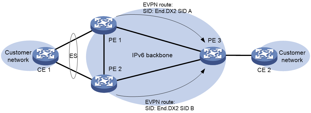
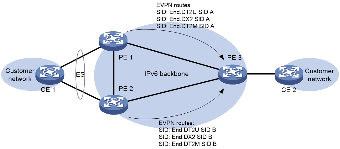
EVPN VPWS over SRv6 multihoming
As shown in Figure 12, when a site is connected to multiple PEs through different Ethernet links, these links form an Ethernet Segment (ES), identified by a common ES Identifier (ESI) to signify they belong to the same ES. Multiple connected PEs form a redundancy backup group, which can prevent single point failure of PE from affecting the network, thereby enhancing the network's reliability. EVPN VPWS over SRv6 supports only dualhoming.
Figure 12 EVPN VPWS over SRv6 multihoming
Redundancy mode
The redundancy backup modes supported by the multihoming networking include:
· Multi-active redundancy mode: All member PE in the redundancy backup group can forward traffic, creating load sharing among the member PEs.
· Single-active redundancy mode: In the redundancy backup group, only one PE in the member PEs forwards traffic. The two SRv6 PWs on the member PE have a primary-backup relationship. This ensures that when the primary SRv6 PW experiences a fault, the traffic is immediately switched over to the backup SRv6 PW, allowing the traffic forwarding to continue.
Route advertisement
Both member PEs in the redundancy backup group advertise End.DX2 SID to PE 3, and advertise to PE 3 the redundancy backup mode of multihoming sites and their status in the redundancy backup group (i.e., whether they are primary PE or backup PE). Depending on different redundancy backup modes, PE 3's processing varies.
· In the multi-active redundancy mode: PE 3 takes the routes advertised by PE 1 and PE 2 as equal cost routes and carries out load sharing between them.
· In single-active redundancy mode: PE 3 uses the route advertised by the main PE as the optimal route and forwards packets solely through this route.
EVPN VPWS over SRv6 FRR
The Fast Reroute (FRR) function of EVPN VPWS over SRv6 is used to minimize the impact on the network caused by an AC link fault or an SRv6 PW link fault, improving the network's reliability and stability. The FRR function of EVPN VPWS over SRv6 includes Bypass PW and primary/backup PW functions.
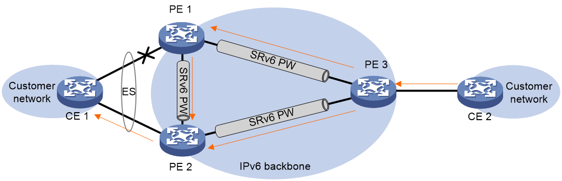
Bypass PW
As shown in Figure 13, in a network with multihoming site, when a link fault occurs on AC from the PE2 side, PE2 would announce inaccessible local information to both PE1 and PE3. As a result, the traffic no longer passes between PE1 and PE2 through SRv6 PW. During this period, frames sent by PE1 to PE2 cannot be forwarded to CE2 and will be discarded. The problem is solved by the 'Bypass PW' function of EVPN VPWS over SRv6. Redundancy backup group members build Bypass SRv6 PW between PEs. When a link fault occurs, PE2 will temporarily transmit traffic to PE3 via Bypass SRv6 PW, and then PE3 will forward to CE2, thus reducing packet loss.
Figure 13 Diagram of the Bypass PW function
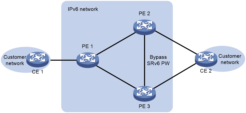
If a Bypass SRv6 PW is established between PE 2 and PE 3 using End.DX2 SID, a temporary loop is created when both the AC links on PE 2 and PE 3 fail, as they would retransmit the packets received from the other end via the Bypass SRv6 PW. This issue can be resolved by establishing a Bypass SRv6 PW between PE 2 and PE 3 using End.DX2L SID. The End.DX2L SID serves to identify packets coming from the Bypass SRv6 PW, and packets bearing this SID will not be forwarded to the Bypass SRv6 PW again, thereby avoiding the creation of a loop.
After enabling the Bypass PW function, the PE will prioritize using the End.DX2L SID to establish a Bypass SRv6 PW. If the End.DX2L SID does not exist, then the End.DX2 SID will be used to establish the Bypass SRv6 PW.
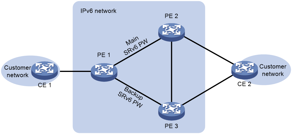
Primary and backup PWs
If there is only one SRv6 PW between two CEs, communication between the CEs will be disrupted when a fault occurs in the PE node, the link between the PE and CE, or the SRv6 PW between the PEs. The standby PW function is realized by deploying two standby SRv6 PWs. When the primary SRv6 PW encounters a fault, the traffic is immediately switched to the backup SRv6 PW, enabling continued traffic forwarding.
As shown in Figure 14, two SRv6 PWs are established between two CEs. Normally, the CE uses the main SRv6 PW for communication with the remote CE. When PE 1 detects that the SRv6 PW to PE 2 is unavailable (possibly due to a node fault in PE 2, an SRv6 PW fault, or a link fault between PE 2 and CE 2), PE 1 will enable the backup SRv6 PW. The packets from CE 1 are then transmitted to PE 3 via the backup SRv6 PW, and subsequently forwarded to CE 2 by PE 3. Upon receiving the packets, CE 2 switches the transmission of packets to CE 1 to the backup SRv6 PW by updating the MAC address entry, among other methods, thereby preventing communication disruption.
Figure 14 Primary and backup PWs
EVPN VPLS over SRv6
EVPN VPLS over SRv6 refers to carrying EVPN VPLS services through an SRv6 tunnel, transmitting user layer-2 data transparently over the IPv6 network, and establishing a point-to-multipoint connection for the customer network through the IPv6 network.
As shown in Figure 15, the PE establishes SRv6 tunnels by advertising SRv6 SID via EVPN routing. This SRv6 tunnel, acting as PW, encapsulates and forwards the layer 2 packets between site networks.
Figure 15 Network diagram of EVPN VPLS over SRv6
The transparent transmission of Layer 2 packets in EVPN VPLS over SRv6 is achieved by passing through the following SRv6 SID:
· End.DT2M SID: Used to transmit EVPN VPLS BUM (Broadcast, Unknown-unicast, Multicast) traffic. The corresponding forwarding action for the End.DT2M SID is to decapsulate the packet and flood the decapsulated packet within the VSI instance. PE assigns an End.DT2M SID to each VSI instance.
· End.DT2U SID: Used to carry known unicast traffic of EVPN VPLS. The corresponding forwarding action of End.DT2U SID is to decapsulate packets, look up the MAC address entry of the VSI instance based on the destination MAC address of the decapsulated packet, and forward the packet to the corresponding egress interface based on the MAC entry. PE allocates an End.DT2U SID for each VSI instance.
· End.DX2 SID: Used to convey the known unicast traffic of EVPN VPLS. The forwarding action corresponding to End.DX2 SID is the decapsulation of packets, which are then forwarded to the AC corresponding to the SID. An End.DX2 SID is allocated to each AC in the VSI instance by the PE.
· End.DT2UL SID: Used to identify packets originating from Bypass SRv6 PW. Packets carrying this SID will not be forwarded to the same Bypass SRv6 PW, thus preventing the creation of loops. The forwarding action corresponding to the End.DT2UL SID is to decapsulate the packet, find the MAC address entry of the VSI instance based on the packet's target MAC address after decapsulation, and forward the packet to the corresponding egress interface according to the MAC entry. The End.DT2UL SID is primarily used for EVPN VPLS over SRv6 multi-homed site networking. Each VSI instance will be allocated only one End.DT2UL SID.
· End.DX2L SID: Used to identify packets originating from Bypass SRv6 PW, and any packets bearing this SID will not be forwarded to the same Bypass SRv6 PW to prevent loop formation. The corresponding forwarding action for the End.DX2L SID is to decapsulate the packet and then forward the decapsulated packet to the AC corresponding to the SID. The End.DX2L SID is primarily used in EVPN VPLS over SRv6 multi-homed site networking. A unique End.DX2L SID is allocated to each multi-homed AC in the VSI instance by the PE.
|
|
NOTE: The advertisement and forwarding process types of various SRv6 SID classes will be discussed below, using only End.DT2M SID and End.DT2U SID as examples. |
Implementation process of EVPN VPLS over SRv6 BE
The process of BE route advertisement and packet forwarding in EVPN VPLS over SRv6 is illustrated in Figure 16.
Figure 16 EVPN VPLS over SRv6 BE
When the local PE advertises the EVPN route to the remote PE, it includes the End.DT2M SID and End.DT2U SID allocated to the VSI by the local PE in the EVPN route, thereby setting up an SRv6 tunnel from the local PE to the remote PE.
· The End.DT2M SID is advertised via IMET route to establish an SRv6 tunnel for BUM traffic.
· The End.DT2U SID establishes the SRv6 tunnel for known unicast traffic by advertising the route through MAC/IP.
Both ends of PE advertise End.DT2M SID and End.DT2U SID, and after establishing a single-hop SRv6 tunnel in both directions, two SRv6 tunnels form a PW to carry user layer 2 data.
Upon completion of the route advertisement, the forwarding process of the known unicast packet from CE 1 to CE 2 in the layer 2 is as follows:
1. CE 1 transmits a layer 2 packet to PE 1.
2. Upon receiving Layer 2 packets from the Access Controller connected to Customer Edge 1, Provider Edge 1 looks up the MAC address table in the associated Virtual Switching Instance, locates the corresponding Segment Routing over IPv6 tunnel, and obtains the End.DT2U Segment Identifier allocated by Provider Edge 2, which is the End.DT2U SID.
3. PE 1 encapsulates the outer layer of the packet with an IPv6 header, setting the destination IPv6 address as the End.DT2U SID. The source IPv6 address is manually configured by the administrator.
4. PE 1 searches the IPv6 routing table based on the End.DT2U SID, and forwards the packet to P via the optimal IGP route.
5. Based on the End.DT2U SID, the IPv6 routing table is searched. The packet is then forwarded to PE 2 via the optimal IGP route.
6. PE 2 locates the Local SID table based on the End.DT2U SID, executes the forwarding action corresponding to the End.DT2U SID, performs decapsulation on the packet, and looks up the MAC address table within the VSI to which the End.DT2U SID belongs. Based on the lookup result, the packet is forwarded to CE 2.
After completing the route advertisement, the forwarding process for Layer 2 broadcast, multicast, and unknown unicast packets is as follows:
1. CE 1 transmits Layer 2 broadcast, multicast, and unknown unicast packets to PE 1.
2. After receiving the layer 2 packet from the AC connected to CE 1, PE 1 looks for all the End.DT2M SIDs allocated by remote PEs in the VSI associated with the AC.
3. PE 1 encapsulates the outer layer of the packet with an IPv6 header. The destination IPv6 address is End.DT2M SID, and the source IPv6 address is manually configured by the administrator.
If PE 1 receives multiple End.DT2M SIDs allocated by remote PEs, it will encapsulate each individual End.DT2M SID for the layer 2 packets, and then forward these packets to all remote PEs.
4. PE 1 looks up the IPv6 routing table based on the End.DT2M SID, and passes the packet to P through the optimal IGP route.
5. The packet is passed to PE 2 through the optimal IGP route, after searching the IPv6 routing table based on the End.DT2M SID.
6. PE 2 locates the Local SID table using the End.DT2M SID, executes the forwarding action corresponding to the End.DT2M SID, which is the decapsulation of the packet, and broadcasts the packet within the VSI to which the End.DT2M SID belongs.
Implementation process of EVPN VPLS over SRv6 TE
The process of EVPN VPLS over SRv6 TE route advertisement and packet forwarding is shown in Figure 17. In this network segment, the controller sends the SRv6 TE Policy related configuration to PE 1, while PE 1, P and PE 2 advertise the route of the network segment where the End SID is located in the public network through the IGP protocol.
Figure 17 EVPN VPLS over SRv6 TE
When the local PE advertises the EVPN route to the remote PE, it carries the End.DT2M SID and End.DT2U SID allocated for the VSI at the local end, thereby establishing an SRv6 tunnel from the local PE to the remote PE.
· The End.DT2M SID is advertised through the IMET route, which is used to establish SRv6 tunnels for BUM traffic.
· The End.DT2U SID uses route advertisement via MAC/IP to establish SRv6 tunnels for known unicast traffic.
Both PE ends advertise the End.DT2M SID and the End.DT2U SID. After establishing a single-hop SRv6 tunnel in both directions, two SRv6 tunnels form a PW used to carry Layer 2 user data.
When PE uses SR-TE for packet forwarding, PE 2 will iterate the route to an SRv6 TE Policy based on the Color attributes and next-hop address received from the EVPN route. This is done by using techniques that either base on Color or employ a tunneling policy to divert the stream.
After the route advertisement is completed, the known unicast packet forwarding process from CE 1 to CE 2 is as follows in the layer 2:
1. CE 1 transmits a layer 2 packet to PE 1.
2. After receiving the layer-2 packet from the connection with CE 1 on AC, PE 1 searches the MAC address table in the associated VSI to find the corresponding SRv6 tunnel. It then obtains the End.DT2U SID of the tunnel, which is the End.DT2U SID allocated by PE 2, and finds the SRv6 TE Policy that the SID iterates to. PE 1 adds SRH to the packet, encapsulates the SID List of the SRv6 TE Policy and the End.DT2U SID, and then encapsulates the basic IPv6 header information. Finally, the packet is forwarded to P 1.
3. Based on the destination address, the IPv6 routing table is searched, and the packet is forwarded to P through the optimal IGP route.
4. After receiving the packet, execute the following operations:
¡ Check the SL value in the SRH header. If SL is greater than 0, decrease the SL value by 1. Update the destination address to the address indicated by SL. For instance, an SL value of 1 corresponds to the IPv6 address 100:1::10 in Segment List [1].
¡ Based on the destination address in the IPv6 header, look up the routing table and forward the packet to P 2.
5. According to the destination address, the packet is forwarded to PE2 via the optimal IGP route found in the IPv6 routing table.
6. Upon receiving the packet, PE 2 uses the IPv6 destination address from the packet to search the Local SID table. After matching with the End SID, it reduces the SL of the packet by 1 and updates the IPv6 destination address to End.DT2U SID 100:1::1. PE 2 then uses the new IPv6 destination address 100:1::1 to search the Local SID table again. After matching with the End.DT2U SID, it executes the forwarding action corresponding to the End.DT2U SID, which is to decapsulate the packet. Next, PE 2 searches the MAC address table within the VSI that the End.DT2U SID belongs to. Based on the result of this search, the packet is forwarded to CE 2.
After the route advertisement is completed, the forwarding process for Layer 2 broadcast, multicast, and unknown unicast packets is:
1. CE 1 transmits Layer 2 broadcast, multicast, and unknown unicast packets to PE 1.
2. Upon receiving a Layer 2 packet from the connection with CE 1 on AC, PE 1 searches in the associated VSI for all End.DT2M SIDs allocated by remote PEs, and finds out each SID's iterated SRv6 TE Policy. PE 1 then adds an SRH header to the packet, encapsulating the SID List of SRv6 TE Policy and End.DT2M SID, followed by encapsulating the basic IPv6 header information. Once done, the packet is forwarded to P 1. If PE 1 receives multiple End.DT2M SIDs allocated by remote PEs, it encapsulates each End.DT2M SID and its iterated SRv6 TE Policy's SID List for the Layer 2 packet, and forwards this packet to all remote PEs.
3. Check the IPv6 routing table based on the destination address, then forward the packet to P through the optimal IGP route.
4. Upon receiving the packet, execute the following operations:
¡ Check the SL value in the SRH header. If SL>0, decrease the SL value by 1. The destination address is then updated to the address indicated by the SL, i.e., the IPv6 address 100:1::10 of Segment List [1] corresponding to SL=1.
¡ Search the routing table according to the destination address in the IPv6 header, and forward the packet to P 2.
5. Following the destination address, the IPv6 routing table is searched. The packet is then forwarded to PE 2 via the optimal IGP route.
6. Upon receiving the packet, PE 2 uses the IPv6 destination address of the packet to look up the Local SID table. It matches the End SID, reduces the SL of the packet by 1, and updates the IPv6 destination address to End.DT2M SID 100:1::1. Using the updated IPv6 destination address 100:1::1, it looks up the Local SID table again, matching the End.DT2M SID. It then executes the forwarding action corresponding to End.DT2M SID, that is, it decapsulates the packet and broadcasts it within the VSI that belongs to the End.DT2M SID.
EVPN VPLS over SRv6 multihoming
As shown in Figure 18, when a site connects to multiple PEs via different Ethernet links, these links form an Ethernet Segment, with a common ES Identifier to indicate they belong to the same ES. The connected PEs form a redundancy backup group, which can avoid single point failures affecting the network and thus improve network reliability. EVPN VPLS over SRv6 supports only dualhoming.
Figure 18 EVPN VPLS over SRv6 multihoming
Redundancy mode
The redundancy backup modes supported by the multihoming networking include:
· Multi-active redundancy mode: All member PEs in the redundancy backup group can forward traffic, forming load sharing among the member PEs.
· Single-active redundancy mode: In the redundancy backup group, only one PE among the members forwards traffic. The two SRv6 PWs on the member PE have a primary and backup relationship. This ensures that if a fault occurs in the primary SRv6 PW, traffic is immediately switched over to the backup SRv6 PW, allowing traffic forwarding to continue.
Route advertisement
Both member PEs in the redundancy backup group advertise End.DT2U SID, End.DX2 SID, and End.DT2M SID to PE 3, and announce to PE 3 the redundancy backup mode of multiple affiliation sites and their states (main PE or backup PE) in the redundancy backup group. PE 3 handles differently under different redundancy backup modes.
· In multi-active redundancy mode: PE 3 treats the routes advertised by PE 1 and PE 2 as equal cost routes, performing load sharing between them.
· In single-active redundancy mode: PE 3 uses the route advertised by the main PE as the best route and forwards packets only through this route.
EVPN VPLS over SRv6 FRR
As shown in Figure 19, in the EVPN VPLS over SRv6 network with dual homing sites, CE 1 is dual homed to PE 1 and PE 2, where PE 1 is the DF. When there is a fault in the AC on the side of PE 1, PE 1 will delete the corresponding MAC address entry and announce to PE 2 and remote PE that the local site is unreachable, undoing the MAC address. At this point, packets already transmitted from remote PE to PE 1 will be discarded because there is no egress interface.
The issue is resolved by using the FRR function in EVPN VPLS over SRv6. With the FRR function enabled on PE 1, the corresponding MAC address entry is not deleted when there is a fault in the AC on the PE 1 side. Instead, the packets matching this MAC address entry are forwarded to PE 2 via the Bypass SRv6 PW between PE 1 and PE 2. Then PE 2 forwards them to CE 1, thus reducing packet loss caused by the AC fault.
Figure 19 EVPN VPLS over SRv6 FRR
If a Bypass SRv6 PW is established between PE 1 and PE 2 using End.DT2U SID or End.DX2 SID, then when the AC links on PE 1 and PE 2 both fault, PE 1 and PE 2 will resend the packets received from the counterpart through Bypass SRv6 PW, causing a temporary loop. This issue can be resolved by using End.DT2UL SID or End.DX2L SID to establish a Bypass SRv6 PW between PE 1 and PE 2. End.DT2UL SID and End.DX2L SID are used to identify packets from the Bypass SRv6 PW, and packets carrying this SID will not be forwarded to that Bypass SRv6 PW, thus avoiding the formation of a loop.
Once the FRR function is enabled, the PE will prefer to use the End.DT2UL SID or End.DX2L SID to establish Bypass SRv6 PW. If there is no End.DT2UL SID and End.DX2L SID, it will use End.DT2U SID or End.DX2 SID to establish Bypass SRv6 PW.
IP public network over SRv6
As shown in Figure 20, IP public network over SRv6 advertises IPv4/IPv6 routes of user sites on the IPv6 backbone network through MP-BGP. It uses the SRv6 path between PEs to carry user packets, thereby achieving the connection of users located in different geographical locations through the IPv6 backbone network.
Figure 20 IP public network over SRv6
The following SRv6 SID is supported in IP public network over SRv6:
· End.DT4 SID: Identifies the IPv4 public network. Its forwarding action decapsulates packets and looks up the IPv4 public routing table for forwarding. It's used for IPv4 user access scenarios.
· End.DT6 SID: Identifies the IPv6 public network. Its forwarding action decapsulates packets and searches the IPv6 public routing table for forwarding. It's used for IPv6 user access scenarios.
· End.DT46 SID: Identifies either the IPv4 or IPv6 public network. Its forwarding action decapsulates packets and consults either the IPv4 or IPv6 public routing table for forwarding. It's used for both IPv4 and IPv6 user access scenarios.
· End.DX4 SID: Identifies a specific IPv4 next-hop in the network. Its forwarding action decapsulates packets and forwards the resulting IPv4 packets to the specific next-hop via the bound Layer 3 interface. It's used for IPv4 user access scenarios.
· End.DX6 SID: Identifies a specific IPv6 next-hop in the network. Its forwarding action decapsulates packets and forwards the resulting IPv6 packets to the specific next-hop via the bound Layer 3 interface. It's used for IPv6 user access scenarios.
|
|
NOTE: · The advertisement and forwarding process types of various SRv6 SID classes will be explained. The following text will specifically illustrate the example of the End.DT4 SID class. · The implementation process of public network IPv4 over SRv6 is similar to that of public network IPv6 over SRv6. The following text explains the process using public network IPv4 over SRv6 as an example. |
Implementation process of IP public network over SRv6 BE
The advertisement and packet forwarding process of IP public network over SRv6 BE route is shown as depicted in Figure 21.
Figure 21 The implementation mechanism of IP public network over SRv6 BE
The devices between PE need to advertise the route of the network segment, where End.DT4 SID belongs, to all devices in the public network through the IGP protocol. For instance, PE 2 advertises the route of the network segment for End.DT4 SID (with IS-IS route as an example) 100:1::/64 to P and PE 1 through the IGP protocol.
The process of routing from CE 2 to CE 1 is as follows:
1. CE 2 uses IGP or BGP to advertise the route 2.2.2.2/32 of this site to PE 2.
2. After learning the routing information from CE 2, PE 2 stores the public network routes in the public network routing table. PE 2 allocates an End.DT4 SID for the public network routes and advertises the IPv4 unicast routes carrying the End.DT4 SID to PE 1.
3. After receiving the IPv4 unicast routing, PE 1 adds the routing to the public network routing table, records the End.DT4 SID information, and advertises the IPv4 unicast routing, stripped of the End.DT4 SID, to CE 1.
4. Upon receiving the route, CE 1 learns it and incorporates it into the routing table.
After completing the route advertisement, the forwarding process of packets with a destination address of 2.2.2.2 from CE 1 to CE 2 is as follows:
1. CE 1 transmits an IPv4 packet with a destination address of 2.2.2.2 to PE 1.
2. After receiving the IPv4 packet from the public network, PE 1 matches the destination IPv4 prefix and find the associated End.DT4 SID. PE 1 uses End.DT4 SID A2:1::D100 as the destination address to encapsulate into an IPv6 packet. The source address in the IPv6 packet header is manually configured by the administrator.
3. PE 1 searches the IPv6 routing table using End.DT4 SID 100:1::1, and forwards the packet to P through the optimal IGP route.
4. Based on the End.DT4 SID 100:1::1, find the IPv6 routing table and pass the packet to PE 2 through the optimal IGP routing.
5. Upon receiving a packet with the destination
IPv6 address as End.DT4 SID 100:1::1, PE 2 looks up the Local SID table,
matches with the End.DT4 SID, and executes the forwarding action corresponding
to the End.DT4 SID. It then performs decapsulation of the packet, matches the
End.DT4 SID with the public network instance, searches the public network
routing table, and transmits the packet to CE 2.
Implementation process of IP public network over SRv6 TE
The process of IP public network over SRv6 TE route advertisement and packet forwarding is as shown in Figure 22. In this network segment, the controller distributes the SRv6 TE Policy related configuration to PE 1, while PE 1, P, and PE 2 pass the routes of the Locator where the End SID is located in the public network via the IGP protocol.
Figure 22 The implementation mechanism of IP public network over SRv6 TE
The PE devices need to advertise the route of the network segment, which the End.DT4 SID belongs to, to all devices in the public network via the IGP protocol. For instance, PE 2 advertises the End.DT4 SID relevant Locator route 100:1::/64 to P 2, P, P 1, and PE 1 through the IGP protocol (using IS-IS route as an example).
For instance, using the Color-based routing method, the process of CE 2 advertising its route to CE 1 is as follows:
1. CE 2 uses IGP or BGP to advertise the private network route 2.2.2.2/32 of this site to PE 2.
2. After learning the routing information from CE 2, PE 2 stores the public network route in the public network routing table. PE 2 allocates End.DT4 SID to the public network route, and then advertises the IPv4 unicast route carrying End.DT4 SID and Color extended community attribute to PE 1.
3. Upon receiving the IPv4 unicast routing, PE 2 iterates the BGP routing to SRv6 TE Policy in the Color diversion manner. Concurrently, the route is added to the public network routing table, recording the End.DT4 SID information. The IPv4 unicast route, with the End.DT4 SID removed, is then advertised to CE 2. Upon receiving the IS-IS routing advertised by PE 2, PE 1 learns it into the routing table.
4. Upon receiving the route, CE 1 learns it and incorporates it into the routing table.
After the completion of the route advertisement, the forwarding process of the packet with a destination address of 2.2.2.2 from CE 1 to CE 2 is as follows:
1. CE 1 transmits an IPv4 packet with the destination address of 2.2.2.2 to PE 1.
2. Upon receiving the public network IPv4 packet, PE 1 matches the destination IPv4 prefix, locates the associated End.DT4 SID, and identifies that the next hop for this route is an SRv6 TE Policy. PE 1 then adds an SRH to the packet, encapsulates the SID List of the SRv6 TE Policy and the End.DT4 SID, and also incorporates IPv6 basic header information. Once completed, the packet is forwarded to P 1.
3. Based on the destination address, the IPv6 routing table is searched and the packet is forwarded to P through the optimal IGP route.
4. Upon receiving the packet, execute the following operations:
¡ Check the SL value in the SRH header. If SL>0, decrease the SL value by 1. Update the destination address to the address indicated by SL, that is, the IPv6 address 100:1::10 corresponding to Segment List [1] when SL=1.
¡ Based on the destination address in the IPv6 header, look up the routing table and forward the packet to P 2.
5. The packet is forwarded to PE 2 through the optimal IGP route, according to the IPv6 routing table found based on the destination address.
6. Upon receiving the packet, PE 2 uses its
IPv6 destination address to look up in the Local SID table and matches it to
the End SID. It then reduces SL by 1 and updates the IPv6 destination address
to End.DT4 SID 100:1::1. Utilizing this IPv6 destination address 100:1::1, it
looks up the Local SID table again and matches it to End.DT4 SID. The
corresponding action for End.DT4 SID is then executed, which entails the
decapsulation of the packet. It then finds a match for the End.DT4 SID in the
public network instance, looks up the routing table of the public network, and
proceeds to transmit the packet to CE 2.
SRv6 inter-AS VPN
Introduction to SRv6 inter-AS VPN
In SRv6 VPN networking applications, multiple sites of a VPN may connect to multiple provider networks with different autonomous system (AS) numbers, or to multiple networks belonging to different ASs within a single provider. This VPN application method crossing multiple ASs is called SRv6 inter-AS VPN (or Multi-AS VPN).
The inter-AS VPN (SRv6) supports the following implementation methods:
· VPN-to-VPN connection: Establish a VPN-to-VPN connection between ASBRs.
· MP-EBGP connection: ASBRs or PEs advertise VPNv4/VPNv6/EVPN routes through MP-EBGP.
SRv6 inter-AS VPN packet forwarding methods
The inter-AS VPN for SRv6 supports forwarding packets in SRv6 BE and SRv6 TE methods.
· For the VPN-to-VPN connection method, packet forwarding is carried out based on SRv6 BE or SRv6 TE within an AS. Between ASs, packet forwarding is based on native IP routes.
· For the MP-EBGP connection method, an SRv6 BE or SRv6 TE path across AS, and forward the packet based on the corresponding path.
VPN-to-VPN connection method
About the VPN-to-VPN connection method
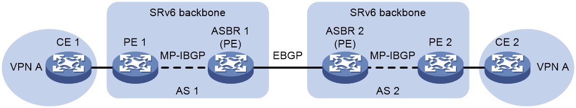
As illustrated in Figure 23, in the VPN-to-VPN connection networking method, the ASBR devices of the two AS connect directly. Both ASBRs act as PEs, treating each other as their own CE devices. They advertise conventional IPv4/IPv6 unicast routes to the opposite end via EBGP sessions.
The advantage of the VPN-to-VPN connection method is simplicity, where no special configuration is needed for inter-AS transitions between two ASBRs. The downside is poor scalability: ASBRs have to manage the routing of all VPNs, create a VPN-instance for each VPN, leading to an overly large number of VPN routes on the ASBR; also, each cross-AS VPN needs to be individually associated with an interface on the ASBR, increasing the requirement on the ASBR device.
Figure 23 Schematic Diagram of the VPN-to-VPN Connection Method
Implementation process of VPN-to-VPN connection
|
|
NOTE: · The implementation methods for IP L3VPN/EVPN L3VPN/EVPN VPWS/EVPN VPLS over SRv6 across ASs are consistent . This document illustrates it using the example of IP L3VPN over SRv6 inter-AS implementation . · In the networking of multi-AS VPN based on SRv6, types of advertisement and forwarding processes for various SRv6 SID classes are illustrated below, for instance, the End.DT4 SID. · The implementation process for both IPv4 over SRv6 multi-AS VPN and IPv6 over SRv6 multi-AS VPN is similar. The following text will illustrate this using IPv4 over SRv6 multi-AS VPN as an example. · In the network of VPN-to-VPN connections, within the AS, the packet forwarding method is the same as that of non-inter-AS networking. Between ASs, the packet forwarding methods based on SRv6 BE and SRv6 TE are the same. Therefore, we will use SRv6 BE as an example to explain the route advertisement and packet forwarding process of VPN-to-VPN connection methods. |
The route advertisement and packet forwarding process for VPN-to-VPN connection methods is as shown in Figure 24.
Figure 24 VPN-to-VPN connection method
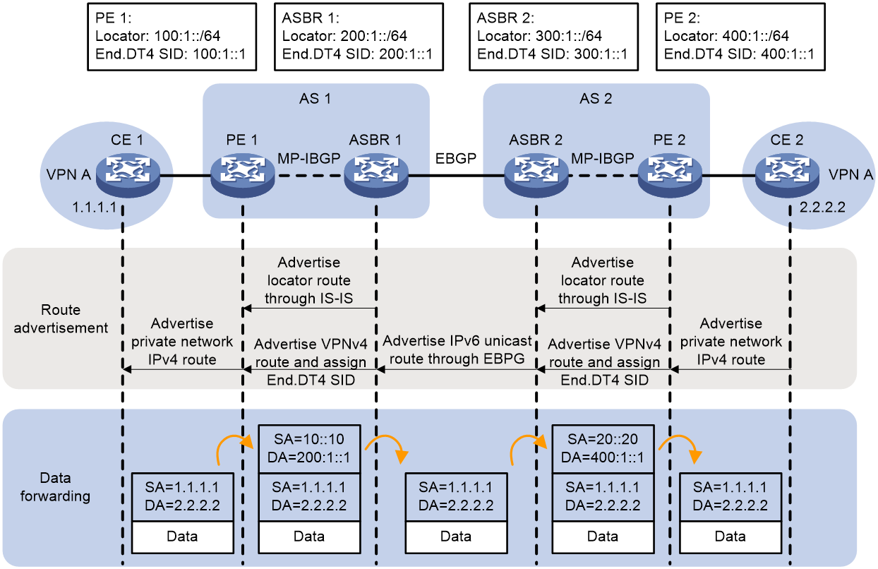
Within the AS, the PE needs to distribute the route of the network segment that contains the End.DT4 SID to all devices in the public network using the IGP protocol. For example, in AS 2, PE 2 advertises the route of the network segment (400:1::/64) that contains the End.DT4 SID to the devices within the AS (P and ASBR devices) using the IGP protocol (for example, IS-IS).
The process of advertising the private network route from CE 2 to CE 1 is as follows:
1. CE 2 uses IGP or BGP to advertise the private network route 2.2.2.2/32 of this site to PE 2.
2. After learning the private network routing information from CE 2, PE 2 stores this information in the routing table of VPN-instance A. PE 2 adds RD and RT attributes to the private network routing, and assigns End.DT4 SID 400:1::1 to it, forming a VPNv4 route. PE 2 then advertises the VPNv4 route to ASBR 2 via MP-IBGP.
3. ASBR 2 compares the Route Target attributes, learns the VPN routes advertised by PE 2 into the corresponding VPN-instance routing table, and then advertises them as IPv4 unicast routes to its CE device, namely ASBR 1, through EBGP session.
4. Upon receiving the IPv4 unicast routing from its CE (ASBR 2), ASBR 1 adds it to the routing table of the VPN-instance bound to the interface that received the route. ASBR 1 adds RD and RT attributes to the route, and allocates End.DT4 SID 200:1::1 for the private network route, forming a VPNv4 route. ASBR 1 then advertises the VPNv4 route to PE 1 via MP-IBGP.
5. Upon receiving the VPNv4 route, PE 1 adds it to the routing table of VPN instance A. It then translates the VPNv4 route into an IPv4 route and advertises it to CE 1.
6. After receiving the route, CE 1 learns it into the routing table.
After the route advertisement is completed, the process of forwarding the packet with a destination address of 2.2.2.2 from CE 1 to CE 2 is as follows:
1. CE 1 transmits an IPv4 packet with a destination address of 2.2.2.2 to PE 1.
2. After PE1, which is tied to VPN-instance A, receives a private network packet from the interface, it looks up a match for 2.2.2.2 in the routing table of VPN-instance A. It finds the corresponding End.DT4 SID 200:1::1 and then encapsulates the packet with an IPv6 header. The source address in the IPv6 header is manually configured by the administrator, and the destination address is End.DT4 SID 200:1::1.
3. PE 1 searches the IPv6 routing table based on End.DT4 SID 100:1::1, and forwards the packet to ASBR 1 via the optimal IGP route within AS 1.
4. After ASBR 1 receives a packet with the destination IPv6 address of End.DT4 SID 200:1::1, it performs decapsulation to remove the IPv6 packet header. Then, it matches the End.DT4 SID with VPN-instance A, looks up the routing table of VPN-instance A, and transmits the packet to ASBR 2.
5. Upon receiving a private network packet on
an interface bound with VPN-instance A, ASBR 2 searches for a matching 2.2.2.2
route in the routing table of VPN-instance A. It finds the corresponding
End.DT4 SID 400:1::1, then encapsulates the packet with an IPv6 header. The
source address in the IPv6 header is manually configured by an administrator,
and the destination address is End.DT4 SID 400:1::1.
6. ASBR 2 forwards the packet to PE 2 through the optimal IGP route within AS 2, based on the IPv6 routing table corresponding to End.DT4 SID 400:1::1.
7. After receiving a packet with the target IPv6 address as End.DT4 SID 400:1::1, PE 2 performs decapsulation to remove the IPv6 packet header. It then matches End.DT4 SID to VPN-instance A and looks up the routing table of VPN-instance A, before transmitting the packet to CE 2.
MP-EBGP connection method
About the MP-EBGP connection method
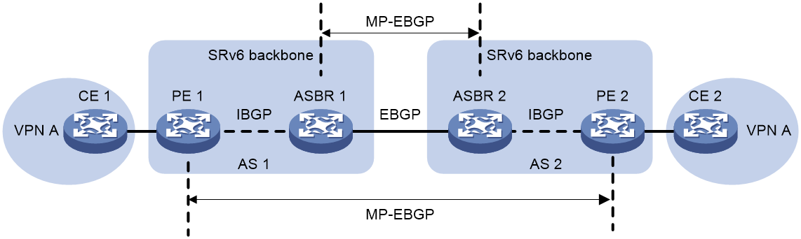
As shown in Figure 25, there are two support methods to establish a MP-EBGP connection:
· Two ASBRs exchange VPNv4/VPNv6/EVPN routes that they receive from the PE of their respective AS via MP-EBGP.
· A multi-hop MP-EBGP session is established between PEs of different ASs, and routes are advertised directly between PEs through this session.
Both types of MP-EBGP establishment methods support the following packet forwarding methods:
· SRv6 BE forwarding method: By advertising Locators of PEs in different ASs via the routing protocol, packets are forwarded through the shortest path calculated by the routing protocol, both within and between ASs.
· SRv6 TE forwarding method: The construction of a cross-AS SRv6 TE Policy, which consists of a list of SIDs derived from intra-AS SRv6 SIDs and inter-AS SRv6 BGP EPE SIDs.
Figure 25 MP-EBGP connection method
Implementation process of SRv6 BE forwarding in MP-EBGP connection mode
The process of route advertisement and packet forwarding using SRv6 BE forwarding method under the MP-EBGP connection mode is shown in Figure 26.
Figure 26 SRv6 BE forwarding in MP-EBGP connection mode
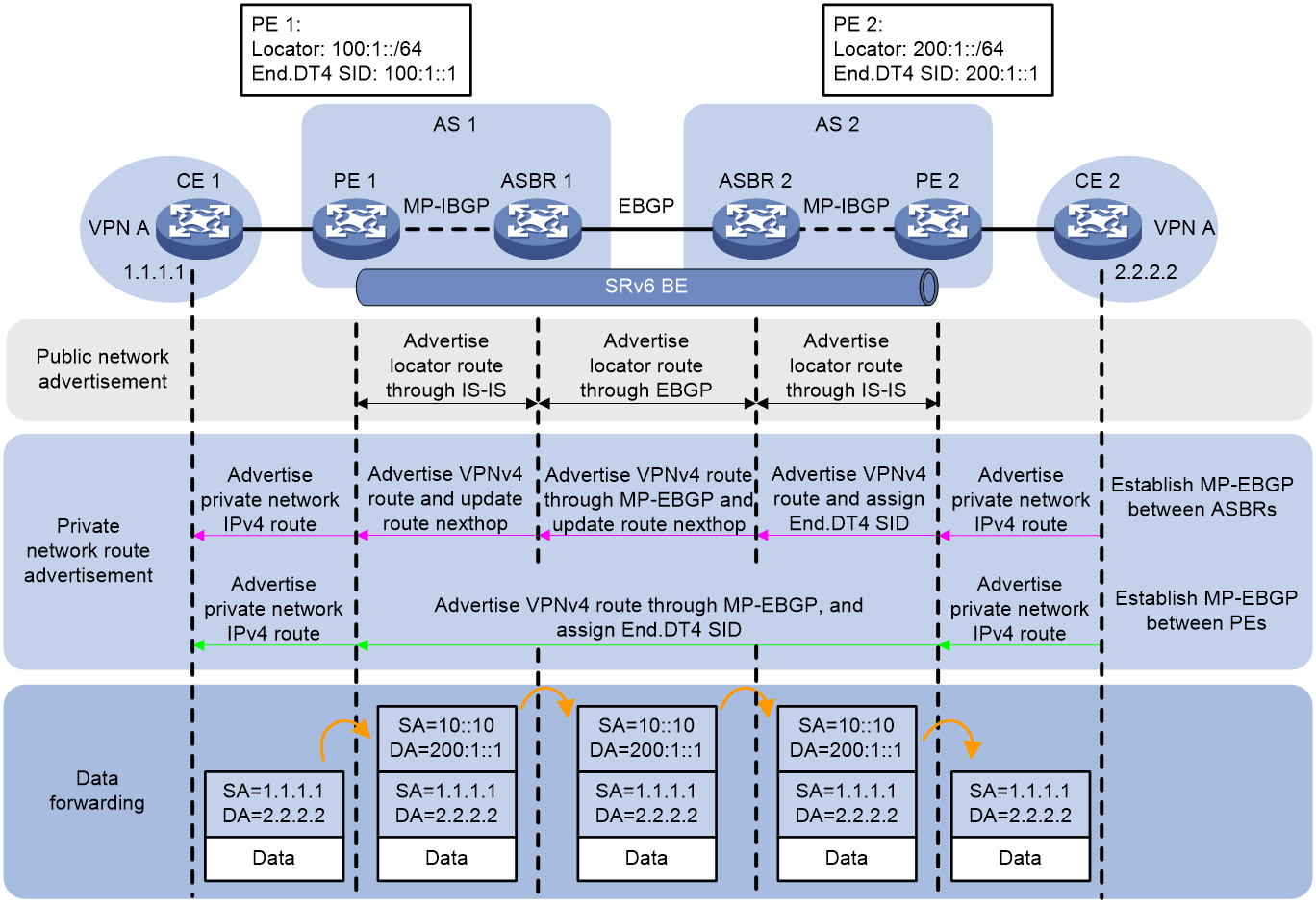
In the network configuration using MP-EBGP connection, it is necessary to advertise the route of the network segment to which the End.DT4 SID belongs across the AS. Taking the orientation from PE 2 to PE 1 as an example, PE 2 advertises the route of the network segment 200:1::/64, which the End.DT4 SID belongs to, to P and ASBR devices in the AS via IGP protocol (using IS-IS route as an example). ASBR 2 passes this network segment route 200:1::/64 to ASBR 1 via EBGP, while updating the next-hop address to the local host address of ASBR 2. ASBR 1 then advertises the network segment route 200:1::/64 to PE 1 through IGP protocol (using IS-IS route as an example).
In the MP-EBGP scenario between ASBRs, the process of advertising CE 2's private network routes to CE 1 is as follows:
1. CE 2 uses IGP or BGP to advertise the private network route 2.2.2.2/32 of this site to PE 2.
2. After learning the private network routing information from CE 2, PE 2 stores this information into the routing table of the VPN-instance A. PE 2 adds RD and RT attributes to the private network route, assigns End.DT4 SID 200:1::1 to it, and forms VPNv4 route. PE 2 then advertises the VPNv4 route to ASBR 2 via MP-IBGP.
3. Upon receiving the VPNv4 routes advertised by PE 2, ASBR 2 advertises them to ASBR 1 via MP-EBGP. ASBR 2 updates the next hop of the route to its own address during advertisement..
4. Upon receiving the VPNv4 route advertised by ASBR 2, ASBR 1 advertises the VPNv4 route to PE 1 via MP-IBGP. When ASBR 1 advertises the route, the next hop of the route is updated to the local host address.
5. Upon receiving the VPNv4 route, PE 1 adds it to the routing table of VPN-instance A and then advertises the VPNv4 route as an IPv4 route to CE 1.
6. Upon receiving the route, CE 1 adds it to the routing table.
In the MP-EBGP scenario established between PEs, the process of advertising CE 2's private network routes to CE 1 is as follows:
1. CE 2 uses IGP or BGP to advertise the private network route 2.2.2.2/32 of this site to PE 2.
2. After PE 2 learns the private network routing information from CE 2, it stores the private network route in the routing table of VPN-instance A. PE 2 adds RD and RT attributes to the private network route and allocates End.DT4 SID 200:1::1 to the private network route, forming the VPNv4 route. PE 2 then advertises the VPNv4 route to PE 1 through MP-EBGP.
3. After receiving the VPNv4 route, PE 1 adds it to the routing table of VPN-instance A, and advertises the VPNv4 route as an IPv4 route to CE 1.
4. Upon receiving the route, CE 1 learns it and incorporates it into the routing table.
After the route advertisement is completed, the forwarding process of the packet with the destination address of 2.2.2.2 from CE 1 to CE 2 is as follows:
1. CE 1 transmits an IPv4 packet with the destination address of 2.2.2.2 to PE 1.
2. After PE 1 receives a private network packet from an interface bound to VPN-instance A, it looks up the route matching 2.2.2.2 in the routing table of VPN-instance A, and finds the corresponding End.DT4 SID 200:1::1. Then, it encapsulates the IPv6 packet header for the packet. The source address in the IPv6 packet header is manually configured by the administrator, and the destination address is End.DT4 SID 200:1::1.
3. PE 1 looks up the IPv6 routing table according to End.DT4 SID 200:1::1, and forwards the packet to ASBR 1 through the optimal IGP route within AS 1.
4. After receiving the packet, ASBR 1 looks up the routing table based on the destination address in the IPv6 header, and forwards the packet to ASBR 2.
5. Upon receiving the packet, ASBR 2 looks up the IPv6 routing table based on End.DT4 SID 200:1::1, and passes the packet to PE 2 through the optimal IGP route.
6. Upon receiving a packet with the destination IPv6 address End.DT4 SID 200:1::1, PE 2 performs decapsulation to remove the IPv6 header. It then matches the End.DT4 SID with VPN-instance A, looks up the routing table for VPN-instance A, and transmits the packet to CE 2.
Implementation process of SRv6 TE forwarding in MP-EBGP connection mode
In the MP-EBGP connection mode, the route advertisement and packet forwarding process using SRv6 TE forwarding method is shown in Figure 27. In this network, the controller sends SRv6 TE Policy related configurations to PE 1.
Figure 27 SRv6 TE forwarding in MP-EBGP connection mode
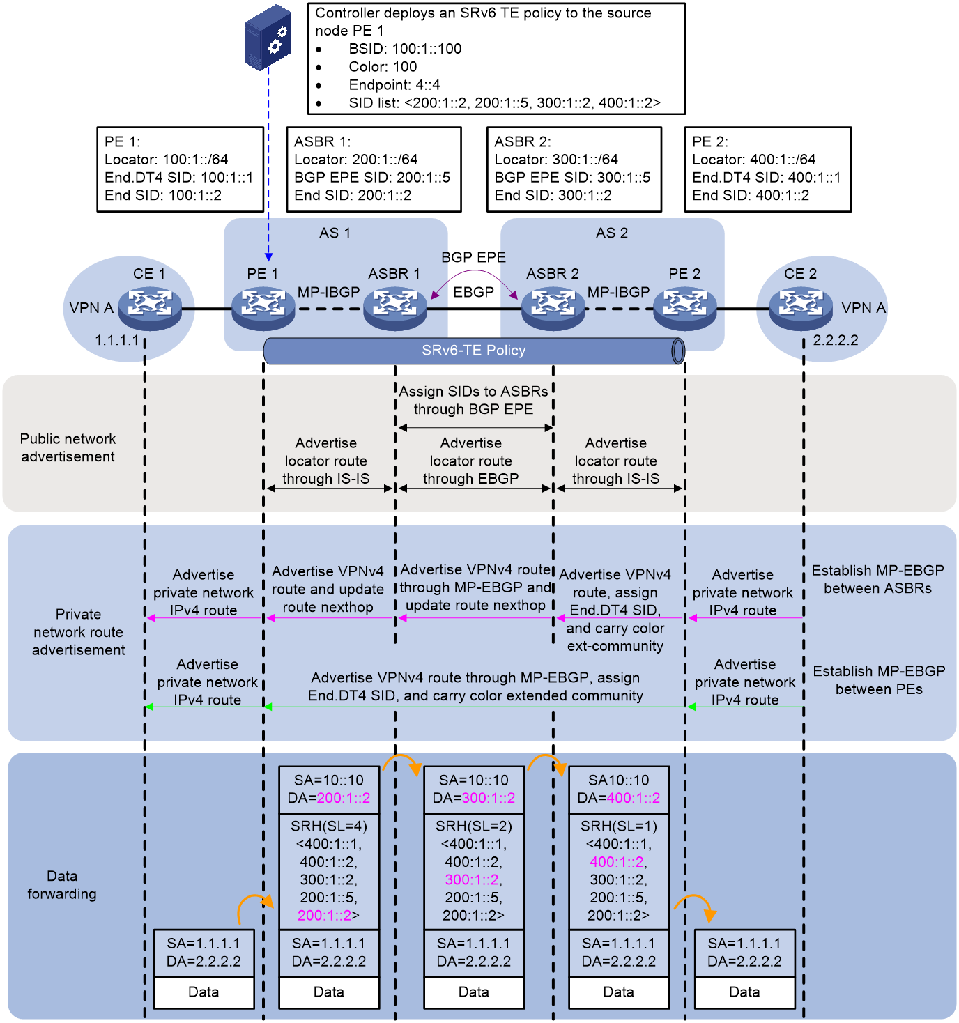
In the network created using the MP-EBGP connection method, establishing an MP-EBGP scenario between ASBRs requires the route of the network segment that the End.DT4 SID belongs to, to cross AS and be advertised. Taking the PE 2 -> PE 1 direction as an example, PE 2 advertises the route of the network segment (400:1::/64) belonging to End.DT4 SID to internal P and ASBR devices, using the IGP protocol (with IS-IS route as an example). ASBR 2 then advertises the same network segment route to ASBR 1 through EBGP, and simultaneously updates the next-hop address to the local host address of ASBR 2. Finally, ASBR 1 advertises the network segment route (400:1::/64) to PE 1 using the IGP protocol (also using IS-IS route as an example).
Within AS 1 and AS 2, each device uses the IGP protocol (IS-IS as an example) to advertise the route of the network segment of their respective End SID's Locator.
BGP EPE needs to be deployed between ASs, and BGP EPE SID should be allocated to ASBR.
· ASBR 1 allocates BGP EPE SID 200:1::5 to ASBR 2, with the corresponding next hop being ASBR 2.
· ASBR 2 allocates BGP EPE SID 300:1::5 to ASBR 1, with the next hop corresponding to this SID being ASBR 1.
In the MP-EBGP scenario between ASBRs, taking Color-based traffic steering as an example, the process of advertising CE 2's private network routes to CE 1 is as follows:
1. CE 2, utilizing IGP or BGP, advertises the private network route 2.2.2.2/32 of this site to PE 2.
2. After PE 2 learns the private network routing information from CE 2, it stores the private network routes in the routing table of VPN-instance A. PE 2 then adds RD and RT attributes to the private network routes and assigns the End.DT4 SID 400:1::1, forming a VPNv4 route. PE 2 advertises the VPNv4 route, which carries the End.DT4 SID and Color extended community attribute, to ASBR 2 via MP-EBGP.
3. Upon receiving the VPNv4 route advertised by PE 2, ASBR 2 passes it to ASBR 1 via MP-EBGP. When ASBR 2 advertises the route, it updates the next hop as its local host address.
4. Upon receiving the VPNv4 route advertised by ASBR 2, ASBR 1 propagates it to PE 1 via MP-IBGP. When ASBR 1 advertises the route, it updates the next hop as its local host address.
5. After receiving the VPNv4 route, PE 1 adds it to the routing table of VPN instance A. Simultaneously, the BGP route is iteratively directed to the SRv6 TE Policy using the Color diversion method. PE 1 then translates the VPNv4 route into an IPv4 route and advertises it to CE 1.
6. After receiving the route, CE 1 learns it into the {routing table}.
In the scenario of establishing MP-EBGP between PEs, taking the Color diversion method as an example, the process of CE 2 advertising its private network route to CE 1 is as follows:
1. CE 2 uses IGP or BGP to advertise the private network route 2.2.2.2/32 of this site to PE 2.
2. After learning the private network routing information from CE 2, PE 2 stores the private network route in the routing table of VPN-instance A. PE 2 enhances the private network route with RD and RT attributes, and allocates End.DT4 SID 400:1::1 to the private network route, forming a VPNv4 route. PE 2 advertises the VPNv4 route which carries the End.DT4 SID and Color extended community attribute to PE 1 through MP-EBGP.
3. After receiving the VPNv4 route, PE 1 adds it to the routing table of VPN instance A, and the BGP route is iterated to the SRv6 TE Policy using the Color diversion method. PE 1 translates the VPNv4 route into an IPv4 route and advertises it to CE 1.
4. Upon receiving the route, CE 1 learns it and incorporates it into the routing table.
After the completion of the route advertisement, the forwarding process of packets with a destination address of 2.2.2.2 from CE 1 to CE 2 is as follows:
1. CE 1 transmits an IPv4 packet with a destination address of 2.2.2.2 to PE 1.
2. Upon receiving a private network packet from an interface bound to VPN-instance A, PE 1 searches in the routing table of VPN-instance A for a route matching 2.2.2.2. It finds the corresponding End.DT4 SID 400:1::1, and the next hop for this route is SRv6 TE Policy. PE 1 then adds an SRH to the packet, encapsulates the SID List of the SRv6 TE Policy <200:1::2, 200:1::5, 300:1::2, 400:1::2> and End.DT4 SID 400:1::1, followed by encapsulation of IPv6 basic header information. Once completed, the packet is forwarded to ASBR 1.
3. After receiving the packet, ASBR 1 executes the following operations:
¡ Search the Local SID table with the IPv6 destination address 200:1::2 from the packet, match it to the End SID, decrease the packet's SL by 1, and update the IPv6 destination address to 200:1::5.
¡ Use the IPv6 destination address 200:1::5 to look up the Local SID table. Then, match it with the BGP EPE SID and execute the corresponding forwarding action. That is, forward the packet from the specified interface to ASBR 2, meanwhile reduce SL by 1, and update the IPv6 destination address to 300:1::2.
4. After receiving the packet, ASBR 2 performs the following operations:
¡ The packet's IPv6 destination address, 300:1::2, is used to search the Local SID table, where it matches the End SID. The packet's SL is then reduced by 1, and the IPv6 destination address is updated to 400:1::2.
¡ Look up the routing table according to the destination address in the IPv6 header, and forward the packet to PE 2.
5. Upon receiving the packet, PE 2 performs the following operations:
¡ The IPv6 destination address of the packet is used to search the Local SID table. If the End SID is matched, the SL of the packet is decreased by 1. The IPv6 destination address is then updated to be the End.DT4 SID 400:1::1.
6. Use the destination address 400:1::1 to search the Local SID table, match the End.DT4 SID, and execute the corresponding forwarding action of End.DT4 SID. That is, perform decapsulation to remove the IPv6 header, and match VPN-instance A with the End.DT4 SID. Then, search the routing table of VPN-instance A, and transmit the packet to CE 2.
SRv6 interworking
SRv6 interworking refers to the situation where user packets need to be transmitted across both SRv6 and MPLS networks, meaning there is interoperability between the SRv6 network and the MPLS network.
L3VPN over SRv6 interworking
About L3VPN over SRv6 interworking.
When the backbone network carrying VPNv4/VPNv6/EVPN routes spans SRv6 and MPLS networks, interoperability between SRv6 and MPLS networks can be achieved through L3VPN over SRv6 Interworking.
Based on the advertised route class, L3VPN over SRv6 Interworking is divided into:
· IP L3VPN over SRv6 Interworking
· EVPN L3VPN over SRv6 Interworking
Based on the network type, L3VPN over SRv6 Interworking is divided into the following categories:
· L3VPN over SRv6 Interworking within the AS: In the same AS, different public networks are used to carry VPNv4/VPNv6/EVPN routes, which means that some PEs are deployed with MPLS network, and some PEs are deployed with SRv6 network.
· Inter-AS L3VPN over SRv6 Interworking: The backbone network spans multiple different ASs, some ASs have MPLS network deployment, and some ASs have SRv6 network deployment.
The inter-AS L3VPN over SRv6 Interworking supports the following implementation methods:
¡ Interworking of L3VPN over SRv6 Option A.
¡ Interworking of L3VPN over SRv6 using Option B.
|
|
NOTE: In the network configuration of L3VPN over SRv6 Interworking, the processing methods for route advertisement and packet forwarding in both IP L3VPN over SRv6 Interworking and EVPN L3VPN over SRv6 Interworking are similar, as are the methods used for IPv4 private network access and IPv6 private network access. The following text will only use IPv4 L3VPN over SRv6 Interworking as an example to illustrate. |
Intra-AS L3VPN over SRv6 interworking
About intra-AS L3VPN over SRv6 interworking
In intra-AS L3VPN over SRv6 interworking, different PEs use different forwarding methods (SRv6 or MPLS) in the same AS. As depicted in Figure 28, when using the public network to carry L3VPN private network data, the private network data needs to traverse the SRv6 network and the MPLS network.
Figure 28 Diagram of intra-AS L3VPN over SRv6 interworking.
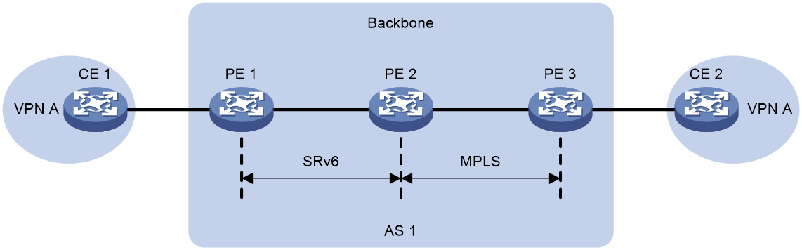
Implementation process of intra-AS L3VPN over SRv6 interworking
The advertisement and packet forwarding process of intra-AS L3VPN over SRv6 interworking route is shown as depicted in Figure 29.
Figure 29 Implementing intra-AS L3VPN over SRv6 interworking
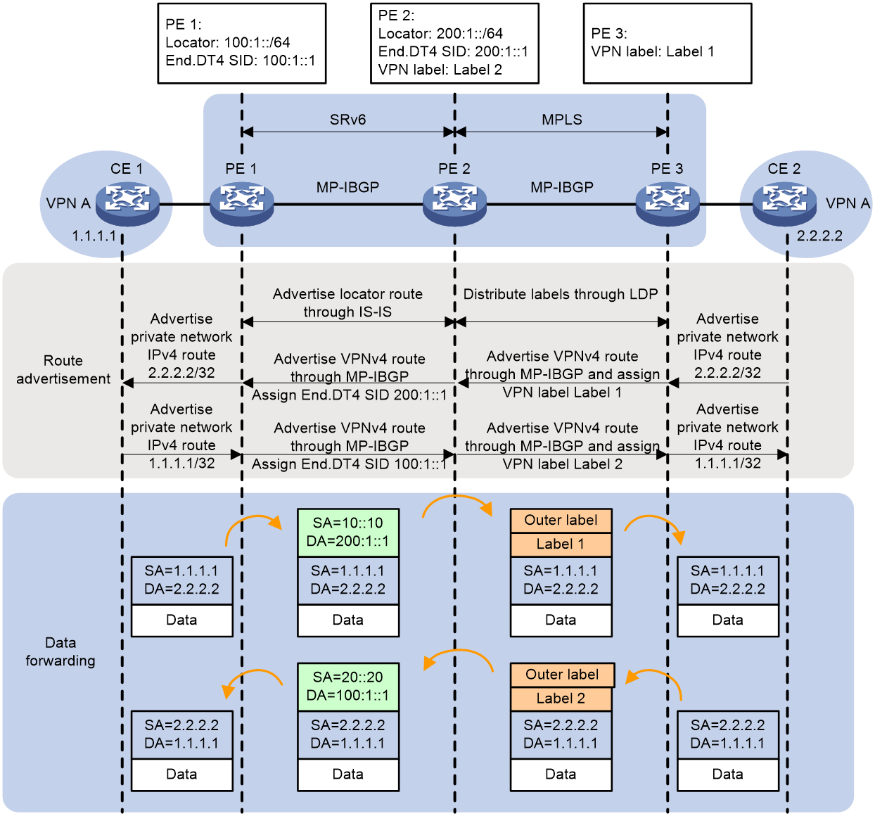
Within an AS, it is necessary for PE devices to advertise the route of the network segment belonging to End.DT4 SID to all devices in the public network through the IGP protocol. For example, PE 1 passes the route of the network segment 100:1::/64 that belongs to End.DT4 SID to the device PE 2 within the AS through the IGP protocol (taking IS-IS route as an example).
The process of advertising the private network route 2.2.2.2/32 from CE 2 to CE 1 is as follows:
1. CE 2 uses IGP or BGP to advertise the private network route 2.2.2.2/32 of the local site to PE 3.
2. After learning the private network routing information from CE 2, PE 3 stores it in the routing table of VPN-instance A. PE 3 adds RD and RT attributes to the private network route and assigns the inner layer private network label Label 1 to it, through MP-BGP, thus forming the VPNv4 route. PE 3 advertises the VPNv4 route to PE 2 via MP-IBGP.
3. Upon receiving the VPNv4 route advertised by PE 3, PE 2 passes the VPNv4 route to PE 1 through MP-IBGP. When PE 2 advertises this route, it changes the next-hop address to its own address, allocates End.DT4 SID 200:1::1 to the route, and establishes a link between the End.DT4 SID and MPLS label Label 1.
4. After receiving a VPNv4 route, PE 1 adds it to the routing table of VPN-instance A and translates the VPNv4 route into an IPv4 route, which is then advertised to CE 1.
5. Upon receiving the route, CE 1 learns and adds it to the routing table.
The process of advertising the private network route 1.1.1.1/32 to CE 1 is as follows:
1. CE 1 uses IGP or BGP to advertise the private network route 1.1.1.1/32 of this site to PE 1.
2. After PE 1 learns the private network routing information from CE 1, it stores the private network routes in the routing table of VPN-instance A. PE 1 adds RD and RT attributes to the private network routes and assigns an End.DT4 SID 100:1::1 through MP-BGP, forming a VPNv4 route. PE 1 then advertises the VPNv4 route to PE 2 via MP-IBGP.
3. Upon receiving the VPNv4 route advertised by PE 1, PE 2 passes the route to PE 3 via MP-IBGP. When PE 2 advertises this route, it changes the next-hop address of the route to its own address, assigns the route a private network label 'Label 2', and establishes a connection between End.DT4 SID and MPLS label 'Label 2'.
4. After PE 3 receives the VPNv4 route, it adds this route to the routing table of VPN-instance A, and then translates the VPNv4 route into an IPv4 route for advertisement to CE 2.
5. After receiving the route, CE 2 learns it into the routing table.
Upon completion of the route advertisement, the process of forwarding the packets with the destination address 2.2.2.2 from CE 1 to CE 2 is as follows:
1. CE 1 transmits an IPv4 packet with a destination address of 2.2.2.2 to PE 1.
2. After PE 1 receives a private network packet from an interface bound with 'VPN-instance' A, it looks up the route matching 2.2.2.2 in the routing table of 'VPN-instance' A. Upon finding the corresponding End.DT4 SID 200:1::1, it encapsulates the packet with an IPv6 packet header and transmits the packet to PE 2 via SRv6 BE or SRv6 TE.
3. After receiving the packet, PE 2 decapsulates it by removing the IPv6 header, based on the correlation between the End.DT4 SID and MPLS label Label 1. It then encapsulates the packet with the private network label Label 1 and the public network label between PE 2 and PE 3, before forwarding the packet to PE 3.
4. After receiving the packet, PE 3 matches the private network label with VPN-instance A, searches for the routing table of VPN-instance A, removes the private network label, and then transmits the packet to CE 2.
After the route advertisement is completed, the forwarding process of the packet with the destination address of 1.1.1.1 from CE 2 to CE 1 is as follows:
1. CE 2 transmits an IPv4 packet with the destination address of 1.1.1.1 to PE 3.
2. Upon receipt of a private network packet from an interface bound to the VPN-instance A, PE 3 looks up a route matching 1.1.1.1 in the routing table of the VPN-instance A. It then finds the corresponding private network label Label 2, encapsulates the packet with the private network label and the public network label between PE 2 and PE 3, and transmits the packet to PE 2.
3. Upon receiving the packet, PE 2, based on the association between End.DT4 SID and MPLS tag Label 2, performs decapsulation to remove the private network tag. It then encapsulates the packet with End.DT4 SID 100:1::1, and transmits it to PE 1 via the SRv6 BE or SRv6 TE method.
4. Upon receiving the packet, PE 1 performs decapsulation to remove the IPv6 packet header. Using the End.DT4 SID 100:1::1, it matches VPN-instance A and checks its routing table. The packet is then transmitted to CE 2.
L3VPN over SRv6 Option A interworking
About L3VPN over SRv6 Option A interworking
As shown in Figure 30, an SRv6 network is deployed in AS 1, while an MPLS network is deployed in AS 2, within the context of L3VPN over SRv6 Option A Interworking network configuration. Private network packets need to be forwarded across AS 1 and AS 2. The two ASBR devices are directly connected. Each ASBR acts as a PE, treating the other as its own CE device, and advertises standard IPv4/IPv6 unicast routes to the opposite end via EBGP sessions.
Figure 30 L3VPN over SRv6 Option A Interworking
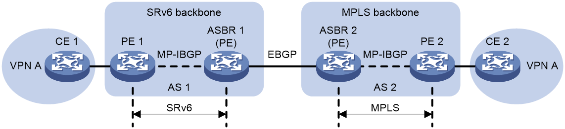
Implementation process of L3VPN over SRv6 Option A Interworking
Figure 31 shows the L3VPN over SRv6 Option A Interworking route advertisement and packet forwarding process.
Figure 31 L3VPN over SRv6 Option A Interworking.
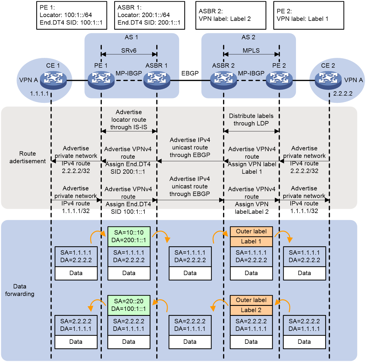
Within the Autonomous System (AS) deploying the SRv6 network, the PE and ASBR need to advertise the route of the Locator belonging to the End.DT4 SID to all devices within the AS via the IGP protocol. For example, PE 1 advertises the route of the Locator 100:1::/64 belonging to the End.DT4 SID to the P and ASBR devices within the AS via the IGP protocol (using IS-IS route as an example).
The process of advertising the private network route 2.2.2.2/32 from CE 2 to CE 1 is as follows:
1. CE 2 uses IGP or BGP to advertise the private network route 2.2.2.2/32 of this site to PE 2.
2. After PE 2 learns the private network routing information from CE 2, it stores the private network routes in the routing table of VPN-instance A. PE 2 adds RD and RT attributes to the private network routes, and assigns an inner private network label, Label 1, to the private network routes through MP-BGP, forming a VPNv4 route. PE 2 then advertises the VPNv4 route to ASBR 2 via MP-IBGP.
3. ASBR 2 compares the Route Target attributes, learns the VPN routes advertised by PE 2 into the corresponding VPN-instance routing table, and converts the VPNv4 routing into IPv4 unicast routing. Through EBGP sessions, it then broadcasts the IPv4 unicast route to its CE device, which is ASBR 1.
4. After ASBR 1 receives IPv4 unicast routing from its CE (ASBR 2), it adds the routing to the routing table of the VPN-instance bound to the interface that received the routing. ASBR 1 adds RD and RT attributes to the routing and allocates End.DT4 SID 200:1::1 to the private network routing, forming a VPNv4 route. ASBR 1 then advertises the VPNv4 route to PE 1 via MP-IBGP.
5. Upon receiving the VPNv4 route, PE 1 adds the route to the routing table of VPN instance A and advertises the VPNv4 route as an IPv4 route to CE 1.
6. After receiving the route, CE 1 learns it into the routing table.
The process of advertising private network route 1.1.1.1/32 from CE 1 to CE 2 is as follows:
1. CE 1 uses IGP or BGP to advertise the private network route 1.1.1.1/32 of this site to PE 1.
2. After learning the private network routing information from CE 1, PE 1 stores the private network route in the routing table of VPN instance A. PE 1 enhances the private network route with RD and RT attributes, and assigns End.DT4 SID 100:1::1 to the private network route through MP-BGP, forming a VPNv4 route. PE 2 then advertises the VPNv4 route to ASBR 1 via MP-IBGP.
3. ASBR 1 compares the Route Target attributes, learns the VPN routes advertised by PE 1 to the corresponding VPN-instance routing table, and translates VPNv4 routes into IPv4 unicast routes. Through the EBGP session, it advertises the IPv4 unicast route to its CE device, i.e., ASBR 2.
4. After receiving the IPv4 unicast routing from its CE (ASBR 1), ASBR 2 adds it to the routing table of the VPN-instance bound to the interface where the routing was received. ASBR 2 adds the RD and RT attributes to the routing, allocates the private network label 2 to the private network routing, forming a VPNv4 routing. ASBR 2 then advertises the VPNv4 routing to PE 2 via the MP-IBGP.
5. Upon receiving the VPNv4 route, PE 2 adds it to the routing table of VPN-instance A, and then converts and advertises the VPNv4 route to CE 2 as an IPv4 route.
6. Upon receiving the routes, CE 2 learns them and adds them to the routing table.
After the completion of the route advertisement, the forwarding process of the packet with a destination address of 2.2.2.2 from CE 1 to CE 2 is as follows:
1. CE 1 transmits an IPv4 packet with a destination address of 2.2.2.2 to PE 1.
2. Upon receiving a private network packet from an interface bound to VPN-instance A, PE 1 searches for a route matching 2.2.2.2 in VPN-instance A's routing table. It then finds the corresponding End.DT4 SID 200:1::1, encapsulates the packet with an IPv6 header, and transmits the packet to ASBR 1 through SRv6 BE or SRv6 TE.
3. Upon receiving a packet with the destination IPv6 address of End.DT4 SID 200:1::1, ASBR 1 decapsulates it by removing the IPv6 packet header. It then matches the End.DT4 SID with VPN-instance A, consults the routing table of VPN-instance A, and transmits the packet to ASBR 2.
4. After ASBR 2 receives a private network packet from the interface bound with VPN-instance A, it looks up the routing table of 'VPN-instance A' to find a match for 2.2.2.2, then encapsulates the packet with private network label 1 and the public network label between ASBR 2 and PE 2, and then transmits the packet to PE 2.
5. After receiving the packet, PE 2 matches the private network tag to VPN-instance A, searches the routing table of VPN-instance A, strips off the private network tag, and then transmits the packet to CE 2.
After the route advertisement, the forwarding process of packets with a destination address of 1.1.1.1 from CE 2 to CE 1 is as follows:
1. CE 2 transmits an IPv4 packet with a destination address of 1.1.1.1 to PE 2.
2. Upon receiving a private network packet from the interface bound with VPN-instance A, PE 2 searches for a route matching 1.1.1.1 in the routing table of VPN-instance A. It then encapsulates the packet with the private network label 2 and the public network label between ASBR 2 and PE 2, before transmitting the packet to ASBR 2.
3. Upon receiving the packet, ASBR 2 matches VPN-instance A according to the private network label 2, checks the routing table of VPN-instance A, and after stripping off the private network label, it transmits the packet to ASBR 1.
4. After ASBR 1 receives a private network packet from the interface bound with VPN-instance A, it looks for a route matching 1.1.1.1 in the routing table of VPN-instance A. It finds the corresponding End.DT4 SID 100:1::1, then encapsulates the packet with an IPv6 packet header, and transmits the packet to PE 1 through SRv6 BE or SRv6 TE method.
5. Upon receiving the packet, PE 1 performs decapsulation to remove the IPv6 packet header, and matches with VPN-instance A by End.DT4 SID 100:1::1, looks up the routing table of VPN-instance A, and transmits the packet to CE 2.
L3VPN over SRv6 Option B interworking
About L3VPN over SRv6 Option B interworking
As shown in Figure 32, in the L3VPN over SRv6 Option B interworking networks, an SRv6 network is deployed in AS 1, and an MPLS network is deployed in AS 2. Private network packets need to be forwarded across AS 1 and AS 2. The two ASBR devices are directly connected. The VPN routes received from each PE are exchanged between the ASBRs through MP-EBGP.
Figure 32 L3VPN over SRv6 Option B Interworking
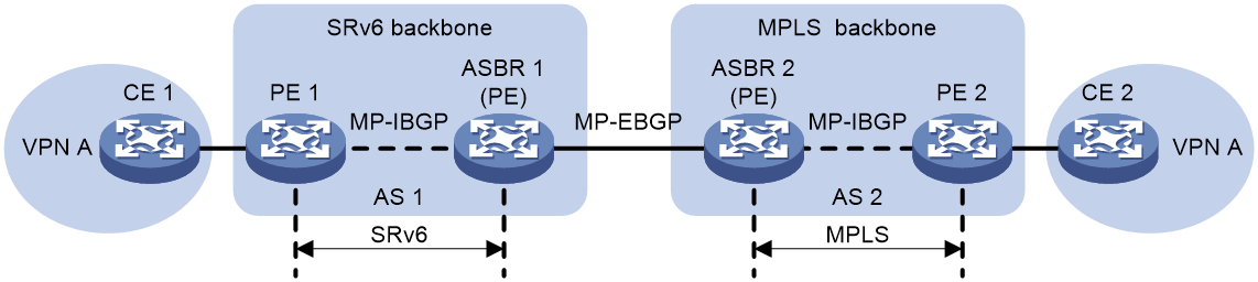
In the networking scenario of L3VPN over SRv6 Option B Interworking, when packets are forwarded from the SRv6 network to the MPLS network to enable interoperability, there needs to be an association between the SRv6 SID (that is, the IPv6 address) and the MPLS label. Since the ASBR in the SRv6 and MPLS networks does not have a VPN-instance and an interface associated with the VPN-instance, the ASBR in the SRv6 network cannot allocate the End.DT4 SID that identifies the VPN-instance in the private network routing. The ASBR in the MPLS network cannot learn the private network routing to the local VPN routing table, and will directly discard the packets during forwarding. Therefore, ASBRs in the SRv6 network must assign an SRv6 SID associated with a label for private network routes, known as End.T SID, and advertise the route of the Locator segment containing the End.T SID within the SRv6 network via the IGP protocol. The forwarding action corresponding to the End.T SID is to peel off the outer IPv6 header, and forward the packet by looking up the IPv6 FIB table according to the End.T SID.
Implementation process of L3VPN over SRv6 Option B interworking
Figure 33 shows the process of route advertisement and packet forwarding for L3VPN over SRv6 Option B Interworking.
Figure 33 L3VPN over SRv6 Option B Interworking
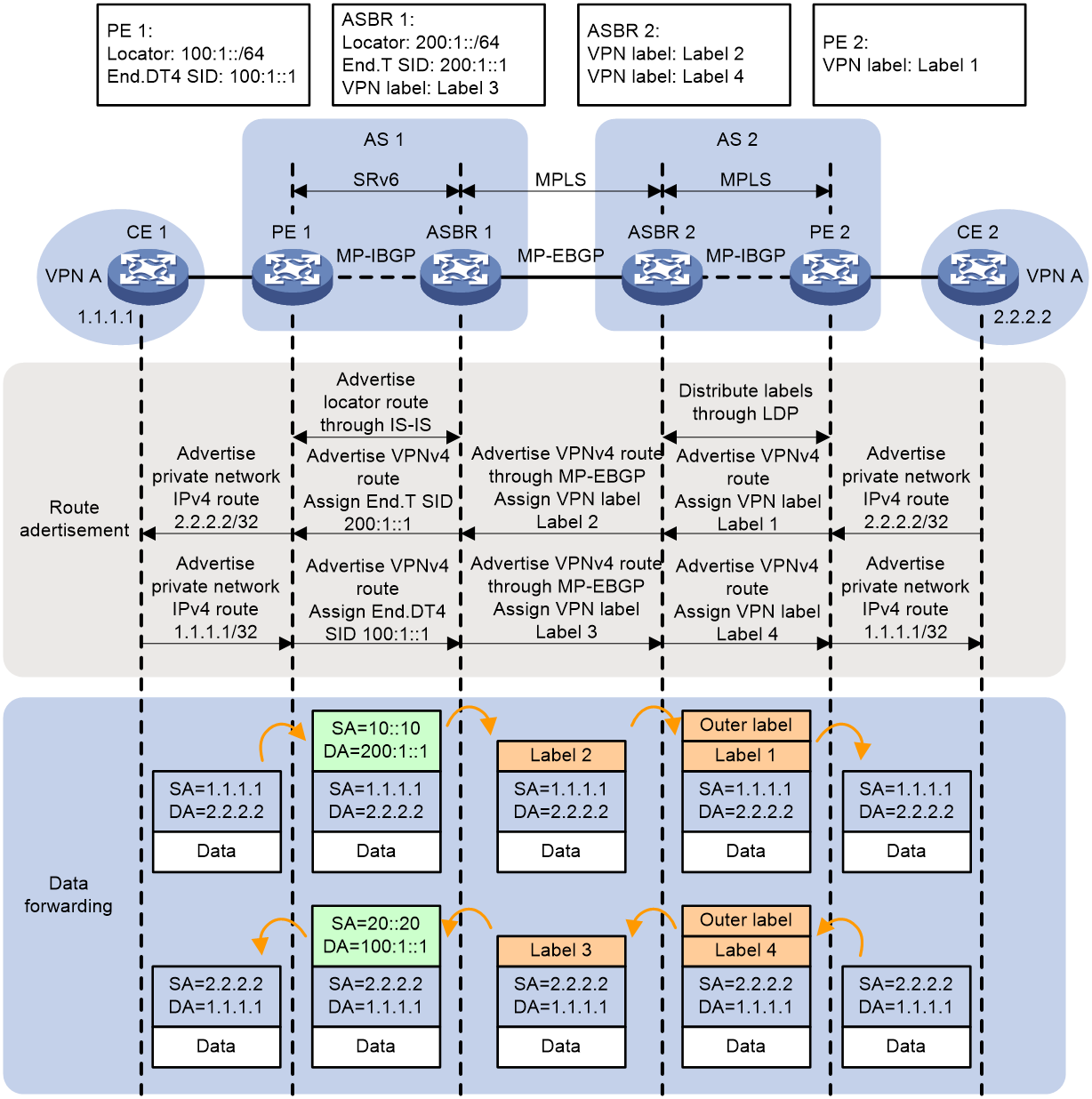
Within the AS deploying the SRv6 network, the route of the network segment Locator containing End.DT4 SID and End.T SID needs to be advertised to all devices within the AS through the IGP protocol between PE and ASBR. For instance, PE 1 passes the route of network segment Locator 100:1::/64 containing End.DT4 SID to the devices within the AS and ASBR utilizing the IGP protocol (IS-IS route as an example).
The process of the private network route 2.2.2.2/32 from CE 2 being advertised to CE 1 is as follows:
1. CE 2 uses IGP or BGP to advertise the private network route 2.2.2.2/32 of this site to PE 2.
2. After PE 2 learns the private network routing information from CE 2, it stores the private network routes into the routing table of VPN-instance A. PE 2 adds RD and RT attributes to the private network routes and MP-BGP allocates the inner private network label Label 1 to the private network routes, forming VPNv4 routes. PE 2 then advertises the VPNv4 routes to ASBR 2 via MP-IBGP.
3. Upon receiving the VPNv4 route advertised by PE 2, ASBR 2 passes it to ASBR 1 through MP-EBGP. When ASBR 2 advertises the route, it updates the next hop to its local host address, assigns a new MPLS label, Label 2, for the route, and establishes a link between MPLS label Label 2 and MPLS label Label 1.
4. After receiving the VPNv4 route advertised by ASBR 2, ASBR 1 passes the VPNv4 route to PE 1 through MP-IBGP. When ASBR 1 advertises the route, it updates the next hop as the local host address, allocates an End.T SID for the route, and establishes an association between the End.T SID and MPLS label Label 2.
5. After receiving the VPNv4 route, PE 1 adds it to the routing table of VPN-instance A, and then translates the VPNv4 route into an IPv4 route which is advertised to CE 1.
6. Upon receiving the route, CE 1 learns it into the routing table.
The process of advertising the private network route 1.1.1.1/32 from CE 1 to CE 2 is as follows:
1. CE 1 uses IGP or BGP to advertise the private network route 1.1.1.1/32 of this site to PE 1.
2. After PE 1 learns the private network routing information from CE 1, it stores the private network route in the routing table of VPN-instance A. PE 1 adds RD and RT attributes to the private network route, and MP-BGP allocates the End.DT4 SID 100:1::1 for the private network route, forming the VPNv4 route. PE 1 then advertises the VPNv4 route to ASBR 1 through MP-IBGP.
3. After ASBR 1 receives the VPNv4 route advertised by PE 2, it passes it to ASBR 2 via MP-EBGP. When ASBR 1 advertises the route, it updates the route's next hop to its local host address, assigns the private network label Label 3 to the route, and establishes a correlation between the private network label Label 3 and End.DT4 SID.
4. Upon receiving the VPNv4 route advertised by ASBR 1, ASBR 2 passes on the VPNv4 route to PE 2 via MP-IBGP. When ASBR 2 advertises the route, it updates the next hop to its local host address, allocates a private network label 4 to the route, and associates private network label 4 with private network label 3.
5. Upon receiving the VPNv4 route, PE 2 adds the route to the routing table of VPN-instance A, and advertises the VPNv4 route as an IPv4 route to CE 2.
6. Upon receiving the route, CE 2 learns it into the routing table.
After completing the route advertisement, the forwarding process of packets with a destination address of 2.2.2.2 from CE 1 to CE 2 is as follows:
1. CE 1 transmits an IPv4 packet with a destination address of 2.2.2.2 to PE 1.
2. Upon receiving a private network packet from an interface bound with VPN-instance A, PE 1 searches the routing table of VPN-instance A for a route that matches 2.2.2.2. Having found the corresponding End.T SID 200:1::1, it encapsulates the packet with an IPv6 header, then transmits the packet to ASBR 1 using either the SRv6 BE or SRv6 TE method.
3. After receiving the packet, ASBR 1 removes the outer IPv6 header, and forwards the packet according to the End.T SID by looking up the IPv6 FIB table. The outgoing label is Label 2. ASBR 1 then re-encapsulates the MPLS label Label 2 onto the packet, and forwards it to ASBR 2. The packets between ASBR 1 and ASBR 2 carry only a single layer of MPLS label.
4. ASBR 2 replaces MPLS label Label 2 with Label 1, adds the label of the public network tunnel from ASBR 2 to PE 2, and forwards the packet to PE 2.
5. After PE 2 receives the packet, it matches the private network tag to VPN-instance A, searches for the routing table of VPN-instance A, strips the private network tag, and then transmits the packet to CE 2.
After the route advertisement is completed, the process of forwarding a packet with a destination address of 1.1.1.1 from CE 1 to CE 2 is as follows:
1. CE 2 transmits an IPv4 packet with the destination address of 1.1.1.1 to PE 2.
2. After receiving a private network packet from an interface bound with VPN-instance A, PE 2 searches for a route matching 1.1.1.1 in the routing table of VPN-instance A. PE 2 then encapsulates the packet with a private network label (Label 4) and a public network label between ASBR 2 and PE 2, and transmits the packet to ASBR 2.
3. After receiving the packet, ASBR 2 strips the public network label, replaces the private network label, Label 4, with Label 3, and transmits the packet to ASBR 1. The packets between ASBR 1 and ASBR 2 carry only one layer of private network label.
4. Upon receiving the packet, ASBR 1 replaces the private network label Label 3 with End.DT4 SID 100:1::1, and then it transmits the packet to PE 1 via either SRv6 BE or SRv6 TE.
5. After receiving the packet, PE 1 performs decapsulation to remove the IPv6 header and matches VPN-instance A based on the End.DT4 SID 100:1::1. It then searches the routing table of VPN-instance A and transmits the packet to CE 2.
L2VPN over SRv6 interworking
When the backbone network carrying EVPN routes spans across SRv6 and MPLS networks, interoperability between SRv6 and MPLS networks can be achieved via L2VPN over SRv6 Interworking.
When the MPLS network is an MPLS L2VPN network or VPLS network, the intercommunication between the SRv6 network and the MPLS network can be achieved by accessing the SRv6 PW function through LDP PW or static PW.
When the MPLS network is an EVPN VPWS network or an EVPN VPLS network, the intercommunication between the SRv6 network and the MPLS network can be achieved in the following ways:
· Intra-AS L2VPN over SRv6 Interworking: Within the same AS, different public networks are used to carry EVPN routes, that is, MPLS network is deployed between some PEs, and SRv6 network is deployed between other PEs.
· Inter-AS L2VPN over SRv6 Interworking: The backbone network spans several different Autonomous Systems (AS), with some AS deploying MPLS networks and others deploying SRv6 networks. The support for the following implementation methods is provided by Inter-AS L2VPN over SRv6 Interworking:
¡ L2VPN over SRv6 Option A Interworking
¡ L2VPN over SRv6 Option B Interworking
|
|
NOTE: In the networking scenarios of intra-AS L2VPN over SRv6 Interworking and L2VPN over SRv6 Option B Interworking, in order to achieve interoperability when packets are forwarded from the SRv6 network to the MPLS network, a SRv6 SID (i.e., IPv6 address) needs to be associated with the MPLS label. Since the boundary devices of the SRv6 network and MPLS network cannot allocate End.DX2, End.DT2U, and other types of SIDs, it is necessary to allocate an SRv6 SID associated with the label, i.e., End.T SID, on the boundary devices for the EVPN route. The route of the Locator where the End.T SID is located is advertised in the SRv6 network via the IGP protocol. The forwarding action corresponding to the End.T SID is to strip off the outer IPv6 header and forward the packet according to the IPv6 FIB table found by the End.T SID. |
Interworking between MPLS L2VPN (or VPLS) and SRv6
In the evolution towards SRv6 network, there may be cases where traditional MPLS L2VPN network (also known as VPWS network) based on MPLS coexists with EVPN VPWS over SRv6 network, and VPLS network coexists with EVPN VPLS over SRv6 network. The function of LDP PW or static PW accessing SRv6 PW is achieved by treating LDP PW or static PW in MPLS L2VPN/VPLS network as the AC of SRv6 network (this PW is called UPW), realizing the mutual transfer of packets between SRv6 PW and UPW, thus realizing the intercommunication between MPLS L2VPN/VPLS network and EVPN VPWS/VPLS over SRv6 network.
This function not only supports a single LDP PW or static PW to access a SRv6 PW, but also allows for a dual homed of two LDP PWs or static PWs to two SRv6 PWs. As shown in Figure 34, in the MPLS L2VPN network, PE 1 establishes a primary or backup LDP PW or static PW, referred to as UPW, with PE 2 and PE 3. In the EVPN VPWS over SRv6 network, PE 4 establishes a SRv6 PW with PE 2 and PE 3. As a AC in the SRv6 network, UPW, upon receiving a packet from UPW, PE 2 or PE 3 will de-encapsulate the MPLS, find the SRv6 PW associated with UPW, add the SRv6 encapsulation to the packet, and then forward it to PE 4. The processing method of a packet received from SRv6 PW by PE 2 or PE 3 is similar to this.
Figure 34 LDP PW or static PW accessing SRv6 PW
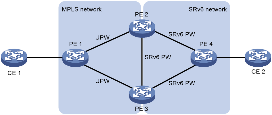
Interworking between EVPN VPWS over SRv6 and EVPN VPWS
Intra-AS EVPN VPWS over SRv6 interworking
Intra-AS EVPN VPWS over SRv6 Interworking refers to the use of different forwarding methods (SRv6 or MPLS) between PEs within the same AS, where user layer 2 data is forwarded across SRv6 and MPLS networks.
Figure 35 Intra-AS EVPN VPWS over SRv6 interworking
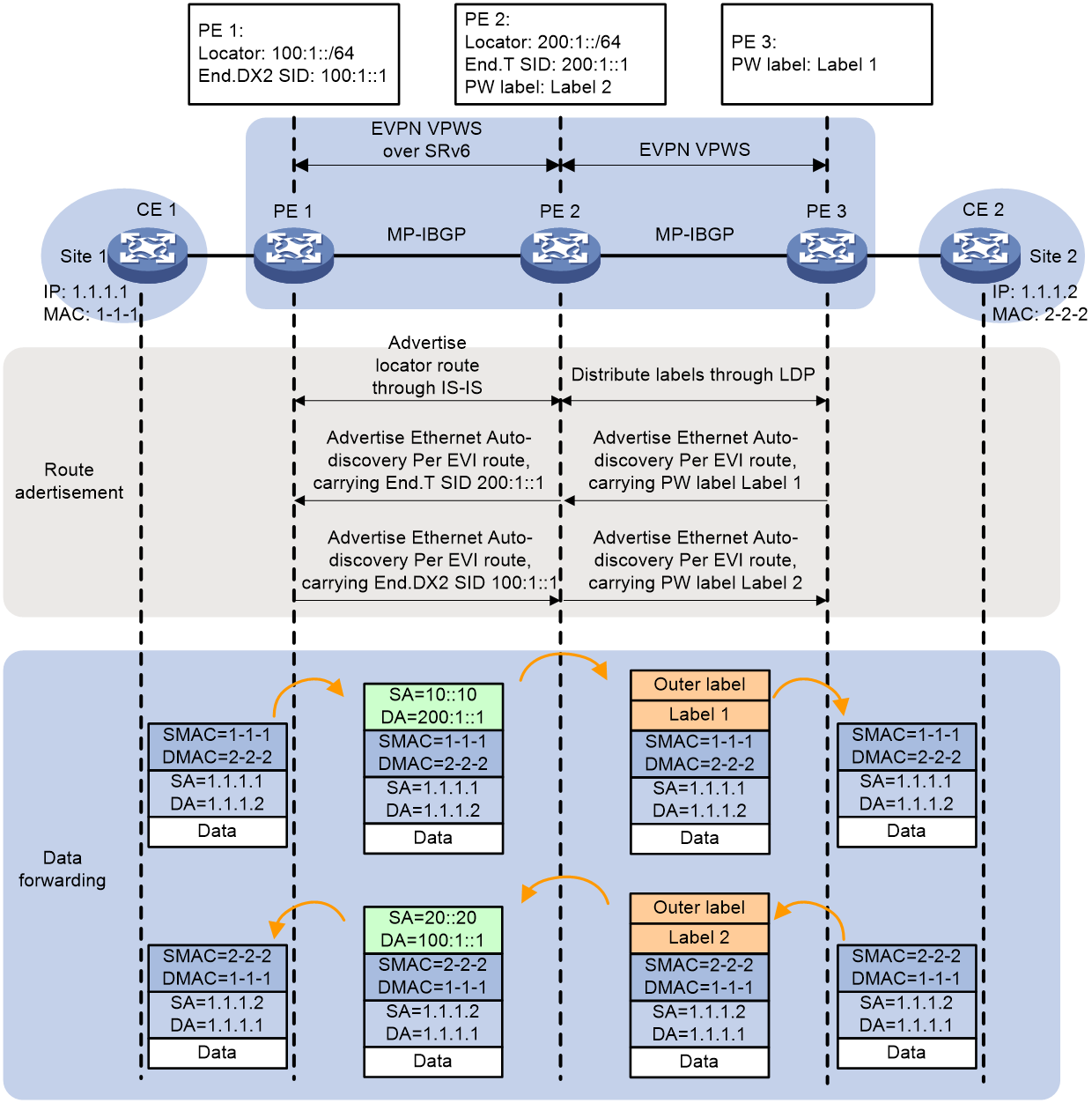
As shown in Figure 35, in the network of EVPN VPWS over SRv6 Interworking within an AS, the process of route advertisement is as follows:
1. The process of PE 3 advertising a route to PE 1 is as follows:
a. PE 3 advertises an Ethernet Auto-discovery Per EVI route to PE 2 through MP-IBGP, carrying the Local service ID and the PW label, Label 1, assigned to this Local service ID. Label 1 serves as the ingress label of the EVPN PW.
b. Upon receiving the Ethernet Auto-discovery Per EVI route, PE 2 will only accept the route if the Export target attributes in the route coincide with the Import target attributes configured locally in PE 2.
c. PE 2 advertises the Ethernet Auto-discovery Per EVI route to PE 1 through MP-IBGP, changing the next-hop address of the route to its own address. It allocates End.T SID 200:1::1 to the route, and associates it and PW tag Label 1. In the advertised route, End.T SID is used as End.DX2 SID.
d. Upon receiving a route, PE 1 checks if the 'Export target' attribute in the route matches its locally configured 'Import target' attribute. If they match, PE 1 then compares the received Local service ID with the locally configured Remote service ID. If these are the same, an SRv6 PW is established, with the End.T SID 200:1::1 advertised by PE 2 being the outgoing SID for this SRv6 PW.
2. The process of PE 1 advertising a route to PE 3 is as follows:
a. PE 1 advertises Ethernet Auto-discovery Per EVI route to PE 2 through MP-IBGP, carrying the Local service ID and the allocated End.DX2 SID 100:1::1 for that Local service ID. This End.DX2 SID serves as the ingress SID for the SRv6 PW.
b. After receiving the Ethernet Auto-discovery Per EVI route, PE 2 checks if the Export target attributes in the route match with the Import target attributes configured locally on PE 2. If they match, PE 2 receives the route.
c. PE 2 advertises the Ethernet Auto-discovery Per EVI route to PE 1 through MP-IBGP, changes the next-hop address of the route to its own address, allocates PW Label 2 for the route, and associates End.DX2 SID 100:1::1 and PW Label 2.
d. After PE 3 receives a route, if the Export target attribute in the route matches the Import target attribute locally configured in PE 1, PE 3 will compare the received Local service ID with the locally configured Remote service ID. If they are identical, the PW label Label 2 advertised by PE 2 will be used as the outgoing label for EVPN PW.
Upon completion of the route advertisement, PE 1 will have the ingress and egress SID of SRv6 PW, PE 3 will have the ingress and egress PW labels of EVPN PW, and PE 2 will have the mappings of PW labels and SRv6 SID. User layer 2 packet can be forwarded between the MPLS network and SRv6 network, according to the aforementioned information.
The process of forwarding a packet from CE 1 to CE 2 is as follows:
1. After receiving the packet transmitted by CE 1, PE 1 searches for the SRv6 PW associated with AC, and finds the corresponding End.DX2 SID 200:1::1 (i.e., the End.T SID advertised by PE 2). PE 1 encapsulates the packet with an IPv6 header, then transmits it to PE 2 via SRv6 BE or SRv6 TE methods.
2. Upon receiving the packet, PE 2 uses the correlation between End.T SID 200:1::1 and PW Label 1, and performs decapsulation to remove the IPv6 header. It then encapsulates the packet with PW Label 1 and the public network label between PE 2 and PE 3, forwarding the packet to PE 3.
3. Upon receiving the packet, PE 3 strips off the public network and PW labels. It then looks for the AC associated with the PW label and passes the packet to CE 2 through this AC.
The process of packet forwarding from CE 2 to CE 1 is as follows:
1. After receiving the packet sent by CE 2, PE 3 looks for the EVPN PW associated with AC and finds the corresponding PW tag Label 2. PE 3 encapsulates the packet with PW tag Label 2 and the public network tag between PE 3 and PE 2, and then forwards the packet to PE 2.
2. After receiving the packet, PE 2, based on the association between End.DX2 SID 100:1::1 and PW tag Label 2, strips off the MPLS label, encapsulates the packet with End.DX2 SID 100:1::1, and transmits the packet to PE 1 via SRv6 BE or SRv6 TE method.
3. Upon receiving the packet, PE 1 performs decapsulation to remove the IPv6 packet header. It then uses the End.DX2 SID 100:1::1 information to find the AC associated with PW, and forwards the packet to CE 1 through this AC.
Inter-AS EVPN VPWS over SRv6 Option A interworking
As shown in Figure 36, in the EVPN VPWS over SRv6 Option A Interworking network setup, an SRv6 network is deployed in AS 1, and an MPLS network is deployed in AS 2. The site network needs to communicate across AS 1 and AS 2. Two ASBR devices are directly connected. ASBR also serves as PE, treating the other as its own CE device, and associates AC and PW on ASBR.
Figure 36 EVPN VPWS over SRv6 Option A interworking network diagram
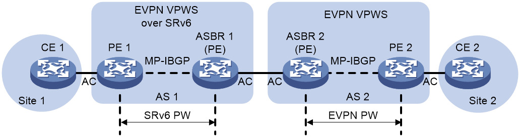
The process of route advertisement and packet forwarding for EVPN VPWS over SRv6 Option A Interworking is illustrated in Figure 37.
Figure 37 Implementation mechanism of EVPN VPWS over SRv6 Option A interworking
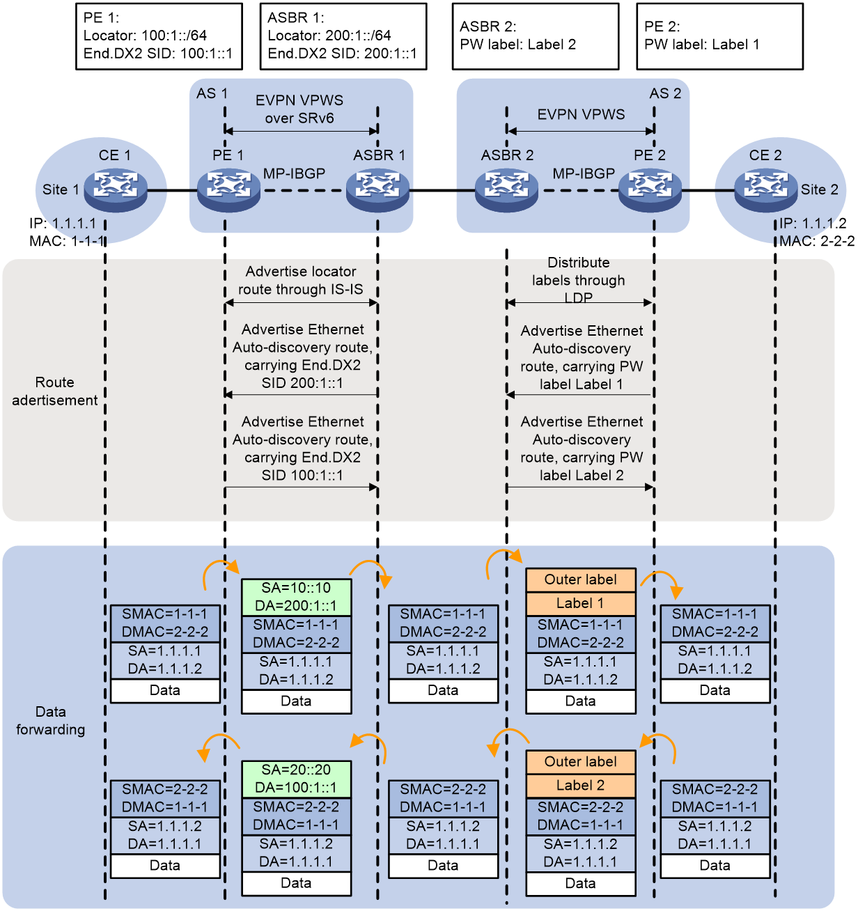
Within the AS deploying the SRv6 network, it's necessary for Provider Edge and Autonomous System Border Router to advertise the route of the network segment Locator that belongs to End.DX2 SID to all devices within that AS through IGP protocol. For instance, PE 1 advertises the route of the network segment Locator, 100:1::/64, that belongs to End.DX2 SID to other Provider and ASBR devices within the AS using the IGP protocol (IS-IS route, for example).
As shown in Figure 37, an SRv6 PW needs to be established between PE 1 and ASBR 1, and an EVPN PW between PE 2 and ASBR 2. In the network setup of EVPN VPWS over SRv6 Option A Interworking, the establishment process of SRv6 PW and EVPN PW is the same as in EVPN VPWS over SRv6 and EVPN VPWS interworking, which is not repeated here.
Once the Pseudowire (PW) is established, the process of forwarding packets from Customer Edge 1 (CE 1) to Customer Edge 2 (CE 2) is as follows:
1. Upon receiving the packet transmitted by CE 1, PE 1 looks up the SRv6 PW associated with AC, and locates the corresponding End.DX2 SID 200:1::1. PE 1 encapsulates the packet with an IPv6 header, and sends the packet to ASBR 1 either via SRv6 BE or SRv6 TE.
2. Upon receiving a packet, ASBR 1 performs decapsulation to remove the IPv6 packet header, then looks up the AC associated with PW based on the End.DX2 SID 200:1::1 and forwards the packet to its CE (i.e., ASBR 2) via this AC.
3. After receiving the packet transmitted by ASBR 1, ASBR 2 searches for the EVPN PW associated with AC and finds the corresponding PW tag, Label 1. ASBR 2 encapsulates the packet with the PW tag, Label 1, and the public network tag between ASBR 2 and PE 2, and then forwards the packet to PE 2.
4. Upon receiving the packet, PE 2 strips the public network tag and PW tag, then finds the AC associated with the PW tag. Subsequently, the packet is passed to CE 2 through this AC.
After establishing the PW, the process of CE2 accessing and forwarding packets to CE1 is as follows:
1. After PE 2 receives the packet sent from CE 2 via AC, it looks up the EVPN PW associated with AC and finds the corresponding PW tag Label 2. PE 2 encapsulates the packet with PW tag Label 2 and the public network tag between PE 2 and ASBR 2, then forwards the packet to ASBR 2.
2. After receiving the packet, ASBR 2 strips off both the public network tags and PW tags. Then it locates the AC associated with the PW tag and forwards the packet to its CE (i.e., ASBR 1) through this AC.
3. After receiving the packet transmitted by ASBR 2, ASBR 1 looks up the SRv6 PW associated with AC, and finds the corresponding End.DX2 SID 100:1::1. ASBR 1 encapsulates the packet with an IPv6 header, and transmits the packet to PE 1 either through SRv6 BE or SRv6 TE.
4. After PE 1 receives the packet, it performs decapsulation by removing the IPv6 packet header. Then, it locates the AC associated with PW using the End.DX2 SID 100:1::1, and forwards the packet to CE 1 through this AC.
Inter-AS EVPN VPWS over SRv6 Option B interworking
As shown in Figure 38, in the deployment of EVPN VPWS over SRv6 Option B Interworking network, SRv6 network is deployed in AS 1, while MPLS network is deployed in AS 2. The site network needs to pass between AS 1 and AS 2 for communication. The two ASBR devices are directly connected. The EVPN routes received from their respective AS's PE are switched between the ASBRs through MP-EBGP.
Figure 38 Network diagram for EVPN VPWS over SRv6 Option B Interworking
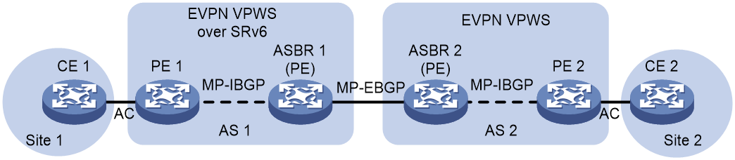
Figure 39 Mechanism for implementing EVPN VPWS over SRv6 Option B Interworking
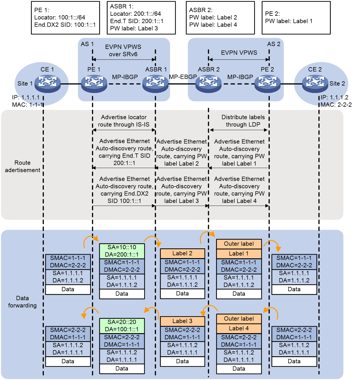
In the AS where the SRv6 network is deployed, it is necessary for PE and ASBR devices to pass routes of the network segments belonging to End.DX2 SID and End.T SID to all devices within the AS through the IGP protocol. For instance, PE 1 passes the route of the network segment of the End.DX2 SID 100:1::/64 to devices within the AS such as P and ASBR using the IGP protocol (taking IS-IS route as an example).
As shown in Figure 39, in the network setup of EVPN VPWS over SRv6 Option B Interworking, both PE and ASBR need to advertise PW labels or SRv6 SID via Ethernet Auto-discovery Per EVI route. The route advertisement process is as follows:
1. The process of PE 2 advertising a route to PE 1 is as follows:
a. PE 2 advertises Ethernet Auto-discovery Per EVI route to ASBR 2 via MP-IBGP, which carries the Local service ID and the PW label Label 1 allocated to that Local service ID. Label 1 is used as the incoming label for EVPN PW.
b. Once ASBR 2 receives the Ethernet Auto-discovery Per EVI route, if the Export target attributes in the route are the same as the Import target attributes configured locally, ASBR 2 will receive this route.
c. ASBR 2 advertises the route to ASBR 1 through MP-EBGP. When ASBR 2 advertises the route, it updates the next hop of the route to its local host address, assigns a new MPLS label, Label 2 to the route, and establishes a correlation between MPLS Label 2 and MPLS Label 1.
d. After the ASBR 1 receives a route, if the Export target attribute in the route matches the Import target attribute configured locally, then ASBR 1 receives this route.
e. ASBR 1 updates the next hop of the route to the local host address, allocates End.T SID 200:1::1 to the route, and establishes a correlation between End.T SID and MPLS Label 2. ASBR 1 passes the route to PE 1 via MP-IBGP. In this route, End.T SID is used as End.DX2 SID.
f. Once PE 1 receives a route, if the Export target attribute in the route matches the Import target attribute configured locally on PE 1, PE 1 will compare the received Local service ID with the locally configured Remote service ID. If the two are the same, an SRv6 PW is established, with the End.T SID 200:1::1 advertised by ASBR 1 serving as the outgoing SID for the SRv6 PW.
2. The process is PE 1 advertising the route to PE 2.
a. PE 1 advertising Ethernet Auto-discovery Per EVI route to ASBR 1 through MP-IBGP, this route carries the Local service ID and the End.DX2 SID 100:1::1 allocated for this Local service ID. This End.DX2 SID serves as the ingress SID for SRv6 PW.
b. After ASBR 1 receives the Ethernet Auto-discovery Per EVI route, if the Export target attributes in the route are the same as the locally configured Import target attributes, then ASBR 1 will receive this route.
c. ASBR 1 advertises it to ASBR 2 through MP-EBGP. When ASBR 1 advertises a route, it updates the next hop to its local host address, allocates PW tag Label 3 to the route, and establishes a correlation between PW tag Label 3 and End.DX2 SID.
d. Upon receiving the route, ASBR 2 will accept it if the Export target attribute in the route matches the Import target attribute configured locally.
e. ASBR 2 advertises it to PE 2 through MP-IBGP. When ASBR 2 advertises a route, it updates the next hop to its local host address, allocates PW tag Label 4 to the route, and establishes a connection between PW tag Label 4 and private network tag Label 3.
f. Upon receiving the route, if the Export target attribute in the route matches the Import target attribute locally configured on PE 1, PE 2 will compare the received Local service ID with the locally configured Remote service ID. If they are the same, the PW label Label 4 advertised by ASBR 2 will be used as the outgoing label for EVPN PW.
After completing the route advertisement, PE 1 will have the ingress and egress SID for SRv6 PW, while PE 2 will have the ingress and egress PW labels for EVPN PW. ASBR 1 and ASBR 2 will have the mappings between PW labels and SRv6 SIDs. User packets at Layer 2 can be forwarded between MPLS networks and SRv6 networks based on the above information.
The process for forwarding packets from CE 1 to CE 2 is as follows:
1. After PE 1 receives the packet transmitted by CE 1, it searches for the SRv6 PW associated with AC. It finds the corresponding End.DX2 SID 200:1::1 (which is the End.T SID advertised by ASBR 1). PE 1 encapsulates the packet with an IPv6 header, and sends the packet to ASBR 1 either through SRv6 BE or SRv6 TE.
2. After receiving the packet, ASBR 1 performs decapsulation to remove the IPv6 packet header, and forwards the packet according to the End.T SID by looking up the IPv6 FIB table. The outgoing label is Label 2. ASBR 1 re-encapsulates the packet with PW label Label 2, and then forwards the packet to ASBR 2. The packet between ASBR 1 and ASBR 2 carries only one layer of MPLS label.
3. ASBR 2 replaces MPLS label 2 with label 1, adds the label for the public network tunnel from ASBR 2 to PE 2, and forwards the packet to PE 2.
4. After receiving the packet, PE 2 strips off the public network label and PW label. Based on the PW label, it finds the AC associated with PW, then passes the packet to CE 2 through this AC.
The process of forwarding packets from CE 2 to CE 1 is as follows:
1. After PE 2 receives a packet transmitted by CE 2 from AC, it looks for the EVPN PW associated with AC and finds the corresponding PW label, Label 4. PE 2 encapsulates the packet with PW label, Label 4 and the public network label between PE 2 and ASBR 2, then forwards the packet to ASBR 2.
2. After receiving the packet, ASBR 2 strips off the public network tag, replaces the private network tag Label 4 with Label 3, and transmits the packet to ASBR 1. The packets between ASBR 1 and ASBR 2 only carry one layer of private network tags.
3. Upon receiving the packet, ASBR 1 replaces the private network label Label 3 with End.DX2 SID 100:1::1, and then transmits (Tx) the packet to PE 1 via SRv6 BE or SRv6 TE method.
4. Upon receiving the packet, PE 1 decapsulates it by removing the IPv6 packet header, then looks up the AC associated with PW through the End.DX2 SID 100:1::1, and passes the packet to CE 1 via this AC.
Interworking between EVPN VPLS over SRv6 and EVPN VPLS
In EVPN VPLS over SRv6 Interworking network configuration, the pass through process of BUM traffic and known unicast traffic between SRv6 and MPLS networks is similar to that of different type SID's SRv6 and MPLS networks. The following explanation is solely based on unicast traffic and End.DT2U SID as an example.
Intra-AS EVPN VPLS over SRv6 interworking
EVPN VPLS over SRv6 Interworking within the AS refers to different forwarding methods (SRv6 or MPLS) used between different PEs within the same AS. User layer 2 data is forwarded across SRv6 and MPLS networks.
Figure 40 Implementation mechanism of intra-AS EVPN VPLS over SRv6 interworking
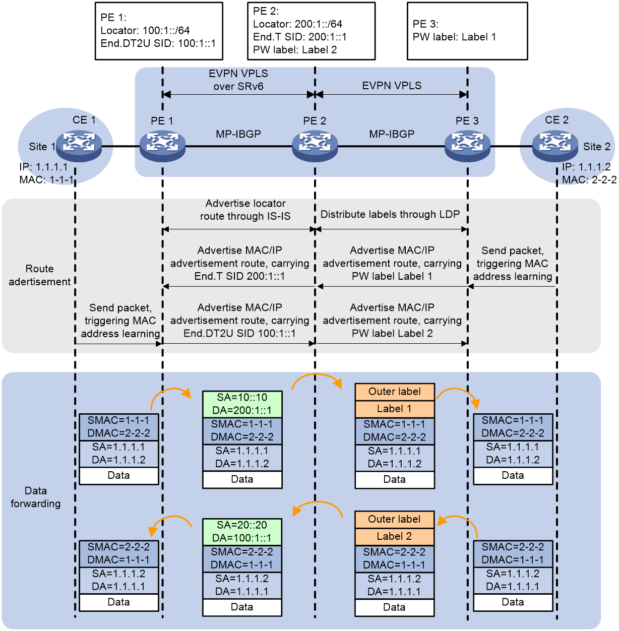
As shown in Figure 40, in the intra-AS EVPN VPLS over SRv6 Interworking network setup, the route advertisement process is as follows:
1. The process of PE 3 advertising the route to PE 1 is as follows:
a. After PE 3 receives the packet transmitted by CE 2, it learns the MAC address of CE 2 into the MAC address table of VSI instance A.
b. PE 3 advertises the MAC/IP route to PE 2 via MP-iBGP, advertising the MAC address of CE 2. This route includes the PW label, Label 1, which PE 3 assigns to VSI instance A. Label 1 serves as the ingress label for the EVPN PW.
c. After receiving a route, PE 2 accepts it if the Export target attributes in the route match the Import target attributes configured locally on PE 2.
d. PE 2 advertises MAC/IP route to PE 1 through MP-IBGP, changes the next-hop address of the route to its own address, allocates End.T SID 200:1::1 for the route, and establishes a relationship between End.T SID 200:1::1 and PW Label 1. In the advertised route, End.T SID is used as End.DT2U (U) SID.
e. Upon receiving a route, PE 1 establishes an SRv6 PW if the Export target attribute in the route matches the Import target attribute configured locally in PE 1. The End.T SID 200:1::1, advertised by PE 2, serves as the exit SID for this SRv6 PW.
2. The process of PE 1 advertising a route to PE 3 is as follows:
a. After PE 1 receives the packet transmitted by CE 1, it learns the MAC address of CE 1 and adds it to the MAC address table of VSI instance A.
b. PE 1 advertises the MAC/IP route to PE 2 via MP-IBGP, announcing the MAC address of CE 1. This route carries the End.DT2U SID 100:1::1 allocated to VSI instance A by PE 1. This End.DT2U SID serves as the entry SID for the SRv6 PW.
c. When PE 2 receives a route, if the Export target attributes in the route match the Import target attributes configured locally on PE 2, then PE 2 accepts the route.
d. PE 2 advertises MAC/IP route to PE 1 through MP-IBGP, changing the next-hop address of the route to its own address. It allocates the PW label Label 2 for the route, and establishes a link between End.DT2U SID 100:1::1 and PW label Label 2.
e. After PE 3 receives the route, if the Export target attribute in the route matches the Import target attribute locally configured on PE 1, then the PW label, Label 2, advertised by PE 2 will serve as the outgoing label for the EVPN PW.
Upon completion of the route advertisement, PE 1 will have outgoing and incoming SID for SRv6 PW, PE 3 will have outgoing and incoming PW labels for EVPN PW, and PE 2 will have mappings for PW labels and SRv6 SID. Using this information, user's layer-2 packets can be forwarded between the MPLS network and the SRv6 network.
The process of packet forwarding from CE 1 to CE 2 is as follows:
1. After PE 1 receives the packet sent by CE 1 through AC, it looks up the MAC address table in the associated VSI instance of AC and finds the corresponding End.DT2U SID 200:1::1 (that is, the End.T SID advertised by PE 2). PE 1 then encapsulates the packet with an IPv6 packet header, and transmits the packet to PE 2 via SRv6 BE or SRv6 TE method.
2. Upon receiving the packet, PE 2 decapsulates it by removing the IPv6 header, based on the association between End.T SID 200: 1:: 1 and PW label Label 1. Then, it encapsulates the packet with PW label Label 1 and the public network label between PE 2 and PE 3, and forwards the packet to PE 3.
3. After PE 3 receives the packet, it strips the public network and PW tags, and uses the PW tag to locate the associated VSI instance. It then looks up the MAC address table within the VSI instance and forwards the packet to CE 2.
The process of forwarding a packet from CE 2 to CE 1 is as follows:
1. Upon receiving the packet transmitted by CE 2, PE 3 searches for the MAC address table within the VSI instance associated with AC and finds the corresponding PW label, Label 2. PE 3 encapsulates the packet with PW Label 2 and the public network label between PE 3 and PE 2, and then forwards the packet to PE 2.
2. Upon receiving the packet, PE 2, based on the relationship between End.DT2U SID 100:1::1 and PW label Label 2, peels off the MPLS label, encapsulates the packet with End.DT2U SID 100:1::1, and then transmits the packet to PE 1 via SRv6 BE or SRv6 TE.
3. After PE 1 receives the data packet, it performs decapsulation to discard the IPv6 packet header, looks up the associated VSI instance based on the End.DT2U SID 100:1::1, and searches for the MAC address table within the VSI instance. It then forwards the data packet to CE 1.
Inter-AS EVPN VPLS over SRv6 Option A interworking
As shown in Figure 41, in the network deployment of EVPN VPLS over SRv6 Option A Interworking, an SRv6 network is deployed in AS 1, and an MPLS network is deployed in AS 2. The site network needs to communicate across AS 1 and AS 2. Two ASBR devices are directly connected. With the ASBR acting as PE, it treats the other device as its own CE device, and associates AC and PW on the ASBR.
Figure 41 Network diagram of EVPN VPLS over SRv6 Option A interworking
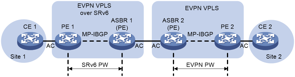
The advertisement and forwarding process of EVPN VPLS over SRv6 Option A Interworking route is shown in Figure 42.
Figure 42 Implementation mechanism for EVPN VPLS over SRv6 Option A interworking
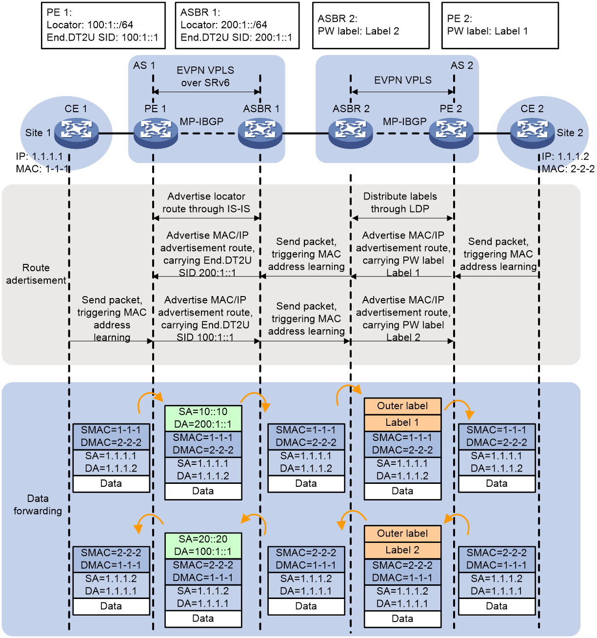
Within the AS deploying the SRv6 network, it's required for the End.DT2U SID's parent Locator route to be distributed to all devices within the AS through the IGP protocol between the PE and ASBR. For instance, PE1, via the IGP protocol (taking the IS-IS route as an example) advertises the End.DT2U SID's parent Locator route 100:1::/64 to the P and ASBR devices within the AS.
As shown in Figure 42, an SRv6 PW needs to be established between PE 1 and ASBR 1, and an EVPN PW needs to be established between PE 2 and ASBR 2. In the EVPN VPLS over SRv6 Option A Interworking network configuration, the establishment process of SRv6 PW and EVPN PW is the same as in the EVPN VPLS over SRv6 and EVPN VPLS networks, which will not be elaborated further here.
After the PW is set up, the process of packet transfer from CE 1 to CE 2 is as follows:
1. After receiving the packet transmitted by CE 1, PE 1 searches for the MAC address table within the VSI instance associated with AC, and finds the corresponding End.DT2U SID 200:1::1. PE 1 encapsulates the packet with an IPv6 header, and transmits the packet to ASBR 1 via SRv6 BE or SRv6 TE methods.
2. After ASBR 1 receives the packet, it performs decapsulation to remove the IPv6 packet header. Then, based on the End.DT2U SID 200:1::1, it finds the associated VSI instance. Within the VSI instance, it searches for the MAC address table and forwards the packet to its CE (i.e., ASBR 2).
3. After receiving the packet transmitted by ASBR 1, ASBR 2 searches for the MAC address table within the VSI instance associated with AC and finds the corresponding PW label, Label 1. ASBR 2 then encapsulates the packet with PW label Label 1 and the public network label between ASBR 2 and PE 2, and forwards the packet to PE 2.
4. After receiving the packet, PE 2 strips the public network and PW tags. Then it looks up the associated VSI instance according to the PW tag. Within the VSI instance, it searches the MAC address table and forwards the packet to CE 2.
After the PW is set up, the process for forwarding a packet from CE 2 to CE 1 is as follows:
1. After receiving the packet sent by CE 2, PE 2 looks for the MAC address table within the VSI instance associated with AC, and finds the corresponding PW tag Label 2. PE 2 wraps the packet in PW tag Label 2 and the public network tag between PE 2 and ASBR 2, then forwards the packet to ASBR 2.
2. After receiving the packet, ASBR 2 strips the public network label and PW label. Based on the PW label, it locates the associated VSI instance, and looks up the MAC address table within the VSI instance. Finally, the packet is forwarded to its CE, which is ASBR 1.
3. After receiving the packet transmitted from ASBR 2, ASBR 1 searches for the MAC address table within the associated VSI instance of AC, and finds the corresponding End.DT2U SID 100:1::1. ASBR 1 encapsulates the packet with an IPv6 header, and sends the packet to PE 1 via SRv6 BE or SRv6 TE method.
4. After receiving the packet, PE 1 performs decapsulation to remove the IPv6 packet header. It then uses the End.DT2U SID 100:1::1 to search for the associated VSI instance. Within this VSI instance, it searches the MAC address table and forwards the packet to CE 1.
Inter-AS EVPN VPLS over SRv6 Option B interworking
As shown in Figure 43, in the network segment of EVPN VPLS over SRv6 Option B Interworking, the SRv6 network is deployed in AS 1 and the MPLS network is deployed in AS 2. The site network needs to pass between AS 1 and AS 2 for interconnection. Two ASBR devices are directly connected. They exchange the EVPN routes they receive from their respective AS's PE through MP-EBGP.
Figure 43 Network diagram for EVPN VPLS over SRv6 Option B interworking
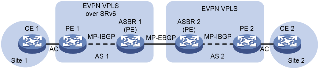
Figure 44 Mechanism for implementing EVPN VPLS over SRv6 Option B interworking
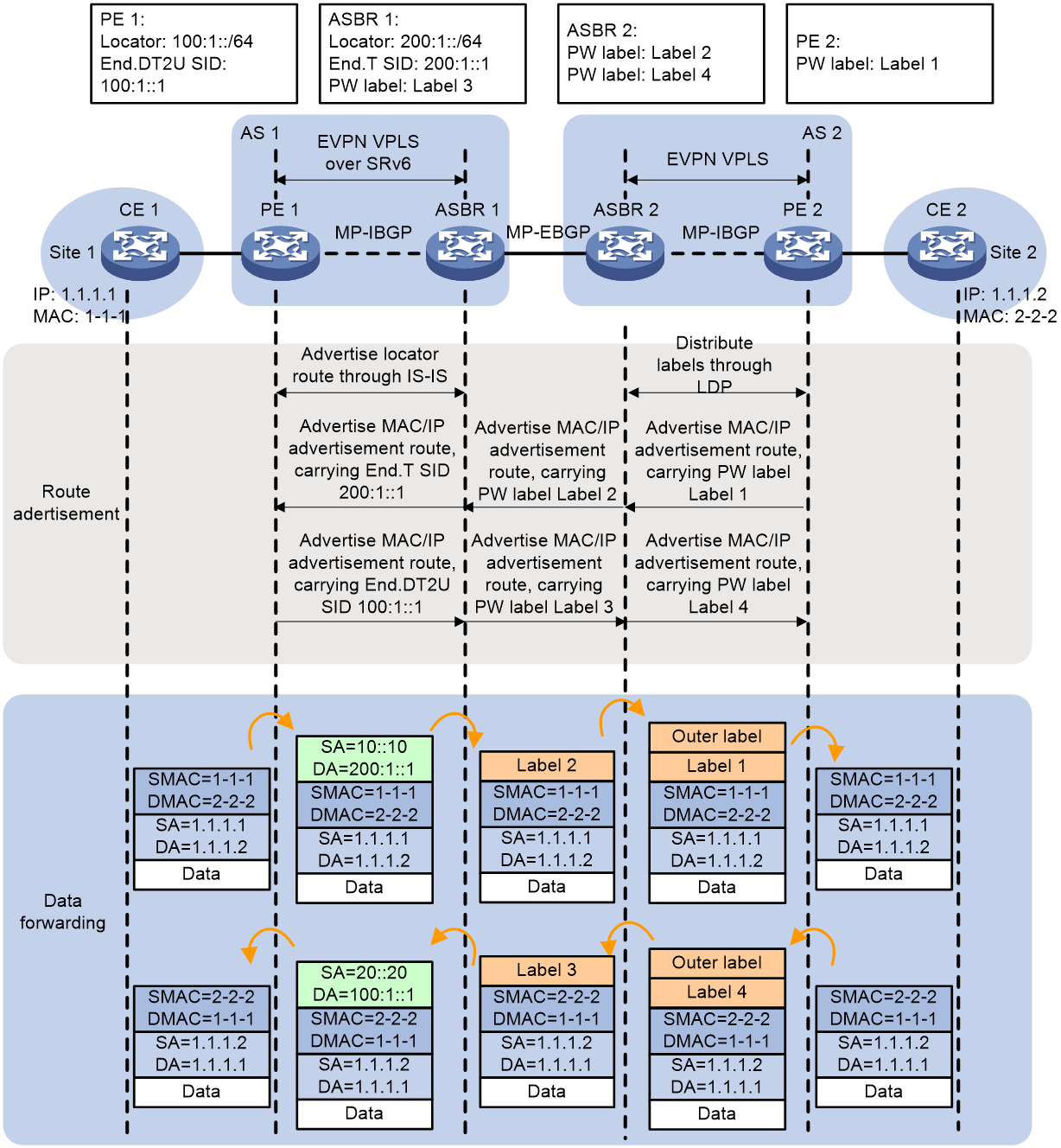
Within the AS deploying SRv6 network, the route of the network segment Locator to which End.DT2U SID and End.T SID belong needs to be advertised to all devices in the AS via the IGP protocol between PE and ASBR. For instance, PE 1 advertises the route of the network segment Locator, to which End.DT2U SID belongs, 100:1::/64 to the devices of P and ASBR in the AS via the IGP protocol (IS-IS route as an example).
As shown in Figure 44, in the EVPN VPLS over SRv6 Option B interworking network, PE and ASBR need to advertise PW labels or SRv6 SID by advertising MAC/IP route. The process of route advertisement is:
1. The process of PE 2 advertising a route to PE 1 is as follows:
a. Upon receiving the packet transmitted by CE 2, PE 2 learns the MAC address of CE 2 and adds it to the MAC address table of VSI instance A.
b. PE 2 advertises the MAC/IP route to ASBR 2 via MP-IBGP, announcing the MAC address of CE 2. This route carries the PW label Label 1, allocated by PE 2 for VSI instance A. Label 1 serves as the ingress label for EVPN PW.
c. Upon receiving a route, ASBR 2 accepts it if the Export target attributes in the route match the Import target attributes configured locally.
d. ASBR 2 passes the route to ASBR 1 through MP-EBGP. When ASBR 2 advertises the route, it updates the next hop to the local host address, allocates a new MPLS label, Label 2, to the route, and establishes a connection between MPLS Label 2 and MPLS Label 1.
e. Upon receiving a route, ASBR 1 will accept it if the Export target attributes in the route match the Import target attributes configured locally.
f. ASBR 1 advertises routes to PE 1 via MP-IBGP. When ASBR 1 advertises a route, it updates the next hop to the local host address, allocates End.T SID 200:1::1 to the route, and establishes a relation between End.T SID and MPLS label Label 2. In this route, End.T SID is used as End.DT2U SID.
g. Upon receiving a route, if the 'Export target' attribute in the route matches the 'Import target' attribute configured locally on PE 1, a SRv6 PW is established. The End.T SID 200:1::1 advertised by ASBR 1 serves as the outgoing SID for this SRv6 PW.
2. The process is for PE 1 to advertise the route to PE 2.
a. After PE 1 receives the packet transmitted by CE 1, it learns the MAC address of CE 1 into the MAC address table of VSI instance A.
b. PE 1 advertises the MAC address of CE 2 by advertising the MAC/IP route to ASBR 1 through MP-IBGP. This route carries the End.DT2U SID 100:1::1, which PE 1 allocates for the VSI instance A. The End.DT2U SID serves as the ingress SID for the SRv6 PW.
c. Upon receiving a route, ASBR 1 accepts it if the Export target attribute in the route matches the locally configured Import target attribute.
d. ASBR 1 advertises the route to ASBR 2 via MP-EBGP. When ASBR 1 advertises the route, it updates the next hop as the local host address, allocates PW tag Label 3 to the route, and establishes a connection between PW tag Label 3 and End.DT2U SID.
e. After ASBR 2 receives a route, if the Export target attributes in the route match the locally configured Import target attributes, then ASBR 2 accepts the route.
f. ASBR 2 advertises the route to PE 2 via MP-IBGP. When ASBR 2 advertises the route, it updates the next hop to the local host address, allocates the PW label Label 4 to the route, and establishes a correlation between PW Label 4 and Label 3.
g. Upon receiving the route, if the Export target attribute in the route matches the Import target attribute locally configured on PE 1, then the PW Label 4 advertised by ASBR 2 serves as the outgoing label for the EVPN PW.
Upon completion of the route advertisement, PE 1 will possess in-and-out SIDs of SRv6 PW, PE 2 will hold in-and-out PW labels of EVPN PW, and ASBR 1 and ASBR 2 will have mappings of PW labels and SRv6 SIDs. User Layer 2 packet can be forwarded between the MPLS network and the SRv6 network based on the aforementioned information.
The process of forwarding a packet from CE 1 to CE 2 is as follows:
1. After receiving the packet transmitted by CE 1, PE 1 looks up the MAC address table within the VSI instance related to AC, finding the corresponding End.DT2U SID 200:1::1 (i.e., the End.T SID advertised by ASBR 1). Then, PE 1 encapsulates the packet with an IPv6 header and sends the packet to ASBR 1 through either SRv6 BE or SRv6 TE method.
2. After receiving the packet, ASBR 1 performs decapsulation to remove the IPv6 packet header, and forwards the packet according to the End.T SID by looking up the IPv6 FIB table, with the outgoing label being Label 2. ASBR 1 re-encapsulates the packet with PW label Label 2, and forwards the packet to ASBR 2. The packets between ASBR 1 and ASBR 2 carry only one layer of MPLS label.
3. ASBR 2 replaces MPLS label Label 2 with Label 1, adds the label for the public network tunnel from ASBR 2 to PE 2, and forwards the packet to PE 2.
4. After PE 2 receives the packet, it removes the public network tag and PW tag. It then searches for the associated VSI instance based on the PW tag, looks up the MAC address table within the VSI instance, and forwards the packet to CE 2.
The process of forwarding a packet from CE 2 to CE 1 is as follows:
1. After PE 2 receives a packet transmitted from CE 2, it looks up the MAC address table within the associated VSI instance of AC and finds the corresponding PW label Label 4. PE 2 then encapsulates the packet with PW label Label 4 and the public network label between PE 2 and ASBR 2, forwarding the packet to ASBR 2.
2. Upon receiving the packet, ASBR 2 strips off the public network tag and replaces the private network tag Label 4 with Label 3, then transmits the packet to ASBR 1. The packets between ASBR 1 and ASBR 2 only carry one layer of private network tags.
3. After receiving the packet, ASBR 1 replaces the private network label Label 3 with End.DT2U SID 100:1::1, and transmits (Tx) the packet to PE 1 via SRv6 BE or SRv6 TE methods.
4. After PE 1 receives the packet, it performs decapsulation to remove the IPv6 packet header. PE 1 then looks for the associated VSI instance based on the End.DT2U SID 100:1::1 and searches for the MAC address table within the VSI instance. Finally, PE 1 forwards the packet to CE 1.
SRv6 VPN reliability mechanisms
Mirror FRR protection of SRv6
In the networking of IP L3VPN over SRv6/EVPN L3VPN over SRv6/EVPN VPLS over SRv6/EVPN VPWS over SRv6, the public network tunnel is an SRv6 tunnel. If a fault occurs at the tail-end node of the SRv6 tunnel, this can lead to a failure in packet forwarding. Therefore, it is necessary to provide protection for the tail-end node of the SRv6 tunnel.
SRv6 Mirror FRR is only applicable to dual homing network scenarios, requiring the tail-end node and the node protecting the tail-end node to have the same forwarding entry.
As shown in Figure 45, either SRv6 TE Policy or SRv6 BE is deployed between PE 1 and PE 3. PE 3 is the tail-end node of the SRv6 tunnel. To enhance reliability, PE 4 provides protection for PE 3.
Figure 45 SRv6 Mirror FRR Protection network diagram
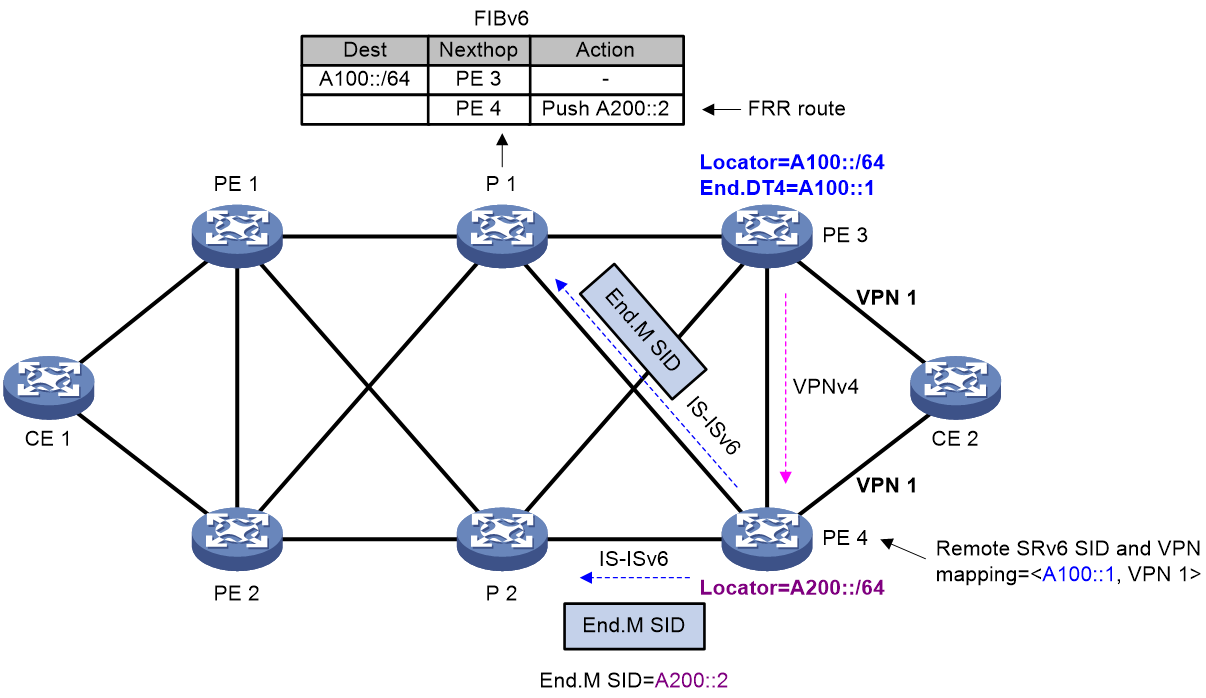
End.M SID
In the scenario of SRv6 Mirror FRR protection, the End.M SID is used to protect the designated Locator, that is, the SRv6 SID within the assigned Locator section. If the SRv6 SID advertised by the remote device falls within the range of the designated Locator section, the End.M SID is used to protect this SRv6 SID (referred to as the remote SRv6 SID). In different networking environments, the forwarding action corresponding to the End.M SID varies.
1. IP L3VPN over SRv6/EVPN L3VPN over SRv6 Mirror FRR protection scenario: The forwarding action corresponding to the End.M SID is to strip off the outer IPv6 packet header and obtain the inner packet information. The destination IPv6 address of the inner packet serves as the remote SRv6 SID, and the mapping table between the remote SRv6 SID and VPN-instance is queried to find the corresponding VPN-instance. The packet is then forwarded after looking up in the routing table of that VPN-instance.
2. EVPN VPWS over SRv6 end node protection scenario: The forwarding action corresponding to the End.M SID is to strip off the outer IPv6 packet header to obtain the inner packet information. The destination IPv6 address of the inner packet serves as the remote SRv6 SID. Query the mapping table of the remote SRv6 SID and the cross-connections to find the corresponding cross-connection. The packet is forwarded through the AC associated with this cross-connection.
3. EVPN VPLS over SRv6 end node protection scenario: The forwarding action corresponding to the End.M SID is to strip off the outer IPv6 packet header and acquire the inner packet information. The destination IPv6 address of the inner packet is used as the remote SRv6 SID, a query is made for the mapping table of the remote SRv6 SID and VSI, the corresponding VSI is found, and the MAC address table is forwarded within the VSI.
Remote SRv6 SID
As shown in Figure 45, after PE 4 receives BGP route from PE 3, if the SRv6 SID within the BGP route falls within the range of End.M SID protection on PE 4, then the SRv6 SID is the remote SRv6 SID. Simultaneously, a mapping table of the remote SRv6 SID to the VPN-instance/cross-connection/VSI is created on PE 4.
When PE 3 faults, the neighbor connection between PE 4 and PE 3 is disrupted, causing the BGP route received by PE 4 from PE 3 to be deleted. This, in turn, results in the deletion of the mapping table of the remote SRv6 SID, VPN instance, cross-connections and VSI, causing packet loss. To avoid this situation, one solution is to delay the deletion of the mapping table on PE 4. Before PE 1 detects the fault of PE 3 and calculates a new forwarding path, this ensures that the traffic is forwarded through PE 4, thus avoiding packet loss.
Route advertisement
The advertisement process of routes in IP L3VPN/EVPN L3VPN/EVPN VPWS/EVPN VPLS over SRv6 Mirror FRR protection scenario is similar. Here, we take the IP L3VPN over SRv6 Mirror FRR protection scenario as an example to introduce it.
As shown in Figure 45, the process of generating the FRR path on P1 is as follows:
1. PE 4 advertises the End.M SID and the protected Locator to its neighbor P 1 via IS-ISv6 routing, while simultaneously generating an End.M SID Local SID table on PE 4.
2. Upon receiving the route carrying End.M SID, it generates FRR route information to reach the specified Locator, with the action to push in End.M SID. The forwarding path corresponding to this FRR route is the Mirror FRR path.
As shown in Figure 45, the process of creating a mapping table for the remote SRv6 SID and VPN-instance on PE 4 is as follows:
1. After receiving the private network route advertised by CE 2, PE 3 encapsulates it into a VPNv4 route and transmits it to PE 4. The route carries SRv6 SID, RT, and RD information.
2. After receiving the VPNv4 route from PE 3, PE 4 obtains the SRv6 SID corresponding to that VPN instance. PE 4 then performs the longest match with the Locator section protected by this SRv6 SID and End.M SID. If a match is found, this SRv6 SID is designated as the remote SRv6 SID, and a mapping table of the remote SRv6 SID to the VPN instance is generated on PE 4.
Packet forwarding
The packet forwarding process in scenarios like the tail node protection for IP L3VPN/EVPN L3VPN/EVPN VPWS/EVPN VPLS over SRv6 is similar. The following example illustrates the IP L3VPN over SRv6 Mirror FRR protection scenario.
Figure 46 SRv6 Mirror FRR protection forwarding
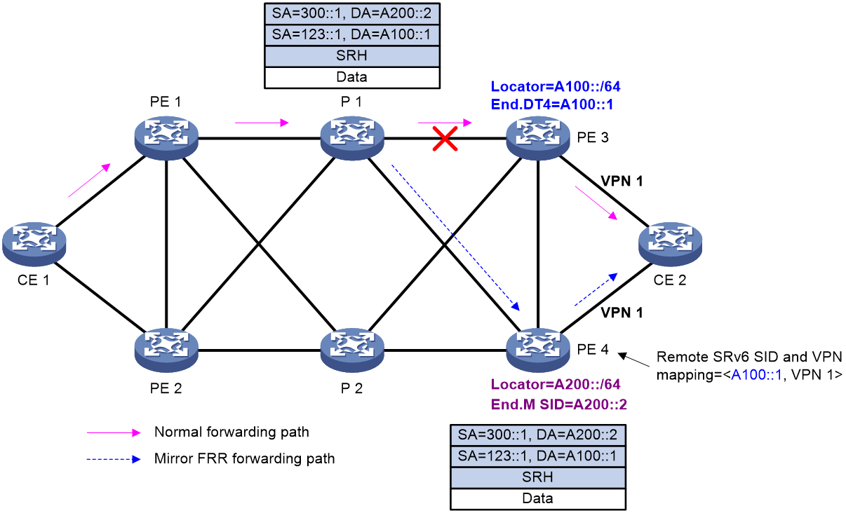
As shown in Figure 46, under normal circumstances, the traffic is forwarded via the path CE 1-PE 1-P 1-PE 3-CE 2. When the tail node PE 3 encounters a fault, the process for packet forwarding is as follows:
1. Node P1 detects that the next hop PE3 is unreachable and switches to the FRR path. P1 encapsulates the packet with an IPv6 header, wherein the destination address is End.M SID, and then forwards it to PE4.
2. After receiving the packet, PE 4 queries the Local SID table and matches an End.M SID. PE 4 then executes the forwarding action corresponding to the End.M SID, which is to decapsulate the packet and retrieve the information from the inner packet. The destination IPv6 address of the inner packet serves as the remote SRv6 SID. It queries the mapping table of the remote SRv6 SID and VPN-instance, finding the corresponding VPN-instance 1. Subsequently, on PE 4, it queries the routing table of VPN-instance 1 to forward the traffic to CE 2.
SBFD for SRv6 BE
About BFD and SBFD
The Bidirectional Forwarding Detection (BFD) protocol offers a general, standardized, media-independent, and protocol-independent rapid fault detection mechanism. As shown in Figure 47, the BFD detection mechanism requires two systems to negotiate and establish a BFD session, and maintain a BFD state machine. The BFD session uses a three-way handshake to negotiate, and after successful negotiation, BFD packets are transmitted at regular intervals to detect faults in the path between systems. When the network scenario requires configuring a large number of BFD sessions for detection, the time consumption for BFD negotiation and session establishment may increase, which is not conducive to the implementation of rapid detection.
Seamless Bidirectional Forwarding Detection (SBFD) involves initiator and reflector. Only the initiator establishes and maintains the state machine, while the reflector only performs a loopback on the received SBFD packets and doesn't carry out any maintenance on the state machine. Moreover, compared to BFD, SBFD simplifies the session negotiation mechanism, hence reducing the session negotiation time. For a detailed introduction on BFD and SBFD, please refer to the BFD Technology White Paper.
In scenarios with numerous VPN services, if there is a need to configure a large number of BFD or SBFD sessions for rapid fault detection, SBFD performance surpasses that of BFD.
Figure 47 BFD and SBFD State Machines
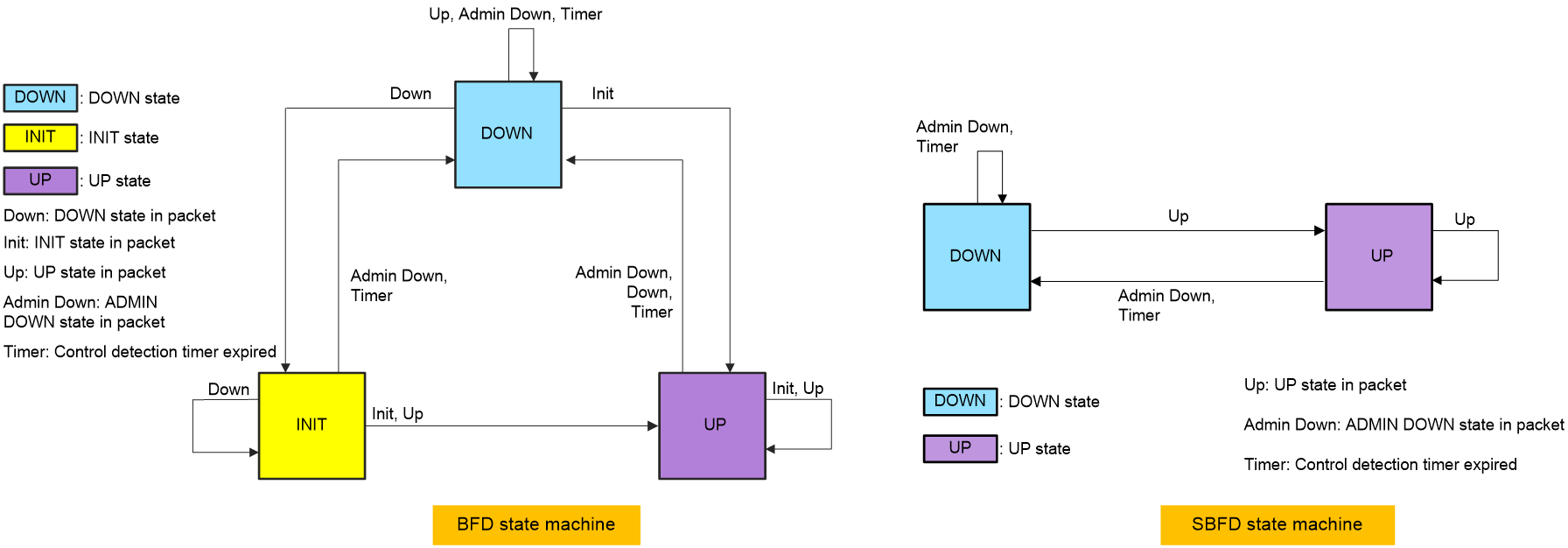
Networking scenarios for SBFD for SRv6 BE
In the scenarios of IP L3VPN over SRv6 BE, EVPN L3VPN over SRv6 BE, or IP public network over SRv6 BE, the network setup of dual-homing CE can be configured with the SBFD for SRv6 BE function to quickly trigger the VPN FRR switchover.
As shown in Figure 48, in the IPv4 L3VPN over SRv6 BE network, when the remote CE 2 has dual homing access to PE 2 and PE 3 devices, after enabling the VPN FRR function on the local PE 1 device, two paths, standby and main, will form on local PE 1. If a fault occurs on the main path, in order to enable the traffic to swiftly switchover to the backup path for forwarding, the detectability of the main path's remote PE 2 advertised SRv6 Locator A (200:1::) can be checked quickly by deploying the SBFD for SRv6 Locator function on the local PE 1 device. This, consequently, can trigger a swift VPN FRR switchover.
Figure 48 SBFD for SRv6 BE network diagram
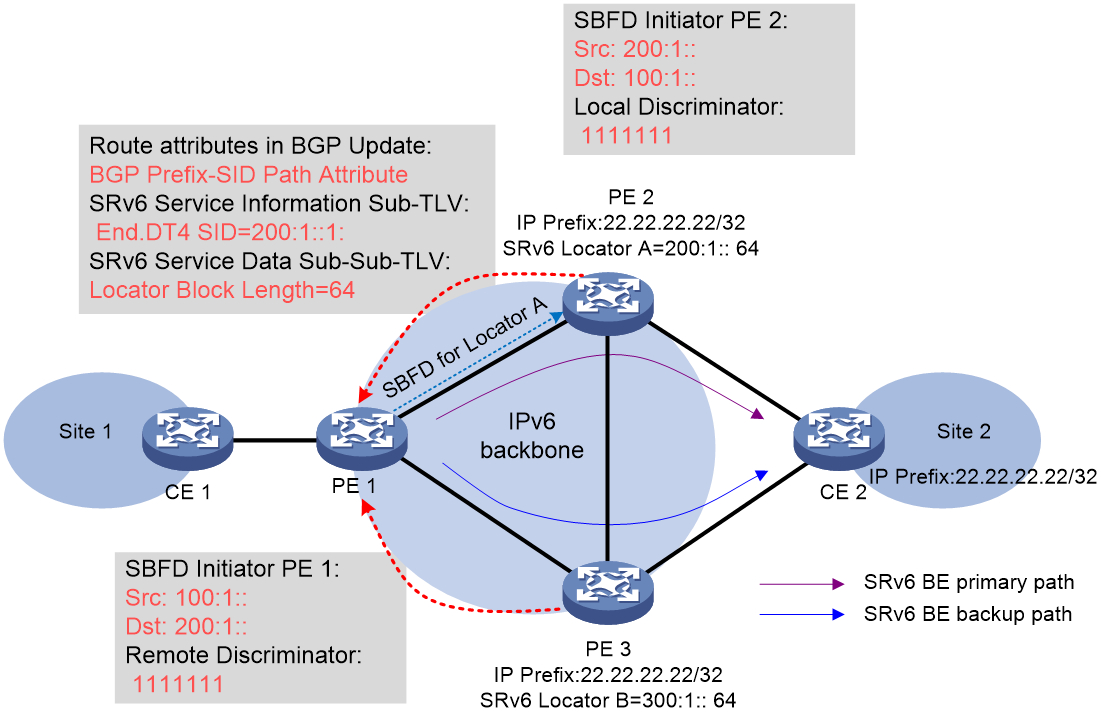
Operating mechanism of SBFD for SRv6 BE
As shown in Figure 48, the process of SBFD detecting the connectivity of the SRv6 Locator is as follows:
1. PE 2 establishes an MP-BGP neighbor relationship with PE 1 and automatically allocates an End.DT4 SID (i.e. 200:1::1:) for the private network route 22.22.22.22/32 from the local SRv6 Locator A with a prefix length of 64. The End.DT4 SID is carried in the BGP Prefix-SID route attributes of the BGP VPNv4 route Update packet, which also includes the Locator Block Length, indicating the Locator prefix length and other information. Upon receiving the BGP route, PE 1 can calculate the SRv6 Locator for the End.DT4 SID as SRv6 Locator A.
2. PE 1, as the Initiator, transmits the SBFD packet and uses SRv6 Locator A of PE 2 as the destination address to verify its reachability. The SBFD packet also carries key information such as the configured source IP address and remote identifier (ID).
3. Upon receiving the SBFD packet as a Reflector, the PE 2 device checks if the remote identifier (ID) carried in the packet matches with the local configuration's identifier (ID). If they match, the Reflector transmits (Tx) the SBFD response packet to the Initiator through the IPv6 routing. If they do not match, the Reflector will discard the received SBFD packet.
4. If the Initiator receives the SBFD response packet before the detection timeout, it considers the connectivity of the SRv6 Locator A network segment to be normal. Otherwise, the Initiator considers the SRv6 Locator A network segment unreachable and quickly switches to the backup path of the VPN private network address.
References
· draft-ietf-idr-bgpls-srv6-ext-05
· draft-ietf-bess-srv6-services-02
· draft-ietf-spring-srv6-network-programming-16
· draft-ietf-rtgwg-segment-routing-ti-lfa-05
· draft-ietf-spring-segment-routing-policy-09
· draft-ietf-6man-spring-srv6-oam-05
· draft-ietf-lsr-isis-srv6-extensions-08
· draft-ietf-rtgwg-srv6-egress-protection-11
· RFC 8667: IS-IS Extensions for Segment Routing
· RFC 8754: IPv6 Segment Routing Header (SRH)
