- Released At: 18-04-2024
- Page Views:
- Downloads:
- Table of Contents
- Related Documents
-
SRv6 Technology White Paper
Copyright © 2024 New H3C Technologies Co., Ltd. All rights reserved.
No part of this manual may be reproduced or transmitted in any form or by any means without prior written consent of New H3C Technologies Co., Ltd.
Except for the trademarks of New H3C Technologies Co., Ltd., any trademarks that may be mentioned in this document are the property of their respective owners.
This guide describes only the most common information for lightning protection. Some information might not be applicable to your products.
Contents
SRv6 SID Structure Sub-Sub-TLV
BGP LS for SRv6 application scenario
BGP-LS for SRv6 route extension
About SRv6
Technical background
The development of cloud computing poses new challenges to WANs, demanding a transformation of traditional WAN infrastructure. SD-WAN, as the core technology for WAN reconstruction, accelerates network delivery, optimizes application experience, increases bandwidth utilization, and simplifies network operations through automatic deployment, centralized control, intelligent scheduling, and visualization, thus fulfilling the WAN requirements of cloud computing.
Intelligent scheduling is a key capability of the next-generation WAN, crucial for ensuring application quality and optimizing bandwidth resources. Existing traffic engineering technologies such as MPLS and RSVP-TE can meet differentiated bandwidth requirements for applications, but they face issues such as protocol variety, complex deployment, difficult management, and poor scalability. They cannot fulfill the dynamic deployment, flexible scheduling, rapid response, and scalability demanded by the new WAN generation. Consequently, a new protocol called Segment Routing has emerged.
Segment Routing (SR) uses a source-based path selection mechanism, where the source node pre-encapsulates the Segment Identifiers (SIDs) allocated to the nodes along the path. When a packet passes through an SR node, that node forwards the packet based on its SID. Nodes other than the source do not need to maintain path state.
SRv6 specifies the forwarding path of a packet by inserting a Segment Routing Header (SRH) in the IPv6 packet and adding the segment identifiers (SIDs) of all segments (also called SID list) to be traversed in the SRH.
SRv6 offers a flexible and efficient control method for SD-WAN networks, characterized by simple deployment and ease of expansion. It enhances traffic scheduling and path optimization, ensuring quality of critical services, equalizing traffic distribution, and increasing dedicated line utilization while reducing line costs.
Technical advantages
SRv6 features the following advantages:
· Simplified maintenance
Only the source node requires control and maintenance of path information. Other nodes in the network do not need to maintain it.
· Smart control
SRv6, designed based on the SDN architecture, bridges the gap between applications and networks, enabling application-driven networking. In SRv6, forwarding paths, forwarding behaviors, and service types are all controllable.
· Easy deployment
SRv6 is implemented based on IGP and BGP extensions, eliminating the need for MPLS labels and label distribution protocols, simplifying configuration.
In an SRv6 network, new services can be deployed without the need to upgrade a large number of network devices. For example, in data centers and WANs, new services can be deployed as long as the edge devices and specific network nodes support SRv6 and the other devices support IPv6.
· Adaptive to 5G services
With the development of 5G services, IPv4 addresses are no longer sufficient to meet the network requirements of service providers. You can deploy SRv6 in service provider networks to enable all devices to forward traffic through IPv6 addresses, addressing the requirements of 5G services.
· Easy implementation of new services such as VPN
SRv6 defines multiple types of SIDs, each with a distinct role, indicating various forwarding actions. By operating different SIDs, it facilitates services such as VPN processing.
You can define new SID types as needed in the future, offering excellent expandability.
Mechanism
IPv6 SR (SRv6) uses IPv6 addresses as SIDs to forward packets.
SRv6 packet and SRH
An outer IPv6 header and a Segment Routing Header (SRH) are added to the original Layer 3 data packet to form an SRv6 packet.
In some scenarios, the source node does not add a new IPv6 header but inserts an SRH into the original IPv6 packet's header. The format of the inserted SRH extension is consistent. This document will not detail this packet encapsulation format further.
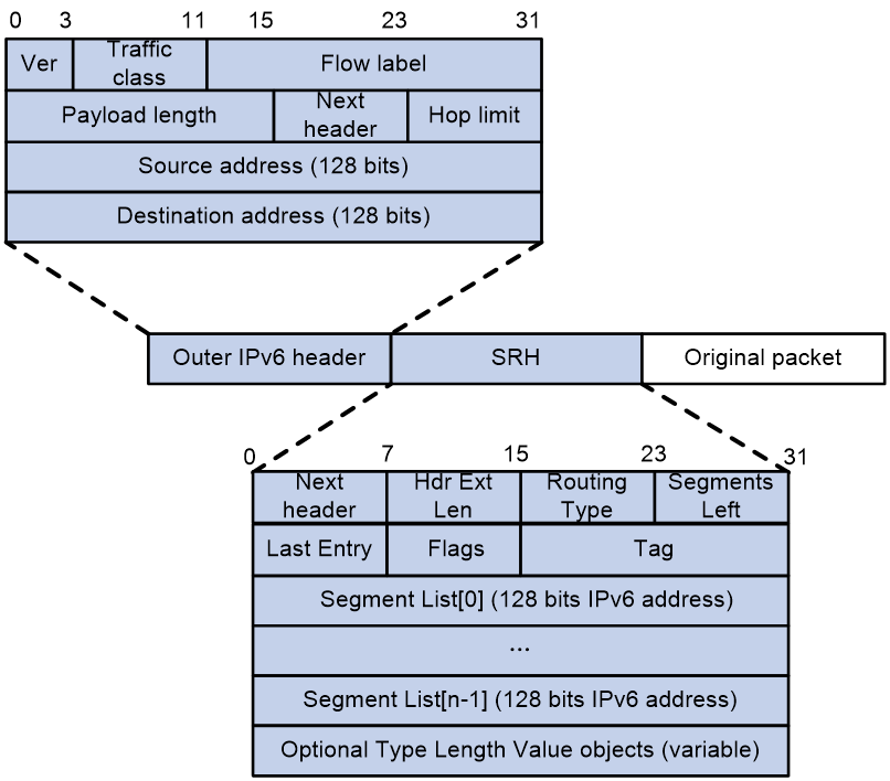
As shown in Figure 1, the value for the Next Header field is 43 in the outer IPv6 header, which indicates that the header next to the IPv6 header is a routing extension header. The value for the Routing Type field in the routing extension header is 4, which indicates that the routing extension header is an SRH. The SRH header contains the following fields:
· Next Header—8 bits, used to identify the type of the next header.
· Hdr Ext Len—8 bits, length of the SRH in units of 8 bytes, excluding the first 8 bytes.
· Routing Type—8 bits. This field is set to 4 for the SRH.
· Segments Left—Contains the index of the next segment to inspect in the Segment List. The Segments Left field is set to n-1, where n is the number of segments in the Segment List. Segments Left is decremented by 1 at each node.
· 8-bit Last Entry—Contains the index of the first SID in the path used to forward the packet.
· 8-bit Flags—Contains flags.
· 16-bit Tag—Tags a packet as part of a class or group of packets, for example, packets sharing the same set of properties.
· Segment List—Contains 128-bit IPv6 addresses representing the ordered segments. The Segment List is encoded starting from the last segment of the path. The first element of the segment list (Segment List [0]) contains the last segment of the path, the second element (Segment List [1]) contains the penultimate segment of the path and so on. The number enclosed in a pair of brackets is the index of a segment.
SRH processing process
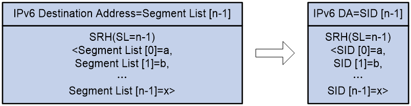
To facilitate understanding of SRv6 forwarding principles, SRv6 messages are simplified as shown in Figure 2.
· IPv6 Destination Address: The destination address for an IPv6 packet, abbreviated as IPv6 DA. In regular IPv6 packets, the IPv6 DA is fixed. In SRv6, the IPv6 DA only identifies the next node for the current packet and changes continuously.
· SRH(SL=n-1)<Segment List [0]=a, Segment List [1]=b, …, Segment List [n-1]=x>: This is the SID list for an SRv6 message. The IPv6 DA value is determined by both the SL and Segment List fields.
Figure 2 SRv6 packet simplification
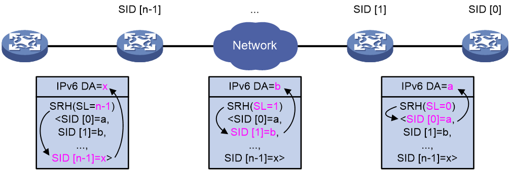
As shown in Figure 3, in SRv6, the SL field decreases by one and the IPv6 DA information changes each time the packet passes through an SRv6 node.
· If SL=n-1, the IPv6 DA is SID[n-1]=x.
· If SL=1, the IPv6 DA is SID [1]=b.
· If SL=0, the IPv6 DA is SID[0]=a.
Figure 3 SRH processing flowchart
SRv6 SID
SRv6 supports SRv6 SIDs that have specific functions.
An SRv6 SID is in the format of IPv6 address, but the IPv6 address does not belong to any interface on any device.
SID portions
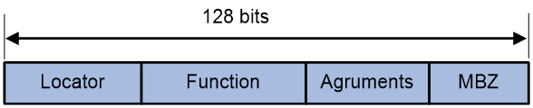
As shown in Figure 4, an SRv6 SID contains the Locator, Function, Arguments, and Must be zero (MBZ) portions.
· Locator—Identifies the network segment of the SID. The locator of an SRv6 SID must be unique in the SR domain.
· Function—Contains an opcode that identifies the network function of a SID. An SR node will execute the function in the SRv6 SID Function field of an SRv6 packet after it receives that SRv6 packet.
· Arguments—Defines flow and service parameters for SRv6 packets.
· MBZ—When the total number of bits in the Locator, Function, and Arguments portions is less 128bits, the remaining bits are padded with 0s.
· End SID—Identifies a node in the network, representing the prefix of a destination address. Upon arrival of packets at the node, if the SL is greater than 0, the node behavior is to decrease the SL by 1, extract the next SID from the SRH to update the destination address field in the IPv6 header, search for the routing table, and then forward the packet.
· End.X SID—Identifies a link in the network. The node behavior is to forward a packet from the link identified by the End.X SID to the next hop based on the Layer 3 interface bound to the SID.
· End.DT4 SID—Identifies an IPv4 VPN in the network. The function of an End.DT4 SID is decapsulating packets and searching the routing table of the corresponding IPv4 VPN instance to forward the packets. End.DT4 SIDs are applicable to IPv4 L3VPN over SRv6, EVPN IPv4 L3VPN over SRv6, and public IPv4 over SRv6 scenarios.
· End.DT6 SID—Identifies an IPv6 VPN in the network. The function of an End.DT6 SID is decapsulating packets and searching the routing table of the corresponding IPv6 VPN instance to forward the packets. End.DT6 SIDs are applicable to IPv6 L3VPN over SRv6, EVPN IPv6 L3VPN over SRv6, and public IPv6 over SRv6 scenarios.
· End.DT46 SID—Identifies an IPv4 or IPv6 VPN in the network. The function of an End.DT46 SID is decapsulating packets and searching the routing table of the corresponding IPv4 or IPv6 VPN instance to forward the packets. End.DT46 SIDs are applicable to IPv4 L3VPN over SRv6, EVPN IPv4 L3VPN over SRv6, public IPv4 over SRv6, IPv6 L3VPN over SRv6, EVPN IPv6 L3VPN over SRv6, and public IPv6 over SRv6 scenarios.
· End.DX4 SID—Identifies an IPv4 next hop in the network. The function of an End.DX4 SID is decapsulating packets and forwarding the decapsulated IPv4 packets out of the Layer 3 interface bound to the SID to a specific next hop. End.DX4 SIDs are applicable to IPv4 L3VPN over SRv6, EVPN IPv4 L3VPN over SRv6, and public IPv4 over SRv6 scenarios.
· End.DX6 SID—Identifies an IPv6 next hop in the network. The function of an End.DX6 SID is decapsulating packets and forwarding the decapsulated IPv6 packets out of the Layer 3 interface bound to the SID to a specific next hop. End.DX6 SIDs are applicable to IPv6 L3VPN over SRv6, EVPN IPv6 L3VPN over SRv6, and public IPv6 over SRv6 scenarios.
· End.DX2 SID—Identifies one end of a Layer 2 cross-connect. The function of an End.DX2 SID is decapsulating packets and forwarding the decapsulated packets to the output interface of the SID. End.DX2 SIDs are applicable to EVPN VPWS over SRv6 and EVPN VPLS over SRv6 scenarios.
· End.DX2L SID—Identifies packets that come from a bypass SRv6 PW. The packets will not be forwarded back to the bypass SRv6 PW for loop prevention. The function of an End.DX2L SID is decapsulating packets and forwarding the decapsulated packets to the output interface of the SID. End.DX2L SIDs are applicable to EVPN VPWS over SRv6 multihomed and EVPN VPWS over SRv6 multihomed sites.
· End.DT2M SID—Identifies one end of a Layer 2 cross-connect and floods traffic. The function of an End.DT2M SID is decapsulating packets and flooding the decapsulated packets in the VSI. End.DT2M SIDs are applicable to EVPN VPLS over SRv6 scenarios.
· End.DT2U SID—Identifies one end of a Layer 2 cross-connect and performs unicast forwarding. The function of an End.DT2U SID is decapsulating packets, looking up the MAC address table for the destination MAC address, and forwarding the packets to the output interface based on the MAC address entry. End.DT2U SIDs are applicable to EVPN VPLS over SRv6 scenarios.
· End.DT2UL SID—Identifies packets that come from a bypass SRv6 PW. The packets will not be forwarded back to the bypass SRv6 PW for loop prevention. The function of an End.DT2UL SID is decapsulating packets and forwarding the packets to the output interface through destination MAC address lookup. End.DT2UL SIDs are applicable to EVPN VPLS over SRv6 multihomed sites.
· End.OP SID—An OAM type SID. The function of an End.OP SID is checking the next SRv6 SID. If the next SRv6 SID is a local one, the device responds with an acknowledgment packet. If it is not a local one, it discards the packet. End.OP SID are applicable to SRv6 OAM scenarios.
· End.M SID—Protects a locator, meaning it protects the SRv6 SIDs in the locator. If a remote device advertises an SRv6 SID that falls within the range of a specified locator, the End.M SID is used to protect that SRv6 SID (the remote SRv6 SID). The function of an End.M SID is decapsulating a packet to retrieve the inner packet information. The destination IPv6 address of the inner packet acts as the remote SRv6 SID and performs the forwarding action associated with the remote SRv6 SID. End.M SIDs are used in egress node protection scenarios.
· End.T SID—Applies to the inter-AS option B solution.
· End.AS SID—Applies to the SRv6 service chain static proxy scenario. For more information about End.AS SIDs, see SRv6 SFC Technology White Paper.
· End.AM SID—Applies to the SRv6 service chain Pseudo proxy scenario. For more information about End.AM SIDs, see SRv6 SFC Technology White Paper.
After the SRv6 SID of an SR node is advertised through IGP, other SR nodes can generate routing table entries to reach that SRv6 SID based on the received routing protocol packets.
SRv6 SID flavors
SID flavors can be combined with some node behaviors to form new node behaviors. Use SRv6 SID flavors to change the forwarding behaviors of SRv6 SIDs to meet multiple service requirements. The following SRv6 SID flavors are supported:
· Penultimate Segment POP of the SRH (PSP)—The penultimate SRv6 node removes the SRH to reduce the workload of the end SRv6 node and improve the forwarding efficiency. The end SRv6 node does not read the SRH, and it only looks up the local SID table for the destination IPv6 address of packets to forward the packets.
· Ultimate Segment POP of the SRH (USP)—The ultimate SRv6 node (endpoint node) removes the SRH from the packets. In an SRv6 VPN network, upon obtaining the forwarding action based on the SID, the PE removes the SRH from the packets and forwards the packets to the CE.
· Ultimate Segment Decapsulation (USD)—The ultimate SRv6 node (endpoint node) removes the outer IPv6 header from the packets. In the TI-LFA scenario, the endpoint node in the repair list removes the outer IPv6 header from the packets and forwards the decapsulated packets to the destination node. For more information about TI-LFA, see SRv6 High Availability Technology White Paper.
· Continue of Compression (COC)—The SID next to the current SID is a G-SID. A G-SID is used in a compression scenario to reduce the length of SRH. For more information about SID compression, see “0G-SRv6.”
Local SID forwarding table
An SRv6-enabled node maintains a local SID forwarding table that records the SRv6 SIDs generated on the local node. The local SID forwarding table has the following functions:
· Stores local generated SRv6 SID forwarding information.
· Stores SRv6 SID operation types.
After an SRv6 node receives an SRv6 packet, it searches the Local SID table by using the SID from the packet and executes the corresponding forwarding action based on the search result.
SR node roles
An SR node is a node that supports the SRv6 feature. The following SR nodes are available:
· Source node—Responsible for inserting an SRH into the IPv6 header of IPv6 packets, or encapsulating an outer IPv6 header into IPv6 packets and inserting an SRH into the outer IPv6 header. A source node steers traffic to the SRv6 path defined in the Segment List of SRH.
¡ If the Segment List contains only one SID and the SRH is not required to include information or TLV, the source node only sets the SID as the destination address in the IPv6 header. No SRH is inserted.
¡ If the Segment List contains multiple SIDs, the source node must insert an SRH to the packets.
A source node can be the originator of SRv6 packets or the edge device of an SRv6 domain.
· Transit node—Forwards IPv6 packets along the SRv6 path. A transit node does not participate in SRv6 processing. It can be an SRv6-aware or SRv6-unaware node.
· Endpoint node—Performs an SRv6 function for received SRv6 packets. The IPv6 destination address of the received SRv6 packets must be an SRv6 SID configured on the endpoint node. The endpoint node processes the packets based on the SRv6 SID and updates the SRH.
A node can act as multiple roles. For example, a node can be the source node in one SRv6 path and a transit node or endpoint node in another SRv6 path.
SRv6 packet forwarding
Figure 5 SRv6 packet forwarding
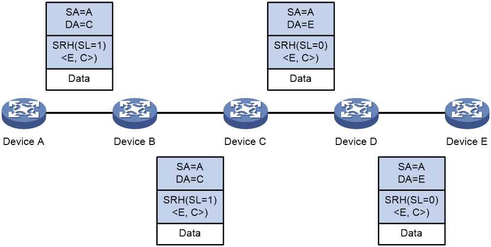
As shown in Figure 5, a source node receives a packet that matches an SRv6 path. Device A is the source node, Device C and Device E are endpoint nodes, and Device B and Device D are transit nodes. The packet is forwarded through the SRv6 path as follows:
1. Upon receiving an IPv6 packet, Device A performs the following operations:
¡ Encapsulates an SRH to the packet. The packet must pass two segments to reach Device E, so the Segments Left (SL) in the SRH is set to 1 (the number of segments along the path minus 1). The Segment List contains Segment List [0]=E and Segment List [1]=C.
¡ Encapsulates an outer IPv6 header to the packet. The source address of the IPv6 header is an IP address on Device A and the destination address is determined by the SL value. On Device A, the SL value is 1, which points to the SID on Device C, so the destination address is the SID on Device C.
¡ Looks up the routing table based on the destination address of the outer IPv6 header and forwards the packet to Device B.
2. Device B looks up the routing table based on the destination address of the outer IPv6 header and forwards the packet to Device C.
3. Device C performs the following operations:
¡ Checks the SL value in the SRH and decreases the value by 1 if the SL value is greater than 0. Updates the destination address to the address pointed by the SL. In this example, the SL is 0, which points to the SID on Device E. Device C replaces the destination address in the outer IPv6 header with the SID on Device E.
¡ Looks up the routing table based on the destination address of the outer IPv6 header and forwards the packet to Device D.
4. Device D looks up the routing table based on the destination address of the outer IPv6 header and forwards the packet to Device E.
5. Device E checks the SL value in the SRH and finds that the value has decreased to 0. The device performs the following operations:
a. Decapsulates the packet by removing the outer IPv6 header and the SRH.
b. Forwards the original packet to the destination based on the destination address.
IS-IS SRv6 extension
IS-IS SRv6 mechanism
As shown in Table 1, to support SRv6, the IS-IS protocol must advertise the following types of SRv6 information:
· Locator information: Used for other nodes in the network to locate the node that advertises the SID information.
· SID information: Provides a detailed description of SID functions, for example, the Function bound to the SID.
Table 1 IS-IS extensions for SRv6
|
TLV name |
Function |
Location |
|
SRv6 Capabilities sub-TLV |
Advertises SRv6 capabilities. |
IS-IS Router CAPABILITY TLV |
|
Node MSD sub-TLV |
Advertises Maximum SID Depth (MSD), which is the maximum number of SIDs that can be included in the SID list. |
IS-IS Router CAPABILITY TLV |
|
SRv6 Locator TLV |
Advertises the SRv6 locator and its associated End SID. |
IS-IS packet, a top-level TLV introduced by SRv6. |
|
SRv6 End SID sub-TLV |
Advertises End SIDs. |
SRv6 Locator TLV |
|
SRv6 End.X SID sub-TLV |
Advertises End.X SIDs in a P2P network. |
IS-IS NBR TLV (such as 22, 23, 141, 222, and 223 in IS-IS). |
|
SRv6 LAN End.X SID sub-TLV |
Advertises End.X SIDs in a LAN. |
IS-IS NBR TLV (such as 22, 23, 141, 222, and 223 in IS-IS). |
|
SRv6 SID Structure Sub-Sub-TLV |
Advertises SRv6 SID formats. |
· SRv6 End SID sub-TLV · SRv6 End.X SID sub-TLV · SRv6 LAN End.X SID sub-TLV |
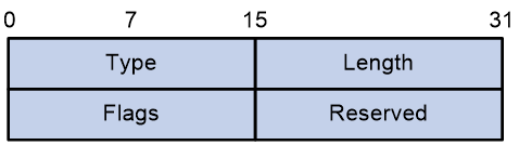
SRv6 Capabilities sub-TLV
Advertises a node's support for SRv6 capabilities, indicating the node can process the SRH.
The packet format for the SRv6 Capabilities sub-TLV is shown in Figure 6.
Figure 6 SRv6 Capabilities sub-TLV
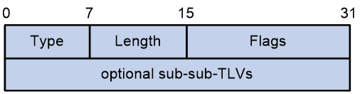
The SRv6 Capabilities sub-TLV contains fields as shown in Table 2.
Table 2 SRv6 Capabilities sub-TLV field description
|
Field Name |
length |
Description |
|
Type |
8-bit |
Type, with a value of 25. |
|
Length |
8-bit |
Length |
|
Flags |
16-bit |
Flag bit · C—Indicates support for SRv6 SID compression. · O—For OAM. |
|
optional sub-sub-TLVs |
Variable length. |
Optional sub-sub-TLV. |
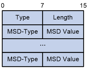
Node MSD sub-TLV
Advertises the maximum number of SIDs that a device MSD can include in the SID list.
The packet format for the Node MSD sub-TLV is shown in Figure 8.

The Node MSD sub-TLV contains fields as shown in Table 3.
Table 3 Node MSD sub-TLV field description
|
Field Name |
Length |
Description |
|
Type |
8-bit |
Type, with a value of 23. |
|
Length |
8-bit |
Length |
|
MSD-Type |
8-bit |
MSD type: · 41—SRH Max SL, the maximum value of the Segment Left field. · 42—SRH Max End Pop, the maximum number of SIDs that a node with PSP or USP can pop up. · 45—SRH Max End D, the maximum number of SIDs that an Endpoint node can decapsulate. |
|
MSD Value |
8-bit |
MSD value. |
SRv6 Locator TLV
Advertises the SRv6 locator and its associated End SID.
An SRv6 locator must be advertised through an SRv6 Locator TLV. Devices with IS-IS SRv6 capabilities will add the network segment route corresponding to the locator to their local routing table upon receiving the TLV, and devices without SRv6 capabilities will not add the route for the locator's network segment.
Locator-associated network segment routes can also be advertised through Prefix Reachability TLV (236/237) so that devices not supporting SRv6 can add route table entries and can interoperate with SRv6 nodes. If a device receives both a Prefix Reachability TLV and SRv6 Locator TLV, it prioritizes the Prefix Reachability TLV.
The packet format for the SRv6 Locator TLV is shown in Figure 8.
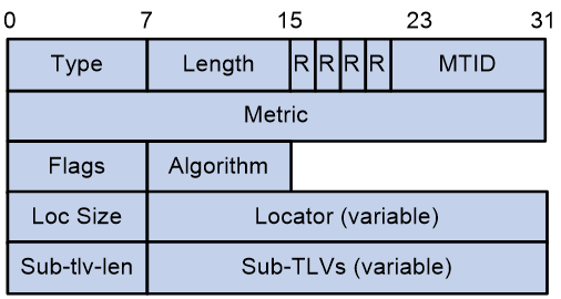
The SRv6 Locator TLV contains fields as shown in Table 4.
Table 4 SRv6 Locator TLV field description
|
Field Name |
Length |
Description |
|
Type |
8-bit |
Type, with a value of 27. |
|
Length |
8-bit |
Length |
|
MTID |
12-bit |
Multi-topology ID |
|
Metric |
8-bit |
Cost |
|
Flags |
8-bit |
Flag bit Only the D flag bit is defined. It must be set when an SID penetrates from Level-2 to Level-1. Once the D flag bit is set, the SID cannot penetrate from Level-1 to Level-2, preventing route loop. |
|
Algorithm |
8-bit |
Routing algorithm |
|
Loc Size |
8-bit |
Locator length |
|
Locator (variable) |
Variable length. |
Network prefix for the locator. |
|
Sub-tlv-len |
8-bit |
Sub-TLV length. |
|
Sub-TLVs (variable) |
Variable length. |
Contained Sub-TLVs, such as the SRv6 End SID sub-TLV. |
SRv6 End SID sub-TLV
Advertises End SIDs.
The packet format for the SRv6 End SID sub-TLV is shown in Figure 9.
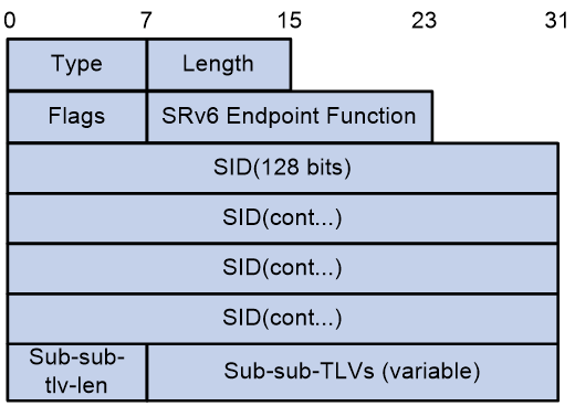
The SRv6 End SID sub-TLV contains fields as shown in Table 5.
Table 5 SRv6 End SID sub-TLV field description
|
Field name |
Length |
Description |
|
Type |
8-bit |
Type, with a value of 5. |
|
Length |
8-bit |
Length |
|
Flags |
8-bit |
Flag bit: · C—Advertises G-SIDs. |
|
SRv6 Endpoint Function |
16-bit |
For actions related to SRv6 SID binding, see "0SID portions." |
|
SID |
16-byte |
Advertised SRv6 SID. |
|
Sub-sub-tlv-len |
8-bit |
Sub-sub-TLV length. |
|
Sub-sub-TLVs (variable) |
Variable length. |
Contained Sub-sub-TLV. |
SRv6 End.X SID sub-TLV
Advertises a Point-to-Point (P2P) adjacency type End.X SID.
The packet format for the SRv6 End.X SID sub-TLV is shown in Figure 10.
Figure 10 SRv6 End.X SID sub-TLV
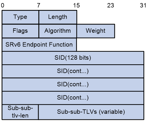
The SRv6 End.X SID sub-TLV contains fields as shown in Table 6.
Table 6 SRv6 End.X SID sub-TLV field description
|
Field name |
Length |
Description |
|
Type |
8-bit |
Type, with a value of 43. |
|
Length |
8-bit |
Length |
|
Flags |
8-bit |
Flag bit: · B (Backup)—The backup flag, used in the TI-LFA scenario. · S (Set)—The group flag. If set, it indicates that the End.X SID represents a set of adjacencies. · P (Persistent)—The persistent allocation flag. If set, it signifies that the End.X SID is permanently allocated. · C—Advertises G-SIDs. |
|
Algorithm |
8-bit |
Algorithm |
|
Weight |
8-bit |
Weight, not supported. |
|
SRv6 Endpoint Function |
16-bit |
For actions related to SRv6 SID binding, see "0SID portions." |
|
SID |
16-byte |
Advertised SRv6 SID. |
|
Sub-sub-tlv-len |
8-bit |
Sub-sub-TLV length. |
|
Sub-sub-TLVs (variable) |
Variable length. |
Contained Sub-sub-TLV. |
SRv6 LAN End.X SID sub-TLV
Advertises a LAN adjacency type End.X SID.
The packet format for the SRv6 LAN End.X SID sub-TLV is shown in Figure 11.
Figure 11 SRv6 LAN End.X SID sub-TLV
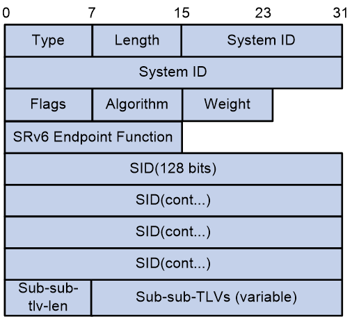
The SRv6 LAN End.X SID sub-TLV contains fields as shown in Table 7.
Table 7 SRv6 End.X SID sub-TLV field description
|
Field name |
Length |
Description |
|
Type |
8-bit |
Type, with a value of 44. |
|
Length |
8-bit |
Length |
|
System ID |
48-bit |
IS-IS System ID |
|
Flags |
8-bit |
Flag bit: · B (Backup)—The backup flag, used in the TI-LFA scenario. · S (Set)—The group flag. If set, it indicates that the End.X SID represents a set of adjacencies. · P (Persistent)—The persistent allocation flag. If set, it signifies that the End.X SID is permanently allocated. · C—Advertises G-SIDs. |
|
Algorithm |
8-bit |
Algorithm |
|
Weight |
8-bit |
Weight, not supported. |
|
SRv6 Endpoint Function |
16-bit |
For actions related to SRv6 SID binding, see "0SID portions." |
|
SID |
16-byte |
Advertised SRv6 SID. |
|
Sub-sub-tlv-len |
8-bit |
Sub-sub-TLV length. |
|
Sub-sub-TLVs (variable) |
Variable length. |
Contained Sub-sub-TLV. |
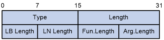
SRv6 SID Structure Sub-Sub-TLV
Advertises the format of an SRv6 SID, which specifies the length of each field within the SRv6 SID.
The packet format for the SRv6 SID Structure Sub-Sub-TLV is shown in Figure 12.
Figure 12 SRv6 SID Structure Sub-Sub-TLV
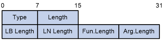
The SRv6 SID Structure Sub-Sub-TLV contains fields as shown in Table 8.
Table 8 SRv6 SID Structure Sub-Sub-TLV field description
|
Field name |
Length |
Description |
|
Type |
8-bit |
Type, with a value of 1. |
|
Length |
8-bit |
Length |
|
LB Length |
8-bit |
Block length for the locator, the common prefix length, for SID compression. |
|
LN Length |
8-bit |
The Node ID length in the locator, which is used to identify the node, is for SID compression. |
|
Fun.Length |
8-bit |
The length of the Function field in a SID. |
|
Arg.Length |
8-bit |
The length of the Arguments field in a SID. |
SRv6 Endpoint Function
SRv6 defines the actions bound to each SRv6 SID through Endpoint Functions. In addition to advertising locator network segment routes, another function completed by IS-IS is the advertisement of SRv6 SID information and the corresponding SRv6 Endpoint Function details via various IS-IS SID sub-TLVs to program the network. The types of Endpoint Functions supported by different SID sub-TLVs are shown as follows. Y indicates that the sub-TLV advertises this type of SRv6 Endpoint Function, and N indicates it does not.
Table 9 SRv6 Endpoint Function description
|
SRv6 Endpoint Function |
SRv6 End SID sub-TLV |
SRv6 End.X SID sub-TLV |
SRv6 LAN End.X SID sub-TLV |
|
End (no PSP, no USP) |
Y |
N |
N |
|
End (with PSP) |
Y |
N |
N |
|
End (with USP) |
Y |
N |
N |
|
End (with PSP & USP) |
Y |
N |
N |
|
End.X (no PSP, no USP) |
N |
Y |
Y |
|
End.X (with PSP) |
N |
Y |
Y |
|
End.X (with USP) |
N |
Y |
Y |
|
End.X (with PSP & USP) |
N |
Y |
Y |
|
End.DT4 |
Y |
N |
N |
|
End.DT6 |
Y |
N |
N |
|
End.DX4 |
N |
Y |
Y |
|
End.DX6 |
N |
Y |
Y |
|
End.OP |
Y |
N |
N |
|
End with COC |
Y |
N |
N |
|
End with PSP&COC |
Y |
N |
N |
|
End with PSP&USP&COC |
Y |
N |
N |
|
End.X with COC |
N |
Y |
Y |
|
End.X with PSP&COC |
N |
Y |
Y |
|
End.X with PSP&USP&COC |
N |
Y |
Y |
|
End with PSP&USD&COC |
Y |
N |
N |
|
End with PSP&USP&USD&COC |
Y |
N |
N |
|
End.X with PSP&USD&COC |
N |
Y |
Y |
G-SRv6
Technical background
In an SRv6 TE policy scenario, the administrator must add the 128-bit SRv6 SIDs of SRv6 nodes on the packet forwarding path into the SID list of the SRv6 TE policy. If the packet forwarding path is long, a large number of SRv6 SIDs will be added to the SID list of the SRv6 TE policy. This greatly increases the size of the SRv6 packet header, resulting in low device forwarding efficiency and reduced chip processing speed. The situation might be worse in a scenario that spans across multiple ASs where a much greater number of end-to-end SRv6 SIDs exist. For more information about SRv6 TE Policy, see SRv6 TE Policy Technology White Paper.
Generalized SRv6 (G-SRv6) encapsulates shorter SRv6 SIDs (G-SIDs) in the segment list of SRH by compressing the 128-bit SRv6 SIDs. This reduces the size of the SRv6 packet header and improves the efficiency for forwarding SRv6 packets. In addition, G-SRv6 supports both 128-bit SRv6 SIDs and G-SIDs in a segment list.
About G-SRv6
Typically, an address space is reserved for SRv6 SID allocation in an SRv6 subnet. This address space is called an SID space. In the SRv6 subnet, all SIDs are allocated from the SID space. The SIDs have the same prefix (common prefix). The SID common prefix is redundant information in the SRH.
G-SRv6 removes the common prefix and carries only the variable portion of SRv6 SIDs (G-SIDs) in the segment list, effectively reducing the SRv6 packet header size. To forward a packet according to routing table lookup, SRv6 replaces the destination IP address of the packet with the combination of the G-SID and common prefix in the segment list of the SRH.
With the compression efficiency and network scale taken into consideration, the ideal length of SRv6 SIDs is 32 bits after compression through G-SRv6.
G-SID format
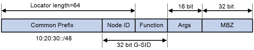
As shown in Figure 13, the locator portion of an SRv6 SID contains the Common Prefix and Node ID portions. The Common Prefix portion represents the address of the common prefix. The Node ID portion identifies a node. G-SRv6 can compress all SIDs with the same common prefix into 32-bit G-SIDs. A G-SID contains the Node ID and Function portions of a 128-bit SRv6 SID. A 128-bit SRv6 SID is formed by the Common Prefix portion, a 32-bit G-SID, and the 0 (Args&MBZ) portion.
Figure 13 Compressible SRv6 SID
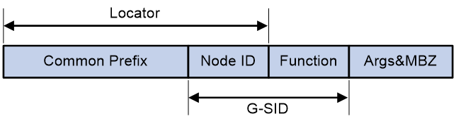
As shown in Figure 14, the length of the locator portion is 64, the common prefix is 10:20:30::/48, and the length of the Args portion is 16. The total length of the three portions is 96 bits. Therefore, the length of the MBZ portion is 128-96=32 bits.
G-SRv6 packet
G-SRv6 packet format
Figure 15 G-SRv6 packet format
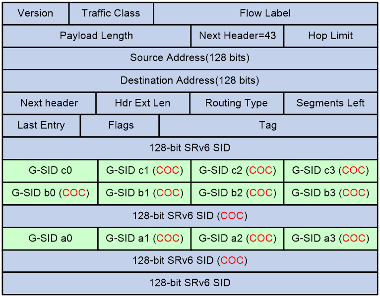
If the SRv6 SID of the next node requires compression, the routing protocol adds the COC flag to the advertised SRv6 SID of the local node. The COC flag indicates that the next SRv6 SID is a G-SID. A COC flag only identifies the forwarding behavior of an SRv6 SID, and is not actually carried in the packet.
As shown in Figure 15, G-SRv6 can encapsulate both G-SIDs and 128-bit SRv6 SIDs in the segment list of the SRH. It must encapsulate four G-SIDs in a group to the original location of a 128-bit SRv6 SID. If the location contains fewer than four G-SIDs (less than 128 bits), G-SRv6 pads the remaining bits with 0s. Multiple consecutive G-SIDs form a compressed path, called a G-SID list. A G-SID list can contain one or more groups of G-SIDs.
The G-SIDs in the segment list are arranged as follows:
1. The SRv6 SID before the G-SID list is a 128-bit SRv6 SID with the COC flag, indicating that the next SID is a 32-bit G-SID.
2. Except the last G-SID, all G-SIDs in the G-SID list must carry the COC flag to indicate that the next SID is a 32-bit G-SID.
3. The last G-SID in the G-SID list must be a 32-bit G-SID without the COC flag, indicating that the next SID is a 128-bit SRv6 SID.
4. The next SID is a 128-bit SRv6 SID, which can be an SRv6 SID with or without the COC flag.
Calculating the destination address with G-SID
Figure 16 Destination address calculated with G-SID
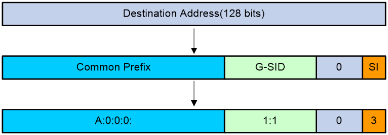
As shown in Figure 16, G-SRv6 combines the G-SID and Common Prefix in the segment list to form a new destination address.
· Common Prefix—Common prefix address manually configured by the administrator.
· G-SID—Compressed 32-bit SID obtained from the SRH.
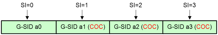
· SID Index (SI)—Index that identifies a G-SID in a group of G-SIDs. This field is the least significant two bits of the destination IPv6 address. The value range is 0 to 3. The SI value decreases by 1 at each node that performs SID compression. If the SI value becomes 0, the SL value decreases by 1. In a group of G-SIDs in the segment list, the G-SIDs are arranged from left to right based on SI values. The SI value is 0 for the leftmost G-SID, and is 3 for the rightmost G-SID.
Figure 17 Locating a SID by SI
· 0—If the total length of the Common Prefix, G-SID, and SI portions is less than 128 bits, the deficient bits are padded with 0s before the SI portion.
Suppose the following conditions exist:
· The Common Prefix deployed on the SRv6 node is A:0:0:0::/64.
· The G-SID in the SRv6 packet is 1:1.
· The SI value associated with the G-SID is 3.
Upon receiving the G-SRv6 packet, the SRv6 node calculates the destination address for the packet as follows:
· If the destination address of the packet is a 128-bit SRv6 SID with the COC flag in the segment list, the next SID is a G-SID. The device decreases the SI value by 1 and searches for the G-SID group corresponding to [SI-1]. Then, the device calculates the destination address based on the 32-bit G-SID identified by SI value 3.
· If the destination address of the packet is a 32-bit SRv6 SID with the COC flag in the segment list, the next SID is a G-SID.
¡ If the SI value is larger than 0, the device decreases the SI value by 1 and searches for the G-SID group corresponding to SL value of the packet. Then, the device calculates the destination address based on the 32-bit G-SID identified by [SI-1].
¡ If the SI value is equal to 0, the device decreases the SL value by 1, resets the SI value to 3, and searches for the G-SID group corresponding to the SL value of the packet. Then, the device calculates the destination address based on the 32-bit G-SID identified by SI value 3.
· If the destination address of the packet is a 32-bit SRv6 SID without the COC flag in the segment list, the device decreases the SL value by 1 and searches for the 128-bit SRv6 SID corresponding to [SL-1]. Then, the device replaces the destination address in the IPv6 header with the SRv6 SID.
· If the destination address of the packet is a 128-bit SRv6 SID without the COC flag in the segment list, the device decreases the SL value by 1 and searches for the 128-bit SRv6 SID corresponding to [SL-1]. Then, the device replaces the destination address in the IPv6 header with the SRv6 SID.
BGP-EPE
About BGP-EPE
IGP for SRv6 cannot advertise SRv6 SIDs across ASs. To advertise SRv6 SIDs across ASs, use BGP Egress Peer Engineering (BGP-EPE).
BGP-EPE can allocate BGP peer SIDs to inter-AS segments.
BGP-EPE allocates SIDs for inter-AS paths, known as BGP Peer SIDs. BGP Peer SIDs can be communicated to a controller through BGP LS extensions. The controller orchestrates IGP SIDs and BGP Peer SIDs to deploy end-to-end SRv6 paths.
BGP Peer SID
BGP-EPE supports automatic peer SID allocation and static peer SID allocation.
BGP-EPE can allocate the following peer SIDs:
· PeerNode SID—Identifies a peer node. BGP-EPE allocates a PeerNode SID to each BGP session. If the device establishes EBGP peer relationship with a peer through a loopback interface, it might have multiple physical links to reach the peer. In this case, the PeerNode SID for this peer is associated with multiple output interfaces. Traffic destined for this peer based on the PeerNode SID will be distributed among these output interfaces.
· PeerAdj SID—Identifies an adjacency link that can reach a peer node. If the device establishes EBGP peer relationship with a peer through a loopback interface, it might have multiple physical links to reach the peer. Each link is allocated a PeerAdj SID. When the device forwards traffic based on a PeerAdj SID, the traffic is forwarded out of the interface that is attached to the link identified by the PeerAdj SID.
· PeerSet SID—Identifies a group of peer nodes in a BGP-EPE SRv6 peer set. A PeerSet SID corresponds to multiple PeerNode SIDs and PeerAdj SIDs. When the device forwards traffic based on a PeerSet SID, it distributes the traffic among multiple peers.
Figure 18 BGP-EPE network diagram
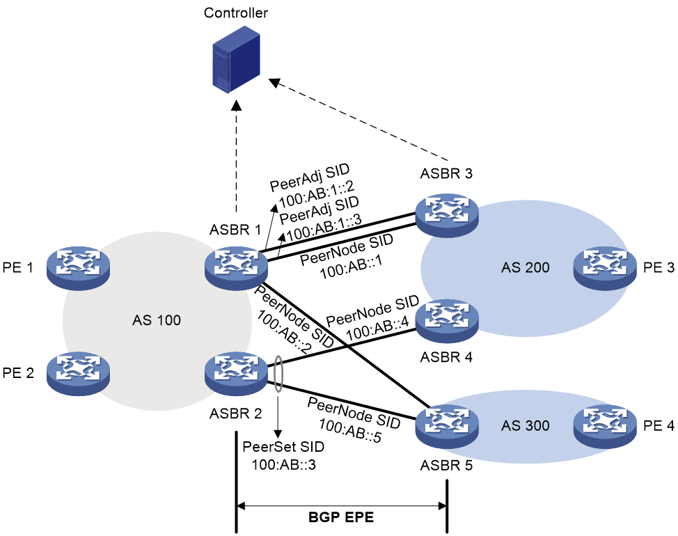
As shown in Figure 17, BGP-EPE allocates peer SIDs as follows:
· ASBR 1 and ASBR 3 have two direct physical links. They establish EBGP peer relationship through loopback interfaces. On ASBR 1, BGP-EPE allocates PeerNode SID 100:AB::1 to ASBR 3 and allocates PeerAdj SIDs 100:AB:1::2 and 100:AB:1::3 to the physical links. When ASBR 1 forwards traffic to ASBR 3 based on the PeerNode SID, the two physical links load share the traffic.
· EBGP peer relationship has been established between ASBR 1 and ASBR 5, between ASBR 2 and ASBR 4, and between ASBR 2 and ASBR 5 through directly connected physical interfaces. On ASBR 1, BGP-EPE allocates PeerNode SID 100:AB::2 to ASBR 5. On ASBR 2, BGP-EPE allocates PeerNode SIDs 100:AB::4 and 100:AB::5 to ASBR 4 and ASBR 5, respectively.
· ASBR 4 and ASBR 5 each have established EBGP peer relationship with ASBR 2. On ASBR 2, peers ASBR 4 and ASBR 5 are added to a peer set. BGP-EPE allocates PeerSet SID 100:AB::3 to the peer set. When ASBR 2 forwards traffic based on the PeerSet SID, the traffic is distributed to both ASBR 4 and ASBR 5 for load sharing.
BGP-EPE mechanism
In an inter-AS SRv6 network, advertising a combination of intra-AS SRv6 SIDs and inter-AS Peer SIDs can achieve optimal path forwarding across ASs.
Figure 19 BGP-EPE network diagram
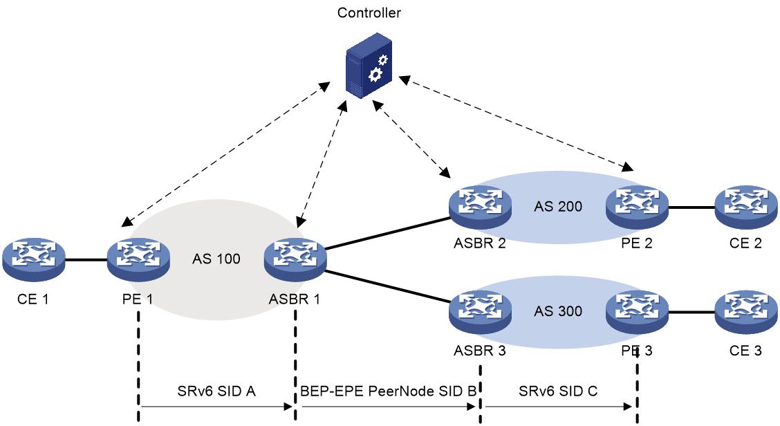
As shown in Figure 18, establish an inter-AS SRv6 path between PE 1 and PE 2, which includes the following components:
· The path from PE 1 to ASBR 1, which is SRv6 SID A.
· The path from ASBR 1 to ASBR 2, which is the PeerNode SID B allocated by BGP-EPE.
· The path from ASBR 2 to PE 2, which is SRv6 SID C.
After orchestrating intra-AS and inter-AS SIDs, the controller distributes the SRv6 path (SID list {A, B, C}) to the source node PE 1, enabling traffic forwarding along the path PE 1->ASBR 1->ASBR 2->PE 2.
BGP LS for SRv6
BGP LS for SRv6 application scenario
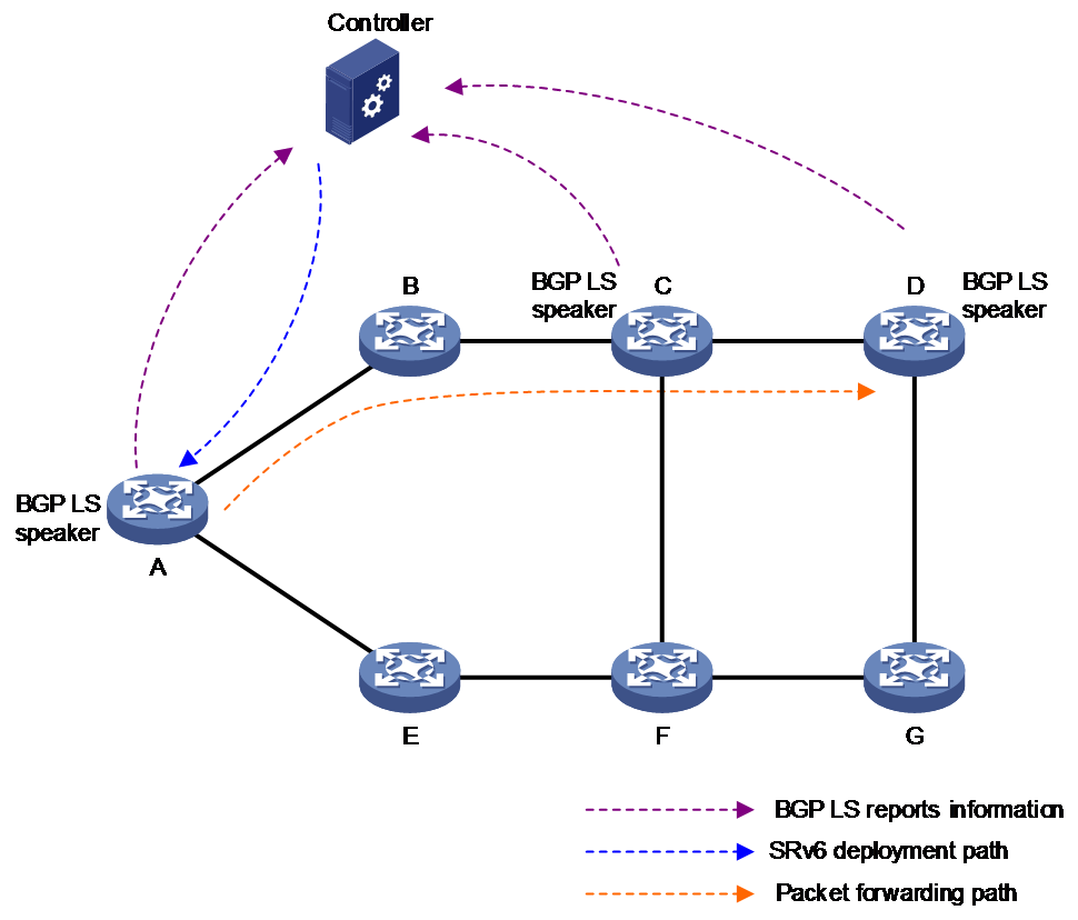
As shown in Figure 20, in an SRv6 network, SRv6 nodes typically report link state, SID, and candidate paths for SRv6 TE Policy to the controller by using BGP LS routes. The controller calculates the optimal path based on the reported information and issues it to the source node to guide packet forwarding along the SRv6 path.
A node that advertises BGP LS routes with SRv6 is called a BGP LS Speaker.
Figure 20 BGP LS for SRv6 typical networking
BGP-LS for SRv6 route extension
About route extension
To support SRv6, BGP-LS has newly defined an SRv6 SID NLRI for advertising and collecting network layer reachability information of SRv6 SIDs. The packet format of SRv6 SID NLRI is shown as in Figure 21.
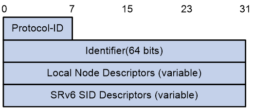
The SRv6 SID NLRI contains fields as shown in Table 10.
Table 10 SRv6 SID NLRI field description
|
Field name |
Length |
Description |
|
Protocol-ID |
8-bit |
Protocol ID. BGP-LS learns the SRv6 SID information of a node through the specified protocol. · 1—IS-IS Level 1. · 2—IS-IS Level 2. · 4—Directly connected route. · 5—Static route. · 6—OSPFv3. · 7—BGP. |
|
Identifier |
64-bit |
Node ID |
|
Local Node Descriptors |
Variable length. |
Local node description. |
|
SRv6 SID Descriptors |
Variable length. |
SRv6 SID information, which must contain the SRv6 SID Information TLV. |
BGP-LS defines new sub-TLVs within the existing Node NLRI, Link NLRI, and Prefix NLRI to advertise SRv6-related information.
The extensions of BGP-LS for SRv6 are shown in Table 11.
Table 11 BGP-LS for the SRv6 extension
|
TLV name |
Function |
Location |
|
SRv6 Capabilities TLV |
Advertises SRv6 capabilities. |
BGP-LS Node NLRI |
|
SRv6 Node MSD Types |
Advertises the maximum number of SIDs (MSD) that can be included in the SID list. Not a new TLV, but a new type added on the basis of the Node MSD TLV. |
BGP-LS Node NLRI |
|
SRv6 End.X SID TLV |
Advertises End.X SIDs. In a BGP-EPE network, this TLV can also be used to advertise the Peer-Adj-SID, which is the End.X SID of a BGP EPE Peer. |
BGP-LS Link NLRI |
|
SRv6 LAN End.X SID TLV |
Advertises the End.X SID of the broadcast network adjacency type. |
BGP-LS Link NLRI |
|
SRv6 Link MSD Types |
Advertises the maximum number of SIDs (MSD) that can be included in the Annc link SID list. Not a new TLV, but a new type added on the basis of the Link MSD TLV. |
BGP-LS Link NLRI |
|
SRv6 Locator TLV |
Advertises locator information. |
BGP-LS Prefix NLRI |
|
SRv6 SID Information TLV |
Advertises SRv6 SIDs. |
BGP-LS SRv6 SID NLRI |
|
SRv6 Endpoint Behavior TLV |
Advertises SRv6 SID types. |
BGP-LS SRv6 SID NLRI |
|
SRv6 BGP Peer Node SID TLV |
Advertises BGP Peer Node SID and BGP Peer Set SID in BGP-EPE networking. This TLV must be used together with the SRv6 End.X SID associated with the BGP Peer Node or Peer Set feature. |
BGP-LS SRv6 SID NLRI |
|
SRv6 SID Structure TLV |
Advertises the SRv6 SID format, which defines the length of each SID component. |
BGP-LS SRv6 SID NLRI optional TLV, SRv6 End.X, IS-IS SRv6 LAN End.X, OSPFv3 SRv6 LAN End.X TLVs' sub-TLV |
SRv6 Capabilities TLV
An SRv6 Capabilities TLV advertises that a node supports SRv6 features, meaning the node can process SRH.
The packet format for the SRv6 Capabilities TLV is shown in Figure 22.
Figure 22 SRv6 Capabilities TLV
The SRv6 Capabilities TLV contains fields as shown in Table 12.
Table 12 SRv6 Capabilities TLV field description
|
Field name |
Length |
Description |
|
Type |
16-bit |
Type, with a value of 1038. |
|
Length |
16-bit |
Length |
|
Flags |
16-bit |
Flag bit: · O—For OAM. |
|
Reserved |
16-bit |
Reserved value, set to 0. |
SRv6 Node MSD Types
An SRv6 Node MSD Types advertises the maximum number of SIDs that can be included in the SID list.
The packet format for the SRv6 Node MSD Types is shown in Figure 23.
The SRv6 Node MSD Types TLV includes fields as shown in Table 13.
Table 13 SRv6 Node MSD Types field description
|
Field name |
Length |
Description |
|
Type |
8-bit |
Type, with a value of 23. |
|
Length |
8-bit |
Length |
|
MSD-Type |
8-bit |
MSD type: · 41—SRH Max SL, the maximum value of the Segment Left field. · 42—SRH Max End Pop, the maximum number of SIDs that a node with PSP or USP can pop up. · 45—SRH Max End D, the maximum number of SIDs that an Endpoint node can decapsulate. |
|
MSD Value |
8-bit |
MSD value. |
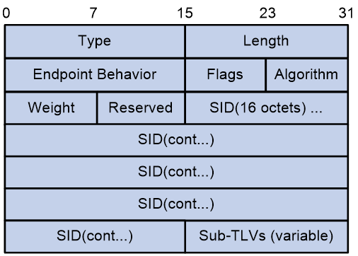
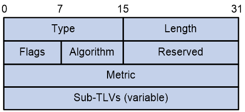
SRv6 End.X SID TLV
An SRv6 End.X SID TLV advertises End.X SIDs.
The packet format for the SRv6 End.X SID TLV is shown in Figure 24.
Figure 24 SRv6 End.X SID TLV
The SRv6 End.X SID TLV contains fields as shown in Table 14.
Table 14 SRv6 End.X SID TLV field description
|
Field name |
Length |
Description |
|
Type |
16-bit |
Type, with a value of 1106. |
|
Length |
16-bit |
Length |
|
Endpoint Behavior |
16-bit |
SRv6 SID type: · End SID · End.X SID · End.T SID · End.DX6 SID · End.DX4 SID · End.DT6 SID · End.DT4 SID · End.DX2 SID · End.DX2V SID · End.DT2U SID · End.DT2M SID |
|
Flags |
8-bit |
Flag bit: · B (Backup)—The backup flag, used in the TI-LFA scenario. · S (Set)—The group flag. If set, it indicates that the End.X SID represents a set of adjacencies. · P (Persistent)—The persistent allocation flag. If set, it signifies that the End.X SID is permanently allocated. |
|
Algorithm |
8-bit |
Algorithm |
|
Weight |
8-bit |
Weight, not supported. |
|
Reserved |
16-bit |
Reserved value, set to 0. |
|
SID |
16-byte |
Advertised SRv6 SID. |
|
Sub-TLVs (variable) |
Variable length. |
Contained Sub-TLV. |
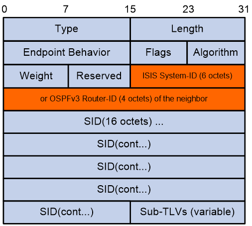
SRv6 LAN End.X SID TLV
An SRv6 LAN End.X SID TLV advertises a broadcast adjacency type End.X SID.
The packet format for the SRv6 LAN End.X SID TLV is shown in Figure 25.
Figure 25 SRv6 LAN End.X SID TLV
The SRv6 LAN End.X SID TLV contains fields as shown in Table 15.
Table 15 SRv6 LAN End.X SID TLV field description
|
Field name |
Length |
Description |
|
Type |
16-bit |
Type · 1107—Advertises IS-IS link state information, carrying the IS-IS System ID. · 1108—Advertises OSPFv3 link state information, carrying the OSPFv3 Router-ID. |
|
Length |
16-bit |
Length |
|
Endpoint Behavior |
16-bit |
SRv6 SID type: · End SID · End.X SID · End.T SID · End.DX6 SID · End.DX4 SID · End.DT6 SID · End.DT4 SID · End.DX2 SID · End.DX2V SID · End.DT2U SID · End.DT2M SID |
|
Flags |
8-bit |
Flag bit: · B (Backup)—The backup flag, used in the TI-LFA scenario. · S (Set)—The group flag. If set, it indicates that the End.X SID represents a set of adjacencies. · P (Persistent)—The persistent allocation flag. If set, it signifies that the End.X SID is permanently allocated. |
|
Algorithm |
8-bit |
Algorithm |
|
Weight |
8-bit |
Weight, not supported. |
|
Reserved |
16-bit |
Reserved value, set to 0. |
|
ISIS System-ID (6 octets) or OSPFv3 Router-ID (4 octets) of the neighbor |
48-bit or 32-bit |
IS-IS System ID or OSPFv3 Router-ID |
|
SID |
16-byte |
Advertised SRv6 SID. |
|
Sub-TLVs (variable) |
Variable length. |
Contained Sub-TLV. |
SRv6 Link MSD Types
An SRv6 Link MSD Types advertises the maximum number of SIDs that can be included in the SID list, with the same format as SRv6 Node MSD Types.
SRv6 Locator TLV
An SRv6 Locator TLV collects a node's locator information.
The packet format for the SRv6 Locator TLV is shown in Figure 26.
The SRv6 Locator TLV contains fields as shown in Table 16.
Table 16 SRv6 Locator TLV field description
|
Field name |
length |
Description |
|
Type |
16-bit |
Type, with a value of 1162. |
|
Length |
16-bit |
Length |
|
Flags |
8-bit |
Flag bit: · D flag bit—The Locator network segment routes cannot penetrate into IGP. · A flag bit—The Locator is an Anycast Locator, meaning a group of SRv6 nodes share the same locator. |
|
Algorithm |
8-bit |
Algorithm |
|
Reserved |
16-bit |
Reserved value, set to 0. |
|
Metric |
32-bit |
Cost |
|
Sub-TLVs (variable) |
Variable length. |
Contained Sub-TLVs, such as the SRv6 End SID sub-TLV. |
SRv6 SID Information TLV
The SRv6 SID Information TLV is a sub-TLV of SRv6 SID NLRI, used to advertise information related to SRv6 SID.
The packet format for the SRv6 SID Information TLV is shown in Figure 27.
Figure 27 SRv6 SID Information TLV
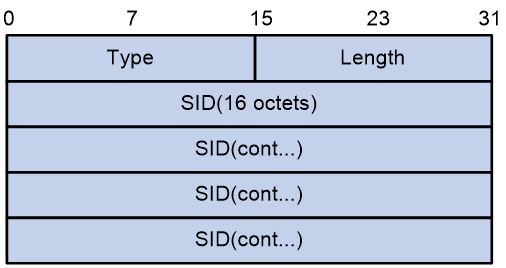
The SRv6 SID Information TLV contains fields as shown in Table 17.
Table 17 SRv6 SID Information TLV field description
|
Field name |
Length |
Description |
|
Type |
16-bit |
Type, with a value of 518. |
|
Length |
16-bit |
Length |
|
SID |
16-byte |
Advertised SRv6 SID. |
SRv6 Endpoint Behavior TLV
The SRv6 Endpoint Behavior TLV is a mandatory TLV that must be included in the BGP-LS properties associated with an SRv6 SID NLRI.
The packet format for the SRv6 Endpoint Behavior TLV is shown in Figure 28.
Figure 28 SRv6 Endpoint Behavior TLV
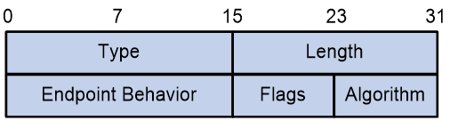
The SRv6 Endpoint Behavior TLV contains fields as shown in Table 18.
Table 18 SRv6 Endpoint Behavior TLV field description
|
Field name |
Length |
Description |
|
Type |
16-bit |
Type, with a value of 1250. |
|
Length |
16-bit |
Length |
|
Endpoint Behavior |
16-bit |
SRv6 SID type: · End SID · End.X SID · End.T SID · End.DX6 SID · End.DX4 SID · End.DT6 SID · End.DT4 SID · End.DX2 SID · End.DX2V SID · End.DT2U SID · End.DT2M SID |
|
Flags |
8-bit |
Flag bit: · B (Backup)—The backup flag, used in the TI-LFA scenario. · S (Set)—The group flag. If set, it indicates that the End.X SID represents a set of adjacencies. · P (Persistent)—The persistent allocation flag. If set, it signifies that the End.X SID is permanently allocated. |
|
Algorithm |
8-bit |
Algorithm |
SRv6 BGP Peer Node SID TLV
An SRv6 BGP Peer Node SID TLV advertises BGP Peer Node SID and BGP Peer Set SID in BGP-EPE networks. This TLV must be used in conjunction with the SRv6 End.X SID associated with BGP Peer Node or Peer Set functions.
The packet format for the SRv6 BGP Peer Node SID TLV is shown in Figure 29.
Figure 29 SRv6 BGP Peer Node SID TLV
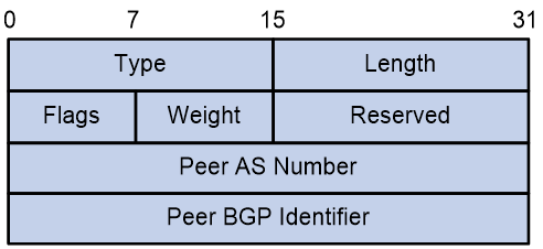
The SRv6 BGP Peer Node SID TLV contains fields as shown in Table 19.
Table 19 SRv6 BGP Peer Node SID TLV field description
|
Field name |
Length |
Description |
|
Type |
16-bit |
Type, with a value of 1251. |
|
Length |
16-bit |
Length |
|
Flags |
8-bit |
Flag bit: · B (Backup)—The backup flag, used in the TI-LFA scenario. · S (Set)—The group flag. If set, it indicates that the End.X SID represents a set of adjacencies. · P (Persistent)—The persistent allocation flag. If set, it signifies that the End.X SID is permanently allocated. |
|
Weight |
8-bit |
Weight value of the SID, not supported. |
|
Reserved |
16-bit |
Reserved value, set to 0. |
|
Peer AS Number |
32-bit |
Neighbor's AS number |
|
Peer BGP Identifier |
32-bit |
BGP neighbor's Router ID |
SRv6 SID Structure TLV
An SRv6 SID Structure TLV advertises the format of an SRv6 SID, which specifies the length of each field within the SRv6 SID.
The packet format for the SRv6 SID Structure TLV is shown in Figure 30.
Figure 30 SRv6 SID Structure TLV
The SRv6 SID Structure TLV contains fields as shown in Table 20.
Table 20 SRv6 SID Structure TLV field description
|
Field name |
Length |
Description |
|
Type |
8-bit |
Type |
|
Length |
8-bit |
Length |
|
LB Length |
8-bit |
The block length of a locator, which is the length of the common prefix, and is used for SID compression. |
|
LN Length |
8-bit |
The length of the Node ID in a locator, which identifies the node, and is used for SID compression. |
|
Fun.Length |
8-bit |
The length of the Function field in a SID. |
|
Arg.Length |
8-bit |
The length of the Arguments field in a SID. |
References
· draft-ietf-idr-bgpls-srv6-ext-05
· draft-ietf-bess-srv6-services-02
· draft-ietf-spring-srv6-network-programming-16
· draft-ietf-6man-spring-srv6-oam-05
· draft-ietf-lsr-isis-srv6-extensions-08
· RFC 8667: IS-IS Extensions for Segment Routing
· RFC 8754: IPv6 Segment Routing Header (SRH)
