- Released At: 18-12-2024
- Page Views:
- Downloads:
- Table of Contents
- Related Documents
-
SR-MPLS Technology White Paper
Copyright © 2024 New H3C Technologies Co., Ltd. All rights reserved.
No part of this manual may be reproduced or transmitted in any form or by any means without prior written consent of New H3C Technologies Co., Ltd.
Except for the trademarks of New H3C Technologies Co., Ltd., any trademarks that may be mentioned in this document are the property of their respective owners.
This guide describes only the most common information for lightning protection. Some information might not be applicable to your products.
Contents
Prefix SID-based packet forwarding within the same AS
Adjacency SID-based packet forwarding
Prefix and adjacency SID-based packet forwarding
Configuring a controller to calculate routes and create an SR-MPLS TE tunnel
Configuring an explicit path to create an SR-MPLS TE tunnel
Traffic steering to an SR-MPLS tunnel
IGP SR and LDP interworking mechanism
Interoperability between BGP SR and non-SR label forwarding networks
Basic concepts of SR-MPLS TE Policy
SR-MPLS TE policy routing procedure
SR-MPLS TE policy traffic forwarding
Traffic steering to an SR-MPLS TE policy
MP-BGP extension for SR-MPLS TE policy-based routing
Collaboration between SR-BE LSP and SBFD
Collaboration between SR-MPLS TE and SBFD
Collaboration between SR-MPLS TE Policy and SBFD
Microloop avoidance after a network failure
Microloop avoidance after a failure recovery
About SR-MPLS
Technical background
The development of cloud computing poses new challenges to WANs, demanding a transformation of traditional WAN infrastructure. SD-WAN, as the core technology for WAN reconstruction, accelerates network delivery, optimizes application experience, increases bandwidth utilization, and simplifies network operations through automatic deployment, centralized control, intelligent scheduling, and visualization, thus fulfilling the WAN requirements of cloud computing.
Intelligent scheduling is a key capability of the next-generation WAN, crucial for ensuring application quality and optimizing bandwidth resources. Existing traffic engineering technologies such as MPLS and RSVP-TE can meet differentiated bandwidth requirements for applications, but they face issues such as protocol variety, complex deployment, difficult management, and poor scalability. They cannot fulfill the dynamic deployment, flexible scheduling, rapid response, and scalability demanded by the new WAN generation. Consequently, a new protocol called Segment Routing has emerged.
Segment Routing (SR) is a source routing technology. The source node selects a path for the packets, and then encodes the path in the packet header as an ordered list of segments. Each segment is identified by a label called the segment identifier (SID). The SR nodes along the path forward the packets based on the SIDs in the packets. Only the source node needs to maintain the path status.
SR can operate with MPLS. In an MPLS network, SR uses MPLS labels as SIDs to forward packets on an LSP.
SR-MPLS effectively inherits the advantages of MPLS technology while adapting to future developments such as SDN, offering a flexible and efficient control method for SD-WAN networks. SR-MPLS is simple to use and easy to expand, enhancing traffic scheduling and path optimization, ensuring the quality of critical services, balancing traffic distribution, increasing private line utilization, and reducing line costs.
Benefits
SR-MPLS is simple, efficient, and easily expandable, offering many unparalleled advantages.
· A protocol designed for SDN architecture, integrating the advantages of autonomous device forwarding and centralized programming control to better achieve application-driven networking. It also natively supports traditional and SDN networks, is compatible with existing devices, and ensures smooth network evolution.
· It simplifies the control plane of devices, reduces the number of routing protocols, streamlines operations and maintenance management, and lowers operational costs. The scale of label forwarding tables that need to be maintained in an SR-MPLS network is small, with the number of forwarding tables on a device being N (number of node labels, generally equal to the total number of network nodes) + A (adjacency label data, generally equal to the number of device interfaces), in contrast to N^2 in traditional MPLS networks.
· SR-MPLS can be deployed in a wide range of scenarios, including backbone networks, DCI networks, and DC networks.
· It can simplify implementation of TE, FRR, and OAM, and therefore streamline network design and management, quickly delivering network services, and optimizing overall network performance.
Basic concepts of SR-MPLS
· SR node—A node enabled with the SR-MPLS feature. The ingress node (source node) adds labels to packets. The transit nodes forward packets based on labels. The egress node removes labels and forwards packets to the destination networks.
· SR domain—SR nodes form an SR domain.
· Segment—An instruction an SR node executes on the incoming packet, including inserting labels, switching labels, and popping-up labels.
· SID—Segment ID, which is MPLS label in SR-MPLS.
· Segment type—The following types of segments are available:
· Prefix segment—SIDs are assigned to nodes based on destination address prefix. The nodes create prefix-specific forwarding entries.
· Adjacency segment—SIDs are assigned to nodes based on adjacency.
· SRLSP—Segment routing label switched path, an LSP along which SR uses MPLS labels as SIDs to forward packets.
· SRGB—Segment routing global block, a range of global labels dedicated for SR-MPLS prefix SIDs. Different nodes can have different SRGBs. The minimum label value of an SRGB label range is referred to as the base value of the SRGB.
· SRLB—Segment routing local block, a range of local labels dedicated for SR-MPLS adjacency SIDs. All nodes share the same SRLB. The minimum label value of the SRLB label range is referred to as the base value of the SRLB.
Operating mechanism
To forward traffic over SRLSPs, SR-MPLS does the following:
· Label allocation for all nodes and links along the packet forwarding paths.
·Available methods include the following:
¡ Static segment configuration.
¡ Dynamic SID allocation: Allocate SIDs dynamically through IGP/BGP protocols, including IS-IS SR, OSPF SR, and BGP SR.
· Label forwarding entry installation based on SIDs. All SR-MPLS devices in the SR domain use the allocated labels to create label forwarding entries.
· SRLSP setup. You can manually configure SRLSPs, or use an IGP, BGP, or a controller to dynamically create SRLSPs.
· When the ingress node of an SRLSP receives a packet, it adds labels to the packet and forwards the packet to the egress node through the SRLSP. After receiving a packet from the SRLSP, the egress node removes the label and forwards the packet based on the routing table.
You can bind a higher layer application (for example, MPLS TE) to an SRLSP to forward traffic of the application through the SRLSP.
IGP SR
SR-MPLS expands IGP protocols such as IS-IS and OSPF to advertise SIDs in IGP protocol packets. SR-MPLS provides the following methods for dynamically allocating and advertising SIDs:
· Prefix SID.
· Adjacency SID.
Prefix SID
After you configure an SID for the loopback address on each SR node, the SIDs uniquely identify the SR nodes. All SR nodes in the SR domain use an IGP to advertise their own prefix SIDs. After receiving advertised prefix SIDs, each SR node calculates the prefix SIDs to the advertisers.
The prefix SID advertisement can be one of the following types:
· Absolute value advertisement—Each SR node advertises the prefix SID absolute value and the SRGB.
· Index value advertisement—Each SR node advertises the prefix SID index and the SRGB. Each SR node is assigned a globally unique index value for the node's prefix. The prefix SID an SR node allocates to a prefix equals the SRGB base of the SR node plus the index for that prefix.
The device supports only the index value advertisement in the current software release.
Other devices within the SR domain calculate local label forwarding entries based on the received route information. The incoming label is the base value of the local SRGB segment plus Index, and the outgoing label is the next hop's SRGB base value plus Index.
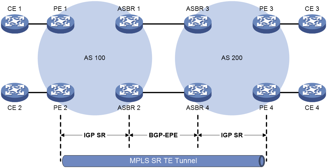
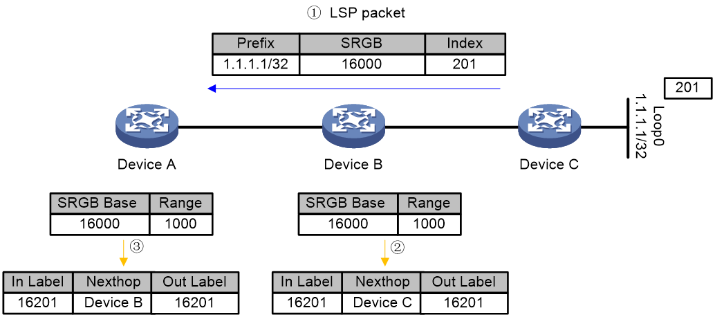
Figure 1 Label forwarding entry installation based on IGP prefix SIDs
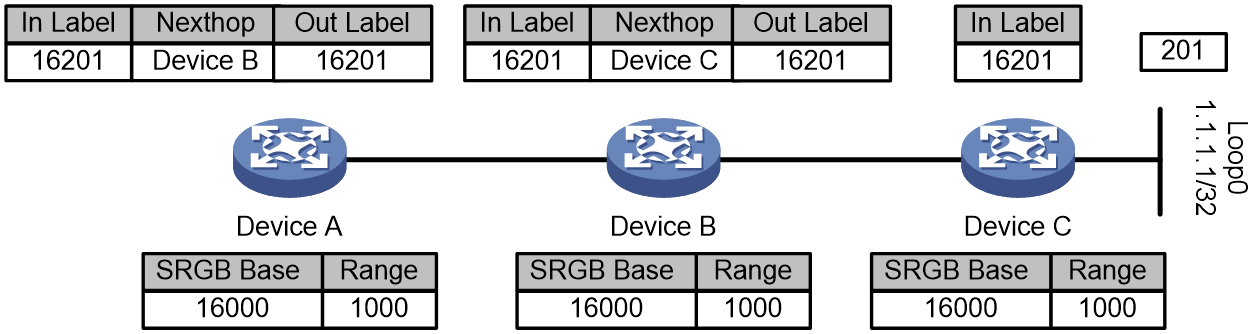
Figure 1 shows how dynamic label forwarding entries are created. After you assign index value 201 to loopback address 1.1.1.1/32 on Device C, Device C uses an IGP packet to advertise the index value and its local SRGB. Then, the devices calculate incoming and outgoing labels according to the previously mentioned label calculation rules.
1. Devices C calculates its incoming label, which is 16201.
2. Device B calculates its incoming label and outgoing label and creates a label forwarding entry. The incoming label is 16201. The outgoing label is 16201. The next hop is Device C.
3. Device A calculates its incoming label and outgoing label and creates a label forwarding entry. The incoming label is 16201. The outgoing label is 16201. The next hop is Device B.
Adjacency SID
SR nodes use an IGP to advertise SIDs allocated to the IGP adjacencies (that is, the links to its IGP neighbors). The SIDs are used to identify the links.
The adjacency SIDs can be allocated automatically or manually.
· Automatic adjacency SID allocation—SR nodes allocate labels in SRLBs to the IGP adjacencies as SIDs.
· Manual adjacency SID allocation—You can assign adjacency SIDs by using absolute values or index values. If you use index values, the adjacency SID of a link is the base value of the SRLB plus the index value for the link.
Figure 2 Label forwarding entry installation based on IGP adjacency SIDs
As shown in Figure 2, the devices are running the same IGP. After IGP adjacencies are established between the devices, Device A, Device B, and Device C allocates labels and creates label forwarding entries as follows:
1. Device A creates a label forwarding entry with incoming label 203 and next hop Device B.
2. Device B creates a label forwarding entry with incoming label 202 and next hop Device C.
3. Device C creates a label forwarding entry with incoming label 201 and next hop Device D.
IGP extension TLVs
To enable the advertisement of SID functionality in IGP protocol messages, some extensions are added to the IGP protocol packets.
· The IS-IS protocol primarily defines sub-TLVs for SID and network element SR capabilities.
¡ Prefix-SID Sub-TLV—Used for advertising SR prefix SIDs.
¡ Adj-SID Sub-TLV—Used for advertising SR Adjacency SIDs in a P2P network.
¡ LAN-Adj-SID Sub-TLV—Used for advertising Adjacency SIDs in a LAN network.
¡ SID/Label Sub-TLV—Used for advertising SR SIDs or MPLS labels.
¡ SID/Label Binding TLV—Used for advertising the mapping relationships of prefixes and SIDs.
¡ SR-Capabilities Sub-TLV—Used for advertising SR capabilities.
¡ SR-Algorithm Sub-TLV—Used for advertising the algorithms in use.
¡ SR Local Block Sub-TLV—Used for advertising the label range reserved for the local SID by the network element.
· The OSPF protocol defines TLVs and Sub-TLVs for SID and the SR capabilities of network elements.
¡ SR-Algorithm TLV—Used for advertising the algorithm in use.
¡ SID/Label Range TLV—Used for advertising the SIDs or MPLS label ranges for Segment Routing.
¡ SRMS Preference TLV—Used for advertising the priority of a network element as an SR Mapping Server.
¡ SID/Label Sub-TLV—Used for advertising SR SIDs or MPLS labels.
¡ Prefix-SID Sub-TLV—Used for advertising SR prefix SIDs.
¡ Adj-SID Sub-TLV—Used for advertising SR Adjacency SIDs in a P2P network.
¡ LAN-Adj-SID Sub-TLV—Used for advertising Adjacency SIDs in a LAN network.
BGP SR
BGP SR is an extension of the BGP protocol to allocate or advertise SIDs within or between ASs via BGP messages.
Based on the BGP protocol, SID allocation and advertisement methods can be divided into Prefix SID and BGP-EPE. Prefix SID can be carried when advertising prefix routes within or between ASs. BGP-EPE can only allocate Peer SIDs for BGP peers or inter-AS links, but Peer SIDs are only locally valid and cannot be advertised.
Prefix SID
BGP Prefix-SID packet format
The BGP protocol packets contain a new routing attribute, BGP Prefix-SID, which uses the defined TLV in BGP Prefix-SIDs to carry and advertise Prefix SID information and establish label forwarding table entries. The format of the BGP Prefix-SID routing attribute and related Prefix SID TLVs is as shown in Figure 3.
Figure 3 BGP Prefix-SID property and TLV structure
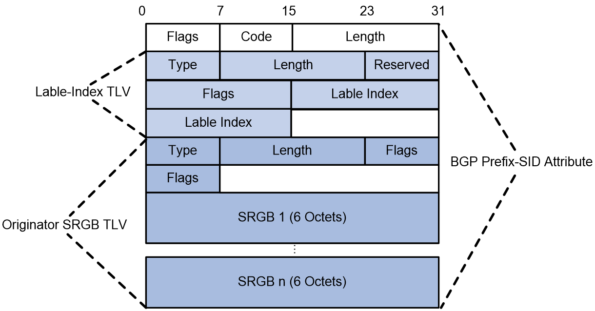
The BGP Prefix-SID property is carried in BGP Update packets, representing a route property extended by BGP to support Segment Routing.
· Flags—1 byte, which identifies whether the attribute is optional and transitive.
· Code—1 byte, with a value of 40, identifies the type of the route property.
· Length—2 byte, indicating the total length of the TLVs carried by the BGP Prefix-SID property.
In the SR-MPLS forwarding plane, the BGP Prefix-SID property carries two types of TLVs.
· Label-Index TLV
¡ Type—1-byte long with a value of 1.
¡ Length—2 bytes long, with a value of 7.
¡ Label-Index—4 bytes long, indicating the label index value of the Prefix SID.
· Originator SRGB TLV
¡ Type—1-byte long with a value of 3.
¡ Length—2 bytes long, with a value depending on the number of SRGB fields.
¡ SRGB—A 6-byte field that indicates the local starting value and range of the advertised Prefix SID for a BGP peer. The SRGB field might appear multiple times.
Prefix SID advertisement and label forwarding entry installation
BGP advertises Prefix SIDs by using the following two allocation methods:
· Distributes IGP routes into BGP, and uses the SID allocated by the IGP protocol for the route prefix when BGP advertises route prefixes to peers.
· Specify a routing policy when learning routes from a BGP peer to bind the SID with the route prefix by configuring the SID index value in the routing policy.
After the BGP protocol is extended, peers can advertise Prefix SIDs through protocol packets.
The device redistributes routes to BGP and assigns prefix SIDs to redistributed routes based on routing policies. Then, the device uses BGP to flood in the SR domain the prefix SIDs and the indexes of the prefix SIDs. Based on the flooded information, the other devices in the domain calculates their local label forwarding entries by using the following rules:
· Incoming label = Local SRGB base value + Index
· Outgoing label = Received SID
The Prefix SID information dynamically allocated through the BGP protocol can only be exchanged between BGP peers via IPv4 unicast routing, typically applied in inter-AS VPN-Option C networking scenarios.
Figure 4 Label forwarding entry installation based on BGP prefix SIDs
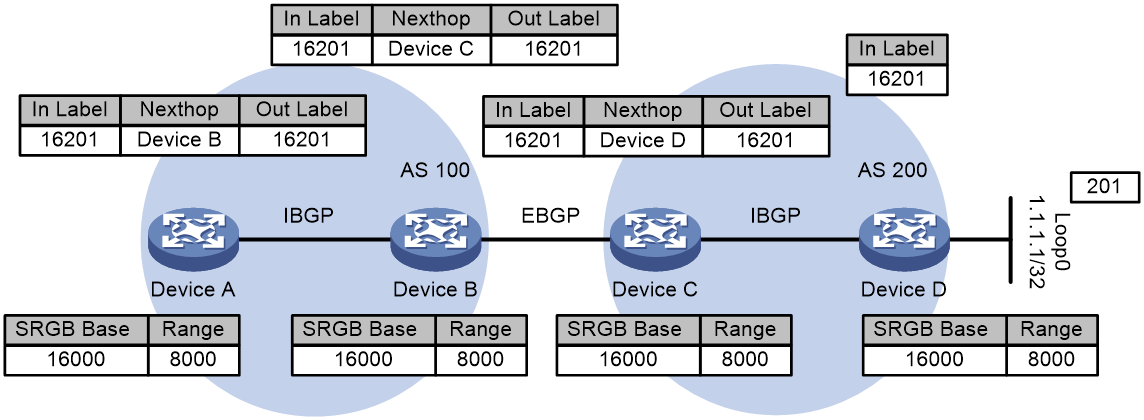
Figure 4 shows how label forwarding entries are created. After you assign index value 201 to loopback address 1.1.1.1/32 on Device D, Device D redistributes the route of the address and assigns it an SID (16201 in this example). Then, the device uses a BGP packet to advertise the SID and index value. The devices in the SR domain calculate incoming and outgoing labels according to the previously mentioned label calculation rules and create label forwarding entries.
· Devices D calculates its incoming label, which is 16201.
· Device C calculates its incoming label and outgoing label and creates a label forwarding entry. The incoming label is 16201. The outgoing label is 16201. The next hop is Device D.
· Device B calculates its incoming label and outgoing label and creates a label forwarding entry. The incoming label is 16201. The outgoing label is 16201. The next hop is Device C.
· Device A calculates its incoming label and outgoing label and creates a label forwarding entry. The incoming label is 16201. The outgoing label is 16201. The next hop is Device B.
BGP-EPE
The BGP Egress Peer Engineering (BGP-EPE) feature assigns BGP peering SIDs to segments across ASs. The device sends BGP peering SIDs to the controller through BGP-LS extensions. The controller orchestrates IGP SIDs and BGP peering SIDs for inter-AS forwarding over optimal paths.
You can manually specify the BGP peering SIDs to be assigned to the BGP peers or peer groups or enable the device randomly assign these SIDs.
· PeerNode SID—Identifies a peer node. Each BGP session is assigned a PeerNode SID. An EBGP peer session established based on a loopback interface might use multiple physical links. The PeerNode SID for the EBGP peer therefore might have multiple outgoing interfaces. The device will load-share traffic among these outgoing interfaces when it forwards the traffic based on the PeerNode SID.
· PeerAdj SID—Identifies an adjacency to a peer. An EBGP peer session established based on a loopback interface might use multiple physical links. Each physical link will be assigned a PeerAdj SID. The device forwards traffic through a specific outgoing interface when it forwards the traffic based on a PeerAdj SID.
· PeerSet SID—Identifies a set of peers. BGP-EPE supports adding a group of peers to a set and assigning the set a PeerSet SID. The device will load-share traffic among the peers in the set when it forwards the traffic based on a PeerSet SID. A PeerSet SID identifies the set of which PeerNode SIDs or PeerAdj SIDs are members.
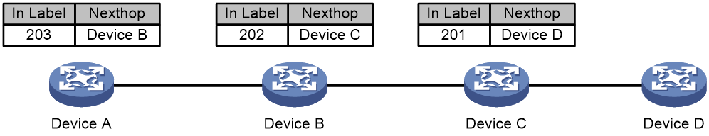
Figure 5 BGP-EPE network diagram
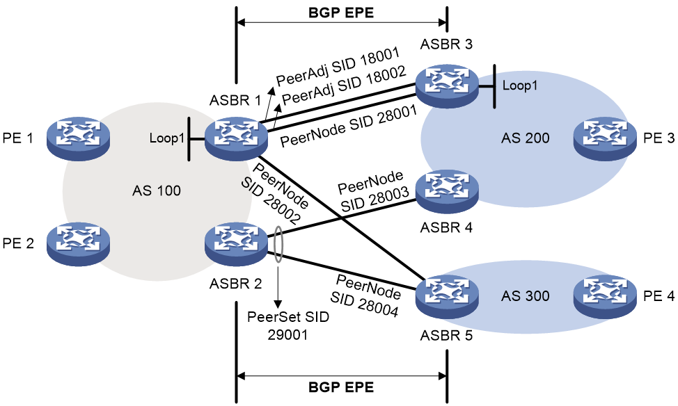
As shown in Figure 5, BGP-EPE allocates SID labels as follows:
· ASBR 1 and ASBR 3 are directly connected through two physical links. The two ASBRs establish an EBGP peer relationship with each other through loopback interfaces. BGP-EPE assigns PeerNode SID 28001 to the peer node and assigns PeerAdj SIDs 18001 and 18002 to the two physical links. Traffic between the two ASBRs will be load-shared on the two physical links when it is forwarded based on the PeerNode SID.
· An EBGP peer relationship is established over a physical link between ASBR 1 and ASBR 5, ASBR 2 and ASBR 4, and ASBR 2 and ASBR 5. BGP-EPE only assigns labels (PeerNode SIDs 28002, 28003, and 28004) to the peer nodes.
· ASBR 4 and ASBR 5 both establish an EBGP peer relationship with ASBR 2. BGP-EPE adds ASBR 4 and ASBR 5 to a BGP-EPE peer set and assigns the set PeerSet SID 29001. Traffic will be sent to the devices in the peer set for load sharing when it is forwarded based on the PeerSet SID.
SIDs that BGP-EPE assigns are locally significant. These SIDs are not advertised to other devices and are not affected by route types exchanged between BGP peers.
SID allocation through BGP-EPE is typically used for MPLS VPN inter-AS option B.
Configure BGP-EPE on the border router to allocate SIDs to the specified peer/peer group.
Figure 6 Configuring BGP-EPE to install label forwarding entries in an inter-AS SR-MPLS TE scenario
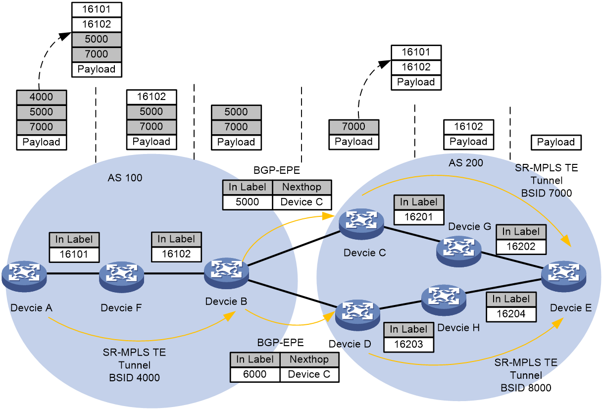
As shown in Figure 6, take the process of establishing inter-AS SR-MPLS TE label forwarding entries as an example:
· Create an SR-MPLS TE tunnel on Device A from Device A to Device B and bind BSID 4000. For more information about BSID, see "0Binding SID."
· Enable BGP-EPE on Device B and allocate PeerNode SIDs to EBGP neighbors Device C and Device D. Do this after establishing the EBGP neighbor relationship.
¡ Device B allocates PeerNode SID 5000 to its EBGP neighbor Device C, forming an SRLSP label forwarding entry with an ingress label of 5000 and Device C as the next hop.
¡ Device B allocates PeerNode SID 6000 to EBGP neighbor Device D, forming an SRLSP label forwarding entry with the ingress label 6000 and next hop as Device D.
· Create an SR-MPLS TE tunnel from Device C to Device E within the AS and bind it to BSID 7000 on Device C. Similarly, create an SR-MPLS TE tunnel from Device D to Device E within the AS and bind it to BSID 8000.
· Use Device A to establish an end-to-end tunnel to Device E by referencing the BSID of the SR-MPLS TE tunnel within the AS and the Peer SID. The tunnel path passing through Device C to Device E is (4000, 5000, 7000); the tunnel path passing through Device D to Device E is (4000, 6000, 8000).
Using the tunnel path from Device A through Device C to Device E as an example, the packet forwarding process is as follows:
1. On Device A, encapsulate traffic with an SRH extension header, defining an explicit path (4000, 5000, 7000). Use label 4000 to search the label forwarding entry and identify an SR-MPLS TE tunnel. The label stack represented by 4000 is (16101, 16102). Replace label 4000 with the explicit path labels (16101, 16102) from AS 100 and forward to Device B based on the AS's explicit path (16101, 16102).
2. After Device B pops up the explicit path label within AS 100, it checks the label forwarding table for 5000 to determine that the next hop corresponds to Device C. After the 5000 label is popped up, it transmits the packet to the next node, Device C.
3. The forwarding process of the intermediate node Device C is similar to that of node Device A. It passes the packet to Device E through an intra-AS tunnel.
Upon reaching the end node Device E, the device removes the intra-AS label from the packet and then looks up the FIB table to forward the packet based on its destination IP address.
SRLSP setup
You can use the following methods to create SRLSPs:
· Manually configure an SRLSP.
To configure an SRLSP, you must specify the label stack for packets to be forwarded along the SRLSP on the ingress node. Each label in the stack corresponds to a prefix SID or adjacency SID. The system can look for the outgoing label and next hop based on the prefix SID or adjacency SID.
· Configure SR nodes to use BGP or an IGP to dynamically establish an SRLSP.
SR nodes follow these steps to establish SRLSPs:
a. Use BGP or an IGP to collect prefix SID information from the SR-MPLS network.
b. Calculate the shortest paths to other SR nodes based on the collected prefix SID information and the BGP or IGP network topology.
c. Establish SRLSPs based on the shortest paths.
· Configure a controller to deploy SRLSP configuration to the device so the device creates SRLSPs. For more information about controller configuration, see the user guide for the controller.
Packet forwarding in SR-MPLS
Based on the SID allocation method, SR-MPLS uses one of the following packet forwarding methods:
· Prefix SID-based packet forwarding—The ingress node encapsulates the prefix SID for the egress node to a packet. The transit nodes forward the packet based on label forwarding entries.
· Adjacency SID-based packet forwarding—The ingress node encapsulates the label stack that contains the adjacency SIDs of all links along the forwarding path to a packet. Each transit node uses the top label in the label stack to determine the next hop and pops the top label before forwarding the packet to the next hop.
· Prefix and adjacency SID-based packet forwarding—The nodes use prefix SID-based packet forwarding in combination with adjacency-based packet forwarding.
Prefix SID-based packet forwarding within the same AS
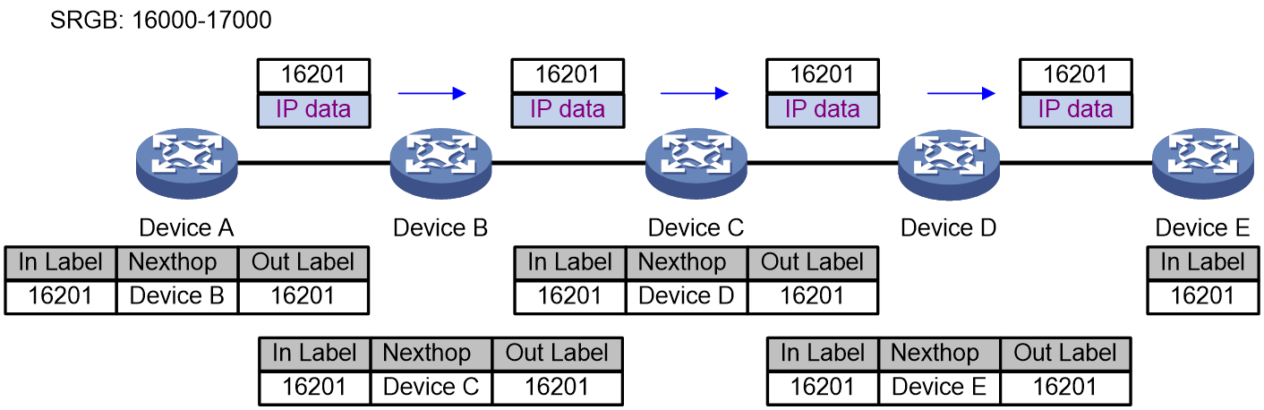
Figure 7 shows how a packet is forwarded along the SRLSP from Device A to Device E based on prefix SIDs. In this example, the outgoing label for the packet is 16201 on Device A.
1. Ingress node Device A searches for a forwarding entry for label 16201, adds outgoing label 16201 to the packet and sends the packet to the next hop (Device B).
2. When transit node Device B receives the packet, it searches for a label forwarding entry that matches the label in the packet. Then, Device B uses the outgoing label of the matched entry (16201) to replace the label in the packet and forwards the packet to the next hop (Device C).
3. Transit nodes Device C and Device D process the packet in the same way Device B does.
4. When egress node Device E receives the packet, it removes the label and forwards the packet by IP address.
Figure 7 Prefix SID-based packet forwarding within the same AS
Adjacency SID-based packet forwarding
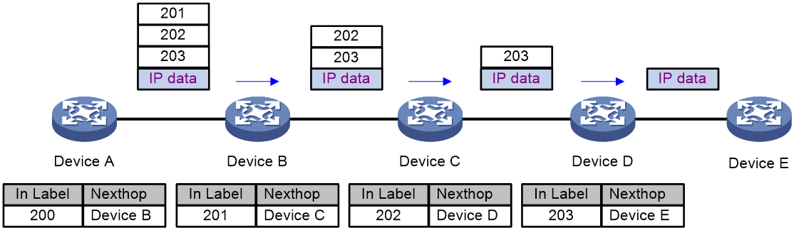
Figure 8 shows how a packet is forwarded along the SRLSP from Device A to Device E based on adjacency SIDs. In this example, the label stack for the packet is configured as (200, 201, 202, and 203) on Device A.
1. Ingress node Device A searches for a forwarding entry for the top label (200) to determine the next hop. Then, Device A adds label stack (201, 202, and 203) to the packet, and forwards the packet to the next hop (Device B).
2. When transit node Device B receives the packet, it searches for a forwarding entry for the top label (201) to determine the next hop. Then, Device B removes the top label from the stack and forwards the packet to the next hop (Device C).
3. When transit node Device C receives the packet, it searches for a forwarding entry for the top label (202) to determine the next hop. Then, Device C removes the top label from the stack and forwards the packet to the next hop (Device D).
4. When transit node Device D receives the packet, it searches for a forwarding entry for the label (203) to determine the next hop. Then, Device D removes the label stack from the packet and forwards the packet to the next hop (Device E).
5. When egress node Device E receives the packet, it forwards the packet by IP address.
Figure 8 Adjacency SID packet forwarding
Prefix and adjacency SID-based packet forwarding
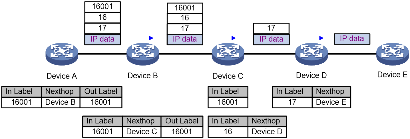
Figure 9 shows how a packet is forwarded along the SRLSP from Device A to Device E based on prefix SIDs and adjacency SIDs. In this example, the index value for the prefix SID of Device C is 1. The prefix SIDs for Device A, Device B, and Device C are all 16001. The Adjacency SIDs that Device C and Device D allocate to the adjacencies are 16 and 17, respectively. On Device A, the label stack for the packet is (16001, 16, 17).
The process for forwarding messages using the Adjacency/Prefix combination method is as follows:
1. Ingress node Device A searches for a forwarding entry for label 16001 to determine the outgoing label (16001) and next hop (Device B). Device A adds label stack (16001, 16, 17) to the packet and sends the packet to the next hop (Device B).
2. When transit node Device B receives the packet, it searches for a label forwarding entry that matches the top label in the label stack (16001). Then, Device B uses the outgoing label of the matched entry (16001) to replace the top label and forwards the packet to the next hop (Device C).
3. When transit node Device C receives the packet, it removes the top label 16001 and searches for a forwarding entry for the next label (16) to determine the next hop. Then, Device C removes label 16 from the stack and forwards the packet to the next hop (Device D).
4. When transit node Device D receives the packet, it searches for a forwarding entry for the label (17) to determine the next hop. Then, Device D removes the label stack from the packet and forwards the packet to the next hop (Device E).
5. When egress node Device E receives the packet, it forwards the packet by IP address.
Figure 9 Prefix and adjacency SID-based packet forwarding
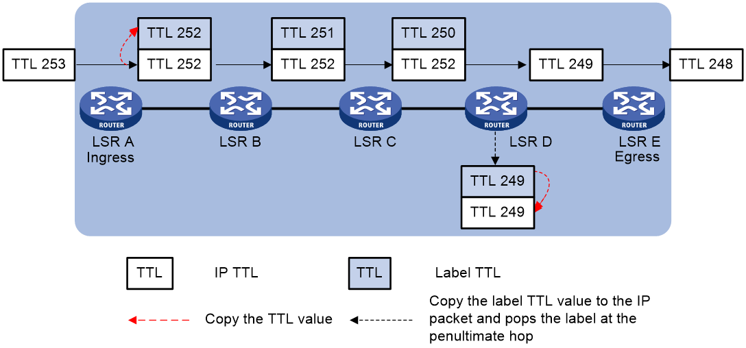
MPLS TTL propagation
When TTL propagation is enabled, the ingress node copies the TTL value of an IP packet to the TTL field of the label. Each LSR on the LSP decreases the label TTL value by 1. The LSR that pops the label copies the remaining label TTL value back to the IP TTL of the packet. The IP TTL value can reflect how many hops the packet has traversed in the MPLS network. The IP tracert facility can show the real path along which the packet has traveled.
Figure 10 TTL propagation is enabled
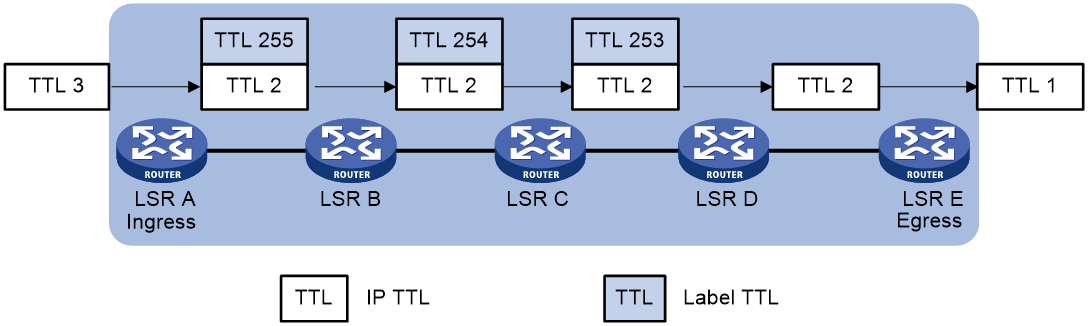
When TTL propagation is disabled, the ingress node sets the label TTL to 255. Each LSR on the LSP decreases the label TTL value by 1. The LSR that pops the label does not change the IP TTL value when popping the label. Therefore, the MPLS backbone nodes are invisible to user networks, and the IP tracert facility cannot show the real path in the MPLS network.
Figure 11 TTL propagation is disabled
SR-MPLS BE scenario
MPLS Segment Routing Best Effort (SR-MPLS BE) uses IGP to compute the optimal SRLSP by using the shortest path algorithm, and uses SIDs to instruct data forwarding. The SRLSP establishment and data forwarding are similar to the LDP LSP establishment and data forwarding. SR-MPLS BE does not use tunnel interfaces.
Figure 12 Establishing an SR-MPLS BE SRLSP tunnel
The creation of SR-MPLS BE's SRLSP tunnels is fully synchronized with the IGP calculation and convergence process. The tunnels are established simultaneously when the IGP routing is complete. As shown in Figure 12, the process of establishing SR-MPLS BE SRLSP tunnels is as follows:
1. Configure a Prefix SID on the loopback interface of Device C to generate forwarding entries and advertise them via IGP. After establishing an IGP neighbor relationship with Device B, Device C begins to advertise link state update packets (LSP). These LSP packets carry SR-related information and flood within the IGP network. Devices within the AS communicate through the IS-IS protocol, which advertises Device C's support for SR-MPLS capabilities in the LSP packets via the IS-IS Router Capability TLV-242 containing SR Capabilities Sub-TLV. This Sub-TLV contains the Prefix SID label information and Device C's SRGB information.
2. After Device B receives the LSP message advertised by Device C, it updates the local LSDB upon finding no existing route to 1.1.1.1/32. Device B also generates a local label forwarding entry based on the Prefix SID carried in the LSP toward the route prefix 1.1.1.1/32, which includes an egress label equal to Device C's SRGB plus Index, and an ingress label equal to Device B's SRGB plus Index. Device B then advertises the updated LSDB to other neighbors via SNP packets.
3. When Device A receives an SNP packet from Device B with new route prefix information, it requests a complete LSP from Device B. After receiving the LSP packet, Device A repeats the calculation process of Device B and updates its own LSDB to generate local label forwarding entries. This ensures that the LSDB of the entire IGP network is synchronized.
For more information about data forwarding in SR-MPLS BE, see "0Prefix SID-based packet forwarding within the same AS."
SR-MPLS TE scenario
MPLS Segment Routing Traffic Engineering (SR-MPLS TE) is TE tunnel technology that uses SR as the control protocol. SR-MPLS BE and SR-MPLS TE both need to establish SRLSPs, but the ways they establish SRLSPs are different. An SRLSP used by an SR-MPLS TE tunnel can be established manually through explicit path configuration. Or, it can be computed by the controller, which then deploys the label stack to the device for establishment of the SRLSP. The tunnel interface must be created on the ingress node of the SR-MPLS TE tunnel. The device encapsulates the label stack into the packets so as to control the forwarding path of the packets on the network.
SR-MPLS TE concepts
Label stack
A label stack is an ordered collection of labels that identifies a complete LSP. Each label in the stack identifies an egress interface, and the entire stack represents all links of the forwarding path LSP. During packet forwarding, the packet is forwarded using the label forwarding table corresponding to the top label in the stack. Once all labels are popped up from the stack, the packet completes its journey along the entire LSP and reaches the destination of the SR-MPLS TE tunnel.
Binding SID
As a tunnel interface, SR-MPLS TE, if assigned an Adjacency SID, can act as a unique identifier for the MPLS TE tunnel, using which traffic can be directed into the SR-MPLS TE tunnel. This Adjacency SID that identifies the SR-MPLS TE tunnel is known as the Binding SID.
The Binding SID can also implement label binding functionality. When the depth of the label stack exceeds the forwarding capacity of the device, a single label stack cannot carry the labels for the entire LSP. The controller must allocate multiple label stacks to the device, and at appropriate nodes, distribute the label stacks while assigning a special label that links these stacks together for segment-by-segment forwarding. This special label is known as the binding label, and the appropriate node is referred to as the binding node.
SR-MPLS tunnel establishment
Configuring a controller to calculate routes and create an SR-MPLS TE tunnel
Figure 13 Using a controller to deploy tunnel configuration and create a tunnel via NETCONF
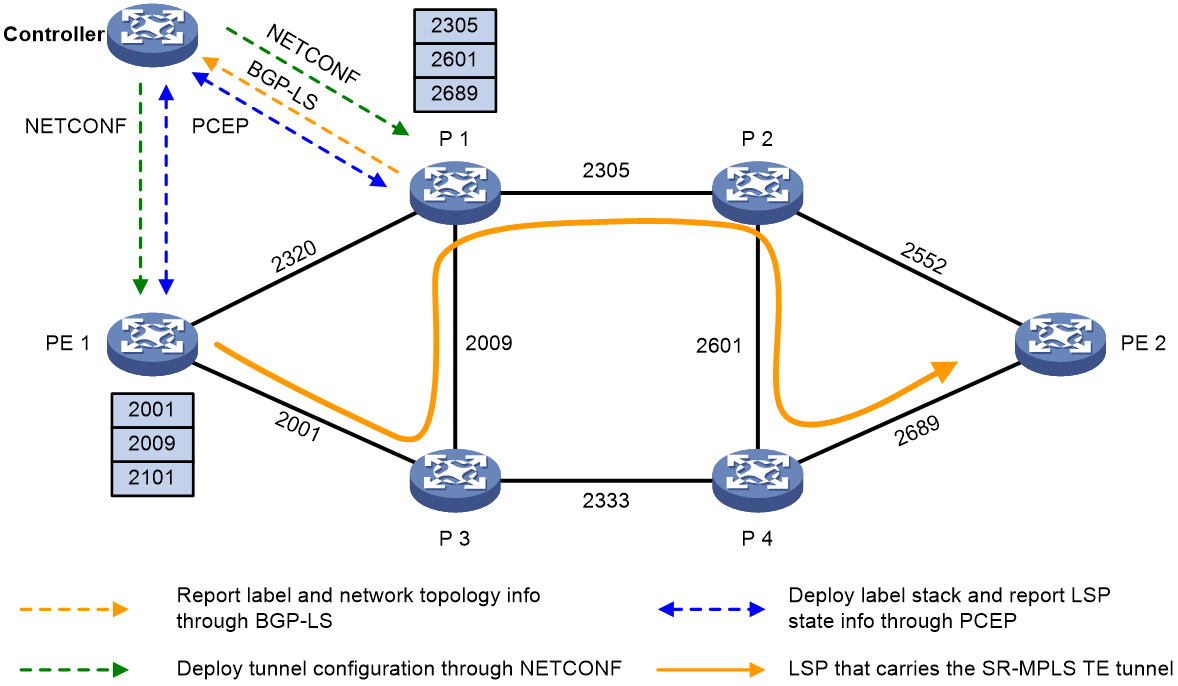
As shown in Figure 13, use the controller to establish an SR-MPLS TE tunnel as follows:
1. The controller calculates a path by using the PCE based on the tunnel constraint properties of MPLS TE. It integrates adjacent labels along the entire path, based on topology and adjacency, to form a label stack, which is the routing result.
When the label stack depth exceeds the device's supported stack depth, and a single stack cannot carry all adjacent labels, the controller must divide the entire path into multiple stacks to carry them.
As shown in Figure 13, the controller calculates the SR-MPLS TE tunnel path from PE 1 to P 3 to P 1 to P 2 to P 4 to PE 2, corresponding to two label stacks (2001, 2009, 2101) and (2305, 2601, 2689), where 2101 is the binding label and the others are adjacency labels.
2. The controller uses NETCONF and PCEP to send tunnel configuration and label stacks to the device, respectively.
As shown in Figure 13, the controller deploys the label stack as follows:
a. The controller deploys the label stack (2305, 2601, 2689) to the sticky node P1 and allocates a sticky label 2101 associated with this stack.
b. The controller sets 2101 as the bottom of the label stack on PE 1 and deploys the label stack (2001, 2009, 2101) to the ingress node PE 1.
3. The device establishes an SR-MPLS TE tunnel based on the tunnel configuration and label stack information deployed by the controller.
Configuring an explicit path to create an SR-MPLS TE tunnel
1. Plan and manually configure an explicit path by specifying the labels or IP addresses of the nodes the path traverses to reach the destination node.
2. Create an SR-MPLS TE tunnel interface and specify the signaling protocol as Segment Routing.
3. Reference an explicit path on the tunnel interface of the SR-MPLS TE tunnel to establish an SRLSP.
SR-MPLS TE data forwarding
The device performs label operations on packets based on the label stack corresponding to the LSP that carries the SR-MPLS TE tunnel and forwards them hop-by-hop by using the top label in the stack to transmit packets to the tunnel's destination address.
Figure 14 SR-MPLS TE data forwarding
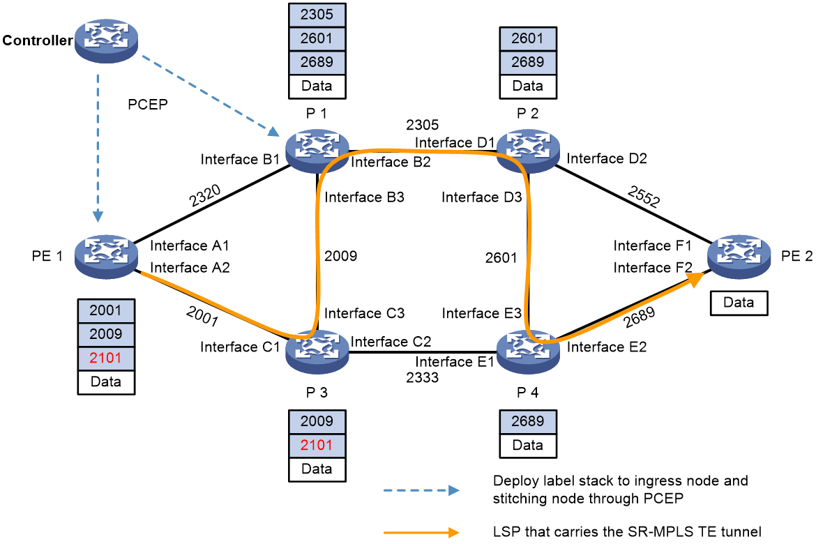
As shown in Figure 14, the controller calculates the SR-MPLS TE tunnel path as PE 1 -> P 3 -> P 1 -> P 2 -> P 4 -> PE 2, corresponding to two label stacks (2001, 2009, 2101) and (2305, 2601, 2689), which are deployed respectively to the ingress node PE 1 and the sticky node P 1. 2101 is the sticky label associated with the label stack (2305, 2601, 2689), and the others are adjacency labels. The SR-MPLS TE data forwarding process for this method is as follows:
1. The ingress node PE 1 adds a label stack (2001, 2009, 2101) to the packet. It then matches the top label 2001 against the label forwarding table and identifies the egress interface as Interface A2. Then, the node pops up label 2001. The packet, now carrying the label stack (2009, 2101), is forwarded through Interface A2 to the downstream node P 3.
2. After receiving the packet, the intermediate node P3 matches the top label 2009 with the label forwarding table and identifies the egress interface as Interface C3. It then pops up label 2009. The packet, carrying the label stack (2101), is forwarded to the downstream node P1 via Interface C3.
3. After node P1 receives the packet, it identifies the top label 2101 in the stack as the binding label by querying the adhesive label entry. It then switches the binding label 2101 for the associated label stack (2305, 2601, 2689). Using the new top label 2305, P1 finds the corresponding egress interface, Interface B2, by matching the label forwarding table and pops up label 2305. The packet, carrying the label stack (2601, 2689), is forwarded to downstream node P2 through Interface B2.
4. After receiving the packet, nodes P2 and P4 forward it in the same way as P3. Node P4 then removes the last label, 2689, and forwards the IP packet to node PE2.
5. When node PE 2 receives an IP packet without a label, it forwards the packet based on the destination IP address by looking up the IP routing table.
Traffic steering to an SR-MPLS tunnel
SR-MPLS tunnels include SR-MPLS BE tunnels and SR-MPLS TE tunnels.
After an SR-MPLS BE or SR-MPLS TE tunnel is established, traffic cannot be forwarded automatically through the tunnel. You must use one of the following methods to steer traffic to an SR-MPLS BE or SR-MPLS TE tunnel:
· Static route.
· Tunnel policy.
· PBR.
· Automatic route advertisement.
Static routing
The static route method is a simple, direct method for steering traffic to an SR-MPLS TE tunnel.
This method configures a static route destined for the destination address through the tunnel interface and allows the static route to recurse to LSP tunnels established by SR-MPLS TE.
Tunnel policy
VPN traffic tunneling uses LDP LSP tunnels by default. To direct VPN traffic to an SR-MPLS BE or SR-MPLS TE tunnel, you can apply a tunnel policy or tunnel selector to the VPN.
Based on the service requirements, you can configure one of the following types of tunnel policy to direct traffic of a VPN to an SR-MPLS BE or SR-MPLS TE tunnel:
· Tunnel binding—Bind a destination IP address to a tunnel in a tunnel policy. After the tunnel policy is applied to a VPN, the VPN traffic to the destination IP address will be forwarded by the bound tunnel.
· Preferred tunnel—Specify an SR-MPLS TE tunnel as a preferred tunnel in a tunnel policy. After the tunnel policy is applied to a VPN, the VPN traffic will be forwarded by the preferred tunnel. This method explicitly specifies a tunnel for a VPN, facilitating traffic planning.
· Load sharing—Specify the SR-MPLS BE or SR-MPLS TE tunnel types and the number of tunnels for load sharing in a tunnel policy. After the tunnel policy is applied to a VPN, the device selects the specified number of SR-MPLS BE or SR-MPLS TE tunnels in the specified order to forward the VPN traffic.
PBR
The policy-based routing (PBR) method defines a PBR policy to redirect traffic to an SR-MPLS TE tunnel. In the PBR policy, specify the output interface for packets that match an ACL as an SR-MPLS TE tunnel interface, and then applies the PBR policy to the incoming interface of packets.
The PBR method can match the packets to be forwarded by a tunnel interface by packet destination IP address, source IP address, and protocol type. Compared with the static route method, the PBR method is more flexible but its configuration is more complicated.
Automatic route advertisement
Automatic route advertisement distributes SR-MPLS TE tunnels to the IGP (OSPF or IS-IS), so the SR-MPLS TE tunnels can participate in IGP routing calculation.
Automatic route advertisement can be implemented by using the following methods:
· IGP shortcut—Also known as AutoRoute Announce. After IGP shortcut is enabled on the ingress node, it determines an SR-MPLS TE tunnel as a link that directly connects the tunnel ingress node (source node) and the egress node (endpoint node). However, it does not advertise the link to the network through IGP. Therefore, only the ingress node takes SR-MPLS TE tunnels into consideration for IGP route calculation, and other nodes do not do so.
· Forwarding adjacency—After forwarding adjacency is enabled on the ingress node, it considers the SR-MPLS TE tunnel as a link that directly connects the tunnel ingress node and the egress node. It also advertises the link to the network through an IGP. Therefore, every node in the network takes SR-MPLS TE tunnels into consideration for IGP route calculation.
The difference between IGP Shortcut and Forwarding Adjacency is as follows:
· After you enable the IGP Shortcut feature on the Ingress node of a tunnel, only that node will consider the SR-MPLS TE tunnel when calculating IGP routes. The IGP Shortcut feature does not advertise the SR-MPLS TE tunnel as a link via the IGP routing protocol. Therefore, other devices will not take the SR-MPLS TE tunnel into account when performing route calculations.
· After you enable the forwarding adjacency feature on the Ingress node of a tunnel, the Ingress node advertises the SR-MPLS TE tunnel as a link through the IGP routing protocol. Consequently, all devices in the IGP network consider the SR-MPLS TE tunnel when calculating routes.
Figure 15 IGP shortcut and forwarding adjacency
As shown in Figure 15, an SR-MPLS TE tunnel exists from Device D to Device C. IGP shortcut enables only the ingress node Device D to use the SR-MPLS TE tunnel in the IGP route calculation. Device A cannot use this tunnel to reach Device C. With forwarding adjacency enabled, Device A can learn this SR-MPLS TE tunnel and transfer traffic to Device C by forwarding the traffic to Device D.
IGP SR and LDP interworking
IGP SR and LDP interworking enables SR-MPLS networks that use an IGP for SID advertisement to communicate and cooperate with MPLS LDP networks.
IGP SR and LDP interworking supports the following modes:
· SR to LDP—Maps prefixes on an LDP network to SR-MPLS SIDs to forward traffic from an SR-MPLS network to an MPLS LDP network.
· LDP to SR—Uses an IGP protocol to advertise SIDs and associates SIDs with LDP labels to forward traffic from an MPLS LDP network to an SR-MPLS network.
· SR over LDP—Enables SR-MPLS networks to communicate through an LDP network.
· LDP over SR—Enables LDP networks to communicate through an SR-MPLS network.
IGP SR and LDP interworking mechanism
SR mappings
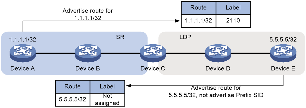
As shown in Figure 16, the label allocation methods for LDP networks and SR-MPLS networks are as follows:
· In an LDP network, devices allocate labels to prefix routes as soon as they learn them, without any special processing. For example, for prefix 1.1.1.1/32 in an SR network, once LDP network devices learn the route, they allocate a label to it.
· In an SR-MPLS network, a device must learn the prefix route and receive the prefix's SID before allocating a local SID for it. For example, although devices in the SR network can learn the prefix route for 5.5.5.5/32 from an LDP network, they will not allocate a local SID for it, because LDP devices cannot advertise the prefix SID for 5.5.5.5/32.
Figure 16 Label allocation for LDP and SR-MPLS networks
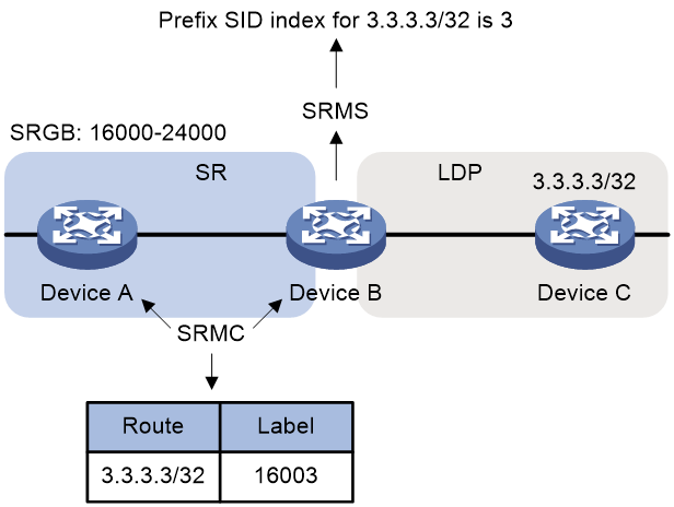
As shown in Figure 17, deploying SRMS and SRMC can resolve the issue where SR devices are unable to allocate SIDs for LDP network prefixes.
· Segment Routing Mapping Server (SRMS)—Advertises prefix-SID mappings on behalf of SR-incapable devices (LDP devices). You must configure prefix-SID mappings on the SRMS.
· Segment Routing Mapping Client (SRMC)—Receives prefix-SID mappings advertised by the SRMS and creates SR-MPLS label forwarding entries.
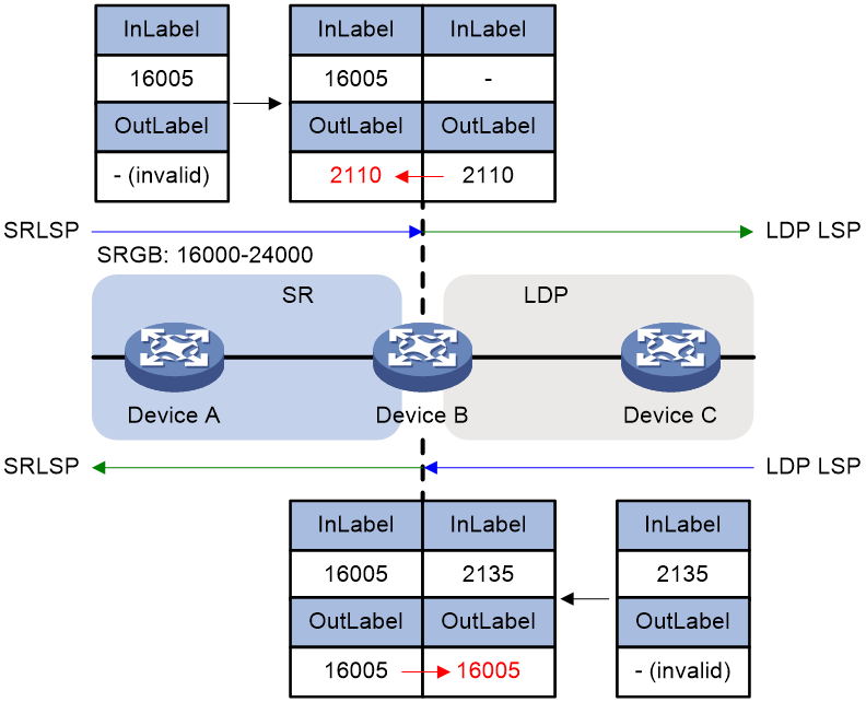
Label mapping
As shown in Figure 18, to enable interoperability between SR and LDP, devices connected to both SR and LDP networks must perform label mapping in the following two scenarios:
· Label connection from SR network to LDP network: Device B running LDP automatically allocates labels for host routes learned from node Device C. As an SRMS, Device B also advertises prefix SIDs for the host routes learned from Device C to Device A within the SR domain as an incoming label. If there is no valid SR-MPLS outgoing label to reach the LDP network device, the valid LDP outgoing label is used as the SR-MPLS outgoing label.
· Label connection from LDP network to SR network: When Device B, running SR, learns host routes from node Device A and the egress label prefix SID for SR, it advertises these host routes to Device C. Then, Device C triggers LDP to automatically allocate egress labels for the routes. On Device B, this egress label becomes the ingress label, while no valid egress label exists on Device B. If no valid LDP egress label to reach the SR network device is available, the valid SR-MPLS egress label is used as the LDP egress label.
SR to LDP
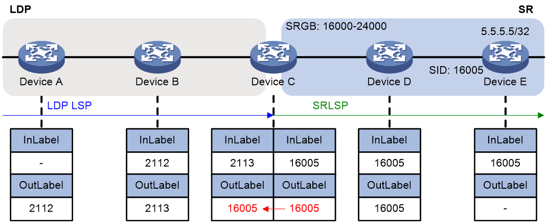
As shown in Figure 19, Devices C, D, and E run LDP protocol. Devices A, B, and C run the SR-MPLS. Deploy SRMS and SRMC on Devices A, B, and C to allocate prefix SIDs to devices within the LDP network, enabling data flow forwarding from the SR network to the LDP network.
Figure 19 SR to LDP packet forwarding
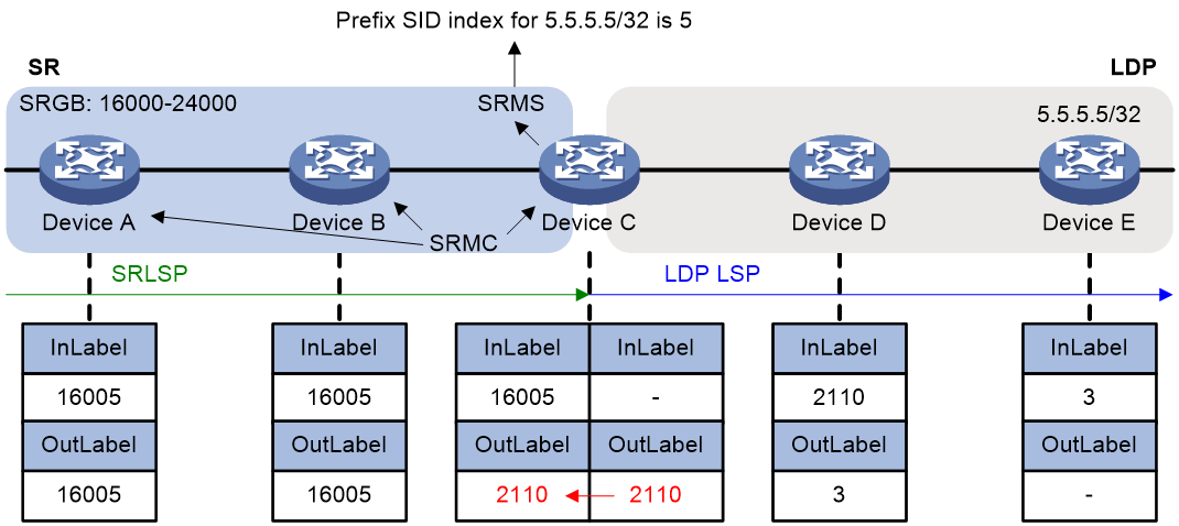
The process of associating SR-MPLS labels with LDP labels is as follows:
1. Devices C, D, and E allocate labels for the destination address 5.5.5.5/32, creating an LDP label forwarding entry.
2. Device C, acting as an SRMS, allocates prefix SID index value 5 for destination address 5.5.5.5/32 and advertises the prefix SID index value to Device A and Device B. As an SRMC, Device C also allocates SID 16005 for destination address 5.5.5.5/32, creating a corresponding SR-MPLS label forwarding entry with an invalid outgoing label. Device C replaces the invalid SR-MPLS outgoing label for traffic reaching Device E with a valid LDP outgoing label 2110.
3. Device A and Device B, acting as SRMCs, receive advertisement information and allocate SID 16005 to the destination address 5.5.5.5/32, creating their own SR-MPLS label forwarding entries.
LDP to SR
As shown in Figure 20, Device A, Device B, and Device C run LDP. Device C, Device D, and Device E run SR-MPLS. To achieve traffic forwarding from LDP to SR, you do not need to deploy SRMS and SRMC. LDP labels can automatically associate with SR labels, allowing direct forwarding of packets based on the forwarding table.
Figure 20 LDP to SR packet forwarding
The process of associating SR-MPLS labels with LDP labels is as follows:
1. Device E assigns the prefix type SID index value 5 to 5.5.5.5/32 and advertises this index value along with the local SRGB via the IGP protocol. Additionally, Device E allocates SID 16005 to the destination address 5.5.5.5/32, creating the corresponding SR-MPLS label forwarding entry.
2. After Device C and Device D receive the advertisement, they allocate SID 16005 for the destination address 5.5.5.5/32, creating the corresponding SR-MPLS label forwarding entry.
3. Device A, Device B, and Device C allocate labels for the destination address 5.5.5.5/32, creating an LDP label forwarding entry.
4. Device C replaces the invalid LDP outgoing label for reaching Device E with the valid SR-MPLS outgoing label 16005.
SR over LDP
As shown in Figure 21, Device C, Device D, and Device E run LDP. Device A, Device B, Device C, Device E, Device F, and Device G run SR-MPLS. Devices within an SR network can advertise prefix SIDs across an LDP network to the other end of the SR network via the IGP protocol. You do not need to deploy SRMS and SRMC within the SR network.
Figure 21 SR over LDP network interoperability
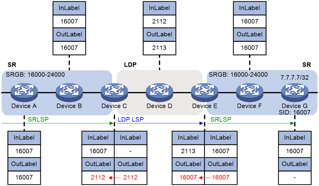
The process of associating SR-MPLS labels with LDP labels is as follows:
1. Device G allocates a prefix SID index value of 7 for 7.7.7.7/32 and advertises the index value along with the local SRGB via the IGP protocol. Simultaneously, Device G assigns SID 16007 to the destination address 7.7.7.7/32, creating the corresponding SR-MPLS label forwarding entry.
2. After receiving the advertisement, Devices A, B, C, E, and F allocate SID 16007 for the destination address 7.7.7.7/32, creating the corresponding SR-MPLS label forwarding entry.
3. Devices C, D, and E allocate labels for the destination address 5.5.5.5/32, creating an LDP label forwarding entry.
4. Device C replaces the invalid SR-MPLS outgoing label for reaching Device G with the valid LDP outgoing label 2112.
5. Device E replaces the invalid LDP outgoing label for reaching Device G with the valid SR-MPLS outgoing label 16007.
LDP over SR
Devices A, B, C, E, F, and G run LDP. Devices C, D, and E run SR-MPLS. In an LDP over SR networking environment, deploy SRMS and SRMC in the SR network to establish label forwarding entries for reaching LDP devices.
Figure 22 LDP over SR network interoperability
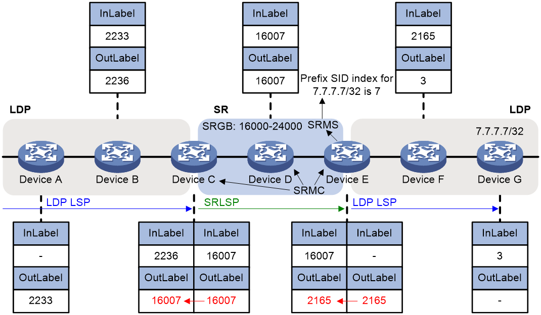
The process of associating SR-MPLS labels with LDP labels is as follows:
1. Devices A, B, C, E, F, and G allocate labels for the destination address 7.7.7.7/32 to create LDP label forwarding entries.
2. Device E, acting as an SRMS, allocates prefix type SID index value 7 for Device G's 7.7.7.7/32 and advertises the prefix SID index value to Device C and Device D. As an SRMC, Device E also allocates SID 16007 for the destination address 7.7.7.7/32, creating a corresponding SR-MPLS label forwarding entry with an invalid outgoing label. Device E replaces the invalid SR-MPLS outgoing label for traffic to Device G with a valid LDP outgoing label 2165.
3. Device C and Device D, acting as SRMCs, receive advertisement information and allocate SID 16007 for the destination address 7.7.7.7/32, creating their respective SR-MPLS label forwarding entries.
4. Device C replaces the invalid LDP outgoing label for reaching Device G with a valid SR-MPLS outgoing label 16007.
Interoperability between BGP SR and non-SR label forwarding networks
In inter-AS networking scenarios, BGP SR enables interoperability with non-SR label forwarding networks that use BGP for label allocation. In non-SR label forwarding networks, the outer tunneling protocol for BGP labels (the public network tunneling protocol) can be RSVP-TE, LDP, or GRE. The following describes the interoperability mechanism by using the LDP protocol as an example.
When both an SR-MPLS network that advertises SIDs by using the BGP protocol and a public network tunnel based on LDP exist, to achieve interconnectivity between the SR and LDP networks, edge devices of the LDP network must support SR. These devices establish associations between routing prefix addresses, SIDs, and MPLS labels for BGP neighbors within the LDP network that do not support SR. Therefore, the following two roles are defined:
· SRMS—In an SR network, it replaces LDP devices that do not support SR-MPLS by advertising SIDs. Configure the prefix address and SID mappings on SRMS and advertise them to SRMC.
· SRMC—Receive mappings of prefix addresses and SIDs advertised by SRMS in an SR network to create an SR-MPLS label forwarding table.
BGP SR and LDP interoperability uses the following procedure:
· SR to LDP—Maps the prefix addresses of the LDP network to the SR network's SIDs via BGP to enable data traffic from the SR network to the LDP network.
· LDP to SR—Advertises the SID via BGP and associates it with the labels requested by BGP to enable data flow forwarding from an LDP network to an SR network.
SR to LDP
To implement SR to LDP by using the BGP protocol, a device can only allocate SIDs to nodes in the LDP network that do not support SR based on locally configured prefix addresses and SID mappings. Therefore, nodes with both SR-MPLS and LDP functionalities enabled must act as both an SRMS and SRMC.
As shown in Figure 23, Devices B, C, and D run LDP. Devices A and B are enabled with BGP SR-MPLS. The label distribution process is as follows:
1. Device C and Device D distribute labels 20 and 3 (implicit-null label) respectively via LDP for the destination address 3.3.3.3/32, creating LDP label forwarding entries on Devices B, C, and D.
2. Device D advertises a BGP route 3.3.3.3/32 with label 1274 to Device B, which BGP requested, with Device D as the next hop.
3. Device B, acting as an SRMS, allocates index value 201 to the loopback address 3.3.3.3/32 on Device D.
4. Device B acts as an SRMC and generates an SR-MPLS label forwarding table based on locally configured prefix addresses and SID mappings. Device B establishes mappings between SRLSP and BGP LSP, meaning that for traffic to 3.3.3.3/32 on Device B, the label forwarding table entry has an incoming SR-MPLS label of 16201 and an outgoing label of 1274 assigned by BGP.
5. Device B advertises the prefix SID of 3.3.3.3/32 to Device A via BGP packets. Device A then creates the corresponding SR-MPLS label forwarding table based on the received BGP packets.
Figure 23 SR to LDP packet forwarding
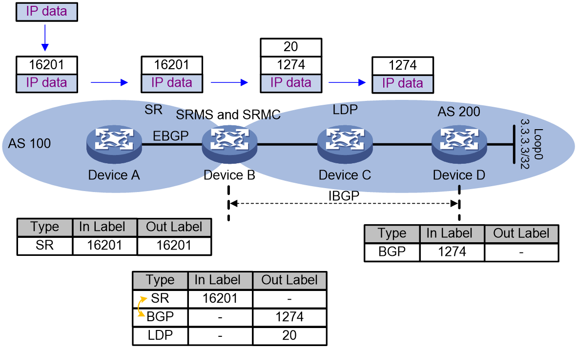
If Device A uses an SRLSP to send a packet to Device D, the packet is forwarded as follows:
1. Ingress node Device A adds label 16201 to the packet and then sends the packet to transit node Device B.
2. When transit node Device B receives the packet, it searches for a label forwarding entry that matches incoming label 16201. Because the entry does not have an outgoing label, Device B searches for a valid LDP outgoing label for destination address 3.3.3.3/32. Then, Device B adds the LDP label (20) to the packet as the SR outgoing label and forwards the packet to the next hop (Device C).
3. When transit node Device C receives the packet, it searches for an LDP label forwarding entry for incoming label 20. Then, it removes the label from the packet and forwards the packet to egress node Device D.
4. The egress node forwards the packet by IP address.
LDP to SR
As shown in Figure 24, Device C and Device D are running SR-MPLS, and Device A, Device B, and Device C are running LDP. Each device running LDP assigns a label to destination address 3.3.3.3/32 and then installs an LDP label forwarding entry.
1. The following steps establish an association between the SR-MPLS label and the LDP label:
2. After you assign SID index value 201 to the IP address of loopback interface 0 on Device D (3.3.3.3/32), Device D sends an IGP protocol packet to advertise the index value and the local SRGB.
3. After receiving the packet, Device C creates an SR-MPLS label forwarding entry.
4. Device C requests label 1280 for 3.3.3.3/32 and advertises the route 3.3.3.3/32 with label 1280 to its IBGP neighbor Device A.
5. The SR-MPLS label and the LDP label are associated on Device C.
Figure 24 LDP to SR packet forwarding
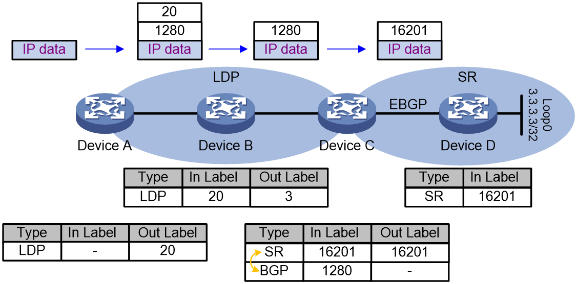
A packet from Device A to Device D is forwarded as follows:
1. Device A encapsulates the packet with label 1280, with Device C as the next hop. Device A needs to reach Device C via an LDP LSP, so it encapsulates the packet with an outer label 20. Device A then forwards the encapsulated packet to Device B.
2. Device B searches for an LDP label forwarding entry, uses 3 as the outgoing label, and forwards the packet to the next hop (Device C).
3. Upon receiving the packet carrying label 1280, Device C replaces the outgoing label with SR-MPLS label 16201 based on the mapping between the SR-MPLS label and BGP label 1280 and sends the packet to the egress node, Device D.
4. Egress node Device D deletes label 16201 from the packet and forwards the packet by IP address.
SR-MPLS TE Policy
Segment Routing (SR) policies enable the device to flexibly steer traffic through an SR network. SR-MPLS TE policies apply to scenarios where multiple paths exist between a source node and a destination node on an SR network.
Basic concepts of SR-MPLS TE Policy
An SR-MPLS TE policy is identified by the following items:
· Headend—Source node. The source node imports packets into the SR-MPLS TE Policy, which then guides the packet to be forwarded along the selected path.
· Color—Color attribute for the forwarding path. You can use the color attribute to distinguish an SR-MPLS TE policy from other SR-MPLS TE policies that are configured for the same source and destination nodes.
· Endpoint—IP address of the destination node.
An SR-MPLS TE Policy contains a BSID and multiple candidate paths with different priorities, each including one or more forwarding paths identified by a Segment List (SID list).
· BSID
The Binding SID is the interface through which the SR-MPLS TE Policy provides network services. Encapsulating the SID in a packet directs the traffic to that SR-MPLS TE Policy.
· Candidate path
A candidate path is a forwarding path that an SR-MPLS TE policy can use to forward packets.
An SR-MPLS TE policy can have multiple candidate paths. Two SR-MPLS TE policies cannot share the same candidate path.
· Segment list
A segment list is a list of SIDs that indicates a packet forwarding subpath. Each SID identifies the segment for forwarding packets to the next hop along the subpath. A candidate path can have a single SID list or multiple SID lists that use different weight values.
The following concepts are also involved in SR-MPLS TE Policy:
Preference
Candidate paths are uniquely identified by their preference values. An SR-MPLS TE policy chooses a candidate path from all its candidate paths based on the preference values.
Weight
A SID list can have a weight value. After an SR-MPLS TE policy chooses a candidate path with multiple SID lists, the traffic will be load shared among the subpaths based on weight values.
SR-MPLS TE policy tunnel
An SR-MPLS TE policy tunnel is a virtual point-to-point connection between the node deployed with the SR-MPLS TE policy and the destination node of the SR-MPLS TE policy. The tunnel is automatically created upon SR-MPLS TE policy creation. SR-MPLS TE policy tunnels use SRLSPs.
SR-MPLS TE policy group
An SR-MPLS TE policy group is a collection of SR-MPLS TE policies. You can add SR-MPLS TE policies to an SR-MPLS TE policy group to implement SR-MPLS TE policy based forwarding according to DSCP values of packets.
SR-MPLS TE policy validity
The following describes the rules for identifying the validity of a SR-MPLS TE policy:
Figure 25 SR-MPLS TE policy validity
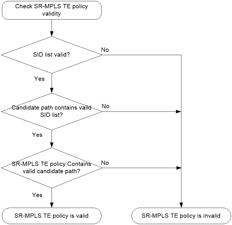
A SID list is valid if none of the following conditions is met:
· The SID list is empty.
· The weight of the SID list is 0.
· An SR node cannot find the outgoing interface or next hop address based on the SID at the top of the SID list stack.
SR-MPLS TE policy routing procedure
The following describes how the device chooses and uses an SR-MPLS TE policy to route a packet:
1. Upon receiving a packet whose stack top label is a BSID, the device identifies the valid SR-MPLS TE policies based on the BSID.
2. If multiple valid SR-MPLS TE policies are available, the device chooses the SR-MPLS TE policy that was first bound to the BSID.
3. If the chosen SR-MPLS TE policy has multiple candidate paths, the device chooses the candidate path with the greatest preference value.
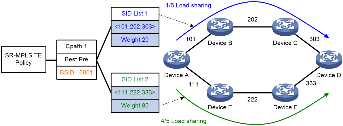
4. If the chosen candidate path has multiple SID lists, the traffic will be load shared based on the weight values among the subpaths identified by the SID lists. The load of SID list x is equal to Weight x/(Weight 1 + Weight 2 + … + Weight n).
For example, Device A in Figure 1 first chooses a valid SR-MPLS TE policy by BSID. Then, the device chooses a candidate path by preference. The candidate path has two valid SID lists: SID list 1 and SID list 2. The weight value of SID list 1 is 20 and the weight value of SID list 2 is 80. One fifth of the traffic will be forwarded through the subpath identified by SID list 1. Four fifth of the traffic will be forwarded through the subpath identified by SID list 2.
Figure 26 SR-MPLS TE policy routing diagram
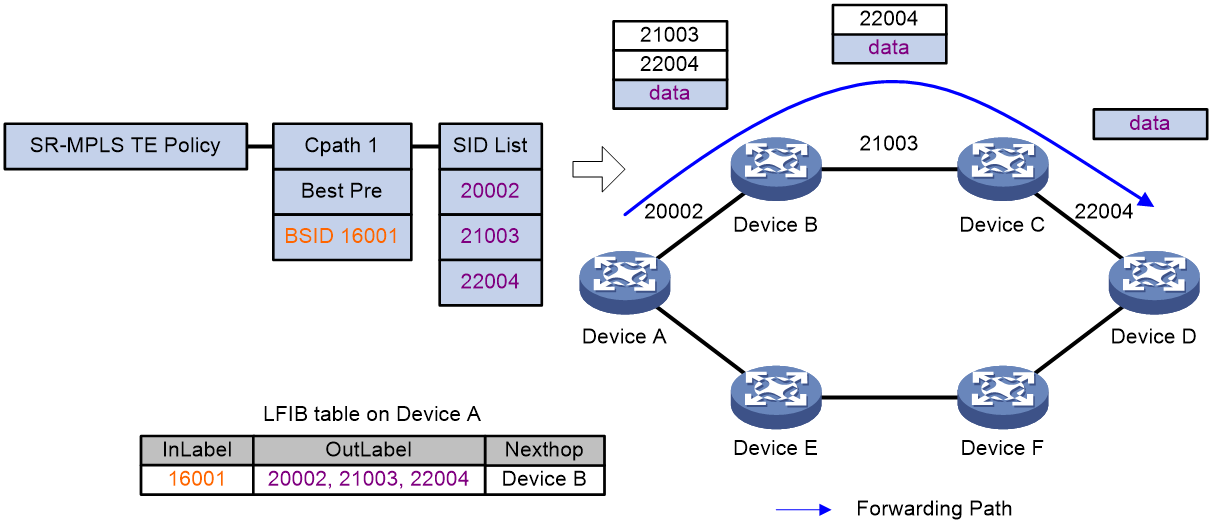
SR-MPLS TE policy traffic forwarding
As shown in Figure 27, the SR-MPLS TE policy forwarding procedure is as follows:
1. After Device A receives a packet with the stack top label 16001, it searches its LFIB and determines that the label is a BSID. Then, Device A obtains the outgoing label stack and next hop (Device B), pops the BSID, pushes SID list {20002, 21003, 22004}, and forwards the packet to Device B. 20002 is the SID of the segment for a packet to travel from Device A to Device B. 21003 is the SID of the segment for a packet to travel from Device B to Device C. 22004 is the SID of the segment for a packet to travel from Device C to Device D.
2. After Device B receives the packet, it searches its LFIB by the incoming label and determines that the next hop is Device C. Then, Device B forwards the packet to Device C.
3. After Device C receives the packet, it searches its LFIB by the incoming label and determines that the next hop is Device D. Then, Device C forwards the packet to Device D.
4. After Device D receives the packet, it identifies whether the packet is carrying a label. If yes, Device D searches its LFIB to forward the packet. If not, Device D searches its IP FIB to forward the packet.
Figure 27 SR-MPLS TE policy forwarding diagram
Traffic steering to an SR-MPLS TE policy
You can steer traffic to an SR-MPLS TE policy for further forwarding based on the following criteria:
· BSID—Upon receiving a packet whose stack top label is a BSID, the device chooses an SR-MPLS TE policy based on the BSID to forward the packet.
· Color—The device searches for an SR-MPLS TE policy with the color value and endpoint that match the color extended community attribute and next hop of a BGP route. If a matching SR-MPLS TE policy is found, the device recurses the BGP route to that SR-MPLS TE policy. Then, packets matching the BGP route will be steered to the SR-MPLS TE policy for further forwarding.
· Tunnel policy—In an MPLS L3VPN or EVPN L3VPN, configure a tunnel policy that uses an SR-MPLS TE policy as the public tunnel to carry the VPN packets.
· DSCP value—Create color-to-DSCP mappings for an SR-MPLS TE policy group, and create a tunnel policy that binds a destination IP address to the SR-MPLS TE policy group. Upon receiving a packet with the specified destination IP address, the device searches for the SR-MPLS TE policy containing the color value mapped to the DSCP value of the packet. The device will use the SR-MPLS TE policy to forward the packet.
· Static route—Associate a static route with an SR-MPLS TE policy so that packets matching the static route will be steered to the SR-MPLS TE policy for forwarding.
· QoS policy—Redirect traffic to an SR-MPLS TE policy through a QoS policy. The device uses the SR-MPLS TE policy to forward the packets that match the traffic classes of the QoS policy.
· Flowspec—Redirect traffic to an SR-MPLS TE policy through a Flowspec rule. The device uses the SR-MPLS TE policy to forward the packets that match the Flowspec rule.
SR-MPLS TE policy hot standby
If an SR-MPLS TE policy has multiple valid candidate paths, the device chooses the candidate path with the greatest preference value. If the chosen path fails, the SR-MPLS TE policy must select another candidate path. During path reselection, packet loss might occur to affect service continuity.
The SR-TE hot standby feature can address this issue. This feature takes the candidate path with the greatest preference value as the primary path and that with the second greatest preference value as the standby path. As shown in Figure 28, when the forwarding paths corresponding to all SID lists of the primary path fails, the standby path immediately takes over to minimize service interruption.
Figure 28 Figure 5 SR-MPLS TE policy hot standby
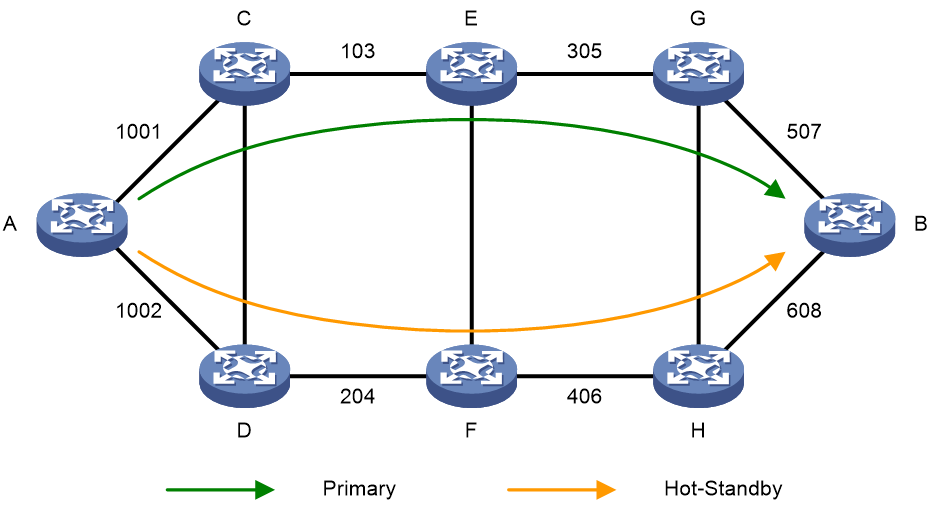
You can configure both the hot standby and SBFD features for an SR-MPLS TE policy. Use SBFD to detect the availability of the primary and standby paths specified for hot standby. If all SID lists of the primary path become unavailable, the standby path takes over and a path recalculation is performed. The standby path becomes the new primary path, and a new standby path is selected. If both the primary and standby paths fail, the SR-MPLS TE policy will calculate new primary and standby paths.
MP-BGP extension for SR-MPLS TE policy-based routing
To support SR-MPLS TE policies, MP-BGP increases the following definitions:
· BGP IPv4 SR policy address family.
· BGP IPv4 SR policy routes, which are also called SR-MPLS TE policy NLRI.
BGP IPv4 SR policy route information carries SR-MPLS TE policy settings, including the BSIDs, color values, endpoints, preference values, and weight values. After the device advertises BGP IPv4 SR policy routes to a peer, the peer can also use SR-MPLS TE policies to steer traffic.
The device supports the color extended community attribute. Upon receiving a packet that matches a route with the color extended community attribute, the device searches for an SR-MPLS TE policy that has the same color value as the route. If an SR-MPLS TE policy is found, the device forwards the packet based on the SR-MPLS TE policy. If not, the device uses the optimal route to forward the packet.
The color extended community attribute is in the format of 2-bit Color-Only flag:32-bit user-defined color value, for example, 10:3.
SBFD for SR
Seamless BFD (SBFD) is a unidirectional failure detection mechanism that simplifies the BFD state machine and shortens the session negotiation time to provide shorter detection time than BFD. An SBFD session has only UP and DOWN states. SBFD is used in scenarios where only one end of a link requires failure detection.
An SBFD session involves the following roles:
· Initiator—Initiates and maintains an SBFD session by periodically sends SBFD control packets or SBFD echo packets.
· Reflector—Listens for incoming SBFD control packets and replies with response SBFD control packets. The reflector does not maintain the SBFD session state.
The SBFD detection mechanism in control packet mode is as follows:
1. The initiator periodically sends SBFD control packets to the reflector.
2. After receiving an SBFD control packet, the reflector checks whether the remote discriminator carried in the packet is the same as the locally configured one. If they are the same, the reflector sends a response SBFD control packet to the initiator. If they are different, the reflector drops the SBFD control packet.
3. If the initiator receives the response SBFD control packet before the detection time expires, it considers the link available. Otherwise, it considers the link unavailable
Collaboration between SR-BE LSP and SBFD
In the SR-BE LSP scenario, SBFD can quickly detect faults on the primary SR-BE path.
Figure 29 Using SBFD to detect the primary path fault in SR-BE
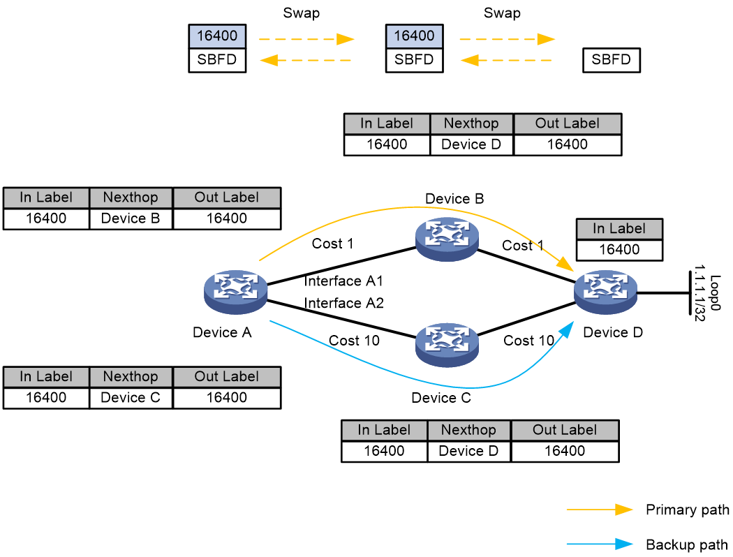
As shown in Figure 30, the SRGB range for all devices is from 16000 to 17000. The process for SBFD detection of the SR-BE path is as follows:
1. The source node, Device A, sends out SBFD packets, which recurse to the SR-BE tunnel and are encapsulated with the SID for the next-hop node. Based on the IGP SPF routing result, the packets are preferentially forwarded along the primary SR-BE path. At the intermediate node B, label swapping occurs, and forwarding continues to the egress node, Device D.
2. Upon receiving the SBFD packet, the egress node, Device D, looks up the IP routing table to send a response packet back via the shortest path.
3. If the source node, Device A, receives the SBFD response packet, it determines that the primary SR-BE path is functioning correctly. If it does not receive the packet, it determines that there is a fault in the primary SR-BE path. If an alternative path for the SR-BE LSP exists, SBFD triggers a switch from the primary to the backup path.
Collaboration between SR-MPLS TE and SBFD
In the SR-MPLS TE scenario, SBFD can quickly detect faults in SR-MPLS TE tunnels.
Figure 30 Using SBFD to detect faults in SR-MPLS TE paths
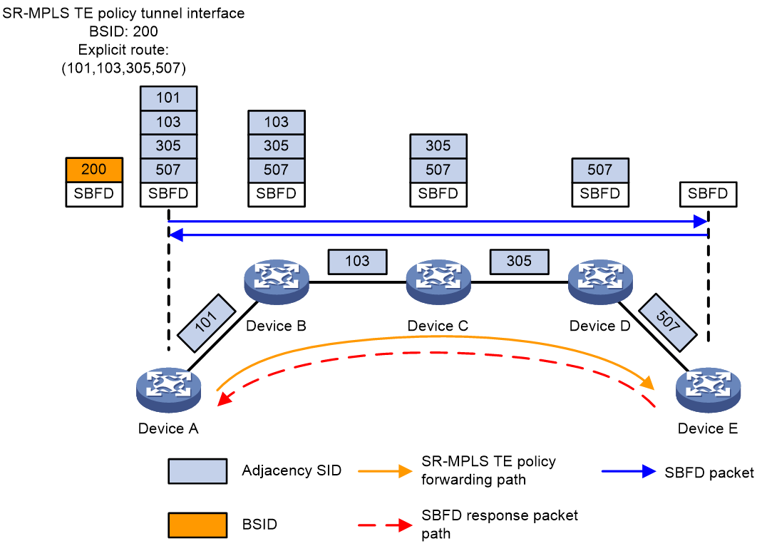
SBFD detection for SR-MPLS TE paths proceeds as follows:
1. The source node Device A sends an SBFD packet with the SID lists of the primary and backup candidate paths of the SR-MPLS TE policy encapsulated.
2. After receiving the SBFD packet, egress node Device E transmits a response by looking up the IP routing table for the shortest path.
3. If the source node, Device A, receives the SBFD response packet, it determines that the primary path is functioning correctly. If it does not receive the packet, it determines that there is a fault in the primary path. If a hot-backup path for the SR-MPLS TE exists, SBFD triggers a switch from the primary to the backup path.
Collaboration between SR-MPLS TE Policy and SBFD
In the SR-MPLS TE Policy scenario, SBFD can quickly detect faults that occur on SR-MPLS TE Policy paths. Compared to SR-MPLS TE scenarios, SBFD can detect explicit paths represented by multiple SID lists.
By default, SBFD only monitors the SID list in the candidate path with the highest priority in the SR-MPLS TE Policy.
Figure 31 Collaboration between SR-MPLS TE Policy and SBFD
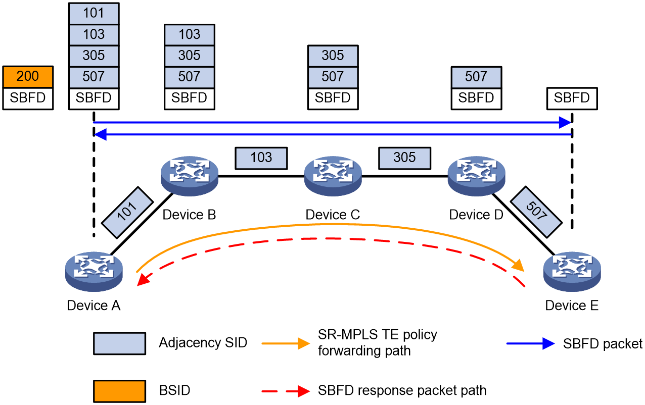
As shown in Figure 31, after the source node, Device A, is enabled with collaboration between SR-MPLS TE Policy and SBFD, it uses the Endpoint address as the remote descriptor for SBFD. When there are multiple SID lists within the highest-priority candidate path of the SR-MPLS TE Policy, multiple SBFD sessions are established to monitor the forwarding path corresponding to each SID list, with all SBFD sessions sharing the same remote descriptor. If all Segment Lists under a candidate path fail, SBFD triggers a candidate path switch.
The process to detect an SR-MPLS TE Policy path by using SBFD is as follows:
1. The source node Device A sends an SBFD packet with the SID list of the SR-MPLS TE policy encapsulated.
2. After receiving the SBFD packet, egress node Device E transmits a response by looking up the IP routing table for the shortest path.
3. If the source node, Device A, receives the SBFD response packet, it determines that the forwarding path corresponding to the SID list is functioning correctly. If it does not receive the packet, it determines that there is a fault in the forwarding path. If all forwarding paths corresponding to the SID lists in the same candidate path fail, SBFD triggers a switch from the primary to the backup path.
TI-LFA FRR
Topology-Independent Loop-Free Alternate Fast Re-Route (TI-LFA FRR) provides link and node protection. When a link or node fails, TI-LFA FRR switches the traffic to the backup path to ensure continuous data forwarding.
TI-LFA FRR advantages
SR-based TI-LFA FRR has the following advantages:
· It satisfies the basic requirements for IP FRR fast convergence.
· Traffic protection is not affected by the network environment.
· The algorithm is not too complicated.
· It uses the converged route as the backup path. All devices have finished route convergence before the forward process begins.
TI-LFA FRR concepts
· P space—Use the source node of the protected link as the root to establish a shortest path tree. All nodes that are reachable from the source node without passing the protected link form the P space. Nodes in the P space are called P nodes.
· Extended P space—Use the source node of the protected link and its neighbors as the roots to establish shortest path trees. All nodes that are reachable from the source node or one of its neighbors without passing the protected link form the extended P space. The P space is a subset of the extended P space.
· Q space—Use the destination node of the protected link as the root to establish a reverse shortest path tree. All nodes that are reachable from the root node without passing the protected link form the Q space. Nodes in the Q space are called Q nodes.
TI-LFA FRR protection
TI-LFA traffic protection includes the following two types:
· Link protection—Use this type of traffic protection when the traffic passing through a specific link is to be protected.
· Node protection—Use this type of traffic protection when the traffic passing through a specific device is to be protected.
Node protection takes precedence over link protection.
TI-LFA FRR path calculation
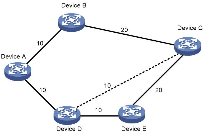
As shown in Figure 32, PE 1 is the source node. P 1 is the faulty node. PE 2 is the destination node. The numbers on links represent the link costs. A data flow traverses PE 1, P 1, and PE 2. To protect data against P 1 failure, TI-LFA FRR calculates the extended P space, Q space, shortest path tree converged after P 1 fails, repair list, and backup output interface, and creates the backup forwarding entry.
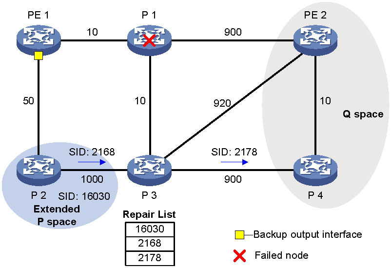
TI-LFA FRR calculates the backup path by using the following steps:
1. Calculates the extended P space: P 2.
2. Calculates the Q space: PE 2 and P 4.
3. Calculates the shortest path tree converged after P 1 fails: PE 1 --> P 2 --> P 4 --> PE 2.
4. Calculates the repair list: Node label of P 2 (16030), adjacency SID of P 2 to P 3 (2168), and adjacency SID of P 3 to P 4 (2178).
5. Calculates the backup output interface, that is, the output interface to the next hop after the link from PE 1 to P 1 fails.
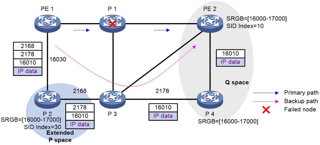
TI-LFA FRR forwarding process
After TI-LFA FRR finishes backup path calculation, traffic will be switched to the backup path in response to a primary path failure.
As shown in Figure 33, P 2 is a P node and P 4 is a Q node. When the next hop on the primary path (P 1) fails, TI-LFA FRR switches the traffic to the backup path. The following are the detailed steps:
1. PE 1 encapsulates a label stack to a packet according to the repair list. The labels, from the outmost to inmost, are as follows:
¡ Node label of P node P2 (16030), which equals the SRGB base value of PE 1 (nexthop of the P node) plus the SID index value of P 2.
¡ Adjacency SIDs from P node P2 to Q node P 4, which are 2168 and 2178.
¡ The destination's node label 16010, which equals the SRGB base value of Q node P 4 plus the SID index value of destination node PE 2.
2. P2 receives the packet, searches for a label forwarding entry based on the outmost label, pops label 2168, and forwards the packet to P 3.
3. P3 receives the packet, searches for a label forwarding entry based on the outmost label, pops label 2178, and forwards the packet to P 4.
4. P4 receives the packet, and searches for a label forwarding entry based on the outmost label. Because the outgoing label is 16010 and the next hop is PE 2, P 4 encapsulates 16010 as the outmost label and forwards the packet to PE 2.
Figure 33 Data forwarding over the TI-LFA FRR backup path
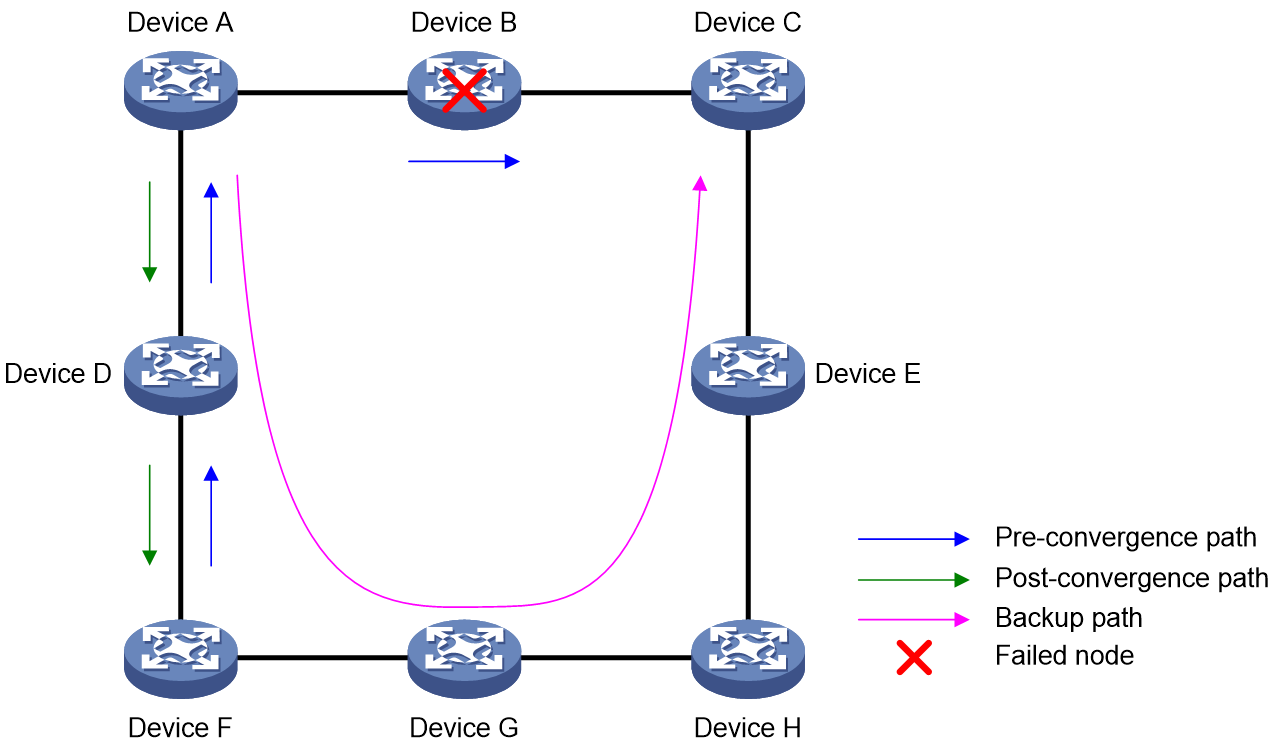
Microloop avoidance after a network failure
As shown in Figure 34, when Device B fails, traffic to Device C will be switched to the backup path calculated by TI-LFA. After Device A finishes route convergence, traffic will be switched to the post-convergence path. If Device D and Device F have not finished route convergence and still forward traffic along the pre-convergence path, a loop is formed between Device A and Device F. The loop exists until Device D and Device F finish route convergence.
FRR microloop avoidance and SR microloop avoidance can resolve this issue. After you configure TI-LFA, Device A first switches traffic to the backup path calculated by TI-LFA when Device B fails. Then, Device A waits for Device D and Device F to finish route convergence before starting route convergence. After Device A also finishes route convergence, Device A switches the traffic to the converged route.
Figure 34 Diagram for microloop avoidance after a network failure
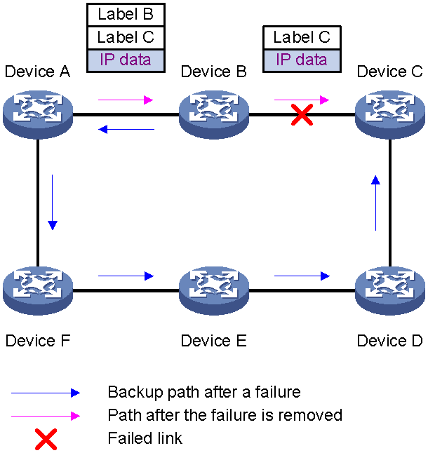
Microloop avoidance after a failure recovery
As shown in Figure 35, before the link between Device B and Device C recovers, traffic traverses along the backup path. After the link recovers, Device A will forward the traffic to Device B if Device A finishes route convergence before Device B. Before Device B also finishes route convergence, Device B still forwards the traffic along the backup path. A loop is formed between Device A and Device B.
SR microloop avoidance can resolve this issue. After the link recovers, SR microloop avoidance automatically calculates the optimal path from Device A to Device C and forwards traffic along the path. To forward a packet along the newly calculated path, Device A adds, for example, the adjacency SID from Device B to Device C to the packet and then sends the packet to Device B. Then, Device B forwards the packet to Device C based on the path information.
When the microloop avoidance RIB-update-delay timer expires, Device B should have finished route convergence. Device A does not add path information to packets anymore, and it forwards packets to Device C as usual.
Figure 35 Figure 20 Diagram for microloop avoidance after a failure recovery
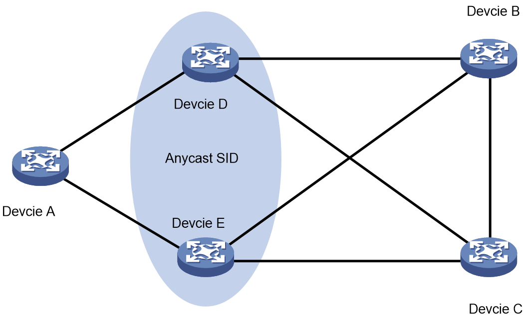
Anycast SR
To enhance network reliability, several SR nodes can be grouped together, with these SR nodes advertising the same address and the same SID within the network. When you configure a prefix SID, you can set the n-flag-clear parameter to set the prefix SID flag to 0, indicating that the prefix SID represents a group of SR nodes, known as Anycast SR, and this prefix SID is an Anycast SID.
Typically, the FRR algorithm can only use SPF to determine backup next-hops from a single source publishing a route, and it does not support scenarios with multiple sources advertising the same route. In scenarios where multiple sources advertise the same route, to calculate the backup next-hop for a prefix SID, you can deploy Anycast SR to allow multiple route advertising nodes to be treated as a single node for calculation purposes.
As shown in Figure 36, you can assign Device D and Device E to the same group. Assume that the optimal path from Device A to Device B passes through Device D. The path that passes Device E will act as the Anycast SR FRR backup path. If Device E or the next hop to Device B fails, the traffic from Device A to Device B can reach Device B via the backup path through Device E.
Figure 36 Anycast SR network diagram
SR OAM
MPLS Operation, Administration, and Maintenance (OAM) provides fault management tools for the following purposes in an MPLS network:
· MPLS data plane connectivity verification.
· Data plane and control plane consistency verification.
· Fault locating.
SR-MPLS Ping
SR-MPLS ping tests the connectivity of an SR-BE tunnel, an SR-MPLS TE tunnel, or an SR-MPLS TE policy tunnel. At the ingress node, MPLS ping adds the label associated with a tunnel into an MPLS echo request and sends it to the egress node over the tunnel. The egress node processes the request and returns an MPLS echo reply to the ingress node. An MPLS echo reply with a success notification indicates that the tunnel is available for data forwarding. An MPLS echo reply with an error code indicates that the tunnel has failed.
SR-MPLS Trace route
SR-MPLS tracert displays the path that an SR-BE tunnel or SR-MPLS TE policy tunnel travels from the ingress to the egress to locate errors on the tunnel. SR-MPLS tracert consecutively sends MPLS echo requests along the tunnel, with the TTL increasing from 1 to a specific value. Each hop along the tunnel returns an MPLS echo reply to the ingress due to TTL timeout so the ingress can collect information about each hop along the tunnel. This information allows you to locate the failed node or access information for each hop, for example, the label allocated by each downstream hop.
Application scenarios
LDP and SR interoperation
As shown in Figure 37, the SR-MPLS network is segmented by the LDP network. To enable user communication between SR-MPLS networks, establish a label connection between the SR-MPLS and LDP networks on Device B and Device D.
Figure 37 SR-MPLS over LDP network interoperability
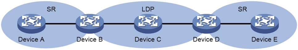
SR-MPLS hot standby
Hot-Standby refers to creating a backup LSP immediately after establishing the primary LSP, with the backup LSP always in a ready state. The Hot-Standby LSP provides protection for the entire LSP and represents an end-to-end traffic protection method.
As shown in Figure 38, configure Hot-Standby on ingress node A. Node A immediately creates a Hot-Standby LSP after creating the primary LSP, meaning an SR-MPLS TE tunnel contains two LSPs. If the head node detects a primary LSP failure, it switches traffic to the Hot-Standby LSP. When the primary LSP recovers from the failure, traffic switches back to it. Throughout this process, the SR-MPLS TE tunnel remains in Up state.
Figure 38 SR-MPLS TE hot-standby protection
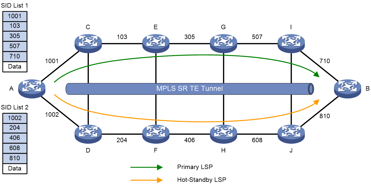
SR-MPLS TI-LFA
As shown in Figure 39, a data packet needs to be sent from Node A to Node F. After a failure occurs between Node B and Node E, Node B forwards the data packet to Node C. Because the cost between Node C and Node D is 100 and routing on Node C has not converged, Node C considers Node B as the next hop on the optimal path to Node F. Node C then sends the data packet back to Node B, creating a routing loop.
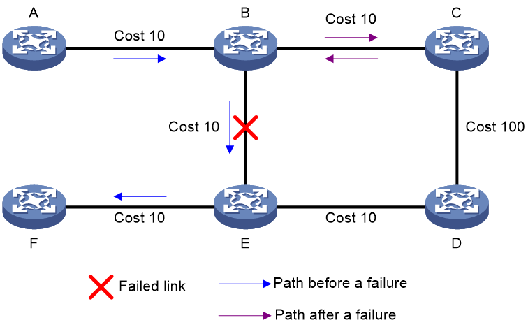
Deploy TI-LFA in the SR-MPLS network to resolve the issues mentioned above. As shown in Figure 40, when a fault occurs between node B and node E, node B activates the backup path calculated by TI-LFA. It specifies an explicit path B->C->D->E for the packet, ensuring that the packet is forwarded along the backup path.
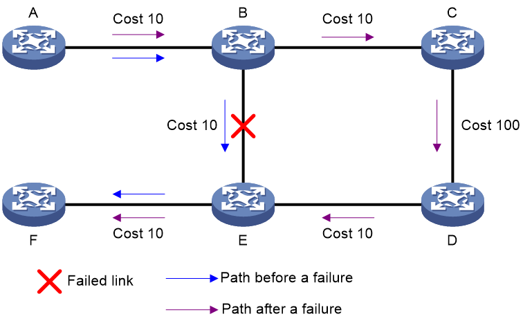
SR-MPLS BSID application
A Binding SID, acting as the Adjacency SID for SR-MPLS TE/SR-MPLS TE Policy tunnels, can facilitate label stitching and traffic steering into the tunnel.
Label stitching
The stitching technology primarily addresses the issue where headend devices cannot specify a complete path due to insufficient label stack depth on devices.
As shown in Figure 41, to establish a strict explicit path from A to B to C to D to E, if each device's label stack depth is sufficient, a label stack of (200, 300, 400) can be directly encapsulated. Assuming the device only supports two labels in the stack, Node B must act as a stitching node, introducing a stitching label 2000. Node B pre-distributes the label forwarding entry <Label_in: 2000, Label_out: (300, 400)>. Node A encapsulates the label stack (200, 2000), and upon reaching Node B, the label stack (200, 2000) is popped up and replaced with the label stack (300, 400), achieving the strict forwarding path from A to B to C to D to E.
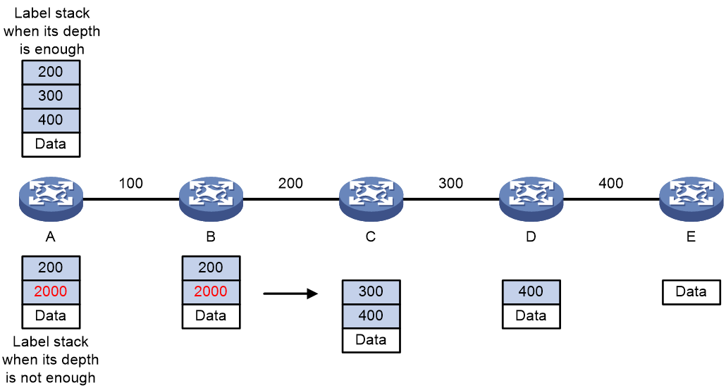
BSID-based traffic steering
After Device A receives a packet with the stack top label 16001, it searches its LFIB and determines that the label is a BSID. Then, Device A obtains the outgoing label stack and next hop (Device B), pops the BSID, pushes SID list {20002, 21003, 22004}, and forwards the packet to Device B. 20002 is the SID of the segment for a packet to travel from Device A to Device B. 21003 is the SID of the segment for a packet to travel from Device B to Device C. 22004 is the SID of the segment for a packet to travel from Device C to Device D.
Figure 42 BSID-based traffic steering
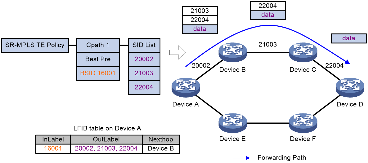
SR-MPLS for a multi-AS VPN
As shown in Figure 43, use a multi-AS SR-MPLS TE network to carry VPN traffic, providing a data channel for multi-AS VPN services. Deploy IGP SR within the autonomous system to establish intra-AS SR-MPLS TE tunnels. Deploy BGP-EPE between ASs for inter-AS SID allocation. Combine intra-AS SR-MPLS TE tunnels with inter-AS BGP-EPE peer SIDs to form multi-AS SR-MPLS TE tunnels, enabling inter-AS VPN traffic forwarding.