- Released At: 17-04-2024
- Page Views:
- Downloads:
- Table of Contents
- Related Documents
-
SDWAN Technology White Paper
Copyright © 2024 New H3C Technologies Co., Ltd. All rights reserved.
No part of this manual may be reproduced or transmitted in any form or by any means without prior written consent of New H3C Technologies Co., Ltd.
Except for the trademarks of New H3C Technologies Co., Ltd., any trademarks that may be mentioned in this document are the property of their respective owners.
The content in this article includes general technical information, some of which may not be applicable to the product you have purchased.
VPN instances and tenant isolation
IPsec protection for SDWAN tunnels
Security associations overview
Methods of SA generation and exchange
SDWAN tunnel establishment with NAT traversal
STUN client retransmission mechanism
Establishing SDWAN tunnels with NAT traversal
Preference-based link selection
Quality evaluation mechanism and quality policy
Bandwidth-based link selection
Bandwidth-based link selection policy
Link selection workflow summary
Preference-based link selection
Quality tolerant link selection
Bandwidth tolerant link selection
Link selection delay and suppression
Introduction to SaaS applications
Access methods for SaaS applications
SaaS path quality probe and evaluation
SaaS path optimization mechanism
Accessing SaaS applications through dynamically allocated IP addresses
Accessing SaaS applications through static IP addresses
Overview
Background
The development of cloud computing technology sparked a revolution in the IT industry, and Internet Plus drives the transformation of traditional industries. In 2014, Internet-related services to businesses exceeded those to consumers. Software Defined Wide Area Network (SDWAN) services, focusing on the corporate market and the wide area network (WAN) realm, emerged within such industry context and expectations.
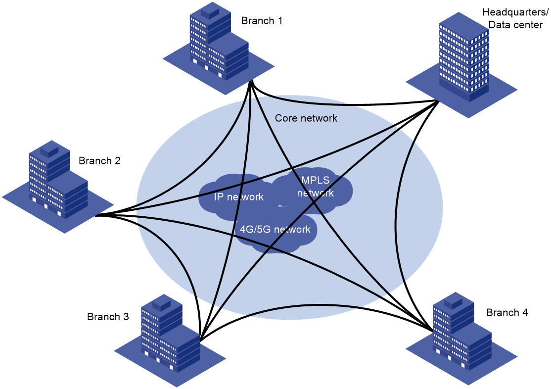
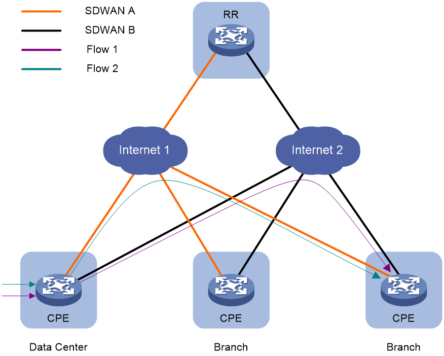
SDWAN is a VPN technology that applies SDN technology in WAN scenarios. As shown in Figure 1, the purpose of SDWAN technology is to help users lower WAN expenditure and enhance network connection flexibility. It provides safe and reliable interconnection services for widely dispersed enterprise networks, data center networks, etc.
Figure 1 SDWAN service scenario
Benefits
SDWAN has the following characteristics:
· Lowering the cost of network deployment: Introducing point-to-multipoint SDWAN tunnels has saved device performance. Only one tunnel needs to be established between the local site device and multiple remote site devices, enabling low-performance devices to support Full-Mesh network group.
· Simplify network deployment and maintenance for easy and quick network deployment.
¡ Only one BGP neighbor needs to be established between two devices, serving all private network routes of the VPN through a single BGP neighbor.
¡ Introduce the Route Reflector (RR), flexibly control user service topology based on the routing policy on the RR.
¡ A key advertisement mechanism has been introduced to remove the need for IPsec IKE negotiation between devices. The controller deploys IPsec policies on the Route Reflector (RR), which then directly sends the IPsec Security Associations (SAs) to each site's devices, significantly reducing their IPsec negotiation burden.
¡ Introduce the STUN protocol to establish tunnels between branches with dynamic IP addresses that have NAT translation using the STUN protocol.
· Improve user experience: Isolate users through VPN-instance and ensure secure transmission of user data via IPsec.
SDWAN implementation
Network model
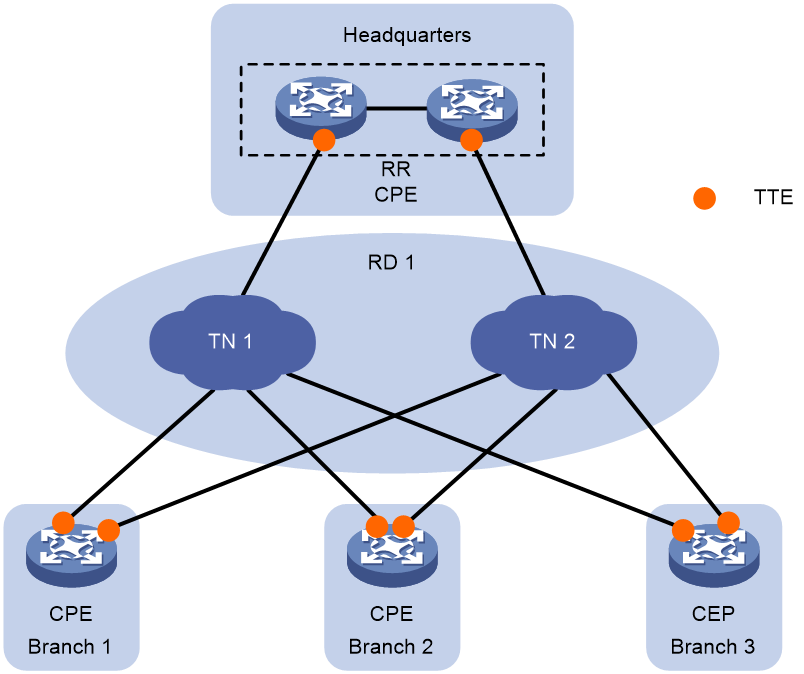
As shown in Figure 2, the typical network model of SDWAN includes the following parts:
· Customer provided edge (CPE)—Edge device of the customer network.
· Route reflector (RR)—Used to reflect transport tunnel endpoint (TTE) information and private routes between CPEs.
· Transport network (TN)—The wide-area access network provided by carriers, connecting branch sites. It mainly comprises dedicated carrier lines and the public Internet. The TN, identifiable by a TN ID or name, is fundamental to establishing the SDWAN Overlay network.
· Routing domain (RD)—Domain that contains transport networks that are reachable at Layer 3. SDWAN tunnels can be established only between CPEs or between CPEs and RRs in the same routing domain.
· Site ID—A site ID is a string of digits used to uniquely identify a site in the SDWAN network. The network controller allocates site IDs to all sites.
· Device ID—This is the unique identifier for devices that support the SDWAN function (SDWAN devices) within a site, allocated by the network administrator. A site usually contains one or two SDWAN devices.
· System IP—IP address of the device, which is allocated by the network administrator. Typically, the IP address of a certain Loopback interface on the device is used as the System IP.
· Interface ID—Device interface ID, allocated by the network administrator. On the same device, different tunnel interface IDs are unique.
· SDWAN tunnel—A point-to-multipoint logical channel between two SDWAN devices. Data and documents are transmitted between different sites through the SDWAN tunnel, thus connecting different sites. The physical egress interface of the tunnel is the WAN interface on CPE/RR. The WAN interface, belonging to the TN in the same RD, allows the WAN interfaces at both ends to communicate at the Underlay network layer. Two sites can connect via several carrier TNs, hence, multiple different tunnels can be established between the sites.
· Secure Sockets Layer (SSL) connection—In the SDWAN network, a CPE and an RR establish an SSL connection to exchange TTE information for control channel establishment.
· Transport tunnel endpoint (TTE)—Endpoint that connects an SDWAN device to a transport network and endpoint of an SDWAN tunnel. The main information of a TTE includes Site ID, TN ID, Private IP Address, Public IP Address, and encapsulation type of the tunnel. The TTE ID consists of Site ID, Device ID, and Interface ID, uniquely identifying a TTE. The TTE ID serves as an attribute of the TTE and is advertised to other network nodes through BGP routing.
· TTE connection—It refers to the point-to-point logical connection between two TTEs.
TTE
TTE is a crucial component of SDWAN technology, serving as the junction between the SDWAN devices and the transport network, as well as the endpoint of the SDWAN tunnel. The TTE ID consists of Site ID, Device ID, and Interface ID, uniquely identifying a TTE. SDWAN devices interact with TTE information to establish and maintain SDWAN tunnels dynamically, simplifying network management. The attributes of TTE include:
· Site ID
· Device ID
· System IP
· Site Role: This is the role of the device at its respective site, with possible values being RR, CPE, and NAT-transfer. NAT-transfer refers to NAT transmission equipment used to establish a forwarding path for CPE devices that traverse the public network through NAT.
· Interface ID.
· Transport network Name/ID
· Routing Domain Name/ID
· Encapsulation Type: Set to UDP, indicating the use of UDP encapsulation.
· NAT-Type: This refers to the type of NAT translation, which includes various values.
¡ Full Cone NAT: Complete Cone NAT.
¡ Restricted Cone NAT: Limited Cone-shaped NAT
¡ Port Restricted Cone NAT: Port-restricted cone-shaped NAT.
¡ Symmetric NAT: Symmetrical Network Address Translation
¡ No NAT: NAT does not exist.
¡ Type: Unknown
· The IP address and port number after NAT translation is referred to as the Public IP.
· Private IP: The IP address and port number before NAT translation.
· IPsec SPI
· IPsec authentication algorithm and cryptographic key.
· IPsec encryption algorithm and cryptographic key.
SDWAN packet encapsulation
SDWAN packets are divided into control packets and data packets.
· SDWAN control packets are used to advertise TTE information, EVPN routes, and the local public IP translated after NAT within the SDWAN network. For more information about NAT traversal, see "SDWAN tunnel establishment with NAT traversal."
· SDWAN data packets are used to forward user packets.
Control packet format
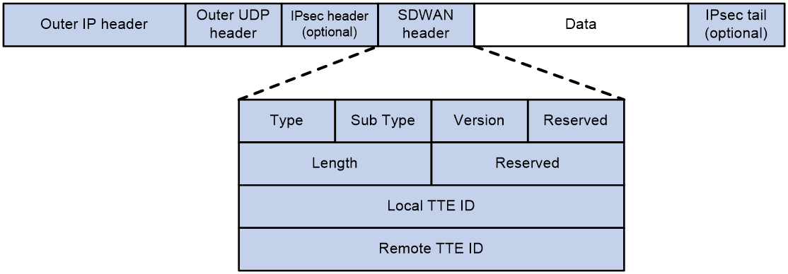
As shown in Figure 3, an SDWAN control packet encapsulation format is: adding a 16-byte SDWAN header, an 8-byte UDP header, and a 20-byte IP header to the outside of the data portion. If security protection is required for the packet, an IPsec header will also be encapsulated. The destination port number of the UDP header is the SDWAN UDP port number (default is 4799). The SDWAN header mainly includes the following fields:
· Type: Indicates the packet type with a length of 8 bits. When the value is 1, it represents SDWAN control packet; when it is 2, it represents SDWAN data packet.
· Sub Type: Indicates the subtype of the control packet, with a length of 8 bits. When the value is 1, it represents a NAT address probe request packet.
· Version: This refers to the SDWAN protocol packet number, which is currently fixed at 0.
· Reserved: This is a reserved field, and its value is permanently set to 0.
· Length: Indicates the length of the SDWAN header, which is 16 bits.
· Local TTE ID: Identifies a local TTE that is 32 bits in length.
· Remote TTE ID: Identifies a remote TTE with a length of 32 bits.
Figure 3 SDWAN control packet format
Data packet format
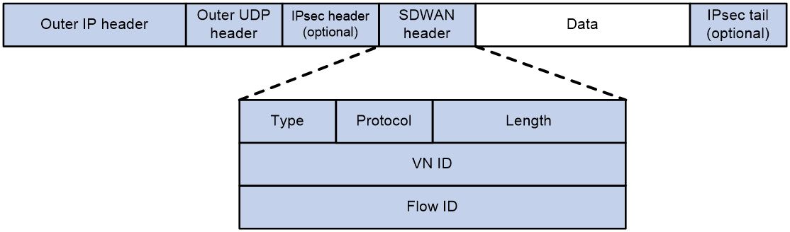
As shown in Figure 4, the SDWAN data packet encapsulation format is: adding a 12-byte SDWAN header, an 8-byte UDP header, and a 20-byte IP header to the raw data; if security protection is required for the packet, an IPsec header will also be encapsulated. The destination port in the UDP header is the SDWAN UDP port number (default is 4799). The SDWAN header mainly includes the following parts:
· Type: Indicates the type of the packet with a length of 8 bits. A value of 1 signifies an SDWAN control packet, while a value of 2 indicates an SDWAN data packet.
· Protocol: Indicates the type of the inner data packet with a length of 8 bits. A value of 1 represents an IPv4 data packet, while a value of 2 represents an IPv6 data packet.
· Length: This represents the length of the SDWAN header, which is 16 bits long.
· VN ID: Indicates the VN ID of the VPN-instance to which the SDWAN data belongs, with a length of 32 bits. If the data belongs to a public network instance, the value of this field is 0.
· Flow ID: Represents the flow ID to which the SDWAN data belongs, with a length of 32 bits. If the data hasn't been marked with a flow ID via QoS, the value will be 0.
Figure 4 SDWAN data packet format
BGP extensions
BGP IPv4 Tnl-Encap-Ext Address Family
To support SDWAN, BGP defines a new address family called BGP IPv4 tunnel-encap-ext address family. This address family is a subsequent address family of the IPv4 address family. The subsequent address family identifier (SAFI) is 74. Routes exchanged under this address family are IPv4 tunnel-encap-ext routes. IPv4 tunnel-encap-ext routes can include the following information in the Multiprotocol Reachable NLRI (MP_REACH_NLRI) attribute:
· TTE information—Includes site ID, transport network ID, public IP address, private IP address, tunnel encapsulation mode, and QoS information. CPEs use the information to set up data channels between each other. For more information about data tunnels, see "Data channel."
· SaaS path quality information—Includes link delay, jitter, packet loss ratio, and CQI. RIR uses the information to select the optimal path for application traffic. For more information about SaaS, see "SaaS path optimization."
Figure 5 MP_REACH_NLRI attribute in IPv4 Tnl-encap-ext routes
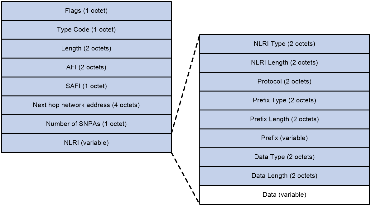
As shown in Figure 5, the MP_REACH_NLRI attribute in IPv4 tunnel-encap-ext routes contains the following fields:
· Flags—BGP attribute flags. The value is 0x90, which indicates that this attribute is an optional nontransitive attribute that includes complete information.
· Type Code—BGP attribute type. The value is 14.
· Length—Length of the MP_REACH_NLRI attribute.
· AFI—Address family identifier. The value is 1, which represents IPv4 address family.
· SAFI—Subsequent address family identifier. The value is 74, which represents IPv4 tunnel-encap-ext address family.
· Next hop network address—Next hop IPv4 or IPv6 address.
· Number of SNPAs—Number of Subnetwork Point of Attachments (SNPAs) in the subsequent field. If the value is 0, the attribute does not include an SNPA.
· NLRI—Network layer reachability information.
The network layer reachability information (NLRI) of the MP_REACH_NLRI attribute contains the following fields:
· NLRI Type—Type of NLRI. If the value is 1, this field includes IPv4 TTE information. If the value is 2, this field includes SaaS path quality information.
· NLRI Length—Length of NLRI.
· Protocol—Protocol stack of NLRI. The value is 2 for IPv4 or 10 for IPv6.
· Prefix Type—Prefix type of NLRI. The value is 1.
· Prefix Length—Prefix length of NLRI.
· Prefix—Prefix information of NLRI. For TTE information, the value is the TTE ID. For SaaS path quality information, the value is the site ID and device ID.
· Data Type—Type of the data portion in NLRI. The value is 2.
· Data Length—Length of the data portion in NLRI.
· Data—Data portion in NLRI. This field includes detailed TTE information or SaaS path quality information. For more information TTE and SaaS path quality information, see "TTE" and ""
· Data: This is the data section of NLRI. This field carries the specific content of TTE information or the quality information of the SaaS access path. For a detailed description of TTE, please refer to TTE; For a detailed introduction of SaaS access path quality information, see ''SaaS path optimization.''
EVPN Route
In the SDWAN tenant isolation scenario, the CPE advertises the private network route information in the VPN-instance to other CPEs in the form of EVPN IP prefix routes. To support SDWAN, the EVPN route has undergone the following expansion:
· A new SDWAN encapsulation type has been added in the TUNNEL_ENCAPSULATION_ATTRIBUTE attributes.
· The NLRI field of the IP prefix route carries the VN ID, which is used to distinguish private network routes belonging to different VPN instances.
Channel establishment
As shown in Table 1, an SDWAN network includes three types of channels: management channel, control channel, and data channel.
|
Channel type |
Channel connection type |
Location of the channel |
Functions |
|
Management channel |
NETCONF connection |
Between the controller and CPE/RR. |
· The controller issues configurations to the CPE/RR. · The CPE/RR reports the information needed for network maintenance to the controller. |
|
Control channel |
SSL connection |
Between RR and CPE |
Exchange TTE information between CPE and RR. |
|
BGP connection |
Between RR and CPE. |
The CPE sends TTE information and private network routes to the RR. The RR then reflects both the TTE information and private network routes to other CPEs. |
|
|
Data channel |
SDWAN tunnel |
Between CPEs and between RR and CPE. |
Forward the data packets. |
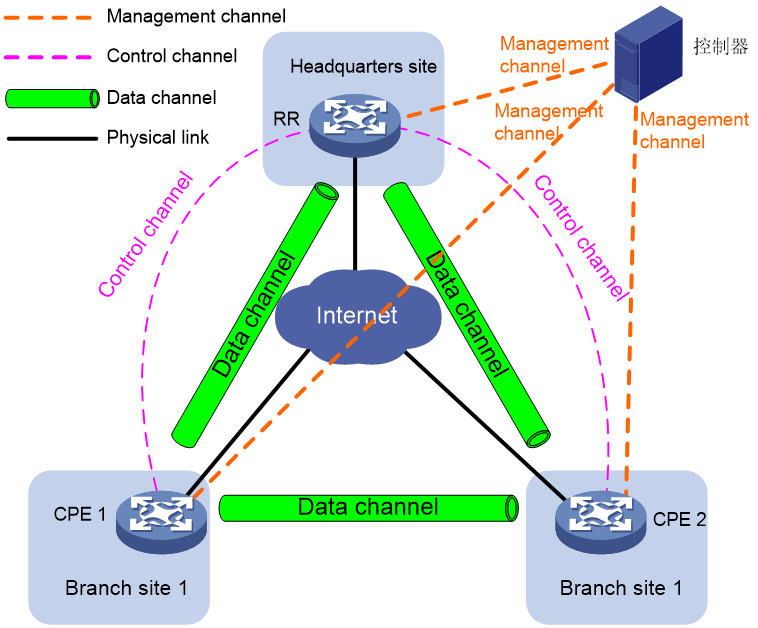
Management channel
The management channel refers to the connection between the controller and network devices such as CPE/RR. The following functions can be achieved through the management channel:
· The controller communicates configurations to network devices such as CPE/RR via management channels (for instance, channels established through the NETCONF protocol). These configurations primarily encompass network baseline settings, VPN service parameters, RIR, and IPsec, among others.
· Network devices such as CPE/RR report necessary network operation and maintenance information to the controller via the management channel. This primarily includes alarm data from the device, log entries, and network traffic performance collection information.
Control channel
The control channel is the channel used to advertise TTE information and private network routes between RR and CPE. The specific establishment process is:
The CPE establishes an SSL connection (control channel) with RR using the network-side egress interface address, where the CPE acts as an SSL client, known as the SDWAN SSL client; RR acts as the SSL server, referred to as the SDWAN SSL server.
CPE and RR exchange their respective TTE information through SSL packet interaction.
Upon receiving the transmitted TTE information from the peer, the CPE and RR compare the routing domain (RD), group ID, and transport network included in the TTE info. If the RD, group ID, and transport network are all identical, an SDWAN tunnel is established to the peer. If there are differences in the RD, group ID, or transport network, the SDWAN tunnel is not established. This SDWAN tunnel can be used for forwarding packets between the CPE and RR.
Upon completion of the SDWAN tunnel setup, the CPE and RR automatically add the UNR (User Network Route, customer network route) route to reach the opposing System IP locally.
A BGP connection (control channel) under the IPv4 Tnl-Encap-Ext address family and EVPN address family is established between CPE and RR based on System IP. TTE information and private network routes are advertised via this BGP connection.
Data channel
The data channel is a conduit for forwarding data packets between CPEs (Customer Premise Equipment) and from CPEs to RR. The specific establishment process is as follows:
The CPE transmits TTE information to RR via the IPv4 Tnl-encap-ext route.
RR reflects the TTE information to other CPEs.
Upon receiving the TTE information reflected by RR, the CPE compares the routing domain (RD), group ID, and transport network carried in the TTE information. If the RD, group ID, and transport network are all the same, it establishes an SDWAN tunnel to the peer CPE. If there are differences in the RD, group ID, or transport network, it does not establish an SDWAN tunnel.
After completing the SDWAN tunnel setup, the CPE automatically adds a UNR route to the local system for reaching the remote System IP.
To ensure secure transmission of data, data packets can be encrypted using IPsec. For a detailed introduction to IPsec, please refer to "2.10 IPsec Security for SDWAN Tunnels."
Route advertisement
As shown in Figure 7, inter-site route advertisement in an SDWAN network includes the following processes:
1. Each site advertises private routes to its local CPE.
2. CPEs advertise routes to each other.
3. Each CPE advertises private routes received from another site to its local site.
After these processes are completed, reachable routes between sites will be established.
Figure 7 Diagram of Route Information Release
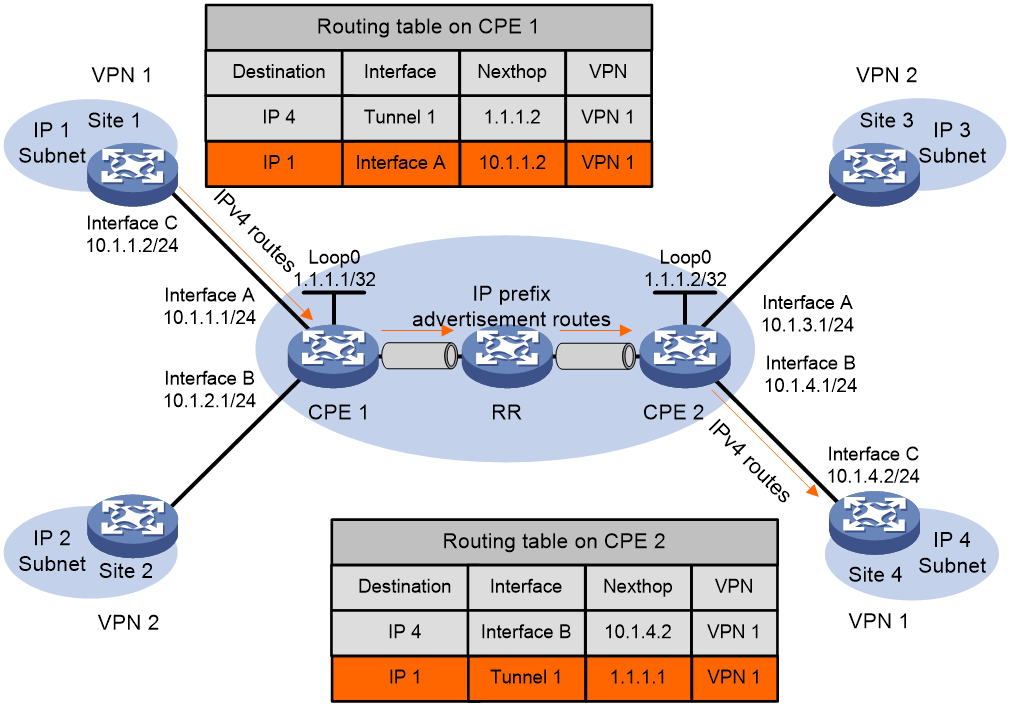
Advertising private routes from local site to local CPE
The local site uses static route, RIP, OSPF, IS-IS, EBGP or IBGP, to advertise the site's VPN routes to the local CPE. The local site advertises standard IPv4 routes to the CPE.
Advertising routes from local CPE to remote CPEs
1. After learning the VPN routing information from the local site, the CPE stores it in the routing table of the VPN instance.
2. The CPE encapsulates VPN route information into the IP prefix route, advertises it to the RR, carrying the RD and RT. Furthermore, the next-hop address of this route is the System IP of the local CPE 1.
3. The RR (Route Reflector) will reflect the received IP prefix to the remote CPE.
4. Upon receiving the reflected IP prefix routes from the remote CPE, the RR matches the Export Target attribute of the IP prefix route with the Import Target attribute of the VPN-instance it maintains. If a VPN-instance on the Remote CPE has an Import Target attribute that matches the same attribute value in the Export Target attribute of the route, the IP prefix route is received and added to the VPN routing table. In this case, the egress interface of the route is the SDWAN tunnel interface that received the route, and the next hop is the System IP of the Remote CPE.
Advertising routes from remote CPEs to remote sites
The supported routing methods are the same as the routing methods for advertising routes from the local site to the local CPE. A remote site can use multiple methods to learn private routes from its CPE. The methods include static route, RIP, OSPF, IS-IS, EBGP, and IBGP.
Packet forwarding
Figure 8 Data packet forwarding
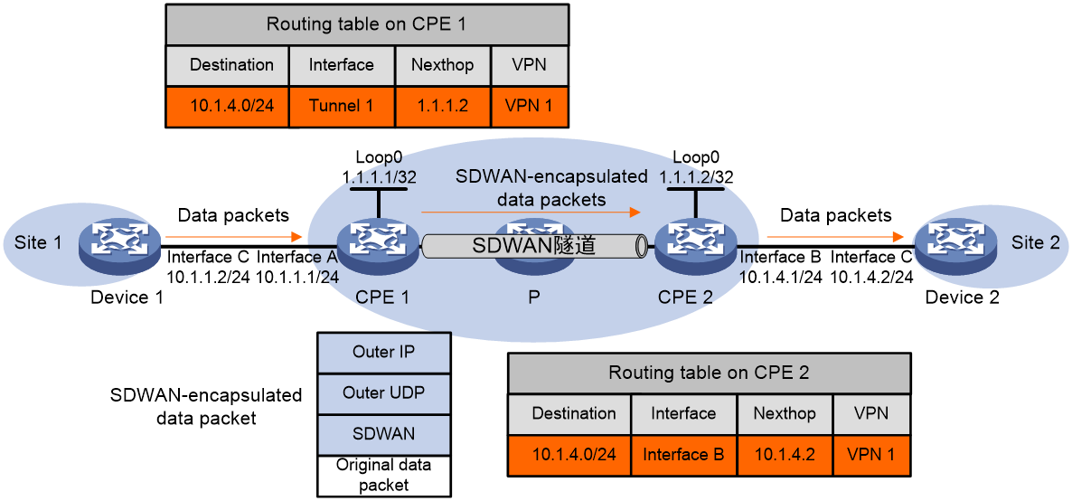
As shown in Figure 8, the process of forwarding a data packet is as follows:
1. The host within Site 1 sends an IP packet with a destination address of 10.1.4.3, which is then forwarded by Device 1 to CPE 1.
2. CPE 1 looks up VPN instance's routing table based on the interface where the packet arrives and the destination address. In it, the egress interface for the route table entry is the SDWAN tunnel interface, and the next hop is the System IP of CPE 2.
3. CPE 1 finds the remote TTE ID based on the detailed route information and encapsulates the packet with SDWAN encapsulation according to the TTE connection information. Then, the packet is forwarded through the egress interface of the SDWAN tunnel. The specific encapsulation information is as follows:
¡ The source and destination IP addresses in the outer IP header are the Source IP and Destination IP in the TTE connection information, respectively. The Source IP is the IP address of the physical egress interface of the SDWAN tunnel on CPE 1, while the Destination IP is the IP address of the physical interface that receives the SDWAN packet on CPE 2.
¡ The source port number of the outer UDP is the source UDP port number used when the configured SDWAN packet is encapsulated in UDP.
¡ The
VN ID in the SDWAN header is the same as the VN ID of the VPN-instance bound to
the interface that CPE 1 receives the packet.
In the SDWAN network, P forwards the packet based on the destination IP address and sends the packet to CPE 2.
CPE 2 performs decapsulation on the packet and determines the VPN-instance to which the packet belongs based on the VN ID in the SDWAN encapsulation. By looking up the routing table of the VPN-instance, the egress interface for the packet is identified. The decapsulated packet is then forwarded to Device 2.
Device 2 forwards the packet to the destination host according to the normal IP forwarding process.
VPN instances and tenant isolation
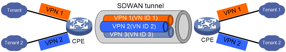
As shown in Figure 9, in SDWAN networking, VPN instances are used to provide isolation function for tenants.
· Control Plane: In the EVPN routes interacted between CPEs, the VN ID identify is carried to distinguish the private network routes of different tenants. Each VPN-instance is independent from each other, possessing its own forwarding table and routing table.
· Data plane (DP): Tenants access devices through their CPE's interface. The CPE identifies the tenant's VPN-instance associated with the interface, adding SDWAN encapsulation to the tenant's packets, and forwards them to the remote CPE. The SDWAN encapsulation carries the VN ID to identify the tenant's VPN. When the remote CPE receives the packets, it can identify the VPN-instance using the VN ID. The remote CPE then consults the forwarding table of the VPN-instance and forwards the packets to the tenant.
This isolation method allows multiple VPNs to share the same SDWAN tunnel, reducing the number of tunnels between devices and consuming less network resources, while also isolating traffic.
Flexible overlay topology
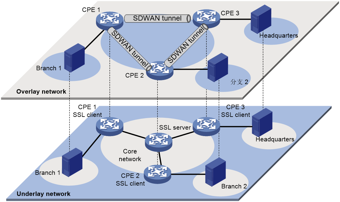
As illustrated in Figure 10, the flexible overlay topology means that based on the underlying Internetworking, the topology structure of the Overlay network can be flexibly controlled by configuring routing policies on RR.
Figure 10 Underlay and Overlay Networks
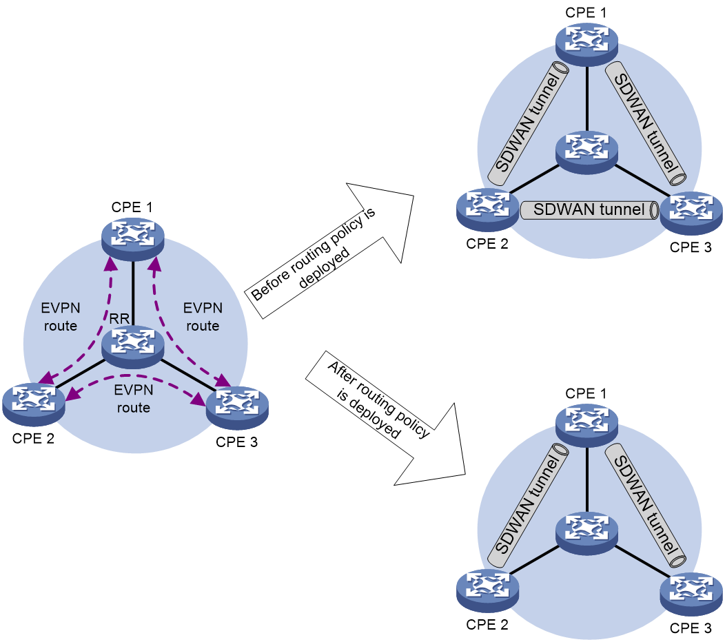
As shown in Figure 11, there is an SDWAN tunnel between CPE 2 and CPE 3 before the deployment of the routing policy. The traffic between CPE 2 and CPE 3 is directly forwarded through the SDWAN tunnel between them. Due to changes in tenant services, the traffic between CPE 2 and CPE 3 needs to be detoured to CPE 1 for forwarding. At this point, a routing policy can be deployed on RR to modify the next-hop address of the EVPN route sent by CPE 2/CPE 3 to the address of CPE 1, thereby flexibly changing the topology of the Overlay network.
Figure 11 Flexible Overlay Topology
IPsec protection for SDWAN tunnels
To ensure the confidentiality and integrity of data transmission in SDWAN tunnels, devices support the use of IPsec to provide security protection for SDWAN packets. IPsec offers two core security mechanisms: authentication and encryption. The authentication mechanism allows the receiver of the SDWAN data to verify the genuine identity of the data transmitter and ascertain whether the data has been tampered with during transmission. The encryption mechanism maintains the secrecy of the data by encrypting it to guard against eavesdropping during transmission.
IPsec provides the following specific security services for SDWAN data packets:
· Data confidentiality: Before transmitting user packets over the network, IPsec encrypts the packets for added security.
· Data Integrity: The recipient authenticates the IPsec packet received from the sender to ensure the data has not been tampered with during transmission.
· Data origin authentication: The receiving party verifies whether the transmitter of the IPsec packet is legitimate.
· Anti-Replay: The receiver can detect and refuse to receive outdated or duplicated IPsec packets.
Security associations overview
Security Association (SA) is the foundation and essence of IPsec. IPsec provides secure communication between two endpoints, which are referred to as IPsec peers. The SA is an agreement between IPsec peers on certain elements, such as the security protocol (AH, ESP, or a combination of both) they use, the encapsulation mode (transmission mode or tunnel mode) of the protocol packet, the authentication algorithm (HMAC-MD5, HMAC-SHA1, or SM3) they employ, the encryption algorithm (EA) (DES, 3DES, AES, or SM) they utilize, the shared key that protects data in a specific flow, and the key's time to live (TTL).
SAs are unidirectional. It requires at least two SAs for bidirectional communication between two peers, in order to separately secure the data flow in both directions. Moreover, If both peers wish to use Authentication Header (AH) and Encapsulation Security Payload (ESP) simultaneously for secure communication, each peer will construct an independent SA for each protocol.
An SA is uniquely identified by a triplet, which includes the Security Parameter Index (SPI), destination IP address, and security protocol number. The SPI is a 32-bit value used to identify the SA and is transmitted in the AH and ESP headers.
Methods of SA generation and exchange
The traditional IPsec uses IKE for autonegotiation to generate SAs, which are maintained by the IKE protocol. This method requires peer-to-peer IKE negotiation channels, resulting in low efficiency and bandwidth consumption. In the SDWAN network, a CPE generates an IPsec SA locally. The IPsec SA is firstly exchanged between the RR and the CPE through an SSL connection, and then is advertised to the RR via the BGP's IPv4 Tnl-encap-ext route, and reflected by the RR to other CPEs, achieving exchange of the IPsec SA. Different TTEs on the same SDWAN tunnel use the same IPsec SA, effectively reducing the device's IPsec negotiation pressure.
SDWAN devices regularly update IPsec SAs to further enhance network security.
IPsec anti-replay
Replayed packets, usually referring to packets that a device receives again after being processed by IPsec. IPsec detects replayed packets through a sliding window mechanism (anti-replay window). Both AH and ESP protocol packets have sequence numbers; if the received packet's sequence number is the same as a previously decapsulated packet or it appears earlier, meaning it has exceeded the anti-replay window range, the packet is considered a replayed packet.
Decapsulation of replayed packets is meaningless and involves cryptographic computations, which consume a lot of device resources, leading to a decrease in service availability and resulting in a denial of service attack. By enabling the IPsec anti-replay detection function, replayed packets detected can be discarded before decapsulation processing, thus reducing the consumption of device resources.
In an SDWAN network, the receipt order of BGP protocol packets and service data packets may greatly deviate from the normal sequence. Although this is not a deliberate replay attack, it may be considered as one by anti-replay checking, resulting in the discarding of service data packets, which affects normal service operations. Therefore, in such cases, you can avoid the erroneous discard of service data packets by disabling the IPsec anti-replay function. Alternatively, you can also adapt to the needs of normal service operations by appropriately increasing the width of the anti-replay window.
SDWAN tunnel establishment with NAT traversal
In the SDWAN network, users at branch sites often use private network IP addresses to save IP address resources. After converting the private IP address to the public IP address through NAT, users of that site can access other sites. The IP address of the packet sent by the CPE will change after passing through the NAT device. If the IP address after NAT translation cannot be obtained, the SDWAN channel between the CPE and CPE/RR cannot be established. To solve this problem, it is necessary to use static NAT or Session Traversal Utilities for NAT (STUN) to obtain NAT-related information and establish an SDWAN tunnel between CPEs by traversing NAT.
Static NAT
In the scenario where static NAT technology is used on a NAT device, the administrator manually specifies the public network IP address and port number post-NAT translation of the tunnel's source IP address and port number (i.e., the source UDP port number during SDWAN packet encapsulation) by deploying static NAT technology on CPE/RR. This eliminates the need to deploy STUN function for probing the public network IP address and port number post-NAT translation.
STUN
Session Traversal Utilities for NAT (STUN) is a protocol that addresses NAT traversal issues, used to determine whether a NAT device exists in the network for a tunnel module, as well as the IP address and port number assigned by the NAT device for communication endpoints. STUN transmits packets based on the UDP protocol, defaulting to port number 3478.
STUN network model
STUN operates in a Client/Server model, consisting of the STUN clients and STUN servers, with a typical group network setup as shown in Figure 12.
· STUN Client: The initiator of STUN probe, it actively transmits probe requests to the STUN server, determines the presence of NAT devices based on the server's response packet, and retrieves NAT information. It is usually deployed on CPE devices.
· STUN Server: The responder to STUN probe, it receives probe requests from the STUN client and provides the basis for judgment to the client by padding specific address and port information in the response packet. It is usually deployed on the public network.
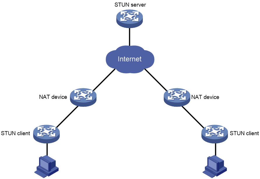
The STUN client and the STUN server interact through binding request and binding response protocol packets to sniff the IP address and port number after NAT translation, as well as the type of NAT.
NAT mapping and filtering
Concepts
NAT mapping and NAT filtering are two concepts often used in NAT traversal technology. In STUN, it is necessary to determine the type of NAT by passing through the NAT mapping type and NAT filtering method, thereby confirming whether STUN can work normally.
The related terms are as follows:
· Endpoint: A combination of an IP address and a port number. For instance, Endpoint (X, x) indicates an IP address of X and a port number of x.
· NAT Mapping: The NAT device maps packets actively sent from the private network to the public network. When a host in the private network initiates access to a host in the public network, the NAT device establishes a mapping table between the private network Endpoint and the public network Endpoint. Based on this mapping, it translates the private network Endpoint in the packet to the public network Endpoint for forwarding.
· NAT Filtering: NAT devices filter the packets actively sent from the external network to the internal network. To protect the internal network host from attacks, NAT devices filter the packets actively sent from the external network to the internal network, that is, they filter out illegal packets and forward regular communication packets.
NAT mapping type
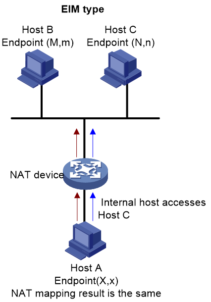
There are three types of NAT mappings: EIM, ADM, and APDM. Using Figure 13, Figure 14, and Figure 15 as examples, these three types of NAT mapping will be detailed in the following. Suppose the internal endpoint of the internal host, Host A, is (X,x), and its external endpoint after NAT mapping is (Y,y). The endpoint of the external host, Host B, is (M,m), and that of Host C is (N,n).
· Endpoint-Independent Mapping (EIM): NAT mapping is based solely on the internal network endpoint. It ignores the destination IP address and port number of the packet. Thus, any packet sent from the same internal endpoint to the external network will have the same NAT mapping result. As shown in Figure 13, for the internal endpoint (X,x), the mapped external endpoint is consistently (Y,y).
Figure 13 Diagram of EIM (Enterprise Information Management)
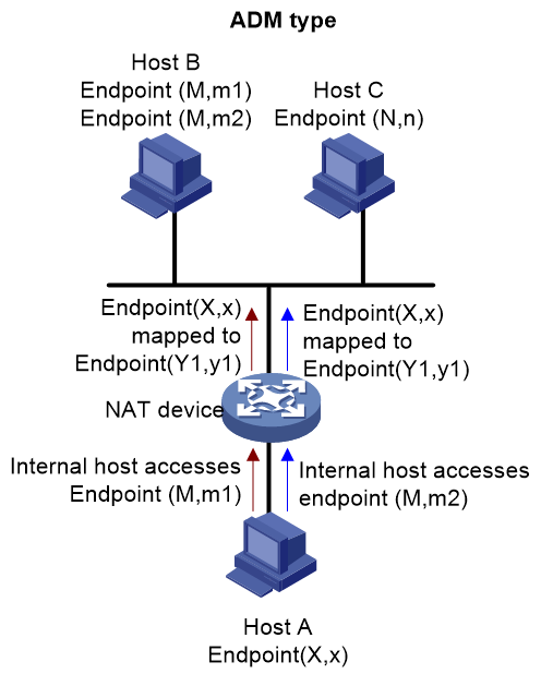
· ADM (Address-Dependent Mapping): It performs NAT mapping based on internal network Endpoint and the destination IP address of the packet, without considering the destination port number of the packet. That is, for any packet transmitted from the same internal network Endpoint to the same IP address with any port number in the external network, the NAT mapping result is the same. However, for any packet transmitted from the same internal network Endpoint to different IP addresses in the external network, the NAT mapping result is different. As shown in Figure 14, for the packets from internal network Endpoint(X,x) accessing Endpoint(M,m1) and Endpoint(M,m2) on Host B, the external network Endpoint after NAT mapping are all (Y1,y1).
Figure 14 ADM network diagram
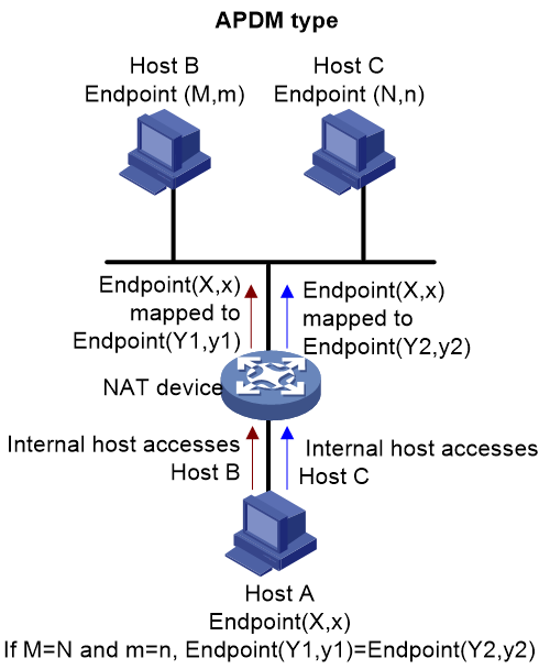
· APDM (Address and Port-Dependent Mapping): NAT mapping is based on internal network Endpoint and external network Endpoint. That is, for the same internal network Endpoint transmitting to the same external network Endpoint, the NAT mapping result is the same; for the same internal network Endpoint transmitting to different external network endpoints, the NAT mapping result is different. As shown in Figure 15, for the internal network Endpoint (X,x) accessing Host B, the NAT-mapped external network Endpoint is (Y1,y1); for the internal network Endpoint (X,x) accessing Host C, the NAT-mapped external network Endpoint is (Y2,y2).
NAT Filtering Method
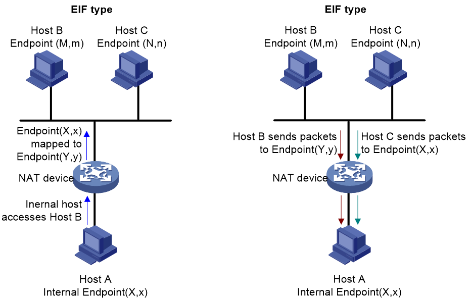
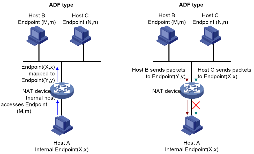
The NAT filtering methods include three types: EIF, ADF, and APDF. Detailed descriptions of these three NAT filtering types are provided with references to Figure 16, Figure 17, and Figure 18. Suppose internal network host A has an internal network endpoint of (X, x), which after NAT mapping becomes an external network endpoint (Y, y). External network host B has an endpoint (M, m), and host C has an endpoint (N, n).
· Endpoint-Independent Filtering (EIF): For an internal network Endpoint (X,x), as long as it has sent data to an external network host, the host can acquire the mapped external network Endpoint (Y,y) from the internal host NAT based on the source IP and source port of the data. Therefore, for any data sent to Endpoint (Y,y) by hosts from any external network, the NAT device will perform address translation and forward it to the internal network. If the mapping table on the NAT device does not contain an entry corresponding to the destination Endpoint of the received data from an external network host, the NAT device will discard such data packets.
· Address-Dependent Filtering (ADF): For an internal network Endpoint(X,x), only if it has previously transmitted a packet to an external network Host B with an IP address M, will the NAT device carry out address translation for packets sent to Endpoint(Y,y) by external network Host B using the external address M and any port number. Any packets from other external networks will be filtered by the NAT device.
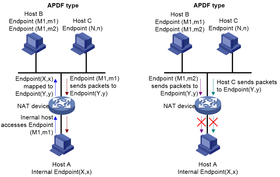
· APDF (Address and Port-Dependent Filtering): For internal network Endpoint (X,x), if it only transmits packets to external network Endpoint (M1,m1), then the NAT device will perform address translation only on packets sent from Endpoint (M1,m1) to Endpoint (Y,y) and forward them to the internal network. Any other external network packets will be discarded by the NAT device.
Figure 18 APDF diagram
NAT types
A NAT type is a combination of mapping type and filtering mode, and there are the following four combinations:
· Full Cone NAT: A combination of EIM and EIF.
All packets sent from the same private network IP address and port (IP1: Port1) to the NAT device will be mapped to the same public network IP address and port (IP: Port). In addition, any external host can communicate with the internal host via this public network IP address and port (IP: Port).
· Restricted Cone NAT: A combination of EIM and ADF.
All packets sent to the NAT device from the same private network IP address and port (IP1:Port1) will be mapped to the same public network IP and port number (IP:Port). Unlike Full Cone NAT, only the external hosts that have been previously accessed by the internal host can communicate with the internal host. Other external hosts are unable to communicate with the internal host.
· Port Restricted Cone NAT: A combination of EIM and APDF groups.
All packets sent from the same private network IP address and port (IP1:Port1) to a NAT device are mapped to the same public network IP and port number (IP:Port). Unlike Restricted Cone NAT, a public network host (IP2:Port2) can communicate with the private network host only if the private network host has previously accessed the public network host via (IP2:Port2).
· Symmetric NAT: A combination of APDM and APDF.
All packets sent from the same private network IP address and port (IP1:Port1) to a specific destination IP address and port will be mapped to the same public network IP address and port. If the same private network host transmits packets using the same source address and port number, but to different destinations, NAT will use different mappings. The prerequisite for a public network host (IP2:Port2) to communicate with a private network host (IP1:Port1) is that the private network host (IP1:Port1) has previously passed through (IP2:Port2) to visit the public network host.
STUN packet format
The STUN protocol packet is based on UDP transmission, and the encapsulation format of the protocol packet is as shown in Figure 19.
![]()
As shown in Figure 20, a STUN packet consists of two parts: the STUN packet header and the STUN packet attributes. The length of the STUN packet header is 20 bytes, followed by zero or more attributes.
Figure 20 STUN packet structure
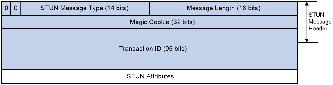
The STUN packet header includes the following fields:
· STUN Packet Type: The STUN packet type has a length of 14 bits. Currently, only STUN binding requests and STUN binding responses are supported among packet types.
· Packet Length: The length of the STUN packet is 16 bits (excluding the length of the packet header).
· Magic Cookie: A magic word with a length of 32 bits. The magic word contains a fixed value of 0x2112A442, used for the STUN server to detect if the STUN client can identify specific attributes. Additionally, when STUN and other protocols use the same port number, the magic word can distinguish STUN from other protocols.
· Transaction ID: A unique identifier for a STUN probe transaction, with a length of 96 bits. The Transaction ID is selected by the STUN client. In a STUN probe transaction, the STUN server returns a STUN binding response packet with the same Transaction ID as the STUN binding request packet sent by the STUN client. Also, the STUN server uses the Transaction ID to uniquely identify different probe requests from the STUN client.
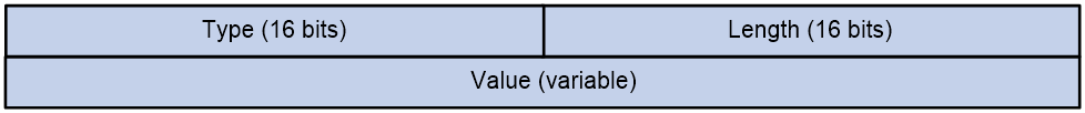
The attributes of STUN packets follow the TLV (Type/Length/Value) format, structured as shown in Figure 21. Among them, both the Type and Length fields are 16 bits long, while the length of the Value field is variable.
Figure 21 The structure of the STUN packet attributes.
Common types of STUN packet attributes include the following:
· CHANGE-REQUEST: The packet attributes carried in the binding request. The STUN client uses this attribute to request the STUN server to change the IP address and port number for transmitting the binding response packet.
· MAPPED-ADDRESS: This is a packet attribute carried in the binding response, which represents the IP address and port of the STUN client after address translation.
· XOR-MAPPED-ADDRESS: A packet attribute carried in the binding response, indicating the IP address and port of the STUN client after address translation. Unlike MAPPED-ADDRESS, the IP address carried in the XOR-MAPPED-ADDRESS attribute has undergone XOR processing.
· Response-Origin: The packet attributes carried in the binding response, indicating the IP address and port from which the STUN server transmits data.
· OTHER-ADDRESS: This is a packet attribute included in the binding response, representing another IP address and port number of the STUN server. Let's assume the IP address of the STUN server is Y1, the alternative IP address is Y2, the port number is YP1, and the alternative port number is YP2. Da is the destination IP address where the STUN client sends the binding request, and Dp is the destination port where the STUN client sends the binding request. If Da is Y1, then the IP address in OTHER-ADDRESS is Y2; if Da is Y2, then the IP address in OTHER-ADDRESS is Y1. If Dp is YP1, then the port number in OTHER-ADDRESS is YP2; if Dp is YP2, then the port number in OTHER-ADDRESS is YP1. When the STUN client requests the STUN server to transmit the binding response using a different IP address, if Da is Y1, then the IP address in the OTHER-ADDRESS of the binding response packet is Y2; if Da is Y2, then the IP address in OTHER-ADDRESS is Y1. Similarly, when the STUN client requests the STUN server to transmit the binding response using a different port number, if Dp is YP1, then the port number in OTHER-ADDRESS is YP2; if Dp is YP2, then the port number in OTHER-ADDRESS is YP1.
STUN operating mechanism
The STUN client interacts with the STUN server using STUN protocol packets, probes the type of NAT mapping and the method of NAT filtering on the NAT device in the network, and determines the type of NAT based on the probe result.
NAT mapping type probe
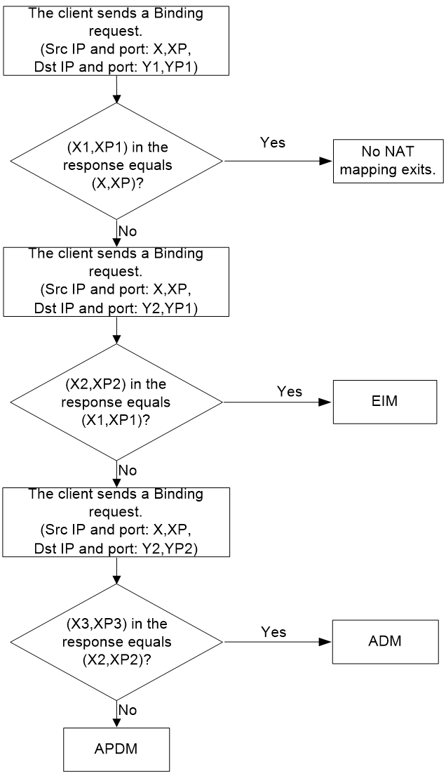
Assuming the IP addresses used by the STUN server for STUN probing are Y1 and Y2, with port numbers YP1 and YP2. The IP address and port number for the STUN client are (X, XP). The process of STUN conducting NAT mapping probing is shown in Figure 22, specific steps are as follows:
2. After receiving the binding response packet transmitted by the STUN server, the STUN client determines if the NAT-mapped Endpoint (X1, XP1) is the same as the internal network Endpoint (X, XP).
a. If Endpoint (X1, XP1) is the same as Endpoint (X, XP), the SUTN client believes that there is no NAT mapping.
b. If Endpoint (X1, XP1) is different from Endpoint (X, XP), then the STUN client uses step 3 to perform probe.
3. The STUN client sends a binding request from its Endpoint (X, XP) to the external Endpoint (Y2, YP1) of the STUN server. The STUN server responds with a binding response, using Endpoint (Y2, YP1), to the STUN client. The response includes: the external Endpoint (X2, XP2) of the STUN client after NAT mapping.
4. After receiving the binding response packet transmitted by the STUN server, the STUN client determines whether the mapped Endpoint (X2, XP2) after NAT is the same as the mapped Endpoint (X1, XP1) in step 1.
a. If Endpoint (X2, XP2) is the same as Endpoint (X1, XP1), then the STUN client considers the NAT mapping type to be EIM.
b. If Endpoint (X2, XP2) is different from Endpoint (X1, XP1), then the STUN client will use Step 5 for probing.
6. Upon receiving the binding response packet transmitted by the STUN server, the STUN client determines whether the NAT-mapped Endpoint (X3, XP3) matches the NAT-mapped Endpoint (X2, XP2) in step 3.
a. If endpoint (X3, XP3) is the same as endpoint (X2, XP2), the STUN client considers the NAT mapping type to be Address-Dependent Mapping (ADM).
b. If Endpoint (X3, XP3) is different from Endpoint (X2, XP2), then the STUN client considers the NAT mapping type to be APDM.
Figure 22 NAT mapping type probe
NAT filtering mode probe
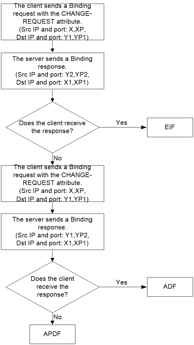
Assume the IP address of the STUN server is Y1, with an alternative IP address Y2, and the port number is YP1 with an alternative port number YP2. The IP address and port number for the STUN client are (X, XP). The process of STUN performing NAT mapping probe is shown as in Figure 23, with detail steps as follow:
1. The STUN client sends a binding request from the source address and source port, Endpoint (X, XP), to the STUN server's external Endpoint (Y1, YP1), carrying the CHANGE-REQUEST attributes in the request packet. This request requires the STUN server to change the IP address and port number to transmit the binding response. The STUN server then transmits the binding response to the STUN client from Endpoint (Y2, YP2).
2. The STUN client makes the following judgment based on whether it can receive a response packet:
a. If the STUN client receives a binding response packet, it considers the NAT filtering type to be EIF.
b. If the STUN client does not receive the binding response packet, then the STUN client uses step 3 to perform probe.
3. The STUN client sends a binding request from Endpoint (X, XP) to the STUN server's public Endpoint (Y1, YP1), carrying the CHANGE-REQUEST attributes in the request packet, asking the STUN server to change the port ID for transmitting the binding response. The STUN server uses Endpoint (Y1, YP2) to send the binding response to the STUN client.
4. The STUN client determines the following based on whether it receives response packets:
a. If the STUN client receives a binding response packet, it perceives the NAT filtering type as ADF.
b. If the STUN client does not receive the binding response packet, the STUN client perceives the NAT filtering type as APDF.
Figure 23 Flowchart for NAT filtering method detection
STUN client retransmission mechanism
STUN is based on the UDP transmission protocol, and STUN protocol packets may be discarded during transmission. The reliability of STUN protocol packet transmission can be improved through the retransmission mechanism of the STUN client. The specific mechanism is as follows:
After the STUN client transmits the binding request packet, if it does not receive a binding response packet within a certain time, the STUN client will retransmit the binding request packet at set time intervals.
When the STUN client receives a binding response packet, or the number of STUN packet retransmissions reaches the maximum, the STUN client will stop retransmitting.
If the STUN client retransmits the STUN packet to the maximum number of times and still does not receive the binding response packet, the STUN client considers the transmission of the binding request packet to have failed, unable to perform STUN probe.
Establishing SDWAN tunnels with NAT traversal
In SDWAN networks, CPE is usually deployed as a STUN client and RR as a STUN server. By interacting with the server, the client can detect the presence of NAT devices in the network and determine the translated IP address and port number after passing through the NAT device. After detecting the translated IP address and port number, the STUN client uses this IP address to establish an SDWAN tunnel with other CPEs. If the CPEs cannot directly establish a data channel, they need to achieve intercommunication through the deployment of a NAT transfer (NAT transmission) device in the public network.
Figure 24 SDWAN tunnel establishment with NAT traversal
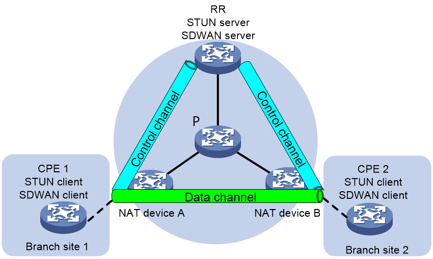
Figure 25 SDWAN tunnel establishment with NAT traversal (deployed with a NAT transfer)
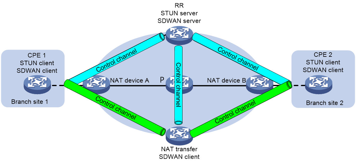
The deployment of the SDWAN network with a NAT transfer is as shown in Figure 25. The process of establishing a SDWAN tunnel through NAT is explicated below, using this network as an example.
Establishing control channels
1. The STUN clients and STUN server exchange STUN protocol packets. Each STUN client obtains the local NAT type, public IP address (public IP address translated after NAT when the STUN client accesses the STUN server), and port number.
2. The SDWAN clients and SDWAN server establish SSL connections. Then, they exchange TTE information, including the NAT type and public IP addresses obtained through STUN.
3. When CPE 1, CPE 2, and the NAT transfer receive TTE information from the RR, they compare the routing domain in the TTE information with the routing domain in the local TTE information. If the routing domains are the same one, they establish SDWAN tunnels destined for the RR. The destination IP address of the tunnels is the public IP address in the TTE information of the RR. If the routing domains are different, they do not establish SDWAN tunnels.
If the NAT transfer belongs to the public network, the RR establishes an SDWAN tunnel destined for the public IP address of the NAT transfer. The public IP address is the public IP address in the TTE information of the NAT transfer.
If the NAT type in the TTE information of CPE 1 and CPE 2 is full cone NAT, the RR establishes SDWAN tunnels destined for the public IP addresses of the CPEs. The public IP addresses are the public IP addresses in the TTE information of the CPEs.
If the NAT type in the TTE information of CPE 1 and CPE 2 is port restricted full cone NAT, restricted full cone NAT, or symmetric NAT, the RR cannot access CPE 1 or CPE 2 through the public IP addresses of the CPEs in the TTE information. The RR cannot establish SDWAN tunnels to the CPEs according to the currently obtained TTE information. To establish SDWAN tunnels from the RR to the CPEs:
a. CPE 1 and CPE 2 periodically send SDWAN control packets to the RR through the SDWAN tunnels established from the CPEs to the RR.
b. The RR uses the outer source IP addresses of the received SDWAN control packets as the public IP addresses of the CPEs. The RR establishes SDWAN tunnels destined for the public IP addresses.
5. After SDWAN tunnel establishment, CPE 1, CPE 2, the NAT transfer, and the RR add user network routes (UNRs) destined for the system IP addresses of peer devices.
6. CPE 1, CPE 2, the NAT transfer, and the RR establish BGP connections (control channels) under the IPv4 tunnel-encap-ext address family based on the system IP addresses.
Establishing data channels
1. After CPE 1, CPE 2, the NAT transfer, and the RR establish BGP connections (control channels), CPE 1, CPE 2, and the NAT transfer advertise TTE information to the RR through IPv4 tunnel-encap-ext routes. The RR reflects the TTE information to its BGP neighbors.
2. The CPEs compare their NAT types to determine whether they can establish direct data channels. Table 2 shows the data channel compatibility for different NAT types.
¡ If the CPEs can establish a direct data channel, the establishment procedure is the same as step 4 in "Establishing control channels."
¡ If the CPEs cannot establish a direct data channel, you must deploy a NAT transfer in the network. The CPEs each establish a data channel to the NAT transfer. Inter-CPE data is first forwarded to the NAT transfer through a data channel. Then, the NAT transfer forwards the data to the destination CPE through the other data channel. The procedure for establishing a data channel between a CPE and a NAT transfer is the same as that for establishing an SDWAN tunnel between a CPE and an RR. For more information, see step 4 in "Establishing control channels."
Table 2 Data channel compatibility for different NAT types
|
CPE 1 NAT type |
CPE 2 NAT type |
Support for CPE-CPE direct tunnels |
NAT transfer required for CPE intercommunication |
|
Non-NAT |
Full cone NAT |
Yes |
No |
|
Non-NAT |
Port restricted full cone NAT or restricted full cone NAT |
Yes |
No |
|
Non-NAT |
Symmetric NAT |
Yes |
No |
|
Non-NAT |
Unknown type |
Yes |
No |
|
Non-NAT |
Static NAT |
Yes |
No |
|
Full cone NAT |
Full cone NAT |
Yes |
No |
|
Full cone NAT |
Port restricted full cone NAT or restricted full cone NAT |
Yes |
No |
|
Full cone NAT |
Symmetric NAT |
Yes |
No |
|
Full cone NAT |
Unknown type |
Yes |
No |
|
Full cone NAT |
Static NAT |
Yes |
No |
|
Port restricted full cone NAT or restricted full cone NAT |
Port restricted full cone NAT or restricted full cone NAT |
Yes |
No |
|
Port restricted full cone NAT or restricted full cone NAT |
Symmetric NAT |
No |
Yes |
|
Port restricted full cone NAT or restricted full cone NAT |
Unknown type |
No |
Yes |
|
Port restricted full cone NAT or restricted full cone NAT |
Static NAT |
Yes |
No |
|
Symmetric NAT |
Symmetric NAT |
No |
Yes |
|
Symmetric NAT |
Unknown type |
No |
Yes |
|
Symmetric NAT |
Static NAT |
Yes |
No |
|
Unknown type |
Unknown type |
No |
Yes |
RIR-SDWAN
About RIR-SWAN
Traditional link selection is generally based on link overhead or routing policy, and cannot select the most suitable link according to the actual service requirements. Resilient Intelligent Routing (RIR) can select the most suitable link for different service traffic based on link requirements, such as link quality and link bandwidth. If the currently selected link for service traffic no longer meets the requirements due to link state changes, RIR can also automatically switchover the traffic to another link that meets the requirements.
As shown in Figure 26, RIR can be applied to the SDWAN networking environment. RIR can choose different SDWAN tunnels for various service traffic transmitted between CPEs based on factors such as link preference, link quality, and link bandwidth.
Figure 26 RIR in SDWAN scenario
Flow template
A flow template defines link selection policies for a type of service flow. A flow ID uniquely identifies a flow template.
The device applies the link selection policies under a flow template to the service flow marked with the flow ID of the flow template.
The device supports using QoS policies to mark flow IDs for service flows. After QoS identifies the service of a packet based on the quintuple and DSCP of the packet, it assigns a flow ID to the packet. Then, RIR will perform link selection for the packet based on the flow template that uses the flow ID.
The flow ID is marked only in the RIR process, and it will not be added to any outgoing packets.
RIR-SDWAN links
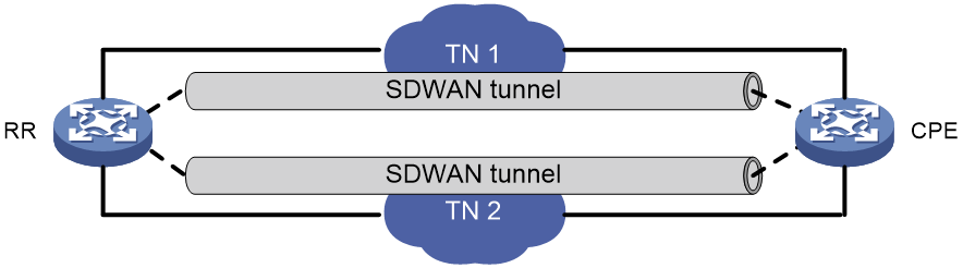
In the SDWAN network construction, a link is an SDWAN tunnel, which becomes a TTE (Transport Tunnel Endpoint) connection between the two CPEs. Each SDWAN tunnel is connected to a transport network, which can be uniquely identified by its network name. RIR distinguishes different links by the names of the transport networks used by the SDWAN tunnels. As shown in Figure 27, RR has established one SDWAN tunnel to the CPE through TN 1 and TN 2 respectively.
Preference-based link selection
Link preference
You can assign a preference to a link based on factors such as the service requirements, the link conditions, and the link cost. RIR preferentially selects links with higher preference.
RIR-SDWAN supports assigning a link preference to an SDWAN tunnel by its transport network name in flow template view.
Link selection rules
You can assign the same preference value to different links in the same flow template.
RIR selects a link for a type of service flows from the links in the flow template in descending order of link preference.
· If the links with the highest preference cannot meet the service requirements, RIR tries the links with the second highest preference, and so forth to the links with the lowest preference.
· If the flow template has two or more links with the same preference, RIR performs link selection based on RIR link load sharing criteria.
Quality-based link selection
Link probe mechanism
Intelligent routing conducts link probing on the links to be selected, and based on the probe results, it implements link prioritization based on link quality.
Intelligent routing defines two types of link probe methods:
· Link connectivity detection: The connectivity of each link is detected using SDWAN keepalive and BFD functions.
· iNQA link quality detection: Employing the iNQA function to detect the delay, jitter, and packet loss rate of each link.
Link connectivity probe
The device can detect the connectivity of the TTE connection on the SDWAN tunnel through either BFD or Keepalive methods. When a fault occurs in the TTE connection on the SDWAN tunnel, the device can quickly detect the fault for timely processing, such as switching traffic to another TTE connection.
The BFD method detects the connectivity of all TTE connections in the SDWAN tunnel by periodically transmitting BFD control packets to the other end of the TTE connection. If no BFD control packet is received from the other end during the detection period, the TTE connection between the local end and the other end is considered unreachable.
The Keepalive method detects the continuity of all TTE connections on the SDWAN tunnel by transmitting Keepalive request packets to the other end at specified time intervals.
· If the local end receives a Keepalive response packet from the remote end within the time interval of transmitting a Keepalive request packet, the local end considers the TTE connection between both ends to be reachable.
· If the local end does not receive the Keepalive response packet transmitted by the remote end within the time interval for transmitting Keepalive request packets, the local end will attempt to resend the Keepalive request packet. If the Keepalive response packet is not received within the time interval for transmitting Keepalive request packets multiplied by the maximum consecutive allowed times of not receiving Keepalive response packets, the local end considers the TTE connection with the remote end unreachable and will no longer use this TTE connection to forward packets.
iNQA link quality probe
Introduction to iNQA
Intelligent Network Quality Analyzer (iNQA) is a detection mechanism suitable for large-scale IP networks, capable of rapidly measuring network performance. Currently, iNQA supports loss measurement (LM), measuring bidirectional packet loss situations, including the number of lost packets, packet loss rate, byte count loss, and byte loss rate. Utilizing these results, the loss time, location, and severity can be quickly determined.
In the SDWAN network, an iNQA measurement instance is initiated based on each TTE connection, probing the packet loss rate, latency, and jitter of the TTE connection.
Concepts
As shown in Figure 28, it depicts the iNQA network model, which includes the following key concepts: Measurement Point (MP), Collector, Analyzer, and Atomic Measurement Span (AMS), etc.
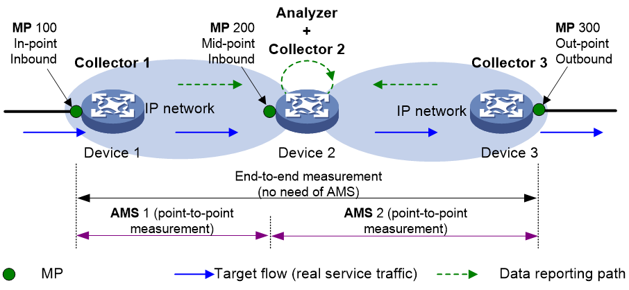
· Collector: Responsible for the management and control of Measurement Points (MPs), periodically collects statistical data generated by MPs and reports to the Analyzer.
· Analyzer: Responsible for collecting statistical data sent by the Collector, as well as finalizing the aggregation and calculation of the data.
· Target flow: Refers to the target objects counted by iNQA, which are the service packet flows in the network that conform to the specified matching rules. Users can define a target flow through the source IP address/network segment, destination IP address/network segment, protocol type, source port number, destination port number, and DSCP parameter. These parameters can be combined arbitrarily to match service packets. The more specified parameters, the more accurate the target flow is.
¡ MP Type: Includes In-point, Out-point, and Mid-point.
- In-point—An ingress point that the flow enters the network.
- Out-point—An egress point that the flow leaves the network.
- Mid-point: This represents the midpoint of the target flow's transmission path for measurement.
¡ Packet Orientation: Includes Inbound and Outbound, mainly used to specify the object to be counted. Specify as Inbound attributes when you need to count the number of packets entering the interface; Specify as Outbound attributes when counting the number of packets leaving the interface.
· AMS: Configured on Analyzer, it is used to define a measurement span. The packet loss location can be checked step by step through the AMS. Multiple AMS can be configured under one instance. Each AMS is bound to any MP on the Collector under this instance, enabling the summarization and computation of data for any forward, reverse, or bidirectional flow in a network section.
Each AMS has an In-MP group and Out-MP group. The In-MP group is a collection of MPs where traffic enters in this section of AMS, while the Out-MP group is a collection of MPs where traffic exits in this section of AMS.
· Instance: In actual networks, it's often necessary to measure the packet loss rate of multiple target flows on the same device. iNQA implements independent measurement and statistics of different target flow packet loss rates through instances.
An instance, a logical concept, is the smallest configuration unit of iNQA. In an instance, parameters such as target flow, measurement direction, measurement location, and measurement period can be specified to monitor and compile statistics of packet loss in the designated target flow. By binding a target flow under one instance, and creating instances with the same numbers on Collector and Analyzer respectively, packet loss of the target flow can be monitored and statistically analyzed. With multiple instances configured to bind different target flows, packet loss of various target flows can be simultaneously measured and assessed.
· Color bits, also known as flag bits, periodically tag target flows, achieving periodic sampling and statistics of the target flows. iNQA uses the 5th to 7th bits of the Type of Service (ToS) field in the IPv4 packet header as the color bits.
Operating mechanism
iNQA is a model that collects data from multiple points and calculates it at a single point. Multiple Collectors gather and report packet counts periodically, while a single Analyzer aggregates and calculates measurement data periodically.
iNQA is based on time synchronization. Before the measurement starts, it is required that all Collectors have synchronized their time, ensuring each Collector can carry out packet coloring, reporting, and statistics based on the same period. If the time is not synchronized, the calculation result of iNQA will be inaccurate. Whether the Analyzer and Collector's time is synchronized does not affect the calculation result, but for convenience of management and maintenance, it is recommended that the time of Analyzer and all Collectors remain synchronized. iNQA uses Network Time Protocol (NTP) or Precision Time Protocol (PTP) for time synchronization.
Packet loss rate
The packet loss calculation is based on the principle of conservation of packets, which states that the number of incoming and outgoing packets in a network should be equal over a certain period of time (multiple periods). If they are not equal, it indicates that there is packet loss within the network.
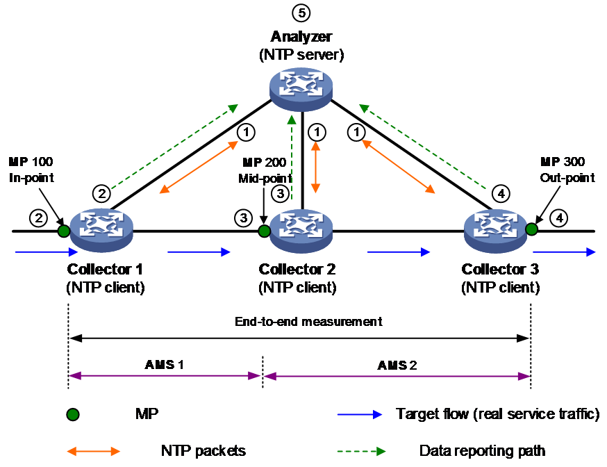
Taking the networking example as shown in Figure 29, the target traffic passes through three devices in the network. The Collector and NTP client are deployed on these three devices, while the Analyzer and NTP server are deployed on the multi-tenant unit switch (MTU-s). The traffic is measured to see if any packets are lost when entering from Measurement Point (MP) 100 and passing through MP 200, as well as when it flows out from MP 300.
The workflow of iNQA is as follows:
1. The Analyzer and all Collectors synchronize time via the Network Time Protocol (NTP).
2. Collector 1, on the packet entering the Measurement Point (MP), filters the target flow from the service flow based on the matching rule, alternately colors the packets for one period and does not color for another period, while counting the packets per period and reporting to Analyzer.
3. Collector 2, stationed on the intermediate Measurement Point (MP), filters out the target flow from the service flow based on the matching rule. It counts the packets periodically and reports them to the Analyzer.
4. Collector 3 filters out the target flow from the service flow on the outgoing Measurement Point (MP) based on the match rule. It then removes the coloring from the colored packets, counts the packets periodically, and reports the data to the Analyzer.
5. The Analyzer performs packet loss analysis for the same period, instance, and traffic, calculating the number of lost packets, the packet loss rate, the byte count lost, and the byte loss rate.
Number of lost packets = Number of incoming packets at the ingress – Number of outgoing packets at the egress
Packet loss rate = Number of lost packets / number of incoming packets at the ingress.
Number of lost bytes = Number of incoming bytes at the ingress – Number of outgoing bytes at the egress
Byte loss rate = Number of lost bytes / Number of incoming bytes at the ingress
¡ Packet loss = Number of packets at MP 300 – Number of packets at MP 100
¡ In AMS 1: Packet loss = Number of packets at MP 100 – Number of packets at MP 200
¡ In AMS 2: Packet loss = Number of packets at MP 200 – Number of packets at MP 300
Delay and jitter detection
For example, as shown in Figure 29, in a specific network group, Collector 1 colors the first packet for delay identification within a period and records the transmit timestamp SndTime 1. Collector 2 identifies this delay-colored packet and records the receive timestamp RcvTime 2 and the transmit timestamp SndTime 2. Similarly, Collector 3 identifies this delay-colored packet and records the receive timestamp RcvTime 3 and the transmit timestamp SndTime 3. The network delay for this period is calculated as Delay = RcvTime 2 + RcvTime 3 - SndTime 1 - SndTime 2.
Quality evaluation mechanism and quality policy
SLA
The Service Level Agreement (SLA) is used to differentiate the varying quality requirements for different service operations on a link. The SLA defines various thresholds used for assessing link quality, including latency, jitter, and packet loss rate. Intelligent routing is based on the SLA to implement a quality strategy for service traffic, that is, users can specify different quality policies with different SLA requirements for different service traffic.
Quality Assessment
The RIR assesses the quality of each link based on the Comprehensive Quality Indicator (CQI) algorithm. The working mechanism of the CQI algorithm is as follows:
When the detected individual quality (delay, jitter, or packet loss rate) by iNQA probe is less than or equal to the corresponding quality threshold under the SLA, it is considered that the single CQI value is 100.
When the result of a single quality probe exceeds the corresponding quality threshold under SLA, the single CQI value (delay CQI value Ds, jitter CQI value Js or packet loss rate CQI value Ls) equals (single threshold * 100) divided by the single quality probe result.
The comprehensive quality CQI value is calculated as (x* Ds + y*Js + z* Ls) / (x + y + z). Here, x, y, and z respectively represent the weights of delay, jitter, and packet loss rate, with a value range of 0 to 10 and cannot all be zero.
To avoid frequent link switchovers, the device uses an approximate Comprehensive Quality (CQI) value to evaluate the quality of the link during routing selection. The approximate CQI value is the largest multiple of 5 that is not greater than the Comprehensive Quality CQI value. For instance, if the Comprehensive Quality CQI value is 82.5, the approximate CQI value would be 80.
Quality Policy
When CPE selects a route for service traffic based on link quality, if a quality policy is specified for the traffic, the CPE will calculate the composite quality approximation CQI value according to link probe and SLA, and select the route based on this value. For a candidate link of a specific service traffic:
· If the overall quality of the link, approximated by the CQI value, is less than 100, it is considered that the link does not meet the quality requirements of the service.
· If the comprehensive quality of the link approximates a CQI value of 100, it is deemed to meet the service quality requirements.
If a quality policy is not specified for this service traffic, the link quality factor is not considered when selecting a route. It is directly assumed that the link quality meets the service quality requirements.
Bandwidth-based link selection
By selecting routes based on link bandwidth, not only can we choose links that meet the bandwidth requirements for service traffic, but we can also use each link's bandwidth in a balanced way. This aims to avoid the situation where an individual link's bandwidth usage is too high, or even causing link congestion.
Link bandwidth
When selecting a path based on link bandwidth, the device will choose the appropriate link for service traffic based on multiple factors such as the already used bandwidth of the optional links and their physical interfaces, total link bandwidth, and the expected bandwidth usage of the session. The bandwidth of the link is the tunnel interface bandwidth, and the bandwidth of the physiological interface to which the link belongs is the egress interface bandwidth for transmitting tunnel packets.
Meanwhile, the device uses the session as the smallest granularity, not the service type, to perform link bandwidth-based routing for more refined link bandwidth management. The session is uniquely defined by the 5-tuple, such that if any element of the source IP address, destination IP address, source port, destination port, or transport layer protocol in the packet is different, it belongs to a different session.
Bandwidth-based link selection policy
When intelligently selecting a route for a session's traffic, the device will obtain the estimated bandwidth the session will use in real-time, and conduct bandwidth detection based on the obtained bandwidth. If it cannot be obtained, the manually configured estimated bandwidth of the session will be used for bandwidth detection. If the following conditions are met, the candidate link's current available bandwidth is considered to meet the session's bandwidth requirements, and the bandwidth detection passes:
· The sum of the used bandwidth of the physical interface to which the optional link belongs and the bandwidth expected to be used by the session is less than 80% of the total bandwidth of the physical interface to which the optional link belongs.
· The sum of the used bandwidth and the anticipated session usage on the selected link is less than 80% of the total bandwidth of the selected link.
When different sessions of the same service type use the same routing policy, the routing results might differ.
Load sharing
When multiple links are available for a certain service traffic, the device will distribute different sessions of the service traffic to multiple links for transmission based on the link bandwidth, in order to achieve load sharing of the links. Intelligent routing supports multiple link load sharing modes, including:
· Flow-based Weighted Routing Mode: This is a global-level link load sharing mode of RIR, which applies to all service traffic participating in smart route selection. This mode can distribute different sessions of the same service traffic to different links for transmission, based on certain weights. A session selects only one link for transmission.
· Flow-by-flow period adjustment mode: This is a global level link load sharing mode of RIR, and it applies to all service traffic participating in intelligent routing selection. This mode not only distributes different sessions of the same service traffic to different links for transmission but also makes periodical adjustments. Within one adjustment period, a session only selects one link for transmission.
· Packet-by-Packet Mode: A service-level link load sharing mode, which is only effective for specified service traffic participating in intelligent routing. This mode can distribute the same session of specified service traffic across multiple links for transmission.
The priority level of the per-packet link load sharing mode is higher than that of the per-flow link load sharing mode.
RIR operating mechanisms
Link selection workflow summary
After receiving the packet, the device first classifies the service traffic based on the 5-tuple and re-labels the Flow ID through QoS function. Then, the device queries the routing table to see if there is a forwardable route. If one exists, it enters the RIR process, otherwise, the packet is discarded.
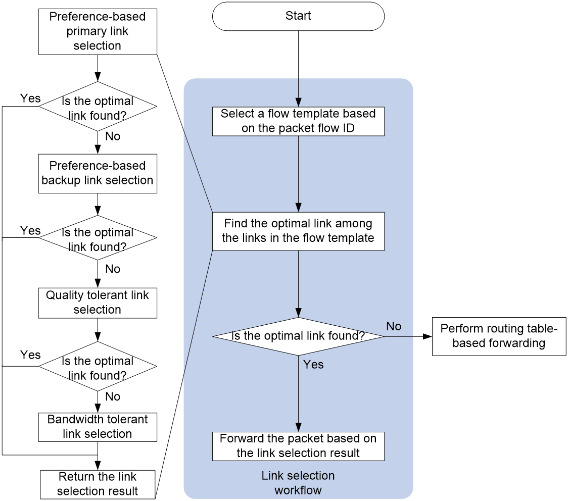
RIR uses the following workflow to select a link to forward a packet:
1. The device selects the service flow template based on the Flow ID carried by the packet.
2. In the link configured in the service flow template, select the optimal link, and then proceed step by step.
a. Preference-based link selection
b. Quality tolerant link selection
c. Bandwidth tolerant link selection
3. If the optimal link is found in any class of routing, return the routing result and stop the routing process for the remaining classes. Otherwise, proceed to the next class of routing. If no optimal link is found in all classes of routing, it is considered that there is no optimal link, and the routing result is returned.
4. The device decides how to forward service traffic based on the returned route selection result. If the optimal link is found, it selects this link for packet transmission; if not found, it carries out ordinary forwarding according to the original route table entry.
After the first route selection is completed, the subsequent traffic of the same service is forwarded according to the first route selection result.
Figure 30 RIR link selection workflow
Preference-based link selection
Intelligent route selection prioritizes service traffic by choosing links with both quality and bandwidth that meet the service requirements. This process is called link privilege level selection. The link privilege level selection process is shown in Figure 31. The device traverses all privilege levels under the service traffic template in descending order, and for the current privilege level:
1. The device will traverse all links under the privilege level, determining whether each link is part of the equal cost path.
¡ If the link is one of the equal cost paths, continue to determine whether this link is the primary link that meets both the bandwidth and quality requirements for the service. If it is, then include this link as an optional link for the current privilege level. If not, continue to ascertain if this link is a link that meets the bandwidth requirements.
- If so, include this link in the quality-just-acceptable optional links, and continue to evaluate other links under the current privilege level.
- If not, continue to evaluate other links under the current privilege level.
¡ Continue to judge the other links under the current privilege level if the link is not one of the equal cost paths.
2. Once all links under the current privilege level have been traversed, the device will validate how many optional links are available for service traffic under the current privilege level.
¡ If there is only one selectable link, directly select that link as the optimal link.
¡ If there are multiple optional links, one or more links are selected as the best links according to the link load sharing mode. In the per-flow link load sharing mode, only one link is selected as the optimal link; in the per-packet link load sharing mode, multiple links are selected as the best links.
¡ If there are no optional links available, continue to traverse the links under the next privilege level.
3. If there are no selectable links at all privilege levels, it is considered that link selection based on privilege level has not found the optimal link for this service traffic.
For guidelines on how to determine if the link quality meets the requirements, please refer to Quality evaluation mechanism and quality policy. For guidelines on how to determine if the link bandwidth meets the requirements, please refer to Bandwidth-based link selection policy.
Figure 31 Preference-based primary link selection workflow
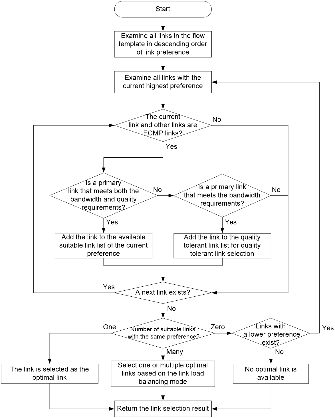
Quality tolerant link selection
When the device fails to find the optimal link during a privilege level selection, it reluctantly chooses a route based on quality.
In the process of selecting links according to their privilege level, all links that are available for quality-pushed selection are considered. These links do not meet the quality requirements for the service operations, but their bandwidth does. The quality-pushed selection is to reluctantly select a link with sufficient bandwidth for the service traffic when no link quality meets the service requirements.
When selecting links for service traffic based on quality, the link with the highest approximate CQI value in the potential links is first selected. If there are multiple optional links with the same approximate CQI value, one or more links will be chosen as the optimal link based on the link load sharing mode.
Bandwidth tolerant link selection
If a quality-reluctant path selection still does not find the optimal link, that is, the bandwidth of all equal cost path links does not meet the service requirements, the device will reluctantly select a bandwidth. Reluctant bandwidth selection will be among the links that are part of an equal cost path under the service traffic template, and reluctantly select a link for the service as the optimal link.
When selecting path for service traffic with constrained bandwidth, if there are multiple selectable links available, the device will select one or multiple links as the optimal link(s) based on the link load sharing mode.
Link selection delay and suppression
To improve the efficiency of packet forwarding, once the service traffic has completed its first intelligent route selection, all subsequent traffic of the same service follows the route selected the first time. However, if any link in the service flow template undergoes any of the following changes, the device will reselect the route:
· The link quality changes from meeting the service quality requirements to not meeting them, or from not meeting the service quality requirements to meeting them.
· The link has reached 90% of its maximum bandwidth usage, or the physical interface to which the link belongs has reached 90% of its maximum bandwidth usage.
To avoid frequent route selection by the device during link oscillation, RIR has defined both a delay time for route selection and a suppression period for route selection.
After a device executes a route selection, if a route selection suppression period is set, it will enter this period. During the route selection suppression period, the device will not reselect the route but will continuously maintain the link state data. After the suppression period ends, if the device's link state meets the condition for route reselection, and consistently meets this condition within the delay time after the period ends, the device will reselect the route after the delay time is exceeded. If the link state of the device changes to not meet the route reselection condition within the delay time, the device will not reselect the route.
SaaS path optimization
SaaS path optimization enables the device to select optimal paths for traffic that accesses SaaS applications and adjust the optimal paths accordingly when path quality changes.
SaaS applications
Introduction to SaaS applications
SaaS applications can be categorized as user-defined SaaS applications and predefined SaaS applications. The user-defined SaaS applications are generally commonly used, and are predefined by the system. On the other hand, predefined SaaS applications are configured by the user based on their actual requirements.
Access methods for SaaS applications
Devices can access SaaS applications in three ways: direct access, indirect access via a gateway, and a hybrid access mode.
Direct access
As shown in Figure 32, the device accesses the SaaS application directly through the local interface, and based on the quality of the path from local direct access to the SaaS application, it performs the optimization of the SaaS path.

Access through a gateway
As shown in Figure 33, the device operates as a client and accesses SaaS applications through a gateway. It performs SaaS path optimization based on quality information for the paths that can access SaaS applications via a gateway.
Figure 33 Access via a gateway
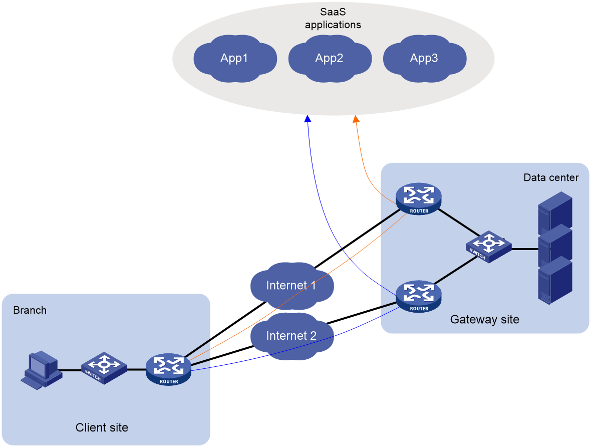
Hybrid access
In hybrid mode, the device can directly access SaaS applications or access them via a gateway. When optimizing the SaaS path, the device will select optimal paths based on the quality of the paths for direct and indirect access to the SaaS applications.
SaaS path quality probe and evaluation
SaaS path quality probe
Health check URL
When the device performs path optimization for a specified SaaS application, it will probe the quality of the path accessing the SaaS application via the health check URL. Based on the quality detection results, it will select the optimal path for the traffic visiting this SaaS application.
The health check URL of predefined SaaS applications is configured manually. The health check URL of user-defined SaaS applications is set by the system's default configuration, and cannot be modified.
Probe mechanism
The device directly accesses the SaaS application, or acts as a gateway device for other devices to access the SaaS application. It sniffs the quality of the path to the SaaS application through the health check URL every 30 seconds, using the interface manually configured for direct access to the SaaS application.
An indirect access path is composed of the SDWAN tunnel between the client and the gateway, and the gateway's path to the SaaS application. The device will use the quality probe mechanisms of the RIR-SDWAN service to measure the quality of the SDWAN tunnel, and collect the best path quality information for the gateway to access the SaaS application (as advertised by the gateway). This includes SaaS path quality information sent by the CPE in the gateway site via the BGP IPv4 Tnl-encap-ext route to the RR, which is then reflected to other CPEs. This information is used to determine the quality of the indirect access path.
SaaS path quality evaluation
CQI
When the device performs path optimization for a specified SaaS application, it sniffs the quality of the path accessing the SaaS application. Based on the probe results and the expected quality values (delay, jitter, and packet loss rate), it uses the CQI algorithm to evaluate the quality of the path.
The working mechanism of the CQI algorithm is as follows:
· When the detection result of a single quality metric (delay, jitter, or packet loss rate) meets the expected quality for accessing SaaS applications, the single CQI value is considered to be 100.
· When the result of a single quality probe does not meet the expected quality for accessing SaaS applications, the single CQI value (the latency CQI value Ds, the jitter CQI value Js, or the packet loss rate CQI value Ls) equals (expected quality value for the metric * 100) divided by the single quality probe result.
· The comprehensive quality (CQI) value equals to (x*Ds + y*Js + z*Ls) / (x + y + z). Here, x, y, and z respectively represent the weights of delay, delay jitter, and packet loss rate (with a numerical range from 0 to 10, and all cannot be zero).
Quality evaluation mechanism
To evaluate the quality of the path used by a device to access SaaS applications, it is first necessary to obtain the comprehensive quality value, known as the CQI.
· When assessing the quality of the path for a device directly accessing SaaS applications, the comprehensive path quality CQI value can be determined based on the path quality detected from the device's local interface.
· When evaluating the path quality of indirect access to SaaS applications between devices (access via gateway), the composite quality CQI value of direct access to the SaaS application from the gateway can be determined based on the path quality detected at the local gateway interface. Then, using the quality detection mechanism of RIR-SDWAN service, the composite quality CQI value of the path from the device to the gateway can be determined based on the detected SDWAN tunnel quality. The composite quality CQI value of the path for a device to access a SaaS application via a gateway is the average of the previous two values.
To avoid frequent link switchover, the device utilizes an approximate overall Composite Quality Index (CQI) value to evaluate link quality. The approximate overall CQI is the highest multiple of 5, not exceeding the overall CQI value. For instance, if the path's overall CQI value with indirect access to an SaaS application is 82.5, the approximate overall CQI value would be 80. Based on the approximate overall CQI value, the device allocates paths into different color areas.
· A path belongs to the green area if its approximate overall CQI value is in the range of 80 to 100.
· A path belongs to the yellow area if its approximate overall CQI value is in the range of 55 to 80.
· A path belongs to the red area if its approximate overall CQI value is in the range of 0 to 50.
CQI-based optimal path selection
The device first selects a color area in the order of green, yellow, and red. Then, it selects an optimal path in the selected color area. If the selected color area has only one path, this path is the optimal path. If the selected color area has multiple paths, the device randomly selects one of the paths as the optimal path.
SaaS path optimization mechanism
Accessing SaaS applications through dynamically allocated IP addresses
Users generally acquire the IP address of a SaaS application dynamically via DNS request based on the SaaS application's URL, in order to access the SaaS application. When a device receives a DNS request packet to access the SaaS application (the URL in the DNS request packet is the URL of the SaaS application instance), it will optimize the SaaS path in the following steps:
1. Select the optimal path for accessing SaaS applications based on the quality of the path evaluated by the CQI algorithm.
2. Forward the DNS request packet via the optimal path.
3. Associate the IP address in the received DNS response packet with the optimal path, and record it as an optimal path information entry.
4. Transmit the DNS response packet to the user.
5. The user accesses the SaaS application using the IP address from the DNS response packet.
6. After receiving the packet transmitted by the user, the device looks up the entry for the optimal path information based on the target IP address in the packet. This enables the packet to be forwarded to access the SaaS application via the recorded optimal path.
Accessing SaaS applications through static IP addresses
The system has predefined static IP addresses for user-defined SaaS applications. Users can use the static IP addresses when accessing the user-defined SaaS applications.
When a device receives a service packet with the static IP address of a user-defined SaaS application as the destination IP address, if there is no optimal path entry corresponding to this static IP address, it will select the optimal path for this service packet based on the path quality of the SaaS application that the static IP address belongs to, and associate the static IP address with the optimal path. This will be recorded as an optimal path entry. The device then forwards subsequent packets received with the static IP address as the destination IP address, according to the optimal path entry.
Aging of optimal path entries
Optimal path entries will expire after a period of time. The optimal path entries created for dynamic IP addresses will expire 2 minutes after the dynamic IP addresses resolved by DNS expire.
Typical network applications
Single-HQ flat network
As indicated in Figure 34, the headquarters communicates with the branches and amongst branches through SDWAN tunnels. In order to avoid the disruption of packet forwarding caused by a single point failure of CPE devices, the headquarters typically employs technologies like VRRP for the deployment of dual CPEs. Deploying CPE devices via a controller can simplify the challenges of network deployment. The SDWAN tunnels between sites support a variety of link types including MPLS L3VPN dedicated lines, MSTP, Internet, and 4G/5G.
Figure 34 Single-HQ flat network
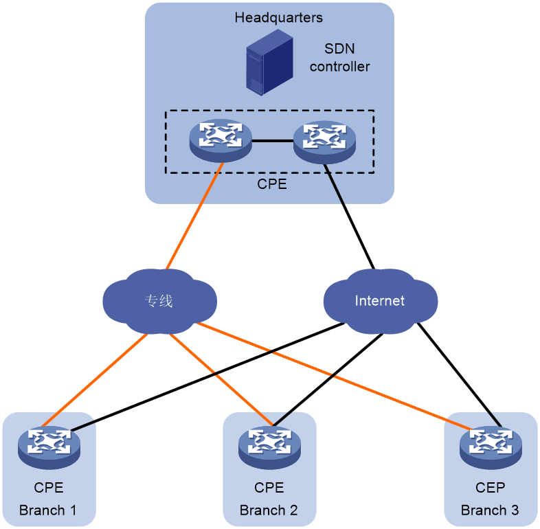
Multicenter flat network
As shown in Figure 35, in a multi-headquarters network, headquarters are interconnected with each other, and with branches, through SDWAN tunnels. To avoid packet forwarding interruptions caused by single-point failures of CPE devices, headquarters typically deploy dual CPEs using technologies like VRRP. The SDWAN tunnels between sites support a variety of link types, including MPLS L3VPN private lines, MSTP, Internet, and 4G/5G.
Figure 35 Multi-HQ flat network
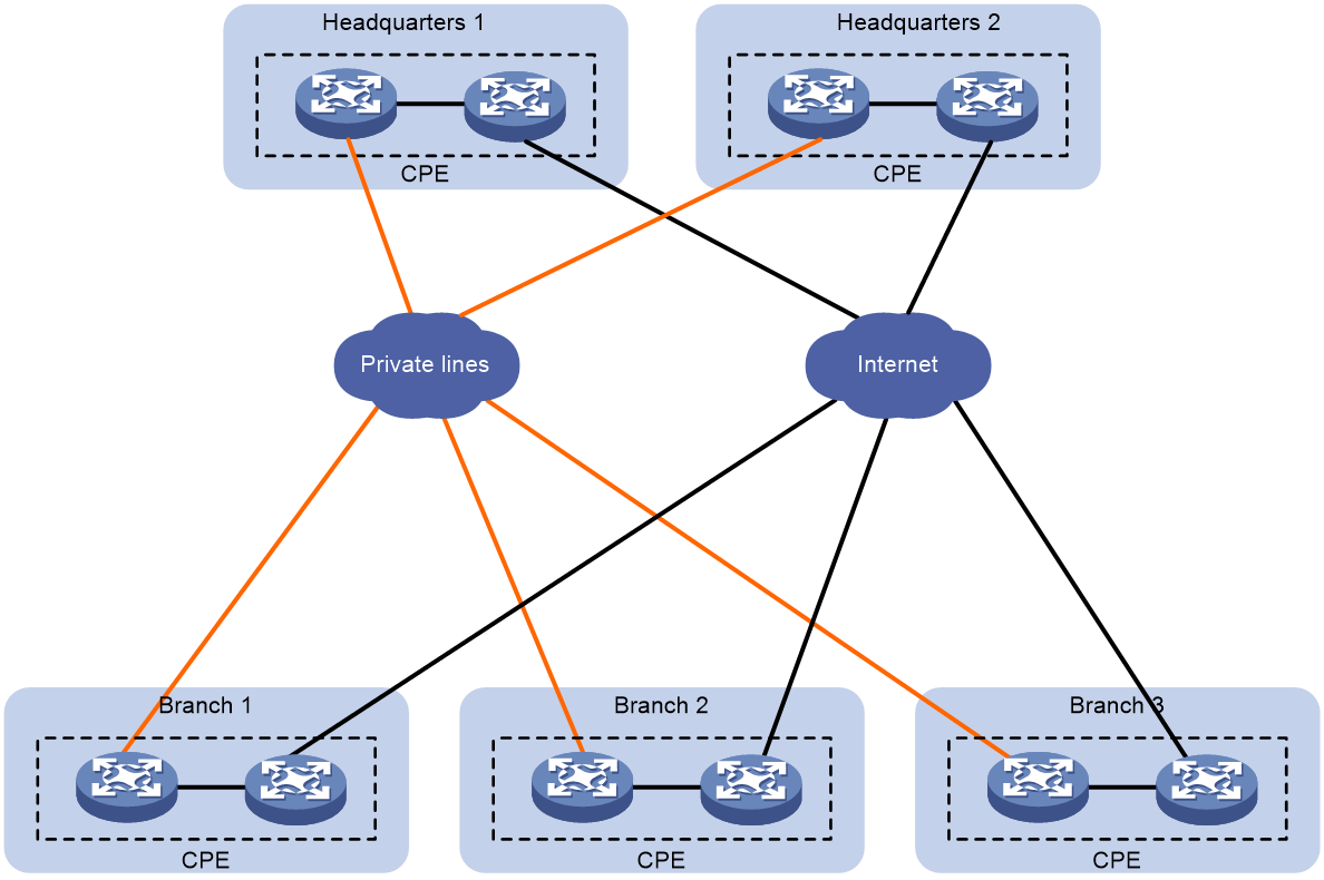
Tired networking
As shown in Figure 36, this type of network setup is generally used in scenarios involving regional distribution within large enterprise networks. Stratified networking that deploys private lines between branches and the distribution layer, as well as between the distribution layer and the headquarters, can save inter-provincial private line costs. SDWAN tunnels between sites support a rich variety of link types, including MPLS L3VPN dedicated lines, MSTP, Internet, and 4G/5G networks.
Figure 36 Layered Network Schematic Diagram.
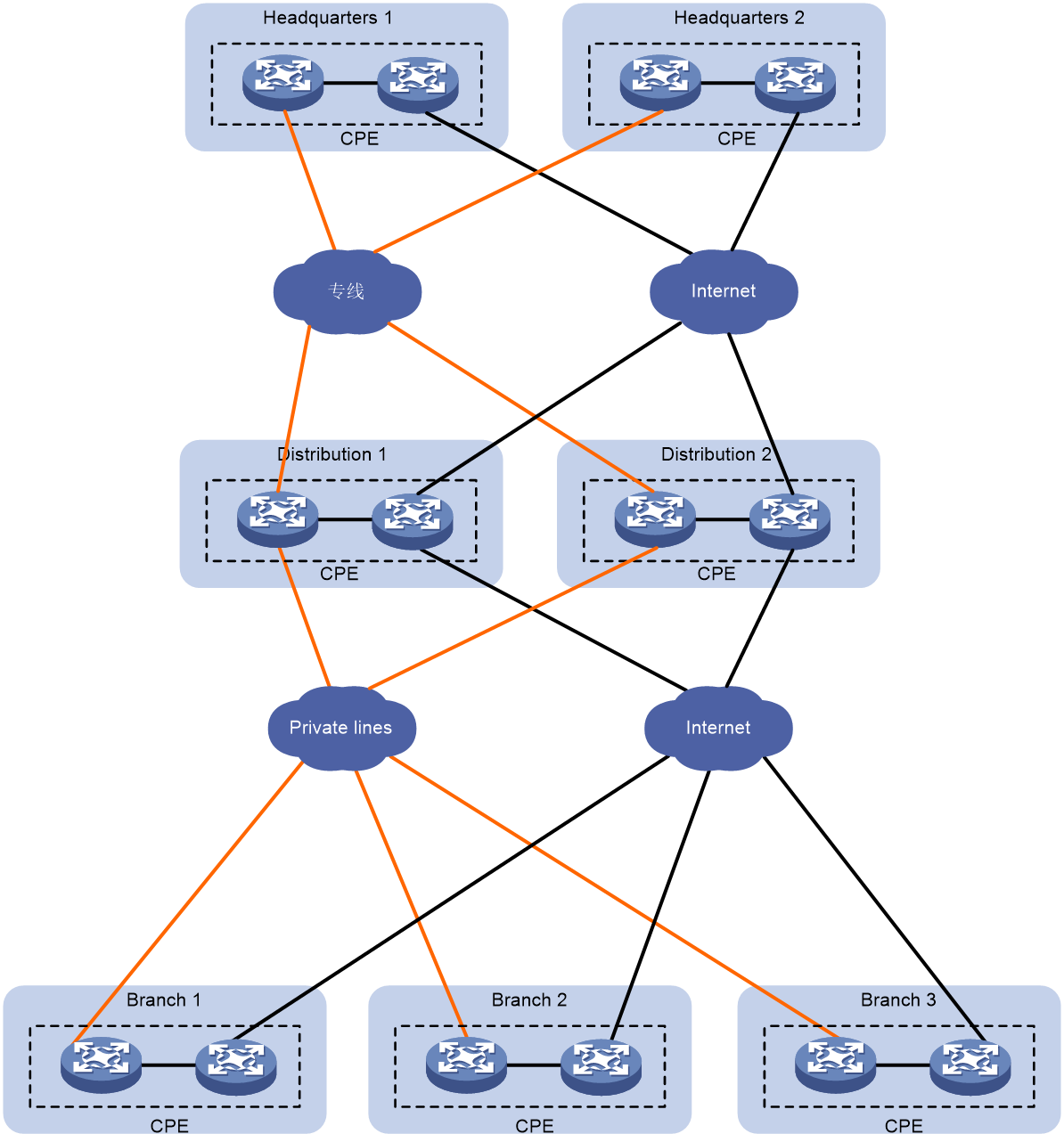
Cloud management network
As shown in Figure 37, this network configuration suits small and medium-sized carriers. The carrier provides SDWAN management services and leases customer site CPE devices, also offering a unified controller to deliver SDWAN services to multiple enterprises. As tenants, enterprises lease the SDWAN services offered by the carrier (purchased/leased device + SDWAN software). Enterprise tenants can manage all SDWAN operations within their corporate boundaries but won't have visibility into other tenants' operations.
Figure 37 Cloud Management Network
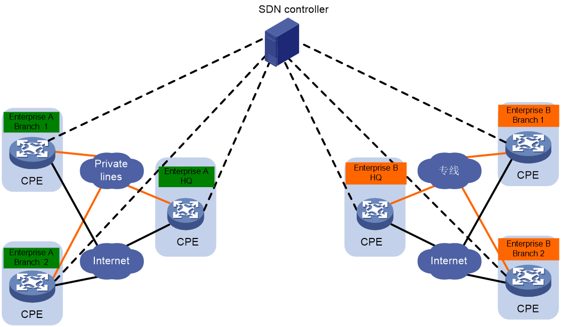
Carrier POP network
· In the backbone network of carriers/MSPs (Managed Service Providers), Point Of Presence (POP) network service points are deployed at the edge. SDWAN services are deployed within these POP points for enterprise site access. Gateways among POP points are interconnected based on the backbone network to form an overlay. POP points from different regions form a POP backbone network.
· By using the SDN controller and Internet links or local low-cost dedicated lines, SDWAN tunnels are deployed between the enterprise branch site CPE and the POP point gateway. This brings the traffic of enterprise branch sites into the carrier's POP network. With the aid of the interregional interconnected POP backbone network, high-quality, low-cost connectivity between interregional sites is achieved.
· Carriers enhance the quality of wide area network (WAN) and operation-level SDWAN services for users accessing across regions and countries, by integrating POP network with SDWAN technology. This new type of deployment is cost-effective, quickly deployed, and assured.
Figure 38 Carrier POP Network
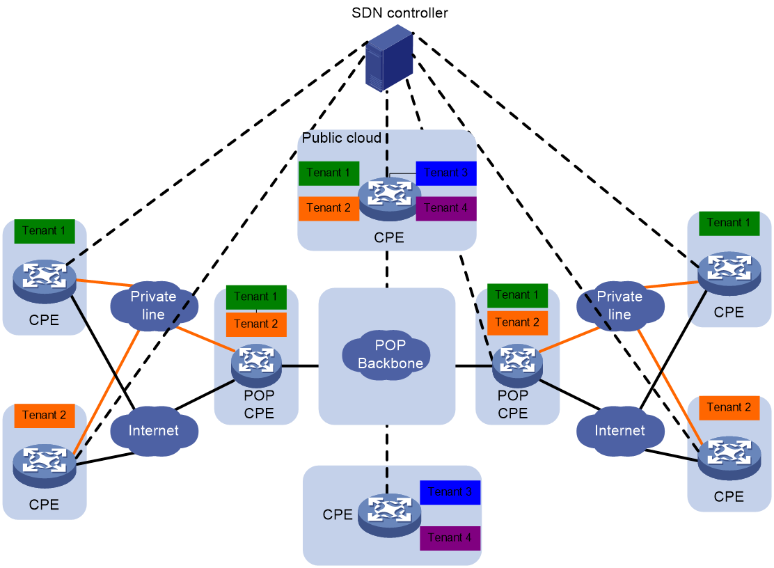
Carrier POP tiered networking
As shown in Figure 39, this network setup is generally used in scenarios for cross-national or cross-regional carrier Point of Presence (POP) networking. Carrier POPs are divided into different zones based on regions, and the gateways of POPs in different zones can only communicate with each other through dedicated zone intercommunication POP gateways.
Figure 39 Carrier POP tiered networking
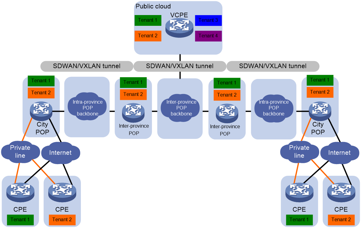
References
· RFC 7348 presents the Virtual eXtensible Local Area Network (VXLAN). It's a framework that allows the overlay of virtualized Layer 2 Networks on top of Layer 3 Networks.
· Source Text: RFC 4301: Security Architecture for the Internet Protocol.
· RFC 4303: IP Encapsulating Security Payload.
· RFC 4271 is related to the Border Gateway Protocol 4 (BGP-4).
· RFC 4760: Multiprotocol Extensions for BGP-4
· draft-dunbar-idr-sdwan-port-safi
· draft-ietf-idr-sdwan-edge-discovery/00
· draft-dunbar-bess-bgp-sdwan-usage
