- Released At: 08-05-2025
- Page Views:
- Downloads:
- Table of Contents
- Related Documents
-
IPv6+ Technology White Paper
Copyright © 2024 New H3C Technologies Co., Ltd. All rights reserved.
No part of this manual may be reproduced or transmitted in any form or by any means without prior written consent of New H3C Technologies Co., Ltd.
Except for the trademarks of New H3C Technologies Co., Ltd., any trademarks that may be mentioned in this document are the property of their respective owners.
This article contains general technical (Tech) information. Some information may not be applicable (NA) to the product you have purchased.
Overview
Technical background
The rapid development of emerging fields such as 5G, Internet of Things, and cloud computing has led to a drastic expansion in network size, increasing complexity, a richer variety of services, and growing demand for intelligence. This presents new challenges to network technology:
· Under the requirement for ubiquitous connectivity, networks must offer a vast address space to allocate a network address to each endpoint.
· The vast number of network connections and the massive traffic demand higher bandwidth, transmission, and bearer capability from the network.
· There are numerous types of services, each with diverse requirements, necessitating the provision of differentiated services for different businesses to achieve various levels of QoS assurance.
· The network must support intelligent connectivity and smart operations to meet the emerging requirements for intelligence.
The first-generation network layer protocol IPv4 has insufficient address space and cannot meet the requirements of the Internet of Things. The second-generation network layer protocol IPv6 (Internet Protocol Version 6) uses 128-bit IPv6 addresses, offering over 3.4×10^38 addresses. The main advantages of the IPv6 protocol include:
· IPv6 offers a sufficiently large address space to provide an IPv6 address for every device with Internet connectivity needs without worrying about address exhaustion, significantly enhancing Internet service capabilities.
· Endpoints can communicate end to end using their respective IPv6 addresses without the need for address translation, reducing network maintenance complexity and facilitating precise traffic monitoring and management.
· Compared to IPv4, IPv6 simplifies the packet header by eliminating the option field and introduces multiple extension headers. This enhances processing efficiency and greatly increases IPv6's flexibility and expansion capability.
IPv6 enables a broader range of connections for the Internet and the Internet of Things, serving as the foundation for connecting everything. Under the booming new business scenario, merely achieving interconnectivity of all things is far from sufficient. We must also consider requirements for business differentiation and intelligent operations and maintenance.
Therefore, IPv6+ innovates massively on the IPv6 protocol, introducing network technologies like SRv6, Network Slicing, in-situ Flow Information Telemetry (iFIT), novel multicast (BIER), service chaining (SRv6 SFC), Deterministic Network (DetNet), and Application Awareness Network (APN6), and enhances intelligent identification and control.
IPv6+ is an intelligent IP technology designed for the 5G and cloud era, featuring programmable paths, rapid service provision, automated operations and maintenance, quality visualization, SLA assurance, and application awareness. IPv6+ elevates the Internet of Things to intelligent interconnect of things, aiding the digital transformation of various industries.
Technical advantages
IPv6+ not only features the vast address space and flexible expansion of the IPv6 protocol, but it also enhances the capabilities of IP networks in the following areas:
· Broadband connection: Uses technologies like SRv6 to offer carrier and differentiated services for various applications, ensuring flexible network deployment and traffic scheduling to maximize user experience.
· Determinism: By integrating network slicing and DetNet technologies, IPv6+ provides users with a deterministic network where the quality of service is predictable.
· Low latency: Allocates resources appropriately to provide high speed data channels for services with high latency demands, ensuring latency stays within the required business parameters.
· Security: Quickly identifies security risks and implement protective measures to significantly enhance network security.
· Intelligence: Leverages artificial intelligence and iFIT to enable smart operations. It can automatically translate user intentions into network configuration requirements and predict, identify, locate, and resolve faults.
Development stages of IPv6+
The development of IPv6+ can be divided into three stages:
· IPv6+1.0: Offers network programming capabilities through SRv6, with primary features including SRv6 basic functionalities such as TE, VPN, and FRR.
· IPv6+2.0: Ensures user experience through technological innovation. The technical innovations of IPv6+2.0 include G-SRv6, network slicing, iFIT, BIER, SRv6 SFC (service function chaining), and DetNet.
· IPv6+3.0: Develops an Application-Driven Network (AD-NET). The primary feature is APN6. APN6 leverages the programmable path feature of IPv6 packets to carry application and user information (such as application IDs and network performance requirements) within the IPv6 packets. This enables the network to recognize applications and their needs, providing corresponding SLA assurances for differentiated services and intelligent traffic optimization.
Currently, Comware has fully implemented IPv6+1.0 and has realized most of the IPv6+2.0 technologies. More IPv6+ technologies are being progressively implemented.
Flexible extension headers
IPv6 expansion headers enhance the protocol's extensibility, facilitating technical and business innovation on the IPv6 framework. Some of the technological innovations of IPv6+ are based on IPv6 extension headers.
Format of IPv6 packets with extension headers
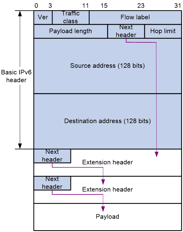
An IPv6 packet can carry zero, one or more extension headers. As shown in Figure 1, IPv6 uses the Next header field to identify the type of the next extension header. For example, a field value of 43 in the IPv6 basic packet header indicates that the next extension header is the routing header. A field value of 44 in the routing header indicates that the next extension header is the fragment header.
|
|
NOTE: The Next header field in the last extension header is used to identify the payload type. For example, a field value of 6 indicates that the payload is a TCP packet, and a field value of 17 indicates that the payload is a UDP packet. |
Figure 1 Format of IPv6 packets with extension headers
IPv6 extension header types
Table 1 displays extension headers supported by IPv6. Extension headers allow IPv6 to provide good scalability. According to service needs, you can define new IPv6 extension headers, or define new sub-extension headers for existing extension headers.
Table 1 IPv6 extension headers
|
Extension header name |
Type value |
Node for header processing |
Description |
Application |
|
Hop-by-Hop Options Header |
0 |
All nodes along the packet forwarding path |
Used for jumbo load alerts, router alerts, and Resource Reservation Protocol (RSVP). |
Network slicing |
|
Routing Header |
43 |
Destination node and intermediate nodes through which packets must pass |
Used to specify intermediate nodes through which packets must pass. |
SRv6 |
|
Fragment Header |
44 |
Destination node |
When the length of an IPv6 packet exceeds the Path MTU (PMTU) of the packet forwarding path, the source node fragments the IPv6 packet and fills in fragment information in the fragment header. In an IPv6 network, only the source node can fragment packets. The intermediate nodes cannot perform packet fragmentation. NOTE: The PMTU is the minimum MTU on the packet forwarding path from the source node to the destination node. |
N/A |
|
Encapsulating Security Payload Header (ESP Header) |
50 |
Destination node |
Used to provide data encryption, data source authentication, data integrity verification, and anti-replay. |
IPsec |
|
Authentication Header |
51 |
Destination node |
Used to provide data source authentication, data integrity verification, and anti-replay. It can protect packets from tampering but cannot prevent packet eavesdropping. It is suitable for transmitting non-confidential data. AH provides better authentication service than ESP. |
IPsec |
|
Destination Options Header |
60 |
Destination node and intermediate nodes specified in the routing header |
Used to carry information sent to the destination node and intermediate nodes specified in the routing header. For example, in mobility IPv6, the destination options header can be used to exchange registration information between mobile node and home agent. |
BIER and iFIT |
Key technologies of IPv6+
Currently, the IPv6+ network technologies that Comware supports include SRv6, G-SRv6, Network Slicing, iFIT, BIER, and SRv6 SFC.
SRv6
SRv6
Segment Routing IPv6 (SRv6) is a carrier technology for the next generation network. Based on IPv6 and source routing, this technology simplifies the traditional complex network protocol and provides application-level SLA assurance. It establishes the foundation for network automation by using IPv6 extension headers to enable flexible orchestration of network paths.
SRv6 has strong network programmability, and it is the basis of network automation. This technology can unify the data plane of network slices, which not only has the flexibility and strong programmability of IPv6, but also provides strong support for intelligent IP network slicing, DetNet, and SFC.
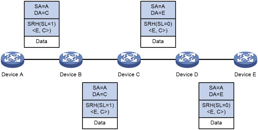
SRv6 applies Segment Routing to an IPv6 network and uses IPv6 addresses as SIDs. SRv6 nodes forward packets according to the SID list encapsulated in the Segment Routing Header (SRH) of IPv6 packets. The SID list controls the packet forwarding path. Figure 2 shows the forwarding process of SRv6 packets.
Figure 2 SRv6-based packet forwarding
For more information about SRv6, see SRv6 Technology White Paper, SRv6 TE Policy Technology White Paper, SRv6 High Availability Technology White Paper, and SRv6 VPN Technology White Paper.
Benefits
SRv6 provides the following benefits:
· Simplified maintenance—You only need to control and maintain path information on the source node. Path maintenance is not required on other nodes.
· Intelligent control—Designed based on SDN architecture, SRv6 perfectly integrates applications and networks, which is a superb application driven network solution. All SRv6 forwarding paths, forwarding behaviors, and service types are controllable.
· Simple deployment—By extending IGP and BGP, SRv6 does not require MPLS labels. You do not need to deploy label distribution protocols. The SRv6 configuration is simple.
In an SRv6 network, you do not need to upgrade network devices in a large scale to deploy new services. In a data center or WAN, you only need to ensure that the network edge devices and specific network nodes support SRv6 and other devices support IPv6.
· Adaptable to 5G service requirements—With the development of 5G services, IPv4 addresses can no longer meet the network requirements of operators. To meet 5G service requirements, deploy SRv6 in the operator networks to configure all devices to forward traffic based on IPv6 addresses.
· Good scalability—SRv6 defines multiple types of SIDs. They have different functions and instruct different forwarding actions. You can use different types of SIDs to implement different VPN services. In addition, new types of SIDs can be defined as needed to meet new service requirements.
SRv6 packet forwarding modes
SRv6 supports the following forwarding modes:
· SRv6 BE—In this mode, an SRv6 node uses an IGP to advertise a locator segment. The nodes in the SRv6 network calculate the optimal route to the locator segment according to the shortest path first algorithm. The path of the optimal route is called an SRv6 BE path. When the BGP routes in the public network or a VPN instance are recursed to the SRv6 BE path on an SRv6 node, the SRv6 node can steer the public network traffic or VPN traffic to the SRv6 BE path.
· SRv6 TE—In this mode, the ingress node uses different methods to steer public network traffic or VPN traffic to the forwarding path of an SRv6 TE policy. The forwarding path of the SRv6 TE policy is called an SRv6 TE path.
SRv6 high availability
To ensure service traffic stability in an SDWAN network, SRv6 provides high availability measures to avoid long-time service interruption and improve network quality.
SRv6 provides the following features to ensure network high availability:
· Topology-Independent Loop-free Alternate FRR (TI-LFA FRR)—Has FRR protection capability with high protection rate. TI-LFA FRR supports arbitrary topology protection in principle, which can make up for the shortcomings of traditional tunnel protection technologies.
· SRv6 microloop avoidance—Eliminates loops caused by disorder convergence of IGP in a full-mesh network. This feature provides microloop avoidance after both a network failure and a failure recovery to resolve issues caused by microloops, for example, network packet loss, link latency and jitter, and packet disorder.
· Transit node protection—Resolves the issue of TI-LFA FRR protection failure caused by strict node constraint in an SRv6 TE policy scenario.
· Tail node protection—Resolves the packet forwarding failure issue caused by single point of failure occurred on the SRv6 TE policy tail node in a dual-homing protection scenario.
SRv6 VPN
Traditionally, to deploy a VPN network, you need to set up a virtual private communication network over the public network by configuring LDP, RSVP-TE, or other label distribution protocols. The deployment by using this method is complex and the maintenance cost is also high. To resolve the issues, you can deploy SRv6 VPN over the public network.
SRv6 VPN uses SRv6 tunnels to carry VPN services over an IPv6 network. This VPN technology uses MP-BGP to advertise VPN routing information on the control plane and uses SRv6 encapsulation on the data plane. SRv6 VPN can provide Layer 2 and Layer 3 connectivity for geographically dispersed sites of a tenant based on the existing service provider or enterprise IP network.
The following SRv6 VPN solutions are available:
· L3VPN solutions—Include IP L3VPN over SRv6 and EVPN L3VPN over SRv6.
· L2VPN solutions—Include EVPN VPWS over SRv6 and EVPN VPLS over SRv6.
G-SRv6
In an SRv6 TE policy scenario, the administrator needs to add the 128-bit SRv6 SIDs of SRv6 nodes on the packet forwarding path into the SID list of the SRv6 TE policy. If the packet forwarding path is long, a large number of SRv6 SIDs will be added to the SID list of the SRv6 TE policy. This greatly increases the size of the SRv6 packet header, resulting in low device forwarding efficiency and reduced chip processing speed. The situation might be worse in a scenario that spans across multiple ASs where a much greater number of end-to-end SRv6 SIDs exist.
Generalized SRv6 (G-SRv6) encapsulates shorter SRv6 SIDs (G-SIDs) in the segment list of SRH by compressing the 128-bit SRv6 SIDs. This reduces the size of the SRv6 packet header and improves the efficiency for forwarding SRv6 packets. In addition, G-SRv6 supports both 128-bit SRv6 SIDs and 32-bit G-SIDs in a segment list.
For more information on G-SRv6, see SRv6 Technology White Paper.
Network slicing
Overview
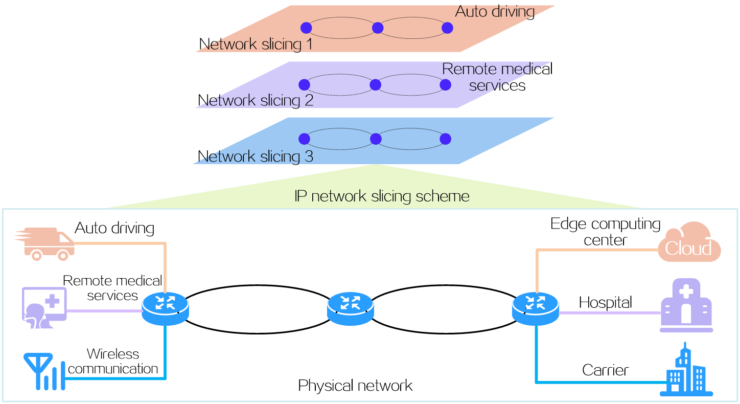
Network slicing is a method of creating multiple logical networks (network slices) for specific services or users over a common physical network. Each network slice has its own network topology, service level agreement (SLA) demand, and security and HA requirements. With network slices, service providers can fully use the existing network infrastructure and resources to provide differentiated network services for businesses, industries, or users.
Figure 3 Network slicing
Benefits
Network slicing brings the following benefits:
· Differentiated LSA—Carriers or large-scale enterprises provide all their services on the same network, but emerging new services demand different LSAs. For example, auto pilot requires highly on latency and jitter but has no big demand on bandwidth, while VR and high-definition video services have great demand on network bandwidth but no special requirements on latency. A traditional physical network cannot meet differentiated SLA demands, while building independent private networks costs too much. The network slicing solution well solves this issue. It deploys different network slices on the existing physical network for different services as needed.
· Network resource isolation—Some industry customers need secure, reliable, and exclusive network resources. The carrier also wants to provide separated services for different customers so as to prevent general customers from occupying network resources and ensure good user experience for premium customers. The network slicing solution can allocate different resources to different users at the data plane, control plane, and management plane.
· Flexible topology—The development of unified cloud and network technology allows VMs migrate across data centers. Network connection relationship becomes more flexible and complicated. The network slicing solution can use the Flex-Algo technology to meet the requirements of flexible and dynamic changes of network topologies.
Network slicing solution
Network slicing is a solution that uses multiple network technologies to implement logical network creation, resource isolation, differentiated LSA, and flexible topology on a physical network. The network slicing technologies include (but not limited to) the technologies listed in Table 2.
Table 2 Network slicing technology
|
Technology name |
Implementation layer |
Description |
Application |
|
MDC |
Management plane Control plane Data plane |
A physical device is virtualized into multiple logical devices called multitenant device contexts (MDCs). Each MDC is assigned separate hardware and software resources, and operates independently. For users, a MDC is an independent physical device. MDCs are highly secure, as they are isolated from each other and cannot communicate with each other directly. |
Applicable to both IPv4 and IPv6 networks |
|
Flex-Algo |
Control plane |
The Flexible Algorithm (Flex-Algo) is a flexible, IGP-based algorithm that allows users to define the metric type for the IGP path calculation, such as cost, link latency, or TE metric, and uses the SPF algorithm to calculate the shortest path to reach the destination address. When calculating the shortest path, Flex-Algo also supports using the link affinity attributes and Shared Risk Link Group (SRLG) as constraints to specify the ultimate topology to include or exclude specific links. Therefore, network elements that participate in different Flex-Algo calculations can form different logical topologies. By deploying multiple Flex-Algo algorithms on a physical network, the network can be divided into multiple separated network slices. |
Applicable to SRv6 and SR-MPLS networks |
|
FlexE |
Data plane |
The Flex Ethernet (FlexE) technology decouples Ethernet MAC rate and PHY rate of a high-speed Ethernet interface to implement flexible control of the interface rate. FlexE uses one or multiple IEEE 802.3 high-speed physical interfaces to gain a high total bandwidth, and then flexibly assigns bandwidth to each FlexE logical interface according to the bandwidth requirement of the service on the local interface. The FlexE logical interfaces then can forward data for network slices. |
Applicable to both IPv4 and IPv6 networks |
|
Subinterface channelization |
Data plane |
Subinterface channelization (or subinterface slicing), is a granular network slicing technique that slices a high-speed interface into low-bandwidth subinterfaces called channelized (or sliced) subinterfaces. Each channelized subinterface is assigned a portion of bandwidth for exclusive use. The channelized subinterfaces use their exclusive bandwidths and scheduling queues to forward data, implementing independent data forwarding. |
Applicable to both IPv4 and IPv6 networks |
|
Slice ID |
Data plane |
Slice ID-based network slicing is a technique used in SRv6 networks. It uses a slice ID to uniquely identify a network slice. A service packet forwarded on a sliced network carries a slice ID. The device that receives the packet first searches the FIB for the outgoing interface, and then forwards the packet through the network slice channel that matches the packet's slice ID on the output interface. |
Applicable to SRv6 networks |
The slice ID based network slicing solution is recommended as it supports a large number (thousand-level) of slices, features simple configuration, and requires less SRv6 SIDs for a forwarding interface (all network slices only need a set of SRv6 locator resources). The following uses the slice ID based network slicing solution as an example to describe the fundamentals of network slicing.
iFIT
Overview
In-situ Flow Information Telemetry (iFIT) determines network performance by measuring the packet loss and packet delay of service packets transmitted on an SRv6, G-SRv6, or G-BIER network. iFIT is easy to deploy and can assess network performance accurately. The measurement results of iFIT can be reported to NQA via gRPC for network visualization management.
For more information about iFIT, see iFIT Technology White Paper.
Benefits
iFIT has the following advantages over traditional packet loss measurement technologies:
· Accurate measurement of network quality—iFIT directly measures the packet loss and packet delay of real service packets, and thus the measurement result reflects the real network condition.
· Easy deployment—Midstream devices and downstream devices can use iFIT packets to generate measurement information.
· Fast fault locating—iFIT provides flow-based measurement capabilities to achieve real-time monitoring of packet delay and packet loss on a per flow basis.
· Performance data visualization—iFIT displays performance data with a visualized UI and therefore allows fast fault detection.
· Path auto-discovery—Once the ingress point adds iFIT headers to the packets of a user service, the downstream device can identify these packets by their iFIT headers and generate measurement information. The analyzer uses this information to learn the real forwarding path of these packets.
· High extensibility—iFIT is hardware-based and has a small impact on the network.
Application scenarios
iFIT supports both end-to-end measurement and hop-by-hop measurement. These measurement methods are applicable to different networks.
End-to-end measurement
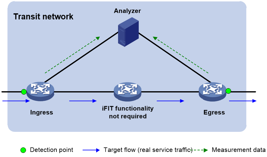
To measure the packet loss and packet delay on the entire network, use end-to-end measurement. As shown in Figure 4, iFIT measures whether packet loss or packet delay occurs between the ingress point (where the target flow enters the IP network) and the egress point (where the flow leaves the network).
Figure 4 End-to-end measurement
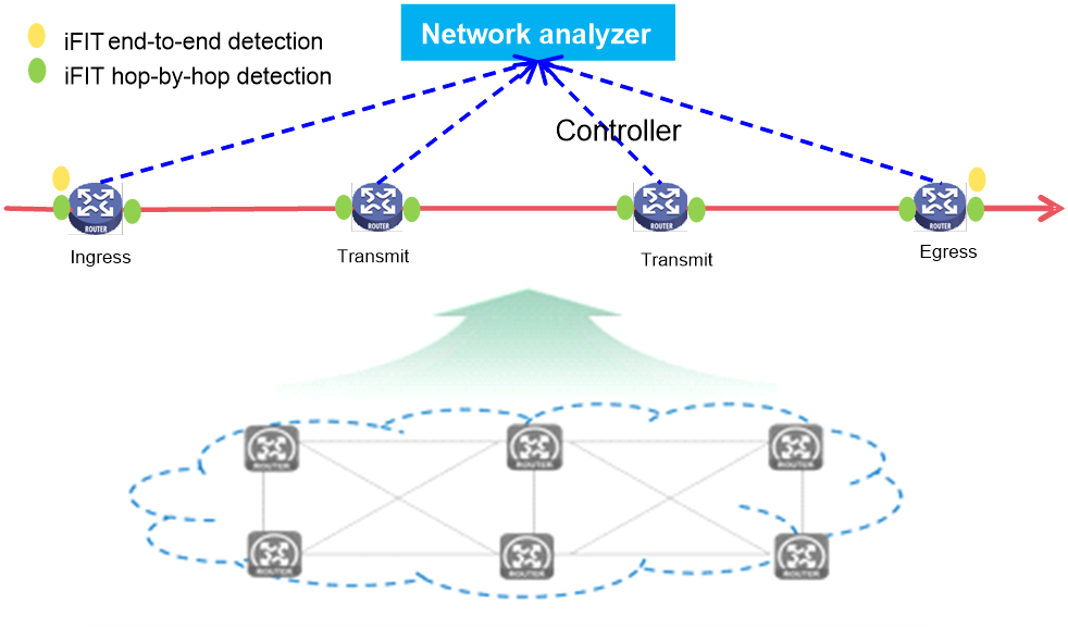
Hop-by-hop measurement
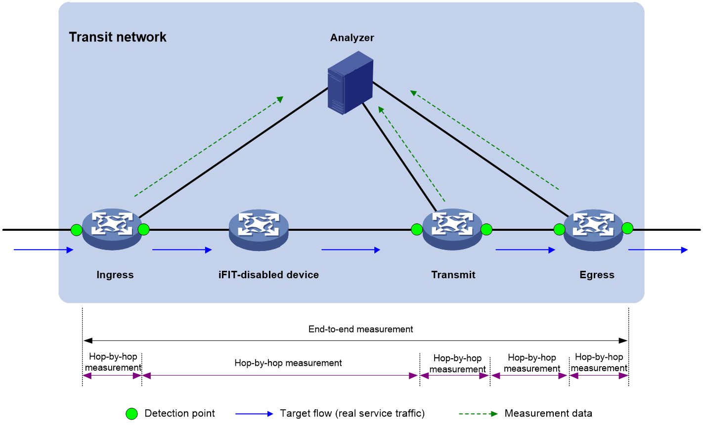
To accurately measure the packet loss and packet delay of each network node, use hop-by-hop measurement. To locate a faulty node, you can divide an end-to-end network into smaller measurement spans. As shown in Figure 5, iFIT measures whether the packet loss and packet delay occurs between the ingress point and egress point, ingress point and transmit point, transmit point and egress point.
Figure 5 Hop-by-hop measurement
BIER
Overview
Bit Index Explicit Replication (BIER) is a new architecture for the forwarding of multicast data packets. BIER encapsulates the destination nodes of multicast packets in a bit string. It does not require a protocol for explicitly building multicast distribution trees, nor does it require intermediate nodes to maintain any per-flow state.
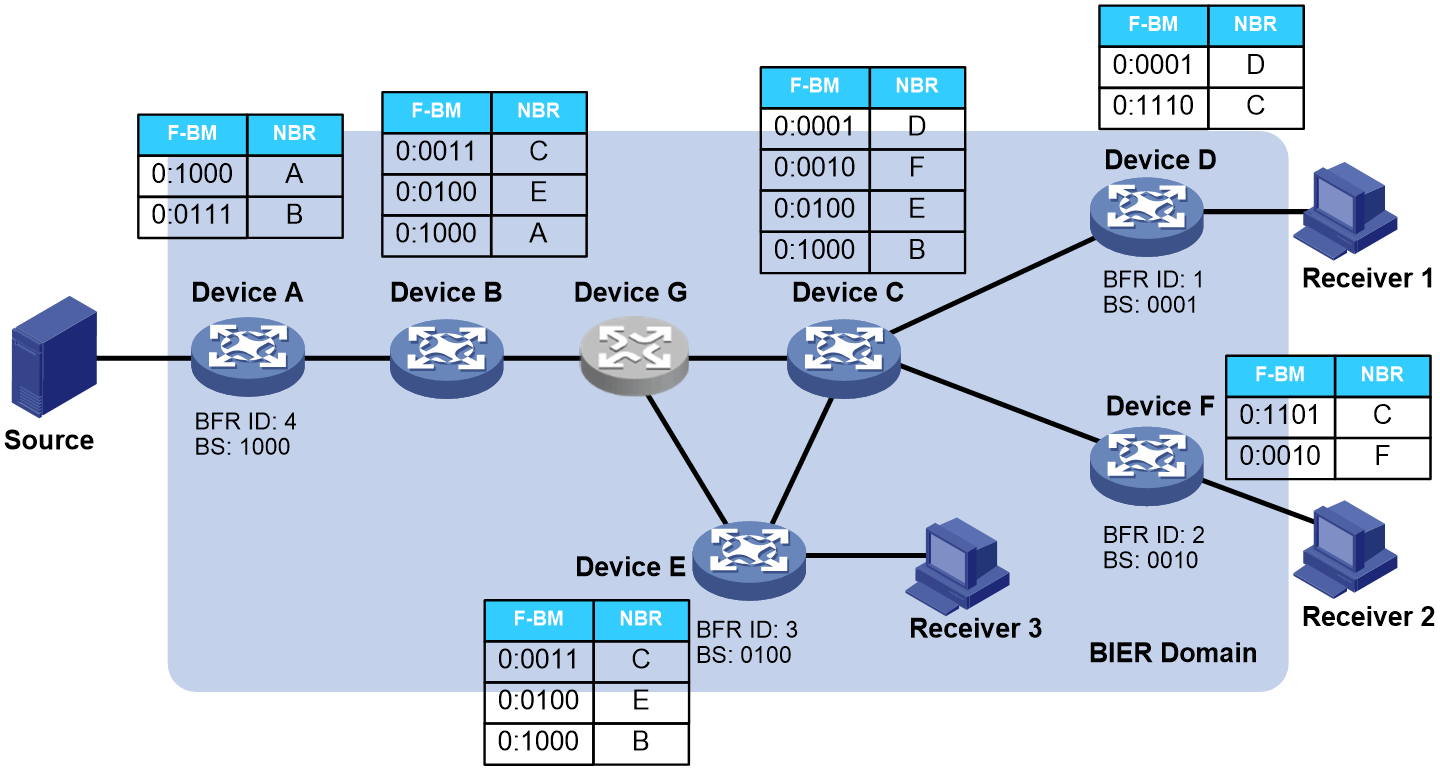
In a BIER network, multicast packets are forwarded according to the Bit Index Forwarding Table (BIFT) on the Bit-Forwarding Router (BFR).
Figure 6 BIER network
Currently, Comware supports two encapsulation types: Generalized BIER (G-BIER) and Bit Index Explicit Replication IPv6 Encapsulation (BIERv6).
For more information about BIER, see BIER Technology White Paper.
Benefits
BIER has the following benefits:
· Good multicast service scalability
The BIFT established on a BFR is a common forwarding table independent of multicast services. Intermediate nodes do not need to maintain any per-flow state. Both public multicast packets and private multicast packets can be forwarded according to the BIFT.
· Simplified service deployment and maintenance
Intermediate nodes are not aware of multicast services. Deployment of multicast services does not involve intermediate nodes. Changes to multicast services do not affect intermediate nodes.
· Simplified control plane
Intermediate nodes in the network do not need to run PIM. The control plane protocols are IGP and BGP.
· Easy evolution to SDN
Deployment of multicast services does not involve intermediate nodes. BIER encapsulation is added to packets on the ingress node to guide the replication of multicast packets. The BIER encapsulation carries a bit string identifying the output interface for multicast packets. Intermediate nodes replicate and forward multicast packets according to the bit string.
SRv6 SFC
To meet user requirements for business security and stability, datagrams often pass through various service nodes in sequence according to business logic during forwarding. These nodes include firewalls, intrusion prevention systems (IPS), and application accelerators. SRv6 SFC (Service Function Chain) guides packets along a specified path by inserting SRv6 path information into the original messages, allowing traffic to sequentially pass through application layer service devices for security control, application acceleration, and other processing tasks.
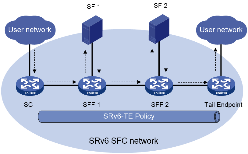
A typical SRv6 SFC network setup is shown in Figure 7. Service data enters the SRv6 SFC network from the customer network through the SC (Service Classifier). The SFF (Service Function Forwarder) then forwards the packets to each SF (Service Function) in sequence based on the SRv6 path information in the packets for processing. Finally, the data is forwarded back to the customer network from the egress node.
SRv6 SFC technology offers the following advantages:
· Flexible network orchestration
SRv6 SFC is based on SDN, bridging the gap between applications and networks and thus enabling better implementation of Application-Driven Networking (AD-NET). To deploy different services or adjust them, simply change the order of the service chain without altering the network element configuration to enable flexible activation and rapid deployment of network services.
· Network programmability
SRv6 SFC uses various types of SRv6 SIDs to indicate different forwarding actions. Pass different SIDs to meet various business scenario requirements. You can also define new SID types as needed, offering great scalability.
For more information about SRv6 SFC, see SRv6 SFC Technology White Paper.
Typical IPv6+ networkings
SRv6 application
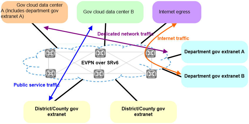
The deployment scheme for SRv6 in the external e-government network is shown as Figure 8.
· Internet access traffic is carried through EVPN over SRv6, assigning corresponding VPN permissions to Internet users, and carrying traffic through SRv6 tunnels.
· Public service traffic can use public addresses and be carried directly through SRv6.
· Special network traffic is divided into corresponding EVPN to ensure the network is dedicated and service logic is isolated.
· All paths can be dynamically adjusted by the SDN controller to ensure optimal resource usage.
Figure 8 SRv6 application in the external network of e-government
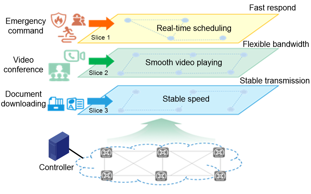
Network slicing application
The deployment scheme for network slicing in the e-government extranet is shown in Figure 9.
· By using various network slicing technologies, the backbone network bandwidth is refined to form multiple channels.
· According to different service needs (latency/jitter/packet loss), different strategies are distributed through the controller to achieve diversified utilization of channels.
· Different bandwidths can be allocated to different private networks (such as emergency command networks, video conference networks, document downloading networks) according to their requirements, ensuring that the traffic of one network will not be dropped due to congestion from another network in the same topology.
· According to customer's service requirements, the SRv6 forwarding path can be flexibly arranged to enhance network intelligence.
Figure 9 Network slicing application of the e-government external network
Visualization application
The deployment plan for the visualized e-government extranet is shown as follows in Figure 10. The visualization solution based on iFIT and Telemetry technology enables the following:
· Quality visibility and planning support: Periodic data collection generates real-time report data, providing data support for capacity expansion and subsequent planning.
· Move with demand and intelligent O&M: Achieve intelligent optimization of network paths based on current network service status, ensuring the quality of critical service operations.
· Accurate positioning and fast troubleshooting: When service issues occur, problems can be quickly identified and resolved through the graphical display on the network analyzer.
|
|
NOTE: For more information about Telemetry, see Telemetry Technology White Paper. |
Figure 10 Visualization application of e-government external network
References
· Expert Committee of Promoting Large-Scale IPv6 Deployment "IPv6+ Technical Innovation Vision and Prospects"
· Whu Hequan. "IPv6+ Empowers Intelligent Cloud Networks, Promoting Industry Digital Transformation." C114 Communication Network. 2021-03-05.