- Released At: 18-12-2024
- Page Views:
- Downloads:
- Table of Contents
- Related Documents
-
SRv6 TE Policy Technology White Paper
Copyright © 2024 New H3C Technologies Co., Ltd. All rights reserved.
No part of this manual may be reproduced or transmitted in any form or by any means without prior written consent of New H3C Technologies Co., Ltd.
Except for the trademarks of New H3C Technologies Co., Ltd., any trademarks that may be mentioned in this document are the property of their respective owners.
The content in this article is general technical information, and some information may not be applicable to the products you have purchased.
Contents
Concept of the SRv6 TE Policy group
Create an SRv6 TE policy group
Basic working principle of SRv6 TE policy
Deploy SRv6 TE Policy statically
Create SRv6 TE Policy automatically using ODN
Controller issues an SRv6 TE policy
Learn SRv6 TE Policy via PCEP protocol
Create the segment list manually
Establish a segment list using a dynamically computed path
SRv6 TE Policy diverts traffic
802.1p-based traffic direction
Based on service-class traffic diversion
Diverging based on TE class ID
Based on APN ID for traffic diversion
Based on static route diversion
Draining based on policy routing
Choose SRv6 Traffic Engineering Policy Routing
SRv6 TE Policy Data encapsulation and forwarding
Expanded working principle of SRv6 TE Policy
Determine the validity of the SRv6 TE Policy
High availability (HA) of SRv6 TE Policy
SRv6 TE Policy is linked with echo BFD
The SRv6 TE Policy is linked with SBFD
BFD detects the specified return path of the SRv6 TE Policy
The hot spare function of the SRv6 TE Policy
The intelligent policy routing function of SRv6 TE Policy
Introduction to the Intelligent Policy Routing Function of SRv6 TE Policy
The intelligent policy routing mechanism of SRv6 TE Policy
Application scenario of SRv6 TE Policy
SRv6 Traffic Engineering Policy NLRI
TE Policy NLRI of BGP-LS route
Overview
Technical background
SRv6 TE Policy is a traffic engineering (TE) solution based on SRv6, providing users with functions such as path selection, path switchover, and backup protection during the traffic forwarding process. Similar to MPLS TE technical (Tech), SRv6 TE Policy can also be considered a new type of traffic engineered tunnel technology developed on the foundation of SRv6.
The SRv6 TE Policy provides a flexible method for selecting forwarding paths, satisfying different user requirements for forwarding. When multiple paths exist between the source node and destination node in a Segment Routing network, the sensible use of SRv6 TE Policy to select forwarding paths not only facilitates the administrator in network management and planning, but also effectively alleviates the forwarding pressure on network equipment.
Technical advantages
The SRv6 TE Policy technology has the following advantages:
· High availability (HA)
It supports the connectivity detection of SRv6 TE Policy through SBFD, enabling rapid fault pinpointing. It also supports hot spare functionality, effectively reducing packet loss during network outage.
· Diversifying the drainage.
The SRv6 TE Policy supports various traffic steering methods such as BSID-based, Color-based, and DSCP-based. You can flexibly select the traffic steering method based on different forwarding requirements.
· Flexible deployment
SRv6 TE Policy supports deployment in various network environments, such as IP L3VPN over SRv6, EVPN VPLS over SRv6, etc.
Basic concept
SRv6 TE policy
The SRv6 TE Policy is identified by the triplet {Headend, Color, Endpoint}.
· Source Node: The source node introduces the message into the SRv6 TE Policy. The SRv6 TE Policy then guides the message to be forwarded along the selected path.
· Color: The 'color' property of the forwarding path is used to distinguish multiple SRv6 TE Policies between the same source and destination node. The 'color' property can represent different quality requirements, such as low latency and high bandwidth.
· Endpoint: The IPv6 address of the destination node in SRv6 TE Policy.
Composition of SRv6 TE policy
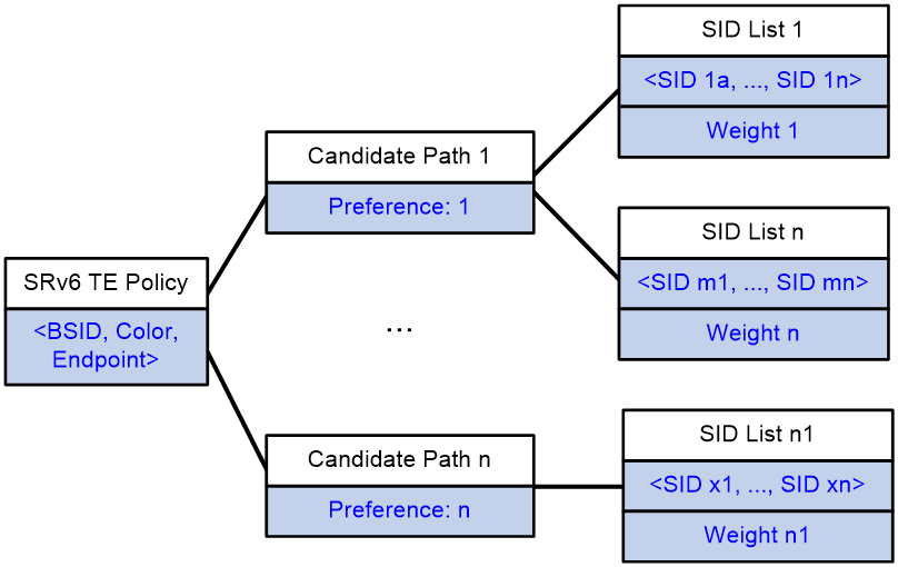
As shown in Figure 1, an SRv6 TE Policy consists of a BSID and multiple Candidate Paths with different privilege levels. Each Candidate Path includes one or more forwarding paths identified by a Segment List (SID list).
· BSID
Binding SID is associated with SRv6 TE Policy. If the destination address of the message is BSID, the traffic is directed to the SRv6 TE Policy associated with that BSID.
· Candidate Path
An SRv6 TE Policy includes one or more candidate paths, each having a different privilege level. When traffic is forwarded through an SRv6 TE Policy, the device selects the path with the highest privilege level from multiple candidate paths as the traffic forwarding path.
· SID List
The SID list contains information on the packet forwarding path and is composed of the SID (IPv6 address) of each node on the forwarding path.
The candidate path is made up of a SID list OR multiple weighted SID lists. After a SRv6 TE Policy selects a candidate path, it performs load sharing among multiple SID lists of the candidate path according to the weight of the SID list.
Figure 1 Composition of the SRv6 TE policy
SRv6 TE policy group
Concept of the SRv6 TE Policy group
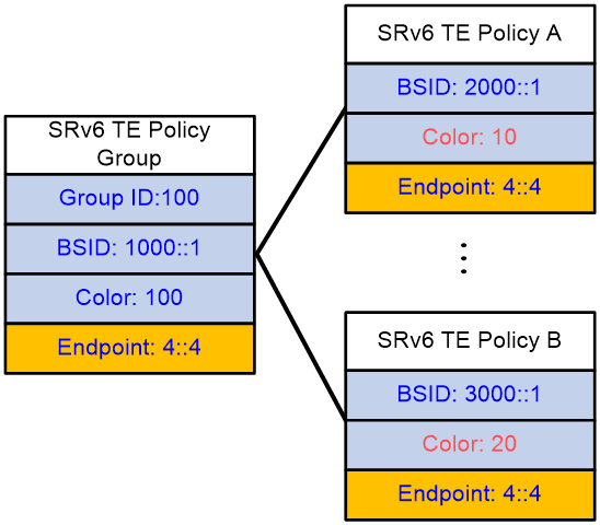
The SRv6 TE Policy group is a collection of SRv6 TE Policies with the same Endpoint. The traffic passed through the SRv6 TE Policy group can be mapped to the SRv6 TE Policies with different Color values within the group, based on the identification information such as DSCP or Dot1p values. This allows for differentiated control of forwarding according to the varying identification information of the business.
The SRv6 TE Policy group, identified by a Group ID, also has the properties of BSID, Color, and Endpoint.
· The extended community attribute carried by the SRv6 TE Policy group is 'Color'. BGP routes with the same 'Color' properties can iterate to this SRv6 TE Policy group.
· The Endpoint refers to the IPv6 address of the destination node in the SRv6 TE Policy group. If the Endpoint of an SRv6 TE Policy matches that of the SRv6 TE Policy group, then the SRv6 TE Policy is part of this group.
· BSID: The SID of the incoming node.
Figure 2 The composition of the SRv6 TE Policy group
Create an SRv6 TE policy group
Manually create via the command line
When adopting this method, you need to manually create an SRv6 TE Policy group, specify the SRv6 TE Policy group ID and Color properties, and configure the address of the destination node for the SRv6 TE Policy group.
Automatically create through the ODN function
After creating the ODN template for the SRv6 TE Policy group, when the device receives a BGP route, if the Color extended community attribute carried by this BGP route matches the Color value of the ODN template, then the next-hop address of this BGP route is used as the destination node address for the SRv6 TE Policy group, and the Color value of the ODN template is used as the Color property for the SRv6 TE Policy group, generating a SRv6 TE Policy group. The device will select the smallest group ID from the unassigned group IDs to allocate to this SRv6 TE Policy group.
Basic working principle of SRv6 TE policy
As a Traffic Engineered Tunnel technology, the basic steps for forwarding traffic through SRv6 TE Policy are:
1. Create an SRv6 TE Policy: This involves generating a path in the SRv6 TE Policy that is used for traffic forwarding, this path is the candidate path.
2. Traffic Diversion with SRv6 TE Policy: After creating the SRv6 TE Policy tunnel, the traffic is directed into the tunnel for forwarding.
3. Route Selection in SRv6 TE Policy: After the traffic is directed into the SRv6 TE Policy tunnel, the optimal candidate path within the SRv6 TE Policy is selected for traffic forwarding.
4. Data encapsulation and forwarding of SRv6 TE Policy: Packets are encapsulated with the SID list of SRv6 TE Policy, enabling traffic to be forwarded from the source node to the tail node along the tunnel path of SRv6 TE Policy.
Create an SRv6 TE policy
The SRv6 TE Policy can be generated in various ways.
· Deploy SRv6 TE Policy statically through NETCONF OR command line.
· Automatically create SRv6 TE Policy using the ODN function.
· The controller issues a BGP IPv6 SR Policy, which is used to learn SRv6 TE Policy through routing.
· Learn SRv6 TE Policy through PCEP protocol.
Deploy SRv6 TE Policy statically
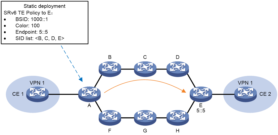
As shown in Figure 3, users can manually configure the SRv6 TE Policy on source node A. When deploying the SRv6 TE Policy, users need to specify its Color properties, Endpoint address, BSID, candidate path, and SID list.
Figure 3 Static Deployment of SRv6 TE Policy Schematic Diagram
Create SRv6 TE Policy automatically using ODN
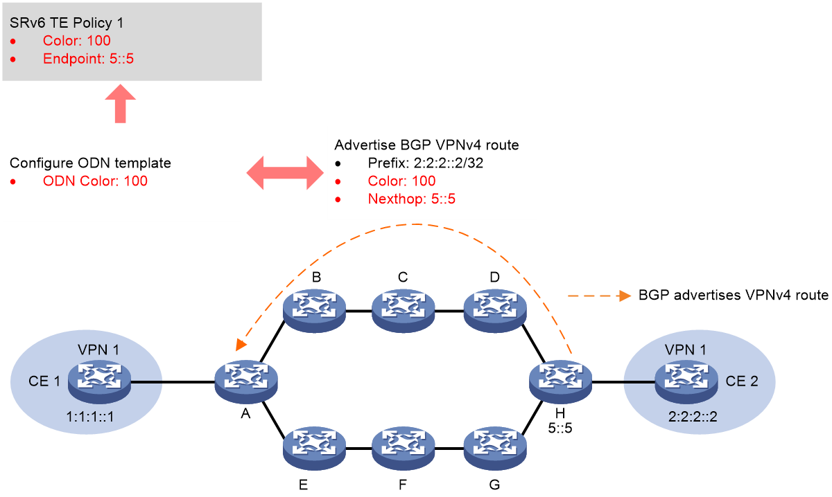
As shown in Figure 4, after creating an ODN template at node A, if the device receives a BGP route carrying the Color extended community attribute that matches the Color value of the ODN template, the next-hop address of this BGP route is used as the destination node address for the SRv6 TE Policy, and the Color value of the ODN template is used as the Color property for the SRv6 TE Policy. An SRv6 TE Policy is then automatically created.
When creating a SRv6 TE Policy based on the ODN template, you can use the IPv6 address Prefix list to filter BGP routes. BGP routes filtered through the IPv6 address Prefix list can trigger the creation of the SRv6 TE Policy, while BGP routes rejected by the IPv6 address Prefix list cannot trigger the establishment of the SRv6 TE Policy.
The SRv6 TE Policy will automatically apply for a BSID within the specified Locator section. After ODN automatically creates an SRv6 TE Policy, it will generate two candidate paths.
· The candidate path with a preference of 200 requires dynamic calculation of its SID list through affinity properties or Flex-Algo algorithm.
· The candidate path with a preference of 100 requires the SID list to be calculated by PCE. For a detailed introduction to PCE calculations, please refer to "Path establishment through PCE calculation Seg".
You can manually create a candidate path under the SRv6 TE Policy that is automatically created by the ODN function.
Figure 4 Create SRv6 TE Policy automatically using ODN
Controller issues an SRv6 TE policy
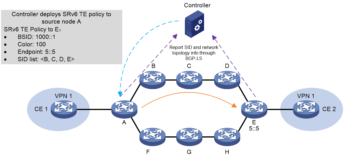
As shown in Figure 5, the process of the controller issuing SRv6 TE Policy is as follows:
1. The controller collects network topology and SID information (Info) through BGP-LS.
2. A BGP session for the BGP IPv6 SR Policy address family is established between the controller and the source node.
3. After calculating the SRv6 TE Policy's candidate paths, the controller uses the BGP session to send the Color properties, Endpoint address, BSID, candidate paths, and SID list of the SRv6 TE Policy to the source node. The source node device then generates the SRv6 TE Policy.
Figure 5 Schematic Diagram of SRv6 TE Policy Issued by Controller
To support SRv6 TE Policy, MP-BGP has defined a new subaddress family - the BGP SRv6 TE Policy address family, and has added SRv6 TE Policy network layer reachability information (NLRI), also known as SRv6 TE Policy route or BGP SRv6 TE Policy route. The SRv6 TE Policy route includes relevant configurations of the SRv6 TE Policy, such as BSID, Color, Endpoint, candidate path privilege level, SID list, and the weight of the SID list.
After establishing a BGP SRv6 TE Policy peer between devices, the device can pass the locally configured SRv6 TE Policy to the other end through the SRv6 TE Policy route. The peer device generates the corresponding SRv6 TE Policy based on the received SRv6 TE Policy route.
|
|
NOTE: For detailed information about BGP IPv6 SR Policy's NLRI, please refer to "SRv6 TE Policy." |
Learn SRv6 TE Policy via PCEP protocol
PCEP, defined by IETF and based on TCP protocol, sets forth a group of messages and objects that manage PCEP sessions, and transmitting requests and paths for multi-domain traffic engineering. PCEP interactions include path state reports being sent to Path Computation Element (PCE) by Path Computation Client (PCC). Likewise, PCE updates the path to PCC. In a scenario where controllers centrally calculate routes, PCEP typically acts as the communication protocol between controller and forwarder, in conjunction with the controller's routing function, to optimize global path. For a detailed explanation of PCE, please refer to the section "MPLS TE" in the "MPLS Configuration Guide".
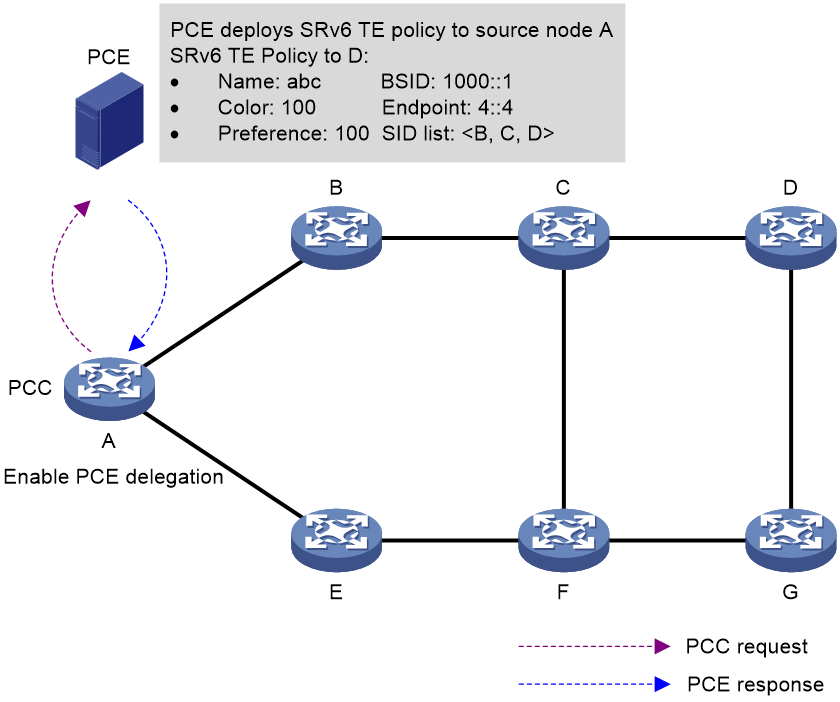
As shown in Figure 6, in the SRv6 TE Policy network, the SRv6 source node can generate SRv6 TE Policy through PCE hosting. Acting as PCC, the SRv6 source node delegates its path calculations to the controller (PCE), which then calculates candidate paths, establishes a SID list and generates the complete SRv6 TE Policy. The controller (PCE) sends the name, Color properties, Endpoint address, BSID, candidate paths, and the complete SID list of the generated SRv6 TE Policy to the SRv6 source node through the PCEP protocol.
Figure 6 Learn SRv6 TE Policy schematic through PECP protocol
Creating a segment list
The SID list, a key component of SRv6 TE Policy, represents the forwarding path. It supports two methods: manual creation and dynamic calculation.
Create the segment list manually
Create a list of SIDs manually using the command line, and specify the nodes that the message needs to pass through in the SID list.
Establish a segment list using a dynamically computed path
The SRv6 TE Policy manually created and the SRv6 TE Policy automatically generated by the ODN function both support establishing the SID list based on dynamically calculated paths at the source node of the SRv6 TE Policy.
The TE Policy supports dynamically calculating the path using the following method:
· Dynamically calculate the path based on affinity properties.
· Calculate the path dynamically according to the Flex-Algo algorithm.
· Use PCE to dynamically calculate the path.
Establish a segment List by dynamically calculating the path based on affinity properties
The process of SRv6 TE Policy dynamically calculating paths according to affinity properties is as follows:
1. The affinity properties rule determines which links can be used by the SRv6 TE Policy.
The affinity property rule associates the specified affinity property bit by referencing the name of the affinity property. This allows the SRv6 TE Policy to select a link that has the specified affinity property bit based on the affinity property rule.
¡ Link Properties: A 32-bit binary number, each bit represents an attribute with an attribute value of either 0 or 1.
¡ Affinity property bit: The value ranges from 0 to 31. When the affinity property bit is set to N, it indicates a comparison with the N+1 bit of the link properties from right to left. Only when the N+1 bit of the link properties is 1, does the link possess this affinity property.
For example, the affinity property name is blue, with a corresponding affinity property bit of 1; the affinity property name is red, with a corresponding affinity property bit of 5. Under different affinity property rules, the method to select links is as follows:
¡ The affinity properties rule is 'include-any', which means that the SRv6 TE Policy can only use the link when the link has any one of the specific affinity properties in this rule. 'include-any {bule, red}' means that if the second bit (corresponding to the blue affinity property bit) or the sixth bit (corresponding to the red affinity property bit) in the 32-bit link properties of the link is 1, then the link is available.
¡ The affinity property rule is set to 'include-all,' which means the SRv6 TE Policy can only use the link if it contains all the affinity properties within this rule. 'Include-all {bule, red}' denotes that the link is available if both the second bit (the affinity property bit corresponding to blue) and the sixth bit (the affinity property bit corresponding to red) in the 32-bit link properties are '1'.
¡ When the affinity property rule is set to 'exclude-any', it means that if a link has any of the affinity properties specified in the rule, the SRv6 TE Policy cannot use that link. 'Exclude-any {blue, red}' indicates that if the second bit in the 32-bit link properties (corresponding to the blue affinity property bit) OR the sixth bit (corresponding to the red affinity property bit) is 1, then the link is unavailable.
2. Calculate the path based on the metric type.
The types of metrics supported and the calculation methods by the SRv6 TE Policy are as follows:
¡ Select the link with the least hop count as the metric.
¡ Select the link with the lowest IGP (Interior Gateway Protocol) overhead value, using the IGP link overhead as the metric.
¡ Select the link with the lowest average interface delay, using the average interface delay as the metric.
¡ Select the link with the lowest TE metric as the measurement value, based on MPLS TE metric.
After the path calculation is complete, the device arranges all the SID corresponding to links or nodes on the path in an order from near to far, forming the SID list of the SRv6 TE Policy. When selecting a SID, the End SID is the preferred choice. If there is no End SID on the device, the End.X SID is selected.
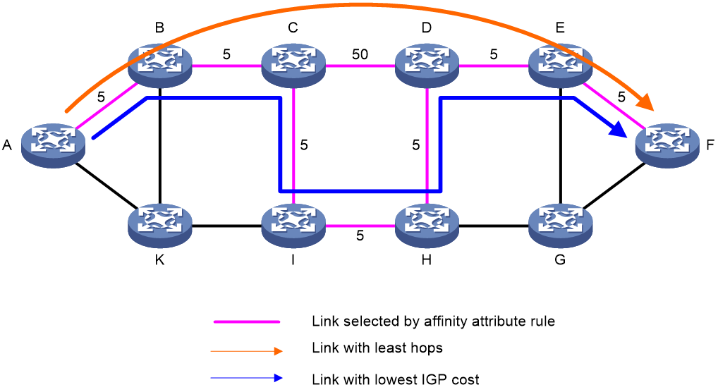
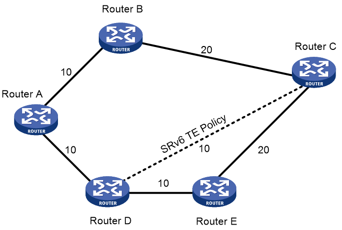
As shown in Figure 7, the digit in the middle of the link represents the cost value. The affinity property rule of SRv6 TE Policy is 'include-any'. The process of SRv6 TE Policy dynamically calculating path based on affinity properties is as follows:
1. Select the link with the affinity property of "red" according to the affinity property rule.
2. Select different links based on different metric types.
¡ When using 'hop count' as the 'metric', select the 'link' with the least 'hop count'. Use A-B-C-D-E-F as the forwarding 'path'.
¡ When using the IGP link overhead value as a metric, select the link with the smallest IGP overhead, using A-B-C-I-H-D-E-F as the forwarding path.
Figure 7 The SRv6 TE Policy dynamically calculates the path diagram based on affinity properties
Create a segment List based on the path dynamically calculated by the Flex-Algo algorithm
The SRv6 TE Policy uses a specified Flex-Algo algorithm to calculate the forwarding path. Once the forwarding path is obtained via the Flex-Algo algorithm, the device arranges all SIDs corresponding to the links or nodes on this path, from near to far, forming a SID list for the SRv6 TE Policy. When selecting SIDs, the priority is to select the End SID. If there's no End SID on the device, then the End.X SID is selected. For a detailed explanation of the Flex-Algo algorithm, please refer to the "Flex-Algo Technology White Paper".
The segment List is established through the path calculated by PCE
In the SRv6 TE Policy network, the SRv6 node can act as a PCC (Path Computation Client), establishing a SID list based on the path calculated by the PCE (Path Computation Element).
· nPCE: An entity in the network that provides path calculation services for devices on the network. It can perform path calculations within a zone, and also calculate the complete SID list in complex network environments. PCE is divided into the following two types:
¡ A Stateless PCE (Path Computation Element) is a type of PCE that only provides path computation services.
¡ Stateful Path Computation Element (Stateful PCE) is a type of PCE that holds all path information maintained by PCCs within the network. It can recalculate and optimize forwarding paths within a domain to maximize resource allocation and network resource usage. Stateful PCE includes two types: Active-Stateful Path Computation Element (Active-Stateful PCE) and Passive-Stateful Path Computation Element (Passive-Stateful PCE). Passive-Stateful PCE only maintains PCC's SID list information and cannot optimize paths in real-time based on network status and notify PCC to update paths. In contrast, Active-Stateful PCE can optimize paths in real-time based on network status and notify PCC to update paths.
· nPCC: Request PCE to execute path calculation and establish a forwarding path based on the returned path information from PCE. The PCC must be consistent with the PCE type. Therefore, there are two types of PCC:
¡ The Stateless PCC (Stateless Path Computation Client) is a type of PCC that only transmits path computation requests to the PCE.
¡ Stateful PCC (Stateful Path Computation Client) is a type of PCC which entrusts its SID list information to PCE, and the path information of the PCC is maintained by the Stateful PCE. Stateful PCC includes two types: Active-Stateful PCC and Passive-Stateful PCC. The SID list information of the Passive-Stateful PCC is only reported to the PCE and not computed by it, so it cannot update the path in real-time. The SID list information of the Active-Stateful PCC is reported to the PCE and computed by it, enabling real-time path updates.
· PCEP (Path Computation Element Protocol) is a communications protocol that runs between PCC and PCE. It is used to establish PCEP sessions and exchange PCEP messages. This protocol is based on TCP.
Figure 8 Schematic Diagram of the Path Calculation Process
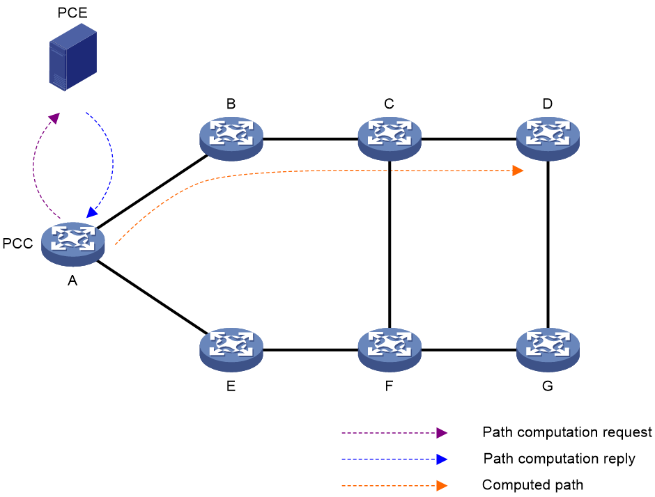
As shown in Figure 8, the PCE path calculation process is as follows:
1. The nPCC initiates a path calculation request to the PCE.
2. Upon receiving the request, the PCE calculates the path for the PCC.
3. After PCE completes the path calculation, it responds to the PCC's path request, asking PCC to create path information.
4. The SID list information is created under the candidate path of the SRv6 TE Policy, based on the path information calculated by the nPCC according to the PCE.
SRv6 TE Policy diverts traffic
Traffic can be directed to SRv6 TE Policy forwarding in a variety of ways, including the 'package' method.
· Color-based traffic steering
· 802.1p-based traffic direction
· Based on service-class traffic diversion
· Diverging based on TE class ID
· Based on APN ID for traffic diversion
· Based on static route diversion
· Draining based on policy routing
BSID-based traffic steering
If a packet is received with a destination IPv6 address that matches the BSID of an SRv6 TE Policy, that packet is forwarded via the said SRv6 TE Policy. Traffic diversion based on BSID is usually used in SID stitching scenarios. By adding another SRv6 TE Policy's BSID to the SID list of an SRv6 TE Policy, the length of the packet's SRH header can be reduced during the traffic forwarding process, enabling the stitching between different SRv6 TE Policies.
Color-based traffic steering
Color Drainage Mechanism
Color-based diversion directly routes traffic into SRv6 TE Policy based on the extended community attribute 'Color' and the 'destination address'. If a device has an SRv6 TE Policy whose 'Color' and 'Endpoint' address completely match the Color extended community attribute and the 'next-hop address' of the BGP route, that BGP route will be iterated to the SRv6 TE Policy. When a device receives a message that matches the BGP route, it will forward the message via the SRv6 TE Policy.
Example of the working process of Color's stream diversion
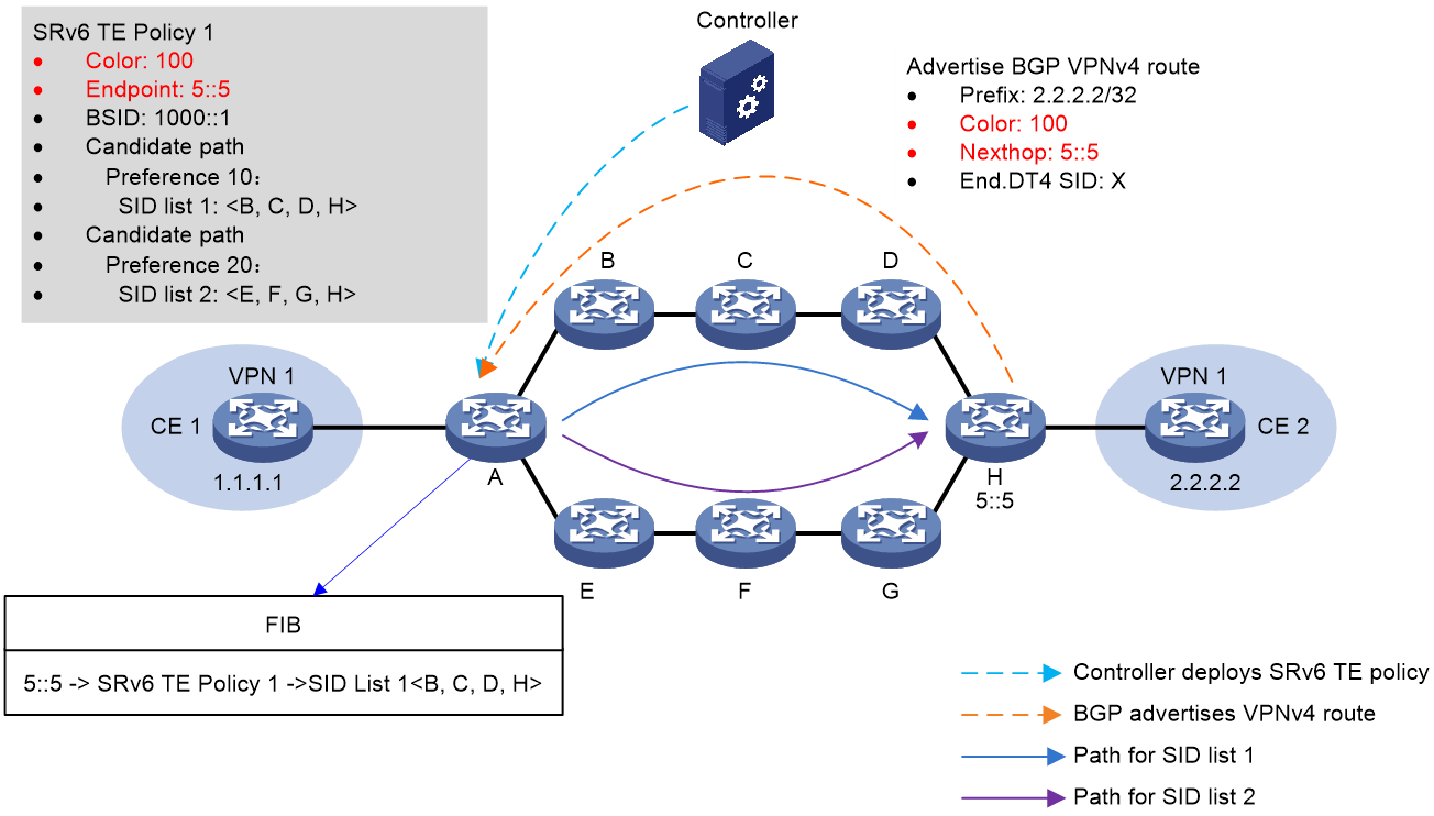
As shown in Figure 9, the process of color diversion is as follows:
1. The controller issues SRv6 TE Policy 1 to source node A, which has a Color of 100 and an EndPoint address of 5::5 on device H.
2. Device H transmits BGP VPNv4 route 2.2.2.2/32 to the source node device A. The route's Color extended community attribute value is 100, with the next hop being device H's address at 5::5.
3. When source node A receives the BGP VPNv4 route 2.2.2.2/32, it iterates this route to SRv6 TE Policy 1 based on the extended community attribute 100 ('Color') and the next-hop address 5::5. Packets matching this BGP route will be forwarded via SRv6 TE Policy 1.
Figure 9 Schematic Illustration of Color Stream Flow
DSCP-based traffic steering
DSCP Drainage Mechanism
When directing packets to the SRv6 TE Policy based on the DSCP values of the packets, it is necessary to deploy a group of SRv6 TE Policies. This group consists of several SRv6 TE Policies with different Color properties but the same Endpoint addresses.
The working mechanism based on DSCP diversion is:
1. Add multiple SRv6 TE Policies with different Color properties to a single SRv6 TE Policy group, and specify the mappings between the DSCP values and the Color properties.
2. Draining to the SRv6 TE Policy group can be achieved by any of the following methods:
¡ Configure the tunneling policy and bind the specific destination address with the SRv6 TE Policy group in the tunneling policy. This will direct the traffic towards the specific destination address to be forwarded to the SRv6 TE Policy group.
¡ Set up the tunneling policy and configure the SRv6 TE Policy group as the priority tunnel in the policy. When the next-hop address of the route is the destination node address of the SRv6 TE Policy group, the traffic is preferentially directed and forwarded within the SRv6 TE Policy group.
¡ After finding the SRv6 TE Policy group that matches the Color and Endpoint address with the BGP route's Color extended community attribute and next-hop address, iterate the BGP route to the SRv6 TE Policy group.
3. The packet's DSCP value is used to find its associated Color properties. These properties are then matched with a specific SRv6 TE Policy in the SRv6 TE Policy group. This creates a mapping from DSCP to Color to SRv6 TE Policy, enabling the forwarding of packets with specified DSCP through a specific SRv6 TE Policy.
Example of DSCP Stream Diversion Working Process
As shown in Figure 10, the process of DSCP diversion is as follows:
1. The controller sends SRv6 TE Policy to the source node A. The color of SRv6 TE Policy 1 is 100 and the EndPoint is the address 5::5 of the device H. The color of SRv6 TE Policy 2 is 200, and its EndPoint is also the address 5::5 of the device H.
2. Device H transmits the BGP VPNv4 route 2.2.2.2/32 to the source node, device A, with the next-hop address as 5::5.
3. Create a SRv6 TE Policy group 111 on source node device A with its EndPoint as the address 5::5 of device H. Within the SRv6 TE Policy group, create Color and DSCP mappings with Color 100 mapping to DSCP 10 and Color 200 mapping to DSCP 20. Afterwards, configure the tunneling policy on source node A to bind the SRv6 TE Policy group to the destination address 2.2.2.2.
4. The source node A locates the matching tunnel binding policy based on the packet's destination address, thus linking to the SRv6 TE Policy group. Subsequently, it uses the packet's DSCP value to find the corresponding Color, and then matches the specific SRv6 TE Policy inside the SRv6 TE Policy group based on the Color. The optimal candidate path is selected within this SRv6 TE Policy and the packet with a DSCP value of 10 is forwarded along the B -> C -> D -> H path in accordance with the SID List in the candidate path, thereby achieving DSCP diversion of the packet.
Figure 10 DSCP Drainage Schematic Diagram

802.1p-based traffic direction
Mechanism
When directing traffic based on the 802.1p value of packets to the SRv6 TE Policy, it is necessary to deploy a group of SRv6 TE Policies. This group is made up of SRv6 TE Policies with different color properties, but with the same Endpoint address.
The working mechanism based on 802.1p diversion is as follows:
1. Add multiple SRv6 TE Policies with different Color properties to a single SRv6 TE Policy group, and specify the mappings between the 802.1p values and the Color properties.
2. You can divert traffic to the SRv6 TE Policy group using any of the following methods.
¡ Configure the tunneling policy and bind the specified destination address with the SRv6 TE Policy group in the tunneling policy. This enables traffic heading to the destination address to be introduced and forwarded to the SRv6 TE Policy group.
¡ Configure the tunneling policy, setting the SRv6 TE Policy group as the priority tunnel in the tunneling policy. When the next-hop address of the route is the destination node address of the SRv6 TE Policy group, the traffic is preferentially introduced and forwarded within the SRv6 TE Policy group.
¡ After finding the SRv6 TE Policy group that matches the Color and Endpoint address with the Color extended community attribute and next-hop address of the BGP route, iterate this BGP route to the SRv6 TE Policy group.
3. The packet's Color property is found based on its 802.1p value, which then matches a specific SRv6 TE Policy in the SRv6 TE Policy group. This creates a mapping relationship of 802.1p->Color->SRv6 TE Policy, enabling the forwarding of packets carrying a specified 802.1p value through a specified SRv6 TE Policy.
802.1p-based traffic direction process
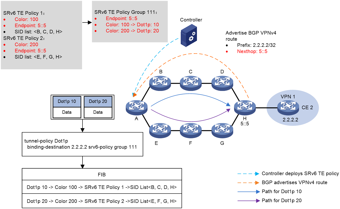
As shown in Figure 11, the process of the 802.1p stream diversion is as follows:
1. The controller issues SRv6 TE Policy to the source node A, where SRv6 TE Policy 1 has a Color of 100 and the EndPoint is the address 5::5 of the device H; SRv6 TE Policy 2 has a Color of 200 with the same EndPoint as the address 5::5 of device H.
2. The device H transmits the BGP VPNv4 route 2.2.2.2/32 to the source node device A, with the next-hop address being 5::5.
3. Create an SRv6 TE Policy group 111 on the source node device A, with the EndPoint being the address 5::5 of device H. Within the SRv6 TE Policy group, create the mappings of Color and Dot1p, where Color 100 maps to Dot1p 10, and Color 200 maps to Dot1p 20. Subsequently, configure the tunneling policy on the source node A, associating the SRv6 TE Policy group with the destination address 2.2.2.2.
4. Source node A locates the matching tunnel binding policy based on the destination address of the packet, thereby associating with SRv6 TE Policy group. It then looks up the mapped Color according to the Dot1p value of the packet. Based on Color, it matches to a specific SRv6 TE Policy within the SRv6 TE Policy group, selects the optimal candidate path in the SRv6 TE Policy, and forwards the packet with Dot1p value of 10 according to the SID List in the candidate path via B -> C -> D -> H. Thus, it achieves the Dot1p diversion of the packet.
Figure 11 Network diagram
Based on service-class traffic diversion
The load balancing mechanism of service-class
A service-class is a local identification mark for devices, which can identify service-class of traffic by QoS policy. When directing traffic based on the service-class identification to SRv6 TE Policy, it is necessary to deploy a group of SRv6 TE Policies. The SRv6 TE Policy group is composed of multiple SRv6 TE Policies with different Color properties, but same Endpoint addresses.
The working mechanism based on service-class diversion is:
1. Add multiple SRv6 TE Policies with different Color properties to a group of SRv6 TE Policies, and assign a mapping relationship between the service-class values and the Color properties.
2. You can divert traffic to the SRv6 TE Policy group using any of the following methods.
¡ Configure the tunneling policy, and bind the specified destination address to the SRv6 TE Policy group in the tunneling policy. This enables traffic heading to that destination address to be directed towards the SRv6 TE Policy group for forwarding.
¡ Configure the tunneling policy and set the SRv6 TE Policy group as the priority tunnel in the tunneling policy. When the next-hop address of the route is the destination node address of the SRv6 TE Policy group, traffic is preferably directed and forwarded within the SRv6 TE Policy group.
¡ After finding the SRv6 TE Policy group that matches the Color and Endpoint address with the BGP route's Color extended community attribute and next-hop address, iterate this BGP route to the SRv6 TE Policy group.
3. Based on the service-class identifier of the message, the associated Color property is identified, then the SRv6 TE Policy within the SRv6 TE Policy group is matched using the Color property. This forms a mapping relationship from service-class to Color to SRv6 TE Policy, enabling the forwarding of messages with specified service-class identifiers through a particular SRv6 TE Policy.
Example of the service-class stream diversion workflow
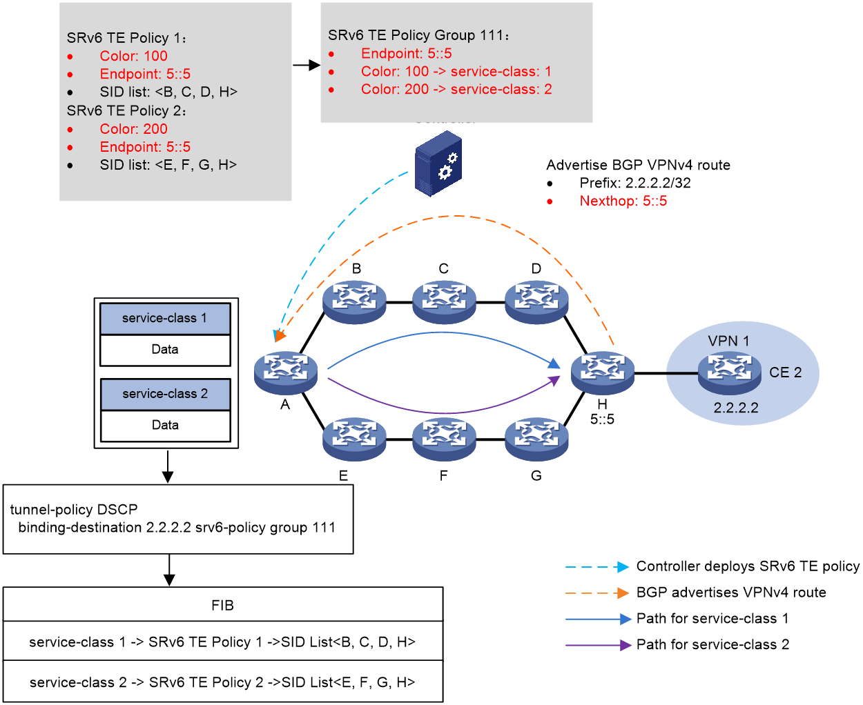
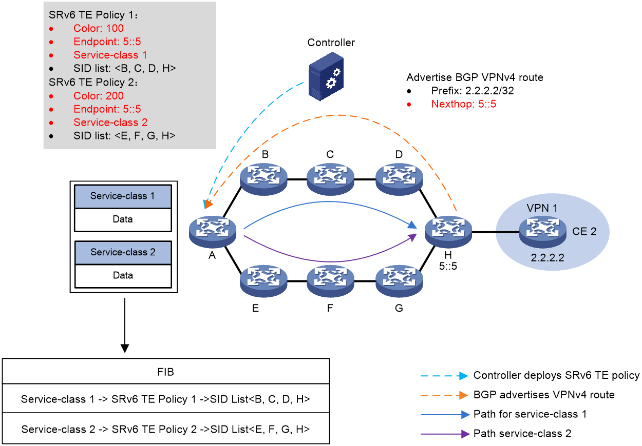
As shown in Figure 12, the process of diverting stream in service-class is as follows:
1. The controller sends SRv6 TE Policy to source node A. The Color of SRv6 TE Policy 1 is 100, and the EndPoint is the address 5::5 of device H; The Color of SRv6 TE Policy 2 is 200, and the EndPoint is also the address 5::5 of device H.
2. Device H transmits the BGP VPNv4 route 2.2.2.2/32 to the source node device A, with the next-hop address being 5::5.
3. Create an SRv6 TE Policy group 111 on the source node device A with its EndPoint being the address 5::5 of device H. Inside the SRv6 TE Policy group, establish mappings between Color and service-class, where Color 100 maps to service-class 1 and Color 200 maps to service-class 2. Then, configure the tunneling policy on the source node A, binding the SRv6 TE Policy group with the destination address 2.2.2.2.
4. Source node A, using the destination address of the packet, identifies the matching tunnel binding policy. This associates it with the SRv6 TE Policy group. From here, it uses the service-class identifier of the packet to find the corresponding Color. This Color then matches a specific SRv6 TE Policy within the SRv6 TE Policy group. The optimal candidate path is then selected within this SRv6 TE Policy, and the packet, with a service-class value of 1, is forwarded along the B -> C -> D -> H path according to the SID List in the candidate path. This effectively implements service-class flow diversion for the packet.
Figure 12 Schematic Diagram of service-class Stream Diversion
CBTS-based traffic steering
Based on the drainage mechanism of CBTS
SRv6 TE Policy CBTS (Class-based Tunnel Selection), a selection method for SRv6 TE Policy tunnels, differs from traditional tunnel selection methods. CBTS can select the corresponding SRv6 TE Policy tunnel based on the forwarding class (FC) of traffic, thereby providing different forwarding services for different operations.
CBTS for SRv6 TE policies operates as follows:
· Specify the forwarding class (FC) of the SRv6 TE Policy (Service-class properties).
· Through traffic classification, match the traffic that needs to be forwarded by the SRv6 TE Policy, and map the traffic of different services into different forwarding classes (FC). The business traffic mapped to the specified forwarding class can be forwarded through the SRv6 TE Policy tunnel with the corresponding forwarding class.
When the traffic matches multiple SRv6 TE Policy tunnels, the SRv6 TE Policy CBTS prefers to forward the traffic according to the following rules of the SRv6 TE Policy tunnel.
1. The device will prioritize selecting the SRv6 TE Policy with the same forwarding class (FC) value as the traffic to forward this traffic.
2. When multiple SRv6 TE Policies have the same forwarding class (FC) value as the traffic, if there is only one stream and it's for per-flow load sharing, a random SRv6 TE Policy is selected to forward the traffic. If there's only one stream but it's for per-package load sharing OR multiple streams exist, then the traffic load shares among the SRv6 TE Policies with the same FC.
3. If there is no SRv6 TE Policy with a forwarding class (FC) value matching the traffic, select the SRv6 TE Policy with the lowest tunnel forwarding privilege level to forward the traffic. The smaller the FC value of the SRv6 TE Policy, the lower the priority of tunnel forwarding. Tunnels without a configured FC have the lowest priority.
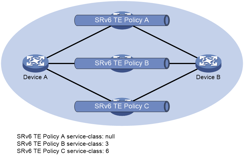
As shown in Figure 13, the principle for selecting a tunnel is as follows:
· The traffic with a forwarding class (FC) value of 3 from Device A to Device B is forwarded through SRv6 TE Policy B.
· The traffic with a forwarding class (FC) value of 6 is passed from Device A to Device B through SRv6 TE Policy C.
· The traffic with a forwarding class (FC) value of 4 is passed from Device A to Device B through SRv6 TE Policy A.
· Uses SRv6 TE policy A to forward flows that do not have a service class value.
Figure 13 Diagram of SRv6 TE Policy CBTS
Example of CBTS Stream Diversion Working Process
As shown in Figure 14, the work process based on CBTS drainage is as follows:
1. The controller issues SRv6 TE Policy to source node A. SRv6 TE Policy 1 has a Color of 100, Service-class of 1, and its EndPoint is the address 5::5 of device H. SRv6 TE Policy 2 also has an EndPoint at the address 5::5 of device H, but with a Color of 200 and a Service-class of 2.
2. Device H transmits BGP VPNv4 route 2.2.2.2/32 to the source node device A, with the next-hop address being 5::5.
3. At the source node A, the Service-class value of messages is marked using QoS policy, based on features like 5-tuple.
4. When the source node A receives a packet with a Service-class of 1, it passes it forward using SRv6 TE Policy 1. Similarly, when source node A receives a packet with a Service-class of 2, it transfers it using SRv6 TE Policy 2.
Figure 14 Schematic Diagram of CBTS Stream Diversion
Diverging based on TE class ID
The TE class ID diversion mechanism
The TE class ID is a local identification for a device, which can identify traffic based on QoS policy. Compared to service-class, there are more TE class IDs and intelligent policy routing functions of SRv6 TE Policy can be achieved based on TE class ID. When routing packets to SRv6 TE Policy based on TE class ID, an SRv6 TE Policy group needs to be deployed. The SRv6 TE Policy group consists of multiple SRv6 TE Policies with different Color properties but the same Endpoint address.
The working mechanism based on TE class ID diversion is as follows:
1. Add multiple SRv6 TE Policies with different Color properties to a single SRv6 TE Policy group, and specify the mappings between the TE class ID value and the Color property.
2. You can implement traffic diversion to the SRv6 TE Policy Group using any of the following methods:
¡ Configure the tunneling policy and bind the specified destination address with the SRv6 TE Policy group in the policy. This allows traffic going to that destination address to be directed and forwarded to the SRv6 TE Policy group.
¡ Configure the tunneling policy and set the SRv6 TE Policy group as the prioritized tunnel in the tunneling policy. When the next-hop address of the route is the destination node address of the SRv6 TE Policy group, traffic is preferentially introduced and forwarded within the SRv6 TE Policy group.
¡ After finding the SRv6 TE Policy group that matches the Color and Endpoint address with the BGP route's extended community attribute and next-hop address, iterate the BGP route to the SRv6 TE Policy group.
3. Based on the TE class ID identify in the message, find the associated Color properties, and then match it to a specific SRv6 TE Policy in the SRv6 TE Policy group. This forms the mappings of TE class ID->Color->SRv6 TE Policy, enabling messages with the specified TE class ID to pass through the designated SRv6 TE Policy for forwarding.
Example of the Drainage Work Process for TE Class ID
As shown in Figure 15, the process of stream diversion for the TE class ID is as follows:
1. The controller issues SRv6 TE Policy to source node A. The color of SRv6 TE Policy 1 is 100 and the EndPoint is the address 5::5 of device H. The color of SRv6 TE Policy 2 is 200 and the EndPoint is also the address 5::5 of device H.
2. The device H transmits the BGP VPNv4 route 2.2.2.2/32 to the source node device A, with the next-hop address being 5::5.
3. Create SRv6 TE Policy group 111 on source node device A, with its EndPoint being the address 5::5 of device H. Within the SRv6 TE Policy group, create mappings between Color and TE class ID, where Color 100 maps to TE class ID 1, and Color 200 maps to TE class ID 2. Afterwards, configure the tunneling policy on source node A, binding the SRv6 TE Policy group to the destination address 2.2.2.2.
4. Source node A locates the matching tunnel binding policy based on the destination address of the packet, which then associates with the SRv6 TE Policy group. Following this, it identifies the mapped Color from the packet's TE class ID. With this Color, it finds a specific SRv6 TE Policy within the SRv6 TE Policy group. In this SRv6 TE Policy, it selects the optimal candidate path and forwards the packet with a TE class ID value of 1 through the B -> C -> D -> H path based on the SID List in the candidate path, hence implementing the offload of the packet's TE class ID.
Figure 15 Schematic diagram of TE class ID diversion

Based on APN ID for traffic diversion
The APN ID is an identify (ID) information for an application defined in APN6 (Application-aware IPv6 Networking). Network devices use the APN ID to differentiate the business streams of different applications. For a detailed introduction based on APN ID diversion, please refer to the "APN6 Technology White Paper".
Based on static route diversion
After creating a static route that iterates to the SRv6 TE Policy on the device, traffic is redirected to the SRv6 TE Policy via the static route. If the device receives a packet matching the static route, the packet is forwarded through the specified SRv6 TE Policy.
Draining based on policy routing
Create a policy routing on the device, specifying the SRv6 TE Policy through the apply clause in the policy route, diverting traffic to the SRv6 TE Policy through policy routing. If the device receives a packet matching the rules defined by the policy route, forward the packet via the specified SRv6 TE Policy.
Drain based on QoS policy
Create a QoS policy on the device, which binds the redirect SRv6 TE Policy traffic behavior. Then apply the QoS policy to the interface or globally. The device will redirect the packet traffic, meeting the matching condition in the QoS policy, to the SRv6 TE Policy.
Based on FlowSpec Diversion
A Flowspec route is created on the Flowspec controller, which defines the packet match rule and the traffic forwarding action redirecting to the SRv6 TE Policy. The Flowspec controller releases the Flowspec route to the Flowspec forwarder, i.e. the SRv6 TE Policy source node, via an expanded BGP protocol. The SRv6 TE Policy source node forwards traffic that matches the packet rule to a specified SRv6 TE Policy based on the traffic forwarding action defined in the Flowspec route.
Self-drainage function
Self-draining refers to the release of SRv6 TE Policy tunnels OR SRv6 TE Policy groups into IGP (OSPFv3 or IS-IS) routing, allowing SRv6 TE Policy tunnels OR SRv6 TE Policy groups to participate in the computation of IGP routing. This allows traffic to pass through SRv6 TE Policy tunnels OR SRv6 TE Policy groups for forwarding.
The current automatic diversion only supports the IGP Shortcut method, also known as autoroute announce (AutoRoute Announce). This function treats the SRv6 TE Policy or SRv6 TE Policy group as a direct link connecting the tunnel Ingress node (head node) and the Egress node (tail node). The SRv6 TE Policy or SRv6 TE Policy group is considered when calculating the IGP route on the tunnel's Ingress node.
The IGP Shortcut function does not release the SRv6 TE Policy tunnel or SRv6 TE Policy group as a link to its neighbors through the IGP routing protocol. Therefore, other devices do not consider the SRv6 TE Policy tunnel or SRv6 TE Policy group when performing route calculations.
|
|
NOTE: After directing traffic into the SRv6 TE Policy group through self-flow introduction, the traffic will search for the matching SRv6 TE Policy within the group using DSCP or Dot1p diversion methods, and the traffic will be forwarded through this SRv6 TE Policy. |
For instance, in Figure 16, there is an SRv6 TE Policy tunnel between Device D and Device C. IGP Shortcut enables the source node, Device D, to utilize this tunnel while computing the IGP route. Consequently, it directs the messages entering Device D to the SRv6 TE Policy tunnel between Device D and Device C.
Figure 16 Schematic Diagram of IGP Shortcut and Forwarding Adjacency
SRv6 TE Policy Routing
Choose SRv6 Traffic Engineering Policy Routing
The process in the SRv6 TE Policy where datagrams are directed and paths are selected is as follows:
1. Select the valid candidate path with the highest privilege level in the SRv6 TE Policy to forward traffic.
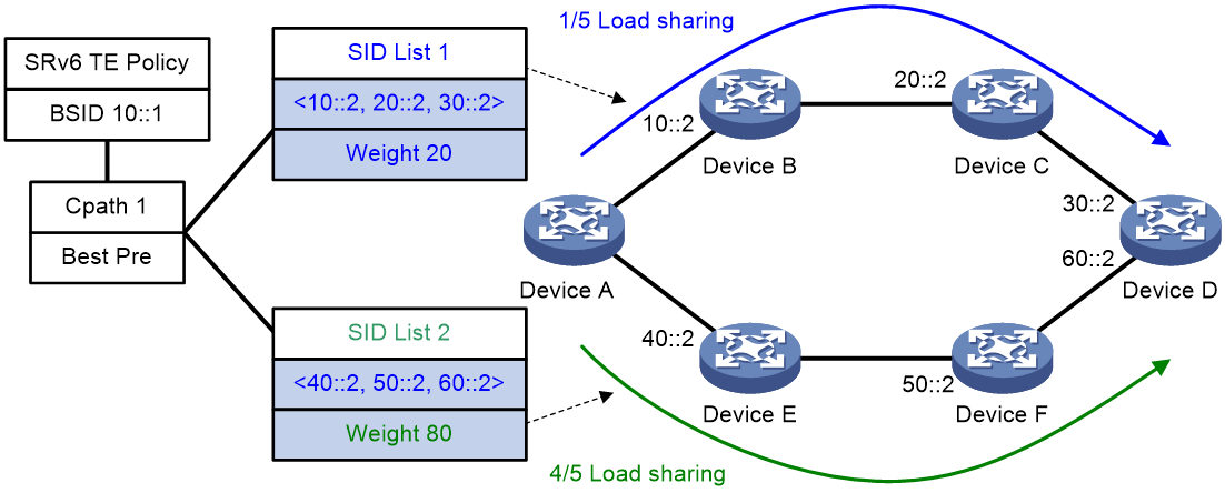
2. Perform Weighted Equal Cost Multi-Path (WECMP), which is load sharing based on weight, among the SID lists of the valid candidate paths with the highest privilege level. This is specifically for the traffic forwarded through SRv6 TE Policy. Let's assume that the candidate paths include n valid SID lists, if the weight of the xth SID list is Weight x, then the proportion of traffic forwarded by the xth SID list is Weight x/(Weight 1+Weight 2+...+Weight n).
As illustrated in Figure 17, the traffic is forwarded based on the effective SRv6 TE Policy selected by BSID, and then the path with the highest priority level is chosen to forward the traffic. This candidate path contains two valid SID lists: SID List 1 and SID List 2, with weights of 20 and 80, respectively. When traffic is routed through this SRv6 TE Policy, the proportion of traffic forwarded by SID List 1 and SID List 2 is 1/5 and 4/5, respectively.
Figure 17 Schematic Diagram of the Routing Process When SRv6 TE Policy Transfers Traffic
SRv6 TE Policy Data encapsulation and forwarding
In the SRv6 TE Policy, the message supports both Encapsulation and Intrusion methods. Encapsulation method involves adding a new IPv6 header and SRH extension header outside the original message, while Intrusion method inserts the SRH extension header after the original IPv6 header.
Based on the differences in encapsulation methods, the process of forwarding packets varies slightly.
Packet forwarding of SRv6 TE Policy with the encapsulation method
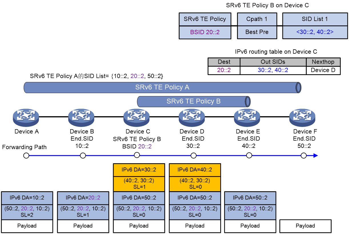
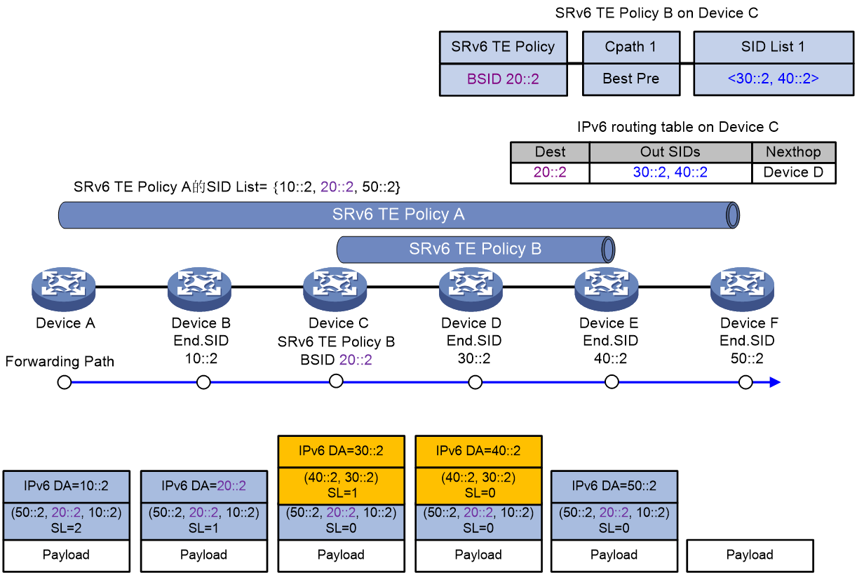
As shown in Figure 18, taking the example of BSID-based diversion in the SID stitching scenario, the message forwarding process of the SRv6 TE Policy is as follows:
1. Device A directs traffic to SRv6 TE Policy A for forwarding. SRv6 TE Policy A's SID incorporates the BSID 20::2 of SRv6 TE Policy B. According to SRv6 TE Policy A, the packet is encapsulated with the SRH header, and the SRH header carries the SID list {10::2, 20::2, 50::2}. Among them, 10::2 represents the End SID of Device B, and 50::2 represents the End SID of Device F.
2. Device A transmits the encapsulated message to the next hop, Device B.
3. After receiving the message, Device B obtains the next hop as Device C from the SRH, and transmits the message to Device C.
4. Upon receiving the packet, Device C identifies the destination address as 20::2, which is the BSID for local SRv6 TE Policy B. This policy's encapsulation method is the Encaps mode. Therefore, Device C encapsulates the packet with an outer IPv6 header and SRH according to SRv6 TE Policy B. The SRH header carries a SID list of {30::2, 40::2}, where 30::2 is the End SID for Device D, and 40::2 is the End SID for Device E. The destination address of the outer IPv6 header is updated to 30::2, with the next hop set to Device D, and the packet is transmitted to Device D.
5. Upon receiving the packet, Device D identifies Device E as the next hop based on the outer SRH and transmits the packet to it.
6. After Device E receives the message, it checks the SL value in the outer SRH header and finds that SL=0. Device E then performs decapsulation of the outer IPv6 header and SRH header, deletes the encapsulated header, and transmits the message to Device F based on the destination address of the inner message.
7. Upon receiving the message, Device F checks the SL value in the outer SRH header and finds that SL=0. Being the tail node of SRv6 TE Policy A, Device F performs decapsulation on the outer IPv6 header and SRH header of the message, deleting the encapsulated message header.
Forward the SRv6 TE Policy messages using the 'encapsulation' method of Insert
As shown in Figure 19, using the scenario of SID Splicing based on BSID diversion as an example, the packet forwarding process of SRv6 TE Policy is:
1. Device A directs traffic to SRv6 TE Policy A for forwarding. To reduce the length of the SRH encapsulation, BSID 20::2 from SRv6 TE Policy B is introduced into the SID of SRv6 TE Policy A. According to SRv6 TE Policy A, an SRH header is encapsulated for the packets, carrying a SID list of {10::2, 20::2, 50::2}. Herein, 10::2 is the End SID for Device B, and 50::2 is the End SID for Device F.
2. Device A transmits the encapsulated message to the next hop, Device B.
3. Upon receiving the message, Device B extracts the 'next hop' as Device C from the SRH, and transmits the message to Device C.
4. Upon receiving the message, Device C discovers that the destination address of the message is 20::2, which belongs to local SRv6 TE Policy B's BSID. SRv6 TE Policy B uses the 'Insert' mode for encapsulation. As a result, Device C inserts SRH after the original IPv6 message header based on SRv6 TE Policy B. The SID list carried by the SRH header includes {30::2, 40::2}. Here, 30::2 is Device D's End SID, and 40::2 is Device E's End SID. The destination address for the outer IPv6 header is updated to 30::2, with the next hop being Device D. The message is then transmitted to Device D.
5. After Device D receives the packet, it obtains the next hop, Device E, according to the outer stratum SRH, and then transmits the packet to Device E.
6. After receiving the packet, Device E checks the SL value in the outer SRH header and finds that SL=0. Device E then performs decapsulation on the outer SRH header and updates the destination address based on the inner SRH before transmitting the packet to Device F.
7. Upon receiving the packet, Device F checks the outer SRH header and finds that SL=0. As the tail node of SRv6 TE Policy A, Device F performs decapsulation of the outer IPv6 header and SRH header, deleting the encapsulated packet header.
Figure 19 Forward the SRv6 TE Policy message in the encapsulation mode of Insert.
Expanded working principle of SRv6 TE Policy
Determine the validity of the SRv6 TE Policy
Traffic forwarding through an invalid SRv6 TE Policy will cause traffic forwarding to fail. Therefore, only when the SRv6 TE Policy is valid, can traffic be forwarded through this SRv6 TE Policy.
The validity rule for SRv6 TE Policy is as follows: If there is at least one valid SID list in the SRv6 TE Policy, then the SRv6 TE Policy is valid; otherwise, the SRv6 TE Policy is invalid.
The SID list is invalid when any of the following situations occur:
· The SID list is empty.
· The weight of the SID list is 0.
· The SR node cannot communicate with the first-hop IPv6 address in the SID list.
· Detect if the BFD or SBFD session in the SID list is down.
High availability (HA) of SRv6 TE Policy
SRv6 TE Policy is linked with echo BFD
When checking the SRv6 TE Policy using the echo BFD method, it's not necessary to configure the same identifier (ID) on both the local and the Reflector ends. Compared to the SBFD method of checking SRv6 TE Policy, the echo BFD method's configuration is simpler, eliminating the need to plan identifiers (ID) on both local and remote ends.
The process of echo BFD detecting SRv6 TE Policy is as follows:
1. The head node transmits the BFD echo message, and the BFD echo message encapsulates the SID list in the SRv6 TE Policy.
2. Upon receiving the BFD echo message, the tail node forwards it back to the head node via the shortest path of the IPv6 route.
3. If the head node can receive the BFD echo packet forwarded back by the tail node before the detection time expires, it is considered that the SID list of the SRv6 TE Policy is normal. Otherwise, the head node considers the SID list to be faulty. If all the SID lists under the main path fail, the BFD triggers the switchover between the main and backup paths.
When using echo message mode to monitor SRv6 TE Policy, if multiple SID lists exist in the selected candidate path, the SRv6 TE Policy will set up several BFD sessions to individually monitor the forwarding path corresponding to each SID list.
When checking the SRv6 TE Policy using the BFD method, BFD messages support both Insert and encapsulation methods. By default, BFD messages use the Insert encapsulation method.
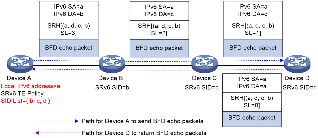
As shown in Figure 20 (Ref), Device A is configured with an SRv6 TE Policy which is verified through an echo message type BFD. When BFD message employs the default encapsulation method of "Insert", Device A will create a unique BFD message. This message's source address will be Device A's local IPv6 address a and the IPv6 address a will be inserted into the 'SID' list at the 'SL=0' position. Upon receiving the BFD message, Device D updates the destination address of the IPv6 header to a. Then, based on the IPv6 address a, it will look up the IPv6 routing table and loopback the message to Device A.
For BFD sessions using the echo message method, the source address of the echo message is determined according to the following precedence order.
1. The command bfd echo-source-ipv6 designates the source address of the packet.
2. The source address for the BFD session specified by the echo command.
3. The source address of the BFD session specified by the srv6-policy bfd echo command.
Figure 20 The BFD session detection via echo message method examines the SRv6 TE Policy (Insert encapsulation).
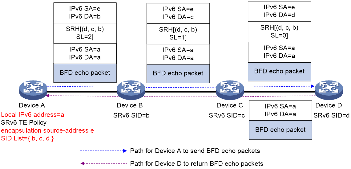
As shown in Figure 21, SRv6 TE Policy is configured on Device A and is monitored by echo message-based BFD. When BFD messages use an Encaps encapsulation technique, Device A first constructs a BFD message with both the source address and destination address set to Device A's local IPv6 address 'a'. Device A then encapsulates an additional IPv6 header and SRH header on top of the BFD message, with the source address of the outer Ipv6 header designated by the 'encapsulation source-address' command and the SRH header containing a list of SID for the SRv6 TE Policy. Upon receiving the BFD message, Device D decapsulates the outer Ipv6 and SRH headers, looks up the IPv6 routing table using address 'a', and loops back the message back to Device A.
The BFD session detection using echo message method encapsulates SRv6 TE Policy.
The SRv6 TE Policy is linked with SBFD
SRv6 TE Policy does not maintain its own state through messages transmitted between devices. It can use Seamless BFD (SBFD) to detect faults in the SRv6 TE Policy path. By utilizing SBFD to check the connectivity of SRv6 TE Policy, it can provide millisecond-level fault detection speed and achieve rapid fault switchover.
The process of SBFD detecting SRv6 TE Policy is as follows:
1. The head node, acting as the Initiator, transmits the SBFD message, which encapsulates the SID list in the SRv6 TE Policy.
2. Upon receiving the SBFD message as the tail node of the Reflector, it checks if the remote identifier (ID) carried in the message matches the locally configured identifier (ID). If they match, the Reflector will transmit (Tx) the SBFD response message to the Initiator via IPv6 route. If they don't match, the Reflector will discard the received SBFD message.
3. If the head node receives the SBFD response message before the detection time expires, it is considered that the SID list of the SRv6 TE Policy is normal. Otherwise, the head node assumes a fault in the SID list.
When detecting SRv6 TE Policy, if there are multiple SID lists in the selected candidate path, the SRv6 TE Policy will establish multiple SBFD sessions to separately detect the forwarding path corresponding to each SID list.
When inspecting the SRv6 TE Policy through the SBFD method, the SBFD messages support two types of encapsulation methods: Insert and Encaps. By default, the SBFD messages employ the Insert encapsulation method.
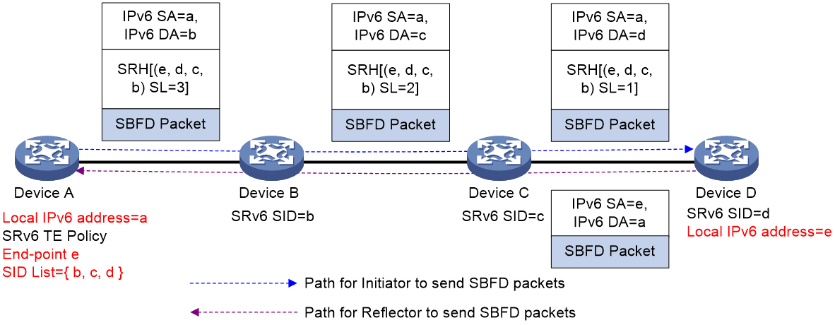
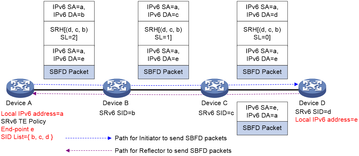
As shown in <field name="Ref" value="Figure 22"/>, an SRv6 TE Policy is set up on Device A and its status is monitored using SBFD. When the SBFD packets use the default 'Insert' encapsulation method, Device A will create SBFD packets. The source address of the SBFD packets is Device A's local IPv6 address 'a', and the End-point address 'e' of the SRv6 TE Policy is inserted into the SID list at position SL=0. When Device D receives the SBFD packets, it carries out decapsulation on the IPv6 and SRH headers. The source address 'a' in the SBFD packet is used to look up the IPv6 routing table, then a new SBFD packet is created and returned to Device A.
Figure 21 The detection process (encapsulation insertion) of SBFD for SRv6 TE Policy
As shown in Figure 22, SRv6 TE Policy is configured on Device A and is monitored using SBFD. When the Encaps encapsulation mode is used for SBFD messages, Device A constructs the SBFD message. The source address of the SBFD message is the local IPv6 address (a) of Device A, and the End-point address (e) of the SRv6 TE Policy is used as the destination address of the SBFD message. An additional IPv6 header and SRH header are encapsulated outside the SBFD message, with the source address of the IPv6 header being (a) again. When Device D receives the SBFD message, it decapsulates the outer IPv6 and SRH headers. Based on the source address (a) of the SBFD message, it searches the IPv6 routing table and re-constructs the SBFD message to return to Device A.
Figure 22 The detection process (encapsulation) of SBFD for SRv6 TE Policy
BFD detects the specified return path of the SRv6 TE Policy
If multiple SRv6 TE Policies exist between the head node and tail node of an SRv6 TE Policy, and these SRv6 TE Policies' connectivity is tested using SBFD or BFD echo method, by default, SBFD/BFD return packets are all forwarded via IP path. If an intermediate equipment experiences a fault, then the return packets could be discarded, leading to the SBFD/BFD session going down and mistakenly identifying all of the SRv6 TE Policies' SID list as having a fault.
To solve the above problem, SBFD/BFD return packets can be forwarded according to the specified SID list of the SRv6 TE Policy, ensuring connectivity.
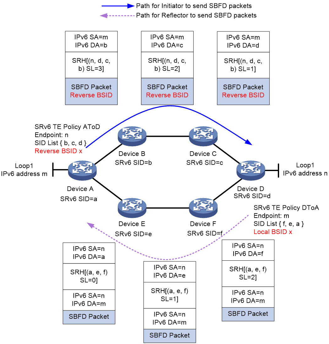
As shown in Figure 24, taking the function of SBFD detecting the return path specified by SRv6 TE Policy as an example, the specific implementation process is as follows:
1. Establish an SRv6 TE Policy on both Device A and Device D, denoted as SRv6 TE Policy AtoD and SRv6 TE Policy DtoA. The forwarding path of SRv6 TE Policy AtoD is A > B > C > D, while the forwarding path of SRv6 TE Policy DtoA is D > F > E > A. On Device D, assign Local BSID as x for the SID list D > F > E > A.
2. On Device A, the SBFD detection for SRv6 TE Policy AtoD is activated, setting the Reverse BSID for SBFD return package to x, which equals the Local BSID specified on Device D. When Device A transmits (Tx) the SBFD package, it will encapsulate the package with an Aux Path TLV (backup path TLV), which includes the Reverse BSID.
|
|
NOTE: For BFD messages using the echo method, the Reverse BSID is encapsulated to the position in SRH where SL=1. |
3. When Device D receives the SBFD message, it obtains the Reverse BSID information. Since the Reverse BSID is the same as the Local BSID specified by the local SID list D > F > E > A, Device D repacks the IPv6 header and SRH for the return SBFD message, where the SRH carries the SID list corresponding to the Local BSID.
4. The return message follows the path D > F > E > A specified in the SID list to return to Device A.
Usually, the return path and the outgoing path can be ensured to be consistent by passing the return path specified when the SRv6 TE Policy is detected by SBFD/BFD.
Figure 23 Schematic diagram illustrating SBFD detecting the designated return path of an SRv6 TE Policy
The hot spare function of the SRv6 TE Policy
When there are multiple valid candidate paths in the SRv6 TE Policy, the device forwards the package through the path with the highest privilege level. If this candidate path encounters a fault, the SRv6 TE Policy needs to reselect a valid path for traffic forwarding. Since selecting a new valid candidate path takes some time, packet loss may occur during the switchover process, affecting the business traffic forwarding.
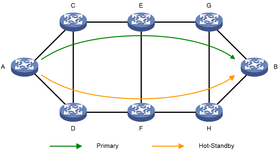
The hot spare function of SRv6 TE Policy can solve the aforementioned problems. The hot spare of SRv6 TE Policy refers to protecting the main candidate path through the backup candidate path. As shown in Fig. 25, if multiple candidate paths are under a SRv6 TE Policy, the candidate path with the highest privilege level is used as the main path and the second highest privilege level as the backup path. If all the forwarding paths corresponding to the SID list under the main path have faults, the traffic will immediately switchover to the backup candidate path, minimizing the impact on the business.
Figure 24 Hot Spare Diagram for SRv6 TE Policy
When the 'hot spare' function of SRv6 TE Policy and its interplay feature with SBFD are used together, SBFD can detect all the forwarding paths corresponding to the SID list in the two candidate paths with the highest and next highest 'privilege level' in SRv6 TE Policy. If all the forwarding paths corresponding to the SID list in the candidate path with the highest 'privilege level' fail, the 'traffic' will 'switchover' to the 'backup path'. Once the 'traffic' switches to the 'backup path', the primary and backup paths will be recalculated. The original 'backup path' will serve as the main path, and a new effective candidate path will be 'selected' as the new 'backup path'. If both the main and backup paths fail, SRv6 TE Policy will recalculate the primary and backup paths.
The intelligent policy routing function of SRv6 TE Policy
Introduction to the Intelligent Policy Routing Function of SRv6 TE Policy
As illustrated in Figure 26, a SRv6 TE Policy group is established between two nodes in the network, which contains multiple SRv6 TE Policy tunnels. The network quality of different SRv6 TE Policy tunnels may vary and change in real time. When traffic is forwarded within the SRv6 TE Policy group, users want the insured traffic to automatically switchover the path based on the network quality of SRv6 TE Policy tunnel, thereby ensuring that the standard of network quality is always met during the traffic forwarding process.
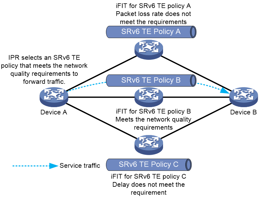
The Intelligent Policy Route (IPR) function of SRv6 TE Policy makes use of iFIT to carry out real-time quality checks on the network traffic of SRv6 TE Policy tunnels. Based on the results from iFIT, it excludes the SRv6 TE Policy tunnels that do not meet the network quality standard, identifies the SRv6 TE Policy tunnel with the highest privilege level, and directs traffic to be forwarded through this tunnel.
Figure 25 Illustration of the intelligent policy routing function in SRv6 TE Policy.
The intelligent policy routing mechanism of SRv6 TE Policy
The intelligent policy routing of SRv6 TE Policy is mainly completed by three collaborative functions: the iFIT measurement function of SRv6 TE Policy, the IPR routing function of SRv6 TE Policy, and the function of introducing business traffic into the IPR template.
The iFIT measurement function of the SRv6 TE Policy
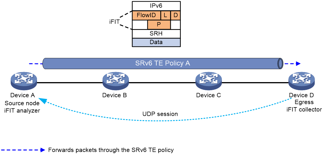
As shown in Figure 26, by deploying the iFIT function on the head node and tail node of the SRv6 TE Policy, the end-to-end packet loss rate, delay, and jitter of each SRv6 TE Policy are measured. The real-time packet loss rate, delay, and jitter data of each SRv6 TE Policy are then analyzed and calculated at the head node. The detailed workflow of the iFIT measurement function of the SRv6 TE Policy is as follows:
1. In the SRv6 TE Policy, the node head iFIT is set to "Analyzer" mode. Upon this setting, the head node automatically creates an iFIT instance and allocates a FlowID.
2. The head node of the SRv6 TE Policy, as the data transmitting end, wraps the original packets with a DOH header and SRH header carrying the iFIT option field when packets pass through the SRv6 TE Policy. The iFIT option field includes information such as the FlowID identifying the target stream, the loss measurement (LM) stain bit L, the delay measurement (DM) stain bit D, and the period identifier. The head node stains the loss measurement (LM) stain bit L and delay measurement (DM) stain bit D of packets according to the iFIT detection cycle of the SRv6 TE Policy. It counts the number of packets transmitted via the SRv6 TE Policy during a cycle based on packet staining information, and records the timestamps of the packets with the delay measurement (DM) stain bit D set to 1 sent from this SRv6 TE Policy during a cycle.
3. The working mode of the tail node iFIT is set to Collector, acting as the data receiver. It parses the iFIT option field in the packet, obtains information such as the iFIT detection period of the SRv6 TE Policy, and uses the packet coloring information to count the number of packets received from the SRv6 TE Policy within the iFIT detection period. It also records the timestamp of the delay measurement (DM) colored bit D set to 1 packet received from the SRv6 TE Policy within the iFIT detection period.
4. The tail node establishes a UDP session with the head node by receiving the source address of the message, and returns the counted message number and timestamp of the message to the head node via the UDP session according to the iFIT detection period of SRv6 TE Policy. The head node then analyzes and calculates the packet loss rate, delay, and jitter of the packets relayed through the SRv6 TE Policy.
Figure 26 Schematic Diagram of iFIT Measurement Function in SRv6 TE Policy
The routing function of SRv6 TE Policy's IPR
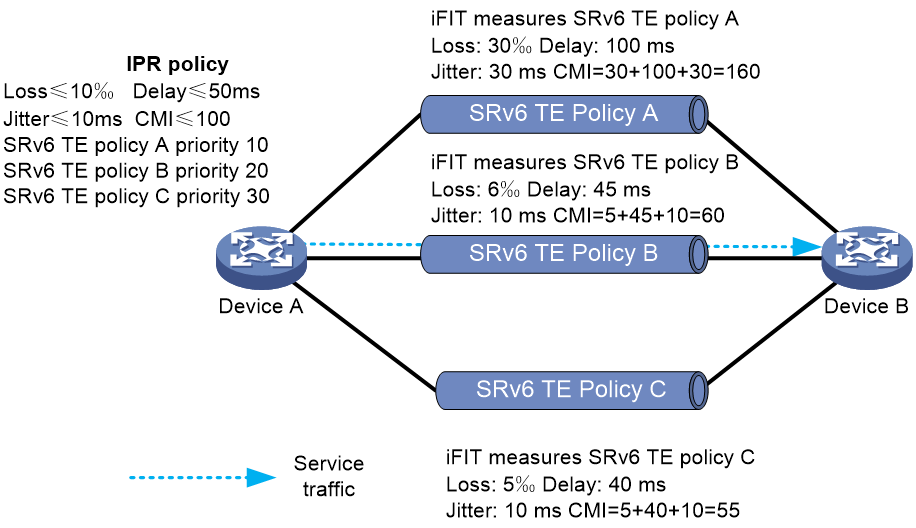
As shown in Figure 27, the head node of the SRv6 TE Policy periodically calculates the optimal SRv6 TE Policy based on the packet loss rate, latency, and jitter data of different SRv6 TE Policies measured by iFIT, as well as the routing privilege level of the SRv6 TE Policy.
For IPR routing, an IPR template needs to be defined. The IPR template represents a SRv6 TE Policy routing strategy based on the Service Level Agreement (SLA). The following can be defined in the IPR template:
· Different Service Level Agreement (SLA) standards, including business traffic latency standard, packet loss standard, jitter standard, and the Composite Measure Indicator (CMI) standard. Among them, the Composite Measure Indicator (CMI) equals latency (milliseconds) + jitter (milliseconds) + packet loss rate (‰).
· The mapping relationship between the Color value of the SRv6 TE Policy and the route selection privilege level. The smaller the number of the route selection privilege level, the higher the privilege level.
· The switchover time and fallback time parameters of the SRv6 TE Policy.
The detailed working mechanism of the IPR routing function is as follows:
1. The head node periodically performs path computation based on the IPR cycle. When calculating the optimal SRv6 TE Policy, it first checks if the latency, packet loss rate, jitter, and comprehensive metric of the SRv6 TE Policy fully meet the SLA standards defined in the IPR template. If any of these metrics do not meet the standard, then the SRv6 TE Policy cannot be considered as an alternative forwarding path in the calculation of the optimal SRv6 TE Policy.
2. Choose the SRv6 TE Policy with the lowest routing priority from the available SRv6 TE Policies as the optimal SRv6 TE Policy. If multiple different SRv6 TE Policies have the same routing priority, traffic can be load shared among these SRv6 TE Policies.
3. When the head node of SRv6 TE Policy calculates that the optimal SRv6 TE Policy is different from the currently used SRv6 TE Policy, in order to avoid business traffic switchover due to SRv6 TE Policy fluctuations, the business traffic will wait for a certain time before it switches to the optimal SRv6 TE Policy for forwarding.
|
|
NOTE: If the iFIT function of an SRv6 TE Policy fails to detect the delay, packet loss rate, jitter, and CMI parameters of a certain SRv6 TE Policy, but the SRv6 TE Policy is valid, it can still serve as an alternative path for path selection. |
Figure 27 Illustration of the IPR routing mechanism in SRv6 TE Policy
The function of introducing business traffic into the IPR template
The process of introducing business traffic into the IPR template is as follows:
1. Introduce the traffic into the SRv6 TE Policy group by the following methods.
The tunnel binding policy is matched according to the destination address of the packet, which is linked to the SRv6 TE Policy group.
After finding the SRv6 TE Policy group that matches the Color and Endpoint address with the Color extended community attribute and the next-hop address of the BGP route, iterate this BGP route to the SRv6 TE Policy group.
2. Set the forwarding type of the SRv6 TE Policy group to traffic forwarding based on TE Class ID.
3. Set up the mappings between the specified TE Class ID and IPR template. At this point, business traffic will dynamically select the optimal SRv6 TE Policy for forwarding from the SRv6 TE Policy group.
Application scenario of SRv6 TE Policy
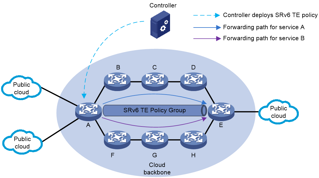
As shown in {Ref: Figure 29}, multiple cloud data centers are interconnected through the cloud backbone network, with various types of business traffic existing between them. Different businesses have different requirements for their SLAs (Service Level Agreements). In the cloud backbone network, multiple SRv6 TE Policies are deployed via the controller, forming a group of SRv6 TE Policies. For the SRv6 TE Policy tunnel, iFIT can be deployed to measure parameters such as packet loss rate, delay, and jitter, assessing the network quality of different SRv6 TE Policy tunnels.
At the source node A, business flows are classified through the QoS policy, identifying the DSCP values of different business types. After introducing the business traffic into the SRv6 TE Policy group, the traffic is forwarded to different SRv6 TE Policies based on the mapping relationship of DSCP->Color->SRv6 TE Policy. This fulfills the requirement for differentiated SLA of various businesses.
Figure 28 Application of SRv6 TE Policy in Cloud Backbone Network
Appendix
SRv6 Traffic Engineering Policy NLRI
SRv6 TE Policy NLRI
The SRv6 TE Policy NLRI is used to provide the network layer reachable information for SRv6 SID.
The message format of SRv6 TE Policy NLRI is shown as indicated in Figure 29.
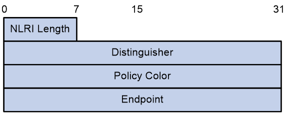
The SRv6 TE Policy NLRI package includes fields as shown in Table 1.
Table 1 Field Description Table for SRv6 TE Policy NLRI
|
Field Name |
Length |
Description |
|
NLRI Length |
8 bits |
The length of SRv6 Policy NLRI. |
|
Distinguisher |
32-bit |
An identifier uniquely identifies an SRv6 TE Policy. |
|
Policy Color |
32-bit |
The Color attribute of the SRv6 TE Policy. |
|
Endpoint |
128-bit |
The destination node address of the SRv6 TE Policy. |
Encapsulation Attribute of Tunnel
In the BGP Update message carrying the SRv6 TE Policy NLRI, the Tunnel Encapsulation Attribute also needs to be carried simultaneously. As shown in <field name="Ref" value="Table 2"/>, the relevant information of the SRv6 TE Policy is recorded by defining the following sub-TLVs in the Tunnel Encapsulation Attribute.
Table 2 Description Table of the Sub-TLV in Tunnel Encapsulation Attribute
|
The name of the TLV |
Description |
Carry Location |
|
Sub-TLV Preference |
Announce the privilege level of the candidate path. |
Tunnel Encapsulation Attribute |
|
Sub-TLV of SRv6 Binding SID |
Announce candidate path's BSID. |
Encapsulation Attribute of Tunnel |
|
Sub-TLV section of the list |
Announcement Segment List |
Tunnel Encapsulation Attribute |
|
Weight Sub-Type Length Value (Sub-TLV) |
Announce the weight of the Segment List. |
Segment List Sub-TLV |
|
Sub-Type Length Value (Sub-TLV) of Policy Candidate Path Name |
Announce the name of the candidate path. |
The attribute for Tunnel Encapsulation. |
Preference Sub-type Length Value (Sub-TLV)
The Preference Sub-TLV is used to carry the privilege level of the candidate path.
The message format of the Preference Sub-TLV is shown as in Figure 30.
Figure 30 Preference Sub-Type Length Value

The Preference Sub-TLV package contains fields as shown in Table 3, with reference field.
Table 3 Description Table for the Fields of Preference Sub-TLV
|
Field Name |
Length |
Description |
|
Type |
8 bits |
Type, with a value of 12. |
|
Length |
8 bits |
Length |
|
Flags |
8 bits |
Flag bit, currently undefined. |
|
Reserved |
8 bits |
The reserved value is set to 0. |
|
Preference |
32-bit |
The Preference value of the candidate path for SRv6 TE Policy. |
The Binding SID Sub-TLV is being defined
The Binding SID Sub-TLV is used to identify the BSID of the SRv6 TE Policy.
The message format of Binding SID Sub-TLV is shown as indicated in Figure 32.
Figure 31 Binding Sub-TLV of SID.
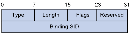
The Binding SID Sub-TLV package includes fields as shown in Table 4.
Table 4 Field Description Table of Binding SID Sub-TLV
|
Field Name |
Length |
Description |
|
Type |
8-bit |
Type, with a value of 13. |
|
Length |
8 bits |
Length |
|
Flags |
8 bits |
Flag bit, currently undefined. |
|
Reserved |
8 bits |
The reservation value is set to 0. |
|
Binding SID |
32-bit |
BSID Value |
Sub-TLV of Segment List
The Segment List Sub-TLV is used to carry the SID list of the candidate path.
The message format of the Segment List Sub-TLV is shown in Figure 33, as indicated by the field name "Ref" and its value.
Figure 32 The Sub-TLV of the Segment List
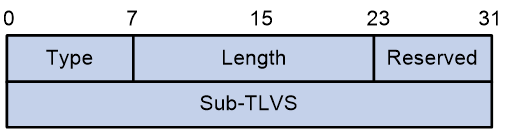
The Segment List Sub-TLV package includes fields as shown in the Table 5.
Table 5 Field Description Table for Segment List Sub-TLV
|
Field Name |
Length |
Description |
|
Type |
8 bits |
Type, with a value of 128. |
|
Length |
16 bits |
Length |
|
Reserved |
8 bits |
The reserved value is set to 0. |
|
Sub-TLVS |
32-bit |
· An optional Weight sub-TLV. · From zero to multiple Segment sub-TLVs. |
Sub-Type Length Value related to Weight
The Weight Sub-TLV is used to carry the weight of the SID list.
The message format of the Weight Sub-TLV is shown in Figure 33.
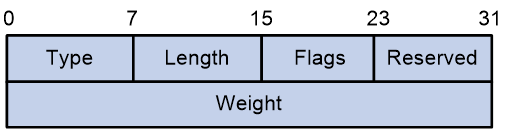
The Weight Sub-TLV contains fields as shown in Table 6.
Table 6 Field Description Table of Weight Sub-TLV
|
Field Name |
Length |
Description |
|
Type |
8 bits |
Type, with a value of 9. |
|
Length |
8 bits |
Length |
|
Flags |
8 bits |
Flag bit |
|
Reserved |
8 bits |
Reservation value, set to 0. |
|
Weight |
32-bit |
The weight value of the SID list. |
TE Policy NLRI of BGP-LS route
TE Policy NLRI
The BGP-LS aggregates topology information collected by the IGP protocol and sends it to the controller. This allows the controller to understand the entire network topology and calculate the optimal path based on it.
Before the introduction of BGP-LS, the controller used the flooding technique via IGP (OSPF, OSPFv3 OR IS-IS) protocol to collect topology information of the network. For collecting topology information across IGP domains, the IGP protocol needed to separately deliver the topology information of each domain to the controller. If multiple IGP protocols existed in the network, the controller also needed to support different IGP protocols. With the use of BGP-LS for collecting topology information, the controller only needs to support BGP-LS, which aggregates the topology information of each domain, making it more convenient.
To collect topology information, BGP-LS introduced a series of new NLRI (Network Layer Reachability Information) on top of the existing BGP, to carry link, node, and IPv4/IPv6 prefix-related information. This new type of NLRI is called Link-State NLRI. It is defined in RFC7752 as:
· Node NLRI with a Type value of 1.
· Link NLRI with a Type value of 2.
· The IPv4 Topology Prefix NLRI has a Type value of 3.
· The IPv6 Topology Prefix NLRI has a Type value of 4.
Based on the draft-ietf-idr-te-lsp-distribution, the information of TE Policy (including SRv6 TE Policy, SR-MPLS TE Policy, RSVP-TE, etc.) is also carried by the Link-State NLRI, and its NLRI Type value is 5. The format of NLRI's message is as follows:
Figure 34 The format of TE Policy NLRI
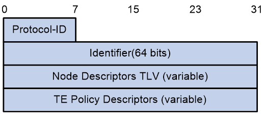
The TE Policy NLRI package includes fields as shown in Table 7.
Table 7 Field Description Table for TE Policy NLRI
|
Field Name |
Length |
Description |
|
Protocol-ID |
8 bits |
Protocol ID, BGP-LS learns the TE Policy information of a node by specifying the protocol. · 8: RSVP-TE · Segment Routing is the topic of discussion for number 9. |
|
Identifier |
64-bit |
Node Identifier (ID) |
|
Node Descriptors |
The length is variable. |
Description of the head node. |
|
Policy Descriptors of TE |
Variable length. |
The relevant information of TE Policy requires that the NLRI of SRv6 TE Policy must carry the SR Policy Candidate Path Descriptor TLV. |
SR Policy Candidate Path Descriptor TLV
The NLRI of the SRv6 TE Policy must carry an SR Policy Candidate Path Descriptor TLV. The format is as follows:
Figure 35 The format of the SR Policy Candidate Path Descriptor TLV
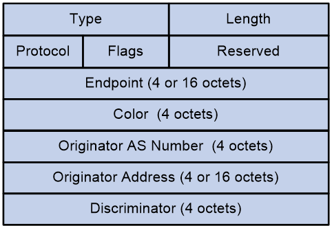
The SR Policy Candidate Path Descriptor TLV package includes fields as shown in Table 8.
Table 8 Field Description Table for TE Policy NLRI
|
Field Name |
Length |
Description |
|
Type |
16-bit |
Type, with a value of 554. |
|
Length |
16 bits |
The length, which can be either 24, 36, or 48 bytes. |
|
Protocol |
8 bits |
The protocol type for generating candidate paths, the values include: · PCEP · BGP · Static configuration (NETCONF or CLI configuration) |
|
Flags |
8 bits |
Flag bit |
|
Reserved |
8 bits |
The reserved space is entirely filled with zeros. |
|
Endpoint |
32 OR 128 bits |
The destination node of the SRv6 TE Policy. |
|
Color |
32-bit |
Color property of SRv6 TE Policy. |
|
The originating AS (Autonomous System) number. |
32-bit |
Generating the autonomous system (AS) number of the candidate path. |
|
Originator Address |
32 bit OR 128 bit |
The address of the device generating the candidate paths. |
|
Discriminator |
32-bit |
The identifier of the candidate path. |
In addition to the SR Policy Candidate Path Descriptor TLV, BGP-LS also defines various optional non-transitive properties for the TE Policy NLRI to announce information such as the candidate path state and various other details of the SRv6 TE Policy.
The specific expansion of BGP-LS for SRv6 TE Policy is as shown in Table 9.
Table 9 Expansion of BGP-LS for SRv6 TE Policy
|
Name of TLV |
Description |
Carrying location |
|
SR Binding SID TLV (Segment Routing Binding SID Type Length Value) |
Announce the BSID of the candidate path for SRv6 TE Policy, where BSID can either be a 4 byte MPLS label OR a 16 byte SRv6 SID. |
Policy NLRI of Traffic Engineering. |
|
Binding SID TLV for SRv6 |
Announce the BSID of the candidate path for SRv6 TE Policy, where the BSID is fixed at 16 bytes. |
TE Policy NLRI: Traffic Engineering Policy Network Layer Reachability Information |
|
The State of Candidate Path in SR TLV |
Announce (Annc) the properties and state information (Info) of the SRv6 TE Policy candidate path. |
TE Policy NLRI |
|
SR Policy Name Type Length Value |
Announce the name of the SRv6 TE Policy. |
The NLRI (Network Layer Reachability Information) policy of Traffic Engineering. |
|
TLV of SR Candidate Path Name. |
Announce the name of the SRv6 TE Policy candidate path. |
TE Policy NLRI |
|
SR Candidate Path Constraints TLV |
Announce the constraint conditions for SRv6 TE Policy candidate paths, which are typically applied to candidate paths dynamically calculated by the head end. |
The NLRI (Network Layer Reachability Information) of Traffic Engineering Policy. |
|
SR Affinity Constraint Sub-TLV |
Announce the affinity properties of the SRv6 TE Policy candidate path. |
TLV for SR Candidate Path Constraints |
|
Sub-TLV Constraint for SR SRLG |
Announce the value of the shared risk link group for the candidate path of the SRv6 TE Policy. |
TLV Constraints on SR Candidate Path |
|
Sub-TLV for SR Bandwidth Constraint |
Announce (Annc) the bandwidth requirements of the SRv6 TE Policy candidate path. |
SR Candidate Path Constraints TLV |
|
Sub-TLV Constraint for SR Disjoint Group |
Announce the non-overlapping constraint group identify for the SRv6 TE Policy candidate path. |
SR Candidate Path Constraints TLV |
|
Bidirectional Group Constraint Sub-TLV in SR |
Announce the bidirectional group identification of the SRv6 TE Policy candidate path. |
The TLV (Type, Length, Value) for constraints on the SR (Segment Routing) Candidate Path. |
|
Sub-TLV Restriction for SR Metric |
Announce the metric values of the SRv6 TE Policy candidate path. |
The TLV of SR Candidate Path Constraints. |
|
SR Segment List TLV |
Announce the SID list of candidate paths for SRv6 TE Policy. |
TE Policy NLRI |
|
Sub-TLV Segment of SR |
Announce the SID value from the list of SRv6 TE Policy candidate path's SID. |
TLV of SR Segment List |
Source Routing Binding Segment Identifier Type Length Value
The SR Binding SID TLV is used to announce the BSID of the SRv6 TE Policy candidate path.
Figure 36 The format of SR Binding SID TLV
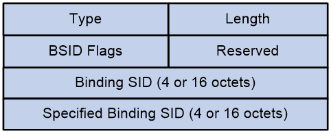
The SR Binding SID TLV package includes fields as shown in Table 10.
Table 10 Field Description Table of SR Binding SID TLV
|
Field Name |
Length |
Description |
|
Type |
16-bit |
Type, with a value of 1201. |
|
Length |
16 bits |
Length |
|
BSID Flags |
16 bits |
Candidate path BSID's flag bit, with a length of 2 bytes: · D-Flag: Identifies if this BSID is an SRv6 SID or an MPLS label. · B-Flag: Identifies whether the BSID value is allocated properly. · U-Flag: Identifies whether the Specified BSID is available. · L-Flag: Identifies if the allocation is from the SRLB label section or from the dynamic label pool. · F-Flag: This indicates that the specified BSID is not available and needs dynamic allocation. |
|
Reserved |
16 bits |
The reserved value is set to 0. |
|
Binding SID |
32-bit OR 128-bit |
The term refers to the BSID value that is actually used or allocated. This value might be predefined, making the BSID available upon specification, or it may be dynamically allocated. |
|
Specified Binding Security Identifier (SID) |
32 OR 128 bits |
The specified BSID value is indicated. If no BSID is designated, it will display as 0. Even if the specified BSID value is unavailable, it will still be displayed. |
Binding SRv6 SID TLV
The SRv6 Binding SID TLV is used to announce (Annc) the BSID of the candidate path for SRv6 TE Policy.
Figure 37 The format of SRv6 Binding SID TLV.
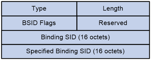
The SRv6 Binding SID TLV package includes fields as shown in Table 11.
Table 11 Field description table for SRv6 Binding SID TLV
|
Field Name |
Length |
Description |
|
Type |
16 bits |
Type, with a value of 1212. |
|
Length |
16-bit |
Length |
|
BSID Flags |
16-bit |
The flag bit of the candidate path BSID, with a length of 2 bytes. · B-Flag: Identifies if the BSID value is allocated normally. · U-Flag: Identifies whether the specified BSID is available. · F-Flag: Indicates the specified BSID is not available, requiring dynamic allocation. |
|
Reserved |
16-bit |
The reserved value, set to 0. |
|
Binding SID |
128-bit |
This represents the actual used or allocated BSID value. This value could be pre-specified; once specified, the BSID becomes available. Alternatively, it might be dynamically allocated. |
|
Specified Binding SID |
128 bits |
The identified BSID value is displayed. If the BSID is not specified, it will show as 0. Even if the specified BSID value is not available, it will still be displayed. |
SR Candidate Path State TLV
The SR Candidate Path State TLV is used to announce the properties and state information of the SRv6 TE Policy candidate path.
Figure 38 The format of the SR Candidate Path State TLV
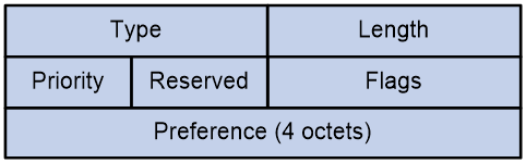
The SR Candidate Path State TLV package includes fields as shown in Table 12.
Table 12 Field Description Table of SR Candidate Path State TLV
|
Field Name |
Length |
Description |
|
Type |
16 bits |
Type, with a value of 1202. |
|
Length |
16 bits |
Length |
|
Priority |
8 bits |
The precedence order of path selection for recalculation when topology changes. |
|
Reserved |
8 bits |
Reservation value, set to 0. |
|
Flags |
16 bits |
The state and properties information of candidate paths. · S-Flag: Identify (ID) the candidate path's shutdown state. · A-Flag: Identifies whether the candidate path is in the primary use state. · B-Flag: Identifies whether the candidate path is in standby state. · E-Flag: Identifies whether the candidate path has been through an validity assessment. · V-Flag: Identifies whether the candidate path has at least one valid SID list. · O-Flag: Identifies whether the candidate path is calculated based on the next hop template as required by the ODN. · D-Flag: Identifies whether the candidate path is delegated to the PCE/controller for calculation. · C-Flag: Identifies whether the candidate path is issued by the PCE/controller. · I-Flag: It identifies the candidate path as the preferred candidate path. When there are no other candidate paths for SRv6 TE Policy, and this candidate path fails, the function to discard the traffic is activated. · T-Flag: Indicates that the SRv6 TE Policy on the head node can be used for label stitching. · U-Flag: Identifies that the SRv6 TE Policy this candidate path belongs to is in the state of discarding traffic when all candidate paths fail. |
|
Preference |
32-bit |
The privilege level of the candidate path. |
Subnet Route Policy Name Tag-Length-Value
The SR Policy Name TLV is used to announce the name of the SRv6 TE Policy.
Figure 39 The format of the SR Policy Name TLV
![]()
The SR Policy Name TLV package includes fields as shown in Table 13.
Table 13 SR Policy Name TLV Field Description Table
|
Field Name |
Length |
Description |
|
Type |
16 bits |
Type, with a value of 1213. |
|
Length |
16 bits |
Length |
|
Policy Name for SR |
Variable |
The name of the SRv6 TE Policy. |
SR Candidate Path Name TLV
The SR Candidate Path Name TLV is used to announce the names of the SRv6 TE Policy candidate paths.
Figure 40 The format of the SR Candidate Path Name TLV
![]()
The SR Candidate Path Name TLV package includes fields as shown in the Table 14.
Table 14 Field Description Table for SR Candidate Path Name TLV
|
Field Name |
Length |
Description |
|
Type |
16 bits |
Type, with a value of 1203. |
|
Length |
16 bits |
Length |
|
Candidate Path Name |
Variable |
The name of the SRv6 TE Policy candidate path. |
TLV for SR Candidate Path Constraints
The SR Candidate Path Constraints TLV is used to announce the condition constraints of the SRv6 TE Policy candidate path, which are generally applied to the dynamically calculated candidate path by the head-end.
Figure 41 The format of SR Candidate Path Constraints TLV
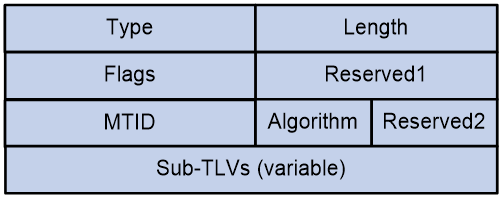
The SR Candidate Path Constraints TLV package includes fields as shown in Table 15.
Table 15 Field Description Table of SR Candidate Path Constraints TLV
|
Field Name |
Length |
Description |
|
Type |
16 bits |
Type, with a value of 1204. |
|
Length |
16-bit |
Length |
|
Flags |
16-bit |
The constraint conditions of the candidate path. · D-Flag: Identifies whether the forwarding plane of the candidate path is based on SRv6 or SR-MPLS. · P-Flag: Identifies the preferred protection type SID in the candidate path's SID list. · U-Flag: Identifies the preferred non-protected SID in the SID list of candidate paths. · A-Flag: Identifies whether the SID in the candidate path's SID list belongs to the specified Flex-Algo Algorithm. · T-Flag: Identifies if the SID in the candidate path's SID list belongs to a specified topology. · S-Flag: Identifies whether the SID list of the candidate path strictly requires the SID to be a protection type SID or a non-protection type SID, not a preference. · F-Flag: This identifier indicates that the calculated path for the candidate is fixed. Unless intervened by an operator, it will not be modified. |
|
Reserved1 |
16 bits |
The reserved value is set to 0. |
|
MTID |
16 bits |
If the T-Flag is set, it indicates that only the specified IGP topology ID can be used to calculate the candidate path. If the T-Flag is not set, it indicates that the specified IGP topology ID is preferred for calculating candidate paths. If calculation is not possible, other IGP topology IDs can be used to calculate candidate paths. |
|
Algorithm |
8 bits |
Designate the Flex-Algo algorithm ID. If the A-Flag is set, it indicates that only the specified Flex-Algo algorithm can be used to calculate the candidate path. If the A-Flag is not set, it means that the specified Flex-Algo algorithm should be prioritized for calculating the candidate path. If calculation is not possible, other Flex-Algo algorithms can be used to calculate the candidate path. |
|
Reserved2 |
8 bits |
The reservation value is set to 0. |
|
Sub-TLVs |
Variable. |
The TE constraint condition Sub-TLV of the candidate path. |
SR Segment List TLV
The SR Segment List TLV is used to announce a SID list in a candidate path of the SRv6 TE Policy.
Figure 42 The format of SR Segment List TLV
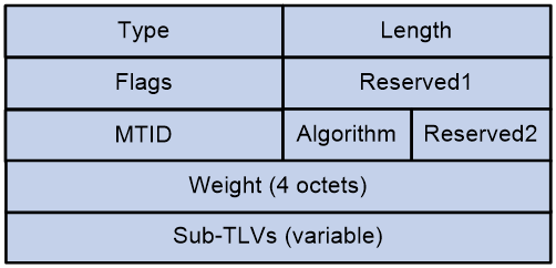
The SR Segment List TLV package includes fields as shown in Table 16.
Table 16 Field description table of SR Segment List TLV
|
Field Name |
Length |
Description |
|
Type |
16 bits |
Type, with a value of 1205. |
|
Length |
16 bits |
Length |
|
Flags |
16 bits |
The state information of the SID list. · D-Flag: Identifies whether the SID list is composed of SRv6 SID group or MPLS label group. · E-Flag: Identifies whether the SID list is an explicitly specified static path or a dynamic path. · C-Flag: If set, it indicates that a SID list has been calculated when the SID list is a dynamic path. If the SID list is a statically specified explicit path, it will always be set. · V-Flag: Indicates that the SID list has passed path validation, OR the validation function for the SID list has not been set. · The R-Flag indicates whether the first SID in the list is reachable. · F-Flag: Indicates the dynamic calculation of the SID list has failed. · A-Flag: It indicates that all SIDs in the list belong to a single Flex-Algo algorithm. · T-Flag: Indicates that all SIDs in the list belong to a single topology instance. · M-Flag: Indicates that due to the failure of BFD and other checks, the SID list is unmounted from the forwarding entry. |
|
Reserved1 |
16-bit |
The reserved value is set to 0. |
|
MTID |
16 bits |
If the T-Flag is set, it indicates that only the specified IGP topology ID can be used to calculate the SID list. If the T-Flag is not set, it means that the specified IGP topology ID should be used as a priority to calculate the SID list. If it can't be calculated, other IGP topology IDs can be used to calculate the SID list. |
|
Algorithm |
8 bits |
Assign the Flex-Algo algorithm ID. If the A-Flag is set, it signifies that only the specified Flex-Algo algorithm can be used to calculate the candidate path. If the A-Flag is not set, it indicates a preference for using the specific Flex-Algo algorithm to calculate the candidate path. If it's unable to calculate, other Flex-Algo algorithms can be utilized to calculate the candidate path. |
|
Reserved2 |
8 bits |
The reserved value, set to 0. |
|
Weight |
32-bit |
The weight value of the SID list. |
|
Sub-TLV |
Variable. |
Sub-TLV of the SID list. |
Related documentation
· draft-ietf-spring-segment-routing-policy-09
· draft-ietf-idr-te-lsp-distribution
· RFC9256