- Released At: 12-05-2025
- Page Views:
- Downloads:
- Table of Contents
- Related Documents
-
EVPN Technology White Paper
Copyright © 2024 New H3C Technologies Co., Ltd. All rights reserved.
No part of this manual may be reproduced or transmitted in any form or by any means without prior written consent of New H3C Technologies Co., Ltd.
Except for the trademarks of New H3C Technologies Co., Ltd., any trademarks that may be mentioned in this document are the property of their respective owners.
The content in this article is general technical information, some of which may not be applicable to the product you purchased.
Contents
Ethernet auto-discovery route (RT-1)
MAC/IP advertisement route (RT-2)
Inclusive multicast Ethernet tag route (RT-3)
IP prefix advertisement route (RT-5)
Selective multicast Ethernet tag route (RT-6)
Extended community attributes of BGP EVPN routes
ES-Import Route Target Extended Community
MAC Mobility Extended Community
Default Gateway Extended Community
Encapsulation Type Extended Community
VPN Target Extended Community (Route Target)
EVPN VXLAN control plane working mechanism
Establishment of VXLAN tunnels and BUM broadcast table
Advertisement and learning of MAC/IP advertisement routes
Advertisement and learning of external routes
EVPN VXLAN data plane working mechanism
Centralized gateway forwarding
Distributed gateway symmetrical IRB
Distributed gateway asymmetrical IRB
Support of EVPN VXLAN for multicast
EVPN data center interconnection
Configuring EVPN on SDN controller
EVPN VPLS control plane working mechanism
MAC address learning, aging, and withdrawal
EVPN VPLS data plane working mechanism
EVPN VPWS control plane working mechanism
Public network tunnel establishment
EVPN VPWS data plane working mechanism
LDP PW or static PW access to EVPN PW
EVPN L3VPN control plane working mechanism
Route advertisement from the local CE to the ingress PE
Route advertisement from the ingress PE to the egress PE
Route advertisement from the egress PE to the remote CE
EVPN L3VAN data plane working mechanism
Interconnection between BGP/MPLS L3VPN and EVPN L3VPN
Overview
Technical background
As data center business is increasingly growing, user demands are continuously rising, and the scale and functions of data centers are becoming more complex, making management increasingly difficult. Considering disaster recovery, multi-location deployment of enterprise branches, and improving resource utilization, enterprises may deploy their data center networks across different physical sites. Consequently, how to interconnect these data center sites, reduce management costs, and flexibly expand data center services becomes an important task for enterprise data centers.
Ethernet Virtual Private Network (EVPN) is a Layer 2 network interconnection technology based on the overlay technology, which offers the advantages of simple deployment and strong scalability. EVPN uses the MP-BGP protocol to advertise the reachability of MAC/IP addresses and multicast information, and it conducts Layer 2/3 packet forwarding through generated MAC table entries and routing table entries to achieve Layer 2 network interconnection, effectively fulfilling the needs of users for large-scale data center networks.
Currently, EVPN is not only widely used in data center networks but also has certain applications in campus access networks, wide area networks, and carrier networks.
Protocol framework
EVPN defines a general control plane, and the data plane can use different encapsulation technologies, as shown in Figure 1. Currently, Comware supports VXLAN, MPLS, and IPv6 Segment Routing (SRv6) as data plane options.
Figure 1 EVPN protocol framework
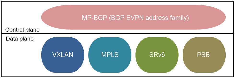
EVPN technologies for different data planes are as follows:
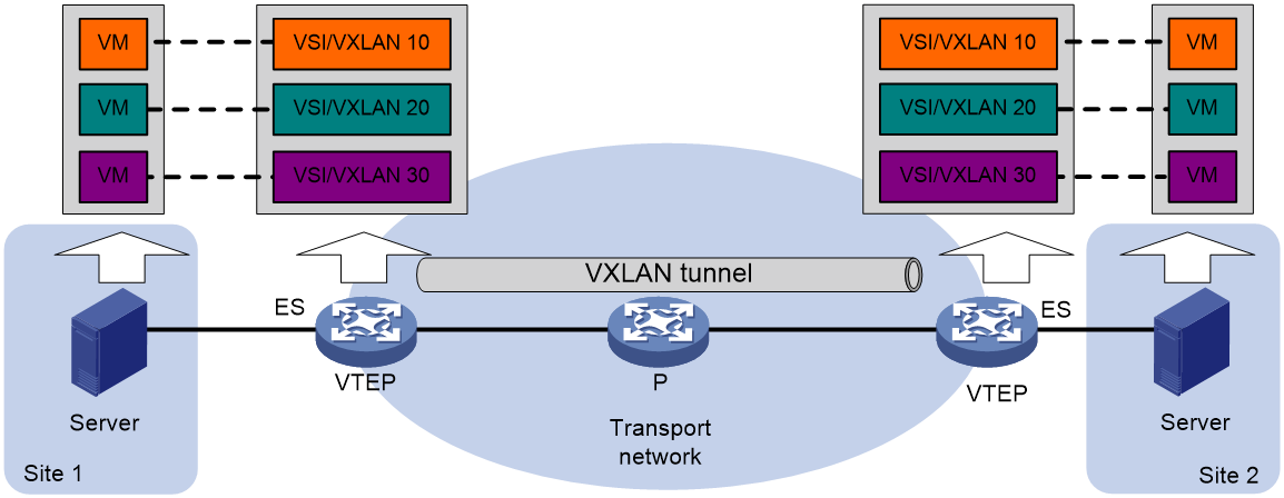
· EVPN VXLAN: EVPN VXLAN uses the VXLAN technology for traffic forwarding in the data plane.
The transport edge devices are VXLAN tunnel endpoints (VTEPs). All EVPN VXLAN processing is performed on VTEPs. EVPN VXLAN establishes VXLAN tunnels between VTEPs, transparently transmitting Layer 2 data packets to interconnect sites at Layer 2.
You can deploy an EVPN gateway in the EVPN VXLAN network to provide Layer 3 interconnection for different subnets in the same tenant and for tenant subnets and the external network.
For more information about EVPN VXLAN, see "EVPN VXLAN."
Figure 2 EVPN VXLAN network model
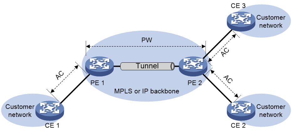
· EVPN VPLS: The data plane uses MPLS encapsulation to implement point-to-multipoint Layer 2 interconnection.
In EVPN VPLS networking, the customer network side device CE accesses the provider network side device PE through an AC, and a PW is established between the PEs through BGP EVPN routing. PE forwards messages by looking up the MAC address table, enabling Layer 2 communication for users in a point-to-multipoint manner.
For more information about EVPN VPLS, see "EVPN VPLS."
Figure 3 EVPN VPLS network model
· EVPN VPWS: The data plane uses MPLS encapsulation to implement point-to-point Layer 2 interconnection.
In EVPN VPWS networking, the customer network device CE connects to the provider network device PE through an AC. The PEs establish EVPN PWs through BGP EVPN routing. Use a cross-connect on the PE to associate the AC with the EVPN PW, enabling point-to-point Layer 2 interconnection.
For more information about EVPN VPWS, see "EVPN VPWS."
Figure 4 EVPN VPWS network model

· EVPN VPLS over SRv6: The data plane uses SRv6 encapsulation to implement point-to-multipoint Layer 2 interconnection.
· EVPN VPWS over SRv6: The data plane uses SRv6 encapsulation to implement point-to-point Layer 2 interconnection.
This document only introduces EVPN VXLAN, EVPN VPLS, and EVPN VPWS. For more information about EVPN VPLS over SRv6 and EVPN VPWS over SRv6, see SRv6 Technology White Paper.
Technical benefits
EVPN not only inherits the advantages of MP-BGP and VXLAN/MPLS, but also provides new features. EVPN provides the following benefits:
· Configuration automation—MP-BGP automates VTEP/PE discovery, VXLAN tunnel/PW establishment, and VXLAN tunnel assignment to ease deployment.
· Separation of the control plane and the data plane—EVPN uses MP-BGP to advertise host reachability information in the control plane and uses VXLAN or MPLS to forward traffic in the data plane.
· Point-to-point and point-to-multipoint connection—Layer 2 frames are transmitted transparently across the IP or MPLS transport network between sites after they are encapsulated into VXLAN packets or MPLS packets.
Compared to the traditional VPLS technology, EVPN has the following benefits:
· EVPN supports complete multi-homing deployments. All deployments support load sharing and primary/backup modes.
· EVPN uses MP-BGP in the control plane to advertise MAC and IP reachability between sites instead of learning this information in the data plane. This mechanism brings the following benefits for the network devices to manage MAC and IP addresses as flexibly as they manage routes:
¡ Provides good scalability.
¡ Ensures isolation between hosts or between VMs.
¡ Addresses the load sharing issue in node or network multihoming scenarios, and accelerates network convergence upon a link or node failure.
· EVPN provides integrated routing and bridging (IRB) by using MP-BGP to advertise both Layer 2 and Layer 3 host reachability information.
· EVPN uses route reflectors to avoid full mesh topology, decreasing the network deployment complexity.
BGP EVPN routes
To support EVPN, MP-BGP defines a new subaddress family under the L2VPN address family, the EVPN address family, and specifies the EVPN network layer reachability information (NLRI) for this address family, which is the EVPN route. The address family number used by the EVPN subaddress family is: AFI=25, SAFI=70.
In an EVPN network, VTEP/PE can establish both IBGP and EBGP peers.
· To simplify the full connection setup when establishing IBGP peers, deploy a route reflector (RR). All VTEP/PEs establish BGP peer relationships only with the RR. The RR discovers and receives the BGP connections initiated by VTEP/PE, forming a customer list, and reflects the routes received from a VTEP/PE to all other VTEP/PEs.
· RR is not required when establishing EBGP peers. BGP automatically transmits the EVPN messages received from EBGP peers to other EBGP and IBGP peers.
Ethernet auto-discovery route (RT-1)
Ethernet auto-discovery routes are used to advertise ES information in multihomed sites and advertise service ID information in an EVPN VPWS network.
Ethernet auto-discovery routes include the following:
· Ethernet Auto-discovery Per ES routes: Mainly used for fast convergence, redundancy mode, and split horizon in multihoming networks.
· Ethernet Auto-discovery Per EVI Routes: Mainly used for aliasing and backup path in multihoming networks.
Figure 5 Ethernet auto-discovery route packet format
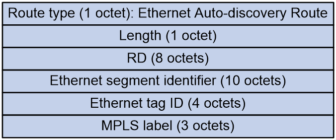
As shown in Figure 5, the Ethernet auto-discovery route includes the following fields:
· Route Distinguisher (RD): RD of the EVPN instance.
· Ethernet Segment Identifier (ESI): Segment identifier for the Ethernet link between VTEP/PE and CE. When the same site CE is multi-homed to different PEs through different links, these links form an Ethernet Segment (ES), and are identified by a common ESI.
· Ethernet Tag ID:
¡ For the Ethernet Auto-discovery Per ES routes, this field is set to all-F.
¡ For the Ethernet Auto-discovery Per EVI routes, this field takes different values in different types of networks:
- In EVPN VPLS and EVPN VXLAN, this field is the tag ID of VSI instance, the VLAN of the access AC, or all zeros.
- In EVPN VPWS, this field is the local service ID.
· MPLS label:
¡ For Ethernet Auto-discovery Per ES routes, this field is set to 0.
¡ For Ethernet Auto-discovery Per EVI routes, this field has different values in different data encapsulation types:
- In VXLAN encapsulation, it is the VXLAN ID.
- In MPLS encapsulation, it is the MPLS label.
- In SRv6 encapsulation, it is combined with the SRv6 TLV to represent the SID.
MAC/IP advertisement route (RT-2)
MAC/IP advertisement routes are used to advertise MAC address and host route information (ARP and ND information).
Figure 6 MAC/IP advertisement route packet format
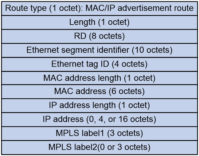
As shown in Figure 6, the MAC/IP advertisement route includes the following fields:
· RD: RD of the EVPN instance.
· Ethernet section identifier: Segment identifier for the Ethernet link between VTEP/PE and CE.
· Ethernet tag ID: Tag ID of the VSI instance, VLAN of the access AC, or all zeros.
· MAC address length.
· MAC address.
· IP address length.
· IP address.
· MPLS label1: In different data encapsulation types, this field has different values:
¡ In VXLAN encapsulation, it is the VXLAN ID.
¡ In MPLS encapsulation, it is the MPLS label.
¡ In SRv6 encapsulation, it is combined with the SRv6 TLV to represent the SID.
· MPLS label2: Identifier used for Layer 3 traffic forwarding. In different data encapsulation types, this field has different values:
¡ In VXLAN encapsulation, it is the L3VNI.
¡ In MPLS encapsulation, it is not supported.
¡ In SRv6 encapsulation, it is combined with the SRv6 TLV to represent the SRv6 SID used by the distributed SRv6 gateway for Layer 3 traffic forwarding.
Inclusive multicast Ethernet tag route (RT-3)
Inclusive multicast Ethernet tag routes, also known as IMET routes, are used in EVPN VXLAN networks to advertise VTEP and VXLAN information for autodiscovery of VTEPs, automatic VXLAN tunnel establishment, and automatic association of VXLAN with VXLAN tunnel. In EVPN VPLS networks, IMET routes are used to advertise PE information for autodiscovery of PEs and automatic establishment of PWs.
Figure 7 IMET route packet format
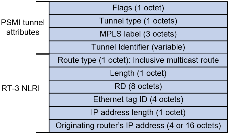
As shown in Figure 7, an IMET route carries Provider Multicast Service Interface (PSMI) tunnel attributes:
· Flags.
· Tunnel type:
¡ 0: No tunnel information present.
¡ 1: RSVP-TE P2MP LSP.
¡ 2: mLDP P2MP LSP.
¡ 3: PIM-SSM Tree.
¡ 4: PIM-SM Tree.
¡ 5: BIDIR-PIM Tree.
¡ 6: Ingress Replication.
¡ 7: mLDP MP2MP LSP.
· MPLS label: MPLS label, VXLAN ID, or SID encapsulated for Broadcast/Unknown unicast/Unknown Multicast (BUM) traffic forwarding.
· Tunnel Identifier: IP address of the tunnel remote end when the tunnel type is Ingress Replication.
An IMET route includes the following fields:
· RD: RD of the EVPN instance.
· Ethernet tag ID: VLAN of the access AC or all zeros.
· IP address length: Mask length of the IP address originating the route.
· Originating router's IP address: IP address of the originating VTEP or PE. The value is the BGP router ID.
Ethernet segment route (RT-4)
Ethernet segment routes are used to advertise ES and VTEP information. This enables the discovery of other members in a multi-homed redundancy group connected to the same ES, as well as the election of a DF among the redundancy group.
Figure 8 Ethernet segment route packet format
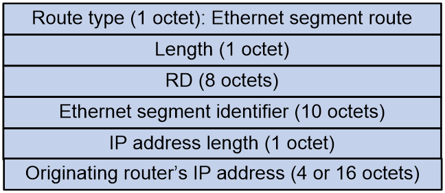
As shown in Figure 8, the Ethernet segment route includes the following fields:
· RD: Automatically generated based on the IP address of VTEP/PE, for example X.X.X.X:0.
· Ethernet section identifier: Segment identifier for the Ethernet link between VTEP/PE and CE.
· IP address length: Mask length of the IP address from which the route originates.
· Originating router's IP address: IP address of the VTEP or PE that originates the route. It is the BGP router ID.
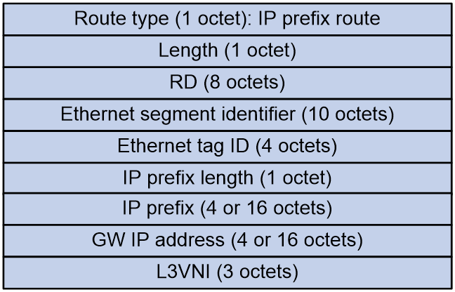
IP prefix advertisement route (RT-5)
IP prefix advertisement routes are used to advertise BGP IPv4 unicast routes or BGP IPv6 unicast routes in the form of IP prefixes.
Figure 9 IP prefix advertisement route packet format
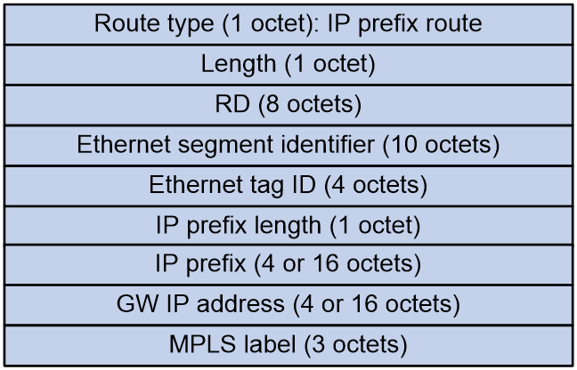
As shown in Figure 9, the IP prefix advertisement route includes the following fields:
· RD: RD of the VPN instance/public instance EVPN address family.
· Ethernet segment identifier: Segment identifier for the Ethernet link between VTEP/PE and CE.
· Ethernet tag ID: It is set to all zeros.
· IP prefix length: Length of the IP prefix mask.
· IP prefix: IP prefix address.
· GW IP address: Default gateway address.
· L3VNI: In different data encapsulation types, this field has different values:
¡ In VXLAN encapsulation, it is the L3VNI used for Layer 3 traffic forwarding.
¡ In MPLS encapsulation, it is the MPLS label.
¡ In SRv6 encapsulation, it is the SID used for Layer 3 traffic forwarding.
Selective multicast Ethernet tag route (RT-6)
Selective multicast Ethernet tag routes are used to advertise tenant IGMP multicast group information.
Figure 10 Selective multicast Ethernet tag route packet format
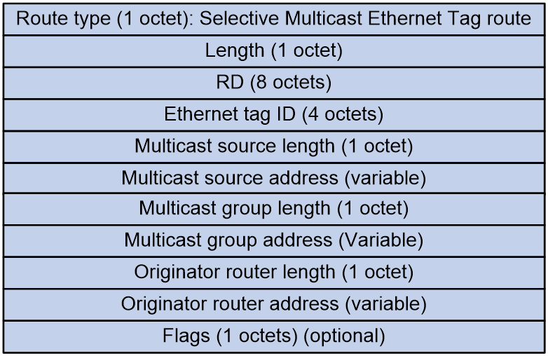
As shown in Figure 10, a selective multicast Ethernet tag route includes the following fields:
· RD: RD of the EVPN instance.
· Ethernet tag ID: This field is set to all zeros.
· Multicast source length: IP address length of the multicast source that the tenant joins, 32 bits for IPv4 and 128 bits for IPv6.
· Multicast source address: Address of the multicast source joined by the tenant.
· Multicast group length: Length of the IP address for the multicast group that the tenant joins, 32 bits for IPv4 and 128 bits for IPv6.
· Multicast group address: Address of the multicast group joined by the tenant.
· Originator router length: Length of the IP address originating the route, 32 bits for IPv4 and 128 bits for IPv6.
· Originator router address: IP address of the VTEP or PE originating the route, which is the BGP router ID.
· Flags: This field varies by the Multicast group address field:
¡ If the Multicast group address is an IPv4 address:
- Bit 7 indicates if IGMP version 1 is supported.
- Bit 6 indicates whether IGMP version 2 is supported.
- Bit 5 indicates whether IGMP version 3 is supported.
- Bit 4 indicates the mode of the carried (S, G), with a value of 1 representing Exclude mode, and a value of 0 representing Include mode. This bit is only valid when bit 5 has a value of 1, and is ignored when bit 5 has a value of 0.
¡ If the Multicast group address is an IPv6 address:
- Bit 7 indicates whether MLD version 1 is supported.
- Bit 6 indicates whether MLD version 2 is supported.
- Bit 5 is fixed at 0.
- Bit 4 indicates the mode of the carried (S, G), with a value of 1 representing Exclude mode, and a value of 0 representing Include mode. This bit is only valid when bit 6 has a value of 1. If bit 6 has a value of 0, this bit is ignored.
IGMP Join Synch Route (RT-7)
IGMP Join Synch Routes are used to synchronize the IGMP join multicast group information among multi-homed members.
Figure 11 IGMP Join Synch Route packet format
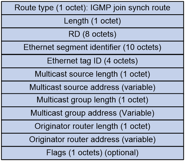
As shown in Figure 11, the IGMP Join Synch Route includes the following fields:
· RD: RD of the EVPN instance.
· Ethernet segment identifier: Segment identifier for the Ethernet link between VTEP/PE and CE.
· Ethernet tag ID: VLAN of the access AC.
· Multicast source length: IP address length of the multicast source joined by the tenant. An IP address of 32 bits denotes IPv4 and 128 bits denotes IPv6.
· Multicast source address: Address of the multicast source that the tenant has joined.
· Multicast group length: Length of the IP address of the multicast group that the tenant joins, 32 bits for IPv4 and 128 bits for IPv6.
· Multicast group address: Address of the multicast group joined by the tenant.
· Originator router length: Length of the IP address that initiates the route, where 32 represents IPv4 and 128 represents IPv6.
· Originator router address: IP address of the VTEP or PE that initiates the route. It is the BGP router ID.
· Flags: The content varies by the Multicast group address field.
¡ If the Multicast group address is an IPv4 address:
- Bit 7 indicates whether IGMP version 1 is supported.
- Bit 6 indicates whether IGMP version 2 is supported.
- Bit 5 indicates whether IGMP version 3 is supported.
- Bit 4 indicates the mode of the carried (S, G), with a value of 1 denoting Exclude mode and a value of 0 denoting Include mode. This bit is only valid when bit 5 has a value of 1. When bit 5 is 0, this bit is ignored.
¡ If the Multicast group address is an IPv6 address:
- Bit 7 indicates whether MLD version 1 is supported.
- Bit 6 indicates whether MLD version 2 is supported.
- Bit 5 is fixed at 0.
- Bit 4 indicates the mode of the (S, G) carried, with a value of 1 denoting Exclude mode and a value of 0 denoting Include mode. This bit is only valid when bit 6 has a value of 1. If bit 6 has a value of 0, this bit is ignored.
IGMP Leave Synch Route (RT-8)
IGMP Leave Synch Routes are used to advertise the IGMP leaving multicast group information among multi-homed members to withdraw the corresponding IGMP join synch routes.
Figure 12 IGMP Leave Synch Route packet format
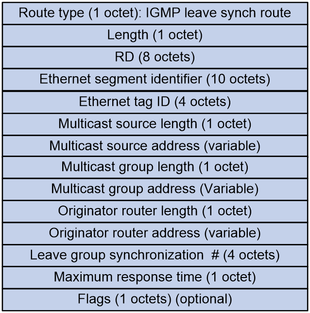
As shown in Figure 12, the IGMP Leave Synch Route includes the following fields:
· RD: RD of the EVPN instance.
· Ethernet segment identifier: Segment identifier for the Ethernet link between VTEP/PE and CE.
· Ethernet tag ID: VLAN of the access AC.
· Multicast source length: The length of the IP address of the multicast source that the tenant has joined, 32 bits for IPv4 and 128 bits for IPv6.
· Multicast source address: Address of the multicast source joined by the tenant.
· Multicast group length: IP address length of the multicast group joined by the tenant, where 32 represents IPv4 and 128 represents IPv6.
· Multicast group address: Address of the multicast group joined by the tenant.
· Originator router length: Length of the IP address of the originating router, with 32 indicating IPv4 and 128 indicating IPv6.
· Originator router address: IP address of the VTEP or PE initiating the route, with the value being the BGP router ID.
· Leave group synchronization: Sequence number for tenant departure from a multicast group.
· Maximum response time: Maximum response time indicated in the advertisement.
· Flags: The content varies by the Multicast group address field.
¡ If the Multicast group address is an IPv4 address:
- Bit 7 indicates whether IGMP version 1 is supported.
- Bit 6 indicates whether IGMP version 2 is supported.
- Bit 5 indicates whether IGMP version 3 is supported.
- Bit 4 indicates the mode of the carried (S, G). A value of 1 represents Exclude mode, while a value of 0 represents Include mode. This bit is only valid when bit 5 has a value of 1. If bit 5 has a value of 0, this bit is ignored.
¡ If the Multicast group address is an IPv6 address:
- Bit 7 indicates whether MLD version 1 is supported.
- Bit 6 indicates whether MLD version 2 is supported.
- Bit 5 is fixed 0.
- Bit 4 indicates the mode of the carried (S, G). A value of 1 indicates Exclude mode, while a value of 0 indicates Include mode. This bit is only valid when bit 6 is set to 1. If bit 6 is set to 0, this bit is ignored.
Extended community attributes of BGP EVPN routes
To support various functions of different types of BGP EVPN routes, BGP EVPN defines several extended community attributes.
ESI Label Extended Community
An extended community attribute carried in Ethernet Auto-discovery Routes to implement split horizon and redundancy backup mode identification.
Figure 13 ESI Label Extended Community packet format
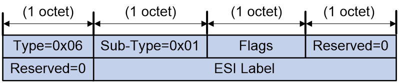
As shown in Figure 13, the ESI Label Extended Community includes the following fields:
· Flags: The last bit of this field is used to identify the redundancy backup mode for multi-homing. A value of 0 represents multi-active redundancy mode, and a value of 1 represents single-active redundancy mode.
· ESI Label: It is used for implementing split horizon in EVPN multi-homing networks. In different data encapsulation types, this field has different values.
¡ In MPLS encapsulation, it is the MPLS label.
¡ In VXLAN encapsulation, it has no significance.
¡ In SRv6 encapsulation, it is the SID argument.
ES-Import Route Target Extended Community
An extended community attribute carried in the Ethernet Segment Routes to advertise the route target of the ES.
Figure 14 ES-Import Route Target Extended Community packet format
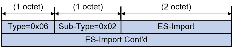
As shown in Figure 14, the ES-Import and ES-Import Cont'd fields in the ES-Import Route Target Extended Community attribute together represent the route target attribute automatically generated based on the ESI.
MAC Mobility Extended Community
When the host migrates, the number of migrations is identified by this attribute in the MAC/IP Advertisement Routes.
Figure 15 MAC Mobility Extended Community packet format
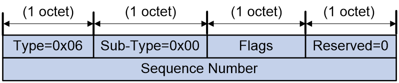
As shown in Figure 15, the MAC Mobility Extended Community includes the following fields:
· Flags: The last bit of this field is used to identify whether it is a static MAC. If the value is 1, it indicates that the MAC address is static and cannot be migrated.
· Reserved: Reserved field.
· Sequence Number: Number of MAC migrations.
Default Gateway Extended Community
In EVPN VXLAN distributed gateway networking, the attribute is carried in the MAC/IP Advertisement Route to indicate the gateway address.
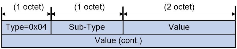
Figure 16 Default Gateway Extended Community packet format
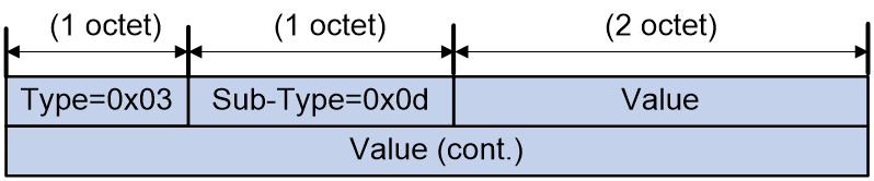
As shown in Figure 16, both the Value and Value (cont.) fields in the Default Gateway Extended Community are set to 0.
Encapsulation Type Extended Community
All BGP EVPN routes can carry this extended community attribute to identify the packet encapsulation type. By default, the packet encapsulation type is MPLS. Therefore, when MPLS encapsulation is used, BGP EVPN routes do not need to carry this attribute.
Figure 17 Encapsulation Type Extended Community packet format
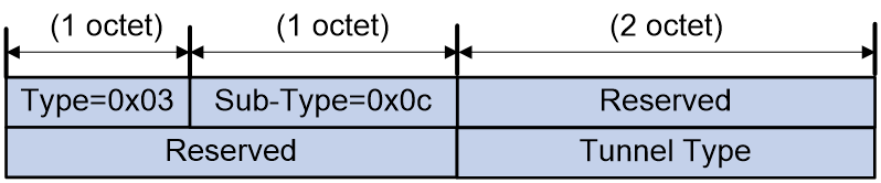
As shown in Figure 17, the Encapsulation Type Extended Community includes the following fields:
· Reserved: Reserved field.
· Tunnel Type: Encapsulation type:
¡ 8: VXLAN encapsulation.
¡ 9: NVGRE encapsulation.
¡ 10: MPLS encapsulation.
¡ 11: MPLS in GRE encapsulated.
¡ 12: VXLAN GPE encapsulation.
VPN Target Extended Community (Route Target)
All BGP EVPN routes carry this extended community attribute to control the advertisement and receipt of EVPN route information.
· When the local VTEP transmits the EVPN route to the remote VTEP through BGP Update messages, it carries the VPN Target attribute (also known as Export target attribute) in the Update messages.
· Upon receiving an Update message from another VTEP, the remote VTEP will match the VPN target attribute carried in the message with its locally configured VPN target attribute (known as import target attribute). The EVPN route in the message is received only when there is a match.
Figure 18 VPN Target Extended Community packet format
As shown in Figure 18, the Value and Value (cont.) fields in the VPN Target Extended Community together represent the route target.
A route target has the following formats:
· 16-bit AS number:32-bit user-defined number. For example, 101:3.
· 32-bit IP address:16-bit user-defined number. For example, 192.168.122.15:1.
· 32-bit AS number:16-bit user-defined number. The minimum AS number is 65536. For example: 65536:1.
EVPN VXLAN
EVPN VXLAN network model
Figure 19 EVPN VXLAN network model

As shown in Figure 19, the typical network model of EVPN VXLAN includes the following components:
· Terminal: It can be a PC, wireless client, or VM created on a server. Different terminals can belong to different VXLANs. Terminals within the same VXLAN are in the same logic Layer 2 network and can communicate with each other at Layer 2. Terminals in different VXLANs are isolated at Layer 2.
|
|
NOTE: This document, unless otherwise specified, uses VMs to explain the working mechanism of EVPN VXLAN. EVPN VXLAN operates the same way with other types of terminals as with VMs. |
· VTEP: An edge device in EVPN VXLAN. All relevant processing of EVPN VXLAN takes place on the VTEP. Based on the function of VTEP, it can be divided into two roles: L2 VTEP and GW.
¡ L2 VTEP: This is a device that only supports the function of layer 2 VXLAN forwarding, which means it can only perform layer 2 forwarding within the same VXLAN.
¡ GW: A device capable of performing Layer 3 forwarding across VXLAN or accessing external IP networks. Depending on the deployment method of the GW, the EVPN VXLAN network can be divided into centralized gateways and distributed gateways.
· VXLAN Tunnel: A point-to-point logic tunnel between two VTEPs. After a VTEP encapsulates a data frame with a VXLAN, UDP, and IP header, it forwards the encapsulated packet to the remote VTEP via the VXLAN tunnel. The remote VTEP then performs decapsulation.
· Core device: A device in the IP core network (such as the P device in Figure 19). Core devices do not participate in EVPN processing; they only need to perform layer-3 forwarding based on the outer destination IP address of the encapsulated packet.
· VXLAN Network/EVPN Instance: Customer networks may include user endpoints distributed across multiple sites in different geographic locations. Using VXLAN tunnels on the backbone network, these sites can be connected to provide users with a logical Layer 2 VPN. This Layer 2 VPN is called a VXLAN network, also known as an EVPN instance. The VXLAN network is identified by a VXLAN ID, also known as a VNI (VXLAN Network Identifier), which is 24 bits long. User endpoints in different VXLAN networks cannot communicate with each other at Layer 2.
· A Virtual Switch Instance (VSI) is a virtual switch instance on a VTEP that provides Layer 2 switching services for a single VXLAN. A VSI can be considered as a virtual switch on the VTEP that performs Layer 2 forwarding based on VXLAN. Each VSI corresponds to a single VXLAN.
· ES (Ethernet Segment): A link where user sites are connected to the VTEP, uniquely identified by ESI (Ethernet Segment Identifier). When a site accesses the EVPN VXLAN network through multiple links, these links form an ES to achieve primary and secondary backup OR load sharing.
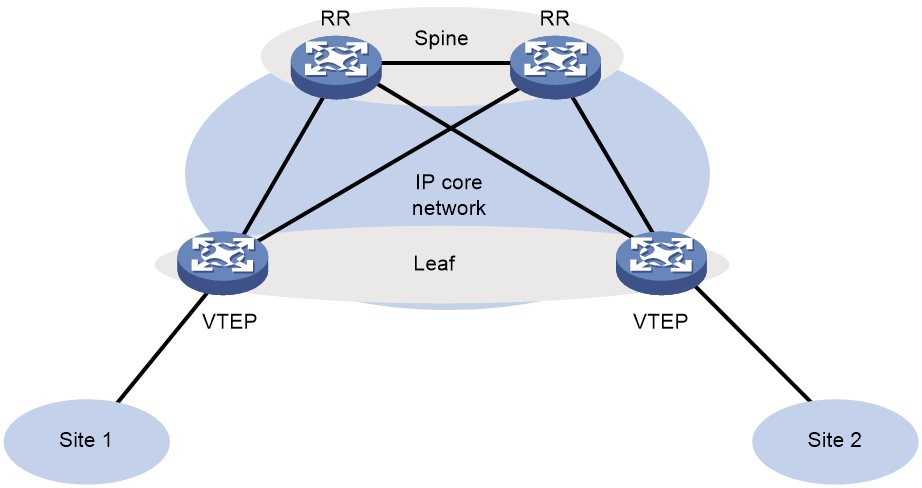
As shown in Figure 20, EVPN VXLAN typically adopts a layered structure with Spine (core) and Leaf (branch). Devices in the Leaf layer serve as VTEP, processing EVPN-related tasks, while Spine layer devices are core devices that forward messages based on the destination IP address. In an EVPN {VXLAN} network, when all devices belong to the same autonomous system (AS), the core devices can be configured as route reflector (RR) to reduce deployment complexity, avoiding the need to establish IBGP peers among all VTEPs. In general, within a centralized gateway network, VTEP is an L2 VTEP, and one RR also functions as a gateway; in a distributed gateway network, VTEP serves as GW, and RR only releases and receives EVPN routes as a reflector without the need for VXLAN encapsulation and decapsulation.
Figure 20 EVPN VXLAN Stratified Group Network Model
EVPN VXLAN control plane working mechanism
Establishment of VXLAN tunnels and BUM broadcast table
VXLAN uses "MAC in UDP" encapsulation, a technology to build Overlay network on the basis of the IP network. When transmitting packets in the IP network, VXLAN uses Ingress Replication, also known as head-end duplication, to forward BUM (Broadcast/Unknown unicast/Unknown Multicast) traffic. Head-end duplication refers to the process where the VXLAN forwarding entity (VSI) determines which VXLAN tunnels need to replicate BUM traffic to the remote PE device. This list of VXLAN tunnels is called the BUM Broadcast list.
The VXLAN tunnel and BUM broadcast table in EVPN VXLAN can be established in the following two ways:
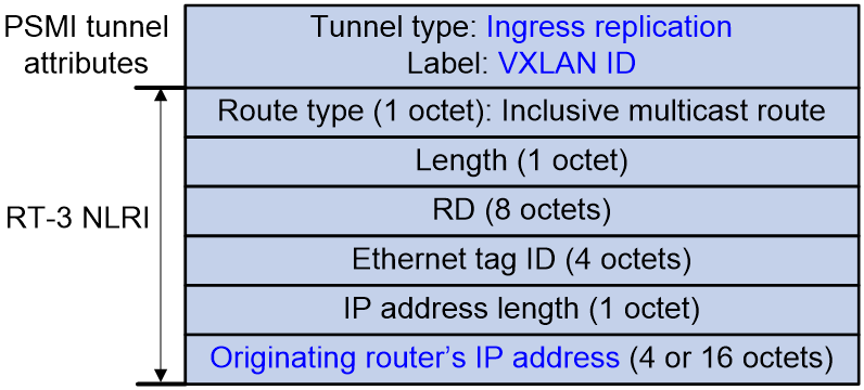
· During Layer 2 forwarding, EVPN VXLAN relies on RT-3 (Inclusive Multicast Ethernet Tag Route) for autodiscovery of VTEP sites, establishing VXLAN tunnels, and creating BUM broadcast tables.
The key information and route format of RT-3 routes are shown in Figure 21. Each VTEP advertises its associated VXLAN ID and its IP address through RT-3. This way, every VTEP device has complete network VXLAN information and the relationship between VXLAN and next hop. VTEP devices automatically establish VXLAN tunnels with next hops that have the same VXLAN and associate these tunnels with the VXLAN. As a result, for each VXLAN, all established and associated VXLAN tunnels form a BUM broadcast table.
Figure 21 RT-3 route message format
· During Layer 3 forwarding in distributed gateways, EVPN VXLAN relies on RT-2 OR RT-5 for autodiscovery of VTEP sites and establishing VXLAN tunnels.
When the distributed gateway receives either an RT-2 OR RT-5 route advertise (Annc) from a remote gateway with an Export target property that matches the Import target property of a local VPN instance, the local VTEP establishes a VXLAN tunnel with the remote VTEP. This VXLAN tunnel is associated with the Layer 3 VNI (L3VNI, a layer 3 VXLAN ID) that corresponds to the VPN instance. This tunnel is used for encapsulation when performing layer 3 forwarding. For a detailed description of the distributed gateway, see "2.3.3 Distributed Gateway Symmetric IRB Forwarding".
If the same Remote VTEP is discovered through the above two ways, only one tunnel should be established. This tunnel is associated with different VXLANs and used for both Layer 2 and Layer 3 forwarding. That is, at most one VXLAN tunnel will be established between two VTEPs.
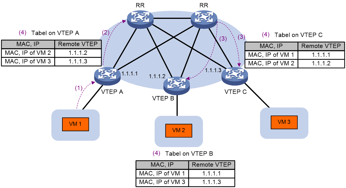
Advertisement and learning of MAC/IP advertisement routes
EVPN VXLAN learns MAC addresses and ARP/ND information on the control plane. MAC addresses and ARP/ND information of a site advertise through the EVPN's MAC/IP release route (i.e., RT-2, a class two route). Therefore, in an EVPN VXLAN network, there is no need to flood ARP/ND requests into the network.
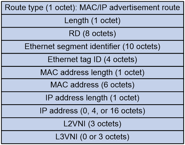
The format of the RT-2 route is shown in Figure 22.
Figure 22 The format of route RT-2
As shown in Figure 23, the advertisement and learning process for MAC address and ARP/ND information is as follows:
1. VTEP completes the learning of local MAC addresses and ARP/ND information on the data plane. The local MAC address is obtained by learning from the source MAC (SMAC) in Ethernet messages; ARP/ND information is obtained by learning from ARP, gratuitous ARP, ND and other messages.
2. After learning the local MAC address and ARP/ND information, VTEP releases this information to RR through BGP EVPN's RT-2 route on the control plane.
3. RR will synchronize the received RT-2 route with all BGP EVPN neighbors (remote VTEP).
4. Upon receiving the RT-2 route from the remote VTEP, the MAC address is added to the MAC address forwarding table, and the ARP/ND information is added to both the ARP/ND table and the routing table.
Figure 23 Process of MAC/IP route advertisement and learning
When releasing RT-2 route, VTEP can choose whether or not to carry IP. To suppress ARP request flooding in the network, it is usually necessary to carry IP to allow the remote VTEP to learn the host ARP under the local VTEP, enabling the remote VTEP to directly respond to the ARP request initiated by the remote host. If it's purely a second-layer network without third-layer forwarding, only the MAC address is carried in RT-2. Since the remote VTEP can get the MAC address from the ARP information in a three-layer forwarding environment, Comware can prohibit the advertisement of RT-2 routes that only contain a MAC address, in order to reduce the number of EVPN route advertisements.
In centralized gateway networking, the L2 VTEP needs to advertise the learned ARP to the gateway. The GW then adds this ARP entry, and generates a 32-bit host route. The next hop for the route is the destination address of the route itself.
In a distributed gateway network, each distributed gateway advertises the learned ARP to other gateways. On the remote GW, the IP address in RT-2 is delivered to the routing table of the VPN-instance to form a 32-bit host route. The next hop for this route is the GW device that advertises this route.
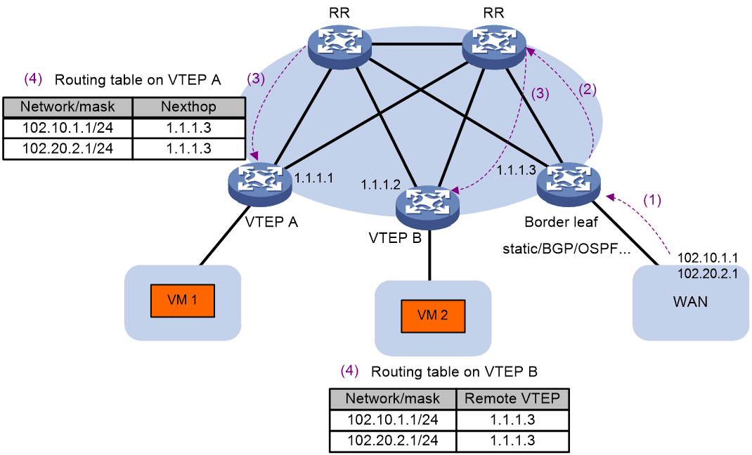
Advertisement and learning of external routes
The EVPN VXLAN network constructs a private network, which can also communicate with the external network by connecting to it. Normally in the Spine-Leaf schema of EVPN VXLAN, one or more devices dedicated to accessing the external network are deployed, referred to as Board leaf. The Board leaf runs a normal routing protocol between the common interface and the external network to learn routes; thereafter, on the Board leaf, these external routes can be introduced into EVPN VXLAN to form EVPN RT-5 (class 5) routes, which are then advertised to the EVPN VXLAN network, enabling other VTEPs to learn these external routes. The next hop of these routes all point to the Board leaf that advertised the route. When multiple Board leafs exist in the network, these Board leafs can all advertise this route, thereby forming equal cost routes, aiming to achieve load sharing.
The format of class 5 route is shown as in Figure 24.
As shown in Figure 25, the process of announcing and learning external routes is:
1. Configure a static route between Board leaf and the WAN network, or run Dynamic Routing Protocols such as BGP, OSPF, etc. Board leaf learns the route to the external network.
2. On the Board leaf, external routes are redistributed into EVPN, forming 5 classes of EVPN routes, and are then released to RR.
3. RR advertises class 5 route reflection from the Board leaf to other VTEPs.
4. Upon receiving class 5 routes, if the Export target properties of the route match the Import target properties of a local VPN-instance, the remote VTEP adds this route to the routing table of the VPN instance.
Figure 25 The advertisement and learning process of the external route
MAC address migration
MAC address migration refers to the migration of a host/VM from its access VTEP to another VTEP in the data center network. EVPN VXLAN ensures that the VTEP can promptly update the MAC/IP route after the host/VM migration by carrying the MAC Mobility extended community attribute in the BGP update message.
1. When VTEP releases a MAC/IP route for the first time, the BGP update message does not carry the MAC Mobility extended community attribute.
2. After the migration of host/VM, the newly migrated VTEP detects the online status of the host/VM, re-advertises the MAC/IP route, and carries a MAC Mobility extended community attribute in the route. This extended community package includes a sequence number. Each time a migration occurs, the migration sequence number will increase.
3. When the remote VTEP receives a MAC/IP route with a sequence number larger than its own local save, it updates its own MAC/IP route message and the next hop points towards the VTEP that advertised the route after migration.
4. Upon receiving this routing update, the original VTEP undoes the route previously advertised.
ARP flooding suppression
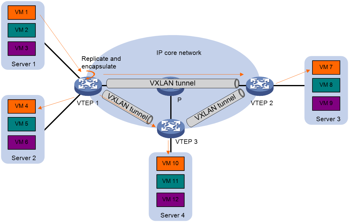
To prevent broadcast ARP request packets from occupying the core network bandwidth, VTEP establishes local ARP cache table entries based on received ARP requests and responses, as well as RT-2 routes from BGP EVPN. Subsequently, when VTEP receives an ARP request from a VM within the same site asking for another VM's MAC address, it prioritizes proxy responses based on locally stored ARP entries. If there is no corresponding entry, the ARP request is flooded to the core network. The ARP flood suppression function can greatly reduce the number of ARP floods.
Figure 26 ARP flooding suppression
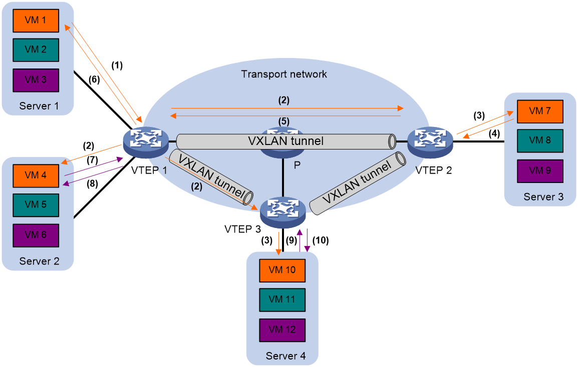
As shown in Figure 26, the processing procedure for ARP flooding suppression is as follows:
1. The VM VM 1 transmits an ARP request to obtain the MAC address of VM 7.
2. Based on the ARP request received, VTEP 1 sets up an ARP flooding suppression entry for VM1 and floods this ARP request within VXLAN (taking unicast route flooding example as per <field name="Ref" value="Figure 26"/>). VTEP 1 also syncs this entry with VTEP 2 and VTEP 3 through BGP EVPN.
3. The remote VTEP (VTEP 2 and VTEP 3) decapsulate the VXLAN packet to obtain the original ARP request packet, then flood this ARP request within the specified VXLAN at the local site.
4. After receiving the ARP request, VM 7 responds with an ARP reply message.
5. After receiving the ARP response, VTEP 2 establishes an ARP flooding suppression entry for VM 7, and transmits the ARP response to VTEP 1 via the VXLAN tunnel. Then, VTEP 2 synchronizes this entry with VTEP 1 and VTEP 3 using BGP EVPN.
6. VTEP 1 decapsulates the VXLAN packet to obtain the original ARP response, and then transmits this ARP response packet to VM 1.
7. After establishing an ARP flooding suppression entry on VTEP 1, VM VM 4 transmits an ARP request to obtain VM 1's MAC address.
8. After receiving an ARP request, VTEP 1 establishes an ARP flooding suppression entry for VM 4, searches for the local ARP flooding suppression entry, responds to the ARP request message based on the existing entries, and does not flood the ARP request.
9. Virtual machine VM 10 transmits an ARP request to obtain the MAC address of VM 1.
10. After receiving the ARP request, VTEP 3 establishes an ARP flooding suppression entry for VM 10, and then searches for the ARP flooding suppression entry. Based on the existing entry, (which was synchronized via VTEP 1 through BGP EVPN), VTEP 3 responds with an ARP reply message, and will not flood the ARP request.
EVPN VXLAN data plane working mechanism
Layer 2 traffic forwarding
Known unicast traffic forwarding
EVPN VXLAN learns the MAC address entry via the control plane. Once the VTEP receives a Layer 2 data frame, it determines its associated VSI, and looks up the MAC address table of that VSI using the destination MAC address, then forwards the data frame via the entry's egress interface. If the egress interface is a local interface, the VTEP directly forwards the data frame through that interface. If the egress interface is a tunnel interface, the VTEP adds a VXLAN encapsulation to the data frame based on the tunnel interface, and forwards it to the remote VTEP through the VXLAN tunnel.
BUM traffic forwarding
In addition to unicast traffic forwarding, the EVPN VXLAN network also needs to forward broadcast, unknown multicast, and unknown unicast traffic, collectively known as BUM traffic. EVPN VXLAN uses head-end replication to forward BUM traffic.
Upon receiving multicast, broadcast, and unknown unicast data frames from local VMs, the VTEP determines the VXLAN to which the data frame belongs. It then forwards the data frame through all local interfaces and VXLAN tunnels within that VXLAN, excluding the receiving interface. When transmitting the data frame through a VXLAN tunnel, the VTEP encapsulates it with a VXLAN header, UDP header, and IP header. The flooding traffic is encapsulated in multiple unicast packets, which are sent to all remote VTEPs within the VXLAN. The head-end replication list for VXLAN (i.e., the BUM broadcast list) is created and maintained automatically through EVPN autodiscovery, eliminating the need for manual intervention.
Figure 27 BUM Traffic Duplication and Forwarding
Centralized gateway forwarding
In centralized EVPN gateway networking, the L2 VTEP advertises the locally learned ARP to the gateway using EVPN route. The GW creates an ARP entry with the MAC address of the VM. The GW also generates a 32-bit host route based on the ARP, with the next hop being the destination address itself (i.e., the IP address of the VM).
The method of centralized gateway forwarding traffic is as follows:
· For traffic from the external network accessing the VM in the EVPN VXLAN network, the GW receives the packets and performs layer 3 table forwarding. Based on the 32-bit host route, the next hop fetched is the VM’s IP address. The GW then searches for the ARP entry corresponding to the VM's IP address, and encapsulates the inner target MAC address in the packet with the VM's MAC address, along with the addition of a VXLAN encapsulation before transmitting it to L2 VTEP. After L2 VTEP performs decapsulation, it carries out layer 2 forwarding according to the target MAC address, and transmits the packets to the VM.
· In the EVPN VXLAN network, when a VM accesses the external network, the destination MAC of the message transmitted by the VM to VTEP is the gateway MAC of the GW. VTEP looks up the MAC address entry, adds a VXLAN encapsulation, and then sends the message to the GW. After decapsulation by the GW, the packet is forwarded based on the destination IP address of the internal message. At this point, the GW plays the role of an IP gateway.
· For traffic between different VMs within an EVPN VXLAN network, if the VMs belong to the same VXLAN, Layer 2 forwarding can be performed by looking up the MAC address table on the VTEP. If the VMs belong to different VXLANs, the destination MAC of the message sent by the VM to the VTEP is the gateway MAC of the GW, which needs to go through the GW for Layer 3 forwarding to forward the message to the destination VXLAN. At this time, the GW acts as the VXLAN gateway role.
Distributed gateway symmetrical IRB
In the symmetrical IRB forwarding method of distributed gateway, the processing method is the same on both the entrance gateway and the exit gateway. For Layer 2 traffic, both the entrance and exit gateways only conduct Layer 2 forwarding. Similarly, for the Layer 3 traffic, both gateways only conduct Layer 3 forwarding.
Basic concepts
Symmetric IRB introduces the following concepts:
· L3 VXLAN ID—Also called L3 VNI. An L3 VXLAN ID identifies the traffic of a routing domain where devices have Layer 3 reachability. An L3 VXLAN ID is associated with one VPN instance. Distributed EVPN gateways use VPN instances to isolate traffic of different services on VXLAN tunnel interfaces.
· Router MAC address—Each distributed EVPN gateway has a unique router MAC address used for inter-gateway forwarding. The MAC addresses in the inner Ethernet header of VXLAN packets are router MAC addresses of distributed EVPN gateways.
VSI interfaces
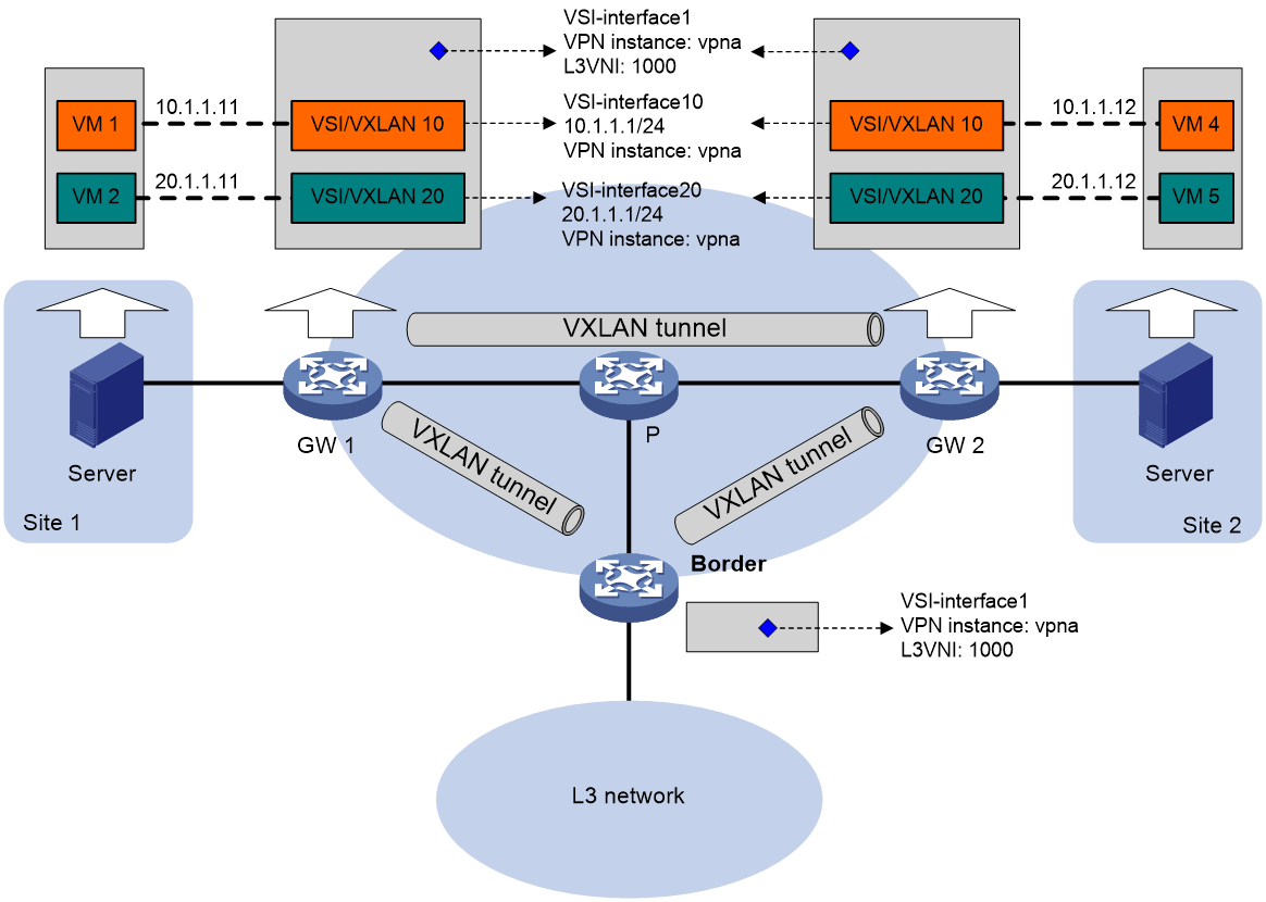
As shown in Figure 28, each distributed EVPN gateway has the following types of VSI interfaces:
· VSI interface as a gateway interface of a VXLAN—The VSI interface acts as the gateway interface for VMs in a VXLAN. The VSI interface is associated with a VSI and a VPN instance. On different distributed EVPN gateways, the VSI interface of a VXLAN uses the same IP address to provide services.
· VSI interface associated with an L3 VXLAN ID—The VSI interface is associated with a VPN instance and assigned an L3 VXLAN ID. VSI interfaces associated with the same VPN instance share an L3 VXLAN ID.
A border gateway only has VSI interfaces that are associated with an L3 VXLAN ID.
Figure 28 Distributed EVPN gateway deployment
Traffic forwarding
A distributed EVPN gateway can work in one of the following modes:
· Switching and routing mode—Forwards Layer 2 traffic based on the MAC address table and forwards Layer 3 traffic based on the FIB table. In this mode, you need to enable ARP or ND flood suppression on the distributed EVPN gateway to reduce flooding.
· Routing mode— Forwards both Layer 2 and Layer 3 traffic based on the FIB table. In this mode, you need to enable local proxy ARP on the distributed EVPN gateway.
Figure 29 shows the intra-site Layer 3 forwarding process.
1. The source VM sends an ARP request to obtain the MAC address of the destination VM.
2. The gateway replies to the source VM with the MAC address of the VSI interface associated with the source VM's VSI.
3. The source VM sends a Layer 3 packet to the gateway.
4. The gateway looks up the FIB table of the VPN instance associated with the source VM's VSI and finds the matching outgoing site-facing interface.
5. The gateway processes the Ethernet header of the Layer 3 packet as follows:
¡ Replaces the destination MAC address with the destination VM's MAC address.
¡ Replaces the source MAC address with the VSI interface's MAC address.
6. The gateway forwards the Layer 3 packet to the destination VM.
Figure 29 Intra-site Layer 3 forwarding
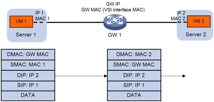
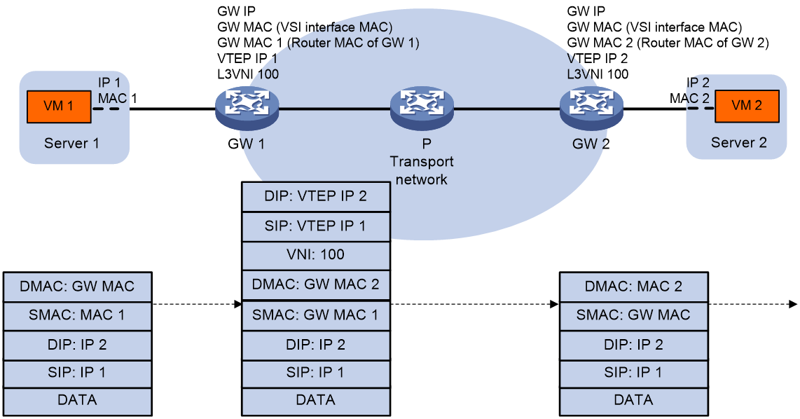
Figure 30 shows the inter-site Layer 3 forwarding process.
7. The source VM sends an ARP request to obtain the MAC address of the destination VM.
8. The gateway replies to the source VM with the MAC address of the VSI interface associated with the source VM's VSI.
9. The source VM sends a Layer 3 packet to the gateway.
10. The gateway looks up the FIB table of the VPN instance associated with the source VM's VSI and finds the matching outgoing VSI interface.
11. The gateway processes the Ethernet header of the Layer 3 packet as follows:
¡ Replaces the destination MAC address with the destination gateway's router MAC address.
¡ Replaces the source MAC address with its own router MAC address.
12. The gateway adds VXLAN encapsulation to the Layer 3 packet and forwards the packet to the destination gateway. The encapsulated VXLAN ID is the L3 VXLAN ID of the corresponding VPN instance.
13. The destination gateway identifies the VPN instance of the packet based on the L3 VXLAN ID and removes the VXLAN encapsulation. Then the gateway forwards the packet based on the matching ARP entry.
Figure 30 Inter-site Layer 3 forwarding
In a distributed gateway topology, each distributed gateway only needs to be configured with the VXLAN ID of the attached hosts/VMs. Moreover, the distributed gateway does not need to maintain the ARP information of all hosts/VMs within the tenant; it only needs to maintain the ARP information of a few remote distributed gateways.
Distributed gateway asymmetrical IRB
In the distributed gateway asymmetric IRB forwarding method, the processing methods on the entrance gateway and exit gateway are different. The entrance gateway needs to perform both Layer 2 and Layer 3 forwarding, while the exit gateway only performs Layer 2 forwarding.
VSI interfaces
Asymmetric IRB uses the same distributed EVPN gateway deployment as symmetric IRB.
Each distributed EVPN gateway has the following types of VSI interfaces:
· VSI interface as a gateway interface of a VXLAN—The VSI interface is associated with a VSI and a VPN instance. On different distributed EVPN gateways, the VSI interface of a VXLAN must use different IP addresses to provide services.
· VSI interface associated with an L3 VXLAN ID—The VSI interface acts as the gateway for VMs in a VXLAN to communicate with the external network through the border gateway. The VSI interface is associated with a VPN instance and assigned an L3 VXLAN ID. VSI interfaces associated with the same VPN instance share an L3 VXLAN ID.
A border gateway only has VSI interfaces that are associated with an L3 VXLAN ID.
Layer 3 forwarding
Asymmetric IRB supports only Layer 3 forwarding in the same VXLAN on distributed EVPN gateways.
After a distributed EVPN gateway learns ARP information about local VMs, it advertises the information to other distributed EVPN gateways through MAC/IP advertisement routes. Other distributed EVPN gateways generate FIB entries based on the advertised ARP information.
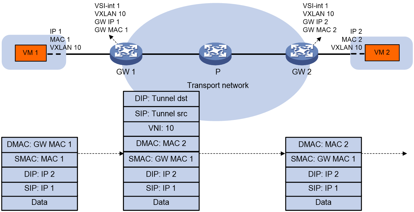
As shown in Figure 31, VM 1 and VM 2 belong to VXLAN 10 and they can reach each other at Layer 3 through the distributed EVPN gateways. The distributed EVPN gateways use the following process to perform Layer 3 forwarding in asymmetric IRB mode when VM 1 sends a packet to VM 2:
1. After GW 1 receives the packet from VM 1, it finds that the destination MAC address is itself. Then, GW 1 removes the Layer 2 frame header and looks up the FIB table for the destination IP address.
2. GW 1 matches the packet to the FIB entry generated based on the ARP information of VM 2.
3. GW 1 encapsulates the packet source and destination MAC addresses as the MAC addresses of GW 1 and VM 2, respectively. Then, GW 1 adds VXLAN encapsulation to the packet and forwards the packet to GW 2 through a VXLAN tunnel.
4. GW 2 removes the VXLAN encapsulation from the packet, and performs Layer 2 forwarding in VXLAN 10 by looking up the MAC address table for the destination MAC address.
5. GW 2 forwards the packet to VM 2 based on the MAC address table lookup result.
Figure 31 Layer 3 forwarding in the same VXLAN (asymmetric IRB)
EVPN VXLAN multihoming
About EVPN VXLAN multihoming
As shown in Figure 32, EVPN supports deploying multiple VTEPs at a site for redundancy and high availability. On the redundant VTEPs, Ethernet links connected to the site form an Ethernet segment (ES) that is uniquely identified by an Ethernet segment identifier (ESI).
Figure 32 EVPN VXLAN multihoming
DF election
To prevent redundant VTEPs from sending duplicate flood traffic to a multihomed site, a designated forwarder (DF) is elected from the VTEPs to forward flood traffic to the site. VTEPs that fail the election are assigned the backup designated forwarder (BDF) role. BDFs do not forward flood traffic to the site.
Redundant VTEPs at a site send Ethernet segment routes to one another to advertise ES and VTEP IP mappings. A VTEP accepts the Ethernet segment routes only when it is configured with an ESI. Then, the VTEPs select a DF for each AC based on the ES and VTEP IP mappings. DF election can be performed by using a VLAN tag-based algorithm or preference-based algorithm.

VLAN tag-based DF election
VTEPs select a DF for each AC based on the VLAN tag and VTEP IP address as follows:
1. Arrange source IP addresses in Ethernet segment routes with the same ESI in ascending order and assign a sequence number to each IP address, starting from 0.
2. Divide the lowest VLAN ID permitted on an AC by the number of the redundant VTEPs, and match the reminder to the sequence numbers of IP addresses.
3. Assign the DF role to the VTEP that uses the IP address with the matching sequence number.
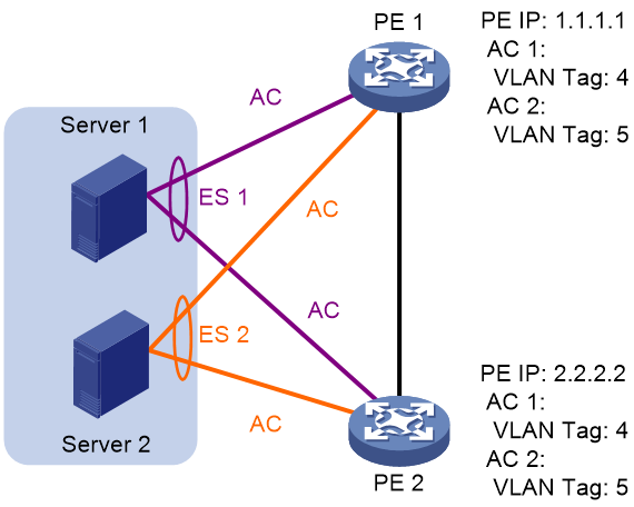
The following uses AC 1 in Figure 34 as an example to explain the DF election procedure:
4. VTEP 1 and VTEP 2 send Ethernet segment routes to each other.
5. The VTEPs assign sequence numbers 0 and 1 to IP addresses 1.1.1.1 and 2.2.2.2 in the Ethernet segment routes, respectively.
6. The VTEPs divide 4 (the lowest VLAN ID permitted by AC 1) by 2 (the number of redundant VTEPs), and match the reminder 0 to the sequence numbers of the IP addresses.
7. The DF role is assigned to VTEP 1 at 1.1.1.1.
Figure 34 VLAN tag-based DF election
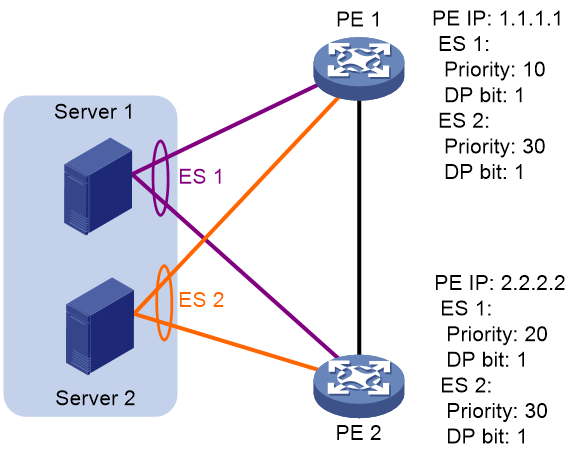
Preference-based DF election
VTEPs select a DF for each ES based on the DF election preference, the Don't Preempt Me (DP) bit in Ethernet segment routes, and VTEP IP address. The DP bit can be set to one of the following values:
· 1—DF preemption is disabled. A DF retains its role when a new DF is elected.
· 0—DF preemption is enabled.
Preference-based DF election uses the following rules to select a DF for an ES:
· The VTEP with higher preference becomes the DF.
· If two VTEPs have the same preference, the VTEP with the DP bit set to 1 becomes the DF. If both of the VTEPs have the DP bit set to 1, the VTEP with a lower IP address becomes the DF.
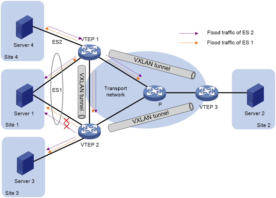
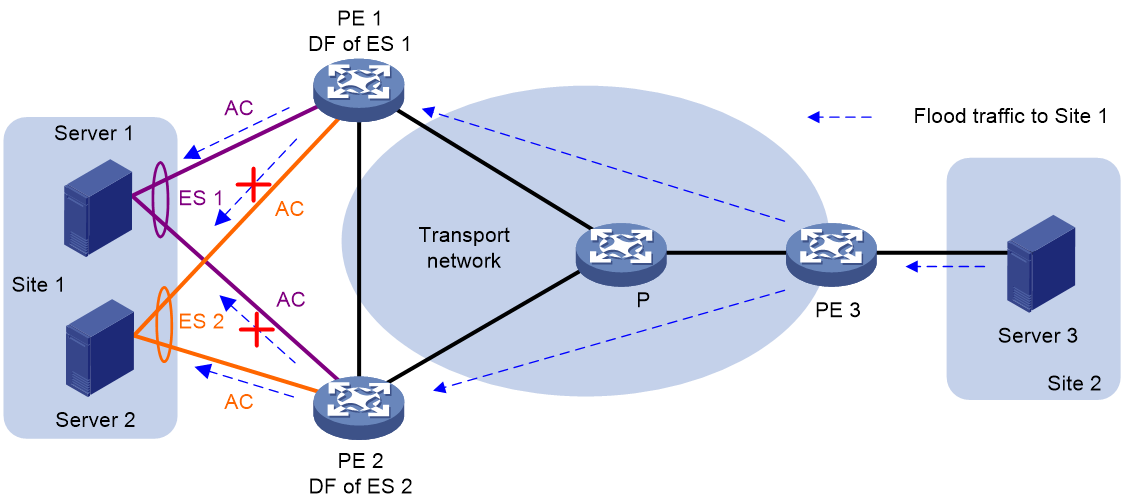
As shown in Figure 35, VTEP 2 is the DF for ES 1, and VTEP 1 is the DF for ES 2.
Figure 35 Preference-based DF election
Protocol packet exchange
Split horizon
In a multihomed site, a VTEP forwards multicast, broadcast, and unknown unicast frames received from ACs out of all site-facing interfaces and VXLAN tunnels in the corresponding VXLAN, except for the incoming interface. As a result, the other VTEPs at the site receive these flood frames and forward them to site-facing interfaces, which causes duplicate floods and loops. EVPN introduces split horizon to resolve this issue. Split horizon disables a VTEP to forward flood traffic received from another local VTEP to site-facing interfaces if an ES on that local VTEP has the same ESI as these interfaces. As shown in Figure 36, both VTEP 1 and VTEP 2 have ES 1. When receiving flood traffic from VTEP 1, VTEP 2 does not forward the traffic to interfaces with ESI 1.
Alias
Figure 37 Alias network diagram
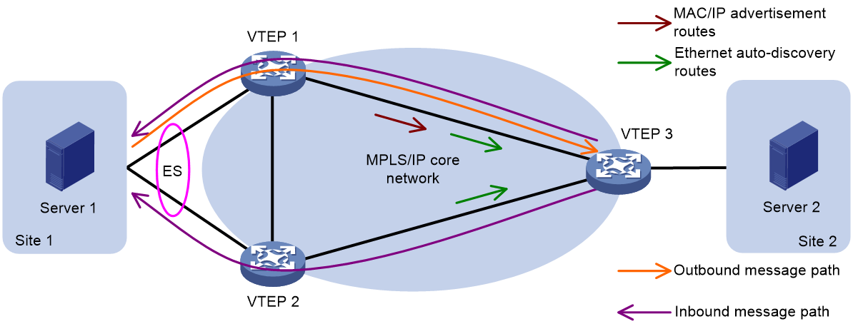
As shown in Figure 37, in multi-active redundancy mode, only one VTEP in the redundancy group might learn some business-related MAC addresses. This could cause the remote PE to only receive the MAC/IP release route of these MAC addresses from this VTEP. Therefore, the remote VTEP cannot share the traffic load accessing these MAC addresses to other VTEPs in the redundancy group.
To address this issue, EVPN multi-homing introduces the alias mechanism. That is, when only one VTEP in the redundancy backup group advertises the reachability of the server-side MAC address to the remote VTEP by passing MAC/IP release route, the remote VTEP can perceive the reachability of other VTEPs and MAC addresses within the redundancy backup group based on the Ethernet autodiscovery route (carrying VTEP, ESI, and other information) transmitted by the VTEP in the group. This creates corresponding MAC address entries, thus enabling load sharing.
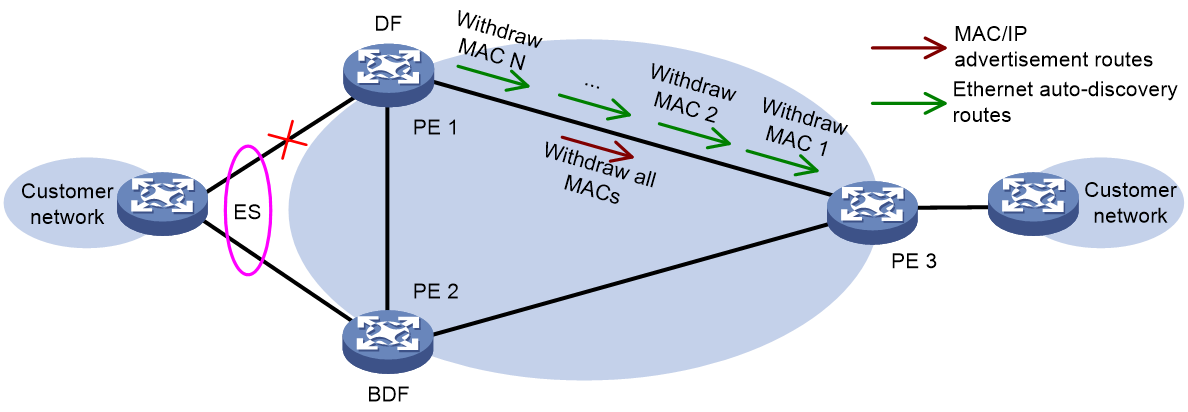
MAC address fast convergence
Figure 38 MAC address fast convergence
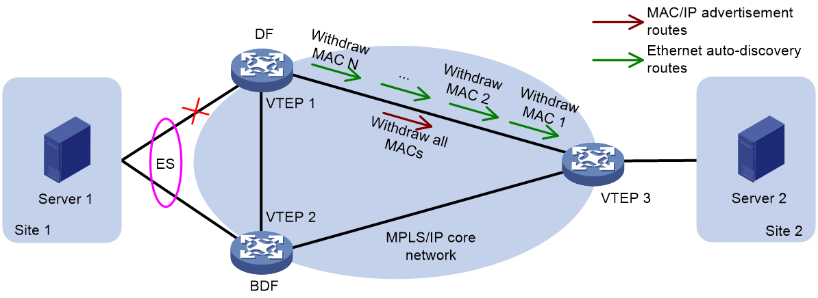
As shown in Figure 38, in the EVPN network, MAC address reachability is achieved by releasing MAC/IP route advertisements between VTEPs. Therefore, when a link fault occurs between CE 1 and VTEP 1, VTEP 1 needs to undo the MAC/IP route release one by one, which in a large-scale network may lead to a slower convergence speed of MAC addresses.
The multi-homing network of EVPN provides a fast convergence mechanism, enabling the VTEP to achieve unreachability for all MAC addresses within a specific ES, by undoing an Ethernet autodiscovery route. It advertises the unreachability to the remote VTEP, prompting a bulk delete of MAC address entries, thereby reducing the convergence time.
Support of EVPN VXLAN for multicast
Introduction
To avoid IGMP multicast messages from consuming the core network bandwidth, VTEP will establish or delete multicast forwarding table entries based on the received reports and leave messages. The multicast group information is advertised to other VTEPs through SMET (Selective Multicast Ethernet Tag Route). When a remote VTEP receives the SMET route, it establishes a multicast forwarding table entry locally. When VTEP receives a report message of the same IGMP version joining the same multicast group again, it will no longer send the SMET route. EVPN VXLAN's support for multicasting can greatly reduce the number of IGMP message floods.
To support multicast, MP-BGP has added three classes of EVPN routes in the EVPN address family, namely SMET, IGMP-JS, and IGMP-LS. For detailed introductions, see "BGP EVPN route".
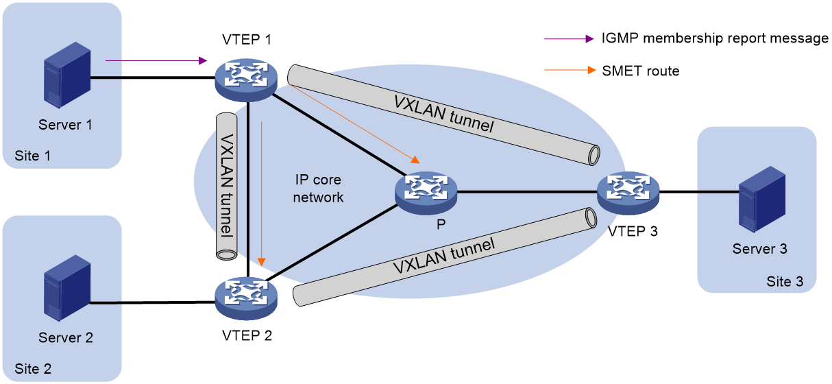
Single-homed site multicast
As shown in Figure 39, in single-home site networking, Server 1 transmits (Tx) a membership report message to VTEP 1. VTEP 1 generates the corresponding multicast entry and advertises (Annc) the multicast information to VTEP 2 and VTEP 3 by sending (Tx) the SMET route. Upon receiving the SMET route, VTEP 2 and VTEP 3 form a multicast entry with the next hop as VTEP 1.
Figure 39 Single-homed site multicast
Multi-homed site multicast
In a multi-home site mesh network, join and leave multicast group messages transmitted from the site side will be received by different VTEPs. To manage the multicast entry of the site among multi-home sites, the VTEPs that receive the join and leave multicast group messages will transmit IGMP-JS and IGMP-LS routes to inform other members, ensuring the synchronization of multicast information among VTEPs with the same ESI member.
Figure 40 Multi-homed site multicast
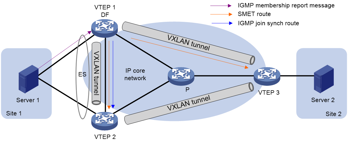
As shown in Figure 40, the multicast processing procedure for multi-affiliation sites is as follows:
· When the device receiving the report message is DF (VTEP 1), DF advertises SMET route to VTEP 2 and VTEP 3, and advertises IGMP-JS route to VTEP 2. When multicast receivers leave the multicast group:
¡ If the device receiving the departure message is the DF, then the DF will advertise the IGMP-LS route and undo the IGMP-JS route and SMET route.
¡ If the device that receives the leave message is BDF (VTEP 2), then BDF advertises the IGMP-LS route to other members of the same redundancy backup. After DF receives the synchronous IGMP-LS route from BDF, it undoes the IGMP-JS route and SMET route.
· When the device receiving the report message is BDF, the BDF advertises the IGMP-JS route to other members in the same redundancy backup. After DF receives the IGMP-JS route, it generates SMET route synchronization to VTEP 2 and VTEP 3. When the multicast receiver leaves the multicast group:
¡ If the device that receives the leave message is DF, then DF advertises the IGMP-LS route to other members in the same redundancy backup. BDF undoes the IGMP-JS route after receiving IGMP-LS route. After DF receives the undo IGMP-JS route, it cancels the SMET route generated by IGMP-JS route.
¡ If the device receiving the departure message is BDF, then BDF will advertise (Annc) the IGMP-LS route and undo the IGMP-JS route. Upon receiving the undoing of the IGMP-JS route, DF will retract the SMET route generated by this IGMP-JS route.
Typical networking scenarios
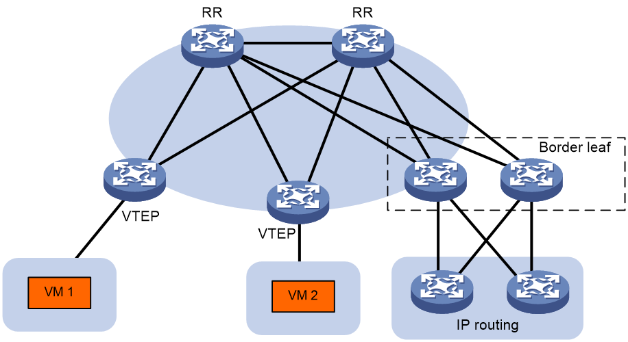
EVPN distributed gateway
In the EVPN distributed gateway networking, the demand for gateway device forwarding capability is not as high as that of the centralized gateway, and the core device only needs to support ordinary IP forwarding. Therefore, the EVPN distributed gateway application is widely used.
The typical network structure of the EVPN distributed gateway is shown in Figure 41. VTEP is the EVPN distributed gateway device; The border leaf is the border gateway device connected to the wide area network (WAN), with two border leaf devices deployed for backup purposes; The RR is responsible for reflecting the BGP route between switches.
Figure 41 EVPN distributed gateway network diagram
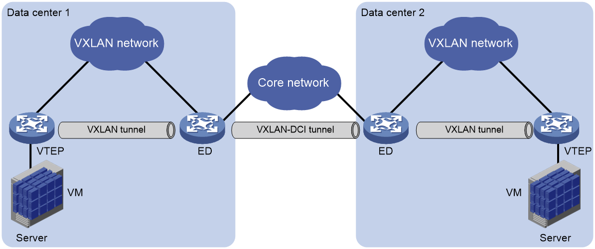
EVPN data center interconnection
The EVPN data center interconnect technology establishes a VXLAN-DCI (VXLAN Data Center Interconnect) tunnel between data centers to facilitate communication among VMs across different data centers.
As shown in Figure 42, the edge devices in the data center are ED (Edge Device). An VXLAN-DCI tunnel is established between the EDs, which uses the VXLAN encapsulation format. The ED establishes a VXLAN tunnel with VTEP inside the data center. After receiving a data packet from the VXLAN tunnel or VXLAN-DCI tunnel, the ED removes the VXLAN encapsulation, re-encapsulates the packet according to the destination IP address, and forwards it to the VXLAN-DCI tunnel or VXLAN tunnel, thereby realizing intercommunication between data centers.
Figure 42 Typical Networking Diagram of VXLAN Data Center Interconnection
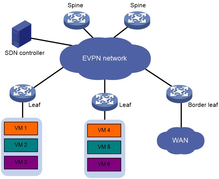
Configuring EVPN on SDN controller
SDN (Software Defined Network) is a new type of network schema that separates the control plane from the forwarding plane and is centrally controlled and managed by the SDN controller (CTL). As shown in Figure 43, EVPN can be used in conjunction with the SDN controller. All devices in the EVPN network are centrally managed by the SDN controller through standard protocols, reducing the complexity of traditional device management. Also, when user services expand, through centralized management (Mgmt), users can conveniently and quickly deploy network devices, facilitating network expansion and management.
Figure 43 EVPN and SDN controller (CTL) cooperate for network group configuration
EVPN VPLS
EVPN VPLS network model
Figure 44 EVPN VPLS network model

As shown in Figure 44, an EVPN VPLS network contains the following devices:
· Customer edge (CE)—Customer device directly connected to the service provider network.
· Provider edge (PE)—Service provider device connected to CEs. PEs provide access to the EVPN VPLS network and forward traffic between customer network sites by using public tunnels. A PE uses ACs, PWs, tunnels, and VSIs to provide EVPN VPLS services.
· Attachment circuit (AC)—A physical or virtual link between a CE and a PE.
· Pseudowire (PW)—A pair of unidirectional virtual connections in opposite directions between two PEs.
· Public tunnel—A connection that carries one or more PWs across the MPLS or IP backbone. A public tunnel can be an LSP, GRE, or MPLS TE tunnel.
· Virtual Switch Instance (VSI)—A virtual switch instance provides Layer 2 switching services for a VPLS instance (EVPN instance) on a PE. A VSI acts as a virtual switch that has all the functions of a conventional Ethernet switch, including source MAC address learning, MAC address aging, and flooding. VPLS uses VSIs to forward Layer 2 data packets in EVPN instances.
EVPN VPLS control plane working mechanism
PW establishment
In an EVPN VPLS network, PEs discover neighbors and establish PWs by using the following procedure:
1. The PEs assign two PW labels to each VSI for forwarding known unicast, broadcast, unknown unicast, and unknown multicast (BUM) packets.
2. Each PE advertises the PW labels to remote PEs as follows:
¡ Advertises the PW labels used for forwarding known unicast packets through MAC/IP prefix advertisement routes or Ethernet auto-discovery routes.
¡ Advertises the PW labels used for forwarding BUM traffic through IMET routes.
Those routes carry route targets.
3. Each PE matches the route targets in a received MAC/IP prefix advertisement route, Ethernet auto-discovery route, or IMET route with the import targets of the EVPN instance. If the route targets match the import targets, the PE establishes a unidirectional virtual connection based on the PE address and PW label information carried in the route.
4. PW establishment is finished when two virtual connections in opposite directions are established between two PEs.
MAC address learning, aging, and withdrawal
MAC address learning
A PE uses the MAC address table of a VSI to forward Layer 2 unicast traffic for that VSI.
A PE learns source MAC addresses in the following ways:
¡ Local MAC address learning—When the PE receives a frame from a local CE, it first identifies the VSI of the frame. Then, the PE adds the source MAC address of the frame (the MAC address of the local CE) to the MAC address table of the VSI. The output interface of the MAC address entry is the AC that receives the frame.
¡ Remote MAC address learning—A PE advertises the MAC addresses of local CEs to remote PEs through BGP EVPN MAC/IP advertisement routes. When a remote PE receives the routes, it adds the received MAC addresses to the MAC address table of the corresponding VSI. The output interface is the PW.
MAC address aging
· Local MAC address aging—The MAC address table uses an aging timer for each dynamic MAC address entry. If no packet is received from a MAC address before the aging timer expires, VPLS deletes the MAC address.
· Remote MAC address aging—Remote MAC addresses advertised through MAC/IP advertisement routes are not removed from the MAC address table until routes to withdraw the MAC addresses are received.
MAC address withdrawal
When an AC goes down, the PE deletes MAC addresses on the AC. Then it sends an LDP address withdrawal message to notify all other PEs in the EVPN instance to delete those MAC addresses.
MAC address migration
MAC address migration refers to the transition of a host/VM from its access PE to another PE. Through carrying the MAC Mobility extended community attribute in the BGP update message, EVPN VPLS ensures that after the host/VM migration, the VTEP can update the MAC/IP route timely.
1. When PE releases a specific MAC/IP route for the first time, the BGP update message does not carry the MAC Mobility extended community attribute.
2. After the host/VM migration, the newly migrated PE detects the host/VM going online and re-advertises the MAC/IP route, carrying the MAC Mobility extended community attribute in the route. This extended community contains a sequence number. Each time a migration occurs, the migration sequence number will increase.
3. When the remote PE receives a MAC/IP route with a sequence number larger than the one saved locally, it updates its MAC/IP route message, with the next hop pointing to the PE that advertises this route after migration.
4. After receiving this routing update, the original VTEP undoes the previously advertised route.
ARP flood suppression
To avoid ARP request messages broadcasted occupying the core network bandwidth, PE will establish local ARP flood suppression entry based on the received ARP requests, ARP response messages and BGP EVPN routes. When PE receives another ARP request from a VM at the local site requesting the MAC address of another VM, it prioritizes responding based on ARP flood suppression entry. If there's no corresponding entry, it will pass the ARP request and flood it to other sites through PW. The ARP flood suppression function can significantly reduce the number of ARP flood instances.
Figure 45 ARP flooding suppression
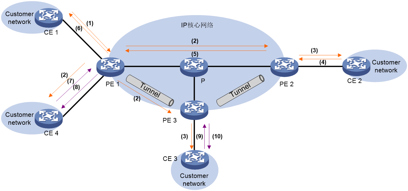
As shown in Figure 45, ARP flood suppression uses the following workflow:
1. The VM CE 1 transmits an ARP request to obtain the MAC address of CE 2.
2. PE 1 establishes an ARP flooding suppression entry for CE 1 based on the received ARP request and floods the request to the local CE and remote PEs (PE 2 and PE 3) within the VSI (as shown in Figure 45, using unicast route flooding as an example). PE 1 also synchronizes this entry with PE 2 and PE 3 through BGP EVPN.
3. The remote PE decapsulates the packet to obtain the original ARP request packet, and then floods this ARP request to the local CE within the VSI.
4. After receiving the ARP request, CE 2 responds with an ARP reply message.
5. After receiving the ARP response, PE 2 establishes an ARP flooding suppression entry for CE 2 and transmits the ARP response to PE 1 via PW. PE 2 then synchronizes this entry with PE 1 and PE 3 through BGP EVPN.
6. PE 1 decapsulates the packet to obtain the original ARP response, and then transmits the ARP response message to CE 1.
7. After establishing the ARP flooding suppression entry on PE 1, CE 4 transmits an ARP request to acquire the MAC address of CE 1.
8. Upon receiving the ARP request, PE 1 sets up the ARP flooding suppression entry for CE 4 and searches for the local ARP flooding suppression entry. Based on the existing entries, PE 1 will reply with an ARP response packet without flooding the ARP request.
9. CE 3 transmits an ARP request to obtain the MAC address of CE 1.
10. After PE 3 receives the ARP request, it establishes an ARP flooding suppression entry for CE 3, and searches the ARP flooding suppression entries. According to the existing entry (synchronized by PE 1 through BGP EVPN), it replies with an ARP response message, not causing flooding to the ARP request.
EVPN VPLS data plane working mechanism
Local site access mode
The local site can connect to the EVPN VPLS network in the following ways:
· Port mode
The local site accesses the EVPN VPLS network through a Layer 3 Ethernet interface. All messages received from this interface belong to the VSI associated with the Layer 3 Ethernet interface.
In this access mode, the Layer 3 Ethernet interface acts as an AC.
· VLAN mode
The local site accesses the EVPN VPLS network via a Layer 3 Ethernet subinterface. All VLAN messages received from the Layer 3 Ethernet interface, which are terminated by this subinterface, belong to the VSI associated with the Layer 3 Ethernet subinterface.
In this access mode, the Layer 3 Ethernet subinterface serves as the AC.
· Flexible match mode
The local site accesses the EVPN VPLS network via the Ethernet service instance on the Layer 2 Ethernet interface. It flexibly matches packets from the customer network by using the packet matching rule of the Ethernet service instance (such as matching all packets received on the interface, all packets with VLAN Tag, and all packets without VLAN Tag, etc.). Packets received from the interface that comply with the packet matching rule belong to the VSI associated with the Ethernet service instance.
In this access mode, the Ethernet service instance acts as an AC.
After receiving the message from the local site, the VTEP determines the VSI to which the message belongs based on its access mode, in order to forward the message within the VSI.
Traffic forwarding
Known unicast traffic forwarding
After a PE receives a unicast packet with a known destination MAC address from an AC, the PE searches the MAC address table of the VSI bound to the AC for packet forwarding.
· If the output interface in the entry is a PW, the PE inserts the PW label of the PW to the packet, and adds the public tunnel header to the packet. It then forwards the packet to the remote PE over the PW. If the public tunnel is an LSP or MPLS TE tunnel, each packet on the PW contains two labels. The inner label is the PW label, which identifies the PW and ensures that the packet is forwarded to the correct VSI. The outer label is the public LSP or MPLS TE tunnel label, which ensures that the packet is correctly forwarded to the remote PE.
· If the output interface in the entry is a local interface, the PE directly forwards the packet to the local interface.
After a PE receives a unicast packet with a known destination MAC address from a PW, the PE searches the MAC address table of the VSI bound to the PW for packet forwarding. The PE forwards the packet through the output interface in the matching MAC address entry.
Flooding
When a PE receives flood traffic from an AC in a VSI, it will flood the traffic to the following interfaces:
· All ACs in the VSI except for the incoming AC.
· All PWs associated with the VSI.
When a PE receives flood traffic from a PW, it will flood the traffic to all ACs in the VSI bound to the PW.
Full mesh and split horizon
A Layer 2 network requires a loop prevention protocol such as STP to avoid loops. However, a loop prevention protocol on PEs brings management and maintenance difficulties. Therefore, EVPN VPLS uses the following methods to prevent loops:
· Full mesh—Every two PEs in an EVPN instance must establish PWs. The PWs form a full mesh among PEs in the EVPN instance.
· Split horizon—A PE does not forward packets received from a PW to any other PWs in the same VSI but only forwards those packets to ACs.
EVPN VPLS multihoming
About EVPN VPLS multihoming
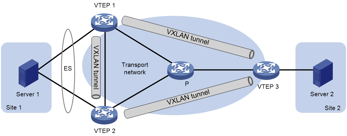
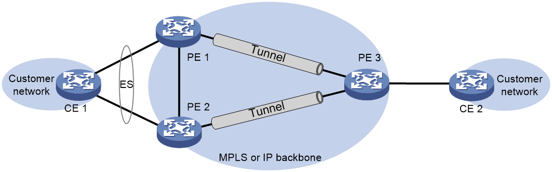
As shown in Figure 46, EVPN VPLS supports deploying multiple PEs at a site for redundancy and high availability. On the redundant PEs, Ethernet links connected to the site form an ES that is uniquely identified by an ESI. EVPN VPLS supports only dualhoming.
Figure 46 EVPN VPLS multihoming
DF election
To prevent redundant PEs from sending duplicate flood traffic to a multihomed site, a designated forwarder (DF) is elected from the PEs to forward flood traffic to the local site. PEs that fail the election are assigned the backup designated forwarder (BDF) role. BDFs do not forward flood traffic to the local site.
DF election can be performed by using a VLAN tag-based algorithm or preference-based algorithm.
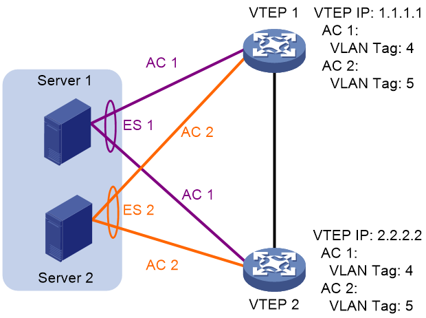
· VLAN tag-based DF election
PEs select a DF for each AC based on the VLAN tag and PE IP address as follows:
a. Arrange source IP addresses in Ethernet segment routes with the same ESI in ascending order and assign a sequence number to each IP address, starting from 0.
b. Divide the lowest VLAN ID permitted on an AC by the number of the redundant PEs, and match the reminder to the sequence numbers of IP addresses.
c. Assign the DF role to the PE that uses the IP address with the matching sequence number.
The following uses PE 1 and PE 2 in Figure 34 as an example to explain the DF election procedure:
a. PE 1 and PE 2 send Ethernet segment routes to each other.
b. The PEs assign sequence numbers 0 and 1 to IP addresses 1.1.1.1 and 2.2.2.2 in the Ethernet segment routes, respectively.
c. The PEs divide 4 (the lowest VLAN ID permitted by the ACs) by 2 (the number of redundant PEs), and match the reminder 0 to the sequence numbers of the IP addresses.
d. The DF role is assigned to PE 1 at 1.1.1.1.
Figure 48 VLAN tag-based DF election
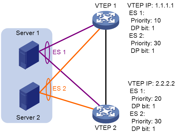
· Preference-based DF election
PEs select a DF for each ES based on the DF election preference, the Don't Preempt Me (DP) bit in Ethernet segment routes, and PE IP address. The DP bit can be set to one of the following values:
¡ 1—Non-revertive mode is enabled for preference-based DF election (DF preemption is disabled). A DF retains its role when a new DF is elected.
¡ 0—Non-revertive mode is disabled for preference-based DF election (DF preemption is enabled).
Preference-based DF election uses the following rules to select a DF for an ES:
a. The PE with higher preference becomes the DF.
b. If two PEs have the same preference, the PE with the DP bit set to 1 becomes the DF.
c. If both of the PEs have the DP bit set to 1, the PE with a lower IP address becomes the DF.
As shown in Figure 35, PE 2 is the DF for ES 1, and PE 1 is the DF for ES 2.
Figure 49 Preference-based DF election
Redundancy backup mode
The current device supports active-active redundancy mode, under which:
· Outbound traffic for multi-home site orientation: A multi-home site can access other sites through multiple PE in the redundancy backup group.
· Ingress traffic direction to multiple home sites: Unicast traffic from other sites can access multi-home sites through multiple PEs in the redundancy backup group; unknown unicast traffic, broadcast traffic, and multicast traffic from other sites can only access multi-home sites through the PE designated as DF in the redundancy backup group.
· Load sharing: Multiple PEs within the redundancy group can access each other between sites, and multiple reachable links exist between CEs, which can form load sharing.
Protocol packet exchange
Alias
Figure 50 Alias network diagram

As shown in Figure 50, in the multi-active redundancy mode, only one PE in the redundancy backup group may learn MAC addresses related to certain services. This can lead to a situation where the remote PE can only receive the MAC/IP release route from this PE for these MAC addresses. As a result, the remote PE cannot share the traffic load accessing these MAC addresses with other PEs in the redundancy backup group.
To address this issue, the EVPN multi-homing introduces the alias mechanism. That is, when only one PE in the redundancy backup group advertises the reachability of the CE side MAC address to the remote PE through MAC/IP route release, the remote PE can perceive the reachability of other PEs and the MAC address in the redundancy backup group based on the Ethernet autodiscovery route (carrying PE, ESI info etc.) transmitted by the PE within the group. As such, it generates the corresponding MAC entry, forming load sharing.
MAC address fast convergence
Figure 51 MAC address fast convergence
As shown in Figure 51, in the EVPN network, MAC address reachability is achieved by announcing MAC/IP release routes between PEs. Therefore, when there is a link fault between CE 1 and PE 1, PE 1 needs to undo the MAC/IP release routes one by one, which may result in a slower MAC address convergence speed in large-scale networks.
The EVPN multi-homing network provides a fast convergence mechanism, allowing the PE to reduce the convergence time by undoing an Ethernet autodiscovery route, announcing the unreachability of all MAC addresses in a specified ES, and notifying the remote PE to delete MAC address entries in bulk.
LDP PW or static PW access to EVPN PW
In real-world network setup, situations may arise where traditional VPLS network and EVPN VPLS network coexist. Through the function of LDP PW OR static PW accessing EVPN PW, by treating the LDP PW or static PW in the VPLS network as the AC of the EVPN VPLS network (this PW is called UPW), we achieve the mutual forwarding of packets between the EVPN PW and UPW, thereby achieving intercommunication between the VPLS network and the EVPN VPLS network.
This function not only supports a single LDP PW or static PW to access an EVPN PW, but also multiple affiliations of two LDP PWs or static PWs to two EVPN PWs. As shown in Figure 52, in the VPLS network, PE 1 establishes primary and backup LDP PW or static PW with PE 2 and PE 3, respectively, called UPW. In the EVPN VPLS network, PE 4 sets up EVPN PW with PE 2 and PE 3, respectively. UPW serves as an AC in the EVPN VPLS network. After PE 2 or PE 3 receives a message from UPW, it removes the MPLS encapsulation, looks up the MAC address table for the corresponding EVPN PW, adds corresponding MPLS encapsulation for EVPN PW to the message, and forwards it to PE 4. The method for PE 2 or PE 3 processing messages received from EVPN PW is similar.
Figure 52 LDP PW or static PW accessing EVPN PW network
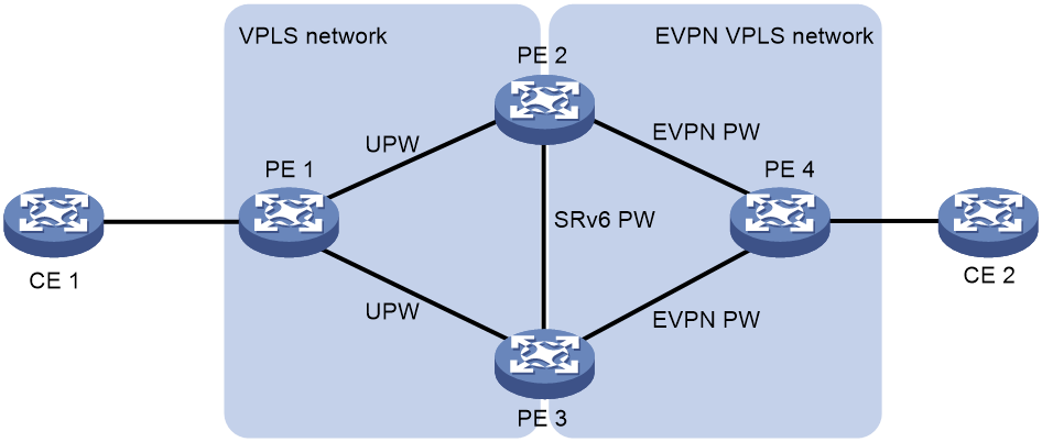
Typical network applications
Multihoming
In order to avoid disruptions in packet forwarding caused by a single point of failure in PE, EVPN VPLS typically adopts a multi-homing network approach. The traffic of the multi-homed sites is load shared among multiple PEs, that is, all PEs forward the traffic, to enhance network reliability.
Figure 53 Multihoming

E-Tree network
In an EVPN VPLS network configuration, all ACs belonging to the same VSI can access each other. To enhance the security of user services on the AC side and minimize their mutual impact in an EVPN VPLS network, network administrators may need to control the access between AC side users. The E-Tree function achieves traffic isolation between ACs within the same VSI by assigning them as either Root or Leaf roles.
· Users connected to the Leaf AC can only access those connected to the Root AC.
· Users connected to different Leaf ACs are isolated from each other.
· Users connected to the Root AC can access all other users connected to the AC within the VSI.
Figure 54 EVPN E-Tree network
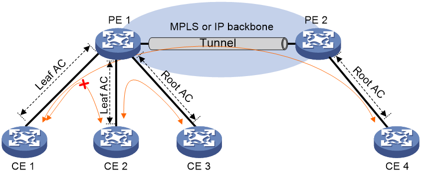
EVPN VPWS
Network model
Figure 55 EVPN VPWS network model
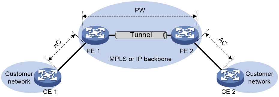
As shown in Figure 55, the typical network model of EVPN VPWS includes the following components:
· Customer edge (CE) devices—The devices at the edge of the customer network. They are directly connected to the service provider network.
· PE (Provider Edge): This is a device on the provider network side that is connected to CE. PE is primarily responsible for the access to EVPN services, completing the mapping and forwarding of packets from the customer network to the public network tunnel, and from the public network tunnel to the customer network.
· An attachment circuit (AC) is a physical or virtual circuit that connects a Customer Edge (CE) device to a Provider Edge (PE) device, such as Frame Relay's DLCI, ATM's VPI/VCI, Ethernet interface, VLAN, or a PPP connection on a physical interface.
· Pseudowire (PW): A virtual bidirectional connection between two PE points. The PW is composed of a pair of unidirectional virtual connections with opposite orientations.
· Public Network Tunnel: A tunnel that traverses an IP or MPLS backbone network, used to carry PWs (Pseudowires). A public network tunnel can carry multiple PWs, and it can be an LSP (Label Switched Path), GRE (Generic Routing Encapsulation) tunnel, or MPLS TE (Traffic Engineered) tunnel.
· Cross connect: A connection formed by the series connection of two physical circuits or virtual circuits, where the messages received from one physical or virtual circuit are directly switched to another for forwarding. Cross connect includes two methods: AC to AC cross connection and AC to PW cross connection.
EVPN VPWS control plane working mechanism
Overview of Working Mechanism
The working mechanism of EVPN VPWS control plane is:
1. Establish a public network tunnel; the public network tunnel is used to carry one or more PWs between PEs.
2. Establish a PW for transmitting specific customer network messages, where the PW label identifies the messages' associated user network.
3. Set up the AC to establish a connection between CE and PE. The matching rules of AC messages (explicitly configured or implied rules) determine which messages received from CE belong to a specific customer network.
4. Associate AC and PW so that the PE can determine to forward the received messages from AC to the designated PW and to forward the received messages from PW to the designated AC.
After completing the above tasks, the PE encapsulates the PW label into the messages from the customer network received through the AC, based on the PW associated with the AC, and forwards these messages to the remote PE through the public network tunnel. The remote PE, upon receiving the messages from the public network tunnel, determines the PW to which the messages belong based on the PW label, and then forwards the decoded original messages to the AC associated with this PW.
Public network tunnel establishment
The public network tunnel, which can be an LSP tunnel, MPLS TE tunnel, GRE tunnel, etc., is used to carry PW. The establishment methods of different tunnels vary. For detailed introduction, see the relevant manual.
When multiple public network tunnels exist between two PE, a tunneling policy can be configured to determine how to select a tunnel.
|
|
NOTE: If the PW is established on an LSP OR MPLS TE tunnel, the messages transmitted by the PW will include two layers of labels: The inner label is the PW label, used to determine the message's associated PW, and forward the message to the correct CE; the outer label is the public network LSP OR MPLS TE tunnel label, ensuring proper message transmission within the MPLS network. |
PW establishment
As shown in Figure 56, the process of establishing PW is as follows:
1. The Local service ID is configured on both PE 1 and PE 2 to identify the CE connected to it. The Remote service ID is configured to identify the CE connected to the remote PE. An MPLS label (i.e., PW label) is allocated for each Local service ID, which serves as the incoming label for PW.
2. The local PE (such as PE 1) advertises the Local service ID and the allocated PW label to the remote PE (such as PE 2) by passing the Ethernet Auto-discovery Per EVI route.
3. If the 'Export target' property in the route matches the 'Import target' property locally configured on PE 2, PE 2 will match the received 'Local service ID' to the locally configured 'Remote service ID'. If they match, a one-way LSP will be established from PE 2 to PE 1. The PW label advertised by PE 1 will be used as the output label for this LSP.
4. At the same time, PE 2 will transmit Ethernet Auto-discovery Per EVI route to PE 1. PE 1 will match the received Local service ID with the locally configured Remote service ID. If they are the same, a unidirectional LSP from PE 1 to PE 2 is established.
5. When two unidirectional LSPs with opposite orientation are established between the two PE endpoints, the EVPN PW setup is completed.
Figure 56 PW establishment
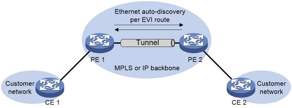
AC establishment
In EVPN VPWS, the AC is an Ethernet interface, Ethernet subinterface, or Ethernet service instance associated with a cross-connect. The Ethernet service instance is created on the Layer 2 Ethernet interface, defining a set of match rules to match the data frames received from this Layer 2 Ethernet interface.
Associating AC and PW
You can associate the Access Controller (AC) with the Pseudowire (PW) to the corresponding Layer 3 Ethernet interface, Layer 3 Ethernet subinterface, or Ethernet service instance via the command line. This allows messages received by this AC to be forwarded via the associated PW, and messages received from the associated PW to be forwarded via this AC.
EVPN VPWS data plane working mechanism
As shown in Figure 57, after receiving the message from AC/PW, the PE will search for the orientation PW or AC information within the corresponding cross connection, and thus determine how to forward the message.
· When the egress interface is a PW (Pseudowire) index, the message is encapsulated with a PW tag before adding the public network tunnel encapsulation, and then forwarded to the remote PE (Provider Edge) via PW. If the public network tunnel is an LSP (Label Switched Path) OR MPLS TE (Multi-Protocol Label Switching Traffic Engineering) tunnel, two layers of tags will be added to the message when it is forwarded via PW. The inner layer tag is the PW tag, used to forward the message to the corresponding PW; The outer layer tag is either the public network LSP or MPLS TE tunnel tag, which ensures correct transmission of the message between PEs.
· When the egress interface is the interface connecting to the local CE, the packets are directly passed to the local CE through the egress interface.
Figure 57 EVPN VPWS Packet Forwarding Process
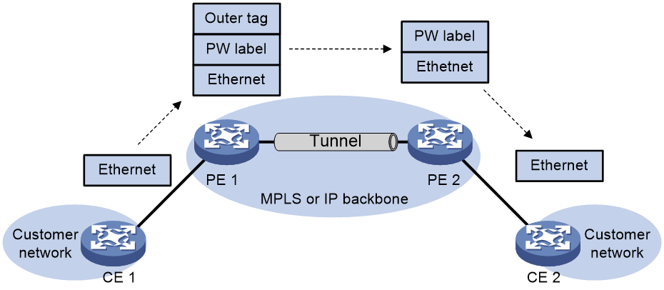
EVPN VPWS multihoming
About EVPN VPWS multihoming
When a site connects to multiple PE devices through different Ethernet links, these links form an Ethernet Segment (ES), identified by the same ES Identifier (ESI), indicating they belong to the same ES. The connected PEs form a redundancy backup group, which can prevent the impact of a single point failure on the network, thereby enhancing the network's reliability. Currently, only dual homing is supported.
Figure 58 EVPN VPWS multihoming
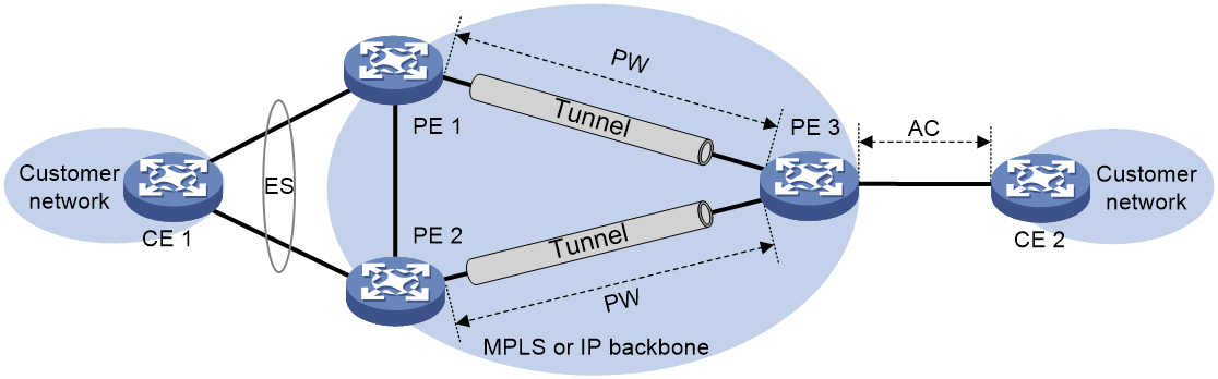
Redundancy backup mode
The redundancy backup modes supported in the EVPN VPWS networking scenario include: single-active redundancy mode and multi-active redundancy mode.
· Single active redundancy mode
As shown in Figure 59, under the single active redundancy mode, only one of PE 1 and PE 2 forwards traffic. The two PWs on PE 1 and PE 2 have a primary and backup relationship, which ensures that when the primary PW fails, the traffic is immediately switched to the backup PW, allowing traffic forwarding to continue. Through DF election, the primary and backup PWs can be determined. For a detailed description of DF election, see "DF Election Section 4.4.3". When the PW of PE 1 is not available (which could be due to a fault in PE 1 node or PW), PE 3 will enable the backup PW, forward the packets of CE 2 to PE 2 through the backup PW, and then PE 2 forwards them to CE 1. At the same time, it's recommended to configure a CLI monitoring policy for EAA and Track linkage on the physical interface of the PE 1 device's AC side and the physical interface of the PW side (used for establishing EVPN PW). This linkage ensures that when the Underlay network on the PW side is disconnected, the interface on the AC side is set to the Down state, ensuring that traffic from CE 1 to CE 2 is forwarded through PE 2.
Figure 59 Single active redundancy mode
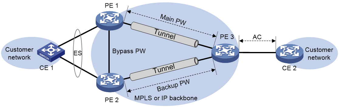
· Multi-active redundancy mode
In multi-active redundancy mode, two PWs share the load of forwarding datagrams equally. In this mode, a CLI monitoring policy that links EAA and Track is also required on the physical interface on the AC side of the PE device and the physical interface on the PW side (used to establish the EVPN PW) to enhance network reliability by linking these two interfaces.
DF election
In the single-active redundancy mode, the datagram is only transmitted through one PW. At this time, a PE needs to be elected as the Designated Forwarder (DF) from the redundancy backup group, and the PW created on this PE becomes the primary PW. Other PEs act as Backup DF (BDF), and the PWs they create are backup PWs. Multihomed members advertise ES and PE information to other PEs by transmitting Ethernet network segment routes. Only the PEs configured with ESI receive the Ethernet network segment routes and elect the DF based on the carried ES and PE information.
The device supports a variety of DF election algorithms. Users can flexibly select the DF election algorithm based on business needs, allowing DF to be evenly distributed in the network group, thereby improving the utilization rate of network equipment.
Algorithm for DF election based on VLAN Tag
The DF election algorithm based on VLAN Tag elects a DF for each AC based on the VLAN Tag and the IP address of VTEP.
Figure 60 DF election based on VLAN Tag

As shown in Figure 60, taking the example of allowing AC 1 to pass VLAN Tag 4 for DF election, the DF election algorithm based on VLAN Tag is as follows:
1. The minimum VLAN Tag allowed within the AC is selected to represent the AC. In this case, VLAN Tag 4 represents AC 1.
2. VTEP sorts the source IP addresses in the routes with the same ESI it receives based on the Ethernet network segment routing in ascending order, and the numbering starts from 0. In this example, the source IPs 1.1.1.1 and 2.2.2.2 have corresponding numbers 0 and 1, respectively.
3. The DF is elected based on the remainder M of the VLAN Tag divided by N, where N represents the number of members in the redundancy backup group, and M corresponds to the DF of the respective AC. In this example, the remainder of 4 divided by 2 is 0, which means the DF of AC 1 is VTEP 1 with the number 0.
Priority-based DF election algorithm
The priority-based DF election algorithm elects the DF for each ES according to the DF election privilege level, DP (Don't Preempt Me) value and IP address of the VTEP. The DP value comprises:
· This denotes that the privilege level-based DF election algorithm function has been activated and will not be switched back. This means that even if a new device is elected as DF subsequently, the current device will still be used as DF.
· /n0 indicates that the function of not switching back based on the privilege level DF election algorithm has been turned off. That is, if the current device is elected as DF, and a new device is later elected as DF, the new device will be directly used as DF.
Figure 61 DF election based on privilege level

As shown in Figure 61, taking the DF election of ES 1 and ES 2 as an example, the DF election algorithm based on privilege level is as follows:
1. Within the same Ethernet Segment (ES), the VTEP with the highest privilege level (the larger the value, the higher the privilege level) is chosen as the Designated Forwarder (DF) for that ES. In this case, VTEP 2 is elected as the DF for ES 1.
2. If the privilege levels are identical, the VTEP with a DP bit of 1 serves as the DF.
3. If the DP position is the same, the VTEP with the smaller IP address will serve as the DF. In this example, VTEP 1 was chosen as the DF for ES 2.
Protocol packet exchange
Mechanism of backup path under single active redundancy mode
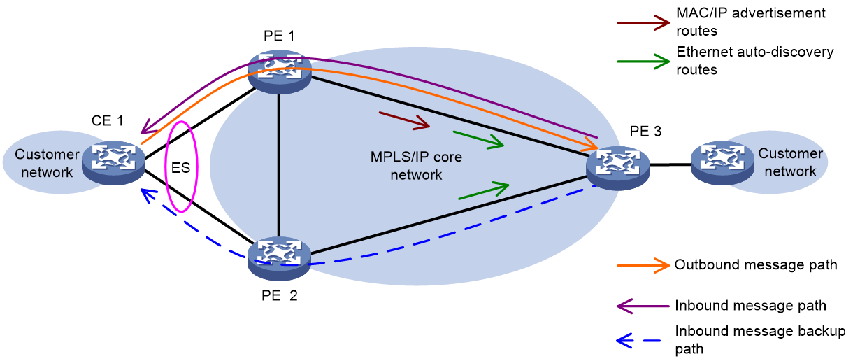
As shown in Figure 62, in the single active redundancy mode, only the DF can learn the MAC addresses within multiple belonging sites. This causes PE 3 to only receive the MAC/IP route release from DF for these MAC addresses. If the DF encounters a fault, PE 3 needs a longer time to relearn the entry guide messages for these MAC addresses for forwarding.
EVPN introduces a backup path mechanism to solve the aforementioned issue. The backup path mechanism means that when the PE acting as DF in the redundancy backup group advertises the reachability of the CE-side MAC address by releasing MAC/IP routes to the remote PE, the remote PE can perceive the reachability of the BDF and MAC address in the redundancy backup group based on the Ethernet autodiscovery route (carrying PE, ESI, etc.) transmitted by the PE. This forms a backup path for the remote PE to reach CE 1 through BDF. When a DF fault occurs, the redundancy backup group directly switches the forwarding path to the backup path passing through BDF, without having to relearn the MAC address entry.
Alias mechanism under the multi-active redundancy mode
Figure 63 Alias network diagram
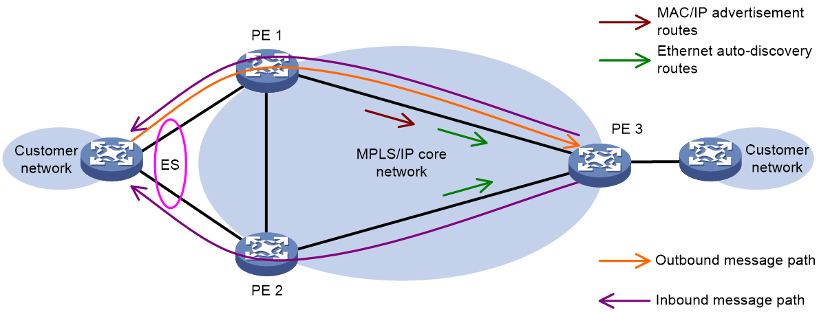
As shown in Figure 64, in the multi-active redundancy mode, only one PE in the redundancy backup group might learn some business-related MAC addresses. This would result in the remote PE only receiving the MAC/IP release route for these MAC addresses from this PE. Therefore, the remote PE cannot share the traffic load of accessing these MAC addresses to other PEs in the redundancy backup group.
To address this issue, EVPN multi-homing introduces the alias mechanism. When only one PE in the redundancy backup group advertises the reachability of the CE-side MAC address to the remote PE through MAC/IP route release, the remote PE can perceive the reachability of other PEs and MAC addresses within the redundancy backup group based on the Ethernet autodiscovery routes (carrying PE, ESI, and other information) transmitted by the PEs. This leads to the generation of corresponding MAC address entries and the formation of load sharing.
Multi-segment PW
Multi-section PW refers to concatenating two or more PWs to form an end-to-end PW. By creating two PWs under the same cross-connect, it is possible to concatenate the two PWs under this cross-connect. After a PE receives a message from a PW, it removes the tunnel ID and the PW label from the message, encapsulates another PW label that is connected with this PW, and forwards the message via the public network tunnel that carries this PW. This allows the message to be forwarded between the two PWs.
As shown in Figure 64, by connecting PW 1 and PW 2 on PE 2, and PW 2 and PW 3 on PE 3, an end-to-end PW can be established from PE 1 to PE 4. This allows messages to be forwarded between PE 1 and PE 4 along the multi-section PW formed by PW 1, PW 2 and PW 3.
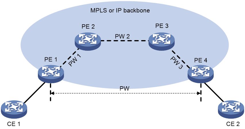
Multi-segment PW is divided into:
· In-domain multi-section PW: Deploying multiple PW sections within an autonomous system (AS).
In an autonomous system (AS), deploying multiple sections of PW can establish end-to-end PW between two PEs without relying on an existing end-to-end public network tunnel.
As shown in Figure 66, there is no public network tunnel established between PE 1 and PE 4, but there are public network tunnels established between PE 1 and PE 2, and PE 2 and PE 4. By establishing a PW (PW 1 and PW 2) between PE 1 and PE 2, and PE 2 and PE 4 respectively, and linking these two PWs on PE 2, an end-to-end multi-section PW consisting of two PW sections can be established between PE 1 and PE 4.
By establishing multi-section PW within the domain, the existing public network tunnels can be fully utilized, reducing the number of end-to-end public network tunnels.
Figure 65 Multi-segment PW within the AS
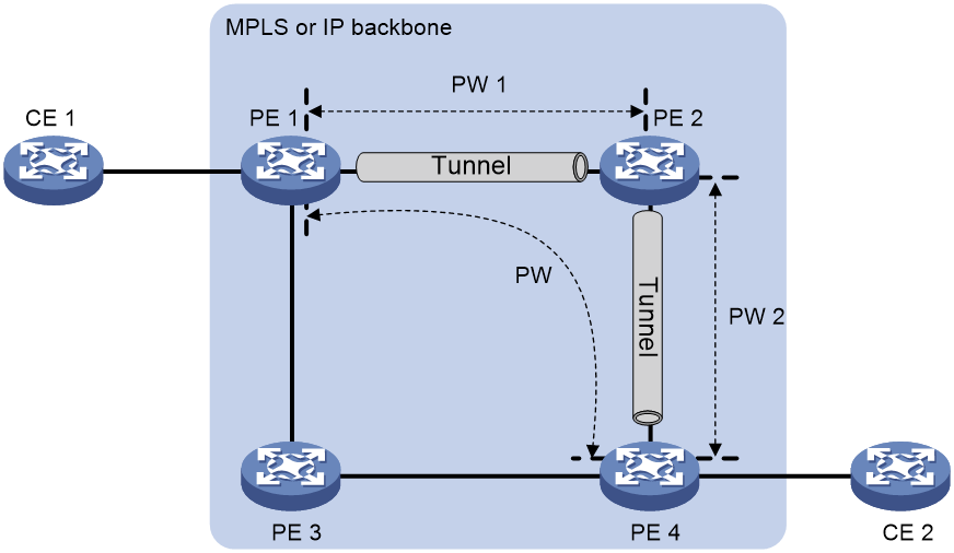
· Inter-AS multi-section PW: That is to say, multiple PW sections are deployed across the autonomous system (AS). For a detailed introduction of the inter-domain multi-section PW, see "Cross-Domain-Option B".
EVPN and VPWS inter-AS
In actual networking applications, different sites may communicate through multiple providers with different AS numbers or across multiple autonomous systems (AS) of a single provider. This mode of application across multiple AS is called EVPN VPWS inter-domain.
The EVPN VPWS cross-domain solution can be divided into the following types:
· The EVPN routes are established and released between PE and ASBR via MP-IBGP (IBGP redistribution of EVPN routes between PE and ASBR), building up the EVPN PW. ASBR functions as CE, and on ASBR, AC is associated with EVPN PW, which is also referred to as Inter-Provider Option A.
· EVPN routes are established via EVPN PW by releasing MP-IBGP between the PE and ASBR. Also, EVPN PW is set up by releasing MP-EBGP (EBGP redistribution of EVPN routes between ASBRs) among ASBRs, also known as Inter-Provider Option B.
· PE routers establish EVPN PW by releasing EVPN routes through MP-EBGP (Multi-hop EBGP redistribution of EVPN routes between PE routers), also known as Inter-Provider Option C.
Inter-AS option A
As shown in Figure 66, in this mode, the PE routers of the two autonomous systems (AS) are directly connected and act as the border routers (BR) of their respective AS. Both BRs treat each other as their CE devices and associate the interfaces connected with the opponent BR with EVPN PW to realize packet forwarding across domains.
The advantage of this method is its simplicity. No special configuration is required between the two Provider Edge routers serving as Autonomous System Border Routers (ASBRs) for cross-domain. However, its drawback is poor expandability: it requires configuring Attachment Circuit for each cross-domain site on both ASBRs and binding it with EVPN PW, which is complex and difficult to manage.
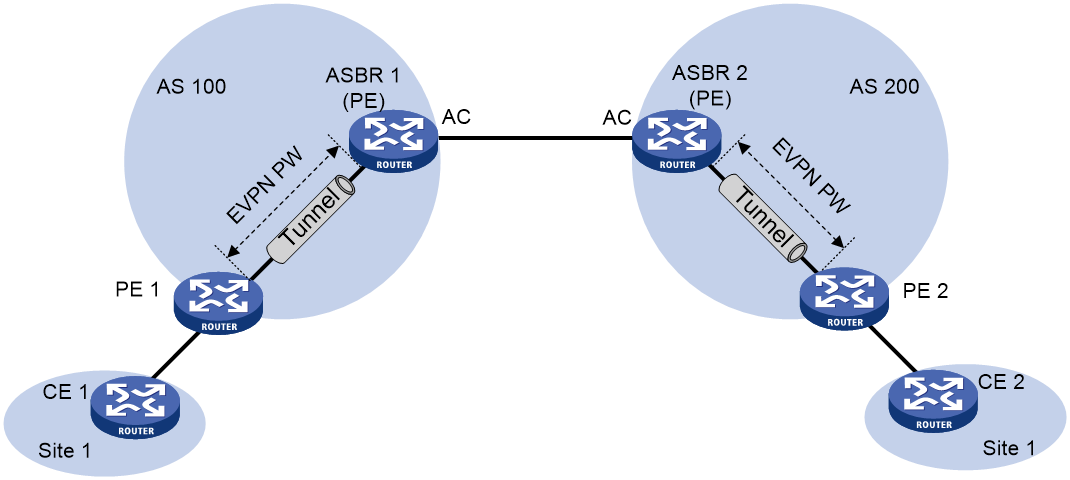
Inter-AS option B
As shown in Figure 67, in this method, EVPN routes are established between PE 1 and ASBR 1, and ASBR 2 and PE 2 respectively via MP-IBGP release. An EVPN PW is also established between ASBR 1 and ASBR 2 through the MP-EBGP release of EVPN routes. The cross-domain transmission of messages can be achieved by concatenating multiple EVPN PWs.
The expansion of this method is superior to Inter-Provider Option A. However, the drawback is that the ASBR still needs to configure multiple sections of PW for each cross-domain site.
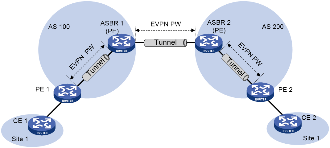
Inter-AS option C
In this method, multi-hop MP-EBGP sessions are established between PEs of different AS, and EVPN routes are released directly between PEs to create EVPN PW via these sessions. At this point, one end of the PE needs to have a route to reach the remote PE and the corresponding label for this route to facilitate the establishment of a public network tunnel across the AS between two PEs. Inter-Provider Option C establishes a public network tunnel in the following manner:
· Using the LDP or other label distribution protocols, establish a public network tunnel within the AS.
· The ASBR passes labeled IPv4 unicast routes through BGP, establishing public network tunnels across AS domains. Labeled IPv4 unicast routes refer to the allocation of MPLS labels to IPv4 unicast routes, while simultaneously releasing IPv4 unicast routes and labels, in order to associate routes and labels.
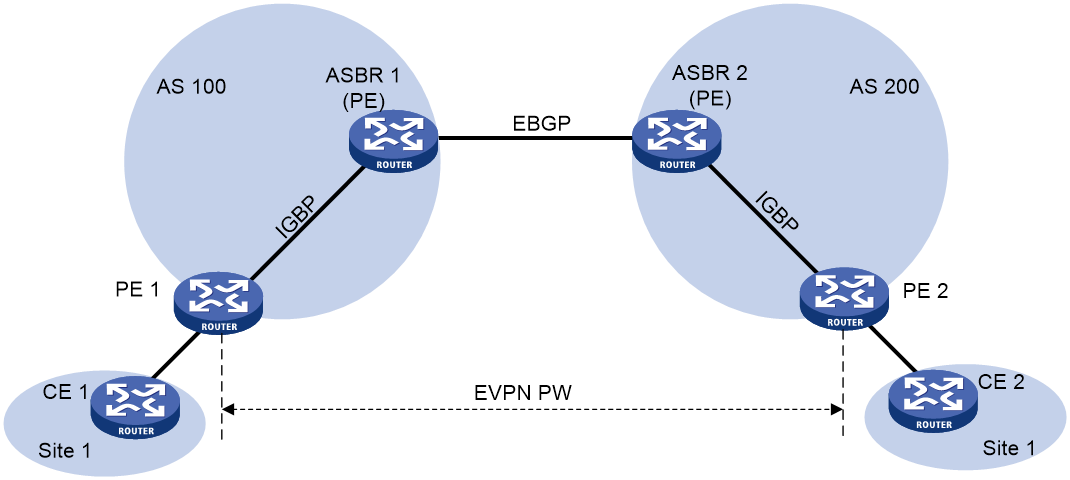
As shown in Figure 68, the difficulty of Inter-Provider Option C is to establish a public network tunnel across AS domains. Taking the example of PE 2 to PE 1, the process of establishing a public network tunnel is as follows:
1. In AS 100, a public network tunnel from ASBR 1 to PE 1 is established using label distribution protocols such as LDP. Assume that the outgoing label of this public network tunnel on ASBR 1 is L1.
2. ASBR 1 releases labeled IPv4 unicast routes to ASBR 2 through an EBGP session, passing the route corresponding to PE 1's address and the allocated label (assumed to be L2) from ASBR 1. The next-hop address for the route is ASBR 1. This way, a public network tunnel is established from ASBR 2 to ASBR 1, with the ingress label of the public network tunnel on ASBR 1 being L2.
3. ASBR 2 releases IPv4 unicast routes with labels through the IBGP session to PE 2, allocating the route corresponding to the PE 1 address and the label allocated by ASBR 2 (assumed to be L3) to PE 2, with the next-hop address being ASBR 2. In this way, a public network tunnel is established directly from PE 2 to ASBR 2. The inbound label of the public network tunnel on ASBR 2 is L3, and the outbound label is L2.
4. MPLS packets cannot be directly forwarded from PE 2 to ASBR 2. Within AS 200, another public network tunnel from PE 2 to ASBR 2 needs to be established hop-by-hop using label distribution protocols such as LDP. Assume that the outbound label of the public network tunnel on PE 2 is Lv.
After the establishment of the public network tunnel, the EVPN route is established through multi-hop MP-EBGP sessions released between PE 1 and PE 2 to set up the EVPN PW. By associating the EVPN PW with AC on PE 1 and PE 2, cross-domain forwarding of messages can be realized.
To reduce the number of IBGP connections, a route reflector (RR) can be designated within each AS, which exchanges EVPN routing information with PE in the same AS, with the RR storing all EVPN routes. Multi-hop MP-EBGP sessions are established between RRs of two ASs to advertise EVPN routes.
Both Inter-Provider Option A and Inter-Provider Option B require ASBR to participate in the maintenance and release of EVPN routes. When each AS has a large number of EVPN routes to switch, ASBR may become a bottleneck hindering further network expansion. In Inter-Provider Option C, PEs directly switch EVPN routes between them, demonstrating excellent scalability.
LDP PW or static PW access to EVPN PW
In actual network configuration, there might be a coexistence of traditional MPLS L2VPN network (also known as VPWS network) and EVPN VPWS network. The function of LDP PW or static PW accessing EVPN PW is accomplished by treating LDP PW OR static PW in MPLS L2VPN network as the AC (access circuit) of EVPN VPWS network (this PW is called UPW). This enables message forwarding between EVPN PW and UPW, thereby achieving interoperability between MPLS L2VPN network and EVPN VPWS network.
This function not only supports a single LDP PW or static PW connected to an EVPN PW, but also supports two LDP PWs or static PWs with multiple affiliations connected to two EVPN PWs.In an MPLS L2VPN network, PE 1 establishes primary and backup LDP PWs or static PWs with PE 2 and PE 3, which are called UPWs. In the EVPN VPWS network, PE 4 establishes EVPN PWs with PE 2 and PE 3. UPWs serve as ACs in the EVPN VPWS network. After PE 2 or PE 3 receives packets from UPWs, they remove the MPLS encapsulation, look for associated EVPN PWs, add the corresponding MPLS encapsulation to the packets, and forward them to PE 4. The processing method for PE 2 or PE 3 receiving packets from EVPN PWs is similar.
Figure 69 LDP PW or static PW access to EVPN PW
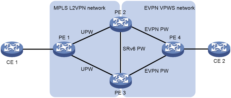
Typical network applications
Multihoming
To avoid the disruption in message forwarding caused by single point failure of PE, EVPN VPWS usually adopts multi-home networking mode. The traffic of multi-home sites can form primary and backup backups among multiple PEs, meaning only one PE forwards traffic at a time; or load sharing can be conducted among multiple PEs, meaning all PEs are forwarding traffic.
Figure 70 Multihoming network diagram

FRR
To mitigate the impact of AC link or PW link faults on the network and enhance the network's reliability and stability, the FRR function can be deployed in the EVPN VPWS network group. The FRR function includes the following two types:
· Bypass PW refers to a function that can reduce package loss caused by link faults in the AC. For instance, when the AC link on the PE 2 side has a fault, PE 2 will temporarily redirect the traffic to PE 3 using Bypass PW. Then, PE 3 forwards it to CE 2.
· Primary and backup PW: These are two EVPN PWs established between PE nodes as a mutual backup. One of them is the primary PW and the other one is the backup PW. For instance, if the primary PW between PE 1 and PE 2 fails, PE 1 will switchover the traffic to the backup PW for forwarding to PE 3, which then forwards it to CE 2.
Figure 71 FRR network diagram
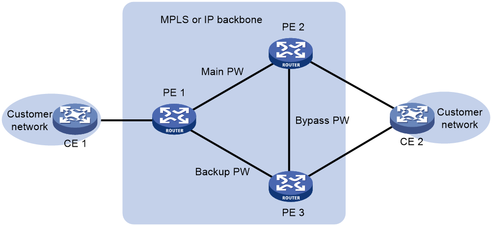
EVPN L3VPN
EVPN L3VPN network model
In EVPN, IP prefix routing can be used to release private network route information for VPNs, enabling the deployment of MPLS L3VPN groups. This network is referred to as EVPN L3VPN. Compared to BGP/MPLS L3VPN networks, EVPN L3VPN group deployment can quickly deploy large Layer 2 networks based on EVPN, allowing the network to carry both Layer 2 VPN and Layer 3 VPN services simultaneously.
Figure 72 EVPN L3VPN network model
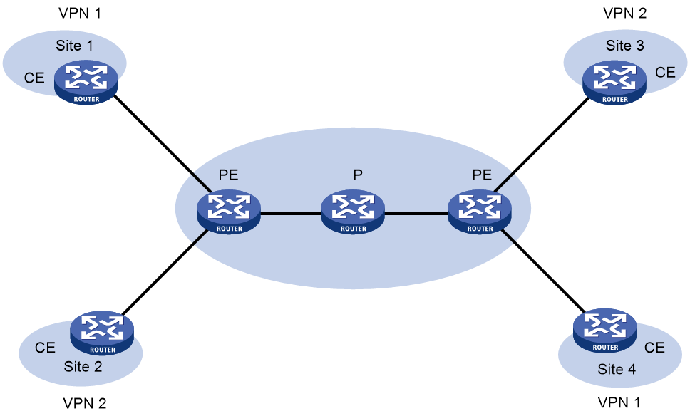
As shown in Figure 72, an EVPN L3VPN network contains the following types of network elements:
· Customer edge (CE) devices: The devices at the edge of the customer network. They are directly connected to the service provider network.
· Provider Edge (PE): A device on the provider network side connected to the customer's device. The PE is primarily responsible for facilitating the access to EVPN L3VPN services, accomplishing the mapping and forwarding of the data packets from the customer network to the public network tunnel, and from the public network tunnel back to the customer network.
EVPN L3VPN control plane working mechanism
In the networking of EVPN L3VPN group, the release of VPN routing information involves CE and PE. The P router only maintains the routes of the backbone network and does not need to understand any VPN routing information. The PE router only maintains the routing information of the VPN directly connected to it, not maintaining all VPN routes.
VPN routing information is advertised along the local CE—ingress PE—egress PE—remote CE path for CEs at different sites to establish routed connectivity.
Route advertisement from the local CE to the ingress PE
The CE advertises the VPN routes for the local site as standard IPv4 or IPv6 routes to the ingress PE through static routing, RIP, OSPF, IS-IS, EBGP, or IBGP.
Route advertisement from the ingress PE to the egress PE
After learning the VPN routing information from CE, PE stores it in the routing table of the corresponding VPN-instance. PE adds RD and Export Target properties to these standard IPv4 OR IPv6 routes, and allocates MPLS private network labels to them, forming the EVPN IP prefix routes (including RD, Export Target properties, and MPLS private network labels) that are released to the exit PE. The exit PE matches the Export Target properties of the IP prefix routes with the Import Target properties of the VPN-instance it maintains. If the Import Target properties of a VPN-instance on the exit PE match the Export Target properties in the route, the exit PE receives this IP prefix route and adds it to the VPN routing table.
Route advertisement from the egress PE to the remote CE
The remote CE learns VPN routes from the egress PE through static routing, RIP, OSPF, IS-IS, EBGP, or IBGP.
EVPN L3VAN data plane working mechanism
In an EVPN L3VPN network, a PE inserts the following labels into a VPN packet when it forwards that packet:
· Outer label: Also known as the public network label. VPN messages are transmitted along the public network tunnel on the backbone network from one end's PE to the other end's PE. The public network tunnel can be an LSP tunnel, an MPLS TE tunnel, or a GRE tunnel. When the public network tunnel is an LSP tunnel or an MPLS TE tunnel, the public network label is an MPLS label, called the public network label; when the public network tunnel is a GRE tunnel, the public network label is GRE encapsulation.
· Inner label, also known as private network label, is used to indicate to which Site a message should be sent. The remote PE can determine the VPN instance to which the message belongs based on the private network label. By looking up the routing table of this VPN instance, the message can be correctly forwarded to the corresponding Site. When releasing EVPN routes between PEs, the private network label allocated for private network routes will be advertised to the remote PE.
Figure 73 EVPN L3VPN traffic forwarding
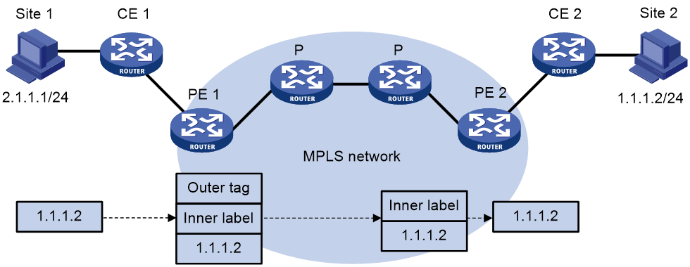
As shown in Figure 73, a VPN packet is forwarded from Site 1 to Site 2 by using the following process:
1. Site 1 transmits an IP packet with a destination address of 1.1.1.2, and CE 1 sends the packet to PE 1.
2. PE 1 checks the routing table of the corresponding VPN-instance based on the interface where the packet arrives and the destination address. It adds the private network tag to the packet according to the matched route table entry, and finds that the next hop for the packet is PE 2.
3. PE 1 searches the public network routing table to find the route to PE 2. Based on the search results, it encapsulates the message with a public network label or performs a GRE encapsulation, and then forwards the message along the public network tunnel.
4. Within the MPLS network, P forwards the packet based on the public network tag, sending the packet to PE 2. If the public network tag is an MPLS label, it will be stripped off at the hop before reaching PE 2, leaving only the private network label. If it uses GRE encapsulation, PE 2 will strip off the GRE encapsulation of the packet.
5. PE 2 identifies the VPN-instance to which the message belongs based on the private network label, determines the egress interface of the message by examining the VPN-instance's routing table, and after stripping the private network label, forwards the message to CE 2.
6. The CE 2 forwards the message to the destination host following the normal IP forwarding process.
When two sites of a VPN are connected to the same PE, the PE directly forwards packets between the two sites through VPN routing table lookup without adding any tag or label.
Interconnection between BGP/MPLS L3VPN and EVPN L3VPN
In the process of transforming the current L3VPN network into an EVPN L3VPN network, there can be two types of network interfacing scenarios. By deploying BGP VPNv4 or BGP VPNv6 route passing through BGP EVPN's IP prefix route release function to its neighbors and EVPN route through BGP VPNv4 OR BGP VPNv6 address family release to neighbor function on PE 3, we can establish reachable routes across MPLS L3VPN and EVPN L3VPN networks between CE 1 and CE 2, and conduct communication.
The interconnection of BGP/MPLS L3VPN and EVPN L3VPN is divided into two parts:
· Deploy the BGP VPNv4 or BGP VPNv6 route on PE 3 and release the IP prefix route to the neighbor function via BGP EVPN. This enables the routing of Site 1 to be passed through the MPLS L3VPN network to the EVPN L3VPN network, and then released to Site 2. The specific process is as follows:
a. After learning the VPN routing information from CE 1, PE 1 saves it into the VPN-instance's routing table. Concurrently, it assigns a Route Distinguisher to these IPv4 OR IPv6 routes, forming VPNv4 OR VPNv6 routes.
b. PE 1 releases VPNv4 or VPNv6 routes to PE 3 via MP-BGP. The route carries VPN Target properties and MPLS private network tags.
c. Upon receiving VPNv4 or VPNv6 routes, PE 3 matches the Export target in the routes with the Import target of the local VPN-instance. If there is a matching value between the two, the route will be added to the routing table of that VPN-instance.
d. On PE 3, the IPv4 or IPv6 routes in the VPN-instance routing table are translated into EVPN IP Prefix routes. The next-hop address for these routes is PE 3, and the routes carry the VPN Target properties and information such as the MPLS private network label for that VPN.
e. PE 3 transmits the IP Prefix route to PE 2.
f. After PE 2 receives the IP Prefix route, if the route passes the VPN Target properties match, it adds the route to the routing table of the VPN-instance.
g. PE 2 releases IPv4 or IPv6 routes to CE 2.
· Deploy the EVPN route function on PE 3, where it releases through BGP VPNv4 OR BGP VPNv6 address family to its neighbors. The function enables the route of site 2 to be disseminated through the EVPN L3VPN network to the MPLS L3VPN network, and then released to site 1. The specific process is:
a. After PE 2 learns the VPN routing information from CE 2, it saves the information to the routing table of the VPN instance.
b. PE 2 translates the IPv4 or IPv6 routes in the VPN-instance routing table into an EVPN IP Prefix route, with PE 2 as the next-hop address. The route carries information such as the VPN Target properties and the MPLS private network labels of the VPN.
c. PE 2 releases this route to PE 3.
d. Upon receiving an IP Prefix route, PE 3 adds the route to the VPN-instance routing table if the VPN Target properties match.
e. PE 3 translates IPv4 or IPv6 routes from the VPN-instance routing table into VPNv4 or VPNv6 routes and releases them to PE 1. The routes carry VPN Target properties and MPLS private network labels.
f. After PE 1 receives a VPNv4 or VPNv6 route, if the route matches the VPN Target property, it is added to the routing table of the VPN instance.
g. PE 1 releases IPv4 OR IPv6 route to CE 1.
BGP EVPN fast reroute
When a link or a router in the EVPN network experiences a fault, messages that need to be transmitted through the faulty link or router to reach their destination will be lost or generate a routing loop, thereby disrupting the data flow. The disrupted traffic can only restore normal transmission after the routing converges according to the new network topology.
With the FRR function of BGP EVPN, the duration of traffic disruption due to network outages can be minimized as much as possible. After the fast reroute function is enabled under the BGP EVPN address family, BGP automatically calculates backup routes for all routes of the EVPN address family. That is, as long as routes to the same destination network are learned from different BGP peers and these routes are not equivalent, a primary and a backup route will be generated. When the primary route is unreachable, BGP uses the backup route to guide packet forwarding, greatly shortening the traffic disruption time. While using the backup route to forward packets, BGP re-evaluates the routes. After optimization, it uses the new optimal route to guide packet forwarding.
Once FRR is configured on the ingress node PE 1, PE 1 will compute that PE 3 is the backup next hop for PE 2. When PE 1 receives BGP EVPN IP prefix routes to CE 2 released by PE 2 and PE 3, PE 1 will log these two BGP EVPN IP prefix routes. The route released by PE 2 will be treated as the main path, and the route released by PE 3 will be treated as the backup path.
Configure the BFD detection of LSP OR MPLS TE tunnel function on PE 1 to monitor the public network tunnel state between PE 1 and PE 2. When the public network tunnel works normally, CE 1 and CE 2 communicate via the main path CE 1 - PE 1 - PE 2 - CE 2. When PE 1 detects a fault in the public network tunnel, PE 1 will forward CE 1's traffic to access CE 2 through the backup path CE 1 - PE 1 - PE 3 - CE 2. During this process, PE 1 is responsible for the primary path detection and traffic switchover.
Related documentation
· RFC 7432: BGP MPLS-Based Ethernet VPN
· draft-ietf-bess-evpn-overlay: A Network Virtualization Overlay Solution using EVPN
· draft-ietf-bess-evpn-prefix-advertisement: BGP MPLS-Based Ethernet VPN
· draft-ietf-bess-evpn-igmp-mld-proxy: IGMP and MLD Proxy for EVPN
· draft-boutros-l2vpn-vxlan-evpn: VXLAN DCI Using EVPN
· draft-ietf-bess-srv6-services: SRv6 BGP based Overlay services