- Released At: 26-07-2023
- Page Views:
- Downloads:
- Table of Contents
- Related Documents
-
|
H3C SecPath |
|
Quick Deployment Guide |
|
|
|
|
Document version: 6W100-20230724
Copyright © 2023 New H3C Technologies Co., Ltd. All rights reserved.
No part of this manual may be reproduced or transmitted in any form or by any means without prior written consent of New H3C Technologies Co., Ltd.
Except for the trademarks of New H3C Technologies Co., Ltd., any trademarks that may be mentioned in this document are the property of their respective owners.
The information in this document is subject to change without notice.
About the firewall quick deployment guide
Configuring basic firewall settings
Obtaining the factory default settings
Application scenario-based networking
Logging in to the Web interface
Internet access in routing mode
Internet access through a specific IP address
Internet access in transparent mode
Configuring signature library upgrade
Configuring automatic signature library upgrade
Triggering a signature library upgrade
Performing a manual signature library upgrade
Activating and installing a license for the first time
Restoring the factory defaults
About the firewall quick deployment guide
This guide helps you to have a preliminary understanding of the use of a firewall and complete the basic settings of the firewall, including the following:
· Common networking methods of the firewall.
· Quickly connect the firewall to the Internet.
· Quickly provide the security protection for enterprise networks.
· Common operation and maintenance measures of the firewall.
If you want to further understand and use more abundant security protection functions of the firewall, refer to the manual of the corresponding product.
This guide uses the feature 8590P06 version of the F100-C-A1 device as an example. The configuration interfaces and configurations might differ depending on the hardware model or software version.
This guide applies to the following models and versions:
F5000 series
|
F5000 series |
Model |
|
F50X0 series |
F5010, F5020, F5040, F5030, F5030-6GW, F5030-6GW-G, F5060, F5080, F5000-M, F5000-A, F5000-C, F5000-S |
|
F5000-AI series |
F5000-AI-15, F5000-AI-20, F5000-AI-40 |
F1000 series
|
F1000 series |
Models |
|
F1000-AI-X0 series |
F1000-AI-03, F1000-AI-10, F1000-AI-20, F1000-AI-30, F1000-AI-50, F1000-AI-60, F1000-AI-70, F1000-AI-80, F1000-AI-90 |
|
F1000-AI-X5 series |
F1000-AI-05, F1000-AI-15, F1000-AI-25, F1000-AI-35, F1000-AI-55, F1000-AI-65, F1000-AI-75 |
|
F1000-X-G3 series |
F1000-A-G3, F1000-C-G3, F1000-E-G3, F1000-S-G3 |
|
F10X0 series |
F1003-C, F1003-M, F1003-S, F1005, F1010, F1020, F1030, F1050, F1060, F1070, F1080, F1090 |
F100 series
|
F100 series |
Models |
|
F100-C-A series |
F100-C-A6-WL, F100-C-A5-W, F100-C-A3-W, F100-C-A6, F100-C-A5, F100-C-A3, F100-C-A1, F100-C-A2 |
Chassis views
The chassis views vary by firewall model. For more information about the chassis views, see the installation guide for the product. This section uses the F100-C-A1 firewall as an example.
Front panel
The F100-C-A1 firewall provides the following ports on the front panel:
· Two 1000BASE-X Ethernet fiber ports.
· Five 10/100/1000BASE-T autosensing Ethernet copper ports (including one management Ethernet port).
· One USB port.
· One console port.
· One Micro SD card slot.
Figure 1 Front panel

|
(1) 10/100/1000BASE-T copper ports |
(2) 1000BASE-X fiber ports |
|
(3) Console port |
(4) USB port (host mode, Type A) |
|
(5) Micro SD card slot |
(6) Reset button |
|
(7) DC-input power receptacle |
(8) Micro SD card, system status (SYS), and power status (PWR) LEDs |
|
(9) 1000BASE-X fiber port LED |
(10) 10/100/1000BASE-T Ethernet copper port LED |
|
(11) Management Ethernet port (MGMT) |
|
|
|
NOTE: The reset button restarts the firewall. It does not restore the factory defaults. |
Rear panel
Figure 2 Rear panel

|
(1) Grounding screw |
Mechanism of firewalls
About firewalls
A firewall is a network security device typically located at the network perimeter to isolate networks with different security levels as needed, protecting one network against attacks and intrusions from another network. You can configure the firewall to permit valid traffic and deny invalid traffic.
A firewall controls network traffic mainly based on security zones and security policies.
Interfaces and security zones
As shown in Figure 3, you can configure security zones to implement security zone-based security management. A security zone is a logical concept that indicates a collection of interfaces that have the same security requirements.
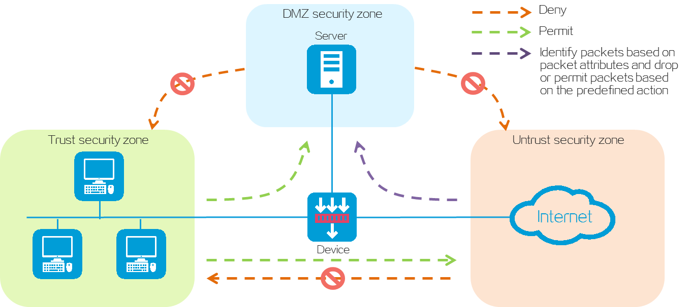
A firewall device provides default security zones Local, Management, Trust, DMZ, and Untrust. Default security zones cannot be deleted. The function and application scenario of each default security zone are as follows:
· Local—Refers to the device itself. You cannot add interfaces to security zone Local. For communication between a non-Management security zone and the device, you must configure a security policy to permit the packets between the corresponding security zone and security zone Local.
· Management—Refers to the security zone used for managing the device. The device permits packets between security zones Management and Local by default and you do not need to configure a security policy. By default, the device management interface belongs to security zone Management. You can log in to the device management interface to configure the device from a PC.
· Trust—Refers to the trusted security zone. You can assign the interface connected to the internal network to security zone Trust and configure a security policy to perform threat detection on incoming packets from other security zones. In this way, you can protect internal hosts and strictly control outgoing packets destined for other security zones to prevent data leakage.
· DMZ—A demilitarized zone is an isolated security zone that typically incorporates the interfaces connected to various public services or resources (such as Web servers or FTP servers). You can configure a security policy to audit packets sent to security zone DMZ from other security zones, so as to protect the servers from attacks and prevent data theft.
· Untrust—Refers to the untrusted network security zone. You can assign the interface connected to the Internet to security zone Untrust and configure a security policy to strictly detect packets sent to other security zones, so as to block external attacks and threats such as viruses.
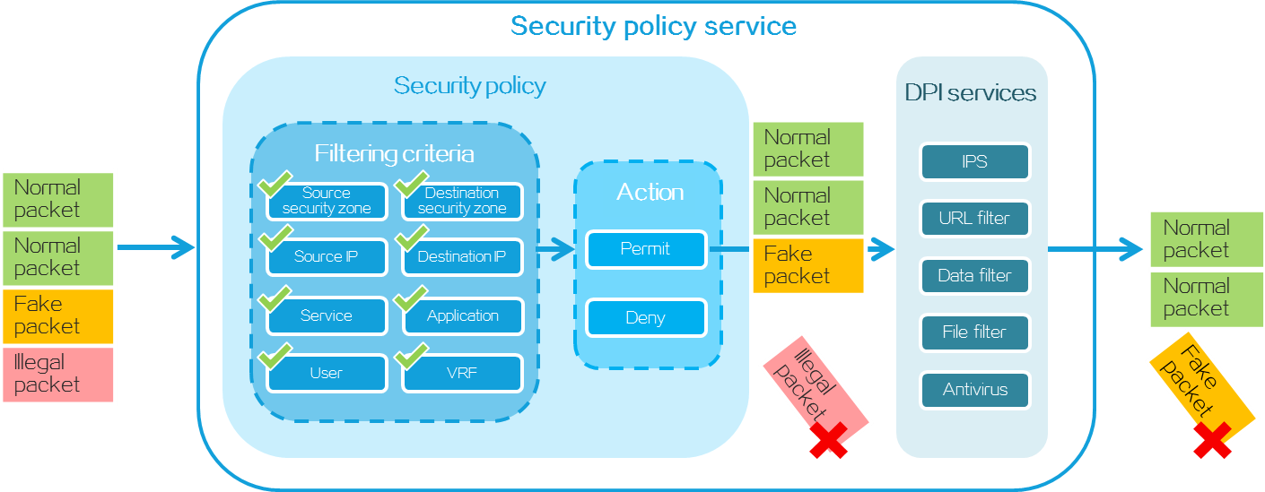
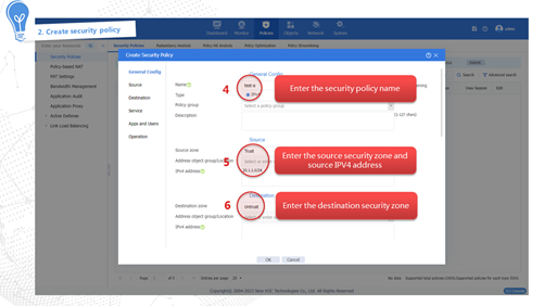
Security policy
As shown in Figure 4, a security policy filters packets based on the specified filtering conditions such as source/destination security zone, source IP/MAC address, destination IP address, service, application, terminal, user, and time period. It processes matched packets according to the pre-set policy action. If a packet does not match any policy, it will be discarded. If no filtering conditions are configured in the security policy, the policy matches all packets.
Figure 4 Packet processing of security policy
Configuring basic firewall settings
Obtaining the factory default settings
Table 1 shows the factory default settings of the device. You can also obtain the default username and password of the device through the nameplate on the device.
Table 1 Factory default settings of the device
|
Item |
Default |
Remarks |
|
Username |
admin |
N/A |
|
Password |
admin |
N/A |
|
Login type |
· Device login from the Web interface · Device login from the console port |
Configure other login types as needed. |
|
IP address of the Ethernet management interface |
· Interface: GigabitEthernet 1/0/0 or M-GigabitEthernet 1/0/0 · IP address: 192.168.0.1/24 |
The management interface varies by device model. For more information, see the product manuals or the nameplate on the device. |
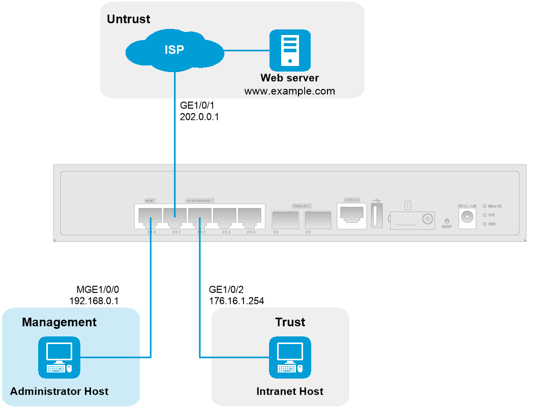
Application scenario-based networking
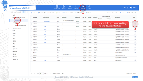
As shown in Figure 5, connect the management interface, internal interface GE 1/0/2, and external interface GE 1/0/1 of the device. The internal interface acts as a LAN port and is typically added to the Trust security zone to connect the intranet host. The external interface acts as a WAN port and is typically added to the Untrust security zone to connect the carrier network for external communication.
To configure the device from the CLI, use the console cable to connect the serial port on the management PC to the console port on the device for first login.
Logging in to the Web interface
Restrictions and guidelines
As a best practice, using the following browsers:
· Chrome 40 and higher
· Firefox 19 and higher.
· Internet Explorer 10 and higher.
To access the Web interface, you must use the following browser settings:
· Accept the first-party cookies (cookies from the site you are accessing).
· Enable active scripting or JavaScript, depending on the Web browser.
· If you are using an Internet Explorer browser, you must enable the following security settings:
¡ Script ActiveX controls marked safe for scripting.
¡ Run ActiveX controls and plug-ins.
· To ensure correct display of webpage contents after software upgrade or downgrade, clear data cached by the browser before you log in.
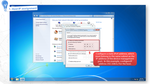
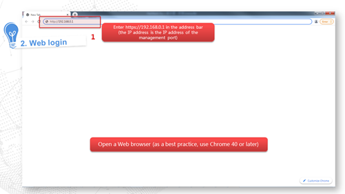
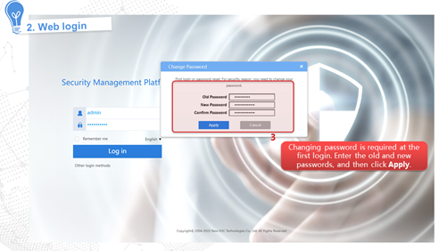
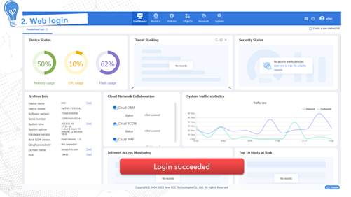
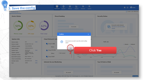
Procedure


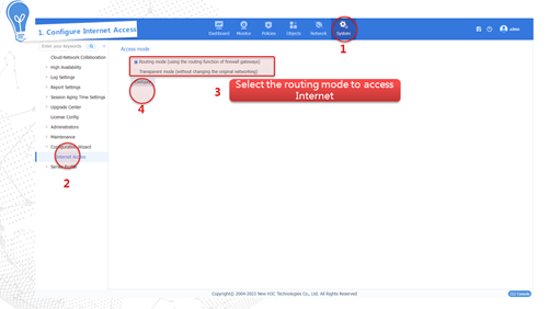
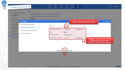
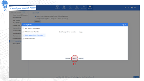
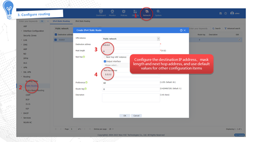
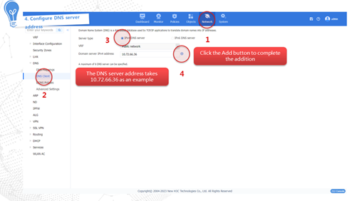
Internet access in routing mode
Internet access in routing mode indicates that the device in the network is deployed in Layer 3 mode. That is, the uplink and downlink service interfaces of the device operate in Layer 3 mode. In this mode, the device typically serves as the gateway of the enterprise that connects the internal network and the Internet, and performs security monitoring and control of network traffic. In this mode, the device supports abundant routing and security features. To adapt to various network environments, the device provides the following methods to fast access the Internet:
· Specified IP address—Obtains a fixed public network IP address from the carrier. Users in the internal network must use this public network IP address to access the Internet.
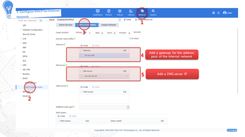
· DHCP—The device dynamically obtains a public network IP address through the DHCP service provided by the carrier to access the Internet.
· PPPoE—The user can access the Internet through a PPPoE access authentication account obtained from the carrier.
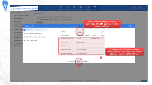
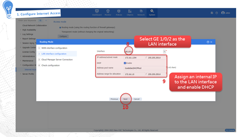
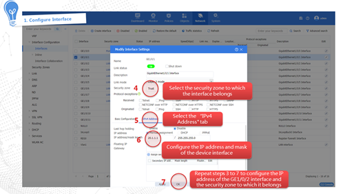
Internet access through a specific IP address
This access method indicates obtaining a fixed public network IP address from the carrier. Users in the internal network must use this public network IP address to access the Internet. The configuration procedure is as follows:


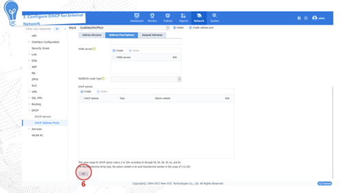
Internet access through DHCP
The device dynamically obtains a public network IP address through the DHCP service provided by the carrier to access the Internet. The configuration procedure is as follows:


Internet access through PPPoE
The user can access the Internet through a PPPoE access authentication account obtained from the carrier. The configuration procedure is as follows:


Internet access in transparent mode
Compared with the routing mode, the transparent mode adopts the Layer 2 mode for deploying the device in the network. That is, the uplink and downlink service interfaces of the device operate in Layer 2 mode. In this mode, the device is typically deployed on the inner side of enterprise gateway. The device is not directly connected to the Internet but is capable of monitoring and controlling network traffic for security purposes. This mode does not require routing or NAT configuration, and can implement fast device deployment and security service onboarding without changing the network structure. The configuration procedure is as follows:


Configuring signature library upgrade
To update a signature library of a service module, you must install the appropriate license. After the license expires, the service module can still use the existing signature library but cannot upgrade the signature library.
The following methods are available for upgrading the signature library for a service module:
· Automatic upgrade—The device automatically downloads the most up-to-date signature file to upgrade its local signature library periodically.
· Online upgrade—The device downloads the most up-to-date signature file to upgrade its local signature library immediately after you trigger the operation.
· Manual upgrade—Use this method when the device cannot obtain the signature file automatically. You must manually download the most up-to-date signature file, and then use the file to upgrade the signature library on the device.
Configuring automatic signature library upgrade


Triggering a signature library upgrade


Performing a manual signature library upgrade

Activating and installing a license for the first time
Some features require a license to run on the device. You must activate and install a license to use such a feature.
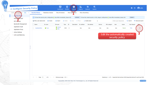
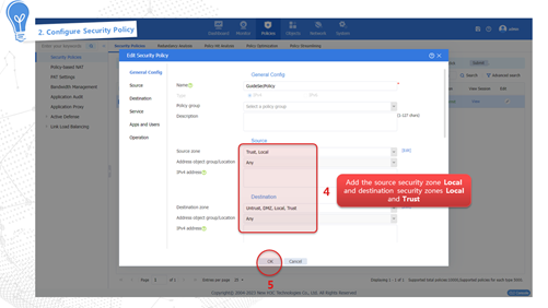
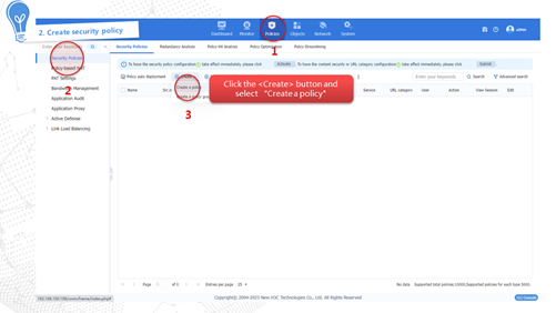
Configuring a security policy

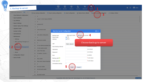
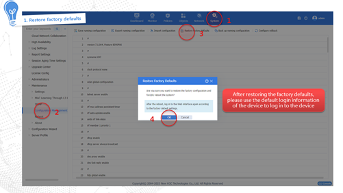
Restoring the factory defaults
|
|
IMPORTANT: Use this feature with caution. This feature delete all configurations and files except .bin files and license files. |

Upgrading software

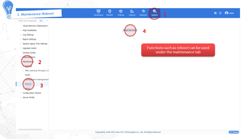
Performing maintenance and diagnostics

Advanced features
NAT
Network Address Translation (NAT) translates an IP address in the IP packet header to another IP address. Typically, NAT is configured on gateways to enable private hosts to access external networks and external hosts to access private network resources such as a Web server.
Use this feature in routing mode. In the initial configuration, the quick wizard in routing mode automatically generates a NAT policy to ensure internal-to-external access. You can directly use the NAT policy, or configure different NAT policies based on the network requirements.
Figure 6 Network diagram for NAT

For more information, see the configuration guide for the product.
Remote office through IPsec
IP Security (IPsec) is defined by the IETF to provide interoperable, high-quality, cryptography-based security for IP communications. It is a Layer 3 VPN technology that transmits data in a secure channel established between two endpoints (such as two security gateways). Such a secure channel is usually called an IPsec tunnel. You can use IPsec for secure access to remote offices.
Figure 7 Network diagram for IPsec

For more information, see the configuration guide for the product.
Remote office through SSL VPN
SSL VPN provides SSL-based secure remote access services through an SSL VPN gateway. Users from anywhere on the Internet can establish a secure connection to an SSL VPN gateway through an SSL-enabled browser to access protected resources behind the gateway.
Figure 8 Network diagram for SSL VPN

For more information, see the configuration guide for the product.
Hot backup
Hot backup is a device-level high availability (HA) solution. It enables two devices to back up each other dynamically to ensure user service continuity upon failure of one of the devices. Hot backup is implemented through H3C proprietary Remote Backup Management (RBM).
Figure 9 Hot backup functionality diagram

For more information, see the configuration guide for the product.