- Released At: 08-01-2024
- Page Views:
- Downloads:
- Table of Contents
- Related Documents
-
H3C Indoor Device Operating Environment Requirements
Copyright © 2023 New H3C Technologies Co., Ltd. All rights reserved.
No part of this manual may be reproduced or transmitted in any form or by any means without prior written consent of New H3C Technologies Co., Ltd.
Except for the trademarks of New H3C Technologies Co., Ltd., any trademarks that may be mentioned in this document are the property of their respective owners.
The information in this document is subject to change without notice.
Contents
1 H3C indoor device operating environment requirements
Operating environment requirements
Corrosive gas concentration limits
Operating lightning protection and grounding requirements
General lightning protection and grounding requirements
Lightning protection and grounding requirements for communication power supplies
Rack lightning protection and grounding requirements
Device lightning protection and grounding requirements
Signal cable grounding requirements
Maintenance endpoint grounding requirements
Device power supply requirements
Dual-route hybrid power supply requirements
Power supply system application principles
Determination basis for power supply system failure
1 H3C indoor device operating environment requirements
This document is not applicable to all countries and regions. Ensure compliance with local indoor device operating environment requirements.
Equipment room requirements
The design of the equipment room must comply with relevant standards and specifications, and meet requirements for location selection, device layout, architectural structure, electrical system, electromagnetic shielding, water supply and drainage, and fire safety.
This section describes the basic design requirements applicable to all types of equipment rooms. For more detailed and specific equipment room design requirements, see the relevant standards and specifications.
Location
Consider a comprehensive range of factors such as power supply and distribution, environment, and transportation when selecting a location for the equipment room. Select a location that meets the environmental design specifications for communication network planning and communication equipment engineering.
Make sure the location of the equipment room meets the following requirements:
· Far from areas with a high risk of natural disasters such as floods and earthquakes.
· Away from areas that generate dust, oil fumes, harmful gases, and places where corrosive, flammable, or explosive substances are produced or stored.
· Distant from strong vibration sources and strong noise sources.
· Away from strong electromagnetic field interference.
Layout
The devices installed in an equipment room mainly incudes communication devices, communication transmission devices, and power supply and other supporting devices. For ease of management and maintenance, arrange these devices compactly and install them in different rooms as required by services.
One critical principle for designing the equipment room layout is to ensure convenient cabling and easy maintenance for communication cables and power cords.
Figure1-1 Equipment room floor layout
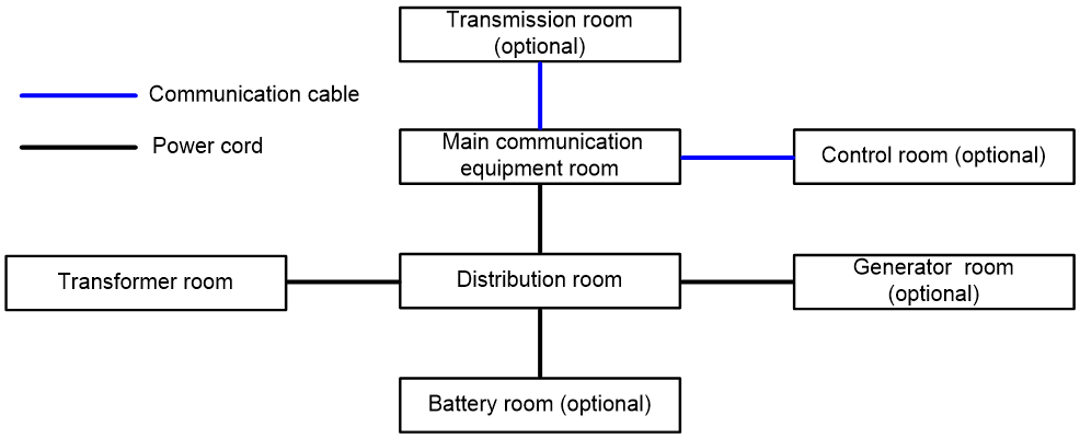
Make sure the equipment room layout meet also the following requirements:
· If the equipment room is equipped with a fault-tolerant system, arrange mutually backup devices in different physical compartments, and lay mutually backup pipelines along different paths.
· Do not place battery packs and generators in the same room as the electronic device cabinets.
Construction
Table1-1 describes the requirements for equipment room construction.
Table1-1 Requirements for equipment room construction
|
Item |
Requirements |
|
Flooring |
Follow these restrictions and guidelines when laying the floor in the equipment room: · Install anti-static active flooring in the equipment room. Use electrostatic conductive floor material instead if anti-static active flooring is not available. · Ground the anti-static active flooring or electrostatic conductive floor material. Connect it to the grounding facility using a current limit resistor and connecting wire. · Ensure that the floor installation is tight and sturdy. · Do not place pathways or drains under the equipment room floor. · Provide dust prevention and insulation underneath the floor when the raised floor acts as an air conditioning static pressure box. · Ensure that the floor load-bearing capacity meets the relevant standards. |
|
Doors and windows |
Ensure doors and windows are sealed with dust-proof rubber strips. As a best practice, install double-glazed windows. |
|
Wall |
Paint the walls with matte finish paint and avoid using materials that can easily powder. |
|
Internal partition |
Separate the device installation area from the equipment room door, and use baffles to isolate some dust. |
|
Air conditioning |
Do not place air conditioning intake vents near drains. |
|
Decorative materials |
Choose materials that are airtight, dust-free, easy to clean, have minimal deformation under temperature and humidity changes, and are environmentally friendly. |
|
Biological requirements |
Make sure no biologics such as fungus, plants, or animals exist in the equipment room. · Take moisture-proof measures. · Apply anti-mold treatments to decorative materials. · Seal any openings in the equipment room, such as cable holes and antenna holes. · Maintain the cleanliness of the equipment room and carry out regular disinfection. |
Electrical system
Distinguish the power connection points of electronic information devices from those of other devices strictly, and clearly mark them.
As a best practice, power an electronic information device with an uninterruptible power supply system. Automatic and manual bypass devices must be present for an uninterruptible power supply system.
As a best practice, distribute power to electronic information devices using a distribution header cabinet or dedicated power distribution busbar. To use a distribution header cabinet, place it near the electrical device. To use a dedicated power bus, ensure its flexibility.
Reserve spare capacity in the power supply system for the scalability of the electronic information system.
Do not lay outdoor power lines overhead.
Make sure the equipment room is equipped with three lighting systems.
· Common lighting system: A lighting system power by the municipal power supply system.
· Backup lighting system: A lighting system powered by backup power sources (such as diesel generators) within a communication office (station).
· Emergency lighting system: A lighting system powered by batteries temporarily when the common lighting power supply is interrupted and the backup power sources are not yet operational.
EMC shielding
A metal shielding structure will increase the overall weight of the electromagnetic shielding room. In an equipment room with an electromagnetic shielding room, calculate the structural load value as the sum of the electronic information device load value and the metal shielding structure load value.
Ground the electromagnetic shielding room using a separate downlead.
Install shielding components such as filters and waveguides on the outside of the metal shell of the electromagnetic shielding room.
Water supply and drainage
Ensure that water supply and drainage pipes unrelated to the equipment room do not pass through it. Also, avoid install water supply and drainage pipes related to the equipment room above electronic information devices. Install valves on the water pipes entering the equipment room.
Take leakage and condensation prevention measures for water supply and drainage pipes.
When the equipment room has a floor drain, use a clean room-specific floor drain or a self-closing floor drain. Install water seal facilities below the floor drain and take measures to prevent water seal damage and backflow.
For rooms equipped with automatic sprinkler fire extinguishing facilities, air conditioners, and humidifiers, install water barriers and drainage facilities on the floor.
Do not place fire hydrants inside the equipment room. Instead, place them in clearly visible and easily accessible locations near the staircase or corridor.
Fire safety
Equip the equipment room with fixed or portable fire extinguishing equipment in accordance with relevant fire safety regulations and standards, and determine the quantity and placement of fire extinguishers.
Install an automatic fire alarm system in the equipment room. Keep corridors and stairways unobstructed and clearly mark evacuation signs.
In places where a gas extinguishing system is installed, provide dedicated air respirators or oxygen respirators.
The evacuation door of the equipment room should open in the evacuation direction and can close automatically. Ensure that it can be opened from inside the equipment room under any circumstances.
Seismic fortification
Ensure that the seismic fortification level of the equipment room building is one level higher than the local basic construction seismic fortification level. For equipment room buildings that do not meet the seismic fortification requirements, perform seismic reinforcement.
Lightning protection
If isolated elevated structures such as chimneys, water towers, and antennas on the top of the equipment room building have a height of 15 m (49.21 ft) or above, design them in accordance with building lightning protection requirements.
The lightning protection design must include measures to prevent intrusion of direct and induced lightning strike currents. Figure1-2 is an example of lightning protection and grounding diagram of a building with measures to prevent intrusion of direct lightning strike currents.
Figure1-2 Building lightning protection and grounding diagram
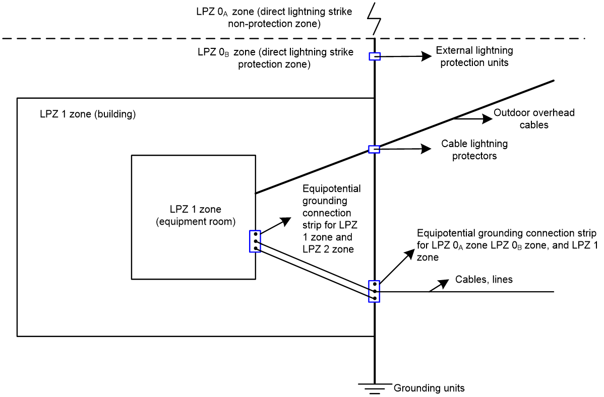
To prevent lightning current intrusion, take the following measures:
· Install lightning protection mesh (strips), lightning rods, or lightning arresters composed of both in areas of buildings susceptible to lightning strikes, along the height of the buildings. To prevent direct lightning strikes, install overhead lightning protection wires or lightning rods on the tops of objects protruding from the roof (such as chimneys and antennas). To prevent induced lightning strikes, connect metal objects such as railings, doors, and windows on the exterior walls of the building to lightning protection devices.
· Follow these restrictions and guidelines when installing a downlead conductor:
¡ Use metal such as copper and steel. Make sure the sectional area is not smaller than 50 mm2 (0.08 in2).
¡ Make sure the grounding resistance does not exceed 10 Ω.
¡ Establish electrical connectivity to balance the potential within the building.
¡ Ensure that measures are in place to prevent mechanical damage, ensure insulation, and resist corrosion.
· Ground the outdoor metal pipes and cables before they enter the building. When overhead outdoor cables are directly led into the room, install a lightning protection device at the entrance.
· As a best practice, use a combined grounding method for the lightning protection grounding of the buildings. Combined grounding refers to connecting the grounding bodies of various buildings within the communication office (station) to form a common grounding network. Also, it incorporate the operation grounding, protective grounding, logic grounding, shielding body grounding, anti-static grounding, and building lightning protection grounding of electronic devices into the same grounding system.
Operating environment requirements
Temperature and humidity
Adverse temperature and humidity conditions in the equipment room will accelerate the aging of devices and reduce the capability of the device to withstand harsh environment conditions.
· Lasting high relative humidity can cause poor insulation, electricity leakage, mechanical property change of materials, and metal corrosion.
· Lasting low relative humidity can cause washer contraction and ESD and bring issues including loose screws and circuit failure.
· High temperature can accelerate aging of insulation materials and significantly lower the reliability and lifespan of the router.
· Lasting high temperature and relative humidity can aggravate corrosion of corrosive gas and particles to the bare parts of the device and significantly reduce the service life of the device.
To prevent the preceding issues, maintain favorable temperature and humidity conditions in the equipment room. As a best practice, make sure the temperature and humidity conditions in the equipment room meet the requirements of American Society of Heating, Refrigerating and Air-Conditioning Engineers (ASHRAE) for equipment room environments as described in Table1-2.
Table1-2 Temperature and humidity requirements
|
Item |
Requirement |
|
Temperature |
18°C to 27°C (64.4°F to 80.6°F) |
|
Relative humidity |
< 60% RH |
|
Dew point temperature |
5.5°C to 15°C (41.9°F to 59°F) |
The temperature and humidity requirements vary by device model. For information about the requirements, see the installation guide for the device.
Corrosive gas concentration limits
Corrosive gases can accelerate corrosion and aging of metal components and even cause device failure. Table1-3 describes common corrosive gases and their sources.
Table1-3 Common corrosive gases and their sources
|
Corrosive gas |
Sources |
|
Hydrogen sulfide (H2S) |
Geothermal emissions, microbiological activities, petroleum manufacturing, wood corrosion, and sewage treatment. |
|
Sulfur dioxide (SO2) and sulfur trioxide (SO3) |
Coal combustion, petroleum products, automobile exhaust, ores smelting, sulfuric acid manufacturing, and tobacco combustion. |
|
Sulphur (S) |
Foundry workshop and sulfur manufacturing. |
|
Hydrogen Fluoride (HF) |
Fertilizer manufacturing, aluminum manufacturing, ceramics manufacturing, iron and steel manufacturing, electronic equipment manufacturing, and mineral combustion. |
|
Nitrogen Oxide (NOx) |
Automobile exhaust, petroleum combustion, microbial activities, and chemical industry. |
|
Ammonia (NH3) |
Microbial activities, sewage, fertilizer manufacturing, and geothermal emissions. |
|
Carbonic Monoxide (CO) |
Combustion, automobile exhaust, microbial activities, and wood rotting. |
|
Chlorine (Cl2) and chlorine dioxide (ClO2) |
Chlorine manufacturing, aluminum manufacturing, zinc manufacturing, and waste decomposition. |
|
Hydrochloric acid (HCl) |
Automobile exhaust, combustion, forest fires, and combustion of oceanic process polymers |
|
Hydrobromic acid (HBr) and hydroiodic acid (HI) |
Automobile exhaust |
|
Ozone (O3) |
Atmospheric photochemical processes (mostly including nitrogen monoxide and perhydrogen compounds) |
|
Alkanes (CnHn) |
Automobile exhaust, tobacco combustion, animal excrement, sewage, and wood rotting. |
Corrosive gas concentration limits vary by device model. For information about the requirements, see the installation guide for the device.
Corrosive gas concentration limits for the data center equipment room
As a best practice, make sure the corrosive gas concentration in a data center equipment room meets the requirements of severity level G1 of ANSI/ISA 71.04-1985. The rate of copper corrosion product thickness growth must be less than 300 Å/month, and the rate of silver corrosion product thickness growth must be less than 200 Å/month. Angstrom (Å) is a metric unit of length equal to one ten-billionth of a meter.
To meet the copper and silver corrosion rates stated in severity level G1, make sure the corrosive gases in the equipment room do not exceed the concentration limits as shown in Table1-4.
Table1-4 Corrosive gas concentration limits in the data center equipment room
|
Corrosive gas |
Concentration (ppb) |
Remarks |
|
H2S |
<3 |
The concentration limits are calculated based on the reaction results of the gases in the equipment room with a relative humidity less than 50%. If the relative humidity of the equipment room increases by 10%, the severity level of ANSI/ISA 71.04-1985 to be meet must also increase by 1. |
|
SO2, SO3 |
<10 |
|
|
Cl2 |
<1 |
|
|
NOx |
<50 |
|
|
HF |
<1 |
|
|
NH3 |
<500 |
|
|
O3 |
<2 |
|
|
NOTE: Part per billion (ppb) is a concentration unit. 1 ppb represents a volume-to-volume ratio of 1 to 100000000. |
Corrosive gas concentration limits for the non-data center equipment room
The corrosive gas concentration for the non-data center equipment room must meet the requirements of class 3C2 of IEC 60721-3-3:2002, as shown in Table1-5.
Table1-5 Corrosive gas concentration limits in the non-data center equipment room
|
Gas |
Average concentration (mg/m3) |
Maximum concentration (mg/m3) |
|
SO2 |
0.3 |
1.0 |
|
H2S |
0.1 |
0.5 |
|
Cl2 |
0.1 |
0.3 |
|
HCI |
0.1 |
0.5 |
|
HF |
0.01 |
0.03 |
|
NH3 |
1.0 |
3.0 |
|
O3 |
0.05 |
0.1 |
|
NOX |
0.5 |
1.0 |
|
|
CAUTION: As a best practice, control the corrosive gas concentrations in the equipment room at their average values. Make sure the corrosive gas concentrations do not exceed 30 minutes per day at their maximum values. |
Guidelines for controlling corrosive gases
To control corrosive gases, follow these guidelines:
· As a best practice, do not build the equipment room in a place with a high concentration of corrosive gases.
· Make sure the equipment room is not connected to sewer, sewage, vertical shaft, or septic tank pipelines and keep it far away from these pipelines. The air inlet of the equipment room must be away from such pollution sources.
· Use environmentally friendly materials to decorate the equipment room. Avoid using organic materials that contains harmful gases, such as sulfur or chlorine-containing insulation cottons, rubber mats, sound-proof cottons, and avoid using plasterboards with high sulfur concentration.
· Place fuel (diesel or gasoline) engines separately. Do not place them in the same equipment room with the device. Make sure the exhausted air of the engines will not flow into the equipment room or towards the air inlet of the air conditioners.
· Place batteries separately. Do not place them in the same room with the device.
· Employ a professional company to monitor and control corrosive gases in the equipment room regularly.
Cleanliness
Mechanically active substances buildup on the chassis might result in electrostatic adsorption, which causes poor contact of metal components and contact points. In the worst case, electrostatic adsorption can cause communication failure.
Dust particle concentration limits vary by device model. For information about the requirements, see the installation guide for the device.
Requirements for the data center equipment room
The concentration of dust participles in the equipment room must meet the ISO 14644-1 Class 8 cleanliness requirements, as described in Table1-6. Make sure no zinc whiskers are in the equipment room.
Table1-6 Dust particle concentration limit in the equipment room
|
Particle diameter |
Concentration limit |
|
≥ 5 µm |
≤ 29300 particles/m3 |
|
≥ 1 µm |
≤ 832000 particles/m3 |
|
≥ 0.5 µm |
≤ 3520000 particles/m3 |
Requirements for the non-data center equipment room
The concentration of dust participles (particle diameter ≥ 0.5 µm) must meet the requirement of the GB 50174-2017 standard, which is less than 17600000 particles/m3.
Guidelines for controlling cleanliness
To maintain cleanliness in the equipment room, follow these guidelines:
· Keep the equipment room away from pollution sources and do not smoke or eat in the equipment room.
· Use double-layer glass in windows and seal doors and windows with dust-proof rubber strips.
· Use dustproof materials for floors, walls, and ceilings and use matt coating that does not produce powders.
· Keep the equipment room clean and clean the air filters of the rack regularly.
· Wear ESD clothing and shoe covers before entering the equipment room. Keep the ESD clothing and shoe covers clean and replace them frequently.
EMI prevention
All electromagnetic interference (EMI) sources, from outside or inside of the device and application system, adversely affect the router in the following ways:
· A conduction pattern of capacitance coupling.
· Inductance coupling.
· Electromagnetic wave radiation.
· Common impedance (including the grounding system) coupling.
· Conduction of wires (power wires, signal wires, and output wires)
The environment where the device operates must meet the EMI prevention requirements as described in Table1-7.
Table1-7 EMI prevention requirements
|
EMI parameter |
Requirement |
|
|
Amplitude modulated RF field immunity |
Frequency (MHz) |
80 MHz to 6000 MHz |
|
Ampl, V/m (rms) |
3 |
|
|
Power frequency magnetic field immunity |
Ampl, A/m |
3 |
To prevent EMI, use the following guidelines:
· Keep the device far away from high-power radio transmission stations, radar transmission stations, high-voltage power transmission lines, transformers, and high-frequency high-current devices.
· Make sure the AC power supply system is a TN system, which is also called a neutral grounding protection system that connects the metal casing of the electrical device and the normally uncharged metal parts to the working neutral line. Use a single-phase three-wire power socket with a protective grounding wire (PE wire) for each AC power outlet to effectively filter out power grid interference from the device's filter circuit.
· Use electromagnetic shielding, for example, shielded interface cables, when necessary.
· To prevent signal ports from getting damaged by overvoltage or overcurrent caused by lightning strikes, route interface cables only indoors. If you have to route cables outdoors, install a lightning arrester for each network port.
ESD prevention
To prevent electrostatic damage, follow these guidelines:
· Ensure that all operators have completed ESD prevention training.
· Ensure that dust and temperature and humidity conditions in the equipment room meet installation requirements.
· Ensure that the personnel in the operating area wear antistatic clothing and static dissipative shoes, and wear anti-static wristbands or gloves and use anti-static tools when operating the device.
· Clear any static-producing materials (including ordinary plastic bags, ordinary foam materials, ordinary plastic products, and transparent tape) from the operating site and personal, keeping them at least 1 m (33.8 ft) away from the cabinets and equipment.
· Ground all conductors in the equipment room reliably:
¡ Ground all test instruments and electric tools to use reliably.
¡ Ground cabinets and devices reliably, and ground the anti-static wristbands and gloves reliably.
· When operating removable components, take the following measures to prevent electrostatic discharge:
¡ Before unpacking a removable component, clean the equipment room environment to prevent electrically charged dust particles from damaging the component. Unpackaged removable components must be installed on the device immediately.
¡ Use a dedicated anti-static brush to clean the dust on the card. Do not use plastic brushes or other non-anti-static materials to clean the card and sensitive components.
¡ Hold the external metal shield of the removable component during operation. Avoid direct contact of human hands, metal tools, or other objects with the external interfaces, cores, components, and PCB of the removable component.
¡ Place removed removable components on an anti-static workbench or put them into anti-static bags.
Operating lightning protection and grounding requirements
General lightning protection and grounding requirements
All the grounding facilities share a group of grounding conductors. Design the grounding system based on the principles of voltage balance and equal potential.
Establish an equipotential bonding network in the equipment room. The metal covers of electrical and electronic devices, cable management brackets in the equipment room, cable trays, racks, chassis, metal ventilation pipes, metal doors and windows, safety protection grounding, and other normally uncharged metal components must be connected to the network with the shortest distance.
General requirements for grounding cables are as follows:
· Grounding cable must be copper cables in order to reduce the high-frequency impedance. Make sure grounding cables are as thick and short as possible. To ensure reliable electrical contact when you connect grounding cables, weld or crimp copper grounding cables and weld steel grounding cables.
· Ensure good electrical contact at the connection points at both ends of a grounding cable. Do not ground the device through other devices, for example, do not add a switch or fuse to a grounding cable.
· Each grounding cable led from the collective grounding cable must be clearly marked.
· Do not use a neutral cable as a grounding cable for an AC device. The rack and the device grounding cable must be insulated from the neutral wire of an AC power supply.
· Use a yellow-green insulated copper grounding cable as a device grounding cable. Bind the cable securely and neatly and never bend the cable. Affix a clear label to the cable.
|
|
NOTE: The grounding cable color varies by country or region. Select a compliant grounding cable as needed. |
General requirements for device grounding connection are as follows:
· Before grounding connection, make sure the joint face is clean.
· Use surface contact for connection and make sure the connection area meets the current requirements.
· Make sure the joint face has good conductivity.
· As a best practice to prevent electrochemical corrosion, use connection components made of the same metal.
· Make sure the connection components are connected reliably. Treat the joint with anti-loosening and anti-corrosion measures.
Lightning protection and grounding requirements for communication power supplies
The grounding cables of power supplies in the power room of a comprehensive communication building with centralized power supply must be led from the collective grounding cable.
Lightning protection grounding must share the same grounding equipment with AC working grounding, DC working grounding, and safety protection grounding. The grounding resistance of the grounding equipment must be determined by the minimum grounding resistance required by the connected devices.
The working grounding and protection grounding of a communication power supply shares the same group of grounding conductors with the communication device protection grounding. A communication power supply shares the same protection grounding strip with communication devices.
If the equipment room provides only one protection grounding strip, connect both the protection and working grounding cables to the grounding strip. If the equipment room provides two grounding strips (protection and working grounding strips), connect the protection and working grounding cables of the communication power supply to the protection and working grounding strips, respectively. The two grounding strips must share a group of grounding conductors.
When interference occurs between different communication systems or devices because of the grounding method, prepare a busbar for each communication system or device. The grounding cable of each communication system or device is first connected to its own busbar, and then led to the floor busbar (or collective cable) for grounding.
Rack lightning protection and grounding requirements
If the front, rear, or side door of the rack has a grounding terminal and grounding sign, use grounding cables to connect both the grounding terminals on the door and rack body to a grounding strip to achieve equipotential bonding.
If the chassis and the distribution box each has a grounding terminal and grounding sign, use grounding cables to connect the grounding terminals on the chassis, distribution box, and rack body to a grounding strip to achieve equipotential bonding.
The distribution frame, metal brackets, and rack of the device must be grounded and achieve equipotential bonding.
Establish an equipotential bonding network in the equipment room. The device metal covers, chassis, rack, cabinet, metal pipes, metal cable trays, metal sheath of shielded cables, antistatic grounding of information devices, safety protection grounding, and surge arrester grounding terminals must be connected to the equipotential bonding network with the shortest distance.
Device lightning protection and grounding requirements
All communication devices and supporting devices (such as mobile base stations and power supplies) in an equipment room must be grounded. The protection grounding cables of all devices in a telecommunication bureau (station) must be finally connected to the same main grounding strip.
Connect the grounding cables of devices in the same row in an equipment room to the grounding strip of the head rack in the row. Connect the grounding strip of each head rack to the main grounding strip of the equipment room.
Figure1-3 Main grounding terminal on a rack
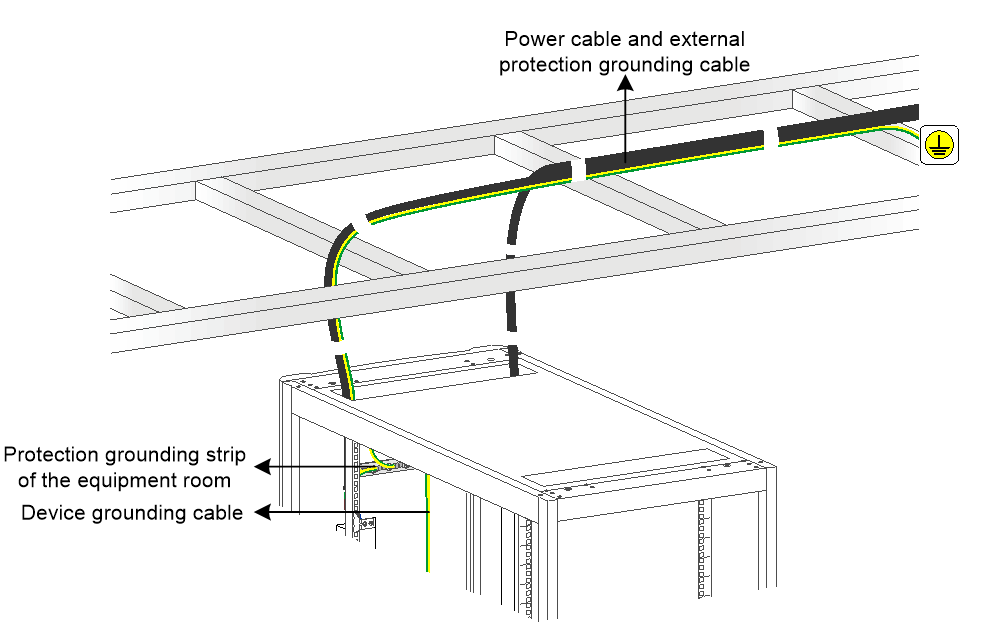
Connect the –48 V and RTN wires led from a device power input terminal to the –48 V and RTN busbars of the power supply cabinet or distribution cabinet (or head rack in a row) in the equipment room.
Connect the PGND grounding cable led from the main grounding terminal on the rack to a protection grounding strip as follows:
· When communication devices are powered by a distribution cabinet, connect the PGND grounding cable to the protection grounding trip of the equipment room or distribution cabinet.
· When communication devices are powered by a power supply cabinet, connect the PGND grounding cable to the protection grounding trip of the equipment room or power supply cabinet.
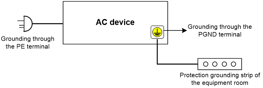
As shown in Figure1-4, to ground an AC device, you can use either of the following methods:
· Connect the AC device to the protection grounding strip of the equipment room.
· Connect the PE wire of the three-core AC power cord to the protection earthing terminal of the AC power grid reliably.
After you ground the AC device, use a multimeter to verify the electrical continuity and reliability of device grounding.
Figure1-4 Grounding an AC device
Devices on the same rack must be equipotentially bonded. Then, use a multimeter to verify the grounding electrical continuity and reliability of each equipotential bonding point.
Signal cable grounding requirements
As a best practice, use shielded cables or cables with metal sheath or metal pipes as signal cables led into and out of a telecommunication bureau (station). The shielding layer, metal sheath, or metal pipe of an incoming cable must be connected to the grounding strip of the equipment room at the location where it enters the equipment room.
The shielding layer and external shield of a shielded cable must be grounded at both ends. Make sure both ends of the shielding layer have good electrical contact with the outer surface of the device metal chassis.
Ground idle signal cables led into and out of a telecommunication bureau (station) in the equipment room.
Ground the reinforcing metal stiffeners of a fiber cable led into and out of a telecommunication bureau (station) on an optical distribution frame (ODF) or fiber splice enclosure after the fiber cable enters the equipment room.
A digital distribution frame (DDF) or ODF must be grounded. When the DDF or ODF and communication devices reside in the same equipment room, they must share an equipment room grounding strip.
All metal connectors and reinforcing metal stiffeners of optical fibers must be directly grounded at the entrance.
Ground the shielding layer at the top, middle, and bottom of the base station feeder routed from the center of the tower.
Equip the equipment room feeder window with a grounding strip for the feeder and directly connect the grounding strip to the earthing grid. Ground the feeder at the feeder window before it enters the equipment room through a cable tray.
When the height of a tower is greater than or equal to 60 m (196.85 ft), additionally ground the metal shielding layer of the feeder in the middle of the tower.
Cable routing requirements
When you route protection grounding cables, make sure the following requirements are met:
· Route grounding cables indoor or bury them in the earth. Do not route a grounding cable from outdoor or from near the tower foot.
· Route and bind grounding cables and signal cables separately. For parallel cabling, make sure the space between cables is not less than 50 mm (1.97 in).
· The routed grounding cables must be as short, straight, and neat as possible. Cut off any excess cables and do not coil the grounding cables. When you bend a cable, make sure the bend radius is greater than 10 times the diameter of the conductor.
· As a best practice, make sure the grounding cables of communication devices in an equipment room are not longer than 30 m (98.43 ft). If a grounding cable exceeds 30 m (98.43 ft), arrange a grounding strip nearly.
When you route power cables, make sure the following requirements are met:
· Route and bind power cables led into and out of a telecommunication bureau (station) and signal cables and power cords routed indoor separately. When you route power cables in parallel, follow these guidelines:
¡ If the power capacity of power cables is less than 5 kVA, make sure the space between cables is not less than 30 cm (11.81 in).
¡ If the power capacity of power cables is greater than 5 kVA, make sure the space between cables is not less than 60 cm (23.62 in).
· Do not lead a power cable into a telecommunication bureau (station) overhead. After the power cable is led into the equipment room building, install a lightning arrestor that is compliant with national and industry standards for it. Ground the lightning arrestor nearby and make sure the grounding cable of the lightning arrestor is as short as possible.
When you route signal cables, make sure the following requirements are met:
· Route and bind signal cables led into and out of a telecommunication bureau (station) and signal cables and power cords routed indoor separately. For parallel cabling, make sure the space between cables is not less than 50 mm (1.97 in).
· Do not lead a signal cable into a telecommunication bureau (station) overhead. After the signal cable is led into the equipment room building, install a signal lightning arrestor for it. Make sure the grounding cable of the signal lightning arrestor is as short as possible.
· Install and bundle outdoor and indoor signal cables separately and route them from different outlets on the rack.
Maintenance endpoint grounding requirements
When a maintenance endpoint uses AC power supply, make sure the PE wire of the power plug for each office computer is reliably connected. For important and previously lightning-damaged office computers, install integrated power and network protection power strips. After installation, use a multimeter to verify the electrical continuity and reliability between the maintenance endpoint and the PE end of the AC power supply.
When a maintenance endpoint is powered by a UPS or inverter, the UPS or inverter chassis is directly connected to either of the following locations:
· Grounding strip in the distribution cabinet or head rack in a row that supplies power for the connected communication device.
· Grounding strip of the equipment room.
You can directly ground the maintenance endpoint through the PE wire in the three-core AC power cable of the UPS or inverter.
When a maintenance endpoint (including a computer) uses DC power supply, use a grounding cable to reliably connect the maintenance endpoint chassis to one of the following locations:
· Grounding terminal on the connected communication device.
· Grounding strip of the equipment room.
· Grounding strip in the distribution cabinet or head rack in a row that supplies power for the connected communication device.
Device power supply requirements
AC power supply requirements
An AC power supply system consists of the transformation and distribution system, backup power supply system, UPS, and corresponding AC distribution.
Under the condition of satisfying the telecommunication bureau (station) load, an AC power supply system must meet the following requirements:
· Stable system operation.
· Simple cable routing.
· Safe and convenient operation.
· Convenient maintenance.
An AC power supply system uses three-phase four-wire connection.
Table1-8 shows the nominal voltage and nominal frequency for AC power supplies.
Table1-8 Nominal voltage and nominal frequency for AC power supplies
|
Nominal voltage |
Nominal frequency |
|
110 V |
60 Hz |
|
220 V, 380 V |
50 Hz |
Typically, a UPS is used as the AC backup power source. The AC backup power source and utility power must maintain the same phase. To avoid device restart failure, make sure the switching time between a UPS and utility power is less than 10 milliseconds.
For devices that use AC power, make sure the power supply voltage meets the following requirements:
· For communication devices, power supplies, and building electrical devices, the voltage range measured at the power input terminal is –15% to +10% of the rated voltage.
· The frequency value range of AC power supplies is ±4% of the rated value. The sinusoidal distortion rate of voltage waveform must be less than or equal to 5%.
When you use AC power supply, follow these restrictions and guidelines:
· When the power supply voltage of the utility power cannot meet the regulation or electrical devices have higher requirements, you can use a voltage regulating or stabilization device.
· Important loads must use a dual-bus UPS system. Ordinary loads use N+1 UPSs in parallel for redundancy. Take the impact of harmonics on the generator set for telecommunication bureaus (stations) with large UPS loads.
· An outdoor unified UPS that supplies power for endpoints (such as neighborhood access network devices and mobile communication repeater stations) can work in standalone mode.
DC power supply requirements
A DC power supply system consists of the input distribution, rectifier, battery group, DC output distribution, and DC-DC conversion device.
DC power supply provides float charging for the battery group. When an AC power supply operates correctly, AC passes through a rectifier and works in parallel with the battery group to supply power for communication devices. When a power outage occurs on the AC power supply, the battery group discharges and supplies power for the communication devices. After the AC power supply is restored, use constant voltage and limited current charging with load.
DC power supply of a telecommunication bureau (station) must be stable and reliable. Make sure the power supplies are arranged near the communication devices to shorten the length of DC feeders as much as possible. This reduces energy consumption and installation costs. Deployment of the power supply system and power supplies must be flexible and conducive to device installation and maintenance when more devices are installed in the telecommunication bureau (station).
You can set up multiple independent DC power supply systems for a telecommunication bureau (station).
Table1-9 shows the value range of nominal voltage for DC power supplies in a telecommunication bureau (station).
Table1-9 Value range of nominal voltage for DC power supplies
|
Nominal voltage |
Adjustable range of system output voltage |
Powered terminal voltage range |
|
–48 V |
–43.2 V to –57.6 V |
–40 V to –57 V |
|
240 V (HVDC) |
200 V to 288 V |
192 V to 288 V |
|
336 V (HVDC) |
280 V to 400 V |
260 V to 400 V |
The noise voltage measured at the output terminal of a –48V DC power supply (first level) must meet the requirements of the YD/T 1058 standard. The noise voltage measured at the output terminal of a 240V DC power supply (first level) must meet the requirements of the YD/T 2378 standard. The noise voltage measured at the output terminal of a 336V DC power supply (first level) must meet the requirements of the YD/T 3089 standard.
Telecommunication bureaus (stations) preferably use 240V and 336V HVDC power supplies. –48V DC power supplies are gradually replaced by 240V and 336V HVDC power supplies.
ICT devices on the communication network side can use dual-route hybrid power supply that contain both AC and 240V or 336V HVDC power supplies.
Dual-route hybrid power supply requirements
The telecommunication bureau (station) power system can use a dual-route hybrid power supply architecture that uses both utility power and guaranteed power source.
Figure1-5 Dual-route hybrid power supply architecture
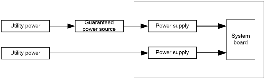
You can use a 240V or 336V DC power supply system or AC UPS power supply system as the guaranteed power source.
Dual-route hybrid power supply can work in load balancing mode or primary/backup mode.
· Load balancing mode—The utility power and the guaranteed power source share loads equally or proportionally.
· Primary/backup mode—The utility power bears all loads and the guaranteed power source works in hot standby state. In this mode, ensure uninterrupted switchover between the guaranteed power source and utility power at rated load.
Power supply system application principles
Equipment room division depends on the specifications and standards. Power supply system application for different equipment rooms must abide by the corresponding national and industry specifications and standards. This section uses the YD/T 1051 standard as an example.
Telecommunication bureaus or stations (equipment rooms) can be divided into the following classes based on the importance and scale:
· Class 1—Telecommunication bureaus (stations) that have equipment rooms carrying international, inter-provincial, and other network-wide services, equipment rooms centrally providing services and support for the entire province, and ultra-large and large data center equipment rooms.
· Class 2—Telecommunication bureaus (stations) that have equipment rooms carrying local network services, equipment rooms centrally providing services and support for the entire local network, and medium-sized data center equipment rooms.
· Class 3—Telecommunication bureaus (stations) that have equipment rooms carrying regional services and provide support within the local network and small-sized data center equipment rooms.
· Class 4—Telecommunication bureaus (stations) that have equipment rooms and base stations carrying network endpoint access services.
The power supply system application principles vary by telecommunication bureau (station):
· Class 1 and 2 telecommunication bureaus (stations) use a power supply method where the transformation and distribution system and backup power supply system are relatively centralized, and the UPS system and DC power supply system are relatively dispersed.
· When the load of Class 3 telecommunication bureaus (stations) is low, the UPS system and DC power supply system can be used for centralized power supply.
· Class 4 telecommunication bureaus (stations) can introduce a reliable 380V or 220V AC power source nearby.
· As a best practice to install multiple transformers in a telecommunication bureau (station), use a power supply method that has the following configuration:
¡ High voltage systems are relatively centralized.
¡ Transformers and low voltage distribution are relatively dispersed.
¡ Power supplies are close to loads.
When a communication bureau (station) uses capacitors for reactive power compensation, make sure the following requirements are met:
· Typically, the communication bureau (station) connects a certain proportion of reactors in series based on the load nature. When the capacitive reactive power is too large, use reactors in parallel for power compensation.
· When the natural power factor of the communication bureau (station) exceeds 0.95, do not use capacitors for reactive power compensation.
· When the communication bureau (station) might have capacitive reactive power, use an active reactive power compensation device.
When the total harmonic distortion (THDi) of the transformation and distribution system exceeds 10%, you must take measures to resolve the issue.
Wiring of a low-voltage AC power supply system must be simple and reliable. Make sure there are no more than three distribution levels from the transformer output end to the power supply systems such as UPS and DC systems, or the air conditioning in the equipment room. Set the parameters of distribution switches at each level based on load. Make sure the upper- and lower-level switches are selective. As the communication load expands, adjust the switch trip setting values as required.
Determination basis for power supply system failure
If the main technical performance of the power supply device or system does not meet the requirements, which affects normal operation, the device or system is determined to be faulty.
The main determination bases for power supply device failure are as follows:
· Rectifier—Rated current output failure, out-of-range voltage, high noise voltage, lower regulated voltage precision than the specified value, alarms that affect the operation or safety of the device and system, and abnormal protection performance.
· UPS—Rated current output failure, out-of-range voltage, lower regulated voltage precision than the specified value, alarms that affect the operation or safety of the device and system, and abnormal protection performance.
· Distribution device—Rated current output failure, out-of-range voltage drop, malfunction, alarms that affect the operation or safety of the device and system, and abnormal protection performance.
· Generator set—Three startup failures, rated current output failure, out-of-range voltage or frequency, leakage (water, oil, gas, or current), and abnormal automatic function of automated generator sets.
· Battery group—Batteries of poor performance, shortcircuit, leakage, deformation, fire, and explosion.
The main determination bases for power supply system failure are as follows:
· DC power supply system—Rated current output failure, out-of-range voltage, and higher noise voltage than the allowed value.
· AC power supply system—Out-of-range voltage or frequency.
References
· YD/T 1821-2018 The Environmental Condition Requirements and Testing Methods of Telecommunication Stations Rooms.
· YD/T 1051-2018 General Requirements of Power Supply System for Telecommunication Stations/Sites.
· YD/T 731-2018 48V Rectifier for Telecommunications.
· YD/T 1058-2015 High Frequency Switch-mode Power Supply for Communications.
· YD/T 2378-2020 240V Direct Current Power Supply System for Telecommunications.
· YD/T 3089-2016 336V Direct Current Power Supply System for Telecommunication.
· ANSI/ISA-71.04-2013 Environmental Conditions for Process Measurement and Control Systems: Airborne Contaminants.
· ISA–71.04–2013 Environmental Conditions for Process Measurement and Control Systems Airborne Contaminants.
· ASHRAE 2011 Gaseous and Particulate Contamination Guidelines For Data Centers.
· ISO 14644-1 Cleanrooms and associated controlled environments – Part 1: Classification of air cleanliness.
· IEC 60721-3-3 Classification of environmental conditions - Part 3-3 Classification of groups of environmental parameters and their severities - Stationary use at weather protected locations.
· IEC 62305-1 Protection against lightning –Part 1: General principles.
· IEC 62305-2 Protection against lightning –Part 2: Risk management.
· IEC 62305-3 Protection against lightning –Part 3: Physical damage to structures and life hazard.
· IEC 62305-4 Protection against lightning –Part 4: Electrical and electronic systems within structures.
· ETSI EN 300 253 Environmental Engineering (EE);Earthing and bonding of ICT equipment powered by -48 VDC in telecom and data centres.
· IEC 60364-5-54 Low-voltage electrical installations –Part 5-54: Selection and erection of electrical equipment – Earthingarrangements and protective conductors.
· ITU-T K.27 Bonding configurations and earthing inside a telecommunication building.
