- Released At: 19-01-2024
- Page Views:
- Downloads:
- Table of Contents
- Related Documents
-
|
|
|
H3C Servers |
|
NVMe Drive Online Replacement User Guide |
|
|
Version: 6W102-20240109
Copyright © 2024 New H3C Technologies Co., Ltd. All rights reserved.
No part of this manual may be reproduced or transmitted in any form or by any means without prior written consent of New H3C Technologies Co., Ltd.
Except for the trademarks of New H3C Technologies Co., Ltd., any trademarks that may be mentioned in this document are the property of their respective owners.
The information in this document is subject to change without notice.
BIOS and HDM software requirements
Identifying the replacement method
Hot swapping of an NVMe drive (for Intel platform servers)
Performing hot removal in Windows
Performing hot removal in Linux (VMD in Auto/Enabled state)
Performing hot removal in Linux (VMD in Disabled state)
Performing hot removal in VMware
Performing hot insertion in Windows
Performing hot insertion in Linux
Performing hot insertion in VMware
Hot swapping of an NVMe drive NVMe (for AMD/Hygon platform servers)
Performing hot removal in Windows
Performing hot removal in Linux
Performing hot insertion in Windows
Performing hot insertion in Linux
Managed hot swapping of an NVMe drive
Performing managed hot removal
Performing managed hot removal in Windows (VMD in Auto/Enabled state)
Performing managed hot removal in Windows (VMD in Disabled state)
Performing managed hot removal in Linux (VMD in Auto/Enabled state)
Performing managed hot removal in Linux (VMD in Disabled state)
Performing hot insertion in Windows (VMD in Auto/Enabled state)
Performing hot insertion in Windows (VMD in Disabled state)
Performing hot insertion in Linux
Configurations with VMD Enabled
Enabling managed hot swapping and hot swapping of NVMe drives
Operating mode of the new drive
Viewing the RAID rebuild status in Windows
Viewing the RAID rebuild status in Linux
About NVMe drives
H3C servers support the following types of NVMe drives: NVMe U.2 SSD, NVMe M.2 SSD, and PCIe accelerator module. This document describes online replacement of NVMe U.2 SSDs (hereinafter referred to as NVMe drives) because the other two types do not support online replacement.
NVMe drives support the following online replacement methods:
· Hot swapping—Allows users to directly remove an old drive and insert a new one when the operating system runs correctly.
· Managed hot swapping—Requires users to first execute a command for the OS to complete a hot removal process before physically removing a drive and inserting a new one.
An NVMe drive is faulty if one of the following conditions exists:
· Drive Fault/UID LED is steady amber.
· HDM Web page displays that the drive is in abnormal status.
· HDM logs indicate that the drive fails.
· The operating system logs indicate that the drive fails.
For more faulty cases and symptoms of NVMe drives, see H3C Servers Troubleshooting Guide.
For the online replacement methods of NVMe drives supported by servers, contact Technical Support. For more information, see "Identifying the replacement method."
Applicable products
This document is applicable to the following products:
· Intel platform servers:
¡ Rack servers
- H3C UniServer R4300 G6
- H3C UniServer R4700 G6
- H3C UniServer R4700LE G6
- H3C UniServer R4900 G6
- H3C UniServer R4900 G6 Ultra
- H3C UniServer R4900LE G6 Ultra
- H3C UniServer R6700 G6
- H3C UniServer R6900 G6
- H3C UniServer R5300 G6
- H3C UniServer R5500 G6 Intel
- H3C UniServer R4300 G5
- H3C UniServer R4700 G5
- H3C UniServer R4700LC G5
- H3C UniServer R4900 G5
- H3C UniServer R4900LC G5
- H3C UniServer R5300 G5
- H3C UniServer R5500 G5 Intel
- H3C UniServer R6900 G5
- H3C UniServer R2700 G3
- H3C UniServer R2900 G3
- H3C UniServer R4300 G3
- H3C UniServer R4700 G3
- H3C UniServer R4900 G3
- H3C UniServer R5300 G3
- H3C UniServer R6700 G3
- H3C UniServer R6900 G3
- H3C UniServer R8900 G3
¡ Blade servers
- H3C UniServer B5700 G6
- H3C UniServer B5700 G5
- H3C UniServer B5700 G3
- H3C UniServer B5800 G3
- H3C UniServer B7800 G3
· AMD platform servers:
¡ H3C UniServer R5300 G6
¡ H3C UniServer R5500 G6 AMD
¡ H3C UniServer R4950 G6
¡ H3C UniServer R4950 G5
¡ H3C UniServer R5500 G5 AMD
· Hygon platform servers:
¡ H3C UniServer R4330 G5
¡ H3C UniServer R4930 G5
¡ H3C UniServer R4930 G5 H3
Before you begin
Before replacing an NVMe drive when the server is operating, prepare the software and hardware for the replacement and identify the online replacement method.
Preparing the hardware
Prepare the hardware as follows:
· To avoid data loss, stop the NVMe drive services and back up data.
· Contact Technical Support to get information about drive models supported by the server, and make sure the server is compatible with the drive.
· For information about the installation location of the drive, see the product user guide.
Preparing the software
VMD requirements
You can use the BIOS to set the VMD state. Available states include Auto, Enabled, and Disabled. For more information, see "About VMD."
· For Intel platform servers:
For the following server models, online replacement of NVMe drives is supported when the VMD status is either Enabled or Disabled. For other server models, online replacement of NVMe drives is supported only when the VMD status is set to Auto or Enabled.
¡ H3C UniServer R4300 G6
¡ H3C UniServer R4700 G6
¡ H3C UniServer R4700LE G6
¡ H3C UniServer R4900 G6
¡ H3C UniServer R4900 G6 Ultra
¡ H3C UniServer R4900LE G6 Ultra
¡ H3C UniServer R6700 G6
¡ H3C UniServer R6900 G6
¡ H3C UniServer R4300 G5
¡ H3C UniServer R4700 G5
¡ H3C UniServer R4900 G5
¡ H3C UniServer R6900 G5
· For AMD/Hygon platform servers, VMD functions are not required.
|
|
CAUTION: In legacy mode, regardless of the setting of VMD (Auto/Enabled/Disabled), the actual state is Disabled. Refer to this actual state and use the OS compatibility query tool to determine if the product supports online replacement of NVMe drives. |
BIOS and HDM software requirements
Intel platform servers
· Rack servers (VMD in Auto or Enabled state)
¡ G6 series
- BIOS: BIOS-6.00.20 or higher
- HDM: HDM2-1.18 or higher
¡ G5 series
- BIOS: BIOS-5.06 or higher
- HDM: HDM-2.13 or higher
¡ G3 series
- BIOS: BIOS-2.00.39 or higher
- HDM: HDM-1.30.18 or higher
· Rack servers (VMD in Disabled state)
¡ G6 series
- BIOS: BIOS-6.00.20 or higher
- HDM: HDM2-1.18 or higher
¡ G5 series
- BIOS: BIOS-5.32 or higher
- HDM: HDM-2.70 or higher
¡ G5 series
- BIOS: BIOS-5.39 or higher
- HDM: HDM-2.85 or higher
· Blade servers
¡ G5 series
- BIOS: BIOS-5.23 or higher
- HDM: HDM-2.35 or higher
¡ G3 series
- BIOS: BIOS-2.00.32 or higher
- HDM: HDM-1.12.06 or higher
AMD platform servers
· AMD Genoa
¡ BIOS: BIOS-6.30.04 or higher
¡ HDM: HDM2-1.12 or higher
¡ CPLD: V003 or higher
· AMD Milan
¡ BIOS: BIOS-5.13 or higher
¡ HDM: HDM-2.80 or higher
· AMD Rome
¡ BIOS: BIOS-5.27 or higher
¡ HDM: HDM-2.80 or higher
Hygon platform servers
Hygon platform servers do not have requirements on the software version of the BIOS or HDM.
Make sure the number of member drives to be removed from a RAID setup does not exceed the maximum allowed number of failed drives as described in Table 1.
Table 1 Number of hot-swappable drives from a RAID setup
|
RAID level |
Required drives |
Max. failed drives |
|
RAID 0 |
≥ 2 |
0 |
|
RAID 1 |
2 |
1 |
|
RAID 5 |
≥ 3 |
1 |
|
RAID 10 |
4 |
2 NOTE: Make sure the two failed drives are in different RAID 1 setups. |
Identifying the replacement method
Online replacement methods for NVMe drives vary by different product. For more information, contact Technical Support.
Hot swapping of an NVMe drive (for Intel platform servers)
This chapter describes hot removal and hot insertion procedures.
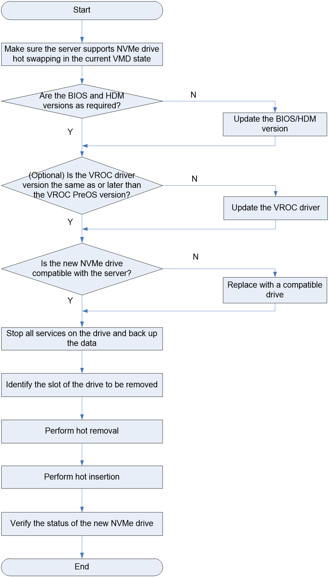
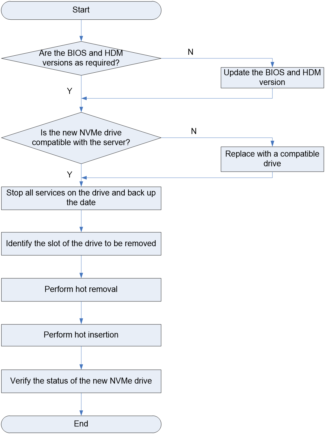
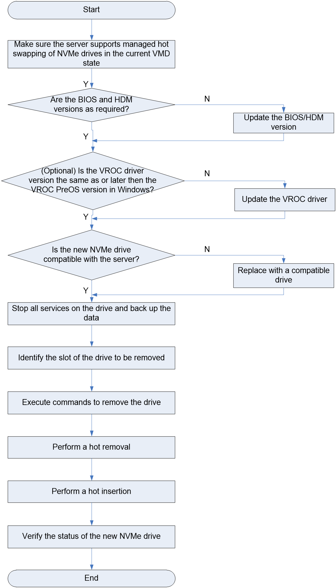
Hot swapping flowchart
Figure 1 Hot swapping flowchart
Performing hot removal
Performing hot removal in Windows
|
|
NOTE: The Windows operating system supports hot removal only when the VMD state is set to Auto/Enabled. It does not support hot removal when the VMD state is set to Disabled. |
Prerequisites
Before replacing an NVMe drive in Windows, make sure the driver version of Intel® VROC is consistent with or later than the version of VROC PreOS in the BIOS. You can access the H3C official website to obtain the latest driver version of Intel® VROC.
To query the VROC driver version and VROC PreOS version:
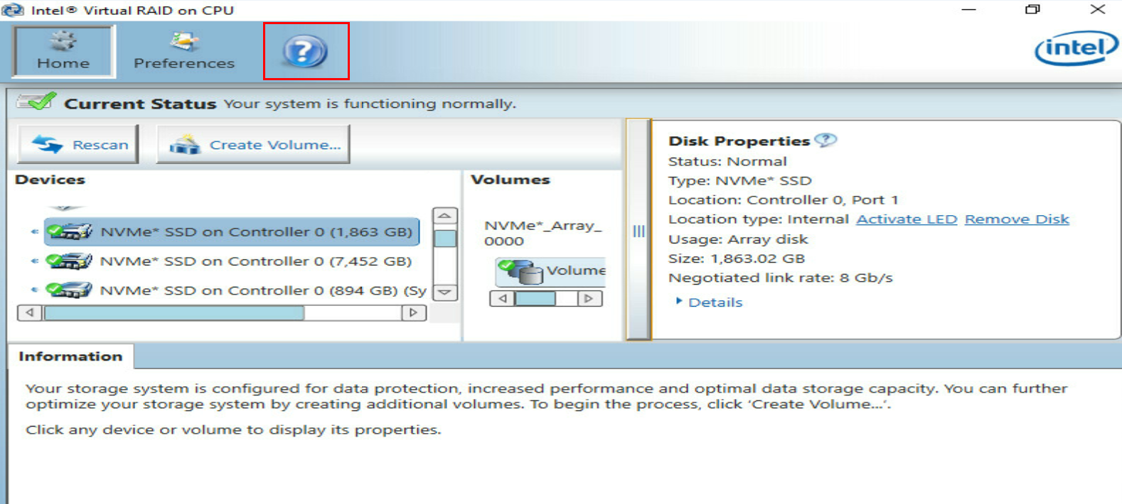
1. Obtain and open Intel®Virtual
RAID on CPU, and click the ![]() icon
on the navigation bar, as shown in Figure 2.
icon
on the navigation bar, as shown in Figure 2.
|
|
IMPORTANT: To obtain Intel® Virtual RAID on CPU, use one of the following methods: · Go to the H3C official website and download the software. · Use an Intel authorized account to log in to the Intel official website and download the software. The tool user guide is included in the installation package. You can refer to the guide to install and use the tool. |
Figure 2 Clicking the question icon on the navigation bar
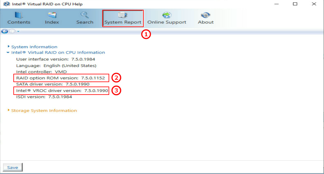
2. Click System Report on the navigation bar, as shown by the callout 1 in Figure 3.
a. View the version information of VROC PreOS, as shown by the callout 2 in Figure 3.
b. View the version information of Intel® VROC, as shown by the callout 3 in Figure 3.
Figure 3 Viewing VROC PreOS version information
Procedure
1. Stop services on the NVMe drive.
2. Back up the drive data.
3. Run Intel® Virtual RAID on CPU to view NVMe drives.
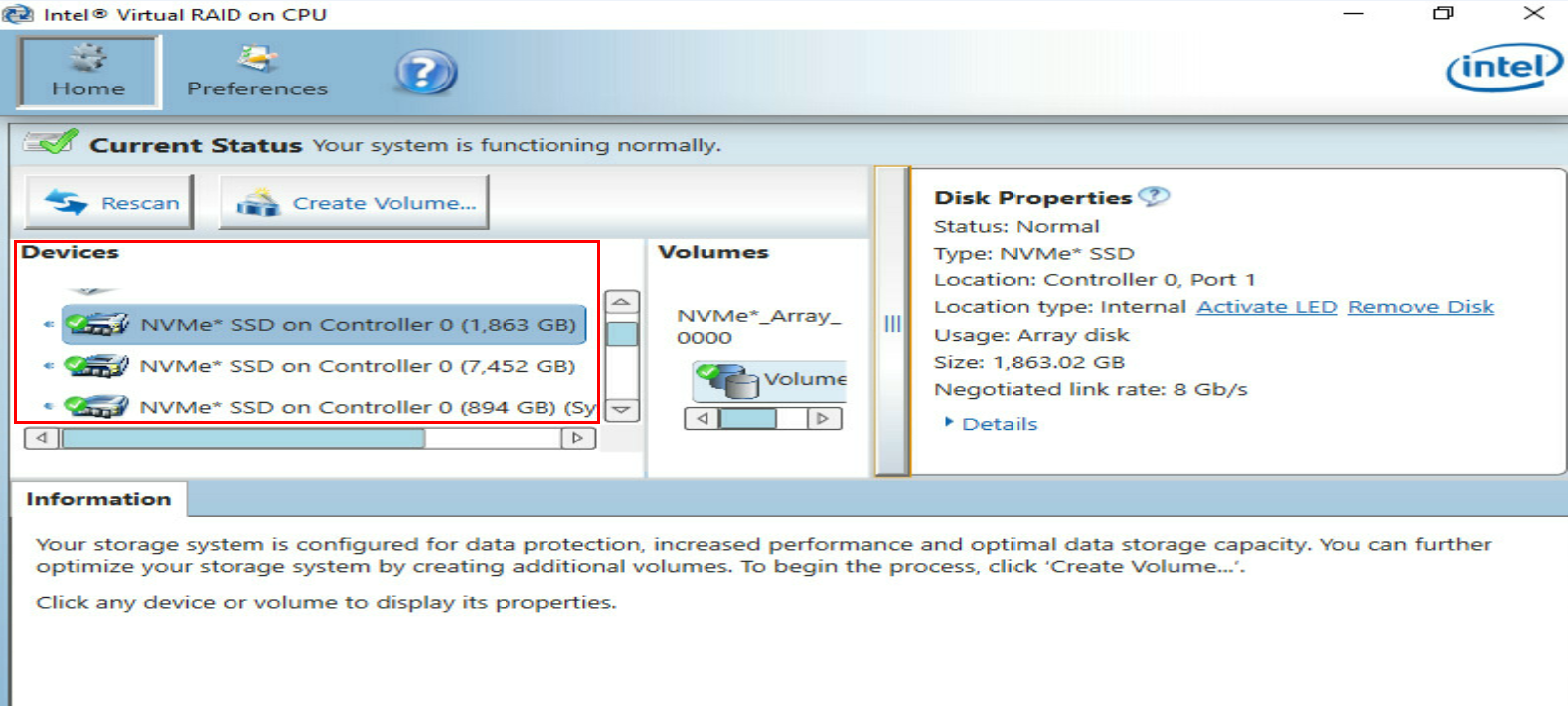
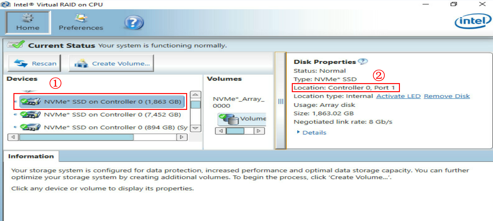
4. Select the NVMe drive to be removed from the Devices list and identify the drive location.
This example removes the NVMe drive from Controller 0, Port1.
Figure 5 Identifying the NVMe drive location

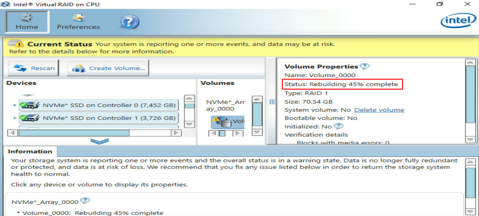
¡ If RAID rebuild is in progress, wait for the process to finish.
|
|
CAUTION: To avoid data loss, do not perform any operations on the NVMe drive during RAID rebuild. |
Figure 6 RAID rebuild in progress
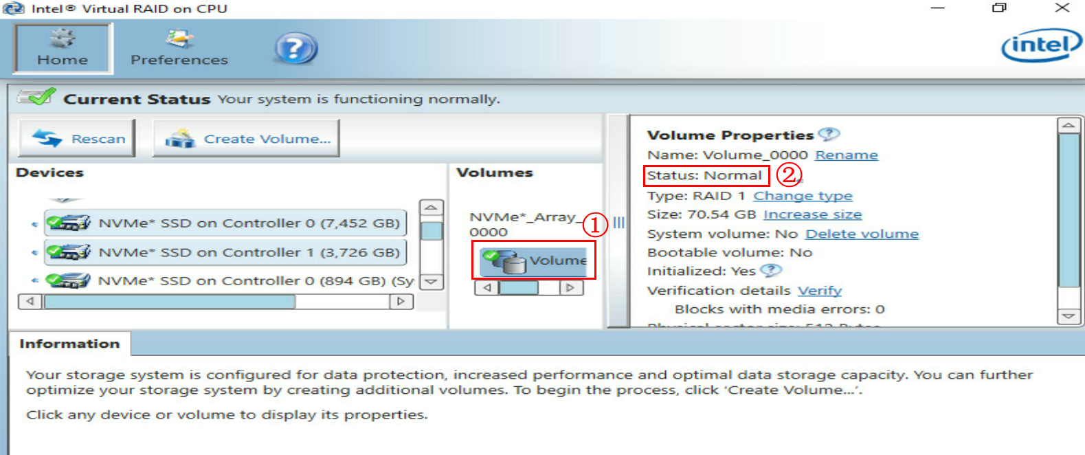
¡ If RAID rebuild is complete (hot spares become the member drives), go to step 6.
Figure 7 RAID rebuild completed
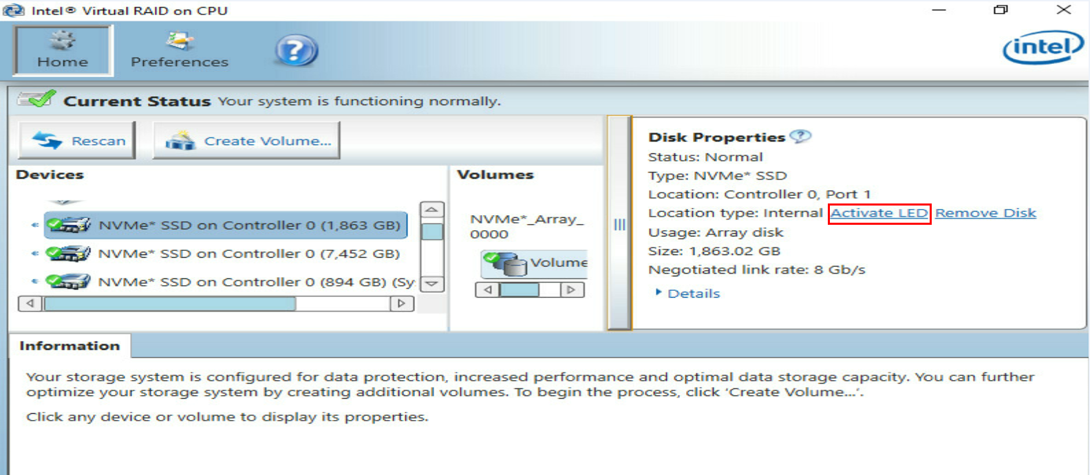
6. Click Activate LED for the drive. The Fault/UID LED on the physical drive will turn steady blue for 10 seconds and then turn off automatically. The Present/Active LED will be steady green.
Figure 8 Activating the LEDs for the NVMe drive
7. Remove the NVMe drive. The removal method is similar for different server models.
|
|
CAUTION: · Do no perform frequent swapping. If you swap a drive repeatedly within 30 seconds, the system might fail to identify the drive. · To avoid system errors, remove only one drive at a time. To remove multiple drives, uninstall them one after another, and remove one drive only after you completely remove the previous one. |
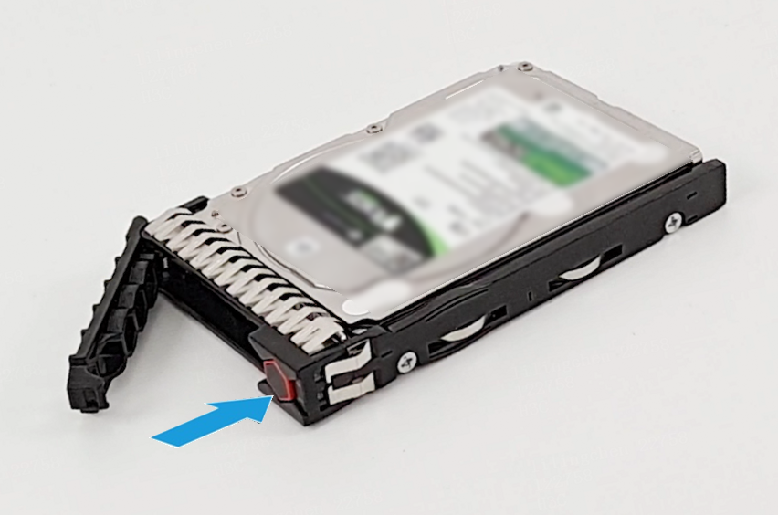
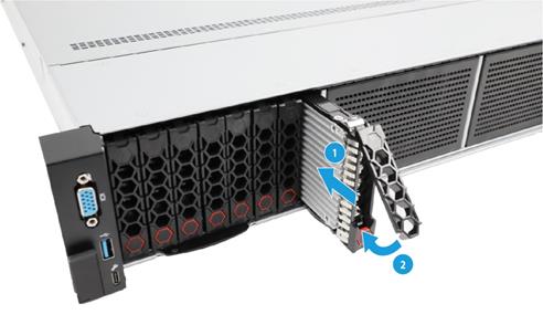
a. Press the button on the drive panel to release the locking lever, as shown by the callout 1 in Figure 9.
b. Pull the drive out of the drive cage, as shown by the callout 2 in Figure 9.

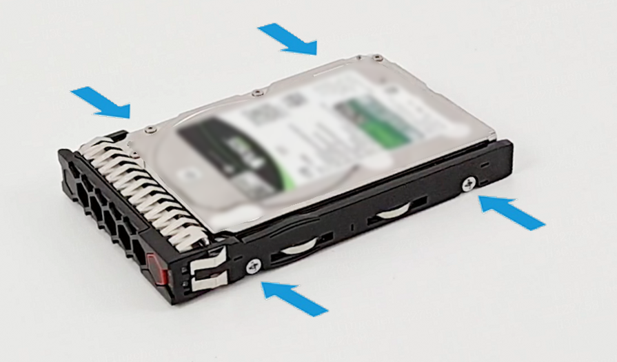
c. Remove the drive from the carrier. Remove all screws that secure the drive on the carrier, and remove the drive from the carrier.
Figure 10 Removing the drive from the carrier

d. Place the removed drive into an antistatic bag.
|
|
CAUTION: Do not place two components into one antistatic bag. |
Performing hot removal in Linux (VMD in Auto/Enabled state)
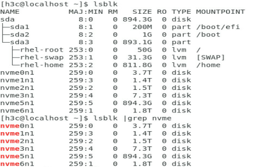
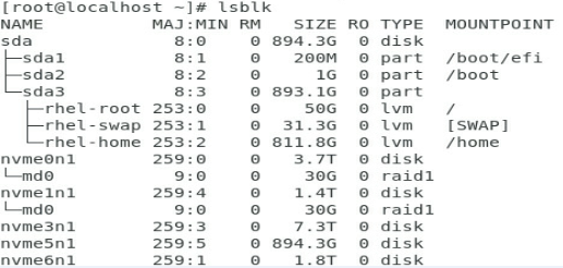
1. Execute the lsblk | grep nvme command to identify the drive letter of the NVMe drive to be removed.
This procedure uses NVMe drive nvme2n1 as an example.
Figure 11 Identifying the drive letter of the NVMe drive to be removed

2. Stop services on the NVMe drive.
3. Back up the drive data.
4. Identify the type of the drive to be removed:
¡ For a passthrough drive, proceed to step 5.
¡ For a member drive in a RAID setup configured with hot spares, proceed to step 6.
¡ For a member drive in a RAID setup that is not configured with hot spares, proceed to step 7.
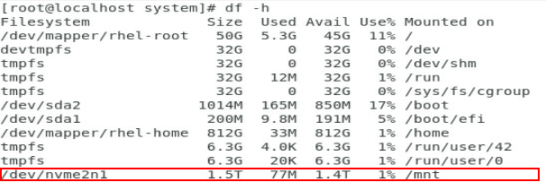
5. If the NVMe drive is a passthrough drive:
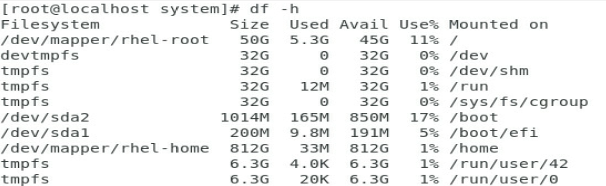
a. Execute the df -h command to identify the mounting status of the NVMe drive. As shown in Figure 12, drive nvme2n1 has been mounted.
Figure 12 Viewing the mounting status of the NVMe drive
b. Execute the umount /dev/nvme2n1 command to unmount the drive.
Figure 13 Unmounting the NVMe drive
![]()
c. Execute the df –h command again and verify that the drive has been unmounted.
Figure 14 Verifying that the drive has been unmounted
d. Move on to step 8.
6. If the NVMe drive is in a RAID setup with hot spares configured:
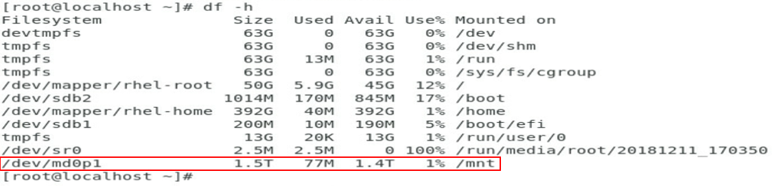
a. Execute the df –h command to identify the mounting status of the NVMe drive. As shown in Figure 15, drive md0p1 has been mounted.
Figure 15 Viewing the mounting status of the NVMe drive
b. Execute the umount /dev/md0p1 command to unmount the drive.
Figure 16 Unmounting the NVMe drive
![]()
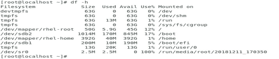
c. Execute the df –h command again and verify that the drive has been unmounted.
Figure 17 Verifying that the drive has been unmounted
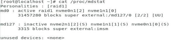
d. Execute the cat /proc/mdstat command to view the RAID rebuild status.
|
|
CAUTION: To avoid data loss, do not perform any operations on the NVMe drive during RAID rebuild. |
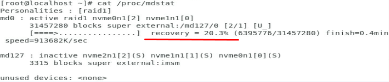
- If RAID rebuild is in progress as shown in Figure 18, wait for the process to finish.
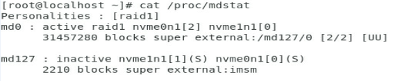
- If RAID rebuild is complete (hot spares become the member drives) as shown in Figure 19, proceed to the next step.
Record the number of the container in which the drive resides before proceeding to the next step. In this example, the number is /md127.
Figure 18 RAID rebuild in progress
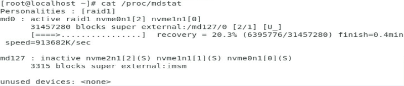
Figure 19 RAID rebuild completed
e. Execute the mdadm –r /dev/md127 /dev/nvme2n1 command to remove drive nvme2n1 from the container, as shown in Figure 20.
Figure 20 Removing the NVMe drive from the container
![]()
f. Execute the cat /proc/mdstat command and verify if the drive has been removed successfully. As shown in Figure 21, the drive has been removed from the container.
Figure 21 Verifying the drive removal
g. Go to step 8
7. If the NVMe drive is in a RAID setup without hot spares configured, perform the following tasks:
a. Verify the NVMe drive mounting status. If the drive has been mounted, unmount it. For more information, see step a.
b. Proceed to the next step.
8. Identify the location of the NVMe drive on the server.
a. Execute the find /sys/devices –iname nvme2n1 command to identify the bus number of the drive. As shown in Figure 22, the bus number for the drive is 10000:04:00.0.
Figure 22 Identifying the bus number
![]()
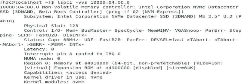
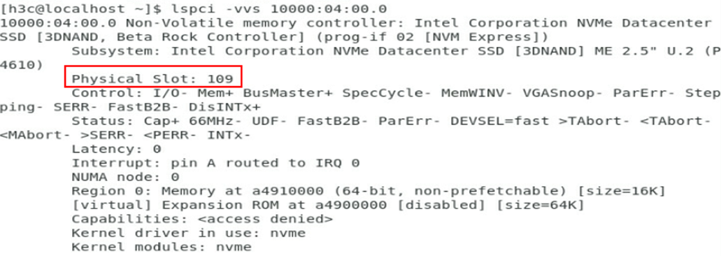
b. Execute the lspci –vvs 10000:04:00.0 command to identify the PCIe slot number. As shown in Figure 23, the PCIe slot is 109.
Figure 23 Identifying the PCIe slot number

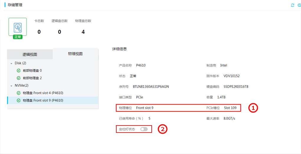
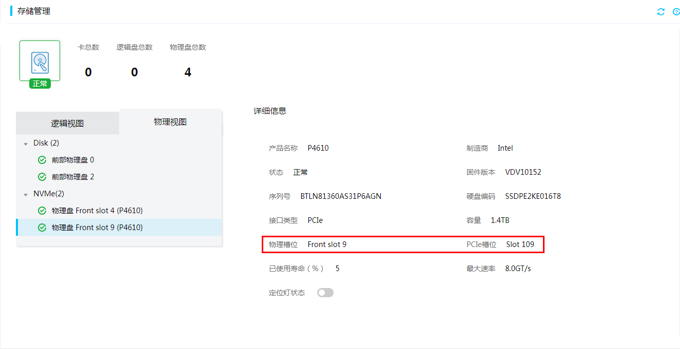
c. Identify the physical slot number of the drive according to the obtained PCIe slot number. Log in to HDM, access the Storage > Physical View page, and identify the physical slot number in HDM for the PCIe slot number. In this example, the physical slot in HDM is Front slot 9.
Items on HDM Web page might vary by HDM version, but the procedures to view NVMe drive information are similar.
Figure 24 Identifying the physical slot number in HDM
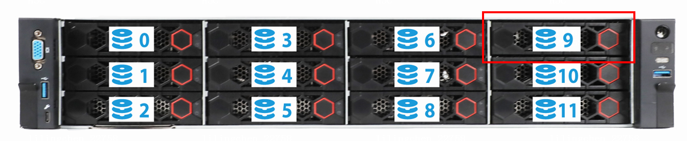
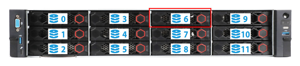
d. Use Figure 25 to identify the drive slot number on the server. In this example, Front slot 9 in HDM represents slot 9 on the server, as shown by Figure 26. You can view the drive slot number mappings in the appendixes of the server user guide.
|
|
NOTE: For the drive slot mappings for G3 servers, contact Technical Support. |
Figure 25 Drive slot number mappings

Figure 26 Drive slot numbering on a server
e. On the HDM Web interface as shown in Figure 24, turn on the UID LED. The Fault/UID LED of the NVMe drive turns steady blue to help drive identification.
9. Remove the NVMe drive. For more information, see step 7 in "Performing hot removal in Windows."
Performing hot removal in Linux (VMD in Disabled state)
Prerequisites (only for G5 servers)
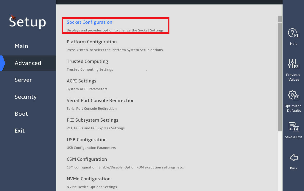
Before performing operations on G5 servers, make sure the OS-Aware & Surprise Hotplug function is enabled in the BIOS. To enable this function:
1. Access the BIOS Setup utility, and select Advanced > Socket Configuration.
Figure 27 Accessing the Socket Configuration screen
|
|
NOTE: The options may vary by the BIOS version, but the operating methods are similar. |
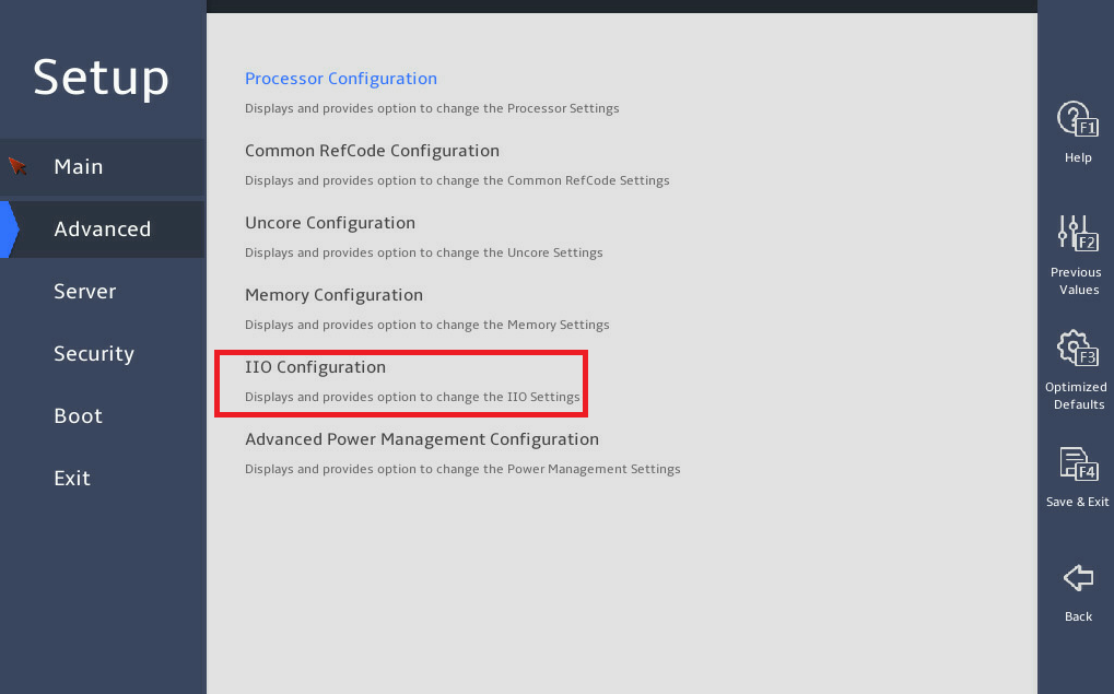
2. Select IIO Configuration.
Figure 28 Selecting IIO Configuration
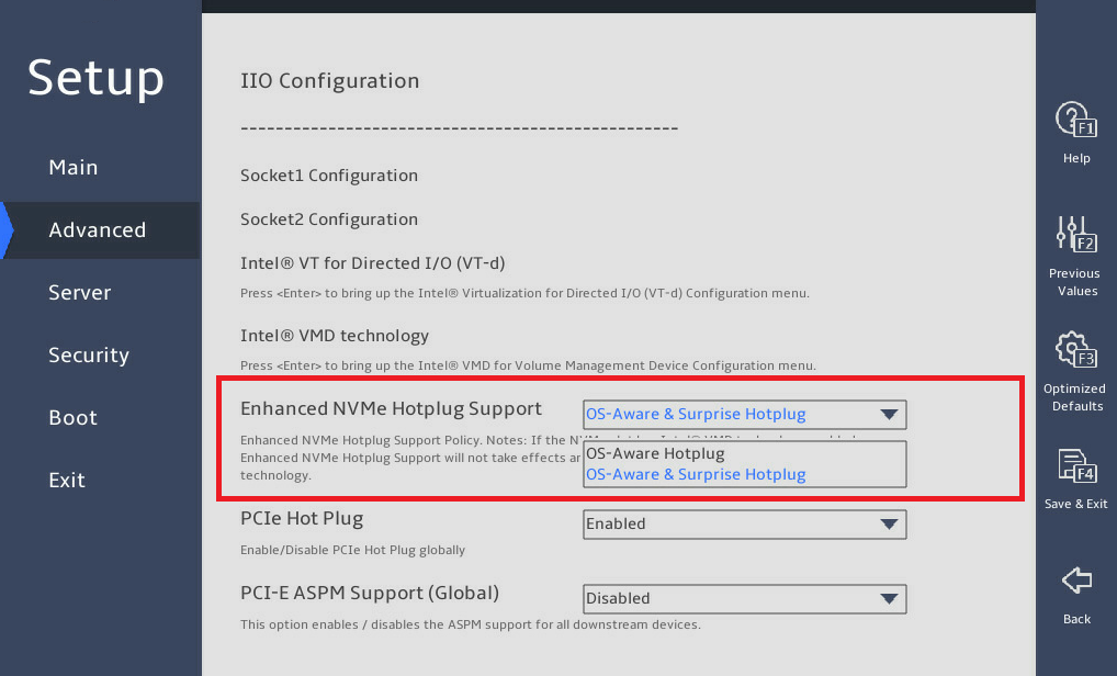
3. Select OS-Aware & Surprise Hotplug from the Enhanced NVMe Hotplug Support field.
Figure 29 Selecting the OS-Aware & Surprise Hotplug option
Procedure
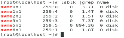
1. Identify the drive letter of the NVMe drive to be removed. Open the OS CLI, and execute the lsblk |grep nvme command to view the drive letter.
|
|
NOTE: This section uses drive letter nvme2n1 as an example. |
Figure 30 Viewing the NVMe drive letter
2. Stop services on the NVMe drive to be removed.
3. Back up data on the NVMe drive to be removed.
4. When VMD is disabled, all NVMe drives are passthrough drives. Check the mounting status of the NVMe drive to be removed. If the NVMe drive is already mounted, unmount it first.
a. Execute the df –h command to view the mounting status of the NVMe drive. As shown in Figure 31, NVMe drive nvme2n1 is mounted.
Figure 31 View the mounting status of the NVMe drive

b. Execute the umount /dev/nvme2n1 command to unmount the drive. As shown in Figure 32, unmount NVMe drive nvme2n1.
Figure 32 Unmount an NVMe drive
![]()
c. Execute the df –h command and verify that the NVMe drive to be removed has been unmounted.
Figure 33 Verifying that the NVMe drive has been unmounted

5. Identify the location of the NVMe drive in the server.
a. View the bus number corresponding to the drive letter. Execute the find /sys/devices -iname nvme2n1 command. In this example, the bus number corresponding to drive letter nvme2n1 is 0000:67:00.0.
Figure 34 Viewing the bus number
![]()
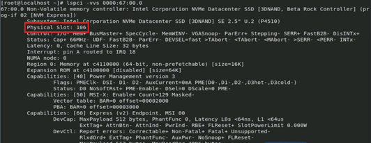
b. Identify the PCIe slot corresponding to the bus number. Execute the lspci -vvs 0000:67:00.0 command. In this case, the PCIe slot number of drive nvme2n1 is 106.
Figure 35 Identifying the PCIe slot number
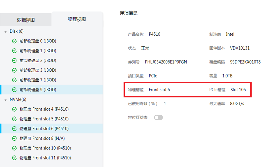
c. Identify the physical slot number corresponding to the PCIe slot number. Log in to the HDM Web interface, select Storage > Physical View. In this example, the physical slot number of PCIe slot Slot 106 is Front slot 6.
Figure 36 Identifying the physical slot number of the PCIe slot
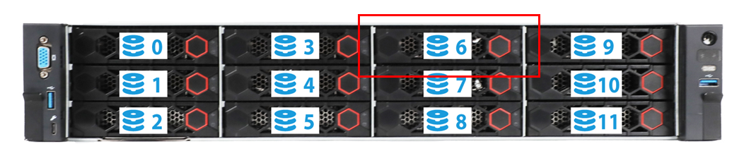
d. Use Figure 37 to identify the drive slot number on the server. In this example, Front slot 6 in HDM represents slot 6 on the server, as shown by Figure 38. You can view the drive slot number mappings in the appendixes of the server user guide.
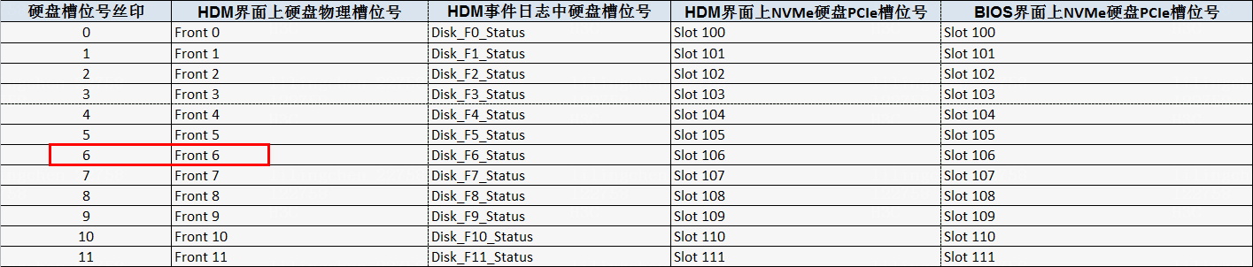
Figure 38 Front drive slot numbering
6. Remove the NVMe drive. For more information, see step 7 in "Performing hot removal in Windows."
Performing hot removal in VMware
|
|
NOTE: The VMware operating system supports hot removal only when the VMD state is set to Auto/Enabled. It does not support hot removal when the VMD state is set to Disabled. |
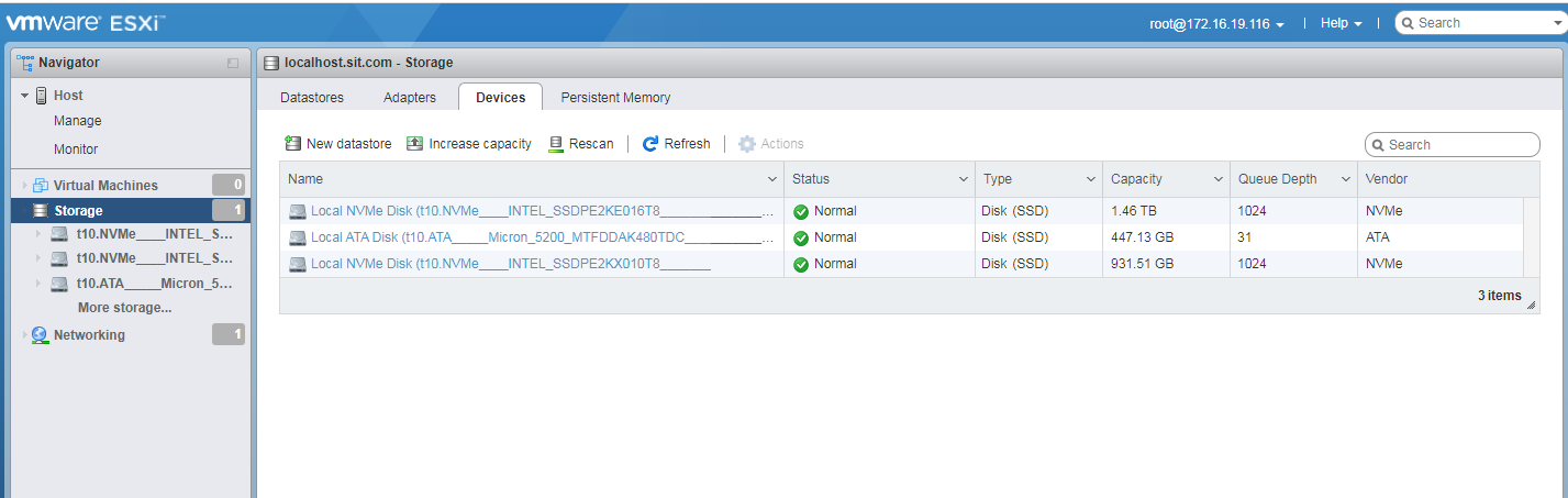
1. Identify the NVMe drive to be removed. As shown in Figure 39, click the Devices tab from the VMware ESXi management GUI.
This procedure uses NVMe drive t10.NVMe__INTEL_SSDPE2KE016T8_______BTLN813609NS1P6AGN_00000001 as an example.
Figure 39 Identifying the NVMe drive to be removed
2. Stop services on the NVMe drive to be removed.
3. Back up the drive data.
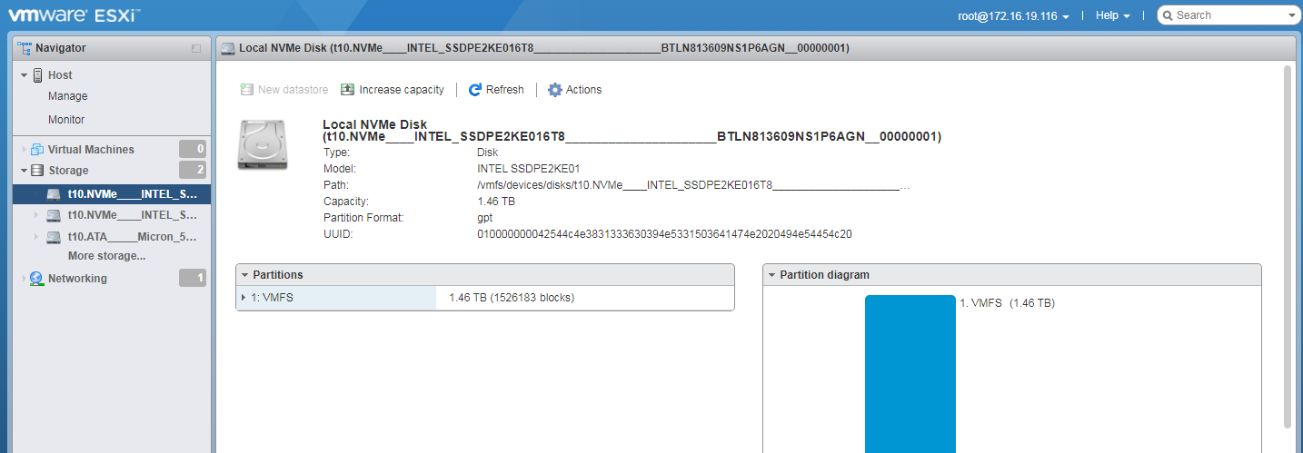
4. Click the drive name to view its mounting status:
¡ If partitions exist, go to step 5 to unmount the drive.
¡ If no partition exists, turn on the LEDs on the drive. For more information, see step 6.
Figure 40 Viewing the mounting status
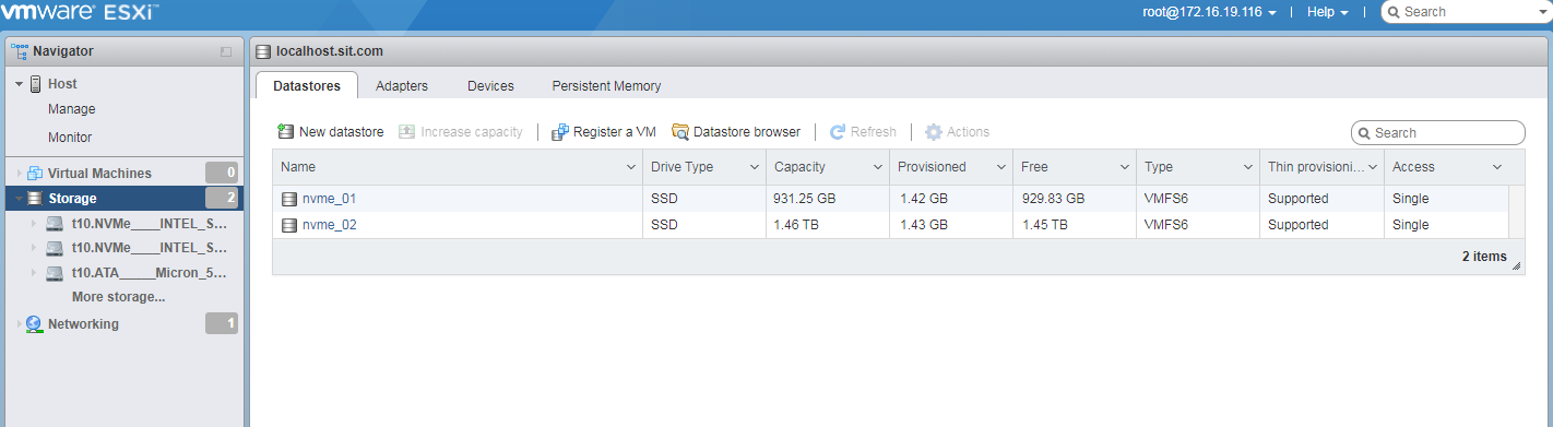
5. (Optional.) Unmount the NVMe drive.
a. Click the Datastores tab to view the mounted NVMe drives.
Figure 41 Viewing the mounted NVMe drives
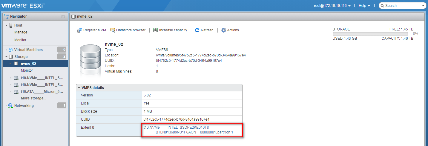
b. Click the drive and verify its name. Make sure it is the drive you are to remove.
Figure 42 Verifying the drive name
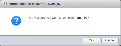
c. Click Actions and then select Unmount from the list that opens. In the dialog box that opens, click Yes.
Figure 43 Unmounting the NVMe drive
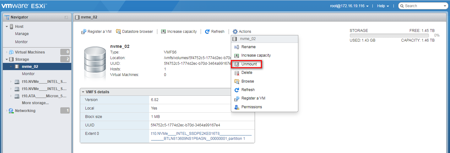
Figure 44 Confirming the drive removal
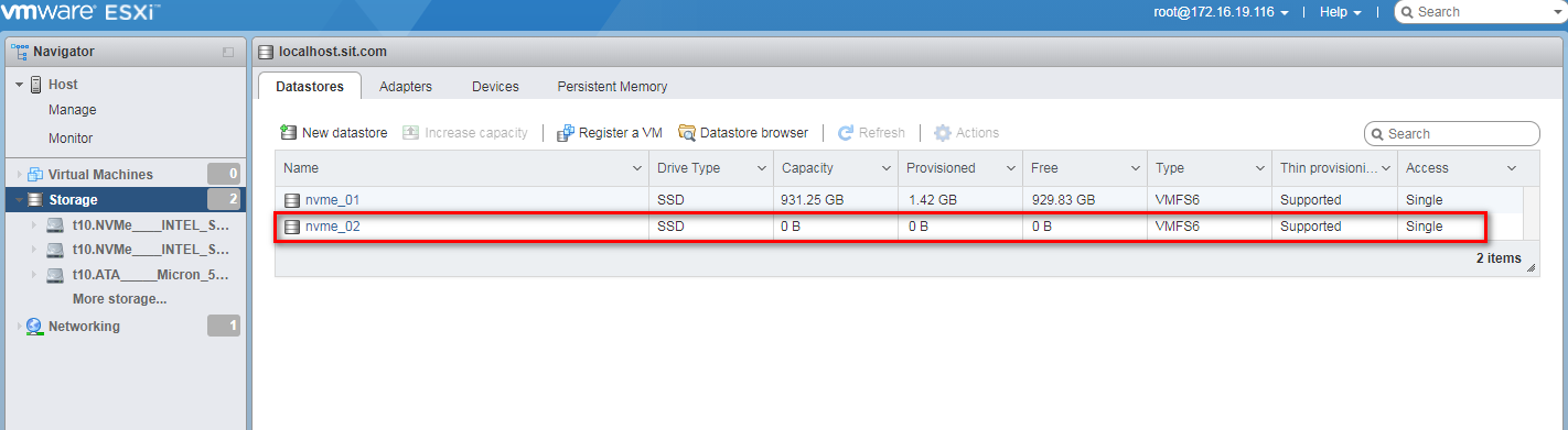
d. Click the Datastores tab to view the drive removal status. As shown in Figure 45, the drive capacity is 0 B, indicating that the NVMe drive has been removed successfully.
Figure 45 Viewing the drive removal status
6. Turn on the LEDs on the NVMe drive to identify the location of the NVMe drive on the server.
The LED lighting tool varies by VROC driver version. For version 2.0 or earlier, the tool name is intel-vmd-user. For versions later than 2.0, the tool name is intel-vmdr-user. You can access the H3C official website to obtain the latest VROC driver compatible with the server. This example uses intel-vmd-user.
a. Execute the esxcfg-mpath –L command to view the SCSI ID for the NVMe drive. As shown in Figure 46, the VMD adapter for the drive is vmhba2 and the drive number is T1.
Figure 46 Viewing the SCSI ID for the NVMe drive
![]()
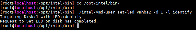
b. Execute the cd /opt/intel/bin/ command to access the directory where the intel-vmd-user tool resides.
Figure 47 Accessing the directory where the tool resides
![]()
c. Execute the /intel-vmd-user set-led vmhba2 –d 1 –l identify command to turn on LEDs on the drive. 1 represents T1, the drive number.
Figure 48 Turning on LEDs on the drive
d. Observe the final state of the LEDs on the NVMe drive. You can remove the NVMe drive after the Fault/UID LED turns steady blue and the Present/Active LED turns steady green.
7. Remove the NVMe drive. For more information, see step 7 in "Performing hot removal in Windows."
Performing hot insertion
The installation method is similar on different servers. This example uses one server model to illustrate the hot insertion method.
Restrictions and guidelines
To avoid system errors, install only one drive at a time. To install multiple drives, insert them one after another, and install one drive only after you completely install the previous one.
Do no perform frequent swapping. If you swap a drive repeatedly within 30 seconds, the system might fail to identify the drive.
If the replaced drive is in a RAID setup, make sure the capacity of the new drive equals to or is larger than the minimum capacity of a member drive in the RAID setup.
Performing hot insertion in Windows
a. Install the drive onto the carrier. Install the four screws into the screw holes and then fasten the screws in sequence.
Figure 49 Installing the drive onto the carrier

b. Press the button on the drive panel to release the locking lever.
Figure 50 Releasing the locking lever
c. Insert the drive into the slot until you cannot push it any further.
|
|
IMPORTANT: To avoid freezing or restarting the operating system, insert the drive at a constant speed and do not pause during the process. |
d. Close the locking lever until you hear a click.
Figure 51 Installing a drive
2. Observe the final state of the LEDs on the NVMe drive. The NVMe drive is present in the slot without any faults if the Present/Active LED is steady green and the Fault/UID LED is off.
3. Run Intel® Virtual RAID on CPU to view the operating status of the NVMe drive as shown in Figure 52. Verify that the drive properties is consistent with the actual drive specifications.
Figure 52 Verifying the status of the installed NVMe drive in Windows
Performing hot insertion in Linux
|
|
NOTE: The hot insertion operation for NVMe drives is similar when VMD is in Auto/Enabled and Disabled state. This section provides an example using VMD state as Auto/Enabled. |
1. Install an NVMe drive. For more information, see "Performing hot insertion in Windows."
2. Observe the final state of the LEDs on the NVMe drive. The NVMe drive is present in the slot without any faults if the Present/Active LED is steady green and the Fault/UID LED is off.
3. Verify that the drive has been identified by the system. Execute the lspci –vvs bus_number command and verify that you can view information about the NVMe drive.
To obtain the bus number, see "Performing hot removal in Linux (VMD in Auto/Enabled state)."
Figure 53 Verifying that the drive has been identified by the system
4. Verify that the drive has been installed correctly. Execute the lsblk command and verify that you can view the drive letter of the drive.
Figure 54 Viewing the drive letter of the drive
Performing hot insertion in VMware
1. Install an NVMe drive. For more information, see "Performing hot insertion in Windows."
2. Observe the final state of the LEDs on the NVMe drive. The NVMe drive is present in the slot without any faults when the Present/Active LED is steady green and the Fault/UID LED is off.
3. Verify that the drive has been installed successfully. Execute the esxcfg-mpath –L command and verify that you can find the drive in the command output.
Figure 55 Verifying that the drive has been installed successfully
![]()
Hot swapping of an NVMe drive NVMe (for AMD/Hygon platform servers)
This chapter describes hot removal and hot insertion procedures.
Hot swapping flowchart
Figure 56 Hot swapping flowchart
Performing hot removal
Performing hot removal in Windows
1. Stop services on the NVMe drive.
2. Back up the drive data.
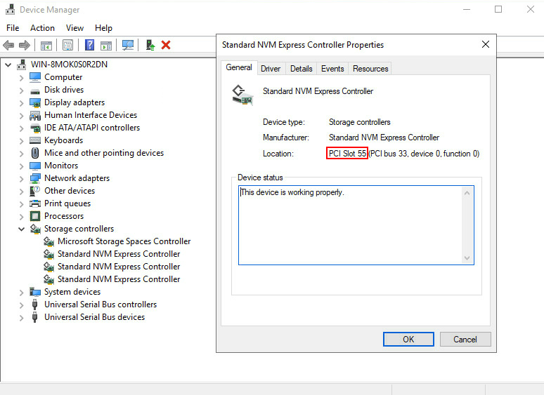
3. Open Device Manager in the operating system, access Storage controllers, and identify slot information of the NVMe drive to be removed. In this example, the NVMe drive to be removed is in PCIe Slot 55.
Figure 57 Identifying the NVMe drive to be removed
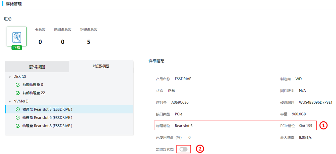
4. Identify the physical slot number corresponding to the PCIe slot number. Log in to the HDM Web interface, select Storage > Physical View. In this example, the physical slot number of PCIe slot Slot 55 is Rear slot 5.
Figure 58 Identifying the physical slot number of the PCIe slot
|
|
NOTE: Options on the HDM Web interface may vary by HDM version, but the drive identification methods are similar. |
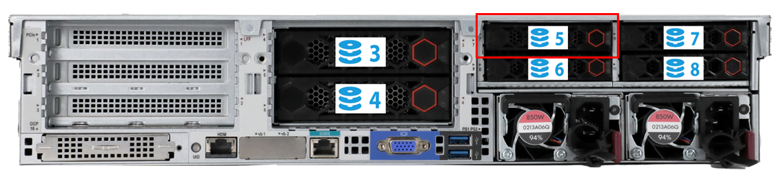
5. Use Figure 59 to identify the drive slot number on the server. In this example, Rear slot 5 in HDM represents slot 5 at the server rear, as shown by Figure 60. You can view the drive slot number mappings in the appendixes of the server user guide.
Figure 59 Drive slot number mappings
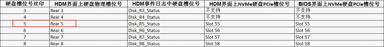
Figure 60 Rear drive slot numbering
6. On the HDM Web interface as shown in Figure 58, turn on the UID LED. The Fault/UID LED of the NVMe drive turns steady blue to help drive identification.
7. Remove the NVMe drive. The removal method is similar for different server models.
|
|
NOTE: · Do no perform frequent swapping. If you swap a drive repeatedly within 30 seconds, the system might fail to identify the drive. · To avoid system errors, remove only one drive at a time. To remove multiple drives, uninstall them one after another, and remove one drive only after you completely remove the previous one. |
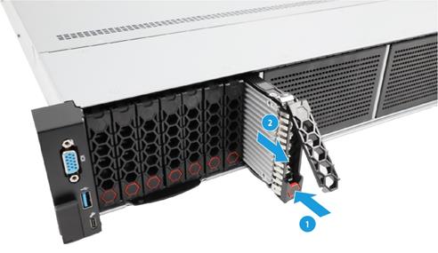
a. Press the button on the drive panel to release the locking lever, as shown by the callout 1 in Figure 61.
b. Pull the drive out of the drive cage, as shown by the callout 2 in Figure 61.
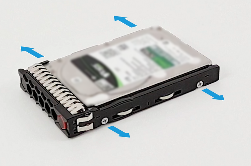
c. Remove the drive from the carrier. Remove all screws that secure the drive on the carrier, and remove the drive from the carrier.
Figure 62 Removing the drive from the carrier
d. Place the removed drive into an antistatic bag.
|
|
CAUTION: Do not place two components into one antistatic bag. |
Performing hot removal in Linux
1. Execute the lsblk | grep nvme command to identify the drive letter of the NVMe drive to be removed.
This procedure uses NVMe drive nvme2n1 as an example.
Figure 63 Identifying the drive letter of the NVMe drive to be removed

2. Stop services on the NVMe drive.
3. Back up the drive data.
4. Execute the df -h command to identify the mounting status of the NVMe drive. In this example, drive nvme2n1 has been mounted.
Figure 64 Viewing the mounting status of the NVMe drive

5. Execute the umount /dev/nvme2n1 command to unmount the drive.
Figure 65 Unmounting the NVMe drive
![]()
6. Execute the df –h command again and verify that the drive has been unmounted.
Figure 66 Verifying that the drive has been unmounted

7. Identify the location of the NVMe drive on the server.
a. Execute the find /sys/devices –iname nvme2n1 command to identify the bus number of the drive. In this example, the bus number for the drive is 10000:04:00.0.
Figure 67 Identifying the bus number
![]()
b. Execute the lspci –vvs 10000:04:00.0 command to identify the PCIe slot number. In this example, the PCIe slot is 109.
Figure 68 Identifying the PCIe slot number
c. Identify the physical slot number of the drive according to the obtained PCIe slot number. Log in to HDM, access the Storage > Physical View page, and identify the physical slot number in HDM for the PCIe slot number. In this example, the physical slot in HDM is Front slot 9.
Figure 69 Identifying the physical slot number in HDM
d. Use Figure 70 to identify the drive slot number on the server. In this example, Front slot 9 in HDM represents slot 9 on the server, as shown by Figure 71. You can view the drive slot number mappings in the appendixes of the server user guide.
Figure 70 Drive slot number mappings
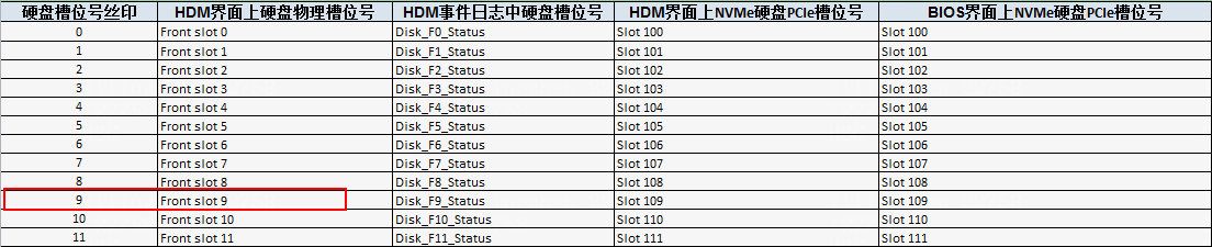
Figure 71 Front drive numbering

8. Remove the NVMe drive. For more information, see step 7 in "Performing hot removal in Windows."
Performing hot insertion
The installation method is similar on different servers. This example uses one server model to illustrate the hot insertion method.
Restrictions and guidelines
To avoid system errors, install only one drive at a time. To install multiple drives, insert them one after another, and install one drive only after you completely install the previous one.
Do no perform frequent swapping. If you swap a drive repeatedly within 30 seconds, the system might fail to identify the drive.
If the replaced drive is in a RAID setup, make sure the capacity of the new drive equals to or is larger than the minimum capacity of a member drive in the RAID setup.
Performing hot insertion in Windows
a. Install the drive onto the carrier. Install the four screws into the screw holes and then fasten the screws in sequence.
Figure 72 Installing the drive onto the carrier
b. Press the button on the drive panel to release the locking lever.
Figure 73 Releasing the locking lever

c. Insert the drive into the slot until you cannot push it any further.
d. Close the locking lever until you hear a click.
Figure 74 Installing a drive

2. Observe the final state of the LEDs on the NVMe drive. The NVMe drive is present in the slot without any faults if the Present/Active LED is steady green and the Fault/UID LED is off.
3. Access the operating system and open Device Manager. In the Disk drivers section, verify that an NVMe drive is newly installed, and the information of the new NVMe drive is consistent with the actual information.
Figure 75 Verifying NVMe installation (in Windows)
Performing hot insertion in Linux
1. Install an NVMe drive. For more information, see "Performing hot insertion in Windows."
2. Observe the final state of the LEDs on the NVMe drive. The NVMe drive is present in the slot without any faults if the Present/Active LED is steady green and the Fault/UID LED is off.
3. Verify that the drive has been identified by the system. Execute the lspci –vvs bus_number command and verify that you can view information about the NVMe drive.
To obtain the bus number, see "Performing hot removal in Linux."
Figure 76 Verifying that the drive has been identified by the system

4. Verify that the drive has been installed correctly. Execute the lsblk command and verify that you can view the drive letter of the drive.
Figure 77 Viewing the drive letter of the drive

Managed hot swapping of an NVMe drive
This chapter describes managed hot removal and hot insertion procedures.
Managed hot removal flowchart
Figure 78 Managed hot removal flowchart
Performing managed hot removal
Performing managed hot removal in Windows (VMD in Auto/Enabled state)
Prerequisites
For more information, see "Prerequisites."
Procedure
1. Stop services on the NVMe drive.
2. Back up the drive data.
3. Run Intel® Virtual RAID on CPU to view NVMe drives. For more information, see step 3 in "Performing hot removal in Windows."
4. Identify the NVMe drive location. For more information, see step 4 in "Performing hot removal in Windows."
5. (Optional.) If the NVMe drive is in a RAID setup configured with hot spares, view the RAID rebuild status. For more information, see step 5 in "Performing hot removal in Windows."
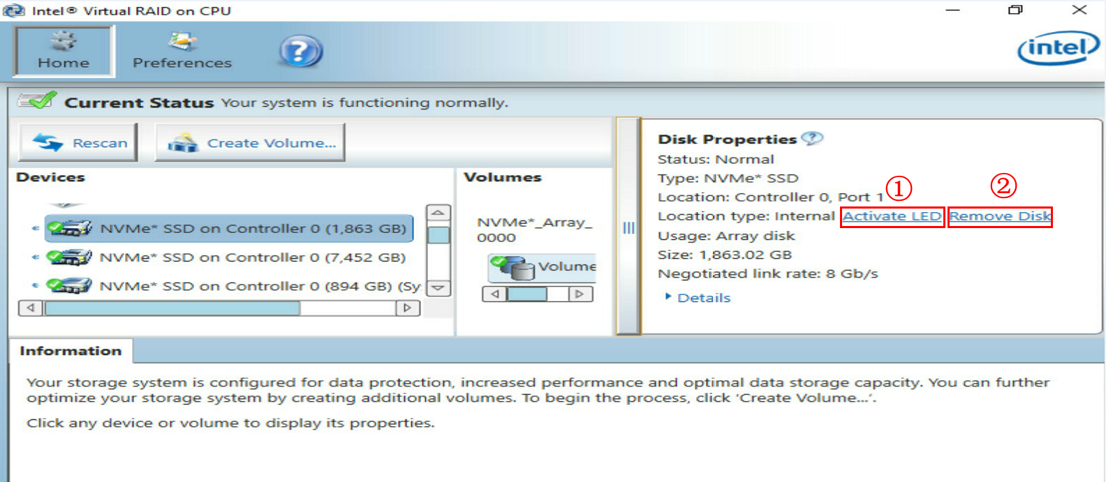
6. Click Activate LED to turn on the LEDs on the drive, as shown by callout 1 in Figure 79. The Fault/UID LED on the physical drive will turn steady blue for 10 seconds and turn off automatically. The Present/Active LED will turn steady green.
7. Click Remove Disk, as shown by callout 2 in Figure 79.
Figure 79 Removing the NVMe drive
8. Observe the drive status. Make sure the Fault/UID LED is steady blue and the Present/Active LED turns steady green, and the NVMe drive is removed from the Devices list of Intel® Virtual RAID on CPU.
9. Remove the NVMe drive. For more information, see step 7 in "Performing hot removal in Windows."
Performing managed hot removal in Windows (VMD in Disabled state)
|
|
NOTE: This section uses Microsoft Windows Server 2019 and PCIe slot 106 as an example. |
1. Stop services on the NVMe drive.
2. Back up the drive data.
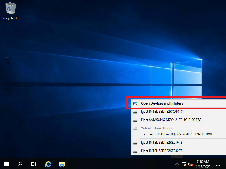
3. Click the ![]() icon
in the menu bar in the operating system, select Open Device and Printers to view all
the NVMe drives on the server.
icon
in the menu bar in the operating system, select Open Device and Printers to view all
the NVMe drives on the server.
Figure 80 Selecting Open Device and Printers
|
|
NOTE: The |
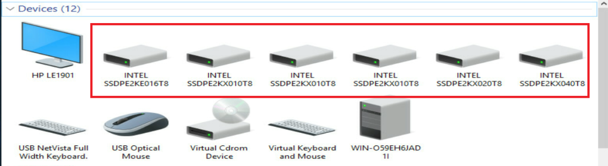
Figure 81 Viewing all the NVMe drives on the server
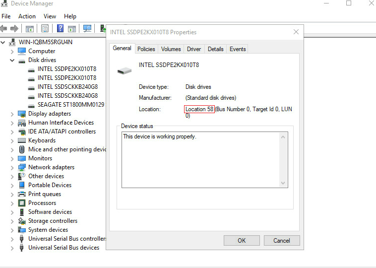
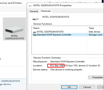
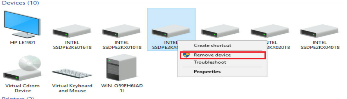
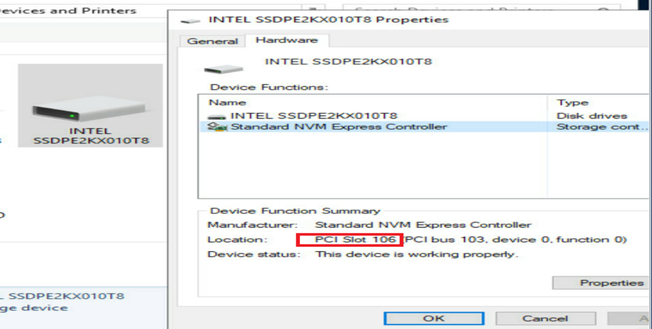
4. Access Properties > Hardware of the drive to identify the slot number of the NVMe drive to be removed. In this example, the slot number is PCIe Slot 106.
Figure 82 Identifying information of the NVMe drive to be removed
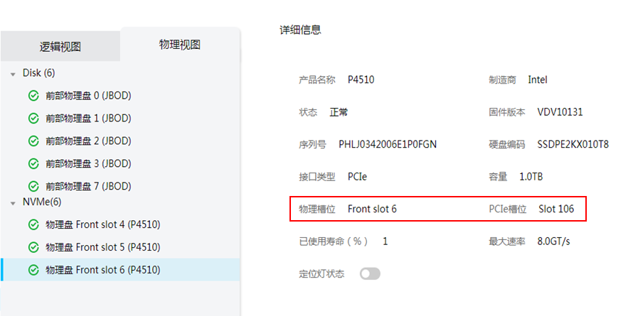
5. Identify the physical slot number of the drive according to the obtained PCIe slot number. Log in to HDM, access the Storage > Physical View page, and identify the physical slot number in HDM for the PCIe slot number. In this example, the physical slot in HDM is Front slot 6.
Figure 83 Identifying the physical slot number in HDM
|
|
NOTE: Options on the HDM Web interface may vary by HDM version, but the methods for viewing NVMe drives are similar. |
6. Use Figure 84 to identify the drive slot number on the server. In this example, Front slot 6 in HDM represents slot 6 on the server, as shown by Figure 85. You can view the drive slot number mappings in the appendixes of the server user guide.
Figure 84 Drive slot number mappings
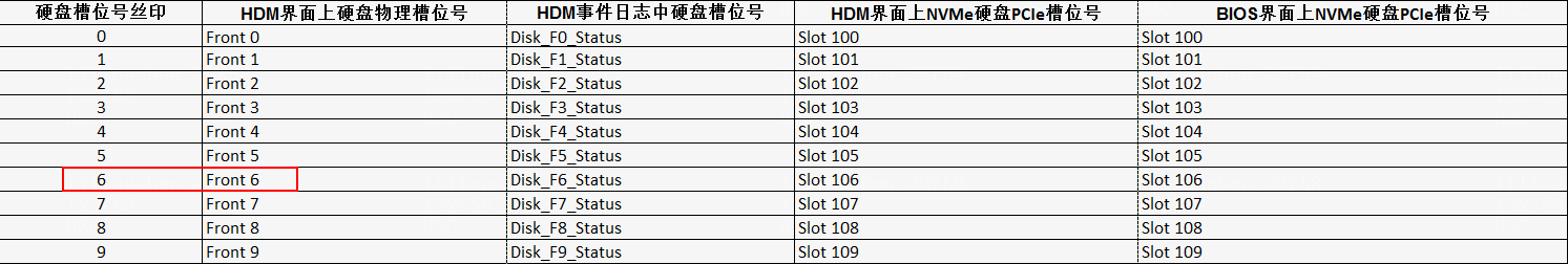
Figure 85 Front drive numbering
7. Right click the NVMe drive to be removed, and select Remove device to remove the drive. Observe the LEDs on the drive. Verify that the Fault/UID LED flashes amber and the Present/Active LED turns off.
Figure 86 Removing the target NVMe drive
8. Remove the NVMe drive. For more information, see step 7 in "Performing hot removal in Windows."
Performing managed hot removal in Linux (VMD in Auto/Enabled state)
|
|
NOTE: This section uses an NVMe drive with driver letter nvme2n1 as an example. |
1. Identify the drive letter of the NVMe drive to be removed. For more information, see step 1 in "Performing hot removal in Linux (VMD in Auto/Enabled state)."
2. Stop services on the NVMe drive.
3. According to the status of the NVMe drive to be removed, perform the following tasks:
¡ For a passthrough drive, view the mounting status of the drive. If the drive has been mounted, first unmount it. For more information, see step 5 in "Performing hot removal in Linux (VMD in Auto/Enabled state)."
¡ For a RAID member configured with hot spares, view the RAID rebuild status. For more information, see step 6 in "Performing hot removal in Linux (VMD in Auto/Enabled state)."
¡ For a RAID member not configured with hot spares, unmount the drive first. For more information, see step 7 in "Performing hot removal in Linux (VMD in Auto/Enabled state)."
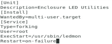
4. (Optional.) Enable ledmon.service as needed. Some Linux operating systems require the ledmon.service before you identify the NVMe drive to be removed.
If the RHEL7.6, RHEL8.0, SUSE15, SUSE15SP1, or SUSE12SP4 operating system is used, create the ledmon.service:
a. Execute the vim /usr/lib/systemed/system/ledmon.service command to create a ledmon.service file.
Figure 87 Creating a ledmon.service file
![]()
b. Edit the file.
Figure 88 Editing the file
c. Start the ledmon.service.
By default, the ledmon.service is disabled in RHEL8.2. You must enable the service manually.
Figure 89 Starting the ledmon.service

If the Ubuntu Server 20.04, Ubuntu Server 20.04.1, or Ubuntu Server 20.04.2 operating system is used, install the ledmon driver first and then enable the ledmon.service:
a. Install the tool packages. Execute the #apt install pkg-config automake autoconf gcc make command to install tools pkg-config, automake, autoconf, gcc, and make.
Figure 90 Installing tools pkg-config, automake, autoconf, gcc, and make
![]()
b. Install the dependencies. Execute the following commands to install libsgutils2-dev, libudev-dev, and libpci-dev:
- #apt install libsgutils2-dev
- #apt install libudev-dev
- #apt install libpci-dev
Figure 91 Installing libsgutils2-dev
![]()
c. Unzip the downloaded ledmon driver source code package and place it in the target path of the operating system. In this section, ledmon-master is used as the target path. Use the #cd ledmon-master command to enter the target path.
Figure 92 Accessing the target path of the ledmon source code
![]()
|
|
NOTE: You can download the ledmon drive source code from github at https://github.com/intel/ledmon. |
d. In the target path, execute the # ./autogen.sh command to install script autogen.sh.
Figure 93 Installing the autogen.sh script
![]()
e. In the target path, execute the # ./configure - -enable-systemd command to install script configure - -enable-systemd.
Figure 94 Installing the configure - -enable-systemd script
![]()
f. In the target path, execute the #make command to compile the ledmon source code.
Figure 95 Compiling the ledmon source code
![]()
g. In the target path, execute the #make install command to install the ledmon driver.
Figure 96 Installing the ledmon driver
![]()
h. Enable the ledmon.service service in the operating system.
Figure 97 Enabling the ledmon.service service in the operating system
![]()
5. Remove the NVMe drive from the operating system and verify the removal:
a. Execute the echo 1 > /sys/block/nvme2n1/device/device/remove command to remove the drive. In this example, drive nvme2n1 is removed.
Figure 98 Removing the NVMe drive
![]()
b. Execute the lsblk command and verify that the drive is not displayed in the command output.
Figure 99 Verifying the removal
6. Observe the final state of the LEDs on the NVMe drive. You can remove the NVMe drive after the Fault/UID LED turns steady amber and the Present/Active LED turns steady green.
7. Remove the NVMe drive. For more information, see step 7 in "Performing hot removal in Windows."
Performing managed hot removal in Linux (VMD in Disabled state)
|
|
NOTE: This section uses an NVMe drive with driver letter nvme2n1 as an example. |
1. Identify the drive letter of the NVMe drive to be removed. For more information, see step 1 in "Performing hot removal in Linux (VMD in Disabled state)."
2. Stop services on the NVMe drive to be removed.
3. View the mounting status of the NVMe drive to be removed. If the drive has been mounted, unmount it first. For more information, see step 4 in "Performing hot removal in Linux (VMD in Disabled state)."
4. Identify the PCIe slot number and location of the NVMe drive to be removed. For more information, see step 5 in "Performing hot removal in Linux (VMD in Disabled state)."
5. Unmount the drive.
a. Use the echo 0 > /sys/bus/pci/slots/106/power command to unmount the drive with drive letter nvme2n1.
Figure 100 Unmounting the drive
![]()
b. Verify that the drive has been unmounted successfully. Execute the lsblk command and verify that drive nvme2n1 is not displayed.
Figure 101 Verifying that the drive has been unmounted successfully

6. Observe the final state of the LEDs on the NVMe drive. You can remove the NVMe drive after the Fault/UID LED turns flashing amber and the Present/Active LED turns off.
7. Remove the NVMe drive. For more information, see step 7 in "Performing hot removal in Windows."
Performing hot insertion
Performing hot insertion in Windows (VMD in Auto/Enabled state)
For more information, see "Performing hot insertion in Windows."
Performing hot insertion in Windows (VMD in Disabled state)
1. Install the NVMe drive. For more information, see step 1 in "Performing hot insertion in Windows."
2. Observe the final state of the LEDs on the NVMe drive. The NVMe drive is present without any faults if the Present/Active LED turns steady green and the Fault/UID LED turns off.
3. Access the operating system. Click the ![]() icon in the menu bar, select Open Device and
Printers, and verify that the NVMe drive has
been installed correctly according to the PCIe slot number.
icon in the menu bar, select Open Device and
Printers, and verify that the NVMe drive has
been installed correctly according to the PCIe slot number.
Figure 102 NVMe drive installed correctly (VMD in Disabled state)
Performing hot insertion in Linux
1. Install the NVMe drive. For more information, see step 1 in "Performing hot insertion in Windows."
2. Observe the final state of the LEDs on the NVMe drive. The NVMe drive is present without any faults if the Present/Active LED turns steady green and the Fault/UID LED turns off.
3. Access the CLI of the operating system, execute the lsblk command. Verify that you can view the drive with driver letter nvme2n1.
Figure 103 NVMe drive installed correctly

Related issues
About VMD
Switching the VMD state
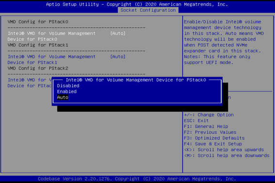
Intel® VMD technology (Intel® Volume Management Device) can switch between different functional states in the BIOS. VMD function includes the following states: Auto, Enabled, and Disabled.
· Auto—The system will automatically enable VMD technology when a device is detected during the POST phase.
· Enabled—VMD technology is enabled, and more detailed configuration options will be displayed.
· Disabled—VMD technology is disabled. You can find this option in Advanced > Socket Configuration.
|
|
NOTE: Options in the BIOS may vary by the BIOS version, but the option meanings and operation methods are similar. |
Using Purley BIOS of G3 products as an example, you can access BIOS Setup > Socket Configuration > IIO Configuration > Intel® VMD technology > Intel@ VMD for Volume Management Device on Processor X to switch the VMD state for any CPU PStack.
Figure 104 Configuring VMD for CPU 1
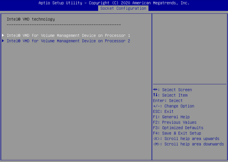
Figure 105 Setting the VMD state
Configurations with VMD Enabled
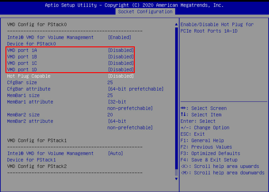
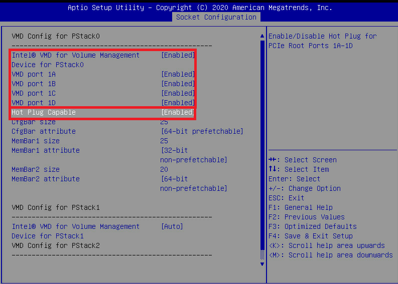
With VMD enabled, you can individually configure the ports under each PStack. Taking CPU1's PStack0 as an example, when the Intel® VMD for Volume Management option is set to Enabled, a specific menu will be displayed. In this menu, you can configure each port under PStack0 individually. As shown in Figure 106, this PStack contains the following ports: VMD port 1A, VMD port 1B, VMD port 1C, and VMD port 1D.
Figure 106 CPU1 PStack0 menu with VMD enabled
|
|
NOTE: VMD ports correspond to different ports of the server's PCIe link. The mappings may vary by device model. |
Enabling managed hot swapping and hot swapping of NVMe drives
1. Set all the VMD port xx and Hot Plug Capable fields to Enabled.
Figure 107 Setting all the VMD port xx and Hot Plug Capable to Enabled
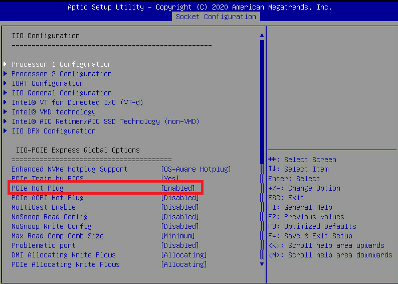
2. Access the BIOS Setup > Socket Configuration > IIO Configuration screen, and press Ctrl+Shift+P to open the hidden menu. Make sure the PCIe Hot plug field is set to Enabled. By default, this field is set to Enabled.
Figure 108 Hidden menu in IIO Configuration
Operating mode of the new drive
· If the removed NVMe drive is a passthrough drive, the new NVMe drive also functions as a passthrough drive.
· The new drive functions as a passthrough drive in the following situations even if RAID is configured for the removed drive:
¡ The removed NVMe drive is a member drive in a RAID setup that does not offer redundancy.
¡ The removed NVMe drive is a member drive in a RAID setup that offers redundancy, but the drive does not have hot spares and is disabled with RAID rebuild.
¡ The removed NVMe drive is a member drive in a RAID setup that offers redundancy and is configured with hot spares.
You can configure RAID as needed. For more information, see the storage controller user guide.
RAID rebuild
If you removed an NVMe drive in a redundant RAID setup configured with no hot spares but enabled with RAID rebuild, the storage controller automatically rebuild the RAID after the replacement.
Procedures for viewing the RAID rebuild status vary by operating system.
Support for RAID rebuild and the default feature state depends on storage controllers. For more information, see the storage controller user guide.
Make sure the capacity of the new drive equals to or is larger than the minimum capacity of a member drive in the RAID setup.
Viewing the RAID rebuild status in Windows
Run Intel® Virtual RAID on CPU to view the RAID rebuild status.
Figure 109 RAID rebuild completed

Figure 110 RAID rebuild in progress

Viewing the RAID rebuild status in Linux
For a RAID setup configured with hot spares and enabled with RAID rebuild
1. Remove the old drive after the RAID rebuild is complete. For more information, see step 4 in "Performing hot removal in Linux (VMD in Auto/Enabled state)."
2. Install the new drive. If the Present/Active LED is green and the Fault/UID LED is steady amber, the new NVMe drive functions as a passthrough drive.
3. Execute the ledctl off=/dev/<name of the new drive> command, and turn off the Fault/UID LED, as shown in Figure 111.
Figure 111 Turning off the Fault/UID LED
![]()
4. (Optional.) Execute the mdadm -a /dev/<container name > /dev/<name of the new drive> command to add the new drive into the old RAID container. The new drive functions as a hot spare.
For a RAID setup configured with no hot spares and enabled with RAID rebuild
1. After installing the new drive, the Present/Active LED turn green and the Fault/UID LED turns steady amber. Before the RAID rebuild, you must add the new drive into the container. Execute the mdadm -a /dev/<the name of the container> /dev/<the name of the new drive> command to add the new drive into the container. The storage controller will automatically rebuild the RAID.
2. Execute the cat /proc/mdstat command to view the RAID rebuild status.
Figure 112 RAID rebuild completed
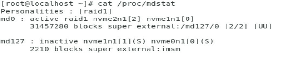
Figure 113 RAID rebuild in progress
3. After the RAID rebuild complete, verify that the Fault/UID LED turns off and the Present/Active LED turns steady green.
