- Table of Contents
-
- 06-Internet Access Behavior Management
- 01-Denying Users Internet Access Configuration Examples (Web)
- 02-ER G3 Routers MAC Filter Configuration Examples
- 03-MSR Routers URL-Based Access Control Configuration Examples
- 04-MSR Routers Bandwidth Guarantee Configuration Examples (CLI)
- 05-MSR Routers Rate Limiting Configuration Examples (CLI)
- 06-MSR Routers Rate Limiting Configuration Examples (Web)
- 07-MSR Routers Application Control Configuration Examples
- Related Documents
-
| Title | Size | Download |
|---|---|---|
| 02-ER G3 Routers MAC Filter Configuration Examples | 371.19 KB |
ERG3 Routers
MAC Filter Configuration Examples
Copyright © 2024 New H3C Technologies Co., Ltd. All rights reserved.
No part of this manual may be reproduced or transmitted in any form or by any means without prior written consent of Hangzhou H3C Technologies Co., Ltd.
Except for the trademarks of New H3C Technologies Co., Ltd., any trademarks that may be mentioned in this document are the property of their respective owners.
The information in this document is subject to change without notice.
Introduction
The following information provides MAC filter configuration examples.
Prerequisites
This document is not restricted to specific software or hardware versions. Procedures and information in the examples might be slightly different depending on the software or hardware version of the device.
The configuration examples were created and verified in a lab environment, and all the devices were started with the factory default configuration. When you are working on a live network, make sure you understand the potential impact of every command on your network.
The following information is provided based on the assumption that you have basic knowledge of ACL and QoS.
Example: Configuring MAC filter
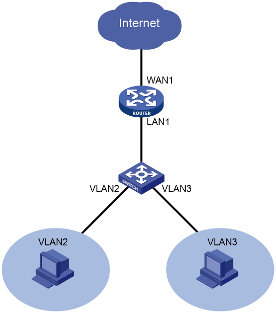
Network configuration
As shown in Figure 1, the router serves as the egress router on the enterprise network and is configured with VLANs VLAN2 and VLAN3. VLAN2's interface resides on subnet 192.168.2.0/24 and VLAN3's interface resides on subnet 192.168.3.0/24.
Configure MAC filter to control Internet access:
· Permit users on VLAN2 to access the Internet.
· Forbid the user with MAC address 509A-4CDA-1ECB on VLAN3 from accessing the Internet and permit other users on VLAN3 to access the Internet.
Software versions used
This configuration example was created and verified on Release 0136 of the ER3200G3 router.
Restrictions and guidelines
For internal users to access the external network, make sure the subnet on which the WAN interface resides is different from the internal subnets.
Procedures
Connecting interface WAN1 to the Internet
1. On the Web interface of the device, select Network Settings > External Networks.
2. Click the WAN Settings tab.
3. Click the edit icon in the Actions column for WAN1.
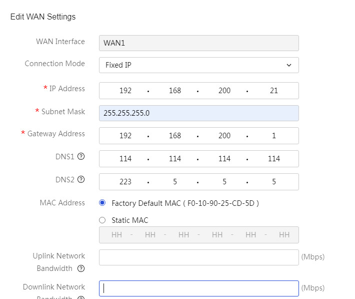
4. In the Connection Mode field, select Fixed IP.
5. In the IP Address field, enter 192.168.200.21.
6. In the Subnet Mask field, enter 255.255.255.0.
7. In the Gateway Address field, enter 192.168.200.1.
8. Use the default settings for the other parameters. Click Apply.
Figure 2 Editing WAN settings
Configuring VLAN2 and the interface IP address
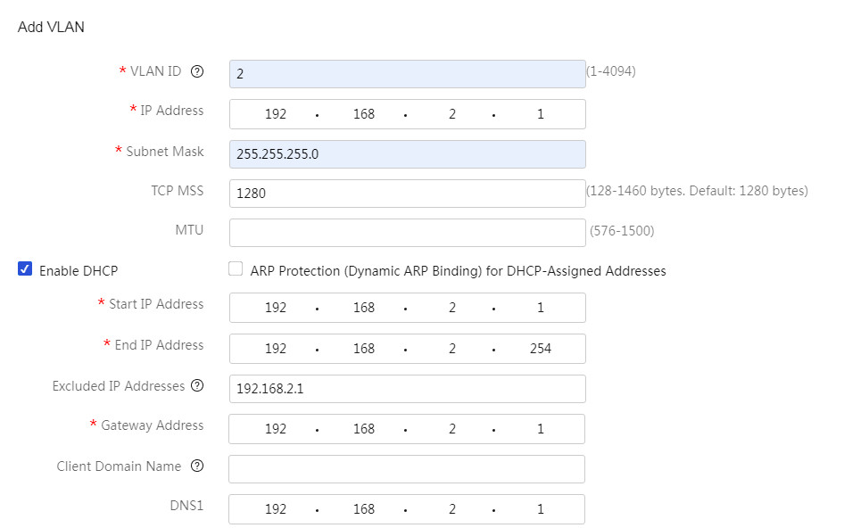
# On the router, configure VLAN2 and configure its interface IP address as 192.168.2.1/24.
1. On the Web interface of the device, select Network Settings > LANs from the navigation pane. Click the VLAN Settings tab.
2. Click Add.
3. In the VLAN ID field, enter 2.
4. In the IP Address field, enter 192.168.2.1.
5. In the Subnet Mask field, enter 255.255.255.0.
6. Select Enable DHCP.
7. Use the default settings for the other parameters. Click Apply.
Figure 3 Configuring VLAN2
Configuring VLAN3 and the interface IP address
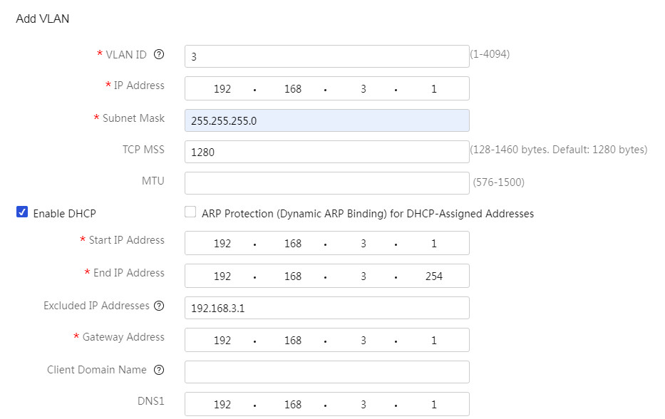
# On the router, configure VLAN3 and configure its interface IP address as 192.168.3.1/24.
1. On the Web interface of the device, select Network Settings > LANs from the navigation pane. Click the VLAN Settings tab.
2. Click Add.
3. In the VLAN ID field, enter 3.
4. In the IP Address field, enter 192.168.3.1.
5. In the Subnet Mask field, enter 255.255.255.0.
6. Select Enable DHCP.
7. Use the default settings for the other parameters. Click Apply.
Figure 4 Configuring VLAN3
Assigning interface LAN1 to VLAN2 and VLAN3
1. On the Web interface of the device, select Network Settings > LANs from the navigation pane.
2. On the VLAN Division tab, click the edit icon in the Actions column for LAN1.
3. Select VLAN2 and VLAN3 from the left box.
4. Click the > icon.
5. Click Apply.
Figure 5 Detailed port settings page

Configuring MAC filter
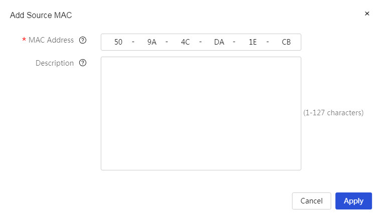
# Add MAC address 509A-4CDA-1ECB to the denylist.
1. On the Web interface of the device, select Security > MAC Filter from the navigation pane.
2. Select MAC Denylist and Allowlist > Denylist.
3. Click Add.
4. In the MAC Address field, enter 50-9A-4C-DA-1E-CB.
5. Click Apply.
Figure 6 Adding a source MAC address to the denylist
# Enable MAC filter for port VLAN3.
6. On the Web interface of the device, select Security > MAC Filter from the navigation pane.
7. On the MAC Filter Settings tab, select Enable MAC Filter.
8. Select the Denylist filtering method and Enable for port VLAN3.
9. Click Apply.
Figure 7 MAC filter settings page

Verifying the configuration
1. Verify that the users on VLAN2 can access the Internet.
C:\Users\VLAN 2a>ping –S 192.168.2.2 114.114.114.114
Reply from 114.114.114.114: bytes=32 time=73ms TTL=85
Reply from 114.114.114.114: bytes=32 time=91ms TTL=79
Reply from 114.114.114.114: bytes=32 time=82ms TTL=65
Reply from 114.114.114.114: bytes=32 time=103ms TTL=77
Ping statistics for 114.114.114.114:
Packets: Sent = 4, Received = 4, Lost = 0 (0% loss),
Approximate round trip time in milli-seconds:
Minimum = 73ms, Maximum = 103ms, Average = 87ms
2. Verify that the user with MAC address 50-9A-4C-DA-1E-CB on VLAN3 cannot access the Internet.
C:\Users\VLAN 3a>ping –S 192.168.3.2 114.114.114.114
Request timed out.
Request timed out.
Request timed out.
Request timed out.
3. Verify that other users on VLAN3 can access the Internet.
C:\Users\VLAN 3b>ping –S 192.168.3.3 114.114.114.114
Reply from 114.114.114.114: bytes=32 time=73ms TTL=85
Reply from 114.114.114.114: bytes=32 time=91ms TTL=79
Reply from 114.114.114.114: bytes=32 time=82ms TTL=65
Reply from 114.114.114.114: bytes=32 time=103ms TTL=77
Ping statistics for 114.114.114.114:
Packets: Sent = 4, Received = 4, Lost = 0 (0% loss),
Approximate round trip time in milli-seconds:
Minimum = 73ms, Maximum = 103ms, Average = 87ms
