- Table of Contents
-
- 04-Network Configuration
- 01-Access Public and Dedicated Networks Through Multiple WAN Interfaces (CLI)
- 02-Basic Network Access (DHCP-Based IP Address Acquisition) Configuration Examples (CLI)
- 03-ER G3 Routers PPPoE Configuration Examples (Web)
- 04-ER G3 Routers Basic Network Access (DHCP-Based IP Address Acquisition) (Web)
- 05-ER G3 Routers Basic Internet Access (Static IP) Web-Based Configuration Examples
- 06-MER Routers Basic Network Access (DHCP-Based IP Address Acquisition) (Web)
- 07-MER Routers Primary and Backup Network Accesses Through Multiple WAN Interfaces (Web)
- 08-MER Routers PPPoE Configuration Examples (Web)
- 09-MER Routers Access Public and Dedicated Networks Through Multiple WAN Interfaces (Web)
- 10-MER Routers Basic Internet Access (Static IP) Web-Based Configuration Examples
- 11-MSR Routers Basic Network Access (DHCP-Based IP Address Acquisition) (Web)
- 12-MSR Routers Basic Internet Access (Static IP) Web-Based Configuration Examples
- 13-MSR Routers Access Public and Dedicated Networks Through Multiple WAN Interfaces (Web)
- 14-MSR Routers PPPoE Configuration Examples (CLI)
- 15-Router Basic Internet Access (Static IP) CLI-Based Configuration Examples
- Related Documents
-
| Title | Size | Download |
|---|---|---|
| 14-MSR Routers PPPoE Configuration Examples (CLI) | 265.14 KB |
MSR Routers
PPPoE Configuration Examples (CLI)
Copyright © 2024 New H3C Technologies Co., Ltd. All rights reserved.
No part of this manual may be reproduced or transmitted in any form or by any means without prior written consent of New H3C Technologies Co., Ltd.
Except for the trademarks of New H3C Technologies Co., Ltd., any trademarks that may be mentioned in this document are the property of their respective owners.
The information in this document is subject to change without notice.
Contents
Introduction
This document provides examples for configuring PPPoE on routers.
Prerequisites
This document is not restricted to specific software or hardware versions. Procedures and information in the examples might be slightly different depending on the software or hardware version of the device.
The configuration examples were created and verified in a lab environment, and all the devices were started with the factory default configuration. When you are working on a live network, make sure you understand the potential impact of every command on your network.
The following information is provided based on the assumption that you have basic knowledge of PPPoE.
Software versions used
This configuration example was created and verified on Version 7.1.064 Feature 6749L15 of the MSR3610 router.
Configuration example
Network configuration
As shown in Figure 1, a company requires external office staff to access the internal network through PPPoE. The ISP provides a PPPoE account with the username as vpdnuser and the password as user1234, along with DNS addresses 5.5.5.5 and 6.6.6.6.

Analysis
1. Configure an address pool for allocating IP addresses to hosts.
2. Host accesses the company's internal server through PPPoE.
Procedures
Configuring the router
Configuring IP addresses for interfaces
# Enter the view of interface GigabitEthernet 0/1 and configure its IP address as 20.1.1.1/24.
<Router> system-view
[Router] interface gigabitethernet 0/1
[Router-GigabitEthernet0/1] ip address 20.1.1.1 24
[Router-GigabitEthernet0/1] quit
# Enter the view of interface GigabitEthernet 0/2 and configure its IP address as 192.168.2.1/24.
[Router] interface gigabitethernet 0/2
[Router-GigabitEthernet0/2] ip address 192.168.2.1 24
[Router-GigabitEthernet0/2] quit
Configuring a dialer interface
# Configure dialer group 1 to dial through DDR for IP packets.
[Router] dialer-group 1 rule ip permit
# Create dialer interface 1.
[Router] interface dialer 1
# Enable bundle DDR.
[Router-Dialer1] dialer bundle enable
# Create dialer group 1.
[Router-Dialer1] dialer-group 1
# Enable IP address negotiation on the interface, so that the interface can accept the IP address allocated by the server.
[Router-Dialer1] ip address ppp-negotiate
# Configure the PPPoE session to operate in permanent mode.
[Router-Dialer1] dialer timer idle 0
# Configure the account used for dialup.
[Router-Dialer1] ppp chap user vpdnuser
# Configure the password used for dialup.
[Router-Dialer1] ppp chap password simple user1234
# Configure the interface to accept the DNS server IP addresses assigned by the peer even though it does not request DNS server IP addresses from the peer.
[Router-Dialer1] ppp ipcp dns admit-any
# Enable the interface to actively request the DNS server IP address from its peer.
[Router-Dialer1] ppp ipcp dns request
# Configure NAT.
[Router-Dialer1] nat outbound
[Router-Dialer1] quit
# Bind the dialer interface to physical interface GigabitEthernet 0/1.
[Router] interface GigabitEthernet 0/1
[Router-GigabitEthernet0/1] pppoe-client dial-bundle-number 1
[Router-GigabitEthernet0/1] quit
Configuring the default route
# Configure the default route to the Internet.
[Router] ip route-static 0.0.0.0 0 Dialer 1
Configuring address pools
# Enable DHCP.
[Router] dhcp enable
# Create address pool pool1 for address allocation.
[Router] dhcp server ip-pool pool1
# Specify the subnets for address allocation.
[Router-dhcp-pool-pool1] network 192.168.2.0 mask 255.255.255.0
[Router-dhcp-pool-pool1] address range 192.168.2.2 192.168.2.254
# Configure the gateway for the address pool.
[Router-dhcp-pool-pool1] gateway-list 192.168.2.1
# Configure a DNS server address.
[Router-dhcp-pool-pool1] dns-list 5.5.5.5 6.6.6.6
[Router-dhcp-pool-pool1] quit
Configuring the PPPoE client
|
|
NOTE: On Host, configure the PPPoE client. In this example, the PC is installed with Windows 7. |
# Log in to Host. Click the Network ![]() icon
in the lower right corner of the PC, and click Open
Network and Sharing Center.
icon
in the lower right corner of the PC, and click Open
Network and Sharing Center.
Figure 2 Opening the network and sharing center window
![]()
# Click Set up a new connection or network to create an L2TP client.
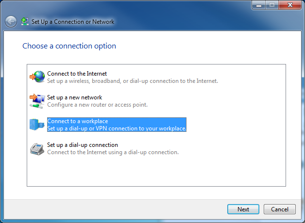
Figure 3 Setting up a new connection or network
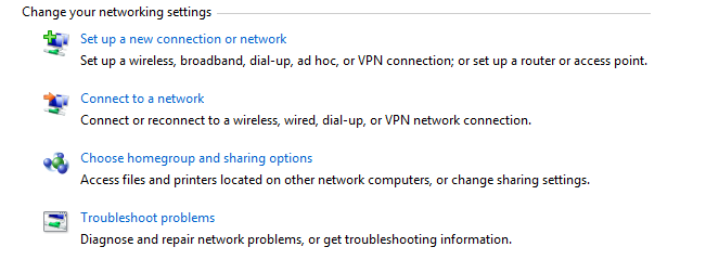
# In the Set up a Connection or Network window, select Connect to a workplace, and then click Next.
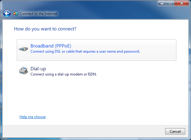
Figure 4 Connecting to the Internet
# Select the Broadband (PPPoE) option to begin configuring the connection method.
Figure 5 Using broadband (PPPoE)
# In the User name and Password fields, enter the username and password set on the PPPoE server, vpdnuser and user1234 in this example. Configure the connection name as PPPoE. Click Create.
Figure 6 Entering the configuration
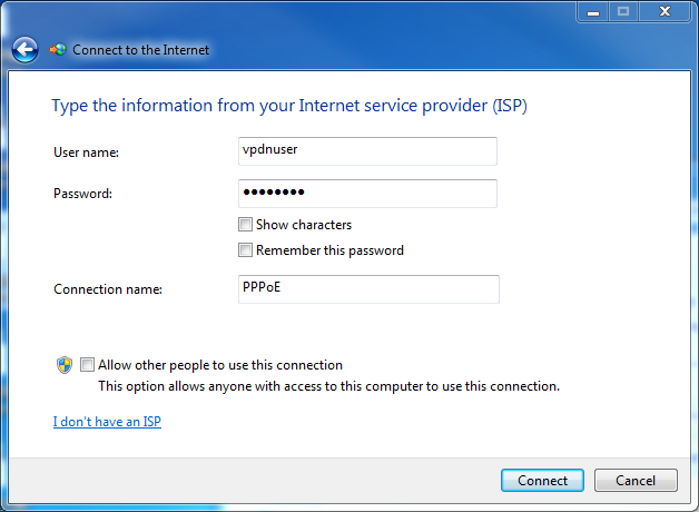
# Click Connect to complete the configuration.
Verifying the configuration
After successfully establishing the PPPoE connection, verify that Host can ping the internal network server (FTP server).
ping 192.168.2.2
Pinging 192.168.2.2 with 32 bytes of data:
Reply from 192.168.2.2: Bytes=32 time=26ms TTL=126
Reply from 192.168.2.2: Bytes=32 time<1ms TTL=128
Reply from 192.168.2.2: Bytes=32 time<1ms TTL=128
Reply from 192.168.2.2: Bytes=32 time<1ms TTL=128
Ping statistics for 192.168.2.2:
Packets Sent = 4, Received = 4, Lost = 0 (0% loss),
Approximate round trip time in milli-seconds:
Minimum = 0ms, Maximum = 26ms, Average = 6ms
Configuration files
#
sysname Router
#
dialer-group 1 rule ip permit
#
dhcp enable
#
dhcp server ip-pool pool1
gateway-list 192.168.2.1
network 192.168.2.0 mask 255.255.255.0
address range 192.168.2.2 192.168.2.254
dns-list 5.5.5.5 6.6.6.6
#
interface Dialer1
ppp chap password cipher $c$3$5GU01VyGVy/DlbWlpfuQteNoEH40zWPoIGY=
ppp chap user vpdnuser
ppp ipcp dns admit-any
ppp ipcp dns request
dialer bundle enable
dialer-group 1
dialer timer idle 0
ip address ppp-negotiate
nat outbound
#
interface GigabitEthernet0/1
port link-mode route
ip address 20.1.1.1 255.255.255.0
pppoe-client dial-bundle-number 1
#
interface GigabitEthernet0/2
port link-mode route
combo enable copper
ip address 192.168.2.1 255.255.255.0
#
ip route-static 0.0.0.0 0 Dialer1
#
