- Table of Contents
-
- 04-Network Configuration
- 01-Access Public and Dedicated Networks Through Multiple WAN Interfaces (CLI)
- 02-Basic Network Access (DHCP-Based IP Address Acquisition) Configuration Examples (CLI)
- 03-ER G3 Routers PPPoE Configuration Examples (Web)
- 04-ER G3 Routers Basic Network Access (DHCP-Based IP Address Acquisition) (Web)
- 05-ER G3 Routers Basic Internet Access (Static IP) Web-Based Configuration Examples
- 06-MER Routers Basic Network Access (DHCP-Based IP Address Acquisition) (Web)
- 07-MER Routers Primary and Backup Network Accesses Through Multiple WAN Interfaces (Web)
- 08-MER Routers PPPoE Configuration Examples (Web)
- 09-MER Routers Access Public and Dedicated Networks Through Multiple WAN Interfaces (Web)
- 10-MER Routers Basic Internet Access (Static IP) Web-Based Configuration Examples
- 11-MSR Routers Basic Network Access (DHCP-Based IP Address Acquisition) (Web)
- 12-MSR Routers Basic Internet Access (Static IP) Web-Based Configuration Examples
- 13-MSR Routers Access Public and Dedicated Networks Through Multiple WAN Interfaces (Web)
- 14-MSR Routers PPPoE Configuration Examples (CLI)
- 15-Router Basic Internet Access (Static IP) CLI-Based Configuration Examples
- Related Documents
-
| Title | Size | Download |
|---|---|---|
| 07-MER Routers Primary and Backup Network Accesses Through Multiple WAN Interfaces (Web) | 376.29 KB |
MER Routers
Primary/Backup Network Access Through Multiple WAN Interfaces (Web)
Copyright © 2024 New H3C Technologies Co., Ltd. All rights reserved.
No part of this manual may be reproduced or transmitted in any form or by any means without prior written consent of New H3C Technologies Co., Ltd.
Except for the trademarks of New H3C Technologies Co., Ltd., any trademarks that may be mentioned in this document are the property of their respective owners.
The information in this document is subject to change without notice.
Introduction
The following information describes how to configure primary/backup network access through multiple WAN interfaces.
Prerequisites
This document is not restricted to specific software or hardware versions. Procedures and information in the examples might be slightly different depending on the software or hardware version of the device.
The configuration examples were created and verified in a lab environment, and all the devices were started with the factory default configuration. When you are working on a live network, make sure you understand the potential impact of every command on your network.
The following information is provided based on the assumption that you have basic knowledge of primary/backup network access.
Software versions used
This document applies to Comware 7-based MER router series. This configuration example was created and verified on R6749P14 of the MER8300 router.
Example: Configuring primary/backup network access through multiple WAN interfaces
Network configuration
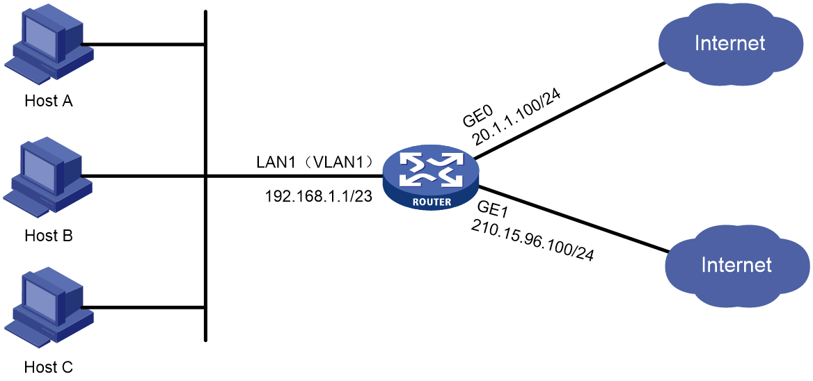
As shown in Figure 1, an enterprise leases IP address 20.1.1.100/24 with 1000 Mbps bandwidth from a service provider for Internet access. To avoid service interruption caused by service provider link failures, the enterprise leases 210.15.96.100/24 with 1000 Mbps bandwidth from another service provider for backup Internet access.
Procedures
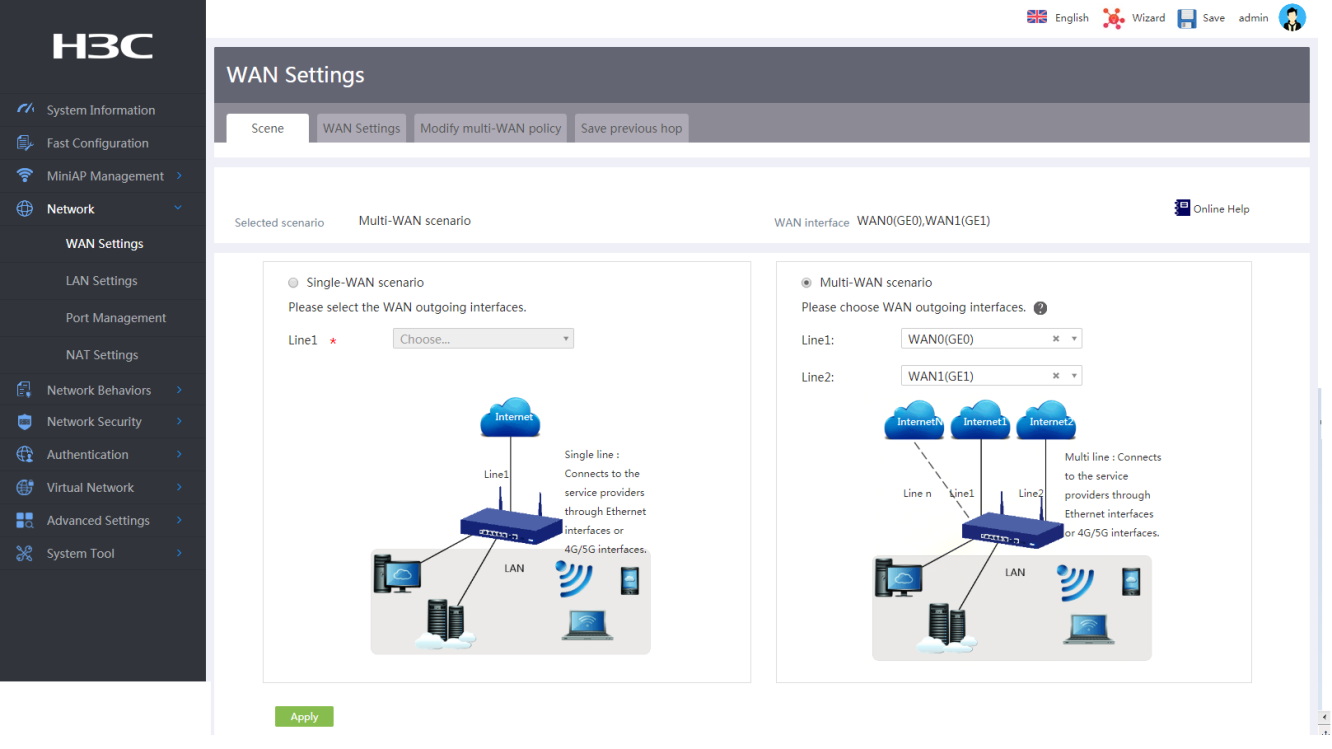
1. On the Web interface of the device, select Network > WAN Settings from the navigation pane.
2. Click the Scene tab.
3. Select the multi-WAN scenario.
4. Select interface WAN0 (GE0) for line 1 and interface WAN1 (GE1) for line 2.
5. Click Apply.
Figure 2 Configuring WAN settings
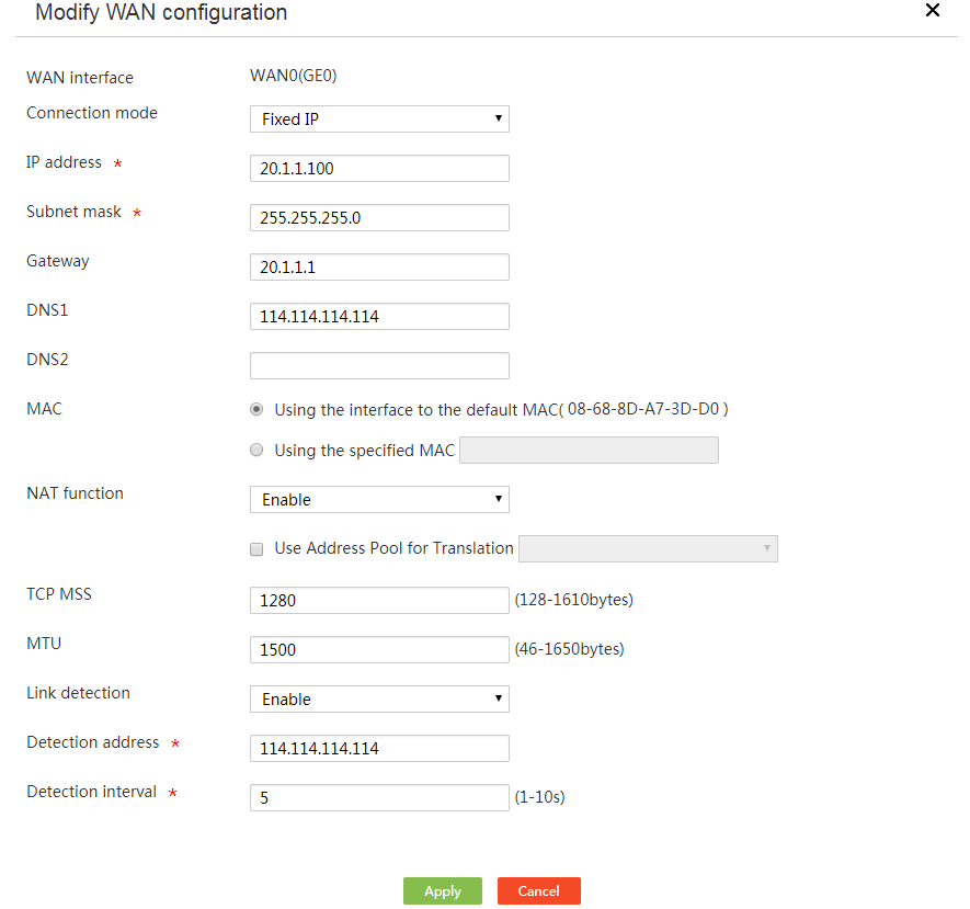
6. Click the WAN Settings tab.
7. In the interface list, click the edit icon in the actions column for line 1. The page for editing the WAN configuration opens.
8. Select the fixed IP connection mode.
9. Enter 20.1.1.100 in the IP address field.
10. Enter 255.255.255.0 in the subnet mask field.
11. Enter 20.1.1.1 in the gateway field.
12. In the DNS1 field, enter 114.114.114.114.
13. Enable NAT.
14. Enable link detection.
15. In the Detected address field, enter the IP address for link detection (114.114.114.114 ).
16. In the Detection interval field, enter the interval for link detection (5).
17. Use the default settings for the other parameters, and then click Apply.
Figure 3 Connecting interface WAN0 to the Internet
18. In the interface list, click the edit icon in the actions column for line 2. The page for editing the WAN configuration opens.
19. Select the PPPoE connection mode.
20. In the user ID field, enter the PPPoE access username provided by the service provider.
21. In the password field, enter the PPPoE access password provided by the service provider.
22. Enable NAT.
23. Enable link detection.
24. In the Detected address field, enter the IP address for link detection (114.114.114.114 ).
25. In the Detection interval field, enter the interval for link detection (5).
26. Use the default settings for the other parameters, and then click Apply.
Figure 4 Connecting interface WAN1 to the Internet

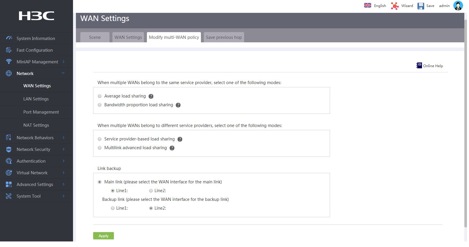
27. Click the Modify multi-WAN policy tab.
28. Select line 1 as the primary link and line 2 as the backup link.
Figure 5 Editing the multi-WAN policy
Verifying the configuration
1. Log in to the PC, set the tracert IP address to 114.114.114.114, and then view the route path.
C:\Users\abc>tracert 114.114.114.114
Tracert route 114.114.114.114 through a maximum of 30 hops
1 <1 ms 1ms 1ms erlogin.cn[192.168.1.1]
2 <1 ms <1 ms <1 20.1.1.1
3 <1 ms <1 ms <1 114.114.114.114
Tracert completed.
2. Disconnect interface WAN0, log in to the PC, set the tracert IP address to 114.114.114.114, and then view the route path.
C:\Users\abc>tracert 114.114.114.114
Tracert route 114.114.114.114 through a maximum of 30 hops
1 <1 ms 1ms 1ms erlogin.cn[192.168.1.1]
2 <1 ms <1 ms <1 210.15.96.1
3 <1 ms <1 ms <1 114.114.114.114
Tracert completed.
The output shows that WAN0 is the next hop for the PC to access the Internet when both WAN0 and WAN1 are connected correctly. When WAN0 is disconnected, the next hop for the PC to access the Internet becomes WAN1.
