- Table of Contents
-
- 04-Network Configuration
- 01-Access Public and Dedicated Networks Through Multiple WAN Interfaces (CLI)
- 02-Basic Network Access (DHCP-Based IP Address Acquisition) Configuration Examples (CLI)
- 03-ER G3 Routers PPPoE Configuration Examples (Web)
- 04-ER G3 Routers Basic Network Access (DHCP-Based IP Address Acquisition) (Web)
- 05-ER G3 Routers Basic Internet Access (Static IP) Web-Based Configuration Examples
- 06-MER Routers Basic Network Access (DHCP-Based IP Address Acquisition) (Web)
- 07-MER Routers Primary and Backup Network Accesses Through Multiple WAN Interfaces (Web)
- 08-MER Routers PPPoE Configuration Examples (Web)
- 09-MER Routers Access Public and Dedicated Networks Through Multiple WAN Interfaces (Web)
- 10-MER Routers Basic Internet Access (Static IP) Web-Based Configuration Examples
- 11-MSR Routers Basic Network Access (DHCP-Based IP Address Acquisition) (Web)
- 12-MSR Routers Basic Internet Access (Static IP) Web-Based Configuration Examples
- 13-MSR Routers Access Public and Dedicated Networks Through Multiple WAN Interfaces (Web)
- 14-MSR Routers PPPoE Configuration Examples (CLI)
- 15-Router Basic Internet Access (Static IP) CLI-Based Configuration Examples
- Related Documents
-
| Title | Size | Download |
|---|---|---|
| 08-MER Routers PPPoE Configuration Examples (Web) | 167.98 KB |
MER Routers
PPPoE Configuration Examples
Copyright © 2024 New H3C Technologies Co., Ltd. All rights reserved.
No part of this manual may be reproduced or transmitted in any form or by any means without prior written consent of New H3C Technologies Co., Ltd.
Except for the trademarks of New H3C Technologies Co., Ltd., any trademarks that may be mentioned in this document are the property of their respective owners.
The information in this document is subject to change without notice.
Introduction
The following information provides PPPoE configuration examples from the Web interface.
Prerequisites
This document is not restricted to specific software or hardware versions. Procedures and information in the examples might be slightly different depending on the software or hardware version of the device.
The configuration examples were created and verified in a lab environment, and all the devices were started with the factory default configuration. When you are working on a live network, make sure you understand the potential impact of every command on your network.
The following information is provided based on the assumption that you have basic knowledge of PPPoE.
Software version used
This configuration example was created and verified on MER8300 Release 6749P14.
Example: Configuring PPPoE on the Web interface
Network configuration
As shown in Figure 1, Host can connect to Router through PPPoE and then to the external network. Configure the network to meet the following requirements:
· Host accesses the Internet through Router.
· As a PPPoE client, Router accesses the public network through the ISP network.

Procedures
1. Select Fast Configuration.
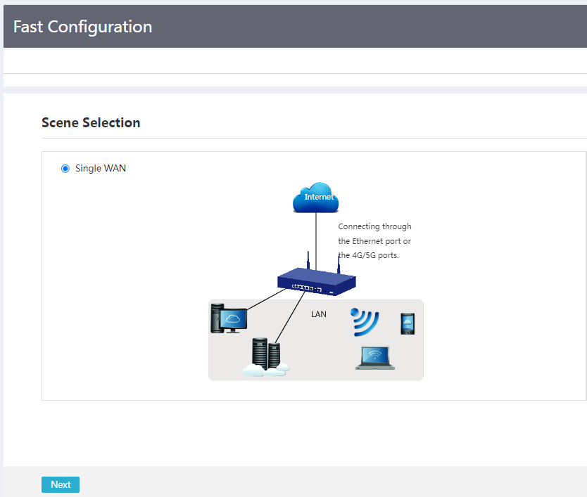
2. On the Scene Selection page, select the single-WAN scenario, and Next.
Figure 2 Selecting a scenario
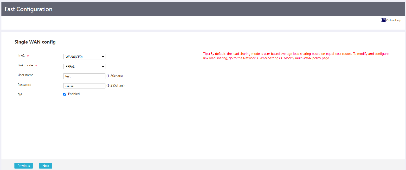
3. On the Single WAN config page, configure the following parameters:
¡ From the Line 1 list, select WAN0(GE0).
¡ From the Link Mode list, select PPPoE.
¡ In the User name field, enter a user name (test in this example).
¡ In the Password field, enter a password (test123 in this example).
¡ For the NAT field, select Enabled.
Figure 3 Single WAN config
4. Click Next to access the LAN config page.
5. On the LAN config page, configure the following parameters:
¡ In the Local IP address field, enter a LAN IP address (192.168.1.1 in this example).
¡ In the IP mask field, enter a subnet mask (255.255.255.0 in this example).
¡ For the DHCP server field, select Enabled.
¡ In the IP distribution range field, specify an IP allocation range (192.168.1.2 to 192.168.1.254 in this example).
¡ In the Gateway address field, enter a gateway IP address (192.168.1.1 in this example).
¡ In the DNS field, enter a DNS server address (8.8.8.8 in this example).
Figure 4 LAN config

6. Click Next to access the configuration check page. Verify that the configuration is correct, and then click Finish to complete the configuration.
Figure 5 Configuration completed

