- Table of Contents
-
- 04-Network Configuration
- 01-Access Public and Dedicated Networks Through Multiple WAN Interfaces (CLI)
- 02-Basic Network Access (DHCP-Based IP Address Acquisition) Configuration Examples (CLI)
- 03-ER G3 Routers PPPoE Configuration Examples (Web)
- 04-ER G3 Routers Basic Network Access (DHCP-Based IP Address Acquisition) (Web)
- 05-ER G3 Routers Basic Internet Access (Static IP) Web-Based Configuration Examples
- 06-MER Routers Basic Network Access (DHCP-Based IP Address Acquisition) (Web)
- 07-MER Routers Primary and Backup Network Accesses Through Multiple WAN Interfaces (Web)
- 08-MER Routers PPPoE Configuration Examples (Web)
- 09-MER Routers Access Public and Dedicated Networks Through Multiple WAN Interfaces (Web)
- 10-MER Routers Basic Internet Access (Static IP) Web-Based Configuration Examples
- 11-MSR Routers Basic Network Access (DHCP-Based IP Address Acquisition) (Web)
- 12-MSR Routers Basic Internet Access (Static IP) Web-Based Configuration Examples
- 13-MSR Routers Access Public and Dedicated Networks Through Multiple WAN Interfaces (Web)
- 14-MSR Routers PPPoE Configuration Examples (CLI)
- 15-Router Basic Internet Access (Static IP) CLI-Based Configuration Examples
- Related Documents
-
| Title | Size | Download |
|---|---|---|
| 09-MER Routers Access Public and Dedicated Networks Through Multiple WAN Interfaces (Web) | 681.72 KB |
MER Routers
Access Public and Dedicated Networks Through Multiple WAN Interfaces (Web)
Copyright © 2024 New H3C Technologies Co., Ltd. All rights reserved.
No part of this manual may be reproduced or transmitted in any form or by any means without prior written consent of New H3C Technologies Co., Ltd.
Except for the trademarks of New H3C Technologies Co., Ltd., any trademarks that may be mentioned in this document are the property of their respective owners.
The information in this document is subject to change without notice.
Introduction
The following information describes how to use the webpage to configure access to both a dedicated network and the public network through multiple WAN interfaces.
Prerequisites
This document is not restricted to specific software or hardware versions. Procedures and information in the examples might be slightly different depending on the software or hardware version of the device.
The configuration examples were created and verified in a lab environment, and all the devices were started with the factory default configuration. When you are working on a live network, make sure you understand the potential impact of every command on your network.
The following information is provided based on the assumption that you have basic knowledge of DHCP and NAT.
Example: Configuring access to both a dedicated network and the public network through multiple WAN interfaces
Network configuration
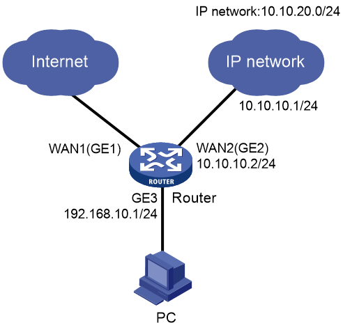
As shown in Figure 1, the device acts as the egress router of the enterprise network. Interface WAN1 (GE1) accesses the public network through DHCP, and interface WAN2 (GE2) accesses a dedicated network through a private line. Configure the following settings for the PC to access both the public and dedicated networks:
· Configure the public network segment as 10.10.10.0/24 and the private network segment as 10.10.20.0/24.
· Configure the LAN segment as 192.168.10.0/24, and configure the device to act as the DHCP server to allocate IP addresses to clients.
Software version used
This document applies to Comware 7-based MER router series. This configuration example was created and verified on R6749P14 of the MER8300 router.
Restrictions and guidelines
Make sure the address pool specified on the LAN interface does not overlap with the WAN interface IP address range specified on the device.
Procedures
Configuring WAN access
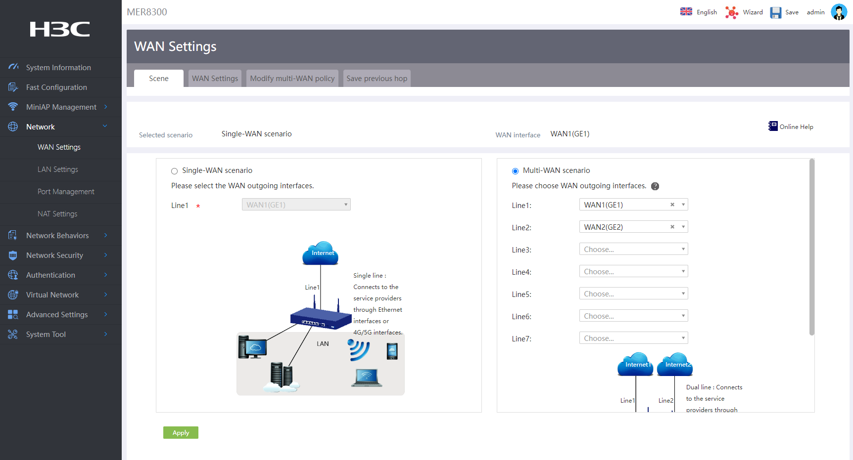
2. On the Scene tab, select the multi-WAN scenario.
3. Select interface WAN1 (GE1) for line 1 and interface WAN2 (GE2) for line 2.
4. Click Apply.
Figure 2 Configuring WAN access
Configuring interface WAN1
1. Click the WAN Settings tab.
2. Click the edit icon in the actions column for interface WAN1 (GE1).
3. Select the DHCP connection mode.
¡ In the MAC field, select to use the factory default MAC of the interface because the service provider does not specify a MAC address.
¡ Enable the NAT feature.
¡ In the TCP MSS and MTU fields, configure the MSS of TCP packets and the MTU for the interface.
4. Click Apply.
Figure 3 Editing WAN settings

Configuring interface WAN2
1. Click the edit icon in the actions column for interface WAN2 (GE2).
2. Select Fixed IP connection mode.
¡ In the IP address field, enter the IP address (10.10.10.2) for accessing the WAN.
¡ In the Subnet mask field, enter the mask (255.255.255.0) or mask length (24) for the IP address.
¡ In the Gateway field, enter the gateway address (10.10.10.1) for accessing the WAN.
¡ In the DNS1 and DNS2 fields, enter the IP addresses of DNS servers (114.114.114.114 and 8.8.8.8) for accessing the WAN.
¡ In the MAC field, select to use the factory default MAC of the interface because the service provider does not specify a MAC address.
¡ Enable the NAT feature.
¡ In the TCP MSS and MTU fields, set the MSS of TCP packets to 1280 and the MTU for the interface to 1500.
¡ In the Link detection field, enable this feature, enter the IP address for link detection (114.114.114.114) and the interval for link detection (10).
3. Click Apply.
Figure 4 Editing WAN settings

Configuring the LAN interface
1. From the navigation pane, select Network > LAN Settings.
2. On the LAN Settings tab, click Add.
3. In the LAN interface type field, select the GE interface type, and select GE3 as the interface for connecting to the private network.
4. In the Interface IP address field, enter the IP address of the interface (192.168.10.1).
5. In the Subnet mask field, enter the mask (255.255.255.0) or mask length (24) for the IP address.
6. In the TCP MSS field, set the MSS of TCP packets to 1280.
7. In the MTU field, set the MTU of the interface to 1500.
8. For the device to dynamically allocate IP addresses to clients connected to interface GE3, select Enable DHCP to enable DHCP for the device, and then configure the following settings:
¡ In the start address of pool and end address of pool fields, set the IP address range to 192.168.10.1 to 192.168.10.254.
¡ If some IP addresses in the address range (for example, the gateway address) cannot be assigned to clients, specify these addresses as excluded IP addresses. In this example, the gateway address (192.168.10.1) is excluded.
¡ In the Gateway address field, set the gateway address to 192.168.10.1.
¡ In the DNS1 and DNS2 fields, enter the IP addresses of DNS servers (114.114.114.114 and 8.8.8.8).
¡ In the Address lease field, enter the lease (in minutes) of IP addresses to be assigned. For example, to specify the lease of IP addresses as five days, enter 7200.
9. Click Apply.
Figure 5 Configuring the LAN interface

Configuring static routing
1. From the left navigation pane, select Advanced Settings > Static Routing.
2. Click Add to access the page for adding an IPv4 static route.
3. Set the destination IP address to 10.10.20.0, and set the mask length to 24.
4. Select WAN2 (GE2) as the output interface of the next hop, and set the next hop address to 10.10.10.1.
5. Click Apply.
Figure 6 Adding an IPv4 static route

Verifying the configuration
Verify that the PC can access the Internet and dedicated network successfully. (Details not shown.)
