- Table of Contents
-
- 04-Network Configuration
- 01-Access Public and Dedicated Networks Through Multiple WAN Interfaces (CLI)
- 02-Basic Network Access (DHCP-Based IP Address Acquisition) Configuration Examples (CLI)
- 03-ER G3 Routers PPPoE Configuration Examples (Web)
- 04-ER G3 Routers Basic Network Access (DHCP-Based IP Address Acquisition) (Web)
- 05-ER G3 Routers Basic Internet Access (Static IP) Web-Based Configuration Examples
- 06-MER Routers Basic Network Access (DHCP-Based IP Address Acquisition) (Web)
- 07-MER Routers Primary and Backup Network Accesses Through Multiple WAN Interfaces (Web)
- 08-MER Routers PPPoE Configuration Examples (Web)
- 09-MER Routers Access Public and Dedicated Networks Through Multiple WAN Interfaces (Web)
- 10-MER Routers Basic Internet Access (Static IP) Web-Based Configuration Examples
- 11-MSR Routers Basic Network Access (DHCP-Based IP Address Acquisition) (Web)
- 12-MSR Routers Basic Internet Access (Static IP) Web-Based Configuration Examples
- 13-MSR Routers Access Public and Dedicated Networks Through Multiple WAN Interfaces (Web)
- 14-MSR Routers PPPoE Configuration Examples (CLI)
- 15-Router Basic Internet Access (Static IP) CLI-Based Configuration Examples
- Related Documents
-
| Title | Size | Download |
|---|---|---|
| 01-Access Public and Dedicated Networks Through Multiple WAN Interfaces (CLI) | 63.34 KB |
Access Public and Dedicated Networks Through Multiple WAN Interfaces (CLI)
Copyright © 2024 New H3C Technologies Co., Ltd. All rights reserved.
No part of this manual may be reproduced or transmitted in any form or by any means without prior written consent of New H3C Technologies Co., Ltd.
Except for the trademarks of New H3C Technologies Co., Ltd., any trademarks that may be mentioned in this document are the property of their respective owners.
The information in this document is subject to change without notice.
Introduction
The following information describes how to use CLI to configure access to both a dedicated network and the public network through multiple WAN interfaces.
Prerequisites
This document is not restricted to specific software or hardware versions. Procedures and information in the examples might be slightly different depending on the software or hardware version of the device.
The configuration examples were created and verified in a lab environment, and all the devices were started with the factory default configuration. When you are working on a live network, make sure you understand the potential impact of every command on your network.
The following information is provided based on the assumption that you have basic knowledge of DHCP and NAT.
Example: Configuring access to both a dedicated network and the public network through multiple WAN interfaces
Network configuration
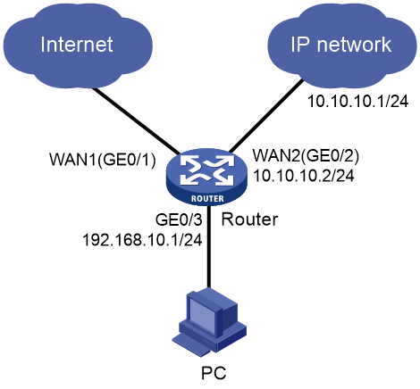
As shown in Figure 1, the device acts as the egress router of the enterprise network. Interface WAN1 (GE0/1) accesses the public network through DHCP, and interface WAN2 (GE0/2) accesses a dedicated network through a private line. Configure the following settings for the PC to access both the public and dedicated networks:
· Configure the public network segment as 10.10.10.0/24 and the private network segment as 10.10.20.0/24.
· Configure the LAN segment as 192.168.10.0/24, and configure the device to act as the DHCP server to allocate IP addresses to clients.
Restrictions and guidelines
Make sure the address pool specified on the LAN interface does not overlap with the WAN interface IP address range specified on the device.
Procedures
Configuring external network access settings
Configuring interface WAN1
# Configure interface WAN1 (GE0/1) to obtain public network addresses through DHCP.
<Router> system-view
[Router] interface gigabitethernet 0/1
[Router-GigabitEthernet0/1] ip address dhcp-alloc
# Configure outbound dynamic NAT.
[Router-GigabitEthernet0/1] nat outbound
[Router-GigabitEthernet0/1] quit
Configuring the LAN interface
# Configure interface GE0/3 as the LAN gateway.
[Router] interface gigabitethernet 0/3
[Router-GigabitEthernet0/3] ip address 192.168.10.1 24
[Router-GigabitEthernet0/3] quit
Configuring the device as the DHCP server
# Create DHCP address pool 1 and enter its view.
[Router] dhcp server ip-pool 1
# Specify subnet 192.168.10.0/24 for dynamic allocation in the address pool.
[Router-dhcp-pool-1] network 192.168.10.0 mask 255.255.255.0
# Specify gateway address 192.168.10.1 in the address pool.
[Router-dhcp-pool-1] gateway-list 192.168.10.1
# Configure 114.114.114.114 and 8.8.8.8 as the DNS server addresses.
[Router-dhcp-pool-1] dns-list 114.114.114.114 8.8.8.8
# Set the address lease to 10 days and 12 hours.
[Router-dhcp-pool-1] expired day 10 hour 12
[Router-dhcp-pool-1] quit
# Create DHCP address pool 1 and enter its view.
[Router] ip pool 1
# Specify subnet 192.168.10.0/24 for dynamic allocation in the address pool.
[Router-ip-pool-1] network 192.168.10.0 mask 255.255.255.0
# Specify gateway address 192.168.10.1 in the address pool.
[Router-ip-pool-1] gateway-list 192.168.10.1
# Configure 114.114.114.114 and 8.8.8.8 as the DNS server addresses.
[Router-ip-pool-1] dns-list 114.114.114.114 8.8.8.8
# Set the address lease to 10 days and 12 hours.
[Router-ip-pool-1] expired day 10 hour 12
[Router-ip-pool-1] quit
# Configure interface GE0/3 as the DHCP server to allocate IP addresses to clients.
[Router] interface gigabitethernet 0/3
[Router-GigabitEthernet0/3] dhcp select server
[Router-GigabitEthernet0/3] quit
Configuring dedicated network settings
# Configure interface WAN2 (GE0/2) to use a fixed address for network access.
[Router] interface gigabitethernet 0/2
[Router-GigabitEthernet0/2] ip address 10.10.10.2 24
# Configure outbound dynamic NAT.
[Router-GigabitEthernet0/2] nat outbound
[Router-GigabitEthernet0/2] quit
# Configure a static route.
[Router] ip route-static 10.10.20.0 255.255.255.0 10.10.10.1
Verifying the configuration
Verify that the PC can access the Internet and IP dedicated network successfully. (Details not shown.)
