- Table of Contents
-
- H3C S6300 Configuration Examples-6W100
- 01-Login Management Configuration Examples
- 02-RBAC Configuration Examples
- 03-Software Upgrade Configuration Examples
- 04-Software Patching Examples
- 05-ISSU Configuration Examples
- 06-Ethernet Link Aggregation Configuration Examples
- 07-Port Isolation Configuration Examples
- 08-Spanning Tree Configuration Examples
- 09-VLAN Configuration Examples
- 10-VLAN Tagging Configuration Examples
- 11-DHCP Snooping Configuration Examples
- 12-Cross-Subnet Dynamic IP Address Allocation Configuration Examples
- 13-IGMP Snooping Configuration Examples
- 14-MLD Snooping Configuration Examples
- 15-IPv6 Multicast VLAN Configuration Examples
- 16-ACL Configuration Examples
- 17-Control Plane-Based QoS Policy Configuration Examples
- 18-Traffic Policing Configuration Examples
- 19-GTS and Rate Limiting Configuration Examples
- 20-Priority and Queue Scheduling Configuration Examples
- 21-Traffic Filtering Configuration Examples
- 22-AAA Configuration Examples
- 23-Port Security Configuration Examples
- 24-Portal Configuration Examples
- 25-SSH Configuration Examples
- 26-IP Source Guard Configuration Examples
- 27-Ethernet OAM Configuration Examples
- 28-CFD Configuration Examples
- 29-DLDP Configuration Examples
- 30-FCoE Configuration Examples
- 31-NTP Configuration Examples
- 32-PTP Configuration Examples
- 33-SNMP Configuration Examples
- 34-NQA Configuration Examples
- 35-Mirroring Configuration Examples
- 36-sFlow Configuration Examples
- 37-OpenFlow Configuration Examples
- Related Documents
-
| Title | Size | Download |
|---|---|---|
| 22-AAA Configuration Examples | 238.16 KB |
|
|
|
H3C S6300 Switch Series |
|
AAA Configuration Examples |
|
|
Copyright © 2020 New H3C Technologies Co., Ltd. All rights reserved.
No part of this manual may be reproduced or transmitted in any form or by any means without prior written consent of New H3C Technologies Co., Ltd.
Except for the trademarks of New H3C Technologies Co., Ltd., any trademarks that may be mentioned in this document are the property of their respective owners.
The information in this document is subject to change without notice.
Contents
Example: Configuring HWTACACS authentication and authorization for Telnet users
Configuring the HWTACACS server
Example: Configuring RADIUS authentication and authorization for SSH users
Introduction
This document provides AAA configuration examples for Telnet and SSH users.
Prerequisites
The configuration examples in this document were created and verified in a lab environment, and all the devices were started with the factory default configuration. When you are working on a live network, make sure you understand the potential impact of every command on your network.
This document assumes that you have basic knowledge of AAA.
Example: Configuring HWTACACS authentication and authorization for Telnet users
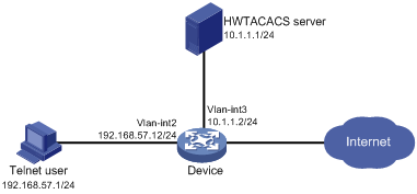
Network requirements
As shown in Figure 1, configure the device to meet the following requirements:
· The HWTACACS server is used to provide authentication and authorization services for Telnet users.
· The authenticated users are permitted to execute the display commands of all system features and resources.
Add a user account with username user@bbb and password aabbcc on the HWTACACS server.
Requirements analysis
To meet the network requirements, you must perform the following tasks:
· Configure the Telnet username and password on the HWTACACS server to identify valid users.
· For Telnet users to perform AAA, set the authentication mode to scheme on VTY user lines.
· Configure the same shared key on the device and the HWTACACS server to secure HWTACACS communication. When the shared key is configured, the device and the HWTACACS server transfer passwords safely and the device can verify the integrity of each HWTACACS response.
· Configure HWTACACS authentication and authorization by performing the following tasks on the device:
¡ Create an HWTACACS scheme.
¡ Specify the authentication and authorization servers.
¡ Apply the HWTACACS scheme to the ISP domain to which the Telnet users belong on the device.
· Assign the user role network-operator to the users, so the users can use all display commands.
Software version used
This configuration example was created and verified on S6300-CMW710-R2310.
Configuration procedures
Configuring the HWTACACS server
In this example, the server runs ACS 4.0.
Adding a user
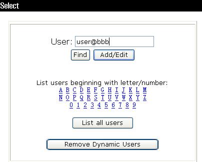
1. In the navigation tree, click User Setup.
2. Enter user@bbb in the User field and click Add/Edit, as shown in Figure 2.
Configuring the user
1. On the User Setup page, configure the following parameters, as shown in Figure 3:
¡ Enter aabbcc in the Password and Confirm Password fields.
¡ Assign the user to user group Group 1.
Figure 3 Configuring the user password
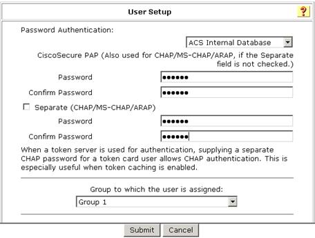
2. Click Submit.
Configuring the network settings
1. In the navigation tree, click Network Configuration.
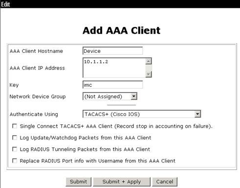
2. On the Add AAA Client page, configure the following parameters, as shown in Figure 4:
¡ Enter an AAA client hostname in the AAA Client Hostname field. This example uses Device.
¡ Enter 10.1.1.2 in the AAA Client IP Address field.
The IP address is the source IP address for outgoing HWTACACS packets on the device.
¡ Enter imc in the Key field.
The key configured here is the same as the key configured on the device for secure HWTACACS communication.
¡ Select TACACS+ (Cisco IOS) from the Authenticate Using list.
Figure 4 Configuring the network settings
3. Click Submit + Apply.
Configuring the user group
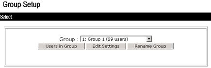
1. In the navigation tree, click Group Setup.
2. Select 1: Group 1 (29 users) from the Group list and click Edit Settings, as shown in Figure 5.
Figure 5 Selecting a user group
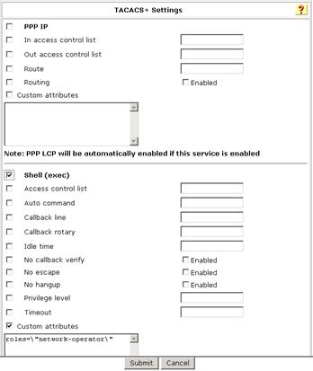
3. On the TACACS+ Settings page, configure the following parameters, as shown in Figure 6:
¡ Select Shell(exec), which enables command execution for all users in the group.
¡ Select Custom attributes, and enter roles=\"network-operator\" in the Custom attributes field.
The network-operator user role has access to the display commands of all system features and resources.
¡ Configure other settings as needed.
Figure 6 Configuring the user group
4. Click Submit.
Configuring the device
# Create VLAN 2 and assign Ten-GigabitEthernet 1/0/2 to the VLAN.
[Device] vlan 2
[Device-vlan2] port ten-gigabitethernet 1/0/2
[Device-vlan2] quit
# Assign an IP address to VLAN-interface 2.
[Device] interface vlan-interface 2
[Device-Vlan-interface2] ip address 192.168.57.12 255.255.255.0
[Device-Vlan-interface2] quit
# Create VLAN 3 and assign Ten-GigabitEthernet 1/0/1 to the VLAN.
[Device] vlan 3
[Device-vlan3] port ten-gigabitethernet 1/0/1
[Device-vlan3] quit
# Assign an IP address to VLAN-interface 3. The device will use this IP address as the source IP address for outgoing HWTACACS packets.
[Device] interface vlan-interface 3
[Device-Vlan-interface3] ip address 10.1.1.2 255.255.255.0
[Device-Vlan-interface3] quit
# Enable the Telnet server feature.
[Device] telnet server enable
# Enable scheme authentication on VTY user lines 0 through 63.
[Device] line vty 0 63
[Device-line-vty0-63] authentication-mode scheme
[Device-line-vty0-63] quit
# Create HWTACACS scheme hwtac.
[Device] hwtacacs scheme hwtac
# Specify the primary HWTACACS server with the IP address 10.1.1.1 and port number 49.
[Device-hwtacacs-hwtac] primary authentication 10.1.1.1 49
[Device-hwtacacs-hwtac] primary authorization 10.1.1.1 49
[Device-hwtacacs-hwtac] primary accounting 10.1.1.1 49
# Specify the shared key as imc for secure HWTACACS communication between the device and HWTACACS server.
[Device-hwtacacs-hwtac] key authentication simple imc
[Device-hwtacacs-hwtac] key authorization simple imc
[Device-hwtacacs-hwtac] key accounting simple imc
[Device-hwtacacs-hwtac] quit
# Create ISP domain bbb, and specify the domain to use HWTACACS scheme hwtac as the AAA methods of login users.
[Device] domain bbb
[Device-isp-bbb] authentication login hwtacacs-scheme hwtac
[Device-isp-bbb] authorization login hwtacacs-scheme hwtac
[Device-isp-bbb] accounting login hwtacacs-scheme hwtac
[Device-isp-bbb] quit
Verifying the configuration
# Telnet to the device, and enter the username user@bbb and password aabbcc. The user logs in to the device. (Details not shown.)
# Verify that the user can use the display commands of all system features and resources. (Details not shown.)
Configuration files
#
telnet server enable
#
vlan 2 to 3
#
interface Vlan-interface2
ip address 192.168.57.12 255.255.255.0
#
interface Vlan-interface3
ip address 10.1.1.2 255.255.255.0
#
interface Ten-GigabitEthernet1/0/2
port access vlan 2
#
interface Ten-GigabitEthernet1/0/1
port access vlan 3
#
line vty 0 63
authentication-mode scheme
user-role network-operator
#
hwtacacs scheme hwtac
primary authentication 10.1.1.1
primary authorization 10.1.1.1
primary accounting 10.1.1.1
key authentication cipher $c$3$6ps2/dT38b2K2MDCMCDGYxrvyJNR+/jiKw==
key authorization cipher $c$3$xEldxJraE8Yof3rHHlVIgyCIb/uLlrZbgg==
key accounting cipher $c$3$kySCJbNA8DSs+l3HCqxunl8SE4me3vue5g==
#
domain bbb
authentication login hwtacacs-scheme hwtac
authorization login hwtacacs-scheme hwtac
accounting login hwtacacs-scheme hwtac
#
Example: Configuring RADIUS authentication and authorization for SSH users
Network requirements
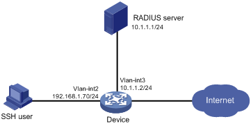
As shown in Figure 7, configure the device to meet the following requirements:
· The RADIUS server is used to provide authentication and authorization services for SSH users.
· Domain names are included in the usernames sent to the RADIUS server.
· The authenticated users are permitted to use the display commands of all system features and resources.
IMC is the RADIUS server. Add a user account with username hello@bbb and password aabbcc on the server.
Requirements analysis
To meet the network requirements, you must perform the following tasks:
· Configure the SSH username and password on the RADIUS server to identify valid users.
· For SSH users to perform AAA, set the authentication mode to scheme on VTY user lines.
· Configure the same shared key on the device and the RADIUS server to secure RADIUS communication. When the shared key is configured, the device and the RADIUS server transfer passwords safely and the device can verify the integrity of each RADIUS response.
· Configure RADIUS authentication and authorization by performing the following tasks on the device:
¡ Create a RADIUS scheme.
¡ Specify the authentication and authorization servers.
¡ Apply the RADIUS scheme to the ISP domain to which the SSH users belong on the device.
· Assign the user role network-operator to the users, so the users can use all display commands.
Software version used
This configuration example was created and verified on S6300-CMW710-R2310.
Configuration procedures
Configuring the RADIUS server
In this example, the server runs IMC PLAT 7.0 (E0102) and IMC UAM 7.0 (E0201).
Adding the device to IMC as an access device
1. Click the User tab.
2. From the navigation tree, select User Access Policy > Access Device Management > Access Device.
The access device list appears.
3. Click Add.
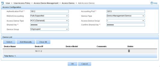
4. On the Add Access Device page, configure the following parameters, as shown in Figure 8:
¡ Enter 1812 and 1813 in the Authentication Port and Accounting Port fields, respectively.
¡ Enter expert in the Shared Key and Confirm Shared Key fields.
¡ Select Device Management Service from the Service Type list.
¡ Select H3C(General) from the Access Device Type list.
¡ Use the default values for other parameters in the Access Configuration area.
¡ In the Device List area, click Select or Add Manually to add the device (10.1.1.2) to IMC as an access device.
Figure 8 Adding an access device
5. Click OK.
Adding a device management user
1. Click the User tab.
2. From the navigation tree, select Access User > Device User.
The device management user list appears.
3. Click Add.
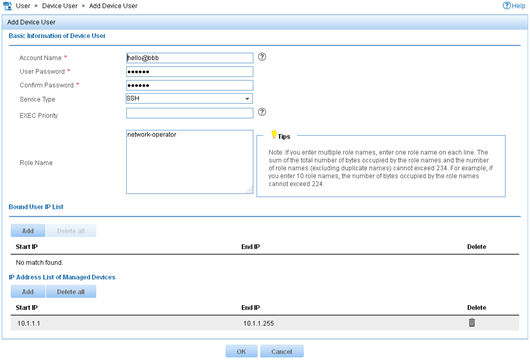
4. On the Add Device User page, configure the following parameters, as shown in Figure 9:
¡ Enter hello@bbb in the Account Name field.
¡ Enter aabbcc in the User Password and Confirm Password fields.
¡ Select SSH from the Service Type list.
¡ Enter network-operator in the Role Name field.
The network-operator user role has access to the display commands of all system features and resources.
¡ In the IP Address List of Managed Devices area, click Add to specify an IP segment (from 10.1.1.0 to 10.1.1.255) for management. The IP segment must contain the IP address of the access device.
Figure 9 Adding a device management user
5. Click OK.
Configuring the device
# Create VLAN 2 and assign Ten-GigabitEthernet 1/0/2 to the VLAN.
<Device> system-view
[Device] vlan 2
[Device-vlan2] port ten-gigabitethernet 1/0/2
[Device-vlan2] quit
# Assign an IP address to VLAN-interface 2.
[Device] interface vlan-interface 2
[Device-Vlan-interface2] ip address 192.168.1.70 255.255.255.0
[Device-Vlan-interface2] quit
# Create VLAN 3 and assign Ten-GigabitEthernet 1/0/1 to the VLAN.
[Device] vlan 3
[Device-vlan3] port ten-gigabitethernet 1/0/1
[Device-vlan3] quit
# Assign an IP address to VLAN-interface 3.
[Device] interface vlan-interface 3
[Device-Vlan-interface3] ip address 10.1.1.2 255.255.255.0
[Device-Vlan-interface3] quit
# Generate RSA and DSA key pairs.
[Device] public-key local create rsa
The range of public key size is (512 ~ 2048).
If the key modulus is greater than 512, it will take a few minutes.
Press CTRL+C to abort.
Input the modulus length [default = 1024]:
Generating Keys...
........................++++++
...................++++++
..++++++++
............++++++++
Create the key pair successfully.
[Device] public-key local create dsa
The range of public key size is (512 ~ 2048).
If the key modulus is greater than 512, it will take a few minutes.
Press CTRL+C to abort.
Input the modulus length [default = 1024]:
Generating Keys...
.++++++++++++++++++++++++++++++++++++++++++++++++++*
........+......+.....+......................................+
...+.................+..........+...+.
Create the key pair successfully.
# Enable the SSH server feature.
[Device] ssh server enable
# Enable scheme authentication on VTY user lines 0 through 63.
[Device] line vty 0 63
[Device-line-vty0-63] authentication-mode scheme
[Device-line-vty0-63] quit
# Create RADIUS scheme rad.
[Device] radius scheme rad
# Specify the primary authentication RADIUS server with the IP address 10.1.1.1 and port number 1812.
[Device-radius-rad] primary authentication 10.1.1.1 1812
# Specify the primary accounting RADIUS server with the IP address 10.1.1.1 and port number 1813.
[Device-radius-rad] primary accounting 10.1.1.1 1813
# Set the authentication and accounting shared keys to expert in plain text for secure communication between the device and the RADIUS server.
[Device-radius-rad] key authentication simple expert
[Device-radius-rad] key accounting simple expert
# Include domain names in the usernames sent to the RADIUS server.
[Device-radius-rad] user-name-format with-domain
[Device-radius-rad] quit
# Create ISP domain bbb, and configure the ISP domain to use RADIUS scheme rad as the AAA methods of login users.
[Device] domain bbb
[Device-isp-bbb] authentication login radius-scheme rad
[Device-isp-bbb] authorization login radius-scheme rad
[Device-isp-bbb] accounting login radius-scheme rad
[Device-isp-bbb] quit
Verifying the configuration
# Initiate an SSH connection to the device, and enter the username hello@bbb and password aabbcc. The user logs in to the device. (Details not shown.)
# Verify that the user can use the display commands of all system features and resources. (Details not shown.)
Configuration files
#
vlan 2 to 3
#
interface Vlan-interface2
ip address 192.168.1.70 255.255.255.0
#
interface Vlan-interface3
ip address 10.1.1.2 255.255.255.0
#
interface Ten-GigabitEthernet1/0/2
port access vlan 2
#
interface Ten-GigabitEthernet1/0/1
port access vlan 3
#
line vty 0 63
authentication-mode scheme
user-role network-operator
#
ssh server enable
#
radius scheme rad
primary authentication 10.1.1.1
primary accounting 10.1.1.1
key authentication cipher $c$3$63G7LzIQElGq4aFGTiYQafU+loQxS/cbLg==
key accounting cipher $c$3$tUIVlyGISJ5X/yiTFWrmh8nyjBIF+1LFzQ==
#
domain bbb
authentication login radius-scheme rad
authorization login radius-scheme rad
accounting login radius-scheme rad
#
Related documentation
· H3C S6300 Switch Series Security Configuration Guide-Release 23xx
· H3C S6300 Switch Series Security Command Reference-Release 23xx