- Table of Contents
-
- 07-IP Multicast Configuration Guide
- 00-Preface
- 01-Multicast Overview
- 02-IGMP Snooping Configuration
- 03-PIM Snooping Configuration
- 04-Multicast VLAN Configuration
- 05-Multicast Routing and Forwarding Configuration
- 06-IGMP Configuration
- 07-PIM Configuration
- 08-MSDP Configuration
- 09-MBGP Configuration
- 10-Multicast VPN Configuration
- 11-MLD Snooping Configuration
- 12-IPv6 PIM Snooping Configuration
- 13-IPv6 Multicast VLAN Configuration
- 14-IPv6 Multicast Routing and Forwarding Configuration
- 15-MLD Configuration
- 16-IPv6 PIM Configuration
- 17-IPv6 MBGP Configuration
- Related Documents
-
| Title | Size | Download |
|---|---|---|
| 05-Multicast Routing and Forwarding Configuration | 405.27 KB |
Contents
Configuring multicast routing and forwarding
Multicast routing and forwarding overview
GRE tunnel application in multicast forwarding
Configuring multicast routing and forwarding
Configuring static multicast routes
Configuring a multicast routing policy
Configuring a multicast forwarding range
Configuring the multicast forwarding table size
Configuring RPF check failure processing
Displaying and maintaining multicast routing and forwarding
Multicast forwarding over GRE tunnels
Troubleshooting multicast routing and forwarding
Static multicast route failure
Multicast data fails to reach receivers
Multicast routing and forwarding overview
In multicast implementations, multicast routing and forwarding are implemented by three types of tables:
· Each multicast routing protocol has its own multicast routing table, such as PIM routing table.
· The information of different multicast routing protocols forms a general multicast routing table.
· The multicast forwarding table is directly used to control the forwarding of multicast packets.
A multicast forwarding table consists of a set of (S, G) entries, each indicating the routing information for delivering multicast data from a multicast source to a multicast group. If a router supports multiple multicast protocols, its multicast routing table will include routes generated by multiple protocols. The router chooses the optimal route from the multicast routing table based on the configured multicast routing and forwarding policy and installs the route entry into its multicast forwarding table.
RPF check mechanism
A multicast routing protocol relies on the existing unicast routing information, MBGP routes, or static multicast routes in creating multicast routing entries. When creating multicast routing table entries, a multicast routing protocol uses the reverse path forwarding (RPF) check mechanism to ensure multicast data delivery along the correct path. In addition, the RPF check mechanism also helps avoid data loops caused by various reasons.
RPF check
The basis for an RPF check is a unicast route, an MBGP route, or a static multicast route.
· A unicast routing table contains the shortest path to each destination subnet.
· An MBGP routing table contains multicast routing information.
· A multicast static routing table contains the RPF routing information defined by the user through static configuration.
When performing an RPF check, a router searches its unicast routing table and multicast static routing table at the same time. The specific process is as follows:
1. The router first chooses an optimal route from the unicast routing table, MBGP routing table, and multicast static routing table:
¡ The router automatically chooses an optimal unicast route by searching its unicast routing table, using the IP address of the “packet source” as the destination address. The outgoing interface in the corresponding routing entry is the RPF interface and the next hop is the RPF neighbor. The router considers the path along which the packet from the RPF neighbor arrived on the RPF interface to be the shortest path that leads back to the source.
¡ The router automatically chooses an optimal MBGP route by searching its MBGP routing table, using the IP address of the “packet source” as the destination address. The outgoing interface in the corresponding routing entry is the RPF interface and the next hop is the RPF neighbor.
¡ The router automatically chooses an optimal static multicast route by searching its multicast static routing table, using the IP address of the “packet source” as the source address. The corresponding routing entry explicitly defines the RPF interface and the RPF neighbor.
2. Then, the router selects one from these three optimal routes as the RPF route. The selection process is as follows:
¡ If configured to use the longest match principle, the router selects the longest match route from the three. If these three routes have the same mask, the router selects the route with the highest priority. If the three routes have the same priority, the router selects the RPF route according to the sequence of static multicast route, MBGP route, and unicast route.
¡ If not configured to use the longest match principle, the router selects the route with the highest priority. If the three routes have the same priority, the router selects the RPF route according to the sequence of static multicast route, MBGP route, and unicast route.
|
|
NOTE: The above-mentioned “packet source” can mean different things in different situations: · For a packet traveling along the shortest path tree (SPT) from the multicast source to the receivers or the rendezvous point (RP), the “packet source” for RPF check is the multicast source. · For a packet traveling along the rendezvous point tree (RPT) from the RP to the receivers, or along the source-side RPT from the multicast source to the RP, the “packet source” for RPF check is the RP. · For a bootstrap message from the bootstrap router (BSR), the “packet source” for RPF check is the BSR. For more information about the concepts of SPT, RPT, source-side RPT, RP, and BSR, see the chapter “Configuring PIM.” |
Implementation of RPF check in multicast forwarding
Implementing an RPF check on each received multicast data packet would bring a big burden to the router. The use of a multicast forwarding table is the solution to this issue. When creating a multicast routing entry and a multicast forwarding entry for a multicast packet, the router sets the RPF interface of the packet as the incoming interface of the (S, G) entry. Upon receiving an (S, G) multicast packet, the router first searches its multicast forwarding table:
1. If the corresponding (S, G) entry does not exist in the multicast forwarding table, the packet is subject to an RPF check. The router creates a multicast routing entry based on the relevant routing information and installs the entry into the multicast forwarding table, with the RPF interface as the incoming interface.
¡ If the interface that received the packet is the RPF interface, the RPF check succeeds and the router forwards the packet to all the outgoing interfaces.
¡ If the interface that received the packet is not the RPF interface, the RPF check fails and the router discards the packet.
2. If the corresponding (S, G) entry exists, and the interface that received the packet is the incoming interface, the router forwards the packet to all the outgoing interfaces.
3. If the corresponding (S, G) entry exists, but the interface that received the packet is not the incoming interface in the multicast forwarding table, the multicast packet is subject to an RPF check.
¡ If the RPF interface is the incoming interface of the (S, G) entry, this means the (S, G) entry is correct but the packet arrived from a wrong path. The packet is to be discarded.
¡ If the RPF interface is not the incoming interface, this means the (S, G) entry has expired, and router replaces the incoming interface with the RPF interface. If the interface on which the packet arrived in the RPF interface, the router forwards the packet to all the outgoing interfaces; otherwise it discards the packet.
|
|
CAUTION: You can configure special processing of packets that have failed an RPF check instead of simply dropping them. For more information, see “Configuring RPF check failure processing.” |
Assume that unicast routes are available in the network, MBGP is not enabled, and no static multicast routes have been configured on Router C, as shown in Figure 1. Multicast packets travel along the SPT from the multicast source to the receivers. The multicast forwarding table on Router C contains the (S, G) entry, with POS 5/1/1 as the RPF interface.
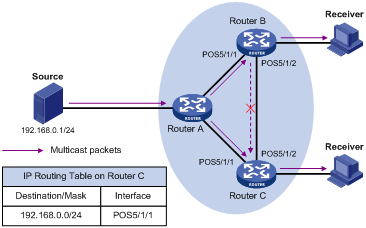
· When a multicast packet arrives on POS 5/1/1 of Router C, as the interface is the incoming interface of the (S, G) entry, the router forwards the packet to all outgoing interfaces.
· When a multicast packet arrives on POS 5/1/2 of Router C, as the interface is not the incoming interface of the (S, G) entry, the router performs an RPF check on the packet: The router searches its unicast routing table and finds that the outgoing interface to Source (the RPF interface) is POS 5/1/1. This means the (S, G) entry is correct and packet arrived along a wrong path. The RPF check fails and the packet is discarded.
Static multicast routes
A static multicast route is an important basis for RPF checks. Depending on the application environment, a static multicast route has the following functions:
Changing an RPF route
Typically, the topology structure of a multicast network is the same as that of a unicast network, and multicast traffic follows the same transmission path as unicast traffic does. By configuring a static multicast route for a given multicast source, you can change the RPF route so as to create a transmission path for multicast traffic different from that for unicast traffic.
Figure 2 Changing an RPF route
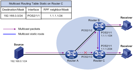
As shown in Figure 2, when no static multicast route is configured, Router C’s RPF neighbor on the path back to Source is Router A and the multicast information from Source travels along the path from Router A to Router C, which is the unicast route between the two routers; with a static route configured on Router C and Router B as Router C’s RPF neighbor on the path back to Source, the multicast information from Source travels from Router A to Router B and then to Router C.
Creating an RPF route
When a unicast route is blocked, multicast traffic forwarding is stopped due to lack of an RPF route. By configuring a static multicast route for a given multicast source, you can create an RPF route so that a multicast routing entry is created to guide multicast traffic forwarding.
Figure 3 Creating an RPF route
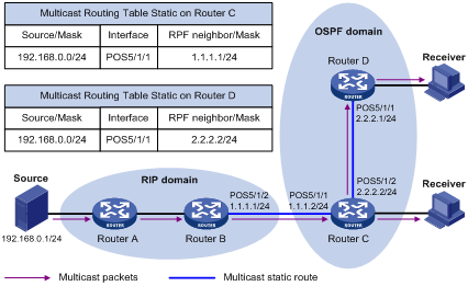
As shown in Figure 3, the RIP domain and the OSPF domain are unicast isolated from each other. When no static multicast route is configured, the hosts (Receivers) in the OSPF domain cannot receive the multicast packets sent by the multicast source (Source) in the RIP domain. After you configure a static multicast route on Router C and Router D, specifying Router B as the RPF neighbor of Router C and specifying Router C as the RPF neighbor of Router D, the receivers can receive multicast data sent by the multicast source.
|
|
NOTE: · A static multicast route only affects RPF checks; it cannot guide multicast forwarding. Therefore, a static multicast route is also called an RPF static route. · A static multicast route is effective only on the multicast router on which it is configured, and will not be advertised throughout the network or redistributed to other routers. |
GRE tunnel application in multicast forwarding
There may be routers that do not support multicast protocols in a network. As multicast traffic from a multicast source is forwarded hop by hop by multicast routers along the forwarding tree, when the multicast traffic is forwarded to a next-hop router that does not support IP multicast, the forwarding path is blocked. In this case, you can enable multicast traffic forwarding across the unicast subnet where the non-multicast-capable router resides by establishing a generic routing encapsulation (GRE) tunnel between the routers at both ends of the unicast subnet.
For more information about GRE tunneling, see Layer 3—IP Services Configuration Guide.
Figure 4 Multicast data transmission through a GRE tunnel

As shown in Figure 4, with a GRE tunnel established between Router A and Router B, Router A encapsulates multicast data in unicast IP packets, which are then forwarded by unicast routers to Router B across the GRE tunnel. Then, Router B strips off the unicast IP header and continues forwarding the multicast data down towards the receivers.
If unicast static routes are configured across the tunnel, any unicast packet can be transmitted through the tunnel. If you wish the tunnel to be dedicated to multicast traffic delivery, you can configure only a static multicast route across the tunnel, so that unicast packets cannot be transmitted through this tunnel.
Multicast traceroute
The multicast traceroute utility is used to trace the path that a multicast stream flows down from the first-hop router to the last-hop router.
Concepts in multicast traceroute
· Last-hop router—If a router has one of its interfaces connecting to the subnet the given destination address is on, and if the router is able to forward multicast streams from the given multicast source onto that subnet, that router is called last-hop router.
· First-hop router—The router that directly connects to the multicast source.
· Querier—The router requesting the multicast traceroute.
Introduction to multicast traceroute packets
A multicast traceroute packet is a special IGMP packet, which differs from common IGMP packets in that its IGMP Type field is set to 0x1F or 0x1E and that its destination IP address is a unicast address. There are three types of multicast traceroute packets:
· Query, with the IGMP Type field set to 0x1F.
· Request, with the IGMP Type field set to 0x1F.
· Response, with the IGMP Type field set to 0x1E.
Process of multicast traceroute
1. The querier sends a query to the last-hop router.
2. Upon receiving the query, the last-hop router turns the query packet into a request packet by adding a response data block containing its interface addresses and packet statistics to the end of the packet, and forwards the request packet via unicast to the previous hop for the given multicast source and group.
3. From the last-hop router to the multicast source, each hop adds a response data block to the end of the request packet and unicasts it to the previous hop.
4. When the first-hop router receives the request packet, it changes the packet type to indicate a response packet, and then sends the completed packet via unicast to the multicast traceroute querier.
Configuration task list
Complete these tasks to configure multicast routing and forwarding:
|
Task |
Remarks |
|
|
Required |
||
|
Optional |
||
|
Optional |
||
|
Optional |
||
|
Optional |
||
|
Optional |
||
|
Optional |
||
|
|
CAUTION: IP multicast does not support the use of secondary IP address segments. Namely, multicast can be routed and forwarded only through primary IP addresses, rather than secondary addresses, even if configured on interfaces. For more information about primary and secondary IP addresses, see Layer 3—IP Services Configuration Guide. |
Enabling IP multicast routing
Before configuring any Layer 3 multicast functionality, you must enable IP multicast routing.
Enabling IP multicast routing on the public network
To enable IP multicast routing on the public network:
|
Step |
Command |
Remarks |
|
1. Enter system view. |
system-view |
N/A |
|
2. Enable IP multicast routing. |
multicast routing-enable |
Disabled by default |
Enabling IP multicast routing in a VPN instance
To enable IP multicast routing in a VPN instance:
|
Step |
Command |
Remarks |
|
1. Enter system view. |
system-view |
N/A |
|
2. Create a VPN instance and enter VPN instance view. |
ip vpn-instance vpn-instance-name |
N/A |
|
3. Configure a route distinguisher (RD) for the VPN instance. |
route-distinguisher route-distinguisher |
No RD is configured by default. |
|
4. Enable IP multicast routing. |
multicast routing-enable |
Disabled by default. |
|
|
NOTE: For more information about the ip vpn-instance and route-distinguisher commands, see MPLS Command Reference. |
Configuring multicast routing and forwarding
Configuration prerequisites
Before configuring multicast routing and forwarding, complete the following tasks:
· Configure a unicast routing protocol so that all devices in the domain are interoperable at the network layer.
· Enable PIM (PIM-DM or PIM-SM).
· Determine the minimum TTL value required for a multicast packet to be forwarded.
· Determine the maximum number of downstream nodes for a single multicast forwarding table entry.
· Determine the maximum number of entries in the multicast forwarding table.
Configuring static multicast routes
By configuring a static multicast route for a given multicast source, you can specify an RPF interface or an RPF neighbor for multicast traffic from that source.
To configure a static multicast route:
|
Step |
Command |
Remarks |
|
1. Enter system view. |
system-view |
N/A |
|
2. Configure a static multicast route. |
ip rpf-route-static [ vpn-instance vpn-instance-name ] source-address { mask | mask-length } [ protocol [ process-id ] ] [ route-policy policy-name ] { rpf-nbr-address | interface-type interface-number } [ preference preference ] [ order order-number ] |
No static multicast route is configured by default. |
|
3. Delete static multicast routes. |
delete ip rpf-route-static [ vpn-instance vpn-instance-name ] |
Optional. |
|
|
CAUTION: When you configure a static multicast route, you cannot specify an RPF neighbor by providing the type and number (interface-type interface-number) of the interface that connects the RPF neighbor if the interface of the RPF neighbor is a Layer 3 Ethernet interface, Layer 3 aggregate interface, Loopback interface, Layer 3 RPR logical interface, or VLAN interface. Instead, you can specify such an RPF neighbor only by its address (rpf-nbr-address). |
Configuring a multicast routing policy
You can configure the router to select an RPF route based on the longest match principle. For more information about RPF route selection, see “RPF check.”
By configuring per-source or per-source-and-group load splitting, you can optimize the traffic delivery when multiple data flows are handled.
Configuring a multicast routing policy on the public network
To configure a multicast routing policy on the public network:
|
Step |
Command |
Remarks |
|
1. Enter system view. |
system-view |
N/A |
|
2. Configure the device to select an RPF route based on the longest match. |
multicast longest-match |
The route with the highest priority is selected as the RPF route by default |
|
3. Configuring multicast load splitting. |
multicast load-splitting { source | source-group } |
Optional. Disabled by default. |
Configuring a multicast routing policy in a VPN instance
To configure a multicast routing policy in a VPN instance:
|
Step |
Command |
Remarks |
|
1. Enter system view. |
system-view |
N/A |
|
2. Enter VPN instance view. |
ip vpn-instance vpn-instance-name |
N/A |
|
3. Configure the device to select an RPF route based on the longest match. |
multicast longest-match |
The route with the highest priority is selected as the RPF route by default. |
|
4. Configure multicast load splitting. |
multicast load-splitting { source | source-group } |
Optional. Disabled by default. |
Configuring a multicast forwarding range
Multicast packets do not travel without a boundary in a network. The multicast data corresponding to each multicast group must be transmitted within a definite scope. Presently, you can define a multicast forwarding range by specifying boundary interfaces, which form a closed multicast forwarding area.
You can configure a forwarding boundary specific to a particular multicast group on all interfaces that support multicast forwarding. A multicast forwarding boundary sets the boundary condition for the multicast groups in the specified range. If the destination address of a multicast packet matches the set boundary condition, the packet will not be forwarded. Once a multicast boundary is configured on an interface, this interface can no longer forward multicast packets (including packets sent from the local device) or receive multicast packets.
To configure a multicast forwarding range:
|
Step |
Command |
Remarks |
|
1. Enter system view. |
system-view |
N/A |
|
2. Enter interface view. |
interface interface-type interface-number |
N/A |
|
3. Configure a multicast forwarding boundary. |
multicast boundary group-address { mask | mask-length } |
No forwarding boundary by default |
Configuring the multicast forwarding table size
The router maintains the corresponding forwarding entries for each multicast data packet it receives. Excessive multicast routing entries, however, can exhaust the router’s memory and thus result in lower router performance. You can set a limit on the number of entries in the multicast forwarding table based on the actual networking situation and the performance requirements.
If the configured maximum number of multicast forwarding entries is smaller than the current value, the forwarding entries in excess will not be deleted immediately; instead they will be deleted by the multicast routing protocol running on the router. The router will no longer add new multicast forwarding entries until the number of existing multicast forwarding entries comes down below the configured value.
When forwarding multicast traffic, the router replicates a copy of the multicast traffic for each downstream node and forwards the traffic, so each of these downstream nodes forms a branch of the multicast distribution tree. You can configure the maximum number of downstream nodes (namely, the maximum number of outgoing interfaces) for a single entry in the multicast forwarding table to lessen burden on the router for replicating multicast traffic. If the configured maximum number of downstream nodes for a single multicast forwarding entry is smaller than the current number, the downstream nodes in excess will not be deleted immediately; instead they will be deleted by the multicast routing protocol. The router will no longer add new multicast forwarding entries for newly added downstream nodes until the number of existing downstream nodes comes down below the configured value.
Configuring the multicast forwarding table size on the public network
To configure the multicast forwarding table size on the public network:
|
Step |
Command |
Remarks |
|
1. Enter system view. |
system-view |
N/A |
|
2. Configure the maximum number of forwarding entries in the multicast forwarding table. |
multicast forwarding-table route-limit limit |
Optional 13824 by default |
|
3. Configure the maximum number of downstream nodes for a single multicast forwarding entry. |
multicast forwarding-table downstream-limit limit |
Optional 128 by default |
Configuring the multicast forwarding table size in a VPN instance
To configure the multicast forwarding table size in a VPN instance:
|
Step |
Command |
Remarks |
|
1. Enter system view. |
system-view |
N/A |
|
2. Enter VPN instance view. |
ip vpn-instance vpn-instance-name |
N/A |
|
3. Configure the maximum number of forwarding entries in the multicast forwarding table. |
multicast forwarding-table route-limit limit |
13824 by default |
|
4. Configure the maximum number of downstream nodes for a single multicast forwarding entry. |
multicast forwarding-table downstream-limit limit |
Optional 128 by default |
Configuring RPF check failure processing
Multicast data packets that have failed an RPF check may need to be processed differently in different networking environments instead of being simply dropped.
Enabling forwarding packets that have failed an RPF check in a VLAN or all VLANs
In practice, a multicast packet that failed RPF check on a VLAN interface might be expected by some receivers in the VLAN. You can enable forwarding such multicast packets through multicast or flooding in the VLAN so that the receivers can receive them.
With this feature enabled, the router searches its multicast forwarding table upon receiving a packet that failed RPF check. If a match is found, it multicasts the packet according to the matching entry. Otherwise, the router floods the packet in the VLAN.
To enable this feature, you also need to enable the multicast programs-on-demand function.
To enable flooding packets that have failed an RPF check in a VLAN or all VLANs:
|
Step |
Command |
Remarks |
|
1. Enter system view. |
system-view |
N/A |
|
2. Enable forwarding packets that have failed an RPF check in the VLAN or all VLANs. |
multicast rpf-fail-pkt bridging |
Disabled by default |
|
3. Enter VLAN view. |
vlan vlan-id |
N/A |
|
4. Enable the multicast programs-on-demand function in the VLAN. |
multicast forwarding on-demand |
Disabled by default |
|
|
CAUTION: · After the configuration, use the reset multicast forwarding-table command to clear all the forwarding entries in the multicast forwarding table. Otherwise this configuration cannot take effect. · If the VLAN enabled with the multicast programs-on-demand function is a multicast VLAN, you need to use the reset igmp-snooping group command to clear all the IGMP snooping multicast group information in the VLAN. Otherwise this configuration cannot take effect. For more information about the reset igmp-snooping group command, see IP Multicast Command Reference. · If the VLAN enabled with the multicast programs-on-demand function is not a multicast VLAN, and a Layer 3 multicast routing protocol (such as IGMP or PIM) has been configured on the corresponding VLAN interface, you need to use the reset igmp group port-info command to clear Layer 2 port information for all IGMP multicast groups in the VLAN and use the reset igmp group command clear all IGMP multicast group information on the corresponding VLAN interface. Otherwise this configuration cannot take effect. For more information about the reset igmp group port-info and reset igmp group commands, see IP Multicast Command Reference. · If the VLAN enabled with the multicast programs-on-demand function is not a multicast VLAN but has IGMP snooping enabled, this configuration cannot take effect. |
Enabling sending packets that have failed an RPF check to the CPU
In the following two cases, a multicast packet that failed the RPF check needs to be passed to the CPU:
· When a multicast packet arrives on an outgoing interface of the corresponding multicast forwarding entry, the packet will fail the RPF check and needs to be sent to the CPU in order to trigger the assert mechanism to prune the unwanted branch.
· If the SPT and RPT have different incoming interfaces on the receiver-side DR (the designated router), the multicast traffic will fail the RPF check on the SPT incoming interface during an RPT-to-SPT switchover before the RPF information is refreshed. If the RPT is pruned at this moment, the multicast service will be instantaneously interrupted. By passing packets that failed the RPF check on a non-outgoing interface to the CPU, the router can determine whether the packets that have failed the RPF check on the SPT interface are expected. If they are, the router initiates an RPT prune.
For more information about the assert mechanism, DR, and RPT-to-SPT switchover, see the chapter “Configuring PIM.”
To enable sending packets that have failed an RPF check to the CPU:
|
Step |
Command |
Remarks |
|
1. Enter system view. |
system-view |
N/A |
|
2. Enable sending packets that have failed an RPF check to the CPU. |
multicast rpf-fail-pkt trap-to-cpu |
Disabled by default |
|
|
CAUTION: After the configuration, use the reset multicast forwarding-table command to clear all the forwarding entries in the multicast forwarding table; otherwise this configuration cannot take effect. |
Tracing a multicast path
You can run the mtracert command to trace the path down which the multicast traffic flows from the first-hop router to the last-hop router.
To trace a multicast path:
|
Task |
Command |
Remarks |
|
Trace a multicast path. |
mtracert source-address [ [ last-hop-router-address ] group-address ] |
Available in any view |
Displaying and maintaining multicast routing and forwarding
|
Task |
Command |
Remarks |
|
View the multicast boundary information. |
display multicast [ all-instance | vpn-instance vpn-instance-name ] boundary [ group-address [ mask | mask-length ] ] [ interface interface-type interface-number ] [ | { begin | exclude | include } regular-expression ] |
Available in any view |
|
View the multicast forwarding table information. |
display multicast [ all-instance | vpn-instance vpn-instance-name ] forwarding-table [ source-address [ mask { mask | mask-length } ] | group-address [ mask { mask | mask-length } ] | incoming-interface { interface-type interface-number | register } | outgoing-interface { { exclude | include | match } { interface-type interface-number | register } } | statistics | slot slot-number ] * [ port-info ] [ | { begin | exclude | include } regular-expression ] |
Available in any view |
|
Display the DF information of the multicast forwarding table. |
display multicast [ all-instance | vpn-instance vpn-instance-name ] forwarding-table df-info [ rp-address ] [ slot slot-number ] [ | { begin | exclude | include } regular-expression ] |
Available in any view |
|
View the multicast routing table information. |
display multicast [ all-instance | vpn-instance vpn-instance-name ] routing-table [ source-address [ mask { mask | mask-length } ] | group-address [ mask { mask | mask-length } ] | incoming-interface { interface-type interface-number | register } | outgoing-interface { { exclude | include | match } { interface-type interface-number | register } } ] * [ | { begin | exclude | include } regular-expression ] |
Available in any view |
|
View the information of the multicast static routing table. |
display multicast routing-table [ all-instance | vpn-instance vpn-instance-name ] static [ source-address { mask-length | mask } ] [ | { begin | exclude | include } regular-expression ] |
Available in any view |
|
View the RPF route information of the specified multicast source. |
display multicast [ all-instance | vpn-instance vpn-instance-name ] rpf-info source-address [ group-address ] [ | { begin | exclude | include } regular-expression ] |
Available in any view |
|
Clear forwarding entries from the multicast forwarding table. |
reset multicast [ all-instance | vpn-instance vpn-instance-name ] forwarding-table { { source-address [ mask { mask | mask-length } ] | group-address [ mask { mask | mask-length } ] | incoming-interface { interface-type interface-number | register } } * | all } |
Available in user view |
|
Clear routing entries from the multicast routing table. |
reset multicast [ all-instance | vpn-instance vpn-instance-name ] routing-table { { source-address [ mask { mask | mask-length } ] | group-address [ mask { mask | mask-length } ] | incoming-interface { interface-type interface-number | register } } * | all } |
Available in user view |
|
|
NOTE: For more information about designated forwarder (DF), see the chapter “Configuring PIM.” |
|
|
CAUTION: · The reset command clears the information in the multicast routing table or the multicast forwarding table, and thus may cause failure of multicast transmission. · When a routing entry is deleted from the multicast routing table, the corresponding forwarding entry will also be deleted from the multicast forwarding table. · When a forwarding entry is deleted from the multicast forwarding table, the corresponding route entry will also be deleted from the multicast routing table. |
Configuration examples
Changing an RPF route
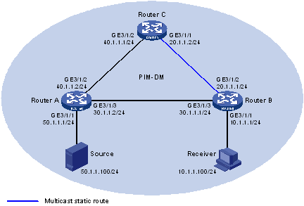
Network requirements
PIM-DM runs in the network. All routers in the network support multicast. Router A, Router B and Router C run OSPF. Typically, Receiver can receive the multicast data from Source through the path: Router A to Router B, which is the same as the unicast route.
Perform the following configuration so that Receiver can receive the multicast data from Source through the path: Router A to Router C to Router B, which is different from the unicast route.
Configuration procedure
1. Configure IP addresses and unicast routing:
Configure the IP address and subnet mask for each interface as per Figure 5. (Details not shown)
Enable OSPF on the routers in the PIM-DM domain. Ensure the network-layer interoperation among the routers in the PIM-DM domain. Make sure that the routers can dynamically update their routing information by leveraging the unicast routing protocol. (Details not shown)
2. Enable IP multicast routing, and enable PIM-DM and IGMP:
# Enable IP multicast routing on Router B, enable PIM-DM on each interface, and enable IGMP on the host-side interface GigabitEthernet 3/1/1.
<RouterB> system-view
[RouterB] multicast routing-enable
[RouterB] interface GigabitEthernet 3/1/1
[RouterB-GigabitEthernet3/1/1] igmp enable
[RouterB-GigabitEthernet3/1/1] pim dm
[RouterB-GigabitEthernet3/1/1] quit
[RouterB] interface GigabitEthernet 3/1/2
[RouterB-GigabitEthernet3/1/2] pim dm
[RouterB-GigabitEthernet3/1/2] quit
[RouterB] interface GigabitEthernet 3/1/3
[RouterB-GigabitEthernet3/1/3] pim dm
[RouterB- GigabitEthernet3/1/3] quit
# Enable IP multicast routing on Router A, and enable PIM-DM on each interface.
<RouterA> system-view
[RouterA] multicast routing-enable
[RouterA] interface GigabitEthernet 3/1/1
[RouterA-GigabitEthernet3/1/1] pim dm
[RouterA-GigabitEthernet3/1/1] quit
[RouterA] interface GigabitEthernet 3/1/2
[RouterA-GigabitEthernet3/1/2] pim dm
[RouterA-GigabitEthernet3/1/2] quit
[RouterA] interface GigabitEthernet 3/1/3
[RouterA-GigabitEthernet3/1/3] pim dm
[RouterA-GigabitEthernet3/1/3] quit
The configuration on Router C is similar to the configuration on Router A. (Details not shown)
# Use the display multicast rpf-info command to view the RPF route to Source on Router B.
[RouterB] display multicast rpf-info 50.1.1.100
RPF information about source 50.1.1.100:
VPN instance: public net
RPF interface: GigabitEthernet3/1/3, RPF neighbor: 30.1.1.2
Referenced route/mask: 50.1.1.0/24
Referenced route type: igp
Route selection rule: preference-preferred
Load splitting rule: disable
The output shows that the current RPF route on Router B is contributed by a unicast routing protocol and the RPF neighbor is Router A.
3. Configure a static multicast route:
# Configure a static multicast route on Router B, specifying Router C as its RPF neighbor to Source.
[RouterB] ip rpf-route-static 50.1.1.100 24 20.1.1.2
4. Verify the configuration:
# Use the display multicast rpf-info command to view the information about the RPF route to Source on Router B.
[RouterB] display multicast rpf-info 50.1.1.100
RPF information about source 50.1.1.100:
VPN instance: public net
RPF interface: GigabitEthernet3/1/1, RPF neighbor: 20.1.1.2
Referenced route/mask: 50.1.1.0/24
Referenced route type: multicast static
Route selection rule: preference-preferred
Load splitting rule: disable
The output shows that the RPF route on Router B has changed. It is now the configured static multicast route, and the RPF neighbor is now Router C.
Creating an RPF route
Network requirements
PIM-DM runs in the network and all routers in the network support IP multicast. Router B and Router C run OSPF, and have no unicast routes to Router A. Typically, Receiver can receive the multicast data from Source 1 in the OSPF domain.
Perform the following configuration so that Receiver can receive multicast data from Source 2, which is outside the OSPF domain.
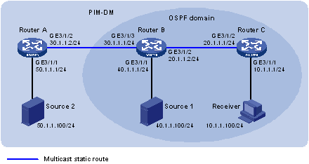
Configuration procedure
1. Configure IP addresses and unicast routing:
Configure the IP address and subnet mask for each interface as per Figure 6. (Details not shown)
Enable OSPF on Router B and Router C. Ensure the network-layer interoperation among Router B and Router C. Make sure that the routers can dynamically update their routing information by leveraging the unicast routing protocol. (Details not shown)
2. Enable IP multicast routing, and enable PIM-DM and IGMP on each interface:
# Enable IP multicast routing on Router C, enable PIM-DM on each interface, and enable IGMP on the host-side interface GigabitEthernet 3/1/1.
<RouterC> system-view
[RouterC] multicast routing-enable
[RouterC] interface GigabitEthernet 3/1/1
[RouterC-GigabitEthernet3/1/1] igmp enable
[RouterC-GigabitEthernet3/1/1] pim dm
[RouterC-GigabitEthernet] quit
[RouterC] interface GigabitEthernet 3/1/2
[RouterC-GigabitEthernet3/1/2] pim dm
[RouterC-GigabitEthernet3/1/2] quit
# Enable IP multicast routing on Router A and enable PIM-DM on each interface.
<RouterA> system-view
[RouterA] multicast routing-enable
[RouterA] interface GigabitEthernet 3/1/1
[RouterA-GigabitEthernet3/1/1] pim dm
[RouterA-GigabitEthernet3/1/1] quit
[RouterA] interface GigabitEthernet 3/1/2
[RouterA-GigabitEthernet3/1/2] pim dm
[RouterA-GigabitEthernet3/1/2] quit
The configuration on Router B is similar to that on Router A. (Details not shown)
# Use the display multicast rpf-info command to view the information of the RPF route to Source 2 on Router B and Router C.
[RouterB] display multicast rpf-info 50.1.1.100
[RouterC] display multicast rpf-info 50.1.1.100
No information is displayed. This means that no RPF route to Source 2 exists on Router B and Router C.
3. Configure a static multicast route:
# Configure a static multicast route on Router B, specifying Router A as its RPF neighbor on the route to Source 2.
[RouterB] ip rpf-route-static 50.1.1.100 24 30.1.1.2
# Configure a static multicast route on Router C, specifying Router B as its RPF neighbor on the route to Source 2.
[RouterC] ip rpf-route-static 50.1.1.100 24 20.1.1.2
4. Verify the configuration:
# Use the display multicast rpf-info command to view the RPF routes to Source 2 on Router B and Router C.
[RouterB] display multicast rpf-info 50.1.1.100
RPF information about source 50.1.1.100:
VPN instance: public net
RPF interface: GigabitEthernet3/1/3, RPF neighbor: 30.1.1.2
Referenced route/mask: 50.1.1.0/24
Referenced route type: multicast static
Route selection rule: preference-preferred
Load splitting rule: disable
[RouterC] display multicast rpf-info 50.1.1.100
RPF information about source 50.1.1.100:
VPN instance: public net
RPF interface: GigabitEthernet3/1/2, RPF neighbor: 20.1.1.2
Referenced route/mask: 50.1.1.0/24
Referenced route type: multicast static
Route selection rule: preference-preferred
Load splitting rule: disable
The output shows that the RPF routes to Source 2 exist on Router B and Router C. The source is the configured static route.
Multicast forwarding over GRE tunnels
Network requirements
Multicast routing and PIM-DM are enabled on Router A and Router C. Router B does not support multicast. OSPF is running on Router A, Router B, and Router C.
Configure a GRE tunnel so that Receiver can receive the multicast data from Source.
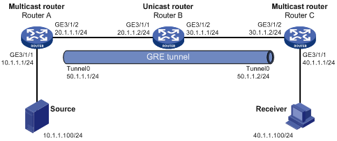
Configuration procedure
1. Configure IP addresses:
Configure the IP address and mask for each interface as per Figure 7. (Details not shown)
2. Configure a GRE tunnel:
# Create Tunnel 0 on Router A and configure the IP address and mask for the interface.
<RouterA> system-view
[RouterA] interface tunnel 0
[RouterA-Tunnel0] ip address 50.1.1.1 24
# Configure Tunnel 0 to work in the GRE tunnel mode and specify the source and destination addresses of the interface.
[RouterA-Tunnel0] tunnel-protocol gre
[RouterA-Tunnel0] source 20.1.1.1
[RouterA-Tunnel0] destination 30.1.1.2
[RouterA-Tunnel0] quit
# Create Tunnel 0 on Router C and configure the IP address and mask for the interface.
<RouterC> system-view
[RouterC] interface tunnel 0
[RouterC-Tunnel0] ip address 50.1.1.2 24
# Configure Tunnel to operate in the GRE tunnel mode and configure the source and destination addresses of the interface.
[RouterC-Tunnel0] tunnel-protocol gre
[RouterC-Tunnel0] source 30.1.1.2
[RouterC-Tunnel0] destination 20.1.1.1
[RouterC-Tunnel0] quit
3. Configure OSPF:
# Configure OSPF on Router A.
[RouterA] ospf 1
[RouterA-ospf-1] area 0
[RouterA-ospf-1-area-0.0.0.0] network 10.1.1.0 0.0.0.255
[RouterA-ospf-1-area-0.0.0.0] network 20.1.1.0 0.0.0.255
[RouterA-ospf-1-area-0.0.0.0] network 50.1.1.0 0.0.0.255
[RouterA-ospf-1-area-0.0.0.0] quit
[RouterA-ospf-1] quit
# Configure OSPF on Router B.
<RouterB> system-view
[RouterB] ospf 1
[RouterB-ospf-1] area 0
[RouterB-ospf-1-area-0.0.0.0] network 20.1.1.0 0.0.0.255
[RouterB-ospf-1-area-0.0.0.0] network 30.1.1.0 0.0.0.255
[RouterB-ospf-1-area-0.0.0.0] quit
[RouterB-ospf-1] quit
# Configure OSPF on Router C.
[RouterC] ospf 1
[RouterC-ospf-1] area 0
[RouterC-ospf-1-area-0.0.0.0] network 30.1.1.0 0.0.0.255
[RouterC-ospf-1-area-0.0.0.0] network 40.1.1.0 0.0.0.255
[RouterC-ospf-1-area-0.0.0.0] network 50.1.1.0 0.0.0.255
[RouterC-ospf-1-area-0.0.0.0] quit
[RouterC-ospf-1] quit
4. Enable IP multicast routing, PIM-DM, and IGMP:
# Enable multicast routing on Router A and enable PIM-DM on each interface.
[RouterA] multicast routing-enable
[RouterA] interface GigabitEthernet 3/1/1
[RouterA-GigabitEthernet3/1/1] pim dm
[RouterA-GigabitEthernet3/1/1] quit
[RouterA] interface GigabitEthernet 3/1/2
[RouterA-GigabitEthernet3/1/2] pim dm
[RouterA-GigabitEthernet3/1/2] quit
[RouterA] interface tunnel 0
[RouterA-Tunnel0] pim dm
[RouterA-Tunnel0] quit
# Enable multicast routing on Router C, enable PIM-DM on each interface, and enable IGMP on GigabitEthernet 3/1/1.
[RouterC] multicast routing-enable
[RouterC] interface GigabitEthernet 3/1/1
[RouterC-GigabitEthernet3/1/1] igmp enable
[RouterC-GigabitEthernet3/1/1] pim dm
[RouterC-GigabitEthernet3/1/1] quit
[RouterC] interface GigabitEthernet 3/1/2
[RouterC-GigabitEthernet3/1/2] pim dm
[RouterC-GigabitEthernet3/1/2] quit
[RouterC] interface tunnel 0
[RouterC-Tunnel0] pim dm
[RouterC-Tunnel0] quit
5. Configure a static multicast route:
# On Router C, configure a static multicast route and specify its RPF neighbor leading toward Source is Tunnel 0 on Router A.
[RouterC] ip rpf-route-static 10.1.1.0 24 50.1.1.1
6. Verify the configuration:
Source sends multicast data to the multicast group 225.1.1.1 and Receiver can receive the multicast data after joining the multicast group. You can view the PIM routing table information on routers using the display pim routing-table command. For example:
# View the PIM routing table information on Router C.
[RouterC] display pim routing-table
VPN-Instance: public net
Total 1 (*, G) entry; 1 (S, G) entry
(*, 225.1.1.1)
Protocol: pim-dm, Flag: WC
UpTime: 00:04:25
Upstream interface: NULL
Upstream neighbor: NULL
RPF prime neighbor: NULL
Downstream interface(s) information:
Total number of downstreams: 1
1: GigabitEthernet3/1/1
Protocol: igmp, UpTime: 00:04:25, Expires: never
(10.1.1.100, 225.1.1.1)
Protocol: pim-dm, Flag: ACT
UpTime: 00:06:14
Upstream interface: Tunnel0
Upstream neighbor: 50.1.1.1
RPF prime neighbor: 50.1.1.1
Downstream interface(s) information:
Total number of downstreams: 1
1: GigabitEthernet3/1/1
Protocol: pim-dm, UpTime: 00:04:25, Expires: never
The output shows that Router A is the RPF neighbor of Router C and the multicast data from Router A is delivered over a GRE tunnel to Router C.
Troubleshooting multicast routing and forwarding
Static multicast route failure
Symptom
No dynamic routing protocol is enabled on the routers, and the physic status and link layer status of interfaces are both up, but the static multicast route fails.
Analysis
· If the static multicast route is not configured or updated correctly to match the current network conditions, the route entry and the configuration information of static multicast routes do not exist in the multicast routing table.
· If a better route is found, the static multicast route may also fail.
Solution
1. Use the display multicast routing-table static command to view information about static multicast routes to verify that the static multicast route has been correctly configured and that the route entry exists in the multicast routing table.
2. Check the type of next hop interface type of the static multicast route. If the interface is not a point-to-point interface, be sure to specify the next hop address for the outgoing interface when you configure the static multicast route.
3. Check that the static multicast route matches the specified routing protocol. If a protocol was specified in static multicast route configuration, use the display ip routing-table command to verify that an identical route was added by the protocol.
4. Check that the static multicast route matches the specified routing policy. If a routing policy was specified when the static multicast route was configured, use the display route-policy command to check the configured routing policy.
Multicast data fails to reach receivers
Symptom
The multicast data can reach some routers but fails to reach the last hop router.
Analysis
If a multicast forwarding boundary has been configured through the multicast boundary command, any multicast packet will be kept from crossing the boundary.
Solution
1. Use the display pim routing-table command to check whether the corresponding (S, G) entries exist on the router. If so, the router has received the multicast data; otherwise, the router has not received the data.
2. Use the display multicast boundary command to view the multicast boundary information on the interfaces. Use the multicast boundary command to change the multicast forwarding boundary setting.
3. In the case of PIM-SM, use the display current-configuration command to check the BSR and RP information.