- Table of Contents
-
- 07-IP Multicast Configuration Guide
- 00-Preface
- 01-Multicast Overview
- 02-IGMP Snooping Configuration
- 03-PIM Snooping Configuration
- 04-Multicast VLAN Configuration
- 05-Multicast Routing and Forwarding Configuration
- 06-IGMP Configuration
- 07-PIM Configuration
- 08-MSDP Configuration
- 09-MBGP Configuration
- 10-Multicast VPN Configuration
- 11-MLD Snooping Configuration
- 12-IPv6 PIM Snooping Configuration
- 13-IPv6 Multicast VLAN Configuration
- 14-IPv6 Multicast Routing and Forwarding Configuration
- 15-MLD Configuration
- 16-IPv6 PIM Configuration
- 17-IPv6 MBGP Configuration
- Related Documents
-
| Title | Size | Download |
|---|---|---|
| 02-IGMP Snooping Configuration | 469.6 KB |
Contents
Basic concepts in IGMP snooping
IGMP snooping configuration task list
Configuring basic IGMP snooping functions
Configuring the version of IGMP snooping
Configuring the maximum number of global IGMP forwarding entries
Configuring IGMP snooping port functions
Configuring aging timers for dynamic ports
Configuring a port as a simulated member host
Configuring fast-leave processing
Disabling a port from becoming a dynamic router port
Configuring IGMP snooping querier
Enabling IGMP snooping querier
Configuring IGMP queries and responses
Configuring source IP address of IGMP queries
Configuring IGMP snooping proxying
Enabling IGMP snooping proxying
Configuring a source IP address for the IGMP messages sent by the proxy
Configuring an IGMP snooping policy
Configuring a multicast group filter
Configuring the function of dropping unknown multicast data
Configuring IGMP report suppression
Setting the maximum number of multicast groups that a port can join
Configuring multicast group replacement
Enabling the IGMP snooping host tracking function
Displaying and maintaining IGMP snooping
IGMP snooping configuration examples
Configuring group filtering and simulated joining
IGMP snooping querier configuration
IGMP snooping proxying configuration example
Layer 2 multicast forwarding cannot function
Configured multicast group policy fails to take effect
Processing of multicast protocol messages
IGMP snooping overview
Internet Group Management Protocol (IGMP) snooping is a multicast constraining mechanism that runs on Layer 2 devices to manage and control multicast groups.
By analyzing received IGMP messages, an IGMP snooping–enabled Layer 2 device establishes mappings between ports and multicast MAC addresses and forwards multicast data based on these mappings.
As shown in Figure 1, when IGMP snooping is not running on the device, multicast packets are broadcast to all devices at Layer 2. When IGMP snooping runs on the device, multicast packets for known multicast groups are multicast to the receivers, rather than broadcast to all hosts, at Layer 2.
Figure 1 Before and after IGMP snooping is enabled on the Layer 2 device
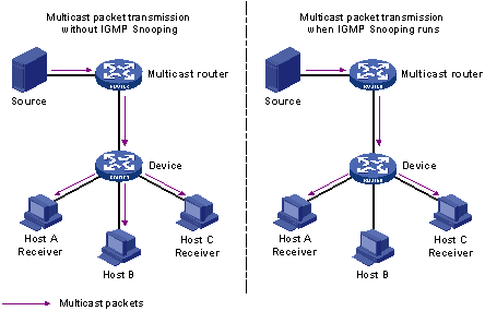
IGMP snooping forwards multicast data to only the receivers requiring the data at Layer 2. It has the following advantages:
· Reducing Layer 2 broadcast packets, thus saving network bandwidth
· Enhancing the security of multicast traffic
· Facilitating the implementation of per-host accounting
Basic concepts in IGMP snooping
IGMP snooping related ports
As shown in Figure 2, Router A connects to the multicast source, IGMP snooping runs on Device A and Device B, Host A and Host C are receiver hosts (namely, multicast group members).
Figure 2 IGMP snooping related ports
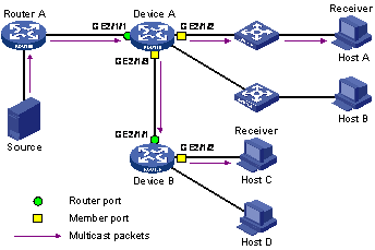
Ports involved in IGMP snooping, as shown in Figure 2, are described as follows:
· Router port—A router port is a port on the device that leads device towards the Layer 3 multicast device (DR or IGMP querier). In the figure, GigabitEthernet 2/1/1 of Device A and GigabitEthernet 2/1/1 of Device B are router ports. The device registers all its local router ports in its router port list.
· Member port—A member port is a port on the device that leads device towards multicast group members. In the figure, GigabitEthernet 2/1/2 and GigabitEthernet 2/1/3 of Device A and GigabitEthernet 2/1/2 of Device B are member ports. The device registers all the member ports on the local device in its IGMP snooping forwarding table.
|
|
NOTE: · In this document, a router port is a port on the device that leads the device to a Layer 3 multicast device, rather than a port on a router. · Unless otherwise specified, router/member ports mentioned in this document include static and dynamic ports. · An IGMP snooping–enabled device deems that all its ports on which IGMP general queries with the source IP address other than 0.0.0.0 or PIM hello messages are received to be dynamic router ports. For more information about PIM hello messages, see the chapter “Configuring PIM.” |
Aging timers for dynamic ports in IGMP snooping and related messages and actions
Table 1 Aging timers for dynamic ports in IGMP snooping and related messages and actions
|
Timer |
Description |
Message before expiry |
Action after expiry |
|
Dynamic router port aging timer |
For each dynamic router port, the device sets a timer initialized to the dynamic router port aging time. |
IGMP general query of which the source address is not 0.0.0.0 or PIM hello |
The device removes this port from its router port list. |
|
Dynamic member port aging timer |
When a port dynamically joins a multicast group, the device sets a timer for the port, which is initialized to the dynamic member port aging time. |
IGMP membership report |
The device removes this port from the IGMP snooping forwarding table. |
|
|
NOTE: The port aging mechanism of IGMP snooping works only for dynamic ports; a static port will never age out. |
How IGMP snooping works
An IGMP snooping–enabled device performs different actions when it receives different IGMP messages, as follows:
|
|
CAUTION: The description about adding or deleting a port in this section is only for a dynamic port. Static ports can be added or deleted only through the corresponding configurations. For more information, see “Configuring static ports.” |
When receiving a general query
The IGMP querier periodically sends IGMP general queries to all hosts and routers (224.0.0.1) on the local subnet to find out whether active multicast group members exist on the subnet.
After receiving an IGMP general query, the device forwards it through all ports in the VLAN (except the port that received the query). The device also performs the following judgment:
· If the receiving port is a dynamic router port in the router port list, the device resets the aging timer of this dynamic router port.
· If the receiving port is not a dynamic router port in the router port list, the device adds it into its router port list and sets an aging timer for this dynamic router port.
When receiving a membership report
A host sends an IGMP report to the IGMP querier in the following circumstances:
· Upon receiving an IGMP query, a multicast group member host responds with an IGMP report.
· When intended to join a multicast group, a host sends an IGMP report to the IGMP querier to announce that it is interested in the multicast information addressed to that group.
After receiving an IGMP report, the device forwards it through all the router ports in the VLAN, resolves the address of the reported multicast group. The device also performs the following judgment:
· If no forwarding table entry exists for the reported group, the device creates an entry, adds the port as a dynamic member port to the outgoing port list, and starts a member port aging timer for that port.
· If a forwarding table entry exists for the reported group, but the port is not included in the outgoing port list for that group, the device adds the port as a dynamic member port to the outgoing port list, and starts an aging timer for that port.
· If a forwarding table entry exists for the reported group and the port is included in the outgoing port list, which means that this port is already a dynamic member port, the device resets the aging timer for that port.
|
|
NOTE: A device does not forward an IGMP report through a non-router port. The reason is that if the device forwards a report message through a member port, all the attached hosts that are monitoring the reported multicast address suppress their own reports after receiving this report according to the IGMP report suppression mechanism. This prevents the device from determining whether the reported multicast group still has active members attached to that port. For more information about the IGMP report suppression mechanism, see the chapter “Configuring IGMP.” |
When receiving a leave message
When an IGMPv1 host leaves a multicast group, the host does not send an IGMP leave message, so the device cannot know immediately that the host has left the multicast group. However, as the host stops sending IGMP reports as soon as it leaves a multicast group, the device deletes the forwarding entry for the dynamic member port that corresponds to the host from the forwarding table when its aging timer expires.
When an IGMPv2 or IGMPv3 host leaves a multicast group, the host sends an IGMP leave message to the multicast router.
When the device hears a group-specific IGMP leave message on a dynamic member port, it first checks whether a forwarding table entry for that group exists, and, if one exists, whether its outgoing port list contains that port.
· If the forwarding table entry does not exist or its outgoing port list does not contain the port, the device discards the IGMP leave message instead of forwarding it to any port.
· If the forwarding table entry exists and its outgoing port list contains the port, the device forwards the leave message to all router ports in the VLAN. Because the device does not know whether any other hosts attached to the port are still listening to that group address, the device does not immediately remove the port from the outgoing port list of the forwarding table entry for that group; instead, it resets the aging timer for the port.
After receiving the IGMP leave message from a host, the IGMP querier resolves from the message the address of the multicast group that the host just left and sends an IGMP group-specific query to that multicast group through the port that received the leave message. Upon hearing the IGMP group-specific query, the device forwards it through all its router ports in the VLAN and all member ports for that multicast group. The device also performs the following judgment on the port that received the IGMP leave message:
· If the port (a dynamic member port supposed) receives any IGMP report in response to the group-specific query before its aging timer expires, it indicates that a host attached to the port is receiving or expecting to receive multicast data for that multicast group. The device resets the aging timer of the port.
· If the port receives no IGMP report in response to the group-specific query before its aging timer expires, it indicates that no hosts attached to the port are still monitoring that group address. The device removes the port from the outgoing port list of the entry in the forwarding table for that multicast group when the aging timer expires.
IGMP snooping proxying
You can configure the IGMP snooping proxying function on an edge device to reduce the number of IGMP reports and leave messages sent to its upstream device. The device configured with IGMP snooping proxying is called an IGMP snooping proxy. It is a host from the perspective of its upstream device.
|
|
NOTE: Even though an IGMP snooping proxy is a host from the perspective of its upstream device, the IGMP membership report suppression mechanism for hosts does not take effect on it. For more information about the IGMP report suppression mechanism for hosts, see the chapter “Configuring IGMP.” |
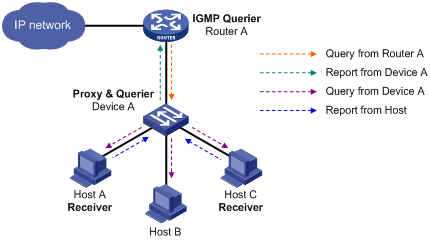
As shown in Figure 3, Device A works as an IGMP snooping proxy. As a host from the perspective of the querier Router A, Device A represents its attached hosts to send membership reports and leave messages to Router A.
Table 2 describes how an IGMP snooping proxy processes IGMP messages.
Table 2 IGMP message processing on an IGMP snooping proxy
|
IGMP message |
Actions |
|
General query |
When receiving an IGMP general query, the proxy forwards it to all ports but the receiving port. In addition, the proxy generates a report according to the group memberships it maintains and sends the report out all router ports. |
|
Group-specific query |
In response to the IGMP group-specific query for a certain multicast group, the proxy sends the report to the group out all router ports if the forwarding entry for the group still contains a member port. |
|
Report |
When receiving a report for a multicast group, the proxy looks up the multicast forwarding table for the entry for the multicast group. If the forwarding entry is found with the receiving port contained as a dynamic member port in the outgoing port list, the proxy resets the aging timer for the entry. If the forwarding entry is found but the outgoing port list does not include the receiving port, the proxy adds the port to the outgoing port list as a dynamic member port and starts an aging timer for it. If no forwarding entry is found, the proxy creates the entry, adds the receiving port to the outgoing port list as a dynamic member port and starts an aging timer for the port. Then, it sends a report to the group out all router ports. |
|
Leave |
In response to an IGMP leave message for a multicast group, the proxy sends a group-specific query out the receiving port. After making sure that no member port is contained in the forwarding entry for the multicast group, the proxy sends a leave message to the group out all router ports. |
Protocols and standards
RFC 4541: Considerations for Internet Group Management Protocol (IGMP) and Multicast Listener Discovery (MLD) Snooping Switches
IGMP snooping configuration task list
Complete these tasks to configure IGMP snooping:
|
Task |
Remarks |
|
|
Required |
||
|
Optional |
||
|
Configuring the maximum number of global IGMP forwarding entries |
Optional |
|
|
Optional |
||
|
Optional |
||
|
Optional |
||
|
Optional |
||
|
Optional |
||
|
Optional |
||
|
Optional |
||
|
Optional |
||
|
Optional |
||
|
Configuring a source IP address for the IGMP messages sent by the proxy |
Optional |
|
|
Optional |
||
|
Optional |
||
|
Optional |
||
|
Setting the maximum number of multicast groups that a port can join |
Optional |
|
|
Optional |
||
|
Optional |
||
|
|
NOTE: · Configurations made in IGMP snooping view are effective for all VLANs. Configurations made in VLAN view are effective only on the ports that belong to the current VLAN. For a given VLAN, a configuration made in IGMP snooping view is effective only if you do not make the same configuration in VLAN view. · Configurations made in IGMP snooping view are effective for all ports. Configurations made in Layer 2 Ethernet interface view are effective only for the current port. Configurations made in Layer 2 aggregate interface view are effective only for the current interface. Configurations made in port group view are effective only for all the ports in the current port group. For a given port, a configuration made in IGMP snooping view is effective only if you do not make the same configuration Layer 2 Ethernet interface view, Layer 2 aggregate interface view, or port group view. · For IGMP snooping, configurations made on a Layer 2 aggregate interface do not interfere with configurations made on its member ports, nor do they participate in aggregation calculations. Configurations made on a member port of the aggregate group do not take effect until the port leaves the aggregate group. |
Configuring basic IGMP snooping functions
Configuration prerequisites
Before you configure the basic IGMP snooping functions, complete the following tasks:
· Configure the corresponding VLANs.
· Determine the version of IGMP snooping.
Enabling IGMP snooping
|
Step |
Command |
Remarks |
|
1. Enter system view. |
system-view |
N/A |
|
2. Enable IGMP snooping globally and enter IGMP-snooping view. |
igmp-snooping |
Disabled by default |
|
3. Return to system view. |
quit |
N/A |
|
4. Enter VLAN view. |
vlan vlan-id |
N/A |
|
5. Enable IGMP snooping in the VLAN. |
igmp-snooping enable |
Disabled by default |
|
|
NOTE: · IGMP snooping must be enabled globally before it can be enabled in a VLAN. · After enabling IGMP snooping in a VLAN, you cannot enable IGMP and/or PIM on the corresponding VLAN interface. · When you enable IGMP snooping in a specified VLAN, this function takes effect for ports in this VLAN only. |
Configuring the version of IGMP snooping
By configuring an IGMP snooping version, you actually configure the version of IGMP messages that IGMP snooping can process.
· IGMPv2 snooping can process IGMPv1 and IGMPv2 messages, but cannot process IGMPv3 messages, which will be flooded in the VLAN.
· IGMPv3 snooping can process IGMPv1, IGMPv2, and IGMPv3 messages.
To configure the version of IGMP snooping:
|
Step |
Command |
Remarks |
|
1. Enter system view. |
system-view |
N/A |
|
2. Enter VLAN view. |
vlan vlan-id |
N/A |
|
3. Configure the IGMP snooping version. |
igmp-snooping version version-number |
IGMPv2 snooping by default |
|
|
CAUTION: If you change IGMPv3 snooping to IGMPv2 snooping, the system clears all dynamically added IGMP snooping forwarding entries, and also does the following: · Keeps static IGMPv3 snooping forwarding entries (*, G) · Clears static IGMPv3 snooping forwarding entries (S, G), which will be restored when IGMP snooping is switched back to IGMPv3 snooping. For more information about static joins, see “Configuring static ports.” |
Configuring the maximum number of global IGMP forwarding entries
You can globally configure the maximum number of entries in the IGMP snooping forwarding table. When the number of forwarding entries maintained by the router reaches the threshold, the router creates no more forwarding entries until some entries time out or get manually removed.
To configure the maximum number of entries in the forwarding table
|
Step |
Command |
Remarks |
|
1. Enter system view. |
system-view |
N/A |
|
2. Enter IGMP snooping view. |
igmp-snooping |
N/A |
|
3. Configure the maximum number of global forwarding entries. |
entry-limit limit |
2000 by default |
|
|
NOTE: If the number of existing entries is larger than the limit when you configure it, the router informs you to remove excessive entries. In this case, the router does not automatically remove any existing entries or create any new entries. |
Configuring IGMP snooping port functions
Configuration prerequisites
Before you configure IGMP snooping port functions, complete the following tasks:
· Enable IGMP snooping in the VLAN.
· Configure the corresponding port groups.
· Determine the aging time of dynamic router ports.
· Determine the aging time of dynamic member ports.
· Determine the multicast group and multicast source addresses.
Configuring aging timers for dynamic ports
If the device receives no IGMP general queries or PIM hello messages on a dynamic router port, the device removes the port from the router port list when the aging timer of the port expires.
If the device receives no IGMP reports for a multicast group on a dynamic member port, the device removes the port from the outgoing port list of the forwarding table entry for that multicast group when the aging timer of the port for that group expires.
If multicast group memberships change frequently, you can set a relatively small value for the dynamic member port aging timer, and vice versa.
Configuring aging timers for dynamic ports globally
To configure aging timers for dynamic ports globally:
|
Step |
Command |
Remarks |
|
1. Enter system view. |
system-view |
N/A |
|
2. Enter IGMP snooping view. |
igmp-snooping |
N/A |
|
3. Configure dynamic router port aging time. |
router-aging-time interval |
105 seconds by default |
|
4. Configure dynamic member port aging time. |
host-aging-time interval |
260 seconds by default |
Configuring aging timers for dynamic ports in a VLAN
To configure aging timers for dynamic ports in a VLAN:
|
Step |
Command |
Remarks |
|
1. Enter system view. |
system-view |
N/A |
|
2. Enter VLAN view. |
vlan vlan-id |
N/A |
|
3. Configure dynamic router port aging time. |
igmp-snooping router-aging-time interval |
105 seconds by default |
|
4. Configure dynamic member port aging time. |
igmp-snooping host-aging-time interval |
260 seconds by default |
Configuring static ports
If all hosts attached to a port are interested in the multicast data addressed to a particular multicast group or the multicast data that a particular multicast source sends to a particular group, you can configure the port as a static member port of the specified multicast group or the specified source and group.
You can configure a port to be a static router port, through which the device can forward all the multicast traffic that it received.
To configure static ports:
|
Step |
Command |
Remarks |
|
1. Enter system view. |
system-view |
N/A |
|
2. Enter Layer 2 Ethernet interface view, Layer 2 aggregate interface view, or port group view. |
·
Enter Layer 2 Ethernet interface view or Layer
2 aggregate interface view: ·
Enter port group view: |
Use either command. |
|
3. Configure the port as a static member port. |
igmp-snooping static-group group-address [ source-ip source-address ] vlan vlan-id |
No static member ports by default. |
|
4. Configure the port as a static router port. |
igmp-snooping static-router-port vlan vlan-id |
No static router ports by default. |
|
|
NOTE: · Static member ports and static router ports never age out. To remove such a port, use the corresponding undo command. |
Configuring a port as a simulated member host
Generally, an IGMP-enabled host can responds to IGMP queries that the IGMP querier sends. If a host fails to respond, the multicast router might deem that no member of this multicast group exists on the network segment, and removes the corresponding forwarding path.
To avoid this situation, you can configure the port as a simulated member host for a multicast group. When the simulated member host receives an IGMP query, it gives a response. Therefore, the device can continue receiving multicast data.
A simulated host acts like a real host in the following ways:
· When a port is configured as a simulated member host, the device sends an unsolicited IGMP report through the port, and can respond to IGMP general queries with IGMP reports through the port.
· When the simulated joining function is disabled on a port, the device sends an IGMP leave message through the port.
To configure a port as a simulated member host:
|
Step |
Command |
Remarks |
|
1. Enter system view. |
system-view |
N/A |
|
2. Enter Layer 2 Ethernet interface view, Layer 2 aggregate interface view, or port group view. |
·
Enter Layer 2 Ethernet interface view or Layer
2 aggregate interface view: ·
Enter port group view: |
Use either command. |
|
3. Configure a port as a simulated member host. |
igmp-snooping host-join group-address [ source-ip source-address ] vlan vlan-id |
Not configured by default. |
|
|
NOTE: · A simulated host is equivalent to an independent host. For example, when a simulated member host receives an IGMP query, it gives a response separately. · Unlike a static member port, a port that you configure as a simulated member host ages out like a dynamic member port. |
Configuring fast-leave processing
In VLANs where only one host is attached to each port, fast-leave processing helps improve bandwidth and resource usage. However, if fast-leave processing is enabled on a port to which more than one host is attached, when one host leaves a multicast group, the other hosts attached to the port and interested in the same multicast group will fail to receive multicast data for that group. Therefore, if the function of dropping unknown multicast traffic is already enabled on the device or in the VLANs, the fast-leave processing function should not be enabled.
Configuring fast-leave processing globally
To configure fast-leave processing globally:
|
Step |
Command |
Remarks |
|
1. Enter system view. |
system-view |
N/A |
|
2. Enter IGMP snooping view. |
igmp-snooping |
N/A |
|
3. Enable fast-leave processing. |
fast-leave [ vlan vlan-list ] |
Disabled by default |
Configuring fast-leave processing on a port
To configure fast-leave processing on a port:
|
Step |
Command |
Remarks |
|
1. Enter system view. |
system-view |
N/A |
|
2. Enter Layer 2 Ethernet interface view, Layer 2 aggregate interface view, or port group view. |
·
Enter Layer 2 Ethernet interface view or Layer
2 aggregate interface view: ·
Enter port group view: |
Use either command. |
|
3. Enable fast-leave processing. |
igmp-snooping fast-leave [ vlan vlan-list ] |
Disabled by default. |
|
|
CAUTION: The fast-leave processing feature functions on a port for a multicast group only if all the attached receiver hosts that have joined that multicast group are running IGMPv2 or IGMPv3. If any of these hosts is running IGMPv1, the fast-leave processing feature does not function when a leave message for that group is received on the port even if the feature is enabled. |
Disabling a port from becoming a dynamic router port
The following problems exist in a multicast access network:
· Upon receiving an IGMP general query or a PIM hello message from a connected host, a router port becomes a dynamic router port. Before its timer expires, this dynamic router port will receive all multicast packets within the VLAN it belongs to and forward them to the host, thus affecting normal multicast reception of the host.
· In addition, the IGMP general query or PIM hello message sent from the host affects the multicast routing protocol state on Layer 3 devices, such as the IGMP querier or DR election, and may further cause network interruption.
To solve these problems, you can disable the router port from becoming a dynamic router port upon receiving an IGMP general query or a PIM hello message; thus, network security and control over multicast users are enhanced.
To disable a port from becoming a dynamic router port:
|
Step |
Command |
Remarks |
|
1. Enter system view. |
system-view |
N/A |
|
2. Enter Layer 2 Ethernet interface view, Layer 2 aggregate interface view, or port group view. |
·
Enter Layer 2 Ethernet interface view or Layer
2 aggregate interface view: ·
Enter port group view: |
Use either command. |
|
3. Disable the port from becoming a dynamic router port. |
igmp-snooping router-port-deny [ vlan vlan-list ] |
By default, a port can become dynamic router port. |
|
|
NOTE: This configuration does not affect the static router port configuration. |
Configuring IGMP snooping querier
Configuration prerequisites
Before configuring IGMP snooping querier, complete the following task:
· Enable IGMP snooping in the VLAN.
· Determine the interval for sending IGMP general queries.
· Determine the interval for sending IGMP last-member queries.
· Determine the maximum time for responding to IGMP general queries.
· Determine the source address of IGMP general queries.
· Determine the source address of IGMP group-specific queries.
Enabling IGMP snooping querier
However, a Layer 2 multicast switch does not support IGMP, and therefore cannot send general queries by default. When you enable IGMP snooping querier on a Layer 2 switch in a VLAN where multicast traffic is switched only at Layer 2 and no multicast routers are present, the Layer 2 switch sends IGMP queries, so that multicast forwarding entries can be established and maintained at the data link layer.
To enable IGMP snooping querier:
|
Step |
Command |
Remarks |
|
1. Enter system view. |
system-view |
N/A |
|
2. Enter VLAN view. |
vlan vlan-id |
N/A |
|
3. Enable IGMP snooping querier. |
igmp-snooping querier |
Disabled by default |
|
|
CAUTION: · It is meaningless to configure an IGMP snooping querier in a multicast network running IGMP. Although an IGMP snooping querier does not take part in IGMP querier elections, it may affect IGMP querier elections because it sends IGMP general queries with a low source IP address. · For more information about IGMP querier, see the chapter “Configuring IGMP.” |
Configuring IGMP queries and responses
You can modify the IGMP general query interval based on actual condition of the network.
A multicast listening host starts a timer for each multicast group that it has joined when it receives an IGMP query (general query or group-specific query). This timer is initialized to a random value in the range of 0 to the maximum response time advertised in the IGMP query message. When the timer value decreases to 0, the host sends an IGMP report to the multicast group.
To speed up the response of hosts to IGMP queries and avoid simultaneous timer expirations causing IGMP report traffic bursts, you must properly set the maximum time for responding to IGMP queries.
· For IGMP general queries, the maximum response time is set by the max-response-time command.
· For IGMP group-specific queries, the maximum response time equals the interval for sending IGMP last-member queries.
Configuring IGMP queries and responses globally
To configure IGMP queries and responses globally:
|
Step |
Command |
Remarks |
|
1. Enter system view. |
system-view |
N/A |
|
2. Enter IGMP snooping view. |
igmp-snooping |
N/A |
|
3. Set the maximum time for responding to IGMP general queries. |
max-response-time interval |
10 seconds by default |
|
4. Set the interval for sending IGMP last-member queries. |
last-member-query-interval interval |
1 second by default |
Configuring IGMP queries and responses in a VLAN
To configure IGMP queries and responses in a VLAN:
|
Step |
Command |
Remarks |
|
1. Enter system view. |
system-view |
N/A |
|
2. Enter VLAN view. |
vlan vlan-id |
N/A |
|
3. Set the interval for sending IGMP general queries. |
igmp-snooping query-interval interval |
60 seconds by default |
|
4. Set the maximum time for responding to IGMP general queries. |
igmp-snooping max-response-time interval |
10 seconds by default |
|
5. Set the interval for sending IGMP last-member queries. |
igmp-snooping last-member-query-interval interval |
1 second by default |
|
|
CAUTION: In the configuration, make sure that the IGMP general query interval is larger than the maximum response time for IGMP general queries. Otherwise, multicast group members may be deleted by mistake. |
Configuring source IP address of IGMP queries
Upon receiving an IGMP query whose source IP address is 0.0.0.0 on a port, the device will not set that port as a dynamic router port. This may prevent multicast forwarding entries from being correctly created at Layer 2 and cause multicast traffic forwarding failure in the end. When a Layer 2 device acts as an IGMP snooping querier, to avoid the aforesaid problem, you are commended to configure a non-all-zero IP address as the source IP address of IGMP queries.
To configure source IP address of IGMP queries:
|
Step |
Command |
Remarks |
|
1. Enter system view. |
system-view |
N/A |
|
2. Enter VLAN view. |
vlan vlan-id |
N/A |
|
3. Configure the source address of IGMP general queries. |
igmp-snooping general-query source-ip { ip-address | current-interface } |
0.0.0.0 by default |
|
4. Configure the source IP address of IGMP group-specific queries. |
igmp-snooping special-query source-ip { ip-address | current-interface } |
0.0.0.0 by default |
|
|
CAUTION: The source address of IGMP query messages may affect IGMP querier selection within the segment. |
Configuring IGMP snooping proxying
Configuration prerequisites
Before configuring IGMP snooping proxying in a VLAN, complete the following tasks:
· Enable IGMP snooping in the VLAN.
· Determine the source IP address for the IGMP reports sent by the proxy.
· Determine the source IP address for the IGMP leave messages sent by the proxy.
Enabling IGMP snooping proxying
The IGMP snooping proxying function works on a per-VLAN basis. After you enable the function in a VLAN, the device works as the IGMP snooping proxy for the downstream hosts and upstream router in the VLAN.
To enable IGMP snooping proxying in a VLAN:
|
Step |
Command |
Remarks |
|
1. Enter system view. |
system-view |
N/A |
|
2. Enter VLAN view. |
vlan vlan-id |
N/A |
|
3. Enable IGMP snooping proxying in the VLAN. |
igmp-snooping proxying enable |
Disabled by default |
Configuring a source IP address for the IGMP messages sent by the proxy
You can set the source IP addresses in the IGMP reports and leave messages sent by the IGMP snooping proxy on behalf of its attached hosts.
To configure the source IP addresses for the IGMP messages sent by the IGMP snooping proxy on behalf of its attached hosts in a VLAN:
|
Step |
Command |
Remarks |
|
1. Enter system view. |
system-view |
N/A |
|
2. Enter VLAN view. |
vlan vlan-id |
N/A |
|
3. Configure a source IP address for the IGMP reports sent by the proxy. |
igmp-snooping report source-ip { ip-address | current-interface } |
The default is 0.0.0.0. |
|
4. Configure a source IP address for the IGMP leave messages sent by the proxy. |
igmp-snooping leave source-ip { ip-address | current-interface } |
The default is 0.0.0.0. |
Configuring an IGMP snooping policy
Configuration prerequisites
Before configuring an IGMP snooping policy, complete the following task:
· Enable IGMP snooping in the VLAN.
· Determine the ACL for multicast group filtering.
· Determine the maximum number of multicast groups that a port can join.
Configuring a multicast group filter
On an IGMP snooping–enabled device, the configuration of a multicast group allows the service provider to define restrictions on multicast programs available to different users.
In an actual application, when a user requests a multicast program, the user’s host initiates an IGMP report. Upon receiving this report message, the device checks the report against the configured ACL rule. If the port on which the report was heard can join this multicast group, the device adds an entry for this port in the IGMP snooping forwarding table. Otherwise, the device drops this report message. Any multicast data that has failed the ACL check will not be sent to this port. In this way, the service provider can control the VOD programs provided for multicast users.
Configuring a multicast group filter globally
To configure a multicast group filter globally:
|
Step |
Command |
Remarks |
|
1. Enter system view. |
system-view |
N/A |
|
2. Enter IGMP snooping view. |
igmp-snooping |
N/A |
|
3. Configure a multicast group filter. |
group-policy acl-number [ vlan vlan-list ] |
By default, no group filter is globally configured, that is, the hosts in a VLAN can join any valid multicast group. |
Configuring a multicast group filter on a port
To configuring a multicast group filter on a port:
|
Step |
Command |
Remarks |
|
1. Enter system view. |
system-view |
N/A |
|
2. Enter Layer 2 Ethernet interface view, Layer 2 aggregate interface view, or port group view. |
·
Enter Layer 2 Ethernet interface view or Layer
2 aggregate interface view: · Enter port group view: |
Use either command. |
|
3. Configure a multicast group filter. |
igmp-snooping group-policy acl-number [ vlan vlan-list ] |
By default, no group filter is configured on the current port, that is, the hosts on this port can join any valid multicast group. |
Configuring the function of dropping unknown multicast data
Unknown multicast data refers to multicast data for which no entries exist in the IGMP snooping forwarding table. When the device receives such multicast traffic:
· With the function of dropping unknown multicast data enabled, the device drops all the unknown multicast data received.
· With the function of dropping unknown multicast data disabled, the device floods unknown multicast data in the VLAN to which the unknown multicast data belongs.
To configure the function of dropping unknown multicast data in a VLAN:
|
Step |
Command |
Remarks |
|
1. Enter system view. |
system-view |
N/A |
|
2. Enter VLAN view. |
vlan vlan-id |
N/A |
|
3. Enable the function of dropping unknown multicast data. |
igmp-snooping drop-unknown |
Disabled by default |
|
|
NOTE: When enabled to drop unknown multicast data, the router still forwards unknown multicast data to other router ports in the VLAN. |
Configuring IGMP report suppression
When a Layer 2 device receives an IGMP report from a multicast group member, the device forwards the message to the Layer 3 device directly connected with it. Thus, when multiple members of a multicast group are attached to the Layer 2 device, the Layer 3 device directly connected with it will receive duplicate IGMP reports from these members.
With the IGMP report suppression function enabled, within each query cycle, the Layer 2 device forwards only the first IGMP report per multicast group to the Layer 3 device and will not forward the subsequent IGMP reports from the same multicast group to the Layer 3 device. This helps reduce the number of packets being transmitted over the network.
To configure IGMP report suppression:
|
Step |
Command |
Remarks |
|
1. Enter system view. |
system-view |
N/A |
|
2. Enter IGMP snooping view. |
igmp-snooping |
N/A |
|
3. Enable IGMP report suppression. |
report-aggregation |
Enabled by default |
|
|
CAUTION: On an IGMP snooping proxy, IGMP membership reports are suppressed if the entries for the corresponding groups exist in the forwarding table, whether the suppression function is enabled or not. |
Setting the maximum number of multicast groups that a port can join
By setting the maximum number of multicast groups that a port can be join, you can limit the number of multicast programs on-demand available to users, thus to regulate traffic on the port.
To set the maximum number of multicast groups that a port can join:
|
Step |
Command |
Remarks |
|
1. Enter system view. |
system-view |
N/A |
|
2. Enter Layer 2 Ethernet interface view, Layer 2 aggregate interface view, or port group view. |
·
Enter Layer 2 Ethernet interface view or Layer
2 aggregate interface view: ·
Enter port group view: |
Use either command. |
|
3. Set the maximum number of multicast groups that a port can join. |
igmp-snooping group-limit limit [ vlan vlan-list ] |
1024 by default. |
|
|
NOTE: When you configure this maximum number, if the number of multicast groups the port has joined exceeds the configured maximum value, the system deletes all the forwarding entries for the port from the IGMP snooping forwarding table, and the hosts on this port join multicast groups again until the number of multicast groups that the port joins reaches the maximum value. When the port joins a multicast group, if the port has been configured as a static member port, the system applies the configurations to the port again. If you have configured simulated joining on the port, the system establishes corresponding forwarding entry for the port after receiving a report from the simulated member host. |
Configuring multicast group replacement
For some special reasons, the number of multicast groups that can be joined on the current device or port may exceed the number configured for the device or the port. In addition, in some specific applications, a multicast group newly joined on the device needs to replace an existing multicast group automatically. A typical example is “channel switching”, namely, by joining a new multicast group, a user automatically switches from the current multicast group to the new one.
To address such situations, you can enable the multicast group replacement function on the device or certain ports. When the number of multicast groups joined on the device or a port has joined reaches the limit:
· If the multicast group replacement feature is enabled, the newly joined multicast group automatically replaces an existing multicast group with the lowest address.
· If the multicast group replacement feature is not enabled, new IGMP reports will be automatically discarded.
Configuring multicast group replacement globally
To configure multicast group replacement globally:
|
Step |
Command |
Remarks |
|
1. Enter system view. |
system-view |
N/A |
|
2. Enter IGMP snooping view. |
igmp-snooping |
N/A |
|
3. Enable multicast group replacement. |
overflow-replace [ vlan vlan-list ] |
Disabled by default |
Configuring multicast group replacement on a port
To configure multicast group replacement on a port:
|
Step |
Command |
Remarks |
|
1. Enter system view. |
system-view |
N/A |
|
2. Enter Layer 2 Ethernet interface view, Layer 2 aggregate interface view, or port group view. |
·
Enter Layer 2 Ethernet interface view or Layer
2 aggregate interface view: · Enter port group view: |
Use either command. |
|
3. Configure multicast group replacement. |
igmp-snooping overflow-replace [ vlan vlan-list ] |
Disabled by default. |
|
|
CAUTION: Be sure to configure the maximum number of multicast groups allowed on a port (see “Setting the maximum number of multicast groups that a port can join”) before enabling multicast group replacement. Otherwise, the multicast group replacement functionality will not take effect. |
Enabling the IGMP snooping host tracking function
With the IGMP snooping host tracking function, the router can record the information of the member hosts that are receiving multicast traffic, including the host IP address, running duration, and timeout time. You can monitor and manage the member hosts according to the recorded information.
Enabling the IGMP snooping host tracking function globally
To enable the IGMP snooping host tracking function globally:
|
Step |
Command |
Remarks |
|
1. Enter system view. |
system-view |
N/A |
|
2. Enter IGMP snooping view. |
igmp-snooping |
N/A |
|
3. Enable the IGMP snooping host tracking function globally. |
host-tracking |
Disabled by default |
Enabling the IGMP snooping host tracking function in a VLAN
To enable the IGMP snooping host tracking function in a VLAN:
|
Step |
Command |
Remarks |
|
1. Enter system view. |
system-view |
N/A |
|
2. Enter VLAN view. |
vlan vlan-id |
N/A |
|
3. Enable the IGMP snooping host tracking function in the VLAN. |
igmp-snooping host-tracking |
Disabled by default |
Displaying and maintaining IGMP snooping
|
Task |
Command |
Remarks |
|
Display IGMP snooping group information. |
display igmp-snooping group [ vlan vlan-id ] [ slot slot-number ] [ verbose ] [ | { begin | exclude | include } regular-expression ] |
Available in any view |
|
Display information about the hosts tracked by IGMP snooping. |
display igmp-snooping host vlan vlan-id group group-address [ source source-address ] [ | { begin | exclude | include } regular-expression ] |
Available in any view |
|
Display statistics for IGMP messages learned by IGMP snooping. |
display igmp-snooping statistics [ | { begin | exclude | include } regular-expression ] |
Available in any view |
|
Clear all dynamic group entries for a specified IGMP snooping group. |
reset igmp-snooping group { group-address | all } [ vlan vlan-id ] |
Available in user view |
|
Clear statistics for all IGMP messages learned by IGMP snooping. |
reset igmp-snooping statistics |
Available in user view |
|
|
NOTE: · The reset igmp-snooping group command works only on an IGMP snooping–enabled VLAN, but not on a VLAN with IGMP enabled on its VLAN interface. · The reset igmp-snooping group command cannot remove the static group entries of IGMP snooping groups. |
IGMP snooping configuration examples
Configuring group filtering and simulated joining
Network requirements
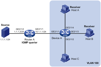
As shown in Figure 4, IGMPv2 runs on Router A and IGMPv2 snooping runs on Device A, with Router A acting as the IGMP querier.
Host A and Host B can receive only the multicast data for multicast group 224.1.1.1. Even if Host A and Host B temporarily fail to receive multicast data, the multicast data for group 224.1.1.1 can be forwarded through GigabitEthernet 2/1/3 and GigabitEthernet 2/1/4 of Device A. Device A can directly drops unknown multicast data to avoid broadcasting the data within its home VLAN.
Configuration procedure
Assign an IP address and subnet mask for each interface as per Figure 4. (Details not shown)
2. Configure Router A:
# Enable IP multicast routing, enable PIM-DM on each interface, and enable IGMP on GigabitEthernet 2/1/1.
<RouterA> system-view
[RouterA] multicast routing-enable
[RouterA] interface GigabitEthernet 2/1/1
[RouterA-GigabitEthernet2/1/1] igmp enable
[RouterA-GigabitEthernet2/1/1] pim dm
[RouterA-GigabitEthernet2/1/1] quit
[RouterA] interface GigabitEthernet 2/1/2
[RouterA-GigabitEthernet2/1/2] pim dm
[RouterA-GigabitEthernet2/1/2] quit
3. Configure Device A:
# Enable IGMP snooping globally.
<DeviceA> system-view
[DeviceA] igmp-snooping
[DeviceA-igmp-snooping] quit
# Switch the link mode of GigabitEthernet 2/1/1 through GigabitEthernet 2/1/4 to Layer 2 mode, create VLAN 100, assign GigabitEthernet 2/1/1 through GigabitEthernet 2/1/4 to this VLAN, enable IGMP snooping and the function of dropping unknown multicast packets in the VLAN.
[DeviceA] interface GigabitEthernet 2/1/1
[DeviceA-GigabitEthernet2/1/1] port link-mode bridge
[DeviceA-GigabitEthernet2/1/1] quit
[DeviceA] interface GigabitEthernet 2/1/2
[DeviceA-GigabitEthernet2/1/2] port link-mode bridge
[DeviceA-GigabitEthernet2/1/2] quit
[DeviceA] interface GigabitEthernet 2/1/3
[DeviceA-GigabitEthernet2/1/3] port link-mode bridge
[DeviceA-GigabitEthernet2/1/3] quit
[DeviceA] interface GigabitEthernet 2/1/4
[DeviceA-GigabitEthernet2/1/4] port link-mode bridge
[DeviceA-GigabitEthernet2/1/4] quit
[DeviceA] vlan 100
[DeviceA-vlan100] port GigabitEthernet 2/1/1 to GigabitEthernet 2/1/4
[DeviceA-vlan100] igmp-snooping enable
[DeviceA-vlan100] igmp-snooping drop-unknown
[DeviceA-vlan100] quit
# Configure a multicast group filter so that the receiver hosts in the VLAN can receive multicast data for multicast group 224.1.1.1 only.
[DeviceA] acl number 2001
[DeviceA-acl-basic-2001] rule permit source 224.1.1.1 0
[DeviceA-acl-basic-2001] quit
[DeviceA] igmp-snooping
[DeviceA-igmp-snooping] group-policy 2001 vlan 100
[DeviceA-igmp-snooping] quit
# Configure GigabitEthernet 2/1/3 and GigabitEthernet 2/1/4 to join multicast group 224.1.1.1 as simulated member hosts.
[DeviceA] interface GigabitEthernet 2/1/3
[DeviceA-GigabitEthernet2/1/3] igmp-snooping host-join 224.1.1.1 vlan 100
[DeviceA-GigabitEthernet2/1/3] quit
[DeviceA] interface GigabitEthernet 2/1/4
[DeviceA-GigabitEthernet2/1/4] igmp-snooping host-join 224.1.1.1 vlan 100
[DeviceA-GigabitEthernet2/1/4] quit
4. Verify the configuration:
# Display detailed IGMP snooping group information in VLAN 100 on Device A.
[DeviceA] display igmp-snooping group vlan 100 verbose
Total 1 IP Group(s).
Total 1 IP Source(s).
Total 1 MAC Group(s).
Port flags: D-Dynamic port, S-Static port, C-Copy port, P-PIM port
Subvlan flags: R-Real VLAN, C-Copy VLAN
Vlan(id):100.
Total 1 IP Group(s).
Total 1 IP Source(s).
Total 1 MAC Group(s).
Router port unit board: Mask(0x000004)
Router port(s):total 1 port(s).
GE2/1/1 (D)
IP group(s):the following ip group(s) match to one mac group.
IP group address:224.1.1.1
(0.0.0.0, 224.1.1.1):
Attribute: Host Port
Host port unit board: Mask(0x000004)
Host port(s):total 2 port(s)..
GE2/1/3 (D)
GE2/1/4 (D)
MAC group(s):
MAC group address:0100-5e01-0101
Host port(s):total 2 port(s).
GE2/1/3
GE2/1/4
The output shows that GigabitEthernet 2/1/3 and GigabitEthernet 2/1/4 of Device A has joined multicast group 224.1.1.1.
Static port configuration
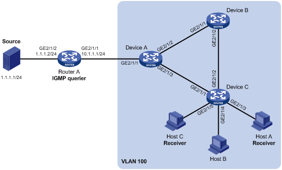
Network requirements
As shown in Figure 5, IGMPv2 runs on Router A, and IGMPv2 snooping runs on Device A, Device B and Device C, with Router A acting as the IGMP querier.
Host A and host C are permanent receivers of multicast group 224.1.1.1. GigabitEthernet 2/1/3 and GigabitEthernet 2/1/5 on Device C are required to be configured as static member ports for multicast group 224.1.1.1 to enhance the reliability of multicast traffic transmission.
Suppose STP runs on the network. To avoid data loops, the forwarding path from Device A to Device C is blocked under normal conditions, and multicast traffic flows to the receivers attached to Device C only along the path of Device A—Device B—Device C. Configure GigabitEthernet 2/1/3 that connects Device A to Device C as a static router port, so that multicast traffic can flows to the receivers nearly uninterruptedly along the path of Device A—Device C in the case that the path of Device A—Device B—Device C gets blocked.
|
|
NOTE: · If no static router port is configured, when the path of Device A—Device B—Device C gets blocked, at least one IGMP query-response cycle must be completed before the multicast data can flow to the receivers along the new path of Device A—Device C, namely multicast delivery will be interrupted during this process. · For more information about the Spanning Tree Protocol (STP), see Layer 2—LAN Switching Configuration Guide. |
Configuration procedure
1. Assign IP addresses:
Assign an IP address and subnet mask for each interface as per Figure 5. (Details not shown)
2. Configure Router A:
# Enable IP multicast routing, enable PIM-DM on each interface, and enable IGMP on GigabitEthernet 2/1/1.
<RouterA> system-view
[RouterA] multicast routing-enable
[RouterA] interface GigabitEthernet 2/1/1
[RouterA-GigabitEthernet2/1/1] igmp enable
[RouterA-GigabitEthernet2/1/1] pim dm
[RouterA-GigabitEthernet2/1/1] quit
[RouterA] interface GigabitEthernet 2/1/2
[RouterA-GigabitEthernet2/1/2] pim dm
[RouterA-GigabitEthernet2/1/2] quit
3. Configure Device A:
# Enable IGMP snooping globally.
<DeviceA> system-view
[DeviceA] igmp-snooping
[DeviceA-igmp-snooping] quit
# Switch the link mode of GigabitEthernet 2/1/1 through GigabitEthernet 2/1/3 to Layer 2 mode, create VLAN 100, assign GigabitEthernet 2/1/1 through GigabitEthernet 2/1/3 to this VLAN, and enable IGMP snooping in the VLAN.
[DeviceA] interface GigabitEthernet 2/1/1
[DeviceA-GigabitEthernet2/1/1] port link-mode bridge
[DeviceA-GigabitEthernet2/1/1] quit
[DeviceA] interface GigabitEthernet 2/1/2
[DeviceA-GigabitEthernet2/1/2] port link-mode bridge
[DeviceA-GigabitEthernet2/1/2] quit
[DeviceA] interface GigabitEthernet 2/1/3
[DeviceA-GigabitEthernet2/1/3] port link-mode bridge
[DeviceA-GigabitEthernet2/1/3] quit
[DeviceA] vlan 100
[DeviceA-vlan100] port GigabitEthernet 2/1/1 to GigabitEthernet 2/1/3
[DeviceA-vlan100] igmp-snooping enable
[DeviceA-vlan100] quit
# Configure GigabitEthernet 2/1/3 to be a static router port.
[DeviceA] interface GigabitEthernet 2/1/3
[DeviceA-GigabitEthernet2/1/3] igmp-snooping static-router-port vlan 100
[DeviceA-GigabitEthernet2/1/3] quit
4. Configure Device B:
# Enable IGMP snooping globally.
<DeviceB> system-view
[DeviceB] igmp-snooping
[DeviceB-igmp-snooping] quit
# Switch the link mode of GigabitEthernet 2/1/1 through GigabitEthernet 2/1/2 to Layer 2 mode, create VLAN 100, assign GigabitEthernet 2/1/1 and GigabitEthernet 2/1/2 to this VLAN, and enable IGMP snooping in the VLAN.
[DeviceB] interface GigabitEthernet 2/1/1
[DeviceB-GigabitEthernet2/1/1] port link-mode bridge
[DeviceB-GigabitEthernet2/1/1] quit
[DeviceB] interface GigabitEthernet 2/1/2
[DeviceB-GigabitEthernet2/1/2] port link-mode bridge
[DeviceB-GigabitEthernet2/1/2] quit
[DeviceB] vlan 100
[DeviceB-vlan100] port GigabitEthernet 2/1/1 GigabitEthernet 2/1/2
[DeviceB-vlan100] igmp-snooping enable
[DeviceB-vlan100] quit
5. Configure Device C:
# Enable IGMP snooping globally.
<DeviceC> system-view
[DeviceC] igmp-snooping
[DeviceC-igmp-snooping] quit
# Switch the link mode of GigabitEthernet 2/1/1 through GigabitEthernet 2/1/5 to Layer 2 mode, create VLAN 100, assign GigabitEthernet 2/1/1 through GigabitEthernet 2/1/5 to this VLAN, and enable IGMP snooping in the VLAN.
[DeviceC] interface GigabitEthernet 2/1/1
[DeviceC-GigabitEthernet2/1/1] port link-mode bridge
[DeviceC-GigabitEthernet2/1/1] quit
[DeviceC] interface GigabitEthernet 2/1/2
[DeviceC-GigabitEthernet2/1/2] port link-mode bridge
[DeviceC-GigabitEthernet2/1/2] quit
[DeviceC] interface GigabitEthernet 2/1/3
[DeviceC-GigabitEthernet2/1/3] port link-mode bridge
[DeviceC-GigabitEthernet2/1/3] quit
[DeviceC] interface GigabitEthernet 2/1/4
[DeviceC-GigabitEthernet2/1/4] port link-mode bridge
[DeviceC-GigabitEthernet2/1/4] quit
[DeviceC] interface GigabitEthernet 2/1/5
[DeviceC-GigabitEthernet2/1/5] port link-mode bridge
[DeviceC-GigabitEthernet2/1/5] quit
[DeviceC] vlan 100
[DeviceC-vlan100] port GigabitEthernet 2/1/1 to GigabitEthernet 2/1/5
[DeviceC-vlan100] igmp-snooping enable
[DeviceC-vlan100] quit
# Configure GigabitEthernet 2/1/3 and GigabitEthernet 2/1/5 as static member ports for multicast group 224.1.1.1.
[DeviceC] interface GigabitEthernet 2/1/3
[DeviceC-GigabitEthernet2/1/3] igmp-snooping static-group 224.1.1.1 vlan 100
[DeviceC-GigabitEthernet2/1/3] quit
[DeviceC] interface GigabitEthernet 2/1/5
[DeviceC-GigabitEthernet2/1/5] igmp-snooping static-group 224.1.1.1 vlan 100
[DeviceC-GigabitEthernet2/1/5] quit
6. Verify the configuration:
# Display detailed IGMP snooping group information in VLAN 100 on Device A.
[DeviceA] display igmp-snooping group vlan 100 verbose
Total 1 IP Group(s).
Total 1 IP Source(s).
Total 1 MAC Group(s).
Port flags: D-Dynamic port, S-Static port, C-Copy port, P-PIM port
Subvlan flags: R-Real VLAN, C-Copy VLAN
Vlan(id):100.
Total 1 IP Group(s).
Total 1 IP Source(s).
Total 1 MAC Group(s).
Router port unit board: Mask(0x000004)
Router port(s):total 2 port(s).
GE2/1/1 (D)
GE2/1/3 (S)
IP group(s):the following ip group(s) match to one mac group.
IP group address:224.1.1.1
(0.0.0.0, 224.1.1.1):
Attribute: Host Port
Host port unit board: Mask(0x000004)
Host port(s):total 1 port(s).
GE2/1/2 (D)
MAC group(s):
MAC group address:0100-5e01-0101
Host port(s):total 1 port(s).
GE2/1/2
The output shows that GigabitEthernet 2/1/3 of Device A has become a static router port.
# Display detailed IGMP snooping group information in VLAN 100 on Device C.
[DeviceC] display igmp-snooping group vlan 100 verbose
Total 1 IP Group(s).
Total 1 IP Source(s).
Total 1 MAC Group(s).
Port flags: D-Dynamic port, S-Static port, C-Copy port, P-PIM port
Subvlan flags: R-Real VLAN, C-Copy VLAN
Vlan(id):100.
Total 1 IP Group(s).
Total 1 IP Source(s).
Total 1 MAC Group(s).
Router port unit board: Mask(0x000004)
Router port(s):total 1 port(s).
GE2/1/2 (D)
IP group(s):the following ip group(s) match to one mac group.
IP group address:224.1.1.1
(0.0.0.0, 224.1.1.1):
Attribute: Host Port
Host port unit board: Mask(0x000004)
Host port(s):total 2 port(s).
GE2/1/3 (S)
GE2/1/5 (S)
MAC group(s):
MAC group address:0100-5e01-0101
Host port(s):total 2 port(s).
GE2/1/3
GE2/1/5
The output shows that GigabitEthernet 2/1/3 and GigabitEthernet 2/1/5 on Device C have become static member ports for multicast group 224.1.1.1.
IGMP snooping querier configuration
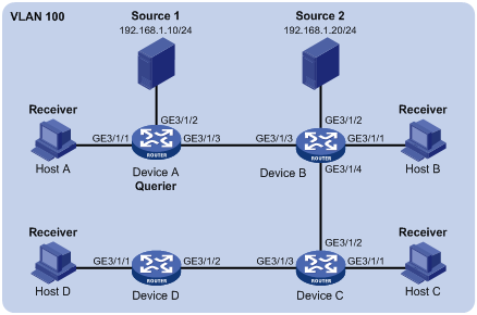
Network requirements
As shown in Figure 6, in a Layer 2–only network environment, two multicast sources Source 1 and Source 2 send multicast data to multicast groups 224.1.1.1 and 225.1.1.1 respectively, Host A and Host C are receivers of multicast group 224.1.1.1, while Host B and Host D are receivers of multicast group 225.1.1.1. IGMPv2 runs on all the receiver hosts. IGMPv2 snooping runs on Device A, Device B, and Device C. Device A serves as the IGMP-snooping querier.
To prevent flooding of unknown multicast traffic within the VLAN, configure all the devices to drop unknown multicast data packets. Configure a non-all-zero IP address as the source IP address of IGMP queries to ensure normal creation of multicast forwarding entries.
Configuration procedure
1. Configure Device A:
# Enable IGMP snooping globally.
<DeviceA> system-view
[DeviceA] igmp-snooping
[DeviceA-igmp-snooping] quit
# Switch the link mode of GigabitEthernet 3/1/1 through GigabitEthernet 3/1/3 to Layer 2 mode, create VLAN 100 and assign GigabitEthernet 3/1/1 and GigabitEthernet 3/1/3 to VLAN 100.
[DeviceA] interface GigabitEthernet 3/1/1
[DeviceA-GigabitEthernet3/1/1] port link-mode bridge
[DeviceA-GigabitEthernet3/1/1] quit
[DeviceA] interface GigabitEthernet 3/1/2
[DeviceA-GigabitEthernet3/1/2] port link-mode bridge
[DeviceA-GigabitEthernet3/1/2] quit
[DeviceA] interface GigabitEthernet 3/1/3
[DeviceA-GigabitEthernet3/1/3] port link-mode bridge
[DeviceA-GigabitEthernet3/1/3] quit
[DeviceA] vlan 100
[DeviceA-vlan100] port GigabitEthernet 3/1/1 GigabitEthernet 3/1/3
# Enable IGMP snooping and the function of dropping unknown multicast packets in VLAN 100.
[DeviceA-vlan100] igmp-snooping enable
[DeviceA-vlan100] igmp-snooping drop-unknown
# Configure the IGMP snooping querier feature in VLAN 100.
[DeviceA-vlan100] igmp-snooping querier
# Set the source IP address of IGMP general queries and group-specific queries to 192.168.1.1 in VLAN 100.
[DeviceA-vlan100] igmp-snooping general-query source-ip 192.168.1.1
[DeviceA-vlan100] igmp-snooping special-query source-ip 192.168.1.1
[DeviceA-vlan100] quit
2. Configure Device B:
# Enable IGMP snooping globally.
<DeviceB> system-view
[DeviceB] igmp-snooping
[DeviceB-igmp-snooping] quit
# Switch the link mode of GigabitEthernet 3/1/1 through GigabitEthernet 3/1/4 to Layer 2 mode, create VLAN 100, add GigabitEthernet 3/1/1 through GigabitEthernet 3/1/4 to VLAN 100.
[DeviceB] interface GigabitEthernet 3/1/1
[DeviceB-GigabitEthernet3/1/1] port link-mode bridge
[DeviceB-GigabitEthernet3/1/1] quit
[DeviceB] interface GigabitEthernet 3/1/2
[DeviceB-GigabitEthernet3/1/2] port link-mode bridge
[DeviceB-GigabitEthernet3/1/2] quit
[DeviceB] interface GigabitEthernet 3/1/3
[DeviceB-GigabitEthernet3/1/3] port link-mode bridge
[DeviceB-GigabitEthernet3/1/3] quit
[DeviceB] interface GigabitEthernet 3/1/4
[DeviceB-GigabitEthernet3/1/4] port link-mode bridge
[DeviceB-GigabitEthernet3/1/4] quit
[DeviceB] vlan 100
[DeviceB-vlan100] port GigabitEthernet 3/1/1 to GigabitEthernet 3/1/4
[DeviceB-vlan100] igmp-snooping enable
# Enable IGMP snooping and the function of dropping unknown multicast packets in VLAN 100.
[DeviceB-vlan100] igmp-snooping enable
[DeviceB -vlan100] igmp-snooping drop-unknown
[DeviceB -vlan100] quit
The configuration on Device C and Device B is similar to that on Device B.
3. Verify the configuration:
After the IGMP snooping querier starts to work, all the devices but the querier can receive IGMP general queries. You can use the display igmp-snooping statistics command to display statistics for the received IGMP messages.
# Display statistics for IGMP messages on Device B.
[DeviceB] display igmp-snooping statistics
Received IGMP general queries:3.
Received IGMPv1 reports:0.
Received IGMPv2 reports:12.
Received IGMP leaves:0.
Received IGMPv2 specific queries:0.
Sent IGMPv2 specific queries:0.
Received IGMPv3 reports:0.
Received IGMPv3 reports with right and wrong records:0.
Received IGMPv3 specific queries:0.
Received IGMPv3 specific sg queries:0.
Sent IGMPv3 specific queries:0.
Sent IGMPv3 specific sg queries:0.
Received error IGMP messages:0.
The output shows that Device B has received IGMP general queries. This means that Device A is working as the IGMP snooping querier on the network.
IGMP snooping proxying configuration example
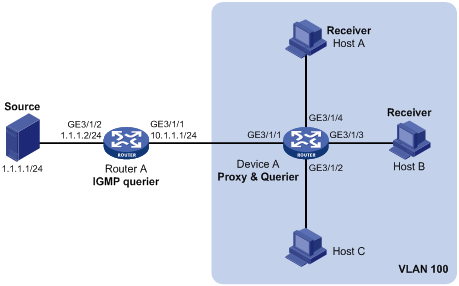
Network requirements
As shown in Figure 7, Router A runs IGMPv2 and Device A runs IGMPv2 snooping. Router A serves as an IGMP querier.
Configure IGMP snooping proxying on Device A, enabling the device to forward IGMP reports and leave messages on behalf of attached hosts and to respond to IGMP queries from Router A and forward the queries to the hosts on behalf of Router A.
Configuration procedure
1. Assign IP addresses for interfaces:
Assign an IP address and subnet mask for each interface as per Figure 7. (Details not shown)
2. Configure Router A:
# Enable IP multicast routing, enable PIM-DM on each interface, and enable IGMP on GigabitEthernet 3/1/1.
<RouterA> system-view
[RouterA] multicast routing-enable
[RouterA] interface GigabitEthernet 3/1/1
[RouterA-GigabitEthernet3/1/1] igmp enable
[RouterA-GigabitEthernet3/1/1] pim dm
[RouterA-GigabitEthernet3/1/1] quit
[RouterA] interface GigabitEthernet 3/1/2
[RouterA-GigabitEthernet3/1/2] pim dm
[RouterA-GigabitEthernet3/1/2] quit
3. Configure Device A:
# Enable IGMP snooping globally.
<DeviceA> system-view
[DeviceA] igmp-snooping
[DeviceA-igmp-snooping] quit
# Switch the link mode of GigabitEthernet 3/1/1 through GigabitEthernet 3/1/4 to Layer 2 mode, create VLAN 100, assign ports GigabitEthernet 3/1/1 through GigabitEthernet 3/1/4 to this VLAN, and enable IGMP snooping and IGMP snooping proxying in the VLAN.
[DeviceA] interface GigabitEthernet 3/1/1
[DeviceA-GigabitEthernet3/1/1] port link-mode bridge
[DeviceA-GigabitEthernet3/1/1] quit
[DeviceA] interface GigabitEthernet 3/1/2
[DeviceA-GigabitEthernet3/1/2] port link-mode bridge
[DeviceA-GigabitEthernet3/1/2] quit
[DeviceA] interface GigabitEthernet 3/1/3
[DeviceA-GigabitEthernet3/1/3] port link-mode bridge
[DeviceA-GigabitEthernet3/1/3] quit
[DeviceA] interface GigabitEthernet 3/1/4
[DeviceA-GigabitEthernet3/1/4] port link-mode bridge
[DeviceA-GigabitEthernet3/1/4] quit
[DeviceA] vlan 100
[DeviceA-vlan100] port GigabitEthernet 3/1/1 to GigabitEthernet 3/1/4
[DeviceA-vlan100] igmp-snooping enable
[DeviceA-vlan100] igmp-snooping proxying enable
[DeviceA-vlan100] quit
4. Verify the configuration:
After the configuration is completed, Host A and Host B send IGMP join messages for group 224.1.1.1. Receiving the messages, Device A sends a join message for the group out port GigabitEthernet 3/1/1 (a router port) to Router A.
Use the display igmp-snooping group command and the display igmp group command to display information about IGMP snooping groups and IGMP groups. For example:
# Display information about IGMP snooping groups on Device A.
[DeviceA] display igmp-snooping group
Total 1 IP Group(s).
Total 1 IP Source(s).
Total 1 MAC Group(s).
Port flags: D-Dynamic port, S-Static port, C-Copy port, P-PIM port
Subvlan flags: R-Real VLAN, C-Copy VLAN
Vlan(id):100.
Total 1 IP Group(s).
Total 1 IP Source(s).
Total 1 MAC Group(s).
Router port(s):total 1 port(s).
GE3/1/1 (D)
IP group(s):the following ip group(s) match to one mac group.
IP group address:224.1.1.1
(0.0.0.0, 224.1.1.1):
Host port(s):total 2 port(s).
GE3/1/3 (D)
GE3/1/4 (D)
MAC group(s):
MAC group address:0100-5e01-0101
Host port(s):total 2 port(s).
GE3/1/3
GE3/1/4
# Display information about IGMP groups on Router A.
[RouterA] display igmp group
Total 1 IGMP Group(s).
Interface group report information of VPN-Instance: public net
GigabitEthernet3/1/1(10.1.1.1):
Total 1 IGMP Group reported
Group Address Last Reporter Uptime Expires
224.1.1.1 0.0.0.0 00:00:06 00:02:04
When Host A leaves the multicast group, it sends an IGMP leave message to Device A. Receiving the message, Device A removes port GigabitEthernet 3/1/4 from the member port list of the forwarding entry for the group; however, it does not remove the group or forward the leave message to Router A because Host B is still in the group. Use the display igmp-snooping group command to display information about IGMP snooping groups. For example:
# Display information about IGMP snooping groups on Device A.
[DeviceA] display igmp-snooping group
Total 1 IP Group(s).
Total 1 IP Source(s).
Total 1 MAC Group(s).
Port flags: D-Dynamic port, S-Static port, C-Copy port, P-PIM port
Subvlan flags: R-Real VLAN, C-Copy VLAN
Vlan(id):100.
Total 1 IP Group(s).
Total 1 IP Source(s).
Total 1 MAC Group(s).
Router port(s):total 1 port(s).
GE3/1/1 (D)
IP group(s):the following ip group(s) match to one mac group.
IP group address:224.1.1.1
(0.0.0.0, 224.1.1.1):
Host port(s):total 1 port(s).
GE3/1/3 (D)
MAC group(s):
MAC group address:0100-5e01-0101
Host port(s):total 1 port(s).
GE3/1/3
Troubleshooting IGMP snooping
Layer 2 multicast forwarding cannot function
Symptom
Layer 2 multicast forwarding cannot function.
Analysis
IGMP snooping is not enabled.
Solution
1. Use the display current-configuration command to view the running status of IGMP snooping.
2. If IGMP snooping is not enabled, use the igmp-snooping command in system view to enable IGMP snooping globally, and then use the igmp-snooping enable command in VLAN view to enable IGMP snooping for the VLAN.
3. If IGMP snooping is enabled globally but not enabled for the VLAN, use the igmp-snooping enable command in VLAN view to enable IGMP snooping for the VLAN.
Configured multicast group policy fails to take effect
Symptom
Although a multicast group policy has been configured to allow hosts to join specific multicast groups, the hosts can still receive multicast data addressed to other multicast groups.
Analysis
· The ACL rule is incorrectly configured.
· The multicast group policy is not correctly applied.
· The function of dropping unknown multicast data is not enabled, so unknown multicast data is flooded.
Solution
1. Use the display acl command to check the configured ACL rule. Make sure that the ACL rule conforms to the multicast group policy to be implemented.
2. Use the display this command in IGMP-snooping view or in the corresponding interface view to verify that the correct multicast group policy has been applied. If not, use the group-policy or igmp-snooping group-policy command to apply the correct multicast group policy.
3. Use the display current-configuration command to verify that the function of dropping unknown multicast data is enabled. If not, use the drop-unknown or igmp-snooping drop-unknown command to enable the function of dropping unknown multicast data.
Appendix
Processing of multicast protocol messages
With Layer 3 multicast routing enabled, an IGMP snooping–enabled switch processes multicast protocol messages differently under different conditions, as follows:
· If only IGMP is enabled on the switch, or if both IGMP and PIM are enabled on the switch, the switch does the following:
¡ Maintains dynamic member ports or dynamic router ports according to IGMP packets
¡ Maintains dynamic router ports according to PIM hello packets
· If only PIM is enabled on the switch, the following occur:
¡ The switch broadcasts IGMP messages as unknown messages in the VLAN.
¡ After receiving a PIM hello message, the switch maintains the corresponding dynamic router port.
· If IGMP is disabled on the switch, one of the following occurs:
¡ If PIM is disabled, the switch deletes all its dynamic member ports and dynamic router ports.
¡ If PIM is enabled, the switch deletes only its dynamic member ports but not its dynamic router ports.
|
|
NOTE: On a switch with Layer-3 multicast routing enabled, use the display igmp group port-info command to view Layer-2 port information. For more information about this command, see IP Multicast Command Reference. |
· If PIM is disabled on the switch, one of the following occurs:
¡ If IGMP is disabled, the switch deletes all its dynamic router ports.
¡ If IGMP is enabled, the switch maintains all its dynamic member ports and dynamic router ports.