- Table of Contents
-
- 05-Layer 3 - IP Services Configuration Guide
- 00-Preface
- 01-ARP Configuration
- 02-IP Addressing Configuration
- 03-DHCP Configuration
- 04-DNS Configuration
- 05-NAT Configuration
- 06-IP Performance Optimization Configuration
- 07-Adjacency Table Configuration
- 08-UDP Helper Configuration
- 09-IPv6 Basics Configuration
- 10-DHCPv6 Configuration
- 11-IPv6 DNS Configuration
- 12-NAT-PT Configuration
- 13-Tunneling Configuration
- 14-GRE Configuration
- Related Documents
-
| Title | Size | Download |
|---|---|---|
| 13-Tunneling Configuration | 376.07 KB |
Contents
Tunneling configuration task list
Configuring a tunnel interface
Configuring an IPv6 manual tunnel
Configuring an automatic IPv4-compatible IPv6 tunnel
6to4 tunnel configuration example
6to4 relay configuration example
Configuring an IPv4 over IPv4 tunnel
Displaying and maintaining tunneling configuration
Troubleshooting tunneling configuration
Tunneling overview
Tunneling is an encapsulation technology, which uses one network protocol to encapsulate packets of another network protocol and transfer them over a virtual point-to-point connection. The virtual connection is called a tunnel. Packets are encapsulated and de-encapsulated at both ends of a tunnel. Tunneling refers to the whole process from data encapsulation to data transfer to data de-encapsulation.
Tunneling provides the following features:
· Transition techniques, such as IPv6 over IPv4 tunneling, to interconnect IPv4 and IPv6 networks.
· Virtual Private Networks (VPNs) for guaranteeing communication security, such as IPv4 over IPv4 tunneling and Generic Routing Encapsulation (GRE).
· Traffic engineering, such as Multiprotocol Label Switching traffic engineering (MPLS TE) to prevent network congestion.
Unless otherwise specified, the term tunnel in this document refers to an IPv4/IPv6 transition tunnel or IPv4 over IPv6 tunnel.
|
|
NOTE: · For more information about GRE, see the chapter “GRE configuration.” · For more information about MPLS TE, see MPLS TE Configuration Guide. |
IPv6 over IPv4 tunnels
Implementation
The IPv6 over IPv4 tunneling adds an IPv4 header to IPv6 data packets so that IPv6 packets can pass an IPv4 network through a tunnel to realize internetworking between isolated IPv6 networks, as shown in Figure 1. The IPv6 over IPv4 tunnel can be established between two hosts, a host and a device, or two devices. The tunnel destination node can forward IPv6 packets if it is not the destination of the IPv6 packets.
|
|
CAUTION: The routers at both ends of an IPv6 over IPv4 tunnel must support IPv4/IPv6 dual stack. |
Figure 1 Principle of IPv6 over IPv4 tunnel
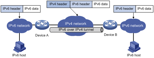
The IPv6 over IPv4 tunnel processes packets in the following ways:
1. A host in the IPv6 network sends an IPv6 packet to Device A at the tunnel source.
2. After determining according to the routing table that the packet needs to be forwarded through the tunnel, Device A encapsulates the IPv6 packet with an IPv4 header and forwards it through the physical interface of the tunnel.
3. Upon receiving the packet, Device B de-encapsulates the packet.
4. Device B forwards the packet according to the destination address in the de-encapsulated IPv6 packet. If the destination address is the device itself, Device B forwards the IPv6 packet to the upper-layer protocol for processing.
Tunnel types
IPv6 over IPv4 tunnels are divided into manually configured tunnels and automatic tunnels, depending on how the IPv4 address of the tunnel destination is acquired.
· Manually configured tunnel—The destination address of the tunnel cannot be automatically acquired through the destination IPv6 address of an IPv6 packet at the tunnel source, and must be manually configured.
· Automatic tunnel—The destination address of the tunnel is an IPv6 address with an IPv4 address embedded, and the IPv4 address can be automatically acquired through the destination IPv6 address of an IPv6 packet at the tunnel source.
According to the way an IPv6 packet is encapsulated, IPv6 over IPv4 tunnels are divided into the following modes.
Table 1 IPv6 over IPv4 tunnel modes and key parameters
|
Tunnel type |
Tunnel mode |
Tunnel source/destination address |
Tunnel interface address type |
|
Manually configured tunnel |
IPv6 manual tunneling |
The source/destination IP address is a manually configured IPv4 address. |
IPv6 address |
|
IPv6-over-IPv4 GRE tunneling |
The source/destination IP address is a manually configured IPv4 address. |
IPv6 address |
|
|
Automatic tunnel |
Automatic IPv4-compatible IPv6 tunneling |
The source IP address is a manually configured IPv4 address. The destination IP address need not be configured. |
IPv4-compatible IPv6 address, in the format of ::IPv4-source-address/96 |
|
6to4 tunneling |
The source IP address is a manually configured IPv4 address. The destination IP address need not be configured. |
6to4 address, in the format of 2002:IPv4-source-address::/48 |
|
|
Intra-site automatic tunnel addressing protocol (ISATAP) tunneling |
The source IP address is a manually configured IPv4 address. The destination IP address need not be configured. |
ISATAP address, in the format of Prefix:0:5EFE:IPv4-source-address/64 |
IPv6 manual tunneling
A manually configured tunnel is a point-to-point link. One link is a separate tunnel. The IPv6 manually configured tunnels provide stable connections requiring regular secure communication between two border routers or between a border router and a host for access to remote IPv6 networks.
1. IPv6-over-IPv4 GRE tunneling
IPv6 packets can be carried over IPv6-over-IPv4 GRE tunnels to pass through an IPv4 network. Like an IPv6 manually configured tunnel, an IPv6-over-IPv4 GRE tunnel is a point-to-point link. IPv6-over-IPv4 GRE tunnels are mainly used to provide stable connections for secure communication between border routers or between host and border router. For more information, see the chapter “GRE configuration.”
2. Automatic IPv4-compatible IPv6 tunnel
An automatic IPv4-compatible IPv6 tunnel is a point-to-multipoint link. IPv4-compatible IPv6 addresses are adopted at both ends of such a tunnel. The address format is 0:0:0:0:0:0:a.b.c.d/96, where a.b.c.d represents an embedded IPv4 address. The tunnel destination is automatically determined by the embedded IPv4 address, which makes it easy to create a tunnel for IPv6 over IPv4. However, an automatic IPv4-compatible IPv6 tunnel must use IPv4-compatible IPv6 addresses and it is still dependent on IPv4 addresses. Therefore, automatic IPv4-compatible IPv6 tunnels have limitations.
3. 6to4 tunnel
Ordinary 6to4 tunnel
An automatic 6to4 tunnel is a point-to-multipoint tunnel and is used to connect multiple isolated IPv6 networks over an IPv4 network to remote IPv6 networks. The embedded IPv4 address in an IPv6 address is used to automatically acquire the destination IPv4 address of the tunnel.
The automatic 6to4 tunnel adopts 6to4 addresses. The address format is 2002:abcd:efgh:subnet number::interface ID/64, where abcd:efgh represents the 32-bit globally unique source IPv4 address of the 6to4 tunnel, in hexadecimal notation. For example, 1.1.1.1 can be represented by 0101:0101. The part that follows 2002:abcd:efgh uniquely identifies a host in a 6to4 network. The tunnel destination is automatically determined by the embedded IPv4 address, which makes it easy to create a 6to4 tunnel.
Since the 16-bit subnet number of the 64-bit address prefix in 6to4 addresses can be customized and the first 48 bits in the address prefix are fixed by a permanent value and the IPv4 address of the tunnel source or destination, it is possible that IPv6 packets can be forwarded by the tunnel. A 6to4 tunnel interconnects IPv6 networks over an IPv4 network, and overcomes the limitations of an automatic IPv4-compatible IPv6 tunnel.
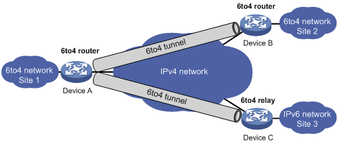
A 6to4 tunnel is only used to connect 6to4 networks, whose IP prefix must be 2002::/16. However, IPv6 network addresses with the prefix such as 2001::/16 may also be used in IPv6 networks. To connect a 6to4 network to an IPv6 network, a 6to4 router must be used as a gateway to forward packets to the IPv6 network. Such a router is called 6to4 relay router.
As shown in Figure 2, a static route must be configured on the border router (Device A) in the 6to4 network and the next-hop address must be the 6to4 address of the 6to4 relay router (Device C). In this way, all packets destined for the IPv6 network will be forwarded to the 6to4 relay router, and then to the IPv6 network. Thus, internetworking between the 6to4 network (with the address prefix starting with 2002) and the IPv6 network is realized.
4. ISATAP tunnel
With the application of the IPv6 technology, there will be more and more IPv6 hosts in the existing IPv4 network. The ISATAP tunneling technology provides a satisfactory solution for IPv6 application. An ISATAP tunnel is a point-to-multipoint automatic tunnel. The destination of a tunnel can automatically be acquired from the embedded IPv4 address in the destination address of an IPv6 packet.
When an ISATAP tunnel is used, the destination address of an IPv6 packet and the IPv6 address of a tunnel interface both adopt special ISATAP addresses. The ISATAP address format is prefix(64bit):0:5EFE:abcd:efgh. The 64-bit prefix is the prefix of a valid IPv6 unicast address, but abcd:efgh is a 32-bit source IPv4 address in hexadecimal, which might not be globally unique. Through the embedded IPv4 address, an ISATAP tunnel can be automatically created to transfer IPv6 packets.
The ISATAP tunnel is mainly used for communication between IPv6 routers or between a host and an IPv6 router over an IPv4 network.
Figure 3 Principle of ISATAP tunnel

IPv4 over IPv4 tunnel
Introduction
The IPv4 over IPv4 tunneling (specified in RFC 1853) is developed for IP data packet encapsulation so that data can be transferred from one IPv4 network to another IPv4 network.
Encapsulation and de-encapsulation
Figure 4 Principle of IPv4 over IPv4 tunneling
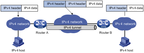
Packets traveling through a tunnel undergo encapsulation and de-encapsulation processes, as shown in Figure 4.
· Encapsulation
The encapsulation process is as follows:
a. Router A receives an IP packet from an IPv4 host and submits it to the IP protocol stack.
b. The IP protocol stack determines how to forward the packet according to the destination address in the IP header. If the packet is destined for the IPv4 host connected to Router B, Router A delivers the packet to the tunnel interface.
c. The tunnel interface encapsulates the packet into an IPv4 packet and submitted to the IP protocol stack. The IP protocol stack determines the outgoing interface of the tunnel according to the IP header, and sends the packet out.
· De-encapsulation
a. After receiving the packet, Router B delivers it to the IP protocol stack, which then checks the protocol number in the IP header.
b. If the protocol number is IPv4 (indicating an IPv4 packet is encapsulated within the packet), the IP packet is sent to the tunnel module for de-encapsulation.
c. The de-encapsulated IP packet is sent back to the IP protocol stack for processing.
Protocols and standards
· RFC 1853, IP in IP Tunneling
· RFC 2473, Generic Packet Tunneling in IPv6 Specification
· RFC 2893, Transition Mechanisms for IPv6 Hosts and Routers
· RFC 3056, Connection of IPv6 Domains via IPv4 Clouds
· RFC 4214, Intra-Site Automatic Tunnel Addressing Protocol (ISATAP)
Tunneling configuration task list
Complete the following tasks to configure the tunneling feature:
|
Task |
Remarks |
|
|
Required |
||
|
Configuring IPv6 over IPv4 tunnel |
Optional Use one as needed. |
|
|
Optional |
||
|
|
NOTE: For how to configure the IPv6 MTU of a tunnel interface, see the ipv6 mtu command in Layer 3—IP Services Command Reference. |
Configuring a tunnel interface
Configure a Layer 3 virtual tunnel interface on each device on a tunnel so that devices at both ends can send, identify, and process packets from the tunnel.
To configure a tunnel interface:
|
Step |
Command |
Remarks |
|
1. Enter system view. |
system-view |
N/A |
|
2. Create a tunnel interface and enter its view. |
interface tunnel number |
By default, no tunnel interface is created. |
|
3. Configure the description for the interface. |
description text |
Optional. By default, the description of a tunnel interface is the interface name followed by the "Interface" string. |
|
4. Specify the service card for forwarding the traffic on the interface (distributed devices). |
service slot slot-number |
Optional. Not specified by default. |
|
5. Set the MTU for IPv4 or IPv6 packets sent over the interface. |
·
Set the MTU for IPv4 packets sent over the interface: ·
Set the MTU of IPv6 packets sent over the interface: |
Optional. Use either command as needed. 1500 by default. |
|
6. Set the bandwidth for the tunnel interface. |
tunnel bandwidth bandwidth-value |
Optional. By default, the bandwidth of the tunnel interface is 64 kbps. |
|
7. Restore the default settings. |
default |
Optional. |
|
8. Shut down the tunnel interface. |
shutdown |
Optional. By default, the interface is up. |
|
|
NOTE: · When active/standby switchover occurs or the standby card is removed from a distributed device, tunnels configured on the active or standby card still exist. To delete tunnels, use the undo interface tunnel command. · For more information about the ipv6 mtu command, see Layer 3—IP Services Command Reference. · The tunnel bandwidth command does not change the actual bandwidth of the tunnel interface, but sets a bandwidth value for dynamical routing protocols to calculate the cost of a tunnel path. You can determine the value according to the bandwidth of the output interface. |
Configuring an IPv6 manual tunnel
Configuration prerequisites
Configure IP addresses for interfaces (such as the VLAN interface, Ethernet interface, and loopback interface) on the router to ensure normal communication. One of the interfaces will be used as the source interface of the tunnel.
Configuration guidelines
When you configure an IPv6 manual tunnel, follow these guidelines:
· After a tunnel interface is deleted, all the above features configured on the tunnel interface will be deleted.
· To encapsulate and forward IPv6 packets whose destination address does not belong to the network segment where the receiving tunnel interface resides, you need to configure a static route or dynamic routing for forwarding those packets through this tunnel interface. If you configure a static route to that destination IPv6 address, specify this tunnel interface as the outbound interface, or the peer tunnel interface address as the next hop. A similar configuration needs to be performed at the other tunnel end. If you configure dynamic routing at both ends, enable the dynamic routing protocol on both tunnel interfaces. For the detailed configuration, see Layer 3—IP Routing Configuration Guide.
Configuration procedure
To configure an IPv6 manual tunnel:
|
Step |
Command |
Remarks |
|
1. Enter system view. |
system-view |
N/A |
|
2. Enable IPv6. |
ipv6 |
By default, the IPv6 packet forwarding function is disabled. |
|
3. Enter tunnel interface view. |
interface tunnel number |
N/A |
|
4. Configure an IPv6 address for the tunnel interface. |
· Configure a global unicast IPv6 address or a site-local address: ¡ ipv6 address { ipv6-address prefix-length | ipv6-address | prefix-length } ¡ ipv6 address ipv6-address | prefix-length eui-64 · Configure a link-local IPv6 address: a. ipv6 address auto link-local b. ipv6 address ipv6-address link-local |
Use either the ipv6 address { ipv6-address prefix-length | ipv6-address | prefix-length } or the ipv6 address ipv6-address | prefix-length eui-64 command to configure a global unicast IPv6 address or a site-local address. By default, · No IPv6 global unicast address or site-local address is configured for the tunnel interface. · A link-local address will automatically be created when an IPv6 global unicast address or site-local address is configured. The link-local IPv6 address configuration is optional. |
|
5. Specify the IPv6 manual tunnel mode. |
tunnel-protocol ipv6-ipv4 |
By default, the tunnel is a GRE over IPv4 tunnel. The same tunnel type should be configured at both ends of the tunnel. Otherwise, packet delivery will fail. |
|
6. Configure a source address or interface for the tunnel. |
source { ip-address | interface-type interface-number } |
By default, no source address or interface is configured for the tunnel. |
|
7. Configure a destination address for the tunnel. |
destination ip-address |
By default, no destination address is configured for the tunnel. |
|
8. Return to system view. |
quit |
N/A |
|
9. Enable dropping of IPv6 packets using IPv4-compatible IPv6 addresses. |
tunnel discard ipv4-compatible-packet |
Optional. Disabled by default. |
Configuration example
Network requirements
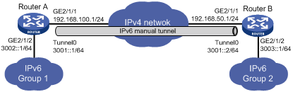
As shown in Figure 5, two IPv6 networks are connected over an IPv4 network. Configure an IPv6 manual tunnel between Router A and Router B to make the two IPv6 networks reachable to each other. If the destination IPv4 address cannot be automatically obtained from the destination IPv6 addresses of packets, configure an IPv6 manual tunnel.
Configuration procedure
|
|
NOTE: Before configuring an IPv6 manual tunnel, make sure that Router A and Router B are reachable to each other. |
· Configure Router A:
# Enable IPv6.
<RouterA> system-view
[RouterA] ipv6
# Configure an IPv4 address for GigabitEthernet 2/1/1.
[RouterA] interface GigabitEthernet 2/1/1
[RouterA-GigabitEthernet2/1/1] ip address 192.168.100.1 255.255.255.0
[RouterA-GigabitEthernet2/1/1] quit
# Configure an IPv6 address for GigabitEthernet 2/1/2.
[RouterA] interface GigabitEthernet 2/1/2
[RouterA-GigabitEthernet2/1/2] ipv6 address 3002::1 64
[RouterA-GigabitEthernet2/1/2] quit
# Configure an IPv6 manual tunnel.
[RouterA] interface tunnel 0
[RouterA-Tunnel0] ipv6 address 3001::1/64
[RouterA-Tunnel0] source GigabitEthernet 2/1/1
[RouterA-Tunnel0] destination 192.168.50.1
[RouterA-Tunnel0] tunnel-protocol ipv6-ipv4
[RouterA-Tunnel0] quit
# Configure a static route to IPv6 Group 2 through tunnel 0 on Router A.
[RouterA] ipv6 route-static 3003:: 64 tunnel 0
· Configure Router B:
# Enable IPv6.
<RouterB> system-view
[RouterB] ipv6
# Configure an IPv4 address for GigabitEthernet 2/1/1.
[RouterB] interface GigabitEthernet 2/1/1
[RouterB-GigabitEthernet2/1/1] ip address 192.168.50.1 255.255.255.0
[RouterB-GigabitEthernet2/1/1] quit
# Configure an IPv6 address for GigabitEthernet 2/1/2.
[RouterA] interface GigabitEthernet 2/1/2
[RouterA-GigabitEthernet2/1/2] ipv6 address 3003::1 64
[RouterA-GigabitEthernet2/1/2] quit
# Configure an IPv6 manual tunnel.
[RouterB] interface tunnel 0
[RouterB-Tunnel0] ipv6 address 3001::2/64
[RouterB-Tunnel0] source GigabitEthernet 2/1/1
[RouterB-Tunnel0] destination 192.168.100.1
[RouterB-Tunnel0] tunnel-protocol ipv6-ipv4
[RouterB-Tunnel0] quit
# Configure a static route to IPv6 Group 1 through tunnel 0 on Router B.
[RouterB] ipv6 route-static 3002:: 64 tunnel 0
Verifying the configuration
[RouterA] display ipv6 interface tunnel 0 verbose
Tunnel0 current state :UP
Line protocol current state :UP
IPv6 is enabled, link-local address is FE80::C0A8:6401
Global unicast address(es):
3001::1, subnet is 3001::/64
Joined group address(es):
FF02::1:FF00:0
FF02::1:FF00:1
FF02::1:FFA8:6401
FF02::2
FF02::1
MTU is 1480 bytes
ND reachable time is 30000 milliseconds
ND retransmit interval is 1000 milliseconds
Hosts use stateless autoconfig for addresses
IPv6 Packet statistics:
InReceives: 55
……(omitted)
[RouterB] display ipv6 interface tunnel 0 verbose
Tunnel0 current state :UP
Line protocol current state :UP
IPv6 is enabled, link-local address is FE80::C0A8:3201
Global unicast address(es):
3001::2, subnet is 3001::/64
Joined group address(es):
FF02::1:FF00:0
FF02::1:FF00:1
FF02::1:FFA8:3201
FF02::2
FF02::1
MTU is 1480 bytes
ND reachable time is 30000 milliseconds
ND retransmit interval is 1000 milliseconds
Hosts use stateless autoconfig for addresses
IPv6 Packet statistics:
InReceives: 55
……(omitted)
# Ping the IPv6 address of the peer interface GigabitEthernet 2/1/2 from Router A:
[RouterA] ping ipv6 3003::1
PING 3003::1 : 56 data bytes, press CTRL_C to break
Reply from 3003::1
bytes=56 Sequence=1 hop limit=64 time = 1 ms
Reply from 3003::1
bytes=56 Sequence=2 hop limit=64 time = 1 ms
Reply from 3003::1
bytes=56 Sequence=3 hop limit=64 time = 1 ms
Reply from 3003::1
bytes=56 Sequence=4 hop limit=64 time = 1 ms
Reply from 3003::1
bytes=56 Sequence=5 hop limit=64 time = 1 ms
--- 3003::1 ping statistics ---
5 packet(s) transmitted
5 packet(s) received
0.00% packet loss
round-trip min/avg/max = 1/1/1 ms
Configuring an automatic IPv4-compatible IPv6 tunnel
Configuration prerequisites
Configure IP addresses for interfaces (such as the VLAN interface, Ethernet interface, and loopback interface) on the router to ensure normal communication. One of the interfaces will be used as the source interface of the tunnel.
Configuration guidelines
When you configure an automatic IPv4-compatible IPv6 tunnel, follow these guidelines:
· No destination address needs to be configured for an automatic IPv4-compatible IPv6 tunnel. The destination address of the tunnel can be automatically obtained through the IPv4 address embedded in the IPv4-compatible IPv6 address.
· The automatic tunnel interfaces encapsulated with the same protocol cannot share the same source IP address.
Configuration procedure
To configure an automatic IPv4-compatible IPv6 tunnel:
|
Step |
Command |
Remarks |
|
1. Enter system view. |
system-view |
N/A |
|
2. Enable the IPv6 packet forwarding function. |
ipv6 |
By default, the IPv6 packet forwarding function is disabled. |
|
3. Enter tunnel interface view. |
interface tunnel number |
N/A |
|
4. Configure an IPv6 address for the tunnel interface. |
· Configure an IPv6 global unicast address or site-local address: ¡ ipv6 address { ipv6-address prefix-length | ipv6-address | prefix-length } ¡ ipv6 address ipv6-address | prefix-length eui-64 · Configure an IPv6 link-local address: a. ipv6 address auto link-local b. ipv6 address ipv6-address link-local |
Use either the ipv6 address { ipv6-address prefix-length | ipv6-address | prefix-length } or the ipv6 address ipv6-address | prefix-length eui-64 command to configure an IPv6 global unicast address or site-local address. By default, · No IPv6 global unicast address or site-local address is configured for the tunnel interface. · A link-local address will automatically be generated when an IPv6 global unicast or site-local address is configured for the interface. The IPv6 link-local address configuration is otional. |
|
5. Configure an automatic IPv4-compatible IPv6 tunnel. |
tunnel-protocol ipv6-ipv4 auto-tunnel |
By default, the tunnel is a GRE over IPv4 tunnel. The same tunnel type should be configured at both ends of the tunnel. Otherwise, packet delivery will fail. |
|
6. Configure a source address or interface for the tunnel. |
source { ip-address | interface-type interface-number } |
By default, no source address or interface is configured for the tunnel. |
Configuration example
Network requirements
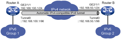
As shown in Figure 6, dual-stack routers, Router A and Router B are connected over an IPv4 network. Configure an automatic IPv4-compatible IPv6 tunnel between the two routers to enable the IPv6 networks to communicate with each other over the tunnel.
Configuration procedure
|
|
NOTE: Before configuring an automatic IPv4-compatible IPv6 tunnel, make sure that Router A and Router B are reachable to each other. |
· Configure Router A:
# Enable IPv6.
<RouterA> system-view
[RouterA] ipv6
# Configure an IP address for GigabitEthernet 2/1/1.
[RouterA] interface GigabitEthernet 2/1/1
[RouterA-GigabitEthernet2/1/1] ip address 192.168.100.1 255.255.255.0
[RouterA-GigabitEthernet2/1/1] quit
# Configure an automatic IPv4-compatible IPv6 tunnel.
[RouterA] interface tunnel 0
[RouterA-Tunnel0] ipv6 address ::192.168.100.1/96
[RouterA-Tunnel0] source GigabitEthernet 2/1/1
[RouterA-Tunnel0] tunnel-protocol ipv6-ipv4 auto-tunnel
· Configure Router B:
# Enable IPv6.
<RouterB> system-view
[RouterB] ipv6
# Configure an IP address for GigabitEthernet 2/1/1.
[RouterB] interface GigabitEthernet 2/1/1
[RouterB-GigabitEthernet2/1/1] ip address 192.168.50.1 255.255.255.0
[RouterB-GigabitEthernet2/1/1] quit
# Configure an automatic IPv4-compatible IPv6 tunnel.
[RouterB] interface tunnel 0
[RouterB-Tunnel0] ipv6 address ::192.168.50.1/96
[RouterB-Tunnel0] source GigabitEthernet 2/1/1
[RouterB-Tunnel0] tunnel-protocol ipv6-ipv4 auto-tunnel
Verifying the configuration
After the above configurations, display the status of the tunnel interfaces on Router A and Router B, respectively.
[RouterA] display ipv6 interface tunnel 0 verbose
Tunnel0 current state :UP
Line protocol current state :UP
IPv6 is enabled, link-local address is FE80::C0A8:6401
Global unicast address(es):
::192.168.100.1, subnet is ::/96
Joined group address(es):
FF02::1:FFA8:6401
FF02::1:FF00:0
FF02::2
FF02::1
MTU is 1480 bytes
ND reachable time is 30000 milliseconds
ND retransmit interval is 1000 milliseconds
Hosts use stateless autoconfig for addresses
IPv6 Packet statistics:
InReceives: 65
……(omitted)
[RouterB] display ipv6 interface tunnel 0 verbose
Tunnel0 current state :UP
Line protocol current state :UP
IPv6 is enabled, link-local address is FE80::C0A8:3201
Global unicast address(es):
::192.168.50.1, subnet is ::/96
Joined group address(es):
FF02::1:FFA8:3201
FF02::1:FF00:0
FF02::2
FF02::1
MTU is 1480 bytes
ND reachable time is 30000 milliseconds
ND retransmit interval is 1000 milliseconds
Hosts use stateless autoconfig for addresses
IPv6 Packet statistics:
InReceives: 65
……(omitted)
# Ping the IPv4-compatible IPv6 address of the peer tunnel interface from Router A.
[RouterA] ping ipv6 ::192.168.50.1
PING ::192.168.50.1 : 56 data bytes, press CTRL_C to break
Reply from ::192.168.50.1
bytes=56 Sequence=1 hop limit=64 time = 1 ms
Reply from ::192.168.50.1
bytes=56 Sequence=2 hop limit=64 time = 1 ms
Reply from ::192.168.50.1
bytes=56 Sequence=3 hop limit=64 time = 1 ms
Reply from ::192.168.50.1
bytes=56 Sequence=4 hop limit=64 time = 1 ms
Reply from ::192.168.50.1
bytes=56 Sequence=5 hop limit=64 time = 1 ms
--- ::192.168.50.1 ping statistics ---
5 packet(s) transmitted
5 packet(s) received
0.00% packet loss
round-trip min/avg/max = 1/1/1 ms
Configuring a 6to4 tunnel
Configuration prerequisites
Configure IP addresses for interfaces (such as the VLAN interface, Ethernet interface, and loopback interface) on the router to ensure normal communication. One of the interfaces will be used as the source interface of the tunnel.
Configuration guidelines
When you configure a 6to4 tunnel, follow these guidelines:
· No destination address needs to be configured for a 6to4 tunnel because the destination address can automatically be obtained from the IPv4 address embedded in the 6to4 IPv6 address.
· To encapsulate and forward IPv6 packets whose destination address does not belong to the network segment where the receiving tunnel interface resides, you need to configure a static route to reach the destination IPv6 address through this tunnel interface on the router. Because automatic tunnels do not support dynamic routing, you can configure a static route to that destination IPv6 address with this tunnel interface as the outbound interface or the peer tunnel interface address as the next hop. A similar configuration needs to be performed at the other tunnel end. For the detailed configuration, see Layer 3—IP Routing Configuration Guide.
· The automatic tunnel interfaces using the same encapsulation protocol cannot share the same source IP address.
Configuration procedure
To configure a 6to4 tunnel:
|
Step |
Command |
Remarks |
|
1. Enter system view. |
system-view |
N/A |
|
2. Enable IPv6. |
ipv6 |
By default, the IPv6 packet forwarding function is disabled. |
|
3. Enter tunnel interface view. |
interface tunnel number |
N/A |
|
4. Configure an IPv6 address for the tunnel interface. |
· Configure an IPv6 global unicast address or site-local address: ¡ ipv6 address { ipv6-address prefix-length | ipv6-address | prefix-length } ¡ ipv6 address ipv6-address | prefix-length eui-64 · Configure an IPv6 link-local address: a. ipv6 address auto link-local b. ipv6 address ipv6-address link-local |
Use either the ipv6 address { ipv6-address prefix-length | ipv6-address | prefix-length } or the ipv6 address ipv6-address | prefix-length eui-64 command to configure an IPv6 global unicast address or site-local address. By default, · No IPv6 global unicast address or site-local address is configured for the tunnel interface. · A link-local address will automatically be generated when an IPv6 global unicast address or site-local address is configured. The IPv6 link-local address configuration is optional. |
|
5. Specify the 6to4 tunnel mode. |
tunnel-protocol ipv6-ipv4 6to4 |
By default, the tunnel is a GRE over IPv4 tunnel. The same tunnel type should be configured at both ends of the tunnel. Otherwise, packet delivery will fail. |
|
6. Configure a source address or interface for the tunnel. |
source { ip-address | interface-type interface-number } |
By default, no source address or interface is configured for the tunnel. |
|
7. Return to system view. |
quit |
N/A |
|
8. Enable dropping of IPv6 packets using IPv4-compatible IPv6 addresses. |
tunnel discard ipv4-compatible-packet |
Optional. Disabled by default. |
6to4 tunnel configuration example
Network requirements
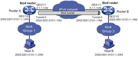
As shown in Figure 7, two 6to4 networks are connected to an IPv4 network through two 6to4 routers (Router A and Router B) respectively. Configure a 6to4 tunnel to make Host A and Host B reachable to each other.
To enable communication between 6to4 networks, you need to configure 6to4 addresses for 6to4 routers and hosts in the 6to4 networks.
· The IPv4 address of GigabitEthernet 2/1/1 on Router A is 2.1.1.1/24, and the corresponding 6to4 prefix is 2002:0201:0101::/48 after it is translated to an IPv6 address. Assign interface tunnel 0 to subnet 2002:0201:0101::/64 and GigabitEthernet 2/1/2 to subnet 2002:0201:0101:1::/64.
· The IPv4 address of GigabitEthernet 2/1/1 on Router B is 5.1.1.1/24, and the corresponding 6to4 prefix is 2002:0501:0101::/48 after it is translated to an IPv6 address. Assign interface tunnel 0 to subnet 2002:0501:0101::/64 and GigabitEthernet 2/1/2 to subnet 2002:0501:0101:1::/64.
Configuration procedure
|
|
NOTE: Before configuring a 6to4 tunnel, make sure that Router A and Router B are reachable to each other. |
· Configure Router A:
# Enable IPv6.
<RouterA> system-view
[RouterA] ipv6
# Configure an IPv4 address for GigabitEthernet 2/1/1.
[RouterA] interface GigabitEthernet 2/1/1
[RouterA-GigabitEthernet2/1/1] ip address 2.1.1.1 24
[RouterA-GigabitEthernet2/1/1] quit
# Configure an IPv6 address for GigabitEthernet 2/1/2.
[RouterA] interface GigabitEthernet 2/1/2
[RouterA-GigabitEthernet2/1/2] ipv6 address 2002:0201:0101:1::1/64
[RouterA-GigabitEthernet2/1/2] quit
# Configure the 6to4 tunnel.
[RouterA] interface tunnel 0
[RouterA-Tunnel0] ipv6 address 2002:201:101::1/64
[RouterA-Tunnel0] source GigabitEthernet 2/1/1
[RouterA-Tunnel0] tunnel-protocol ipv6-ipv4 6to4
[RouterA-Tunnel0] quit
# Configure a static route whose destination address is 2002::/16 and next-hop is the tunnel interface.
[RouterA] ipv6 route-static 2002:: 16 tunnel 0
· Configure Router B:
# Enable IPv6.
<RouterB> system-view
[RouterB] ipv6
# Configure an IPv6 address for GigabitEthernet 2/1/1.
[RouterB] interface GigabitEthernet 2/1/1
[RouterB-GigabitEthernet2/1/1] ip address 5.1.1.1 24
[RouterB-GigabitEthernet2/1/1] quit
# Configure an IPv6 address for GigabitEthernet 2/1/2.
[RouterB] interface GigabitEthernet 2/1/2
[RouterB-GigabitEthernet2/1/2] ipv6 address 2002:0501:0101:1::1/64
[RouterB-GigabitEthernet2/1/2] quit
# Configure a 6to4 tunnel.
[RouterB] interface tunnel 0
[RouterB-Tunnel0] ipv6 address 2002:0501:0101::1/64
[RouterB-Tunnel0] source GigabitEthernet 2/1/1
[RouterB-Tunnel0] tunnel-protocol ipv6-ipv4 6to4
[RouterB-Tunnel0] quit
# Configure a static route whose destination address is 2002::/16 and next-hop is the tunnel interface.
[RouterB] ipv6 route-static 2002:: 16 tunnel 0
Verifying the configuration
After the above configuration, ping Host B from Host A or ping Host A from Host B.
D:\>ping6 -s 2002:201:101:1::2 2002:501:101:1::2
Pinging 2002:501:101:1::2
from 2002:201:101:1::2 with 32 bytes of data:
Reply from 2002:501:101:1::2: bytes=32 time=13ms
Reply from 2002:501:101:1::2: bytes=32 time=1ms
Reply from 2002:501:101:1::2: bytes=32 time=1ms
Reply from 2002:501:101:1::2: bytes=32 time<1ms
Ping statistics for 2002:501:101:1::2:
Packets: Sent = 4, Received = 4, Lost = 0 (0% loss),
Approximate round trip times in milli-seconds:
Minimum = 0ms, Maximum = 13ms, Average = 3ms
6to4 relay configuration example
Network requirements
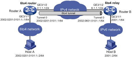
As shown in Figure 8, Router A is a 6to4 router, and 6to4 addresses are used on the connected IPv6 network. Router B serves as a 6to4 relay router and is connected to the IPv6 network (2001::/16). Configure a 6to4 tunnel between Router A and Router B to make Host A and Host B reachable to each other.
Configuration procedure
|
|
NOTE: · Before configuring a 6to4 relay, make sure that Router A and Router B are reachable to each other. · The configuration on a 6to4 relay router is similar to that on a 6to4 router. However, to enable communication between the 6to4 network and the IPv6 network, you need to configure a route to the IPv6 network on the 6to4 router. |
· Configure Router A:
# Enable IPv6.
<RouterA> system-view
[RouterA] ipv6
# Configure an IPv4 address for GigabitEthernet 3/1/2.
[RouterA] interface GigabitEthernet 3/1/2
[RouterA-GigabitEthernet3/1/2] ip address 2.1.1.1 255.255.255.0
[RouterA-GigabitEthernet3/1/2] quit
# Configure an IPv6 address for GigabitEthernet 3/1/1.
[RouterA] interface GigabitEthernet 3/1/1
[RouterA-GigabitEthernet3/1/1] ipv6 address 2002:0201:0101:1::1/64
[RouterA-GigabitEthernet3/1/1] quit
# Configure a 6to4 tunnel.
[RouterA] interface tunnel 0
[RouterA-Tunnel0] ipv6 address 2002:0201:0101::1/64
[RouterA-Tunnel0] source GigabitEthernet 3/1/2
[RouterA-Tunnel0] tunnel-protocol ipv6-ipv4 6to4
[RouterA-Tunnel0] quit
# Configure a static route to the 6to4 relay router.
[RouterA] ipv6 route-static 2002:0601:0101:: 64 tunnel 0
# Configure the default route to the IPv6-only network.
[RouterA] ipv6 route-static :: 0 2002:0601:0101::1
· Configure Router B:
# Enable IPv6.
<RouterB> system-view
[RouterB] ipv6
# Configure an IPv4 address for GigabitEthernet 3/1/2.
[RouterB] interface GigabitEthernet 3/1/2
[RouterB-GigabitEthernet3/1/2] ip address 6.1.1.1 255.255.255.0
[RouterB-GigabitEthernet3/1/2] quit
# Configure an IPv6 address for GigabitEthernet 3/1/1.
[RouterB] interface GigabitEthernet 3/1/1
[RouterB-GigabitEthernet3/1/1] ipv6 address 2001::1/16
[RouterB-GigabitEthernet3/1/1] quit
# Configure a 6to4 tunnel.
[RouterB] interface tunnel 0
[RouterB-Tunnel0] ipv6 address 2002:0601:0101::1/64
[RouterB-Tunnel0] source GigabitEthernet 3/1/2
[RouterB-Tunnel0] tunnel-protocol ipv6-ipv4 6to4
[RouterB-Tunnel0] quit
# Configure a static route whose destination address is 2002::/16 and next-hop is the tunnel interface.
[RouterB] ipv6 route-static 2002:: 16 tunnel 0
Verifying the configuration
After the above configuration, ping Host B from Host A.
D:\>ping6 -s 2002:201:101:1::2 2001::2
Pinging 2001::2
from 2002:201:101:1::2 with 32 bytes of data:
Reply from 2001::2: bytes=32 time=13ms
Reply from 2001::2: bytes=32 time=1ms
Reply from 2001::2: bytes=32 time=1ms
Reply from 2001::2: bytes=32 time<1ms
Ping statistics for 2001::2:
Packets: Sent = 4, Received = 4, Lost = 0 (0% loss),
Approximate round trip times in milli-seconds:
Minimum = 0ms, Maximum = 13ms, Average = 3ms
Configuring an ISATAP tunnel
Configuration prerequisites
Configure IP addresses for interfaces (such as the VLAN interface, Ethernet interface, and loopback interface) on the router to ensure normal communication. One of the interfaces will be used as the source interface of the tunnel.
Configuration guidelines
When you configure an ISATAP tunnel, follow these guidelines:
· No destination address needs to be configured for an ISATAP tunnel. The destination address of the tunnel can be automatically obtained through the IPv4 address embedded in the ISATAP address.
· To encapsulate and forward IPv6 packets whose destination address does not belong to the network segment where the receiving tunnel interface resides, you need to configure a static route to reach the destination IPv6 address through this tunnel interface on the router. Because automatic tunnels do not support dynamic routing, you can configure a static route to that destination IPv6 address with this tunnel interface as the outbound interface or the peer tunnel interface address as the next hop. A similar configuration needs to be performed at the other tunnel end. For more configuration information, see Layer 3—IP Routing Configuration Guide.
· The automatic tunnel interfaces using the same encapsulation protocol cannot share the same source IP address.
Configuration procedure
To configure an ISATAP tunnel:
|
Step |
Command |
Remarks |
|
1. Enter system view. |
system-view |
N/A |
|
2. Enable IPv6. |
ipv6 |
By default, the IPv6 forwarding function is disabled. |
|
3. Enter tunnel interface view. |
interface tunnel number |
N/A |
|
4. Configure an IPv6 address for the tunnel interface. |
· Configure an IPv6 global unicast address or site-local address: ¡ ipv6 address { ipv6-address prefix-length | ipv6-address | prefix-length } ¡ ipv6 address ipv6-address | prefix-length eui-64 · Configure an IPv6 link-local address: a. ipv6 address auto link-local b. ipv6 address ipv6-address link-local |
Use either the ipv6 address { ipv6-address prefix-length | ipv6-address | prefix-length } or the ipv6 address ipv6-address | prefix-length eui-64 command to configure an IPv6 global unicast address or site-local address. By default, · No IPv6 global unicast address is configured for the tunnel interface. · A link-local address will automatically be generated when an IPv6 global unicast address or link-local address is configured. The IPv6 link-local address configuration is optional. |
|
5. Specify the ISATAP tunnel mode. |
tunnel-protocol ipv6-ipv4 isatap |
By default, the tunnel is a GRE over IPv4 tunnel. The same tunnel type should be configured at both ends of the tunnel. Otherwise, packet delivery will fail. |
|
6. Configure a source address or interface for the tunnel. |
source { ip-address | interface-type interface-number } |
By default, no source address or interface is configured for the tunnel. |
|
7. Return to system view. |
quit |
N/A |
|
8. Enable dropping of IPv6 packets using IPv4-compatible IPv6 addresses. |
tunnel discard ipv4-compatible-packet |
Optional. Disabled by default. |
Configuration example
Network requirements
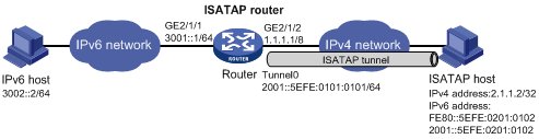
As shown in Figure 9, an IPv6 network is connected to an IPv4 network through an ISATAP router. Configure the ISATAP tunnel to enable the IPv6 host in the IPv4 network to access the IPv6 network.
Configuration procedure
|
|
NOTE: Before configuring an ISATAP tunnel, make sure that GigabitEthernet 2/1/2 on the ISATAP router and the ISATAP host are reachable to each other. |
· Configure the ISATAP router:
# Enable IPv6.
<Router> system-view
[Router] ipv6
# Configure addresses for interfaces.
[Router] interface GigabitEthernet 2/1/1
[Router-GigabitEthernet2/1/1] ipv6 address 3001::1/64
[Router-GigabitEthernet2/1/1] quit
[Router] interface GigabitEthernet 2/1/2
[Router-GigabitEthernet2/1/2] ip address 1.1.1.1 255.0.0.0
[Router-GigabitEthernet2/1/2] quit
# Configure an ISATAP tunnel.
[Router] interface tunnel 0
[Router-Tunnel0] ipv6 address 2001::5efe:0101:0101 64
[Router-Tunnel0] source GigabitEthernet 2/1/2
[Router-Tunnel0] tunnel-protocol ipv6-ipv4 isatap
# Disable the RA suppression so that hosts can acquire information such as the address prefix from the RA message released by the ISATAP router.
[Router-Tunnel0] undo ipv6 nd ra halt
[Router-Tunnel0] quit
# Configure a static route to the ISATAP host.
[Router] ipv6 route-static 2001:: 16 tunnel 0
· Configure the ISATAP host:
The specific configuration on the ISATAP host is related to its operating system. The following example shows the configuration of the host running the Windows XP.
# Install IPv6.
C:\>ipv6 install
# On a Windows XP-based host, the ISATAP interface is usually interface 2. Configure the IPv4 address of the ISATAP router on interface 2 to complete the configuration on the host. Before that, display information on the ISATAP interface:
C:\>ipv6 if 2
Interface 2: Automatic Tunneling Pseudo-Interface
Guid {48FCE3FC-EC30-E50E-F1A7-71172AEEE3AE}
does not use Neighbor Discovery
does not use Router Discovery
routing preference 1
EUI-64 embedded IPv4 address: 0.0.0.0
router link-layer address: 0.0.0.0
preferred link-local fe80::5efe:2.1.1.2, life infinite
link MTU 1280 (true link MTU 65515)
current hop limit 128
reachable time 42500ms (base 30000ms)
retransmission interval 1000ms
DAD transmits 0
default site prefix length 48
# A link-local address (fe80::5efe:2.1.1.2) in the ISATAP format was automatically generated for the ISATAP interface. Configure the IPv4 address of the ISATAP router on the ISATAP interface.
C:\>ipv6 rlu 2 1.1.1.1
After carrying out the above command, look at the information on the ISATAP interface.
C:\>ipv6 if 2
Interface 2: Automatic Tunneling Pseudo-Interface
Guid {48FCE3FC-EC30-E50E-F1A7-71172AEEE3AE}
does not use Neighbor Discovery
uses Router Discovery
routing preference 1
EUI-64 embedded IPv4 address: 2.1.1.2
router link-layer address: 1.1.1.1
preferred global 2001::5efe:2.1.1.2, life 29d23h59m46s/6d23h59m46s (public)
preferred link-local fe80::5efe:2.1.1.2, life infinite
link MTU 1500 (true link MTU 65515)
current hop limit 255
reachable time 42500ms (base 30000ms)
retransmission interval 1000ms
DAD transmits 0
default site prefix length 48
# By comparison, it is found that the host acquires the address prefix 2001::/64 and automatically generates the address 2001::5efe:2.1.1.2. Meanwhile, “uses Router Discovery” is displayed, indicating that the router discovery function is enabled on the host. At this time, ping the IPv6 address of the tunnel interface of the router. If the address is successfully pinged, an ISATAP tunnel is established.
C:\>ping 2001::5efe:1.1.1.1
Pinging 2001::5efe:1.1.1.1 with 32 bytes of data:
Reply from 2001::5efe:1.1.1.1: time=1ms
Reply from 2001::5efe:1.1.1.1: time=1ms
Reply from 2001::5efe:1.1.1.1: time=1ms
Reply from 2001::5efe:2.1.1.1: time=1ms
Ping statistics for 2001::5efe:1.1.1.1:
Packets: Sent = 4, Received = 4, Lost = 0 (0% loss),
Approximate round trip times in milli-seconds:
Minimum = 1ms, Maximum = 1ms, Average = 1ms
Verifying the configuration
After the above configuration, the ISATAP host can access the host in the IPV6 network.
Configuring an IPv4 over IPv4 tunnel
Configuration prerequisites
Configure IP addresses for interfaces (such as the VLAN interface, Ethernet interface, and loopback interface) on the router to ensure normal communication. One of the interfaces will be used as the source interface of the tunnel.
Configuration guidelines
When you configure an IPv4 over IPv4 tunnel, follow these guidelines:
· The router does not support IPv4 over IPv4 tunnels when working in hybrid or SPC mode. For more information about the system working modes, see Fundamentals Configuration Guide.
· To encapsulate and forward IPv4 packets whose destination address does not belong to the network segment where the receiving tunnel interface resides, you need to configure a static route or dynamic routing for forwarding those packets through this tunnel interface. If you configure a static route to that destination IPv4 address, specify this tunnel interface as the outbound interface, or the peer tunnel interface address as the next hop. A similar configuration needs to be performed at the other tunnel end. If you configure dynamic routing at both ends, enable the dynamic routing protocol on both tunnel interfaces. For the detailed configuration, see Layer 3—IP Routing Configuration Guide.
· The IPv4 address and the destination address of a tunnel interface cannot be in the same network segment.
· The destination address of a route with a tunnel interface as the egress interface and the destination address of the tunnel interface must not be in the same network segment.
· Two or more tunnel interfaces using the same encapsulation protocol must have different source and destination addresses.
· If you specify a source interface instead of a source address for the tunnel, the source address of the tunnel is the primary IP address of the source interface.
Configuration procedure
To configure an IPv4 over IPv4 tunnel:
|
Step |
Command |
Remarks |
|
1. Enter system view. |
system-view |
N/A |
|
2. Enter tunnel interface view. |
interface tunnel number |
N/A |
|
3. Configure an IPv4 address for the tunnel interface. |
ip address ip-address { mask | mask-length } [ sub ] |
By default, no IPv4 address is configured for the tunnel interface. |
|
4. Specify the IPv4 over IPv4 tunnel mode. |
tunnel-protocol ipv4-ipv4 |
Optional. By default, the tunnel is a GRE over IPv4 tunnel. The same tunnel type should be configured at both ends of the tunnel. Otherwise, packet delivery will fail. |
|
5. Configure a source address or interface for the tunnel. |
source { ip-address | interface-type interface-number } |
By default, no source address or interface is configured for the tunnel. |
|
6. Configure a destination address for the tunnel. |
destination ip-address |
By default, no destination address is configured for the tunnel. |
Configuration example
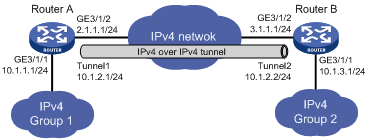
Network requirements
As shown in Figure 10, the two IPv4 subnets Group 1 and Group 2 use private IPv4 addresses. Configure an IPv4 over IPv4 tunnel between Router A and Router B to make the two subnets reachable to each other.
Configuration procedure
|
|
NOTE: Before configuring an IPv4 over IPv4 tunnel, make sure that Router A and Router B are reachable to each other. |
· Configure Router A:
# Configure an IPv4 address for GigabitEthernet 3/1/1.
<RouterA> system-view
[RouterA] interface GigabitEthernet 3/1/1
[RouterA-GigabitEthernet3/1/1] ip address 10.1.1.1 255.255.255.0
[RouterA-GigabitEthernet3/1/1] quit
# Configure an IPv4 address for GigabitEthernet 3/1/2 (the physical interface of the tunnel).
<RouterA> system-view
[RouterA] interface GigabitEthernet 3/1/2
[RouterA-GigabitEthernet3/1/2] ip address 2.1.1.1 255.255.255.0
[RouterA-GigabitEthernet3/1/2] quit
# Create the interface tunnel 1.
[RouterA] interface tunnel 1
# Configure an IPv4 address for the interface tunnel 1.
[RouterA-Tunnel1] ip address 10.1.2.1 255.255.255.0
# Configure the tunnel encapsulation mode.
[RouterA-Tunnel1] tunnel-protocol ipv4-ipv4
# Configure a source address for the interface tunnel 1 (IP address of VLAN-interface 100).
[RouterA-Tunnel1] source 2.1.1.1
# Configure a destination address for the interface tunnel 1 (IP address of VLAN-interface 100 of Router B).
[RouterA-Tunnel1] destination 3.1.1.1
[RouterA-Tunnel1] quit
# Configure a static route from Router A through the interface tunnel 1 to Group 2.
[RouterA] ip route-static 10.1.3.0 255.255.255.0 tunnel 1
· Configure Router B:
# Configure an IPv4 address for GigabitEthernet 3/1/1.
<RouterB> system-view
[RouterB] interface GigabitEthernet 3/1/1
[RouterB-GigabitEthernet3/1/1] ip address 10.1.3.1 255.255.255.0
[RouterB-GigabitEthernet3/1/1] quit
# Configure an IPv4 address for GigabitEthernet 3/1/2 (the physical interface of the tunnel).
<RouterA> system-view
[RouterA] interface GigabitEthernet 3/1/2
[RouterA-GigabitEthernet3/1/2] ip address 3.1.1.1 255.255.255.0
[RouterA-GigabitEthernet3/1/2] quit
# Create the interface tunnel 2.
[RouterB] interface tunnel 2
# Configure an IPv4 address for the interface tunnel 2.
[RouterB-Tunnel2] ip address 10.1.2.2 255.255.255.0
# Configure the tunnel encapsulation mode.
[RouterB-Tunnel2] tunnel-protocol ipv4-ipv4
# Configure the source address for the interface tunnel 2 (IP address of VLAN-interface 100).
[RouterB-Tunnel2] source 3.1.1.1
# Configure a destination address for the interface tunnel 2 (IP address of VLAN-interface 100 of Router A).
[RouterB-Tunnel2] destination 2.1.1.1
[RouterB-Tunnel2] quit
# Configure a static route from Router B through the interface tunnel 2 to Group 1.
[RouterB] ip route-static 10.1.1.0 255.255.255.0 tunnel 2
Verifying the configuration
After the above configuration, display the status of the tunnel interfaces on Router A and Router B, respectively.
<RouterA> display interface tunnel 1
Tunnel1 current state: UP
Line protocol current state: UP
Description: Tunnel1 Interface
The Maximum Transmit Unit is 64000
Internet Address is 10.1.2.1/24 Primary
Encapsulation is TUNNEL, aggregation ID not set
Tunnel source 2.1.1.1, destination 3.1.1.1
Tunnel protocol/transport IP/IP
Last 300 seconds input: 0 bytes/sec, 0 packets/sec
Last 300 seconds output: 0 bytes/sec, 0 packets/sec
0 packets input, 0 bytes
0 input error
0 packets output, 0 bytes
0 output error
<RouterB> display interface tunnel 2
Tunnel2 current state: UP
Line protocol current state: UP
Description: Tunnel2 Interface
The Maximum Transmit Unit is 64000
Internet Address is 10.1.2.2/24 Primary
Encapsulation is TUNNEL, aggregation ID not set
Tunnel source 3.1.1.1, destination 2.1.1.1
Tunnel protocol/transport IP/IP
Last 300 seconds input: 0 bytes/sec, 0 packets/sec
Last 300 seconds output: 0 bytes/sec, 0 packets/sec
0 packets input, 0 bytes
0 input error
0 packets output, 0 bytes
0 output error
# Ping the IPv4 address of the peer interface GigabitEthernet 3/1/1 from Router A.
[RouterA] ping 10.1.3.1
PING 10.1.3.1: 56 data bytes, press CTRL_C to break
Reply from 10.1.3.1: bytes=56 Sequence=1 ttl=255 time=15 ms
Reply from 10.1.3.1: bytes=56 Sequence=2 ttl=255 time=15 ms
Reply from 10.1.3.1: bytes=56 Sequence=3 ttl=255 time=16 ms
Reply from 10.1.3.1: bytes=56 Sequence=4 ttl=255 time=16 ms
Reply from 10.1.3.1: bytes=56 Sequence=5 ttl=255 time=15 ms
--- 10.1.3.1 ping statistics ---
5 packet(s) transmitted
5 packet(s) received
0.00% packet loss
round-trip min/avg/max = 15/15/16 ms
Displaying and maintaining tunneling configuration
|
Task |
Command |
Remarks |
|
Display information about a specified tunnel interface. |
display interface [ tunnel ] [ brief [ down ] ] [ | { begin | exclude | include } regular-expression ] display interface tunnel number [ brief ] [ | { begin | exclude | include } regular-expression ] |
Available in any view |
|
Display IPv6 information on tunnel interfaces. |
display ipv6 interface tunnel [ number ] [ verbose ] [ | { begin | exclude | include } regular-expression ] |
Available in any view |
|
Clear statistics on tunnel interfaces. |
reset counters interface [ tunnel [ number ] ] |
Available in any view |
Troubleshooting tunneling configuration
Symptom
After the configuration of related parameters such as tunnel source address, tunnel destination address, and tunnel type, the tunnel interface is still not up.
Solution
To solve the problem:
1. The common cause is that the physical interface of the tunnel source is not up. Use the display interface tunnel or display ipv6 interface tunnel commands to view whether the physical interface of the tunnel source is up. If the physical interface is down, check the network connections.
2. Another possible cause is that the tunnel destination is unreachable. Use the display ipv6 routing-table or display ip routing-table command to view whether the tunnel destination is reachable. If no routing entry is available for tunnel communication in the routing table, configure related routes.