- Table of Contents
-
- 05-Layer 3 - IP Services Configuration Guide
- 00-Preface
- 01-ARP Configuration
- 02-IP Addressing Configuration
- 03-DHCP Configuration
- 04-DNS Configuration
- 05-NAT Configuration
- 06-IP Performance Optimization Configuration
- 07-Adjacency Table Configuration
- 08-UDP Helper Configuration
- 09-IPv6 Basics Configuration
- 10-DHCPv6 Configuration
- 11-IPv6 DNS Configuration
- 12-NAT-PT Configuration
- 13-Tunneling Configuration
- 14-GRE Configuration
- Related Documents
-
| Title | Size | Download |
|---|---|---|
| 05-NAT Configuration | 381.74 KB |
Contents
Configuring address translation
Introduction to address translation
Configuring an internal server
Introduction to internal server
Configuring a common internal server
Configuring load shared internal servers
Binding a NAT-enabled interface to the NAT service interface
Creating a connection limit policy
Configuring the connection limit policy
Applying the connection limit policy
Enabling connection limit logging
Displaying and maintaining NAT
One-to-one static NAT configuration example
Dynamic NAT configuration example I
Dynamic NAT configuration example II
Dynamic NAT configuration example III
Dynamic NAT configuration example IV
Common internal server configuration example
Load sharing internal server configuration example
NAT DNS mapping configuration example
Symptom: internal server functions abnormally
|
|
NOTE: SPE cards in this document refer to cards prefixed with SPE such as SPE-1020-E-II. Only the cards SPE-1010-II, SPE-1010-E-II, SPE-1020-II, SPE-1020-E-II, IM-NAT, and IM-NAT-II support NAT service interface configuration. |
NAT overview
Introduction to NAT
Network Address Translation (NAT) provides a way of translating the IP address in an IP packet header to another IP address. In practice, NAT is primarily used to allow users using private IP addresses to access public networks. With NAT, a smaller number of public IP addresses are used to meet public network access requirements from a larger number of private IP addresses, effectively alleviating the depletion of IP addresses.
|
|
NOTE: A private or internal IP address is used only in an internal network, whereas a public or external IP address is used on the Internet and is globally unique. According to RFC 1918, three blocks of IP addresses are reserved for private networks: · In Class A: 10.0.0.0 to 10.255.255.255, · In Class B: 172.16.0.0 to 172.31.255.255, · In Class C: 192.168.0.0 to 192.168.255.255. No host with an IP address in the above three ranges exists on the Internet. You can use those IP addresses in an enterprise network freely without requesting them from an Internet Service Provider (ISP) or a registration center. In addition to translating private addresses to public addresses, NAT can also perform address translation between any two networks. In this document, the two networks refer to an internal network and an external network. Generally a private network is an internal network, and a public network is an external network. |
Figure 1 depicts the operation of NAT.
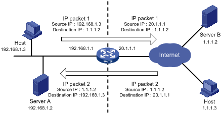
1. The internal host with an IP address of 192.168.1.3 sends an IP packet to the external server with an IP address of 1.1.1.2 through the NAT device.
2. Upon receiving the packet, the NAT device checks the IP header and finds that it is destined to the external network. Then it translates the private address 192.168.1.3 to the globally unique public address 20.1.1.1 and then forwards the packet to the server on the external network. Meanwhile, the NAT device adds the mapping of the two addresses into its NAT table.
3. The external server responds to the internal host with an IP packet whose destination IP address is 20.1.1.1. Upon receiving the packet, the NAT device checks the IP header, looks into its NAT table for the mapping, replaces the destination address with the private address of 192.168.1.3, and then sends the new packet to the internal host.
The above NAT operation is transparent to the terminals involved. The external server believes that the IP address of the internal host is 20.1.1.1 and is unaware of the private address 192.168.1.3. As such, NAT hides the private network from the external networks.
Despite the advantages of allowing internal hosts to access external resources and providing privacy, NAT also has the following disadvantages:
· As NAT involves translation of IP addresses, the IP headers cannot be encrypted. This is also true to the application protocol packets when the contained IP address or port number needs to be translated. For example, you cannot encrypt an FTP connection, or its port command cannot work correctly.
· Network debugging becomes more difficult. For example, when a host in a private network tries to attack other networks, it is harder to pinpoint the attacking host as the host IP address has been hidden.
NAT control
An enterprise needs to allow some hosts in the internal network to access external networks but prohibit others. This can be achieved through the NAT control mechanism. If a source IP address is among addresses denied, the NAT device does not translate the address. In addition, the NAT device only translates private addresses to specified public addresses.
NAT control can be achieved through an access control list (ACL) and an address pool.
· Only packets matching the ACL rules are served by NAT.
An address pool is a collection of consecutive public IP addresses for address translation. You can specify an address pool based on the number of available public IP addresses, the number of internal hosts, and network requirements. The NAT device selects an address from the address pool as the public address of an IP packet.
NAT operation
Basic NAT
As shown in Figure 1, when an internal network host accesses an external network, NAT uses a public IP address to replace the original internal IP address. In Figure 1, NAT uses the IP address of the outgoing interface as the public IP address. Thus all internal hosts use the same public IP address to access external networks and only one host is allowed to access external networks at a given time.
A NAT device can also hold multiple public IP addresses to support concurrent access requests. Whenever a new external network access request comes from the internal network, the NAT device chooses an available public IP address (if any) to replace the source IP address, adds the mapping to its NAT table, and forwards the packet. In this way, multiple internal hosts can access external networks simultaneously.
|
|
NOTE: The number of public IP addresses that a NAT device needs is usually far less than the number of internal hosts because not all internal hosts access external networks at the same time. The number of public IP addresses is related to the number of internal hosts that might access external networks simultaneously during peak hours. |
NAPT
Network Address Port Translation (NAPT) is a variation of basic NAT. It allows multiple internal addresses to be mapped to the same public IP address, which is called multiple-to-one NAT or address multiplexing.
NAPT mapping is based on both the IP address and the port number. With NAPT, packets from multiple internal hosts are mapped to the same external IP address with different port numbers.
Figure 2 depicts NAPT operation.
Figure 2 Diagram for NAPT operation
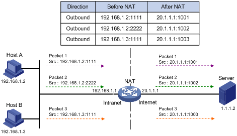
As shown in Figure 2, three IP packets arrive at the NAT gateway. Packets 1 and 2 are from the same internal address but have different source port numbers. Packets 1 and 3 are from different internal addresses but have the same source port number. NAPT maps the three IP packets to the same external address but with different source port numbers. Therefore, the packets can still be differentiated. When receiving the response packets, the NAT device forwards them to the corresponding hosts according to the destination addresses and port numbers.
NAPT can better utilize IP address resources, enabling more internal hosts to access the external network at the same time.
NAPT supports two NAT mapping behavior modes: Endpoint-Independent Mapping and Endpoint-Dependent Mapping.
· Endpoint-Independent Mapping
In this mode, the NAT device uses entries, each of which comprises the source IP address, source port number, and protocol type to translate addresses and filter packets. The same NAPT mapping applies to packets sent from the same internal IP address and port to any external IP address and port. The NAT device also allows external hosts to access the internal network by using the translated external addresses and port numbers. This mode facilitates communication among hosts that connect to different NAT devices.
· Address and Port-Dependent Mapping
In this mode, the NAT device uses entries each comprising the source IP address, source port number, protocol type, destination IP address, and destination port number to translate addresses and filter packets. For packets with the same source address and source port number but different destination addresses and destination port numbers, different NAPT mappings apply so that the source address and port number are mapped to the same external IP address but different port numbers. The NAT device allows the hosts only on the corresponding external networks where these destination addresses reside to access the internal network. This mode is secure but inconvenient for communication among hosts that connect to different NAT devices.
Internal server
NAT hides the internal network structure, including the identities of internal hosts. However, internal hosts such as a web server or an FTP server may need to be accessed by external hosts in practice. NAT satisfies this requirement by supporting internal servers.
You can configure an internal server on the NAT device by mapping a public IP address and port number to the private IP address and port number of the internal server. For instance, you can configure an address like 20.1.1.12:8080 as an internal web server’s external address and port number.
You can configure an internal server on the NAT device by mapping a public IP address and port number to the private IP address and port number of the internal server. For instance, you can configure an address like 20.1.1.12:8080 as an internal web server’s external address and port number.
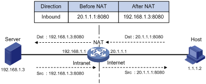
In Figure 3, when the NAT device receives a packet destined for the public IP address of an internal server, it looks in the NAT entries and translates the destination address and port number in the packet to the private IP address and port number of the internal server. When the NAT device receives a response packet from the internal server, it translates the source private IP address and port number of the packet into the public IP address and port number of the internal server.
Figure 3 Internal server operation
DNS mapping
Generally, the DNS server and users that need to access internal servers reside on the public network. You can specify an external IP address and port number for an internal server on the public network interface of a NAT device, so that external users can access the internal server using its domain name or pubic IP address. In Figure 4, an internal host wants to access an internal web server by using its domain name, while the DNS server is located on the public network. Typically, the DNS server replies with the public address of the internal server to the host and thus the host cannot access the internal server. The DNS mapping feature can solve the problem.
Figure 4 Operation of NAT DNS mapping
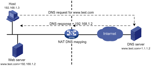
A DNS mapping entry records the domain name, public address, public port number, and protocol type of an internal server. Upon receiving a DNS reply, the NAT-enabled interface matches the domain name in the message against the DNS mapping entries. If a match is found, the private address of the internal server is found and the interface replaces the public IP address in the reply with the private IP address. Then, the host can use the private address to access the internal server.
Easy IP
Easy IP uses the public IP address of an interface on the router as the translated source address to save IP address resources, and uses ACLs to permit only certain internal IP addresses to be NATed.
Support for special protocols
Apart from the basic address translation function, NAT also provides an application layer gateway (ALG) mechanism that supports some special application protocols without requiring the NAT platform to be modified, featuring high scalability. The IP addresses or port numbers contained in such protocol messages may require address translation.
The special protocols that NAT supports include: File Transfer Protocol (FTP), Point-to-Point Tunneling Protocol (PPTP), Internet Control Message Protocol (ICMP), Domain Name System (DNS), Internet Locator Service (ILS), Real-Time Streaming Protocol (RTSP), H.323, Session Initiation Protocol (SIP), Netmeeting 3.01, and NetBIOS over TCP/IP (NBT).
NAT multiple-instance
This feature allows users from different MPLS VPNs to access external networks through the same outbound interface. It also allows them to have the same internal address. The process works as follows:
When an MPLS VPN user communicates with an external network, NAT replaces the internal IP address and port number with the NAT gateway’s external IP address and port number. It also records the relevant MPLS VPN information, such as the protocol type and router distinguisher (RD for short). When the response packet arrives, the NAT gateway then restores the external IP address and port number to the internal IP address and port number. Additionally, the NAT gateway can identify the MPLS VPN users who access the external network. Besides NAT, NAPT also supports multiple-instance.
The multiple-instance feature can also apply to internal servers so that external users can access an internal host of an MPLS VPN. For example, in MPLS VPN 1, the host that provides Web service has an internal address 10.110.1.1. The host can use 202.110.10.20 as an external IP address so that the Internet users can access the Web service in MPLS VPN 1 through this external address.
Moreover, NAT allows hosts in multiple MPLS VPNs to access each other by using the MPLS VPN information carried in the external IP address.
NAT configuration task list
Complete the following tasks to configure NAT:
|
Task |
Remarks |
|
|
Either is required |
||
|
Required |
||
|
Optional |
||
|
Binding a NAT-enabled interface to the NAT service interface |
Required |
|
|
Optional |
||
|
Optional |
||
|
|
NOTE: · NAT is supported on a provider edge router (PE), but not on a provider (P) router. · If the NAT configuration (address translation or internal server configuration) on an interface is changed, save the configuration and reboot the router (or use the reset nat session command to manually clear the relevant NAT entries), to avoid problems. The following are the possible problems: After you delete the NAT-related configuration, address translation can still work for sessions already created; if you configure NAT when NAT is running, the same configuration may have different results because of different configuration orders. · Make sure all the IP address pools referenced by the interfaces do not overlap each other. · When you configure twice NAT for multiple instances of a card with silkscreen IM-NAT and IM-NAT-II of a PE, specify the VPN to which a NAT address pool belongs. For more information, see “Dynamic NAT configuration example IV.” |
Configuring address translation
Introduction to address translation
A NAT device can be configured with or dynamically generate mapping entries to translate between internal and external network addresses. Generally, address translation can be classified into two types, dynamic and static.
· Static NAT
The mapping relationships between external and internal network addresses are manually configured. Static NAT can meet fixed access requirements of a few users.
· Dynamic NAT
A dynamic NAT entry is generated dynamically. It is implemented by associating an ACL with an address pool (or the address of an interface in the case of Easy IP). This association defines what packets can use the addresses in the address pool (or the interface’s address) to access the external network. Dynamic NAT is applicable when a large number of internal users need to access external networks. An IP address is selected from the associated address pool to translate an outgoing packet. After the session terminates, the selected IP address is released.
Both static NAT and dynamic NAT support NAT multiple-instance as long as the VPN instance of an IP address is provided.
Configuring static NAT
You must configure static NAT in system view, and make it effective in interface view.
Static NAT supports two modes, one-to-one and net-to-net.
|
|
CAUTION: When you configure static NAT, do not use any address from the dynamic NAT address pool or use any interface address as the public IP address; otherwise, traffic conflicts may occur. |
Configuring one-to-one static NAT
One-to-one static NAT translates a private IP address into a public IP address.
To configure one-to-one static NAT:
|
Step |
Command |
|
1. Enter system view. |
system-view |
|
2. Enter NAT service interface view. |
interface nat interface-number |
|
3. Configure a one-to-one static NAT mapping. |
nat static local-ip [ vpn-instance local-name ] global-ip [ vpn-instance global-name ] [ destination ip-address { mask-length | mask } ] [ interface interface-type interface-number [ next-hop ip-address ] ] [ unidirectional ] |
|
4. Return to system view. |
quit |
|
5. Enter interface view. |
interface interface-type interface-number |
|
6. Enable static NAT on the interface. |
nat outbound static |
Configuring net-to-net static NAT
Net-to-net static NAT translates a private network into a public network.
To configure net-to-net static NAT (I):
|
Step |
Command |
|
1. Enter system view. |
system-view |
|
2. Enter NAT service interface view. |
interface nat interface-number |
|
3. Configure a net-to-net static NAT mapping. |
nat static net-to-net local-network [ vpn-instance local-name ] global-network [ vpn-instance global-name ] { mask-length | mask } [ destination ip-address { mask-length | mask } ] [ interface interface-type interface-number [ next-hop ip-address ] ] [ unidirectional ] |
|
4. Exit NAT service interface view. |
quit |
|
5. Enter interface view. |
interface interface-type interface-number |
|
6. Enable static NAT on the interface. |
nat outbound static |
Configuring dynamic NAT
Dynamic NAT is usually implemented by associating an ACL with an address pool (or the address of an interface) on an interface.
· To select the address of an interface as the translated address, use Easy IP.
· To select an address from an address pool as the translated address, use No-PAT or NAPT for dynamic address translation. No-PAT is used in many-to-many address translation but does not translate TCP/UDP port numbers. NAPT allows for many-to-one address translation by translating also TCP/UDP port numbers.
Typically, a NAT entry is configured on the outbound interface of the NAT device. If internal hosts need to access external networks through multiple outbound interfaces on the NAT device, you must configure NAT entries on each of the interfaces, which is complex to implement. To avoid this, the router supports configuring a NAT entry on the inbound interface on the NAT device. When hosts in a VPN want to access other VPNs through multiple outbound interfaces on a NAT device, you can configure a NAT entry on the inbound interface on the NAT device, simplifying NAT configuration.
When a packet from an internal host to the external network arrives:
· If it is the first packet and an address pool is associated with an outbound interface, NAT determines whether to translate the packet based on the ACL (or packet source address). If yes, NAT chooses an address from the associated address pool or gets the associated interface address, performs address translation, and then saves the address mapping in the address translation table. All subsequent packets from the internal host are serviced by NAT directly according to the mapping entry.
· If an address pool is associated with an inbound interface, NAT determines whether to translate the packet based on the ACL. If yes, NAT redirects the packet to the NAT service card and performs address translation as in the above-mentioned process. You need to configure a QoS policy to redirect packets to an IM-NAT or IM-NAT-II card. For more information, see ACL and QoS Configuration Guide. This case does not support Easy IP.
|
|
NOTE: · The association of an address pool to an inbound interface set with the nat inbound command is effective only when an IM-NAT or IM-NAT-II card is present. · If both the inbound and outbound interfaces of a NAT device are associated with an address pool, a packet matching both of them uses an address from the address pool associated with the outbound interface for address translation. · You need to configure a QoS policy to redirect packets to an IM-NAT or IM-NAT-II card. For more information, see ACL and QoS Configuration Guide. Traffic classification commands supported in a QoS policy that is used for redirecting packets to a NAT board include: acl, customer-vlan-id, destination-mac, dscp ip-precedence, protocol, service-dot1p, service-vlan-id, and source-mac. |
Configuration prerequisites
· Configure an ACL to specify IP addresses permitted to be translated.
· Decide whether to use an interface’s IP address as the translated source address.
· Determine a public IP address pool for address translation.
· Decide whether to translate port information.
|
|
NOTE: For more information about ACL, see ACL and QoS Configuration Guide. |
Configuring NAT address pools
You can configure a NAT address pool, where the NAT device selects an IP address as the source address of a packet.
To configure an address pool:
|
Step |
Command |
Remarks |
|
1. Enter system view. |
system-view |
N/A |
|
Configure an address pool. |
nat address-group group-number start-address end-address |
Not necessary when the router provides only Easy IP, where an interface’s public IP address is used as the translated IP address. |
|
|
NOTE: The NAT address pool cannot contain addresses on the subnet where the interface resides, and a broadcast address. |
Configuring Easy IP
Easy IP allows the router to use the IP address of one of its interfaces as the source address of NATed packets.
To configure Easy IP:
|
Step |
Command |
|
1. Enter system view. |
system-view |
|
2. Enter interface view. |
interface interface-type interface-number |
|
3. Enable Easy IP by associating an ACL with the IP address of the interface. |
nat outbound acl-number [ next-hop ip-address ] |
Configuring No-PAT
With a specific ACL associated with an address pool or interface address, No-PAT translates the source address of a packet permitted by the ACL into an IP address of the address pool or the interface address, without using the port information.
To configure No-PAT:
|
Step |
Command |
Remarks |
|
1. Enter system view. |
system-view |
N/A |
|
2. Enter interface view. |
interface interface-type interface-number |
N/A |
|
3. Configure No-PAT. |
·
Configure No-PAT by associating an ACL with an
IP address pool on the outbound interface for translating only IP addresses: ·
Configure No-PAT by associating an ACL with an
IP address pool on the inbound interface for translating only IP addresses: |
Either command is required. |
Configuring NAPT
With a specific ACL associated with an address pool or interface address, NAPT translates the source address of a packet permitted by the ACL into an IP address of the address pool or the interface address, with using the port information.
To configure NAPT:
|
Step |
Command |
Remarks |
|
1. Enter system view. |
system-view |
N/A |
|
2. Enter interface view. |
interface interface-type interface-number |
N/A |
|
3. Configure NAPT. |
·
Configure NAPT by associating an ACL with an
IP address pool on the outbound interface for translating both IP address and
port number: ·
Configure NAPT by associating an ACL with an
IP address pool on the inbound interface for translating both IP address and
port number: |
Use at least one of the commands. |
Configuring an internal server
Introduction to internal server
To configure an internal server, you need to map an external IP address and port number to the internal server. This is done through executing the nat server command on an interface.
Internal server configurations include external network information (external IP address global-address and external port number global-port), internal network information (internal IP address local-address and internal port number local-port), and internal server protocol type. According to different internal/external network information configurations, internal servers can be classified into common internal servers and load shared internal servers.
Both internal servers and their external IP addresses can support MPLS VPN. If an internal server belongs to an MPLS VPN instance, you also need to specify the vpn-instance-name argument. Without this argument provided, the internal server does not belong to any VPN.
|
|
CAUTION: When you configure an internal server on an IM-NAT or IM-NAT-II card, the configuration takes effect on all Layer 3 interfaces bound to this NAT service interface. |
Configuring a common internal server
After mapping the internal IP address/port number (local-address and local-port) of a common internal server to an external IP address/port number (global-address and global-port), hosts in external networks can access the server located in the internal network.
To configure a common internal server:
|
Step |
Command |
Remarks |
|
1. Enter system view. |
system-view |
N/A |
|
2. Enter interface view. |
interface interface-type interface-number |
N/A |
|
3. Configure a common internal server. |
· nat server protocol pro-type global global-address [ global-port ] [ vpn-instance global-name ] inside local-address [ local-port ] [ vpn-instance local-name ] · nat server protocol pro-type global global-address global-port1 global-port2 [ vpn-instance global-name ] inside local-address1 local-address2 local-port [ vpn-instance local-name ] |
Use either command. |
Configuring load shared internal servers
|
|
NOTE: This feature is supported only when an IM-NAT or IM-NAT-II card is present. |
You can add an internal server (private network information) into an internal server group. If multiple members exist in the internal server group, they can provide the same service to hosts in external networks, thus to implement load sharing.
To configure load shared internal servers:
|
Step |
Command |
|
1. Enter system view. |
system-view |
|
2. Configure an internal server group. |
nat server-group group-number |
|
3. Add an internal server into the group. |
inside ip inside-ip port port-number |
|
4. Enter interface view. |
interface interface-type interface-number |
|
5. Configure load shared internal servers. |
nat server protocol pro-type global global-address global-port [ vpn-instance global-name ] inside server-group group-number [ vpn-instance local-name ] |
|
|
NOTE: · The internal server group referenced by the nat server command must have at least a member configured. · Each private IP address in an internal server group should be unique. |
Configuring DNS mapping
With DNS mapping, an internal host can access an internal server on the same private network by using the domain name of the internal server when the DNS server resides on the public network.
To configure a DNS mapping:
|
Step |
Command |
|
1. Enter system view. |
system-view |
|
2. Configure a DNS mapping. |
nat dns-map domain domain-name protocol pro-type ip global-ip port global-port |
Binding a NAT-enabled interface to the NAT service interface
Introduction
The IM-NAT card on the router is dedicated to process NAT services. You can bind a NAT-enabled interface with the NAT service interface on the card so that the NAT-enabled interface redirects all packets to the NAT service interface. This method improves NAT processing performance by using the hardware-based processing capability of the IM-NAT card.
Configuration procedure
To configure a NAT service interface binding:
|
Step |
Command |
Remarks |
|
1. Enter system view. |
system-view |
N/A |
|
2. Enter NAT service interface view. |
interface nat interface-number |
N/A |
|
3. Configure a NAT service interface binding. |
nat binding interface interface-type interface-number |
A NAT service interface can be bound with multiple NAT-capable interfaces. |
Configuring NAT logging
|
|
NOTE: · For the NAT log configuration, see Security Configuration Guide and the Network Management and Monitoring Configuration Guide. · A router installed with an IM-NAT or IM-NAT-II card does not output log information about static NAT and internal servers. |
Setting NAT connection limits
Connection limit overview
An internal user that initiates a large quantity of connections to external networks in a short period of time occupies large amounts of system resources of the device, making other users unable to access network resources normally. An internal server that receives large numbers of connection requests within a short time cannot process them in time or accept other normal connection requests. To avoid such situations, you can configure connection limit policies to collect statistics on and limit the number of connections, connection establishment rate, and connection bandwidth.
Creating a connection limit policy
A connection limit policy comprises a set of connection limit rules, which define the valid range and parameters for the policy.
To create a connection limit policy:
|
Step |
Command |
|
1. Enter system view. |
system-view |
|
2. Create a connection limit policy and enter its view. |
connection-limit policy policy-number |
Configuring the connection limit policy
A connection limit policy contains one or more source IP-based connection limit rules, each specifying an object or range for the limit. A user connection matching a rule will be limited based on the parameters in the rule.
A source IP-based connection limit rule limits connections initiated from a specified host or subnet that is on a VPN or the public network. It can limit the number of connections, connection establishment rate, or connection bandwidth.
A connection limit policy may comprise limit rules of different types. These rules are identified by IDs in different ranges. The limit rules are matched in ascending order of rule ID. When you configure connection limit rules for a policy, check the rules and their order carefully. H3C recommends you arrange the rules in ascending order of granularity and range.
A source IP-based connection limit rule can be any of these limit types:
· Host limit—Limits the connections of a specified host.
· Shared segment limit—Limits the connections of a specified network segment so that all the connections share the specified resources. This mode is identified by the shared keyword.
· Non-shared segment limit—Limits the connections of a specified network segment so that each connection on the segment enjoys the specified resources.
To configure a source IP-based connection limit rule:
|
Step |
Command |
|
1. Enter system view. |
system-view |
|
2. Enter connection limit policy view. |
connection-limit policy policy-number |
|
3. Configure a source IP-based connection limit rule. |
limit limit-id source { user-ip mask-length } [ vpn-instance vpn-instance-name ] { amount { dns max-amount | http max-amount | other max-amount | tcp max-amount } * | { bandwidth max-bandwidth | rate max- rate } } * [ shared ] |
Applying the connection limit policy
To make a connection limit policy take effect, apply it globally or to a service module.
To apply a connection limit policy:
|
Step |
Command |
Remarks |
|
1. Enter system view. |
system-view |
N/A |
|
2. Enter NAT interface view. |
interface nat interface-number |
N/A |
|
3. Apply a connection limit policy to the NAT interface. |
connection-limit apply policy policy-number |
Only one connection limit policy can be applied to a NAT interface. |
Enabling connection limit logging
After you enable the connection limit logging function, the connection limit operation information will be sent to the information center. The information mainly includes the source address, destination address, and protocol type of the connection, the maximum connections allowed, and a limit-reached message.
To enable connection limit logging:
|
Step |
Command |
Remarks |
|
1. Enter system view. |
system-view |
N/A |
|
2. Enter NAT service interface view. |
interface nat interface-number |
N/A |
|
3. Enable connection limit logging. |
connection-limit log enable |
Disabled by default. Available on an IM-NAT service card. |
|
|
NOTE: This command is available only on an interface of an IM-NAT or IM-NAT-II card. |
Displaying and maintaining NAT
|
Task |
Command |
Remarks |
|
Display information about NAT address pools. |
display nat address-group [ group-number ] [ | { begin | exclude | include } regular-expression ] |
Available in any view |
|
Display all NAT configuration information. |
display nat all [ | { begin | exclude | include } regular-expression ] |
Available in any view |
|
Display the NAT configuration information. |
display nat bound [ | { begin | exclude | include } regular-expression ] |
Available in any view |
|
Display the DNS mapping configuration information. |
display nat dns-map [ | { begin | exclude | include } regular-expression ] |
Available in any view |
|
Display the internal server information. |
display nat server [ | { begin | exclude | include } regular-expression ] |
Available in any view |
|
Display internal server group information. |
display nat server-group [ group-number ] [ | { begin | exclude | include } regular-expression ] |
Available in any view |
|
Display static NAT information. |
display nat static [ | { begin | exclude | include } regular-expression ] |
Available in any view |
|
Display NAT statistics. |
display interface nat-interface [ | { begin | exclude | include } regular-expression ] |
Available in any view |
|
Display information about the connection limit policy. |
display connection-limit policy { policy-number | all } [ | { begin | exclude | include } regular-expression ] |
Available in any view |
|
Display connection limit statistics. |
display connection-limit statistic [ ip user-ip ] [ vpn-instance vpn-instance-name ] interface interface-type interface-number [ | { begin | exclude | include } regular-expression ] |
Available in any view |
|
Display total connection limit statistics. |
display connection-limit statistics total interface interface-type interface-number [ | { begin | exclude | include } regular-expression ] |
Available in any view |
NAT configuration examples
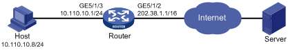
One-to-one static NAT configuration example
Network requirements
An internal host 10.110.10.8/24 uses public address 202.38.1.100 to access the Internet.
On the router, one of the following cards SPE-1010-II, SPE-1010-E-II, SPE-1020-II, SPE-1020-E-II, IM-NAT, and IM-NAT-II is installed in Slot 3.
An SPE card is installed in Slot 5.
Configuration procedure
# Configure the IP addresses for the interfaces as shown in Figure 5. (Details not shown)
# Configure a one-to-one static NAT mapping.
<Router> system-view
[Router] interface nat 3/0/2
[Router-NAT3/0/2] nat static 10.110.10.8 202.38.1.100
[Router-NAT3/0/2] quit
# Enable static NAT on interface GigabitEthernet 5/1/2.
[Router] interface GigabitEthernet 5/1/2
[Router-GigabitEthernet5/1/2] nat outbound static
[Router-GigabitEthernet5/1/2] quit
# Bind NAT service interface 3/0/2 to interface GigabitEthernet 5/1/2.
[Router] interface nat 3/0/2
[Router-NAT3/0/2] nat binding interface GigabitEthernet 5/1/2
[Router-NAT3/0/2] quit
Dynamic NAT configuration example I
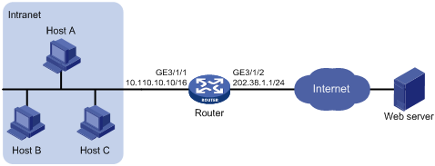
Network requirements
As shown in Figure 6, a company has three public IP addresses ranging from 202.38.1.1/24 to 202.38.1.3/24, and internal network address 10.110.0.0/16. Specifically, the company has the following requirements:
The internal users in subnet 10.110.10.0/24 can access the Internet by using public IP addresses 202.38.1.2 and 202.38.1.3, while users in other network segments cannot.
On the router, one of the following cards SPE-1010-II, SPE-1010-E-II, SPE-1020-II, SPE-1020-E-II, IM-NAT, and IM-NAT-II is installed in Slot 5.
An SPE card is installed in Slot 3.

Configuration procedure
# Configure the IP addresses for the interfaces as shown in Figure 6. (Details not shown)
# Configure address pool 1 containing 202.38.1.2 and 202.38.1.3.
<Router> system-view
[Router] nat address-group 1 202.38.1.2 202.38.1.3
# Configure ACL 2001, permitting only users from network segment 10.110.10.0/24 to access the Internet.
[Router] acl number 2001
[Router-acl-basic-2001] rule permit source 10.110.10.0 0.0.0.255
[Router-acl-basic-2001] rule deny
[Router-acl-basic-2001] quit
# Associate address pool 1 and ACL 2001 with the outbound interface GigabitEthernet 3/1/2.
[Router] interface GigabitEthernet 3/1/2
[Router-GigabitEthernet3/1/2] nat outbound 2001 address-group 1
[Router-GigabitEthernet3/1/2] quit
# Bind GigabitEthernet 3/1/2 to NAT service interface 5/0/1.
[Router] interface nat 5/0/1
[Router-NAT5/0/1] nat binding interface GigabitEthernet 3/1/2
[Router-NAT5/0/1] quit
Dynamic NAT configuration example II
Network requirements
As shown in Figure 7, a company has three public IP addresses ranging from 202.38.1.1/24 to 202.38.1.3/24, and internal network address 10.110.0.0/16. Specifically, the company has the following requirements:
· The internal users in subnet 10.110.10.0/24 can access the Internet using public IP addresses 202.38.1.2 and 202.38.1.3, while users in other network segments cannot.
· Configure the upper limit of connections (sourced from 10.110.10.100) as 1000, which means the number of connections initiated from the internal user to external servers cannot exceed 1000.

Configuration procedure
# Configure the IP addresses for the interfaces as shown in Figure 7. (Details not shown)
· Method I: Configure NAT on the outbound interface. (On the router, an IM-NAT or IM-NAT-II card is installed in Slot 5, and an SPE card is installed in Slot 3)
# Configure address pool 1 containing 202.38.1.2 and 202.38.1.3.
<Router> system-view
[Router] nat address-group 1 202.38.1.2 202.38.1.3
# Configure ACL 2001, permitting only users from network segment 10.110.10.0/24 to access the Internet.
[Router] acl number 2001
[Router-acl-basic-2001] rule permit source 10.110.10.0 0.0.0.255
[Router-acl-basic-2001] rule deny
[Router-acl-basic-2001] quit
# Associate address pool 1 and ACL 2001 with the outbound interface GigabitEthernet 3/1/2.
[Router] interface GigabitEthernet 3/1/2
[Router-GigabitEthernet3/1/2] nat outbound 2001 address-group 1
[Router-GigabitEthernet3/1/2] quit
# Bind GigabitEthernet 3/1/2 to NAT service interface 5/0/1.
[Router] interface nat 5/0/1
[Router-NAT5/0/1] nat binding interface GigabitEthernet 3/1/2
[Router-NAT5/0/1] quit
# Configure connection limit policy 1, limiting user connections sourced from 10.110.10.100. Set the upper limit of user connections to 1000.
[Router] connection-limit policy 1
[Router-connection-limit-policy-1] limit 0 source 10.110.10.100 32 amount other 1000
[Router-connection-limit-policy-1] quit
# Apply the connection limit policy to the NAT service interface 5/0/1.
[Router] interface nat 5/0/1
[Router-NAT5/0/1] connection-limit apply policy 1
[Router-NAT5/0/1] quit
· Method II: Configure NAT on the inbound interface. (On the router, an IM-NAT or IM-NAT-II card is installed in Slot 5, and an SPE card is installed in Slot 3.)
Figure 8 Network diagram
# Configure address pool 1.
<Router> system-view
[Router] nat address-group 1 202.38.1.2 202.38.1.3
# Configure ACL 2001, permitting only users from network segment 10.110.10.0/24 to access the Internet.
[Router] acl number 2001
[Router-acl-basic-2001] rule permit source 10.110.10.0 0.0.0.255
[Router-acl-basic-2001] rule deny
[Router-acl-basic-2001] quit
# Configure ACL 2002 for redirecting packets to the NAT board. Packets that are to be redirected to the NAT service interface requires address translation, so the ACL rules defined in ACL 2002 are the same as that in ACL 2001. You can also configure different ACL rules as needed.
[Router] acl number 2002
[Router-acl-basic-2002] rule permit source 10.110.10.0 0.0.0.255
[Router-acl-basic-2002] rule deny
[Router-acl-basic-2002] quit
# Configure a QoS policy to redirect packets to NAT 5/0/1.
[Router] traffic classifier 1
[Router-classifier-1] if-match acl 2002
[Router-classifier-1] quit
[Router] traffic behavior 1
[Router-behavior-1] redirect interface nat 5/0/1
[Router-behavior-1] quit
[Router] qos policy 1
[Router-qospolicy-1] classifier 1 behavior 1
[Router-qospolicy-1] quit
[Router] interface GigabitEthernet 3/1/1
[Router-GigabitEthernet3/1/1] qos apply policy 1 inbound
# Associate address pool 1 and ACL 2001 with the inbound interface GigabitEthernet 3/1/1.
[Router] interface GigabitEthernet 3/1/1
[Router-GigabitEthernet3/1/1] nat inbound 2001 address-group 1
# Bind the NAT service interface 5/0/1 with GigabitEthernet 3/1/1.
[Router] interface nat 5/0/1
[Router-NAT5/0/1] nat binding interface GigabitEthernet 3/1/1
# Configure connection limit policy 1, limiting user connections sourced from 10.110.10.100. Set the upper limit of user connections to 1000.
[Router] connection-limit policy 1
[Router-connection-limit-policy-1] limit 0 source 10.110.10.100 32 amount other 1000
[Router-connection-limit-policy-1] quit
# Apply connection limit policy 1 to the NAT service interface 5/0/1.
[Router] interface nat 5/0/1
[Router-NAT5/0/1] connection-limit apply policy 1
[Router-NAT5/0/1] quit
Dynamic NAT configuration example III
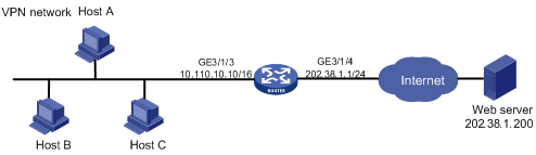
Network requirements
As shown in Figure 9, a company has three valid public IP addresses ranging from 202.38.1.1/24 to 202.38.1.3/24, and an internal network address of 10.110.0.0/16. The internal network belongs to VPN 1. NAT allows VPN 1 users to access the Internet.
On the router, an IM-NAT or IM-NAT-II card is installed in Slot 5, and an SPE card is installed in Slot 3.
Configuration procedure
# Configure the IP addresses for the interfaces as shown in Figure 9. (Details not shown)
# Configure VPN 1.
<Router> system-view
System View: return to User View with Ctrl+Z.
[Router] ip vpn-instance vpn1
[Router-vpn-instance-vpn1] route-distinguisher 1:1
[Router-vpn-instance-vpn1] quit
# Configure a default route with outbound interface GigabitEthernet 3/1/4 and next hop 202.38.1.250.
[Router] ip route-static vpn-instance vpn1 0.0.0.0 0 GigabitEthernet 3/1/4 202.38.1.250
# Associate GigabitEthernet 3/1/3 with VPN 1 and assign an IP address to GigabitEthernet 3/1/4.
[Router-GigabitEthernet3/1/3] ip binding vpn-instance vpn1
[Router-GigabitEthernet3/1/3] ip address 10.110.10.10 16
[Router-GigabitEthernet3/1/3] quit
[Router] interface GigabitEthernet 3/1/4
[Router-GigabitEthernet3/1/4] ip address 202.38.1.1 24
[Router-GigabitEthernet3/1/4] quit
# Configure NAT address pool 0.
[Router] nat address-group 0 202.38.1.2 202.38.1.3
# Configure ACL 2000.
[Router] acl num 2000
[Router-acl-basic-2000] rule permit vpn-instance vpn1
[Router-acl-basic-2000] rule deny
[Router-acl-basic-2000] quit
# Associate ACL 2000 with address pool 0 on the outbound interface.
[Router] interface GigabitEthernet 3/1/4
[Router-GigabitEthernet3/1/4] nat outbound 2000 address-group 0
[Router-GigabitEthernet3/1/4] quit
# Bind the NAT service interface 5/0/1 with GigabitEthernet 3/1/4.
[Router] interface nat 5/0/1
[Router-NAT5/0/1] nat binding interface gigabitethernet 3/1/4
[Router-NAT5/0/1] quit
Dynamic NAT configuration example IV
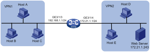
Network requirements
A company has two departments, A and B. Department A resides on network 192.168.1.0/24 and belongs to VPN 1. Department B resides on network 172.21.1.0/24 and belongs to VPN 2. The address pool contains IP addresses 202.38.1.2 and 202.38.1.3 and belongs to VPN 3. A web server resides on the same network as department B.
Configure the routers to allow access from department A to the web server.
On the router, an IM-NAT or IM-NAT-II card is installed in Slot 5, and an SPE card is installed in Slot 3.
Configuration procedure
|
|
NOTE: · When you configure twice NAT for multiple instances of a PE, specify the VPN to which the NAT address pool belongs. · When you configure twice NAT on a PE, do not specify the outbound interface. That is, do not specify the interface keyword in the nat static net-to-net, nat static, and nat inbound commands. |
# Configure the IP addresses for the interfaces as shown in Figure 10. (Details not shown)
# Configure VPNs.
<Router> system-view
[Router] ip vpn-instance vpn1
[Router-vpn-instance-vpn1] route-distinguisher 1:1
[Router-vpn-instance-vpn1] vpn-target 3:3 import-extcommunity
[Router-vpn-instance-vpn1] quit
[Router] ip vpn-instance vpn2
[Router-vpn-instance-vpn2] route-distinguisher 2:2
[Router-vpn-instance-vpn2] vpn-target 3:3 import-extcommunity
[Router-vpn-instance-vpn2] quit
[Router] ip vpn-instance vpn3
[Router-vpn-instance-vpn3] route-distinguisher 3:3
[Router-vpn-instance-vpn3] vpn-target 3:3 export-extcommunity
[Router-vpn-instance-vpn3] quit
# Enable route redistribution from NAT.
[Router] bgp 1
[Router-bgp] ipv4-family vpn-instance vpn3
[Router-bgp-vpn3] import-route static
[Router-bgp-vpn3] quit
[Router-bgp] quit
# Associate GigabitEthernet 3/1/3 with VPN 1 and GigabitEthernet 3/1/4 with VPN 2.
[Router] interface GigabitEthernet3/1/3
[Router-GigabitEthernet3/1/3] ip binding vpn-instance vpn1
[Router-GigabitEthernet3/1/3] ip address 192.168.1.1 24
[Router-GigabitEthernet3/1/3] quit
[Router] interface GigabitEthernet 3/1/4
[Router-GigabitEthernet3/1/4] ip binding vpn-instance vpn2
[Router-GigabitEthernet3/1/4] ip address 172.21.1.1 24
[Router-GigabitEthernet3/1/4] quit
# Configure ACL 3005.
[Router] acl number 3005
[Router-acl-adv-3005] rule permit ip vpn-instance vpn1 source any destination 202.38.1.3 0
[Router-acl-adv-3005] quit
# Configure NAT address pool 0.
[Router] nat address-group 0 202.38.1.2 202.38.1.3
# Associate ACL 3005 with address pool 0 on the inbound interface, and create a NAT server.
[Router] interface GigabitEthernet 3/1/3
[Router-GigabitEthernet3/1/3] nat inbound 3005 address-group 0 vpn-instance vpn3
[Router-GigabitEthernet3/1/3] nat server protocol tcp global 202.38.1.3 www vpn-instance vpn3 inside 172.21.1.243 www vpn-instance vpn2
[Router-GigabitEthernet3/1/3] quit
# Bind the NAT service interface 5/0/1 with GigabitEthernet 3/1/3.
[Router] interface nat 5/0/1
[Router-NAT5/0/1] nat binding interface gigabitethernet 3/1/3
[Router-NAT5/0/1] quit
Common internal server configuration example
Network requirements
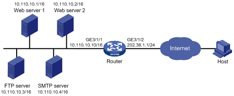
As shown in Figure 11, a company provides two web servers, one FTP server, and one SMTP server for external users to access. The internal network address is 10.110.0.0/16. The internal address for the FTP server is 10.110.10.3/16, for web server 1 is 10.110.10.1/16, for web server 2 is 10.110.10.2, and for the SMTP server 10.110.10.4/16. The company has three public IP addresses ranging from 202.38.1.1/24 to 202.38.1.3/24. Specifically, the company has the following requirements:
· External hosts can access internal servers with public address 202.38.1.1/24.
· Port 8080 is used for web server 2.
On the router, an IM-NAT or IM-NAT-II card is installed in Slot 5, and an SPE card is installed in Slot 3.
Configuration procedure
# Configure the IP addresses for the interfaces as shown in Figure 11. (Details not shown)
# Enter interface GigabitEthernet 3/1/2 view.
<Router> system-view
[Router] interface GigabitEthernet 3/1/2
# Configure the internal FTP server.
[Router-GigabitEthernet3/1/2] nat server protocol tcp global 202.38.1.1 ftp inside 10.110.10.3 ftp
# Configure the internal web server 1.
[Router-GigabitEthernet3/1/2] nat server protocol tcp global 202.38.1.1 www inside 10.110.10.1 www
# Configure the internal web server 2.
[Router-GigabitEthernet3/1/2] nat server protocol tcp global 202.38.1.1 8080 inside 10.110.10.2 www
# Configure the internal SMTP server.
[Router-GigabitEthernet3/1/2] nat server protocol tcp global 202.38.1.1 smtp inside 10.110.10.4 smtp
[Router-GigabitEthernet3/1/2] quit
# Bind the NAT service interface 5/0/1 with GigabitEthernet 3/1/2.
[Router] interface nat 5/0/1
[Router-NAT5/0/1] nat binding interface GigabitEthernet 3/1/2
[Router-NAT5/0/1] quit
Load sharing internal server configuration example
Network requirements
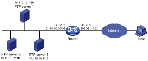
As shown in Figure 12, a company provides FTP services for external users. The public network address is 202.38.1.1/16. Three FTP servers are deployed to implement load sharing.
On the router, an IM-NAT or IM-NAT-II card is installed in Slot 5, and an SPE card is installed in Slot 3.
Configuration procedure
# Configure the IP addresses for the interfaces as shown in Figure 12. (Details not shown)
# Add members to internal server group 0.
<Router> system-view
[Router] nat server-group 0
[Router-nat-server-group-0] inside ip 10.110.10.1 port 21
[Router-nat-server-group-0] inside ip 10.110.10.2 port 21
[Router-nat-server-group-0] inside ip 10.110.10.3 port 21
[Router-nat-server-group-0] quit
# Associate internal server group 0 with GigabitEthernet 3/1/2 so that hosts in the server group can provide FTP services.
[Router] interface GigabitEthernet 3/1/2
[Router-GigabitEthernet3/1/2] nat server protocol tcp global 202.38.1.1 ftp inside server-group 0
[Router-GigabitEthernet3/1/2] quit
# Bind the NAT service interface 5/0/1 with GigabitEthernet 3/1/2.
[Router] interface nat 5/0/1
[Router-NAT5/0/1] nat binding interface GigabitEthernet 3/1/2
[Router-NAT5/0/1] quit
NAT DNS mapping configuration example
Network requirements
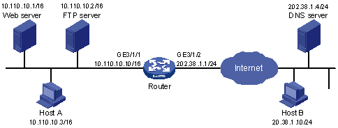
As shown in Figure 13, a company provides Web and FTP services to external users, and has its internal IP addresses on the network segment 10.110.0.0/16. The IP addresses of the Web and FTP servers are 10.110.10.1/16 and 10.110.10.2/16 respectively. The company has three public addresses 202.38.1.1/24 through 202.38.1.3/24. The DNS server is at 202.38.1.4/24.
· The public IP address 202.38.1.2 is used to provide services to external users.
· External users can use the public address or domain name of internal servers to access them.
· Internal users can access the internal servers by using their domain names.
Configuration procedure
# Configure the IP addresses for the interfaces as shown in Figure 13. (Details not shown)
# Enter the view of interface GigabitEthernet 3/1/2.
<Router> system-view
[Router] interface GigabitEthernet 3/1/2
# Configure the internal web server.
[Router-GigabitEthernet3/1/2] nat server protocol tcp global 202.38.1.2 inside 10.110.10.1 www
# Configure the internal FTP server.
[Router-GigabitEthernet3/1/2] nat server protocol tcp global 202.38.1.2 inside 10.110.10.2 ftp
[Router-GigabitEthernet3/1/2] quit
# Configure two DNS mapping entries: map the domain name www.server.com of the web server to 202.38.1.2, and ftp.server.com of the FTP server to 202.38.1.2.
[Router] nat dns-map domain www.server.com protocol tcp ip 202.38.1.2 port www
[Router] nat dns-map domain ftp.server.com protocol tcp ip 202.38.1.2 port ftp
[Router] quit
Verifying the configuration
# After completing the above configurations, display the DNS mapping configuration information.
<Router> display nat dns-map
NAT DNS mapping information:
There are currently 2 NAT DNS mapping(s)
Domain-name: www.server.com
Global-IP : 202.38.1.2
Global-port: 80(www)
Protocol : 6(TCP)
Domain-name: ftp.server.com
Global-IP : 202.38.1.2
Global-port: 21(ftp)
Protocol : 6(TCP)
Host A and Host B can use the domain name www.server.com to access the web server, and use ftp.server.com to access the FTP server.
Troubleshooting NAT
Symptom: internal server functions abnormally
Solution: Check whether the internal server host is properly configured; whether the router is correctly configured with respect to the internal server parameters, such as the internal server IP address. It is also possible that the firewall that has denied external access to the internal network. You can use the display acl command to verify this. For more information about firewall, see Security Configuration Guide.