- Table of Contents
-
- 05-Layer 3 - IP Services Configuration Guide
- 00-Preface
- 01-ARP Configuration
- 02-IP Addressing Configuration
- 03-DHCP Configuration
- 04-DNS Configuration
- 05-NAT Configuration
- 06-IP Performance Optimization Configuration
- 07-Adjacency Table Configuration
- 08-UDP Helper Configuration
- 09-IPv6 Basics Configuration
- 10-DHCPv6 Configuration
- 11-IPv6 DNS Configuration
- 12-NAT-PT Configuration
- 13-Tunneling Configuration
- 14-GRE Configuration
- Related Documents
-
| Title | Size | Download |
|---|---|---|
| 02-IP Addressing Configuration | 141.43 KB |
Contents
Assigning an IP address to an interface
Displaying and maintaining IP addressing
IP addressing configuration example
IP unnumbered configuration example
IP addressing overview
IP address classes
IP addressing uses a 32-bit address to identify each host on a network. To make addresses easier to read, they are written in dotted decimal notation, each being four octets in length. For example, address 00001000000000010000000100000001 in binary is written as 10.1.1.1.
Each IP address breaks down into two parts:
· Net ID—Identifies a network. The first several bits of a net ID, known as the class field or class bits, identify the class of the IP address.
· Host ID—Identifies a host on a network.
IP addresses are divided into five classes, as shown in Figure 1. The shaded areas represent the address class. The first three classes are widely used.
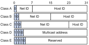
Table 1 describes the address ranges of these five classes.
Table 1 IP address classes and ranges
|
Class |
Address range |
Description |
|
A |
0.0.0.0 to 127.255.255.255 |
The IP address 0.0.0.0 is used by a host at bootstrap for temporary communication. This address is never a valid destination address. Addresses starting with 127 are reserved for loopback test. Packets destined to these addresses are processed locally as input packets rather than sent to the link. |
|
B |
128.0.0.0 to 191.255.255.255 |
N/A |
|
C |
192.0.0.0 to 223.255.255.255 |
N/A |
|
D |
224.0.0.0 to 239.255.255.255 |
Multicast address. |
|
E |
240.0.0.0 to 255.255.255.255 |
Reserved for future use except for the broadcast address 255.255.255.255. |
Special IP addresses
The following IP addresses are for special use, and they cannot be used as host IP addresses:
· IP address with an all-zero net ID—Identifies a host on the local network. For example, IP address 0.0.0.16 indicates the host with a host ID of 16 on the local network.
· IP address with an all-zero host ID—Identifies a network.
· IP address with an all-one host ID—Identifies a directed broadcast address. For example, a packet with the destination address of 192.168.1.255 will be broadcasted to all the hosts on the network 192.168.1.0.
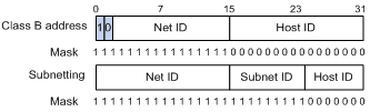
Subnetting and masking
Subnetting divides a network down into smaller networks called subnets by using some bits of the host ID to create a subnet ID.
Masking identifies the boundary between the host ID and the combination of net ID and subnet ID.
Each subnet mask comprises 32 bits that correspond to the bits in an IP address. In a subnet mask, consecutive ones represent the net ID and subnet ID, and consecutive zeros represent the host ID.
Before being subnetted, Class A, B, and C networks use these default masks (also called natural masks): 255.0.0.0, 255.255.0.0, and 255.255.255.0 respectively.
Figure 2 Subnetting a Class B network
Subnetting increases the number of addresses that cannot be assigned to hosts. Therefore, using subnets means accommodating somewhat fewer hosts.
For example, a Class B network without subnetting can accommodate 1022 more hosts than the same network subnetted into 512 subnets.
· Without subnetting, 65,534 hosts (216 – 2). (The two deducted addresses are the broadcast address, which has an all-one host ID, and the network address, which has an all-zero host ID.)
· With subnetting, using the first 9 bits of the host-id for subnetting provides 512 (29) subnets. However, only 7 bits remain available for the host ID. This allows 126 (27 – 2) hosts in each subnet, a total of 64,512 hosts (512 × 126).
Configuring IP addresses
An interface must has an IP address to communicate with other hosts. You can either manually assign an IP address to an interface, or configure the interface to obtain an IP address through BOOTP, DHCP, or PPP address negotiation. If you change the way an interface obtains an IP address, the new IP address will overwrite the previous one.
|
|
NOTE: · This router does not support IP address assignment through DHCP and BOOTP. · This chapter only covers how to assign an IP address manually. · For how to obtain an IP address through PPP address negotiation, see Layer 2—WAN Configuration Guide. |
Assigning an IP address to an interface
You may assign an interface multiple IP addresses, one primary and multiple secondaries.
Generally, you only need to assign the primary address to an interface. In some cases, you need to assign secondary IP addresses for the interface. For example, if the interface connects to two subnets, to enable the router to communicate with all hosts on the LAN, you need to assign a primary IP address and a secondary IP address to the interface.
To assign an IP address to an interface:
|
Step |
Command |
Remarks |
|
1. Enter system view. |
system-view |
N/A |
|
2. Enter interface view. |
interface interface-type interface-number |
N/A |
|
3. Assign an IP address to the interface. |
ip address ip-address { mask-length | mask } [ sub ] |
No IP address is assigned by default. You can assign only one primary, and up to 127 secondary IP addresses to an interface. |
|
|
CAUTION: · The primary IP address you assigned to the interface can overwrite the old one if there is any. · You cannot assign secondary IP addresses to an interface that obtains an IP address through PPP address negotiation or IP unnumbered. · The primary and secondary IP addresses you assign to the interface can be located on the same network segment, but different interfaces on your device must reside on different network segments. |
Displaying and maintaining IP addressing
|
Task |
Command |
Remarks |
|
Display IP configuration information for a specified Layer 3 interface or all Layer 3 interfaces. |
display ip interface [ interface-type interface-number ] [ | { begin | exclude | include } regular-expression ] |
Available in any view |
|
Display brief IP configuration information for a specified Layer 3 interface or all Layer 3 interfaces. |
display ip interface [ interface-type [ interface-number ] ] brief [ | { begin | exclude | include } regular-expression ] |
Available in any view |
IP addressing configuration example
Network requirements
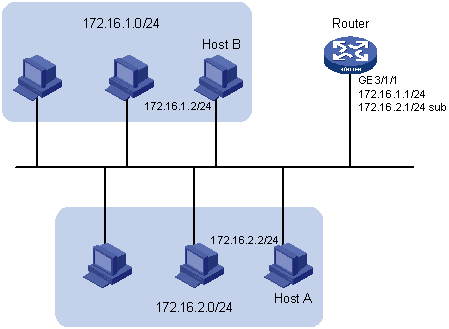
As shown in Figure 3, GigabitEthernet 3/1/1 on Router is connected to a LAN comprising two segments: 172.16.1.0/24 and 172.16.2.0/24.
To enable the hosts on the two network segments to access the external network through the router, and enable the hosts on the two network segments to communicate with each other, do the following:
· Assign a primary IP address and a secondary IP address to GigabitEthernet 3/1/1 on the router.
· Set the router as the gateway on all hosts.
Configuration procedure
# Assign a primary IP address and a secondary IP address to GigabitEthernet 3/1/1.
<Router> system-view
[Router] interface GigabitEthernet 3/1/1
[Router-GigabitEthernet3/1/1] ip address 172.16.1.1 255.255.255.0
[Router-GigabitEthernet3/1/1] ip address 172.16.2.1 255.255.255.0 sub
# Set the gateway address to 172.16.1.1 on the PCs attached to 172.16.1.0/24, and to 172.16.2.1 on the PCs attached to 172.16.2.0/24.
# Ping a host on subnet 172.16.1.0/24 from the router to check the connectivity.
<Router> ping 172.16.1.2
PING 172.16.1.2: 56 data bytes, press CTRL_C to break
Reply from 172.16.1.2: bytes=56 Sequence=1 ttl=255 time=25 ms
Reply from 172.16.1.2: bytes=56 Sequence=2 ttl=255 time=27 ms
Reply from 172.16.1.2: bytes=56 Sequence=3 ttl=255 time=26 ms
Reply from 172.16.1.2: bytes=56 Sequence=4 ttl=255 time=26 ms
Reply from 172.16.1.2: bytes=56 Sequence=5 ttl=255 time=26 ms
--- 172.16.1.2 ping statistics ---
5 packet(s) transmitted
5 packet(s) received
0.00% packet loss
round-trip min/avg/max = 25/26/27 ms
The output shows that the router can communicate with the host on subnet 172.16.1.0/24.
# Ping a host on subnet 172.16.2.0/24 from the router to check the connectivity.
<Router> ping 172.16.2.2
PING 172.16.2.2: 56 data bytes, press CTRL_C to break
Reply from 172.16.2.2: bytes=56 Sequence=1 ttl=255 time=25 ms
Reply from 172.16.2.2: bytes=56 Sequence=2 ttl=255 time=26 ms
Reply from 172.16.2.2: bytes=56 Sequence=3 ttl=255 time=26 ms
Reply from 172.16.2.2: bytes=56 Sequence=4 ttl=255 time=26 ms
Reply from 172.16.2.2: bytes=56 Sequence=5 ttl=255 time=26 ms
--- 172.16.2.2 ping statistics ---
5 packet(s) transmitted
5 packet(s) received
0.00% packet loss
round-trip min/avg/max = 25/25/26 ms
The output shows that the router can communicate with the host on subnet 172.16.2.0/24.
# Ping a host on subnet 172.16.1.0/24 from a host on subnet 172.16.2.0/24 to check the connectivity. Host B can be successfully pinged from Host A.
Configuring IP unnumbered
IP unnumbered overview
Logically, to enable IP on an interface, you must assign this interface a unique IP address. Yet, you can borrow an IP address already configured on one of other interfaces on your device instead. This is called IP unnumbered and the interface borrowing the IP address is called IP unnumbered interface.
You may use IP unnumbered to save IP addresses either when available IP addresses are inadequate or when an interface is brought up only for occasional use.
Configuration prerequisites
Assign a primary IP address to the interface from which you want to borrow the IP address. Alternatively, you may configure the interface to obtain one through PPP address negotiation.
Configuration procedure
To configure IP unnumbered on an interface:
|
Step |
Command |
Remarks |
|
1. Enter system view. |
system-view |
N/A |
|
2. Enter interface view. |
interface interface-type interface-number |
N/A |
|
3. Specify the current interface to borrow the IP address of the specified interface. |
ip address unnumbered interface interface-type interface-number |
The interface does not borrow IP addresses from other interfaces by default. |
|
|
CAUTION: · Serial, POS, and ATM interfaces can borrow IP addresses from Layer 3 Ethernet interfaces or other interfaces. · Layer 3 Ethernet interfaces and loopback interfaces cannot borrow IP addresses of other interfaces, but other interfaces can borrow IP addresses of these interfaces. · An interface cannot borrow an IP address from an unnumbered interface. · Multiple interfaces can use the same unnumbered IP address. · The IP address of the borrowing interface always keeps consistent and varies with that of the borrowed interface. If an IP address is configured for the borrowed interface, the IP address of the borrowing interface is the same as that of the borrowed interface; if no IP address is configured for the borrowed interface, no IP address is assigned for the borrowing interface. |
IP unnumbered configuration example
Network requirements
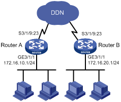
As shown in Figure 4, two routers on an intranet are connected to each other through serial interfaces across a Digital Data Network (DDN), and they each connect to a LAN through Ethernet interfaces.
To save IP addresses, configure the serial interfaces to borrow IP addresses from the Ethernet interfaces.
Configuration procedure
1. Configure Router A:
# Assign a primary IP address to GigabitEthernet 3/1/1.
<RouterA> system-view
[RouterA] interface GigabitEthernet 3/1/1
[RouterA-GigabitEthernet3/1/1] ip address 172.16.10.1 255.255.255.0
[RouterA-GigabitEthernet3/1/1] quit
# Configure Serial 3/1/9:23 to borrow an IP address from GigabitEthernet 3/1/1.
[RouterA] interface serial 3/1/9:23
[RouterA-Serial3/1/9:23] ip address unnumbered interface GigabitEthernet 3/1/1
[RouterA-Serial3/1/9:23] quit
# Create a route to the subnet attached to Router B, specifying interface Serial 3/1/9:23 as the outgoing interface.
[RouterA] ip route-static 172.16.20.0 255.255.255.0 serial 3/1/9:23
2. Configure Router B:
# Assign a primary IP address to GigabitEthernet 3/1/1.
<RouterB> system-view
[RouterB] interface GigabitEthernet 3/1/1
[RouterB-GigabitEthernet3/1/1] ip address 172.16.20.1 255.255.255.0
[RouterB-GigabitEthernet3/1/1] quit
# Configure interface Serial 3/1/9:23 to borrow an IP address from GigabitEthernet 3/1/1.
[RouterB] interface serial 3/1/9:23
[RouterB-Serial3/1/9:23] ip address unnumbered interface GigabitEthernet 3/1/1
[RouterB-Serial3/1/9:23] quit
# Create a route to the subnet attached to Router A, specifying interface Serial 3/1/9:23 as the outgoing interface.
[RouterB] ip route-static 172.16.10.0 255.255.255.0 serial 3/1/9:23
3. Ping a host attached to Router B from Router A to verify the configuration.
[RouterA] ping 172.16.20.2
PING 172.16.20.2: 56 data bytes, press CTRL_C to break
Reply from 172.16.20.2: bytes=56 Sequence=1 ttl=255 time=25 ms
Reply from 172.16.20.2: bytes=56 Sequence=2 ttl=255 time=25 ms
Reply from 172.16.20.2: bytes=56 Sequence=3 ttl=255 time=26 ms
Reply from 172.16.20.2: bytes=56 Sequence=4 ttl=255 time=26 ms
Reply from 172.16.20.2: bytes=56 Sequence=5 ttl=255 time=26 ms
--- 172.16.20.2 ping statistics ---
5 packet(s) transmitted
5 packet(s) received
0.00% packet loss
round-trip min/avg/max = 25/25/26 ms
The output shows that the host can be pinged.