- Table of Contents
- Related Documents
-
| Title | Size | Download |
|---|---|---|
| 02-Spanning Tree Troubleshooting Guide | 125.35 KB |
Troubleshooting Layer 2—LAN switching
Spanning tree issues
Service interruption caused by a loop
Symptom
Services are interrupted when multiple devices are connected into a loop through physical links.
Common causes
The following are the common causes of this type of issue:
· The physical state of the device interfaces is down.
· The spanning tree feature is disabled on the device.
Troubleshooting flow
Figure 1 shows the troubleshooting flowchart.
Figure 1 Flowchart for troubleshooting service interruption caused by a loop

Solution
1. Check if the state of the interfaces forwarding service traffic is up.
a. Check if the physical state of the interfaces is up.
Execute the display interface brief command to check if the physical state of the network interfaces is up by examining the Link field.
<Sysname> display interface brief
Brief information on interfaces in route mode:
Link: ADM - administratively down; Stby - standby
Protocol: (s) - spoofing
Interface Link Protocol Primary IP Description
InLoop0 UP UP(s) --
MGE0/0/0 DOWN DOWN --
NULL0 UP UP(s) --
REG0 UP -- --
Brief information on interfaces in bridge mode:
Link: ADM - administratively down; Stby - standby
Speed: (a) - auto
Duplex: (a)/A - auto; H - half; F - full
Type: A - access; T - trunk; H - hybrid
Interface Link Speed Duplex Type PVID Description
XGE0/0/6 ADM auto A A 1
- If the state of the interfaces is up, proceed to step b.
- If the state of an interface is ADM, execute the undo shutdown command in interface view to activate this interface. If the state of the interface remains down, check the interface link and related configurations. If the state of the interface is up and the issue persists, proceed to step b.
- If the state of an interface is down, troubleshoot the interface link and related configurations. If the state of the interface is up and the issue persists, proceed to step b.
b. Check if the state of the data link layer (DDL) protocol on the interface is up. The interface with a down DDL protocol cannot participate in computing the spanning tree topology.
Execute the display interface command and check whether the DDL protocol state of the interface is up by examining the Line protocol state field.
<Sysname> display interface gigabitethernet 1/0/2
Ten-GigabitEthernet0/0/7
Current state: UP
Line protocol state: DOWN(LAGG)
...
DOWN(protocols) indicates that the DDL of the interface is shut down by one or more protocol modules. The protocols argument can be any combination of the following protocols:
- DLDP—The DDL of the interface is shut down because the DLDP module detects a unidirectional communication.
- OAM—The DDL of the interface is shut down because the Ethernet OAM module detects a remote link fault.
- LAGG—The DDL of the interface is shut down because there are no selected member ports for the aggregate interface.
- BFD—The DDL of the interface is shut down because the BFD module detects a link fault.
- VBP—The DDL of the interface is shut down because Layer 2 forwarding is configured.
If the DDL of the interface is shut down by the above protocols, review and adjust the configuration of these modules to restore the DDL protocol state of the interface to up. If the issue persists, proceed to step 2.
2. Check if the spanning tree feature on the devices is enabled.
a. Check whether the global spanning tree feature is enabled on the devices.
Execute the display stp command.
- If the following output appears, the global spanning tree protocol is not enabled:
<Sysname> display stp
Protocol status : Disabled
Protocol Std. : IEEE 802.1s
Version : 3
Bridge-Prio. : 32768
MAC address : 2eae-3769-0200
Max age(s) : 20
Forward delay(s) : 15
Hello time(s) : 2
Max hops : 20
TC Snooping : Disabled
<Sysname> display stp
STP is not configured.
Execute the stp global enable command under system view to enable the global spanning tree feature.
- If the state and statistical information of the spanning tree appear as shown below, the global spanning tree feature is enabled. Proceed to step b.
<Sysname> display stp
-------[CIST Global Info][Mode MSTP]-------
Bridge ID : 32768.2eae-3769-0200
Bridge times : Hello 2s MaxAge 20s FwdDelay 15s MaxHops 20
Root ID/ERPC : 32768.2eae-3769-0200, 0
RegRoot ID/IRPC : 32768.2eae-3769-0200, 0
RootPort ID : 0.0
BPDU-Protection : Disabled
Bridge Config-
Digest-Snooping : Disabled
TC or TCN received : 0
Time since last TC : 0 days 2h:49m:11s
----[Port2(Ten-GigabitEthernet0/0/6)][DOWN]----
Port protocol : Enabled
Port role : Disabled Port
Port ID : 128.54
Port cost(Legacy) : Config=auto, Active=200000
Desg.bridge/port : 32768.2eae-3769-0200, 128.54
Port edged : Config=disabled, Active=disabled
Point-to-Point : Config=auto, Active=false
Transmit limit : 10 packets/hello-time
TC-Restriction : Disabled
Role-Restriction : Disabled
Protection type : Config=none, Active=none
MST BPDU format : Config=auto, Active=802.1s
Port Config-
Digest-Snooping : Disabled
Rapid transition : False
Num of VLANs mapped : 1
Port times : Hello 2s MaxAge 20s FwdDelay 15s MsgAge 0s RemHops 20
BPDU sent : 0
TCN: 0, Config: 0, RST: 0, MST: 0
BPDU received : 0
TCN: 0, Config: 0, RST: 0, MST: 0
b. Check whether the spanning tree feature is enabled for VLANs. (Only applicable when the spanning tree mode is PVST. Proceed to step c for any other spanning tree mode.)
Execute the display this command in system view to check whether the undo stp vlan enable command exists.
[Sysname] display this
...
#
undo stp vlan 2 enable
stp mode pvst
stp global enable
#
...
If the above configuration exists and the network requires enabling the spanning tree feature for the VLANs, execute the stp vlan enable command in system view to enable the spanning tree feature on the VLANs.
c. Check if the spanning tree feature is enabled on the interfaces.
Execute the display stp command to check if the spanning tree feature is not enabled on interfaces.
<Sysname> display stp
...
----[Port2(Ten-GigabitEthernet0/0/6)][DISABLED]----
Port protocol : Disabled
...
Execute the stp enable command in interface view to activate the spanning tree feature on the interfaces participating in the spanning tree calculations.
3. If the issue persists, collect the following information and contact Technical Support:
¡ Results of each step.
¡ The configuration file, log messages, and alarm messages.
Related alarm and log messages
Alarm messages
· N/A
Log messages
· N/A
User endpoint disconnection in the spanning tree network
Symptom
When a user endpoint is connected to the spanning tree network, transitent disconnection occurs on the interface connecting the endpoint, causing persistent packet loss and endpoint disconnection.
Common causes
The interface connected to the user endpoint device is not configured as an edge port.
Troubleshooting flow
Figure 2 shows the troubleshooting flowchart.
Figure 2 Flowchart for troubleshooting user endpoint disconnection in the spanning tree network
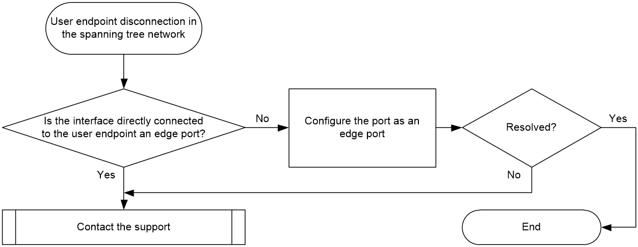
Solution
1. Check whether the interfaces directly connected to the user endpoint are edge ports in the spanning tree network.
Execute the display stp command on the device directly connected to the user endpoint to check if the interface directly connected to the user endpoint is an edge port.
<Sysname> display stp
...
----[Port2(Ten-GigabitEthernet0/0/6)][FORWARDING]----
Port protocol : Enabled
Port role : Designated Port
Port ID : 128.2
Port cost(Legacy) : Config=auto, Active=20
Desg.bridge/port : 32768.2eae-3769-0200, 128.2
Port edged : Config=enabled, Active=enabled
Point-to-Point : Config=auto, Active=true
Transmit limit : 10 packets/hello-time
Protection type : Config=none, Active=none
Rapid transition : True
Port times : Hello 2s MaxAge 20s FwdDelay 15s MsgAge 0s
...
¡ If yes, proceed to step 2.
¡ If not, execute the stp edged-port command in interface view to configure this port as an edge port.
|
|
IMPORTANT: The edge port and loop guard features cannot be configured simultaneously on an interface. If the device outputs the following error prompt when you execute the stp edged-port command, the interface has the loop guard feature configured. In this case, you must execute the undo stp loop-protection command to disable the loop guard feature before you execute the stp edged-port command. |
Failed to enable edged-port on Ten-GigabitEthernet0/0/6, because loop-protection is enabled.
2. If the issue persists, collect the following information and contact Technical Support:
¡ Results of each step.
¡ The configuration file, log messages, and alarm messages.
Related alarm and log messages
Alarm messages
· N/A
Log messages
Unchangeable master port in an MSTI other than MSTI 0
Symptom
In an MSTP network, for instances other than MSTI 0 on the device, ports that should not have the master role are calculated as master ports. The master port roles cannot be changed by adjusting parameters such as priority and cost values.
Common causes
In an MST region, devices have inconsistent MST region configurations.
Troubleshooting flow
If the MST region configurations of two devices are inconsistent, a device will consider that the peer device and the local device are not in the same MST region. A port connected to a device in the region will be calculated as the master port. To resolve this issue, check the MST region configuration of devices in the same MST region to ensure that the configurations of each device are consistent.
Figure 3 shows the troubleshooting flowchart.
Figure 3 Flowchart for troubleshooting unchangeable master port in an MSTI other than MSTI 0
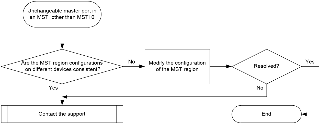
Solution
1. Make sure that devices in the same MST region have the same region name, revision level, and VLAN mapping table configuration for the MST region.
Execute the display stp region-configuration command to view the effective MST region configuration of the devices.
<Sysname> display stp region-configuration
Oper Configuration
Format selector : 0
Region name : hello
Revision level : 0
Configuration digest : 0x5f762d9a46311effb7a488a3267fca9f
Instance VLANs Mapped
0 21 to 4094
1 1 to 10
2 11 to 20
¡ Region name—The region name of the MST region. Execute the stp region-configuration command in system view to enter MST region view, and configure the region name with the region-name command.
¡ Revision level—Revision level of the MST region. Execute the stp region-configuration command in system view to enter MST region view, and configure the revision level with the revision-level command.
¡ Instance VLANs Mapped—VLAN mapping relationships of the MST region. Execute the stp region-configuration command in system view to enter MST region view, and configure VLAN mapping relationships with the instance or the vlan-mapping modulo command.
If the above parameters are inconsistent on different devices within the same MST region, change the parameter configurations to be consistent. After configuring the parameters of the MST region, execute the active region-configuration command in MST region view to activate the user configuration of the MST region. If not, the previous configuration will still take effect on the MST region.
2. If the issue persists, collect the following information and contact Technical Support:
¡ Results of each step.
¡ The configuration file, log messages, and alarm messages.
Related alarm and log messages
Alarm messages
· N/A
Log messages
· N/A
Spanning tree link flapping
Symptom
Frequent network topology changes caused by constant changes of the spanning tree root bridge, port role, and port state
Common causes
The following are the common causes of this type of issue:
· Link flapping: The properties of a certain port's link, such as the state, rate, and duplex mode, change frequently.
· Node fault: The CPU usage of the devices on the network is high and the spanning tree packets cannot be processed in a timely manner. A device reboots repeatedly, causing the spanning tree to be constantly recalculated.
· Network failures:
¡ Packet congestion leads to BPDU loss.
¡ A device received a BPDU from another network unexpectedly, triggering a recalculation of the current network's spanning tree.
¡ Other features of the device cause BPDUs to be discarded incorrectly.
Troubleshooting flow
Figure 4 shows the troubleshooting flowchart.
Figure 4 Flowchart for troubleshooting spanning tree link flapping
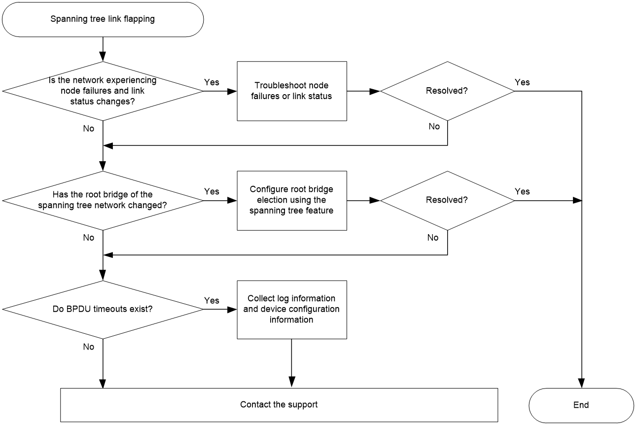
Solution
1. Check if any device in the spanning tree network is experiencing high CPU usage, rebooting, or changes in the status of the interface links.
Based on the network deployment, use the controller, device management platform, and user interface to check whether the devices are experiencing high CPU usage, rebooting, or changes in the status of the interface links.
If both the device state and link state have returned to stability, but the issue persists, proceed to step 2.
2. Check whether the root bridge of the spanning tree network is changed.
In the spanning tree network, execute the display stp root command to view the root bridge in the current spanning tree network.
<Sysname> display stp root
MST ID Root Bridge ID ExtPathCost IntPathCost Root Port
0 32768.14e3-19d3-0100 0 40 XGE0/0/7
10 0.14e3-19d3-0100 0 40 XGE0/0/7
20 0.14e3-1f59-0200 0 0
The Root Bridge ID field indicates the ID of the root bridge in the spanning tree network. The format of the root bridge ID is priority.bridge MAC address. Use this field to determine whether the root bridge in the spanning tree network is the desired device. If the root bridge device is correct but the spanning tree network still keeps flapping, proceed to step 3. If the root bridge device is not the desired one, you can modify the root bridge as follows:
¡ Change the priority of the desired device. The priority of a device participates in the spanning tree calculation. The smaller the value, the higher the priority. Execute the stp priority command to set the priority level of the desired device to 0 or a smaller value, so that the specified device becomes the spanning tree root bridge.
¡ Execute the stp root primary command on the desired device to configure this device as the root bridge of the spanning tree.
After you configure the desired device as the root bridge, maintain the stability of the root bridge and network topology with the following functions:
¡ Enable root guard.
After configuring the stp root-protection command in interface view, this interface can only act as a designated port in all MSTIs. When this interface receives a BPDU with higher priority level from an MSTI, it immediately transits to listening state, no longer forwarding packets (which is equivalent to disconnect this interface). If no superior BPDU is received within double the forward delay time (the default forward delay time is 15 seconds), the interface will restore to its normal state. The root guard function can avoid illegal changes in the spanning tree topology caused by misconfiguration or vicious attacks.
¡ Configure the edge port and BPDU guard.
For access layer devices, access ports are usually directly connected to user endpoints (such as PCs) or file servers. Access ports must be configured as edge ports for fast port migration. Under normal circumstances, an access port does not exchange STP BPDUs with user endpoints. If the access port receives BPDUs, network topology change and spanning tree network flapping might occur.
Spanning tree provides BPDU guard feature to solve this issue. Execute stp bpdu-protection command in system or interface view. When edge ports receive BPDUs, the system will shut down these ports and notify the user that these ports have been shut down by spanning tree. The shutdown ports will be reactivated after a time interval configured by using the shutdown-interval command.
¡ Enable loop guard.
A downstream device relies on continuous BPDUs sent by the upstream device to maintain the state of the root port and blocked ports. If a link congestion or unidirectional link fault occurs, these ports cannot receive BPDUs from the upstream device. In this case, the downstream device reselects the port role, causing the root port of the downstream device to convert to the designated port. The blocked ports transit to the forwarding state, and a loop occurs in the switched network.
Execute the stp loop-protection command on the root port and alternate port of downstream devices to configure the loop guard feature to suppress the occurrence of the above loops. On a port with the loop guard feature enabled, the initial state of all MSTIs is discarding. If the port receives BPDUs, these MSTIs can perform normal state transitions. If the port does not receive BPDUs, these MSTIs will remain in the discarding state to avoid loops.
Do not configure the loop guard feature on a port connected to a user endpoint. Otherwise, the port will remain discarding and cannot forward user traffic.
¡ Enable TC-BPDU guard.
If TC-BPDUs are used to attack a device, the device will receive a large number of TC-BPDUs within a short period of time. Then, the device is busy with forwarding entry flushing. This affects network stability. You can enable TC-BPDU guard to prevent frequent flushing of forwarding entries. Execute the stp tc-protection command in system view to enable the TC-BPDU guard feature. Execute the stp tc-protection threshold number command in system view to configure the maximum number of forwarding entry flushes that the device can perform every 10 seconds.
With the TC-BPDU guard feature enabled, if the number of times the device receives TC-BPDUs within 10 seconds is greater than the specified number, the device only refresh the forwarding entries the specified number of times during this period. For excess TC-BPDUs, the device refreshes the forwarding entries uniformly after this period of time.
If the issue persists, proceed to step 3.
3. Troubleshoot for BPDU timeout.
Check whether the device outputs the STP_BPDU_RECEIVE_EXPIRY log. This log describes that the device has not received any BPDUs within the BPDU timeout time, which has triggered spanning tree recalculation. The cause of BPDU timeout might be congestion in BPDU forwarding on the network, or other configurations on the device causing BPDUs to be incorrectly discarded.
To locate the fault more accurately, proceed to step 4.
4. If the issue persists, collect the following information and contact Technical Support:
¡ Results of each step.
¡ The configuration file, log messages, and alarm messages.
Related alarm and log messages
Log messages
· STP/5/STP_BPDU_RECEIVE_EXPIRY
· STP/6/STP_DETECTED_TC
· STP/6/STP_NOTIFIED_TC
Alarm messages
· N/A