- Table of Contents
- Related Documents
-
| Title | Size | Download |
|---|---|---|
| 04-Features | 1.25 MB |
Link layer authentication and key management
Wireless service configuration
Bandwidth guaranteeing features
Wireless configuration
Wireless services
WLAN access
WLAN access provides access to WLANs for wireless clients.
Wireless service
A wireless service defines a set of wireless service attributes, such as SSID and authentication method.
SSID
A service set identifier is the name of a WLAN.
Default VLAN
A client is assigned to the default VLAN after it accesses the WLAN.
SSID hiding
APs advertise SSIDs in beacon frames. If the number of clients in a BSS exceeds the limit or the BSS is unavailable, you can enable SSID-hidden to prevent clients from discovering the BSS. When SSID-hidden is enabled, the BSS hides its SSID in beacon frames and does not respond to broadcast probe requests. A client must send probe requests with the specified SSID to access the WLAN. This feature can protect the WLAN from being attacked.
SSID-based user isolation
SSID-based user isolation is applicable to both local forwarding mode and centralized forwarding mode.
When SSID-based user isolation is enabled for a service, the device isolates all wireless users that access the network through the service in the same VLAN.
Authentication mode
|
|
NOTE: For information about MAC authentication and portal authentication, see "Access authentication." |
Open system authentication
Open system authentication is the default authentication method and the simplest authentication algorithm, which means no authentication. If the authentication type is set to open system authentication, any clients can pass the authentication.
Enhanced open system authentication
Enhanced Open system authentication is an enhanced open authentication service that provides data encryption for wireless clients supporting the Opportunistic Wireless Encryption (OWE) protocol in open wireless access networks. With this service, clients that support the OWE protocol can connect to the network without entering a password. The device and client will automatically negotiate a key using the OWE protocol to encrypt data packets.
PSK authentication
PSK authentication requires the same PSK to be configured for both an AP and a client. PSK integrity is verified during the four-way handshake. If PSK negotiation succeeds, the client passes the authentication.
802.1X authentication
The authenticator uses EAP relay or EAP termination to communicate with the RADIUS server. The authenticator can be either the AC or AP.
· Online user handshake—The online user handshake feature examines the connectivity status of online 802.1X clients. The device periodically sends handshake messages to online clients. If the device does not receive any responses from an online client after it has made the maximum handshake attempts, the device sets the client to offline state.
· Online user handshake security—The online user handshake security feature adds authentication information in the handshake messages. This feature can prevent illegal clients from forging legal 802.1X clients to exchange handshake messages with the device. With this feature, the device compares the authentication information in the handshake response message from a client with that assigned by the authentication server. If no match is found, the device logs off the client.
· Periodic online user reauthentication—Periodic online user reauthentication tracks the connection status of online clients, and updates the authorization attributes assigned by the server. The attributes include the ACL, VLAN, and user profile-based QoS.
After the client passes 802.1X authentication, the AP sends the client an RC4-EAPOL packet that contains the unicast WEP key ID, and the multicast and broadcast WEP key and key ID. The unicast WEP key ID is 4.
Dynamic WEP mechanism
IEEE 802.11 provides the dynamic WEP mechanism to ensure that each user uses a private WEP key. For unicast communications, the mechanism uses the WEP key negotiated by the client and server during 802.1X authentication. For multicast and broadcast communications, the mechanism uses the configured WEP key. If you do not configure a WEP key, the AP randomly generates a WEP key for broadcast and multicast communications.
Quick association
Enabling load balancing or band navigation might affect client association efficiency. For delay-sensitive services or in an environment where load balancing and band navigation are not required, you can enable quick association for a service template.
Quick association disables load balancing or band navigation on clients associated with the service template. The device will not balance traffic or perform band navigation even if these two features are enabled in the WLAN.
Wireless service binding
If you bind a wireless service to a radio, the AP creates a BSS that can provide wireless services defined in the wireless service.
You can perform the following tasks when binding a wireless service to a radio:
· Bind a VLAN group to the radio so that clients associated with the BSS will be assigned evenly to all VLANs in the VLAN group.
· Bind the NAS port ID or the NAS ID to the radio to identify the network access server.
· Enable the AP to hide SSIDs in beacon frames.
Link layer authentication and key management
The original IEEE 802.11 is a Pre Robust Security Network Association (Pre-RSNA) mechanism. This mechanism is vulnerable to security attacks such as key exposure, traffic interception, and tampering. To enhance WLAN security, IEEE 802.11i (the RSNA mechanism) was introduced. You can select either of the Pre-RSNA or RSNA as needed to secure your WLAN.
IEEE 802.11i encrypts only WLAN data traffic. Unencrypted WLAN management frames are open to attacks on secrecy, authenticity, and integrity. IEEE 802.11w offers management frame protection based on the 802.11i framework to prevent attacks such as forged de-authentication and disassociation frames.
Pre-RSNA mechanism
The pre-RSNA mechanism uses the open system and shared key algorithms for authentication and uses WEP for data encryption. WEP uses the stream cipher RC4 for confidentiality and supports key sizes of 40 bits (WEP40), 104 bits (WEP104), and 128 bits (WEP128).
RSNA mechanism
The RSNA mechanism includes WPA and RSN security modes. RSNA provides the following features:
· 802.1X and PSK authentication and key management (AKM) for authenticating user integrity and dynamically generating and updating keys.
¡ 802.1X—802.1X performs user authentication and generates the pairwise master key (PMK) during authentication. The client and AP use the PMK to generate the pairwise transient key (PTK).
¡ Private PSK—The MAC address of the client is used as the PSK to generate the PMK. The client and AP use the PMK to generate the PTK.
¡ PSK—The PSK is used to generate the PMK. The client and AP use the PMK to generate the PTK.
· Temporal key integrity Protocol (TKIP) and Counter Mode CBC-MAC Protocol (CCMP) mechanisms for encrypting data.
Key types
802.11i uses the PTK and group temporary key (GTK). The PTK is used in unicast and the GTK is used in multicast and broadcast.
WPA key negotiation
WPA uses EAPOL-Key packets in the four-way handshake to negotiate the PTK, and in the two-way handshake to negotiate the GTK.
RSN key negotiation
RSN uses EAPOL-Key packets in the four-way handshake to negotiate the PTK and the GTK.
Key updates
Key updates enhance WLAN security. Key updates include PTK updates and GTK updates.
· PTK updates—Updates for the unicast keys using the four-way handshake negotiation.
· GTK updates—Updates for the multicast keys using the two-way handshake negotiation.
Cipher suites
· TKIP—TKIP and WEP both use the RC4 algorithm. You can change the cipher suite from WEP to TKIP by updating the software without changing the hardware. TKIP has the following advantages over WEP:
¡ TKIP provides longer initialization vectors (IVs) to enhance encryption security. Compared with WEP encryption, TKIP encryption uses the 128-bit RC4 encryption algorithm, and increases the length of IVs from 24 bits to 48 bits.
¡ TKIP allows for dynamic key negotiation to avoid static key configuration. TKIP dynamic keys cannot be easily deciphered.
¡ TKIP offers MIC and countermeasures. If a packet has been tampered with, it will fail the MIC. If two packets fail the MIC in a period, the AP automatically takes countermeasures by stopping providing services in a period to prevent attacks.
· CCMP—CCMP is based on the Counter-Mode/CBC-MAC (CCM) of the Advanced Encryption Standard (AES) encryption algorithm.
CCMP contains a dynamic key negotiation and management method. Each client can dynamically negotiate a key suite, which can be updated periodically to further enhance the security of the CCMP cipher suite. During the encryption process, CCMP uses a 48-bit packet number (PN) to make sure each encrypted packet uses a different PN. This improves WLAN security.
Authorization
You can configure the device to ignore the authorization information received from the RADIUS server or the local device after a client passes authentication. Authorization information includes VLAN, ACL, and user profile.
Intrusion protection
When the authenticator detects an association request from a client that fails authentication, intrusion protection is triggered. The feature takes one of the following predefined actions on the BSS where the request is received:
· Adds the source MAC address of the request to the blocked MAC address list and drops the request packet. The client at a blocked MAC address cannot establish connections with the AP within a user-configurable block period.
· Stops the BSS where the request is received until the BSS is enabled manually on the radio interface.
· Stops the BSS where the request is received for a user-configurable stop period.
ACL-based access control
This feature controls client access by using ACL rules bound to an AP or a service template.
Upon receiving an association request from a client, the device performs the following actions:
· Allows the client to access the WLAN if a match is found and the rule action is permit.
· Denies the client's access to the WLAN if no match is found or the matched rule has a deny statement.
AP management
Wireless service configuration
If you bind a wireless service to a radio on an AP, the AP creates a BSS based on the wireless services attributes. Clients in the same BSS access the network through the same SSID.
Region code
A region code determines characteristics such as available frequencies, available channels, and transmit power level. Set a valid region code before configuring an AP.
To prevent regulation violation caused by region code modification, lock the region code.
LED lighting mode
You can configure LEDs on an AP to flash in the following modes:
· quiet—All LEDs are off.
· awake—All LEDs flash four times per second. Support for this mode depends on the AP model.
· always-on—All LEDs are steady on. Support for this mode depends on the AP model.
· normal—How LEDs flash in this mode varies by AP model. This mode can identify the running status of an AP.
6G wireless service discovery
The client obtains the 6 GHz wireless service information of an AP by reading the packets sent from the AP's 2.4 GHz or 5 GHz radio. Make sure the AP's 2.4 GHz or 5 GHz radio is enabled.
AP operating mode
The device supports switching the current AP to the specified operating mode. After the operating mode is switched, the AP starts using the factory defaults or the configuration saved when it was last switched to that mode. When an AP operating in Cloud mode needs to switch to Fit mode, you can configure the IP address of the AC that will establish a CAPWAP tunnel with the AP based on actual service requirements.
Wireless QoS
Client rate limiting
Client rate limiting prevents aggressive use of bandwidth by one client and ensures fair use of bandwidth among clients associated with the same AP.
Client rate limit mode
The following modes are available for client rate limiting:
· Dynamic mode—Sets the total bandwidth shared by all clients. The rate limit for each client is the total rate divided by the number of online clients. For example, if the total rate is 10 Mbps and five clients are online, the rate limit for each client is 2 Mbps.
· Static mode—Sets the bandwidth that can be used by each client. When the rate limit multiplied by the number of associated clients exceeds the available bandwidth provided by the AP, the clients might not get the set bandwidth.
You can configure the client rate limit mode only for service-based client rate limiting.
Client rate limit methods
You can use the following methods to limit the traffic rate:
· Client-type-based client rate limiting—The setting takes effect on all clients. Traffic rate of each client type cannot exceed the corresponding setting.
· Service-based client rate limiting—The setting takes effect on all clients associated with the same wireless service.
If more than one method and mode are configured, all settings take effect. The rate for a client will be limited to the minimum value among all the client rate limiting settings.
Bandwidth guaranteeing features
Bandwidth guaranteeing provides the following functions:
· Ensures that traffic from all BSSs can pass through freely when the network is not congested.
· Ensures that each BSS can get the guaranteed bandwidth when the network is congested.
This feature improves bandwidth efficiency and maintains fair use of bandwidth among WLAN services. For example, you assign SSID1, SSID2, and SSID3 25%, 25%, and 50% of the total bandwidth. When the network is not congested, SSID1 can use all idle bandwidth in addition to its guaranteed bandwidth. When the network is congested, SSID1 is guaranteed with 25% of the bandwidth.
This feature applies only to AP-to-client traffic.
WMM features
An 802.11 network provides contention-based wireless access. To provide applications with QoS services, IEEE developed 802.11e for 802.11-based WLANs.
While IEEE 802.11e was being standardized, Wi-Fi Alliance defined the Wi-Fi Multimedia (WMM) standard to allow QoS provision devices of different vendors to interoperate. WMM enables a WLAN to provide QoS services, so that audio and video applications can have better performance in WLANs.
WMM status
You can view the WMM enabling status for each AP that is connected to the AC.
WMM settings
You can configure the maximum number of SVP mappings, CAC policies, and allowed clients.
SVP mapping assigns packets that have the protocol ID 119 in the IP header to the AC-VI or AC-VO queue to provide SVP packets with the specified priority. When SVP mapping is disabled, SVP packets are assigned to the AC-BE queue.
Connect Admission Control (CAC) limits the number of clients that can use high-priority ACs (AC-VO and AC-VI) to make sure there is enough bandwidth for these clients. If a high-priority AC (AC-VO or AC-VI) is required, a client must send a request to the AP. The AP returns a positive or negative response based on the channel-usage-based admission policy or client-based admission policy. If the request is rejected, the AP assigns AC-BE to clients.
EDCA parameters and ACK policies
You can view and modify the EDCA parameters and ACK policies.
EDCA is a channel contention mechanism defined by WMM to preferentially transmit packets with high priority and allocate more bandwidth to such packets.
WMM defines the following EDCA parameters:
· Arbitration inter-frame spacing number—In 802.11-based WLAN, each client has the same idle duration (DIFS), but WMM defines an idle duration for each AC. The idle duration increases as the AIFSN increases.
· Exponent form of CWmin/Exponent form of CWmax—ECWmin/ECWmax determines the backoff slots, which increase as the two values increase.
· Transmission opportunity limit—TXOP limit specifies the maximum time that a client can hold the channel after a successful contention. A larger value represents a longer time. If the value is 0, a client can send only one packet each time it holds the channel.
WMM defines the following ACK policies:
· Normal ACK—The recipient acknowledges each received unicast packet.
· No ACK—The recipient does not acknowledge received packets during wireless packet exchange. This policy improves the transmission efficiency in an environment where communication quality is strong and interference is weak. If communication quality deteriorates, this policy might increase the packet loss rate.
EDCA parameters of AC queues for clients
You can view and modify EDCA parameters, and enable or disable a CAC policy.
Client WMM statistics
You can view the following information:
· The device's basic information such as SSID.
· Data traffic statistics.
· APSD attribute for an AC queue.
U-APSD is a power saving method defined by WMM to save client power. U-APSD enables clients in sleep mode to wake up and receive the specified number of packets only after receiving a trigger packet. U-APSD improves the 802.11 APSD power saving mechanism.
U-APSD is automatically enabled after you enable WMM.
Traffic statistics
You can view the following information:
· User priority for packets from wired networks.
· Traffic Identifier.
· Traffic direction.
· Surplus bandwidth allowance.
Radio management
Radio frequency (RF) is a rate of electrical oscillation in the range of 300 kHz to 300 GHz. WLAN uses the 2.4 GHz band and 5 GHz band radio frequencies as the transmission media. The 2.4 GHz band includes radio frequencies from 2.4 GHz to 2.4835GHz. The 5 GHz band includes radio frequencies from 5.150 GHz to 5.350 GHz and from 5.725 GHz to 5.850 GHz. The 6 GHz band includes radio frequencies from 5.925 GHz to 7.125 GHz.
The term "radio frequency" or its abbreviation RF is also used as a synonym for "radio" in wireless communication.
Radio mode
|
|
CAUTION: Changing the mode of an enabled radio logs off all associated clients. |
IEEE defines the 802.11a, 802.11b, 802.11g, 802.11n, 802.11ac, 802.11ax, and 802.11be radio modes. Table 1 provides a comparison of these radio modes.
Table 1 Comparison of 802.11 standards
|
IEEE standard |
Frequency band |
Maximum rate |
|
802.11a |
5 GHz |
54 Mbps |
|
802.11b |
2.4 GHz |
11 Mbps |
|
802.11g |
2.4 GHz |
54 Mbps |
|
802.11n |
2.4 GHz or 5 GHz |
600 Mbps |
|
802.11ac |
5 GHz |
6900 Mbps |
|
802.11ax |
5 GHz |
9600 Mbps |
|
802.11gax |
2.4 GHz |
6900 Mbps |
|
802.11eax |
6 GHz |
9600 Mbps |
|
802.11be |
6 GHz |
46100 Mbps |
|
802.11abe |
5 GHz |
46100 Mbps |
|
802.11gbe |
2.4 GHz |
19200 Mbps |
|
|
NOTE: · IEEE defines 802.11be as a technology operating in the 2.4 GHz, 5 GHz, and 6 GHz bands. The 802.11gbe radio mode is used in the 2.4 GHz band, the 802.11abe radio mode is used in the 5 GHz band, and the 802.11be radio mode is used in the 6 GHz band. · IEEE defines 802.1ax as technologies on 5 GHz bands. H3C supports applying 802.11ax to 2.4GHz bands, which is called 802.11gax, and supports applying 802.11ax to 6GHz bands, which is called 802.11eax. · Unless otherwise specified, 802.11ax in this document includes 802.11gax and 802.11eax, and 802.11be includes 802.11abe and 802.11gbe. |
Different radio modes support different channels and transmit powers. When you edit the radio mode, the AP automatically selects a channel or transmit power if the new radio mode does not support the original channel or transmit power.
Available radio functions vary by radio mode:
· For 802.11a, 802.11b, and 802.11g radios, you can configure basic radio functions. For more information about basic radio functions, see "Basic radio functions."
· For 802.11n radios, you can configure basic radio functions and 802.11n functions. For more information about 802.11n functions, see "802.11n functions."
· For 802.11ac radios, you can configure basic radio functions, 802.11n functions, and 802.11ac functions. For more information about 802.11ac functions, see "802.11ac functions."
· For 802.11ax radios, you can configure basic radio functions, 802.11n functions, 802.11ac functions, and 802.11ax functions. For more information about 802.11ax functions, see "802.11ax functions."
· For 802.11be radios, you can configure basic radio functions, 802.11n functions, 802.11ac functions, 802.11ax functions, and 802.11be functions. For more information about 802.11be functions, see "802.11be functions."
|
|
NOTE: 802.11g, 802.11n, 802.11ac, and 802.11ax are backward compatible. |
Channel
A channel is a range of frequencies with a specific bandwidth.
The 2.4 GHz band has 14 channels. The bandwidth for each channel is 20 MHz and each two channels are spaced 5 MHz apart. Among the 14 channels, four groups of non-overlapping channels exist and the most commonly used one contains channels 1, 6, and 11.
The 5 GHz band can provide higher rates and is more immune to interference. There are 24 non-overlapping channels designated to the 5 GHz band. The channels are spaced 20 MHz apart with a bandwidth of 20 MHz. The available channels vary by country.
The 6 GHz band has a total bandwidth of 1200 MHz, providing 59 channels of 20 MHz, 29 channels of 40 MHz, 14 channels of 80 MHz, 7 channels of 160 MHz, or 3 channels of 320 MHz. This is twice the total bandwidth of the previous 2.4 GHz + 5 GHz bands, and the available Wi-Fi bandwidth becomes three times what it was before, alleviating the current shortage of Wi-Fi spectrum resources.
Transmit power
Transmit power reflects the signal strength of a wireless device. A higher transmit power enables a radio to cover a larger area but it brings more interference to adjacent devices. The signal strength decreases as the transmission distance increases.
Transmission rate
Transmission rate refers to the speed at which wireless devices transmit traffic. It varies by radio mode and spreading, coding, and modulation schemes. The following are rates supported by different types of radios:
· 802.11a—6 Mbps, 9 Mbps, 12 Mbps, 18 Mbps, 24 Mbps, 36 Mbps, 48 Mbps, and 54 Mbps.
· 802.11b—1 Mbps, 2 Mbps, 5.5 Mbps, and 11 Mbps.
· 802.11g—1 Mbps, 2 Mbps, 5.5 Mbps, 6 Mbps, 9 Mbps, 11 Mbps, 12 Mbps, 18 Mbps, 24 Mbps, 36 Mbps, 48 Mbps, and 54 Mbps.
· 802.11n—Rates for 802.11n radios vary by channel bandwidth. For more information, see "MCS."
· 802.11ac—Rates for 802.11ac radios vary by channel bandwidth and number of spatial streams (NSS). For more information, see "VHT-MCS."
· 802.11ax—Rates for 802.11ax radios vary by channel bandwidth and number of spatial streams (NSS). For more information, see "HE-MCS."
· 802.11be—Rates for 802.11be radios vary by channel bandwidth and number of spatial streams (NSS). For more information, see "EHT-MCS."
MCS
Modulation and Coding Scheme (MCS) defined in IEEE 802.11n-2009 determines the modulation, coding, and number of spatial streams. An MCS is identified by an MCS index, which is represented by an integer in the range of 0 to 76. An MCS index is the mapping from MCS to a data rate.
Table 2 and Table 3 show sample MCS parameters for 20 MHz and 40 MHz.
When the bandwidth mode is 20 MHz, MCS indexes 0 through 15 are mandatory for APs, and MCS indexes 0 through 7 are mandatory for clients.
Table 2 MCS parameters for 20 MHz
|
MCS index |
Number of spatial streams |
Modulation |
Data rate (Mbps) |
|
|
800ns GI |
400ns GI |
|||
|
0 |
1 |
BPSK |
6.5 |
7.2 |
|
1 |
1 |
QPSK |
13.0 |
14.4 |
|
2 |
1 |
QPSK |
19.5 |
21.7 |
|
3 |
1 |
16-QAM |
26.0 |
28.9 |
|
4 |
1 |
16-QAM |
39.0 |
43.3 |
|
5 |
1 |
64-QAM |
52.0 |
57.8 |
|
6 |
1 |
64-QAM |
58.5 |
65.0 |
|
7 |
1 |
64-QAM |
65.0 |
72.2 |
|
8 |
2 |
BPSK |
13.0 |
14.4 |
|
9 |
2 |
QPSK |
26.0 |
28.9 |
|
10 |
2 |
QPSK |
39.0 |
43.3 |
|
11 |
2 |
16-QAM |
52.0 |
57.8 |
|
12 |
2 |
16-QAM |
78.0 |
86.7 |
|
13 |
2 |
64-QAM |
104.0 |
115.6 |
|
14 |
2 |
64-QAM |
117.0 |
130.0 |
|
15 |
2 |
64-QAM |
130.0 |
144.4 |
Table 3 MCS parameters for 40 MHz
|
MCS index |
Number of spatial streams |
Modulation |
Data rate (Mbps) |
|
|
800ns GI |
400ns GI |
|||
|
0 |
1 |
BPSK |
13.5 |
15.0 |
|
1 |
1 |
QPSK |
27.0 |
30.0 |
|
2 |
1 |
QPSK |
40.5 |
45.0 |
|
3 |
1 |
16-QAM |
54.0 |
60.0 |
|
4 |
1 |
16-QAM |
81.0 |
90.0 |
|
5 |
1 |
64-QAM |
108.0 |
120.0 |
|
6 |
1 |
64-QAM |
121.5 |
135.0 |
|
7 |
1 |
64-QAM |
135.0 |
150.0 |
|
8 |
2 |
BPSK |
27.0 |
30.0 |
|
9 |
2 |
QPSK |
54.0 |
60.0 |
|
10 |
2 |
QPSK |
81.0 |
90.0 |
|
11 |
2 |
16-QAM |
108.0 |
120.0 |
|
12 |
2 |
16-QAM |
162.0 |
180.0 |
|
13 |
2 |
64-QAM |
216.0 |
240.0 |
|
14 |
2 |
64-QAM |
243.0 |
270.0 |
|
15 |
2 |
64-QAM |
270.0 |
300.0 |
MCS indexes are classified into the following types:
· Mandatory MCS indexes—Mandatory MCS indexes for an AP. To associate with an 802.11n AP, a client must support the mandatory MCS indexes for the AP.
· Supported MCS indexes—MCS indexes supported by an AP except for the mandatory MCS indexes. If a client supports both mandatory and supported MCS indexes, the client can use a supported rate to communicate with the AP.
· Multicast MCS index—MCS index for the rate at which an AP transmits multicast frames.
|
|
NOTE: For all the MCS data rate tables, see IEEE 802.11n-2009. |
VHT-MCS
802.11 ac uses Very High Throughput Modulation and Coding Scheme (VHT-MCS) indexes to indicate wireless data rates. A VHT-MCS is identified by a VHT-MCS index, which is represented by an integer in the range of 0 to 9. A VHT-MCS index is the mapping from VHT-MCS to a data rate.
802.11ac supports the 20 MHz, 40 MHz, 80 MHz, and 160 MHz bandwidth modes, and supports a maximum of eight spatial streams.
Table 4 through Table 15 show VHT-MCS parameters that are supported by an AP.
Table 4 VHT-MCS parameters (20 MHz, NSS=1)
|
VHT-MCS index |
Modulation |
Data rate (Mbps) |
|
|
800ns GI |
400ns GI |
||
|
0 |
BPSK |
6.5 |
7.2 |
|
1 |
QPSK |
13.0 |
14.4 |
|
2 |
QPSK |
19.5 |
21.7 |
|
3 |
16-QAM |
26.0 |
28.9 |
|
4 |
16-QAM |
39.0 |
43.3 |
|
5 |
64-QAM |
52.0 |
57.8 |
|
6 |
64-QAM |
58.5 |
65.0 |
|
7 |
64-QAM |
65.0 |
72.2 |
|
8 |
256-QAM |
78.0 |
86.7 |
|
9 |
Not valid |
||
Table 5 VHT-MCS parameters (20 MHz, NSS=2)
|
VHT-MCS index |
Modulation |
Data rate (Mbps) |
|
|
800ns GI |
400ns GI |
||
|
0 |
BPSK |
13.0 |
14.4 |
|
1 |
QPSK |
26.0 |
28.9 |
|
2 |
QPSK |
39.0 |
43.3 |
|
3 |
16-QAM |
52.0 |
57.8 |
|
4 |
16-QAM |
78.0 |
86.7 |
|
5 |
64-QAM |
104.0 |
115.6 |
|
6 |
64-QAM |
117.0 |
130.0 |
|
7 |
64-QAM |
130.0 |
144.4 |
|
8 |
256-QAM |
156.0 |
173.3 |
|
9 |
Not valid |
||
Table 6 VHT-MCS parameters (20 MHz, NSS=3)
|
VHT-MCS index |
Modulation |
Data rate (Mbps) |
|
|
800ns GI |
400ns GI |
||
|
0 |
BPSK |
19.5 |
21.7 |
|
1 |
QPSK |
39.0 |
43.3 |
|
2 |
QPSK |
58.5 |
65.0 |
|
3 |
16-QAM |
78.0 |
86.7 |
|
4 |
16-QAM |
117.0 |
130.0 |
|
5 |
64-QAM |
156.0 |
173.3 |
|
6 |
64-QAM |
175.5 |
195.0 |
|
7 |
64-QAM |
195.0 |
216.7 |
|
8 |
256-QAM |
234.0 |
260.0 |
|
9 |
256-QAM |
260.0 |
288.9 |
Table 7 VHT-MCS parameters (20 MHz, NSS=4)
|
VHT-MCS index |
Modulation |
Data rate (Mbps) |
|
|
800ns GI |
400ns GI |
||
|
0 |
BPSK |
26.0 |
28.9 |
|
1 |
QPSK |
52.0 |
57.8 |
|
2 |
QPSK |
78.0 |
86.7 |
|
3 |
16-QAM |
104.0 |
115.6 |
|
4 |
16-QAM |
156.0 |
173.3 |
|
5 |
64-QAM |
208.0 |
231.1 |
|
6 |
64-QAM |
234.0 |
260.0 |
|
7 |
64-QAM |
260.0 |
288.9 |
|
8 |
256-QAM |
312.0 |
346.7 |
|
9 |
Not valid |
||
Table 8 VHT-MCS parameters (40 MHz, NSS=1)
|
VHT-MCS index |
Modulation |
Data rate (Mbps) |
|
|
800ns GI |
400ns GI |
||
|
0 |
BPSK |
13.5 |
15.0 |
|
1 |
QPSK |
27.0 |
30.0 |
|
2 |
QPSK |
40.5 |
45.0 |
|
3 |
16-QAM |
54.0 |
60.0 |
|
4 |
16-QAM |
81.0 |
90.0 |
|
5 |
64-QAM |
108.0 |
120.0 |
|
6 |
64-QAM |
121.5 |
135.0 |
|
7 |
64-QAM |
135.0 |
150.0 |
|
8 |
256-QAM |
162.0 |
180.0 |
|
9 |
256-QAM |
180.0 |
200.0 |
Table 9 VHT-MCS parameters (40 MHz, NSS=2)
|
VHT-MCS index |
Modulation |
Data rate (Mbps) |
|
|
800ns GI |
400ns GI |
||
|
0 |
BPSK |
27.0 |
30.0 |
|
1 |
QPSK |
54.0 |
60.0 |
|
2 |
QPSK |
81.0 |
90.0 |
|
3 |
16-QAM |
108.0 |
120.0 |
|
4 |
16-QAM |
162.0 |
180.0 |
|
5 |
64-QAM |
216.0 |
240.0 |
|
6 |
64-QAM |
243.0 |
270.0 |
|
7 |
64-QAM |
270.0 |
300.0 |
|
8 |
256-QAM |
324.0 |
360.0 |
|
9 |
256-QAM |
360.0 |
400.0 |
Table 10 VHT-MCS parameters (40 MHz, NSS=3)
|
VHT-MCS index |
Modulation |
Data rate (Mbps) |
|
|
800ns GI |
400ns GI |
||
|
0 |
BPSK |
40.5 |
45.0 |
|
1 |
QPSK |
81.0 |
90.0 |
|
2 |
QPSK |
121.5 |
135.0 |
|
3 |
16-QAM |
162.0 |
180.0 |
|
4 |
16-QAM |
243.0 |
270.0 |
|
5 |
64-QAM |
324.0 |
360.0 |
|
6 |
64-QAM |
364.5 |
405.0 |
|
7 |
64-QAM |
405.0 |
450.0 |
|
8 |
256-QAM |
486.0 |
540.0 |
|
9 |
256-QAM |
540.0 |
600.0 |
Table 11 VHT-MCS parameters(40 MHz, NSS=4)
|
VHT-MCS index |
Modulation |
Data rate (Mbps) |
|
|
800ns GI |
400ns GI |
||
|
0 |
BPSK |
54.0 |
60.0 |
|
1 |
QPSK |
108.0 |
120.0 |
|
2 |
QPSK |
162.0 |
180.0 |
|
3 |
16-QAM |
216.0 |
240.0 |
|
4 |
16-QAM |
324.0 |
360.0 |
|
5 |
64-QAM |
432.0 |
480.0 |
|
6 |
64-QAM |
486.0 |
540.0 |
|
7 |
64-QAM |
540.0 |
600.0 |
|
8 |
256-QAM |
648.0 |
720.0 |
|
9 |
256-QAM |
720.0 |
800.0 |
Table 12 VHT-MCS parameters (80 MHz, NSS=1)
|
VHT-MCS index |
Modulation |
Data rate (Mbps) |
|
|
800ns GI |
400ns GI |
||
|
0 |
BPSK |
29.3 |
32.5 |
|
1 |
QPSK |
58.5 |
65.0 |
|
2 |
QPSK |
87.8 |
97.5 |
|
3 |
16-QAM |
117.0 |
130.0 |
|
4 |
16-QAM |
175.5 |
195.0 |
|
5 |
64-QAM |
234.0 |
260.0 |
|
6 |
64-QAM |
263.0 |
292.5 |
|
7 |
64-QAM |
292.5 |
325.0 |
|
8 |
256-QAM |
351.0 |
390.0 |
|
9 |
256-QAM |
390.0 |
433.3 |
Table 13 VHT-MCS parameters (80 MHz, NSS=2)
|
VHT-MCS index |
Modulation |
Data rate (Mbps) |
|
|
800ns GI |
400ns GI |
||
|
0 |
BPSK |
58.5 |
65.0 |
|
1 |
QPSK |
117.0 |
130.0 |
|
2 |
QPSK |
175.5 |
195.0 |
|
3 |
16-QAM |
234.0 |
260.0 |
|
4 |
16-QAM |
351.0 |
390.0 |
|
5 |
64-QAM |
468.0 |
520.0 |
|
6 |
64-QAM |
526.5 |
585.0 |
|
7 |
64-QAM |
585.0 |
650.0 |
|
8 |
256-QAM |
702.0 |
780.0 |
|
9 |
256-QAM |
780.0 |
866.7 |
Table 14 VHT-MCS parameters (80 MHz, NSS=3)
|
VHT-MCS index |
Modulation |
Data rate (Mbps) |
|
|
800ns GI |
400ns GI |
||
|
0 |
BPSK |
87.8 |
97.5 |
|
1 |
QPSK |
175.5 |
195.0 |
|
2 |
QPSK |
263.3 |
292.5 |
|
3 |
16-QAM |
351.0 |
390.0 |
|
4 |
16-QAM |
526.5 |
585.0 |
|
5 |
64-QAM |
702.0 |
780.0 |
|
6 |
Not valid |
||
|
7 |
64-QAM |
877.5 |
975.0 |
|
8 |
256-QAM |
1053.0 |
1170.0 |
|
9 |
256-QAM |
1170.0 |
1300.0 |
Table 15 VHT-MCS parameters (80 MHz, NSS=4)
|
VHT-MCS index |
Modulation |
Data rate (Mbps) |
|
|
800ns GI |
400ns GI |
||
|
0 |
BPSK |
117.0 |
130.0 |
|
1 |
QPSK |
234.0 |
260.0 |
|
2 |
QPSK |
351.0 |
390.0 |
|
3 |
16-QAM |
468.0 |
520.0 |
|
4 |
16-QAM |
702.0 |
780.0 |
|
5 |
64-QAM |
936.0 |
1040.0 |
|
6 |
64-QAM |
1053.0 |
1170.0 |
|
7 |
64-QAM |
1170.0 |
1300.0 |
|
8 |
256-QAM |
1404.0 |
1560.0 |
|
9 |
256-QAM |
1560.0 |
1733.3 |
802.11ac NSSs are classified into the following types:
· Mandatory NSSs—Mandatory NSSs for an AP. To associate with an 802.11ac AP, a client must support the mandatory NSSs for the AP.
· Supported NSSs—NSSs supported by an AP except for the mandatory NSSs. If a client supports both mandatory and supported NSSs, the client can use a supported rate to communicate with the AP.
· Multicast NSS—An AP uses a rate in the VHT-MCS data rate table for the NSS to transmit multicast frames.
|
|
NOTE: For all the VHT-MCS data rate tables, see IEEE 802.11ac-2013. |
HE-MCS
HE-MCS types
802.11ax HE-MCSs are classified into the following types:
· Mandatory HE-MCSs—Mandatory HE-MCSs for an AP. To associate with an 802.11ax AP, a client must support the mandatory HE-MCSs for the AP.
· Supported HE-MCSs—HE-MCSs supported by an AP besides the mandatory HE-MCSs. If a client supports both mandatory and supported HE-MCSs, the client can use a supported rate to communicate with the AP.
· Multicast HE-MCS—HE-MCS for the rate at which an AP transmits multicast frames.
HE-MCS parameters
High Efficiency Modulation and Coding Scheme (HE-MCS) defined in IEEE 802.11ax determines the wireless data rates.
An HE-MCS is identified by an HE-MCS index, which is represented by an integer in the range of 0 to 11. An HE-MCS index is the mapping from HE-MCS to a data rate.
802.11ax supports the 20 MHz, 40 MHz, 80 MHz, and 160 MHz (80+80 MHz) bandwidth modes, and supports a maximum of eight spatial streams. Table 16 through Table 31 show HE-MCS parameters that are supported by an AP.
Table 16 HE-MCS parameters (20 MHz, NSS=1)
|
HE-MCS index |
Modulation |
Data rate (Mbps) |
|
|
1600ns GI |
800ns GI |
||
|
0 |
BPSK |
8 |
8.6 |
|
1 |
QPSK |
16 |
17.2 |
|
2 |
QPSK |
24 |
25.8 |
|
3 |
16-QAM |
33 |
34.4 |
|
4 |
16-QAM |
49 |
51.6 |
|
5 |
64-QAM |
65 |
68.8 |
|
6 |
64-QAM |
73 |
77.4 |
|
7 |
64-QAM |
81 |
86 |
|
8 |
256-QAM |
98 |
103.2 |
|
9 |
256-QAM |
108 |
114.7 |
|
10 |
1024-QAM |
122 |
129 |
|
11 |
1024-QAM |
135 |
143.4 |
Table 17 HE-MCS parameters (20 MHz, NSS=2)
|
HE-MCS index |
Modulation |
Data rate (Mbps) |
|
|
1600ns GI |
800ns GI |
||
|
0 |
BPSK |
16 |
17.2 |
|
1 |
QPSK |
32 |
34.4 |
|
2 |
QPSK |
48 |
51.6 |
|
3 |
16-QAM |
66 |
68.8 |
|
4 |
16-QAM |
98 |
103.2 |
|
5 |
64-QAM |
130 |
137.6 |
|
6 |
64-QAM |
146 |
154.8 |
|
7 |
64-QAM |
162 |
172 |
|
8 |
256-QAM |
196 |
206.4 |
|
9 |
256-QAM |
216 |
229.4 |
|
10 |
1024-QAM |
244 |
258 |
|
11 |
1024-QAM |
270 |
286.8 |
Table 18 HE-MCS parameters (20 MHz, NSS=3)
|
HE-MCS index |
Modulation |
Data rate (Mbps) |
|
|
1600ns GI |
800ns GI |
||
|
0 |
BPSK |
24 |
25.8 |
|
1 |
QPSK |
48 |
51.6 |
|
2 |
QPSK |
72 |
77.4 |
|
3 |
16-QAM |
99 |
103.2 |
|
4 |
16-QAM |
147 |
154.8 |
|
5 |
64-QAM |
195 |
206.4 |
|
6 |
64-QAM |
219 |
232.2 |
|
7 |
64-QAM |
243 |
258 |
|
8 |
256-QAM |
294 |
309.6 |
|
9 |
256-QAM |
324 |
344.1 |
|
10 |
1024-QAM |
366 |
387 |
|
11 |
1024-QAM |
405 |
430.2 |
Table 19 HE-MCS parameters (20 MHz, NSS=4)
|
HE-MCS index |
Modulation |
Data rate (Mbps) |
|
|
1600ns GI |
800ns GI |
||
|
0 |
BPSK |
32 |
34.4 |
|
1 |
QPSK |
64 |
68.8 |
|
2 |
QPSK |
96 |
103.2 |
|
3 |
16-QAM |
132 |
137.6 |
|
4 |
16-QAM |
196 |
206.4 |
|
5 |
64-QAM |
260 |
275.2 |
|
6 |
64-QAM |
292 |
309.6 |
|
7 |
64-QAM |
324 |
344 |
|
8 |
256-QAM |
392 |
412.8 |
|
9 |
256-QAM |
432 |
458.8 |
|
10 |
1024-QAM |
488 |
516 |
|
11 |
1024-QAM |
540 |
573.6 |
Table 20 HE-MCS parameters (40 MHz, NSS=1)
|
HE-MCS index |
Modulation |
Data rate (Mbps) |
|
|
1600ns GI |
800ns GI |
||
|
0 |
BPSK |
16 |
17.2 |
|
1 |
QPSK |
33 |
34.4 |
|
2 |
QPSK |
49 |
51.6 |
|
3 |
16-QAM |
65 |
68.8 |
|
4 |
16-QAM |
98 |
103.2 |
|
5 |
64-QAM |
130 |
137.6 |
|
6 |
64-QAM |
146 |
154.9 |
|
7 |
64-QAM |
163 |
172.1 |
|
8 |
256-QAM |
195 |
206.5 |
|
9 |
256-QAM |
217 |
229.4 |
|
10 |
1024-QAM |
244 |
258.1 |
|
11 |
1024-QAM |
271 |
286.8 |
Table 21 HE-MCS parameters (40 MHz, NSS=2)
|
HE-MCS index |
Modulation |
Data rate (Mbps) |
|
|
1600ns GI |
800ns GI |
||
|
0 |
BPSK |
32 |
34.4 |
|
1 |
QPSK |
66 |
68.8 |
|
2 |
QPSK |
98 |
103.2 |
|
3 |
16-QAM |
130 |
137.6 |
|
4 |
16-QAM |
196 |
206.4 |
|
5 |
64-QAM |
260 |
275.2 |
|
6 |
64-QAM |
292 |
309.8 |
|
7 |
64-QAM |
326 |
344.2 |
|
8 |
256-QAM |
390 |
413 |
|
9 |
256-QAM |
434 |
458.8 |
|
10 |
1024-QAM |
488 |
516.2 |
|
11 |
1024-QAM |
542 |
573.6 |
Table 22 HE-MCS parameters (40 MHz, NSS=3)
|
HE-MCS index |
Modulation |
Data rate (Mbps) |
|
|
1600ns GI |
800ns GI |
||
|
0 |
BPSK |
48 |
51.6 |
|
1 |
QPSK |
99 |
103.2 |
|
2 |
QPSK |
147 |
154.8 |
|
3 |
16-QAM |
195 |
206.4 |
|
4 |
16-QAM |
294 |
309.6 |
|
5 |
64-QAM |
390 |
412.8 |
|
6 |
64-QAM |
438 |
464.7 |
|
7 |
64-QAM |
489 |
516.3 |
|
8 |
256-QAM |
585 |
619.5 |
|
9 |
256-QAM |
651 |
688.2 |
|
10 |
1024-QAM |
732 |
774.3 |
|
11 |
1024-QAM |
813 |
860.4 |
Table 23 HE-MCS parameters (40 MHz, NSS=4)
|
HE-MCS index |
Modulation |
Data rate (Mbps) |
|
|
1600ns GI |
800ns GI |
||
|
0 |
BPSK |
64 |
68.8 |
|
1 |
QPSK |
132 |
137.6 |
|
2 |
QPSK |
196 |
206.4 |
|
3 |
16-QAM |
260 |
275.2 |
|
4 |
16-QAM |
392 |
412.8 |
|
5 |
64-QAM |
520 |
550.4 |
|
6 |
64-QAM |
584 |
619.6 |
|
7 |
64-QAM |
652 |
688.4 |
|
8 |
256-QAM |
780 |
826 |
|
9 |
256-QAM |
868 |
917.6 |
|
10 |
1024-QAM |
976 |
1032.4 |
|
11 |
1024-QAM |
1084 |
1147.2 |
Table 24 HE-MCS parameters (80 MHz, NSS=1)
|
HE-MCS index |
Modulation |
Data rate (Mbps) |
|
|
1600ns GI |
800ns GI |
||
|
0 |
BPSK |
34 |
36 |
|
1 |
QPSK |
68 |
72.1 |
|
2 |
QPSK |
102 |
108.1 |
|
3 |
16-QAM |
136 |
144.1 |
|
4 |
16-QAM |
204 |
216.2 |
|
5 |
64-QAM |
272 |
288.2 |
|
6 |
64-QAM |
306 |
324.4 |
|
7 |
64-QAM |
340 |
360.3 |
|
8 |
256-QAM |
408 |
432.4 |
|
9 |
256-QAM |
453 |
480.4 |
|
10 |
1024-QAM |
510 |
540.4 |
|
11 |
1024-QAM |
567 |
600.5 |
Table 25 HE-MCS parameters (80 MHz, NSS=2)
|
HE-MCS index |
Modulation |
Data rate (Mbps) |
|
|
1600ns GI |
800ns GI |
||
|
0 |
BPSK |
68 |
72 |
|
1 |
QPSK |
136 |
144.2 |
|
2 |
QPSK |
204 |
216.2 |
|
3 |
16-QAM |
272 |
288.2 |
|
4 |
16-QAM |
408 |
432.4 |
|
5 |
64-QAM |
544 |
576.4 |
|
6 |
64-QAM |
612 |
648.8 |
|
7 |
64-QAM |
680 |
720.6 |
|
8 |
256-QAM |
816 |
864.8 |
|
9 |
256-QAM |
906 |
960.8 |
|
10 |
1024-QAM |
1020 |
1080.8 |
|
11 |
1024-QAM |
1134 |
1201 |
Table 26 HE-MCS parameters (80 MHz, NSS=3)
|
HE-MCS index |
Modulation |
Data rate (Mbps) |
|
|
1600ns GI |
800ns GI |
||
|
0 |
BPSK |
102 |
108 |
|
1 |
QPSK |
204 |
216.3 |
|
2 |
QPSK |
306 |
324.3 |
|
3 |
16-QAM |
408 |
432.3 |
|
4 |
16-QAM |
612 |
648.6 |
|
5 |
64-QAM |
816 |
864.6 |
|
6 |
64-QAM |
918 |
973.2 |
|
7 |
64-QAM |
1020 |
1080.9 |
|
8 |
256-QAM |
1224 |
1297.2 |
|
9 |
256-QAM |
1359 |
1441.2 |
|
10 |
1024-QAM |
1530 |
1621.2 |
|
11 |
1024-QAM |
1701 |
1801.5 |
Table 27 HE-MCS parameters (80 MHz, NSS=4)
|
HE-MCS index |
Modulation |
Data rate (Mbps) |
|
|
1600ns GI |
800ns GI |
||
|
0 |
BPSK |
136 |
144 |
|
1 |
QPSK |
272 |
288.4 |
|
2 |
QPSK |
408 |
432.4 |
|
3 |
16-QAM |
544 |
576.4 |
|
4 |
16-QAM |
816 |
864.8 |
|
5 |
64-QAM |
1088 |
1152.8 |
|
6 |
64-QAM |
1224 |
1297.6 |
|
7 |
64-QAM |
1360 |
1441.2 |
|
8 |
256-QAM |
1632 |
1729.6 |
|
9 |
256-QAM |
1812 |
1921.6 |
|
10 |
1024-QAM |
2040 |
2161.6 |
|
11 |
1024-QAM |
2268 |
2402 |
Table 28 HE-MCS parameters (160MHz/80MHz+80MHz, NSS=1)
|
HE-MCS index |
Modulation |
Data rate (Mbps) |
|
|
1600ns GI |
800ns GI |
||
|
0 |
BPSK |
68 |
72.1 |
|
1 |
QPSK |
136 |
144.1 |
|
2 |
QPSK |
204 |
216.2 |
|
3 |
16-QAM |
272 |
288.2 |
|
4 |
16-QAM |
408 |
432.4 |
|
5 |
64-QAM |
544 |
576.5 |
|
6 |
64-QAM |
612 |
648.5 |
|
7 |
64-QAM |
681 |
720.6 |
|
8 |
256-QAM |
817 |
864.7 |
|
9 |
256-QAM |
907 |
960.7 |
|
10 |
1024-QAM |
1021 |
1080.9 |
|
11 |
1024-QAM |
1134 |
1201 |
Table 29 HE-MCS parameters (160MHz/80MHz+80MHz, NSS=2)
|
HE-MCS index |
Modulation |
Data rate (Mbps) |
|
|
1600ns GI |
800ns GI |
||
|
0 |
BPSK |
136 |
144.1 |
|
1 |
QPSK |
272 |
288.2 |
|
2 |
QPSK |
408 |
432.4 |
|
3 |
16-QAM |
544 |
576.5 |
|
4 |
16-QAM |
817 |
864.7 |
|
5 |
64-QAM |
1089 |
1152.9 |
|
6 |
64-QAM |
1225 |
1297.1 |
|
7 |
64-QAM |
1361 |
1441.2 |
|
8 |
256-QAM |
1633 |
1729.4 |
|
9 |
256-QAM |
1815 |
1921.5 |
|
10 |
1024-QAM |
2042 |
2161.8 |
|
11 |
1024-QAM |
2269 |
2401.9 |
Table 30 HE-MCS parameters (160MHz/80MHz+80MHz, NSS=3)
|
HE-MCS index |
Modulation |
Data rate (Mbps) |
|
|
1600ns GI |
800ns GI |
||
|
0 |
BPSK |
204 |
216.2 |
|
1 |
QPSK |
408 |
432.4 |
|
2 |
QPSK |
613 |
648.5 |
|
3 |
16-QAM |
817 |
864.7 |
|
4 |
16-QAM |
1225 |
1297.1 |
|
5 |
64-QAM |
1633 |
1729.4 |
|
6 |
64-QAM |
1838 |
1945.6 |
|
7 |
64-QAM |
2042 |
2161.8 |
|
8 |
256-QAM |
2450 |
2594.1 |
|
9 |
256-QAM |
2722 |
2882.4 |
|
10 |
1024-QAM |
3062 |
3242.6 |
|
11 |
1024-QAM |
3403 |
3602.9 |
Table 31 HE-MCS parameters (160MHz/80MHz+80MHz, NSS=4)
|
HE-MCS index |
Modulation |
Data rate (Mbps) |
|
|
1600ns GI |
800ns GI |
||
|
0 |
BPSK |
272 |
288.2 |
|
1 |
QPSK |
544 |
576.5 |
|
2 |
QPSK |
817 |
864.7 |
|
3 |
16-QAM |
1089 |
1152.9 |
|
4 |
16-QAM |
1633 |
1729.4 |
|
5 |
64-QAM |
2178 |
2305.9 |
|
6 |
64-QAM |
2450 |
2594.1 |
|
7 |
64-QAM |
2722 |
2882.4 |
|
8 |
256-QAM |
3267 |
3458.8 |
|
9 |
256-QAM |
3630 |
3843.1 |
|
10 |
1024-QAM |
4083 |
4323.5 |
|
11 |
1024-QAM |
4537 |
4803.9 |
|
|
NOTE: · For all the HE-MCS data rate tables, see the IEEE 802.11ax protocol. · Support for HE-MCS indexes depends on the AP model. · 802.11gax supports only the 20 MHz and 40 MHz bandwidth modes. |
EHT-MCS
EHT-MCS types
Similar to MCS, EHT-MCS is also divided into the following types: mandatory EHT-MCS set, supported EHT-MCS set, and multicast EHT-MCS set, each with the same meaning as MCS.
EHT-MCS parameters
An EHT-MCS is identified by an EHT-MCS index, which is represented by an integer in the range of 0 to 11. An EHT-MCS index is the mapping from EHT-MCS to a data rate.
802.11be supports the 20 MHz, 40 MHz, 80 MHz, 160 MHz, and 320 MHz bandwidth modes, and supports a maximum of 16 spatial streams.
Table 32 through Table 36 show HE-MCS parameters that are supported by an AP when only one spatial stream is available.
Currently, APs support up to four spatial streams, with rates equal to the EHT-MCS rate for a single spatial stream multiplied by the number of spatial streams.
Table 32 EHT-MCS parameters (20 MHz, NSS=1)
|
EHT-MCS index |
Modulation |
Data rate (Mb/s) |
||
|
3200ns GI |
1600ns GI |
800ns GI |
||
|
0 |
BPSK |
7.3 |
8 |
8.6 |
|
1 |
QPSK |
14.6 |
16 |
17.2 |
|
2 |
QPSK |
21.9 |
24 |
25.8 |
|
3 |
16-QAM |
29.3 |
33 |
34.4 |
|
4 |
16-QAM |
43.9 |
49 |
51.6 |
|
5 |
64-QAM |
58.5 |
65 |
68.8 |
|
6 |
64-QAM |
65.8 |
73 |
77.4 |
|
7 |
64-QAM |
73.1 |
81 |
86 |
|
8 |
256-QAM |
87.8 |
98 |
103.2 |
|
9 |
256-QAM |
97.5 |
108 |
114.7 |
|
10 |
1024-QAM |
109.7 |
122 |
129 |
|
11 |
1024-QAM |
121.9 |
135 |
143.4 |
|
12 |
4096-QAM |
131.6 |
156.3 |
154.9 |
|
13 |
4096-QAM |
146.3 |
162.5 |
172.1 |
Table 33 EHT-MCS parameters (40 MHz, NSS=1)
|
EHT-MCS index |
Modulation |
Data rate (Mb/s) |
||
|
3200ns GI |
1600ns GI |
800ns GI |
||
|
0 |
BPSK |
14.6 |
16.3 |
17.2 |
|
1 |
QPSK |
29.3 |
32.5 |
34.4 |
|
2 |
QPSK |
43.9 |
48.8 |
51.6 |
|
3 |
16-QAM |
58.5 |
65 |
68.8 |
|
4 |
16-QAM |
87.8 |
97.5 |
103.2 |
|
5 |
64-QAM |
117 |
130 |
137.6 |
|
6 |
64-QAM |
131.6 |
146.3 |
154.9 |
|
7 |
64-QAM |
146.3 |
162.5 |
172.1 |
|
8 |
256-QAM |
175.5 |
195 |
206.5 |
|
9 |
256-QAM |
195 |
216.7 |
229.4 |
|
10 |
1024-QAM |
219.4 |
243.8 |
258.1 |
|
11 |
1024-QAM |
243.8 |
270.8 |
286.8 |
|
12 |
4096-QAM |
263.3 |
292.5 |
309.7 |
|
13 |
4096-QAM |
292.5 |
325 |
344.1 |
Table 34 EHT-MCS parameters (80 MHz, NSS=1)
|
EHT-MCS index |
Modulation |
Data rate (Mb/s) |
||
|
3200ns GI |
1600ns GI |
800ns GI |
||
|
0 |
BPSK |
30.6 |
34 |
36 |
|
1 |
QPSK |
61.3 |
68 |
72.1 |
|
2 |
QPSK |
91.9 |
102 |
108.1 |
|
3 |
16-QAM |
122.5 |
136 |
144.1 |
|
4 |
16-QAM |
183.8 |
204 |
216.2 |
|
5 |
64-QAM |
245 |
272 |
288.2 |
|
6 |
64-QAM |
275.6 |
306 |
324.4 |
|
7 |
64-QAM |
306.3 |
340 |
360.3 |
|
8 |
256-QAM |
367.5 |
408 |
432.4 |
|
9 |
256-QAM |
408.3 |
453 |
480.4 |
|
10 |
1024-QAM |
459.4 |
510 |
540.4 |
|
11 |
1024-QAM |
510.4 |
567 |
600.5 |
|
12 |
4096-QAM |
551.3 |
612.5 |
648.5 |
|
13 |
4096-QAM |
612.5 |
680.6 |
720.6 |
Table 35 EHT-MCS parameters (160 MHz, NSS=1)
|
EHT-MCS index |
Modulation |
Data rate (Mb/s) |
||
|
3200ns GI |
1600ns GI |
800ns GI |
||
|
0 |
BPSK |
61.3 |
68 |
72.1 |
|
1 |
QPSK |
122.5 |
136 |
144.1 |
|
2 |
QPSK |
183.5 |
204 |
216.2 |
|
3 |
16-QAM |
245 |
272 |
288.2 |
|
4 |
16-QAM |
367.5 |
408 |
432.4 |
|
5 |
64-QAM |
490 |
544 |
576.5 |
|
6 |
64-QAM |
551.3 |
612 |
648.5 |
|
7 |
64-QAM |
612.5 |
681 |
720.6 |
|
8 |
256-QAM |
735 |
817 |
864.7 |
|
9 |
256-QAM |
816.6 |
907 |
960.7 |
|
10 |
1024-QAM |
918.8 |
1021 |
1080.9 |
|
11 |
1024-QAM |
1020.8 |
1134 |
1201 |
|
12 |
4096-QAM |
1102.5 |
1225 |
1297.1 |
|
13 |
4096-QAM |
1225 |
1361.1 |
1441.2 |
Table 36 EHT-MCS parameters (320 MHz, NSS=1)
|
EHT-MCS index |
Modulation |
Data rate (Mb/s) |
||
|
3200ns GI |
1600ns GI |
800ns GI |
||
|
0 |
BPSK |
122.5 |
136.1 |
144.1 |
|
1 |
QPSK |
245 |
272.2 |
288.2 |
|
2 |
QPSK |
367.5 |
408.3 |
432.4 |
|
3 |
16-QAM |
490 |
544.4 |
576.5 |
|
4 |
16-QAM |
735 |
816.7 |
864.7 |
|
5 |
64-QAM |
980 |
1088.9 |
1152.9 |
|
6 |
64-QAM |
1102.5 |
1225 |
1297.1 |
|
7 |
64-QAM |
1225 |
1361.1 |
1441.2 |
|
8 |
256-QAM |
1470 |
1633.3 |
1729.4 |
|
9 |
256-QAM |
1633.3 |
1837.5 |
1921.5 |
|
10 |
1024-QAM |
1837.5 |
2041.6 |
2161.8 |
|
11 |
1024-QAM |
2041.6 |
2268.5 |
2401.9 |
|
12 |
4096-QAM |
2205 |
2450 |
2594.1 |
|
13 |
4096-QAM |
2450 |
2722.2 |
2882.4 |
Basic radio functions
Working channel
Specify a working channel to reduce interference from both wireless and non-wireless devices.
You can manually specify a channel or configure the system to automatically select a channel for a radio.
When radar signals are detected on the working channel of a radio, one of the following events occurs:
· If the channel is a manually specified channel, the radio immediately changes its channel, and switches back to the specified channel after a period of time and then starts the quiet timer. If no radar signals are detected within the quiet time, the radio starts to use the channel. If radar signals are detected within the quiet time, the radio changes its channel.
· If the channel is an automatically assigned channel, the system automatically selects a new channel for the radio and the radio immediately changes its channel.
Maximum transmit power
The transmit power range supported by a radio varies by country code, channel, AP model, radio mode, antenna type, and bandwidth mode. If you change these attributes for a radio after you set the maximum transmit power, the configured maximum transmit power might be out of the supported transmit power range. If this happens, the system automatically adjusts the maximum transmit power to a valid value.
Power lock
If you enable TPC, and then enable power lock, the most recently selected power is locked for APs. After the AC restarts, the locked power still takes effect. If a radio enabled with power lock switches to a new channel that provides lower power than the locked power, the maximum power supported by the new channel takes effect.
For TPC to work, make sure the power is not locked before enabling TPC. For more information about TPC, see the Wireless Configuration > Radio Management > RRM page.
Transmission rates
Transmission rates are classified into the following types:
· Prohibited rates—Rates that cannot be used by an AP.
· Mandatory rates—Rates that the clients must support to associate with an AP.
· Supported rate—Rates that an AP supports. After a client associates with an AP, the client can select a higher rate from the supported rates to communicate with the AP. The AP automatically decreases the transmission rate when interference signals increase and increases the transmission rate when interference signals decrease.
· Multicast rate—Rate at which an AP transmits multicasts. The multicast rate must be selected from the mandatory rates.
Preamble type
|
|
IMPORTANT: This feature is applicable only to 2.4 GHz band radios. |
A preamble is a set of bits in a packet header to synchronize transmission signals between sender and receiver. A short preamble improves network performance and a long preamble ensures compatibility with all wireless devices of early models.
Transmission distance
The strength of wireless signals gradually degrades as the transmission distance increases. The maximum transmission distance of wireless signals depends on the surrounding environment and on whether an external antenna is used.
· Without an external antenna—About 300 meters (984.25 ft).
· With an external antenna—30 km (18.64 miles) to 50 km (31.07 miles).
· In an area with obstacles—35 m (114.83 ft) to 50 m (164.04 ft).
Beacon interval
An AP broadcasts beacon frames at a specified interval to allow itself to be detected by clients. A short beacon interval enables clients to easily detect the AP but consumes more system resources.
Access services for 802.11b clients
To prevent low-speed 802.11b clients from decreasing wireless data transmission performance, you can enable an 802.11g or 802.11gn radio to disable access services for 802.11b clients.
RTS threshold
In a low-density WLAN, increase the RTS threshold to improve the network throughput and efficiency. In a high-density WLAN, decrease the RTS threshold to reduce collisions in the network.
802.11g protection
This feature is applicable only to 802.11g and 802.11n (2.4 GHz) radios.
When both 802.11b and 802.11g clients exist in a WLAN, transmission collision might occur because they use different modulation modes. 802.11g protection can avoid such avoidance. It enables 802.11g or 802.11n devices to send RTS/CTS or CTS-to-self packets to inform 802.11b clients to defer access to the medium.
802.11g or 802.11n devices send RTS/CTS or CTS-to-self packets before sending data only when 802.11b signals are detected on the channel.
802.11g protection automatically takes effect when 802.11b clients associate with an 802.11g or 802.11n (2.4 GHz) AP.
Fragment threshold
When a fragment is not received, only this fragment rather than the whole frame is retransmitted. In a WLAN with great interference, decrease the fragment threshold to improve the network throughput and efficiency.
802.11n functions
|
|
IMPORTANT: When you configure 802.11n functions for an AP, your configuration fails if another user is configuring 802.11n functions for the same AP. |
IEEE 802.11n provides high-quality wireless services, and enables a WLAN to have the same network performance as Ethernet. 802.11n improves the throughput and transmission rate of WLAN by optimizing the physical layer and the MAC layer.
The physical layer of 802.11n is based on OFDM. This layer enables high throughput by using Multiple Input, Multiple Output (MIMO), 40 MHz bandwidth, short Guard Interval (GI), Space-Time Block Coding (STBC), and Low-Density Parity Check (LDPC).
The MAC layer enables high transmission efficiency by using A-MPDU, A-MSDU, and Block Acknowledgment (BA).
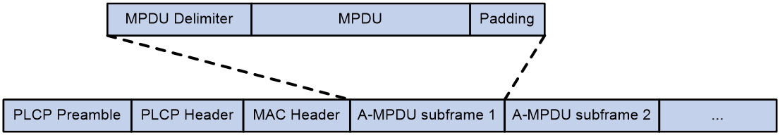
MPDU aggregation
A MAC Protocol Data Unit (MPDU) is a data frame in 802.11 format. MPDU aggregation aggregates multiple MPDUs into one aggregate MPDU (A-MPDU) to reduce additional information, ACK frames, and Physical Layer Convergence Procedure (PLCP) header overhead. This improves network throughput and channel efficiency.
All MPDUs in an A-MPDU must have the same QoS priority, source address, and destination address.
Figure 1 A-MPDU format
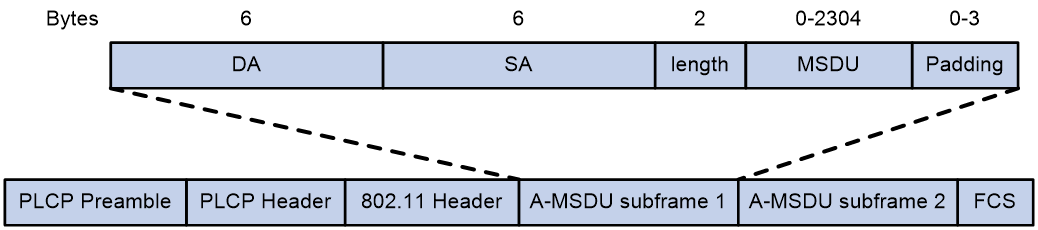
MSDU aggregation
An AP or client encapsulates a MAC Service Data Unit (MSDU) with an Ethernet header, and then converts the frame into 802.11 format for forwarding.
MSDU aggregation aggregates multiple MSDUs into one aggregate MSDU (A-MSDU) to reduce PLCP preamble, PLCP header, and MAC header overheads. This improves network throughput and frame forwarding efficiency.
All MSDUs in an A-MSDU must have the same QoS priority, source address, and destination address. When a device receives an A-MSDU, it restores the A-MSDU to multiple MSDUs for processing.
Figure 2 A-MSDU format
Short GI
http://en.wikipedia.org/wiki/802.11 OFDM fragments frames to data blocks for transmission. It uses GI to ensure that the data block transmissions do not interfere with each other and are immune to transmission delays.
The GI used by 802.11a/g is 800 ns. http://en.wikipedia.org/wiki/802.11n supports a short GI of 400 ns, which provides a 10% increase in data rate.
Both the 20 MHz and 40 MHz bandwidth modes support short GI.
LDPC
802.11n introduces the Low-Density Parity Check (LDPC) mechanism to increase the signal-to-noise ratio and enhance transmission quality. LDPC takes effect only when both ends support LDPC.
STBC
The Space-Time Block Coding (STBC) mechanism enhances the reliability of data transmission and does not require clients to have high transmission rates.
MSC indexes
802.11n clients use the rate corresponding to the MCS index to send unicast frames. Non-802.11n clients use the 802.11a/b/g rate to send unicast frames.
The client dot11n-only feature
The client dot11n-only feature enables an AP to accept only 802.11n and 802.11ac clients. Use this feature to prevent low-speed 802.11a/b/g clients from decreasing wireless data transmission performance.
802.11n bandwidth mode
802.11n uses the channel structure of 802.11a/b/g, but it increases the number of data subchannels in each 20 MHz channel to 52. This improves data transmission rate.
802.11n binds two adjacent 20 MHz channels to form a 40 MHz channel (one primary channel and one secondary channel). This provides a simple way to double the data rate.
The bandwidth for a radio varies by bandwidth mode configuration and chip capability.
MIMO modes
Multiple-input and multiple-output (MIMO) enables a radio to send and receive wireless signals through multiple spatial streams. This improves system capacity and spectrum usage without requiring higher bandwidth.
A radio can operate in one of the following MIMO modes:
· 1x1—Sends and receives wireless signals through one spatial stream.
· 2x2—Sends and receives wireless signals through two spatial streams.
· 3x3—Sends and receives wireless signals through three spatial streams.
· 4x4—Sends and receives wireless signals through four spatial streams.
· 5x5—Sends and receives wireless signals through five spatial streams.
· 6x6—Sends and receives wireless signals through six spatial streams.
· 7x7—Sends and receives wireless signals through seven spatial streams.
· 8x8—Sends and receives wireless signals through eight spatial streams.
Number of spatial streams supported by a radio varies by device model.
Energy saving
The energy saving feature enables an AP to automatically change the MIMO mode of a radio to 1x1 if no clients associate with the radio.
802.11n protection
When both 802.11n and non-802.11n clients exist in a WLAN, transmission collision might occur because they use different modulation modes. 802.11n protection can avoid such avoidance. It enables 802.11n devices to send RTS/CTS or CTS-to-self packets to inform non-802.11n clients to defer access to the medium.
802.11n devices send RTS/CTS or CTS-to-self packets before sending data only when non-802.11n signals are detected on the channel.
802.11n protection automatically takes effect when non-802.11n clients associate with an 802.11n 802.11ac, or 802.11ax AP.
|
|
NOTE: 802.11n devices refer to 802.11n, 802.11ac, and 802.11ax devices. |
The smart antenna feature
|
|
IMPORTANT: · Support for this feature depends on the AP model. · This feature is applicable only to 802.11n and 802.11ac radios. |
The smart antenna feature enables an AP to automatically adjust the antenna parameters based on the client location and channel information to improve signal quality and stability.
You can configure a radio to operate in one of the following smart antenna modes:
· auto—Uses the high availability mode for audio and video packets, and uses the high throughput mode for other packets.
· high-availability—Applicable to WLANs that require stable bandwidth, this mode reduces noise and interference impacts, and provides guaranteed bandwidth for clients.
· high-throughput—Applicable to WLANs that require high performance, this mode enhances signal strength and association capability.
802.11ac functions
|
|
IMPORTANT: When you configure 802.11ac functions for an AP, your configuration fails if another user is configuring 802.11ac functions for the same AP. |
Based on 802.11n, 802.11ac further increases the data transmission rate and improves the network performance by providing higher bandwidth, more spatial streams, and more advanced modulation schemes.
NSSs
If the AP supports an NSS, it supports all VHT-MCS indexes for the NSS.
802.11ac clients use the rate corresponding to the VHT-MCS index for the NSS to send unicast frames. Non-802.11ac clients use the 802.11a/b/g/n rate to send unicast frames.
Client dot11ac-only
To prevent low-speed 802.11a/b/g/n clients from decreasing wireless data transmission performance, you can enable the client dot11ac-only feature for an AP to accept only 802.11ac clients.
802.11ac bandwidth mode
802.11ac uses the channel structure of 802.11n and increases the maximum bandwidth from 40 MHz to 80 MHz/160MHz. 802.11ac can bind two adjacent 20 MHz channels to form a 40 MHz channel, bind two adjacent 40 MHz channels to form an 80 MHz channel, and bind two adjacent 80 MHz channels to form a 160 MHz channel.
Figure 3 802.11ac bandwidth modes

802.11ax functions
|
|
IMPORTANT: · When you configure 802.11ax functions for an AP, your configuration fails if another user is configuring 802.11ax functions for the same AP. · Some Intel wireless NICs might fail to detect the wireless signals sent by 802.11ax radios. In this scenario, update the NIC driver. |
NSS
Non-802.11ax clients use the 802.11a/b/g/n/ac rate to send unicast frames.
If an AP supports an NSS, it supports all HE-MCS indexes for the NSS. 802.11ax clients that use the rate corresponding to the HE-MCS index for the NSS to send unicast frames.
If you do not set a multicast NSS, 802.11ax clients and the AP use the 802.11a/b/g/n/ac multicast rate to send multicast frames. If you set a multicast NSS and specify an HE-MCS index, the following situations occur:
· The AP and clients use the rate corresponding to the HE-MCS index to send multicast frames if all clients are 802.11ax clients.
· The AP and clients use the 802.11a/b/g/n/ac multicast rate to send multicast frames if any non-802.11ax clients exist.
The maximum supported NSS cannot be smaller than the maximum mandatory NSS and the multicast NSS cannot be greater than the maximum mandatory NSS.
The maximum mandatory NSS or supported NSS determines a range of 802.11 rates. For example, if the maximum mandatory NSS is 5, rates corresponding to HE-MCS indexes for NSSs 1 through 5 will be 802.11ax mandatory rates.
802.11ax bandwidth mode
802.11ax uses the channel structure of 802.11n and increases the maximum bandwidth from 40 MHz to 160 MHz. 802.11ax can bind two adjacent 20/40/80 MHz channels to form a 40/80/160 MHz channel. 802.11gax supports only 20 MHz and 40 MHz.
Figure 4 802.11ax bandwidth modes

802.11be functions
|
|
NOTE: · If multiple users log in to the AC to configure 802.11be functions for an AP, only one user can successfully configure the AP. · If some Intel wireless NICs cannot scan for wireless signals emitted by 802.11be radios, try updating the NIC driver. |
NSS
When an 802.11be client comes online, it will use the modulation and coding scheme (MCS) represented by the EHT-MCS index corresponding to the NSS to transmit unicast data.
If multicast NSS is not configured, the 802.11be client and AP will use the modulation and coding scheme represented by the multicast rate or multicast MCS to send multicast data.
If multicast NSS is configured and all clients are 802.11be clients, the AP and clients will use the modulation and coding scheme represented by the EHT-MCS index to transmit multicast data.
Follow these restrictions and guidelines:
· The configured maximum 802.11be mandatary NSS number indicates the maximum mandatary NSS for the 802.11be radio, meaning the mandatary NSS for this radio is in the range of 1 to number.
· The configured maximum 802.11be supported NSS number indicates the maximum supported NSS for the 802.11be radio, meaning the supported NSS for this radio is in the range of 1 to number.
· The configured 802.11be multicast NSS number indicates the NSS number used by the radio to send 802.11be multicast packets. The configured EHT-MCS index indicates the EHT-MCS index used by the radio to send 802.11be multicast packets corresponding to the NSS.
802.11be channel bandwidth
802.11be adopts the channel bandwidth allocation method from 802.11n, achieving wider bandwidth by combining adjacent channels. In 802.11be, two adjacent 20 MHz channels can be combined to form a 40 MHz channel, and similarly, 80 MHz and 160 MHz channels can be combined.
According to the protocol, the actual working bandwidth of a radio is divided into two parts. The first part's position is determined by the primary channel, and the second part's position is determined by the secondary channel. The primary channel transmits data frames and all control and management frames. The secondary channel is bundled with the primary channel and only transmits data frames.
Figure 5 802.11be bandwidth modes

MRU
Multiple Resource Unit (MRU) is a technology that increases the spectral resource usage rate, mainly used in multi-user scenarios.
In Wi-Fi6, each user can only use one RU. In Wi-Fi7, the concept of MRU is introduced to allow a single user to use multiple RUs. As shown in Figure 6, under the same bandwidth, MRU allows a single client to occupy multiple RUs simultaneously when data is being transmitted to two users at the same time. This improves spectral resource usage and reduces latency. In Wi-Fi 6, a single client can only use the single RU resource allocated to it, resulting in a waste of spectral resources.
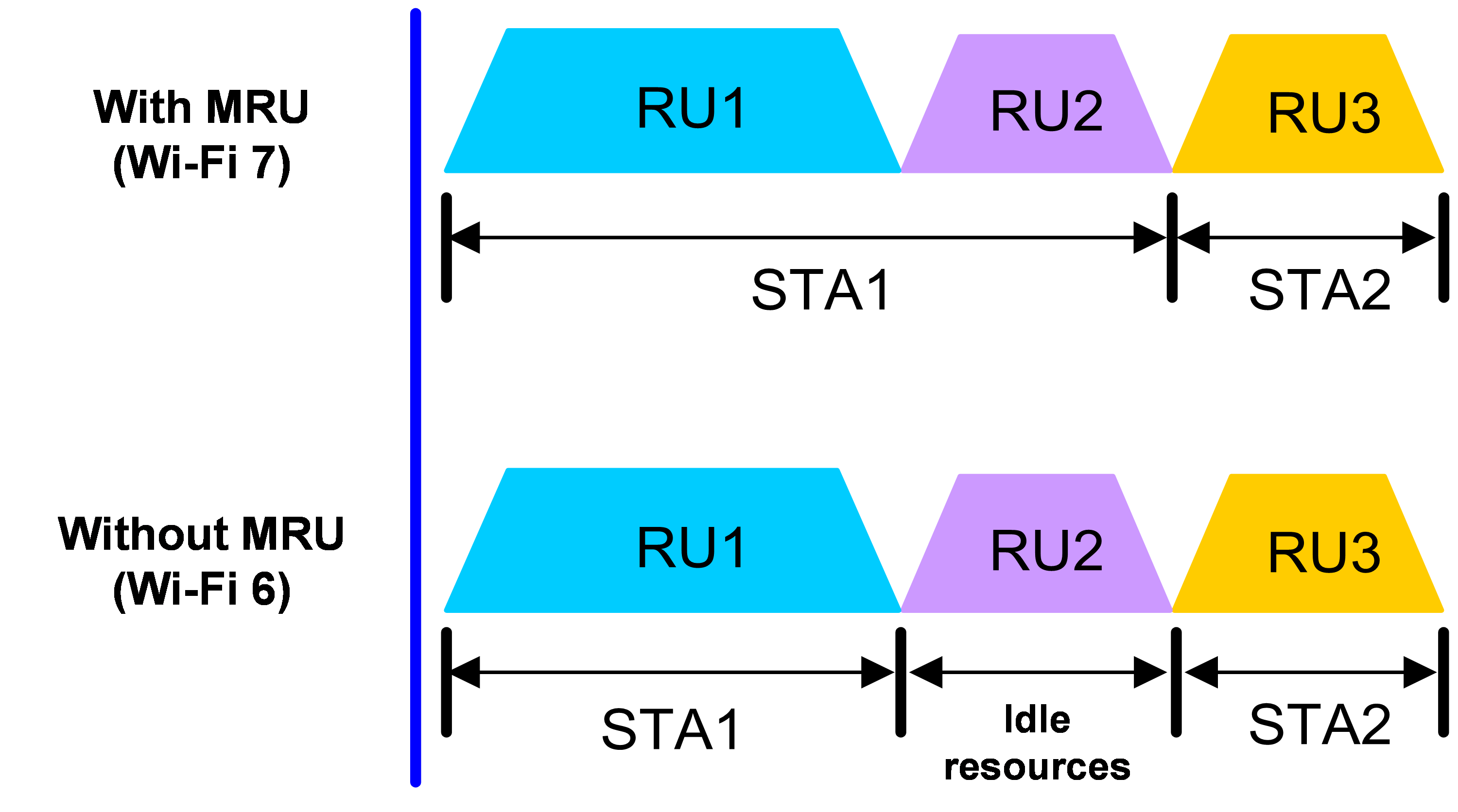
Preamble puncturing
The preamble puncturing technology enables data transmission using discontinuous channels to improve channel utilization efficiency. It is mainly used in scenarios with channel interference.
Without preamble puncturing, as shown in Figure 7, if the bandwidth mode is 80 MHz and interference is encountered on channel 56, the system uses the 20 MHz bandwidth mode instead for transmission. With preamble puncturing enabled, as shown in Figure 8, the interfered portion (channel 56) is punctured and shielded, and the remaining channels 52, 60, and 64 are bundled together for information transmission. Although the AP is still working in the 80 MHz bandwidth mode, the interfered channel is put in Null state (idle state) in actual transmission.
Preamble static puncturing refers to the software designating the puncturing positions based on the bandwidth mode and the position of the primary channel.
Figure 7 Without preamble puncturing
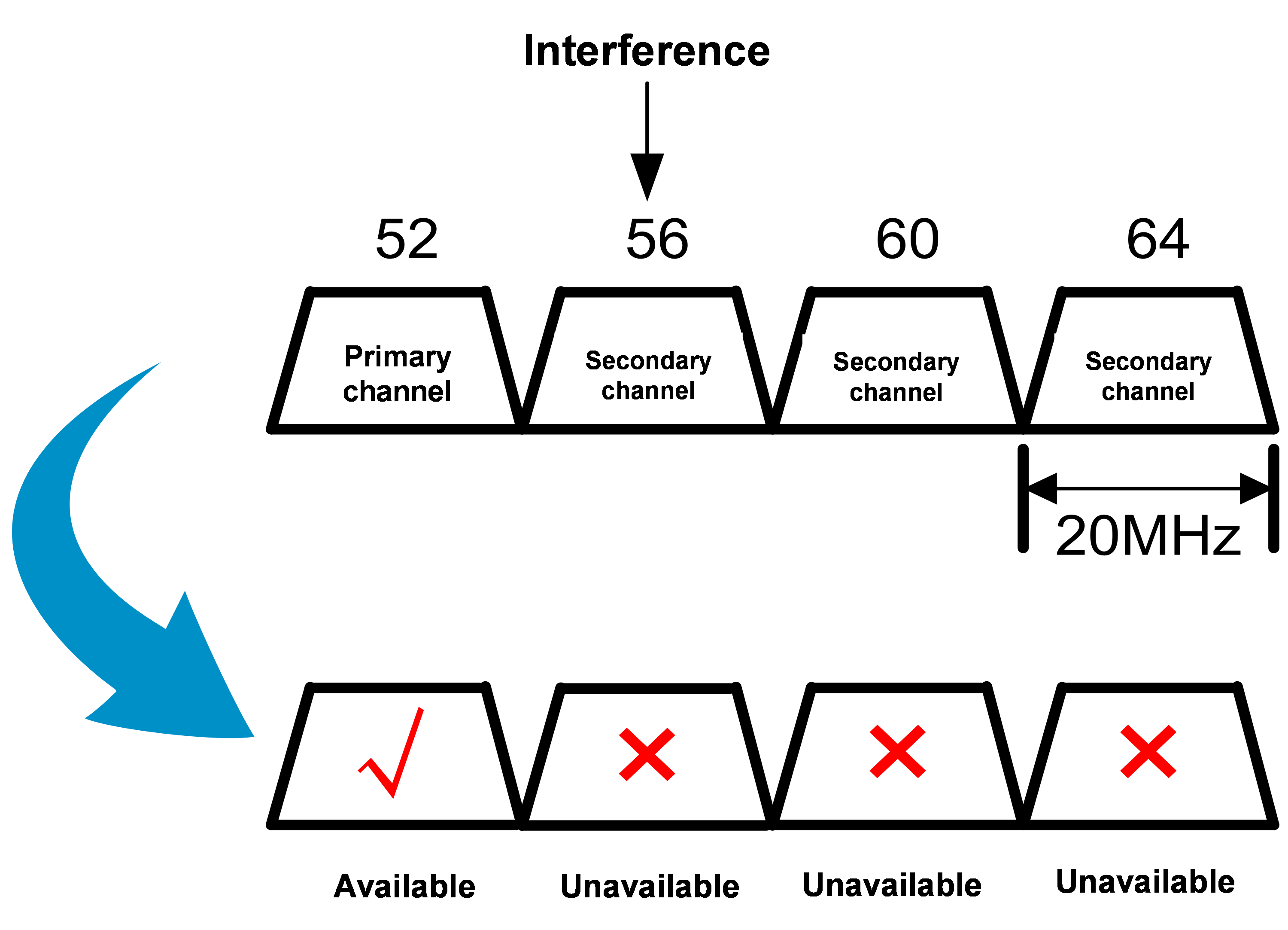
Figure 8 With preamble puncturing
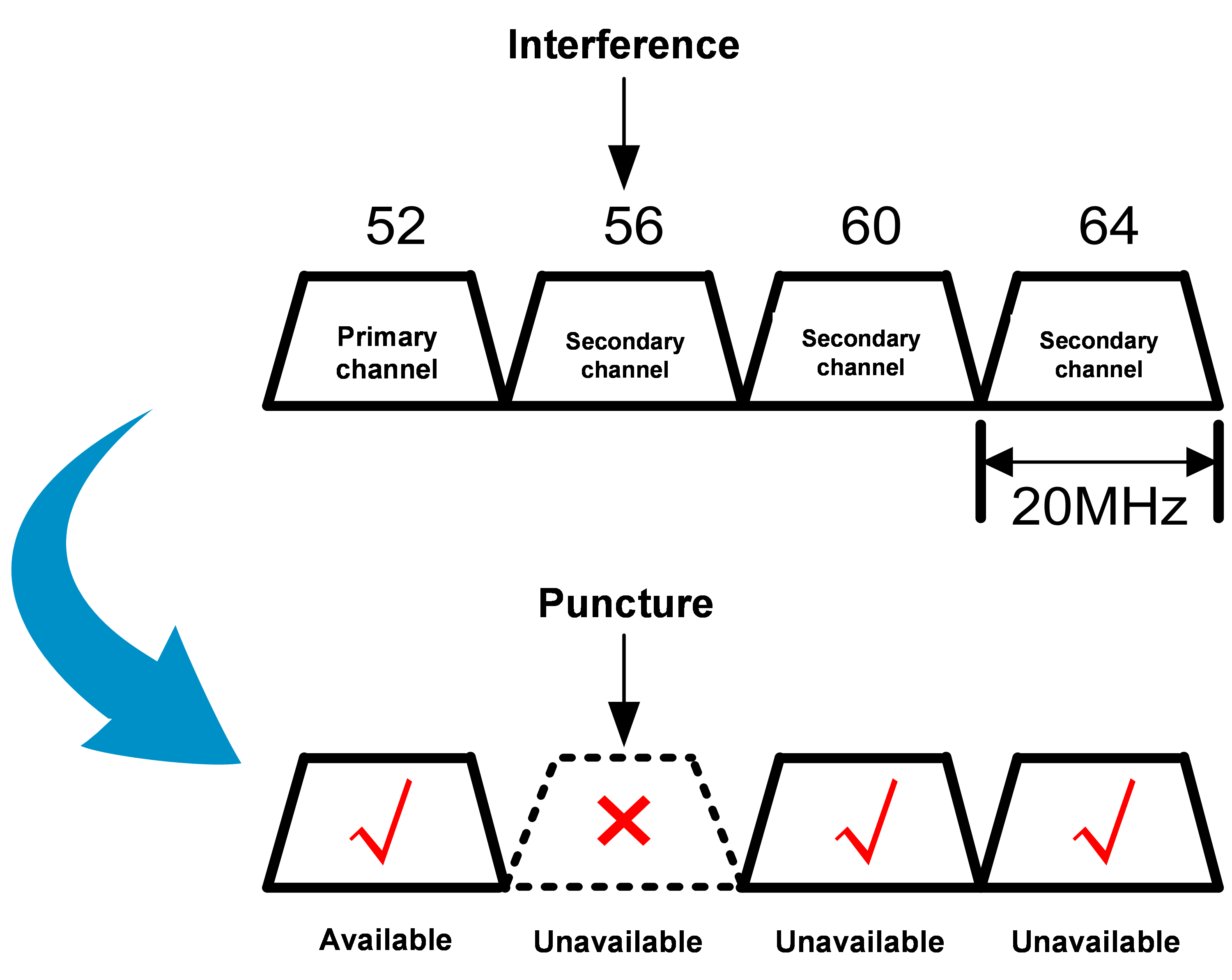
Preamble puncturing takes effect only when the bandwidth mode is 80 MHz or higher.
Preamble puncturing is available only for 802.11be, 802.11gbe, and 802.11abe radios. Changing the radio mode to a lower one cancels the configuration.
Band navigation
As shown in Figure 9, band navigation is enabled in the WLAN. Client 1 is associated with the 5 GHz radio and Client 2 is associated with the 2.4 GHz radio. When the dual-band client Client 3 requests to associate with the 2.4 GHz radio, the AP rejects Client 3 and directs it to the 5 GHz radio.
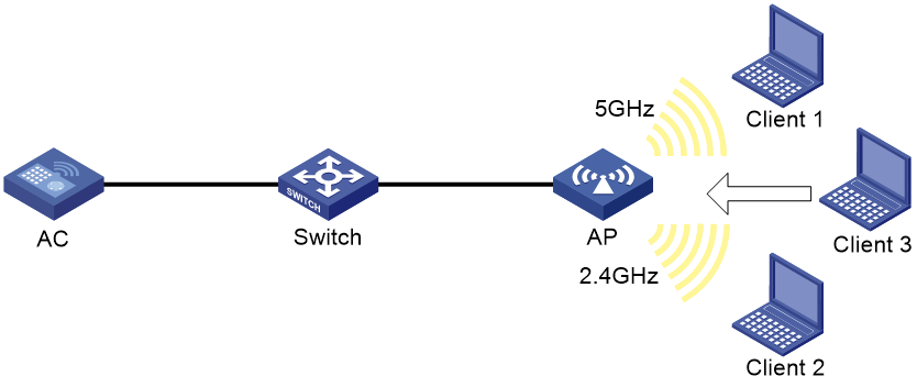
Wireless security
WIPS
Wireless Intrusion Prevention System (WIPS) helps you monitor your WLAN, detect attacks and rogue devices, and take countermeasures. WIPS provides a complete solution for WLAN security.
WIPS contains the network management module, the AC, and sensors (APs enabled with WIPS). They provide the following functions:
· The sensors monitor the WLAN, collect channel information, and report the information to the AC for further analysis.
· The AC determines attacks and rogue devices, takes countermeasures, and triggers alarms.
· The network management module allows you to configure WIPS in the Web interface. It provides configuration management, report generation, and alarm management functions.
WIPS provides the following features:
· Attack detection—WIPS detects attacks by listening for 802.11 frames and triggers alarms to notify the administrator.
· Device classification—WIPS identifies wireless devices by listening for 802.11 frames and classifies the devices based on the classification rules.
· Countermeasures—WIPS enables you to take countermeasures against rogue devices.
Enabling WIPS
Before enabling WIPS for a radio of an AP, you must add the AP to a virtual security domain (VSD).
VSD
You can apply a classification policy, attack detection policy, signature policy, or countermeasure policy to a VSD to enable the policy to take effect on the radios in the VSD.
Device classification
Classification policy
You can enable WIPS to classify devices by using either of the following methods:
· Automatic classification—WIPS automatically classifies devices by adding the MAC addresses, OUIs, or SSIDs of the devices to the specified lists. WIPS also allows you to classify APs by using user-defined AP classification rules.
· Manual classification—You manually specify a category for a device. Manual classification is applicable only to APs.
If you configure both automatic classification and manual classification, manual classification takes effect.
AP classification
As shown in Table 37, WIPS classifies detected APs according to the predefined classification rules.
|
Category |
Description |
Classification rule |
|
Authorized AP |
An AP that is permitted in the WLAN. |
· Not in the prohibited device list. · Has been connected to the AC. · Configured as an authorized AP. |
|
Rogue AP |
An AP that cannot be used in the WLAN. |
· In the prohibited device list. · Not in the OUI configuration file. · Configured as a rogue AP. |
|
Misconfigured AP |
An AP that can be used in the WLAN but has incorrect configuration. |
· In the permitted device list but with an incorrect SSID. · Not in the prohibited device list but in the OUI configuration file. · In the trusted OUI list or permitted device list but not connected to the AC. |
|
External AP |
An AP that is in an adjacent WLAN. |
N/A |
|
Ad hoc |
An AP operating in Ad hoc mode. WIPS detects Ad hoc APs by listening to beacon frames. |
N/A |
|
Potential-authorized AP |
An AP that is possibly authorized. |
Not in any of the following lists: · Permitted device list. · Prohibited device list. · Trusted OUI list. |
|
Potential-rogue AP |
An AP that is possibly a rogue AP. |
Has incorrect wireless configuration and is not in any of the following lists: · Permitted device list. · Prohibited device list. · Trusted OUI list. If the wired port on an AP has been connected to the network, the AP is a rogue AP. |
|
Potential-external AP |
An AP that is possibly an external AP. |
· Has incorrect wireless service configuration. · The wired port has not been connected to the network. · Not in any of the following lists: ¡ Permitted device list. ¡ Prohibited device list. ¡ Trusted OUI list. |
|
Uncategorized AP |
An AP whose category cannot be determined. |
N/A |
WIPS classifies detected APs by following the procedure shown in Figure 10.
Figure 10 AP classification flow
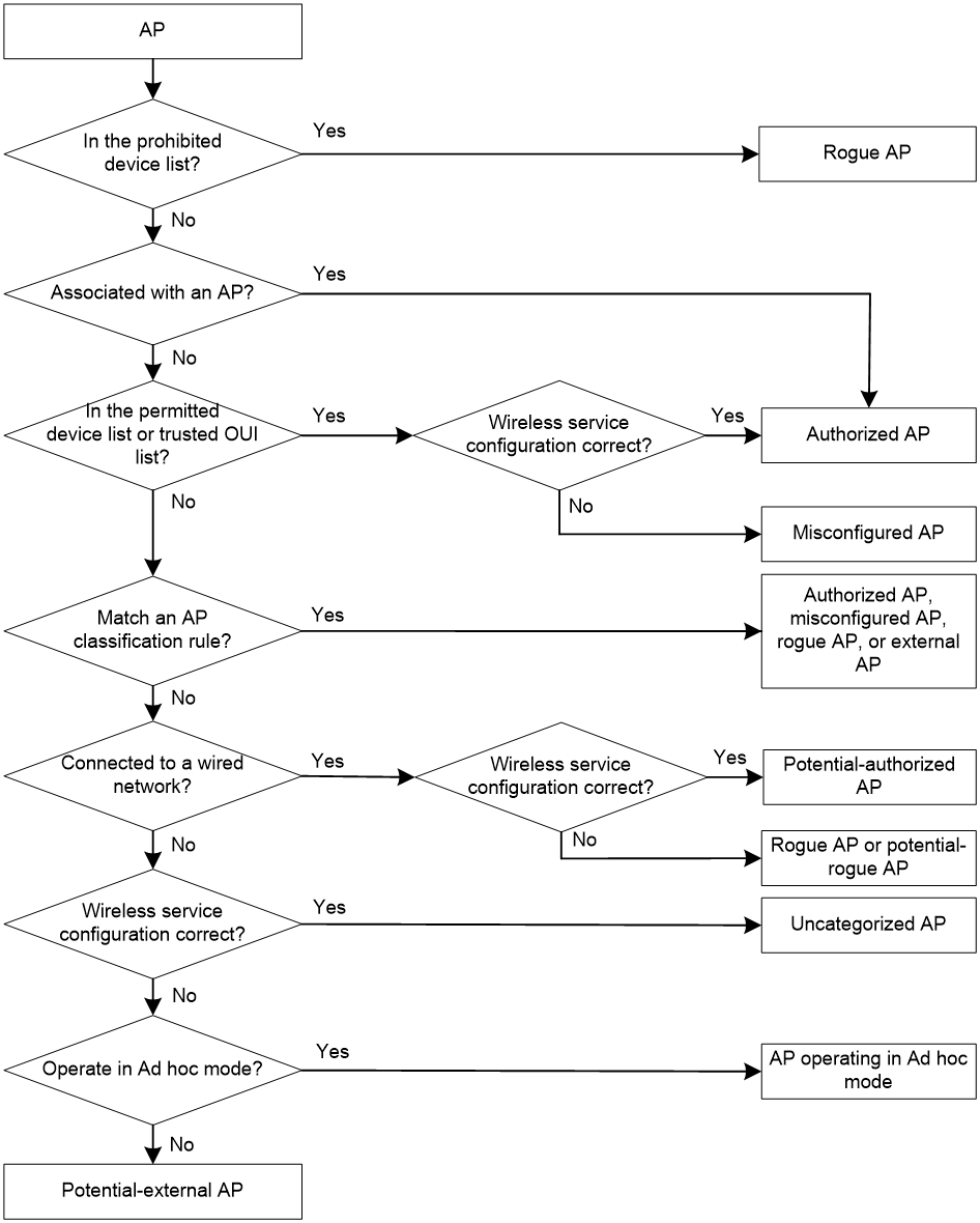
Client classification
As shown in Table 38, WIPS classifies detected clients according to the predefined classification rules.
Table 38 Client classification
|
Category |
Description |
Classification rule |
|
Authorized client |
A client that is permitted in the WLAN. |
· In the permitted device list and associated with an authorized AP. · Has passed authentication and is associated with an authorized AP. |
|
Unauthorized client |
A client that cannot be used in the WLAN. |
· In the prohibited device list. · Associated with a rogue AP. · Not in the OUI configuration file. |
|
Misassociated client |
A client that is associated with an unauthorized AP. |
In the permitted device list but associated with an unauthorized AP. A misassociated client might bring security threats to the network. |
|
Uncategorized client |
A client whose category cannot be determined. |
N/A |
WIPS classifies detected clients by following the procedure shown in Figure 11.
Figure 11 Client classification flow
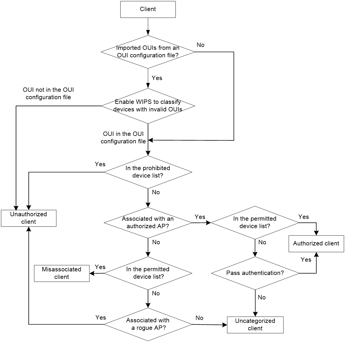
Attack detection
WIPS detects attacks by listening to 802.11 frames and triggers alarms to notify the administrator.
Device entry attack detection
Attackers can send invalid packets to WIPS to increase processing costs. WIPS periodically examines the learned device entries to determine whether to rate limit device entry learning. If the number of AP or client entries learned within the specified interval exceeds the threshold, WIPS triggers an alarm and stops learning new entries.
Flood attack detection
An AP might be facing a flood attack if it receives a large number of same-type frames within a short period of time. To prevent the AP from being overwhelmed, WIPS periodically examines incoming packet statistics, and alarms when it detects a suspicious flood attack. WIPS can detect the following flood attacks:
· Probe request/association request/reassociation request flood attack—Floods the association table of an AP by imitating many clients sending probe requests/association requests/reassociation requests to the AP.
· Authentication request flood attack—Floods the association table of an AP by imitating many clients sending authentication requests to the AP.
· Beacon flood attack—Floods beacon frames imitating a large number of fake APs to interrupt client association.
· Block Ack flood attack—Floods Block Ack frames to the AP to interrupt the operation of the Block Ack mechanism.
· RTS/CTS flood attack—Floods RTS/CTS frames to reserve the RF medium and force other wireless devices sharing the RF medium to hold back their transmissions. This attack takes advantage of vulnerabilities of the virtual carrier mechanism.
· Broadcast/unicast deauthentication flood attack—Spoofs deauthentication frames from the AP to the associated clients to disassociate the clients from the AP. This attack can rapidly terminate wireless services to multiple clients.
· Broadcast/unicast disassociation flood attack—Spoofs disassociation frames from the AP to the associated clients to disassociate the clients from the AP. This attack can rapidly terminate wireless services to multiple clients.
· EAPOL-start flood attack—Exhausts the AP's resources by imitating many clients sending EAPOL-start frames defined in IEEE 802.1X to the AP.
· Null data flood attack—Spoofs null data frames from a client to the AP. The AP determines that the client is in power save mode and buffers frames for the client. When the aging time of the buffered frames expires, the AP discards the frames. This interrupts the client's communication with the AP.
· EAPOL-logoff flood attack—The IEEE 802.1X standard defines the authentication protocol using Extensible Authentication Protocol over LANs (EAPOL). A client needs to send an EAPOL-logoff frame to terminate the session with an AP. The EAPOL-logoff frames are not authenticated, and an attacker can spoof EAPOL-logoff frames to disassociate a client.
· EAP-success/failure flood attack—In a WLAN using 802.1X authentication, an AP sends an EAP-success or EAP-failure frame to a client to inform authentication success or failure. An attacker can spoof the MAC address of an AP to send EAP-success or EAP-failure frames to a client to disrupt the authentication process.
Malformed packet detection
WIPS determines that a frame is malformed if the frame matches the criteria shown in Table 39, and then it triggers alarms and logs. WIPS can detect 16 kinds of malformed packets.
Table 39 Malformed frame match criteria
|
Detection type |
Applicable frames |
Match criteria |
|
Duplicate IE detection |
All management frames |
Duplicate IE. This type of detection is not applicable to vendor-defined IEs. |
|
FATA-Jack detection |
Authentication frames |
The value of the authentication algorithm number is 2. |
|
Abnormal IBSS and ESS setting detection |
· Beacon frames · Probe response frames |
Both IBSS and ESS are set to 1. |
|
Invalid source address detection |
All management frames |
· The TO DS is 1, indicating that the frame is sent to the AP by a client. · The source MAC address of the frame is a multicast or broadcast address. |
|
Malformed association request frame detection |
Association request frames |
The frame length is 0. |
|
Malformed authentication request frame detection |
Authentication request frames |
· The authentication algorithm number does not conform to the 802.11 protocol and is larger than 3. · The authentication transaction sequence number is 1 and the status code is not 0. · The authentication transaction sequence number is larger than 4. |
|
Invalid deauthentication code detection |
Deauthentication frames |
The reason code is 0 or is in the range of 67 to 65535. |
|
Invalid disassociation code detection |
Disassociation frames |
The reason code is 0 or is in the range of 67 to 65535. |
|
Malformed HT IE detection |
· Beacon frames · Probe responses · Association responses · Reassociation requests |
· The SM power save value for the HT capabilities IE is 2. · The secondary channel offset value for the HT operation IE is 2. |
|
Invalid IE length detection |
All management frames |
The IE length does not conform to the 802.11 protocol. |
|
Invalid packet length detection |
All management frames |
The remaining length of the IE is not zero after the packet payload is resolved. |
|
Malformed probe response frame detection |
Probe response frames |
The frame is not a mesh frame and its SSID length is 0. |
|
Oversized EAPOL key detection |
EAPOL-Key frames |
The TO DS is 1 and the length of the key is larger than 0. |
|
Oversized SSID detection |
· Beacon frames · Probe requests · Probe responses · Association request frames |
The SSID length is larger than 32. |
|
Redundant IE detection |
All management frames |
The IE is not a necessary IE to the frame and is not a reserved IE. |
|
Oversized duration detection |
· Unicast management frames · Unicast data frames · RTS, CTS, and ACK frames |
The packet duration value is larger than the specified threshold. |
Attack detection
· Spoofing attack detection
In a spoofing attack, the attacker sends frames on behalf of another device to threaten the network. WIPS supports detection of the following spoofing attacks:
¡ Frame spoofing—A fake AP spoofs an authorized AP to send beacon or probe response frames to induce clients to associate with it.
¡ AP MAC address spoofing—A client spoofs an authorized AP to send deauthentication or disassociation frames to other clients. This can cause the clients to go offline and affect the correct operation of the WLAN.
¡ Client MAC address spoofing—A fake AP spoofs an authorized client to associate with an authorized AP.
When the RC4 encryption algorithm, used by the WEP security protocol, uses an insecure IV, the WEP key is more likely to be cracked. Such an insecure IV is called a weak IV. WIPS prevents this kind of attack by detecting the IV in each WEP packet.
· Windows bridge detection
When a wireless client connected to a wired network establishes a Windows bridge through the wired NIC, the client can bridge an external AP with the internal network. This might bring security problems to the internal network. WIPS detects Windows bridges by analyzing data frames sent by associated clients.
· Detection on clients with the 40 MHz bandwidth mode disabled
802.11n devices support both the 20 MHz and 40 MHz bandwidth modes. If the 40 MHz bandwidth mode is disabled on a client, other clients associated with the same AP as the client must also use the 20 MHz bandwidth. This affects network throughput and efficiency.
WIPS detects such clients by detecting probe request frames sent by the clients.
Omerta is a DoS attack tool based on the 802.11 protocol. It sends disassociation frames with the reason code 0x01 to disassociate clients. Reason code 0x01 indicates an unknown disassociation reason. WIPS detects Omerta attacks by detecting the reason code of each disassociation frame.
· Unencrypted device detection
An authorized AP or client that is transmitting unencrypted frames might bring security problems to the network. WIPS detects unencrypted devices by analyzing the frames sent the by authorized APs or clients.
An attacker sets up a rogue AP with the same SSID as a hotspot to lure the clients to associate with it. After the clients associate with the malicious AP, the attacker initiates further attacks to obtain client information.
You can configure a hotspot file to enable WIPS to detect hotspot attacks.
An AP operating in HT-greenfield mode might cause collisions, errors, and retransmissions because it cannot communicate with 802.11a/b/g devices. WIPS detects HT-greenfield APs by analyzing the beacon frames or probe response frames sent by APs.
· Association/reassociation DoS attack detection
An association/reassociation DoS attack floods the association table of an AP by imitating many clients sending association requests to the AP. When the number of entries in the table reaches the upper limit, the AP cannot process requests from legitimate clients.
In an MITM attack, the attacker sets up a rogue AP and lures a client to associate with it. Then the rogue AP spoofs the MAC address of the client to associate with the authorized AP. When the client and the authorized AP communicate, the rogue AP captures packets from both the client and the authorized AP. The rogue AP might modify the frames and obtain the frame information. WIPS detects MITM attacks by detecting clients that are disassociated from an authorized AP and associated with a honeypot AP.
An attacker might intrude on the internal networks through a wireless bridge. When detecting a wireless bridge, WIPS generates an alarm. If the wireless bridge is in a mesh network, WIPS records the mesh link.
· AP channel change detection
WIPS detects the channel change events for APs in the WLAN.
· Broadcast disassociation/deauthentication attack detection
An attacker spoofs a legitimate AP to send a broadcast disassociation or deauthentication frame to log off all clients associated with the AP.
· AP impersonation attack detection
In an AP impersonation attack, a malicious AP that has the same BSSID and ESSID as a legitimate AP lures the clients to associate with it. Then this impersonating AP initiates hotspot attacks or fools the detection system.
WIPS detects AP impersonation attacks by detecting the interval at which an AP sends beacon frames.
WIPS detects the number of APs in the WLAN and triggers an alarm for an AP flood attack when the number of APs exceeds the specified threshold.
In a honeypot AP attack, the attacker sets up a malicious AP to lure clients to associate with it. The SSID of the malicious AP is similar to the SSID of a legitimate AP. After a client associates with a honeypot AP, the honeypot AP initiates further attacks such as port scanning or fake authentication to obtain client information.
WIPS detects honeypot APs by detecting SSIDs of external APs. If the similarity between the SSID of an external AP and the SSID of a legitimate AP reaches the specified threshold, WIPS generates an alarm.
An attacker spoofs the MAC address of a client to send power save on frames to an AP. The AP caches the frames for the client. The attacked client cannot receive data frames because the AP determines that the client is still in power save mode. When the aging time of the cached frames expires, the AP discards the frames. WIPS detects power save attacks by determining the ratio of power save on frames to power save off frames.
A soft AP refers to a client that acts as an AP and provides wireless services. An attacker can access the internal network through a soft AP and then initiate further attacks. WIPS detects soft APs by detecting the interval at which a device switches its roles between client and AP.
· Prohibited channel detection
After you configure a permitted channel list and enable prohibited channel detection, WIPS determines that channels that are not in the permitted channel list are prohibited channels.
User-defined attack detection based on signatures
WIPS provides user-defined attack detection based on signatures. A signature contains a packet identification method and actions to take on the matching packets. The sensor matches the detected packets against the signature, and takes actions defined in the signature if a packet matches the signature.
A signature can contain a maximum of six subsignatures, which can be defined based on the frame type, MAC address, serial ID, SSID length, SSID, and frame pattern. A packet matches a signature only when it matches all the subsignatures in the signature.
Countermeasure policies
Rogue devices are susceptible to attacks and might bring security problems to the WLAN. WIPS enables you to take countermeasures against rogue devices.
Alarm-ignored device list
For wireless devices in an alarm-ignored device list, WIPS only monitors them but does not trigger any alarms.
Whitelist and blacklist features
· Whitelist—Contains the MAC addresses of all clients allowed to access the WLAN. Frames from clients not in the whitelist are discarded. This list is manually configured.
· Static blacklist—Contains the MAC addresses of clients forbidden to access the WLAN. This list is manually configured.
· Dynamic blacklist—Contains the MAC addresses of clients forbidden to access the WLAN through specific APs within the specified aging time. A client is dynamically added to the list if an AP determines this client is a rogue client.
Applications
WLAN mesh
WLAN mesh allows APs to be wirelessly connected. The APs on a WLAN mesh network can be connected directly or over multiple hops. When one AP fails, the remaining APs can still communicate with each other. For users, a WLAN mesh network can provide the same good user experience as a traditional WLAN.
MP roles
APs on a WLAN mesh network are mesh points (MPs). MPs play the following roles:
· Single-purpose MP—Provides only mesh services.
· Mesh access point (MAP)—Provides both mesh and access services.
· Mesh portal point (MPP)—Provides a wired connection to a wired network.
Mesh profile
A mesh profile is a set of mesh protocol processing capabilities for an AP to operate on a mesh network. A mesh profile contains a mesh ID, the Authentication and Key Management mode, and the keepalive interval.
Before MPs can establish a mesh link, they need to discover each other and establish a peer relationship. MPs establish a peer relationship with each other only when their mesh profiles match.
Mesh policy
A mesh policy contains a set of mesh link setup and maintenance attributes. These attributes are the mesh link initiation feature, the probe request interval, the link rate mode, and the maximum number of mesh links. Only one mesh policy can be bound to a radio of an MP, and the policy takes effect on all mesh links on the radio.
By default, a system-defined mesh policy is bound to each radio. This system-defined mesh policy cannot be deleted or modified. To change the link setup and maintenance settings on a radio, you can bind a user-defined mesh policy to the radio to replace the system-defined mesh policy.
Mesh peer whitelist
Use a mesh peer whitelist to ensure that an MP establishes mesh links only with legitimate MPs.
An MP can establish peer relationships with any MP neighbors if you do not configure a whitelist.
WLAN multicast optimization
Overview
Multicast transmission has limitations and cannot meet the requirements for applications that are not sensitive to time delay but sensitive to data integrity. To address this issue, you can configure WLAN multicast optimization to enable an AP to convert multicast packets to unicast packets.
WLAN multicast optimization uses multicast optimization entries to manage traffic forwarding. The multicast optimization entries use the clients' MAC addresses as indexes. A multicast optimization entry records information about multicast groups that clients join, multicast sources from which clients receive traffic, multicast group version, and multicast optimization mode.
Each time a client joins a multicast group, the AP creates a multicast optimization entry for the multicast group. If multicast sources have been specified for a client when the client joins the multicast group, the AP also creates a multicast optimization entry for each multicast source. When a client leaves a multicast group or rejects a multicast source, the AP deletes the relevant multicast optimization entry for the client.
Aging time for multicast optimization entries
Configure an appropriate aging timer for multicast optimization entries. A long aging time consumes more system resources and affects the creation of new entries and a short aging time causes frequent entries generation and aging.
Multicast optimization policy
A multicast optimization policy defines the maximum number of clients that WLAN multicast optimization supports and defines the following actions an AP takes when the limit is reached:
· Unicast forwarding—Sends unicast packets converted from a multicast packet to only n (n equal to the specified threshold) clients that are randomly selected.
· Multicast forwarding—Forwards the multicast packet to all clients.
· Packet dropping—Drops the multicast packet.
If you do not specify an action, an AP performs unicast forwarding.
Multicast optimization entry limits
Limit for multicast optimization entries
You can limit the number of multicast optimization entries to save system resources.
When the number of multicast optimization entries reaches the limit, the AP stops creating new entries until the number falls below the limit
Limit for multicast optimization entries per client
You can limit the number of multicast optimization entries that an AP maintains for each client to prevent a client from occupying excessive system resources.
Rate limits for IGMP packets from clients
You can configure the maximum number of IGMP packets that an AP can receive from clients within the specified interval. The AP discards the excessive IGMP packets.
Bonjour gateway
Bonjour is a set of zero configuration network protocols developed by Apple Inc. based on Multicast DNS (mDNS) services. Bonjour is designed to make network configuration easier for users. It enables service devices to automatically advertise service information and enables clients to automatically discover service devices without obtaining information about the devices.
However, Bonjour supports only link-local multicast addresses. To address this issue, the AC can act as a Bonjour gateway to manage clients and service devices and forward mDNS packets across VLANs. This enables Bonjour to be applied in large-scale networks.
Bonjour gateway provides the following benefits through the snooping and caching of Bonjour service advertisements and the snooping and responding of Bonjour queries:
· mDNS traffic control.
· Inter-VLAN forwarding of mDNS packets.
Bonjour service advertisement snooping and caching
As shown in the following figure, Bonjour service advertisement snooping operates as follows:
1. Apple TV and Printer send service advertisements to advertise their service information.
2. Upon receiving the service advertisements, the Bonjour gateway caches them.
3. iPad requests the service of Apple TV or Printer.
4. The Bonjour gateway sends a response to iPad because the requested service is in the Bonjour cache.
Figure 12 Bonjour service advertisement snooping and caching
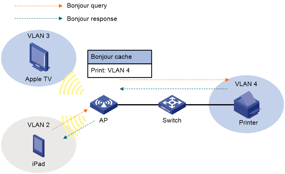
Bonjour query snooping and responding
As shown in the following figure, the Bonjour gateway performs the Bonjour query snooping and responding operation by using the following process if the service query it receives is not in the Bonjour cache:
1. Upon receiving a query for the printing service from a client (iPad in the figure), the AP sends the query to the Bonjour gateway (AC) through the CAPWAP tunnel.
2. The Bonjour gateway forwards the query to the configured service VLANs because it does not find a printing service entry in the Bonjour cache.
3. Upon receiving the query, the printer sends a response to the Bonjour gateway upon receiving the query.
4. The Bonjour gateway caches the response and forwards it to iPad.
Figure 13 Bonjour query snooping and responding
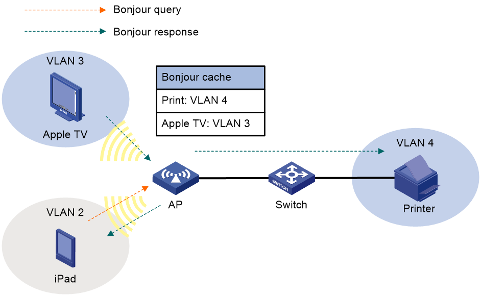
Bonjour service types
The service type is used to control Bonjour services under the Bonjour policy. Some default service types exist on the device, and users can also create new Bonjour service types. When creating new Bonjour service types, you need to specify the protocol and description information.
When Bonjour gateway is globally enabled and active query is enabled, activating a Bonjour service type will trigger an active query operation for that service type on the device.
When activating a Bonjour service type, you can specify the maximum number of SRV type resource entries that can be learned for that service type. If not specified, no limit is applied. When the service type is not activated, the device will delete all learned service resources of that type.
Table 40 Apple Bonjour protocols and service type strings
|
Name |
Service type strings |
|
afpovertcp |
AppleTalkFiling Protocol |
|
airplay |
Airplay |
|
airport |
Airport Base Station |
|
apple-sasl |
Apple Password Server |
|
daap |
Digital Audio Access Protocol |
|
dacp |
Digital Audio Control Protocol |
|
distcc |
Distributed Compiler |
|
dpap |
Digital Photo Access Protocol |
|
eppc |
Remote AppleEvents |
|
ftp |
File Transfer Protocol |
|
http |
Hypertext Transfer Protocol |
|
ica-networking |
Image Capture Sharing |
|
ichat |
iChat Instant Messaging Protocol |
|
ipp |
Internet Printing Protocol over HTTP |
|
ipps |
Internet Printing Protocol over HTTPS |
|
nfs |
Network File System |
|
pdl-stream |
PDL Data Stream |
|
printer |
Line Printer Daemon |
|
raop |
Remote Audio Output Protocol |
|
riousbprint |
Remote I/O USB Printer Protocol |
|
servermgr |
Server Admin |
|
ssh |
Secure Shell |
|
telnet |
Remote Login |
|
webdav |
WebDav File System |
|
workstation |
Workgroup Manager |
|
xserveraid |
Xerver RAID |
Bonjour policies
A Bonjour policy is used to control Bonjour service and VLAN access permissions. After configuring the service type and service VLAN in the Bonjour policy, apply the Bonjour policy to the specified locations (User profile view, AP view, AP group view, interface view, and service template view) to achieve the control function.
· Configure service type
The Bonjour gateway checks if the service type in the client's request matches the service type configured in the Bonjour policy. If no match is found, the query packet is discarded. For received response messages, the Bonjour gateway checks the service type, IP address, and instance name, and only forwards response packets that comply with all Bonjour policy configurations.
· Configure service VLAN
The service VLAN is used to limit the scope of Bonjour services. The device will only forward query and response packets when the VLAN of the Bonjour service requested by the client is in the device's service VLAN list.
Client probing
After you enable client probing on the radio of an AP, the AP scans channels to collect client information. You can view the client information on the Monitoring > Client Proximity Sensor page.
Network configuration
Interfaces
Interfaces
You can view interface traffic statistics information and configure basic interface settings.
Configuring the interface duplex mode and speed
You can configure an Ethernet interface to operate in one of the following duplex modes:
· Full-duplex mode—The interface can send and receive packets simultaneously.
· Half-duplex mode—The interface can only send or receive packets at a given time.
· Autonegotiation mode—The interface negotiates a duplex mode with its peer.
You can set the speed of an Ethernet interface or enable it to automatically negotiate a speed with its peer.
Configuring jumbo frame support
Jumbo frames are frames larger than a device-specific size and are typically received by an Ethernet interface during high-throughput data exchanges, such as file transfers. The device-specific size varies by device model.
The Ethernet interface processes jumbo frames in the following ways:
· When the Ethernet interface is configured to deny jumbo frames, the Ethernet interface discards jumbo frames.
· When the Ethernet interface is configured with jumbo frame support, the Ethernet interface performs the following operations:
¡ Processes jumbo frames within the specified length.
¡ Discards jumbo frames that exceed the specified length.
Configuring generic flow control on an Ethernet interface
To avoid dropping packets on a link, you can enable generic flow control at both ends of the link. When traffic congestion occurs at the receiving end, the receiving end sends a flow control (Pause) frame to ask the sending end to suspend sending packets. Generic flow control includes the following types:
· TxRx-mode generic flow control—With TxRx-mode generic flow control enabled, an interface can both send and receive flow control frames:
¡ When congestion occurs, the interface sends a flow control frame to its peer.
¡ When the interface receives a flow control frame from its peer, it suspends sending packets to its peer.
· Rx-mode generic flow control—With Rx-mode generic flow control enabled, an interface can receive flow control frames, but it cannot send flow control frames:
¡ When congestion occurs, the interface cannot send flow control frames to its peer.
¡ When the interface receives a flow control frame from its peer, it suspends sending packets to its peer.
To handle unidirectional traffic congestion on a link, configure Rx-mode generic flow control at one end and TxRx-mode generic flow control at the other end. To enable both ends of a link to handle traffic congestion, configure TxRx-mode generic flow control at both ends.
Storm suppression
The storm suppression feature ensures that the size of a particular type of traffic (broadcast, multicast, or unknown unicast traffic) does not exceed the threshold on an interface. When the broadcast, multicast, or unknown unicast traffic on the interface exceeds this threshold, the system discards packets until the traffic drops below this threshold.
Both storm suppression and storm control can suppress storms on a Layer 2 interface. Storm suppression uses the chip to suppress traffic. Storm suppression has less impact on the device performance than storm control, which uses software to suppress traffic.
Link aggregation
Ethernet link aggregation bundles multiple physical Ethernet links into one logical link, called an aggregate link. Link aggregation has the following benefits:
· Increased bandwidth beyond the limits of any single link. In an aggregate link, traffic is distributed across the member ports.
· Improved link reliability. The member ports dynamically back up one another. When a member port fails, its traffic is automatically switched to other member ports.
Aggregation group
Link bundling is implemented through interface bundling. An aggregation group is a group of Ethernet interfaces bundled together. These Ethernet interfaces are called member ports of the aggregation group. Each aggregation group has a corresponding logical interface (called an aggregate interface).
When you create an aggregate interface, the device automatically creates an aggregation group of the same type and number as the aggregate interface. For example, when you create Layer 2 aggregate interface 1, Layer 2 aggregation group 1 is created.
You can assign Layer 2 Ethernet interfaces only to a Layer 2 aggregation group.
The port rate of an aggregate interface equals the total rate of its selected member ports. Its duplex mode is the same as that of the selected member ports.
Aggregation states of member ports in an aggregation group
A member port in an aggregation group can be in any of the following aggregation states:
· Selected—A Selected port can forward traffic.
· Unselected—An Unselected port cannot forward traffic.
Operational key
When aggregating ports, the system automatically assigns each port an operational key based on port information, such as port rate and duplex mode. Any change to this information triggers a recalculation of the operational key.
In an aggregation group, all Selected ports have the same operational key.
Attribute settings
To become a Selected port, a member port must have the same attribute settings as the aggregate interface.
|
Feature |
Considerations |
|
Port isolation |
· Whether the port is in an isolation group. · Isolation group to which the port belongs. |
|
VLAN |
VLAN attribute settings include: · Permitted VLAN IDs. · PVID. · Link type. · VLAN tagging mode. |
Link aggregation modes
An aggregation group operates in one of the following modes:
· Static—Static aggregation is stable. An aggregation group in static mode is called a static aggregation group. The aggregation states of the member ports in a static aggregation group are not affected by the peer ports.
· Dynamic—An aggregation group in dynamic mode is called a dynamic aggregation group. The local system and the peer system automatically maintain the aggregation states of the member ports, which reduces the administrators' workload.
An aggregation group in either mode must choose a reference port and then set the aggregation state of its member ports.
Aggregating links in static mode
When setting the aggregation states of the ports in an aggregation group, the system automatically picks a member port as the reference port. A Selected port must have the same operational key and attribute settings as the reference port.
The system chooses a reference port from the member ports that are in up state and have the same attribute settings as the aggregate interface.
The candidate ports are sorted in the following order:
1. Highest port priority
2. Full duplex/high speed
3. Full duplex/low speed
4. Half duplex/high speed
5. Half duplex/low speed
The candidate port at the top is chosen as the reference port.
· If multiple ports have the same port priority, duplex mode, and speed, the port that has been a Selected port (if any) is chosen. If multiple ports have been Selected ports, the one with the smallest port number is chosen.
· If multiple ports have the same port priority, duplex mode, and speed and none of them has been a Selected port, the port with the smallest port number is chosen.
After the reference port is chosen, the system sets the aggregation state of each member port in the static aggregation group.
Figure 14 Setting the aggregation state of a member port in a static aggregation group
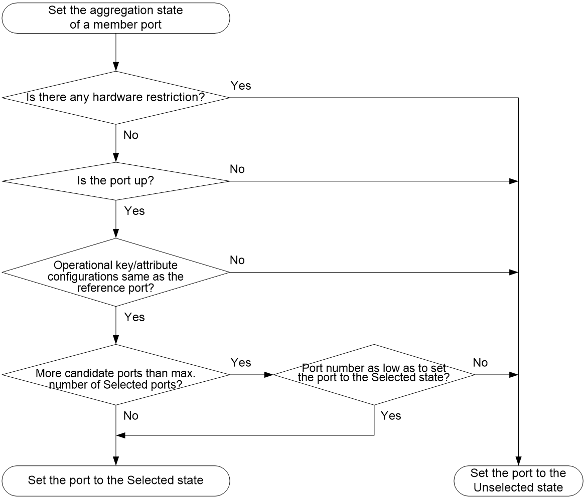
Aggregating links in dynamic mode
Dynamic aggregation is implemented through IEEE 802.3ad Link Aggregation Control Protocol (LACP).
LACP uses LACPDUs to exchange aggregation information between LACP-enabled devices.
Each member port in an LACP-enabled aggregation group exchanges information with its peer. When a member port receives an LACPDU, it compares the received information with information received on the other member ports. In this way, the two systems reach an agreement on which ports are placed in the Selected state.
The system chooses a reference port from the member ports that are in up state and have the same attribute settings as the aggregate interface. A Selected port must have the same operational key and attribute settings as the reference port.
The local system (the actor) and the peer system (the partner) negotiate a reference port by using the following workflow:
1. The two systems compare their system IDs to determine the system with the smaller system ID.
A system ID contains the system LACP priority and the system MAC address.
a. The two systems compare their LACP priority values.
The lower the LACP priority, the smaller the system ID. If LACP priority values are the same, the two systems proceed to the next step.
b. The two systems compare their MAC addresses.
The lower the MAC address, the smaller the system ID.
2. The system with the smaller system ID chooses the port with the smallest port ID as the reference port.
A port ID contains a port priority and a port number. The lower the port priority, the smaller the port ID.
a. The system chooses the port with the lowest priority value as the reference port.
If ports have the same priority, the system proceeds to the next step.
b. The system compares their port numbers.
The smaller the port number, the smaller the port ID.
The port with the smallest port number and the same attribute settings as the aggregate interface is chosen as the reference port.
After the reference port is chosen, the system with the smaller system ID sets the state of each member port on its side.
Figure 15 Setting the state of a member port in a dynamic aggregation group
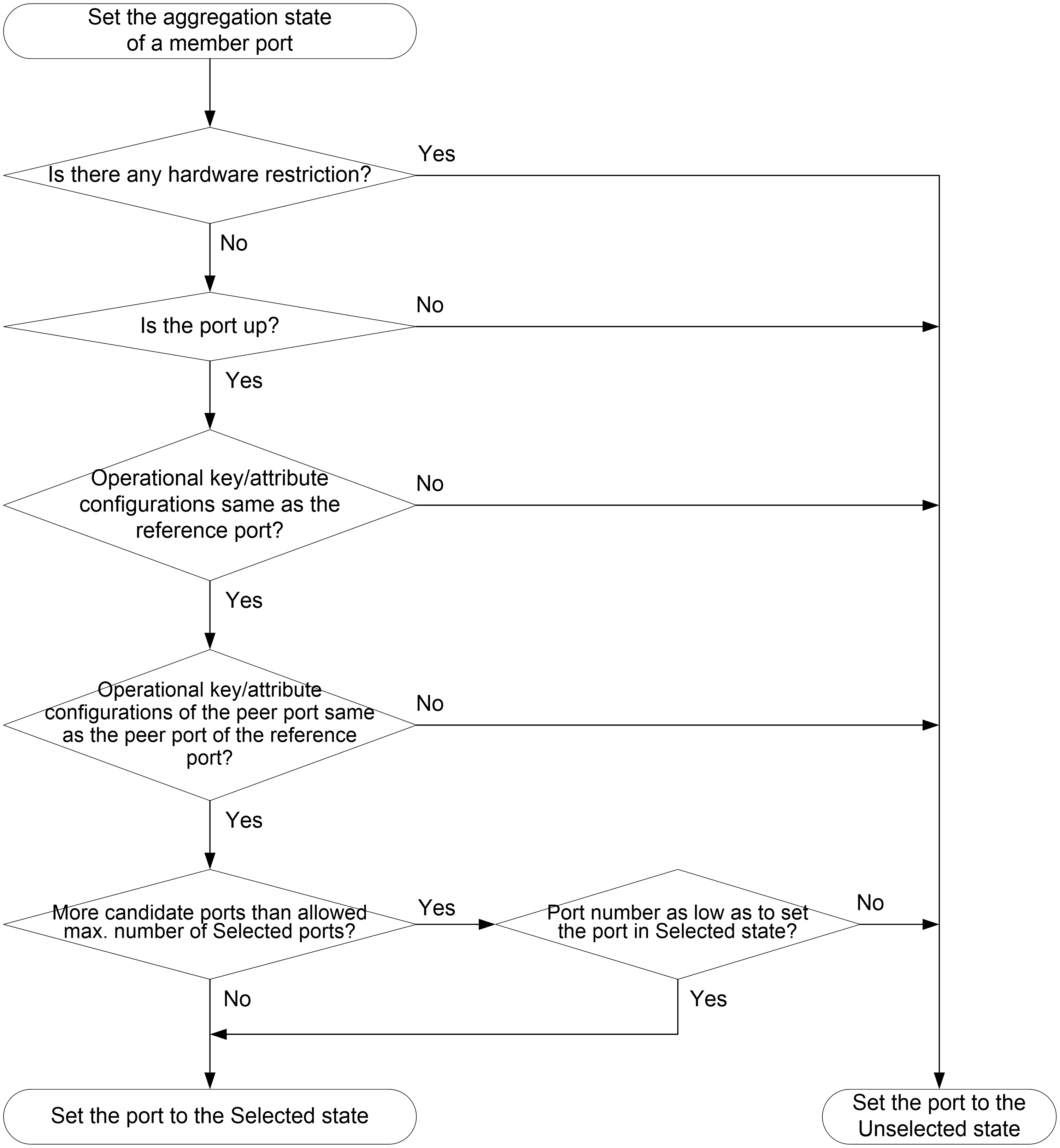
Meanwhile, the system with the higher system ID is aware of the aggregation state changes on the peer system. The system sets the aggregation state of local member ports the same as their peer ports.
PPPoE
About PPPoE
Point-to-Point Protocol over Ethernet (PPPoE) extends PPP by transporting PPP frames encapsulated in Ethernet over point-to-point links.
PPPoE specifies the methods for establishing PPPoE sessions and encapsulating PPP frames over Ethernet. PPPoE requires a point-to-point relationship between peers instead of a point-to-multipoint relationship as in multi-access environments such as Ethernet. PPPoE provides Internet access for the hosts in an Ethernet through a remote access device and implement access control, authentication, and accounting on a per-host basis. Integrating the low cost of Ethernet and scalability and management functions of PPP, PPPoE gained popularity in various application environments, such as residential access networks.
For more information about PPPoE, see RFC 2516.
PPPoE network structure
|
|
IMPORTANT: In the current software version, the device acts as the PPPoE client. |
PPPoE uses the client/server model. The PPPoE client initiates a connection request to the PPPoE server. After session negotiation between them is complete, a session is established between them, and the PPPoE server provides access control, authentication, and accounting to the PPPoE client.
As shown in Figure 16, the PPPoE session is established between devices (Device A and Device B). All hosts share one PPPoE session for data transmission without being installed with PPPoE client software. This network structure is typically used by enterprises.
Figure 16 PPPoE network structure
Links
VLAN
The Virtual Local Area Network (VLAN) technology breaks a LAN down into multiple logical LANs, which is called VLANs. Each VLAN is a broadcast domain. Hosts in the same VLAN can directly communicate with one another. Hosts in different VLANs are isolated from one another at Layer 2.
Port-based VLANs
Port-based VLANs group VLAN members by port. A port forwards packets from a VLAN only after it is assigned to the VLAN.
You can configure a port as an untagged or tagged port of a VLAN.
· To configure the port as an untagged port of a VLAN, assign it to the untagged port list of the VLAN. The untagged port of a VLAN forwards packets from the VLAN without VLAN tags.
· To configure the port as a tagged port of a VLAN, assign it to the tagged port list of the VLAN. The tagged port of a VLAN forwards packets from the VLAN with VLAN tags.
You can configure the link type of a port as access, trunk, or hybrid. Ports of different link types use different VLAN tag handling methods.
· Access—An access port can forward packets from only one VLAN and send them untagged. Assign an access port to only the untagged port list of a VLAN.
· Trunk—A trunk port can forward packets from multiple VLANs. Except packets from the port VLAN ID (PVID), packets sent out of a trunk port are VLAN-tagged. Assign a trunk port to the untagged port list of the PVID of the port, and to the tagged port lists of other VLANs.
· Hybrid—A hybrid port can forward packets from multiple VLANs. You can assign a hybrid port to the untagged port lists of some VLANs, and to the tagged port lists of other VLANs. An untagged hybrid port of a VLAN forwards packets from the VLAN without VLAN tags. A tagged hybrid port of a VLAN forwards packets from the VLAN with VLAN tags.
VLAN interface
For hosts of different VLANs to communicate at Layer 3, you can use VLAN interfaces. VLAN interfaces are virtual interfaces used for Layer 3 communication between different VLANs. They do not exist as physical entities on devices. For each VLAN, you can create one VLAN interface and assign an IP address to it. The VLAN interface acts as the gateway of the VLAN to forward packets destined for another IP subnet.
MAC
An Ethernet device uses a MAC address table to forward frames. A MAC address entry includes a destination MAC address, an outgoing interface (or egress RB), and a VLAN ID. When the device receives a frame, it uses the destination MAC address of the frame to look for a match in the MAC address table.
· The device forwards the frame out of the outgoing interface in the matching entry if a match is found.
· The device floods the frame in the VLAN of the frame if no match is found.
Types of MAC address entries
A MAC address table can contain the following types of entries:
· Dynamic entries—A dynamic entry can be manually configured or dynamically learned to forward frames with a specific destination MAC address out of the associated interface. A dynamic entry might age out. A manually configured dynamic entry has the same priority as a dynamically learned one.
· Static entries—A static entry is manually added to forward frames with a specific destination MAC address out of the associated interface, and it never ages out. A static entry has higher priority than a dynamically learned one.
· Blackhole entries—A blackhole entry is manually configured and never ages out. A blackhole entry is configured for filtering out frames with a specific source or destination MAC address. For example, to block all frames destined for or sourced from a user, you can configure the MAC address of the user as a blackhole MAC address entry. The blackhole entry of a MAC address has a higher priority than the dynamic entry of the MAC address.
Aging timer for dynamic MAC address entries
For security and efficient use of table space, the MAC address table uses an aging timer for dynamic entries learned on all interfaces. If a dynamic MAC address entry is not updated before the aging timer expires, the device deletes the entry. This aging mechanism ensures that the MAC address table can promptly update to accommodate latest network topology changes.
A stable network requires a longer aging interval, and an unstable network requires a shorter aging interval.
An aging interval that is too long might cause the MAC address table to retain outdated entries. As a result, the MAC address table resources might be exhausted, and the MAC address table might fail to update its entries to accommodate the latest network changes.
An interval that is too short might result in removal of valid entries, which would cause unnecessary floods and possibly affect the device performance.
To reduce floods on a stable network, set a long aging timer or disable the timer to prevent dynamic entries from unnecessarily aging out. Reducing floods improves the network performance. Reducing flooding also improves the security because it reduces the chances for a data frame to reach unintended destinations.
MAC address learning
MAC address learning is enabled by default. To prevent the MAC address table from being saturated when the device is experiencing attacks, disable MAC address learning. For example, you can disable MAC address learning to prevent the device from being attacked by a large amount of frames with different source MAC addresses.
When global MAC address learning is enabled, you can disable MAC address learning on a single interface.
You can also configure the MAC learning limit on an interface to limit the MAC address table size. A large MAC address table will degrade forwarding performance. When the limit is reached, the interface stops learning any MAC addresses. You can also configure whether to forward frames whose source MAC address is not in the MAC address table.
STP
Spanning tree protocols perform the following tasks:
· Prune the loop structure into a loop-free tree structure for a Layer 2 network by selectively blocking ports.
· Maintain the tree structure for the live network.
Spanning tree protocols include STP, RSTP, PVST, and MSTP.
· STP—Defined in IEEE 802.1d.
· RSTP—Defined in IEEE 802.1w. RSTP achieves rapid network convergence by allowing a newly elected root port or designated port to enter the forwarding state much faster than STP.
· PVST—PVST allows every VLAN to have its own spanning tree, which increases usage of links and bandwidth. Because each VLAN runs RSTP independently, a spanning tree only serves its VLAN.
· MSTP—Defined in IEEE 802.1s. MSTP overcomes the limitations of STP and RSTP. It supports rapid network convergence and allows data flows of different VLANs to be forwarded along separate paths. This provides a better load sharing mechanism for redundant links.
Spanning tree modes
The spanning tree modes include the following:
· STP mode—All ports of the device send STP BPDUs. Select this mode when the peer device of a port supports only STP.
· RSTP mode—All ports of the device send RSTP BPDUs. A port in this mode automatically transits to the STP mode when it receives STP BPDUs from a peer device. The port does not transit to the MSTP mode when it receives MSTP BPDUs from a peer device.
· PVST mode—On an access port, the PVST mode is compatible with other spanning tree modes in all VLANs. On a trunk port or hybrid port, the PVST mode is compatible with other spanning tree modes only in the default VLAN.
· MSTP mode—All ports of the device send MSTP BPDUs. A port in this mode automatically transits to the STP mode when it receives STP BPDUs from a peer device. The port does not transit to the RSTP mode when it receives RSTP BPDUs from a peer device.
MSTP basic concepts
MSTP divides a switched network into multiple spanning tree regions (MST regions). MSTP maintains multiple independent spanning trees in an MST region, and each spanning tree is mapped to specific VLANs. Such a spanning tree is referred to as a multiple spanning tree instance (MSTI). The common spanning tree (CST) is a single spanning tree that connects all MST regions in the switched network. An internal spanning tree (IST) is a spanning tree that runs in an MST region. It is also called MSTI 0, a special MSTI to which all VLANs are mapped by default. The common and internal spanning tree (CIST) is a single spanning tree that connects all devices in the switched network. It consists of the ISTs in all MST regions and the CST.
Devices in an MST region have the following characteristics:
· A spanning tree protocol enabled.
· Same region name.
· Same VLAN-to-instance mapping configuration.
· Same MSTP revision level.
· Physically linked together.
Port roles
Spanning tree calculation involves the following port roles:
· Root port—Forwards data for a non-root bridge to the root bridge. The root bridge does not have any root port.
· Designated port—Forwards data to the downstream network segment or device.
· Alternate port—Acts as the backup port for a root port or master port. When the root port or master port is blocked, the alternate port takes over.
· Backup port—Acts as the backup port of a designated port. When the designated port is invalid, the backup port becomes the new designated port. A loop occurs when two ports of the same spanning tree device are connected, so the device blocks one of the ports. The blocked port acts as the backup.
· Master port—Acts as a port on the shortest path from the local MST region to the common root bridge. The master port is not always located on the regional root. It is a root port on the IST or CIST and still a master port on the other MSTIs.
STP calculation involves root ports, designated ports, and alternate ports. RSTP calculation involves root ports, designated ports, alternate ports, and backup ports. MSTP calculation involves all port roles.
Port states
RSTP and MSTP define the following port states:
|
State |
Description |
|
Forwarding |
The port receives and sends BPDUs, and forwards user traffic. |
|
Learning |
The port receives and sends BPDUs, but does not forward user traffic. Learning is an intermediate port state. |
|
Discarding |
The port receives and sends BPDUs, but does not forward user traffic. |
STP defines the following port states: Disabled, Blocking, Listening, Learning, and Forwarding. The Disabled, Blocking, and Listening states correspond to the Discarding state in RSTP and MSTP.
Routing
Routing table
You can display routing table information, including brief routing table information and route statistics.
Static routing
Static routes are manually configured. If a network's topology is simple, you only need to configure static routes for the network to work correctly.
Static routes cannot adapt to network topology changes. If a fault or a topological change occurs in the network, the network administrator must modify the static routes manually.
A default route is used to forward packets that do not match any specific routing entry in the routing table. You can configure a default IPv4 route with destination address 0.0.0.0/0 and configure a default IPv6 route with destination address ::/0.
IP
NAT
Network Address Translation (NAT) translates an IP address in the IP packet header to another IP address. Typically, NAT is configured on gateways to enable private hosts to access external networks and external hosts to access private network resources such as a Web server.
Static NAT
Static NAT creates a fixed mapping between a private address and a public address. It supports connections initiated from internal users to the external network and from external users to the internal network. Static NAT applies to regular communications.
Dynamic NAT
Dynamic NAT uses an address pool to translate addresses. It applies to the scenario where a large number of internal users access the external network.
NO-PAT
Not Port Address Translation (NO-PAT) translates a private IP address to a public IP address by mapping the private IP address to the public IP address. The public IP address cannot be used by another internal host until it is released.
NO-PAT supports all IP packets and creates a NO-PAT entry for each IP address mapping.
PAT
Port Address Translation (PAT) translates multiple private IP addresses to a single public IP address by mapping the private IP addresses and source ports to the public IP address and a unique port.
PAT supports only TCP and UDP packets, and ICMP request packets.
NAT Server
The NAT Server feature maps a public address and port number to the private IP address and port number of an internal server. This feature allows servers in the private network to provide services for external users.
The following table describes the address-port mappings between an external network and an internal network for NAT Server.
Table 41 Address-port mappings for NAT Server
|
External network |
Internal network |
|
A public address |
A private address. |
|
A public address and a public port number |
A private address and a private port number. |
|
A public address and N consecutive public port numbers |
A private address and a private port number. |
|
N consecutive private addresses and a private port number. |
|
|
A private address and N consecutive private port numbers. |
|
|
N consecutive public addresses |
A private address. |
|
N consecutive private addresses. |
|
|
N consecutive public addresses and a public port number |
A private address and a private port number. |
|
N consecutive private addresses and a private port number. |
|
|
A private address and N consecutive private port numbers. |
|
|
A public address and a public port number |
A private server group. |
|
A public address and N consecutive public port numbers |
|
|
N consecutive public addresses and a public port number |
NAT 444
NAT444 provides carrier-grade NAT. It is a preferred solution for carriers to mitigate IPv4 address exhaustion. It introduces a second layer of NAT on the carrier side, with few changes on the customer side and the application server side. Its user logging function provides the user tracing service.
As shown in Figure 17, the NAT444 architecture includes the following entities:
· CPE—Provides NAT services on the customer side.
· BRAS—Provides Internet access services.
· NAT444 gateway—Provides carrier-grade NAT services.
· AAA server—Cooperates with BRAS to provide user authentication, authorization, and accounting services.
· Log server—Records user access logs and responds to queries for user access information.
Figure 17 NAT444 application diagram
The NAT444 gateway provides port block-based PAT translation. It maps multiple private IP addresses to one public IP address and uses a different port block for each private IP address.
For example, the private IP address 10.1.1.1 of an internal host is mapped to the public IP address 202.1.1.1 and port block 10001 to 10256. When the internal host accesses public hosts, the source IP address 10.1.1.1 is translated to 202.1.1.1, and the source ports are translated to ports in the port block 10001 to 10256.
NAT444 includes static NAT444 and dynamic NAT444.
· Static NAT444
The NAT444 gateway computes a static NAT444 mapping before address translation. The mapping is between a private IP address and a public IP address with a port block.
The NAT444 gateway uses private IP addresses, public IP addresses, a port range, and a port block size to compute static mappings:
a. Divides the port range by the port block size to get the number of available port blocks for each public IP address.
This value is the base number for mapping.
b. Sorts the port blocks in ascending order of the start port number in each block.
c. Sorts the private IP addresses and the public IP addresses separately in ascending order.
d. Maps the first base number of private IP addresses to the first public IP address and its port blocks in ascending order.
For example, the number of available port blocks of each public IP address is m. The first m private IP addresses are mapped to the first public IP address and the m port blocks in ascending order. The next m private IP addresses are mapped to the second IP address and the m port blocks in ascending order. The other static NAT444 mappings are created by analogy.
· Dynamic NAT444
Dynamic NAT444 works as follows:
a. Creates a mapping from the internal host's private IP address to a public IP address and a port block when the host initiates a connection to the public network.
b. Translates the private IP address to the public IP address, and the source ports to ports in the selected port block for subsequent connections from the private IP address.
c. Withdraws the port block and deletes the dynamic NAT444 mapping when all connections from the private IP address are disconnected.
Dynamic NAT444 uses ACLs to implement translation control. It processes only packets that match an ACL permit rule.
Dynamic NAT444 supports port block extending. If the ports in the port block for a private address are all occupied, dynamic NAT444 translates the source port to a port in an extended port block.
Advanced settings
NAT address group
A NAT address group is a set of address ranges. Dynamic NAT uses a NAT address group to translate a larger group of private IP addresses.
NAT444 address group
A NAT444 address group is used to perform dynamic NAT444. A NAT444 address group is similar to a NAT address group. The difference is that a NAT444 address group includes port block parameters, such as a port range, a port block size, and an extended port block number.
Port block group
A port block group is used to perform static NAT444. A port block group includes private IP addresses, public IP addresses, a port range, and a port block size. The NAT444 gateway uses these parameters to calculate static NAT444 mappings and performs NAT444 accordingly.
Internal server group
An internal server group is used to configure load-sharing NAT Server. The internal servers in the group provide the same service to external hosts. When an external host sends a request to the pubic IP address mapped to the internal server group, the NAT device chooses an internal server based on the weight and number of connections of the servers.
PAT
PAT supports the following mappings:
· Endpoint-Independent Mapping—Uses the same IP and port mapping (EIM entry) for packets from the same source IP and port to any destination. EIM allows external hosts to access the internal hosts by using the translated IP address and port. It allows internal hosts behind different NAT gateways to access each other.
· Address and Port-Dependent Mapping—Uses different IP and port mappings for packets from the same source IP and port to different destination IP addresses and ports. APDM allows an external host to access an internal host only under the condition that the internal host has previously accessed the external host. It is secure, but it does not allow internal hosts behind different NAT gateways to access each other.
NAT with DNS mapping
NAT with DNS mapping allows an internal host to access an internal server on the same private network by using the domain name of the internal server when the DNS server is on the public network.
NAT with DNS mapping must operate with NAT Server. DNS mapping maps the domain name to the public IP address, public port number, and protocol type of the internal server. NAT Server maps the public IP and port to the private IP and port of the internal server.
DNS mapping can also be used by DNS ALG. The DNS reply from the external DNS server contains only the domain name and public IP address of the internal server in the payload. The NAT interface might have multiple internal servers configured with the same public IP address but different private IP addresses. DNS ALG might find an incorrect internal server by using only the public IP address. If a DNS mapping is configured, DNS ALG can obtain the public IP address, public port number, and protocol type of the internal server by using the domain name. Then it can find the correct internal server by using the public IP address, public port number, and protocol type of the internal server.
NAT hairpin
NAT hairpin allows internal hosts to access each other through NAT.
NAT hairpin includes P2P and C/S modes:
· P2P—Allows internal hosts to access each other through NAT.
To configure the P2P mode, you must configure outbound PAT on the interface connected to the external network and enable the EIM mapping mode. Internal hosts first register their public addresses to an external server. Then, the hosts communicate with each other by using the registered IP addresses.
· C/S—Allows internal hosts to access internal servers through NAT.
In C/S mode, the source and destination IP address of a packet are translated on the interface connected to the internal network. The destination IP address of the packet going to the internal server is translated by matching the NAT Server configuration. The source IP address is translated by matching the outbound dynamic or static NAT entries.
NAT hairpin typically operates with NAT Server, outbound dynamic NAT, or outbound static NAT. They must be configured on interfaces of the same interface card. Otherwise, NAT hairpin cannot function correctly.
NAT with ALG
NAT with ALG translates address or port information in the application layer payloads to ensure connection establishment.
NAT logging
· NAT session logging
NAT session logging records NAT session information, including translation information, access information, and flow information.
A NAT device generates NAT session logs for the following events:
¡ NAT session establishment.
¡ NAT session removal. This event occurs when you add a configuration with a higher priority, remove a configuration, and change ACLs, when a NAT session ages out, or when you manually delete a NAT session.
¡ Active NAT session logging.
· NAT444 user logging
NAT444 user logs are used for user tracing. The NAT444 gateway generates a user log whenever it assigns or withdraws a port block. The log includes the private IP address, public IP address, and port block. You can use the public IP address and port numbers to locate the user's private IP address from the user logs.
A NAT444 gateway generates NAT user logs when one of the following events occurs:
¡ A port block is assigned.
For static NAT444, the NAT444 gateway generates a user log when it translates the first connection from a private IP address.
For dynamic NAT444, the NAT444 gateway generates a user log when it assigns or extends a port block for a private IP address.
¡ A port block is withdrawn.
For static NAT444, the NAT444 gateway generates a user log when all connections from a private IP address are disconnected.
For dynamic NAT444, the NAT444 gateway generates a user log when all the following conditions are met:
- All connections from a private IP address are disconnected.
- The port blocks (including the extended ones) assigned to the private IP address are withdrawn.
- The corresponding mapping entry is deleted.
· NAT444 alarm logging
If the public IP addresses, port blocks, or ports in selected port blocks (including extended ones) are all occupied, the NAT444 gateway cannot perform address translation and packets will be dropped. To monitor the usage of public IP addresses and port block resources, you can configure NAT444 alarm logging.
A NAT444 gateway generates alarm logs when one of the following occurs:
¡ The ports in the selected port block of a static NAT444 mapping are all occupied.
¡ The ports in the selected port blocks (including extended ones) of a dynamic NAT444 mapping are all occupied.
¡ The public IP addresses and port blocks for dynamic NAT444 are all assigned.
Restrictions and guidelines
When you configure NAT, follow these restrictions and guidelines:
· Do not configure inbound static NAT alone. Typically, inbound static NAT functions with outbound dynamic NAT, NAT Server, or outbound static NAT to implement bidirectional NAT.
· The following shows the priorities of different NAT features in descending order:
¡ NAT Server.
¡ Static NAT.
¡ Static NAT444.
¡ Dynamic NAT and dynamic NAT444.
Dynamic NAT and dynamic NAT444 have the same priority. They are matched in the descending order of ACL numbers.
· The address ranges in a NAT address group cannot overlap with each other.
· The number of IP addresses in a NAT address group cannot be smaller than the number of security engines.
· In an internal server group, an internal server with a larger weight provides a larger percentage of service.
· Before configuring NAT444 user and alarm logging, you must configure the custom NAT444 log generation and outputting functions.
IP
IP address classes
IP addressing uses a 32-bit address to identify each host on an IPv4 network. To make addresses easier to read, they are written in dotted decimal notation, each address being four octets in length. For example, address 00001010000000010000000100000001 in binary is written as 10.1.1.1.
Each IP address breaks down into the following sections:
· Net ID—Identifies a network. The first several bits of a net ID, known as the class field or class bits, identify the class of the IP address.
· Host ID—Identifies a host on a network.
IP addresses are divided into five classes. The following table shows IP address classes and ranges. The first three classes are most commonly used.
|
Class |
Address range |
Remarks |
|
A |
0.0.0.0 to 127.255.255.255 |
The IP address 0.0.0.0 is used by a host at startup for temporary communication. This address is never a valid destination address. Addresses starting with 127 are reserved for loopback test. Packets destined to these addresses are processed locally as input packets rather than sent to the link. |
|
B |
128.0.0.0 to 191.255.255.255 |
N/A |
|
C |
192.0.0.0 to 223.255.255.255 |
N/A |
|
D |
224.0.0.0 to 239.255.255.255 |
Multicast addresses. |
|
E |
240.0.0.0 to 255.255.255.255 |
Reserved for future use, except for the broadcast address 255.255.255.255. |
Subnetting and masking
Subnetting divides a network into smaller networks called subnets by using some bits of the host ID to create a subnet ID.
Masking identifies the boundary between the host ID and the combination of net ID and subnet ID.
Each subnet mask contains 32 bits that correspond to the bits in an IP address. In a subnet mask, consecutive ones represent the net ID and subnet ID, and consecutive zeros represent the host ID.
Before being subnetted, Class A, B, and C networks use these default masks (also called natural masks): 255.0.0.0, 255.255.0.0, and 255.255.255.0, respectively.
Subnetting increases the number of addresses that cannot be assigned to hosts. Therefore, using subnets means accommodating fewer hosts.
For example, a Class B network without subnetting can accommodate 1022 more hosts than the same network subnetted into 512 subnets.
· Without subnetting—65534 (216 – 2) hosts. (The two deducted addresses are the broadcast address, which has an all-one host ID, and the network address, which has an all-zero host ID.)
· With subnetting—Using the first nine bits of the host-id for subnetting provides 512 (29) subnets. However, only seven bits remain available for the host ID. This allows 126 (27 – 2) hosts in each subnet, a total of 64512 (512 × 126) hosts.
IP address configuration methods
You can use the following methods to enable an interface to obtain an IP address:
· Manually assign an IP address to the interface.
· Configure the interface to obtain an IP address through DHCP.
MTU for an interface
When a packet exceeds the MTU of the output interface, the device processes the packet in one of the following ways:
· If the packet disallows fragmentation, the device discards it.
· If the packet allows fragmentation, the device fragments it and forwards the fragments.
Fragmentation and reassembling consume system resources, so set an appropriate MTU for an interface based on the network environment to avoid fragmentation.
ARP
ARP resolves IP addresses into MAC addresses on Ethernet networks.
Types of ARP table entries
An ARP table stores dynamic and static ARP entries.
Dynamic ARP entry
ARP automatically creates and updates dynamic entries. A dynamic ARP entry is removed when its aging timer expires or when the output interface goes down. In addition, a dynamic ARP entry can be overwritten by a static ARP entry.
Dynamic ARP entries can be converted to static ARP entries. These static ARP entries cannot be converted back to dynamic entries.
To prevent an interface from holding too many ARP entries, you can set the maximum number of dynamic ARP entries that the interface can learn.
Static ARP entry
A static ARP entry is manually configured or converted from a dynamic ARP entry. It does not age out and cannot be overwritten by any dynamic ARP entry.
Static ARP entries protect communication between devices because attack packets cannot modify the IP-to-MAC mapping in a static ARP entry.
To communicate with a host by using a fixed IP-to-MAC mapping, configure a static ARP entry on the device.
To communicate with a host by using a fixed IP-to-MAC mapping through an interface in a VLAN, you must specify the VLAN and the output interface in the ARP entry. Make sure the IP address is on the same subnet as the IP address of the VLAN interface.
Proxy ARP
Proxy ARP enables a device on one network to answer ARP requests for an IP address on another network. With proxy ARP, hosts on different broadcast domains can communicate with each other as they would on the same broadcast domain.
Proxy ARP includes common proxy ARP and local proxy ARP.
· Common proxy ARP—Allows communication between hosts that connect to different Layer 3 interfaces and reside in different broadcast domains.
· Local proxy ARP—Allows communication between hosts that connect to the same Layer 3 interface and reside in different broadcast domains.
You can specify an IP address range for which local proxy ARP is enabled.
Gratuitous ARP
In a gratuitous ARP packet, the sender IP address and the target IP address are the IP address of the sending device.
A device sends a gratuitous ARP packet for either of the following purposes:
· Determine whether its IP address is already used by another device. If the IP address is already used, the device is informed of the conflict by an ARP reply.
· Inform other devices of a MAC address change.
Gratuitous ARP packet learning
This function enables a device to create or update ARP entries by using the sender IP and MAC addresses in received gratuitous ARP packets.
When this function is disabled, the device uses received gratuitous ARP packets to update existing ARP entries only. ARP entries are not created based on the received gratuitous ARP packets, which saves ARP table space.
Replying with gratuitous ARP packets
This function enables a device to send gratuitous ARP packets upon receiving ARP requests whose sender IP address is on a different subnet.
Periodic sending of gratuitous ARP packets
Enabling periodic sending of gratuitous ARP packets helps downstream devices update ARP entries or MAC entries in a timely manner.
This feature can implement the following functions:
· Prevent gateway spoofing.
Gateway spoofing occurs when an attacker uses the gateway address to send gratuitous ARP packets to the hosts on a network. The traffic destined for the gateway from the hosts is sent to the attacker instead. As a result, the hosts cannot access the external network.
To prevent such gateway spoofing attacks, you can enable the gateway to send gratuitous ARP packets at intervals. Gratuitous ARP packets contain the primary IP address and manually configured secondary IP addresses of the gateway, so hosts can learn correct gateway information.
· Prevent ARP entries from aging out.
If network traffic is heavy or if the host CPU usage is high, received ARP packets can be discarded or are not promptly processed. Eventually, the dynamic ARP entries on the receiving host age out. The traffic between the host and the corresponding devices is interrupted until the host re-creates the ARP entries.
To prevent this problem, you can enable the gateway to send gratuitous ARP packets periodically. Gratuitous ARP packets contain the primary IP address and manually configured secondary IP addresses of the gateway, so the receiving hosts can update ARP entries in a timely manner.
ARP attack protection
ARP attacks and viruses are threatening LAN security. Although ARP is easy to implement, it provides no security mechanism and is vulnerable to network attacks. Multiple features are used to detect and prevent ARP attacks.
· The gateway supports the following features:
¡ ARP blackhole routing.
¡ ARP source suppression.
¡ ARP packet source MAC consistency check.
¡ ARP active acknowledgement.
¡ Source MAC-based ARP attack detection.
¡ Authorized ARP.
¡ ARP scanning and fixed ARP.
· The access device supports the following features:
¡ ARP gateway protection.
¡ ARP filtering.
¡ ARP detection.
Unresolvable IP attack protection
If a device receives a large number of unresolvable IP packets from a host, the following situations can occur:
· The device sends a large number of ARP requests, overloading the target subnets.
· The device keeps trying to resolve the destination IP addresses, overloading its CPU.
To protect the device from such IP attacks, you can configure the following features:
· ARP source suppression—Stops resolving packets from a host if the number of unresolvable IP packets from the host exceeds the upper limit within 5 seconds. The device continues ARP resolution when the interval elapses. This feature is applicable if the attack packets have the same source addresses.
· ARP blackhole routing—Creates a blackhole route destined for an unresolvable IP address. The device drops all matching packets until the blackhole route ages out. This feature is applicable regardless of whether the attack packets have the same source addresses.
ARP packet source MAC consistency check
This feature enables a gateway to filter out ARP packets whose source MAC address in the Ethernet header is different from the sender MAC address in the message body. This feature allows the gateway to learn correct ARP entries.
ARP active acknowledgement
Configure this feature on gateways to prevent user spoofing.
ARP active acknowledgement prevents a gateway from generating incorrect ARP entries.
In strict mode, a gateway performs more strict validity checks before creating an ARP entry:
· Upon receiving an ARP request destined for the gateway, the gateway sends an ARP reply but does not create an ARP entry.
· Upon receiving an ARP reply, the gateway determines whether it has resolved the sender IP address:
¡ If yes, the gateway performs active acknowledgement. When the ARP reply is verified as valid, the gateway creates an ARP entry.
¡ If not, the gateway discards the packet.
Source MAC-based ARP attack detection
This feature checks the number of ARP packets delivered to the CPU. If the number of packets from the same MAC address within 5 seconds exceeds a threshold, the device adds the MAC address to an ARP attack entry. Before the entry is aged out, the device handles the attack by using either of the following methods:
· Monitor—Only generates log messages.
· Filter—Generates log messages and filters out subsequent ARP packets from that MAC address.
You can exclude the MAC addresses of some gateways and servers from this detection. This feature does not inspect ARP packets from those devices even if they are attackers.
Authorized ARP
Authorized ARP entries are generated based on the DHCP clients' address leases on the DHCP server or dynamic client entries on the DHCP relay agent.
With authorized ARP enabled, an interface is disabled from learning dynamic ARP entries. This feature prevents user spoofing and allows only authorized clients to access network resources.
ARP scanning and fixed ARP
ARP scanning is typically used together with the fixed ARP feature in small-scale networks.
ARP scanning automatically creates ARP entries for devices in an address range. The device performs ARP scanning by using the following steps:
1. Sends ARP requests for each IP address in the address range.
2. Obtains their MAC addresses through received ARP replies.
3. Creates dynamic ARP entries.
Fixed ARP converts existing dynamic ARP entries (including those generated through ARP scanning) to static ARP entries. This feature prevents ARP entries from being modified by attackers.
ARP packet rate limit
The ARP packet rate limit feature allows you to limit the rate of ARP packets delivered to the CPU. An ARP detection enabled device will send all received ARP packets to the CPU for inspection. Processing excessive ARP packets will make the device malfunction or even crash. To resolve this issue, configure ARP packet rate limit.
Configure this feature when ARP detection is enabled or when ARP flood attacks are detected.
If logging for ARP packet rate limit is enabled, the device sends the highest threshold-crossed ARP packet rate within the sending interval in a log message to the information center. You can configure the information center module to set the log output rules.
ARP detection
ARP detection enables access devices to block ARP packets from unauthorized clients to prevent user spoofing and gateway spoofing attacks. ARP detection does not check ARP packets received from ARP trusted ports.
ARP detection provides the following functions:
· User validity check
If you only enable ARP detection for a VLAN, ARP detection provides only the user validity check.
Upon receiving an ARP packet from an ARP untrusted interface, the device matches the sender IP and MAC addresses with the following entries:
¡ Static IP source guard binding entries.
¡ DHCP snooping entries.
If a match is found, the ARP packet is considered valid and is forwarded. If no match is found, the ARP packet is considered invalid and is discarded.
· ARP packet validity check
Enable validity check for ARP packets received on untrusted ports and specify the following objects to be checked:
¡ Sender MAC—Checks whether the sender MAC address in the message body is identical to the source MAC address in the Ethernet header. If they are identical, the packet is forwarded. Otherwise, the packet is discarded.
¡ Target MAC—Checks the target MAC address of ARP replies. If the target MAC address is all-zero, all-one, or inconsistent with the destination MAC address in the Ethernet header, the packet is considered invalid and discarded.
¡ IP—Checks the sender and target IP addresses of ARP replies, and the sender IP address of ARP requests. All-one or multicast IP addresses are considered invalid and the corresponding packets are discarded.
· ARP restricted forwarding
ARP restricted forwarding controls the forwarding of ARP packets that are received on untrusted interfaces and have passed user validity check as follows:
¡ If the packets are ARP requests, they are forwarded through the trusted interface.
¡ If the packets are ARP replies, they are forwarded according to their destination MAC address. If no match is found in the MAC address table, they are forwarded through the trusted interface.
IPv4 DNS
Domain Name System (DNS) is a distributed database used by TCP/IP applications to translate domain names into IP addresses. IPv4 DNS translates domain names into IPv4 addresses. IPv6 DNS translates domain names into IPv6 addresses. The domain name-to-IP address mapping is called a DNS entry.
Dynamic domain name resolution
To use dynamic domain name resolution, you must specify a DNS server address for a device. The device sends DNS queries to the DNS server for domain name resolution.
You can configure a domain name suffix list so that the resolver can use the list to supply the missing part of an incomplete name. For example, you can configure com as the suffix for aabbcc.com. The user only needs to enter aabbcc to obtain the IP address of aabbcc.com. The resolver adds the suffix and delimiter before passing the name to the DNS server.
The name resolver handles the queries based on the domain names that the user enters:
· If the user enters a domain name without a dot (.) (for example, aabbcc), the resolver considers the domain name as a host name. It adds a DNS suffix to the host name before performing the query operation. If no match is found for any host name and suffix combination, the resolver uses the user-entered domain name (for example, aabbcc) for the IP address query.
· If the user enters a domain name with a dot (.) among the letters (for example, www.aabbcc), the resolver directly uses this domain name for the query operation. If the query fails, the resolver adds a DNS suffix for another query operation.
· If the user enters a domain name with a dot (.) at the end (for example, aabbcc.com.), the resolver considers the domain name an FQDN and returns the successful or failed query result. The dot at the end of the domain name is considered a terminating symbol.
Static domain name resolution
Static domain name resolution means manually creating mappings between domain names and IP addresses. For example, you can create a static DNS mapping for a device so that you can Telnet to the device by using the domain name.
After a user specifies a name, the device checks the static name resolution table for an IP address. If no IP address is available, it contacts the DNS server for dynamic name resolution, which takes more time than static name resolution. To improve efficiency, you can put frequently queried name-to-IP address mappings in the local static name resolution table.
DNS proxy
The DNS proxy performs the following tasks:
· Forwards the request from the DNS client to the designated DNS server.
· Conveys the reply from the DNS server to the client.
The DNS proxy simplifies network management. When the DNS server address is changed, you can change the configuration on only the DNS proxy instead of on each DNS client.
IPv6
IPv6
IPv6, also called IP next generation (IPng), was designed by the IETF as the successor to IPv4. One significant difference between IPv6 and IPv4 is that IPv6 increases the IP address size from 32 bits to 128 bits.
IPv6 address formats
An IPv6 address is represented as a set of 16-bit hexadecimals separated by colons (:). An IPv6 address is divided into eight groups, and each 16-bit group is represented by four hexadecimal numbers, for example, 2001:0000:130F:0000:0000:09C0:876A:130B.
To simplify the representation of IPv6 addresses, you can handle zeros in IPv6 addresses by using the following methods:
· The leading zeros in each group can be removed. For example, the above address can be represented in a shorter format as 2001:0:130F:0:0:9C0:876A:130B.
· If an IPv6 address contains one or more consecutive groups of zeros, they can be replaced by a double colon (::). For example, the above address can be represented in the shortest format as 2001:0:130F::9C0:876A:130B.
An IPv6 address consists of an address prefix and an interface ID, which are equivalent to the network ID and the host ID of an IPv4 address.
An IPv6 address prefix is written in IPv6-address/prefix-length notation. The prefix-length is a decimal number indicating how many leftmost bits of the IPv6 address are in the address prefix.
IPv6 address types
IPv6 addresses include the following types:
· Unicast address—An identifier for a single interface, similar to an IPv4 unicast address. A packet sent to a unicast address is delivered to the interface identified by that address.
· Multicast address—An identifier for a set of interfaces (typically belonging to different nodes), similar to an IPv4 multicast address. A packet sent to a multicast address is delivered to all interfaces identified by that address.
· Broadcast addresses are replaced by multicast addresses in IPv6.
· Anycast address—An identifier for a set of interfaces (typically belonging to different nodes). A packet sent to an anycast address is delivered to the nearest interface among the interfaces identified by that address. The nearest interface is chosen according to the routing protocol's measure of distance.
The type of an IPv6 address is designated by the first several bits, called the format prefix. The following table shows mappings between address types and format prefixes:
|
Type |
Format prefix (binary) |
IPv6 prefix ID |
Remarks |
|
|
Unicast address |
Unspecified address |
00...0 (128 bits) |
::/128 |
It cannot be assigned to any node. Before acquiring a valid IPv6 address, a node fills this address in the source address field of IPv6 packets. The unspecified address cannot be used as a destination IPv6 address. |
|
Loopback address |
00...1 (128 bits) |
::1/128 |
It has the same function as the loopback address in IPv4. It cannot be assigned to any physical interface. A node uses this address to send an IPv6 packet to itself. |
|
|
Link-local address |
1111111010 |
FE80::/10 |
Used for communication among link-local nodes for neighbor discovery and stateless autoconfiguration. Packets with link-local source or destination addresses are not forwarded to other links. |
|
|
Global unicast address |
Other forms |
N/A |
Equivalent to public IPv4 addresses, global unicast addresses are provided for Internet service providers. This type of address allows for prefix aggregation to restrict the number of global routing entries. |
|
|
Multicast address |
11111111 |
FF00::/8 |
N/A |
|
|
Anycast address |
Anycast addresses use the unicast address space and have the identical structure of unicast addresses. |
N/A |
||
EUI-64 address-based interface identifiers
An interface identifier is 64-bit long and uniquely identifies an interface on a link. Interfaces generate EUI-64 address-based interface identifiers differently.
· On an IEEE 802 interface (such as an Ethernet interface and a VLAN interface)—The interface identifier is derived from the link-layer address (typically a MAC address) of the interface. The MAC address is 48-bit long.
To obtain an EUI-64 address-based interface identifier, follow these steps:
a. Insert the 16-bit binary number 1111111111111110 (hexadecimal value of FFFE) behind the 24th high-order bit of the MAC address.
b. Invert the universal/local (U/L) bit (the seventh high-order bit). This operation makes the interface identifier have the same local or global significance as the MAC address.
· On a tunnel interface—The lower 32 bits of the EUI-64 address-based interface identifier are the source IPv4 address of the tunnel interface. The higher 32 bits of the EUI-64 address-based interface identifier of an ISATAP tunnel interface are 0000:5EFE, whereas those of other tunnel interfaces are all zeros.
· On an interface of another type—The EUI-64 address-based interface identifier is generated randomly by the device.
IPv6 global unicast address configuration methods
Use one of the following methods to configure an IPv6 global unicast address for an interface:
· EUI-64 IPv6 address—The IPv6 address prefix of the interface is manually configured, and the interface identifier is generated automatically by the interface.
· Manual configuration—The IPv6 global unicast address is manually configured.
· Stateless address autoconfiguration—The IPv6 global unicast address is generated automatically according to the address prefix information contained in the RA message and the EUI-64 address-based interface identifier.
· Stateful address autoconfiguration—Enables a host to acquire an IPv6 address from a DHCPv6 server.
You can configure multiple IPv6 global unicast addresses on an interface.
IPv6 link-local address configuration methods
Configure IPv6 link-local addresses by using one of the following methods for an interface:
· Automatic generation—The device automatically generates a link-local address for an interface according to the link-local address prefix (FE80::/10) and the EUI-64 address-based interface identifier.
· Manual assignment—An IPv6 link-local address is manually configured.
An interface can have only one link-local address. As a best practice to avoid link-local address conflicts, use the automatic generation method. If both methods are used, manual assignment takes precedence over automatic generation.
· If you first use automatic generation and then manual assignment, the manually assigned link-local address overwrites the automatically generated one.
· If you first use manual assignment and then automatic generation, both of the following occur:
¡ The link-local address is still the manually assigned one.
¡ The automatically generated link-local address does not take effect. If you delete the manually assigned address, the automatically generated link-local address takes effect.
ND
The IPv6 Neighbor Discovery (ND) protocol uses ICMPv6 messages to provide the following functions:
· Address resolution
· Neighbor reachability detection
· DAD
· Router/prefix discovery
· Stateless address autoconfiguration
· Redirection
Table 42 describes the ICMPv6 messages used by ND.
Table 42 ICMPv6 messages used by ND
|
ICMPv6 message |
Type |
Function |
|
Neighbor Solicitation (NS) |
135 |
Acquires the link-layer address of a neighbor. |
|
Verifies whether a neighbor is reachable. |
||
|
Detects duplicate addresses. |
||
|
Neighbor Advertisement (NA) |
136 |
Responds to an NS message. |
|
Notifies the neighboring nodes of link layer changes. |
||
|
Router Solicitation (RS) |
133 |
Requests an address prefix and other configuration information for autoconfiguration after startup. |
|
Router Advertisement (RA) |
134 |
Responds to an RS message. |
|
Advertises information, such as the Prefix Information options and flag bits. |
||
|
Redirect |
137 |
Informs the source host of a better next hop on the path to a particular destination when certain conditions are met. |
Neighbor entries
A neighbor entry stores information about a neighboring node on the link. Neighbor entries can be dynamically configured through NS and NA messages or manually configured.
You can configure a static neighbor entry by using one of the following methods:
· Method 1—Associate a neighbor's IPv6 address and link-layer address with the local Layer 3 interface.
If you use Method 1, the device automatically finds the Layer 2 port connected to the neighbor.
· Method 2—Associate a neighbor's IPv6 address and link-layer address with a Layer 2 port in a VLAN.
If you use Method 2, make sure the corresponding VLAN interface exists and the Layer 2 port belongs to the VLAN.
RA messages
An RA message is advertised by a router to all hosts on the same link. The RA message contains the address prefix and other configuration information for the hosts to generate IPv6 addresses through stateless address autoconfiguration.
You can enable an interface to send RA messages, specify the maximum and minimum sending intervals and configure parameters in RA messages. The device sends RA messages at random intervals between the maximum and minimum intervals. The minimum interval must be less than or equal to 0.75 times the maximum interval.
Table 43 describes the configurable parameters in an RA message.
Table 43 Parameters in an RA message and their descriptions
|
Parameter |
Description |
|
IPv6 prefix/prefix length |
The IPv6 prefix/prefix length for a host to generate an IPv6 global unicast address through stateless autoconfiguration. |
|
Valid lifetime |
Specifies the valid lifetime of a prefix. The generated IPv6 address is valid within the valid lifetime and becomes invalid when the valid lifetime expires. |
|
Preferred lifetime |
Specifies the preferred lifetime of a prefix used for stateless autoconfiguration. After the preferred lifetime expires, the node cannot use the generated IPv6 address to establish new connections, but can receive packets destined for the IPv6 address. The preferred lifetime cannot be greater than the valid lifetime. |
|
No-autoconfig flag |
Notifies the hosts to not use the address prefix for stateless autoconfiguration. |
|
Off-link flag |
Specifies the address with the prefix to be indirectly reachable on the link. |
|
MTU |
Guarantees that all nodes on the link use the same MTU. |
|
Unlimited hops flag |
Specifies unlimited hops in RA messages. |
|
M flag |
Determines whether a host uses stateful autoconfiguration to obtain an IPv6 address. If the M flag is set, the host uses stateful autoconfiguration (for example, from a DHCPv6 server) to obtain an IPv6 address. If the flag is not set, the host uses stateless autoconfiguration to generate an IPv6 address according to its link-layer address and the prefix information in the RA message. |
|
O flag |
Determines whether a host uses stateful autoconfiguration to obtain configuration information other than IPv6 address. If the O flag is set, the host uses stateful autoconfiguration (for example, from a DHCPv6 server) to obtain configuration information other than IPv6 address. If the flag is not set, the host uses stateless autoconfiguration. |
|
Router Lifetime |
Advertises the lifetime of an advertising router. If the lifetime is 0, the router cannot be used as the default gateway. |
|
Retrans Timer |
Specifies the interval for retransmitting the NS message after the device does not receive a response for an NS message within a time period. |
|
Router Preference |
Specifies the router preference in an RA message. A host selects a router as the default gateway according to the router preference. If router preferences are the same, the host selects the router from which the first RA message is received. |
|
Reachable Time |
Specifies the reachable period for a neighbor after the device detects that a neighbor is reachable. If the device needs to send a packet to the neighbor after the reachable period, the device reconfirms whether the neighbor is reachable. |
ND proxy
ND proxy enables a device to answer an NS message requesting the hardware address of a host on another network. With ND proxy, hosts in different broadcast domains can communicate with each other as they would on the same network.
ND proxy includes common ND proxy and local ND proxy.
Common ND proxy
As shown in Figure 18, Interface A with IPv6 address 4:1::96/64 and Interface B with IPv6 address 4:2::99/64 belong to different subnets. Host A and Host reside on the same network but in different broadcast domains.
Figure 18 Application environment of common ND proxy

Because Host A's IPv6 address is on the same subnet as Host B's, Host A directly sends an NS message to obtain Host B's MAC address. However, Host B cannot receive the NS message because they belong to different broadcast domains.
To solve this problem, enable common ND proxy on Interface A and Interface B of the Device. The Device replies to the NS message from Host A, and forwards packets from other hosts to Host B.
Local ND proxy
As shown in Figure 19, Host A belongs to VLAN 2 and Host B belongs to VLAN 3. Host A and Host B connect to Interface A and Interface C, respectively.
Figure 19 Application environment of local ND proxy
Because Host A's IPv6 address is on the same subnet as Host B's, Host A directly sends an NS message to obtain Host B's MAC address. However, Host B cannot receive the NS message because they are in different VLANs.
To solve this problem, enable local ND proxy on Interface B of the router so that the router can forward messages between Host A and Host B.
IPv6 DNS
Domain Name System (DNS) is a distributed database used by TCP/IP applications to translate domain names into IP addresses. IPv4 DNS translates domain names into IPv4 addresses. IPv6 DNS translates domain names into IPv6 addresses. The domain name-to-IP address mapping is called a DNS entry.
Dynamic domain name resolution
To use dynamic domain name resolution, you must specify a DNS server address for a device. The device sends DNS queries to the DNS server for domain name resolution.
You can configure a domain name suffix list so that the resolver can use the list to supply the missing part of an incomplete name. For example, you can configure com as the suffix for aabbcc.com. The user only needs to enter aabbcc to obtain the IP address of aabbcc.com. The resolver adds the suffix and delimiter before passing the name to the DNS server.
The name resolver handles the queries based on the domain names that the user enters:
· If the user enters a domain name without a dot (.) (for example, aabbcc), the resolver considers the domain name as a host name. It adds a DNS suffix to the host name before performing the query operation. If no match is found for any host name and suffix combination, the resolver uses the user-entered domain name (for example, aabbcc) for the IP address query.
· If the user enters a domain name with a dot (.) among the letters (for example, www.aabbcc), the resolver directly uses this domain name for the query operation. If the query fails, the resolver adds a DNS suffix for another query operation.
· If the user enters a domain name with a dot (.) at the end (for example, aabbcc.com.), the resolver considers the domain name an FQDN and returns the successful or failed query result. The dot at the end of the domain name is considered a terminating symbol.
Static domain name resolution
Static domain name resolution means manually creating mappings between domain names and IP addresses. For example, you can create a static DNS mapping for a device so that you can Telnet to the device by using the domain name.
After a user specifies a name, the device checks the static name resolution table for an IP address. If no IP address is available, it contacts the DNS server for dynamic name resolution, which takes more time than static name resolution. To improve efficiency, you can put frequently queried name-to-IP address mappings in the local static name resolution table.
DNS proxy
The DNS proxy performs the following operations:
· Forwards the request from the DNS client to the designated DNS server.
· Conveys the reply from the DNS server to the client.
The DNS proxy simplifies network management. When the DNS server address is changed, you can change the configuration on only the DNS proxy instead of on each DNS client.
Multicast
IGMP Snooping
Internet Group Management Protocol (IGMP) snooping operates on Layer 2 devices. It maintains an IGMP snooping forwarding table by listening to IGMP messages between Layer 3 devices and receiver hosts, and guiding the forwarding of multicast data based on this table.
The entries in the IGMP snooping forwarding table contains the following elements: VLAN, multicast group address, multicast source address, and member port, where the member port refers to the ports on the Layer 2 device that face the multicast group members.
MLD Snooping
Multicast Listener Discovery (MLD) snooping operates on Layer 2 devices. It maintains an MLD snooping forwarding table by listening to MLD messages between Layer 3 devices and receiver hosts, and uses this table to guide the forwarding of IPv6 multicast data.
The entries in the MLD snooping forwarding table contains the following elements: VLAN, IPv6 multicast group address, IPv6 multicast source address, and member port. The member port refers to the port on the Layer 2 device that faces the IPv6 multicast group members.
Management protocols
DHCP
The Dynamic Host Configuration Protocol (DHCP) provides a framework to assign configuration information to network devices.
A typical DHCP application scenario has a DHCP server and multiple DHCP clients deployed on the same subnet. DHCP clients can also obtain configuration parameters from a DHCP server on another subnet through a DHCP relay agent.
DHCP server
The DHCP server is well suited to networks where:
· Manual configuration and centralized management are difficult to implement.
· IP addresses are limited. For example, an ISP limits the number of concurrent online users, and users must acquire IP addresses dynamically.
· Most hosts do not need fixed IP addresses.
The DHCP server selects IP addresses and other parameters from an address pool and assigns them to DHCP clients. A DHCP address pool contains the following items:
· Assignable IP addresses.
· Lease duration.
· Gateway addresses.
· Domain name suffix.
· DNS server addresses.
· WINS server addresses.
· NetBIOS node type.
· DHCP options.
Before assigning an IP address, the DHCP server performs IP address conflict detection to verify that the IP address is not in use.
DHCP address pool
The DHCP server supports the following address assignment mechanisms:
· Static address allocation—Manually bind the MAC address or ID of a client to an IP address in a DHCP address pool. When the client requests an IP address, the DHCP server assigns the IP address in the static binding to the client.
· Dynamic address allocation—Specify IP address ranges in a DHCP address pool. Upon receiving a DHCP request, the DHCP server dynamically selects an IP address from the matching IP address range in the address pool.
You can specify the lease duration for IP addresses in the DHCP address pool.
The DHCP server observes the following principles to select an address pool for a client:
· If there is an address pool where an IP address is statically bound to the MAC address or ID of the client, the DHCP server selects this address pool and assigns the statically bound IP address and other configuration parameters to the client.
· If no static address pool is configured, the DHCP server selects an address pool depending on the client location.
¡ Client on the same subnet as the server—The DHCP server compares the IP address of the receiving interface with the subnets of all address pools. If a match is found, the server selects the address pool with the longest-matching subnet.
¡ Client on a different subnet than the server—The DHCP server compares the IP address in the giaddr field of the DHCP request with the subnets of all address pools. If a match is found, the server selects the address pool with the longest-matching subnet.
IP address allocation sequence
The DHCP server selects an IP address for a client in the following sequence:
1. IP address statically bound to the client's MAC address or ID.
2. IP address that was ever assigned to the client.
3. IP address designated by the Option 50 field in the DHCP-DISCOVER message sent by the client. Option 50 is the Requested IP Address option. The client uses this option to specify the wanted IP address in a DHCP-DISCOVER message. The content of Option 50 is user defined.
4. First assignable IP address found in the way of selecting an address pool.
5. IP address that was a conflict or passed its lease duration. If no IP address is assignable, the server does not respond.
DHCP options
DHCP uses the options field to carry information for dynamic address allocation and provide additional configuration information for clients.
You can customize options for the following purposes:
· Add newly released DHCP options.
· Add options for which the vendor defines the contents, for example, Option 43. DHCP servers and clients can use vendor-specific options to exchange vendor-specific configuration information.
· Add options for which the Web interface does not provide a dedicated configuration page. For example, you can use Option 4 to specify the time server address 1.1.1.1 for DHCP clients.
· Add all option values if the actual requirement exceeds the limit for a dedicated option configuration page. For example, on the DNS server configuration page, you can specify up to eight DNS servers. To specify more than eight DNS servers, you can use Option 6 to specify all DNS servers.
The following table shows the most commonly used DHCP options.
|
Option number |
Option name |
Recommended padding format |
|
3 |
Router |
IP address |
|
6 |
Domain Name Server |
IP address |
|
15 |
Domain Name |
ASCII string |
|
44 |
NetBIOS over TCP/IP Name Server |
IP address |
|
46 |
NetBIOS over TCP/IP Node Type |
Hexadecimal string |
|
66 |
TFTP server name |
ASCII string |
|
67 |
Bootfile name |
ASCII string |
|
43 |
Vendor Specific Information |
Hexadecimal string |
IP address conflict detection
Before assigning an IP address, the DHCP server pings the IP address.
· If the server receives a response within the specified period, it selects and pings another IP address.
· If it receives no response, the server continues to ping the IP address until a specific number of ping packets are sent. If still no response is received, the server assigns the IP address to the requesting client.
DHCP relay agent
The DHCP relay agent enables clients to get IP addresses from a DHCP server on another subnet. This feature avoids deploying a DHCP server for each subnet to centralize management and reduce investment.
DHCP relay entry recording
This function enables the DHCP relay agent to automatically record clients' IP-to-MAC bindings (relay entries) after they obtain IP addresses through DHCP.
Some security functions use the relay entries to check incoming packets and block packets that do not match any entry. In this way, illegal hosts are not able to access external networks through the relay agent. Examples of the security functions are ARP address check, authorized ARP, and IP source guard.
Periodic refreshing of dynamic DHCP relay entries
A DHCP client unicasts a DHCP-RELEASE message to the DHCP server to release its IP address. The DHCP relay agent conveys the message to the DHCP server and does not remove the IP-to-MAC entry of the client.
With this feature, the DHCP relay agent uses the following information to periodically send a DHCP-REQUEST message to the DHCP server:
· The IP address of a relay entry.
· The MAC address of the DHCP relay interface.
The relay agent maintains the relay entries depending on what it receives from the DHCP server:
· If the server returns a DHCP-ACK message or does not return any message within an interval, the DHCP relay agent removes the relay entry. In addition, upon receiving the DHCP-ACK message, the relay agent sends a DHCP-RELEASE message to release the IP address.
· If the server returns a DHCP-NAK message, the relay agent keeps the relay entry.
HTTP/HTTPS
The device provides a built-in Web server. After you enable the Web server on the device, users can log in to the Web interface to manage and monitor the device.
The device's built-in Web server supports both Hypertext Transfer Protocol (HTTP) (version 1) and Hypertext Transfer Protocol Secure (HTTPS). HTTPS is more secure than HTTP because of the following items:
· HTTPS uses SSL to ensure the integrity and security of data exchanged between the client and the server.
· HTTPS allows you to define a certificate attribute-based access control policy to allow only legal clients to access the Web interface.
You can also specify a basic ACL for HTTP or HTTPS to prevent unauthorized Web access.
· If you do not specify an ACL for HTTP or HTTPS, or the specified ACL does not exist or does not have rules, the device permits all HTTP or HTTPS logins.
· If the specifies ACL has rules, only users permitted by the ACL can log in to the Web interface through HTTP or HTTPS.
Telnet
The device can act as a Telnet server to allow Telnet login. After you configure Telnet service on the device, users can remotely log in to the device to manage and monitor the device.
To prevent unauthorized Telnet logins, you can use ACLs to filter Telnet logins.
· If you do not specify an ACL for Telnet service, or the specified ACL does not exist or does not have rules, the device permits all Telnet logins.
· If the specified ACL has rules, only users permitted by the ACL can Telnet to the device.
SSH
Secure Shell (SSH) is a network security protocol. Using encryption and authentication, SSH can implement secure remote access and file transfer over an insecure network.
SSH uses the typical client-server model to establish a channel for secure data transfer based on TCP.
The device can act as an SSH server and provide the following services for SSH clients:
· Secure Telnet—Stelnet provides secure and reliable network terminal access services.
· Secure FTP—SFTP uses SSH connections to provide secure file transfer based on SSH2.
· Secure Copy—SCP offers a secure method to copy files based on SSH2.
SSH includes two versions: SSH1.x and SSH2.0 (hereinafter referred to as SSH1 and SSH2), which are not compatible. SSH2 provides better performance and security than SSH1. In non-FIPS mode, the device that acts as an SSH server supports both SSH2 and SSH1. In FIPS mode, it supports only SSH2.
When the device acts as an SSH server, it supports using local password authentication to examine the validity of the username and password of an SSH client. After the SSH client passes the authentication, the two parties establish a session for data exchange.
NTP
Synchronize your device with a trusted time source by using the Network Time Protocol (NTP) or changing the system time before you run it on a live network.
NTP uses stratum to define the accuracy of each server. The value is in the range of 1 to 15. A smaller value represents a higher accuracy.
If the devices in a network cannot synchronize to an authoritative time source, you can perform the following tasks:
· Select a device that has a relatively accurate clock from the network.
· Use the local clock of the device as the reference clock to synchronize other devices in the network.
You can configure the local clock as a reference clock in the Web interface.
LLDP
The Link Layer Discovery Protocol (LLDP) operates on the data link layer to exchange device information between directly connected devices. With LLDP, a device sends local device information as TLV (type, length, and value) triplets in LLDP Data Units (LLDPDUs) to the directly connected devices. Local device information includes its system capabilities, management IP address, device ID, port ID, and so on. The device stores the device information in LLDPDUs from the LLDP neighbors in a standard MIB. LLDP enables a network management system to quickly detect and identify Layer 2 network topology changes.
LLDP agent
An LLDP agent is a mapping of an entity where LLDP runs. Multiple LLDP agents can run on the same interface.
LLDP agents are divided into the following types:
· Nearest bridge agent.
· Nearest customer bridge agent.
· Nearest non-TPMR bridge agent.
LLDP exchanges packets between neighbor agents and creates and maintains neighbor information for them.
Transmitting LLDP frames
An LLDP agent operating in TxRx mode or Tx mode sends LLDP frames to its directly connected devices both periodically and when the local configuration changes. To prevent LLDP frames from overwhelming the network during times of frequent changes to local device information, LLDP uses the token bucket mechanism to rate limit LLDP frames.
LLDP automatically enables the fast LLDP frame transmission mechanism in either of the following cases:
· A new LLDP frame is received and carries device information new to the local device.
· The LLDP operating mode of the LLDP agent changes from Disable or Rx to TxRx or Tx.
The fast LLDP frame transmission mechanism successively sends the specified number of LLDP frames at a configurable fast LLDP frame transmission interval. The mechanism helps LLDP neighbors discover the local device as soon as possible. Then, the normal LLDP frame transmission interval resumes.
Receiving LLDP frames
An LLDP agent operating in TxRx mode or Rx mode confirms the validity of TLVs carried in every received LLDP frame. If the TLVs are valid, the LLDP agent saves the information and starts an aging timer. When the TTL value in the Time To Live TLV carried in the LLDP frame becomes zero, the information ages out immediately.
By setting the TTL multiplier, you can configure the TTL of locally sent LLDPDUs. The TTL is expressed by using the following formula:
TTL = Min (65535, (TTL multiplier × LLDP frame transmission interval + 1))
As the expression shows, the TTL can be up to 65535 seconds. TTLs greater than 65535 will be rounded down to 65535 seconds.
LLDP reinitialization delay
When the LLDP operating mode changes on a port, the port initializes the protocol state machines after an LLDP reinitialization delay. By adjusting the delay, you can avoid frequent initializations caused by frequent changes to the LLDP operating mode on a port.
LLDP trapping
LLDP trapping notifies the network management system of events such as newly detected neighboring devices and link failures.
LLDP TLVs
A TLV is an information element that contains the type, length, and value fields. LLDPDU TLVs include the following categories:
· Basic management TLVs
· Organizationally (IEEE 802.1 and IEEE 802.3) specific TLVs
· LLDP-MED (media endpoint discovery) TLVs
Basic management TLVs are essential to device management.
Organizationally specific TLVs and LLDP-MED TLVs are used for enhanced device management. They are defined by standardization or other organizations and are optional for LLDPDUs.
CDP compatibility
CDP compatibility enables your device to receive and recognize CDP packets from a Cisco IP phone and respond with CDP packets.
Network security
Traffic policies
Packet filter
Packet filter uses ACLs to filter incoming or outgoing packets on interfaces. An interface permits packets that match permit statements to pass through, and denies packets that match deny statements. The default action applies to packets that do not match any ACL rules.
QoS flow policy
QoS stands for Quality of Service. For network services, factors affecting QoS include bandwidth, transmission delay, and packet loss rate. In a network, QoS can be improved by ensuring transmission bandwidth, reducing transmission delay, packet loss rate, and delay jitter.
A QoS policy contains the following elements: class, traffic behavior, and policy. Users can bind specific classes and traffic behaviors through QoS policies to configure QoS flexibly.
Class
Class is used to define a set of rules for classifying packets.
Traffic behavior
Traffic behavior is used to define the QoS actions to be performed on packets.
Policy
Policy is used to bind specific classes and traffic behaviors, and to execute the actions defined in the traffic behavior for packets that meet the classification criteria.
Applied policy
The device supports applying QoS policies based on interface, affecting the traffic received or sent through the specified interface. Only one policy can be applied to each direction (out and in) on an interface. If a QoS policy is applied to the outbound direction of an interface, it does not affect local protocol packets. Some common local protocol packets include link maintenance packets and SSH.
Priority mapping
When a packet arrives, a device assigns values of priority parameters to the packet for the purpose of queue scheduling and congestion control.
Priority mapping allows you to modify the priority values of the packet according to priority mapping rules. The priority parameters decide the scheduling priority and forwarding priority of the packet.
Port priority
When a port is configured with a priority trust mode, the device trusts the priorities included in incoming packets. The device automatically resolves the priorities or flag bits included in packets. The device then maps the trusted priority to the target priority types and values according to the priority maps.
When a port is not configured with a priority trust mode and is configured with a port priority, the device does not trust the priorities included in incoming packets. The device uses its port priority to look for priority parameters for the incoming packets.
The available priority trust modes include the following types:
· Untrust—Does not trust any priority included in packets.
· Dot1p—Trusts the 802.1p priorities included in packets.
· DSCP—Trusts the DSCP priorities included in IP packets.
Priority map
The device provides multiple priority maps. If a default priority map cannot meet your requirements, you can modify the priority map as required.
ACL
An access control list (ACL) is a set of rules (or permit or deny statements) for identifying traffic based on criteria such as source IP address, destination IP address, and port number.
ACLs are primarily used for packet filtering. You can use ACLs in QoS, security, routing, and other feature modules for identifying traffic. The packet drop or forwarding decisions depend on the modules that use ACLs.
ACL types and match criteria
Table 44 shows the ACL types available on the switch and the fields that can be used to filter or match traffic.
Table 44 ACL types and match criteria
|
Type |
ACL number |
IP version |
Match criteria |
|
Basic ACLs |
2000 to 2999 |
IPv4 |
Source IPv4 address. |
|
IPv6 |
Source IPv6 address. |
||
|
Advanced ACLs |
3000 to 3999 |
IPv4 |
· Source IPv4 address. · Destination IPv4 address. · Packet priority. · Protocol number. · Other Layer 3 and Layer 4 header fields. |
|
IPv6 |
· Source IPv6 address. · Destination IPv6 address. · Packet priority. · Protocol number. · Other Layer 3 and Layer 4 header fields. |
||
|
Ethernet frame header ACLs |
4000 to 4999 |
IPv4 and IPv6 |
Layer 2 header fields, including: · Source and destination MAC addresses. · 802.1p priority. · Link layer protocol type. |
Match order
The rules in an ACL are sorted in a specific order. When a packet matches a rule, the device stops the match process and performs the action defined in the rule. If an ACL contains overlapping or conflicting rules, the matching result and action to take depend on the rule order.
The following ACL match orders are available:
· config—Sorts ACL rules in ascending order of rule ID. A rule with a lower ID is matched before a rule with a higher ID. If you use this method, check the rules and their order carefully.
· auto—Sorts ACL rules in depth-first order. Depth-first ordering makes sure any subset of a rule is always matched before the rule. Table 45 lists the sequence of tie breakers that depth-first ordering uses to sort rules for each type of ACL.
Table 45 Sort ACL rules in depth-first order
|
ACL category |
Sequence of tie breakers |
|
IPv4 basic ACL |
1. VPN instance. 2. More 0s in the source IPv4 address wildcard (more 0s means a narrower IPv4 address range). 3. Rule configured earlier. |
|
IPv4 advanced ACL |
1. VPN instance. 2. Specific protocol number. 3. More 0s in the source IPv4 address wildcard mask. 4. More 0s in the destination IPv4 address wildcard. 5. Narrower TCP/UDP service port number range. 6. Rule configured earlier. |
|
IPv6 basic ACL |
1. VPN instance. 2. Longer prefix for the source IPv6 address (a longer prefix means a narrower IPv6 address range). 3. Rule configured earlier. |
|
IPv6 advanced ACL |
1. VPN instance. 2. Specific protocol number. 3. Longer prefix for the source IPv6 address. 4. Longer prefix for the destination IPv6 address. 5. Narrower TCP/UDP service port number range. 6. Rule configured earlier. |
|
Ethernet frame header ACL |
1. More 1s in the source MAC address mask (more 1s means a smaller MAC address). 2. More 1s in the destination MAC address mask. 3. Rule configured earlier. |
|
|
NOTE: A wildcard mask, also called an inverse mask, is a 32-bit binary number represented in dotted decimal notation. In contrast to a network mask, the 0 bits in a wildcard mask represent "do care" bits, and the 1 bits represent "don't care" bits. If the "do care" bits in an IP address are identical to the "do care" bits in an IP address criterion, the IP address matches the criterion. All "don't care" bits are ignored. The 0s and 1s in a wildcard mask can be noncontiguous. For example, 0.255.0.255 is a valid wildcard mask. |
Rule numbering
ACL rules can be manually numbered or automatically numbered.
Rule numbering step
If you do not assign an ID to the rule you are creating, the system automatically assigns it a rule ID. The rule numbering step sets the increment by which the system automatically numbers rules. For example, the default ACL rule numbering step is 5. If you do not assign IDs to rules you are creating, they are automatically numbered 0, 5, 10, 15, and so on. The wider the numbering step, the more rules you can insert between two rules.
By introducing a gap between rules rather than contiguously numbering rules, you have the flexibility of inserting rules in an ACL. This feature is important for a config-order ACL, where ACL rules are matched in ascending order of rule ID.
Automatic rule numbering and renumbering
The ID automatically assigned to an ACL rule takes the nearest higher multiple of the numbering step to the current highest rule ID, starting with 0.
For example, if the numbering step is 5 (the default), and there are five ACL rules numbered 0, 5, 9, 10, and 12, the newly defined rule is numbered 15. If the ACL does not contain any rule, the first rule is numbered 0.
Whenever the step changes, the rules are renumbered, starting from 0. For example, if there are five rules numbered 5, 10, 13, 15, and 20, changing the step from 5 to 2 causes the rules to be renumbered 0, 2, 4, 6, and 8.
Access authentication
MAC authentication
MAC authentication controls network access by authenticating source MAC addresses on a service template. The feature does not require client software, and users do not have to enter a username and password for network access. The device initiates a MAC authentication process when it detects an unknown source MAC address on a MAC authentication-enabled service template. If the MAC address passes authentication, the user can access authorized network resources. If the authentication fails, the device marks the MAC address as a silent MAC address, drops the packet, and starts a quiet timer. The device drops all subsequent packets from the MAC address within the quiet time. The quiet mechanism avoids repeated authentication during a short time.
802.1X
802.1X is a port-based network access control protocol that controls network access by authenticating the devices connected to 802.1X-enabled LAN ports.
802.1X architecture
802.1X includes the following entities:
· Client—A user terminal seeking access to the LAN. The terminal must have 802.1X software to authenticate to the access device.
· Access device—Authenticates the client to control access to the LAN. In a typical 802.1X environment, the access device uses an authentication server to perform authentication.
· Authentication server—Provides authentication services for the access device. The authentication server first authenticates 802.1X clients by using the data sent from the access device. Then, the server returns the authentication results to the access device to make access decisions. The authentication server is typically a RADIUS server. In a small LAN, you can use the access device as the authentication server.
802.1X authentication methods
The access device can perform EAP relay or EAP termination to communicate with the RADIUS server.
· EAP termination—The access device performs the following operations in EAP termination mode:
a. Terminates the EAP packets received from the client.
b. Encapsulates the client authentication information in standard RADIUS packets.
c. Uses PAP or CHAP to authenticate to the RADIUS server.
CHAP does not send plaintext password to the RADIUS server, and PAP sends plaintext password to the RADIUS server.
· EAP relay—The access device uses EAPOR packets to send authentication information to the RADIUS server.
Access control methods
Comware implements port-based access control as defined in the 802.1X protocol, and extends the protocol to support MAC-based access control.
· Port-based access control—Once an 802.1X user passes authentication on a port, all subsequent users can access the network through the port without authentication. When the authenticated user logs off, all other users are logged off.
· MAC-based access control—Each user is separately authenticated on a port. When a user logs off, no other online users are affected.
Port authorization state
The port authorization state determines whether the client is granted access to the network. You can control the authorization state of a port by using the following options:
· Authorized—Places the port in the authorized state, enabling users on the port to access the network without authentication.
· Unauthorized—Places the port in the unauthorized state, denying any access requests from users on the port.
· Auto—Places the port initially in unauthorized state to allow only EAPOL packets to pass. After a user passes authentication, sets the port in the authorized state to allow access to the network. You can use this option in most scenarios.
Periodic online user reauthentication
Periodic online user reauthentication tracks the connection status of online users, and updates the authorization attributes assigned by the server. The attributes include the ACL, VLAN, and user profile-based QoS. The reauthentication interval is user configurable.
Online user handshake
The online user handshake feature checks the connectivity status of online 802.1X users. The access device sends handshake messages to online users at the handshake interval. If the device does not receive any responses from an online user after it has made the maximum handshake attempts, the device sets the user to offline state.
You can also enable the online user handshake security feature to check authentication information in the handshake packets from clients. With this feature, the device prevents 802.1X users who use illegal client software from bypassing iNode security check such as dual network interface cards (NICs) detection.
Authentication trigger
The access device initiates authentication, if a client cannot send EAPOL-Start packets. One example is the 802.1X client available with Windows XP.
The access device supports the following modes:
· Unicast trigger mode—Upon receiving a frame from an unknown MAC address, the access device sends an Identity EAP-Request packet out of the receiving port to the MAC address. The device retransmits the packet if no response has been received within the specified interval.
· Multicast trigger mode—The access device multicasts Identity EAP-Request packets periodically (every 30 seconds by default) to initiate 802.1X authentication.
EAD assistant
Endpoint Admission Defense (EAD) is an H3C integrated endpoint access control solution to improve the threat defensive capability of a network. The solution enables the security client, security policy server, access device, and third-party server to operate together. If a terminal device seeks to access an EAD network, it must have an EAD client, which performs 802.1X authentication.
The EAD assistant feature enables the access device to redirect a user who is seeking to access the network to download and install an EAD client. This feature eliminates the administrative task to deploy EAD clients.
802.1X SmartOn
The SmartOn feature is mutually exclusive with the 802.1X online user handshake feature.
When the device sends a unicast EAP-Request/Notification packet to the client, it starts the SmartOn client timeout timer.
· If the device does not receive any EAP-Response/Notification packets from the client within the timeout timer, it retransmits the EAP-Request/Notification packet to the client. After the device has made the maximum retransmission attempts but received no response, it stops the 802.1X authentication process for the client.
If the device receives an EAP-Response/Notification packet within the timer or before the maximum retransmission attempts have been made, it starts the SmartOn authentication. If the SmartOn switch ID and the MD5 digest of the SmartOn password in the packet match those on the device, 802.1X authentication continues for the client. Otherwise, the device denies the client's 802.1X authentication request.
Portal
Portal authentication controls user access to networks. Portal authenticates a user by the username and password the user enters on a portal authentication page. Therefore, portal authentication is also known as Web authentication. When portal authentication is deployed on a network, an access device redirects unauthenticated users to the website provided by a portal Web server. The users can access the resources on the website without authentication. If the users want to access other network resources, they must pass authentication on the website.
Portal authentication is classified into the following types:
· Active authentication—Users visit the authentication website provided by the portal Web server and enter their username and password for authentication.
· Forced authentication—Users are redirected to the portal authentication website for authentication when they visit other websites.
Portal authentication flexibly imposes access control on the access layer and vital data entries. It has the following advantages:
· Allows users to perform authentication through a Web browser without installing client software.
· Provides ISPs with diversified management choices and extended functions. For example, the ISPs can place advertisements, provide community services, and publish information on the authentication page.
Port security
Port security combines and extends 802.1X and MAC authentication to provide MAC-based network access control.
Port security provides the following functions:
· Prevents unauthorized access to a network by checking the source MAC address of inbound traffic.
· Prevents access to unauthorized devices or hosts by checking the destination MAC address of outbound traffic.
· Controls MAC address learning and authentication on a port to ensure that the port learns only source trusted MAC addresses.
A frame is illegal if its source MAC address cannot be learned in a port security mode or it is from a client that has failed 802.1X or MAC authentication. The port security feature automatically takes a predefined action on illegal frames. This automatic mechanism enhances network security and reduces human intervention.
AAA
ISP domains
The device manages users based on ISP domains. An ISP domain includes authentication, authorization, and accounting methods for users. The device determines the ISP domain and access type of a user. It also uses the methods configured for the access type in the domain to control the user's access.
The device supports the following authentication methods:
· No authentication—This method trusts all users and does not perform authentication. For security purposes, do not use this method.
· Local authentication—The device authenticates users by itself, based on the locally configured user information including the usernames, passwords, and attributes. Local authentication allows high speed and low cost, but the amount of information that can be stored is limited by the size of the storage space.
· Remote RADIUS authentication—The device works with a remote RADIUS server to authenticate users. The server manages user information in a centralized manner. Remote authentication provides high capacity, reliable, and centralized authentication services for multiple devices. You can configure backup methods to be used when the remote server is not available.
The device supports the following authorization methods:
· No authorization—The device performs no authorization exchange. The following default authorization information applies after users pass authentication:
¡ Non-login users can access the network.
¡ The working directory for FTP, SFTP, and SCP users is the root directory of the device. However, the users do not have permission to access the root directory.
¡ Other login users obtain the default user role.
· Local authorization—The device performs authorization according to the user attributes locally configured for users.
· Remote RADIUS authorization—The device works with a remote RADIUS server to authorize users. RADIUS authorization is bound with RADIUS authentication. RADIUS authorization can work only after RADIUS authentication is successful, and the authorization information is included in the Access-Accept packet. You can configure backup methods to be used when the remote server is not available.
The device supports the following accounting methods:
· No accounting—The device does not perform accounting for the users.
· Local accounting—Local accounting is implemented on the device. It counts and controls the number of concurrent users who use the same local user account, but does not provide statistics for charging.
· Remote RADIUS accounting—The device works with a remote RADIUS server for accounting. You can configure backup methods to be used when the remote server is not available.
On the device, each user belongs to one ISP domain. The device determines the ISP domain to which a user belongs based on the username entered by the user at login.
AAA manages users in the same ISP domain based on the users' access types. The device supports the following user access types:
· LAN—LAN users must pass 802.1X authentication to come online.
· Login—Login users include Telnet, FTP, and terminal users who log in to the device. Terminal users can access through a console port.
· Portal—Portal users.
In a networking scenario with multiple ISPs, the device can connect to users of different ISPs. The device supports multiple ISP domains, including a system-defined ISP domain named system. One of the ISP domains is the default domain. If a user does not provide an ISP domain name for authentication, the device considers the user belongs to the default ISP domain.
The device chooses an authentication domain for each user in the following order:
· The authentication domain specified for the access module (for example, 802.1X).
· The ISP domain in the username.
· The default ISP domain of the device.
RADIUS
RADIUS protocol
Remote Authentication Dial-In User Service (RADIUS) is a distributed information interaction protocol that uses a client/server model. The protocol can protect networks against unauthorized access and is often used in network environments that require both high security and remote user access.
The RADIUS client runs on the NASs located throughout the network. It passes user information to RADIUS servers and acts on the responses to, for example, reject or accept user access requests.
The RADIUS server runs on the computer or workstation at the network center and maintains information related to user authentication and network service access.
RADIUS uses UDP to transmit packets. The RADIUS client and server exchange information with the help of shared keys.
When AAA is implemented by a remote RADIUS server, configure the RADIUS server settings on the device that acts as the NAS for the users.
Enhanced RADIUS features
The device supports the following enhanced RADIUS features:
· Accounting-on—This feature enables the device to automatically send an accounting-on packet to the RADIUS server after a reboot. Upon receiving the accounting-on packet, the RADIUS server logs out all online users so they can log in again through the device. Without this feature, users cannot log in again after the reboot, because the RADIUS server considers them to come online.
You can configure the interval for which the device waits to resend the accounting-on packet and the maximum number of retries.
The RADIUS server must run on H3C IMC to correctly log out users when a card reboots on the distributed device to which the users connect.
· Session-control—A RADIUS server running on H3C IMC can use session-control packets to inform disconnect or dynamic authorization change requests. Enable session-control on the device to receive RADIUS session-control packets on UDP port 1812.
Local authentication
The device performs local authentication, authorization, and accounting based on the locally configured user information, including the username, password, and authorization attributes. Each user is identified by a username.
User groups simplify local user configuration and management. A user group contains a group of local users and has a set of local user attributes. The user attributes of a user group apply to all users in this group.
User management
The device performs local authentication, authorization, and accounting based on the locally configured user information, including the username, password, and authorization attributes. Each user is identified by a username.
User groups simplify local user configuration and management. A user group contains a group of local users and has a set of local user attributes. The user attributes of a user group apply to all users in this group.
System
Log
Event log
Logs are classified into eight severity levels from 0 through 7 in descending order.
Table 46 Log levels
|
Severity value |
Level |
Description |
|
0 |
Emergency |
The system is unusable. For example, the system authorization has expired. |
|
1 |
Alert |
Action must be taken immediately. For example, traffic on an interface exceeds the upper limit. |
|
2 |
Critical |
Critical condition. For example, the device temperature exceeds the upper limit, the power module fails, or the fan tray fails. |
|
3 |
Error |
Error condition. For example, the link state changes or a storage card is unplugged. |
|
4 |
Warning |
Warning condition. For example, an interface is disconnected, or the memory resources are used up. |
|
5 |
Notification |
Normal but significant condition. For example, a terminal logs in to the device, or the device reboots. |
|
6 |
Informational |
Informational message. For example, a command or a ping operation is executed. |
|
7 |
Debugging |
Debug message. |
Settings
The system outputs logs to destinations such as the log buffer and log host. Log output destinations are independent and you can configure them in the Web interface.
Resources
Time range
You can implement a service based on the time of the day by applying a time range to it. A time-based service takes effect only in time periods specified by the time range. For example, you can implement time-based ACL rules by applying a time range to them. If a time range does not exist, the service based on the time range does not take effect.
The following types of time ranges are available:
· Periodic time range—Recurs periodically on a day or days of the week.
· Absolute time range—Represents only a period of time and does not recur.
A time range is identified by a name. A time range can contain one or multiple periodic and absolute time ranges. In this case, the active period of a time range is calculated as follows:
1. Combining all periodic statements.
2. Combining all absolute statements.
3. Taking the intersection of the two statement sets as the active period of the time range.
Cloud connections
Cloud connections
You can configure the domain name of the cloud server on a device to enable the device to establish a cloud connection to the cloud server. Then, you can manage the device remotely.
Device unbinding
You can unbind a device from the cloud server by using a verification code.
Device management
Administrators
An administrator configures and manages the device from the following aspects:
· User account management—Manages user account information and attributes (for example, username and password).
· Role-based access control—Manages user access permissions by user role.
· Password control—Manages user passwords and controls user login status based on predefined policies.
The service type of an administrator can be HTTP, HTTPS, SSH, Telnet, FTP, PAD, or terminal. A terminal user can access the device through the console port.
User account management
A user account on the device manages attributes for users who log in to the device with the same username. The attributes include the username, password, services, and password control parameters.
Role-based access control
The control of login user permissions is achieved by assigning specific roles to users. A role defines the system functions that a user is allowed to execute, for example, defining user role rules to permit users to configure specific functions or prevent users from configuring specific functions.
User role rules
User role rules permit or deny access to commands, features, feature groups, Web pages, or XML elements. You can define a Web menu rule to control access to Web pages by Web type. A Web page is identified by the Web menu that can open the Web page.
The Web menus are divided into the following types:
· Read—Web menus that display configuration and maintenance information.
· Write—Web menus that configure the feature in the system.
· Execute—Web menus that execute specific functions.
Defining a rule is equivalent to setting conventions for which operation permissions users have for a certain type of entity. For Web entity menus, you can configure rules for controlling Web menus to determine whether specific Web menu items are allowed to be operated. Since each menu item has corresponding read, write, or execute attributes, defining rules based on Web menus can finely control the operations of read, write, or execute controls within the menu items.
Predefined user roles
The system provides predefined user roles. These user roles have different access permissions to system resources, as shown in Table 47.
Table 47 Predefined roles and permissions matrix
|
User role name |
Permissions |
|
network-admin |
Accesses all features and resources in the system, except for the features and resources allowed by the security-audit role. |
|
network-operator |
Accesses all features and monitors the device operating status in the system, except for the features and resources allowed by the security-audit role. |
|
level-n (n = 0 to 15) |
· level-0 through level-14—For more information about the user role permissions, see configuring RBAC in Fundamentals Configuration Guide. You can configure custom rules to adjust the permissions of user roles level-0 to level-14, but cannot change their default execution permissions. · level-15—Has the same rights as network-admin. |
|
security-audit |
Security log manager. The user role has the read, write, and execute permissions for security log files.
Only the security-audit role has access to security log files. |
|
guest-manager |
Accesses only guest-related Web pages, and has no access to commands. |
User role assignment
Depending on the authentication method, user role assignment has the following methods:
· Local authorization—If the user passes local authorization, the device assigns the user roles specified in the local user account.
· Remote authorization—If the user passes remote authorization, the remote AAA server assigns the user roles specified on the server.
A user that fails to obtain a user role is logged out of the device.
If multiple user roles are assigned to a user, the user can use the collection of items and resources accessible to all the user roles.
Password control
Password control allows you to implement the following features:
· Manage login and super password setup, expirations, and updates for device management users.
· Control user login status based on predefined policies.
Local users are divided into two types: device management users and network access users. This feature applies only to device management users.
Minimum password length
You can define the minimum length of user passwords. If a user enters a password that is shorter than the minimum length, the system rejects the password.
Password composition policy
A password can be a combination of characters from the following types:
· Uppercase letters A to Z.
· Lowercase letters a to z.
· Digits 0 to 9.
· Special characters. See Table 48.
|
Character name |
Symbol |
Character name |
Symbol |
|
Ampersand sign |
& |
Apostrophe |
' |
|
Asterisk |
* |
At sign |
@ |
|
Back quote |
` |
Back slash |
\ |
|
Blank space |
N/A |
Caret |
^ |
|
Colon |
: |
Comma |
, |
|
Dollar sign |
$ |
Dot |
. |
|
Equal sign |
= |
Exclamation point |
! |
|
Left angle bracket |
< |
Left brace |
{ |
|
Left bracket |
[ |
Left parenthesis |
( |
|
Minus sign |
- |
Percent sign |
% |
|
Plus sign |
+ |
Pound sign |
# |
|
Quotation marks |
" |
Right angle bracket |
> |
|
Right brace |
} |
Right bracket |
] |
|
Right parenthesis |
) |
Semi-colon |
; |
|
Slash |
/ |
Tilde |
~ |
|
Underscore |
_ |
Vertical bar |
| |
Depending on the system's security requirements, you can set the minimum number of character types a password must contain and the minimum number of characters for each type, as shown in Table 49.
Table 49 Password composition policy
|
Password combination level |
Minimum number of character types |
Minimum number of characters for each type |
|
Level 1 |
One |
One |
|
Level 2 |
Two |
One |
|
Level 3 |
Three |
One |
|
Level 4 |
Four |
One |
In non-FIPS mode, all the combination levels are available for a password. In FIPS mode, only the level 4 combination is available for a password.
When a user sets or changes a password, the system checks if the password meets the combination requirement. If the password does not meet the requirement, the operation fails.
Password complexity checking policy
A less complicated password such as a password containing the username or repeated characters is more likely to be cracked. For higher security, you can configure a password complexity checking policy to ensure that all user passwords are relatively complicated. With such a policy configured, when a user configures a password, the system checks the complexity of the password. If the password is complexity-incompliant, the configuration will fail.
You can apply the following password complexity requirements:
· A password cannot contain the username or the reverse of the username. For example, if the username is abc, a password such as abc982 or 2cba is not complex enough.
· A character or number cannot be included three or more times consecutively. For example, password a111 is not complex enough.
Password updating
This function allows you to set the minimum interval at which users can change their passwords. If a user logs in to change the password but the time passed since the last change is less than this interval, the system denies the request. For example, if you set this interval to 48 hours, a user cannot change the password twice within 48 hours.
The set minimum interval is not effective when a user is prompted to change the password at the first login or after its password aging time expires.
Password expiration
Password expiration imposes a lifecycle on a user password. After the password expires, the user needs to change the password.
If a user enters an expired password when logging in, the system displays an error message. The user is prompted to provide a new password and to confirm it by entering it again. The new password must be valid, and the user must enter exactly the same password when confirming it.
Telnet users, SSH users, and console users can change their own passwords. The administrator must change passwords for FTP users.
Early notice on pending password expiration
When a user logs in, the system checks whether the password will expire in a time equal to or less than the specified notification period. If so, the system notifies the user when the password will expire and provides a choice for the user to change the password. If the user sets a new password that is complexity-compliant, the system records the new password and the setup time. If the user chooses not to change the password or the user fails to change it, the system allows the user to log in using the current password.
Telnet users, SSH users, and console users can change their own passwords. The administrator must change passwords for FTP users.
Login with an expired password
You can allow a user to log in a certain number of times within a period of time after the password expires. For example, if you set the maximum number of logins with an expired password to 3 and the time period to 15 days, a user can log in three times within 15 days after the password expires.
Password history
With this feature enabled, the system stores passwords that a user has used. When a user changes the password, the system checks the new password against the current password and those stored in the password history records. The new password must be different from the current one and those stored in the history records by at least four characters. The four characters must be different from one another. Otherwise, the system will display an error message, and the password will not be changed.
You can set the maximum number of history password records for the system to maintain for each user. When the number of history password records exceeds your setting, the most recent record overwrites the earliest one.
Current login passwords of device management users are not stored in the password history, because a device management user password is saved in cipher text and cannot be recovered to a plaintext password.
Login attempt limit
Limiting the number of consecutive login failures can effectively prevent password guessing.
Login attempt limit takes effect on FTP and VTY users. It does not take effect on the following types of users:
· Nonexistent users (users not configured on the device).
· Users logging in to the device through console ports.
If a user fails to use a user account to log in after making the maximum number of consecutive attempts, login attempt limit takes the following actions:
· Adds the user account and the user's IP address to the password control blacklist. This account is locked for only this user. Other users can still use this account, and the blacklisted user can use other user accounts.
· Limits the user and user account in any of the following ways:
¡ Disables the user account until the account is manually removed from the password control blacklist.
¡ Allows the user to continue using the user account. The user's IP address and user account are removed from the password control blacklist when the user uses this account to successfully log in to the device.
¡ Disables the user account for a period of time.
The user can use the account to log in when either of the following conditions exist:
- The locking timer expires.
- The account is manually removed from the password control blacklist before the locking timer expires.
Maximum account idle time
You can set the maximum account idle time for user accounts. When an account is idle for this period of time since the last successful login, the account becomes invalid.
Settings
Access the Settings page to change the device name, location, and system time.
System time sources
Correct system time settings are essential for the device to cooperate with other devices on the network. The system time is calculated based on the GMT, time zone, and daylight saving time.
You can use the following methods to obtain the GMT:
· Manually set the GMT.
· Configure NTP or SNTP to obtain the GMT.
The GMT obtained through NTP or SNTP is more secure than the GMT configured at the CLI.
Clock synchronization protocols
The device supports the following clock synchronization protocols:
· NTP—Network Time Protocol. NTP is typically used in large networks to dynamically synchronize time among network devices. It provides higher clock accuracy than manual system time configuration.
· SNTP—Simple NTP, a simpler implementation of NTP. SNTP uses the same packet formats and exchange procedures as NTP. However, SNTP simplifies the clock synchronization procedure. Compared with NTP, SNTP uses less resources and implements clock synchronization in shorter time, but it provides lower time accuracy.
NTP/SNTP operating modes
NTP supports two operating modes: client/server mode and symmetric active/passive mode. The device can act only as a client in client/server mode or the active peer in symmetric active/passive mode.
SNTP supports only the client/server mode. The device can act only as a client.
Table 50 NTP/SNTP operating modes
|
Mode |
Operating process |
Principle |
Application scenario |
|
Client/server |
1. A client sends a clock synchronization message to the NTP servers. 2. Upon receiving the message, the servers automatically operate in server mode and send a reply. 3. If the client is synchronized to multiple time servers, it selects an optimal clock and synchronizes its local clock to the optimal reference source. You can configure multiple time servers for a client. This operating mode requires that you specify the IP addresses of the NTP servers on the client. |
A client can synchronize to a server, but a server cannot synchronize to a client. |
This mode is intended for scenarios where devices of a higher stratum synchronize to devices with a lower stratum. |
|
Symmetric active/passive |
1. A symmetric active peer periodically sends clock synchronization messages to a symmetric passive peer. 2. The symmetric passive peer automatically operates in symmetric passive mode and sends a reply. 3. If the symmetric active peer can be synchronized to multiple time servers, it selects an optimal clock and synchronizes its local clock to the optimal reference source. This operating mode requires you to specify the IP address of the symmetric passive peer on the symmetric active peer. |
A symmetric active peer and a symmetric passive peer can be synchronized to each other. If both of them are synchronized, the peer with a higher stratum is synchronized to the peer with a lower stratum. |
This mode is most often used between servers with the same stratum to operate as a backup for one another. If a server fails to communicate with all the servers of a lower stratum, the server can still synchronize to the servers of the same stratum. |
NTP/SNTP time source authentication
The time source authentication feature enables the device to authenticate the received NTP or SNTP packets. This feature ensures that the device obtains the correct GMT.
Configuration file
This feature enables you to view and manage device configuration.
Saving the running configuration
The running configuration includes unchanged startup settings and new settings. The running configuration is stored in memory and is cleared at a device reboot or power off. To use the running configuration after a power cycling or reboot, save it to a configuration file.
You can save the running configuration in either of the following ways:
· Save the running configuration to the next start-up configuration file. The current configuration is still effective after the device reboots. If you do not specify a next start-up configuration file, the device will restore its factory defaults after reboot.
· Save the running configuration to specified configuration file. The configuration will be saved to the flash memory of the device.
When you save the configuration, the system saves the settings to a .cfg configuration file and to an .mdb file.
· A .cfg configuration file is a human-readable text file and its contents can be displayed by using the more command. The contents of the file can be modified by using a text editor. A text-type configuration file can be saved separately to the storage medium without a corresponding binary-type configuration file.
· An .mdb file is a user-inaccessible binary file that has the same name as the .cfg file. A binary-type configuration file cannot be saved to the storage medium alone and must have a corresponding text-type configuration file. The device loads an .mdb file faster than loading a .cfg file. A device prefers a binary-type configuration file when the device starts.
At startup, the device uses the procedure displayed in Figure 20 to identify the configuration file to load.
Figure 20 Configuration file selection workflow
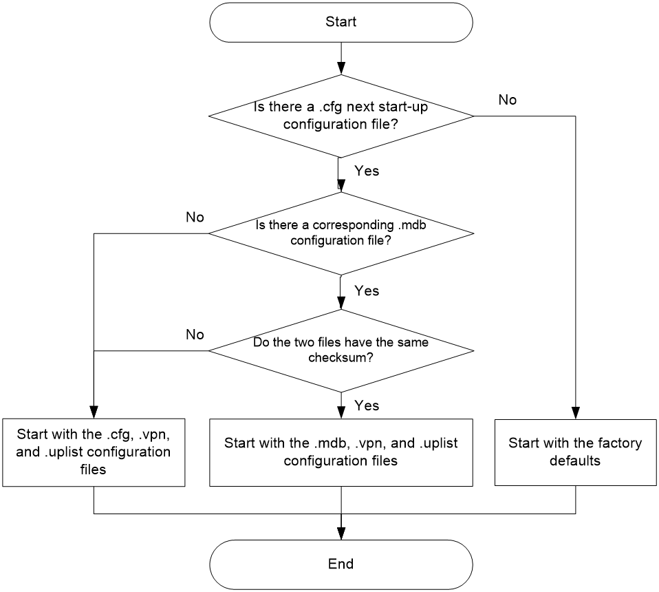
Unless otherwise stated, the term configuration file in this document refers to a .cfg configuration file.
Exporting configuration file
Export the running configuration to a .cfg file and save the file to the local disk.
Importing configuration file
After you upload the specified configuration file to the device, the file will be set as the next start-up configuration file. The imported configuration will take effect after the device is rebooted.
If you configure the device to execute the imported configuration immediately, the system will replace the running configuration with the imported configuration immediately, without requiring a reboot.
Viewing running configuration
You can view the running configuration of the device on this page.
Restoring factory defaults
Factory defaults are custom basic settings that came with the device.
The device starts up with the factory defaults if no next-startup configuration files are available.
When the usage scenario changes or the device fails, you can restore the device to its factory defaults, keeping only the .bin and license files as well as the apimge folder.
Software upgrade
Software upgrade enables you to upgrade a software version, add new features, and fix software bugs.
Before the upgrade, obtain the IPE file of the software compatible with the device according to the release notes and save the IPE file to the local endpoint. You can obtain the latest software version from H3C official website.
Reboot
You can manually reboot the device in either of the following ways:
· Reboot after saving the configuration. The device remains the current configuration after reboot.
· Reboot without any check. Unsaved configuration will be lost after reboot.
It takes about five minutes for the device to reboot. After the reboot, you need to log in to the web interface again.
About
You can view the following information on this page:
· Device information:
¡ Device name.
¡ Device serial number.
¡ Device model.
¡ Device description.
¡ Device location.
¡ Contact information.
· Version information.
· Electronic label.
· Legal statement.
Tools
Diagnostics
The system provides an interface to collect diagnostics information to help users diagnose and locate issues.
