- Table of Contents
-
- 17-BRAS Services Configuration Guide
- 00-Preface
- 01-AAA configuration
- 02-ANCP configuration
- 03-PPP configuration
- 04-Value-added services configuration
- 05-DHCP configuration
- 06-DHCPv6 configuration
- 07-User profile configuration
- 08-Connection limit configuration
- 09-L2TP configuration
- 10-PPPoE configuration
- 11-IPoE configuration
- 12-802.1X configuration
- 13-UCM configuration
- Related Documents
-
| Title | Size | Download |
|---|---|---|
| 10-PPPoE configuration | 1.00 MB |
Contents
Interaction process for PPPoE user onboarding
PPPoE MTU and MRU negotiation method
Restrictions and guidelines: PPPoE configuration
PPPoE server tasks at a glance
Setting the maximum number of PPPoE sessions
Limiting the PPPoE access rate
Configuring the NAS-Port-ID attribute
Configuring NAS-Port-ID binding for PPPoE access users
Setting a service name for the PPPoE server
Setting the maximum number of PADI packets that the device can receive per second
Configuring PPPoE user blocking
Configuring PPPoE protocol packet attack prevention
Forbidding PPPoE users from coming online through an interface
Set the response delay time for PPPoE user access
Specify the MAC address offset for response delay of PPPoE user access
PPPoE agency tasks at a glance
Configuring the PPPoE agency forwarding policy
Configuring the authentication domain for PPPoE agency users
Enabling the PPPoE agency gateway feature
Binding an interface to a PPPoE agency group
Enabling the PPPoE agency on an interface
Display and maintenance commands for PPPoE
Display and maintenance commands for PPPoE server
Display and maintenance commands for PPPoE agency
Example: Configuring the PPPoE server to assign IPv4 addresses through the local DHCP server
Example: Configuring the PPPoE server to assign IPv6 addresses through the IA_NA method
Example: Configuring the PPPoE server to assign IPv6 addresses through the IA_PD method
Example: Configuring the PPPoE server to assign IP addresses through the DHCPv4+NDRA+IA_PD method
Example: Configuring the PPPoE server to assign IPv6 addresses through the IA_NA+IA_PD method
Example: Assigning IP addresses to dual-stack users through the local DHCP server
Example: Configuring PPPoE server RADIUS-based IP address assignment
Example: Configuring PPPoE agency (ISP-side agency gateway+authorizing a remote BAS IP address pool)
Example: Configuring PPPoE static dual-stack users
Configuring PPPoE
About PPPoE
Point-to-Point Protocol over Ethernet (PPPoE) extends PPP by transporting PPP frames encapsulated in Ethernet over point-to-point links.
PPPoE specifies the methods for establishing PPPoE sessions and encapsulating PPP frames over Ethernet. PPPoE requires a point-to-point relationship between peers instead of a point-to-multipoint relationship as in multi-access environments such as Ethernet. PPPoE provides Internet access for the hosts in an Ethernet through a remote access device and implement access control, authentication, and accounting on a per-host basis. Integrating the low cost of Ethernet and scalability and management functions of PPP, PPPoE gained popularity in various application environments, such as residential access networks.
For more information about PPPoE, see RFC 2516.
PPPoE network structure
PPPoE uses the client/server model. The PPPoE client initiates a connection request to the PPPoE server. After session negotiation between them is complete, a session is established between them, and the PPPoE server provides access control, authentication, and accounting to the PPPoE client.
PPPoE network structures are classified into router-initiated and host-initiated network structures depending on the starting point of the PPPoE session.
Router-initiated network structure
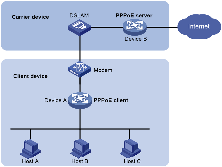
As shown in Figure 1, the PPPoE session is established between routers (Router A and Router B). All hosts share one PPPoE session for data transmission without being installed with PPPoE client software. This network structure is typically used by enterprises.
Figure 1 Router-initiated network structure
Host-initiated network structure
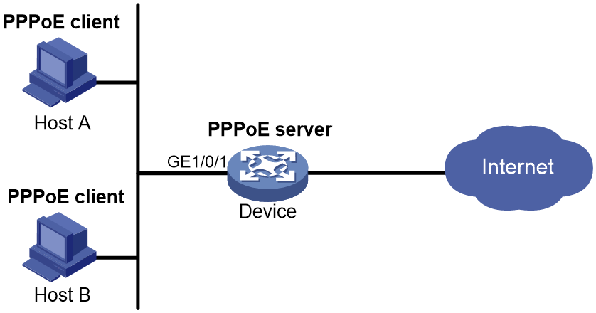
As shown in Figure 2, a PPPoE session is established between each host (PPPoE client) and the carrier router (PPPoE server). The service provider assigns an account to each host for billing and control. The host must be installed with PPPoE client software.
Figure 2 Host-initiated network structure
PPPoE packet structure
The format of PPPoE packets carries PPP packets in Ethernet frames. The encapsulation structure of the packets is as shown in Figure 3.
Figure 3 PPPoE packet structure
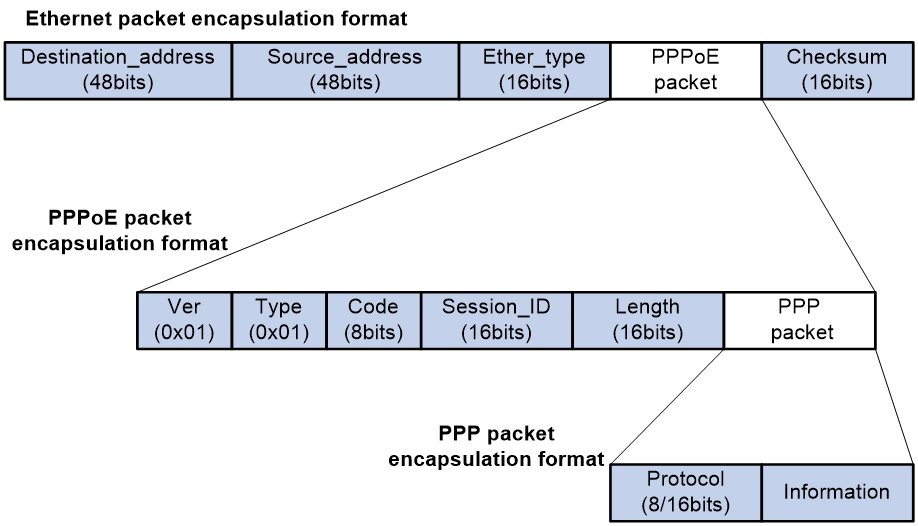
Table 1 Fields in the PPPoE packets
|
Field |
Description |
|
Destination address |
An Ethernet unicast destination address or Ethernet broadcast address (0xffffffffffff): · In the discovery phase, the field value is a unicast or broadcast address. The PPPoE client uses a broadcast address to find the PPPoE server, and then uses a unicast address after determining the PPPoE server. · In the session phase, this field must be the unicast address of the peer end determined during the discovery phase. |
|
Source_address |
Ethernet MAC address of the source device. |
|
Ether_type |
Set to 0x8863 (discovery phase) or 0x8864 (session phase). |
|
Ver |
4 bits long. This field represents the PPPoE version number. The value is 0x1. |
|
Type |
4 bits long. This field represents the PPPoE type. The value is 0x1. |
|
Code |
8 bits. This field represents the PPPoE packet type. Possible values include: · 0x00—Session data. · 0x09—PADI packet. · 0x07—PADO or PADT packet. · 0x19—PADR packet. · 0x65—PADS packet. |
|
Session_ID |
16 bits long. The value is fixed for a given PPP session and, in fact, defines a PPP session along with the Ethernet Source_address and Destination_address fields. The value of 0xffff is reserved for future use and must not be used. |
|
Length |
16 bits long. This field defines the length of the PPPoE payload. It does not include the length of the Ethernet or PPPoE headers. |
|
PPP packet |
For the PPP packet structure, see the frame format for PPP packet encapsulation in basic PPP concepts. |
Interaction process for PPPoE user onboarding
The PPPoE user onboarding process involves two phases: PPPoE negotiation and PPP negotiation. PPP negotiation includes LCP negotiation, PAP/CHAP authentication, NCP negotiation, and other phases.
PPPoE negotiation
In the PPPoE negotiation phase, the device assigns a session ID for the user's PPPoE access. A session ID uniquely identifies a virtual PPPoE link between the user and the device. The negotiation process of PPPoE is as shown in Figure 4.
1. The user broadcasts a PPPoE Active Discovery Initiation (PADI) packet, which contains the type of service the user wants.
2. Upon receiving this PADI packet, all access concentrators on the Ethernet (such as the device in the diagram) compare the requested service with their own capabilities. The device that can provide the service responds with a PPPoE Active Discovery Offer (PADO) packet.
3. The user might receive PADO packets from different devices. The user selects a device from the returned PADO packets based on certain conditions and sends to the device a non-broadcast session request packet, PPPoE Active Discovery Request (PADR). The PADR packet has the required service information encapsulated.
4. The selected device starts to enter the PPP session phase after receiving the PADR packet. The device will generate a session ID to uniquely identify the PPPoE session between the device and the host. The device includes this specific session ID in a session confirmation packet, PPPoE Active Discovery Session-confirmation (PADS), and sends the PADS packet to the user. If no errors occur, the device enters the PPP session phase. When the user receives the PADS packet, the user also enters the PPP session phase if no errors occur.
Figure 4 PPPoE negotiation process

PPP negotiation
PPP negotiation includes LCP negotiation, PAP/CHAP authentication, NCP negotiation, and other phases.
LCP negotiation
After the PPP negotiation phase starts, the LCP negotiation process starts first. The LCP negotiation process is as shown in Figure 5.
1. The user and the device send an LCP Configure-Request packet to each other.
2. After receiving the Configure-Request packet from the peer end, the local end responds appropriately based on the negotiation option support in the packet. For more information, see Table 2. If both ends have responded with a Configure-Ack packet, the LCP link has been successfully established. If not, both ends will continue to send requests.
¡ If the peer end responds with a Configure-Ack packet within the configured LCP negotiation interval and negotiation times, the LCP link has been successfully established.
¡ If the peer end has not responded with a Configure-Ack packet after the set LCP negotiation times, LCP negotiation will be terminated.
3. After the LCP link is successfully established, the device will periodically send LCP Echo-Requests to the user and then receive the Echo-Replies from the peer to detect whether the LCP link is normal and maintain the LCP connection.
Figure 5 Basic LCP negotiation process

Table 2 Response packet type list
|
Response packet type |
Description |
|
Configure-Ack |
If the end fully supports the LCP options of the peer end, the end responds with a Configure-Ack packet that fully carries the options in the request of the peer end. |
|
Configure-Nak |
If the end supports the negotiation options of the peer end but does not accept the negotiated content, the end responds with a Configure-Nak packet filled with the expected content. For example, if the MRU value of the peer is 1500 and the local end expects the MRU value of 1492, the local end will fill in 1492 in the Configure-Nak packet. |
|
Configure-Reject |
If the end does not support the negotiation options of the peer end, the end responds with a Configure-Reject packet carrying the unsupported options. |
Authentication phase
After the LCP negotiation is completed, the PPP link enters the authentication phase. Two authentication methods are supported: PAP authentication and CHAP authentication.
· PAP authentication
PAP is a two-way handshake protocol that authenticates a user by using a username and password. PAP transmits the username and password in plain text. Therefore, PAP is suitable for environments with relatively low network security requirements. The PAP authentication process is as shown in Figure 6.
a. The authenticatee sends the username and password to the authenticator.
b. The authenticator checks for this user in the user table at this end.
¡ If the user exists, the authenticator identifies whether the authentication password is correct.
- If the password is correct, the authenticator sends an Authenticate-ACK packet to the peer end to notify the peer end that it is allowed to enter the next phase of negotiation.
- If the password is not correct, the authenticator sends an Authenticate-NAK packet to the peer to notify the peer of authentication failure.
¡ If the user does not exist, the authentication will fail.
|
|
NOTE: After authentication failure, the link will not be directly closed. The link will be closed only when the number of authentication failures reaches a certain value. |
Figure 6 PAP authentication process

· CHAP authentication
CHAP is a three-way handshake protocol. CHAP transmits only the username rather than the user password over the network, so it is more secure than PAP. The authentication process of CHAP is as shown in Figure 7.
a. The authenticator initiates the authentication request, and sends a packet (Challenge) with a random number to the authenticatee and also sends the username to the authenticatee.
b. Upon receiving the authentication request from the authenticator, the authenticatee first identifies whether a CHAP password is configured on the local interface.
- If a CHAP password is configured, the authenticatee uses the hash algorithm to calculate a hash value based on the packet ID, configured password, and random number in the packet. Then, the authenticatee sends this hash value and the authenticatee's username (Response) back to the authenticator.
- If no CHAP password is configured, the authenticatee looks up the password corresponding to the username in the user table at this end based on the authenticator username in this packet. The authenticatee uses the hash algorithm to calculate a hash value based on the packet ID, the user's password, and the random number in the packet. The authenticatee sends the obtained hash value and the authenticatee's username back to the authenticator. (Response).
c. The authenticator uses the hash algorithm to calculate a hash value based on the packet ID, its saved password for the authenticatee, and the random number in the Challenge packet. The authenticator then compares the calculated hash value with the hash value in the Response packet. If the comparison result is consistent, authentication succeeds. If the comparison result is inconsistent, authentication fails.
Figure 7 CHAP authentication process

NCP negotiation
The main function of NCP negotiation is to negotiate network layer parameters of PPP packets, such as IPCP and IPv6CP, among which IPCP is the most common protocol. PPPoE users mainly obtain their IP addresses or IP address ranges for accessing the network through the IPCP protocol.
As shown in Figure 8, the NCP process is similar to the LCP process. When users and devices exchange Configure-Request packets and respond with Configure-Ack packets, NCP negotiation succeeds and users can normally access the network.
Figure 8 Basic NCP negotiation process

The following section will describe the commonly used IPCP and IPv6CP protocols in NCP negotiation.
· IPCP
The IPCP negotiation process is performed based on the PPP state machine. After both parties negotiate and they exchange configuration information through Configure-Request, Configure-Ack, and Configure-Nak packets, the IPCP state changes from initial (or closed) state to opened state finally. The condition for the IPCP state to become opened is that both the sender and receiver have sent and received Ack packets.
During the IPCP negotiation process, the negotiation packet can contain multiple options (parameters), such as IP address, gateway, and mask. The rejection or denial of each option does not affect the successful negotiation of IPCP, and IPCP also supports negotiation without options.
· IPv6CP
IPv6 Control Protocol (IPv6CP) is a network control protocol. IPv6CP is mainly responsible for configuring settings on both ends of a point-to-point link, enabling and disabling the IPv6 protocol module, and negotiating parameters such as interface ID and IPv6 compression protocol. IPv6CP uses the same packet exchange mechanism as the Link Control Protocol (LCP). However, the IPv6CP packets can be exchanged only when PPP reaches the network layer protocol phase. IPv6CP packets received before this phase will be dropped.
In the current software version, the IPv6CP negotiation options only support interface IDs and do not support the IPv6 compression protocols.
In an IPv6 network, PPP users and IPoE users both need to use the ND protocol or DHCPv6 protocol to allocate global unicast addresses and configuration information. The IA_PD option of the DHCPv6 protocol is used to allocate IPv6 prefixes to LAN interfaces in routed mode on CPEs.
PPPoE MTU and MRU negotiation method
During the interaction process of PPPoE user onboarding, the values of interface MTU and MRU will be negotiated, and then both sides will send and receive packets. The main negotiation methods include the following types.
The PPPoE connection is enabled to negotiate the MRU according to relevant standards
PPPoE discovery phase:
· If the user packet carries the PPP-Max-Payload field and the value is greater than 1492, the value will be compared with the MTU value on the BAS interface minus 8. The smaller value will be used as the negotiated value and named PPP_MRU_Max. This negotiated value is not the final MTU negotiation result, but one of the reference values.
· If the PPP-Max-Payload field carried in the user packet is less than or equal to 1492, PPP_MRU_Max takes the default value of 1492 as one of the reference values.
· If the user packet does not carry the PPP-Max-Payload field, then PPP_MRU_Max is set to 0 and not used as one of the reference values.
LCP negotiation phase:
· If the user carries the MRU field in the Config-Request packet during the LCP phase, the following rules apply:
¡ If the MRU carried in the user packet is equal to the PPP_MRU_Max negotiated in the PPPoE discovery phase, the MRU carried in the user packet will be used as the final MTU for the user.
¡ If the MRU carried in the user packet is not equal to the PPP_MRU_Max negotiated in the PPPoE discovery phase or the PPP_MRU_Max is 0, the MRU carried in the user packet will be compared with the MTU value on the VT interface minus 8. The smaller value will be used as the final MTU for the user.
· If the user's Config-Request packet during the LCP phase does not carry the MRU field, 1492 will be compared with the MTU value on the VT interface minus 8. The smaller value will be used as the final MTU for the user.
The PPPoE connection is disabled from negotiating the MRU according to relevant standards
PPPoE discovery phase:
· If the user packet carries the PPP-Max-Payload field, the smaller value between this value and the MTU on the BAS interface is used as the negotiated value and named PPP_MRU_Max. This value is not the final MTU negotiation result, but one of the reference values.
· If the user packet does not carry the PPP-Max-Payload field, the value for PPP_MRU_Max is the default value 0 and is not used as a reference value.
LCP negotiation phase:
· If the user includes the MRU field in the Config-Request packet during the LCP phase, the value will be compared with the MTU on the VT interface. The smaller value will be taken as the final MTU for the user.
· If the user does not include the MRU field in the Config-Request packet during the LCP phase, the following rules apply:
¡ If the user does not negotiate PPP_MRU_Max during the PPPoE discovery phase, the MTU on the VT interface will be used as the final MTU for the user.
¡ If PPP_MRU_Max is negotiated in the PPPoE discovery phase, the smaller value of the MTU on the VT interface and PPP-Max-Payload is used as the final MTU for the user.
PPPoE agency
To provide diversified network egresses for campus users and simplify the construction and O&M for the campus network, more and more universities select to cooperate with the ISPs to construct campus networks. In this scenario, you can deploy the PPPoE agency to allow a campus user to freely select an ISP network and use the simulated PPPoE client to initiate PPPoE dialup for network access to the PPPoE server in the corresponding ISP network. This feature not only simplifies the joint operations between the universities and ISPs but also provides good network access experience for students.
On a PPPoE agency network, the device that provides the PPPoE agency feature operates in either of the following modes:
· Unified PPPoE agency mode—In this mode, the campus BRAS also acts as the PPPoE agency device. The campus BRAS provides both BRAS access authentication and PPPoE agency features for campus users.
· PPPoE agency gateway mode—In this mode, a separate ISP BRAS (PPPoE agency gateway) rather than the campus BRAS provides the PPPoE agency feature. Depending on the deployment position, the PPPoE agency gateways include the following types:
¡ School-side agency gateway—Deployed on the campus network.
¡ ISP-side agency gateway—Deployed on the ISP network.
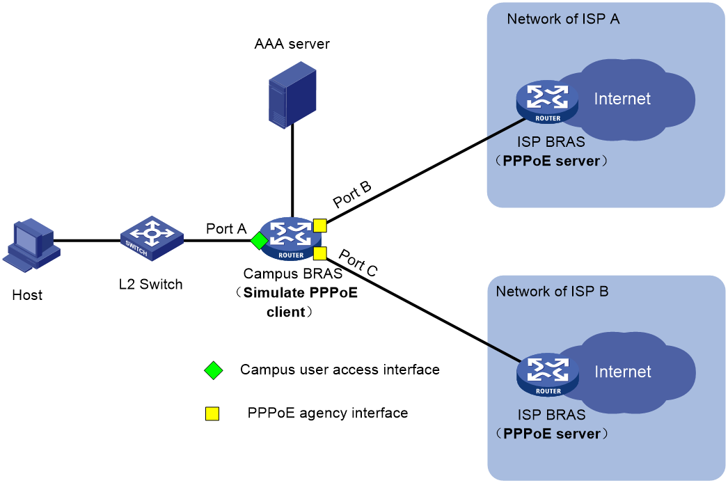
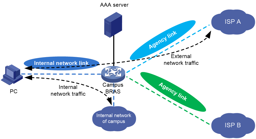
Unified PPPoE agency mode
As shown in Figure 9, in unified PPPoE agency mode, the campus BRAS also acts as the PPPoE agency device. The campus BRAS provides both BRAS access authentication and PPPoE agency features for campus users.
Figure 9 Schematic diagram for unified PPPoE agency mode
In unified PPPoE agency mode, the basic process of PPPoE agency is as follows:
1. Campus users subscribe to the ISP agency service from ISPs. The provided ISP agency accounts are bound to their campus accounts on the campus AAA server at the school. The binding operation can be done by campus users or by the campus network administrator after campus users report their accounts, depending on the campus AAA server capabilities.
2. After campus users use their campus accounts to pass authentication on the campus BRAS, the BRAS will maintain both campus access authentication user and PPPoE agency user identities for each user who has subscribed to the agency service. The BRAS processes traffic for these users as follows:
¡ For internal network traffic of campus users, the BRAS directly permits the traffic to pass through as the traffic of campus access authentication users (for example, IPoE users).
¡ For external network traffic of campus users, the BRAS processes the traffic as the traffic of PPPoE agency users.
3. When the campus AAA server receives the Accounting Start message about a user sent by the campus BRAS, the AAA server will notify the campus BRAS to initiate PPPoE agency for the accounting user through a COA message, which carries the information such as the agency account opened by the user.
4. The campus BRAS simulates a PPPoE client by using the agency account information in the COA messages, and then initiates PPPoE agency to the corresponding ISP's BRAS through the agency interface. The ISP's BRAS acts as the PPPoE server.
5. The ISP authenticates the PPPoE agency user. After the user passes authentication, the ISP allocates an IP address and other information to the PPPoE agency user through NCP negotiation.
6. After a successful agency dialup, the campus BRAS generates and maintains session information for the agency user.
7. When the campus BRAS receives external network traffic from a user, it replaces the source IP address of the packets with the IP address allocated by the ISP to the agency user. Then, the campus BRAS encapsulates the packets with PPPoE and forwards them to the corresponding ISP BRAS.
8. When the campus BRAS receives the returned external network traffic, it first removes the PPPoE encapsulation of the packets. Then, the campus BRAS replaces the destination IP address with the internal network IP address of the user and forwards the packets to the corresponding campus user.
School-side agency gateway
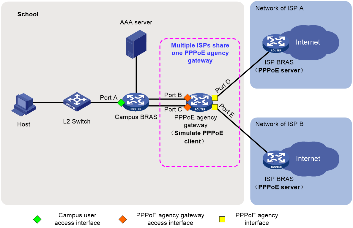
On the school-side agency gateway network, the following two networking schemes are supported:
· Multiple ISPs share a PPPoE agency gateway, as shown in Figure 10.
· Each ISP uses a separate PPPoE agency gateway, as shown in Figure 11.

Figure 11 Schematic diagram for school-side agency gateway network (one agency gateway per ISP)

On the school-side agency gateway network, the basic process of PPPoE agency is as follows:
1. Campus users subscribe to the ISP agency service from ISPs. The provided ISP agency accounts are bound to their campus accounts on the campus AAA server at the school. The binding operation can be done by campus users or by the campus network administrator after campus users report their accounts, depending on the campus AAA server capabilities.
2. After a campus user uses the campus account to pass authentication on the campus BRAS, the campus AAA server identifies whether the campus account is bound to an ISP agency account based on the campus account information.
3. If the campus AAA server finds that the campus account is bound to an ISP agency account, it notifies the PPPoE agency gateway to initiate PPPoE agency for the user through COA messages, which carry information such as the agency account opened by the user.
4. The PPPoE agency gateway simulates a PPPoE client by using the agency account information in the COA messages, and then initiates PPPoE agency to the corresponding ISP's BRAS through the agency interface. The ISP's BRAS acts as the PPPoE server.
5. The ISP authenticates the PPPoE agency user. After the user passes authentication, the ISP allocates an IP address and other information to the PPPoE agency user through NCP negotiation.
6. After a successful agency dialup, the PPPoE agency gateway generates and maintains session information for the agency user.
7. When the campus BRAS receives external network traffic from a user, it transmits the packet to the PPPoE agency gateway.
8. When the PPPoE agency gateway receives external network traffic from a user, it replaces the source IP address of the packets with the IP address allocated by the ISP to the agency user. Then, the PPPoE agency gateway encapsulates the packets with PPPoE and forwards them to the corresponding ISP BRAS.
9. When the PPPoE agency gateway receives the returned external network traffic, it first removes the PPPoE encapsulation of packets. Then, the PPPoE agency gateway replaces the destination IP address with the internal network IP address of the user, and at last forwards the packets to the campus BRAS.
10. When the campus BRAS receives returned traffic from the external network, it forwards the packets to the corresponding campus user based on the session information of the campus access authentication user.
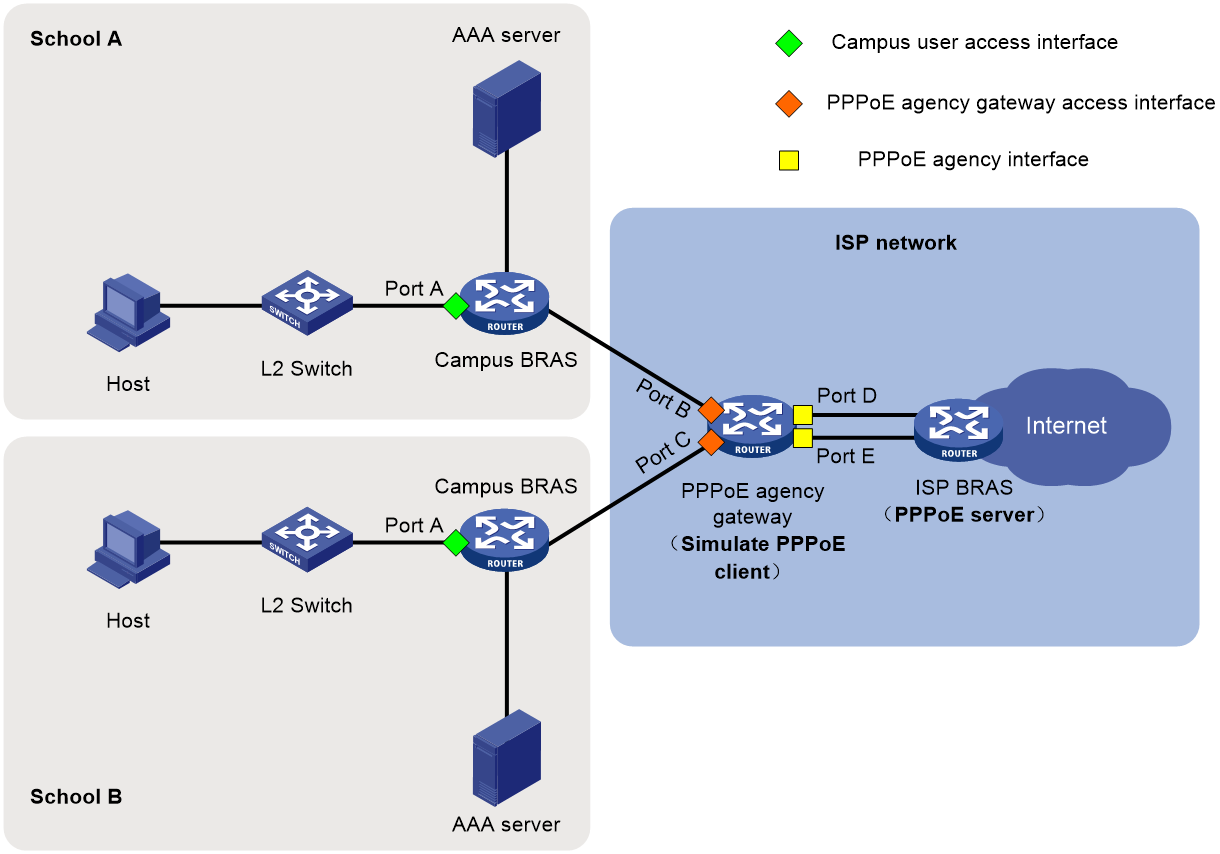
ISP-side agency gateway
As shown in Figure 12, a separate ISP BRAS (PPPoE agency gateway) rather than the campus BRAS provides the PPPoE agency feature.
Figure 12 Schematic diagram for PPPoE agency gateway mode
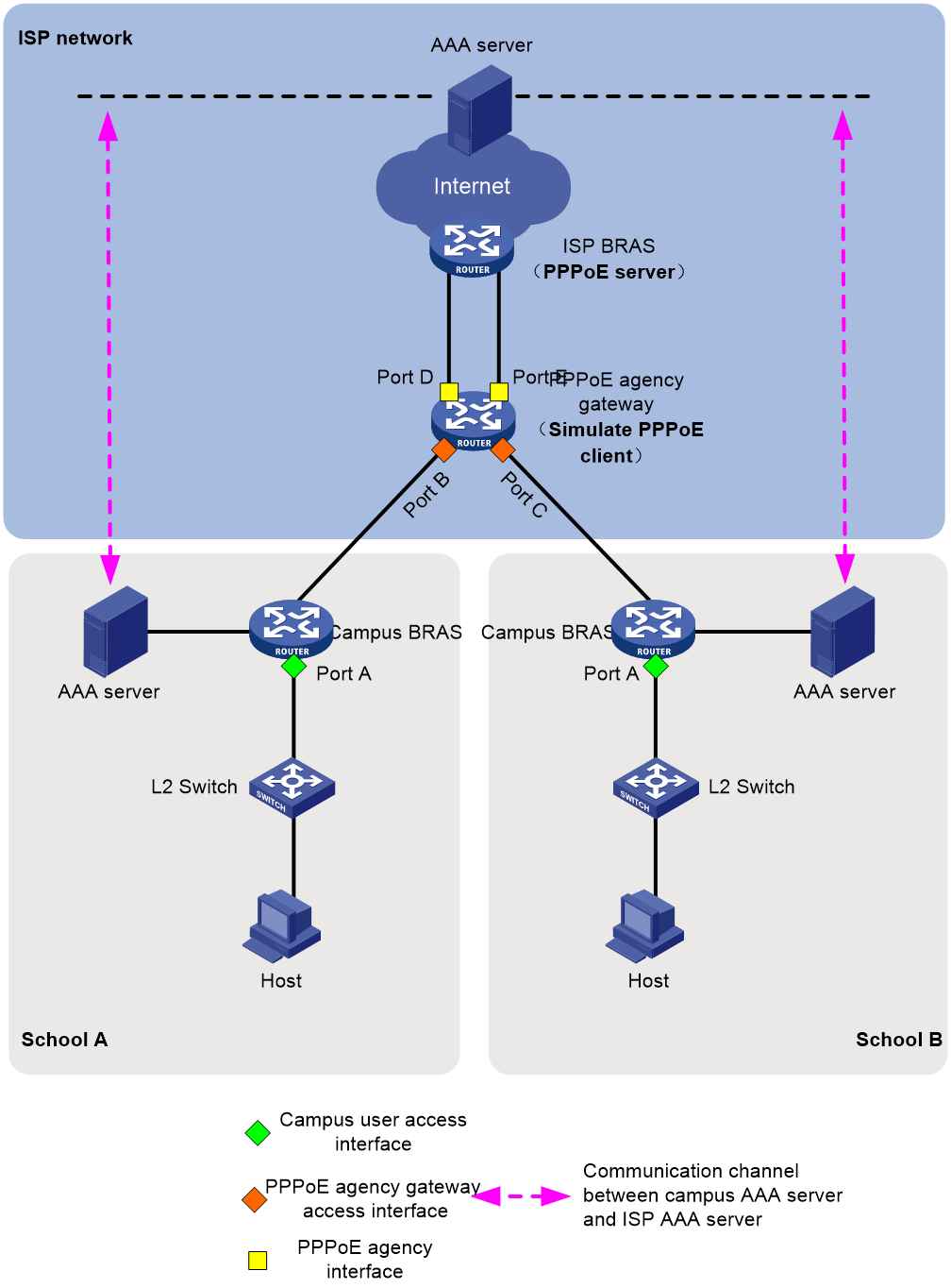
On the ISP-side agency gateway network, the basic process of PPPoE agency is as follows:
1. A communication channel is established between the campus AAA server and the ISP AAA server for transmitting information such as campus user accounts.
2. Campus users subscribe to the ISP agency service from an ISP. The ISP binds the provided ISP agency accounts to the campus accounts on the ISP AAA server.
3. After a campus user uses the campus account to pass authentication on the campus BRAS, the campus AAA server sends information such as the campus user account to the ISP AAA server through the established communication channel.
4. The ISP AAA server identifies whether the campus user account is bound to an agency account based on the information received.
5. If the ISP AAA server finds that the campus account is bound to an ISP agency account, it notifies the PPPoE agency gateway to initiate PPPoE agency for the user through COA messages, which carry information such as the agency account opened by the user.
6. The PPPoE agency gateway simulates a PPPoE client by using the agency account information in the COA messages, and then initiates PPPoE agency to the corresponding ISP's BRAS through the agency interface. The ISP's BRAS acts as the PPPoE server.
7. The ISP authenticates the PPPoE agency user. After the user passes authentication, the ISP allocates an IP address and other information to the PPPoE agency user through NCP negotiation.
8. After a successful agency dialup, the PPPoE agency gateway generates and maintains session information for the agency user.
9. When the campus BRAS receives external network traffic from a user, it transmits the packets to the PPPoE agency gateway.
10. When the PPPoE agency gateway receives external network traffic from a user, it replaces the source IP address of the packets with the IP address allocated by the ISP to the agency user. Then, the PPPoE agency gateway encapsulates the packets with PPPoE and forwards them to the corresponding ISP BRAS.
11. When the PPPoE agency gateway receives the returned external network traffic, it first removes the PPPoE encapsulation of packets. Then, the PPPoE agency gateway replaces the destination IP address with the internal network IP address of the user, and at last forwards the packets to the campus BRAS.
12. When the campus BRAS receives returned traffic from the external network, it forwards the packets to the corresponding campus user based on the session information of the campus access authentication user.
Protocols and standards
RFC 2516: A Method for Transmitting PPP Over Ethernet (PPPoE)
Restrictions and guidelines: PPPoE configuration
When you configure the PPPoE server feature, follow these restrictions and guidelines:
· The device can only act as a PPPoE server, and cannot act as a PPPoE client (except the simulated PPPoE client on the PPPoE agency network).
· In standard system operating mode, this feature is available only for the following cards:
Table 3 Card information
|
Card category |
Cards |
|
CEPC |
CEPC-XP4LX, CEPC-XP24LX, CEPC-XP48RX, CEPC-CP4RX, CEPC-CP4RX-L |
|
CSPEX |
CSPEX-1304X, CSPEX-1404X, CSPEX-1502X, CSPEX-1504X, CSPEX-1602X, CSPEX-1804X, CSPEX-1512X, CSPEX-1612X, CSPEX-1812X, CSPEX-1802X, CSPEX-1812X-E, CSPEX-2304X-G, CSPEX-2304X-LG |
|
SPE |
RX-SPE200, RX-SPE200-E |
· In SDN-WAN system operating mode, the device does not support this feature.
When you configure the PPPoE agency feature, follow these restrictions and guidelines:
· In standard system operating mode, this feature is available only for the following cards:
Table 4 Card information
|
Card category |
Cards |
|
CSPEX |
CSPEX-1802X, CSPEX-1812X-E, CSPEX-2304X-G, CSPEX-2304X-LG |
|
SPE |
RX-SPE200-E |
· In SDN-WAN system operating mode, the device does not support this feature.
· To provide the PPPoE agency service for a campus user that is a Layer 3 IPoE user, you must execute the pppoe-server session-limit per-mac command on the PPPoE server of the ISP to configure the maximum number of PPPoE sessions for each user to be greater than the actual number of internal campus users. If you cannot do that, the PPPoE agency users cannot come online due to MAC address conflicts.
· Make sure the user group configured with the PPPoE agency feature is different from a user group in a rule of an ACL packet filter configured by using the packet-filter command. If you cannot do that, the PPPoE agency feature does not take effect.
· Only the IPv4 multicast service supports the PPPoE agency feature. IPv6 and multicast do not support the PPPoE agency feature.
· In the PPPoE agency scenario, the PPPoE server on the ISP side supports only PAP and CHAP authentication methods, and does not support the MS-CHAP or MS-CHAPv2 authentication method.
· Both the access interfaces of agency gateways and the agency interfaces (in unified agency mode and agency gateway mode) only support Layer 3 Ethernet interfaces/subinterfaces and Layer 3 aggregate interfaces/subinterfaces. The access interfaces of agency gateways and the subinterfaces of agency interfaces must meet the following requirements:
¡ They support common VLAN termination, and do not support user VLAN termination.
¡ They support unambiguous dot1q termination and QinQ termination, and do not support ambiguous dot1q termination or QinQ termination.
¡ They do not support untagged termination or default termination.
In PPPoE applications, the advertisement pushing function takes effect only on HTTP packets with port number 80 or 8080.
When a PPPoE server acts as a DHCP relay agent, the following command settings must be the same on the DHCP relay agent and the remote DHCP server for a common IP address pool:
· In a DHCPv4 network:
¡ network: Specifies a network segment for dynamic allocation in an IP pool.
¡ address range: Configures an IP address range in an IP pool for dynamic allocation.
¡ forbidden-ip: Exclude IP addresses from dynamic allocation in an IP pool.
For more information about these commands, see BRAS Services Command Reference.
· In a DHCPv6 network:
¡ network: Specifies an IPv6 subnet for dynamic allocation in an IPv6 address pool.
¡ address range: Specifies a non-temporary IPv6 address range in an IPv6 address pool for dynamic allocation.
¡ forbidden-address: Excludes IPv6 addresses from dynamic allocation in an IPv6 address pool.
¡ forbidden-prefix: Excludes IPv6 prefixes from dynamic allocation in an IPv6 address pool.
¡ prefix-pool: Applies a prefix pool to an IPv6 address pool, so the DHCPv6 server can dynamically select a prefix from the prefix pool for a client.
For more information about these commands, see BRAS Services Command Reference.
Configuring the PPPoE server
PPPoE server tasks at a glance
To configure PPPoE server, perform the following tasks:
1. Configuring a PPPoE session
2. (Optional.) Setting the maximum number of PPPoE sessions
3. (Optional.) Enabling PPPoE logging
4. (Optional.) Limiting the PPPoE access rate
5. (Optional.) Configuring the NAS-Port-ID attribute
6. Configuring NAS-Port-ID binding for PPPoE access users
Perform this task if you need to acquire the physical location of the PPPoE user access interface by NAS-Port-ID.
7. (Optional.) Setting a service name for the PPPoE server
8. (Optional.) Setting the maximum number of PADI packets that the device can receive per second
9. (Optional.) Configuring PPPoE user blocking
10. (Optional.) Configuring PPPoE protocol packet attack prevention
11. (Optional.) Forbidding PPPoE users from coming online through an interface
12. (Optional.) Set the response delay time for PPPoE user access
13. (Optional.) Specify the MAC address offset for response delay of PPPoE user access
Configuring a PPPoE session
1. Enter system view.
system-view
2. Create a VT interface and enter VT interface view.
interface virtual-template number
3. Set PPP parameters.
When configuring PPP authentication, use the PPPoE server as the authenticator.
4. Return to system view.
quit
5. Enter interface view.
interface interface-type interface-number
6. Enable the PPPoE server on the interface and bind this interface to the specified VT interface.
pppoe-server bind virtual-template number
By default, the PPPoE server is disabled on the interface.
7. (Optional.) Configure an access concentrator (AC) name for the PPPoE server.
pppoe-server tag ac-name name
By default, the AC name for the PPPoE server is the device name.
PPPoE clients can choose a PPPoE server according to the AC name.
8. (Optional.) Enable the PPPoE server to support the ppp-max-payload tag and specify a range for the PPP maximum payload.
pppoe-server tag ppp-max-payload [ minimum min-number maximum max-number ]
By default, The PPPoE server does not support the ppp-max-payload tag.
9. Return to system view.
quit
10. Configure the PPPoE server to perform authentication, authorization, and accounting for PPP users.
For more information, see BRAS Services Configuration Guide.
Setting the maximum number of PPPoE sessions
About this task
PPPoE can establish a session when none of the following limits are reached:
· Limit for a user on an interface.
· Limit for a VLAN on an interface.
· Limit on an interface.
· (In standalone mode.) (In IRF mode.) Limit on a card.
Restrictions and guidelines for maximum number of PPPoE sessions
If the configured limit is smaller than the number of existing online sessions on the interface, the configuration succeeds. The configuration does not affect the existing online sessions. However, new sessions cannot be established on the interface.
(In standalone mode.) (In IRF mode.) The total maximum number of PPPoE sessions set for all cards or IRF member devices cannot be greater than the maximum number of PPPoE sessions supported by the device.
Setting the maximum number of PPPoE sessions in interface view
1. Enter system view.
system-view
2. Enter interface view.
interface interface-type interface-number
The PPPoE server is enabled on the interface.
3. Set the maximum number of PPPoE sessions.
¡ Set the maximum number of PPPoE sessions on an interface.
pppoe-server session-limit number
By default, the number of PPPoE sessions on an interface is not limited.
¡ Set the maximum number of PPPoE sessions for a VLAN.
pppoe-server session-limit per-vlan number
By default, the number of PPPoE sessions for a VLAN on an interface is not limited.
¡ Set the maximum number of PPPoE sessions for a user.
pppoe-server session-limit per-mac number
By default, a user is allowed to create a maximum of 1 PPPoE sessions.
Setting the maximum number of PPPoE sessions in system view
1. Enter system view.
system-view
2. Set the maximum number of PPPoE sessions.
In standalone mode:
pppoe-server session-limit slot slot-number [ cpu cpu-number ] total number
In IRF mode:
pppoe-server session-limit chassis chassis-number slot slot-number [ cpu cpu-number ] total number
By default, the number of PPPoE sessions is not limited.
Enabling PPPoE logging
About this task
The PPPoE logging feature enables the device to generate PPPoE logs and send them to the information center. Logs are generated when the following requirements are met:
· The number of PPPoE sessions reaches the upper limit for an interface, user, VLAN, or the system.
· New users request to come online.
A log entry records the interface-based, MAC-based, VLAN-based, or system-based session limit. For information about the log destination and output rule configuration in the information center, see Network Management and Monitoring Configuration Guide.
Restrictions and guidelines
As a best practice, disable this feature to prevent excessive PPP log output.
Procedure
1. Enter system view.
system-view
2. Enable PPPoE logging.
pppoe-server log enable
By default, PPPoE logging is disabled.
Limiting the PPPoE access rate
About this task
The device can limit the rate at which a user (identified by an MAC address) can create PPPoE sessions on an interface. If the number of PPPoE requests within the monitoring time reaches the configured threshold, the device discards the excessive requests, and outputs log messages. If the blocking time is set to 0, the device does not block any requests, and it only outputs log messages.
The device uses a monitoring table and a blocking table to control PPP access rates:
· Monitoring table—Stores a maximum of 8000 monitoring entries. Each entry records the number of PPPoE sessions created by a user within the monitoring time. When the monitoring entries reach the maximum, the system stops monitoring and blocking session requests from new users. The aging time of monitoring entries is determined by the session-request-period argument. When the timer expires, the system starts a new round of monitoring for the user.
· Blocking table—Stores a maximum of 8000 blocking entries. The system creates a blocking entry if the access rate of a user reaches the threshold, and blocks requests from that user. When the blocking entries reach the maximum number, the system stops blocking session requests from new users and it only outputs log messages. The aging time of the blocking entries is determined by the blocking-period argument. When the timer expires, the system starts a new round of monitoring for the user.
Restrictions and guidelines
If the access rate setting is changed, the system removes all monitoring and blocking entries, and uses the new settings to limit PPPoE access rates.
Procedure
1. Enter system view.
system-view
2. Enter interface view.
interface interface-type interface-number
The PPPoE server is enabled on the interface.
3. Set the PPPoE access limit.
pppoe-server throttle per-mac session-requests session-request-period blocking-period
By default, the PPPoE access rate is not limited.
Configuring the NAS-Port-ID attribute
About this task
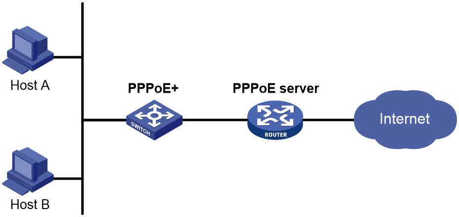
On the PPPoE+ network as shown in Figure 13 or on a network with a DSLAM, the PPPoE server on a BRAS uses the RADIUS NAS-Port-ID attribute to send the access line ID received from a PPPoE+ device (typically a switch with PPPoE+ deployed) or DSLAM device to the RADIUS server. The access line ID includes the circuit-id and remote-id. The RADIUS server compares the received NAS-Port-ID attribute with the local line ID information to verify the location of the user.
You can configure the content of the NAS-Port-ID attribute that the PPPoE server sends to the RADIUS server.
Figure 13 PPPoE+ network diagram
Restrictions and guidelines
If the attribute 87 format command is executed in RADIUS scheme view, the format of the NAS-Port-ID attribute sent to the RADIUS server is determined by using this command. In this case, the NAS-Port-ID attribute format defined in PPPoE does not take effect. For more information about the attribute 87 format command, see AAA commands in BRAS Services Command Reference.
Procedure
1. Enter system view.
system-view
2. Enter interface view.
interface interface-type interface-number
The PPPoE server is enabled on the interface.
Support for interface views depends on the device model.
3. Configure the content of the NAS-Port-ID attribute.
pppoe-server access-line-id content { all [ separator ] | circuit-id | remote-id }
By default, the NAS-Port-ID attribute contains only the circuit-id.
4. Configure the NAS-Port-ID attribute to include the BAS information automatically.
pppoe-server access-line-id bas-info [ cn-163 | cn-163-redback ]
By default, the NAS-Port-ID attribute does not include the BAS information automatically.
5. Configure the PPPoE server to trust the access line ID in received packets.
pppoe-server access-line-id trust
By default, the PPPoE server does not trust the access line ID in received packets.
6. Configure the transmission format for the circuit-id.
pppoe-server access-line-id circuit-id trans-format { ascii | hex }
The default format is a string of characters.
7. Configure the transmission format for the remote-id.
pppoe-server access-line-id remote-id trans-format { ascii | hex }
The default format is a string of characters.
8. Insert the VXLAN information into the NAS-Port-ID attribute.
pppoe-server access-line-id vxlan-info enable
By default, VXLAN information is not inserted into the NAS-Port-ID attribute.
Configuring NAS-Port-ID binding for PPPoE access users
About this task
a device uses information about the interface through which a user comes online to fill in the NAS-Port-ID attribute and sends it to the RADIUS server by default. In some special applications, when you need to manually specify the access interface information to be filled in the NAS-Port-ID attribute, you can use this command. For example, suppose the RADIUS server restricts user A's access to only interface A. When user A accesses through interface B and you do not want to modify the RADIUS server configuration, you can configure this command to use information about interface A to fill in the NAS-Port-ID attribute for user A and send the attribute to the RADIUS server.
When the BAS information format is China-Telecom 163 and the pppoe-server nas-port-id interface command is executed, the following rules apply:
· If the access-user four-dimension-mode enable command is also specified, the interface information specified in the pppoe-server nas-port-id interface command will be used to fill in the following access interface information field in the NAS-PORT-ID attribute:
¡ chassis=NAS_chassis;slot=NAS_slot;subslot=NAS_subslot;port=NAS_port.
· If the access-user four-dimension-mode enable command is not executed, the interface information specified in the pppoe-server nas-port-id interface command will be used to fill in the following access interface information field in the NAS-PORT-ID attribute: slot=NAS_slot;subslot=NAS_subslot;port=NAS_port.
When the BAS information format is China-Telecom and the pppoe-server nas-port-id interface command is executed, the following rules apply:
· If the access-user four-dimension-mode enable command is also executed, the interface information specified in the pppoe-server nas-port-id interface command will be used to fill in the following NAS information field in the NAS-PORT-ID attribute:
¡ {eth|trunk|atm} NAS_chassis/NAS_slot/NAS_subslot/NAS_port.
· If the access-user four-dimension-mode enable command is not executed, the interface information specified in the pppoe-server nas-port-id interface command will be used to fill in the following access interface information field in the NAS-PORT-ID attribute: {eth|trunk|atm} NAS_slot/NAS_subslot/NAS_port.
Restrictions and guidelines
If the attribute 87 format command is executed in RADIUS scheme view, the format of the NAS-Port-ID attribute sent to the RADIUS server is determined by using this command. In this case, the NAS-Port-ID attribute format defined in PPPoE does not take effect. For more information about the attribute 87 format command, see AAA commands in BRAS Command Reference.
This feature takes effect only when the corresponding interface is configured to automatically include BAS information in the NAS-Port-ID attribute by using the pppoe-server access-line-id bas-info command.
The information configured in this feature is also used to fill in the NAS-Port attribute.
Procedure
1. Enter system view.
system-view
2. Enter interface view.
interface interface-type interface-number
3. Configure the CP to use information of the specified interface on a UP to fill in the NAS-Port-ID attribute.
pppoe-server nas-port-id interface interface-type interface-number
By default, the CP uses information about the interface through which the user comes online to fill in the NAS-Port-ID attribute.
Setting a service name for the PPPoE server
About this task
Upon receiving a PADI or a PADR packet from a PPPoE client, the PPPoE server compares its service name with the service-name tag field of the packet. The server accepts the session establishment request only if the field matches the service name. Table 5 describes different matching rules in different matching modes.
Table 5 Service name matching rules
|
Matching mode |
PPPoE client |
PPPoE server |
Result |
|
Exact match |
No service name is specified. |
The number of configured service names is less than 8. |
Success |
|
The number of configured service names is 8. |
Failure |
||
|
A service name is specified. |
A service name that is the same as that of the client is configured. |
Success |
|
|
A service name that is the same as that of the client is not configured. |
Failure |
||
|
Fuzzy match |
No service name is specified. |
Any configuration. |
Success |
|
A service name is specified. |
A service name that is the same as that of the client is configured, or the number of configured service names is less than 8. |
Success |
|
|
A service name that is the same as that of the client is not configured, or the number of configured service names is 8. |
Failure |
Restrictions and guidelines
Service names identify the traffic destined for PPPoE servers when multiple PPPoE servers are providing services on the network.
You can configure a maximum of 8 service names on an interface.
Procedure
1. Enter system view.
system-view
2. Enter interface view.
interface interface-type interface-number
3. Configure the service name matching mode for the PPPoE server as exact match.
pppoe-server service-name-tag exact-match
By default, the service name matching mode for the PPPoE server is fuzzy match..
4. Set a service name for the PPPoE server.
pppoe-server tag service-name name
By default, the PPPoE server does not have a service name.
Setting the maximum number of PADI packets that the device can receive per second
About this task
When device reboot or version update is performed, the burst of online requests might affect the device performance. To avoid device performance degradation and make sure the device can process PADI packets correctly, use this feature to adjust the PADI packet receiving rate limit.
Restrictions and guidelines
Table 6 Default settings for the PADI packet receiving rate limit
|
MPU model |
PADI packet receiving rate limit |
|
CSR05SRP1L1 CSR05SRP1L3 CSR05SRP1P3 CSR05SRP1R3 CSR05SRP1R3A CSR05SRP1P3-G |
500 |
|
Other MPUs |
200 |
Procedure
1. Enter system view.
system-view
2. Set the maximum number of PADI packets that the LNS can receive per second.
In standalone mode:
pppoe-server padi-limit slot slot-number [ cpu cpu-number ] number
In IRF mode:
pppoe-server padi-limit chassis chassis-number slot slot-number [ cpu cpu-number ] number
The default varies by MPU model. For more information, see the preceding table.
Configuring PPPoE user blocking
About this task
You can use this feature to prevent multiple PPPoE users from frequently coming online and going offline or prevent protocol packet attacks. After this feature is enabled, users who performs the following operations for the specified number of times within a period will be blocked:
· Come online.
· Go offline.
· Send PPPoE connection requests.
Packets from blocked users will be discarded during the blocking period, and will be processed after the blocking period expires. At the same time, the device still performs PPPoE user blocking detection for PPPoE users within the blocking period. If the number of discarded packets meets the formula (number of discarded packets × request-period ≥requests × blocking-period) before the blocking period expires, the PPPoE users will be blocked for one more blocking period.
User blocking includes MAC-based user blocking and option105-based user blocking.
Restrictions and guidelines for PPPoE user blocking configuration
· If you enable this feature in system view, the feature applies to all PPPoE users.
· If you enable this feature in interface view, the feature applies to PPPoE users accessing the interface.
· If you execute this command in both system view and interface view, a user is monitored by blocking conditions in both views. When the user meets the blocking conditions in any view first, the user is blocked by the blocking settings in the view.
· If you enable MAC-based user blocking, the device uniquely identifies a blocked user by using its MAC address, the outermost VLAN ID, and the access interface.
· If you enable option105-based user blocking, the device uniquely identifies a blocked user by using its circuit ID, remote ID, and the access interface.
· In the unified scenario, when the blocking conditions are met, blocking entries are generated only for the slots hosting interfaces actually receiving packets. For example, when a user accessing a Layer 3 aggregate interface meets the blocking conditions, the blocking entries are generated only on the slots hosting member ports of the Layer 3 aggregate interface.
Enabling MAC-based user blocking in system view
1. Enter system view.
system-view
2. Enable MAC-based user blocking.
pppoe-server connection chasten [ quickoffline ] [ multi-sessions-permac ] requests request-period blocking-period
By default, a MAC-based PPPoE user will be blocked for 300 seconds if the user fails authentication consecutively for 120 times within 60 seconds.
Enabling MAC-based user blocking in interface view
1. Enter system view.
system-view
2. Enter interface view.
interface interface-type interface-number
The PPPoE server is enabled on the interface.
Support for interface views depends on the device model.
3. Enable MAC-based user blocking.
pppoe-server connection chasten [ quickoffline ] [ multi-sessions-permac ] requests request-period blocking-period
By default, MAC-based user blocking is disabled.
Enabling option105-based user blocking in system view
1. Enter system view.
system-view
2. Enable option105-based user blocking.
pppoe-server connection chasten option105 [ quickoffline ] requests request-period blocking-period
By default, option105-based user blocking is disabled.
Enabling option105-based user blocking in interface view
1. Enter system view.
system-view
2. Enter interface view.
interface interface-type interface-number
The PPPoE server is enabled on the interface.
Support for interface views depends on the device model.
3. Enable option105-based user blocking.
pppoe-server connection chasten option105 [ quickoffline ] requests request-period blocking-period
By default, option105-based user blocking is disabled.
Configuring PPPoE protocol packet attack prevention
About this task
In the Discovery phase of the PPPoE link establishment process, the PPPoE client sends PADI or PADR packets to find the PPPoE server that can provide the access service. After the PPPoE session is established, the PPPoE client can send PADT packets at any time to terminate the PPPoE session.
To prevent a large number of users frequently coming online and going offline or illegal users from initiating protocol packet attacks, which will occupy a large number of system resources, you can configure the PPPoE protocol packet attack prevention feature. With this feature configured, if the number of protocol packets that the PPPoE server receives within the detection interval exceeds the specified number, the PPPoE protocol packets received from the interface will be rate-limited. During the rate-limiting period, the excess PPPoE protocol packets are dropped. At the same time, the device still performs attack prevention detection for the interface within the rate-limiting period. If the number of PPPoE protocol packets dropped meets the formula (number of dropped packets × interval ≥ number ×rate-limit-period) before the rate-limiting period expires, one more rate-limiting period is added. After the rate-limiting period expires, the rate-limiting on the PPPoE protocol packets received from the interface is cancelled.
Restrictions and guidelines
You can configure PPPoE protocol packet attack prevention in system view and in interface view. The configuration in system view takes effect on all interfaces, and the configuration in interface view takes effect only on the current interface. If you configure this feature both in system view and interface view, the configuration in interface view takes priority.
Configuring PPPoE protocol packet attack prevention globally
1. Enter system view.
system-view
2. Enable PPPoE protocol packet attack prevention.
pppoe-server connection chasten per-interface number interval rate-limit-period
By default, PPPoE protocol packet attack prevention is disabled.
Configuring PPPoE protocol packet attack prevention on an interface
1. Enter system view.
system-view
2. Enter interface view.
interface interface-type interface-number
Make sure the interface has PPPoE server enabled.
3. Enable PPPoE protocol packet attack prevention.
pppoe-server connection chasten per-interface number interval rate-limit-period
By default, PPPoE protocol packet attack prevention is disabled.
Forbidding PPPoE users from coming online through an interface
About this task
With this feature configured on an interface, the interface directly drops received PADI and PADR packets to forbid users from coming online through this interface.
Restrictions and guidelines
This feature does not affect existing PPPoE users.
Procedure
1. Enter system view.
system-view
2. Enter interface view.
interface interface-type interface-number
3. Forbid PPPoE users from coming online through the interface.
pppoe-server block
By default, PPPoE users are permitted to come online.
Set the response delay time for PPPoE user access
About this task
Application scenarios
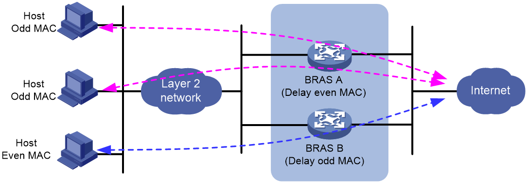
This feature is suitable for administrators to deploy multiple BRAS devices in the network, and distribute user loads and backups among these devices based on odd/even MAC addresses.
As shown in Figure 14, to provide device-level backup and traffic load balancing, two BRAS devices are deployed in the network, with the following configurations:
· Configure BRAS A to delay responses for users with even MAC addresses, and maintain the default setting (no response delay) for users with odd MAC addresses.
· Configure BRAS B to delay responses for users with odd MAC addresses, and maintain the default setting (no response delay) for users with even MAC addresses.
In this case, under normal circumstances, BRAS A responds to the online requests of users with odd MAC addresses before BRAS B, so users with odd MAC addresses prefer to come online through BRAS A. Similarly, BRAS B responds to the online requests of users with even MAC addresses before BRAS A, so users with even MAC addresses prefer to come online through BRAS B. This achieves load balancing of user traffic between BRAS A and BRAS B.
Figure 14 Response delay time functionality (both BRAS devices operate correctly)
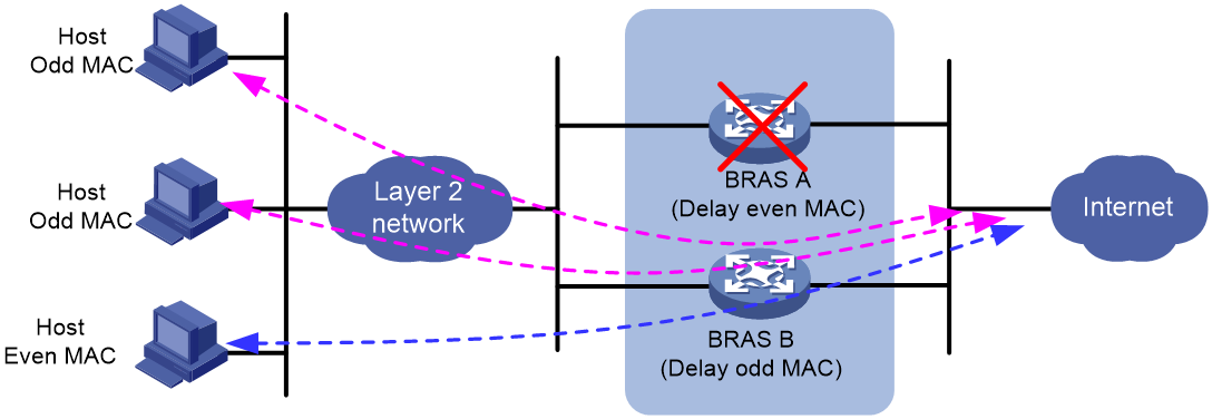
As shown in Figure 15, when a BRAS device (assuming BRAS A) malfunctions, BRAS B provides access services for all users, thus achieving device-level backup.
· For users with odd MAC addresses who have not come online before the failure of BRAS A, these users can directly come online through BRAS B.
· For users with odd MAC addresses who have come online before the failure of BRAS A, these users must disconnect first before they can come online through BRAS B.
Figure 15 Response delay time functionality (one BRAS device fails)
Operating mechanism
With the response delay time set for PPPoE user access, the system delays responses to the online requests of PPPoE users according to the configured time. You can set different response delay times for users with odd and even MAC addresses respectively.
Restrictions and guidelines
· In this scenario, you must configure address isolation between BRAS devices. Public address pools, private address pools, and NAS-IP addresses must be uniquely configured on each BRAS device and cannot be cross-utilized. If you cannot do that, route issues might occur. For example, if NAS-IP address 1.1.1.1 is configured on one BRAS device, then you cannot configure the NAS-IP address on another BRAS device as 1.1.1.1.
· You can use this feature in conjunction with the pppoe-server access-delay odd-even mac offset command to flexibly deploy access response delay strategies for odd and even MAC users based on MAC address offsets. For more information, see the pppoe-server access-delay odd-even mac offset command.
· This feature takes effect only for PPPoE users that attempt to come online afterward and has no impact on currently online PPPoE users.
Procedure
1. Enter system view.
system-view
2. Enter interface view.
interface interface-type interface-number
3. Set the response delay time for PPPoE user access.
pppoe-server access-delay delay-time [ even-mac | odd-mac ]
By default, no response delay time is set for PPPoE user access.
¡ If you specify either keyword, the configured response delay time applies to both odd MAC users and even MAC users who are newly connected from the current interface.
¡ If you specify this command twice, once with the even-mac or odd-mac keyword specified and once without any keyword specified, the most recent configuration takes effect.
Specify the MAC address offset for response delay of PPPoE user access
About this task
Application scenarios
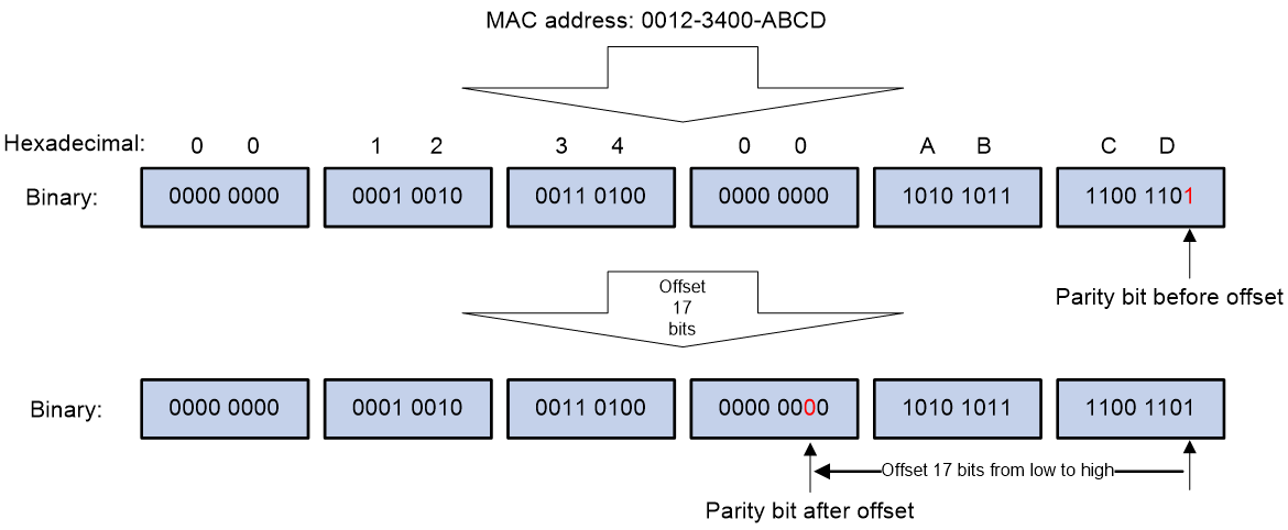
The parity bit is used by the BRAS device to determine the parity of a user's MAC address. In this context, the bit value of 0 indicates an even MAC address, while a value of 1 indicates an odd MAC address.
By default, the device only selects the lowest bit of a user's MAC address as the parity bit to determine the parity of the MAC address. It then uses the delay time configured by the pppoe-server access-delay command to delay the response to the user's online requests based on the parity of the MAC address.
To flexibly specify a certain bit in a user's MAC address as the basis for determining the parity of the address, you can specify the offset.
Operating mechanism
With the MAC address offset specified, when the device receives a PPPoE user's online request, it uses the principle of offsetting from the low bit to the high bit. The (offset-value+1)th bit of the user's MAC address is as the offset parity bit to determine whether the user's MAC address is odd or even. Then, based on the delay time for odd or even MAC addresses, the device delays the response to the user's online request.
For example, as shown in Figure 16, for a PPPoE user with MAC address 0012-3400-ABCD, the parity bit value for this MAC address is 1 by default, indicating an odd MAC address. If you set the offset value to 17 bits, the parity bit (starting from the default parity bit, the 17+1=18th bit) value for this user's MAC address becomes 0, indicating an even MAC address.
Figure 16 MAC address offset calculation
Restrictions and guidelines
· This feature must be used together with the pppoe-server access-delay command. If pppoe-server access-delay is not configured, the device responds to the access requests of PPPoE users immediately regardless of the configured MAC address offset value.
· This feature takes effect only for PPPoE users that attempt to come online afterward and has no impact on currently online PPPoE users.
Procedure
1. Enter system view.
system-view
2. Enter interface view.
interface interface-type interface-number
3. Specify the MAC address offset for response delay of PPPoE user access.
pppoe-server access-delay odd-even mac offset offset-value
By default, no offset is specified for matching the MAC addresses of PPPoE users. The parity of the MAC address is determined by the lowest bit of the MAC address (using the left-high and right-low principle).
If you execute this command multiple times, the most recent configuration takes effect.
Configuring the PPPoE agency
PPPoE agency tasks at a glance
PPPoE agency tasks at a glance in unified PPPoE agency mode
To configure PPPoE agency in unified PPPoE agency mode, perform the following tasks:
1. Configuring the PPPoE agency forwarding policy
2. Configuring the authentication domain for PPPoE agency users
3. Enabling the PPPoE agency on an interface
4. (Optional.) Enabling PPPoE agency logging
PPPoE agency tasks at a glance in PPPoE agency gateway mode
To configure PPPoE agency in PPPoE agency gateway mode, perform the following tasks:
1. Enabling the PPPoE agency gateway feature
2. Binding an interface to a PPPoE agency group
3. Enabling the PPPoE agency on an interface
Configuring the PPPoE agency forwarding policy
About this task
As shown in the following diagram, for an IPoE or PPPoE user in the campus network, if the AAA server of the campus network assigns the user a user group configured with a PPPoE agency forwarding policy when the user performs authentication, the user has the requirements to access the external network. The BRAS needs to perform PPPoE agency for the user according to the following process:
1. After the user passes authentication to come online, the BRAS will maintain the intra-campus access authentication user information for the campus user and also mark the user as a PPPoE agency user. That is, if a campus user also has an agency account, the BRAS will maintain two identities for the user.
¡ The BRAS processes the internal network traffic of the user in the traffic processing method for the access authentication user when the user comes online (for example, IPoE user) and directly forwards the internal network traffic.
¡ The BRAS processes the external network traffic of the user in the traffic processing method for the PPPoE agency user.
2. When the AAA server receives the Accounting-Start packets from a campus BRAS, the AAA server will send the COA messages to notify the campus BRAS to start the PPPoE agency process for the accounting user. The COA messages carry the ISP account opened for the user and the Frame-Pool attribute with the value as the PPPoE agency group name.
3. When the campus BRAS receives the COA messages, the BRAS simulates a PPPoE client and initiates PPPoE dialup to the PPPoE server of the corresponding ISP according to the account and PPPoE agency group name carried in the COA messages.
4. When the BRAS receives data traffic from the PPPoE agency user that has successfully comes online, the BRAS will consider the traffic that does not match the ACL in the PPPoE agency forwarding policy as the external network traffic and send the external network traffic to the corresponding ISP for processing.
Figure 17 Schematic diagram for PPPoE agency
Restrictions and guidelines
If a campus BRAS receives the external network traffic of a PPPoE agency user before the campus BRAS initiates PPPoE dialup for network access to the PPPoE server of the corresponding ISP, the campus BRAS directly drops the traffic.
In the current software version, only IPoE individual users and PPPoE users support the PPPoE agency feature. Among these users, IPoE Web individual users support the PPPoE agency feature only in the postauthentication phase, and do not support the PPPoE agency feature in the preauthentication phase.
Procedure
1. Enter system view.
system-view
2. Create a user group and enter its view.
user-group group-name
By default, the user group named system exists.
For more information about this command, see AAA commands in BRAS Services Command Reference.
3. Configure a PPPoE agency forwarding policy.
pppoe-agency forward { ipv4 | ipv6 } acl { acl-number | name acl-name }
By default, no PPPoE agency forwarding policy is configured.
Configuring the authentication domain for PPPoE agency users
About this task
When a campus BRAS simulates a PPPoE client and initiates PPPoE dialup for network access to the PPPoE server of the corresponding ISP according to the PPPoE agency group name carried in the COA messages, the BRAS first authenticates the PPPoE agency user according to the authentication domain specified in the pppoe-agency authentication domain command. If no authentication domain is specified by the pppoe-agency authentication domain command or the specified authentication domain does not exist, the BRAS uses the authentication domain selected by the AAA module. PPPoE agency can succeed only when the campus BRAS successfully authenticates the PPPoE agency user and the ISP PPPoE server successfully authenticates the PPPoE client. If the authentication on any end fails, PPPoE agency fails. In this case, the user can access only the internal network, and cannot access the external network.
Procedure
1. Enter system view.
system-view
2. Create a user group and enter its view.
user-group group-name
By default, the user group named system exists.
For more information about this command, see AAA commands in BRAS Services Command Reference.
3. Configure the authentication domain for PPPoE agency users.
pppoe-agency authentication domain domain-name
By default, no authentication domain is configured for PPPoE agency users.
Enabling the PPPoE agency gateway feature
About this task
To use a BRAS as a PPPoE agency gateway, you can enable the PPPoE agency gateway feature on that BRAS. With the PPPoE agency gateway feature enabled, the BRAS will act as a dedicated PPPoE agency gateway and will no longer support the unified PPPoE agency mode.
Restrictions and guidelines
When online PPPoEA users exist on a PPPoE agency gateway, you cannot execute the undo pppoe-agency-relay enable command to disable the PPPoE agency gateway feature. To do that, first execute the cut access-user command to log off all PPPoEA users, and then execute the undo pppoe-agency-relay enable command.
PPPoE agency gateways are used only for PPPoE agency networking. Non-PPPoE agency services (such as IPoE or L2TP) cannot be deployed on PPPoE agency gateways. Before executing this command on an agency gateway, make sure no non-PPPoEA users are online on the agency gateway. If non-PPPoEA users are online on the agency gateway, you cannot execute this command.
This command is mutually exclusive with the following commands:
· pppoe-agency authentication domain
· pppoe-agency forward
Procedure
1. Enter system view.
system-view
2. Enable the PPPoE agency gateway feature.
pppoe-agency-relay enable
By default, the PPPoE agency gateway feature is disabled.
Binding an interface to a PPPoE agency group
About this task
School-side agency gateway
On a school-side agency gateway network, the PPPoE agency gateway, as a school device, might be uplinked to multiple ISPs through different PPPoE agency interfaces. To differentiate traffic from different ISPs, use this command to bind the following elements:
· The PPPoE agency gateway access interface that is allocated to an ISP and connects to the campus BRAS.
· The agency group of the ISP.
For example, perform the following tasks for ISP A on the PPPoE agency gateway as shown in Figure 18:
· Use the pppoe-agency-relay-group command to bind the PPPoE agency gateway access interface Port B to the PPPoE agency group of ISP A.
· Use the pppoe-agency bind command to bind the PPPoE agency interface Port D to the PPPoE agency group of ISP A.
In this case, when the PPPoE agency gateway receives uplink traffic from users at school A through access interface Port B, it forwards the traffic through PPPoE agency interface Port D. Similarly, when the PPPoE agency gateway receives downlink traffic to users at school A through PPPoE agency interface Port D, it forwards the traffic through access interface Port B.
ISP-side agency gateway
On an ISP-side agency gateway network, the PPPoE agency gateway, as an ISP device, might be downlinked to multiple schools through different PPPoE agency gateway access interfaces. To differentiate traffic of users from different schools, you must use this command to bind the following elements:
· The interface connecting to the specified school on the PPPoE agency gateway.
· The agency group of the school.
For example, perform the following tasks on the PPPoE agency gateway for school A as shown in Figure 19:
· Use the pppoe-agency-relay-group command to bind the PPPoE agency gateway access interface Port B to the PPPoE agency group of school A.
· Use the pppoe-agency bind command to bind PPPoE agency interface Port D to the PPPoE agency group of school A.
In this case, when the PPPoE agency gateway receives uplink traffic from users at school A through access interface Port B, it forwards the traffic through PPPoE agency interface Port D. Similarly, when the PPPoE agency gateway receives downlink traffic to users at school A through PPPoE agency interface Port D, it forwards the traffic through access interface Port B.
Restrictions and guidelines
On the school-side PPPoE agency gateway, multiple ISPs cannot share the same PPPoE agency gateway access interface or PPPoE agency interface. Each ISP must have an exclusive pair of PPPoE agency gateway access interface and PPPoE agency interface, which can be main interfaces or subinterfaces.
On the ISP-side PPPoE agency gateway, multiple schools cannot share the same PPPoE agency gateway access interface or PPPoE agency interface. Each school must have an exclusive pair of PPPoE agency gateway access interface and PPPoE agency interface, which can be main interfaces or subinterfaces.
At a time, a PPPoE agency gateway access interface can be bound to only one PPPoE agency group, and vice versa. To change a binding between PPPoE agency group and PPPoE agency gateway access interface, first execute the undo pppoe-agency-relay-group command to remove the binding, and then execute the pppoe-agency-relay-group command to configure a new binding.
When online PPPoEA users exist on the PPPoE agency interface bound to a PPPoE agency group, follow these restrictions and guidelines:
· You cannot directly execute the undo pppoe-agency-relay-group command to remove the binding. To do that, first log off all online PPPoEA users on the PPPoE agency interface bound to the PPPoE agency group, and then execute the undo pppoe-agency-relay-group command.
· You cannot directly execute this command to modify the binding between the PPPoE agency group and the PPPoE agency gateway access interface. To do that, follow these steps:
¡ First, log off all online PPPoEA users on the PPPoE agency interface bound to the PPPoE agency group.
¡ Next, execute the undo pppoe-agency-relay-group command to remove the binding.
¡ Finally, execute the pppoe-agency-relay-group command to configure a new binding.
Procedure
1. Enter system view.
system-view
2. Bind an interface to a PPPoE agency group.
pppoe-agency-relay-group pppoe-agency-group-name interface interface-type interface-number peer-ip peer-ip-address
By default, an interface is not bound to any PPPoE agency group.
Enabling the PPPoE agency on an interface
About this task
With this feature configured, the device that provides the PPPoE agency feature operates in either of the following modes:
· Unified PPPoE agency mode—When a campus BRAS user initiates the agency process, the campus BRAS will select one interface that matches the PPPoE agency group name carried in COA messages from the interfaces with the pppoe-agency bind command executed (PPPoE agency interfaces, called agency interface for short). Then, the campus BRAS will use the selected interface to simulate a PPPoE client and initiate PPPoE dialup for network access to the PPPoE server of the corresponding ISP.
· PPPoE agency gateway mode—When a campus BRAS user initiates the agency process, the PPPoE agency gateway will select one interface that matches the PPPoE agency group name carried in COA messages from the interfaces with the pppoe-agency bind command executed (PPPoE agency interfaces, called agency interface for short). Then, the PPPoE agency gateway will use the selected interface to simulate a PPPoE client and initiate PPPoE dialup for network access to the PPPoE server of the corresponding ISP.
If the PPPoE agency group name carried in the COA messages authorized to a user matches the pppoe-agency-group-name argument value configured on multiple interfaces, the device will select the interface with the least online PPPoE agency users to simulate a PPPoE client for the user to perform PPPoE dialup. If multiple interfaces meet the requirements, the device randomly selects one from them.
Restrictions and guidelines
If an interface has the PPPoE agency enabled and is bound to a VT interface, you cannot directly use this command to bind the interface to a new VT interface. To do that, first disable the PPPoE agency on the interface, and then re-enable the PPPoE agency on the interface and bind it to a new VT interface.
When the PPPoE agency is enabled on an interface, the VT interface bound to the interface must exist.
If both the PPPoE client and PPPoE agency are enabled on an interface, the PPPoE client does not take effect.
On an interface, the pppoe-server bind command and the pppoe-agency bind command are mutually exclusive.
Procedure
1. Enter system view.
system-view
2. Enter interface view.
interface interface-type interface-number
3. Enable the PPPoE agency on an interface and bind the interface to a PPPoE agency group.
pppoe-agency bind virtual-template number pppoe-agency-group pppoe-agency-group-name
By default, the PPPoE agency is disabled on an interface.
Enabling PPPoE agency logging
About this task
The PPPoE agency logging feature enables the BRAS device to generate PPPoE agency logs and send them to the information center. Logs are generated when PPPoE agency users come online.
A log entry records the mapping between the internal IP address and the IP address assigned by the ISP to a PPPoE agency user. For information about the log destination and output rule configuration in the information center, see Network Management and Monitoring Configuration Guide.
Restrictions and guidelines
As a best practice, disable this feature to prevent excessive PPPoE agency log output.
This feature is supported only on a unified PPPoE agency network.
Procedure
1. Enter system view.
system-view
2. Enable PPPoE agency logging.
pppoe-agency log enable
By default, PPPoE agency logging is disabled.
Display and maintenance commands for PPPoE
Display and maintenance commands for PPPoE server
Execute display commands in any view and reset commands in user view.
|
Task |
Command |
|
Display PPPoE user blocking configuration information. |
display pppoe-server chasten configuration [ global | interface interface-type interface-number ] |
|
Display the PPPoE protocol packet attack prevention entries. |
In standalone mode: display pppoe-server chasten per-interface [ interface interface-type interface-number ] [ slot slot-number [ cpu cpu-number ] ] In IRF mode: display pppoe-server chasten per-interface [ interface interface-type interface-number ] [ chassis chassis-number slot slot-number [ cpu cpu-number ] ] |
|
Display the PPPoE protocol packet attack prevention configuration information. |
display pppoe-server chasten per-interface configuration [ interface interface-type interface-number ] |
|
Display statistics about PPPoE user blocking. |
In standalone mode: display pppoe-server chasten statistics [ mac-address | option105 ] [ interface interface-type interface-number ] [ slot slot-number [ cpu cpu-number ] ] In IRF mode: display pppoe-server chasten statistics [ mac-address | option105 ] [ interface interface-type interface-number ] [ chassis chassis-number slot slot-number [ cpu cpu-number ] ] |
|
Display information about blocked PPPoE users. |
In standalone mode: display pppoe-server chasten user [ mac-address [ mac-address ] | option105 [ circuit-id circuit-id ] [ remote-id remote-id ] ] [ interface interface-type interface-number ] [ slot slot-number [ cpu cpu-number ] ] [ verbose ] In IRF mode: display pppoe-server chasten user [ mac-address [ mac-address ] | option105 [ circuit-id circuit-id ] [ remote-id remote-id ] ] [ interface interface-type interface-number ] [ chassis chassis-number slot slot-number [ cpu cpu-number ] ] [ verbose ] |
|
Display PPPoE server negotiation packet statistics. |
In standalone mode: display pppoe-server packet statistics [ slot slot-number [ cpu cpu-number ] ] In IRF mode: display pppoe-server packet statistics [ chassis chassis-number slot slot-number [ cpu cpu-number ] ] |
|
Display summary information for PPPoE sessions. |
In standalone mode: display pppoe-server session summary [ [ interface interface-type interface-number | slot slot-number [ cpu cpu-number ] ] | mac-address mac-address ] * In IRF mode: display pppoe-server session summary [ [ interface interface-type interface-number | chassis chassis-number slot slot-number [ cpu cpu-number ] ] | mac-address mac-address ] * |
|
Display information about blocked users. |
In standalone mode: display pppoe-server throttled-mac { slot slot-number [ cpu cpu-number ] | interface interface-type interface-number } In IRF mode: display pppoe-server throttled-mac { chassis chassis-number slot slot-number [ cpu cpu-number ] | interface interface-type interface-number } |
|
Clear PPPoE sessions. |
reset pppoe-server { all | [ interface interface-type interface-number | mac-address mac-address ] * | virtual-template number } |
|
Clear PPPoE protocol packet attack prevention entry information. |
In standalone mode: reset pppoe-server chasten per-interface [ packets ] [ interface interface-type interface-number ] [ slot slot-number [ cpu cpu-number ] ] In IRF mode: reset pppoe-server chasten per-interface [ packets ] [ interface interface-type interface-number ] [ chassis chassis-number slot slot-number [ cpu cpu-number ] ] |
|
Clear information of blocked PPPoE users. |
In standalone mode: reset pppoe-server chasten user [ packets ] [ mac-address [ mac-address ] | option105 [ circuit-id circuit-id ] [ remote-id remote-id ] ] [ interface interface-type interface-number ] [ slot slot-number [ cpu cpu-number ] ] In IRF mode: reset pppoe-server chasten user [ packets ] [ mac-address [ mac-address ] | option105 [ circuit-id circuit-id ] [ remote-id remote-id ] ] [ interface interface-type interface-number ] [ chassis chassis-number slot slot-number [ cpu cpu-number ] ] |
|
Clear PPPoE server negotiation packet statistics. |
In standalone mode: reset pppoe-server packet statistics [ slot slot-number [ cpu cpu-number ] ] In IRF mode: reset pppoe-server packet statistics [ chassis chassis-number slot slot-number [ cpu cpu-number ] ] |
Display and maintenance commands for PPPoE agency
Execute display commands in any view and reset commands in user view.
|
Task |
Command |
|
Display statistics of packets matching ACLs in the PPPoE agency application. |
In standalone mode: display pppoe-agency { ipv4 | ipv6 } acl statistics user-group user-group-name slot slot-number [ cpu cpu-number ] In IRF mode: display pppoe-agency { ipv4 | ipv6 } acl statistics user-group user-group-name chassis chassis-number slot slot-number [ cpu cpu-number ] |
|
Display the PPPoE agency negotiation packet statistics. |
In standalone mode: display pppoe-agency packet statistics [ slot slot-number [ cpu cpu-number ] ] In IRF mode: display pppoe-agency packet statistics [ chassis chassis-number slot slot-number [ cpu cpu-number ] ] |
|
Display summary information of the PPPoE agency user sessions. |
In standalone mode: display pppoe-agency session summary [ interface interface-type interface-number | slot slot-number [ cpu cpu-number ] ] In IRF mode: display pppoe-agency session summary [ interface interface-type interface-number | chassis chassis-number slot slot-number [ cpu cpu-number ] ] |
|
Clear the PPPoE agency sessions on the PPPoE agency. |
reset pppoe-agency { all | interface interface-type interface-number | virtual-template number } |
|
Clear statistics of packets matching ACLs in the PPPoE agency application. |
In standalone mode: reset pppoe-agency { ipv4 | ipv6 } acl statistics user-group user-group-name slot slot-number [ cpu cpu-number ] In IRF mode: reset pppoe-agency { ipv4 | ipv6 } acl statistics user-group user-group-name chassis chassis-number slot slot-number [ cpu cpu-number ] |
|
Clear the PPPoE agency negotiation packet statistics. |
In standalone mode: reset pppoe-agency packet statistics [ slot slot-number [ cpu cpu-number ] ] In IRF mode: reset pppoe-agency packet statistics [ chassis chassis-number slot slot-number [ cpu cpu-number ] ] |
PPPoE configuration examples
Example: Configuring the PPPoE server to assign IPv4 addresses through the local DHCP server
Network configuration
As shown in Figure 20, configure the PPPoE server as a DHCP server to assign an IP address to the host.

Procedure
# Configure Virtual-Template 1 to use CHAP for authentication.
<Router> system-view
[Router] interface virtual-template 1
[Router-Virtual-Template1] ppp authentication-mode chap domain dm1
# Enable the PPPoE server on Ten-GigabitEthernet 3/1/1, and bind the interface to Virtual-Template 1.
[Router] interface ten-gigabitethernet 3/1/1
[Router-Ten-GigabitEthernet3/1/1] pppoe-server bind virtual-template 1
[Router-Ten-GigabitEthernet3/1/1] quit
# Enable DHCP.
[Router] dhcp enable
# Configure local BAS IP address pool pool1.
[Router] ip pool pool1 bas local
[Router-ip-pool-pool1] gateway 1.1.1.1 24
[Router-ip-pool-pool1] dns-list 8.8.8.8
# Exclude the IP address 1.1.1.1 from dynamic allocation in IP address pool pool1.
[Router-ip-pool-pool1] forbidden-ip 1.1.1.1
[Router-ip-pool-pool1] quit
# Create a PPPoE user.
[Router] local-user user1 class network
[Router-luser-network-user1] password simple 123456TESTplat&!
[Router-luser-network-user1] service-type ppp
[Router-luser-network-user1] quit
# In ISP domain dm1, perform local AAA for PPP users and authorize an address pool.
[Router] domain name dm1
[Router-isp-dm1] authentication ppp local
[Router-isp-dm1] accounting ppp local
[Router-isp-dm1] authorization ppp local
[Router-isp-dm1] authorization-attribute ip-pool pool1
[Router-isp-dm1] quit
Verifying the configuration
# Log in to the router by using username user1 and password 123456TESTplat&!.
# Display information about IP addresses assigned by the DHCP server.
[Router] display access-user interface ten-gigabitethernet 3/1/1
UserID Interface IP address MAC address S-/C-VLAN
Username Access type
IPv6 address
0xc XGE3/1/1 1.1.1.2 001b-21a8-0949 -/-
user1 PPPoE
-
The output shows that the router has assigned an IP address to the host.
Example: Configuring the PPPoE server to assign IP addresses to dual-stack users through a remote DHCP server
Network configuration
As shown in Figure 21, configure the PPPoE server as a DHCP relay agent to relay an IPv4 address and an IPv6 address from the DHCP server to the host.
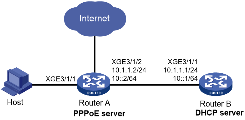
Prerequisites
Assign IP addresses to interface, and make sure the devices can reach each other at Layer 3. (Details not shown.)
Procedure
1. Configure Router A as the PPPoE server:
# Configure Virtual-Template 1 to use CHAP for authentication.
<RouterA> system-view
[RouterA] interface virtual-template 1
[RouterA-Virtual-Template1] ppp authentication-mode chap domain dm1
# Enable Virtual-Template 1 to advertise RA messages.
[RouterA-Virtual-Template1] undo ipv6 nd ra halt
# Set the managed address configuration flag (M) to 1 in RA advertisements to be sent on Virtual-Template 1.
[RouterA-Virtual-Template1] ipv6 nd autoconfig managed-address-flag
# Set the other stateful configuration flag (O) to 1 in RA advertisements to be sent on Virtual-Template 1.
[RouterA-Virtual-Template1] ipv6 nd autoconfig other-flag
[RouterA-Virtual-Template1] quit
# Enable the PPPoE server on Ten-GigabitEthernet 3/1/1, and bind the interface to Virtual-Template 1.
[RouterA] interface ten-gigabitethernet 3/1/1
[RouterA-Ten-GigabitEthernet3/1/1] pppoe-server bind virtual-template 1
[RouterA-Ten-GigabitEthernet3/1/1] quit
# Enable DHCP.
[RouterA] dhcp enable
# Create remote BAS IP address pool pool1.
[RouterA] ip pool pool1 bas remote
# Specify a gateway address for the clients in pool1.
[RouterA-ip-pool-pool1] gateway 1.1.1.1 24
# Exclude IP address 1.1.1.1 from dynamic allocation in pool1.
[RouterA-ip-pool-pool1] forbidden-ip 1.1.1.1
# Specify a DHCP server for pool1.
[RouterA-ip-pool-pool1] remote-server 10.1.1.1
[RouterA-ip-pool-pool1] quit
# Create an IPv6 address pool named pool2.
[RouterA] ipv6 pool pool2
# Specify gateway address 1::1 for DHCPv6 clients in the IPv6 address pool.
[RouterA-ipv6-pool-pool2] gateway-list 1::1
# Specify the subnet 1::/64 for dynamic allocation in the IPv6 address pool.
[RouterA-ipv6-pool-pool2] network 1::/64 export-route
# Exclude IPv6 address 1::1 from dynamic allocation in the IPv6 address pool.
[RouterA-ipv6-pool-pool2] forbidden-address 1::1
# Specify DHCPv6 server 10::1 for the IPv6 address pool.
[RouterA-ipv6-pool-pool2] remote-server 10::1
[RouterA-ipv6-pool-pool2] quit
# Enable the DHCPv4 relay agent and DHCPv6 relay agent on Ten-GigabitEthernet 3/1/1.
[RouterA] interface ten-gigabitethernet 3/1/1
[RouterA–Ten-GigabitEthernet3/1/1] dhcp select relay
[RouterA–Ten-GigabitEthernet3/1/1] ipv6 dhcp select relay
[RouterA–Ten-GigabitEthernet3/1/1] ipv6 dhcp relay release-agent
# Configure Ten-GigabitEthernet 3/1/1 to automatically generate a link-local address, which is to be used as the gateway of users.
[RouterA–Ten-GigabitEthernet3/1/1] ipv6 address auto link-local
# Enable Ten-GigabitEthernet 3/1/1 to advertise RA messages.
[RouterA–Ten-GigabitEthernet3/1/1] undo ipv6 nd ra halt
[RouterA–Ten-GigabitEthernet3/1/1] quit
# Create a PPPoE user.
[RouterA] local-user user1 class network
[RouterA-luser-network-user1] password simple 123456TESTplat&!
[RouterA-luser-network-user1] service-type ppp
[RouterA-luser-network-user1] quit
# In ISP domain dm1, perform local AAA for PPP users and authorize an address pool.
[RouterA] domain name dm1
[RouterA-isp-dm1] authentication ppp local
[RouterA-isp-dm1] accounting ppp local
[RouterA-isp-dm1] authorization ppp local
[RouterA-isp-dm1] authorization-attribute ip-pool pool1
[RouterA-isp-dm1] authorization-attribute ipv6-pool pool2
[RouterA-isp-dm1] quit
2. Configure Router B as a DHCP server:
¡ Configure an IPv4 address pool:
# Enable DHCP.
<RouterB> system-view
[RouterB] dhcp enable
# Create IPv4 address pool pool1. Specify a subnet for dynamic allocation and specify a gateway address and a DNS server address for DHCP clients in the IPv4 address pool.
[RouterB] ip pool pool1
[RouterB-ip-pool-pool1] network 1.1.1.0 24
[RouterB-ip-pool-pool1] gateway-list 1.1.1.1
[RouterB-ip-pool-pool1] dns-list 8.8.8.8
# Exclude the IP address 1.1.1.1 from dynamic allocation in IPv4 address pool pool1.
[RouterB-ip-pool-pool1] forbidden-ip 1.1.1.1
[RouterB-ip-pool-pool1] quit
# Configure the default route to the PPPoE server.
[RouterB] ip route-static 0.0.0.0 0 10.1.1.2
¡ Configure an IPv6 address pool:
# Create IPv6 address pool pool2. Specify a subnet for dynamic allocation and specify a DNS server address for DHCP clients in the IPv6 address pool.
[RouterB] ipv6 pool pool2
[RouterB-ipv6-pool-pool2] network 1::/64
[RouterB-ipv6-pool-pool2] dns-server 8::8
# Exclude the IPv6 address 1::1 from dynamic allocation in IPv6 address pool pool2.
[RouterB-ipv6-pool-pool2] forbidden-address 1::1
[RouterB-ipv6-pool-pool2] quit
# Enable the DHCPv6 server on Ten-GigabitEthernet 3/1/1.
[RouterB] interface ten-gigabitethernet 3/1/1
[RouterB-Ten-GigabitEthernet3/1/1] ipv6 dhcp select server
[RouterB-Ten-GigabitEthernet3/1/1] quit
# Configure the default route to the PPPoE server.
[RouterB] ipv6 route-static :: 0 10::2
Verifying the configuration
# Verify that a host is assigned an IPv4 address and an IPv6 address after logging in to Router A by using username user1 and password 123456TESTplat&! through PPPoE.
[RouterA] display access-user interface ten-gigabitethernet 3/1/1
UserID Interface IP address MAC address S-/C-VLAN
Username Access type
IPv6 address
0xc XGE3/1/1 1.1.1.2 001b-21a8-0949 -/-
user1 PPPoE
1::2
Example: Configuring the PPPoE server to assign IPv6 addresses through the NDRA method (prefixes authorized by AAA)
Network configuration
As shown in Figure 22, configure the PPPoE server to advertise the following information to the host:
· IPv6 prefix in RA messages.
· IPv6 interface identifier during IPv6CP negotiation.
The host uses the IPv6 prefix and IPv6 interface identifier to generate an IPv6 global unicast address. The IPv6 address prefixes in RA packets are authorized prefixes.

Procedure
# Create Virtual-Template 1.
<Router> system-view
[Router] interface virtual-template 1
# Configure Virtual-Template 1 to use CHAP to authenticate the peer.
[Router-Virtual-Template1] ppp authentication-mode chap domain dm1
# Enable Virtual-Template 1 to advertise RA messages.
[Router-Virtual-Template1] undo ipv6 nd ra halt
[Router-Virtual-Template1] quit
# Configure Ten-GigabitEthernet 3/1/1 to automatically generate an IPv6 link-local address.
[Router] interface ten-gigabitethernet 3/1/1
[Router-Ten-GigabitEthernet3/1/1] ipv6 address auto link-local
# Enable Ten-GigabitEthernet 3/1/1 to advertise RA messages.
[Router-Ten-GigabitEthernet3/1/1] undo ipv6 nd ra halt
# Enable the PPPoE sever on Ten-GigabitEthernet 3/1/1, and bind the interface to Virtual-Template 1.
[Router-Ten-GigabitEthernet3/1/1] pppoe-server bind virtual-template 1
[Router-Ten-GigabitEthernet3/1/1] quit
# (Applicable only to advertising prefix subnet routes.) Create an IPv6 address pool and enter its view. Specify the subnet for DHCPv6 clients and advertise the subnet route.
[Router] ipv6 pool pool1
[Router-ipv6-pool-pool1] network 10::/64 export-route
[Router-ipv6-pool-pool1] quit
# Configure a PPPoE user.
[Router] local-user user1 class network
[Router-luser-network-user1] password simple 123456TESTplat&!
[Router-luser-network-user1] service-type ppp
[Router-luser-network-user1] quit
# Configure local AAA for the PPP users in the ISP domain dm1.
[Router] domain name dm1
[Router-isp-dm1] authentication ppp local
[Router-isp-dm1] accounting ppp local
[Router-isp-dm1] authorization ppp local
# Configure an IPv6 prefix and a DNS server authorized to the users in the ISP domain dm1.
[Router-isp-dm1] authorization-attribute ipv6-prefix 10:: 64
[Router-isp-dm1] authorization-attribute primary-dns ipv6 8::8
[Router-isp-dm1] quit
Verifying the configuration
# Display PPP user information on Ten-GigabitEthernet 3/1/1.
[Router] display access-user interface Ten-GigabitEthernet 3/1/1
UserID Interface IP address MAC address S-/C-VLAN
Username Access type
IPv6 address
0x6 XGE3/1/1 - 001b-21a8-0949 -/-
user1 PPPoE
10::F85B:7EE1:1410:74C9
Example: Configuring the PPPoE server to assign IPv6 addresses through the NDRA method (prefixes authorized by ND prefix pool)
Network configuration
As shown in Figure 22, configure the PPPoE server to advertise the following information to the host:
· IPv6 prefix in RA messages.
· IPv6 interface identifier during IPv6CP negotiation.
The host uses the IPv6 prefix and IPv6 interface identifier to generate an IPv6 global unicast address. The IPv6 address prefixes in RA packets are authorized prefixes.
Figure 23 Network diagram

Procedure
# Create Virtual-Template 1.
<Router> system-view
[Router] interface virtual-template 1
# Configure Virtual-Template 1 to use CHAP to authenticate the peer.
[Router-Virtual-Template1] ppp authentication-mode chap domain dm1
# Enable Virtual-Template 1 to advertise RA messages.
[Router-Virtual-Template1] undo ipv6 nd ra halt
[Router-Virtual-Template1] quit
# Configure Ten-GigabitEthernet 3/1/1 to automatically generate an IPv6 link-local address.
[Router] interface ten-gigabitethernet 3/1/1
[Router-Ten-GigabitEthernet3/1/1] ipv6 address auto link-local
# Enable Ten-GigabitEthernet 3/1/1 to advertise RA messages.
[Router-Ten-GigabitEthernet3/1/1] undo ipv6 nd ra halt
# Enable the PPPoE sever on Ten-GigabitEthernet 3/1/1, and bind the interface to Virtual-Template 1.
[Router-Ten-GigabitEthernet3/1/1] pppoe-server bind virtual-template 1
[Router-Ten-GigabitEthernet3/1/1] quit
# Create prefix pool 1, and specify the prefix 10::/32 with the assigned prefix length 64. Prefix pool 1 contains 4294967296 prefixes from 10::/64 to 10:0:FFFF:FFFF::/64.
[Router] ipv6 dhcp prefix-pool 1 prefix 10::/32 assign-len 64
# Create an IPv6 address pool named pool1, and apply prefix pool 1 to the address pool.
[Router] ipv6 pool pool1
[Router-ipv6-pool-pool1] prefix-pool 1 export-route
[Router-ipv6-pool-pool1] quit
# Configure a PPPoE user.
[Router] local-user user1 class network
[Router-luser-network-user1] password simple 123456TESTplat&!
[Router-luser-network-user1] service-type ppp
[Router-luser-network-user1] quit
# Configure local AAA for the PPP users in the ISP domain dm1.
[Router] domain name dm1
[Router-isp-dm1] authentication ppp local
[Router-isp-dm1] accounting ppp local
[Router-isp-dm1] authorization ppp local
# Authorize ND prefix pool pool1 and the primary DNS server to users in the ISP domain dm1.
[Router-isp-dm1] authorization-attribute ipv6-nd-prefix-pool pool1
[Router-isp-dm1] authorization-attribute primary-dns ipv6 8::8
[Router-isp-dm1] quit
Verifying the configuration
# Display PPP user information on Ten-GigabitEthernet 3/1/1.
[Router] display access-user interface Ten-GigabitEthernet 3/1/1
UserID Interface IP address MAC address S-/C-VLAN
Username Access type
IPv6 address
0x6 XGE3/1/1 - 001b-21a8-0949 -/-
user1 PPPoE
10::F85B:7EE1:1410:74C9
Example: Configuring the PPPoE server to assign IPv6 addresses through the IA_NA method
Network configuration
As shown in Figure 24, configure the PPPoE server to assign an IPv6 address to the host through DHCPv6.

Procedure
# Create Virtual-Template 1.
<Router> system-view
[Router] interface virtual-template 1
# Configure Virtual-Template 1 to use CHAP to authenticate the peer.
[Router-Virtual-Template1] ppp authentication-mode chap domain dm1
# Enable Virtual-Template 1 to advertise RA messages.
[Router-Virtual-Template1] undo ipv6 nd ra halt
# Set the managed address configuration flag (M) to 1 in RA advertisements to be sent.
[Router-Virtual-Template1] ipv6 nd autoconfig managed-address-flag
# Set the other stateful configuration flag (O) to 1 in RA advertisements to be sent on Virtual-Template 1.
[Router-Virtual-Template1] ipv6 nd autoconfig other-flag
[Router-Virtual-Template1] quit
# Configure Ten-GigabitEthernet 3/1/1 to automatically generate an IPv6 link-local address.
[Router] interface ten-gigabitethernet 3/1/1
[Router-Ten-GigabitEthernet3/1/1] ipv6 address auto link-local
# Enable Ten-GigabitEthernet 3/1/1 to advertise RA messages.
[Router-Ten-GigabitEthernet3/1/1] undo ipv6 nd ra halt
# Enable the DHCPv6 server on Ten-GigabitEthernet 3/1/1.
[Router-Ten-GigabitEthernet3/1/1] ipv6 dhcp select server
# Enable the PPPoE sever on Ten-GigabitEthernet 3/1/1, and bind the interface to Virtual-Template 1.
[Router-Ten-GigabitEthernet3/1/1] pppoe-server bind virtual-template 1
[Router-Ten-GigabitEthernet3/1/1] quit
# Configure IPv6 address pool pool1 with network 1::/32 for dynamic allocation and DNS server IP address 8::8.
[Router] ipv6 pool pool1
[Router-ipv6-pool-pool1] network 1::/32 export-route
[Router-ipv6-pool-pool1] dns-server 8::8
[Router-ipv6-pool-pool1] quit
# (Optional.) Configure the interface ID-based allocation mode for the IPv6 address pool.
|
|
NOTE: You must configure this feature when dialup users that use the Windows 7 system exist on the network. |
[Router-ipv6-pool-pool1] address-alloc-mode interface-id
# Configure a PPPoE user.
[Router] local-user user1 class network
[Router-luser-network-user1] password simple 123456TESTplat&!
[Router-luser-network-user1] service-type ppp
[Router-luser-network-user1] quit
# In the ISP domain dm1, perform local AAA for PPP users, and authorize an address pool to PPP users.
[Router] domain name dm1
[Router-isp-dm1] authentication ppp local
[Router-isp-dm1] accounting ppp local
[Router-isp-dm1] authorization ppp local
[Router-isp-dm1] authorization-attribute ipv6-pool pool1
[Router-isp-dm1] quit
Verifying the configuration
# Display PPP user information on Ten-GigabitEthernet 3/1/1.
[Router] display access-user interface Ten-GigabitEthernet 3/1/1
UserID Interface IP address MAC address S-/C-VLAN
Username Access type
IPv6 address
0x9 XGE3/1/1 - 001b-21a8-0949 -/-
user1 PPPoE
1::1
Example: Configuring the PPPoE server to assign IPv6 addresses through the IA_PD method
Network configuration
As shown in Figure 25, configure the PPPoE server to assign a prefix to Router A through DHCPv6. Router A then assigns the prefix to the host for it to generate an IPv6 address.

Procedure
1. Configure Router B (PPPoE server):
# Create Virtual-Template 1.
<RouterB> system-view
[RouterB] interface virtual-template 1
# Configure Virtual-Template 1 to use CHAP to authenticate the peer.
[RouterB-Virtual-Template1] ppp authentication-mode chap domain dm1
# Enable Virtual-Template 1 to advertise RA messages.
[RouterB-Virtual-Template1] undo ipv6 nd ra halt
[RouterB-Virtual-Template1] quit
# Configure Ten-GigabitEthernet 3/1/1 to automatically generate an IPv6 link-local address.
[Router] interface ten-gigabitethernet 3/1/1
[RouterB-Ten-GigabitEthernet3/1/1] ipv6 address auto link-local
# Enable Ten-GigabitEthernet 3/1/1 to advertise RA messages.
[RouterB-Ten-GigabitEthernet3/1/1] undo ipv6 nd ra halt
# Enable the DHCPv6 server on Ten-GigabitEthernet 3/1/1.
[RouterB-Ten-GigabitEthernet3/1/1] ipv6 dhcp select server
# Enable the PPPoE sever on Ten-GigabitEthernet 3/1/1, and bind the interface to Virtual-Template 1.
[RouterB-Ten-GigabitEthernet3/1/1] pppoe-server bind virtual-template 1
[RouterB-Ten-GigabitEthernet3/1/1] quit
# Create prefix pool 6, and specify prefix 20::/32 with assigned prefix length 42.
[RouterB] ipv6 dhcp prefix-pool 6 prefix 20::/32 assign-len 42
# Create IPv6 address pool pool1, and apply prefix pool 6 to address pool pool1.
[RouterB] ipv6 pool pool1
[RouterB-ipv6-pool-pool1] prefix-pool 6 export-route
[RouterB-ipv6-pool-pool1] quit
# Configure a PPPoE user.
[RouterB] local-user user1 class network
[RouterB-luser-network-user1] password simple 123456TESTplat&!
[RouterB-luser-network-user1] service-type ppp
[RouterB-luser-network-user1] quit
# In the ISP domain dm1, perform local AAA for PPP users, and authorize an address pool to PPP users.
[RouterB] domain name dm1
[RouterB-isp-dm1] authentication ppp local
[RouterB-isp-dm1] accounting ppp local
[RouterB-isp-dm1] authorization ppp local
[RouterB-isp-dm1] authorization-attribute ipv6-pool pool1
[RouterB-isp-dm1] quit
2. Configure Router A (PPPoE client):
|
|
IMPORTANT: · The device (Router B in this example) can only act as a PPPoE server, and cannot act as a PPPoE client. · The configuration for the device acting as the PPPoE client varies by version. The configuration in this section is for reference only. For more information, see the manual for the device acting as the PPPoE client. |
# Enable bundle DDR on interface Dialer 1.
<RouterA> system-view
[RouterA] interface dialer 1
[RouterA-Dialer1] dialer bundle enable
# On Dialer 1, configure the CHAP username and password sent from Router A to Router B as user1 and 123456TESTplat&! when Router A is authenticated by Router B by using CHAP.
[RouterA-Dialer1] ppp chap user user1
[RouterA-Dialer1] ppp chap password simple 123456TESTplat&!
# Configure the PPPoE session to operate in permanent mode.
[RouterA-Dialer1] dialer timer idle 0
# Set the DDR auto-dial interval to 60 seconds.
[RouterA-Dialer1] dialer timer autodial 60
# Configure Dialer 1 to use DHCPv6 to obtain an IPv6 address and other configuration parameters.
[RouterA-Dialer1] ipv6 address dhcp-alloc
# Configure Dialer 1 as a DHCPv6 client for IPv6 prefix acquisition. Configure the DHCPv6 client to assign ID 1 to the obtained IPv6 prefix.
[RouterA-Dialer1] ipv6 dhcp client pd 1
[RouterA-Dialer1] quit
# Configure a PPPoE session corresponding to Dialer bundle 1, which corresponds to Dialer 1.
[RouterA] interface ten-gigabitethernet 3/1/2
[RouterA-Ten-GigabitEthernet3/1/2] pppoe-client dial-bundle-number 1
[RouterA-Ten-GigabitEthernet3/1/2] quit
# Configure a default route.
[RouterA] ipv6 route-static :: 0 dialer 1
# Enable Ten-GigabitEthernet3/1/1 to advertise RA messages.
[RouterA] interface ten-gigabitethernet 3/1/1
[RouterA-Ten-GigabitEthernet3/1/1] undo ipv6 nd ra halt
# Configure Ten-GigabitEthernet3/1/1 to dynamically obtain IPv6 prefix 1, use IPv6 prefix 1 to generate IPv6 address 20::123:1:1 (which must be configured as the gateway for users attached to Router A) and advertise IPv6 prefix 1 to endpoints through RA messages.
[RouterA-Ten-GigabitEthernet3/1/1] ipv6 address 1 123::123:1:1/64
[RouterA-Ten-GigabitEthernet3/1/1] quit
Verifying the configuration
# Verify that Router B has assigned a prefix to Router A through DHCPv6.
[RouterB] display ipv6 dhcp server pd-in-use
Pool: pool1
IPv6 prefix Type Lease expiration
20::/42 Auto(C) Jul 10 19:45:01 2019
# Display information about prefixes on Router A.
[RouterA] display ipv6 prefix
Number Prefix Type
1 20::/42 Dynamic
The output shows that Router A has created prefix 1 based on the ipv6 dhcp client pd 1 command after obtaining a prefix from Router B.
Then, Router A can assign the prefix 20::/42 to the host who uses the prefix to generate an IPv6 global unicast address.
Example: Configuring the PPPoE server to assign IP addresses through the DHCPv4+NDRA+IA_PD method
Network configuration
As shown in Figure 26, configure the PPPoE server as follows:
· Configure Router B as a DHCP relay agent to request an IPv4 address for Router A from the DHCP server.
· Configure the PPPoE server to assign an IPv6 prefix from the ND prefix pool to the WAN interface (Dialer 1 in this example) of Router A through NDRA.
· Configure the PPPoE server to assign a prefix to Router A through IA_PD. Router A then assigns the prefix to the host for it to generate an IPv6 address.
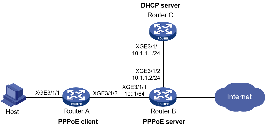
Procedure
1. Configure Router C (DHCP server):
# Enable DHCP.
<RouterC> system-view
[RouterC] dhcp enable
# Configure IP pool pool1 to assign IP addresses and other configuration parameters to clients on subnet 2.2.2.0/24.
[RouterC] ip pool pool1
[RouterC-ip-pool-pool1] network 1.1.1.0 24
[RouterC-ip-pool-pool1] gateway-list 1.1.1.1
[RouterC-ip-pool-pool1] dns-list 8.8.8.8
# Exclude the gateway address from dynamic allocation.
[RouterC-ip-pool-pool1] forbidden-ip 1.1.1.1
[RouterC-ip-pool-pool1] quit
# Configure the default route to the PPPoE server.
[RouterC] ip route-static 0.0.0.0 0 10.1.1.2
2. Configure Router B (PPPoE server):
# Create Virtual-Template 1.
<RouterB> system-view
[RouterB] interface virtual-template 1
# Configure Virtual-Template 1 to use CHAP to authenticate the peer.
[RouterB-Virtual-Template1] ppp authentication-mode chap domain dm1
# Enable Virtual-Template 1 to advertise RA messages.
[RouterB-Virtual-Template1] undo ipv6 nd ra halt
[RouterB-Virtual-Template1] quit
# Enable DHCP.
[RouterB] dhcp enable
# Create a remote BAS IP pool named pool1, and specify the gateway IP address and the network mask for the IP pool. Exclude IP address 1.1.1.1 from dynamic allocation, and specify a DHCP server for the IP pool.
[RouterB] ip pool pool1 bas remote
[RouterB-ip-pool-pool1] gateway 1.1.1.1 24
[RouterB-ip-pool-pool1] forbidden-ip 1.1.1.1
[RouterB-ip-pool-pool1] remote-server 10.1.1.1
[RouterB-ip-pool-pool1] quit
# Configure Ten-GigabitEthernet 3/1/1 to automatically generate an IPv6 link-local address.
[RouterB] interface ten-gigabitethernet 3/1/1
[RouterB-Ten-GigabitEthernet3/1/1] ipv6 address auto link-local
# Enable Ten-GigabitEthernet 3/1/1 to advertise RA messages.
[RouterB-Ten-GigabitEthernet3/1/1] undo ipv6 nd ra halt
# Enable the DHCP relay agent on Ten-GigabitEthernet 3/1/1.
[RouterB-Ten-GigabitEthernet3/1/1] dhcp select relay
# Enable the DHCPv6 server on Ten-GigabitEthernet 3/1/1.
[RouterB-Ten-GigabitEthernet3/1/1] ipv6 dhcp select server
# Enable the PPPoE sever on Ten-GigabitEthernet 3/1/1, and bind the interface to Virtual-Template 1.
[RouterB-Ten-GigabitEthernet3/1/1] pppoe-server bind virtual-template 1
[RouterB-Ten-GigabitEthernet3/1/1] quit
# (For NDRA) Create DHCPv6 prefix pool 1, and specify the prefix 10::/32 with the assigned prefix length 64. Prefix pool 1 contains 4294967296 prefixes from 10::/64 to 10:0:FFFF:FFFF::/64.
[RouterB] ipv6 dhcp prefix-pool 1 prefix 10::/32 assign-len 64
# Create an IPv6 address pool named ndra and apply prefix pool 1 to the IPv6 address pool.
[RouterB] ipv6 pool ndra
[RouterB-ipv6-pool-ndra] prefix-pool 1 export-route
[RouterB-ipv6-pool-ndra] quit
# (For IA_PD) Create prefix pool 6, and specify prefix 20::/32 with assigned prefix length 42.
[RouterB] ipv6 dhcp prefix-pool 6 prefix 20::/32 assign-len 42
# Create IPv6 address pool iapd, and apply prefix pool 6 to address pool iapd.
[RouterB] ipv6 pool iapd
[RouterB-ipv6-pool-iapd] prefix-pool 6 export-route
[RouterB-ipv6-pool-iapd] quit
# Configure a PPPoE user.
[RouterB] local-user user1 class network
[RouterB-luser-network-user1] password simple 123456TESTplat&!
[RouterB-luser-network-user1] service-type ppp
[RouterB-luser-network-user1] quit
# In the ISP domain dm1, perform local AAA for PPP users, and authorize an IPv4 address pool, ND prefix pool, IPv6 DNS address, and IPv6 address pool to PPP users.
[RouterB] domain name dm1
[RouterB-isp-dm1] authentication ppp local
[RouterB-isp-dm1] accounting ppp local
[RouterB-isp-dm1] authorization ppp local
[RouterB-isp-dm1] authorization-attribute ip-pool pool1
[RouterB-isp-dm1] authorization-attribute ipv6-nd-prefix-pool ndra
[RouterB-isp-dm1] authorization-attribute primary-dns ipv6 8::8
[RouterB-isp-dm1] authorization-attribute ipv6-pool iapd
[RouterB-isp-dm1] quit
3. Configure Router A (PPPoE client):
|
|
IMPORTANT: · The device (Router B in this example) can only act as a PPPoE server, and cannot act as a PPPoE client. · The configuration for the device acting as the PPPoE client varies by version. The configuration in this section is for reference only. For more information, see the manual for the device acting as the PPPoE client. |
# Enable bundle DDR on interface Dialer 1.
<RouterA> system-view
[RouterA] interface dialer 1
[RouterA-Dialer1] dialer bundle enable
# On Dialer 1, configure the CHAP username and password sent from Router A to Router B as user1 and 123456TESTplat&! when Router A is authenticated by Router B by using CHAP.
[RouterA-Dialer1] ppp chap user user1
[RouterA-Dialer1] ppp chap password simple 123456TESTplat&!
# Configure the PPPoE session to operate in permanent mode.
[RouterA-Dialer1] dialer timer idle 0
# Set the DDR auto-dial interval to 60 seconds.
[RouterA-Dialer1] dialer timer autodial 60
# (For IPv4) Configure Dialer 1 to obtain an IP address through PPP negotiation, enable Dialer 1 to actively request the DNS server IP address from its peer, and configure Dialer 1 to accept the DNS server IP addresses assigned by the peer even though it does not request DNS server IP addresses from the peer.
[RouterA-Dialer1] ip address ppp-negotiate
[RouterA-Dialer1] ppp ipcp dns request
[RouterA-Dialer1] ppp ipcp dns admit-any
# (For IPv4) Translate the source addresses of the packets from internal hosts into the IP address of Dialer 1.
[RouterA-Dialer1] nat outbound
# (For NDRA) Configure Dialer 1 to automatically generate an IPv6 global unicast address.
[RouterA-Dialer1] ipv6 address auto
# (For IA_PD) Configure Dialer 1 to use DHCPv6 to obtain an IPv6 address and other configuration parameters.
[RouterA-Dialer1] ipv6 address dhcp-alloc
# (For IA_PD) Configure Dialer 1 as a DHCPv6 client for IPv6 prefix acquisition. Configure the DHCPv6 client to assign ID 1 to the obtained IPv6 prefix.
[RouterA-Dialer1] ipv6 dhcp client pd 1
[RouterA-Dialer1] quit
# Configure a PPPoE session corresponding to Dialer bundle 1, which corresponds to Dialer 1.
[RouterA] interface ten-gigabitethernet 3/1/2
[RouterA-Ten-GigabitEthernet3/1/2] pppoe-client dial-bundle-number 1
[RouterA-Ten-GigabitEthernet3/1/2] quit
# Configure default routes.
[RouterA] ip route-static 0.0.0.0 0 dialer 1
[RouterA] ipv6 route-static :: 0 dialer 1
# Enable DHCP.
[RouterA] dhcp enable
# Configure IP address pool pool1 to assign IPv4 addresses and other configuration parameters to clients on subnet 192.168.1.0/24.
[RouterA] ip pool pool1
[RouterA-ip-pool-pool1] network 192.168.1.0 24
[RouterA-ip-pool-pool1] gateway-list 192.168.1.1
[RouterA-ip-pool-pool1] dns-list 8.8.8.8
# Exclude the gateway address from dynamic allocation.
[RouterA-ip-pool-pool1] forbidden-ip 192.168.1.1
[RouterA-ip-pool-pool1] quit
# Assign IP address 192.168.1.1 to Ten-GigabitEthernet3/1/1.
[RouterA] interface ten-gigabitethernet 3/1/1
[RouterA-Ten-GigabitEthernet3/1/1] ip address 192.168.1.1 24
# Enable Ten-GigabitEthernet3/1/1 to advertise RA messages.
[RouterA-Ten-GigabitEthernet3/1/1] undo ipv6 nd ra halt
# Configure Ten-GigabitEthernet3/1/1 to dynamically obtain IPv6 prefix 1, use IPv6 prefix 1 to generate IPv6 address 20::123:1:1 (which must be configured as the gateway for users attached to Router A), and advertise IPv6 prefix 1 to endpoints through RA messages.
[RouterA-Ten-GigabitEthernet3/1/1] ipv6 address 1 123::123:1:1/64
[RouterA-Ten-GigabitEthernet3/1/1] quit
Verifying the configuration
# Verify that Router B has assigned a prefix to Router A through DHCPv6. After Router A is configured and accesses Router B through username user1 and password 123456TESTplat&! through PPPoE, Router B automatically obtains an IPv4 address through DHCPv4 and generates an IPv6 global unicast address through the authorized IPv6 prefix and IPv6 interface identifier obtained through IPv6CP negotiation.
[RouterB] display access-user interface ten-gigabitethernet 3/1/1
UserID Interface IP address MAC address S-/C-VLAN
Username Access type
IPv6 address
0x6 XGE3/1/1 1.1.1.2 001b-21a8-0949 -/-
user1 PPPoE
10::F85B:7EE1:1410:74C9
# Verify that Router B has assigned a prefix to Router A through DHCPv6.
[RouterB] display ipv6 dhcp server pd-in-use
Pool: iapd
IPv6 prefix Type Lease expiration
20::/42 Auto(C) Jul 10 19:45:01 2019
Pool: ndra
IPv6 prefix Type Lease expiration
10::/64 Auto(C) Expires after 2100
# Display information about prefixes on Router A.
[RouterA] display ipv6 prefix
Number Prefix Type
1 20::/42 Dynamic
The output shows that Router A has created prefix 1 based on the ipv6 dhcp client pd 1 command after obtaining a prefix from Router B.
Then, Router A can assign the prefix 20::/42 to the host who uses the prefix to generate an IPv6 global unicast address.
Example: Configuring the PPPoE server to assign IPv6 addresses through the IA_NA+IA_PD method
Network configuration
As shown in Figure 27, configure the PPPoE server as follows:
· Configure the PPPoE server to assign an IPv6 global unicast address to the WAN interface (Dialer 1 in this example) of Router A.
· Configure the PPPoE server to assign a prefix to Router A through IA_PD. Router A then assigns the prefix to the host for it to generate an IPv6 address.

Procedure
1. Configure Router B (PPPoE server):
# Create Virtual-Template 1.
<RouterB> system-view
[RouterB] interface virtual-template 1
# Configure Virtual-Template 1 to use CHAP to authenticate the peer.
[RouterB-Virtual-Template1] ppp authentication-mode chap domain dm1
# Enable Virtual-Template 1 to advertise RA messages.
[RouterB-Virtual-Template1] undo ipv6 nd ra halt
# Set the managed address configuration flag (M) to 1 in RA advertisements to be sent.
[RouterB-Virtual-Template1] ipv6 nd autoconfig managed-address-flag
# Set the other stateful configuration flag (O) to 1 in RA advertisements to be sent on Virtual-Template 1.
[RouterB-Virtual-Template1] ipv6 nd autoconfig other-flag
[RouterB-Virtual-Template1] quit
# Configure Ten-GigabitEthernet 3/1/1 to automatically generate an IPv6 link-local address.
[Router] interface ten-gigabitethernet 3/1/1
[RouterB-Ten-GigabitEthernet3/1/1] ipv6 address auto link-local
# Enable Ten-GigabitEthernet 3/1/1 to advertise RA messages.
[RouterB-Ten-GigabitEthernet3/1/1] undo ipv6 nd ra halt
# Enable the DHCPv6 server on Ten-GigabitEthernet 3/1/1.
[RouterB-Ten-GigabitEthernet3/1/1] ipv6 dhcp select server
# Enable the PPPoE sever on Ten-GigabitEthernet 3/1/1, and bind the interface to Virtual-Template 1.
[RouterB-Ten-GigabitEthernet3/1/1] pppoe-server bind virtual-template 1
[RouterB-Ten-GigabitEthernet3/1/1] quit
# (For IA_PD) Create prefix pool 6, and specify prefix 20::/32 with assigned prefix length 42.
[RouterB] ipv6 dhcp prefix-pool 6 prefix 20::/32 assign-len 42
# Create an IPv6 address pool named pool1.
[RouterB] ipv6 pool pool1
# (For IA_NA) Configure IPv6 address pool pool1 with network 1::/32 for dynamic allocation and DNS server IP address 8::8.
[RouterB-ipv6-pool-pool1] network 1::/32
[RouterB-ipv6-pool-pool1] dns-server 8::8
# (For IA_PD) Apply prefix pool 6 to address pool pool1.
[RouterB-ipv6-pool-pool1] prefix-pool 6 export-route
[RouterB-ipv6-pool-pool1] quit
# Configure a PPPoE user.
[RouterB] local-user user1 class network
[RouterB-luser-network-user1] password simple 123456TESTplat&!
[RouterB-luser-network-user1] service-type ppp
[RouterB-luser-network-user1] quit
# In the ISP domain dm1, perform local AAA for PPP users, and authorize an address pool to PPP users.
[RouterB] domain name dm1
[RouterB-isp-dm1] authentication ppp local
[RouterB-isp-dm1] accounting ppp local
[RouterB-isp-dm1] authorization ppp local
[RouterB-isp-dm1] authorization-attribute ipv6-pool pool1
[RouterB-isp-dm1] quit
2. Configure Router A (PPPoE client):
|
|
IMPORTANT: · The device (Router B in this example) can only act as a PPPoE server, and cannot act as a PPPoE client. · The configuration for the device acting as the PPPoE client varies by version. The configuration in this section is for reference only. For more information, see the manual for the device acting as the PPPoE client. |
# Enable bundle DDR on interface Dialer 1.
<RouterA> system-view
[RouterA] interface dialer 1
[RouterA-Dialer1] dialer bundle enable
# On Dialer 1, configure the CHAP username and password sent from Router A to Router B as user1 and 123456TESTplat&! when Router A is authenticated by Router B by using CHAP.
[RouterA-Dialer1] ppp chap user user1
[RouterA-Dialer1] ppp chap password simple 123456TESTplat&!
# Configure the PPPoE session to operate in permanent mode.
[RouterA-Dialer1] dialer timer idle 0
# Set the DDR auto-dial interval to 60 seconds.
[RouterA-Dialer1] dialer timer autodial 60
# (For IA_NA+IA_PD) Configure Dialer 1 to use DHCPv6 to obtain an IPv6 address and other configuration parameters.
[RouterA-Dialer1] ipv6 address dhcp-alloc
# (For IA_PD) Configure Dialer 1 as a DHCPv6 client for IPv6 prefix acquisition. Configure the DHCPv6 client to assign ID 1 to the obtained IPv6 prefix.
[RouterA-Dialer1] ipv6 dhcp client pd 1
[RouterA-Dialer1] quit
# Configure a PPPoE session corresponding to Dialer bundle 1, which corresponds to Dialer 1.
[RouterA] interface ten-gigabitethernet 3/1/2
[RouterA-Ten-GigabitEthernet3/1/2] pppoe-client dial-bundle-number 1
[RouterA-Ten-GigabitEthernet3/1/2] quit
# Configure a default route.
[RouterA] ipv6 route-static :: 0 dialer 1
# Enable Ten-GigabitEthernet3/1/1 to advertise RA messages.
[RouterA] interface ten-gigabitethernet 3/1/1
[RouterA-Ten-GigabitEthernet3/1/1] undo ipv6 nd ra halt
# Configure Ten-GigabitEthernet3/1/1 to dynamically obtain IPv6 prefix 1, use IPv6 prefix 1 to generate IPv6 address 20::123:1:1 (which must be configured as the gateway for users attached to Router A), and advertise IPv6 prefix 1 to endpoints through RA messages.
[RouterA-Ten-GigabitEthernet3/1/1] ipv6 address 1 123::123:1:1/64
[RouterA-Ten-GigabitEthernet3/1/1] quit
Verifying the configuration
# Verify that Router B has assigned an IPv6 global unicast address to Router A through DHCPv6 after Router A is configured and accesses Router B through username user1 and password 123456TESTplat&! through PPPoE.
[Router] display access-user interface ten-gigabitethernet 3/1/1
UserID Interface IP address MAC address S-/C-VLAN
Username Access type
IPv6 address
0x9 XGE3/1/1 - 001b-21a8-0949 -/-
user1 PPPoE
1::1
# Verify that Router B has assigned a prefix to Router A through DHCPv6.
[RouterB] display ipv6 dhcp server pd-in-use
Pool: pool1
IPv6 prefix Type Lease expiration
20::/42 Auto(C) Jul 10 19:45:01 2019
# Display information about prefixes on Router A.
[RouterA] display ipv6 prefix
Number Prefix Type
1 20::/42 Dynamic
The output shows that Router A has created prefix 1 based on the ipv6 dhcp client pd 1 command after obtaining a prefix from Router B.
Then, Router A can assign the prefix 20::/42 to the host who uses the prefix to generate an IPv6 global unicast address.
Example: Assigning IP addresses to dual-stack users through the local DHCP server
Network configuration
As shown in Figure 28, configure the PPPoE server as a DHCP server to assign an IPv4 address to the host and configure it as a DHCPv6 server to assign an IPv6 address to the host.

Procedure
# Configure Virtual-Template 1 to use CHAP for authentication.
<Router> system-view
[Router] interface virtual-template 1
[Router-Virtual-Template1] ppp authentication-mode chap domain dm1
# Enable Virtual-Template 1 to advertise RA messages.
[Router-Virtual-Template1] undo ipv6 nd ra halt
# Set the managed address configuration flag (M) to 1 in RA advertisements to be sent.
[Router-Virtual-Template1] ipv6 nd autoconfig managed-address-flag
# Set the other stateful configuration flag (O) to 1 in RA advertisements to be sent on Virtual-Template 1.
[Router-Virtual-Template1] ipv6 nd autoconfig other-flag
[Router-Virtual-Template1] quit
# Configure Ten-GigabitEthernet 3/1/1 to automatically generate an IPv6 link-local address.
[Router] interface ten-gigabitethernet 3/1/1
[Router-Ten-GigabitEthernet3/1/1] ipv6 address auto link-local
# Enable Ten-GigabitEthernet 3/1/1 to advertise RA messages.
[Router-Ten-GigabitEthernet3/1/1] undo ipv6 nd ra halt
# Enable the DHCPv6 server on Ten-GigabitEthernet 3/1/1.
[Router-Ten-GigabitEthernet3/1/1] ipv6 dhcp select server
# Enable the PPPoE server on Ten-GigabitEthernet 3/1/1, and bind the interface to Virtual-Template 1.
[Router-Ten-GigabitEthernet3/1/1] pppoe-server bind virtual-template 1
[Router-Ten-GigabitEthernet3/1/1] quit
# Enable DHCPv4.
[Router] dhcp enable
# Configure local BAS IP address pool pool1.
[Router] ip pool pool1 bas local
[Router-ip-pool-pool1] gateway 1.1.1.1 24
[Router-ip-pool-pool1] dns-list 8.8.8.8
# Exclude the IP address 1.1.1.1 from dynamic allocation in IP address pool pool1.
[Router-ip-pool-pool1] forbidden-ip 1.1.1.1
[Router-ip-pool-pool1] quit
# Configure IPv6 address pool pool1 with network 1::/32 for dynamic allocation and DNS server IP address 8::8.
[Router] ipv6 pool pool1
[Router-ipv6-pool-pool1] network 1::/32 export-route
[Router-ipv6-pool-pool1] dns-server 8::8
[Router-ipv6-pool-pool1] quit
# Create a PPPoE user.
[Router] local-user user1 class network
[Router-luser-network-user1] password simple 123456TESTplat&!
[Router-luser-network-user1] service-type ppp
[Router-luser-network-user1] quit
# In the ISP domain dm1, perform local AAA for PPP users, and authorize address pools to PPP users.
[Router] domain name dm1
[Router-isp-dm1] authentication ppp local
[Router-isp-dm1] accounting ppp local
[Router-isp-dm1] authorization ppp local
[Router-isp-dm1] authorization-attribute ipv6-pool pool1
[Router-isp-dm1] authorization-attribute ipv6-pool pool1
[Router-isp-dm1] quit
Verifying the configuration
# Log in to the router by using username user1 and password 123456TESTplat&!.
# Display information about IP addresses assigned by the DHCP server.
[Router] display access-user interface Ten-GigabitEthernet 3/1/1
UserID Interface IP address MAC address S-/C-VLAN
Username Access type
IPv6 address
0xc XGE3/1/1 1.1.1.2 001b-21a8-0949 -/-
user1 PPPoE
1::1
The output shows that the router has assigned an IPv4 address and an IPv6 address to the host.
Example: Configuring PPPoE server RADIUS-based IP address assignment
Network configuration
As shown in Figure 29, configure the PPPoE server to meet the following requirements:
· The PPPoE server uses the RADIUS server to perform authentication, authorization, and accounting for access users. This example uses Free RADIUS that runs in the Linux operating system.
· The RADIUS server assigns access users an IP address pool named pool1 and a VPN instance named vpn1.
· Users in vpn1 obtain IP addresses from IP address pool pool1.
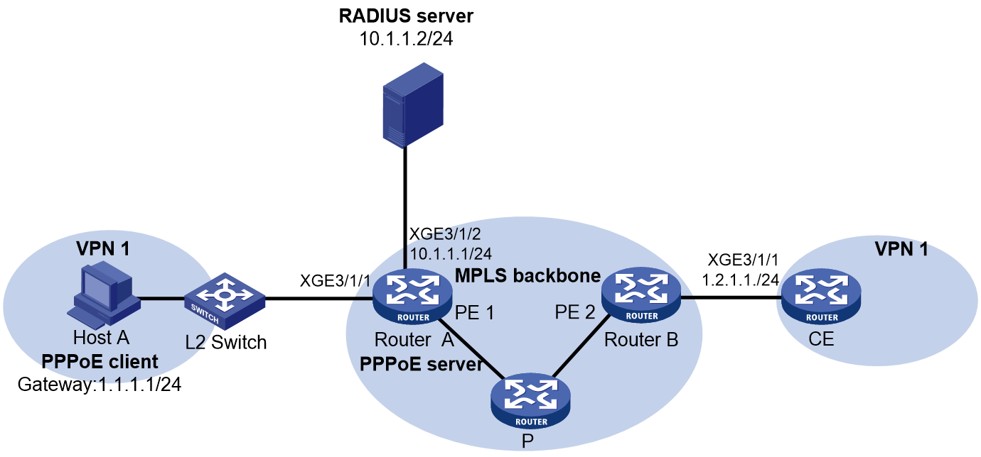
Prerequisites
For the two ends of VPN 1 to communicate with each other, specify the same route target attributes on the two PEs (Router A and Router B). This example describes only the authentication-related configuration on the PE that is connected to the PPPoE client. For information about configuring MPLS L3VPN, see MPLS Configuration Guide.
Procedure
1. Configure the RADIUS server:
# Add the following text to the client.conf file to configure RADIUS client information.
client 10.1.1.1/24 {
secret = radius
}
Where, secret represents the shared key for authentication, authorization, and accounting.
# Add the following text to the users.conf file to configure legal user information.
user1 Auth-Type == CHAP,User-Password := pass1
Service-Type = Framed-User,
Framed-Protocol = PPP,
Framed-Pool = "pool1",
H3C-VPN-Instance = "vpn1",
2. Configure Router A:
a. Configure the PPPoE server:
# Configure Virtual-Template 1 to use CHAP for authentication and use ISP domain dm1 as the authentication domain.
<RouterA> system-view
[RouterA] interface virtual-template 1
[RouterA-Virtual-Template1] ppp authentication-mode chap domain dm1
[RouterA-Virtual-Template1] quit
# Enable DHCP.
[RouterA] dhcp enable
# Configure local BAS IP address pool pool1.
[RouterA] ip pool pool1 bas local
[RouterA-ip-pool-pool1] vpn-instance vpn1
[RouterA-ip-pool-pool1] gateway 1.1.1.1 24
[RouterA-ip-pool-pool1] dns-list 8.8.8.8
# Exclude IP address 1.1.1.1 from dynamic allocation in the address pool.
[RouterA-ip-pool-pool1] forbidden-ip 1.1.1.1
[RouterA-ip-pool-pool1] quit
# Enable the PPPoE server on Ten-GigabitEthernet 3/1/1, and bind the interface to Virtual-Template 1.
[RouterA] interface ten-gigabitethernet 3/1/1
[RouterA-Ten-GigabitEthernet3/1/1] pppoe-server bind virtual-template 1
[RouterA-Ten-GigabitEthernet3/1/1] quit
b. Configure a RADIUS scheme:
# Create a RADIUS scheme named rs1, and enter its view.
[RouterA] radius scheme rs1
# Specify the primary authentication server and the primary accounting server.
[RouterA-radius-rs1] primary authentication 10.1.1.2
[RouterA-radius-rs1] primary accounting 10.1.1.2
# Set the shared key for secure communication with the server to radius in plain text.
[RouterA-radius-rs1] key authentication simple radius
[RouterA-radius-rs1] key accounting simple radius
# Exclude domain names in the usernames sent to the RADIUS server.
[RouterA-radius-rs1] user-name-format without-domain
[RouterA-radius-rs1] quit
c. Configure an authentication domain:
# Create an ISP domain named dm1.
[RouterA] domain name dm1
# In ISP domain dm1, perform RADIUS authentication, authorization, and accounting for users based on scheme rs1.
[RouterA-isp-dm1] authentication ppp radius-scheme rs1
[RouterA-isp-dm1] authorization ppp radius-scheme rs1
[RouterA-isp-dm1] accounting ppp radius-scheme rs1
[RouterA-isp-dm1] quit
Verifying the configuration
# Verify that Host A can successfully ping CE. (Details not shown.)
# Display binding information about assigned IP addresses in VPN1.
[RouterA] display dhcp server ip-in-use vpn-instance vpn1
IP address Client identifier/ Lease expiration Type
Hardware address
1.1.1.2 3030-3030-2e30-3030- Unlimited Auto(C)
662e-3030-3033-2d45-
7468-6572-6e65-74
Example: Configuring PPPoE agency (unified PPPoE agency mode+authorizing a remote BAS IP address pool)
Network configuration
Campus users act as DHCP clients and access the campus BRAS in IPoE mode through a Layer 2 network. The campus BRAS is connected to the ISP BRAS to perform PPPoE agency for external network traffic of campus users. When a campus user accesses the external network, the campus BRAS simulates a PPPoE client to initiate dialup requests for network access to the ISP BRAS acting as the PPPoE server.
· For the internal network traffic:
¡ Enable IPoE on Ten-GigabitEthernet 3/1/2 on the campus BRAS to provide the BRAS access service for campus users.
¡ A DHCP server allocates IPv4 addresses to campus users.
¡ A server acts as both the AAA server and Web server.
¡ After a DHCP client is abnormally logged out, the user can come online again through IPv4 packet initiation.
· For the external network traffic:
¡ Enable PPPoE agency on Ten-GigabitEthernet 3/1/3 of the campus BRAS. When a campus user needs to access the external network, the campus BRAS provides the agency service for the user. After the agency is performed successfully for the user, the user can access the specified ISP network.
Figure 30 Network diagram
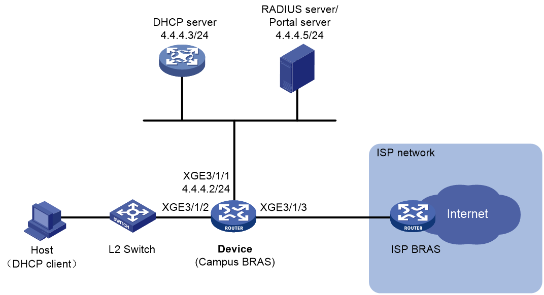
Prerequisites
Configure IP addresses for interfaces, and make sure devices can reach each other at Layer 3. (Details not shown.)
Configure the AAA server and Web server correctly. (Details not shown.)
Restrictions and guidelines
For a campus user, you must open an ISP account, and bind the internal network account of the campus user to the opened ISP account and PPPoE agency group name of the ISP. Then, a campus user can trigger the agency process and pass the PPPoE authentication of the ISP after coming online.
Procedure
1. Configure the DHCP server:
# Enable DHCP globally.
<DHCP-server> system-view
[DHCP-server] dhcp enable
# Create address pool pool1 and enter its view.
[DHCP-server] ip pool pool1
# Specify primary subnet 3.3.3.0/24 for dynamic allocation in the address pool.
[DHCP-server-ip-pool-pool1] network 3.3.3.0 24
# Specify gateway address 3.3.3.1.
[DHCP-server-ip-pool-pool1] gateway-list 3.3.3.1
# Exclude IP address 3.3.3.1 from dynamic allocation.
[DHCP-server-ip-pool-pool1] forbidden-ip 3.3.3.1
[DHCP-server-ip-pool-pool1] quit
# Configure the default route.
[DHCP-server] ip route-static 0.0.0.0 0 4.4.4.2
2. Configure Device:
a. Configure the DHCP relay agent:
# Enable DHCP globally.
<Device> system-view
[Device] dhcp enable
# Create remote BAS IP address pool pool1, and specify the gateway address, excluded IP address, and DHCP server for the address pool.
[Device] ip pool pool1 bas remote
[Device-ip-pool-pool1] gateway 3.3.3.1 24
[Device-ip-pool-pool1] forbidden-ip 3.3.3.1
[Device-ip-pool-pool1] remote-server 4.4.4.3
[Device-ip-pool-pool1] quit
b. Configure a RADIUS scheme:
# Create RADIUS scheme rs1, and enter its view.
[Device] radius scheme rs1
# Configure primary servers and keys for authentication and accounting.
[Device-radius-rs1] primary authentication 4.4.4.5
[Device-radius-rs1] primary accounting 4.4.4.5
[Device-radius-rs1] key authentication simple radius
[Device-radius-rs1] key accounting simple radius
# Send the username to the RADIUS server as the username is entered.
[Device-radius-rs1] user-name-format keep-original
[Device-radius-rs1] quit
c. Configure authentication domains:
# (IPoE preauthentication domain.) Configure authentication domain dm1 as the preauthentication domain for IPoE users.
[Device] domain name dm1
[Device-isp-dm1] authentication ipoe none
[Device-isp-dm1] authorization ipoe none
[Device-isp-dm1] accounting ipoe none
# Configure the authorized address pool and user group in the preauthentication domain.
[Device-isp-dm1] authorization-attribute user-group pre
[Device-isp-dm1] authorization-attribute ip-pool pool1
# Configure the Web authentication page URL and the Web authentication server IP address.
[Device-isp-dm1] web-server url http://4.4.4.5:8080/portal/
[Device-isp-dm1] web-server ip 4.4.4.5
[Device-isp-dm1] quit
# (IPoE postauthentication domain.) Configure authentication domain dm2 as the postauthentication domain for IPoE users.
[Device] domain name dm2
[Device-isp-dm2] authentication ipoe radius-scheme rs1
[Device-isp-dm2] authorization ipoe radius-scheme rs1
[Device-isp-dm2] accounting ipoe radius-scheme rs1
# Configure the authorized PPPoE agency user group in the postauthentication domain.
[Device-isp-dm2] authorization-attribute user-group pppoea
[Device-isp-dm2] quit
# (Authentication domain for PPPoE agency users.) Create ISP domain dm3, and enter its view.
[Device] domain name dm3
# Configure the PPPoE agency users to use RADIUS scheme rs1 for accounting. For PPPoE agency users in the domain, you can configure only the accounting method and cannot configure the authentication or authorization method in the current software version. The system uses the default authentication method (no authentication) and the default authorization method (no authorization) for PPPoE agency users in the domain.
[Device-isp-dm3] accounting pppoea radius-scheme rs1
[Device-isp-dm3] quit
d. Configure IPoE Web authentication.
For more information about configuring IPoE Web authentication, see BRAS Services Configuration Guide.
e. Configure the PPPoE agency:
# Configure advanced IPv4 ACL neiwang_permit with the following rules:
- Configure a rule to match traffic destined to 4.4.4.6. In this example, traffic destined to 4.4.4.6 is internal network traffic. You can modify the destination IP address as needed.
- Configure a rule to match traffic destined to user network segment 3.3.3.0/24, so that users on the same network segment can communicate with each other and the gateway. If you do not configure this rule, this type of traffic will be processed as the external network traffic. As a result, users on the same network segment cannot communicate with each other and the gateway.
[Device] acl advanced name neiwang_permit
[Device-acl-ipv4-adv-neiwang_permit] rule 0 permit ip destination 4.4.4.6 0
[Device-acl-ipv4-adv-neiwang_permit] rule 10 permit ip destination 3.3.3.0 0.0.0.255
[Device-acl-ipv4-adv-neiwang_permit] quit
# Create a PPPoE agency user group named pppoea.
[Device] user-group pppoea
New user group added.
# Configure a PPPoE agency forwarding policy. Traffic matching the specified ACL is considered as the internal network traffic and is directly forwarded. Traffic not matching the specified ACL is considered as the external network traffic and forwarded through the PPPoE agency.
[Device-ugroup-pppoea] pppoe-agency forward ipv4 acl name neiwang_permit
# Configure the authentication domain for PPPoE agency users. The BRAS can initiate PPPoE dialup to the corresponding ISP only after a PPPoE agency user passes authentication and comes online in the domain. The username and password used for authentication can only be deployed through COA messages by the AAA server, and an account must be opened for the campus user in an ISP.
[Device-ugroup-pppoea] pppoe-agency authentication domain dm3
[Device-ugroup-pppoea] quit
# Create VT interface 1.
[Device] interface virtual-template 1
[Device-Virtual-Template1] quit
# Enable the PPPoE agency on Ten-GigabitEthernet 3/1/3. Bind the interface to a PPPoE agency group. The PPPoE agency group name is deployed through COA messages by the AAA server. Suppose the PPPoE agency group name deployed through COA messages is cmcc.
[Device] interface ten-gigabitethernet 3/1/3
[Device–Ten-GigabitEthernet3/1/3] pppoe-agency bind virtual-template 1 pppoe-agency-group cmcc
[Device–Ten-GigabitEthernet3/1/3] quit
# Enable the RADIUS DAE service, and enter RADIUS DAE server view.
[Device] radius dynamic-author server
# Specify the RADIUS DAE client IP address as 4.4.4.5 and configure the shared key as 123456 in plain text.
[Device-radius-da-server] client ip 4.4.4.5 key simple 123456
# Configure the listening port of the server for agency reply packets as 3799 during the PPPoE agency process. This example uses the default port number 3799.
[Device-radius-da-server] pppoe-agency reply-port 3799
[Device-radius-da-server] quit
# Configure the TCP MSS as 1400 bytes (recommended setting).
|
|
NOTE: As a best practice to prevent large packets from being dropped during transmission between campus BRAS and ISP BRAS, which affects network service, use the tcp modify-mss command in system view to set a smaller TCP MSS value. |
[Device] tcp modify-mss 1400
Verifying the configuration
# After a user passes preauthentication, use the following command to view online IPoE user information. The output shows that the user obtains IP address 3.3. 3.2.
[Device] display access-user interface ten-gigabitethernet 3/1/2
UserID Interface IP address MAC address S-/C-VLAN
Username Access type
IPv6 address
0x5c XGE3/1/2 3.3.3.2 000c-29a6-b656 -/-
000c29a6b656 L2 IPoE dynamic
-
# After a user passes preauthentication, enter the username and password on the Web page to complete Web authentication. After the user passes Web authentication, execute the following command to view the online information of the IPoE user.
[Device] display access-user interface ten-gigabitethernet 3/1/2
Username Access type
IPv6 address
0x5c XGE3/1/2 3.3.3.2 000c-29a6-b656 -/-
user1@dm2 Web auth
-
# The AAA server uses a COA message to issue a PPPoE agency request. In the request, the agency group name is cmcc, and the username and password are the account information registered in the ISP. After the user comes online through the PPPoE agency successfully, verify that the user information is as follows.
[Device] display access-user interface ten-gigabitethernet 3/1/3
Username Access type
IPv6 address
0x5d XGE3/1/3 6.0.0.2 000c-29a6-b656 -/-
test PPPoEA
-
Example: Configuring PPPoE agency (ISP-side agency gateway+authorizing a remote BAS IP address pool)
Network configuration
Campus users act as DHCP clients and access the campus BRAS in IPoE mode through a Layer 2 network. The campus BRAS interconnects with the agency gateway, and the agency gateway provides the PPPoE agency service for external network traffic of the campus users. When a campus user needs to access the external network, the traffic is sent from the campus BRAS to the agency gateway. The agency gateway matches the agency user based on traffic information and forwards the traffic to the ISP BRAS through the agency user.
· For the internal network traffic:
¡ Enable IPoE on Ten-GigabitEthernet 3/1/2 on the campus BRAS to provide the BRAS access service for campus users.
¡ A DHCP server allocates IPv4 addresses to campus users.
¡ A server acts as the campus AAA server. After a user comes online on the campus BRAS, the campus BRAS notifies the ISP AAA server of the user information.
¡ After a DHCP client is abnormally logged out, the user can come online again through IPv4 packet initiation.
· For the external network traffic:
¡ A server acts as the ISP AAA server. After a campus user comes online, the ISP AAA server notifies the agency gateway to simulate a PPPoE client to initiate dialup requests for network access to the ISP BRAS acting as the PPPoE server.
¡ Enable the PPPoE agency feature on Ten-GigabitEthernet 3/1/1 of the agency gateway. The agency gateway provides the agency service for the campus users. After the agency is performed successfully for a user, the user can access ISP network.
Figure 31 Network diagram
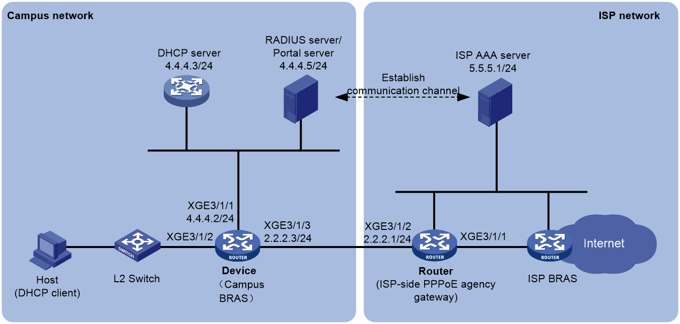
Prerequisites
Configure IP addresses for interfaces, and make sure devices can reach each other at Layer 3.
Properly configure the campus AAA server, ISP AAA server, and ISP BRAS. (Details not shown.)
A communication channel is established between the campus AAA server and the ISP AAA server for transmitting the campus user account information.
Restrictions and guidelines
For a campus user, you must open an ISP account, and bind the internal network account of the campus user to the opened ISP account and PPPoE agency group name of the ISP on the ISP AAA server. Then, a campus user can trigger the agency process and pass the PPPoE authentication by the ISP after coming online.
Procedure
1. Configure the DHCP server:
# Enable DHCP globally.
<DHCP-server> system-view
[DHCP-server] dhcp enable
# Create address pool pool1 and enter its view.
[DHCP-server] ip pool pool1
# Specify primary subnet 3.3.3.0/24 for dynamic allocation in the address pool.
[DHCP-server-ip-pool-pool1] network 3.3.3.0 24
# Specify gateway address 3.3.3.1.
[DHCP-server-ip-pool-pool1] gateway-list 3.3.3.1
# Exclude IP address 3.3.3.1 from dynamic allocation.
[DHCP-server-ip-pool-pool1] forbidden-ip 3.3.3.1
[DHCP-server-ip-pool-pool1] quit
# Configure the default route.
[DHCP-server] ip route-static 0.0.0.0 0 4.4.4.2
2. Configure the campus BRAS:
a. Configure the DHCP relay agent:
# Enable DHCP globally.
<Device> system-view
[Device] dhcp enable
# Create remote BAS IP address pool pool1, and specify the gateway address, excluded IP address, and DHCP server for the address pool.
[Device] ip pool pool1 bas remote
[Device-ip-pool-pool1] gateway 3.3.3.1 24
[Device-ip-pool-pool1] forbidden-ip 3.3.3.1
[Device-ip-pool-pool1] remote-server 4.4.4.3
[Device-ip-pool-pool1] quit
b. Configure a RADIUS scheme:
# Create RADIUS scheme rs1, and enter its view.
[Device] radius scheme rs1
# Configure primary servers and keys for authentication and accounting.
[Device-radius-rs1] primary authentication 4.4.4.5
[Device-radius-rs1] primary accounting 4.4.4.5
[Device-radius-rs1] key authentication simple radius
[Device-radius-rs1] key accounting simple radius
# Send the username to the RADIUS server as the username is entered.
[Device-radius-rs1] user-name-format keep-original
[Device-radius-rs1] quit
c. Configure user groups:
# Create a user group named pre for users in the preauthentication domain.
[Device] user-group pre
New user group added.
[Device-ugroup-pre] quit
# Create a user group named web for users in the postauthentication domain.
[Device] user-group web
New user group added.
[Device-ugroup-web] quit
d. Configure authentication domains:
# (IPoE preauthentication domain.) Configure authentication domain dm1 as the preauthentication domain for IPoE users.
[Device] domain name dm1
[Device-isp-dm1] authentication ipoe none
[Device-isp-dm1] authorization ipoe none
[Device-isp-dm1] accounting ipoe none
# Configure the authorized address pool and user group in the preauthentication domain.
[Device-isp-dm1] authorization-attribute user-group pre
[Device-isp-dm1] authorization-attribute ip-pool pool1
# Configure the Web authentication page URL and the Web authentication server IP address.
[Device-isp-dm1] web-server url http://4.4.4.5:8080/portal/
[Device-isp-dm1] web-server ip 4.4.4.5
[Device-isp-dm1] quit
# (IPoE postauthentication domain.) Configure authentication domain dm2 as the postauthentication domain for IPoE users.
[Device] domain name dm2
[Device-isp-dm2] authentication ipoe radius-scheme rs1
[Device-isp-dm2] authorization ipoe radius-scheme rs1
[Device-isp-dm2] accounting ipoe radius-scheme rs1
# Authorize user group web to the postauthentication domain.
[Device-isp-dm2] authorization-attribute user-group web
[Device-isp-dm2] quit
e. Configure ACLs for the campus BRAS users in the postauthentication domain:
# Configure advanced IPv4 ACL named neiwang with the following rules:
- Configure a rule to match traffic destined to 4.4.4.6. In this example, traffic destined to 4.4.4.6 is internal network traffic. You can modify the destination IP address as needed.
- Configure a rule to match traffic destined to user network segment 3.3.3.0/24, so that users on the same network segment can communicate with each other and the gateway.
[Device] acl advanced name neiwang
[Device-acl-ipv4-adv-neiwang] rule 0 permit ip destination 4.4.4.6 0 user-group web
[Device-acl-ipv4-adv-neiwang] rule 10 permit ip destination 3.3.3.0 0.0.0.255 user-group web
[Device-acl-ipv4-adv-neiwang] quit
# Configure advanced IPv4 ACL named waiwang. Configure a rule to match traffic sourced from user network segment 3.3.3.0/24, so that users on the network segment can access the external network.
[Device] acl advanced name waiwang
[Device-acl-ipv4-adv-waiwang] rule 0 permit ip source 3.3.3.0 0.0.0.255 user-group web
[Device-acl-ipv4-adv-waiwang] quit
f. Configure traffic classes for the campus BRAS users in the postauthentication domain:
# Create a traffic class named neiwang, and use ACL neiwang as the match criterion.
[Device] traffic classifier neiwang operator and
[Device-classifier-neiwang] if-match acl name neiwang
[Device-classifier-neiwang] quit
# Create a traffic class named waiwang, and use ACL waiwang as the match criterion.
[Device] traffic classifier waiwang operator and
[Device-classifier-waiwang] if-match acl name waiwang
[Device-classifier-waiwang] quit
g. Configure traffic behaviors for the campus BRAS users in the postauthentication domain:
# Configure a traffic behavior named neiwang to permit packets.
[Device] traffic behavior neiwang
[Device-behavior-neiwang] filter permit
[Device-behavior-neiwang] free account
[Device-behavior-neiwang] quit
# Configure a traffic behavior named waiwang to redirect packets to next hop 2.2.2.1, the IP address of the agency gateway access interface Ten-GigabitEthernet 3/1/2.
[Device] traffic behavior waiwang
[Device-behavior-waiwang] redirect next-hop 2.2.2.1
[Device-behavior-waiwang] quit
h. Configure QoS policies for the campus BRAS users in the postauthentication domain:
# Configure QoS policy web for the incoming traffic.
[Device] qos policy web
# Associate traffic classes with traffic behaviors. For users in user group web:
Permit packets destined to the internal network server.
Redirect all traffic except the preceding internal network traffic to the agency gateway for processing as external network traffic.
[Device-qospolicy-web] classifier neiwang behavior neiwang
[Device-qospolicy-web] classifier waiwang behavior waiwang
[Device-qospolicy-web] quit
i. Apply the QoS policy for the campus BRAS users in the postauthentication domain.
# Apply QoS policy web to the incoming traffic. To identify whether the QoS policy takes effect, execute the display qos policy global inbound command.
[Device] qos apply policy web global inbound
j. Configure IPoE Web authentication.
For more information about configuring IPoE Web authentication, see “Configuring IPoE."
3. Configure the agency gateway (the ISP determines the agency group name, school-1 in this example):
a. Configure a RADIUS scheme:
# Create RADIUS scheme rs1, and enter its view.
<Router> system-view
[Router] radius scheme rs1
# Configure primary servers and keys for authentication and accounting.
[Router-radius-rs1] primary authentication 5.5.5.1
[Router-radius-rs1] primary accounting 5.5.5.1
[Router-radius-rs1] key authentication simple radius
[Router-radius-rs1] key accounting simple radius
# Send the username to the RADIUS server as the username is entered.
[Router-radius-rs1] user-name-format keep-original
[Router-radius-rs1] quit
b. Configure the default domain:
# Enter the view of the default ISP domain named system.
[Router] domain name system
# Configure the PPPoE agency users to use RADIUS scheme rs1 for accounting. For PPPoE agency users in the domain, you can configure only the accounting method and cannot configure the authentication or authorization method in the current software version. The system uses the default authentication method (no authentication) and the default authorization method (no authorization) for PPPoE agency users in the domain.
[Router-isp-system] accounting pppoea radius-scheme rs1
[Router-isp-system] quit
c. Enable the agency gateway feature.
# Enable the PPPoE agency gateway feature globally.
[Router] pppoe-agency-relay enable
d. Bind the PPPoE agency interface to the ISP's PPPoE agency group school-1:
# Bind the PPPoE agency gateway access interface Ten-GigabitEthernet 3/1/2 to the ISP's PPPoE agency group school-1. Specify the peer IP address as 2.2.2.3, which is located on the campus BRAS.
[Router] pppoe-agency-relay-group school-1 interface ten-gigabitethernet 3/1/2 peer-ip 2.2.2.3
# Create VT interface 1.
[Router] interface virtual-template 1
[Router-Virtual-Template1] quit
# Enable the PPPoE agency on agency interface Ten-GigabitEthernet 3/1/1 and bind the interface to PPPoE agency group school-1.
[Router] interface ten-gigabitethernet 3/1/1
[Router–Ten-GigabitEthernet3/1/1] pppoe-agency bind virtual-template 1 pppoe-agency-group school-1
[Router–Ten-GigabitEthernet3/1/1] quit
# Configure the TCP MSS as 1400 bytes (recommended setting).
|
|
NOTE: As a best practice to prevent large packets from being dropped during transmission between campus BRAS and ISP BRAS, which affects network service, use the tcp modify-mss command in system view to set a smaller TCP MSS value. |
[Router] tcp modify-mss 1400
Verifying the configuration
# After a campus BRAS user passes authentication, execute the following command to view online IPoE users on the campus BRAS. The output shows that the IP address for the user is 3.3.3.2.
[Device] display access-user interface ten-gigabitethernet 3/1/2
Username Access type
IPv6 address
0x5c XGE3/1/2 3.3.3.2 000c-29a6-b656 -/-
000c29a6b656 L2 IPoE dynamic
-
# After a user passes preauthentication, enter the username and password on the Web page to complete Web authentication. After the user passes Web authentication, execute the following command to view the information of the online IPoE users.
[Device] display access-user interface ten-gigabitethernet 3/1/2
Username Access type
IPv6 address
0x5c XGE3/1/2 3.3.3.2 000c-29a6-b656 -/-
user1@dm2 Web auth
-
# After the agency user comes online, verify that the corresponding PPPoEA user exists on the agency gateway. The username and password of the user are the account information opened by the ISP.
[Router] display access-user interface ten-gigabitethernet 3/1/1
Username Access type
IPv6 address
0x5d XGE3/1/1 6.0.0.2 000c-29a6-b656 -/-
test PPPoEA
-
Example: Configuring PPPoE static dual-stack users
Network configuration
Host is manually configured with static IPv4 address 1.1.1.2/24, static IPv6 address 1::021B:21FF:FEA8:0949/64, and static IPv6 DNS server address 8::F85B:7EE1:1410:74C9. Host is connected to Router through an Ethernet interface, and Router acts as the PPPoE server. Configure Host to access Router through PPPoE by using the manually configured static IP addresses.
Figure 32 Network diagram

Restrictions and guidelines
In some operating systems (for example, Windows 7), if the interface ID in the IPv6 global unicast address requested by a DHCPv6 client is different from the interface ID in the link-local address of the DHCPv6 client, Windows 7 will consider the IPv6 global unicast address as unavailable. As a result, the DHCPv6 client cannot use the address as the source address to send packets. Therefore, as a best practice to ensure that the function operates normally, configure the interface ID in a static IPv6 address to be the same as that in the link-local address when configuring the static IPv6 address. For example, the link-local address in this example is FE80::021B:21FF:FEA8:0949, and the static IPv6 address is 1::021B:21FF:FEA8:0949.
Procedure
# Configure Virtual-Template 1 to use CHAP for authenticating the peer.
<Router> system-view
[Router] interface virtual-template 1
[Router-Virtual-Template1] ppp authentication-mode chap domain dm1
# Configure the device to allow a remote user to come online by using a self-configured static IPv4 address and IPv6 address.
[Router-Virtual-Template1] ppp accept remote-ip-address
[Router-Virtual-Template1] ppp accept remote-ipv6-address
# Enable Virtual-Template 1 to advertise RA messages. Set the managed address configuration flag (M) to 1 to prevent the IPv6 static users from coming online through NDRA.
[Router-Virtual-Template1] undo ipv6 nd ra halt
[Router-Virtual-Template1] ipv6 nd autoconfig managed-address-flag
[Router-Virtual-Template1] quit
# Automatically generate a link-local address for Ten-GigabitEthernet 3/1/1.
[Router] interface ten-gigabitethernet 3/1/1
[Router-Ten-GigabitEthernet3/1/1] ipv6 address auto link-local
# Enable the interface to advertise RA messages.
[Router-Ten-GigabitEthernet3/1/1] undo ipv6 nd ra halt
# Disable the DHCPv6 server and DHCPv6 relay agent on the interface to prevent IPv6 static users from coming online through IA_NA. (The default configuration.)
[Router-Ten-GigabitEthernet3/1/1] undo ipv6 dhcp select
# Enable the PPPoE server on Ten-GigabitEthernet 3/1/1 and bind it to Virtual-Template 1.
[Router-Ten-GigabitEthernet3/1/1] pppoe-server bind virtual-template 1
[Router-Ten-GigabitEthernet3/1/1] quit
# Enable DHCPv4.
[Router] dhcp enable
# Configure a local BAS IP address pool pool1.
[Router] ip pool pool1 bas local
[Router-ip-pool-pool1] gateway 1.1.1.1 24
[Router-ip-pool-pool1] dns-list 8.8.8.8
# Exclude gateway IP address 1.1.1.1 and static user IP address 1.1.1.2 from dynamic allocation.
[Router-ip-pool-pool1] forbidden-ip 1.1.1.1
[Router-ip-pool-pool1] forbidden-ip 1.1.1.2
[Router-ip-pool-pool1] quit
# Exclude static user IPv6 address 1::021B:21FF:FEA8:0949 from dynamic allocation.
[Router] ipv6 dhcp server forbidden-address 1::021B:21FF:FEA8:0949
# Configure a PPPoE user.
[Router] local-user user1 class network
[Router-luser-network-user1] password simple 123456TESTplat&!
[Router-luser-network-user1] service-type ppp
[Router-luser-network-user1] quit
# In ISP domain dm1, perform local AAA for users and authorize an address pool.
[Router] domain name dm1
[Router-isp-dm1] authentication ppp local
[Router-isp-dm1] accounting ppp local
[Router-isp-dm1] authorization ppp local
[Router-isp-dm1] authorization-attribute ip-pool pool1
[Router-isp-dm1] quit
Verifying the configuration
After the configuration is completed, Host accesses Router through PPPoE by using username user1 and password 123456TESTplat&!. Verify that Host has come online successfully by using the manually configured static IP addresses.
[Router] display access-user interface ten-gigabitethernet 3/1/1
Username Access type
IPv6 address
0xc XGE3/1/1 1.1.1.2 001b-21a8-0949 -/-
user1 PPPoE
1::021B:21FF:FEA8:0949
