- Table of Contents
- Related Documents
-
| Title | Size | Download |
|---|---|---|
| 03-Cloud cluster configuration | 896.44 KB |
Restrictions and guidelines: Cloud cluster configuration
Physical cluster working mechanism
Basic concepts of a physical cluster
Connectivity topology of a physical cluster
Physical cluster establishment and changing
Container cluster working mechanism
Basic concepts of a container cluster
Connectivity topology of a container cluster
Container cluster establishment
Container monitoring and intelligent management
Container cluster splitting and MAD
Cloud cluster configuration method
Moving a device from physical cluster A to physical cluster B
Display and maintenance commands for physical clusters
Configuring container cluster MAD
Excluding interfaces from the shutdown action upon detection of multi-active collision
Recovering a container cluster
Optimizing container cluster settings
Enabling software auto-update for software image synchronization
Configuring container cluster bridge MAC persistence
Delaying reporting container cluster link down events
Enabling cloud cluster auto-merge
Isolating the master in the container cluster
Configuring cloud cluster optimization for WLAN access
Verifying and maintaining container clusters
Accessing the container cluster
Cloud cluster configuration examples
Example: Configuring a cloud cluster
Example: Replacing a faulty physical device
Example: Replacing the cluster port when a cluster link fails
Example: Migrating a physical device to another cloud cluster
Configuring a cloud cluster
About cloud cluster
Cloud cluster is an H3C-proprietary software virtualization technology. It uses the Comware 9 containerized architecture to decouple applications and physical devices as much as possible. A Comware 9-based cloud cluster is divided into the following layers:
· Physical cluster—Indicates a physical cluster at the physical device layer. The core idea of physical clustering is to connect multiple physical devices together and virtualize them into one device after necessary configuration. Using this virtualization technology can integrate hardware resources from multiple devices. On one hand, it enables unified management and allocation of hardware resources from multiple devices, increasing resource utilization and reducing management complexity. On the other hand, it also achieves hardware-level backup, which improves the high reliability of the entire system.
· Container cluster—Indicates a container cluster at the application layer. The core idea of container clustering is to logically connect containers running on physical devices together and virtualize them into one system after necessary configuration. Using this virtualization technology can integrate software processing capabilities from multiple containers. It enables collaborative operation, unified management, and uninterrupted maintenance of multiple containers.
|
|
NOTE: Currently, cloud cluster supports only Comware 9-based container clustering. Unless otherwise specified, the term "container" in this document refers to Comware 9-based containers. |
Networking applications
Basic networking applications
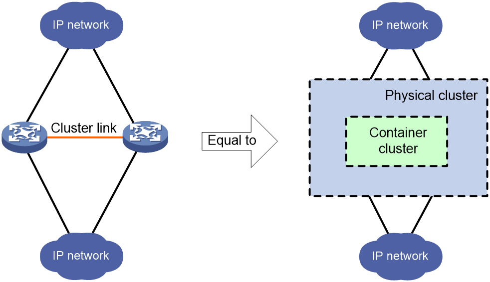
In the basic networking applications of cloud cluster, physical devices have a one-to-one correspondence with Comware containers, with one Comware container running on each physical device. Physical devices can be clustered to form a device-level backup, while Comware containers can be clustered to form a service-level backup. The entire physical cluster corresponds to the Comware container cluster. This provides a simple topology, simple configuration, and easy maintenance.
As shown in Figure 1, two devices form a physical cluster. For their upper and lower layer devices, the two physical devices are virtualized into one network device (corresponding to the container cluster in Figure 1). The virtual network device owns and manages the resources on all its member devices.
Figure 1 Basic networking application of cloud cluster
Advanced networking applications
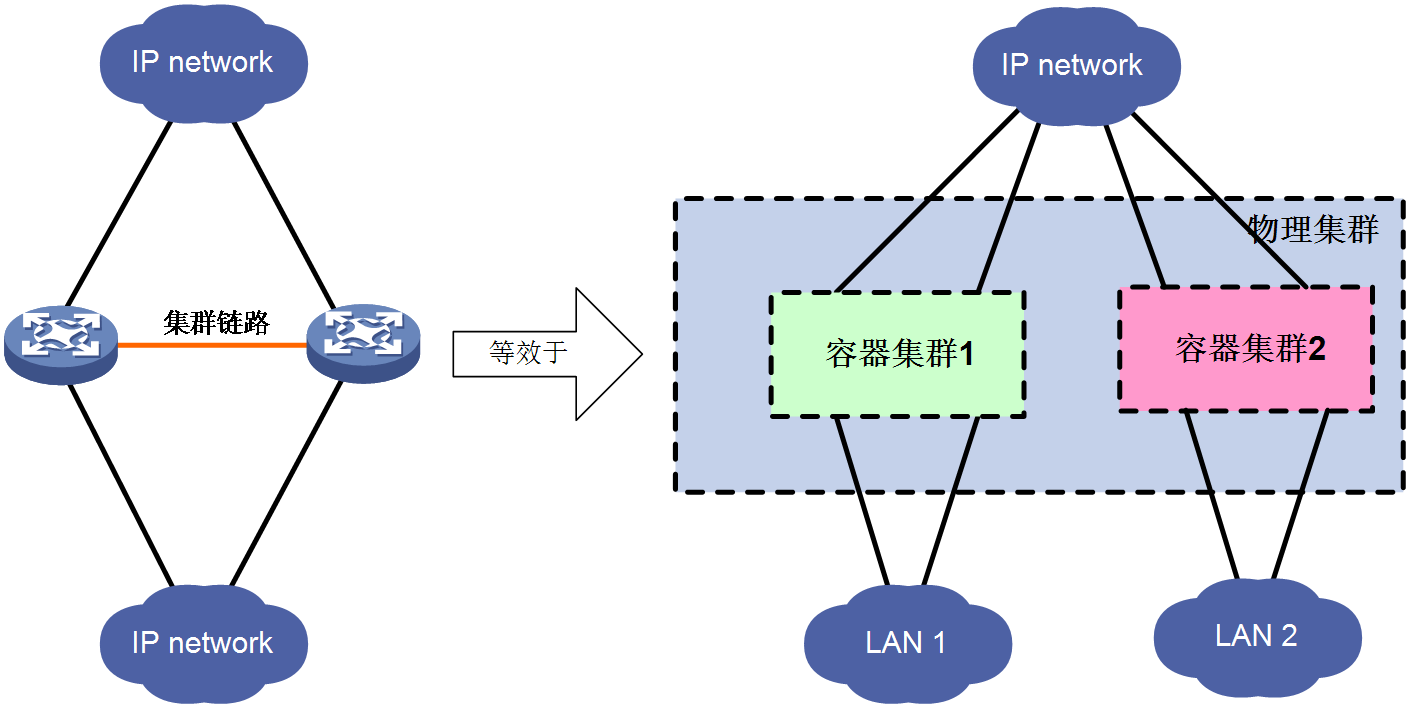
In advanced networking applications of cloud clusters, network administrators can deploy one or more Comware containers on physical devices based on parameters such as performance, hardware resources, and processing capabilities. Comware-based containers created on the same physical cluster can belong to the same cluster, or they can be divided into different clusters to provide services for different user networks.
As shown in Figure 2, two devices form a cloud cluster which, at the physical level, are virtualized into a single physical device. At the service level, they are virtualized into two Comware-based container clusters, providing transmission services for different user networks, respectively. The super administrator of the entire network maintains the physical cluster, while the Comware-based container clusters can be assigned to user network administrators for maintenance. After logging into the Comware-based container clusters, the user network administrators can complete the configuration of features such as switching, routing, and security.
Compared to basic cloud cluster networking applications, advanced cloud cluster networking applications are more flexible and can adapt to personalized management needs of user networks. However, this application has requirements for the performance, hardware resources, and processing capabilities of the physical devices.
Figure 2 Advanced networking application of cloud cluster
Cloud cluster architecture
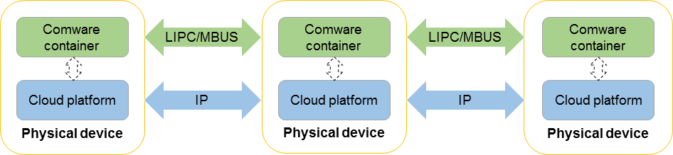
Figure 3 shows the physical architecture of a cloud cluster. The relationship between the physical cluster and the container cluster is as follows:
· Cloud platform modules run on physical devices. Cloud platform modules run directly on the H3C-optimized Linux system. The cloud platform modules on physical devices communicate with each other through Layer 3 channels to virtualize these physical devices into a physical cluster.
· Containers run on cloud platform modules and are managed by cloud platform modules. The containers on physical devices communicate with each other through LIPC/MBUS channels to virtualize containers into a container cluster.
A Comware container is a container that runs the Comware system and provides basic communication functions such as routing and switching for devices. You can also install other containers on devices, but only Comware containers can be virtualized into a container cluster in the current software version.
Figure 3 Physical architecture of a cloud cluster
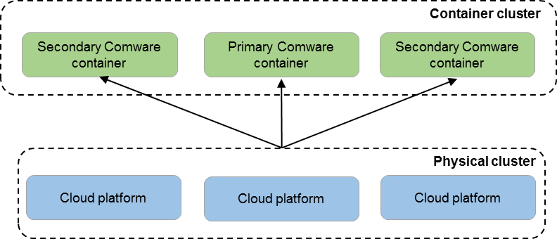
Cloud cluster virtualizes physical devices into a dual-cluster virtualization architecture with a physical cluster and a container cluster, as shown in Figure 4.
Figure 4 Logical architecture of cloud cluster
Benefits
The following are benefits of the overall cloud cluster architecture:
· Dual-layer virtualization architecture—Cloud cluster uses a dual-layer virtual architecture with a physical cluster and a container cluster to separate the underlay hardware infrastructure from the overlay applications. This increases the flexibility of the entire cloud cluster system as follows:
¡ The underlay physical cluster achieves unified management of physical devices, while acting as the orchestration and management platform for the overlay containers.
¡ The overlay container cluster provides high reliability and intelligent elastic scaling for services.
· Dual-layer selection of primary containers—Cloud cluster enhances the stability of service operation by adopting the following dual-layer primary container selection as follow:
¡ When the physical cluster is operating correctly, the primary container in the container cluster is elected and maintained by the physical cluster.
¡ When the physical cluster is operating incorrectly, the container roles are determined by the role election mechanism within the container cluster.
· Simplified management—After the physical cluster is set up, users can log in to the cloud cluster system through any port of any member device to manage all member devices and containers in the cloud cluster.
The following are benefits of the container cluster layer:
· 1:N container backup—The container cluster consists of multiple Comware containers. The primary Comware container is responsible for the operation, management and maintenance of the container cluster and the subordinate Comware containers can also process services as a backup. Once the primary Comware container fails, the system will quickly and automatically elect a new primary Comware container to ensure uninterrupted service operation. This achieves 1:N backup of Comware containers.
· Link aggregation across Comware containers—The physical links between Comware containers and upper and lower layer devices support aggregation. Different physical links on different Comware containers can also be aggregated into a logical link. The physical links can back up for each other or share the traffic load. If a Comware container leaves the container cluster, the links on the other Comware containers can still send and receive packets, thus improving the reliability of the aggregated links.
· Powerful network expansion capabilities—You can increase the number of ports and bandwidth of the container cluster by adding physical devices. In addition, the container cluster can easily and flexibly expand its processing capacity because each member device has CPUs for independently processing protocol packets and forwarding packets.
Restrictions and guidelines: Cloud cluster configuration
If WX3540X or WX3840X requires the EWPXM1XG20 module to expand its AP management capability, make sure both ACs in the cloud cluster are installed with an EWPXM1XG20 module.
In a cloud cluster, to use the map-configuration command to specify the AP configuration file, import the file into the storage media of each member to prevent issues if a master-backup switchover occurs and the AP configuration file cannot be found. The AP configuration file issued by the map-configuration command is effective only on the master of the cloud cluster. You must also specify the storage path on the master as the storage path of the configuration file. For more information about the AP configuration file, see AP Management Configuration Guide.
In a cloud cluster, to use the APDB user script to extend the supported AP models, import the APDB user script into the storage media of each member device to prevent issues if a master-backup switchover occurs and the user script cannot be found. For more information about the APDB user script, see AP Management Configuration Guide.
In a cloud cluster, the following features are not supported on devices:
· Virtual AP (see AP Management Configuration Guide)
· Configuration rollback (see Fundamentals Configuration Guide)
· AP license synchronization (see License Management Configuration Guide)
· NAT (see Network Connectivity Configuration Guide)
· WAPI (see WLAN Security Configuration Guide)
In a cloud cluster, using DPI, Internet access behavior management, or security policies can cause packets to be incorrectly dropped. For more information about DPI, see DPI Configuration Guide. For more information about Internet access behavior management, see Internet Access Behavior Management Configuration Guide. For more information about security policies, see Security Configuration Guide.
Cloud cluster ports do not support the mirroring feature. For more information about mirroring, see Network Management and Monitoring Configuration Guide.
After a master-backup switchover occurs in a cloud cluster, it might take a few minutes for the system to resynchronize data from the cloud platform. During this period, clients cannot access the network through PPSK authentication. For more information about cloud platform PPSK, see WLAN Security Configuration Guide.
Cloud platform components
The components that implement the cloud cluster functionalities within a device are collectively referred to as cloud platform. Cloud platform consists of the following components;
· Cloud platform Manager—Runs in the host operating system of each physical node that participates in the physical cluster management. It is responsible for cloud platform HA functionality, establishing the cluster, and managing cluster members. The following functions are supported:
¡ Managing, establishing, and maintaining the physical cluster, managing cluster members, and generating and updating the cluster topology.
¡ Managing the container cluster. The Manager can intelligently deploy Comware containers based on the distribution of hardware resources in the physical cluster, and elect the primary and subordinate containers for the container cluster.
· Cloud platform Worker—Runs in the host operating system of each physical node. It is responsible for managing the lifecycle of physical nodes and containers. The Worker periodically reports the physical resources and status of the nodes, responds to scheduling instructions from the Manager, and creates and runs containers based on instructions from the Manager.
· Cloud platform Admin—Runs on each physical node. It receives and processes configuration messages from the primary Comware container. The Admin is responsible for managing device operating modes and container description files, and sending requests to the Manager cluster for executing container deployments.
· Cloud platform Agent—Runs in containers. The Agent is responsible for reporting the health status of the services inside the container and notifying the events of the service module cluster and containers.
Figure 5 Cloud platform components
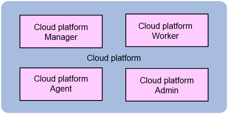
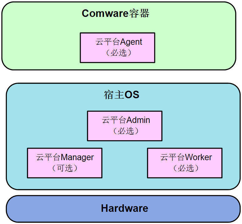
Figure 6 shows the internal running locations of cloud platform components within the device. After each physical device is powered on and starts up, it automatically runs the cloud platform Worker, cloud platform Admin, and cloud platform Agent components. The cloud platform Manager is an optional component. The device will run the cloud platform Manager component only when the device role is configured as manager+worker in order to participate in the management of the physical cluster.
Figure 6 Running locations of cloud platform components
Physical cluster working mechanism
Basic concepts of a physical cluster
Roles of member devices
Every device in the physical cluster is called a member device. Member devices are divided into two roles based on different functions:
· Manager: Responsible for the high availability (HA) function of the cloud platform, establishing and managing the cluster members. It includes the following functions:
¡ Manage the physical cluster, establish and maintain it, manage cluster members, and generate and update cluster topology.
¡ Manage the container cluster, intelligently deploy Comware containers based on the distribution of hardware resources in the physical cluster, and elect the primary and subordinate containers of the container cluster.
Managers are further divided into leader and follower depending on their responsibilities.
¡ Leader: As the primary manager, it is responsible for managing and controlling the entire cloud cluster, acting as the control center of the entire cloud cluster.
¡ Follower: As the backup manager, it is the backup of the leader. It runs as a backup device for the leader while handling business and forwarding messages. When the leader fails, the system automatically elects a new leader from the followers to take over the original leader's work.
When devices are configured as managers, the devices automatically run the manager component to perform the relevant manager functions.
· Worker: Responsible for local node management, reporting node resources to the leader, and receiving scheduling messages from the leader for container deployment.
When devices are configured as workers, the devices automatically run the worker component to perform the relevant worker functions.
At first-time creation of a physical cluster, the network administrator determines the physical devices on which managers are deployed and the leader and follower roles of the physical devices.
Member IDs
In a cloud cluster, a physical device is uniquely identified by a member ID, and member IDs are used during the setup and maintenance of both physical and container clusters.
In a cloud cluster, only one device can use the default member ID, and all other devices must modify their member IDs before joining the cluster. When modifying member IDs, make sure they are unique within the cloud cluster.
· During the setup of a physical cluster, if two devices have the same member ID, the device that registers later cannot join the physical cluster.
· During the operation of a physical cluster, if a new device tries to join but its member ID conflicts with an existing member's ID, the device cannot join the physical cluster.
Member IP addresses
Member IP addresses are used for internal communication within a physical cluster, specifically for exchanging physical cluster protocol messages (which are Layer 3 IP packets). All member devices in the physical cluster must be configured with a member IP address, and all member IP addresses must belong to the same network segment. Make sure all member devices can reach each other at Layer 3.
Join-cluster IP address
Join-cluster IP is an IP address configured by the administrator on a device to guide the device to join the physical cluster. The cluster IP can be the member IP of any existing member device in the physical cluster. As a best practice, configure the member IP of the leader as the join-cluster IP.
During the initial setup of the physical cluster, it is not required to configure the join-cluster for the leader. Devices that have not configured a join-cluster IP consider themselves as the leader.
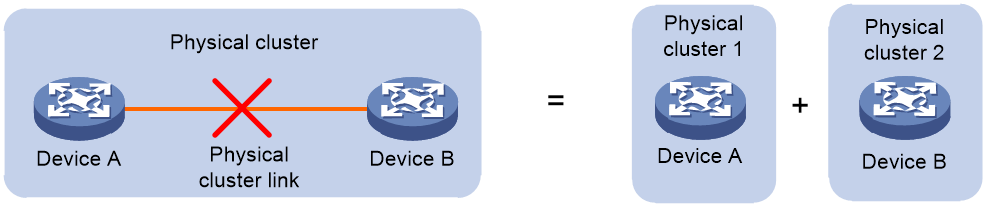
Physical cluster splitting
As shown in Figure 7, after the formation of a physical cluster, if a link failure occurs and results in the two adjacent member devices in the physical cluster becoming disconnected, the physical cluster splits into two separate physical clusters. This process is called physical cluster splitting.
Figure 7 Physical cluster splitting
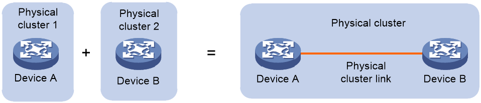
Physical cluster merging
As shown in Figure 8 after the failure link is repaired, the split physical clusters will automatically merge, and this process is called physical cluster merging.
If physical cluster A splits into physical cluster 1 and physical cluster 2, and physical cluster B splits into physical cluster 3 and physical cluster 4, the split clusters will retain the original cluster topology. Therefore, cloud clusters do not allow physical cluster 1 to merge with physical cluster 3 or physical cluster 4, and physical cluster 2 cannot merge with physical cluster 3 or physical cluster 4 either.
Figure 8 Physical cluster merging
Connectivity topology of a physical cluster
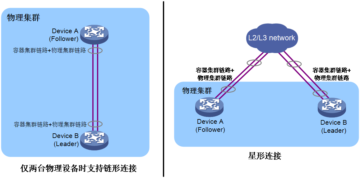
The control packets of a physical cluster are Layer 3 IP packets. The physical cluster requires that member devices be configured in the same network segment and use this network segment to exchange physical cluster control packets. The connectivity topology of the physical cluster is a chain-shaped or star-shaped connection.
· When two devices are set up as a physical cluster, they can be connected in a chain or a star topology.
¡ Chain connections are suitable for networks where member devices are physically concentrated.
¡ Star topology connections have lower physical location requirements for member devices than chain connections and are mainly used for networks where member devices are physically dispersed. However, an intermediary device is required to interconnect the member devices.
· When the number of member devices exceeds two, you must use the star-shaped connection.
Figure 9 Connectivity topology of a physical cluster
|
|
NOTE: Currently, the physical cluster uses the control channel in the container cluster link to transmit physical cluster control packets. To set up a container cluster network, network administrators must use commands to bind the physical interface with the control channel and data channel of the container cluster link on the device. The control channel will be used to transmit physical cluster control packets and container cluster control packets between cloud clusters, while the data channel will be used to transmit data packets for cross-container forwarding. |
Physical cluster establishment and changing
Physical cluster establishment
To initially establish a physical cluster, you must configure devices to determine device identities. When you build the cluster, first complete the cluster planning, including devices to participate in the management of the physical cluster, leader device, member IDs, and network segment used for internal communication within the cluster.
Configure the following parameters for the leader device of the manager role:
· (Optional, default role is Manager+Worker) Device role as Manager+Worker
· (Optional, default values can be used) Member ID
· (Required) Member IP
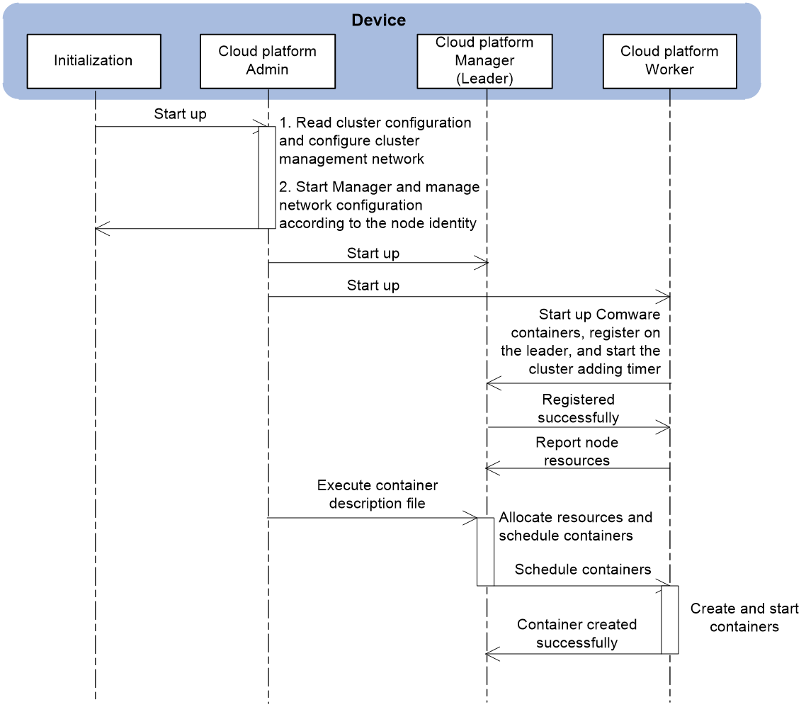
Then, restart the device. The device acts as the leader and operates as the follows:
1. The device starts the Admin, Manager, and Worker components of the cloud platform according to the configuration file.
2. The leader device establishes internal communication channels with worker devices. The worker devices register on the leader and report hardware resource information.
3. The leader notifies the workers to start up containers.
Figure 10 Leader startup process
New device joining in the physical cluster
Newly joined devices in the physical cluster also determine their identities through configuration.
For a follower device of the manager role, you must configure the following parameters:
· (Required) Member ID, must be unique within the cluster.
· (Required) Member IP, must be in the same network segment as the leader's member IP and reachable via routing.
· (Required) Join-cluster IP. As a best practice, specify the leader's member IP as the join-cluster IP. It can also be the member IP of any other member device.
The following steps describe the process of a follower joining the cluster as an example. The startup process for a follower, excluding the manager component, is the same as the startup process for a worker.
After configuring the follower device, restart it and the device will read the configuration. Because the configuration includes the join-cluster IP, the device starts as a follower and sends a cluster join request to the join-cluster IP:
· If the join-cluster IP is the leader's member IP, the leader receives the cluster join request and unicasts a reply indicating a successful join.
· If the join-cluster IP is the member IP of another follower device in the cluster, the follower device forwards the join request to the leader. The leader unicasts a reply indicating a successful join to the new device.
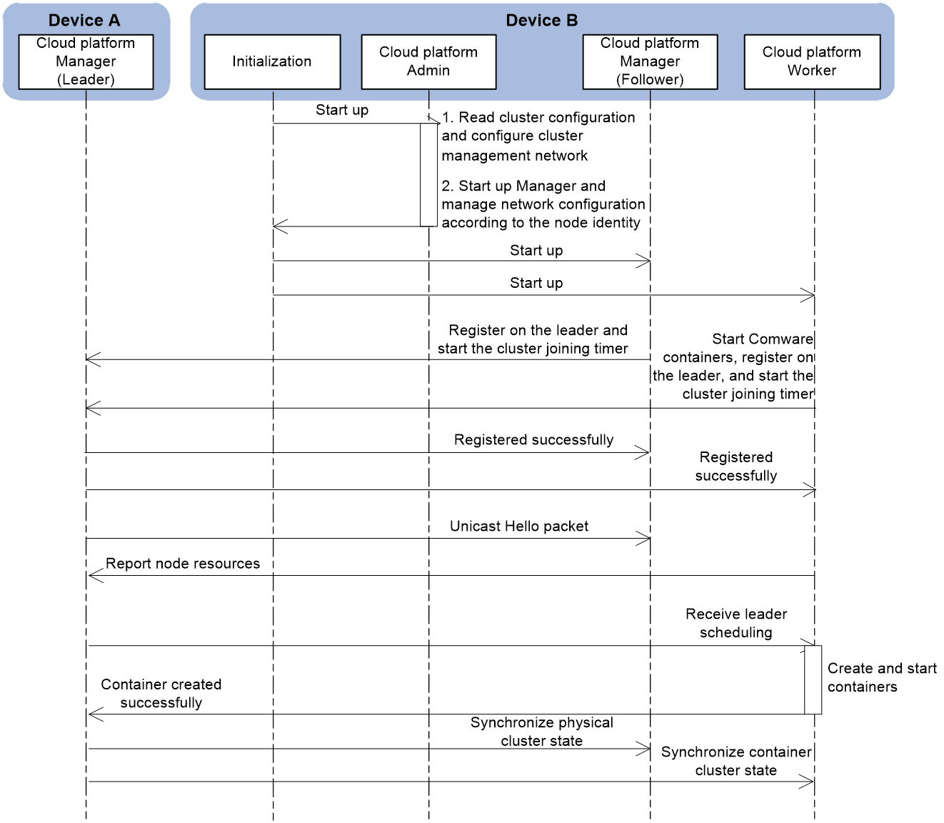
As shown in Figure 11, the startup process of the new device, Device B, joining the physical cluster, Device A is as follows:
1. Device B starts the Admin, Manager, and Worker components of the cloud platform based on the configuration file.
2. The Worker component automatically starts the Comware container, and the Manager (follower) and Worker automatically register with the leader and start the cluster join timer.
3. Device A is the leader in the physical cluster and replies with a successful join message to the Manager (follower) and Worker.
4. The leader periodically unicasts Hello packets (announcing itself as a healthy leader) to the members.
5. After receiving the Hello packet, Device B records the leader's information and reports its local physical resource information to the leader.
6. If the network administrator issues a command to create a container, the leader schedules Device B to create and start the container based on the resource information reported by each member device.
7. After the container on Device B is successfully started, the Worker component reports the container's information to the leader.
8. The leader synchronizes the physical cluster information with the Manager component of Device B so that the follower can act as a backup to the leader. The leader also synchronizes the information about other containers in the current cloud cluster with the Worker component of Device B.
Figure 11 Add a new device to the physical cluster
Member device exiting the physical cluster
After the physical cluster is successfully established, the leader records the information of all managers and workers in the cluster, and draws the cluster topology based on the connection. The relationship between the leader and follower is maintained through interacting Hello packets. A member device can actively leave the physical cluster or be forced to leave the cluster:
· Active leaving
Active leaving refers to the scenario where an administrator executes the undo join-cluster command in cloud-cluster member view to remove the device from the physical cluster. The device sends a leave cluster message to the leader, and the leader replies with a leave cluster response message. Then, the leader removes the device from the physical cluster device list and physical cluster topology. Finally, the updated physical cluster information and cluster topology will be synchronized to other followers.
· Passive leaving
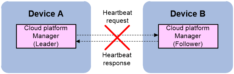
Passive leaving of a member device from the physical cluster refers to the scenario where the member cannot reach the leader's member IP. Control packets cannot reach the other end. The process of a member device passively leaving the physical cluster is as follows:
a. The leader periodically unicasts Hello packets to announce its status to all followers.
b. Each follower locally creates an election timer. If a Hello packet is received before the election timer times out, it is considered that the leader is running normally, and the follower responds with a Hello response packet.
c. When the leader receives a Hello response packet, it considers that the corresponding follower is running normally. If the leader does not receive a Hello response packet from a certain follower, the leader will decrease the number of Hello packet timeouts by 1. If the number of Hello packet timeouts reaches 0 and the leader still has not received a Hello response packet from that follower, the leader considers that the follower has temporarily left the physical cluster and sets the follower's status to Offline.
d. If a follower does not receive a Hello packet from the leader until the election timer times out, it considers that the leader has failed. The follower will enter the leader role election process.
Figure 12 Passive leaving
Physical cluster splitting
During the operation of a physical cluster, leaders, followers, and workers in the cluster periodically send Hello messages to each other to maintain the cluster relationship. If a Hello message times out and one end still has not received a response from the other end, it is considered as a failure and the state of the other end is set to Offline.
Once a physical cluster is formed, if a link fails between member devices and the Hello messages can reach the destination, the physical cluster splits into two separate physical clusters. This process is called cluster splitting. After splitting, the following conditions might occur:
· If after the split, the number of member devices in one physical cluster is greater than half of the total number of member devices before the split, then this physical cluster can function normally. The other physical cluster will not be able to function properly.
· If after the split, the number of member devices in both physical clusters is less than or equal to half of the total number of member devices before the split, then neither of the two physical clusters can function properly.
Working properly means being able to maintain the physical cluster and manage the containers deployed on the physical cluster. Not working properly means being able to maintain the physical cluster but unable to manage the containers deployed on it.
Leader in one cluster
If after the split, the number of member devices in one physical cluster exceeds half of the total number of member devices before the split, then this physical cluster can retain the original Leader or elect a new Leader to continue functioning normally. The other physical cluster, having fewer member devices than half of the pre-split total, cannot retain the original Leader or elect a new Leader, and thus cannot function properly.
As shown in Figure 13, assuming that the total number of member devices before the split is 3, after the split, physical cluster 1 has 2 member devices, and physical cluster 2 has 1 member device.
· Physical cluster 1 has two member devices:
¡ If one of the two member devices in physical cluster 1 was the Leader, then after the split, this Leader will detect through Hello messages that a member device has left. Since two member devices exist in the current physical cluster, which is more than 3/2, the original Leader will continue to act as the Leader and work normally.
¡ If both member devices in physical cluster 1 were Followers, then after the Leader has left, according to the Raft algorithm, one of the two Followers will be elected as the new Leader to replace the original Leader and continue to work normally.
· Physical cluster 2 has only one member device:
¡ If the device was the Leader, then after the split and Hello messages timed out, the Leader detects that the number of member devices in physical cluster 2 is less than 3/2. It will be downgraded to a Follower.
¡ If the device was a Follower, then after the split and the departure of the Leader, according to the Raft algorithm, the device cannot obtain the majority of votes and must continue as a Follower.
Figure 13 Leader in one physical cluster
No leader in either cluster
If after the split, the number of member devices in both physical clusters is less than or equal to half of the total number of member devices before the split, then according to the Raft algorithm, neither of these physical clusters can retain the original Leader nor elect a new Leader. Because both clusters lack a Leader, neither can function properly.
As shown in Figure 14, before the split, the total number of members is 2. After the split, both physical cluster 1 and physical cluster 2 have only one member. All member devices are unable to obtain a majority vote and can act only as followers. Both physical clusters are unable to function properly.
Figure 14 No leader in either split physical cluster
Physical cluster merging
The two physical clusters have been stable and running independently. When these physical clusters are interconnected to form one physical cluster, this process is called physical cluster merging.
Only physical clusters with member IPs in the same subnet can be merged into one physical cluster. Physical clusters with member IPs in different subnets, even if the Layer 3 routing is reachable, cannot be merged into one physical cluster.
The following conditions might occur during physical cluster merging:
· If a Leader exists in an original cluster, and the Leader discovers new member devices through Hello messages, the Leader maintains its status unchanged, and the new member devices join as Followers.
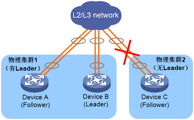
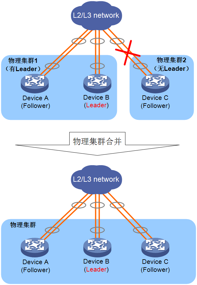
As shown in Figure 15, Device A, Device B, and Device C form a physical cluster, with Device B as the Leader. When the cluster link between Device B and Device C fails, the cluster will split into two clusters, with Device B remaining as the Leader. When the cluster link between Device B and Device C is repaired, Device C can receive Hello messages from the Leader and will join physical cluster 1 as a Follower. Device B continues to act as the Leader of the entire physical cluster.
Figure 15 Merging of a cluster that has a leader and a cluster that does not have a leader
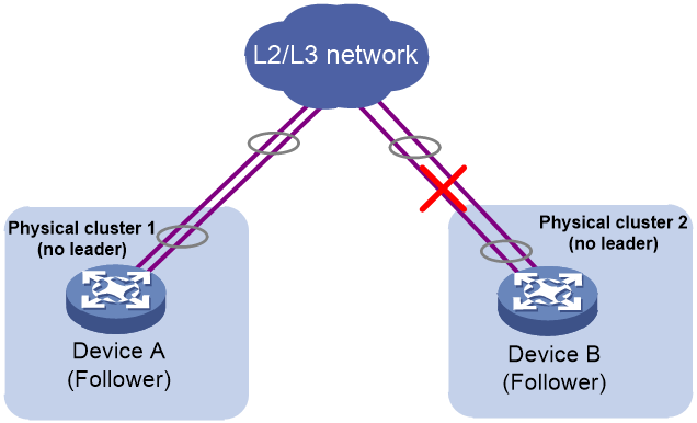
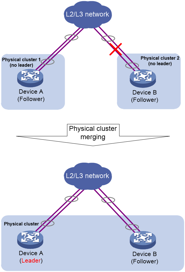
· If both clusters do not have a leader, through the Raft algorithm, a new leader will be elected among the followers. As shown in Figure 16, suppose Device A and Device B originally formed a physical cluster, with Device B as the leader. When the cluster link between Device A and Device B fails, the cluster splits into two clusters. However, because the number of member devices in both clusters is not greater than 2/2, no leader can be elected in either cluster. When the cluster link between Device A and Device B is restored, Device A and Device B can receive voting request messages from each other. Whoever receives the voting response first becomes the leader, and the other acts as a follower. In the figure, suppose Device A receives the voting response first and is elected as the leader.
Figure 16 Merging of two clusters that contain no leader
Container cluster working mechanism
Basic concepts of a container cluster
Operation mode
Comware 9 containers use the cluster mode in factory default settings and support forming container clusters with other Comware 9 containers. Even a single Comware 9 container running on its own is considered a container cluster, but with only one member.
Member container roles
Each container in a container cluster is called a member container. Member containers are divided into the following roles according to their different functions:
· Master container: Responsible for managing and controlling the entire container cluster.
· Standby container: Runs as a backup container for the master container while processing business and forwarding packets. When the master container fails, the system automatically elects a new master container from the standby containers.
When the physical cluster is working normally, the roles of master and standby containers are determined by the leader of the physical cluster. When the physical cluster fails, both the master and standby devices are elected.
Only one master container exists in a container cluster at a time, and all the other member containers are standby containers. For more information about the process of electing container roles, see "Master container election."
Container ID
A container cluster may contain multiple containers, which are uniquely identified by container IDs. The member container IDs are uniformly assigned by the leader of the physical cluster.
In a cloud cluster, the member ID is used to uniquely identify a physical device. Member containers run on physical devices, so member containers use the member ID of the physical device to uniquely identify a container.
In a cloud cluster, only one device can use the default member ID, and you must modify the member IDs for the other devices before adding them to the cloud cluster. When modifying a member ID, make sure that the ID is unique in the cloud cluster.
· When setting up the physical cluster, if there are devices with the same member ID, the later joined device cannot join the physical cluster.
· During the operation of the physical cluster, if a new device joins the physical cluster, but its ID conflicts with the ID of an existing member device, the device cannot join the physical cluster.
Container cluster domain
A domain is a logical concept, and a container cluster corresponds to a container cluster domain.
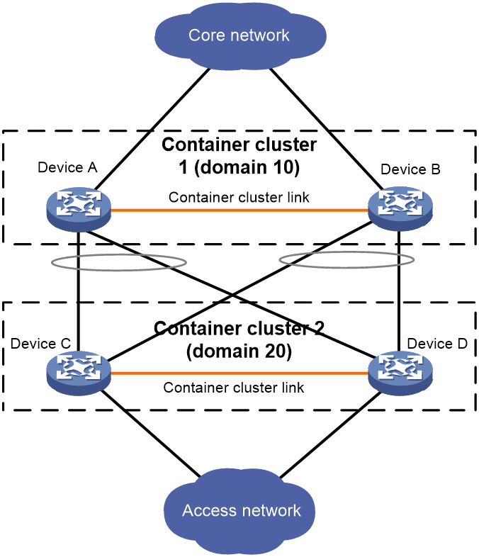
To accommodate various network applications, multiple container clusters can be deployed in the same network, and the container clusters are distinguished by domain IDs. As shown in Figure 17, Device A and Device B form container cluster 1, and Device C and Device D form container cluster 2. By dividing different container clusters with domain IDs, the running and business operations of two container clusters can be kept separate and unaffected by each other.
Figure 17 Multi-container clusters
Container cluster splitting
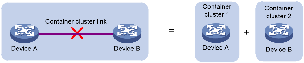
As shown in Figure 18, when a container cluster is formed, if a link fails within the container cluster, causing two adjacent devices to be disconnected, the container cluster splits into two container clusters. This process is called container cluster splitting.
Figure 18 Container cluster splitting
Container cluster merging
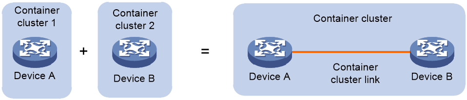
As shown in Figure 19, when two (or more) container clusters are independently running and stable, they can be merged into one container cluster through physical connections and necessary configurations. This process is called container cluster merging.
Figure 19 Container cluster merging
Connectivity topology of a container cluster
Currently, the physical cluster shares the control channel in the container cluster link to transmit physical cluster control messages. To build a container cluster network, the network administrator must use commands to bind the physical interfaces with the control channel and data channel of the container cluster link on the devices. The control channel is used to transmit physical cluster control messages and container cluster control messages between cloud clusters, and the data channel is used to transmit cross-container forwarding data messages.
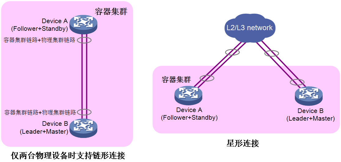
As shown in Figure 20, the physical cluster has the following types of connection topologies: chain-shaped connection and star-shaped connection.
· To use two devices to form a physical cluster, use the chain-shaped or star-shaped connection.
¡ Chain connections are suitable for networks where member devices are physically concentrated.
¡ Star topology connections have lower physical location requirements for member devices than chain connections and are mainly used for networks where member devices are physically dispersed. However, an intermediary device is required to interconnect the member devices.
· To use more than two devices to form a physical cluster, use the star-shaped connection.
Figure 20 Physical connection topology
Container cluster establishment
The Worker component of the cloud platform is responsible for creating and deleting containers.
A Comware 9 container is the basic container of the device, used to implement routing and forwarding functions. Therefore, the device supports Comware 9 container by default. Currently, the physical cluster supports integration only with Comware 9 container and manages Comware 9 containers (such as determining the primary and backup containers). The physical clusters can host other containers based on the Docker technology, but cannot manage the container clusters.
The process of establishing a container cluster is as follows:
1. After a device is powered on and started, it automatically attempts to start the Comware 9 container. The cloud platform Agent inside the container notifies the Worker component of the cloud platform about the container creation and deletion events.
2. The Worker component forwards the container creation and deletion events to the leader in the physical cluster.
3. The leader, based on the physical resource situation of the nodes, determines whether to allow the creation or deletion of the container. If allowed, it then determines the roles of the containers. The first container created is the master container, and any containers created later are standby containers.
4. The leader notifies the Worker to create or delete the container.
5. After the Worker successfully creates or deletes the container, it notifies the leader of the creation or deletion results.
6. The leader updates the container information table (including LIP and container MAC) and the container topology (including Container ID, Member ID, and container MAC) that it maintains. Then, it synchronizes the updated container information table and container topology to all containers in the cloud cluster.
Container monitoring and intelligent management
The cloud platform leader monitors the container service metrics and intelligently manages the containers based on their values.
Container key metrics
Key metrics for containers refer to metrics that represent the fundamental functions of individual containers or container cluster systems, such as chip failures, abnormal CPU port detection, and abnormal board status. Since key metrics have a significant impact on equipment, when a container detects an anomaly in a key metric, it will immediately report the critical event to the Leader. The cloud platform or the inner layer of the container will isolate the faulty node to prevent the fault from escalating. Isolation is divided into the following types:
· Fault isolation: When a container experiences a failure, the cloud platform actively triggers isolation, which is referred to as fault isolation.
When a container is in a fault isolation state, the container's service ports will be shut down. The container cannot forward service packets, nor can it send or receive container cluster control packets. When the fault is rectified, the container will automatically restart to lift the isolation state. After the container's isolation state is lifted, it will rejoin the normally operating container cluster.
· Cluster split isolation: When the physical link between containers is disconnected, the cloud platform or the inner layer of the containers will also trigger isolation, referred to as cluster split isolation.
During cluster split isolation, the service ports of the containers will be shut down. Containers cannot forward service packets, but they can send and receive container cluster control packets. When the faulty link is restored and the container clusters merge, the isolated container cluster will automatically restart and join the normally operating container cluster.
Table 1 Container key metrics
|
No. |
Key metric |
Description |
Values |
Method for the Leader to obtain the metric |
Impact of key metric failures on cloud clusters |
Leader's approach to handling key metric failures |
|
1 |
Chip jam |
Chip blockage periodic detection |
· Normal · Abnormal |
Proactive report |
Container fault |
Fault isolation |
|
2 |
CPU port |
CPU chip pin detection |
· Normal · Abnormal |
Proactive report |
Container fault |
Fault isolation |
|
3 |
Board status |
Module status detection |
· Normal · Abnormal |
Proactive report |
Container fault |
Fault isolation |
|
4 |
Fan status |
Fan status detection |
· Normal · Abnormal |
Proactive report |
Container fault |
Fault isolation |
|
5 |
Temperature status |
Temperature sensor status detection |
· Normal · Abnormal |
Proactive report |
Container fault |
Fault isolation |
|
6 |
Abnormal reboot |
Device abnormal restarts (> 2 times) |
· Normal · Abnormal |
Proactive report |
Container fault |
Fault isolation |
Container service metrics
Container service metrics refer to the service-related metrics within a container that must be closely monitored, such as container health, the number of ARP entries, and the number of MAC entries. Container service metrics are an important basis for the election of master and backup roles within a container. If container service metrics are abnormal, it can affect the container's basic forwarding functions.
In a physical cluster, the Worker component of the cloud platform periodically retrieves the values of container service metrics. If the value of the same service metric differs from the previous value, the Worker will report information such as the container ID, the name of the service metric, and the value of the service metric to the Leader of the physical cluster. The Leader will then take appropriate actions.
Container health reflects the actual health status of the device. Containers with higher health values have a higher priority to be elected as the master container. When several containers have the same health value, the container's service volume represents its operating status. Containers with a higher cumulative service volume have a higher priority to be elected as the master container.
Table 2 Container service metrics
|
No. |
Service metric |
Description |
Values (Integer) |
Metric obtaining method |
Metric reference value |
|
0 |
Device health |
Container health status |
0 to 100 |
Periodic obtaining |
Container health status |
|
1 |
Arp Resource |
Number of ARP entries |
≥ 0 |
Periodic obtaining |
Container service volume |
|
2 |
Mac Resource |
Number of MAC entries |
≥ 0 |
Periodic obtaining |
|
|
3 |
FIB Resource |
Number of FIB forwarding entries |
≥ 0 |
Periodic obtaining |
|
|
4 |
ND Resource |
Number of ND forwarding entries |
≥ 0 |
Periodic obtaining |
|
|
5 |
IPv4 Resource_L2 |
Number of IPv4 Layer 2 multicast entries |
≥ 0 |
Periodic obtaining |
|
|
6 |
IPv6 Resource_L2 |
Number of IPv6 Layer 2 multicast entries |
≥ 0 |
Periodic obtaining |
|
|
7 |
IPv4 Resource_L3 |
Number of IPv4 Layer 3 multicast entries |
≥ 0 |
Periodic obtaining |
|
|
8 |
IPv6 Resource_L3 |
Number of IPv6 Layer 3 multicast entries |
≥ 0 |
Periodic obtaining |
|
|
9 |
ACL Resource |
ACL resources |
≥ 0 |
Periodic obtaining |
Master container election
Master container election takes place in the following situations:
· The container cluster is established.
· The master container leaves or fails.
· The container cluster splits.
· Two (or more) independently running container clusters merge into one container cluster.
Election at container cluster establishment
When a container cluster is established for the first time or the entire container cluster restarts, the container that is started first becomes the master container. The other containers become the standby containers. Therefore, after the entire container cluster restarts, it is possible for another container to be elected as the master container.
Election upon master container leaving or failure or cluster split
When the master container leaves or fails, or when the container cluster splits, the master container role election process is triggered as follows:
1. The current master container is given priority, meaning that the container cluster will not elect a new master container even if a new member container with a higher priority joins. This rule does not apply when the container cluster is formed, as all joined devices consider themselves as the master device.
2. Containers with a higher health value are given priority to be elected as the master container.
3. Containers with a longer running time are given priority. In the container cluster, the measurement precision of running time is 10 minutes. If the startup time interval of devices is less than or equal to 10 minutes, they are considered to have equal running time.
4. Containers with higher cumulative service volumes are given priority.
5. Containers with lower CPU MAC addresses are given priority.
The optimal member container selected based on the above rules becomes the master container. Once the master container is determined, it immediately broadcasts a Hello message to announce its master container identity. Health, and service volume information. Upon receiving this message, other containers stop the role election process and function as standby containers. Standby containers unicast Hello messages to the master container, carrying their own role, health, and service volume information. The master container collects information and topology of all standby containers through Hello messages and reports this information to the leader. Once the container cluster information is updated, Hello messages are periodically sent between the master and standby containers to maintain the container cluster relationship.
Cloud clusters support a dual-layer election mechanism for the master container, which enhances the reliability and robustness of the container cluster:
1. When the physical cluster is running normally, the leader of the physical cluster selects the master container based on the master container role election rules.
2. When the physical cluster is unable to run normally (no leader), the container cluster itself selects the master container based on the master container role election rules.
Election at container cluster merging
See "Container cluster merging."
Container cluster splitting and MAD
About MAD
A link failure in a container cluster can lead to the splitting into multiple new container clusters. These container clusters have the same IP address and other layer 3 configurations, causing address conflicts and amplifying the network failure. To improve system availability, a mechanism is required to detect the presence of multiple container clusters in the network and handle them accordingly, minimizing the impact of container cluster splitting on business operations. Multi-Active Detection (MAD) is such a mechanism that provides split detection, conflict resolution, and fault recovery functionalities.
Cloud clusters support the following types of MAD: Cloud platform MAD and LACP MAD within containers. Cloud clusters prefer to use cloud platform MAD, and when cloud platform MAD is not available, LACP MAD is used.
Figure 21 Comparison of different MAD types
|
MAD type |
Advantages |
Limits |
Application scenarios |
|
Cloud platform MAD |
Feature that comes with physical clusters Additional configuration not required |
For products that support shared container cluster and physical cluster links and dedicated physical cluster links, cloud platform MAD can take effect as long as the physical cluster links are up (the physical cluster is not split) |
All cloud cluster networks |
|
LACP MAD |
High detection speed Supplements to cloud platform MAD |
To transmit LACP MAD detection messages, it is necessary to use H3C devices (supporting extended LACP protocol packets) as intermediate devices, and each member container must be connected to the intermediate device. |
Container cluster that use aggregated links to connect with upstream or downstream devices |
Split detection
During the operation of the container cluster, the master container and the standby containers periodically send Hello messages to each other to maintain the cluster relationship. If a standby container does not receive a Hello message from the master container within the specified timeout period, it is considered that the master container failed.
The containers send Hello messages to detect the number of connected member containers based on their local records of container cluster member information and topology. This detected information is then reported to the leader.
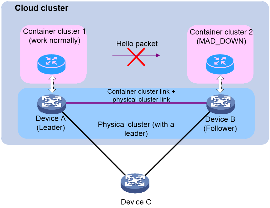
· If a leader exists in the current physical cluster, it triggers cloud platform MAD. If cloud platform MAD determines that the container cluster has split, it resolves the existing conflicts.
As shown in Figure 22, the physical devices Device A and Device B form a physical cluster, and Comware containers are running on each device, forming a container cluster. When a link failure occurs, causing the failure on the standby container to receive a Hello message from the master container, the container cluster split into container cluster 1 and container cluster 2. However, because the physical cluster links are usually intact, the physical cluster continues to function normally. At this time, cloud platform MAD is used to handle the split of the container cluster.
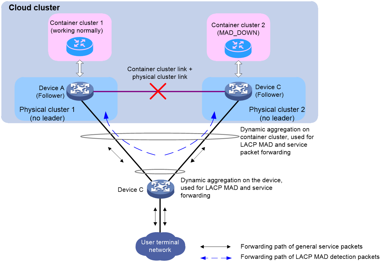
· If no leader exists in the current physical cluster, the container cluster that does not include the master container elects a new master container based on the election rules. LACP MAD discovers that two master containers exist in the same container cluster domain through LACP, and considers that the container cluster has split. For more information about LACP, see configuring Ethernet link aggregation in Network Connectivity Configuration Guide.
As shown in Figure 23, the physical devices Device A and Device B form a physical cluster, and Comware containers are running on each device, forming a container cluster. When a link failure occurs within the container cluster, the container cluster splits into container cluster 1 and container cluster 2. Since the physical cluster links are shared with the container cluster links, the physical cluster also splits. In the absence of a leader in the physical cluster to handle the MAD event, LACP MAD handles the split of the container cluster.
Conflict handling
The conflict handling mechanisms of cloud platform MAD and LACP MAD are slightly different.
· Conflict handling mechanism of cloud platform MAD:
When cloud platform MAD detects a split in the container cluster, it performs the following conflict handling steps:
a. The container cluster with more members is given priority.
The container cluster with more member containers continues to work. The container cluster with fewer member containers is migrated to Recovery state (disabled state).
Meanwhile, the master container of the container cluster before the split continues to run as the master container, and a new master container is elected for the other container cluster according to the election rules. In this way, both container clusters have their respective master containers.
b. The container cluster with higher health status is given priority.
The health status of the primary devices in both container clusters is compared. The container cluster with higher health status continues to work. The other container cluster is migrated to Recovery state (disabled state).
c. The container with a longer running time as the master is given priority.
d. The container with a lower CPU MAC address as the master is given priority.
After the container cluster is migrated to Recovery state, all service ports on the member containers in that cluster, except for the reserved ports, are closed to ensure that the cluster cannot forward service packets. You can use the mad exclude interface command to configure the reserved ports.
· Conflict handling mechanism of LACP MAD:
When LACP MAD detects a split in the container cluster, it performs the following conflict handling mechanisms:
a. The health status of the master containers in both clusters is compared, and the container cluster with higher health status continues to work while the other container cluster is migrated to Recovery state (disabled state).
b. If the health status is equal, the number of member containers in both container clusters is compared. The container cluster with more member containers continues to work while the other container cluster is migrated to Recovery state (disabled state).
c. If the number of member containers is also equal, the container cluster with smaller master member ID continues to work while the other container cluster is migrated to Recovery state.
After the container cluster is migrated to Recovery state, all service ports on the containers in that cluster, except for the reserved ports, are closed to ensure that the cluster cannot forward service packets. You can use the mad exclude interface command to configure the reserved ports.
MAD fault recovery
The MAD fault recovery methods are the same for cloud platform MAD and LACP MAD:
1. Repair the faulty link to automatically merge the split container clusters.
2. If the link is still not repaired but the normally working container cluster also fails, the container cluster in Recovery state can be enabled as an emergency backup.
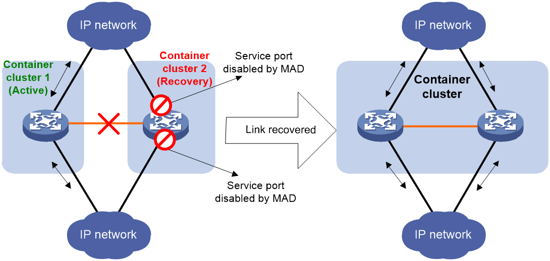
A container cluster link failure causes the container cluster to split, resulting in multiple Active conflicts. Therefore, repairing the faulty container cluster link and merging the conflicting container clusters back into one can restore the container cluster fault.
After the container cluster link is repaired, the system automatically restarts the container cluster in Recovery state. After the restart, all member containers in the Recovery container cluster join the normal working container cluster as container members. The service interfaces that were forcibly closed in the Recovery container cluster will automatically recover to their actual physical state. The entire container cluster system is then restored, as shown in Figure 24.
|
|
CAUTION: Restart the container cluster in Recovery state according to the instructions. If you mistakenly restart the container cluster in the normal working state, the merged container cluster will still be in Recovery state and all member devices' service interfaces will be closed. In such a situation, execute the mad restore command to restore the entire container cluster system. |
Figure 24 MAD fault recovery (link failure in container cluster)
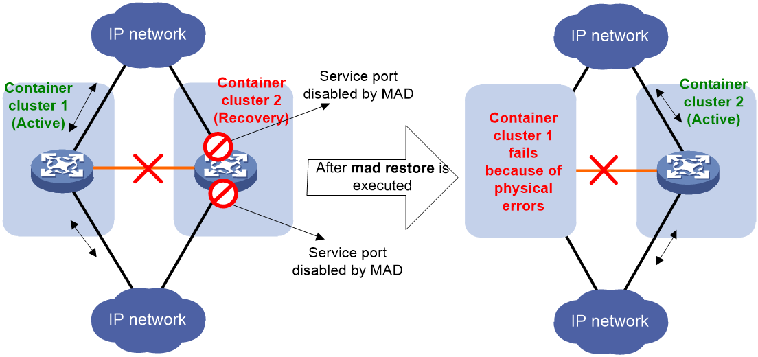
If the container cluster in working state fails due to reasons such as device failure or uplink/downlink line failure, you can execute the mad restore command on the cluster in Recovery state. This operation restores the Recovery cluster to a normal state and replaces the failed working container cluster. Then, fix the faulty container cluster and links.
Figure 25 MAD fault recovery (normally working cluster failure before fault recovery)
Container cluster merging
The merging of container clusters is divided into the following two cases depending on whether the MAD function is enabled:
· If the physical cluster can work normally or LACP MAD is configured, when a container cluster link fails and causes the container cluster to split, the cloud cluster lets one container cluster to work normally. The other container cluster will be disabled (in Recovery state). If the faulty link between the two split container clusters is restored, the two container clusters will automatically merge. The container cluster in Recovery state will automatically restart and join the current normally running container cluster as standby containers.
· If the physical cluster cannot work normally and LACP MAD is not configured, when the container cluster link fails and causes the container cluster to split, both container clusters will work normally (dual master phenomenon). In this case, if the faulty link between the two container clusters is restored, the two container clusters will automatically merge and master container election will be carried out. The election rules are as follows:
a. The master container with more member containers wins.
b. The master container running for a longer time wins.
c. The master container with higher health value wins.
d. The master container with a higher cumulative service volume wins.
e. The master container with a smaller CPU MAC address wins.
The container cluster that wins the master container election continues to work, while the cluster that fails automatically restart and join the working container cluster as standby containers.
Cloud cluster configuration method
A Comware container runs on a physical device and the physical cluster shares the control links of the container cluster. When you make a network plan, perform the following tasks:
1. Identify the number of member devices in the cloud cluster. In the current software version, a cloud cluster supports up to two member devices.
2. Identify hardware compatibility and restrictions of physical devices.
3. Determine the roles of devices in the physical cluster. Devices participating in the management of the physical cluster must be configured as manager-worker, while devices not involved in the management of the physical cluster must be configured as worker.
4. Complete the configuration of the cloud cluster, including configuring member IDs, member IPs, member roles, IPs of members to be added to the cluster, and binding cluster ports.
5. Connect the physical cables of the cluster.
6. Activate the cluster configuration for the devices to form a cluster.
Configuring a cloud cluster
system-view
2. Set the container cluster domain ID.
cloud-cluster service-cluster domain domain-id
By default, the container cluster domain ID is 0.
|
|
CAUTION: Changing the container cluster domain number of a container will cause the container to leave the current container cluster. The container no longer belongs to the current container cluster and will not be able to exchange container cluster control messages with other devices in the current container cluster. |
3. Enter cloud cluster member view.
cloud-cluster member member-id
By default, the member ID is 1.
4. Configure the member IP address for the device.
member-ip ipv4-addr mask-length
By default, the member IP address is not configured.
5. Specify the cluster IP address on the follower device of Manager.
join-cluster ip ipv4-address
By default, the cluster IP address is not specified.
To configure a physical cluster, you must configure this command on the follower device of Manager. This command is not required on the leader device and the Manager that is not configured with this command will join the self-created cluster automatically as a leader device.
6. Bind cluster links with physical interfaces.
cluster-link [ control | data ] bind interface interface-type interface-number
By default, cluster links are not bound to any physical interface.
7. Return to system view.
quit
8. Edit the member ID of the device.
cloud-cluster member member-id renumber new-member-id
By default, the member device ID is 1.
Only one device in the cloud cluster can use the default member ID and other devices must first edit their member IDs to join the cloud cluster. When you edit the member ID, make sure the ID is unique in the cluster.
9. Activate the physical cluster configuration.
cloud-cluster configuration active
Executing this command will reboot the device. During the reboot process, the device will provide interactive information. Select to save the configuration and reboot the device. The new member number will take effect only after the device restarts.
Moving a device from physical cluster A to physical cluster B
About this task
To move a device from physical cluster A to physical cluster B, first remove the device from cluster A. During the removal, the configuration, data, and typology of cluster A will be deleted from the device and container-related configuration will be retained. Then, the device acts as the leader to build a cluster and the container on the device operates as master. Through further configuration, you can add the device to cluster B. The device cannot be added to cluster B if data of cluster A remains on the device.
Removing the device from physical cluster A
1. Disconnect cluster links and remove the device from physical cluster A.
2. Log in to the device.
3. Enter system view.
system-view
4. Enter cloud cluster member view.
cloud-cluster member member-id
By default, the device member ID is 1.
5. Remove the device from the cluster.
undo join-cluster
6. Return to system view.
quit
7. Active the physical cluster configuration.
cloud-cluster configuration active
Refer to the prompt information on the device to see whether the device reboots automatically after this command is executed.
Adding the device to physical cluster B
1. Enter system view.
system-view
2. Enter cloud cluster member view.
cloud-cluster member member-id
By default, the device member ID is 1.
3. Configure the member IP address for the device. Make sure the IP address and other member IP addresses in cluster B are in the same subnet.
member-ip ipv4-addr mask-length
4. Specify the IP address of the leader device in cluster B as the cluster IP address.
join-cluster ip ipv4-address
5. Return to system view.
quit
6. (Optional.) Edit the device member ID. If the current member ID of the device is not used in cluster B, skip this step.
cloud-cluster member member-id renumber new-member-id
7. Connect cluster links and add the device to cluster B.
8. Activate the physical cluster configuration.
cloud-cluster configuration active
Refer to the prompt information on the device to see whether the device reboots automatically after this command is executed.
Display and maintenance commands for physical clusters
· To view information about the physical cluster, use the following command in any view:
display cloud-cluster [ member member-id ] [ verbose ]
· To view cloud cluster configuration information, use the following command in any view:
display cloud-cluster configuration [ member member-id ]
Configuring container cluster MAD
Configuring LACP MAD
About this task
The MAD domain ID of the container cluster is used only for MAD. All member devices in the cloud cluster share this MAD domain ID. Upon receiving a MAD packet, a container compares the MAD domain ID in the packet with the local MAD domain ID. The container processes the MAD packet only if the two MAD domain IDs are the same. Containers in the same cloud cluster must use the same MAD domain ID. To ensure the correct running of MAD, make sure each cloud cluster uses a unique MAD domain ID.
You can change the MAD domain ID of container clusters by using the cloud-cluster service-cluster mad domain or mad enable command. The MAD domain IDs configured by using these commands overwrite each other. As a best practice, set the MAD domain ID for container clusters according to the network plan, and do not change the MAD domain ID unless necessary.
Restrictions and guidelines
Assigning MAD domain IDs to container clusters
If LACP MAD runs between two container clusters, assign each container cluster a unique MAD domain ID.
Actions on interfaces shut down by MAD
To prevent a multi-active collision from causing network issues, avoid using the undo shutdown command to bring up the interfaces shut down by a MAD mechanism on a Recovery-state container cluster.
Procedure
1. Enter system view.
system-view
2. Assign a MAD domain ID to the container cluster.
cloud-cluster service-cluster mad domain domain-id
The default MAD domain ID is 0.
|
|
CAUTION: Changing the container cluster domain number of a container will cause the container to leave the current container cluster. The container no longer belongs to the current container cluster and will not be able to exchange container cluster control messages with other devices in the current container cluster. |
3. Create a Layer 2 or Layer 3 aggregate interface and enter its view.
¡ Create a Layer 2 aggregate interface.
interface bridge-aggregation interface-number
¡ Create a Layer 3 aggregate interface.
interface route-aggregation interface-number
You must also perform this task on intermediate devices.
4. Configure the aggregation group to operate in dynamic aggregation mode.
link-aggregation mode dynamic
By default, an aggregation group operates in static aggregation mode.
Perform this step also on the intermediate device.
5. Enable LACP MAD.
mad enable
By default, LACP MAD is disabled.
6. Return to system view.
quit
7. Enter Ethernet interface view.
interface interface-type interface-number
8. Assign the Ethernet port to the specified aggregation group.
port link-aggregation group group-id
Perform this step also on the intermediate device.
Excluding interfaces from the shutdown action upon detection of multi-active collision
About this task
When a container cluster transits to the Recovery state, the system automatically excludes the following network interfaces from being shut down:
· Container cluster physical interfaces.
· Member interfaces of an aggregate interface if the aggregate interface is excluded from being shut down.
You can exclude an interface from the shutdown action for management or other special purposes. For example:
· Exclude a port from the shutdown action so you can Telnet to the port for managing the device.
· Exclude a VLAN interface and its Layer 2 ports from the shutdown action so you can log in through the VLAN interface.
Restrictions and guidelines
If the Layer 2 ports of a VLAN interface are distributed on multiple member devices, the exclusion operation might introduce IP collision risks. The VLAN interface might be up on both active and inactive container clusters.
Procedure
1. Enter system view.
system-view
2. Configure an interface to not shut down when a container transits to the Recovery state.
mad exclude interface interface-type interface-number
By default, all network interfaces on a Recovery-state container are shut down, except for the network interfaces automatically excluded by the system.
Recovering a container cluster
About this task
If the active container cluster fails before the link is recovered, perform this task on the inactive container cluster to recover the inactive container cluster for traffic forwarding. The manual recovery operation brings up all interfaces that were shut down by MAD on the inactive container cluster.
Procedure
1. Enter system view.
system-view
2. Recover the inactive container cluster.
mad restore
Optimizing container cluster settings
Enabling software auto-update for software image synchronization
About this task
The software auto-update feature automatically propagates the current software images of the master in the cloud cluster to member devices you are adding to the cloud cluster. Those devices will join the cloud cluster again after software image synchronization.
When the software auto-update feature is disabled, new devices can join the cloud cluster even if their software images are different from those of the master in the cloud cluster. However, the software image differences might affect the running of some cloud cluster features on the new member devices. As a best practice to avoid such issue, enable the software auto-update feature.
Prerequisites
To ensure a successful software update, verify that the new device you are adding to the cloud cluster has sufficient storage space for the new software images. If the device does not have sufficient storage space, the cloud cluster automatically deletes the current software images of the device. If the reclaimed space is still insufficient, the device cannot complete the auto-update. You must reboot the device, and then access the BootWare menus to delete unused files.
Procedure
1. Enter system view.
system-view
2. Enable software auto-update.
cloud-cluster auto-update enable
By default, software auto-update is enabled.
Configuring container cluster bridge MAC persistence
About this task
The bridge MAC address of a system must be unique on a switched LAN. Container cluster MAC address identifies a container cluster by Layer 2 protocols (for example, LACP) on a switched LAN.
A container cluster usually uses the bridge MAC address of the primary container as its bridge MAC address. In this situation, the primary container is called the address owner of the container cluster bridge MAC address. After the primary container leaves, the container cluster bridge MAC address persists for a period of time or permanently depending on the container cluster bridge MAC persistence setting.
When container clusters merge, bridge MAC addresses are processed as follows:
1. Container cluster merge fails if any two member containers have the same bridge MAC address. Container cluster bridge MAC addresses do not affect container cluster merge.
2. After container clusters merge, the new container cluster uses the bridge MAC address of the container cluster that won the election as the container cluster bridge MAC address.
Restrictions and guidelines
|
|
CAUTION: Bridge MAC address conflicts cause communication failures. Bridge MAC address changes cause transient traffic disruption. |
If a container cluster has cross-member aggregate links, do not use the undo cloud-cluster service-cluster mac-address persistent command. Using this command might cause traffic disruption.
Procedure
1. Enter system view.
system-view
2. Configure container cluster bridge MAC persistence. Perform one of the following tasks:
¡ Retain the container cluster bridge MAC address permanently even if the address owner has left the container cluster.
cloud-cluster service-cluster mac-address persistent always
¡ Retain the container cluster bridge MAC address for 6 minutes after the address owner leaves the container cluster.
cloud-cluster service-cluster mac-address persistent timer
This command avoids unnecessary bridge MAC address changes caused by device reboot, transient link failure, or purposeful link disconnection.
¡ Change the container cluster bridge MAC address as soon as the address owner leaves the container cluster.
undo cloud-cluster service-cluster mac-address persistent
By default, the container cluster bridge MAC address does not change after the address owner leaves.
Setting the retention time of the container cluster bridge MAC to a fixed value of 6 minutes is suitable for situations where the bridge MAC owner leaves and returns to the container cluster within a short time (such as device reboot or temporary link failure). This can reduce unnecessary bridge MAC switches that lead to traffic interruption.
Delaying reporting container cluster link down events
About this task
Application scenarios
To prevent frequent container cluster splits and merges during link flapping, configure the container cluster interfaces to delay reporting link down events.
Operating mechanism
Container cluster links have two physical states, up and down. Container cluster interfaces do not delay reporting link up events. They report link up events immediately after the container cluster links come up.
After you set a delay time for container cluster link down report, a container cluster interface does not report a link down event to the container cluster immediately after its link goes down. If the container cluster link is still down when the delay time is reached, the interface reports the link down event to the container cluster.
Restrictions and guidelines
If some features (for example, CFD and OSPF) are used in the container cluster, set the delay interval shorter than the timeout timers of those features to avoid unnecessary state changes.
· Services require high-speed primary/secondary switchover and container cluster links.
· Before shutting down physical ports of the container cluster or rebooting member containers, set the container cluster link down report delay to 0. After you finish the operation, restore the former link down report delay value.
Procedure
1. Enter system view.
system-view
2. Set a delay for the container cluster interfaces to report link down events.
cloud-cluster link-delay interval
By default, the delay interval is 0. The container cluster interfaces report link down events without delay.
Enabling cloud cluster auto-merge
About this task
Application scenarios
The auto-merge feature takes effect on merges caused by the following events:
· The cloud cluster link recovers from a link failure.
· The cloud clusters to be merged already have the cloud cluster port bindings required for merging, and those port bindings are activated.
Operating mechanism
Cloud clusters that are merging perform master election. The auto-merge feature enables member devices in the cloud cluster that fails the master election to automatically reboot for completing the cloud cluster merge. If the cloud cluster auto-merge feature is disabled, you must log in to the cloud cluster that fails master election, and then follow the system instructions to manually reboot member devices in the cloud cluster. Only in this way can the member devices in the failing cloud cluster join the winning cloud cluster.
For a successful merge, make sure the cloud cluster auto-merge feature is enabled on both cloud clusters that are merging.
Procedure
1. Enter system view.
system-view
2. Enable cloud cluster auto-merge.
cloud-cluster auto-merge enable
By default, the cloud cluster auto-merge feature is enabled. The cloud cluster that has failed in the master election reboots automatically to complete the cloud cluster merge.
Isolating the master in the container cluster
About this task
With the growing popularity of cloud computing and container technology, proactive container isolation is required to improve cluster stability and availability. When the master container in a cluster requires an upgrade or hardware replacement, or encounters a failure, you can perform this task to proactively isolate the master. This allows the cluster to promptly elect a new master container to take over tasks.
The system performs proactive container isolation as follows:
1. Automatically sets the management Ethernet interface of the master container as a MAD reserved port temporarily.
2. Notifies the container cluster to elect a new master container.
3. Disables all interfaces on the device, except the MAD reserved ports. The state of the disabled port changes to MAD down. MAD reserved ports include the management Ethernet interface and those configured by the mad exclude interface command.
4. Sets the state of the master container to be isolated to Recovery.
The Status field displays MAD down for an isolated container in the output of the display cloud-cluster service-cluster container command.
Restrictions and guidelines
· Note that executing this command will cause the container cluster to split and isolate the master container from the cluster.
· When the cloud cluster has only one device, do not execute this command, because this command will prevent the cluster from operating.
Isolating the master in the container cluster
1. Enter system view.
system-view
2. Enter management Ethernet interface view.
interface m-gigabitethernet interface-number
1. Configure an IP address for the management Ethernet interface for each container in the container cluster.
ip address ip-address { mask-length | mask } cluster-member member-id
By default, no interface IP address is configured.
This command takes effect only on the management Ethernet interface of the master container. You can use the IP address configured for the management Ethernet interface of the master container to log in to the container cluster for configuration and maintenance purposes.
2. Return to system view.
quit
3. (Optional) Configure an interface to not shut down when a container transits to the Recovery state.
mad exclude interface interface-type interface-number
By default, all network interfaces on a Recovery-state container are shut down, except for the network interfaces automatically excluded by the system
4. Isolate the master container in the container master.
cloud-cluster service-cluster isolate master
Restoring the isolated master container to normal
To restore the isolated master container to its normal working state, manually executing the reboot command. After the reboot, the container will join other containers as a standby container.
Configuring cloud cluster optimization for WLAN access
About this task
Use this feature to guarantee reliable AP and client access. This feature accelerates cloud cluster master election, new member joining, and cloud cluster member role change to prevent cloud cluster events from causing unstable AP and client access.
Procedure
1. Enter system view.
system-view
2. Enable cloud cluster optimization for WLAN access.
cloudcluster-optimize wlan reliable-access
By default, WLAN access optimization is enabled in a cloud cluster fabric.
Verifying and maintaining container clusters
display cloud-cluster service-cluster container [ container-id ] [ verbose ]
To display the status of the flag bits during the master/standby switchover process in the cloud cluster, execute the following command in any view:
display wlan ap statistics cloud-cluster switch-over-state
Accessing the container cluster
Comware 9-based container provides human-machine interaction interfaces for login, such as command lines, SNMP, NETCONF, CWMP, and Web interface. After you log in to the Comware 9-based container cluster, you can perform the following tasks:
· Access the container cluster and the physical cluster.
· View all configurations of the cloud cluster and information about the cloud cluster (including the container cluster and the physical cluster).
Use either of the following methods to log in to the command line interface (CLI) of the container cluster:
· Local login—Log in through the AUX or console port of any member container.
· Remote login—Log in at a Layer 3 interface on any member container by using methods including Telnet, Web, and SNMP.
After you log in to the container cluster, you are placed at the CLI of the primary container. The primary container synchronizes all user settings to the secondary containers.
The primary container synchronizes physical cluster settings made by the network administrator to the cluster leader through the cloud platform Agent component. The cluster leader then synchronizes the settings to all the managers and workers. In this way, you can realize the management of the entire cloud cluster.
Cloud cluster configuration examples
Example: Configuring a cloud cluster
Network configuration
As shown in Figure 26, perform the following tasks:
· Set up a cloud cluster that contains AC 1 and AC 2.
· Configure dynamic aggregate links between the cloud cluster and switches Core 1 and Core 2, which are used for LACP multi-active detection (MAD) and service packet forwarding.
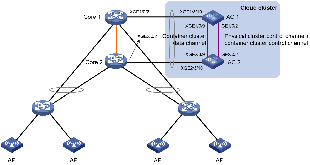
Procedure
1. Configure Core 1 and Core 2:
Before you configure Core 1 and Core 2, make sure they form a stable Comware 7-based IRF fabric.
# Create Layer 2 aggregate interface Bridge-Aggregation 1, and set the link aggregation mode to dynamic.
<Core> system-view
[Core] interface bridge-aggregation 1
[Core-Bridge-Aggregation1] link-aggregation mode dynamic
[Core-Bridge-Aggregation1] quit
# Assign Ten-GigabitEthernet 1/0/2 to aggregation group 1.
[Core] interface ten-gigabitethernet 1/0/2
[Core-Ten-GigabitEthernet1/0/2] port link-aggregation group 1
[Core-Ten-GigabitEthernet1/0/2] quit
# Assign Ten-GigabitEthernet 2/0/2 to aggregation group 1.
[Core] interface ten-gigabitethernet 2/0/2
[Core-Ten-GigabitEthernet2/0/2] port link-aggregation group 1
[Core-Ten-GigabitEthernet2/0/2] quit
# AC1 in the cloud cluster uses the default member ID, which is 1. You do not need to edit it.
# Specify the member IP address for AC1.
Make sure the member IP addresses of the member devices in the cloud cluster reside on the same network segment. Plan the network segment in advance. This document uses 192.168.10.x/24 as an example.
<AC1> system-view
[AC1] cloud-cluster member 1
[AC1-ccluster-member-1] member-ip 192.168.10.10 24
# Add 192.168.10.10 to the cloud cluster. (If the device is the cluster leader, skip this procedure.)
[AC1-ccluster-member-1] join-cluster ip 192.168.10.10
# Bind GigabitEthernet 1/0/2 to the control channel and Ten-GigabitEthernet 1/3/9 to the data channel.
[AC1-ccluster-member-1] cluster-link control bind interface gigabitethernet 1/0/2
The system will shut down and then bring up the interface after activation the cloud cluster configuration. Continue? [Y/N]: y
[AC1-ccluster-member-1] cluster-link data bind interface ten-gigabitethernet 1/3/9
The system will shut down and then bring up the interface after activation the cloud cluster configuration. Continue? [Y/N]: y
[AC1-ccluster-member-1] quit
# Activate the cloud cluster configuration.
[AC1] cloud-cluster configuration active
New cluster configuration:
cloud-cluster service-cluster domain 0
cloud-cluster hello cloud-timeout 7 service-timeout 10
cloud-cluster member 1
member-ip 192.168.10.10/24
join-cluster ip 192.168.10.10
role manager-worker
cluster-link control bind interface GigabitEthernet 1/0/2
cluster-link data bind interface Ten-GigabitEthernet 1/3/9
The system will activate and save the configuration, and it might do a restart. Continue? [Y/N]:y
The current configuration will be written to the device. Are you sure? [Y/N]:y
Please input the file name(*.cfg)[flash:/startup.cfg]
(To leave the existing filename unchanged, press the enter key):test.cfg
Validating file. Please wait...
Saved the current configuration to mainboard device successfully
The cloud cluster configuration takes effect after the reboot.
3. Configure AC 2:
# Specify 192.168.10.11/24 as the member IP address for AC 2. Make sure the member IP addresses of AC1 and AC2 reside on the same network segment.
<AC2> system-view
[AC2] cloud-cluster member 1
[AC2-ccluster-member-1] member-ip 192.168.10.11 24
# Add 192.168.10.10 to the cloud cluster.
[AC2-ccluster-member-1] join-cluster ip 192.168.10.10
# Bind GigabitEthernet 1/0/2 to the control channel and Ten-GigabitEthernet 1/3/9 to the data channel.
[AC2-ccluster-member-1] cluster-link control bind interface GigabitEthernet 1/0/2
The system will shut down and then bring up the interface after activation the cloud cluster configuration. Continue? [Y/N]: y
[AC2-ccluster-member-1] cluster-link data bind interface Ten-GigabitEthernet 1/3/9
The system will shut down and then bring up the interface after activation the cloud cluster configuration. Continue? [Y/N]: y
[AC2-ccluster-member-1] quit
# Change the member ID of AC 2 to 2. (The member ID of each member device in the cloud cluster must be unique.)
[AC2] cloud-cluster member 1 renumber 2
This command will take effect after the cloud cluster configuration is activated. The command might result in configuration change or loss when it takes effect. Continue? [Y/N]: y
# Activate the cloud cluster configuration.
[AC2] cloud-cluster member 1
[AC2-ccluster-member-1]quit
[AC2] cloud-cluster configuration active
New cluster configuration:
cloud-cluster service-cluster domain 0
cloud-cluster hello cloud-timeout 7 service-timeout 10
cloud-cluster member 2
member-ip 192.168.10.11/24
join-cluster ip 192.168.10.10
role manager-worker
cluster-link control bind interface GigabitEthernet 2/0/2
cluster-link data bind interface Ten-GigabitEthernet 2/3/9
The system will activate and save the configuration, and it might do a restart. Continue? [Y/N]:y
The current configuration will be written to the device. Are you sure? [Y/N]:y
Please input the file name(*.cfg)[flash:/startup.cfg]
(To leave the existing filename unchanged, press the enter key):test.cfg
Validating file. Please wait...
Saved the current configuration to mainboard device successfully
The cloud cluster configuration takes effect after the reboot. AC2 is added to the physical cluster as a follower. In the container cluster, the container on AC 1 is the primary and the container on AC 2 is the secondary.
4. Display the cluster status to verify that the cloud cluster has been set up successfully.
# Display information about the physical cluster.
<AC1> display cloud-cluster
Manager list:
Member ID Role Member IP State Heartbeat(ms)
1 Leader 192.168.10.10 online 100
2 Follower 192.168.10.11 online 0
Worker list:
Member ID State Heartbeat(ms) Joined at
1 online 100 2023-02-12 06:13:28
2 online 200 2023-02-12 06:13:28
The output shows that the physical cluster has two member devices. AC 1 is the leader and AC 2 is the follower.
# Display information about the container cluster.
<AC1> display cloud-cluster service-cluster container
Container ID Slot ID Member ID Role Status
*+1 1 1 Master Online
2 2 2 Standby Online
---------------------------------------------------------------
* indicates the device is the master.
+ indicates the device through which the user logs in.
The output shows that the container on AC 1 is the primary and the container on AC 2 is the secondary.
5. Configure LACP MAD:
# Create Layer 2 aggregate interface Bridge-Aggregation 1, and set the link aggregation mode to dynamic.
<AC1> system-view
[AC1] interface bridge-aggregation 1
[AC1-Bridge-Aggregation1] link-aggregation mode dynamic
# Enable LACP MAD.
[AC1-Bridge-Aggregation1] mad enable
You need to assign a domain ID (range: 0-4294967295)
[Current domain ID is: 0]: 1
The assigned domain ID is: 1
[AC1-Bridge-Aggregation1] quit
# Assign Ten-GigabitEthernet 1/3/10 to aggregation group 1.
[AC1] interface ten-gigabitethernet 1/3/10
[AC1-Ten-GigabitEthernet1/3/10] port link-aggregation group 1
[AC1-Ten-GigabitEthernet1/3/10] quit
# Assign Ten-GigabitEthernet 2/3/10 to aggregation group 1.
[AC1] interface ten-gigabitethernet 2/3/10
[AC1-Ten-GigabitEthernet2/3/10] port link-aggregation group 1
[AC1-Ten-GigabitEthernet2/3/10] quit
Example: Replacing a faulty physical device
Network configuration
As shown in Figure 27, AC 1 in the cloud cluster has failed. Replace it with a new device of the same model.
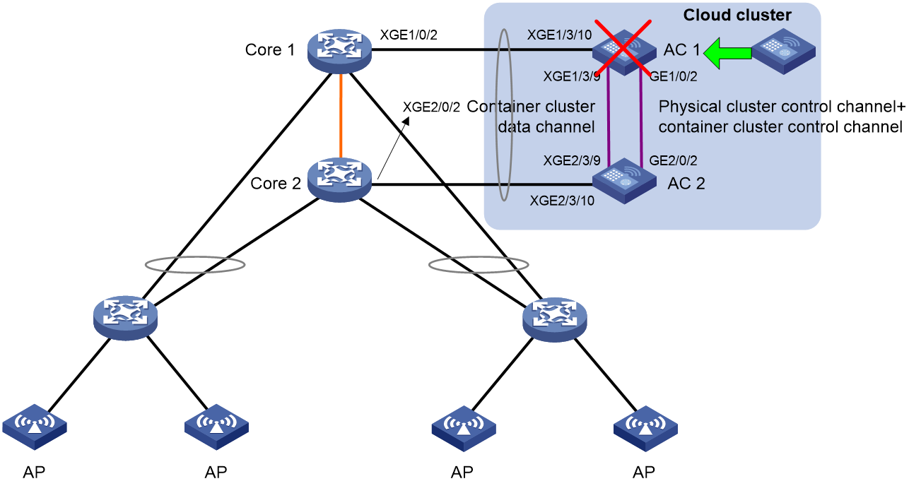
Analysis
1. Isolate AC 2 from the cloud cluster and activate the physical cluster configuration on AC 2. Perform this procedure to delete information about AC 1 from the local topology of AC 2. If you do not perform this procedure, the physical cluster determines that a member ID conflict has occurred when you add the new device with the same member ID as AC 1 to it. As a result, the new device fails to be added to the physical cluster.
2. Log in to the new device. Configure the IP address to be added to the cluster as the member IP address of AC 2.
3. Remove AC 1 from the network.
4. Copy the configuration of AC 1 to the new device or perform the configuration of AC 1 on the new device again.
5. Connect the new device to the network.
Procedure
1. Configure AC 2:
# Isolate AC 2 from the cloud cluster.
<AC2> system-view
[AC2] cloud-cluster member 2
[AC2-ccluster-member-2] undo join-cluster
[AC2-ccluster-member-2] quit
[AC2] cloud-cluster configuration active
New cluster configuration:
cloud-cluster service-cluster domain 0
cloud-cluster hello cloud-timeout 7 service-timeout 10
cloud-cluster member 2
member-ip 192.168.10.11/16
role manager-worker
cluster-link bind interface GigabitEthernet 2/0/1
The system will activate and save the configuration, and it might do a restart. Continue? [Y/N]:Y
The current configuration will be written to the device. Are you sure? [Y/N]:y
Please input the file name(*.cfg)[flash:/startup.cfg]
(To leave the existing filename unchanged, press the enter key):
flash:/startup.cfg exists, overwrite? [Y/N]:y
Validating file. Please wait...
# Display information about the physical cluster on AC 2.
[AC2] display cloud-cluster
Manager list:
Member ID Role Member IP State Heartbeat(ms)
2 Leader 192.168.10.11 online 0
Worker list:
Member ID State Heartbeat(ms) Joined at
2 online 0 2023-02-25 22:49:52
The output shows that information about AC 1 has been cleared.
2. Configure the new device:
# Upload the configuration file of AC 1 to the new device. Execute the cloud-cluster configuration active command on the new device to activate the cloud cluster configuration. If you cannot upload the configuration file to the new device, configure the new device according to the configuration of AC 1. (Configure the IP address of the new device to be added to the cluster as the member IP address of AC 2.)
# You do not need to specify a member ID for the new device.
# Specify the member IP address for the new device.
The member IP addresses of member devices in the cloud cluster must reside on the same network segment. Plan the network segment in advance. This document uses 192.168.10.x/24 as an example.
<NewAC> system-view
[NewAC] cloud-cluster member 1
[NewAC-ccluster-member-1]
[NewAC-ccluster-member-1] member-ip 192.168.10.10 24
# Configure the IP address of the new device to be added to the cluster as the member IP address of AC 2.
[NewAC-ccluster-member-1] join-cluster ip 192.168.10.11
# Bind Gigabitethernet 1/0/2 to the control channel and Ten-GigabitEthernet 1/3/9 to the data channel.
[NewAC-ccluster-member-1] cluster-link control bind interface gigabitethernet 1/0/2
The system will shut down and then bring up the interface after activation the cloud cluster configuration. Continue? [Y/N]: y
[NewAC-ccluster-member-1] cluster-link data bind interface ten-gigabitethernet 1/3/9
The system will shut down and then bring up the interface after activation the cloud cluster configuration. Continue? [Y/N]: y
[NewAC-ccluster-member-1] quit
# Activate the cloud cluster configuration.
[NewAC] cloud-cluster configuration active
New cluster configuration:
cloud-cluster service-cluster domain 0
cloud-cluster hello cloud-timeout 3 service-timeout 5
cloud-cluster member 1
member-ip 192.168.10.10/24
join-cluster ip 192.168.10.11
role manager-worker
cluster-link control bind interface GigabitEthernet 1/0/2
cluster-link data bind interface Ten-GigabitEthernet 1/3/9
The system will activate and save the configuration, and it might do a restart. Continue? [Y/N]:y
The current configuration will be written to the device. Are you sure? [Y/N]:y
Please input the file name(*.cfg)[flash:/startup.cfg]
(To leave the existing filename unchanged, press the enter key):test.cfg
Rebooting....
3. Remove AC 1 from the network.
4. Connect the new device to the network according to connections of AC 1. The new device is automatically added to the cloud cluster where AC 2 resides.
Verifying the configuration
# Display information about the physical cluster.
<AC2> display cloud-cluster
Manager list:
Member ID Role Member IP State Heartbeat(ms)
1 Follower 192.168.10.10 online 0
2 Leader 192.168.10.11 online 100
Worker list:
Member ID State Heartbeat(ms) Joined at
1 online 100 2023-02-12 06:13:28
2 online 200 2023-02-12 06:13:28
The output shows that the physical cluster has two member devices. AC 2 is the leader and the new device is the follower.
# Display information about the container cluster.
<AC2> display cloud-cluster service-cluster container
Container ID Slot ID Member ID Role Status
1 1 1 Standby Online
*+2 2 2 Master Online
---------------------------------------------------------------
* indicates the device is the master.
+ indicates the device through which the user logs in.
The output shows that the container on AC 2 is the primary and the container on the new device is the secondary.
Example: Replacing the cluster port when a cluster link fails
Network configuration
As shown in Figure 28, both GigabitEthernet 1/0/1 and GigabitEthernet 2/0/1 are bound to the control and data channels. GigabitEthernet 1/0/1 has failed and you must configure a new cluster link.
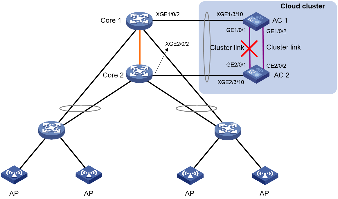
Procedure
1. Configure AC 1:
# Display information about the physical cluster.
<AC1> display cloud-cluster
Manager list:
Member ID Role Member IP State Heartbeat(ms)
1 Follower 1.1.2.11 offline --
2 Follower 1.1.2.12 offline --
Worker list:
Member ID State Heartbeat(ms) Joined at
1 offline -- --
2 offline -- --
The output shows that both AC 1 and AC 2 are followers.
# Display detailed information about all containers in the container cluster.
<Sysname> display cloud-cluster service-cluster container verbose
Service-cluster name: System
Domain ID : 1
Cluster Bridge MAC: 00e0-fc00-1001
Container ID : 1
Member ID : 1
Slot ID : 1
Health : Healthy(0)
Bridge MAC : 00e0-fc00-1001
CPU MAC : 00f0-fc00-1001
Control links: GigabitEthernet1/0/1(DOWN)
Data links : GigabitEthernet1/0/1(DOWN)
Cluster connection : Unreachable
Status : Offline
Self hello timeout (ms) : 4000
Master hello timeout (ms): 4000
Container ID : 2
Member ID : 2
Slot ID : 2
Health : Normal(0)
Bridge MAC : 00e0-fc00-1002
CPU MAC : 00f0-fc00-1002
Ctrl port : GigabitEthernet2/0/1(DOWN)
Data port : GigabitEthernet2/0/1(DOWN)
Cluster connection : Unreachable
Status : Offline
Self hello timeout (ms) : 4000
Master hello timeout (ms): 4000
# Bind GigabitEthernet 1/0/2 to both the control and data channels.
<AC1> system-view
[AC1] cloud-cluster member 1
[AC1-ccluster-member-1] cluster-link bind interface gigabitethernet 1/0/2
The system will shut down and then bring up the interface after activation the c
loud cluster configuration. Continue? [Y/N]: y
# Activate the cloud cluster configuration.
[AC1] cloud-cluster configuration active
New cluster configuration:
cloud-cluster service-cluster domain 0
cloud-cluster hello cloud-timeout 7 service-timeout 10
cloud-cluster member 1
member-ip 192.168.10.10/24
join-cluster ip 192.168.10.10
role manager-worker
cluster-link bind interface GigabitEthernet 1/0/2
The system will activate and save the configuration, and it might do a restart.Continue? [Y/N]:y
The current configuration will be written to the device. Are you sure? [Y/N]:y
Please input the file name(*.cfg)[flash:/startup.cfg]
(To leave the existing filename unchanged, press the enter key):
flash:/startup.cfg exists, overwrite? [Y/N]:y
Validating file. Please wait...
Saved the current configuration to mainboard device successfully.
2. Configure AC 2:
# Connect GigabitEthernet 1/0/2 on AC 1 to GigabitEthernet 2/0/2 on AC 2.
# Bind GigabitEthernet 2/0/2 to both the control and data channels.
<AC2> system-view
[AC2] cloud-cluster member 2
[AC2-ccluster-member-2] cluster-link bind interface GigabitEthernet 2/0/2
The system will shut down and then bring up the interface after activation the c
loud cluster configuration. Continue? [Y/N]: y
[AC2-ccluster-member-1] quit
# Activate the cloud cluster configuration.
[AC2] cloud-cluster configuration active
New cluster configuration:
cloud-cluster service-cluster domain 0
cloud-cluster hello cloud-timeout 7 service-timeout 10
cloud-cluster member 2
member-ip 192.168.10.11/24
join-cluster ip 192.168.10.10
role manager-worker
cluster-link bind interface GigabitEthernet 2/0/2
The system will activate and save the configuration, and it might do a restart. Continue? [Y/N]:y
The current configuration will be written to the device. Are you sure? [Y/N]:y
Please input the file name(*.cfg)[flash:/startup.cfg]
(To leave the existing filename unchanged, press the enter key):
flash:/startup.cfg exists, overwrite? [Y/N]:y
Validating file. Please wait...
Saved the current configuration to mainboard device successfully.
The cluster recovers after the reboot of AC 2.
Verifying the configuration
# Display information about the physical cluster.
<AC1> display cloud-cluster
Manager list:
Member ID Role Member IP State Heartbeat(ms)
1 Leader 192.168.10.10 online 100
2 Follower 192.168.10.11 online 0
Worker list:
Member ID State Heartbeat(ms) Joined at
1 online 100 2023-02-12 06:13:28
2 online 200 2023-02-12 06:13:28
The output shows that the physical cluster has two member devices. AC 1 is the leader and AC 2 is the follower.
# Display information about the container cluster.
<AC1> display cloud-cluster service-cluster container
Container ID Slot ID Member ID Role Status
*+1 1 1 Master Online
2 2 2 Standby Online
---------------------------------------------------------------
* indicates the device is the master.
+ indicates the device through which the user logs in.
The output shows that the container on AC 1 is the primary and the container on AC 2 is the secondary.
Example: Migrating a physical device to another cloud cluster
Network configuration
As shown in Figure 29, migrate Device B from Cloud cluster A to Cloud cluster B.
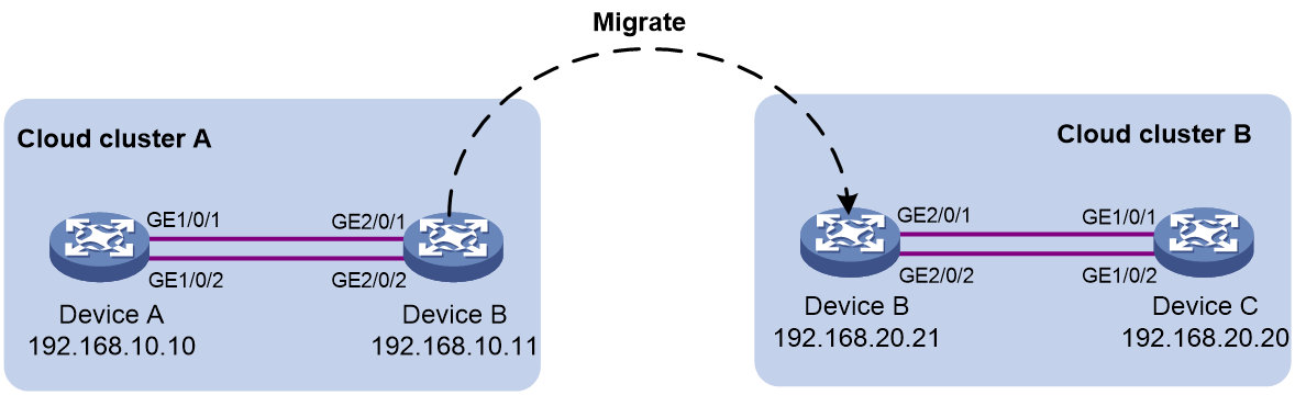
Procedure
1. Configure Device B:
# Log in to Cloud cluster A to isolate Device B from Cloud cluster A.
<Sysname> system-view
[Sysname] cloud-cluster member 2
[Sysname-ccluster-member-2] undo join-cluster
[Sysname-ccluster-member-2] quit
[Sysname] cloud-cluster configuration active
New cluster configuration:
cloud-cluster service-cluster domain 0
cloud-cluster hello cloud-timeout 7 service-timeout 10
cloud-cluster member 2
member-ip 192.168.10.11/24
join-cluster ip 192.168.10.10
role manager-worker
cloud-cluster member 2
role manager-worker
cluster-link control bind interface GigabitEthernet 2/0/1
cluster-link data bind interface Ten-GigabitEthernet 2/0/2
The system will activate and save the configuration, and it might do a restart. Continue? [Y/N]:y
The current configuration will be written to the device. Are you sure? [Y/N]:y
Please input the file name(*.cfg)[flash:/startup.cfg]
(To leave the existing filename unchanged, press the enter key):test.cfg
Validating file. Please wait...
Saved the current configuration to mainboard device successfully.
Device B operates alone after the reboot.
# Connect Gigabitethernet 2/0/1 on Device B to Gigabitethernet 1/0/1 on Device C and Gigabitethernet 2/0/2 on Device B to Gigabitethernet 1/0/2 on Device C to migrate Device B to Cloud cluster B.
# Specify the member IP address for Device B in Cloud cluster B. Make sure the member IP addresses of Device B and Device C reside on the same network segment.
<Sysname> system-view
[Sysname] cloud-cluster member 2
[Sysname-ccluster-member-2] member-ip 192.168.20.21 24
# Configure the IP address of Device B to be added to the cluster as the member IP address of AC 2.
[Sysname-ccluster-member-1] join-cluster ip 192.168.20.20
# Bind GigabitEthernet 2/0/1 to the control channel and Gigabitethernet 2/0/2 to the data channel.
[Sysname-ccluster-member-1] cluster-link control bind interface gigabitethernet 2/0/1
The system will shut down and then bring up the interface after activation the cloud cluster configuration. Continue? [Y/N]: y
[Sysname-ccluster-member-1] cluster-link data bind interface ten-gigabitethernet 2/0/2
The system will shut down and then bring up the interface after activation the cloud cluster configuration. Continue? [Y/N]: y
[Sysname-ccluster-member-1] quit
# Activate the cloud cluster configuration.
[Sysname] cloud-cluster configuration active
New cluster configuration:
cloud-cluster service-cluster domain 0
cloud-cluster hello cloud-timeout 7 service-timeout 10
cloud-cluster member 2
member-ip 192.168.20.21/24
join-cluster ip 192.168.20.20
role manager-worker
cluster-link control bind interface GigabitEthernet 2/0/1
cluster-link data bind interface GigabitEthernet 2/0/2
The system will activate and save the configuration, and it might do a restart. Continue? [Y/N]:y
The current configuration will be written to the device. Are you sure? [Y/N]:y
Please input the file name(*.cfg)[flash:/startup.cfg]
(To leave the existing filename unchanged, press the enter key):test.cfg
Validating file. Please wait...
Saved the current configuration to mainboard device successfully.
The cloud cluster configuration takes effect after the reboot. Device B is automatically added to Cloud cluster B.
Verifying the configuration
# Display information about the physical cluster.
<Sysname> display cloud-cluster
Manager list:
Member ID Role Member IP State Heartbeat(ms)
1 Leader 192.168.20.20 online 100
2 Follower 192.168.20.21 online 0
Worker list:
Member ID State Heartbeat(ms) Joined at
1 online 100 2023-02-12 06:13:28
2 online 200 2023-02-12 06:13:28
The output shows that the physical cluster has two member devices. Device C is the leader and Device B is the follower.
# Display information about the container cluster.
<Sysname> display cloud-cluster service-cluster container
Container ID Slot ID Member ID Role Status
*+1 1 1 Master Online
2 2 2 Standby Online
---------------------------------------------------------------
* indicates the device is the master.
+ indicates the device through which the user logs in.
The output shows that the container on Device C is the primary and the container on Device B is the secondary.
