- Table of Contents
- Related Documents
-
| Title | Size | Download |
|---|---|---|
| 02-Appendix | 9.93 MB |
Contents
Appendix A Server specifications
Server models and chassis view
Front panel view of the server
Appendix B Component specifications
DRAM DIMM rank classification label
Front 8SFF SAS/SATA drive backplane
Front 8SFF UniBay drive backplane
Front 8LFF SAS/SATA drive backplane
Front 12LFF SAS/SATA drive backplane
Front 12LFF drive backplane (8 SAS/SATA + 4 UniBay)
Front 12LFF drive backplane (4 SAS/SATA + 8 UniBay)
Front 12LFF UniBay drive backplane
Front 25SFF UniBay drive backplane
Front 25SFF drive backplane (17SAS/SATA+8UniBay)
Mid 4LFF SAS/SATA drive backplane
Mid 4SFF UniBay drive backplane
Rear 2LFF SAS/SATA drive backplane
Rear 4LFF SAS/SATA drive backplane
Rear 2SFF SAS/SATA drive backplane
Rear 2SFF UniBay drive backplane
Rear 4SFF SAS/SATA drive backplane
Rear 4SFF UniBay drive backplane
Rear 2SFF UniBay drive backplane (for OCP adapter)
RC-5HHHL-R5-2U-G5 (mid GPU adapter)
Appendix C Hot swapping and managed hot removal of NVMe drives
Performing a hot removal in Windows
Performing a hot removal in Linux
Performing a hot removal in VMware
Performing a managed hot removal in Windows
Performing a managed hot removal in Linux
Performing a hot installation in Windows
Performing a hot installation in Linux
Performing a hot installation in VMware
Verifying the RAID status of the installed NVMe drive
Appendix D Managed removal of OCP network adapters
Appendix E Environment requirements
About environment requirements
General environment requirements
Operating temperature requirements
8SFF and 16SFF drive configuration
12LFF, 25SFF, and 24SFF drive configuration
Appendix A Server specifications
The information in this document might differ from your product if it contains custom configuration options or features.
Figures in this document are for illustration only.
Server models and chassis view
H3C UniServer R4900 G5 servers are 2U rack servers with two Intel Ice Lake series processors. They are suitable for cloud computing, IDC, and enterprise networks built based on new generation infrastructure. The servers feature low power consumption, high availability, and strong expandability, allowing for simple deployment and management.
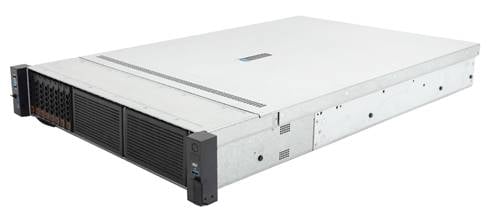
The servers come in the models listed in Table 1. These models support different drive configurations.
Table 1 R4900 G5 server models
|
Model |
Maximum drive configuration |
|
LFF |
12 LFF drives at the front + 4 LFF, 4SFF drives at the rear + 4 LFF drives in the middle. |
|
SFF |
25 SFF drives at the front + 4 LFF drives and 4 SFF drives at the rear + 8 SFF drives in the middle. |
Technical specifications
|
Item |
Specifications |
|
Dimensions (H × W × D) |
· Without a security bezel: 87.5 × 445.4 × 748 mm (3.44 × 17.54 × 29.45 in) · With a security bezel: 87.5 × 445.4 × 776 mm (3.44 × 17.54 × 30.55 in) |
|
Max. weight |
42.1 kg (92.81 lb) |
|
Power consumption |
The power consumption varies by configuration. For more information, use the server power consumption lookup tool. |
|
Processors |
· 2 ×Intel Ice Lake processors: ¡ A maximum of 270 W power consumption per processor. ¡ Processor-integrated memory controller, supporting 8 memory channels. ¡ Processor-integrated PCIe controller, supporting PCIe 4.0 and providing 64 PCIe lanes per processor. ¡ 3-way UPI bus interconnection, with each link providing a transmission rate of up to 11.2 GT/s. · For more processor information, see the server-compatible components lookup tool. |
|
Memory |
A maximum of 32 DIMMs Supports DDR4 and PMem 200 DIMMs |
|
Storage controllers |
· Embedded VROC storage controller · High-performance standard storage controller · NVMe VROC module · Dual SD card extended module (supports RAID 1) |
|
Chipset |
Intel C621A Lewisburg chipset |
|
Integrated graphics card |
The graphics card chip is integrated into the BMC chip, which is the AST2500 model. It provides 64MB video memory and supports a maximum resolution of 1920 x 1200 @ 60Hz (32 bits per pixel). · Resolution: ¡ 1920 x 1200: 1920 pixel columns horizontally and 1200 pixel columns vertically. ¡ 60Hz: The screen refreshes 60 times per second. ¡ 32bpp: Color depth. Higher color depth provides richer color representation. · The integrated graphics card can support a maximum resolution of 1920 x 1200 pixels only after a graphics card driver compatible with the operating system is installed. If no such a graphics card driver is installed, the server supports only the default resolution of the operating system. · When both the front and rear VGA connectors are connected to monitors, only the monitor connected to the front VGA connector displays. |
|
Network connectors |
· 1 × embedded 1 Gbps HDM dedicated port · A maximum of 2 OCP 3.0 network adapter connectors (for NCSI-capable OCP 3.0 network adapters) |
|
I/O connectors |
· 6 × USB connectors (two on the system board, two at the server rear, and two at the server front) · 12 × embedded SATA connectors: ¡ One ×8 SlimSAS connector ¡ One ×4 SlimSAS connector · 4 × embedded LP SlimSAS connectors (PCIe4.0 x8) · 1 × RJ-45 HDM dedicated port (at the server rear) · 2 × VGA connectors (one at the server rear and one at the server front) · 1 ×serial port (at the server rear) · 1 × dedicated HDM management interface (at the server front) |
|
Expansion slots |
14 × PCIe 4.0 slots |
|
Optical drives |
External USB optical drives |
|
Management |
· HDM agentless management tool with a dedicated management port · H3C iFIST/UniSystem management software · LCD smart management module · Supports 64M of local video memory · Supports optional U-Center data center management platform |
|
Security |
· Supports secure enclosure · Supports TCM/TPM security module · Supports two-factor authentication |
|
Power supplies |
2 × hot-swappable power supplies, 1 + 1 redundancy |
|
Standards |
CCC, CECP, SEPA |
Components
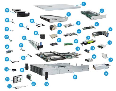
Figure 2 R4900 G5 server components
|
Item |
Description |
|
(1) Chassis access panel |
N/A |
|
(2) Mid drive cage |
Provides a drive slot for storage expansion. |
|
(3) Mid GPU adapter |
Provides a GPU slot for graphics processing and AI services. |
|
(4) Processor heatsink |
Cools the processor. |
|
(5) OCP network adapter |
Installed on the OCP slot on the system board. |
|
(6) Standard PCIe network adapter |
Installed in a standard PCIe slot to provide network ports. |
|
(7) Riser card |
Provides PCIe slots. |
|
(8) GPU module |
Provides computing services such as graphics processing and AI. |
|
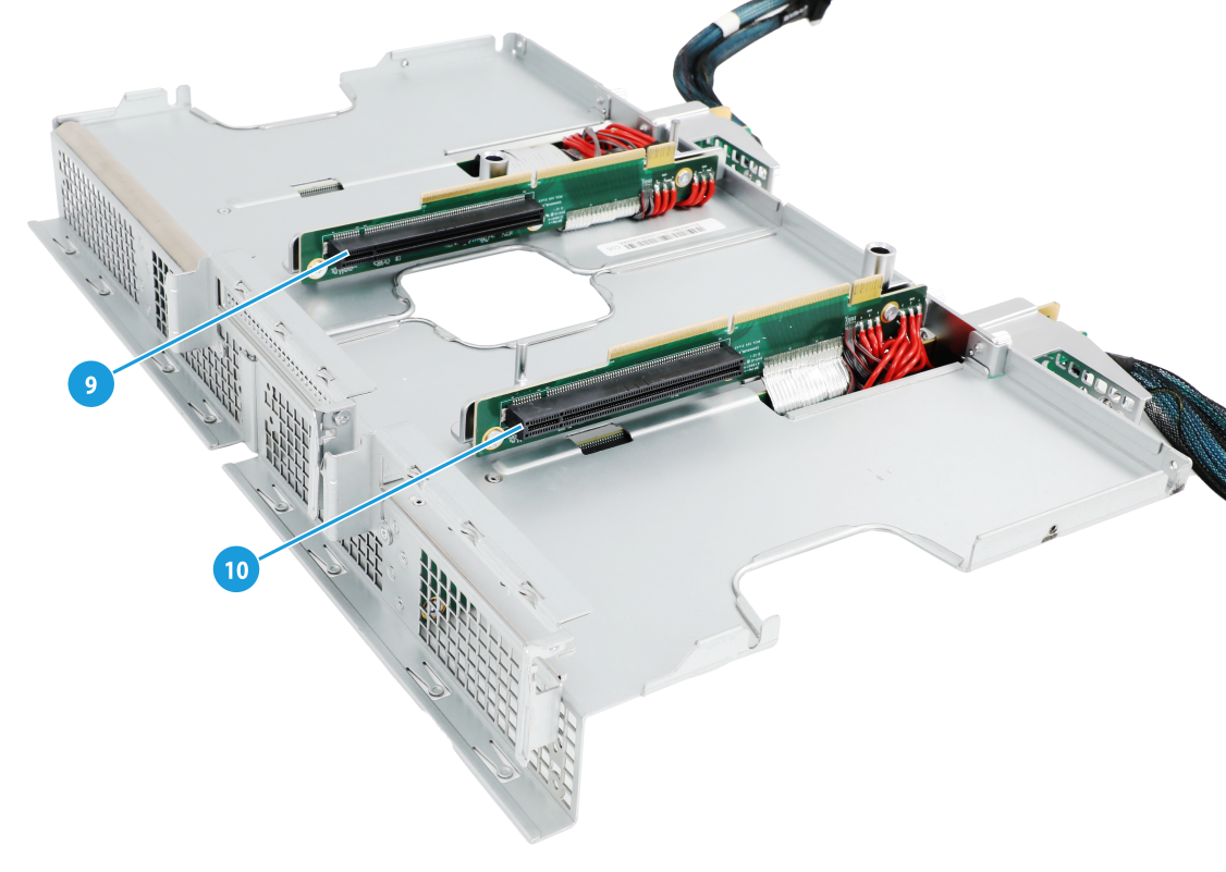
(9) Storage controller |
Provides RAID capability to SAS/SATA drives, including RAID configuration and RAID scale-up. It supports online upgrade of the controller firmware and remote configuration. |
|
(10) Processor |
Integrates memory and PCIe controllers to provide data processing capabilities for the server. |
|
(11) Processor socket cover |
Installed over an empty processor socket to protect pins in the socket. |
|
(12) Memory |
Stores computing data and data exchanged with external storage temporarily. The server supports DDR4 and PMem200 memory. |
|
(13) System board |
One of the most important parts of a server, on which multiple components are installed, such as processor, memory, and fan. It is integrated with basic server components, including the BIOS chip and PCIe connectors. |
|
(14) Rear drive backplane |
Provides power and data channels for drives at the server rear. This guide uses the 4SFF drive backplane at the rear as an example. |
|
(15) OCP adapter |
Provides one slot for installing an OCP network adapter and two slots for installing drives at the server rear. |
|
(16) Rear drive cage |
Encloses drives at the server rear. |
|
(17) Riser card blank |
Installed on an empty PCIe riser connector to ensure good ventilation. |
|
(18) Power supply |
Supplies power to the server. The power supplies support hot swapping and 1+1 redundancy. |
|
(19) Chassis |
N/A |
|
(20) Chassis ears |
Attach the server to the rack. The right ear is integrated with the front I/O component, and the left ear is integrated with VGA connector, HDM dedicated management connector, and USB 3.0 connector. |
|
(21) Front drive backplane |
Provides power and data channels for drives at the server front. This guide uses the 8SFF drive backplane at the front as an example. |
|
(22) LCD smart management module |
Displays basic server information, operating status, and fault information. Together with HDM event logs, users can fast locate faulty components and troubleshoot the server, ensuring server operation. |
|
(23) Drive |
Provides data storage space. Drives support hot swapping. The server supports SSDs and HDDs and various types of drive interfaces, including SAS, SATA, M.2, and PCIe. |
|
(24) Supercapacitor holder |
Secures a supercapacitor in the chassis. |
|
(25) Supercapacitor |
Supplies power to the flash card on the power fail safeguard module, which enables the storage controller to back up data to the flash card for protection when power outage occurs. |
|
(26) Dual SD card expander module |
Provides two SD card slots. |
|
(27) Encryption module |
Provides encryption services for the server to enhance data security. |
|
(28) System battery |
Supplies power to the system clock to ensure system time correctness. |
|
(29) Chassis open-alarm module |
Detects if the access panel is removed. The detection result can be displayed from the HDM Web interface. |
|
(30) Air baffle |
Provides ventilation aisles for processor heatsinks and memory modules and provides support for the supercapacitor. |
|
(31) Processor retaining bracket |
Attaches a processor to the heatsink. |
|
(32) NVMe VROC module |
Works with Intel VMD to provide RAID capability for the server to virtualize storage resources of NVMe drives. |
|
(33) Fan |
Helps server ventilation. Fans support hot swapping and N+1 redundancy. |
|
(34) Fan cage |
Accommodates fans. |
|
(35) SATA M.2 SSD |
Provides data storage space for the server. |
|
(36) SATA M.2 SSD expander module |
Provides M.2 SSD slots. |
Front panel
Front panel view of the server
Figure 3 8LFF front panel
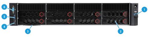
Table 2 8LFF front panel description
|
Item |
Description |
|
1 |
USB 3.0 connector |
|
2 |
LCD smart management module (optional) |
|
3 |
Serial label pull tab |
|
4 |
HDM dedicated management connector |
|
5 |
USB 3.0 connector |
|
6 |
VGA connector |
Figure 4 12LFF front panel
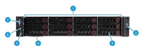
Table 3 12LFF front panel description
|
Item |
Description |
|
1 |
UniBay drives (for the 12LFF UniBay drive configuration) |
|
2 |
USB 3.0 connector |
|
3 |
LCD smart management module (optional) |
|
4 |
Serial label pull tab |
|
5 |
HDM dedicated management connector |
|
6 |
USB 3.0 connector |
|
7 |
VGA connector |
|
|
NOTE: Drives supported by the server vary by drive backplane. For more information about drive backplanes, see "Drive backplanes." |
Figure 5 8SFF front panel
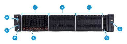
Table 4 8SFF front panel description
|
Item |
Description |
|
1 |
Bay 1 for 8SFF drives (optional) |
|
2 |
Bay 2 for 8SFF drives (optional) |
|
3 |
Bay 3 for 8SFF drives (optional) |
|
4 |
USB 3.0 connector |
|
5 |
LCD smart management module (optional) |
|
6 |
Serial label pull tab |
|
7 |
HDM dedicated management connector |
|
8 |
USB 3.0 connector |
|
14 |
VGA connector |
|
|
NOTE: A drive backplane is required if you install SAS/SATA or UniBay drives. For more information about drive backplanes, see "Drive backplanes." |
Figure 6 25SFF front panel
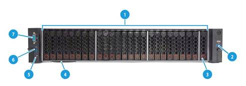
Table 5 25SFF front panel description
|
Item |
Description |
|
1 |
25SFF drives |
|
2 |
USB 3.0 connector |
|
3 |
Drive or LCD smart management module (optional) |
|
4 |
Serial label pull tab |
|
5 |
HDM dedicated management connector |
|
6 |
USB 3.0 connector |
|
7 |
VGA connector |
|
|
NOTE: A drive backplane is required if you install SAS/SATA or UniBay drives. For more information about drive backplanes, see "Drive backplanes." |
LEDs and buttons
The LED and buttons are the same on all server models. Figure 7 shows the front panel LEDs and buttons. Table 6 describes the status of the front panel LEDs.
Figure 7 Front panel LEDs and buttons
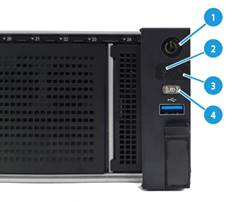
Table 6 LEDs and buttons on the front panel
|
Button/LED |
Status |
|
Power on/standby button and system power LED |
· Steady green—The system has started. · Flashing green (1 Hz)—The system is starting. · Steady amber—The system is in standby state. · Off—No power is present. Possible reasons: ¡ No power source is connected. ¡ No power supplies are present. ¡ The installed power supplies are faulty. ¡ The system power cords are not connected correctly. |
|
OCP network adapter Ethernet port LED |
· Steady green—A link is present on a port of an OCP 3.0 network adapter. · Flashing green (1 Hz)—A port of an OCP 3.0 network adapter is receiving or sending data. · Off—No link is present on all ports of all OCP 3.0 network adapters. A server supports a maximum of two OCP 3.0 network adapters. |
|
Health LED |
· Steady green—The system is operating correctly or a minor alarm is present. · Flashing green (4 Hz)—HDM is initializing. · Flashing amber (1 Hz)—A major alarm is present. · Flashing red (1 Hz)—A critical alarm is present. If a system alarm is present, log in to HDM to obtain more information about the system running status. |
|
UID button LED |
· Steady blue—UID LED is activated. The UID LED can be activated by using the following methods: ¡ Press the UID button LED. ¡ Activate the UID LED from HDM. · Flashing blue: ¡ 1 Hz—The firmware is being upgraded or the system is being managed from HDM. Do not power off the server. ¡ 4 Hz—HDM is restarting. To restart HDM, press the UID button LED for eight seconds. · Off—UID LED is not activated. |
Security bezel light
The security bezel provides hardened security and uses effect light to visualize operation and health status to help inspection and fault location. The default effect light is as shown in Figure 8.
Table 7 Security bezel effect light
|
System status |
Light status |
|
Standby |
Steady white: The system is in standby state. |
|
Startup |
· Beads turn on white from middle in turn—POST progress. · Beads turn on white from middle three times—POST has finished. |
|
Running |
· Breathing white (gradient at 0.2 Hz)—Normal state, indicating the system load by the percentage of beads turning on from the middle to the two sides of the security bezel. ¡ No load—Less than 10%. ¡ Light load—10% to 50%. ¡ Middle load—50% to 80%. ¡ Heavy load—More than 80%. · Breathing white (gradient at 1 Hz )—A pre-alarm is present. · Flashing amber (1 Hz)—A major alarm is present. · Flashing red (1 Hz)—A critical alarm is present. |
|
Remote management |
· All beads flash white (1 Hz)—The firmware is being upgraded or the system is being managed from HDM. Do not power off the server. · Some beads flash white (1 Hz)—HDM is restarting. |
Ports
Table 8 Ports on the front panel
|
Port |
Type |
Description |
|
VGA connector |
DB-15 |
Connects a display terminal, such as a monitor or KVM device. |
|
USB connector |
USB 3.0 |
Connects the following devices: · USB flash drive. · USB keyboard or mouse. · USB optical drive for operating system installation. |
|
HDM dedicated management connector |
Type-C |
Connects a Type-C to USB adapter cable, which connects to a USB Wi-Fi adapter or USB drive. |
Rear panel
Rear panel view
Figure 9 shows the rear panel view.
Figure 9 Rear panel components
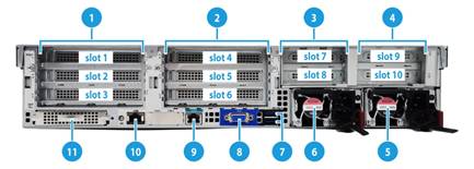
Table 9 Rear panel description
|
Item |
Description |
|
|
1 |
PCIe riser bay 1: PCIe slots 1 through 3 |
|
|
2 |
PCIe riser bay 2: PCIe slots 4 through 6 |
|
|
3 |
PCIe riser bay 3: PCIe slots 7 and 8 |
|
|
4 |
PCIe riser bay 4: PCIe slots 9 and 10 |
|
|
5 |
Power supply 2 |
|
|
6 |
Power supply 1 |
|
|
7 |
Two USB 3.0 connectors |
|
|
8 |
VGA connector |
|
|
9 |
BIOS serial port |
|
|
10 |
HDM dedicated network port (1Gbps, RJ-45, default IP address 192.168.1.2/24) |
|
|
11 |
OCP 3.0 network adapter (in slot 16)(optional) |
|
LEDs
Figure 10 shows the rear panel LEDs. Table 10 describes the status of the rear panel LEDs.
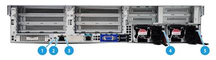
|
(1) UID LED |
(2) Link LED of the Ethernet port |
|
(3) Activity LED of the Ethernet port |
(4) Power supply LED for power supply 1 |
|
(5) Power supply LED for power supply 2 |
|
Table 10 LEDs on the rear panel
|
LED |
Status |
|
UID LED |
· Steady blue—UID LED is activated. The UID LED can be activated by using the following methods: ¡ Press the UID button LED. ¡ Enable UID LED from HDM. · Flashing blue: ¡ 1 Hz—The firmware is being upgraded or the system is being managed from HDM. Do not power off the server. ¡ 4 Hz—HDM is restarting. To restart HDM, press the UID button LED for eight seconds. · Off—UID LED is not activated. |
|
Link LED of the Ethernet port |
· Steady green—A link is present on the port. · Off—No link is present on the port. |
|
Activity LED of the Ethernet port |
· Flashing green (1 Hz)—The port is receiving or sending data. · Off—The port is not receiving or sending data. |
|
Power supply LED |
· Steady green—The power supply is operating correctly. · Flashing green (1 Hz)—Power is being input correctly but the system is not powered on. · Flashing green (0.33 Hz)—The power supply is in standby state and does not output power. · Flashing green (2 Hz)—The power supply is updating its firmware. · Steady amber—Either of the following conditions exists: ¡ The power supply is faulty. ¡ The power supply does not have power input, but another power supply has correct power input. · Flashing amber (1 Hz)—An alarm has occurred on the power supply. · Off—No power supplies have power input, which can be caused by an incorrect power cord connection or power source shutdown. |
Ports
Table 11 Ports on the rear panel
|
Port |
Type |
Description |
|
VGA connector |
DB-15 |
Connects a display terminal, such as a monitor or KVM device. |
|
BIOS serial port |
RJ-45 |
The BIOS serial port is used for the following purposes: · Log in to the server when the remote network connection to the server has failed. · Establish a GSM modem or encryption lock connection. |
|
USB connector |
USB 3.0 |
Connects the following devices: · USB flash drive. · USB keyboard or mouse. · USB optical drive for operating system installation. |
|
HDM dedicated network port |
RJ-45 |
Establishes a network connection to manage HDM from its Web interface. |
|
Power receptacle |
Standard single-phase |
Connects the power supply to the power source. |
System board
System board components
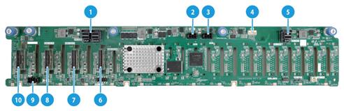
Figure 11 shows the system board layout.
Figure 11 System board components
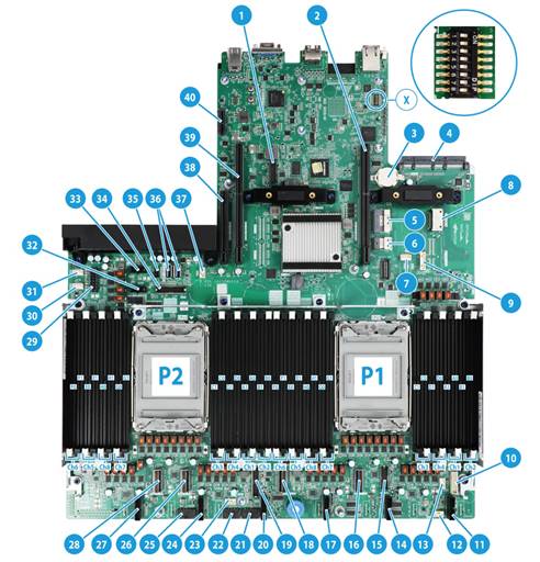
Table 12 System board components
|
Item |
Description |
|
1 |
TPM/TCM connector (TPM) |
|
2 |
PCIe riser connector 1 (for processor 1) (RISER1 PCIe X32) |
|
3 |
System battery |
|
4 |
OCP 3.0 adapter connector (OCP3.0) |
|
5 |
SlimSAS port 1 (×8 SATA) (SATA PORT) |
|
6 |
SlimSAS port 2 (×4 SATA) (SSATA PORT) |
|
7 |
Rear drive backplane AUX connector 9 (AUX9) |
|
8 |
GenZ port (×2 SATA) (M.2&CD-ROM) |
|
9 |
AUX connector 7 (AUX7) |
|
10 |
LCD smart management module connector (DIAGLCD) |
|
11 |
Fan connector 6 (J66) |
|
12 |
Drive backplane AUX connector 3 (AUX3) |
|
13 |
Drive backplane AUX connector 2 (AUX2) |
|
14 |
Fan connector 5 (J65) |
|
15 |
Front I/O connector (RIGHT EAR) |
|
16 |
LP SlimSAS port A1/A2 (PCIe4.0 x8, for processor 1) (NVMe-A1/A2) |
|
17 |
Fan connector 4 (reserved) (J64) |
|
18 |
LP SlimSAS port A3/A4 (PCIe4.0 x8, for processor 1) (NVMe-A3/A4) |
|
19 |
Chassis-open alarm module, front VGA, and USB 3.0 connector (LEFT EAR) |
|
20 |
Fan connector 3 (J63) |
|
21 |
Drive backplane power connector 3 (PWR3) |
|
22 |
Drive backplane power connector 1 (PWR1) |
|
23 |
Drive backplane AUX connector 1 (AUX1) |
|
24 |
Fan connector 2 (J62) |
|
25 |
Drive backplane power connector 2 (PWR2) |
|
26 |
LP SlimSAS port B1/B2 (PCIe4.0 x8, for processor 2) (NVMe-B1/B2) |
|
27 |
Fan connector 1 (reserved) (J61) |
|
28 |
LP SlimSAS port B3/B4 (PCIe4.0 x8, for processor 2) (NVMe-B3/B4) |
|
29 |
Power connector 6 (PWR6) |
|
30 |
Drive backplane AUX connector 5 (AUX5) |
|
31 |
Drive backplane AUX connector 4 (AUX4) |
|
32 |
Power connector 5 (PWR5) |
|
33 |
Drive backplane power connector 4 (PWR4) |
|
34 |
AUX connector 8 (AUX8) |
|
35 |
NVMe VROC module connector (NVMe RAID KEY) |
|
36 |
Two USB 3.0 connectors (INTERNAL USB3.0 PORT1/ INTERNAL USB3.0 PORT2) |
|
37 |
Drive backplane AUX connector 6 (AUX6) |
|
38 |
PCIe riser connector 3 (for processor 2) (RISER3 PCIe X16) |
|
39 |
PCIe riser connector 2 (for processor 2) (RISER2 PCIe X32) |
|
40 |
Dual SD card extended module connector (DSD CARD) |
|
X |
System maintenance switch |
|
PCIe4.0 x8 description: · PCIe4.0: Fourth-generation signal speed. · x8: Bus bandwidth. |
|
System maintenance switch
Figure 12 shows the system maintenance switch. Table 13 describes how to use the maintenance switch.
Figure 12 System maintenance switch
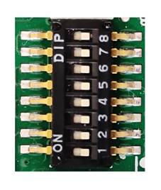
Table 13 System maintenance switch description
|
Item |
Description |
Remarks |
|
1 |
· Off (default)—HDM login requires the username and password of a valid HDM user account. · On—HDM login requires the default username and password. |
For security purposes, turn off the switch after you complete tasks with the default username and password as a best practice. |
|
5 |
· Off (default)—Normal server startup. · On—Restores the default BIOS settings. |
To restore the default BIOS settings, turn on and then turn off the switch. The server starts up with the default BIOS settings at the next startup.
The server cannot start up when the switch is turned on. To avoid service data loss, stop running services and power off the server before turning on the switch. |
|
6 |
· Off (default)—Normal server startup. · On—Clears all passwords from the BIOS at server startup. |
If this switch is on, the server will clear all the passwords at each startup. Make sure you turn off the switch before the next server startup if you do not need to clear all the passwords. |
|
2, 3, 4, 7, and 8 |
Reserved for future use. |
N/A |
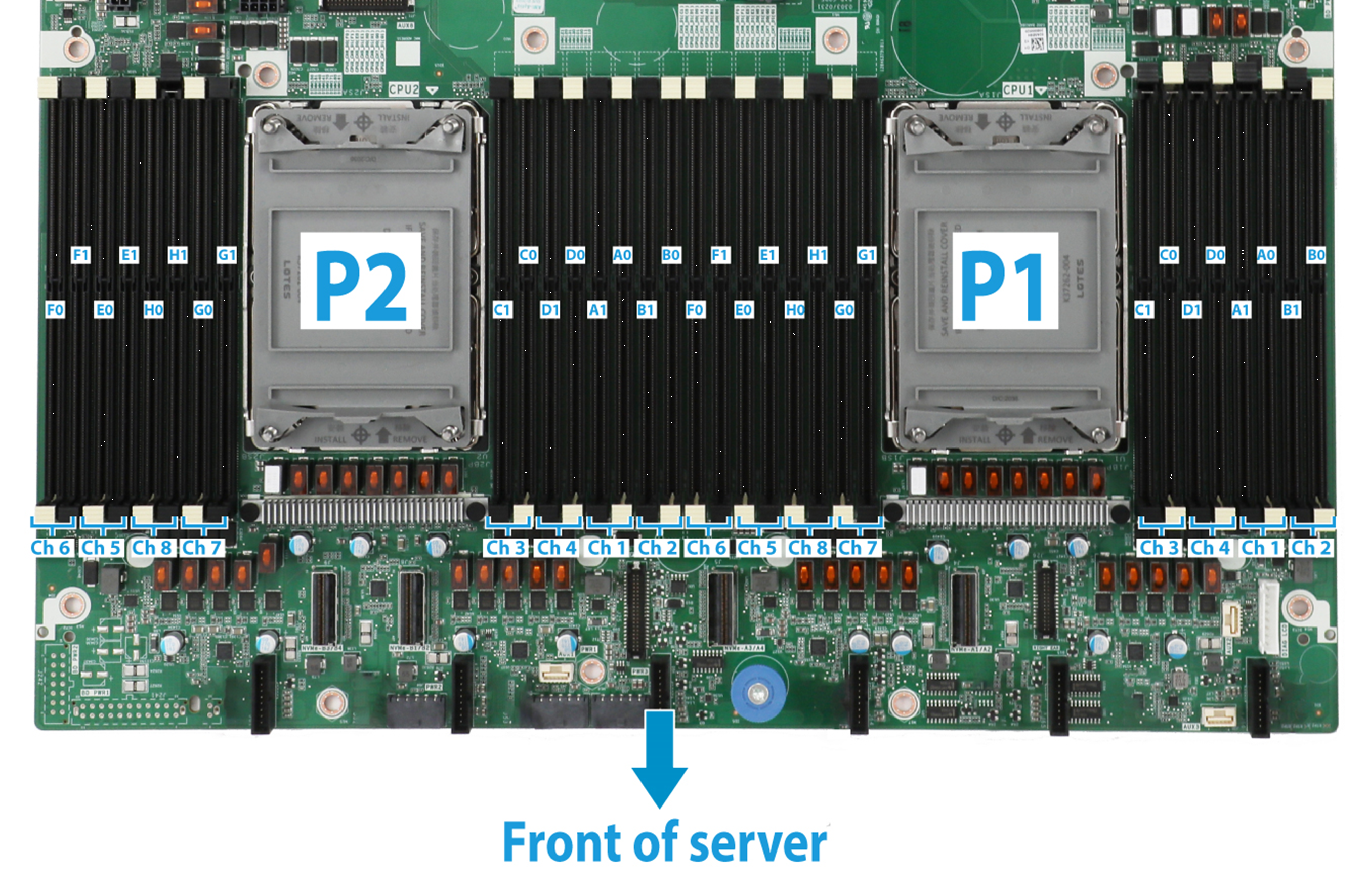
DIMM slots
The system board and processor mezzanine board each provide six DIMM channels per processor, and 12 channels in total, as shown in Figure 13. Each channel contains two DIMM slots.
Figure 13 System board DIMM slot layout
Appendix B Component specifications
For components compatible with the server and detailed component information, visit the query tool at http://www.h3c.com/cn/Service/Document_Software/Document_Center/Server/.
About component model names
The model name of a hardware option in this document might differ slightly from its model name label.
A model name label might add a prefix or suffix to the hardware-coded model name for purposes such as identifying the matching server brand or applicable region. For example, the DDR4-3200-16G-2Rx8-R memory model represents memory module labels including UN-DDR4-3200-16G-2Rx8-R, UN-DDR4-3200-16G-2Rx8-R-F, and UN-DDR4-3200-16G-2Rx8-R-S, which have different prefixes and suffixes.
DIMMs
The server provides eight DIMM channels per processor and each channel has two DIMM slots. If the server has one processor, the total number of DIMM slots is 16. If the server has two processors, the total number of DIMM slots is 32.
DRAM DIMM rank classification label
|
|
NOTE: For the label description, functions, and advantages of PMem 200, see H3C Servers PMem 200 User Guide. |
A DIMM rank is a set of memory chips that the system accesses while writing or reading from the memory. On a multi-rank DIMM, only one rank is accessible at a time.
To determine the rank classification of a DRAM DIMM, use the label attached to the DIMM, as shown in Figure 14.
Figure 14 DRAM DIMM rank classification label
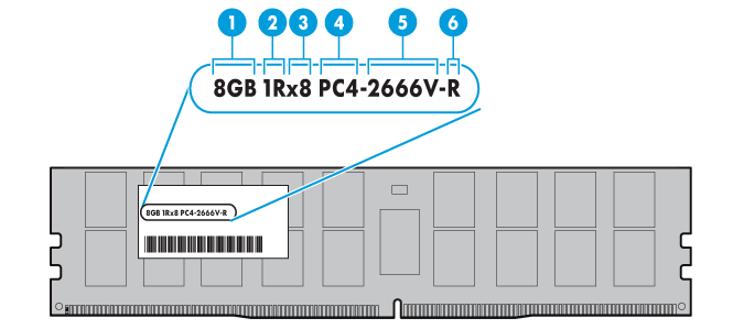
Table 14 DIMM rank classification label description
|
Callout |
Description |
Remarks |
|
1 |
Capacity |
Options include: · 8GB. · 16GB. · 32GB. |
|
2 |
Number of ranks |
Options include: · 1R— One rank (Single-Rank). · 2R—Two ranks (Dual-Rank). A 2R DIMM is equivalent to two 1R DIMMs. · 4R—Four ranks (Quad-Rank). A 4R DIMM is equivalent to two 2R DIMMs · 8R—Eight ranks (8-Rank). An 8R DIMM is equivalent to two 4R DIMMs. |
|
3 |
Data width |
Options include: · ×4—4 bits. · ×8—8 bits. |
|
4 |
DIMM generation |
Only DDR4 is supported. |
|
5 |
Data rate |
Options include: · 2666V—2666 MT/s. · 2933Y—2933 MT/s. · 3200AA—3200 MT/s. |
|
6 |
DIMM type |
Options include: · L—LRDIMM. · R—RDIMM. |
HDDs and SSDs
Drive numbering
For the relationship between the physical drive numbers and their software display numbers in HDM and BIOS, see H3C UniServer R4900 G5 Server Drive Slot Number Mapping Matrixes.
The server provides different drive numbering schemes for different drive configurations at the server front and rear, as shown in Figure 15 through Figure 20.
Figure 15 Drive numbering for front 25SFF drive configurations
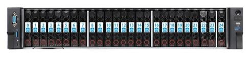
Figure 16 Drive numbering for front 12LFF drive configurations
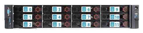
Figure 17 Drive numbering for front 8LFF drive configurations
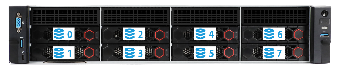
Figure 18 Drive numbering for rear 4LFF + 4SFF drive configurations
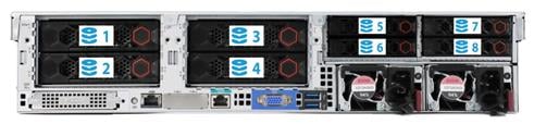
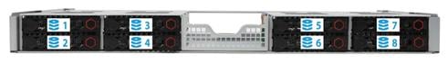
Figure 19 Drive numbering for mid 4LFF drive configurations

Figure 20 Drive numbering for mid 8SFF drive configurations
Drive LEDs
The server supports SAS, SATA, and NVMe drives, of which SAS and SATA drives support hot swapping and NVMe drives support hot insertion and managed hot removal. You can use the LEDs on a drive to identify its status after it is connected to a storage controller.
For more information about OSs that support hot insertion and managed hot removal of NVMe drives, visit the OS compatibility query tool at http://www.h3c.com/cn/Service/Document_Software/Document_Center/Server/.
Figure 21 shows the location of the LEDs on a drive.
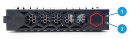
|
(1) Fault/UID LED |
(2) Present/Active LED |
To identify the status of a SAS or SATA drive, use Table 15. To identify the status of an NVMe drive, use Table 16.
Table 15 SAS/SATA drive LED description
|
Fault/UID LED status |
Present/Active LED status |
Description |
|
Flashing amber (0.5 Hz) |
Steady green/Flashing green (4.0 Hz) |
A drive failure is predicted. As a best practice, replace the drive before it fails. |
|
Steady amber |
Steady green/Flashing green (4.0 Hz) |
The drive is faulty. Replace the drive immediately. |
|
Steady blue |
Steady green/Flashing green (4.0 Hz) |
The drive is operating correctly and is selected by the RAID controller. |
|
Off |
Flashing green (4.0 Hz) |
The drive is performing a RAID migration or rebuilding, or the system is reading or writing data to the drive. |
|
Off |
Steady green |
The drive is present but no data is being read or written to the drive. |
|
Off |
Off |
The drive is not securely installed. |
Table 16 NVMe drive LED description
|
Fault/UID LED status |
Present/Active LED status |
Description |
|
Flashing amber (4 Hz) |
Off |
The drive is in hot insertion process. |
|
Steady amber |
Steady green/Flashing green (4.0 Hz) |
The drive is faulty. Replace the drive immediately. |
|
Steady blue |
Steady green/Flashing green (4.0 Hz) |
The drive is operating correctly and selected by the RAID controller. |
|
Off |
Flashing green (4.0 Hz) |
The drive is performing a RAID migration or rebuilding, or the system is reading or writing data to the drive. |
|
Off |
Steady green |
The drive is present but no data is being read or written to the drive. |
|
Off |
Off |
The drive is not securely installed. |
Drive configurations
The server supports multiple drive configurations. For more information about drive configurations and their required storage controller and riser cards, see H3C UniServer R4900 G5 Server Drive Configurations and Cabling Guide.
Drive backplanes
The server supports the following types of drive backplanes:
· SAS/SATA drive backplanes—Support only SAS/SATA drives.
· UniBay drive backplanes—Support both SAS/SATA and NVMe drives in any drive slots. You must connect both SAS/SATA and NVMe data cables. The number of supported drives varies by drive cabling.
· Drive backplane (X SAS/SATA+Y UniBay)—Support SAS/SATA in any drive slots and support NVMe drives in specific drive slots. You must connect both SAS/SATA and NVMe data cables. The number of supported drives varies by drive cabling.
¡ X: Number of slots supporting SAS/SATA drives.
¡ Y: Number of slots supporting both SAS/SATA drives and NVMe drives.
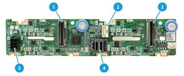
Front 8SFF SAS/SATA drive backplane
The PCA-BP-8SFF-2U-G5 8SFF SAS/SATA drive backplane can be installed at the server front to support eight 2.5-inch SAS/SATA drives.
Figure 22 8SFF SAS/SATA drive backplane
|
(1) x8 Mini-SAS-HD connector (SAS PORT 1) |
(2) AUX connector (AUX 1) |
|
(3) Power connector (PWR 1) |
|
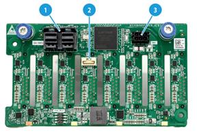
Front 8SFF UniBay drive backplane
The PCA-BP-8UniBay-2U-G5 8SFF UniBay drive backplane can be installed at the server front to support eight 2.5-inch SAS/SATA/NVMe drives.
Figure 23 8SFF UniBay drive backplane
|
(1) x8 Mini-SAS-HD connector (SAS PORT) |
(2) AUX connector (AUX) |
|
(3) SlimSAS connector A1/A2 (PCIe4.0 x8)(NVMe A1/A2) |
(4) Power connector (PWR) |
|
(5) SlimSAS connector A3/A4 (PCIe4.0 x8)(NVMe A3/A4) |
|
|
(6) SlimSAS connector B1/B2 (PCIe4.0 x8)(NVMe B1/B2) |
|
|
(7) SlimSAS connector B3/B4 (PCIe4.0 x8)(NVMe B3/B4) |
|
|
The description for PCIe4.0 x8 is as follows: · PCIe4.0: Fourth-generation signal speed. · x8: Bus bandwidth. |
|
Front 8LFF SAS/SATA drive backplane
The PCA-BP-8LFF-2U-G5 8LFF SAS/SATA drive backplane can be installed at the server front to support eight 3.5-inch SAS/SATA drives.
Figure 24 8LFF SAS/SATA drive backplane
|
(1) x8 Mini-SAS-HD connector (SAS PORT 1) |
(2) AUX connector (AUX 1) |
|
(3) Power connector (PWR 1) |
|
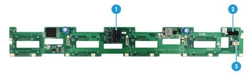
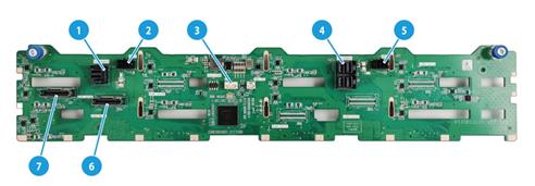
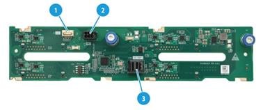
Front 12LFF SAS/SATA drive backplane
The PCA-BP-12LFF-2U-G5 12LFF SAS/SATA drive backplane can be installed at the server front to support 12 3.5-inch SAS/SATA drives.
Figure 25 12LFF SAS/SATA drive backplane
|
(1) x4 Mini-SAS-HD connector (SAS PORT 2) (controls the SAS/SATA drives in the last four slots attached to the backplane) |
|
|
(2) Power connector 2 (PWR 2) |
(3) AUX connector (AUX) |
|
(4) x8 Mini-SAS-HD connector (controls the SAS/SATA drives in the first eight slots attached to the backplane) |
|
|
(5) Power connector 1 (PWR 1) |
|
Front 12LFF drive backplane (8 SAS/SATA + 4 UniBay)
The PCA-BP-12LFF-4NVMe-2U-G5 12LFF drive backplane can be installed at the server front to support 12 3.5-inch drives, including 8 SAS/SATA drives and 4 SAS/SATA/NVMe drives.
Figure 26 12LFF drive backplane (8 SAS/SATA + 4 UniBay)
|
(1) x4 Mini-SAS-HD connector (SAS PORT 2) (controls the SAS/SATA drives in the last four slots attached to the backplane) |
|
|
(2) Power connector 2 (PWR 2) |
(3) AUX connector (AUX) |
|
(4) x8 Mini-SAS-HD connector (SAS PORT 1) (controls the SAS/SATA drives in the first eight slots attached to the backplane) |
|
|
(5) Power connector 1 (PWR 1) |
|
|
(6) SlimSAS connector B1/B2 (PCIe4.0 x8) (NVMe B1/B2) (supporting NVMe drives) (corresponds to drives numbered 8 and 9) |
|
|
(7) SlimSAS connector B3/B4 (PCIe4.0 x8) (NVMe B3/B4) (supporting NVMe drives) (corresponds to drives numbered 10 and 11) |
|
|
The description for PCIe4.0 x8 is as follows: · PCIe4.0: Fourth-generation signal speed. · x8: Bus bandwidth. For more information about drive numbering, see Figure 16. |
|
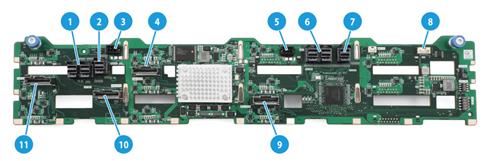
Front 12LFF drive backplane (4 SAS/SATA + 8 UniBay)
The PCA-BP-12LFF-EXP-2U-G5 12LFF drive backplane with an Expander chip can be installed at the server front to support 12 3.5-inch drives, including 4 SAS/SATA drives and 8 SAS/SATA/NVMe drives. The backplane is embedded with an Expander chip, which allows it to manage 12 SAS/SATA drives through an x8 Mini-SAS-HD port.
The backplane also provides three downlink connectors to connect to other backplanes and manage more drives.
Figure 27 12LFF drive backplane (4 SAS/SATA + 8 UniBay)
|
(1) x8 Mini-SAS-HD uplink connector (SAS PORT) (controls all drives attached to the backplane) |
|
|
(2) x4 Mini-SAS-HD downlink connector 3 (SAS EXP3) |
(3) Power connector 2 (PWR 2) |
|
(4) SlimSAS connector A3/A4 (PCIe4.0 x8) (supports NVMe drives) (corresponds to drives numbered 6 and 7) (NVMe A3/A4) |
|
|
(5) Power connector 1 (PWR 1) |
(6) x8 Mini-SAS-HD downlink connector 2 (SAS EXP2) |
|
(7) x4 Mini-SAS-HD downlink connector 1 (SAS EXP1) |
(8) AUX connector (AUX) |
|
(9) SlimSAS connector A1/A2 (PCIe4.0 x8) (NVMe A1/A2) (supports NVMe drives) (corresponds to drives numbered 4 and 5) |
|
|
(10) SlimSAS connector B1/B2 (PCIe4.0 x8) (NVMe B1/B2) (supports NVMe drives) (corresponds to drives numbered 8 and 9) |
|
|
(11) SlimSAS connector B3/B4 (PCIe4.0 x8) (NVMe B3/B4) (supports NVMe drives) (corresponds to drives numbered 10 and 11) |
|
|
The description for PCIe4.0 x8 is as follows: · PCIe4.0: Fourth-generation signal speed. · x8: Bus bandwidth. For more information about drive numbering, see Figure 16. |
|
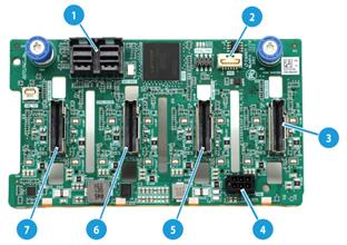
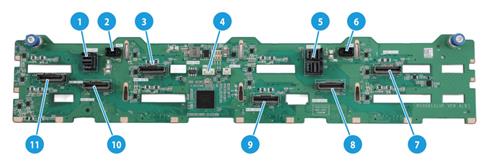
Front 12LFF UniBay drive backplane
The PCA-BP-12LFF-UniBay-2U-G5 12LFF UniBay drive backplane can be installed at the server front to support 12 3.5-inch drives.
Figure 28 12LFF UniBay drive backplane
|
(1) x4 Mini-SAS-HD connector (SAS PORT 2) (controls SAS/SATA drives in the last four slots attached to the backplane) |
|
|
(2) Power connector 2 (PWR2) |
(3) SlimSAS connector A3/A4 (PCIe4.0 x8) (NVMe-A3/A4) |
|
(4) AUX connector (AUX)Power connector 1 (PWR1) |
|
|
(5) x8 Mini-SAS-HD connector (SAS PORT 1) (controls SAS/SATA drives in the first eight slots attached to the backplane) |
|
|
(6) Power connector 1 (PWR1) |
|
|
(7) SlimSAS connector C1/C2 (PCIe4.0 x8)(NVMe-C1/C2) |
|
|
(8) SlimSAS connector C3/C4 (PCIe4.0 x8)(NVMe-C3/C4) |
|
|
(9) SlimSAS connector A1/A2 (PCIe4.0 x8)(NVMe-A1/A2) |
|
|
(10) SlimSAS connector B1/B2 (PCIe4.0 x8)(NVMe-B1/B2) |
|
|
(11) SlimSAS connector B3/B4 (PCIe4.0 x8)(NVMe-B3/B4) |
|
|
The description for PCIe4.0 x8 is as follows: · PCIe4.0: Fourth-generation signal speed. · x8: Bus bandwidth. |
|
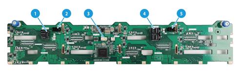
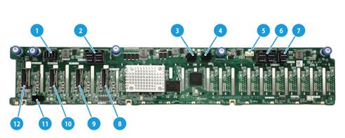
Front 25SFF UniBay drive backplane
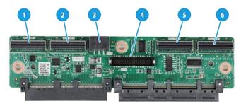
The PCA-BP-25SFF-2U-G5 25SFF UniBay drive backplane can be installed at the server front to support 25 2.5-inch drives, including 17 SAS/SATA drives and 8 SAS/SATA/NVMe drives. The backplane is embedded with an Expander chip, which allows it to manage 25 SAS/SATA drives through an x8 Mini-SAS-HD port.
The backplane also provides three downlink connectors to connect to other backplanes and manage more drives.
Figure 29 25SFF UniBay drive backplane
|
(1) x4 Mini-SAS-HD downlink connector 3 (SAS EXP 3) |
|
|
(2) x8 Mini-SAS-HD uplink connector (SAS PORT) (controls all drives attached to the backplane) |
(3) Power connector 2 (PWR2) |
|
(4) Power connector 1 (PWR1) |
(5) AUX connector (AUX) |
|
(6) x8 Mini-SAS-HD downlink connector 2 (SAS EXP 2) |
|
|
(7) x3 Mini-SAS-HD downlink connector 1 (SAS EXP 1) |
|
|
(8) SlimSAS connector A1/A2 (PCIe4.0 x8)(NVMe-A1/A2) (supports NVMe drives) (corresponds to drives numbered 17 and 18) |
|
|
(9) SlimSAS connector A3/A4 (PCIe4.0 x8)(NVMe-A3/A4) (supports NVMe drives) (corresponds to drives numbered 19 and 20) |
|
|
(10) SlimSAS connector B1/B2 (PCIe4.0 x8)(NVMe-B1/B2) (supports NVMe drives) (corresponds to drives numbered 21 and 22) |
|
|
(11) Power connector 3 (PWR3) |
|
|
(12) SlimSAS connector B3/B4 (PCIe4.0 x8)(NVMe-B3/B4) (supports NVMe drives) (corresponds to drives numbered 23 and 24) |
|
|
The description for PCIe4.0 x8 is as follows: · PCIe4.0: Fourth-generation signal speed. · x8: Bus bandwidth. For more information about drive numbering, see Figure 15. |
|
Front 25SFF drive backplane (17SAS/SATA+8UniBay)
The PCA-BP-25SFF-2U-G5-1 25SFF drive backplane can be installed at the server fron to support 25 2.5-inch drives, including 17 SAS/SATA drives and 8 SAS/SATA/NVMe drives. The backplane can use a x8 Mini-SAS-HD interface to manage 25 SAS/SATA drives. The 25SFF drive backplane is embedded with an Expander chip and provides a downlink interface to connect to other backplanes and manage more drives.
Figure 30 25SFF drive backplane
|
(1) x8 Mini-SAS-HD uplink interface (SAS PORT) (controls all drives attached to the backplane) |
|
|
(2) Power connector 2 (PWR2) |
(3) Power connector 1 (PWR1) |
|
(4) AUX connector (AUX) |
(5) x3 Mini-SAS-HD downlink connector (SAS EXP 1) |
|
(6) SlimSAS connector A1/A2 (PCIe4.0 x8) (supports NVMe drives) (corresponds to drives numbered 17 and 18) (NVMe-A1/A2) |
|
|
(7) SlimSAS connector A3/A4 (PCIe4.0 x8) (supports NVMe drives) (corresponds to drives numbered 19 and 20) (NVMe-A3/A4) |
|
|
(8) SlimSAS connector B1/B2 (PCIe4.0 x8) (supports NVMe drives) (corresponds to drives numbered 21 and 22) (NVMe-B1/B2) |
|
|
(9) Power connector 3 (PWR3) |
|
|
(10) SlimSAS connector B3/B4 (PCIe4.0 x8)(supports NVMe drives) (corresponds to drives numbered 23 and 24) (NVMe-B3/B4) |
|
|
The description for PCIe4.0 x8 is as follows: · PCIe4.0: Fourth-generation signal speed. · x8: Bus bandwidth. For more information about drive numbering, see Figure 15. |
|
Mid 4LFF SAS/SATA drive backplane
The PCA-BP-4LFF-2U-M-G5 4LFF SAS/SATA drive backplane can be installed at the middle of the server to support four 3.5-inch SAS/SATA drives.
Figure 31 Mid 4LFF SAS/SATA drive backplane
|
(1) AUX connector (AUX1) |
(2) Power connector (PWR 1) |
|
(3) x4 Mini-SAS-HD connector (SAS PORT1) |
|
Mid 4SFF UniBay drive backplane
The PCA-BP-4SFF-4UniBay-2U-G5 mid 4SFF UniBay drive backplane can be installed in the middle of the server front to support four 2.5-inch SAS/SATA/NVMe drives.
Figure 32 Mid 4SFF UniBay drive backplane
|
(1) SlimSAS connector 3/4 (PCIe4.0 x8)(NVMe-3/4) |
(2) AUX connector (AUX) |
|
(3) SlimSAS connector 1/2 (PCIe4.0 x8)(NVMe-1/2) |
(4) x4 Mini-SAS-HD connector (SAS PORT) |
|
(5) Power connector (PWR) |
|
|
The description for PCIe4.0 x8 is as follows: · PCIe4.0: Fourth-generation signal speed. · x8: Bus bandwidth. |
|
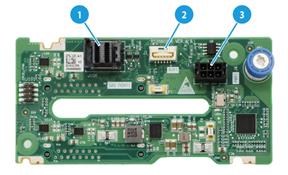
Rear 2LFF SAS/SATA drive backplane
The PCA-BP-2LFF-2U-G5 rear 2LFF SAS/SATA drive backplane can be installed at the server rear to support two 3.5-inch SAS/SATA drives.
Figure 33 Rear 2LFF SAS/SATA drive backplane
|
(1) x4 Mini-SAS-HD connector (SAS PORT 1) |
(2) AUX connector (AUX 1) |
|
(3) Power connector (PWR 1) |
|
Rear 4LFF SAS/SATA drive backplane
The PCA-BP-4LFF-2U-G5 rear 4LFF SAS/SATA drive backplane can be installed at the server rear to support four 3.5-inch SAS/SATA drives.
Figure 34 Rear 4LFF SAS/SATA drive backplane
|
(1) AUX connector (AUX) |
(2) Power connector (PWR) |
|
(3) x4 Mini-SAS-HD connector (SAS PORT) |
|
Rear 2SFF SAS/SATA drive backplane
The PCA-BP-2SFF-2U-G5 rear 2SFF SAS/SATA drive backplane can be installed at the server rear to support two 2.5-inch SAS/SATA drives.
Figure 35 Rear 2SFF SAS/SATA drive backplane
|
(1) Power connector (PWR) |
(2) x4 Mini-SAS-HD connector (SAS PORT) |
|
(3) AUX connector (AUX) |
|
Rear 2SFF UniBay drive backplane
The PCA-BP-2SFF-2UniBay-2U-G5 rear 2SFF UniBay drive backplane can be installed at the server rear to support two 2.5-inch SAS/SATA/NVMe drives.
Figure 36 Rear 2SFF UniBay drive backplane
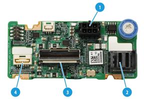
|
(1) Power connector (PWR) |
(2) x4 Mini-SAS-HD connector (SAS PORT) |
|
(3) SlimSAS connector (PCIe4.0 x8)(NVMe) |
(4) AUX connector (AUX) |
|
The description for PCIe4.0 x8 is as follows: · PCIe4.0: Fourth-generation signal speed. · x8: Bus bandwidth. |
|
Rear 4SFF SAS/SATA drive backplane
The PCA-BP-4SFF-2U-G5 rear 4SFF SAS/SATA drive backplane can be installed at the server rear to support four 2.5-inch SAS/SATA drives.
Figure 37 Rear 4SFF SAS/SATA drive backplane
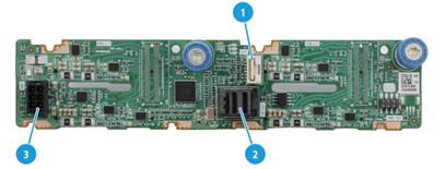
|
(1) AUX connector (AUX) |
(2) x4 Mini-SAS-HD connector (SAS PORT) |
|
(3) Power connector (PWR) |
|
Rear 4SFF UniBay drive backplane
The PCA-BP-4SFF-4UniBay-2U-G5 rear 4SFF UniBay drive backplane can be installed at the server rear to support four 2.5-inch SAS/SATA/NVMe drives.
Figure 38 Rear 4SFF UniBay drive backplane

|
(1) SlimSAS connector (PCIe4.0 x8) (NVMe-3/4) |
(2) AUX connector (AUX) |
|
(3) SlimSAS connector (PCIe4.0 x8) (NVMe-1/2) |
(4) x4 Mini-SAS-HD connector (SAS PORT) |
|
(5) Power connector (PWR) |
|
|
The description for PCIe4.0 x8 is as follows: · PCIe4.0: Fourth-generation signal speed. · x8: Bus bandwidth. |
|
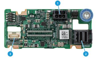
Rear 2SFF UniBay drive backplane (for OCP adapter)
The PCA-BP-2UniBay-OCP-2U-G5 rear 2SFF UniBay drive backplane can be installed together with an OCP adapter at the server rear to support two 2.5-inch SAS/SATA/NVMe drives.
Figure 39 2SFF UniBay drive backplane
|
(1) SlimSAS connector (PCIe4.0 x8) (NVME-A1/A2) |
(2) Power connector (PWR) |
|
(3) AUX connector (AUX) |
(4) x4 Mini-SAS-HD connector (SAS PORT) |
|
The description for PCIe4.0 x8 is as follows: · PCIe4.0: Fourth-generation signal speed. · x8: Bus bandwidth. |
|
Riser cards
To expand the server with PCIe modules, install riser cards on the PCIe riser connectors.
Riser card guidelines
Each PCIe slot in a riser card can supply a maximum of 75 W of power to the PCIe module. You must connect a separate power cord to the PCIe module if it requires more than 75 W of power.
PCIe slots 11 through 14 on the PCA-R4900-4GPU-G5 rear 4GPU module can supply 300 W of power except that you must connect it to an external power cable.
If a processor is faulty or absent, the PCIe slots connected to it are unavailable.
The slot number of a PCIe slot varies by the PCIe riser connector that holds the riser card. For example, slot 1/4 represents PCIe slot 1 if the riser card is installed on connector 1 and represents PCIe slot 4 if the riser card is installed on connector 2. For information about PCIe riser connector locations, see "Rear panel view."
RC-1FHFL-R3-2U-G5
|
Item |
Specifications |
|
PCIe riser connector |
Connector 3 |
|
PCIe slots |
Slot 7: PCIe4.0 ×16 (16, 8, 4, 2, 1) for processor 2 NOTE: The numbers in parentheses represent supported link widths. |
|
Form factors of PCIe modules |
FHFL |
|
Maximum power supplied per PCIe slot |
75 W |
Figure 40 RC-1FHFL-R3-2U-G5 riser card
|
(1) GPU module power connector |
(2) PCIe4.0 x16 slot 7 |
RC-2FHFL-R3-2U-G5
|
Item |
Specifications |
|
PCIe riser connector |
Connector 3 |
|
PCIe slots |
Slot 7: PCIe4.0 ×16 (8, 4, 2, 1) for processor 2 Slot 8: PCIe4.0 ×16 (8, 4, 2, 1) for processor 2 NOTE: The numbers in parentheses represent supported link widths. You can only install x8 PCIe modules in the slots. |
|
Form factors of PCIe modules |
FHFL |
|
Maximum power supplied per PCIe slot |
75 W |
Figure 41 RC-2FHFL-R3-2U-G5 riser card
|
(1) GPU module power connector |
(2) PCIe4.0 x8 slot 8 |
|
(3) PCIe4.0 x8 slot 7 |
|
RC-2HHHL-R3-2U-G5
|
Item |
Specifications |
|
PCIe riser connector |
Connector 3 |
|
PCIe slots |
Slot 7: PCIe4.0 ×16 (8, 4, 2, 1) for processor 2 Slot 8: PCIe4.0 ×16 (8, 4, 2, 1) for processor 2 NOTE: The numbers in parentheses represent supported link widths. You can only install x8 PCIe modules in the slots. |
|
Form factors of PCIe modules |
HHHL |
|
Maximum power supplied per PCIe slot |
75 W |
Figure 42 RC-2HHHL-R3-2U-G5 riser card
|
(1) PCIe4.0 x8 slot 7 |
(2) PCIe4.0 x8 slot 7 |
RC-2HHHL-R4-2U-G5
|
Item |
Specifications |
|
PCIe riser connector |
Connector 4 |
|
PCIe slots |
Mid GPU adapter not present: · Slot 9: PCIe4.0 ×16 (8, 4, 2, 1) for processor 2 · Slot 10: PCIe4.0 ×16 (8, 4, 2, 1) for processor 2 Mid GPU adapter present: · Slot 9: PCIe4.0 ×16 (8, 4, 2, 1) for processor 1 Slot 10: PCIe4.0 ×16 (8, 4, 2, 1) for processor 2 NOTE: The numbers in parentheses represent supported link widths. You can only install x8 PCIe modules in the slots. |
|
SlimSAS connectors |
Mid GPU adapter not present: · SlimSAS port 1 (x8 SlimSAS port, connected to LP SlimSAS connector B1/B2 on the system board) for processor 2, providing an x8 PCIe link for slot 9 · SlimSAS port 2 (x8 SlimSAS port, connected to LP SlimSAS connector B3/B4 on the system board) for processor 2, providing an x8 PCIe link for slot 10 Mid GPU adapter not present: · SlimSAS port 1 (x8 SlimSAS port, connected to the SlimSAS port on Riser 1 for processor 1, providing an x8 PCIe link for slot 9 · SlimSAS port 2 (x8 SlimSAS port, connected to the SlimSAS connector on Riser 2) for processor 2, providing an x8 PCIe link for slot 10 |
|
Form factors of PCIe modules |
HHHL |
|
Maximum power supplied per PCIe slot |
75 W |
Figure 43 RC-2HHHL-R4-2U-G5 riser card

|
(1) GPU module power connector |
(2) PCIe4.0 x8 slot 10 |
|
(3) PCIe4.0 x8 slot 9 |
(4) SlimSAS connector 1 |
|
(5) SlimSAS connector 2 |
(6) AUX connector |
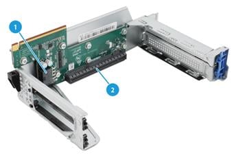
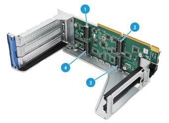
RC-3FHFL-2U-G5
|
Item |
Specifications |
|
PCIe riser connector |
Connector 1 or 2 |
|
PCIe slots |
Connector 1: · Slot 1: PCIe4.0 ×16 (8, 4, 2, 1) for processor 1 · Slot 2: PCIe4.0 ×16 (16, 8, 4, 2, 1) for processor 1 · Slot 3: PCIe4.0 ×16 (8, 4, 2, 1) for processor 1 Connector 2: · Slot 4: PCIe4.0 ×16 (8, 4, 2, 1) for processor 2 · Slot 5: PCIe4.0 ×16 (16, 8, 4, 2, 1) for processor 2 · Slot 6: PCIe4.0 ×16 (8, 4, 2, 1) for processor 2 NOTE: The numbers in parentheses represent supported link widths. You can only install x8 PCIe modules in slots 1, 3, 4, and 6, which are PCIe4.0 ×16 (8, 4, 2, 1) slots. |
|
Form factors of PCIe modules |
FHFL |
|
Maximum power supplied per PCIe slot |
75 W |
Figure 44 RC-3FHFL-2U-G5 riser card
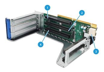
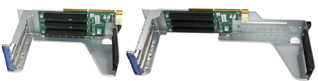
Figure 45 Adjustable extension of the RC-3FHFL-2U-G5 riser card
|
(1) PCIe4.0 x8 slot 3/6 |
(2) PCIe4.0 x16 slot 2/5 |
|
(3) GPU module power connector |
(4) PCIe4.0 x8 slot 1/4 |
|
For various PCIe card sizes, the riser card bracket supports adjustable extension. See Figure 45 for a comparison. |
|
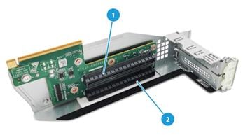
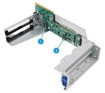
RC-3FHFL-2U-MH-G5
|
Item |
Specifications |
|
PCIe riser connector |
Connector 1 or 2 |
|
PCIe slots |
PCIe riser connector 1: · Slot 1/2/3: PCIe4.0 ×16 (8, 4, 2, 1) for processor 1 PCIe riser connector 2: · Slot 4/5/6: PCIe4.0 ×16 (8, 4, 2, 1) for processor 2 NOTE: The numbers in parentheses represent supported link widths. You can only install x8 PCIe modules in the slots. |
|
SlimSAS connectors |
PCIe riser connector 1: · x8 SlimSAS port that provides an x8 PCIe link to processor 1 PCIe riser connector 2: · x8 SlimSAS port that provides an x8 PCIe link to processor 2 |
|
Form factors of PCIe modules |
FHFL |
|
Maximum power supplied per PCIe slot |
75 W |
Figure 46 RC-3FHFL-2U-MH-G5 riser card
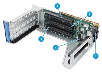
|
(1) PCIe4.0 x8 slot 3/6 |
(2) PCIe4.0 x8 slot 2/5 |
|
(3) GPU module power connector |
(4) SlimSAS connector |
|
(5) PCIe4.0 x8 slot 1/4 |
|
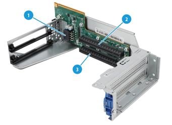
RC-3FHFL-2U-SW-G5
|
Item |
Specifications |
|
PCIe riser connector |
Connector 1 or 2 |
|
PCIe slots |
PCIe riser connector 1: · Slot 1/2/3: PCIe4.0 ×16 (16, 8, 4, 2, 1) for processor 1 PCIe riser connector 2: · Slot 4/5/6: PCIe4.0 ×16 (16, 8, 4, 2, 1) for processor 2 NOTE: The numbers in parentheses represent supported link widths. |
|
SlimSAS connectors |
· PCIe riser connector 1: ¡ SlimSAS port 1 (x8 SlimSAS port, connected to LP SlimSAS connector A1/A2 on the system board) for processor 1, providing a x16 PCIe link for slot 1 together with SlimSAS port 2. ¡ SlimSAS port 2 (x8 SlimSAS port, connected to LP SlimSAS connector A3/A4 on the system board) for processor 1, providing a x16 PCIe link for slot 1 together with SlimSAS port 1. · PCIe riser connector 2: ¡ SlimSAS port 1 (x8 SlimSAS port, connected to LP SlimSAS connector B1/B2 on the system board) for processor 2, providing x16 PCIe link for slot 4 together with SlimSAS port 2. ¡ SlimSAS port 2 (x8 SlimSAS port, connected to LP SlimSAS connector B3/B4 on the system board) for processor 2, providing x16 PCIe link for slot 4 together with SlimSAS port 1. |
|
Form factors of PCIe modules |
FHFL |
|
Maximum power supplied per PCIe slot |
75 W |
Figure 47 RC-3FHFL-2U-SW-G5 riser card
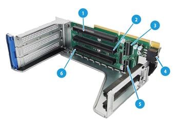
|
(1) PCIe4.0 x16 slot 3/6 |
(2) PCIe4.0 x16 slot 2/5 |
|
(3) SlimSAS connector 2 |
(4) GPU module power connector |
|
(5) SlimSAS connector 1 |
(6) PCIe4.0 x16 slot 1/4 |
RC-5HHHL-R5-2U-G5 (mid GPU adapter)
|
Item |
Specifications |
|
PCIe riser connector |
N/A. The adapter is attached to the pegs in the inner sides of the chassis. |
|
PCIe slots |
· Slot 12: PCIe4.0 ×16 (8, 4, 2, 1) for processor 1 · Slot 13: PCIe4.0 ×16 (8, 4, 2, 1) for processor 1 · Slot 14: PCIe4.0 ×16 (8, 4, 2, 1) for processor 2 · Slot 15: PCIe4.0 ×16 (8, 4, 2, 1) for processor 2 NOTE: The numbers in parentheses represent supported link widths. You can only install x8 PCIe modules in the slots. |
|
SlimSAS connectors |
· SlimSAS port 2 (x8 SlimSAS port, connected to LP SlimSAS connector A1/A2 on the system board) for processor 1, providing an x8 PCIe link for slot 12 · SlimSAS port 3 (x8 SlimSAS port, connected to LP SlimSAS connector A3/A4 on the system board) for processor 1, providing an x8 PCIe link for slot 13 · SlimSAS port 4 (x8 SlimSAS port, connected to the SlimSAS connector B1/B2 on the system board) for processor 2, providing an x8 PCIe link for slot 14 · SlimSAS port 5 (x8 SlimSAS port, connected to the SlimSAS connector B3/B4 on the system board) for processor 2, providing an x8 PCIe link for slot 15 |
|
Form factors of PCIe modules |
HHHL |
|
Maximum power supplied per PCIe slot |
75 W |
Figure 48 RC-5HHHL-R5-2U-G5 mid GPU adapter
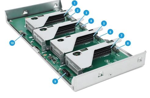
|
(1) PCIe4.0 x8 slot 12 |
(2) SlimSAS connector 2 |
|
(3) PCIe4.0 x8 slot 13 |
(4) SlimSAS connector 3 |
|
(5) PCIe4.0 x8 slot 14 |
(6) SlimSAS connector 4 |
|
(7) PCIe4.0 x8 slot 15 |
(8) SlimSAS connector 5 |
|
(9) Power connector |
(10) AUX connector |
RC-8NVMe-2U-G5
|
Item |
Specifications |
|
PCIe riser connector |
Connector 1 or 2 |
|
SlimSAS connectors |
PCIe riser connector 1: · LP SlimSAS connector A1/A2) for processor 1, providing an x8 PCIe link · LP SlimSAS connector B1/B2) for processor 1, providing an x8 PCIe link · LP SlimSAS connector B3/B4) for processor 1, providing an x8 PCIe link · LP SlimSAS connector A3/A4) for processor 1, providing an x8 PCIe link PCIe riser connector 2: · LP SlimSAS connector A1/A2) for processor 2, providing an x8 PCIe link · LP SlimSAS connector B1/B2) for processor 2, providing an x8 PCIe link · LP SlimSAS connector B3/B4) for processor 2, providing an x8 PCIe link · LP SlimSAS connector A3/A4) for processor 2, providing an x8 PCIe link |
|
Form factors of PCIe modules |
N/A |
|
Maximum power supplied per PCIe slot |
N/A |
Figure 49 RC-8NVMe-2U-G5 riser card
|
(1) LP SlimSAS connector A1/A2 (PCIe4.0 x8) |
(2) LP SlimSAS connector B1/B2 (PCIe4.0 x8) |
|
(3) LP SlimSAS connector B3/B4 (PCIe4.0 x8) |
(4) LP SlimSAS connector A3/A4 (PCIe4.0 x8) |
RC-4NVMe-R3-2U-G5
|
Item |
Specifications |
|
PCIe riser connector |
Connector 3 |
|
SlimSAS connectors |
· LP SlimSAS connector A1/A2) for processor 2, providing an x8 PCIe link · LP SlimSAS connector A3/A4) for processor 2, providing an x8 PCIe link |
|
Form factors of PCIe modules |
N/A |
|
Maximum power supplied per PCIe slot |
N/A |
Figure 50 RC-4NVMe-R3-2U-G5 riser card
|
(1) LP SlimSAS connector A1/A2 (PCIe4.0 x8) |
(2) LP SlimSAS connector A3/A4 (PCIe4.0 x8) |
|
The description for PCIe4.0 x8 is as follows: · PCIe4.0: Fourth-generation signal speed. · x8: Bus bandwidth. |
|
PCA-R4900-4GPU-G5
Figure 51 PCA-R4900-4GPU-G5 (1)
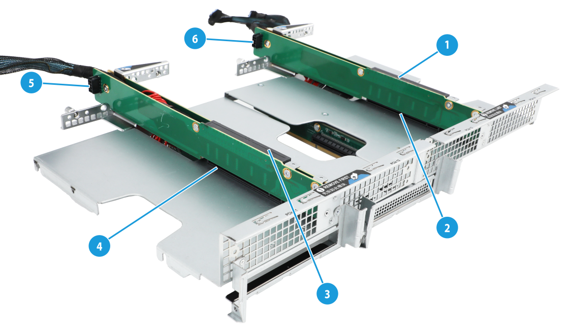
Figure 52 PCA-R4900-4GPU-G5 (2)
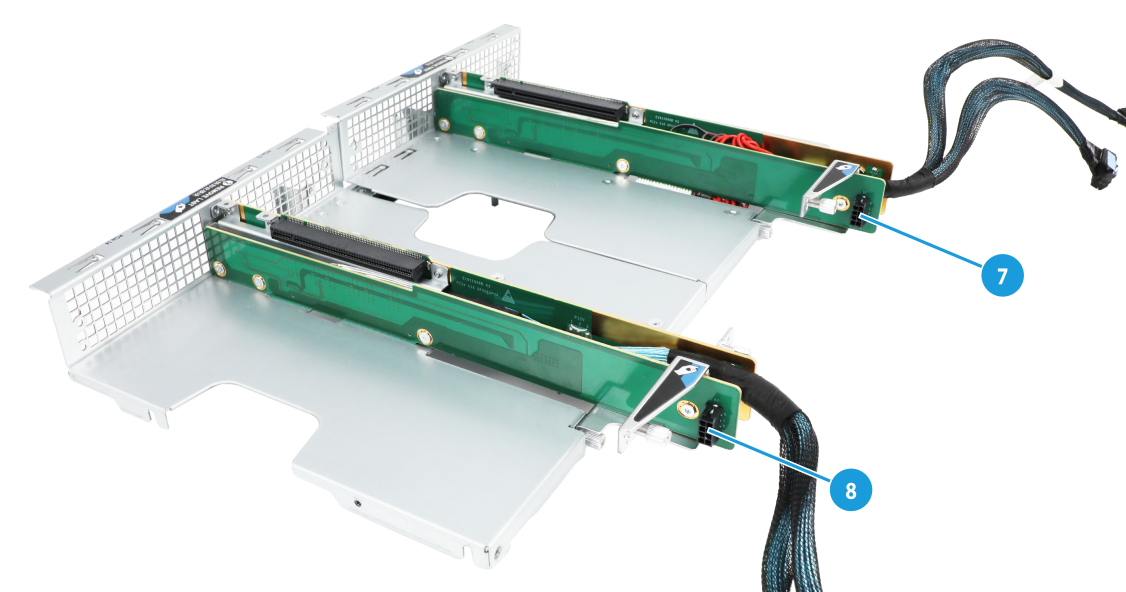
Figure 53 PCA-R4900-4GPU-G5 (3)
|
(1) PCIe4.0 x16 slot 14 |
(2) PCIe4.0 x16 slot 13 |
|
(3) PCIe4.0 x16 slot 12 |
(4) PCIe4.0 x16 slot 11 |
|
(5 to 8) GPU power connector |
(9) PCIe4.0 x16 slot 6 |
|
(10) PCIe4.0 x16 slot 3 |
|
OCP adapter
Figure 54 OCP adapter
|
(1) SlimSAS connector 4 |
(2) SlimSAS connector 3 |
|
(3) Power connector |
(4) AUX connector |
|
(5) SlimSAS connector 2 |
(6) SlimSAS connector 1 |
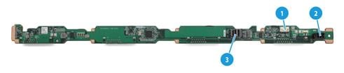
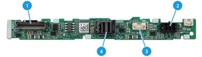
LCD smart management module
An LCD smart management module displays basic server information, operating status, and fault information, and provides diagnostics and troubleshooting capabilities. You can locate and troubleshoot component failures by using the LCD module in conjunction with the event logs generated in HDM.
Figure 55 LCD smart management module
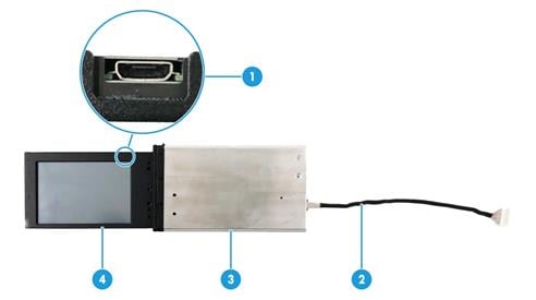
Table 17 LCD smart management module description
|
No. |
Item |
Description |
|
1 |
Mini-USB connector |
Used for upgrading the firmware of the LCD module. |
|
2 |
LCD module cable |
Connects the LCD module to the system board of the server. For information about the LCD smart management module connector on the system board, see "System board." |
|
3 |
LCD module shell |
Protects and secures the LCD screen. |
|
4 |
LCD screen |
Displays basic server information, operating status, and fault information. |
Fan modules
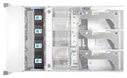
The server supports six hot swappable fan modules. The server supports N+1 fan module redundancy. Figure 56 shows the layout of the fan modules in the chassis.
The server can adjust the fan rotation speed based on the server temperature to provide optimal performance with balanced ventilation and noise.
During system POST and operation, the server will be gracefully powered off through HDM if the temperature detected by any sensor in the server reaches the critical threshold. The server will be powered off directly if the temperature of any key components such as processors exceeds the upper threshold. For more information about the thresholds and detected temperatures, access the HDM Web interface and see HDM online help.
PCIe slot numbering
The server supports installing mid GPU adapters in the middle and installing riser cards, GPU modules, and OCP 3.0 adapter modules at the rear. The PCIe slot number depends on your configuration.
Figure 57 PCIe slot numbering when riser cards are installed at the rear

Figure 58 PCIe slot numbering when UniBay drive backplanes and OCP 3.0 adapter modules are installed
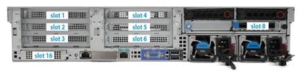
Figure 59 PCIe slot numbering when GPU modules are installed at the rear
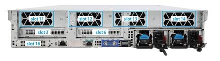
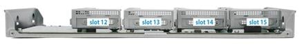
Figure 60 PCIe slot numbering on a mid GPU adapter
|
|
NOTE: You cannot install GPU modules both in the middle and at the rear of the server. |
PCIe modules
Typically, the PCIe modules are available in the following standard form factors:
· LP—Low profile.
· FHHL—Full height and half length.
· FHFL—Full height and full length.
· HHHL—Half height and half length.
· HHFL—Half height and full length.
Restrictions and guidelines
· If a processor is faulty or absent, the PCIe slots connected to it are unavailable. For more information about riser connectors on the system board, see "System board components." For more information about PCIe slots on riser cards, see "Riser cards."
· Use a SlimSAS cable to connect the SlimSAS connector to the LP SlimSAS connector on the system board to provide link width for the corresponding PCIe slot on the riser card.
· You can install a PCIe module in a PCIe slot for a larger-sized PCIe module. For example, an LP PCIe module can be installed in a slot for an FHFL PCIe module.
· A PCIe slot can supply power to the installed PCIe module if the maximum power consumption of the module does not exceed 75 W. If the maximum power consumption exceeds 75 W, a power cord is required.
· The description for PCIe4.0 x8 is as follows:
¡ PCIe4.0: Fourth-generation signal speed.
¡ X8: Compatible bus bandwidth, including x8, x4, x2, and x1.
· x8 in x8 SlimSAS represents the bus bandwidth.
· By default, the connector width is x16 for standard PCIe module slots.
Riser card and PCIe module compatibility
Figure 61 Riser card and PCIe module compatibility (1)
|
Riser card model |
Riser card location |
PCIe slots and cable connector on a riser card |
PCIe slot or connector description |
PCIe module for PCIe slot or connector |
PCIe slot power capability |
Processor |
|
|
RC-3FHFL-2U-G5 |
PCIe riser connector 1 |
PCIe slots |
Slot 1 |
PCIe4.0 x8 |
FHFL |
75W |
Processor 1 |
|
Slot 2 |
PCIe4.0 x16 |
FHFL |
75W |
Processor 1 |
|||
|
Slot 3 |
PCIe4.0 x8 |
FHFL |
75W |
Processor 1 |
|||
|
PCIe riser connector2 |
Slot 4 |
PCIe4.0 x8 |
FHFL |
75W |
Processor 2 |
||
|
Slot 5 |
PCIe4.0 x16 |
FHFL |
75W |
Processor 2 |
|||
|
Slot 6 |
PCIe4.0 x8 |
FHFL |
75W |
Processor 2 |
|||
|
RC-3FHFL-2U-MH-G5 |
PCIe riser connector 1 |
PCIe slots |
Slots 1 to 3 |
PCIe4.0 x8 |
FHFL |
75W |
Processor 1 |
|
Cable connector |
SlimSAS connector |
x8 SlimSAS connector |
Provides an x8 PCIe link |
- |
Processor 1 |
||
|
PCIe riser connector2 |
PCIe slots |
Slots 4 to 6 |
PCIe4.0 x8 |
FHFL |
75W |
Processor 2 |
|
|
Cable connector |
SlimSAS connector |
x8 SlimSAS connector |
Provides an x8 PCIe link |
- |
Processor 2 |
||
Figure 62 Riser card and PCIe module compatibility (2)
|
Riser card model |
Riser card location |
PCIe slots and cable connector on a riser card |
PCIe slot or connector description |
PCIe module for PCIe slot or connector |
PCIe slot power capability |
Processor |
|
|
RC-3FHFL-2U-SW-G5 |
PCIe riser connector 1 |
PCIe slots |
Slots 1 to 3 |
PCIe4.0 x16 |
FHFL |
75 W |
Processor 1 |
|
Cable connector |
SlimSAS connector 1 |
x8 SlimSAS connector |
Connected to LP SlimSAS connector A1/A2 on the system board to provide a x16 PCIe link to slot 1 together with another x8 SlimSAS connector |
- |
Processor 1 |
||
|
SlimSAS connector 2 |
x8 SlimSAS connector |
Connected to LP SlimSAS connector A3/A4 on the system board to provide a x16 PCIe link to slot 1 together with another x8 SlimSAS connector |
- |
Processor 1 |
|||
|
PCIe riser connector 2 |
PCIe slots |
Slots 4 to 6 |
PCIe4.0 x16 |
FHHL |
75W |
Processor 2 |
|
|
Cable connector |
SlimSAS connector 1 |
x8 SlimSAS connector |
Connected to LP SlimSAS connector B1/B2 on the system board to provide a x16 PCIe link to slot 4 together with another x8 SlimSAS connector |
- |
Processor 2 |
||
|
SlimSAS connector 2 |
x8 SlimSAS connector |
Connected to LP SlimSAS connector B3/B4 on the system board to provide a x16 PCIe link to slot 4 together with another x8 SlimSAS connector |
- |
Processor 2 |
|||
Figure 63 Riser card and PCIe module compatibility (3)
|
Riser card model |
Riser card location |
PCIe slots and cable connector on a riser card |
PCIe slot or connector description |
PCIe module for PCIe slot or connector |
PCIe slot power capability |
Processor |
|
|
RC-8NVMe-2U-G5 |
PCIe riser connector 1 |
Cable connector |
LP SlimSAS connector A1/A2 |
x8 SlimSAS connector |
Provides an x8 PCIe link |
- |
Processor 1 |
|
LP SlimSAS connector B1/B2 |
x8 SlimSAS connector |
Provides an x8 PCIe link |
- |
Processor 1 |
|||
|
LP SlimSAS connector B3/B4 |
x8 SlimSAS connector |
Provides an x8 PCIe link |
- |
Processor 1 |
|||
|
LP SlimSAS connector A3/A4 |
x8 SlimSAS connector |
Provides an x8 PCIe link |
- |
Processor 1 |
|||
|
PCIe riser connector 2 |
Cable connector |
LP SlimSAS connector A1/A2 |
x8 SlimSAS connector |
Provides an x8 PCIe link |
- |
Processor 2 |
|
|
LP SlimSAS connector B1/B2 |
x8 SlimSAS connector |
Provides an x8 PCIe link |
- |
Processor 2 |
|||
|
LP SlimSAS connector B3/B4 |
x8 SlimSAS connector |
Provides an x8 PCIe link |
- |
Processor 2 |
|||
|
LP SlimSAS connector A3/A4 |
x8 SlimSAS connector |
Provides an x8 PCIe link |
- |
Processor 2 |
|||
|
RC-1FHFL-R3-2U-G5 |
PCIe riser connector 3 |
PCIe slots |
Slot 7 |
PCIe4.0 x16 |
FHFL |
75W |
Processor 2 |
|
RC-2FHFL-R3-2U-G5 |
PCIe riser connector 3 |
PCIe slots |
Slot 7 |
PCIe4.0 x8 |
FHFL |
75W |
Processor 2 |
|
Slot 8 |
PCIe4.0 x8 |
FHFL |
75W |
Processor 2 |
|||
Figure 64 Riser card and PCIe module compatibility (4)
|
Riser card model |
Riser card location |
PCIe slots and cable connector on a riser card |
PCIe slot or connector description |
PCIe module for PCIe slot or connector |
PCIe slot power capability |
Processor |
|
|
RC-2HHHL-R3-2U-G5 |
PCIe riser connector 3 |
PCIe slots |
Slot 7 |
PCIe4.0 x8 |
HHHL |
75W |
Processor 2 |
|
Slot 8 |
PCIe4.0 x8 |
HHHL |
75W |
Processor 2 |
|||
|
RC-4NVMe-R3-2U-G5 |
PCIe riser connector 3 |
Cable connector |
LP SlimSAS connector A1/A2 |
x8 SlimSAS connector |
Provides an x8 PCIe link |
- |
Processor 2 |
|
LP SlimSAS connector A3/A4 |
x8 SlimSAS connector |
Provides an x8 PCIe link |
- |
Processor 2 |
|||
|
RC-2HHHL-R4-2U-G5 |
PCIe riser connector 4 (mid GPU module absent) |
PCIe slots |
Slot 9 |
PCIe4.0 x8 |
HHHL |
75W |
Processor 2 |
|
Slot 10 |
PCIe4.0 x8 |
HHHL |
75W |
Processor 2 |
|||
|
Cable connector |
SlimSAS connector 1 |
x8 SlimSAS connector |
Connected to the LP SlimSAS connector B1/B2 on the system board to provide an x8 PCIe link for slot 9 |
- |
Processor 2 |
||
|
SlimSAS connector 2 |
x8 SlimSAS connector |
Connected to the LP SlimSAS connector B3/B4 on the system board to provide an x8 PCIe link for slot 10 |
- |
Processor 2 |
|||
|
PCIe riser connector 4 (mid GPU module present) |
PCIe slots |
Slot 9 |
PCIe4.0 x8 |
HHHL |
75W |
Processor 1 |
|
|
Slot 10 |
PCIe4.0 x8 |
HHHL |
75W |
Processor 2 |
|||
|
Cable connector |
SlimSAS connector 1 |
x8 SlimSAS connector |
Connected to the SlimSAS connector of Riser1 to provide an x8 PCIe link for slot 9 |
- |
Processor 1 |
||
|
SlimSAS connector 2 |
x8 SlimSAS connector |
Connected to the SlimSAS connector of Riser2 to provide an x8 PCIe link for slot 10 |
- |
Processor 2 |
|||
Figure 65 Riser card and PCIe module compatibility (5)
|
Riser card model |
Riser card location |
PCIe slots and cable connector on a riser card |
PCIe slot or connector description |
PCIe module for PCIe slot or connector |
PCIe slot power capability |
Processor |
|
|
RC-2HHHL-R3-2U-G5 |
PCIe riser connector 3 |
PCIe slots |
Slot 7 |
PCIe4.0 x8 |
HHHL |
75W |
Processor 2 |
|
Slot 8 |
PCIe4.0 x8 |
HHHL |
75W |
Processor 2 |
|||
|
RC-4NVMe-R3-2U-G5 |
PCIe riser connector 3 |
Cable connector |
LP SlimSAS connector A1/A2 |
x8 SlimSAS connector |
Provides an x8 PCIe link |
- |
Processor 2 |
|
LP SlimSAS connector A3/A4 |
x8 SlimSAS connector |
Provides an x8 PCIe link |
- |
Processor 2 |
|||
|
RC-2HHHL-R4-2U-G5 |
PCIe Rriser connector 4 (mid GPU module absent) |
PCIe slots |
Slot 9 |
PCIe4.0 x8 |
HHHL |
75W |
Processor 2 |
|
Slot 10 |
PCIe4.0 x8 |
HHHL |
75W |
Processor 2 |
|||
|
Cable connector |
SlimSAS connector 1 |
x8 SlimSAS connector |
Connected to the LP SlimSAS connector B1/B2 on the system board to provide an x8 PCIe link for slot 9 |
- |
Processor 2 |
||
|
SlimSAS connector 2 |
x8 SlimSAS connector |
Connected to the LP SlimSAS connector B3/B4 on the system board to provide an x8 PCIe link for slot 10 |
- |
Processor 2 |
|||
|
PCIe riser connector 4 (mid GPU module present) |
PCIe slots |
Slot 9 |
PCIe4.0 x8 |
HHHL |
75W |
Processor 1 |
|
|
Slot 10 |
PCIe4.0 x8 |
HHHL |
75W |
Processor 2 |
|||
|
Cable connector |
SlimSAS connector 1 |
x8 SlimSAS connector |
Connected to the SlimSAS connector of Riser1 to provide an x8 PCIe link for slot 9 |
- |
Processor 1 |
||
|
SlimSAS connector 2 |
x8 SlimSAS connector |
Connected to the SlimSAS connector of Riser2 to provide an x8 PCIe link for slot 10 |
- |
Processor 2 |
|||
Figure 66 Riser card and PCIe module compatibility (6)
|
Riser card model |
Riser card location |
PCIe slots and cable connector on a riser card |
PCIe slot or connector description |
PCIe module for PCIe slot or connector |
PCIe slot power capability |
Processor |
|
|
RC-5HHHL-R5-2U-G5 |
Middle in the server (secured by the pegs at both sides in the chassis) |
PCIe slots |
Slot 12 |
PCIe4.0 x8 |
HHHL |
75W |
Processor 1 |
|
Slot 13 |
PCIe4.0 x8 |
HHHL |
75W |
Processor 1 |
|||
|
Slot 14 |
PCIe4.0 x8 |
HHHL |
75W |
Processor 2 |
|||
|
Slot 15 |
PCIe4.0 x8 |
HHHL |
75W |
Processor 2 |
|||
|
Cable connector |
SlimSAS connector 2 |
x8 SlimSAS connector |
Connected to the LP SlimSAS connector A1/A2 on the system board to provide an x8 PCIe link for slot 12 |
- |
Processor 1 |
||
|
SlimSAS connector 3 |
x8 SlimSAS connector |
Connected to the LP SlimSAS connector A3/A4 on the system board to provide an x8 PCIe link for slot 13 |
- |
Processor 1 |
|||
|
SlimSAS connector 4 |
x8 SlimSAS connector |
Connected to the LP SlimSAS connector B1/B2 on the system board to provide an x8 PCIe link for slot 14 |
- |
Processor 2 |
|||
|
SlimSAS connector 5 |
x8 SlimSAS connector |
Connected to the LP SlimSAS connector B3/B4 on the system board to provide an x8 PCIe link for slot 15 |
- |
Processor 2 |
|||
|
PCA-R4900-4GPU-G5 |
PCIe riser connector 1 & PCIe riser connector 2 |
PCIe slots |
Slot 3 |
PCIe4.0 x16 |
FHFL |
75W |
Processor 1 |
|
Slot 6 |
PCIe4.0 x16 |
FHFL |
75W |
Processor 2 |
|||
|
Slot 11 |
PCIe4.0 x16 |
FHFL |
300W* |
Processor 1 |
|||
|
Slot 12 |
PCIe4.0 x16 |
FHFL |
300W* |
Processor 1 |
|||
|
Slot 13 |
PCIe4.0 x16 |
FHFL |
300W* |
Processor 2 |
|||
|
Slot 14 |
PCIe4.0 x16 |
FHFL |
300W* |
Processor 2 |
|||
|
· 300W*: Slots 11 through 14 provided by the rear 4GPU module supports GPUs. If the total required power exceeds 300 W, an external GPU power cord is required. |
|||||||
Storage controllers
The server supports the following types of storage controllers:
· Embedded VROC controller—Embedded in the server and does not require installation.
· Standard storage controller—Comes in a standard PCIe form factor and typically requires a riser card for installation.
For some storage controllers, you can order a power fail safeguard module to prevent data loss from power outages. This module provides a flash card and a supercapacitor. When a system power failure occurs, the supercapacitor provides power for a minimum of 20 seconds. During this interval, the storage controller can transfer data from DDR memory to the flash card, where the data remains indefinitely or until the controller retrieves the data. If the storage controller contains a built-in flash card, you can order only a supercapacitor.
Embedded VROC controller
|
Item |
Specifications |
|
Type |
Embedded in PCH of the system board |
|
Number of internal ports |
12 internal SAS ports (compatible with SATA) |
|
Connectors |
· One onboard ×8 SlimSAS connector · Four onboard ×4 SlimSAS connectors |
|
Drive interface |
6 Gbps SATA 3.0 Supports drive hot swapping |
|
PCIe interface |
PCIe3.0 ×4 |
|
RAID levels |
0, 1, 5, 10 |
|
Built-in cache memory |
N/A |
|
Built-in flash |
N/A |
|
Power fail safeguard module |
Not supported |
|
Firmware upgrade |
Upgrade with the BIOS |
Standard storage controllers
For more information, visit the query tool at http://www.h3c.com/cn/Service/Document_Software/Document_Center/Server/.
NVMe VROC modules
|
Model |
RAID levels |
Compatible NVMe SSDs |
|
NVMe-VROC-Key-S |
0, 1, 10 |
All NVMe drives |
|
NVMe-VROC-Key-P |
0, 1, 5, 10 |
All NVMe drives |
|
NVMe-VROC-Key-I |
0, 1, 5, 10 |
Intel NVMe drives |
B/D/F information
Viewing B/D/F information
Table 18 lists the default Bus/Device/Function numbers (B/D/F) used by the server when the following conditions are all met:
· All processor sockets are installed with processors.
· All PCIe riser connectors are installed with riser cards.
· All PCIe slots in riser cards are installed with PCIe modules.
· An OCP network adapter is installed in slot 19.
B/D/F information in Table 18 might change if any of the above conditions is not met or a PCIe module with a PCIe bridge is installed.
For more information about riser cards, see "Riser cards." For more information the location of slot 19, see "Rear panel view."
For information about how to obtain B/D/F information, see "Obtaining B/D/F information."
Table 18 PCIe modules and the corresponding Bus/Device/Function numbers
|
Riser card model |
PCIe riser connector |
PCIe slot |
Processor |
Port number |
Root port (B/D/F) |
End point (B/D/F) |
|
RC-3FHHL-2U-SW-G5 |
PCIe riser connector 1 |
slot 2 |
Processor 1 |
Port 1A |
15:00.0 |
16:00.0 |
|
slot 4 |
CPU 3 |
Port 1A |
23:00.0 |
24:00.0 |
||
|
slot 6 |
Processor 1 |
Port 3A |
32:00.0 |
33:00.0 |
||
|
PCIe riser connector 2 |
slot 8 |
Processor 2 |
Port 2A |
57:00.0 |
58:00.0 |
|
|
slot 10 |
Processor 2 |
Port 1A |
43:00.0 |
44:00.0 |
||
|
slot 12 |
Processor 2 |
Port 3A |
6c:00.0 |
6d:00.0 |
||
|
RC-6FHHL-2U-SW-G5 |
PCIe riser connector 1 |
slot 1 |
Processor 1 |
Port 1C |
15:02.0 |
17:00.0 |
|
slot 2 |
Processor 1 |
Port 1A |
15:00.0 |
16:00.0 |
||
|
slot 3 |
CPU 3 |
Port 1C |
23:02.0 |
25:00.0 |
||
|
slot 4 |
CPU 3 |
Port 1A |
23:00.0 |
24:00.0 |
||
|
slot 5 |
Processor 1 |
Port 3A |
32:00.0 |
33:00.0 |
||
|
slot 6 |
Processor 1 |
Port 3C |
32.02.0 |
34:00.0 |
||
|
PCIe riser connector 2 |
slot 7 |
Processor 2 |
Port 2C |
57:02.0 |
59:00.0 |
|
|
slot 8 |
Processor 2 |
Port 2A |
57:00.0 |
58:00.0 |
||
|
slot 9 |
Processor 2 |
Port 1C |
43:02.0 |
45:00.0 |
||
|
slot 10 |
Processor 2 |
Port 1A |
43:00.0 |
44:00.0 |
||
|
slot 11 |
Processor 2 |
Port 3A |
6c:00.0 |
6d:00.0 |
||
|
slot 12 |
Processor 2 |
Port 3C |
6c:02.0 |
6e:00.0 |
||
|
RC-3FHHL-2U-SW-G5-1 |
PCIe riser connector 3 |
slot 14 |
CPU 4 |
Port 1A |
c3:00.0 |
c4:00.0 |
|
slot 15 |
CPU 4 |
Port 3A |
ec:00.0 |
ed:00.0 |
||
|
slot 16 |
CPU 4 |
Port 2A |
d7:00.0 |
d8:00.0 |
||
|
RC-6FHHL-2U-SW-G5-1 |
PCIe riser connector 3 |
slot 13 |
CPU 4 |
Port 1C |
c3:02.0 |
c5:00.0 |
|
slot 14 |
CPU 4 |
Port 1A |
c3:00.0 |
c4:00.0 |
||
|
slot 15 |
CPU 4 |
Port 2A |
d7:00.0 |
d8:00.0 |
||
|
slot 16 |
CPU 4 |
Port 2C |
d7:02.0 |
d9:00.0 |
||
|
slot 17 |
CPU 4 |
Port 3C |
ec:02.0 |
ee:00.0 |
||
|
slot 18 |
CPU 4 |
Port 3A |
ec:00.0 |
ed:00.0 |
||
|
N/A |
OCP adapter connector |
slot 19 |
Processor 1 |
Port 2A |
23:00.0 |
24:00.0 |
|
|
NOTE: · The root port (B/D/F) indicates the bus number of the PCIe root node in the processor. · The end point (B/D/F) indicates the bus number of a PCIe module in the operating system. |
Obtaining B/D/F information
You can obtain B/D/F information by using one of the following methods:
· BIOS log—Search the dumpiio keyword in the BIOS log.
· UEFI shell—Execute the pci command. For information about how to execute the command, execute the help pci command.
· Operating system—The obtaining method varies by OS.
¡ For Linux, execute the lspci command.
If Linux does not support the lspci command by default, you can use the software package manager to install the pci-utils package for support.
¡ For Windows, install the pciutils package, and then execute the lspci command.
¡ For VMware, execute the lspci command.
Appendix C Hot swapping and managed hot removal of NVMe drives
Before you begin
Before replacing an NVMe drive when the server is operating, perform the following tasks:
· To avoid data loss, stop reading data from or writing data to the NVMe drive and back up data.
· Make sure VMD is enabled. For more information about VMD, see the BIOS user guide for the server. To perform a managed hot removal of the NVMe drive when VMD is disabled, contact H3C Support.
· Go to http://www.h3c.com/cn/Service/Document_Software/Document_Center/Server/ to get information about the hot swapping methods and operating systems supported by the NVMe drive.
· Make sure the BIOS version is 5.06 or higher and the HDM version is 2.13 or higher.
· Update the CPLD of the system board and drive backplane to the latest version.
· Make sure the number of member drives to be removed from a RAID setup does not exceed the maximum allowed number of failed drives as described in Table 19.
Table 19 Number of hot-swappable drives from a RAID setup
|
RAID level |
Required drives |
Max. failed drives |
|
RAID 0 |
≥ 2 |
0 |
|
RAID 1 |
2 |
1 |
|
RAID 5 |
≥ 3 |
1 |
|
RAID 10 |
4 |
2 NOTE: Make sure the two failed drives are in different RAID 1 setups. |
Removing an NVMe drive
Performing a hot removal in Windows
Prerequisites
Before replacing an NVMe drive in Windows, make sure the Intel® VROC driver version is consistent with the VROC PreOS version in the BIOS.
To view the VROC PreOS version in the BIOS:
1. After the server is powered on or rebooted, press Delete or Esc at the prompt to enter the BIOS setup page.
For some servers, you can press Delete or F2 at the prompt to enter the BIOS setup page.
The BIOS setup page varies by the BIOS version. The BIOS setup page in Figure 67 is for illustration only.
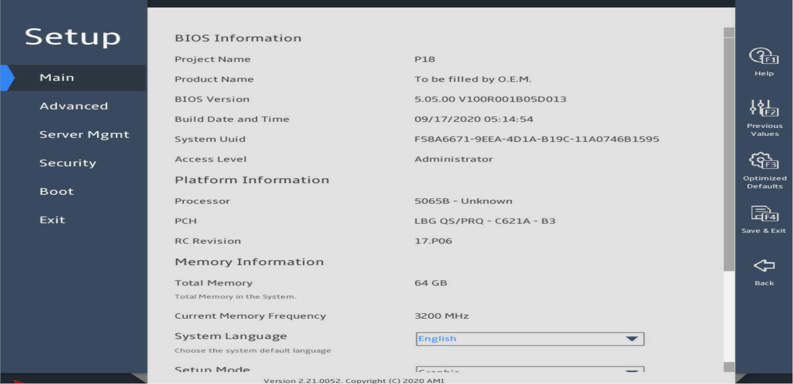
2. Select Advanced > Intel(R) Virtual RAID on CPU, as shown in Figure 68.
The Intel(R) Virtual RAID on CPU option is displayed on the advanced page only when the VMD controller has been enabled. For information about enabling the VMD controller, see H3C Servers Storage Controller User Guide.
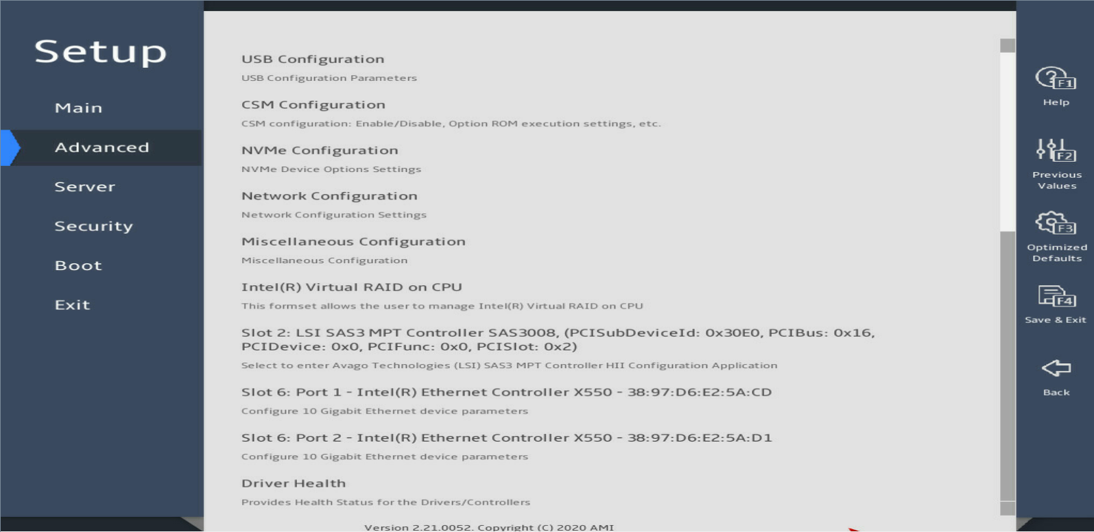
3. View the VROC PreOS version (the first two digits) on the NVMe RAID overview page. As shown in Figure 69, the VROC PreOS version is 7.5.
Figure 69 NVMe RAID overview page

Procedure
1. Run Intel® Virtual RAID on CPU to view NVMe drives.
|
|
IMPORTANT: Install and use Intel® Virtual RAID on CPU according to the guide provided with the tool kit. To obtain Intel® Virtual RAID on CPU, use one of the following methods: · Go to https://platformsw.intel.com/KitSearch.aspx to download the software. · Contact Intel Support. |
Figure 70 Viewing NVMe drives
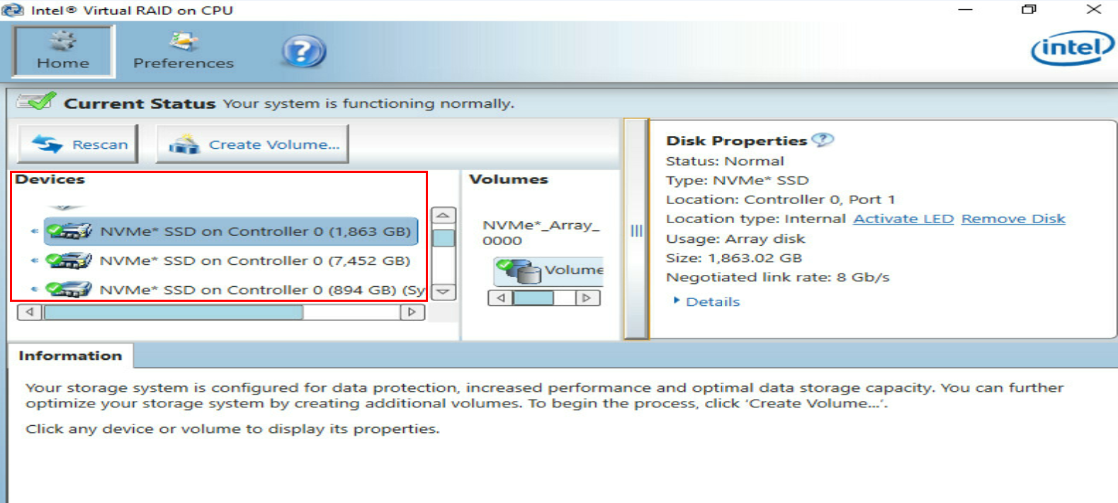
2. Select the NVMe drive to be removed from the Devices list and identify the drive location.
This procedure removes the NVMe drive from Controller 0,Port1.
Figure 71 Removing the NVMe drive
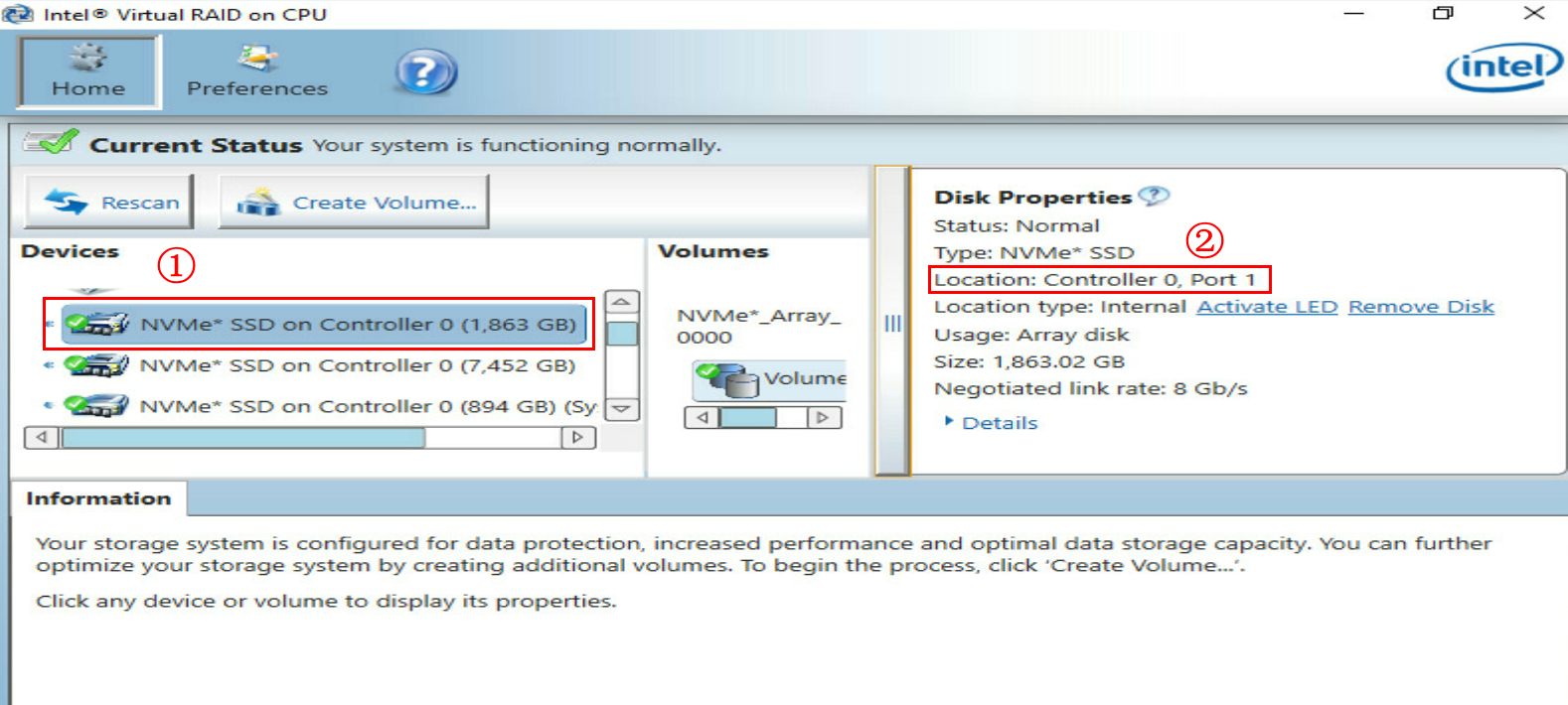
3. Stop the services on the NVMe drive.
¡ If the RAID rebuild is complete, a hot spare becomes the member drive in the RAID, go to step 5.
Figure 72 RAID rebuild completed
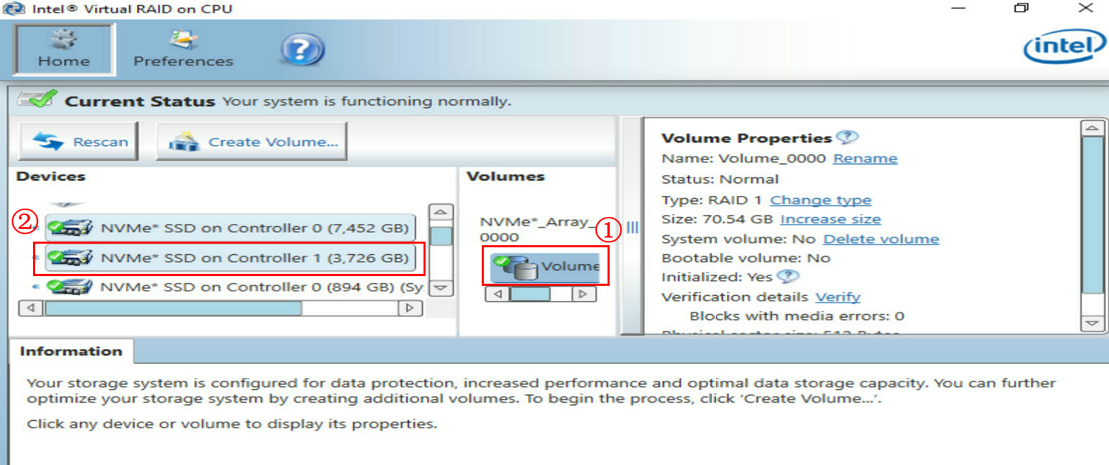
¡ If the RAID rebuild is in progress, wait the RAID rebuild to complete.
|
|
CAUTION: Do not perform any operations on the NVMe drive when the RAID rebuild is in progress. |
Figure 73 RAID rebuild in progress

5. Click Activate LED for the drive. The Fault/UID LED on the physical drive will turn steady blue for 10 seconds and then turn off automatically. The Present/Active LED will be steady green.
Figure 74 Activating the LED for the NVMe drive
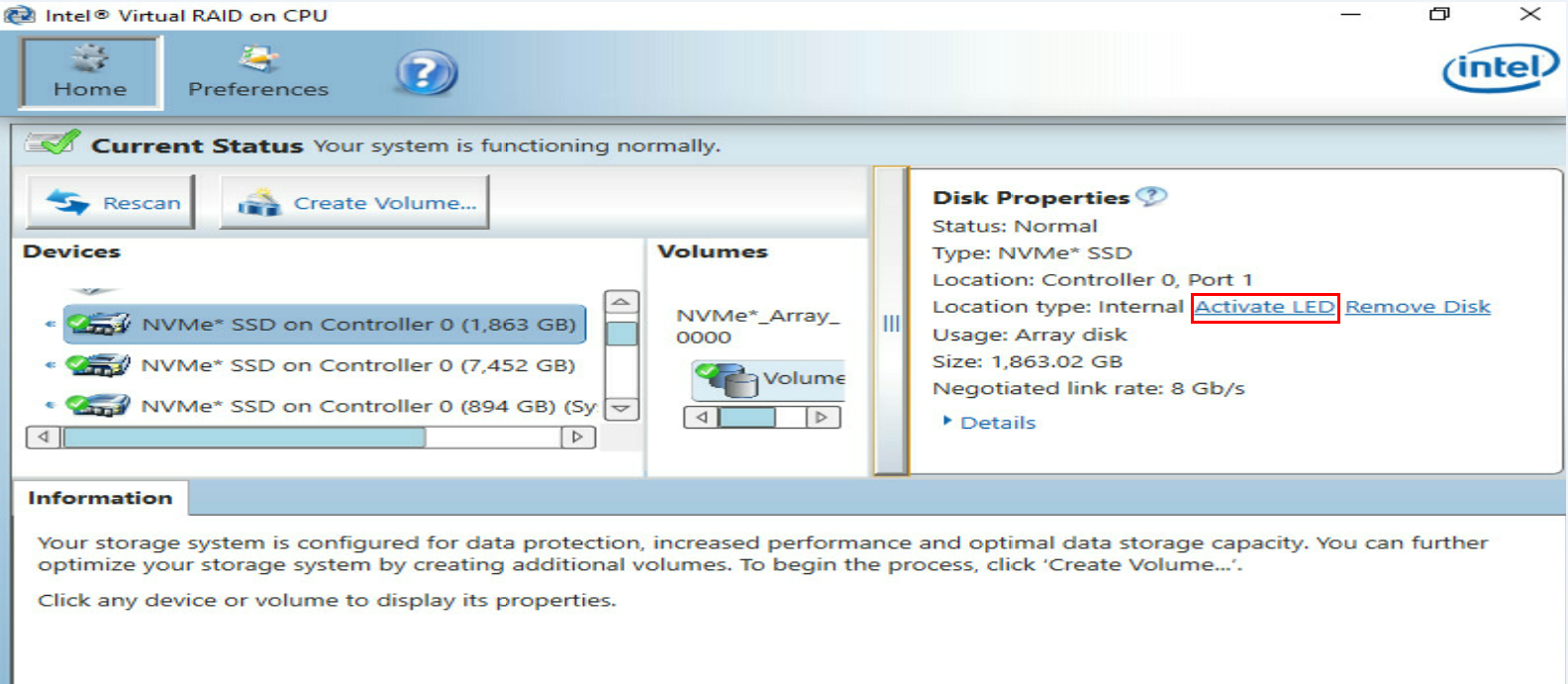
Performing a hot removal in Linux
1. Execute the lsblk | grep nvme command to identify the name of the NVMe drive to be removed.
This procedure uses drive nvme2n1 as an example.
Figure 75 Identifying the name of the NVMe drive to be removed
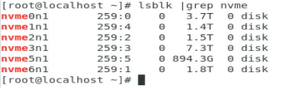
2. Stop the services on the NVMe drive.
a. Execute the df -h command to identify the mounting status of the NVMe drive. As shown in Figure 76, the drive has been mounted.
Figure 76 Viewing the mounting status of the NVMe drive
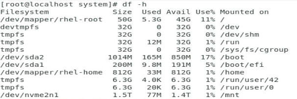
b. Execute the umount /dev/nvme2n1 command to unmount the drive. As shown in Figure 77, the drive has been unmounted.
Figure 77 Unmounting the NVMe drive
![]()
4. (Optional.) If the NVMe drive is in a RAID setup with hot spares and faulty, execute the cat /proc/mdstat command to view the RAID rebuild status.
¡ If the RAID rebuild is complete, a hot spare becomes the member drive in the RAID, go to step 5.
Figure 78 RAID rebuild completed
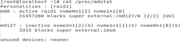
¡ If the RAID rebuild is in progress, wait the RAID rebuild to complete.
|
|
CAUTION: Do not perform any operations on the NVMe drive when the RAID rebuild is in progress. |
Figure 79 RAID rebuild in progress
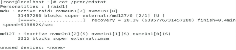
5. (Optional.) Remove the drive from the container. Skip this step for an NVMe drive that is not in a RAID setup.
a. Execute the mdadm –r /dev/md/imsm0 /dev/nvme2n1 command to remove the drive from the container, as shown in Figure 80.
Figure 80 Removing the NVMe drive from the container
![]()
b. Execute the cat /proc/mdstat command to check whether the drive has been removed from the container. As shown in Figure 81, the drive has been removed from the container.
Figure 81 Verifying the drive removal status
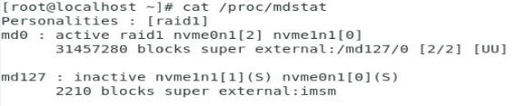
6. Identify the location of the NVMe drive on the server.
a. Execute the find /sys/devices –iname nvme2n1 command to identify the bus number of the drive. As shown in Figure 82, the bus number for the drive is 10000:04:00.0.
Figure 82 Identifying the bus number
![]()
b. Execute the lspci –vvs 10000:04:00.0 command to identify the PCIe slot number based on the bus number. As shown in Figure 83, the PCIe slot is 123.
Figure 83 Identifying the PCIe slot number
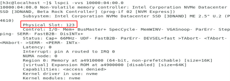
c. Identify the physical slot number of the drive.
# Log in to HDM.
# Select Hardware Summary > NVMe and then identify the physical slot number of the drive based on the PCIe slot number. In this example, the physical slot is Box3-3.
Figure 84 Identifying the physical slot number
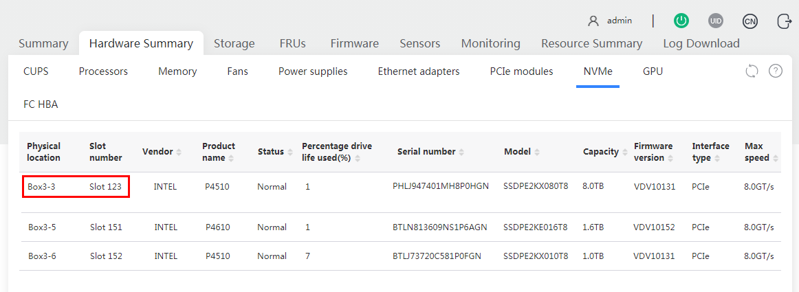
7. Remove the NVMe drive. For more information about the removal procedure, see "Removing an NVMe drive."
Performing a hot removal in VMware
1. Identify the NVMe drive to be removed. As shown in Figure 85, click the Devices tab on the VMware ESXi management GUI.
This procedure uses drive t10.NVMe__INTEL_SSDPE2KE016T8_______BTLN813609NS1P6AGN_00000001 as an example.
Figure 85 Identifying the NVMe drive to be removed
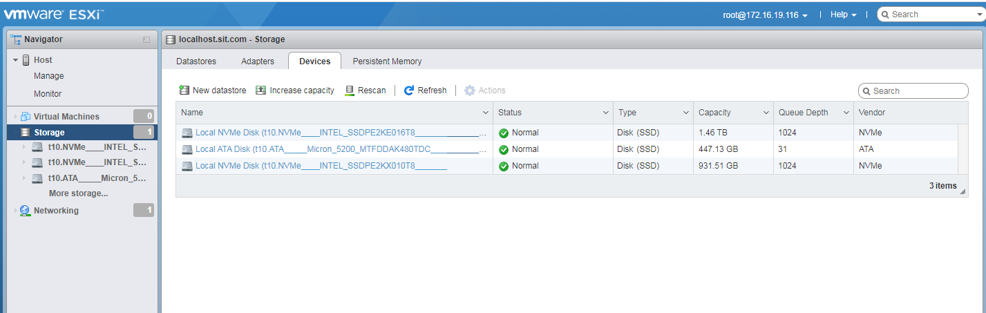
2. Stop the services on the NVMe drive to be removed.
3. Click the drive name to view its mounting status.
¡ If partitions exist, go to step 4 to unmount the drive.
¡ If no partition exists, turn on the LED on the drive. For the detailed procedure, see step 5.
Figure 86 Viewing the mounting status
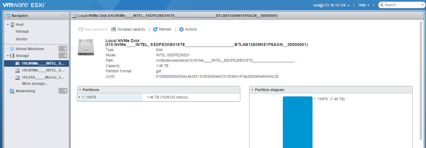
4. (Optional.) Unmount the NVMe drive.
a. Click the Datastores tab to view the mounted NVMe drives.
Figure 87 Viewing the mounted NVMe drives
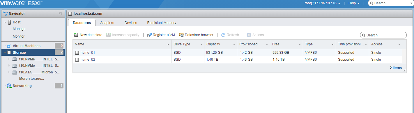
b. Click the drive and identify its name. Make sure it is the drive you are to remove.
Figure 88 Viewing the drive name
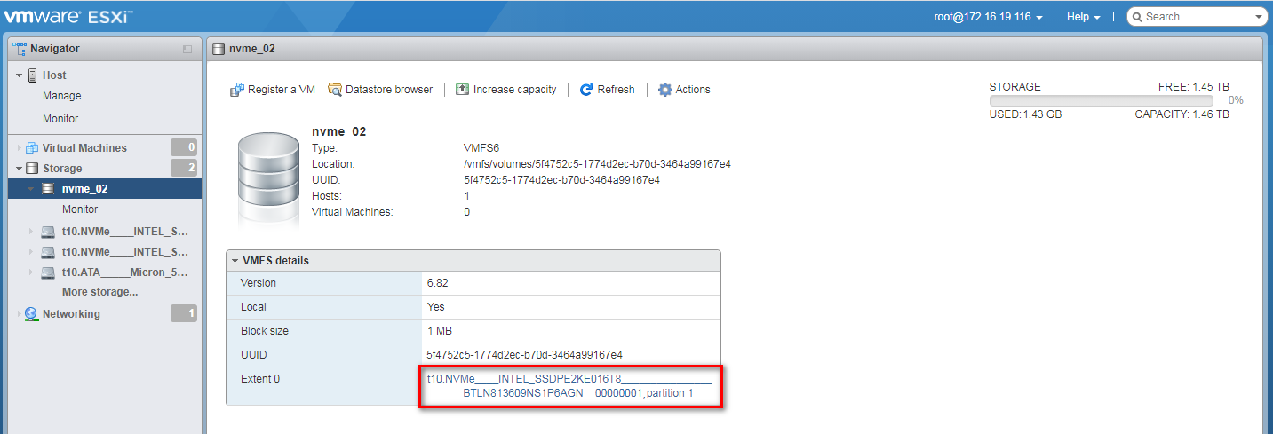
c. Click Actions and then select Unmount from the dropdown list. In the dialog box that opens, click Yes.
Figure 89 Unmounting the NVMe drive
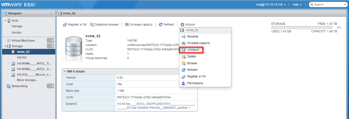
Figure 90 Confirming the drive removal
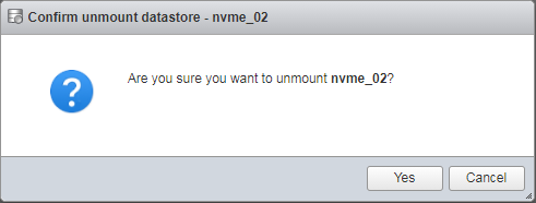
d. Click the Datastores tab to view the drive removal status. As shown in Figure 91, the drive capacity is 0 B, indicating that the NVMe drive has been removed successfully.
Figure 91 Viewing the drive removal status
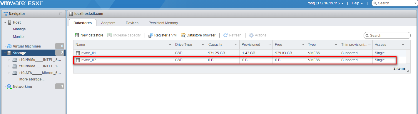
5. Turn on the LED for the NVMe drive to identify the location of the NVMe drive on the server.
a. Install the Intel VMD LED management command line tool on the server. To obtain the Intel VMD LED management command line tool, access https://downloadcenter.intel.com/download/28288/Intel-VMD-ESXi-Tools.
b. Execute the esxcfg-mpath –L command to view the SCSI ID for the NVMe drive. As shown in Figure 92, the VMD adapter for the drive is vmhba2 and the drive number is 1.
Figure 92 Viewing the SCSI ID for the NVMe drive
![]()
b. Execute the cd /opt/intel/bin/ command to access the directory where the Intel VMD LED management command line tool resides.
c. Execute the /intel-vmd-user set-led vmhba2 –d 1 –l identify command to turn on the LED for the drive.
Figure 93 Turning on the LED for the drive
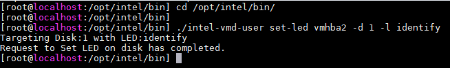
d. Observe the LEDs on the NVMe drive. You can remove the NVMe drive after the Fault/UID LED turns steady blue and the Present/Active LED turns steady green.
6. Remove the NVMe drive. For more information about the removal procedure, see "Removing an NVMe drive."
Performing a managed hot removal in Windows
1. Run Intel® Virtual RAID on CPU to view NVMe drives. For more information, see step 1 in "Performing a hot removal in Windows."
2. Select the NVMe drive to be removed from the Devices list and identify its location on the server. For more information, see step 2 in "Performing a hot removal in Windows."
3. Stop the services on the NVMe drive.
4. (Optional.) If the NVMe drive is in a RAID setup configured with hot spares, view the RAID rebuild status. For more information, see step 4 in "Performing a hot removal in Windows."
5. Click Activate LED to turn on the Fault/UID LED on the drive, as shown by callout 1 in Figure 94. The Fault/UID LED on the physical drive will turn steady blue for 10 seconds and turn off automatically. The Present/Active LED will turn steady green.
6. Click Remove Disk, as shown by callout 2 in Figure 94.
Figure 94 Removing the NVMe drive
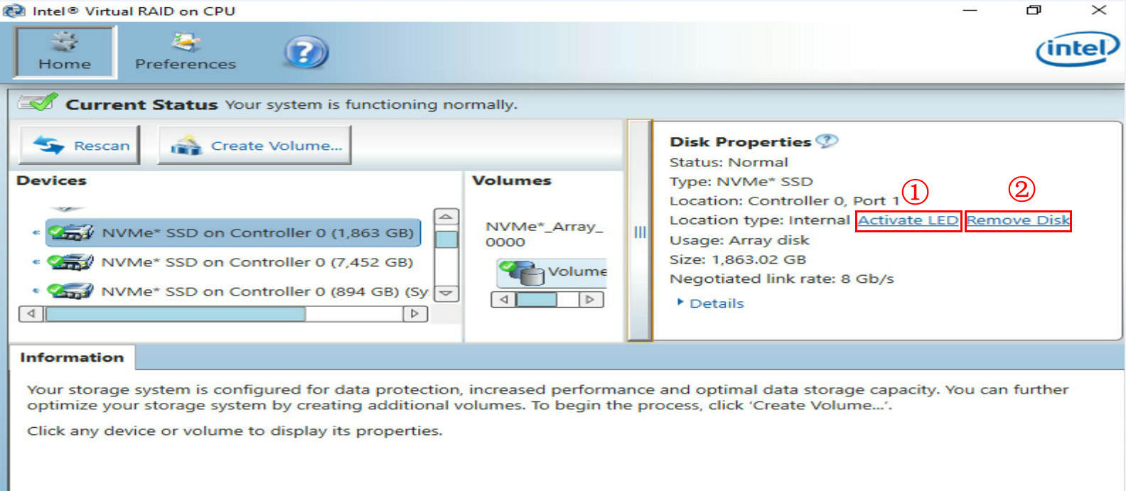
7. Observe the LEDs on the NVMe drive. Make sure the Fault/UID LED is steady blue and the Present/Active LED is steady green.
8. Make sure the NVMe drive is removed from the Devices list of Intel® Virtual RAID on CPU.
9. Remove the NVMe drive. For more information about the removal procedure, see "Removing an NVMe drive."
Performing a managed hot removal in Linux
1. Identify the name of the NVMe drive to be removed. For more information, see step 1 in "Performing a hot removal in Linux."
2. Stop the services on the NVMe drive.
3. (Optional.) If the NVMe drive is a pass-through drive, view the mounting status of the drive. If the drive has been mounted, first unmount it. For more information, see step 3 in "Performing a hot removal in Linux."
4. (Optional.) If the NVMe drive is in a RAID setup configured with hot spares, view the RAID rebuild status. For more information, see step 4 in "Performing a hot removal in Linux." Then remove the drive from the container. For more information, see step 5 in "Performing a hot removal in Linux."
5. (Optional.) On an SUSE15, SUSE12SP4, or RHEL 7.6 operating system, the Fault/UID LED on the server remains steady blue after you execute the unmounting command on the system. For easy location of the drive slot when the server runs such an operating system, manually create the ledmon service.
a. Execute the vim /usr/lib/systemed/system/ledmon.service command to create a ledmon service file.
Figure 95 Creating a ledmon service file
![]()
b. Add settings to the ledmon service file.
Figure 96 Adding settings to the ledmon service file
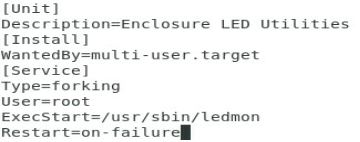
c. Start the ledmon service server.
Figure 97 Starting the ledmon service server

6. Unmount the NVMe drive and verify the NVMe drive status:
a. Execute the echo 1 > /sys/block/nvme2n1/device/device/remove command to unmount drive nvme2n1 from the operating system.
Figure 98 Unmounting the NVMe drive
![]()
b. Execute the lsblk command to view the mounted NVMe drives. Drive nvme2n1 is not in the command output, indicating that it is unmounted successfully.
Figure 99 Verifying the NVMe drive status
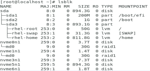
7. Observe the LEDs on the NVMe drive. You can remove the NVMe drive after the Fault/UID LED is steady amber and the Present/Active LED is steady green.
8. Remove the NVMe drive. For more information about the removal procedure, see "Removing an NVMe drive."
Installing an NVMe drive
Performing a hot installation in Windows
2. Observe the LEDs on the NVMe drive. The NVMe drive is present in the slot without any faults if the Present/Active LED is steady green and the Fault/UID LED is off.
3. Run Intel® Virtual RAID on CPU to view the operating status of the NVMe drive.
As shown in Figure 100, the NVMe drive is displayed in the Devices list and the drive properties is consistent with the actual drive specification, indicating that the NVMe drive is installed successfully.
Figure 100 Verifying the status of the installed NVMe drive in Windows

|
|
IMPORTANT: Install NVMe drives one after another. Only after an NVMe drive is installed and recognized by the system, can you install another one. |
Performing a hot installation in Linux
1. Install an NVMe drive. For more information about the installation procedure, see "Installing an NVMe drive."
2. Observe the LEDs on the NVMe drive. The NVMe drive is present in the slot without any faults if the Present/Active LED is steady green and the Fault/UID LED is off.
3. View the installation status of the NVMe drive in Linux.
¡ If the NVMe drive is removed by using the hot removal procedure, execute the lspci –vvs with the bus number of the drive, for example, 10000:04:00.0. As shown in Figure 101, information about the NVMe drive with bus number 10000:04:00.0 is displayed, indicating that the drive is installed successfully.
Figure 101 Viewing the NVMe drive installation status in Linux (1)
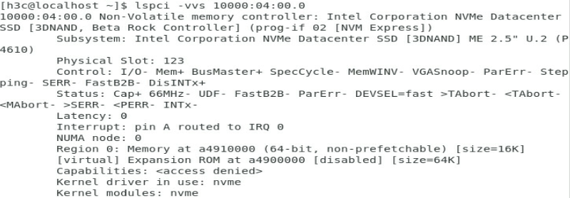
¡ If the NVMe drive is removed by using the managed hot removal procedure, execute the lsblk command to view information about the drives. As shown in Figure 102, NVMe drive nvme2n1 is displayed in the command output, indicating that the drive is installed successfully.
Figure 102 Viewing the NVMe drive installation status in Linux (2)
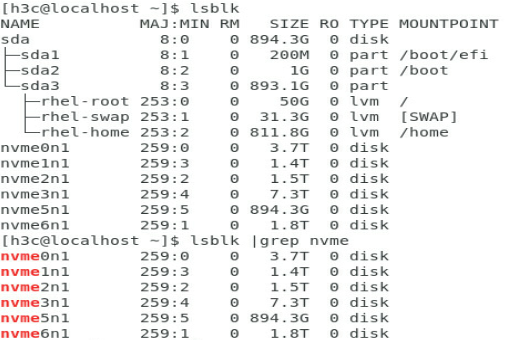
Performing a hot installation in VMware
1. Install an NVMe drive. For more information about the installation procedure, see "Installing an NVMe drive."
2. Observe the LEDs on the NVMe drive. The NVMe drive is present in the slot without any faults when the Present/Active LED is steady green and the Fault/UID LED is off.
3. Execute the esxcfg-mpath –L command to view the status of the installed NVMe drive in VMware.
As shown in Figure 103, drive t10.NVMe__INTEL_SSDPE2KE016T8_______BTLN813609NS1P6AGN_00000001 is displayed in the command output, so the NVMe drive is installed successfully.
Figure 103 Verifying the status of the installed NVMe drive in VMware
![]()
Verifying the RAID status of the installed NVMe drive
After an NVMe drive is installed, verify the following items:
· If the removed NVMe drive is a member drive in a RAID setup that offers redundancy, does not have any hot spares, and is enabled with RAID rebuild, the storage controller will automatically rebuild the RAID.
¡ In a Linux operating system, execute the cat /proc/mdstat command to view the RAID rebuild status.
Figure 104 RAID rebuild completed
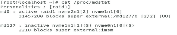
Figure 105 RAID rebuild in progress
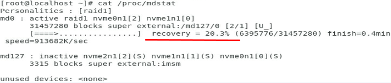
¡ In a Windows operating system, run Intel® Virtual RAID on CPU to view the RAID rebuild status.
Figure 106 RAID rebuild completed

Figure 107 RAID rebuild in progress
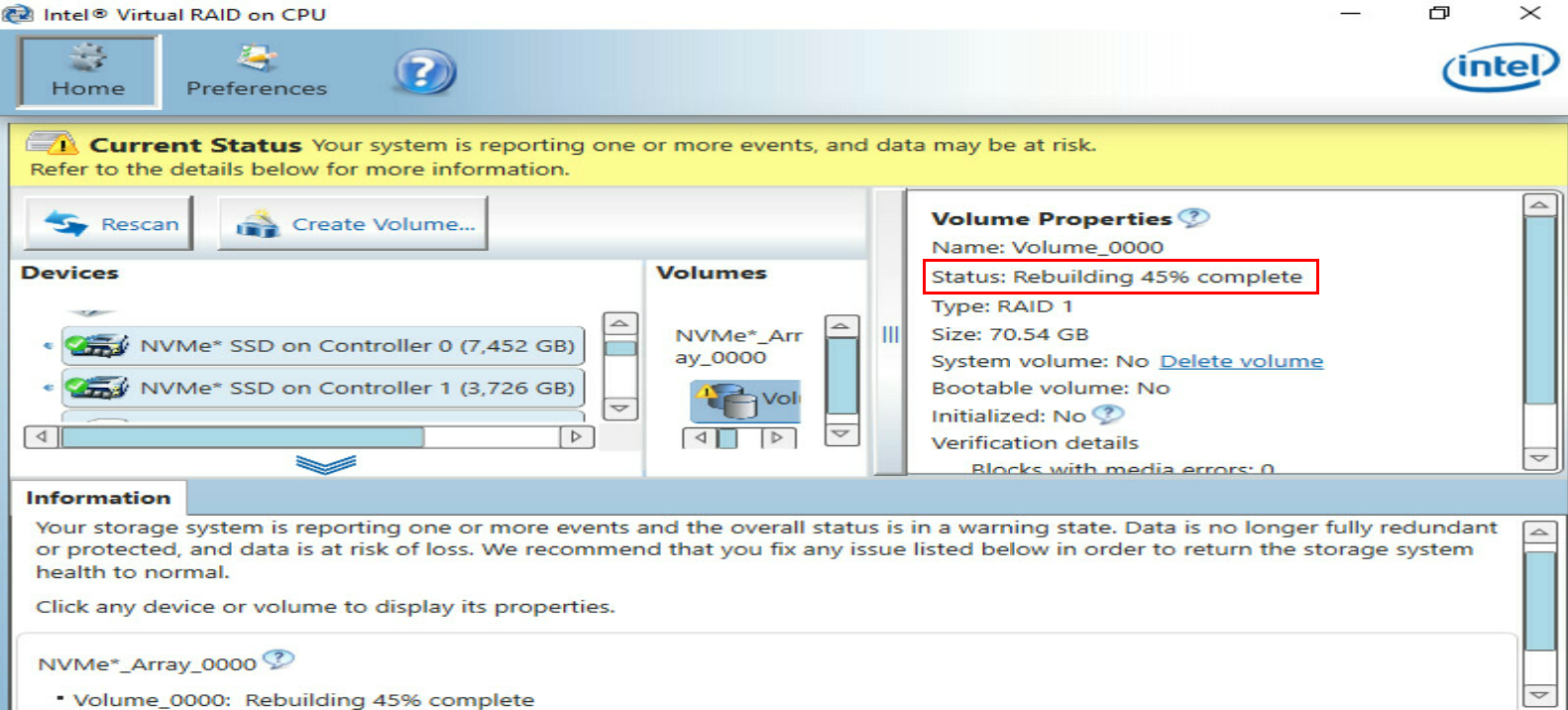
· If the removed NVMe drive is a pass-through drive, the new NVMe drive functions as a pass-through drive.
· If the removed NVMe drive is a member drive in a RAID setup that does not offer redundancy, the new NVMe drive functions as a pass-through drive. You can add the new NVMe drive to a RAID as needed.
· If the removed NVMe drive is a member drive in a RAID setup that offers redundancy, does not have hot spares, and is disabled with RAID rebuild, the new NVMe drive functions as a pass-through drive. You can add the new NVMe drive to a RAID as needed.
· If the removed NVMe drive is a member drive in a RAID setup that offers redundancy and is configured with hot spares, the new NVMe drive functions as a pass-through drive. You can add the new NVMe drive to a RAID as needed.
For more information about RAID, see the storage controller user guide.
Appendix D Managed removal of OCP network adapters
Before you begin
Before you perform a managed removal of an OCP network adapter, perform the following tasks:
· Use the OS compatibility query tool to obtain operating systems that support managed removal of OCP network adapters.
· Make sure the BIOS version is 5.15 or higher, the HDM version is 2.29 or higher, and the CPLD version is V2002 or higher.
Performing a hot removal
This section uses an OCP network adapter in slot 16 as an example.
To perform a hot removal:
1. Access the operating system.
2. Execute the dmidecode -t 9 command to search for the bus address of the OCP network adapter. As shown in Figure 108, the bus address of the OCP network adapter in slot 16 is 0000:31:00.0.
Figure 108 Searching for the bus address of an OCP network adapter by slot number
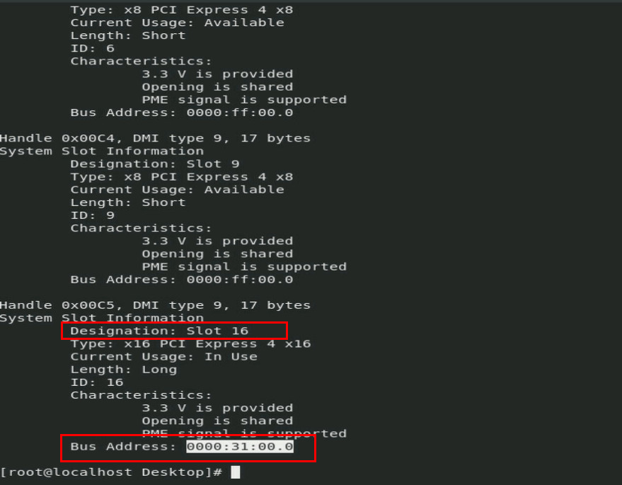
3. Execute the echo 0 > /sys/bus/pci/slots/slot number/power command, where slot number represents the number of the slot where the OCP network adapter resides.
Figure 109 Executing the echo 0 > /sys/bus/pci/slots/slot number/power command
![]()
4. Identify whether the OCP network adapter has been disconnected:
¡ Observe the OCP network adapter LED. If the LED is off, the OCP network adapter has been disconnected.
¡ Execute the lspci –vvv –s 0000:31:00.0 command. If no output is displayed, the OCP network adapter has been disconnected.
Figure 110 Identifying OCP network adapter status
![]()
5. Replace the OCP network adapter.
6. Identify whether the OCP network adapter has been connected:
¡ Observe the OCP network adapter LED. If the LED is on, the OCP network adapter has been connected.
¡ Execute the lspci –vvv –s 0000:31:00.0 command. If an output is displayed, the OCP network adapter has been connected.
Figure 111 Identifying OCP network adapter status
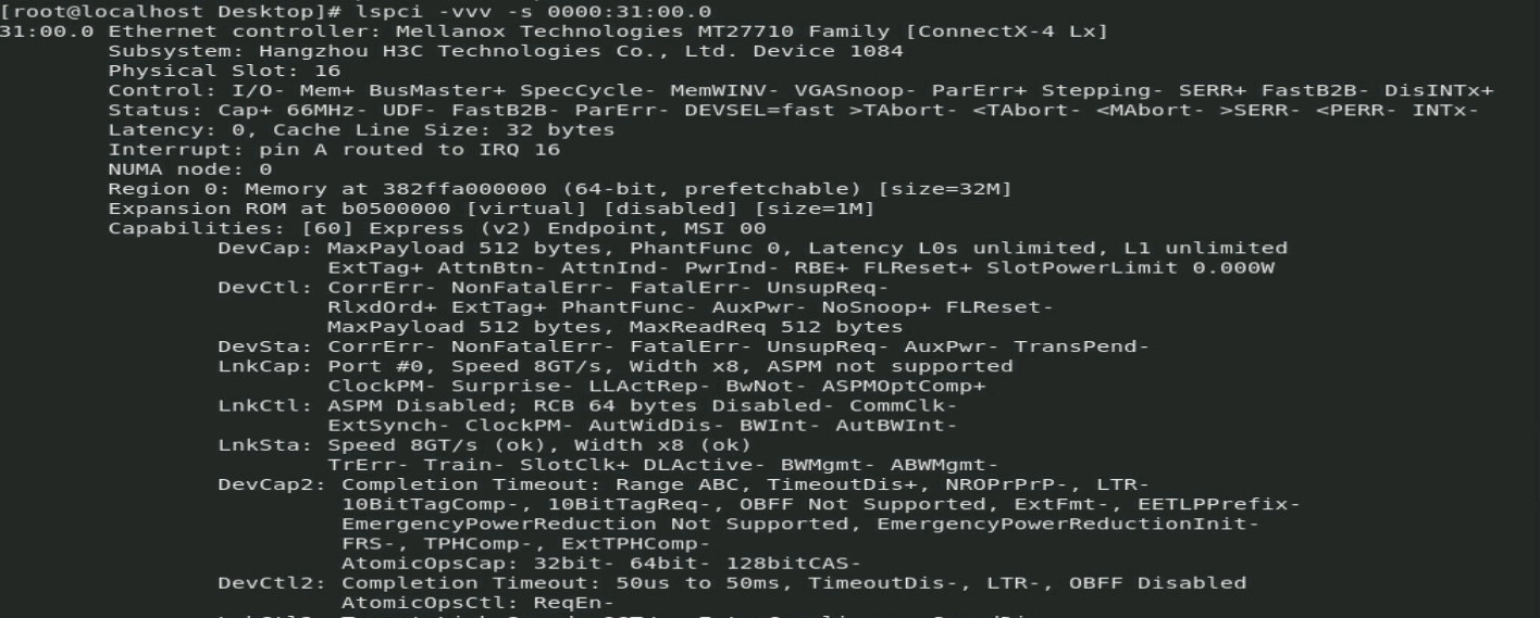
7. Identify whether any exception exists. If any exception occurred, contact H3C Support.
Appendix E Environment requirements
About environment requirements
The operating temperature requirements for the server vary depending on the server model and hardware configuration. When the general and component-based requirements conflict, use the component-based requirement.
Be aware that the actual maximum operating temperature of the server might be lower than what is stated because of poor site cooling performance. In a real data center, the server cooling performance might decrease because of adverse external factors, including poor cabinet cooling performance, high power density inside the cabinet, or insufficient spacing between devices.
General environment requirements
|
Item |
Specifications |
|
Operating temperature |
Minimum: 5°C (41°F) Maximum: 45°C (113°F)
The maximum temperature varies by hardware option presence. For more information, see "Operating temperature requirements." |
|
Storage temperature |
–40°C to +70°C (–40°F to +158°F) |
|
Operating humidity |
8% to 90%, noncondensing |
|
Storage humidity |
5% to 95%, noncondensing |
|
Operating altitude |
–60 m to +3000 m (–196.85 ft to +9842.52 ft) The allowed maximum temperature decreases by 0.33 °C (32.59°F) as the altitude increases by 100 m (328.08 ft) from 900 m (2952.76 ft) |
|
Storage altitude |
–60 m to +5000 m (–196.85 ft to +16404.20 ft) |
Operating temperature requirements
General guidelines
When a fan fails, the maximum server operating temperature decreases by 5°C (41°F). The GPU performance and performance of processors with a TDP of more than 165 W might decrease.
If a mid drive or mid GPU adapter is installed, you cannot install processors with a TDP of more than 165 W.
8SFF and 16SFF drive configuration
The 8SFF drives installed in slots 0 to 7. For more information about drive slots, see "Drive numbering."
Table 20 Operating temperature requirements
|
Maximum server operating temperature |
Hardware options |
|
30°C (86°F) |
All hardware options are supported. |
|
35°C (95°F) |
GPU-V100S-32G GPU modules are not supported. |
|
40°C (104°F) |
The following hardware options are not supported: · GPU modules. · NVMe drives. · Mid and rear drives. · PMem 200 memory. · Processors with a TDP of more than 165 W. · DPS-1600AB-13 R power supply. |
|
45°C (113°F) |
The following hardware options are not supported: · GPU modules. · NVMe drives. · Mid and rear drives. · PMem 200 memory. · Processors with a TDP of more than 165 W. · DPS-1600AB-13 R power supply. · 25G or above network adapters, including OCP and PCIe network adapters. |
8LFF drive configuration
Table 21 Operating temperature requirements
|
Maximum server operating temperature |
Hardware options |
|
30°C (86°F) |
With a GPU-V100S-32G GPU module installed in the server, processors with a TDP of more than 200 W are not supported. |
|
35°C (95°F) |
GPU-V100S-32G GPU modules are not supported. |
|
40°C (104°F) |
The following hardware options are not supported: · GPU modules. · NVMe drives. · Mid and rear drives. · PMem 200 memory. · Processors with a TDP of more than 165 W. · DPS-1600AB-13 R power supply. |
|
45°C (113°F) |
The following hardware options are not supported: · GPU modules. · NVMe drives. · Mid and rear drives. · PMem 200 memory. · Processors with a TDP of more than 165 W. · DPS-1600AB-13 R power supply. · 25G or above network adapters, including OCP and PCIe network adapters. |
12LFF, 25SFF, and 24SFF drive configuration
|
|
CAUTION: The 12LFF, 25SFF, or 24SFF drive configuration is not supported when the temperature is 45°C (113°F). |
Table 22 Operating temperature requirements
|
Maximum server operating temperature |
Hardware options |
|
30°C (86°F) |
The following hardware options are not supported: · GPU-V100S-32G GPU modules. · Mid GPU adapters. |
|
35°C (95°F) |
The following hardware options are not supported: · GPU-V100S-32G GPU modules. · DPS-1600AB-13 R power supplies. · With a GPU-T4 GPU module installed in the server, the processors with a TDP of more than 230 W are not supported. · Mid GPU adapters. |
|
40°C (104°F) |
The following hardware options are not supported: · GPU modules. · NVMe drives. · Mid and rear drives. · PMem 200 memory. · Processors with a TDP of more than 165 W. · DPS-1600AB-13 R power supply. |
Appendix F Product recycling
New H3C Technologies Co., Ltd. provides product recycling services for its customers to ensure that hardware at the end of its life is recycled. Vendors with product recycling qualification are contracted to New H3C to process the recycled hardware in an environmentally responsible way.
For product recycling services, contact New H3C at
· Tel: 400-810-0504
· E-mail: [email protected]
· Website: http://www.h3c.com
Appendix G Glossary
|
Description |
|
|
B |
|
|
BIOS |
Basic input/output system is non-volatile firmware pre-installed in a ROM chip on a server's management module. The BIOS stores basic input/output, power-on self-test, and auto startup programs to provide the most basic hardware initialization, setup and control functionality. |
|
C |
|
|
CPLD |
Complex programmable logic device is an integrated circuit used to build reconfigurable digital circuits. |
|
E |
|
|
Ethernet adapter |
An Ethernet adapter, also called a network interface card (NIC), connects the server to the network. |
|
F |
|
|
FIST |
Fast Intelligent Scalable Toolkit provided by H3C for easy and extensible server management. It can guide users to configure a server quickly with ease and provide an API interface to allow users to develop their own management tools. |
|
G |
|
|
GPU module |
Graphics processing unit module converts digital signals to analog signals for output to a display device and assists processors with image processing to improve overall system performance. |
|
H |
|
|
HDM |
Hardware Device Management is the server management control unit with which administrators can configure server settings, view component information, monitor server health status, and remotely manage the server. |
|
A module that supports hot swapping (a hot-swappable module) can be installed or removed while the server is running without affecting the system operation. |
|
|
K |
|
|
KVM |
KVM is a management method that allows remote users to use their local video display, keyboard, and mouse to monitor and control the server. |
|
N |
|
|
NVMe VROC module |
A module that works with Intel VMD to provide RAID capability for the server to virtualize storage resources of NVMe drives. |
|
R |
|
|
RAID |
Redundant array of independent disks (RAID) is a data storage virtualization technology that combines multiple physical hard drives into a single logical unit to improve storage and security performance. |
|
Redundancy |
A mechanism that ensures high availability and business continuity by providing backup modules. In redundancy mode, a backup or standby module takes over when the primary module fails. |
|
S |
|
|
Security bezel |
A locking bezel mounted to the front of a server to prevent unauthorized access to modules such as hard drives. |
|
U |
A unit of measure defined as 44.45 mm (1.75 in) in IEC 60297-1. It is used as a measurement of the overall height of racks, as well as equipment mounted in the racks. |
|
UniBay drive backplane |
A UniBay drive backplane supports both SAS/SATA and NVMe drives. |
|
V |
|
|
VMD |
VMD provides hot removal, management and fault-tolerance functions for NVMe drives to increase availability, reliability, and serviceability. |
Appendix H Acronyms
|
Acronym |
Full name |
|
B |
|
|
BIOS |
|
|
C |
|
|
CMA |
Cable Management Arm |
|
CPLD |
|
|
D |
|
|
DCPMM |
Data Center Persistent Memory Module |
|
DDR |
Double Data Rate |
|
DIMM |
Dual In-Line Memory Module |
|
DRAM |
Dynamic Random Access Memory |
|
F |
|
|
FIST |
|
|
G |
|
|
GPU |
|
|
H |
|
|
HBA |
Host Bus Adapter |
|
HDD |
Hard Disk Drive |
|
HDM |
|
|
I |
|
|
IDC |
Internet Data Center |
|
iFIST |
integrated Fast Intelligent Scalable Toolkit |
|
K |
|
|
KVM |
Keyboard, Video, Mouse |
|
L |
|
|
LRDIMM |
Load Reduced Dual Inline Memory Module |
|
N |
|
|
NCSI |
Network Controller Sideband Interface |
|
NVMe |
Non-Volatile Memory Express |
|
P |
|
|
PCIe |
Peripheral Component Interconnect Express |
|
POST |
Power-On Self-Test |
|
R |
|
|
RDIMM |
Registered Dual Inline Memory Module |
|
S |
|
|
SAS |
Serial Attached Small Computer System Interface |
|
SATA |
Serial ATA |
|
SD |
Secure Digital |
|
SDS |
Secure Diagnosis System |
|
SFF |
Small Form Factor |
|
sLOM |
Small form factor Local Area Network on Motherboard |
|
SSD |
Solid State Drive |
|
T |
|
|
TCM |
Trusted Cryptography Module |
|
TDP |
Thermal Design Power |
|
TPM |
Trusted Platform Module |
|
U |
|
|
UID |
Unit Identification |
|
UPI |
Ultra Path Interconnect |
|
UPS |
Uninterruptible Power Supply |
|
USB |
Universal Serial Bus |
|
V |
|
|
VROC |
Virtual RAID on CPU |
|
VMD |
Volume Management Device |
