| Title | Size | Download |
|---|---|---|
| 01-Text | 1.24 MB |
Removable components and compatibility matrixes
Expansion module specifications
100/1000BASE-T management Ethernet port
WX5860X device port status LEDs
Port LED on an expansion module
1 Product overview
Product models
This document is applicable to the WX5800X series access controllers. Table1-1 describes the WX5800X series access controller models.
Table1-1 WX5800X series access controller models
|
Product series |
Product code |
Model |
Remarks |
|
WX5800X series |
EWP-WX5860X |
WX5860X |
Non-PoE model |
Technical specifications
Table1-2 Technical specifications
|
Item |
Specification |
|
Dimensions (H × W × D) |
88.1 × 440 × 660 mm (3.47 × 17.32 × 25.98 in) |
|
Weight |
< 22.9 kg (50.49 lb) |
|
Console port |
1, control port, 9600 bps |
|
USB port |
2 (USB2.0) |
|
Management port |
1 × 100/1000BASE-T management Ethernet port |
|
Memory |
64GB DDR4 |
|
Storage media |
32GB eMMC memory |
|
Rated voltage range |
· PSR650B-12A1: 100 to 240 VAC @ 50 or 60 Hz · PSR650B-12D1: –40 to –60 VDC |
|
System power consumption |
< 502 W |
|
Operating temperature |
0°C to 45°C (32°F to 113°F) |
|
Operating humidity |
5% RH to 95% RH, noncondensing |
Chassis views
WX5860X
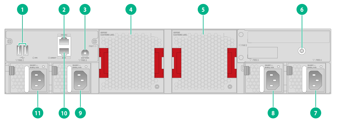
Front, rear, and side views
|
(1) USB ports |
(2) Serial console port |
|
(3) SHUT DOWN button LED |
(4) Fan tray 1 |
|
(5) Fan tray 2 |
(6) Grounding screw (auxiliary grounding point 2) |
|
(7) Power supply 4 |
(8) Power supply 3 |
|
(9) Power supply 2 |
(10) Management Ethernet port |
|
(11) Power supply 1 |
|
|
|
NOTE: Pressing the SHUT DOWN button LED for more than 15 milliseconds powers on the device. If you press and hold the button LED for more than 2 seconds, the LED is fast flashing at 1 Hz. You must wait for the device to notify the x86 operating system to shut down, and you can power off the device only when the LED turns off. |
|
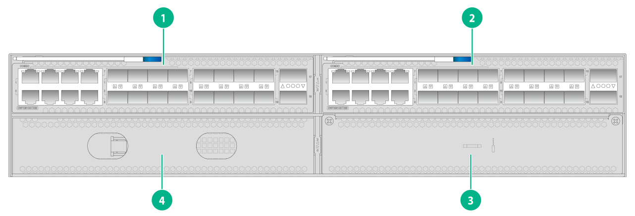
(1) Expansion slot 1 |
(2) Expansion slot 2 |
|
(3) Expansion slot 4 (reserved) |
(4) Expansion slot 3 (reserved) |
The device comes with expansion slot 1 empty and the other expansion slots each installed with a filler panel. You can install expansion modules only in expansion slots 1 and 2. Expansion slots 3 and 4 are reserved. You can install one to two expansion modules for the device as required. In Figure1-2, expansion modules are installed in two expansion module slots.
The device comes with power supply slot PWR1 empty and the other three power supply slots each installed with a filler panel. One power supply can meet the power requirement of the device. You can also install two, three, or four power supplies for the device to achieve 1+1, 1+2, or 1+3 redundancy, respectively. In Figure1-1, four power supplies are installed in the power supply slots.
The device comes with the two fan tray slots empty. In Figure1-1, two fan trays are installed in the fan tray slots.
|
|
CAUTION: · Do not hot swap expansion modules. Hot swapping expansion modules restarts the device. Please be cautious. · To ensure adequate heat dissipation, you must install two fan trays for the device. |
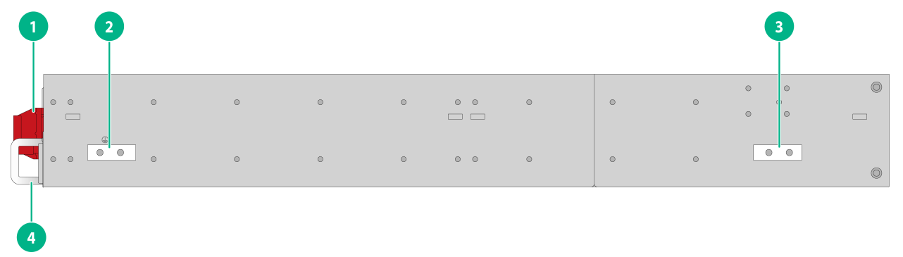
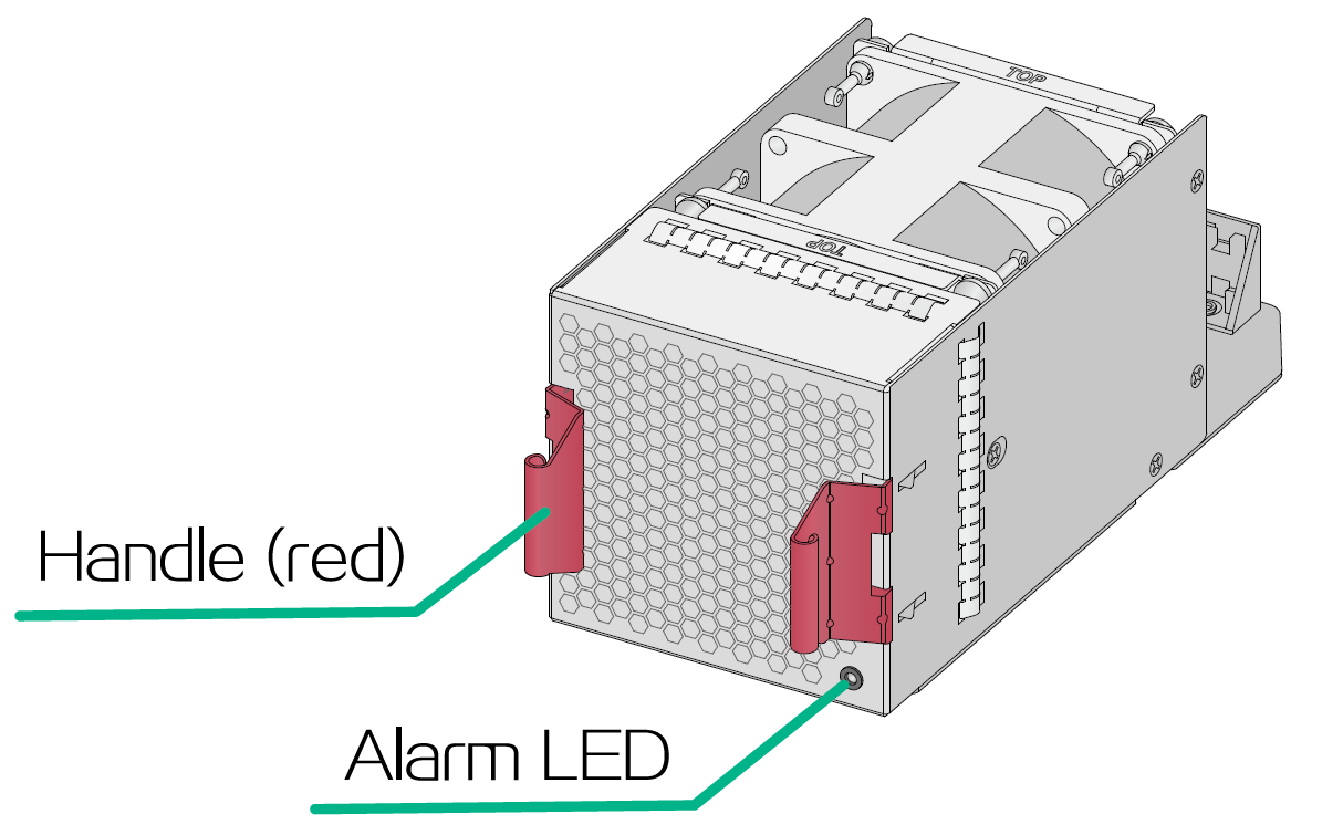
Figure1-3 Side view
|
(1) Fan tray handle |
(2) Primary grounding point |
|
(3) Auxiliary grounding point |
(4) Power supply handle |
LED locations
The device in the following figures is fully configured with AC power supplies, fan trays, and expansion modules.
Figure1-4 Front panel LED locations
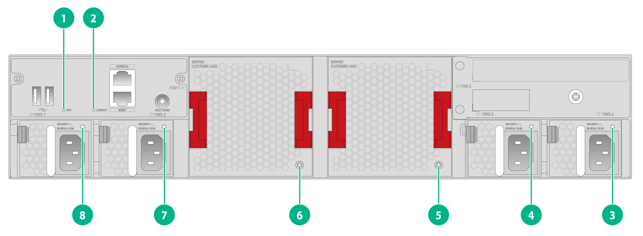
|
(1) System status LED (SYS) |
(2) Management Ethernet port LED (LINK/ACT) |
|
(3) Power supply status LEDs (3, 4, 7, and 8) |
(4) Fan tray status LEDs (5 and 6) |
Figure1-5 Rear panel LED locations
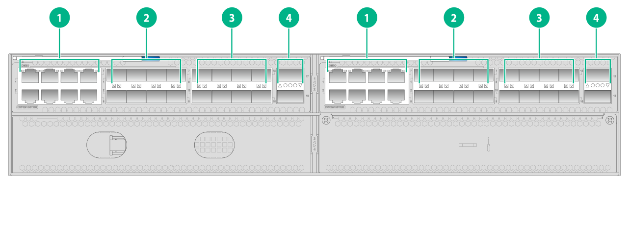
|
(1) 1000Base-T Ethernet port LEDs |
(2) SFP port LEDs |
|
(3) 10G SFP+ port LEDs |
(4) 40G QSFP+ port LEDs |
2 Removable components
Removable components and compatibility matrixes
The access controllers use modular design. Table2-1 describes the compatibility matrix between access controllers and removable components.
Table2-1 Compatibility matrix between access controllers and removable components
|
Removable components |
WX5860X |
|
Removable power supplies |
|
|
PSR650B-12A1 |
Supported |
|
PSR650B-12D1 |
Supported |
|
Removable fan trays |
|
|
LSWM1BFANSCB |
Supported |
|
Expansion modules |
|
|
EWPXM1BSTX80 |
Supported |
Table2-2 describes the compatibility matrix between expansion modules and expansion slots.
Table2-2 Compatibility matrix between expansion modules and expansion slots
|
Expansion module |
WX5860X |
|
|
Slot 1 Slot 2 |
Slot 3 Slot 4 |
|
|
EWPXM1BSTX80 |
Supported |
N/A |
The power supplies support asset management. You can use display device manuinfo command to view the name, sequence number, and vendor of the power supply you have installed on the device.
Power supplies
Power supply specifications
|
|
WARNING! When the device has power supplies in redundancy, you can replace a power supply without powering off the device. To avoid device damage and bodily injury, make sure the power supply is powered off before you replace it. |
Table2-3 Power supply specifications
|
Power supply model |
Item |
Specification |
|
PSR650B-12A1 |
Product code |
PSR650B-12A1-D |
|
Rated AC input voltage range |
100 to 240 VAC @ 50 or 60 Hz |
|
|
Output voltage |
12 V/5 V |
|
|
Max output current |
52.9 A (12 V)/3 A (5 V) |
|
|
Max output power |
650 W |
|
|
Dimensions (H × W × D) |
40.2 × 50.5 × 300 mm (1.58 × 1.99 × 11.81 in) |
|
|
Operating temperature |
–5°C to +50°C (23°F to 122°F) |
|
|
Operating humidity |
5% RH to 95% RH, noncondensing |
|
|
PSR650B-12D1 |
Product code |
PSR650B-12D1-GL |
|
Rated DC input voltage range |
–48 to –60 VDC |
|
|
Output voltage |
12 V/5 V |
|
|
Max output current |
52.9 A (12 V)/3 A (5 V) |
|
|
Max output power |
650 W |
|
|
Dimensions (H × W × D) |
40.2 × 50.5 × 300 mm (1.58 × 1.99 × 11.81 in) |
|
|
Operating temperature |
–5°C to +45°C (23°F to 113°F) |
|
|
Operating humidity |
5% RH to 95% RH, noncondensing |
Power supply views
Figure2-1 PSR650B-12A1&PSR650B-12D1
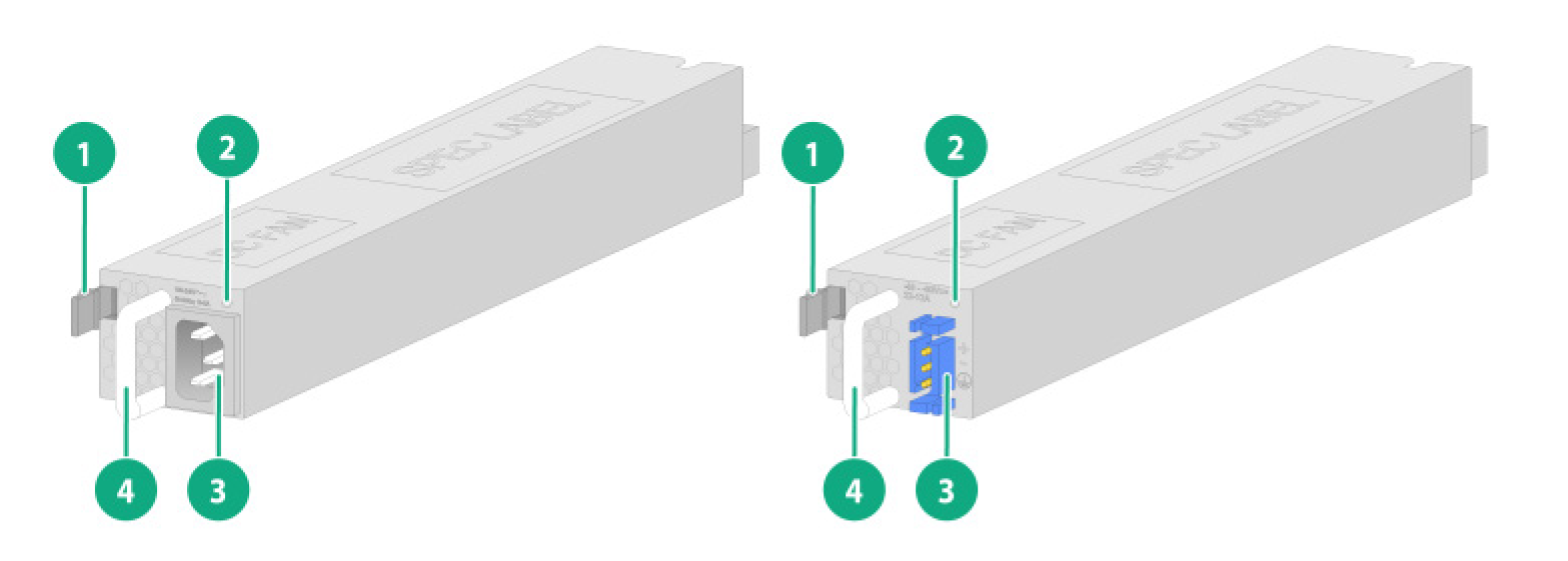
|
(1) Latch |
(2) Status LED |
|
(3) Power input receptacle |
(4) Handle |
Fan trays
Fan tray specifications
Table2-4 Fan tray specifications
|
Fan tray model |
Item |
Specification |
|
LSWM1BFANSCB |
Dimensions (H × W × D) |
80 × 80 × 232.6 mm (3.15 × 3.15 × 9.16 in) |
|
Airflow direction |
Air exhausted from the fan tray faceplate |
|
|
Fan speed |
13300 R.P.M |
|
|
Max airflow |
120 CFM (3.40 m3/min) |
|
|
Operating voltage |
12 V |
|
|
Max power consumption |
57 W |
|
|
Operating temperature |
0°C to 45°C (32°F to 113°F) |
|
|
Operating humidity |
5% RH to 95% RH, noncondensing |
|
|
Storage temperature |
–40°C to +70°C (–40°F to +158°F) |
|
|
Storage humidity |
5% RH to 95% RH, noncondensing |
Fan tray views
Figure2-2 LSWM1BFANSCB
Expansion modules
Expansion module specifications
Table2-5 Expansion module specifications
|
Expansion module model |
Item |
Specification |
|
EWPXM1BSTX80 |
Name |
Hardware acceleration module |
|
Port quantity and types |
· 8 × 1000BASE-T Ethernet ports · 8 × GE SFP fiber ports · 8 × 10GE SFP+ fiber ports · 2 × 40GE QSFP+ fiber ports Note: The 1000BASE-T Ethernet ports and GE SFP fiber ports are combo interfaces. Do not use 10GBASE-R-SFP+ fiber ports and 40GBASE-R-QSFP+ fiber ports simultaneously. |
|
|
Port specifications |
· For detailed information about 1000BASE-T Ethernet ports, see Table3-10. · For information about SFP modules supported by the SFP fiber ports, see Table3-4. · For information about SFP+ modules and cables supported by the SFP+ fiber ports, see Table3-6. · For information about QSFP+ modules and cables supported by the QSFP+ fiber ports, see Table3-8. |
|
|
Power consumption |
82.3W~110.4W |
|
|
Dimensions (H × W × D) |
40.1 × 214 × 274.2 mm (1.58 × 8.43 × 10.80 in) |
|
|
Weight |
1.9kg (4.19 lb) |
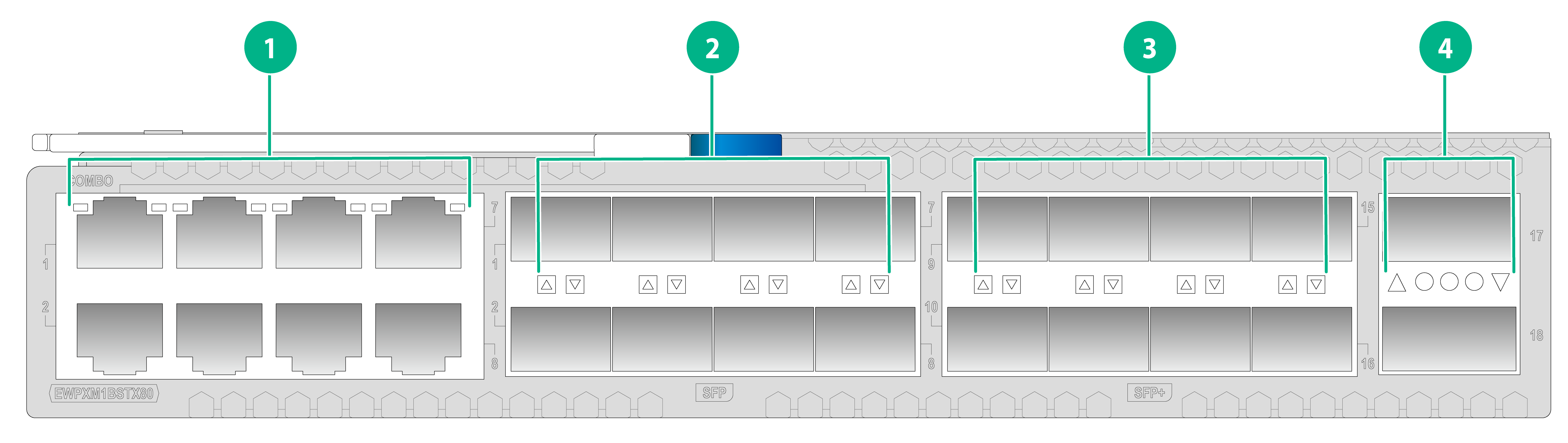
Expansion module views
Figure2-3 Front panel
|
(2) 1000BASE-X-SFP fiber ports |
|
|
(3) 10GBASE-R-SFP+ fiber ports |
(4) 40GBASE-R-QSFP+ fiber ports |
3 Ports and LEDs
Ports
Console port
Table3-1 Console port specifications
|
Item |
Specification |
|
Connector type |
RJ-45 |
|
Compliant standard |
EIA/TIA-232 |
|
Port transmission rate |
9600 bps |
|
Services |
· Provides connection to an ASCII terminal · Provides connection to the serial port of a local PC running terminal emulation program |
|
Compatible models |
WX5860X |
USB port
Table3-2 USB port specifications
|
Item |
Specification |
|
Interface type |
USB 2.0 |
|
Compliant standard |
OHCI |
|
Port transmission rate |
Uploads and downloads data at a rate up to 480 Mbps |
|
Functions and services |
Accesses the file system on the flash of the device, for example, to upload or download application and configuration files |
|
Compatible models |
WX5860X |
|
|
NOTE: USB devices from different vendors vary in compatibilities and drivers. H3C does not guarantee correct operation of USB devices from other vendors on the device. If a USB device fails to operate on the device, replace it with one from another vendor. |
SFP port
Table3-3 SFP port specifications
|
Item |
Specification |
|
Connector type |
LC |
|
Compatible transceiver modules |
GE SFP transceiver modules in Table3-4 |
|
Compatible models |
EWPXM1BSTX80 |
Table3-4 GE SFP transceiver modules
|
Transceiver module type |
Transceiver module model |
Central wavelength |
Receiver sensitivity |
Fiber diameter |
Data rate |
Max transmission distance |
|
GE multi-mode module |
SFP-GE-SX-MM850-A |
850 nm |
–17 dBm |
50 µm |
1.25 Gbps |
550 m (1804.46 ft) |
|
SFP-GE-SX-MM850-D |
850 nm |
–17 dBm |
50 µm |
1.25 Gbps |
550 m (1804.46 ft) |
|
|
GE single-mode module |
SFP-GE-LX-SM1310-A |
1310 nm |
–20 dBm |
9 µm |
1.25 Gbps |
10 km (6.21 miles) |
|
SFP-GE-LX-SM1310-D |
1310 nm |
–20 dBm |
9 µm |
1.25 Gbps |
10 km (6.21 miles) |
|
|
NOTE: · As a best practice, use H3C transceiver modules for the device. · The H3C transceiver modules are subject to change over time. For the most recent list of H3C transceiver modules, contact your H3C Support or marketing staff. · For more information about H3C transceiver modules, see H3C Transceiver Modules User Guide. |
SFP+ port
Table3-5 SFP+ port specifications
|
Item |
Specification |
|
Connector type |
LC |
|
Compatible transceiver modules and cables |
10GE SFP+ transceiver modules and cables in Table3-6 |
|
Compatible devices |
EWPXM1BSTX80 |
Table3-6 10GE SFP+ transceiver modules and cables
|
Transceiver module or cable type |
Transceiver module or cable model |
Central wavelength |
Receiver sensitivity |
Fiber diameter |
Data rate |
Max transmission distance |
|
10GE multi-mode module |
SFP-XG-SX-MM850-A |
850nm |
-9.9dBm |
50µm |
10.31Gb/s |
300m |
|
SFP-XG-SX-MM850-D |
850 nm |
–9.9 dBm |
50 µm |
10.31 Gbps |
300 m (984.25 ft) |
|
|
SFP-XG-SX-MM850-E |
850 nm |
–9.9 dBm |
50 µm |
10.31 Gbps |
300 m (984.25 ft) |
|
|
10GE single-mode module |
SFP-XG-LX-SM1310 |
1310nm |
-14.4dBm |
9µm |
10.31Gb/s |
10km |
|
SFP-XG-LX-SM1310-D |
1310 nm |
–14.4 dBm |
9 µm |
10.31 Gbps |
10 km (6.21 miles) |
|
|
SFP-XG-LX-SM1310-E |
1310 nm |
–14.4 dBm |
9 µm |
10.31 Gbps |
10 km (6.21 miles) |
|
|
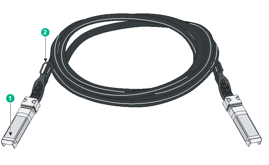
SFP+ cable |
LSWM3STK |
N/A |
N/A |
N/A |
N/A |
3 m (9.84 ft) |
|
(1) Connector |
(2) Pull latch |
|
|
NOTE: · As a best practice, use H3C transceiver modules and cables for the device. · The H3C transceiver modules and cables are subject to change over time. For the most recent list of H3C transceiver modules and cables, contact your H3C Support or marketing staff. · For more information about H3C transceiver modules and cables, see H3C Transceiver Modules User Guide. |
QSFP+ port
Table3-7 QSFP+ port specifications
|
Item |
Specification |
|
Connector type |
· LC: QSFP-40G-LR4L-WDM1300, QSFP-40G-LR4-WDM1300, QSFP-40G-BIDI-SR-MM850 · MPO: QSFP-40G-CSR4-MM850, QSFP-40G-SR4-MM850 |
|
Compatible transceiver modules and cables |
QSFP+ transceiver modules and cables in Table3-8 |
|
Compatible models |
EWPXM1BSTX80 |
Table3-8 QSFP+ transceiver modules and cables
|
Transceiver module or cable type |
Transceiver module or cable model |
Central wavelength |
Receiver sensitivity |
Fiber diameter |
Data rate |
Max transmission distance |
|
QSFP+ 40G transceiver module |
QSFP-40G-BIDI-SR-MM850 |
850 nm |
–6 dBm |
50 µm |
41.25 Gbps |
100 m (328.08 ft) |
|
QSFP-40G-CSR4-MM850 |
850 nm |
–9.9 dBm |
50 µm |
41.25 Gbps |
300 m (984.25 ft) |
|
|
QSFP-40G-SR4-MM850 |
850 nm |
–9.5 dBm |
50 µm |
41.25 Gbps |
100 m (328.08 ft) |
|
|
QSFP-40G-LR4-WDM1300 |
1310 nm |
–11.5 dBm |
9 µm |
41.25 Gbps |
10 km (6.21 miles) |
|
|
QSFP-40G-LR4L-WDM1300 |
1310 nm |
–11.5 dBm |
9 µm |
41.25 Gbps |
2 km (1.24 miles) |
|
|
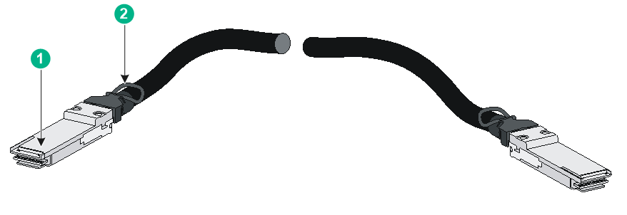
QSFP+ cable |
LSWM1QSTK2 |
N/A |
N/A |
N/A |
N/A |
5 m (16.40 ft) |
Figure3-2 QSFP+ cable
|
(1) Connector |
(2) Pull latch |
|
|
NOTE: · As a best practice, use H3C transceiver modules and cables for the device. · The H3C transceiver modules and cables are subject to change over time. For the most recent list of H3C transceiver modules and cables, contact your H3C Support or marketing staff. · For more information about H3C transceiver modules and cables, see H3C Transceiver Modules User Guide. |
100/1000BASE-T management Ethernet port
Table3-9 100/1000BASE-T management Ethernet port specifications
|
Item |
Specification |
|
Connector type |
RJ-45 |
|
Rate, duplex mode, and auto-MDI/MDI-X |
· 100 Mbps, half/full duplex · 1000 Mbps, full duplex · MDI/MDI-X autosensing |
|
Transmission medium |
Category 5 or above twisted pair cable |
|
Max transmission distance |
100 m (328.08 ft) |
|
Compliant standard |
IEEE 802.3i, 802.3u, 802.3ab |
|
Functions and services |
Device software and Boot ROM upgrade, network management |
|
Compatible models |
WX5860X |
1000BASE-T Ethernet port
Table3-10 1000BASE-T Ethernet port specifications
|
Item |
Specification |
|
Connector type |
RJ-45 |
|
Auto-MDI/MDI-X |
MDI/MDI-X autosensing |
|
Max transmission distance |
100 m (328.08 ft) |
|
Transmission medium |
Category 5 or above twisted pair cable |
|
Compliant standard |
IEEE 802.3ab |
|
Compatible models |
EWPXM1BSTX80 |
Combo interface
The 1000BASE-T Ethernet ports and 1000BASE-X-SFP fiber ports on the EWPXM1BSTX80 expansion module are combo interfaces. Do not use 10GBASE-R-SFP+ fiber ports and 40GBASE-R-QSFP+ fiber ports simultaneously.
LEDs
WX5860X device port status LEDs
System status LED
The system status LED shows the operating status of the device.
Table3-11 System status LED description
|
LED mark |
Status |
Description |
|
SYS |
Fast flashing green (4 Hz) |
The system is starting up. |
|
Slow flashing green (0.5 Hz) |
The system is operating correctly. |
|
|
Steady red |
A critical alarm has been triggered, for example, power supply alarm, fan tray alarm, high temperature alarm, and software loss. |
|
|
Off |
The device has not started up. |
100/1000BASE-T management Ethernet port LED
Table3-12 100/1000BASE-T management Ethernet port LED description
|
LED mark |
Status |
Description |
|
LINK/ACT |
Steady green |
A link is present. |
|
Flashing green |
The port is receiving or sending data. |
|
|
Off |
No link is present. |
Power supply status LED
Table3-13 Power supply status LED description
|
LED status |
Description |
|
Steady green |
The power supply is operating correctly. |
|
Flashing green |
The power supply has power input but is not installed on the device. |
|
Steady red |
The power supply is faulty or has entered protection state. |
|
Red/green flashing alternatively |
The power supply has generated an alarm for power issues (such as output overcurrent, output overload, and overtemperature), but has not entered protection state. |
|
Flashing red |
· The power supply does not have power input. The device is installed with two power supplies. If one has power input, but the other does not, the status LED on the power supply that does not have power input flashes red. · The power supply has entered input undervoltage protection state. |
|
Off |
The power supply does not have power input. |
Status LED on a fan tray
The LSWM1BFANSCB fan tray provides a status LED to indicate its operating status.
Table3-14 Description for the status LED on a fan tray
|
LED status |
Description |
|
On |
The fan tray is operating incorrectly. |
|
Off |
The fan tray is operating correctly. |
Port LED on an expansion module
Table3-15 Description for port LEDs on an expansion module
|
LED |
Status |
Description |
|
1000BASE-T Ethernet port LED |
Steady green |
A 1000 Mbps link is present on the port. |
|
Flashing green |
The port is receiving or sending data at 1000 Mbps. |
|
|
Off |
No link is present on the port. |
|
|
SFP fiber port LED |
Steady green |
A 1000 Mbps link is present on the port. |
|
Flashing green |
The port is receiving or sending data at 1000 Mbps. |
|
|
Off |
No link is present on the port. |
|
|
10G SFP+ port LED |
Steady green |
A 10 Gbps link is present on the port. |
|
Flashing green |
The port is receiving or sending data at 10 Gbps. |
|
|
Off |
No link is present on the port. |
|
|
40G QSFP+ port LED |
Steady green |
A 40 Gbps link is present on the port. |
|
Flashing green |
The port is receiving or sending data at 40 Gbps. |
|
|
Off |
No link is present on the port. |
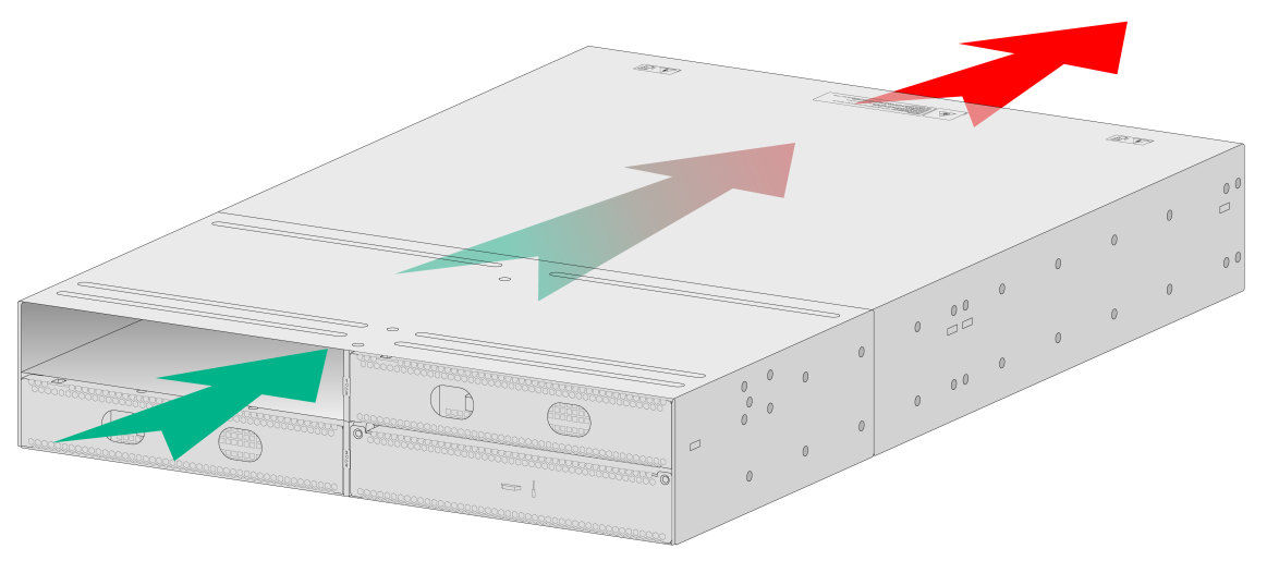
4 Cooling system
To dissipate heat timely and enhance system stability, the device uses a high-performance cooling system. Consider the site ventilation design when you plan the installation site for the device.
Table4-1 Cooling system
|
Product series |
Product model |
Airflow direction |
|
WX5800X series |
WX5860X |
The device uses a front-rear air aisle. It can provide airflow from the port side to the power supply side by using fan trays. See Figure4-1. |
Figure4-1 Airflow from the port side to the power supply side through the device chassis