- Table of Contents
- Related Documents
-
| Title | Size | Download |
|---|---|---|
| 02-Removable Components | 3.29 MB |
Contents
2 Removable components
Routing and switching units
The routing and switching unit (RSU) is the core component of the router. It runs the system software and saves system configuration information. It delivers the following functions:
· Protocol processing
· Data packet forwarding
· Interface control
· Fault detection
RSU-300
View
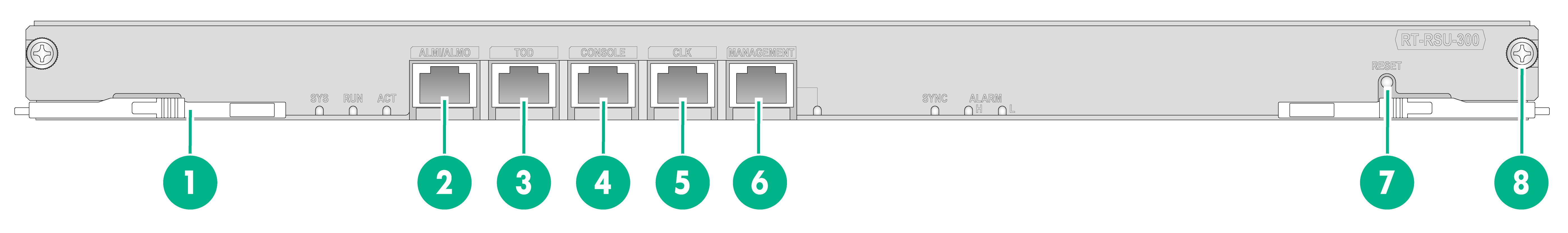
Figure2-1 RSU-300 view
|
(1) Ejector lever |
(2) ALMI/ALMO port |
(3) ToD port |
|
(4) Console port (CONSOLE) |
(5) CLK port |
(6) Management Ethernet port |
|
(7) Reset button (RESET) |
(8) Captive screw |
|
LEDs
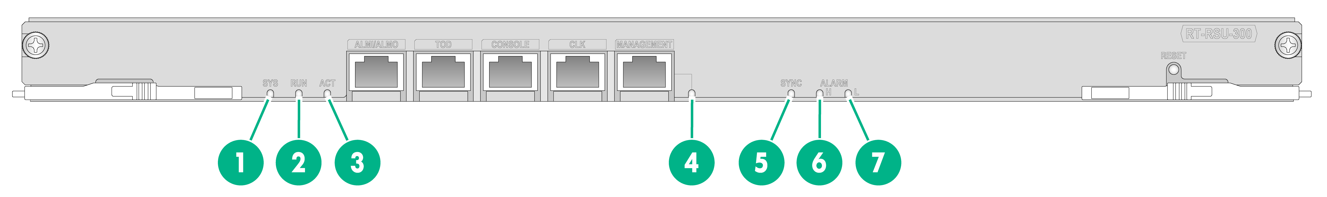
Figure2-2 RSU-300 LEDs
|
(1) System status LED (SYS) |
(2) Running status LED (RUN) |
(3) Active/standby status LED (ACT) |
|
|
(4) Management Ethernet port LED (MANAGEMENT) |
(5) Clock synchronization LED (SYNC) |
||
|
(6) High severity alarm LED (ALARM H) |
(7) Low severity alarm LED (ALARM L) |
||
Table2-1 LED description
|
LED |
Status |
Description |
|
SYS |
Flashing green (eight times per second) |
· BIOS stage—BIOS is starting up. · BootWare stage—The system software image is being decompressed. |
|
Flashing yellow (once per second) |
· BIOS stage—The memory does not exist or system initialization has failed. · BootWare stage—The SDRAM has failed the POST. |
|
|
Flashing yellow (eight times per second) |
The extended segment does not exist (BIOS stage). |
|
|
Steady green |
· BootWare stage—The SDRAM is being tested. · Comware stage—The kernel is starting up. |
|
|
Flashing green (once per second) |
The Comware system is starting up or is operating correctly (Comware stage). |
|
|
Steady yellow |
The boot.bin file does not exist (BootWare stage). |
|
|
Off |
A system hardware failure has occurred. |
|
|
RUN |
Flashing green (once per second) |
BIOS has started up and BootWare is starting up. |
|
Flashing red (once per second) |
BIOS is starting up. |
|
|
Steady green |
The Comware system is starting up or is operating correctly. |
|
|
Off |
No power is present. |
|
|
ACT |
Steady green |
The RSU is in active mode. |
|
Flashing green (eight times per second) |
The RSUs are establishing active and standby roles. |
|
|
Off |
The RSU is in standby mode. |
|
|
MANAGEMENT |
Steady green |
A 100 Mbps link is present on the port. |
|
Flashing green |
The port is sending or receiving data at 100 Mbps. |
|
|
Off |
No link is present on the port. |
|
|
SYNC |
Steady green |
The system clock is in free running mode and no clock source priority list is configured for the system clock. |
|
Steady yellow |
The system clock is tracing a clock source in the clock source priority list. |
|
|
Off |
The system clock is in time synchronization mode, and the PTP clock and system clock are tracing clock sources. |
|
|
ALARM H |
Steady red |
A high severity alarm has occurred on the router. |
|
Off |
No high severity alarm has occurred on the router. |
|
|
ALARM L |
Steady yellow |
A low severity alarm has occurred on the router. |
|
Off |
No low severity alarm has occurred on the router. |
Ports
Table2-2 Port specifications
|
Port |
Specification |
|
Console port |
1 |
|
Management Ethernet port |
1 |
|
ALMI/ALMO port |
1 |
|
ToD port |
1 |
|
CLK port |
1 |
|
Reset button |
1 |
|
DIAG button |
N/A |
Technical specifications
Table2-3 Technical specifications
|
Item |
Specification |
|
Net weight |
2.0 kg (4.41 lb) |
|
Dimensions (H × W × D) |
25 × 382 × 208 mm (0.98 × 15.04 × 8.19 in) |
|
Memory |
8 GB DDR4 |
|
Flash |
4 GB |
RSU-400
View
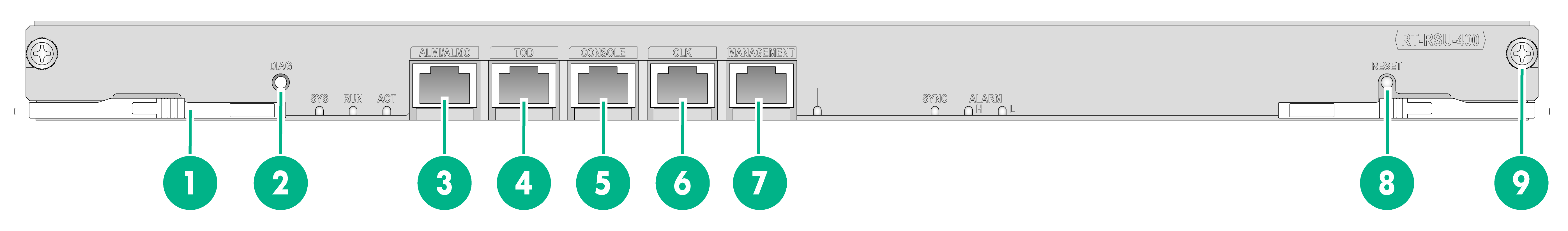
Figure2-3 RSU-400 view
|
(1) Ejector lever |
(2) Diagnostic button (DIAG) |
(3) ALMI/ALMO port |
|
(4) ToD port |
(5) Console port (CONSOLE) |
(6) CLK port |
|
(7) Management Ethernet port |
(8) Reset button (RESET) |
(9) Captive screw |
LEDs
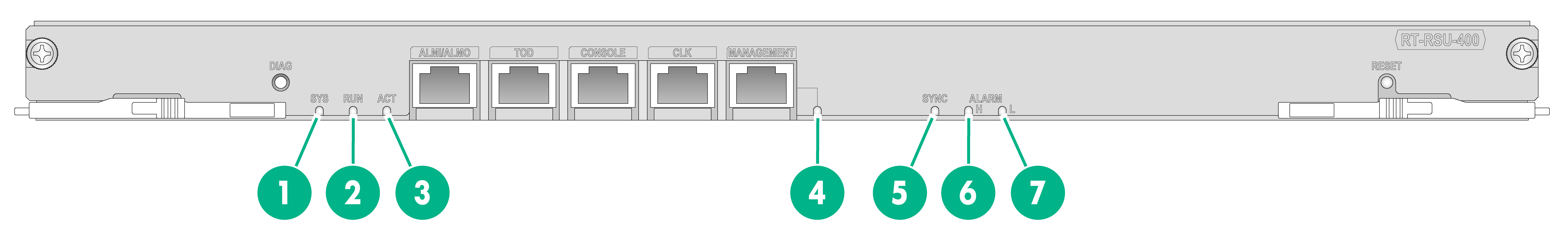
Figure2-4 RSU-400 LEDs
|
(1) System status LED (SYS) |
(2) Running status LED (RUN) |
(3) Active/standby status LED (ACT) |
|
|
(4) Management Ethernet port LED (MANAGEMENT) |
(5) Clock synchronization LED (SYNC) |
||
|
(6) High severity alarm LED (ALARM H) |
(7) Low severity alarm LED (ALARM L) |
||
Table2-4 LED description
|
LED |
Status |
Description |
|
SYS |
Flashing green (eight times per second) |
· BIOS stage—BIOS is starting up. · BootWare stage—The system software image is being decompressed. |
|
Flashing yellow (once per second) |
· BIOS stage—The memory does not exist or system initialization has failed. · BootWare stage—The SDRAM has failed the POST. |
|
|
Flashing yellow (eight times per second) |
The extended segment does not exist (BIOS stage). |
|
|
Steady green |
· BootWare stage—The SDRAM is being tested. · Comware stage—The kernel is starting up. |
|
|
Flashing green (once per second) |
The Comware system is starting up or is operating correctly (Comware stage). |
|
|
Steady yellow |
The boot.bin file does not exist (BootWare stage). |
|
|
Off |
A system hardware failure has occurred. |
|
|
RUN |
Flashing green (eight times per second) |
The RSU is collecting diagnostic information. |
|
Flashing green (once per second) |
BIOS has started up and BootWare is starting up. |
|
|
Flashing red (once per second) |
BIOS is starting up. |
|
|
Steady green |
The Comware system is starting up or is operating correctly. |
|
|
Off |
No power is present. |
|
|
ACT |
Steady green |
The RSU is in active mode. |
|
Flashing green (eight times per second) |
The RSUs are establishing active and standby roles. |
|
|
Off |
The RSU is in standby mode. |
|
|
MANAGEMENT |
Steady green |
A 100 Mbps link is present on the port. |
|
Flashing green |
The port is sending or receiving data at 100 Mbps. |
|
|
Off |
No link is present on the port. |
|
|
SYNC |
Steady green |
· The system clock is in free running mode and no clock source priority list is configured for the system clock. · The system clock is tracing a clock source in the clock source priority list. · The system clock is in time synchronization mode, and the PTP clock and system clock are tracing clock sources. |
|
Steady yellow |
· All the clock sources except for the internal source have been lost, and system clock works in holdover or free running mode. · The system clock is in time synchronization mode but no clock source is available. The system clock and PTP clock are in holdover or free running mode. |
|
|
Off |
The system is not powered on, or synchronization is not performed during the startup process of the module. |
|
|
ALARM H |
Steady red |
A high severity alarm has occurred on the router. |
|
Off |
No high severity alarm has occurred on the router. |
|
|
ALARM L |
Steady yellow |
A low severity alarm has occurred on the router. |
|
Off |
No low severity alarm has occurred on the router. |
Ports
Table2-5 Port specifications
|
Port |
Specification |
|
Console port |
1 |
|
Management Ethernet port |
1 |
|
ALMI/ALMO port |
1 |
|
ToD port |
1 |
|
CLK port |
1 |
|
Reset button |
1 |
|
DIAG button |
1 |
|
|
NOTE: · Do not install RSUs of different models on the same router. · To avoid clock synchronization exceptions, use a shielded cable to connect the ToD port on the RSU. · Use the DIAG button to quickly collect diagnostic information for troubleshooting. To enable the diagnostics feature, press and hold the DIAG button for more than 0.5 seconds. Fault collection is complete if the RUN LED on the RSU changes from fast flashing to steady on. To view the generated compressed diag file, execute the dir command. |
Technical specifications
Table2-6 Technical specifications
|
Item |
Specification |
|
Net weight |
2.0 kg (4.41 lb) |
|
Dimensions (H × W × D) |
25 × 382 × 208 mm (0.98 × 15.04 × 8.19 in) |
|
Memory |
8 GB DDR4 |
|
Flash |
4 GB |
RSU-400S
View
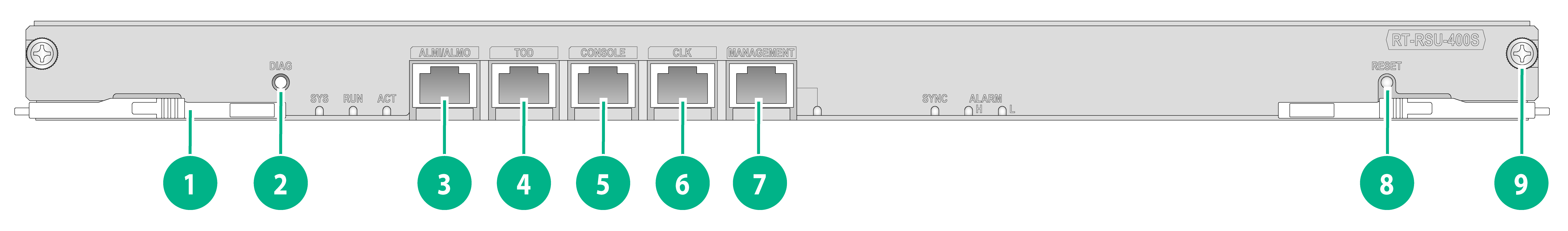
Figure2-5 RSU-400S view
|
(1) Ejector lever |
(2) Diagnostic button (DIAG) |
(3) ALMI/ALMO port |
|
(4) ToD port |
(5) Console port (CONSOLE) |
(6) CLK port |
|
(7) Management Ethernet port |
(8) Reset button (RESET) |
(9) Captive screw |
LEDs
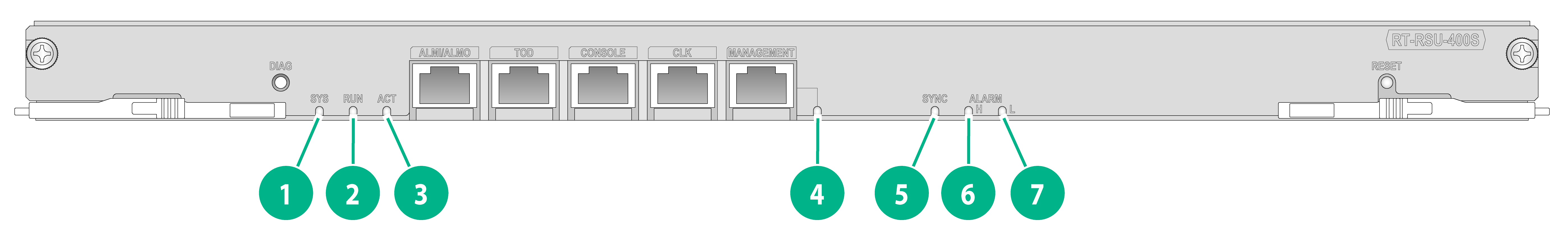
Figure2-6 RSU-400S LEDs
|
(1) System status LED (SYS) |
(2) Running status LED (RUN) |
(3) Active/standby status LED (ACT) |
|
|
(4) Management Ethernet port LED (MANAGEMENT) |
(5) Clock synchronization LED (SYNC) |
||
|
(6) High severity alarm LED (ALARM H) |
(7) Low severity alarm LED (ALARM L) |
||
Table2-7 LED description
|
LED |
Status |
Description |
|
SYS |
Flashing green (eight times per second) |
· BIOS stage—BIOS is starting up. · BootWare stage—The system software image is being decompressed. |
|
Flashing yellow (once per second) |
· BIOS stage—The memory does not exist or system initialization has failed. · BootWare stage—The SDRAM has failed the POST. |
|
|
Flashing yellow (eight times per second) |
The extended segment does not exist (BIOS stage). |
|
|
Steady green |
· BootWare stage—The SDRAM is being tested. · Comware stage—The kernel is starting up. |
|
|
Flashing green (once per second) |
The Comware system is starting up or is operating correctly (Comware stage). |
|
|
Steady yellow |
The boot.bin file does not exist (BootWare stage). |
|
|
Off |
A system hardware failure has occurred. |
|
|
RUN |
Flashing green (eight times per second) |
The RSU is collecting diagnostic information. |
|
Flashing green (once per second) |
BIOS has started up and BootWare is starting up. |
|
|
Flashing red (once per second) |
BIOS is starting up. |
|
|
Steady green |
The Comware system is starting up or is operating correctly. |
|
|
Off |
No power is present. |
|
|
ACT |
Steady green |
The RSU is in active mode. |
|
Flashing green (eight times per second) |
The RSUs are establishing active and standby roles. |
|
|
Off |
The RSU is in standby mode. |
|
|
MANAGEMENT |
Steady green |
A 100 Mbps link is present on the port. |
|
Flashing green |
The port is sending or receiving data at 100 Mbps. |
|
|
Off |
No link is present on the port. |
|
|
SYNC |
Steady green |
· The system clock is in free running mode and no clock source priority list is configured for the system clock. · The system clock is tracing a clock source in the clock source priority list. · The system clock is in time synchronization mode, and the PTP clock and system clock are tracing clock sources. |
|
Steady yellow |
· All the clock sources except for the internal source have been lost, and system clock works in holdover or free running mode. · The system clock is in time synchronization mode but no clock source is available. The system clock and PTP clock are in holdover or free running mode. |
|
|
Off |
The system is not powered on, or synchronization is not performed during the startup process of the module. |
|
|
ALARM H |
Steady red |
A high severity alarm has occurred on the router. |
|
Off |
No high severity alarm has occurred on the router. |
|
|
ALARM L |
Steady yellow |
A low severity alarm has occurred on the router. |
|
Off |
No low severity alarm has occurred on the router. |
Ports
Table2-8 Port specifications
|
Port |
Specification |
|
Console port |
1 |
|
Management Ethernet port |
1 |
|
ALMI/ALMO port |
1 |
|
ToD port |
1 |
|
CLK port |
1 |
|
Reset button |
1 |
|
DIAG button |
1 |
|
|
NOTE: · Do not install RSUs of different models on the same router. · To avoid clock synchronization exceptions, use a shielded cable to connect the ToD port on the RSU. · Use the DIAG button to quickly collect diagnostic information for troubleshooting. To enable the diagnostics feature, press and hold the DIAG button for more than 0.5 seconds. Fault collection is complete after the RUN LED on the RSU changes from fast flashing to steady on. To view the generated compressed diag file, execute the dir command. |
Technical specifications
Table2-9 Technical specifications
|
Item |
Specification |
|
Net weight |
2.0 kg (4.41 lb) |
|
Dimensions (H × W × D) |
25 × 382 × 208 mm (0.98 × 15.04 × 8.19 in) |
|
Memory |
8 GB DDR4 |
|
Flash |
4 GB |
RSU-400-G
View
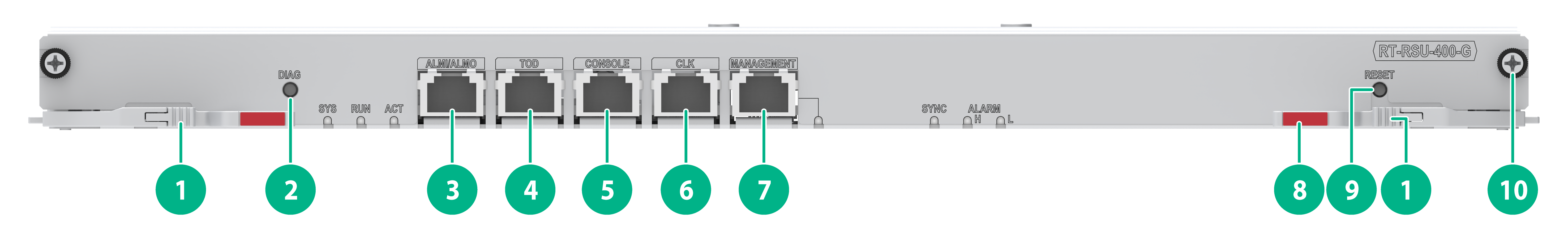
Figure2-7 RSU-400-G view
|
(1) Micro switch |
(2) Diagnostic button (DIAG) |
(3) ALMI/ALMO port |
|
(4) ToD port |
(5) Console port (CONSOLE) |
(6) CLK port |
|
(7) Management Ethernet port |
(8) Ejector lever |
(9) Reset button (RESET) |
|
(10) Captive screw |
||
LEDs
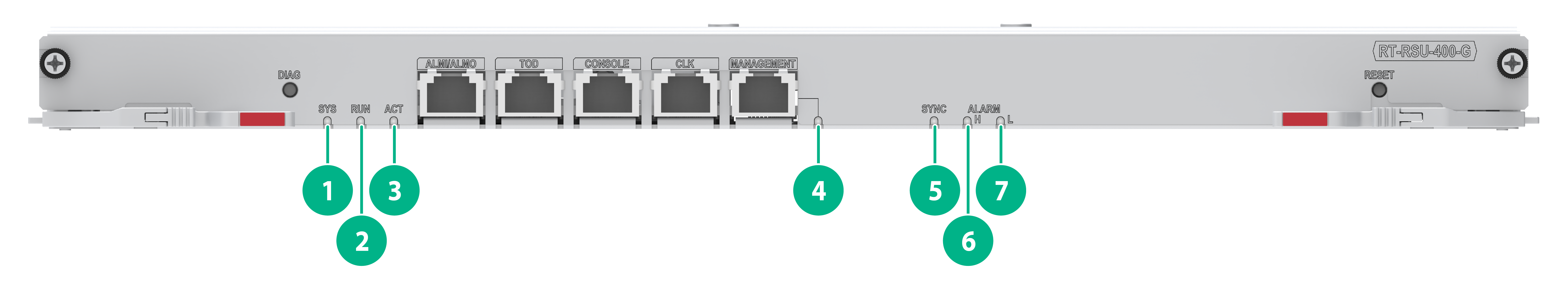
Figure2-8 RSU-400-G LEDs
|
(1) System status LED (SYS) |
(2) Running status LED (RUN) |
(3) Active/standby status LED (ACT) |
|
(4) Management Ethernet port LED (MANAGEMENT) |
(5) Clock synchronization LED (SYNC) |
(6) High severity alarm LED (ALARM H) |
|
(7) Low severity alarm LED (ALARM L) |
||
Table2-10 LED description
|
LED |
Status |
Description |
|
SYS |
Flashing green (eight times per second) |
The system is in BootWare stage. |
|
Flashing yellow (once per second) |
The memory does not exist or system initialization has failed (BootWare stage). |
|
|
Flashing yellow (eight times per second) |
The extended segment does not exist (BootWare stage). |
|
|
Steady green |
The kernel (including Eshell) is starting up. |
|
|
Flashing green (once per second) |
The Comware system is starting up or is operating correctly (Comware stage). |
|
|
Steady yellow |
The boot.bin file does not exist (BootWare stage). |
|
|
Off |
A system hardware failure has occurred. |
|
|
RUN |
Flashing green (eight times per second) |
The RSU is collecting diagnostic information. |
|
Flashing green (once per second) |
BootWare is starting up. |
|
|
Steady green |
The Comware system is starting up or is operating correctly. |
|
|
Off |
No power is present. |
|
|
ACT |
Steady green |
The RSU is in active mode. |
|
Flashing green (eight times per second) |
The RSUs are establishing active and standby roles. |
|
|
Off |
The RSU is in standby mode. |
|
|
MANAGEMENT |
Steady green |
A 1000 Mbps link is present on the port. |
|
Flashing green |
The port is sending or receiving data at 1000 Mbps. |
|
|
Steady yellow |
A 100 Mbps link is present on the port. |
|
|
Flashing yellow |
The port is sending or receiving data at 100 Mbps. |
|
|
Off |
No link is present on the port. |
|
|
SYNC |
Steady green |
· The system clock is in free running mode and no clock source priority list is configured for the system clock. · The system clock is tracing a clock source in the clock source priority list. · The system clock is in time synchronization mode, and the PTP clock and system clock are tracing clock sources. |
|
Steady yellow |
· All the clock sources except for the internal source have been lost, and system clock works in holdover or free running mode. · The system clock is in time synchronization mode but no clock source is available. The system clock and PTP clock are in holdover or free running mode. |
|
|
Off |
The system is not powered on, or synchronization is not performed during the startup process of the module. |
|
|
ALARM H |
Steady red |
A high severity alarm has occurred on the router. |
|
Off |
No high severity alarm has occurred on the router. |
|
|
ALARM L |
Steady yellow |
A low severity alarm has occurred on the router. |
|
Off |
No low severity alarm has occurred on the router. |
Ports
Table2-11 Port specifications
|
Port |
Specification |
|
Console port |
1 |
|
Management Ethernet port |
1 |
|
ALMI/ALMO port |
1 |
|
ToD port |
1 |
|
CLK port |
1 |
|
Reset button |
1 |
|
DIAG button |
1 |
|
|
NOTE: · Do not install RSUs of different models on the same router. · To avoid clock synchronization exceptions, use a shielded cable to connect the ToD port on the RSU. · Use the DIAG button to quickly collect diagnostic information for troubleshooting. To enable the diagnostics feature, press and hold the DIAG button for more than 0.5 seconds. Fault collection is complete after the RUN LED on the RSU changes from fast flashing to steady on. To view the generated compressed diag file, execute the dir command. |
Technical specifications
Table2-12 Technical specifications
|
Item |
Specification |
|
Net weight |
1.95 kg (4.30 lb) |
|
Dimensions (H × W × D) |
25 × 382 × 208 mm (0.98 × 15.04 × 8.19 in) |
|
Memory |
8 GB DDR4 |
|
Flash |
8 GB |
Compatibility information
Table2-13 Compatibility matrix between RSUs and routers
|
RSU model |
RA5300 |
RA5300-X |
RA5300-AC |
|
RSU-300 |
√ |
√ |
× |
|
RSU-400 |
√ |
√ |
√ |
|
RSU-400S |
√ |
√ |
√ |
|
RSU-400-G |
√ |
√ |
√ |
Interface modules
Weights and dimensions
Table2-14 Weights and dimensions
|
Interface module model |
Net weight |
Dimensions (H × W × D) |
|
HRIC-CLGQ2 |
0.35 kg (0.77 lb) |
20 × 188 × 208 mm (0.79 × 7.40 × 8.19 in) |
|
HRIC-CQ1F |
0.7 kg (1.54 lb) |
20 × 188 × 208 mm (0.79 × 7.40 × 8.19 in) |
|
HRIC-LGQ2F |
0.7 kg (1.54 lb) |
20 × 188 × 208 mm (0.79 × 7.40 × 8.19 in) |
|
HRIC-LGQ1 |
0.35 kg (0.77 lb) |
20 × 188 × 208 mm (0.79 × 7.40 × 8.19 in) |
|
HRIC-YGS4 |
0.35 kg (0.77 lb) |
20 × 188 × 208 mm (0.79 × 7.40 × 8.19 in) |
|
HRIC-YGS2 |
0.35 kg (0.77 lb) |
20 × 188 × 208 mm (0.79 × 7.40 × 8.19 in) |
|
HRIC-XP8 |
0.35 kg (0.77 lb) |
20 × 188 × 208 mm (0.79 × 7.40 × 8.19 in) |
|
HRIC-XP8-H |
0.75 kg (1.65 lb) |
20 × 188 × 208 mm (0.79 × 7.40 × 8.19 in) |
|
HRIC-XP4 |
0.35 kg (0.77 lb) |
20 × 188 × 208 mm (0.79 × 7.40 × 8.19 in) |
|
HRIC-XP10-G |
0.7 kg (1.54 lb) |
20 × 188 × 208 mm (0.79 × 7.40 × 8.19 in) |
|
HRIC-GP8 |
0.35 kg (0.77 lb) |
20 × 188 × 208 mm (0.79 × 7.40 × 8.19 in) |
|
HRIC-GT8 |
0.35 kg (0.77 lb) |
20 × 188 × 208 mm (0.79 × 7.40 × 8.19 in) |
|
HRIC-GT8-G |
0.6 kg (1.32 lb) |
20 × 188 × 208 mm (0.79 × 7.40 × 8.19 in) |
|
HRIC-GP10-G |
0.65 kg (1.43 lb) |
20 × 188 × 208 mm (0.79 × 7.40 × 8.19 in) |
|
HRIC-ET16-G |
0.65 kg (1.43 lb) |
20 × 188 × 208 mm (0.79 × 7.40 × 8.19 in) |
|
|
NOTE: Module dimensions are expressed in the Height (H) × Width (W) × Depth (D) format: · H—Height of the front panel of the module. · W—Width of the front panel of the module. · D—Depth from the front panel of the module to the connector ends. (The depth includes the connectors and excludes the ejector levers and captive screws). |
Interface modules
The router supports HRIC interface modules. For more information of the HRIC interface modules, see H3C RA5300[5300-X][5300-AC] Routers Interface Module Guide.
Power supplies
PSR1000-54A
View
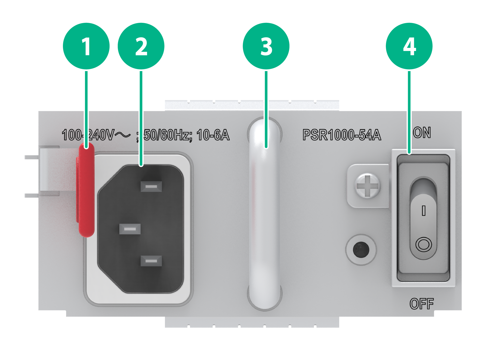
Figure2-9 PSR1000-54A AC power supply view
|
(1) Latch |
(2) AC power receptacle |
|
(3) Handle |
(4) Power switch |
LEDs
Figure2-10 PSR1000-54A AC power supply LEDs

|
(1) Status LED |
Table2-15 LED description
|
LED |
Status |
Description |
|
PWR |
Steady green |
The power supply is operating correctly. |
|
Flashing green |
The power supply has normal power input but has not been turned on. |
|
|
Steady red |
The power supply has failed or has entered a protection state. |
|
|
Alternating between red and green |
An alarm has occurred when one of the following conditions exists on the power supply but the power supply does not enter protection state: · Output overcurrent. · Output overvoltage. · Overtemperature. |
|
|
Off |
This power supply does not have power input, or the power supply has power input but has not been turned on. |
Technical specifications
Table2-16 Technical specifications
|
Item |
Specification |
|
Net weight |
0.87 kg (1.92 lb) |
|
Dimensions (H × W × D) |
38.7 × 79.5 × 185 mm (1.52 × 3.13 × 7.28 in) |
|
Rated input voltage range |
· 100 to 127 VAC (dual live wires) @ 50 or 60 Hz · 200 to 240 VAC @ 50 or 60 Hz · 240 VDC |
|
Max input current |
10 A |
|
Max power |
1000 W |
PWR-RA5300-D
View
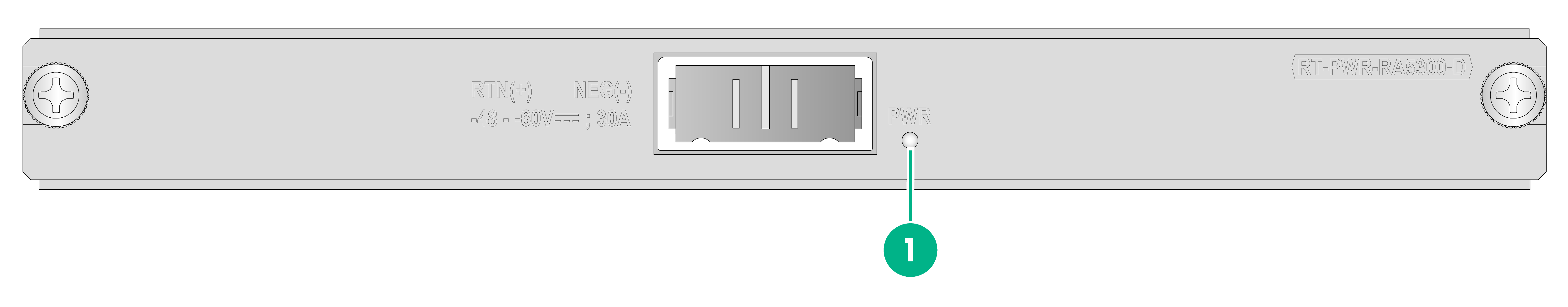
Figure2-11 PWR-RA5300-D DC power supply view

|
(1) DC power receptacle |
(2) Captive screw |
LEDs
Figure2-12 PWR-RA5300-D DC power supply LEDs
|
(1) Status LED (PWR) |
Table2-17 LED description
|
LED |
Status |
Description |
|
PWR |
Steady green |
The power supply is operating correctly. |
|
Off |
No power is present. |
Technical specifications
Table2-18 Technical specifications
|
Item |
Specification |
|
Net weight |
0.5 kg (1.10 lb) |
|
Dimensions (H × W × D) |
20 × 188 × 205 mm (0.79 × 7.40 × 8.07 in) |
|
Rated input voltage range |
–48 to –60 VDC |
|
Max input current |
30 A |
DC power cord specifications
DC power cords are used for connecting the DC power supplies of a router to the external DC power supply system.
See Table2-19 for the DC power cords supported by the PWR-RA5300-D DC power supply available for the RA5300 and RA5300-X routers.
Table2-19 DC power cord specifications
|
BOM No. |
Length |
|
0404A17M |
5 m (16.40 ft) |
Compatibility information
Table2-20 Compatibility matrix between power supplies and routers
|
Power supply model |
RA5300 |
RA5300-X |
RA5300-AC |
|
PSR1000-54A |
× |
× |
√ |
|
PWR-RA5300-D |
√ |
√ |
× |
Fan trays
FAN-60-6-A
View
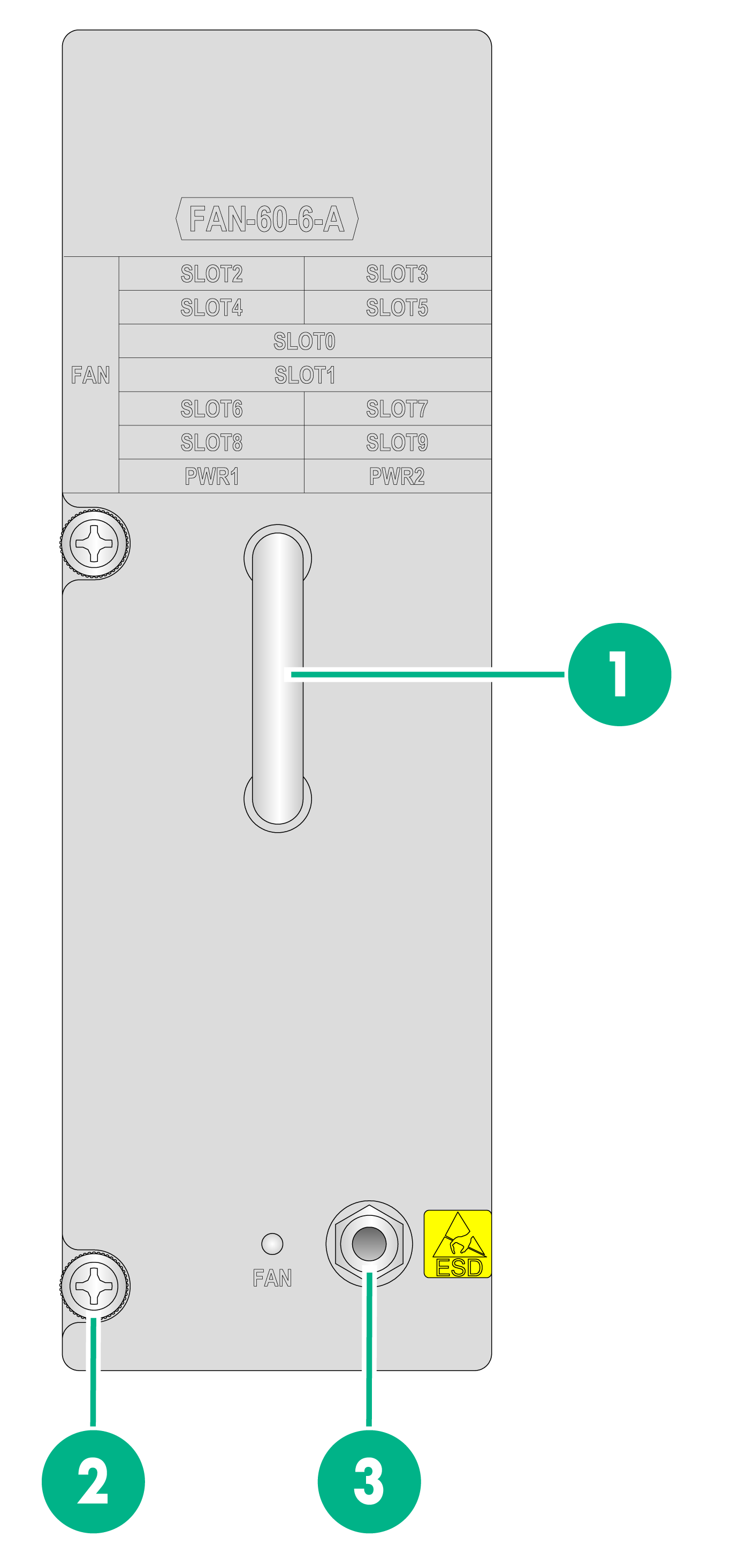
Figure2-13 FAN-60-6-A fan tray view
|
(1) Handle |
(2) Captive screw |
(3) ESD jack |
LEDs
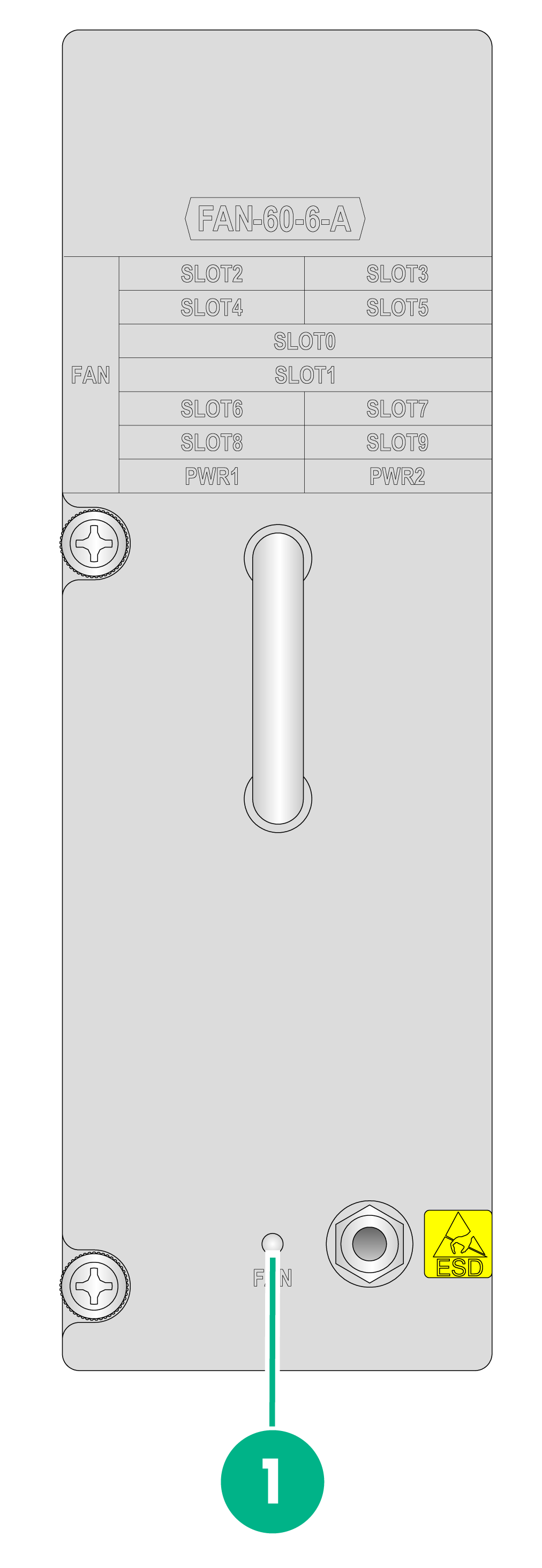
Figure2-14 FAN-60-6-A fan tray LEDs
|
(1) Fan tray status LED (FAN) |
Table2-21 LED description
|
LED |
Status |
Descriptions |
|
FAN |
Steady green |
The fan tray is operating correctly. |
|
Steady red |
The fan tray has failed. |
|
|
Off |
No power is present on the fan tray, or the fan tray is not in place. |
Technical specifications
Table2-22 Technical specifications
|
Item |
Specification |
|
Net weight |
1.3 kg (2.87 lb) |
|
Dimensions (H × W × D) |
51 × 158 × 239 mm (2.01 × 6.22 × 9.41 in), including the handle |
|
Number of fans |
6 (support for automatic speed adjustment) |
|
Hot swapping |
Supported |
FAN-60-6-B
View
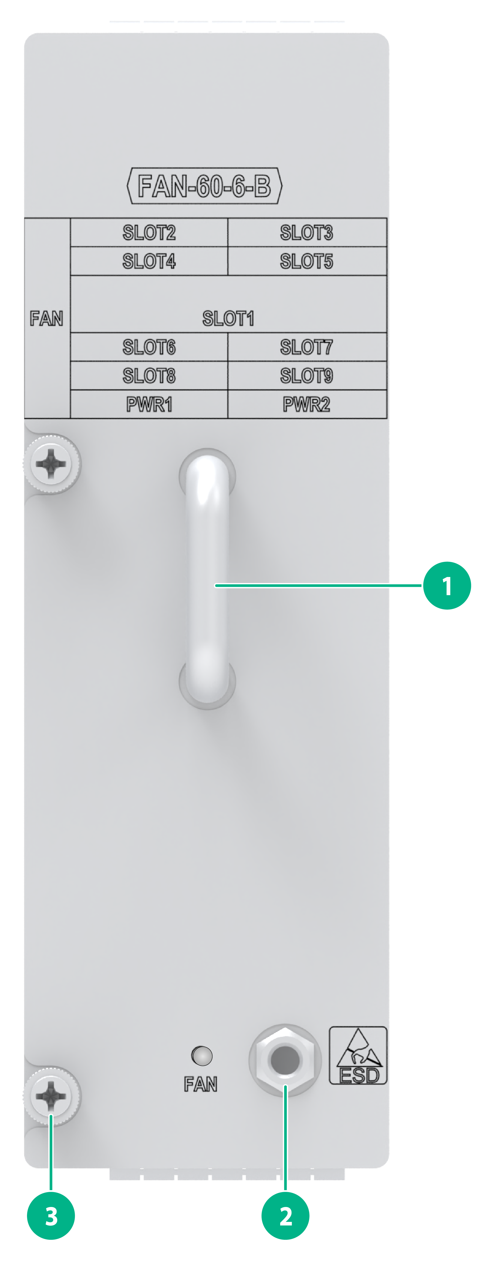
Figure2-15 FAN-60-6-B fan tray view
|
(1) Handle |
(2) ESD jack |
(3) Captive screw |
LEDs
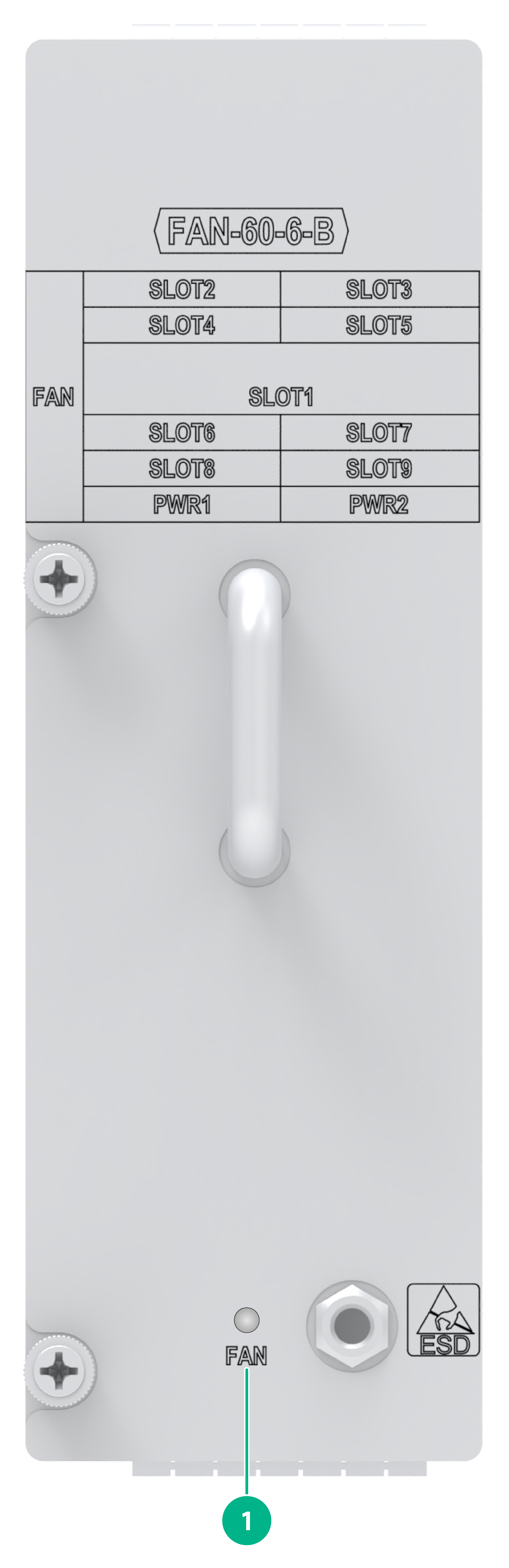
Figure2-16 FAN-60-6-B fan tray LEDs
|
(1) Fan tray status LED (FAN) |
Table2-23 LED description
|
LED |
Status |
Descriptions |
|
FAN |
Steady green |
The fan tray is operating correctly. |
|
Steady red |
The fan tray has failed. |
|
|
Off |
No power is present on the fan tray, or the fan tray is not in place. |
Technical specifications
Table2-24 Technical specifications
|
Item |
Specification |
|
Net weight |
1.2 kg (2.65 lb) |
|
Dimensions (H × W × D) |
51 × 158 × 239 mm (2.01 × 6.22 × 9.41 in), including the handle |
|
Number of fans |
6 (support for automatic speed adjustment) |
|
Hot swapping |
Supported |
FAN-60-6-C
View
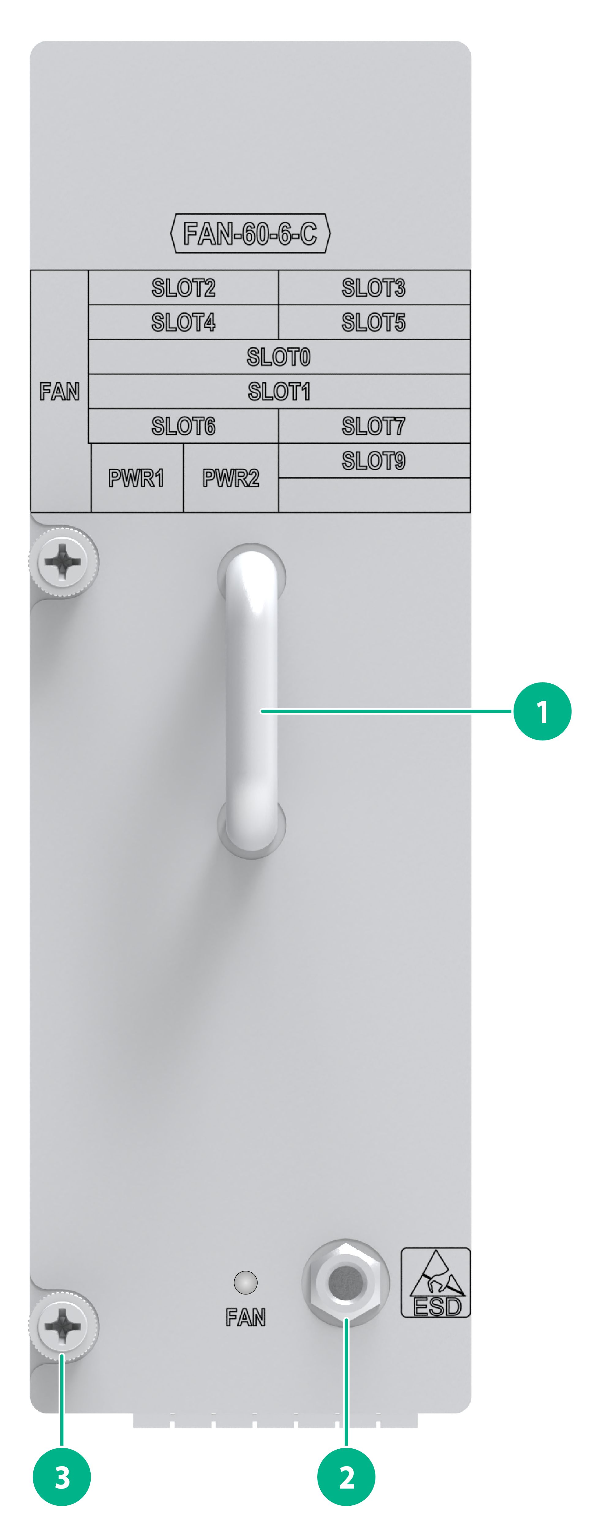
Figure2-17 FAN-60-6-C fan tray view
|
(1) Handle |
(2) ESD jack |
(3) Captive screw |
LEDs
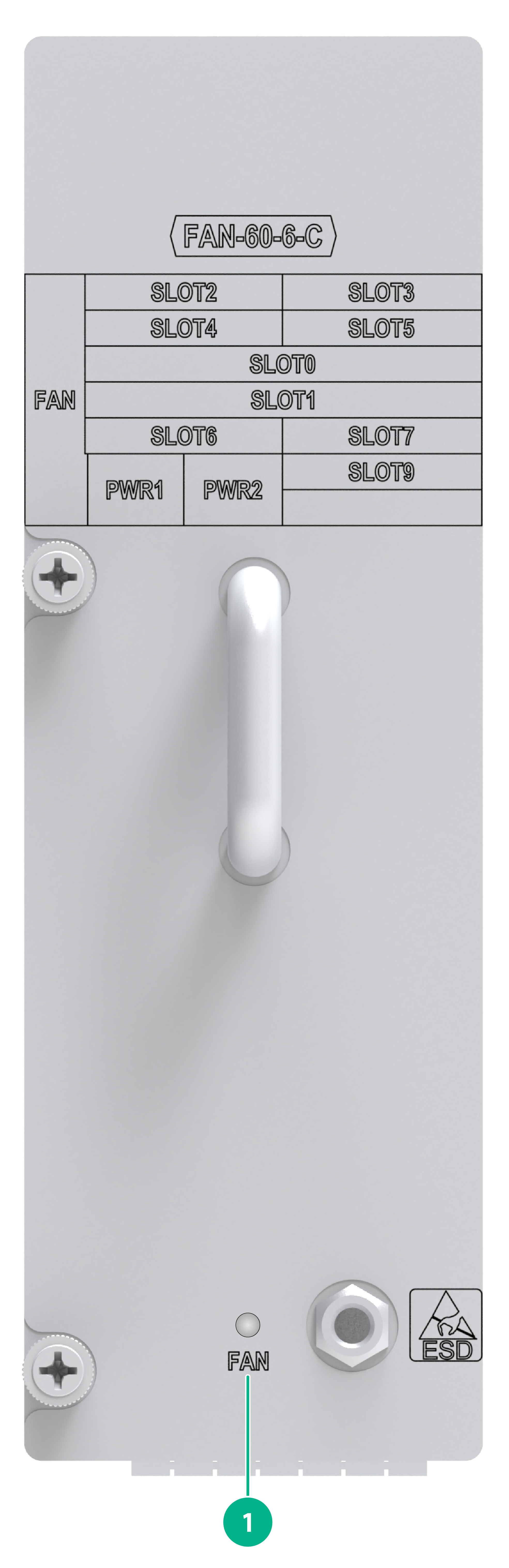
Figure2-18 FAN-60-6-C fan tray LEDs
|
(1) Fan tray status LED (FAN) |
Table2-25 LED description
|
LED |
Status |
Descriptions |
|
FAN |
Steady green |
The fan tray is operating correctly. |
|
Steady red |
The fan tray has failed. |
|
|
Off |
No power is present on the fan tray, or the fan tray is not in place. |
Technical specifications
Table2-26 Technical specifications
|
Item |
Specification |
|
Net weight |
1.2 kg (2.65 lb) |
|
Dimensions (H × W × D) |
51 × 158 × 239 mm (2.01 × 6.22 × 9.41 in), including the handle |
|
Number of fans |
6 (support for automatic speed adjustment) |
|
Hot swapping |
Supported |
Compatibility information
Table2-27 Compatibility matrix between fan trays and routers
|
Fan tray model |
RA5300 |
RA5300-X |
RA5300-AC |
|
FAN-60-6-A |
√ |
× |
× |
|
FAN-60-6-B |
× |
√ |
× |
|
FAN-60-6-C |
× |
× |
√ |
