- Table of Contents
- Related Documents
-
| Title | Size | Download |
|---|---|---|
| 01-Text | 987.26 KB |
1 Product models and technical specifications
Product models
This document is applicable to the FS5500-EI switch series. Table1-1 describes the FS5500-EI switch series models.
Table1-1 FS5500-EI switch series models
|
Switch series |
Model |
Product code |
|
FS5500-EI switch series |
FS5500-30UXS4Y2Q-EI |
LS-FS5500-30UXS4Y2Q-EI |
|
FS5500-48UXS4Y2Q-EI |
LS-FS5500-48UXS4Y2Q-EI |
|
|
FS5500-24UX2C-EI |
LS-FS5500-24UX2C-EI |
Technical specifications
Table1-2 Technical specifications
|
Item |
FS5500-30UXS4Y2Q-EI |
FS5500-48UXS4Y2Q-EI |
FS5500-24UX2C-EI |
|
Dimensions (H × W × D) |
43.6 × 440 × 400 mm (1.72 × 17.32 × 15.75 in) |
43.6 × 440 × 400 mm (1.72 × 17.32 × 15.75 in) |
43.6 × 440 × 400 mm (1.72 × 17.32 × 15.75 in) |
|
Weight |
≤ 7.4 kg (16.31 lb) |
≤ 7.5 kg (16.53 lb) |
≤ 7.2 kg (15.87 lb) |
|
Console port |
1 |
1 |
1 |
|
USB port |
1 |
1 |
1 |
|
Management Ethernet port |
1 |
1 |
1 |
|
PSFP photoelectric hybrid port |
24 |
42 |
N/A |
|
PSFP+ photoelectric hybrid port |
6 |
6 |
24 |
|
SFP28 port |
4 |
4 |
N/A |
|
QSFP+ port |
2 |
2 |
N/A |
|
Power supply slot |
2, on the rear panel |
||
|
Fan tray slot |
2, on the rear panel |
||
|
Input voltage |
AC input: · Rated voltage range: 100 VAC to 240 VAC @ 50 or 60 Hz · Max voltage range: 90 VAC to 290 VAC@ 47 to 63 Hz |
||
|
Power consumption (static) |
Single AC input: 47 W Dual AC inputs: 56 W |
Single AC input: 50 W Dual AC inputs: 59 W |
Single AC input: 44 W Dual AC inputs: 52 W |
|
Power consumption (typical) |
Single AC input: 54 W Dual AC inputs: 65 W |
Single AC input: 65 W Dual AC inputs: 80 W |
Single AC input: 51 W Dual AC inputs: 60 W |
|
Power consumption (fully loaded) |
Depends on the power supply configuration. For more information, see Table1-3. |
||
|
PoE power capacity |
Depends on the power supply configuration. For more information, see Table1-4. |
||
|
Chassis leakage current compliance |
UL62368-1/EN62368-1/IEC62368-1/UL60950-1/IEC60950-1/GB4943.1 |
||
|
Cooling system |
From the side panels and port side to the power supply side |
||
|
Melting current of power supply fuse |
· PSR600-54A-B: 10 A/250 V · PSR920-54A-B: 16 A/250 V · PSR1600-54A-B: 16 A/250 V |
||
|
Operating temperature |
–5ºC to +45ºC (23°F to 113°F) Note: The maximum acceptable temperature decreases by 0.33°C (32.59°F) for every 100 m (328.08 ft) increase in altitude from 0 m (0 ft). |
||
|
Operating relative humidity |
5% to 95%, noncondensing |
||
|
Fire resistance compliance |
UL62368-1/EN62368-1/IEC62368-1/UL60950-1/IEC60950-1/GB4943.1 |
||
Table1-3 Power consumption of the FS5500-EI switch series (fully loaded)
|
Power supply configuration |
FS5500-30UXS4Y2Q-EI |
FS5500-48UXS4Y2Q-EI |
FS5500-24UX2C-EI |
|
1 × PSR600-54A-B |
613 W |
632 W |
614 W |
|
1 × PSR920-54A-B |
998 W |
1020 W |
1001 W |
|
1 × PSR1600-54A-B (90 VAC to 176 VAC) |
1026 W |
1047 W |
1024 W |
|
1 × PSR1600-54A-B (176 VAC to 290 VAC or 180 VDC to 320 VDC) |
1671 W |
1680 W |
1669 W |
|
2 × PSR600-54A-B |
1281 W |
1299 W |
1281 W |
|
2 × PSR920-54A-B |
1945 W |
1965 W |
1944 W |
|
2 × PSR1600-54A-B (90 VAC to 176 VAC) |
1974 W |
1996 W |
1974 W |
|
2 × PSR1600-54A-B (176 VAC to 290 VAC or 180 VDC to 320 VDC) |
3205 W |
3210 W |
2727 W |
Table1-4 PoE power capacity of the FS5500-EI switch series
|
Power supply configuration |
FS5500-30UXS4Y2Q-EI |
FS5500-48UXS4Y2Q-EI |
FS5500-24UX2C-EI |
|||
|
Total PoE power capacity |
Max PoE power capacity per port |
Total PoE power capacity |
Max PoE power capacity per port |
Total PoE power capacity |
Max PoE power capacity per port |
|
|
1 × PSR600-54A-B |
450 W |
100 W |
450 W |
100 W |
450 W |
100 W |
|
1 × PSR920-54A-B |
770 W |
100 W |
770 W |
100 W |
770 W |
100 W |
|
1 × PSR1600-54A-B (90 VAC to 176 VAC) |
770 W |
100 W |
770 W |
100 W |
770 W |
100 W |
|
1 × PSR1600-54A-B (176 VAC to 290 VAC or 180 VDC to 320 VDC) |
1450 W |
100 W |
1450 W |
100 W |
1450 W |
100 W |
|
2 × PSR600-54A-B |
1020 W |
100 W |
1020 W |
100 W |
1020 W |
100 W |
|
1 × PSR600-54A-B and 1 × PSR920-54A-B |
1020 W |
100 W |
1020 W |
100 W |
1020 W |
100 W |
|
2 × PSR920-54A-B |
1600 W |
100 W |
1600 W |
100 W |
1600 W |
100 W |
|
1 × PSR920-54A-B and 1 × PSR1600-54A-B (90 VAC to 176 VAC) |
1260 W |
100 W |
1260 W |
100 W |
1260 W |
100 W |
|
1 × PSR920-54A-B and 1 × PSR1600-54A-B (176 VAC to 290 VAC or 180 VDC to 320 VDC) |
1600 W |
100 W |
1600 W |
100 W |
1600 W |
100 W |
|
2 × PSR1600-54A-B (90 VAC to 176 VAC) |
1600 W |
100 W |
1600 W |
100 W |
1600 W |
100 W |
|
1 × PSR1600-54A-B (90 VAC to 176 VAC) and 1 × PSR1600-54A-B (176 VAC to 290 VAC or 180 VDC to 320 VDC) |
1600 W |
100 W |
1600 W |
100 W |
1600 W |
100 W |
|
2 × PSR1600-54A-B (176 VAC to 290 VAC or 180 VDC to 320 VDC) |
2850 W |
100 W |
2850 W |
100 W |
2850 W |
100 W |
|
|
IMPORTANT: Do not install a PSR600-54A-B and a PSR1600-54A-B on the same switch. |
2 Chassis views
FS5500-30UXS4Y2Q-EI
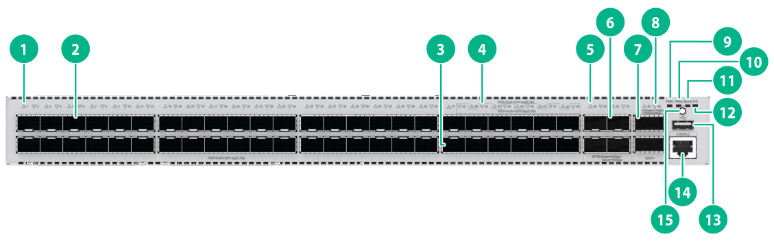
Figure2-1 Front panel

|
(1) PSFP port LED |
(2) PSFP port |
|
(3) PSFP+ port |
(4) PSFP+ port LED |
|
(5) SFP28 port LED |
(6) SFP28 port |
|
(7) QSFP+ port |
(8) QSFP+ port LED |
|
(9) Removable power supply 1 status LED (PWR1) |
(10) Removable power supply 2 status LED (PWR2) |
|
(11) Mode LED (MODE) |
(12) System status LED (SYS) |
|
(13) USB port |
(14) Console port (CONSOLE) |
|
(15) Mode button |
|
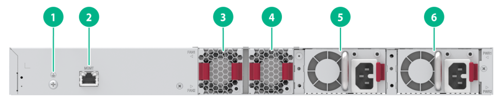
|
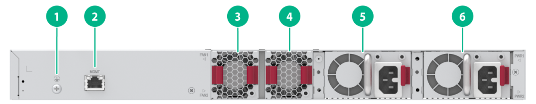
(1) Grounding screw |
(2) Management Ethernet port |
|
(3) Removable fan tray 1 |
(4) Removable fan tray 2 |
|
(5) Removable power supply 1 |
(6) Removable power supply 2 |
The FS5500-30UXS4Y2Q-EI switch came with power supply slot PWR1 empty and power supply slot PWR2 installed with a filler panel. You can install one or two power supplies for the switch as needed. In Figure2-2, two PSR600-54A-B power supplies are installed in the power supply slots.
The FS5500-30UXS4Y2Q-EI switch came with the two fan tray slots empty. You must install two fan trays of the same model for the switch. In Figure2-2, two LSPM1FANSB-SN fan trays are installed in the fan tray slots.
FS5500-48UXS4Y2Q-EI
Figure2-3 Front panel
|
(1) PSFP port LED |
(2) PSFP port |
|
(3) PSFP+ port |
(4) PSFP+ port LED |
|
(5) SFP28 port LED |
(6) SFP28 port |
|
(7) QSFP+ port |
(8) QSFP+ port LED |
|
(9) Removable power supply 1 status LED (PWR1) |
(10) Removable power supply 2 status LED (PWR2) |
|
(11) Mode LED (MODE) |
(12) System status LED (SYS) |
|
(13) USB port |
(14) Console port (CONSOLE) |
|
(15) Mode button |
|

|
(1) Grounding screw |
(2) Management Ethernet port |
|
(3) Removable fan tray 1 |
(4) Removable fan tray 2 |
|
(5) Removable power supply 1 |
(6) Removable power supply 2 |
The FS5500-48UXS4Y2Q-EI switch came with power supply slot PWR1 empty and power supply slot PWR2 installed with a filler panel. You can install one or two power supplies for the switch as needed. In Figure2-4, two PSR600-54A-B power supplies are installed in the power supply slots.
The FS5500-48UXS4Y2Q-EI switch came with the two fan tray slots empty. You must install two fan trays of the same model for the switch. In Figure2-4, two LSPM1FANSB-SN fan trays are installed in the fan tray slots.
FS5500-24UX2C-EI
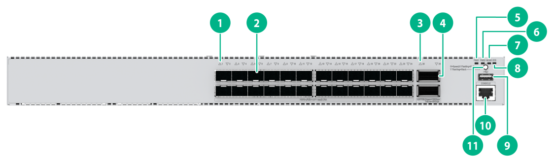
Figure2-5 Front panel
|
(1) PSFP+ port LED |
(2) PSFP+ port |
|
(3) QSFP28 port LED |
(4) QSFP28 port |
|
(5) Removable power supply 1 status LED (PWR1) |
(6) Removable power supply 2 status LED (PWR2) |
|
(7) Mode LED (MODE) |
(8) System status LED (SYS) |
|
(9) USB port |
(10) Console port (CONSOLE)) |
|
(11) Mode button |
|
|
|
NOTE: By default, the QSFP28 ports on the FS5500-24UX2C-EI switch operate at 40 Gbps. To configure the ports to operate at 100 Gbps, install a license and then execute the active port basic-license command to active the license. For more information about the command, see Interface Command Reference in the command references that come with the switch. |
|
(1) Grounding screw |
(2) Management Ethernet port |
|
(3) Removable fan tray 1 |
(4) Removable fan tray 2 |
|
(5) Removable power supply 1 |
(6) Removable power supply 2 |
The FS5500-24UX2C-EI switch came with power supply slot PWR1 empty and power supply slot PWR2 installed with a filler panel. You can install one or two power supplies for the switch as needed. In Figure2-6, two PSR600-54A-B power supplies are installed in the power supply slots.
The FS5500-24UX2C-EI switch came with the two fan tray slots empty. You must install two fan trays of the same model for the switch. In Figure2-6, two LSPM1FANSB-SN fan trays are installed in the fan tray slots.
3 Removable components
The switch supports removable components. Table3-1 describes the removable components available for the switch.
Table3-1 Compatibility matrix between the switch and removable components
|
Removable component model |
FS5500-30UXS4Y2Q-EI FS5500-48UXS4Y2Q-EI FS5500-24UX2C-EI |
|
Removable power supplies |
|
|
PSR600-54A-B |
Yes |
|
PSR920-54A-B |
Yes |
|
PSR1600-54A-B |
Yes |
|
Removable fan trays |
|
|
LSPM1FANSB-SN |
Yes |
|
|
CAUTION: You can power on the switch only when the switch has two fan trays of the same model installed. |
|
|
IMPORTANT: Do not install a PSR600-54A-B and a PSR1600-54A-B on the same switch. |
|
|
NOTE: · The power supplies support asset management. You can use the display device manuinfo command to view the name, sequence number, and vendor of the power supplies you have installed on the device. · You can install one power supply, or two power supplies for 1+1 redundancy on the switch. PoE capabilities vary by power supply configuration. When a power supply fails, PoE capabilities of the switch might degrade. For more information about PoE power capacity, see Table1-4. |
Removable power supplies
The switch uses removable power supplies and supports the PSR600-54A-B, PSR920-54A-B, and PSR1600-54A-B power supplies.
Table3-2 Removable power supplies available for the switch
|
Power supply model |
Item |
Specifications |
Reference |
|
PSR600-54A-B |
Rated input voltage range |
100 VAC to 240 VAC @ 50 Hz or 60 Hz |
H3C PSR600-54A-B Power Module User Manual |
|
Max input voltage range |
90 VAC to 290 VAC @ 47 Hz to 63 Hz |
||
|
Max output power |
600 W |
||
|
PSR920-54A-B |
Rated input voltage range |
100 VAC to 240 VAC @ 50 Hz or 60 Hz |
H3C PSR920-54A-B Power Module User Manual |
|
Max input voltage range |
90 VAC to 290 VAC @ 47 Hz to 63 Hz |
||
|
Max output power |
920 W |
||
|
PSR1600-54A-B |
Rated input voltage range |
100 VAC to 240 VAC @ 50 Hz or 60 Hz |
H3C PSR1600-54A-B Power Module User Manual |
|
Max input voltage range |
90 VAC to 290 VAC @ 47 Hz to 63 Hz |
||
|
Max output power |
1600 W |
Removable fan trays
|
|
CAUTION: You can power on the switch only when the switch has two fan trays of the same model installed. |
The switch uses removable fan trays and supports the LSPM1FANSB-SN fan tray.
Table3-3 Removable fan trays
|
Item |
Specifications |
|
LSPM1FANSB-SN fan tray |
|
|
Dimensions |
40 × 40.6 × 105 mm (1.57 × 1.60 × 4.13 in) |
|
Fan speed |
20000 R.P.M |
|
Max airflow |
20 CFM (0.57 m3/min) |
|
Airflow direction |
Draws air from the port side to the power supply side |
|
Input voltage |
12 V |
|
Power consumption |
9.8 W |
|
Reference |
H3C LSPM1FANSA-SN & LSPM1FANSB-SN Fan Trays User Guide |
4 Ports and LEDs
Ports
Console port
Table4-1 Console port specifications
|
Item |
Specification |
|
Connector type |
RJ-45 |
|
Compliant standard |
EIA/TIA-232 |
|
Transmission baud rate |
9600 bps (default) to 115200 bps |
|
Services |
· Provides connection to an ASCII terminal. · Provides connection to the serial port of a local PC running terminal emulation program. |
|
Available switch models |
All switch models |
Management Ethernet port
Table4-2 Management Ethernet port specifications
|
Item |
Specification |
|
Connector type |
RJ-45 |
|
Transmission rate, duplex mode, and auto MDI/MDI-X |
· 10 Mbit/s, half/full-duplex · 100 Mbit/s, half/full-duplex · 1000 Mbit/s, full-duplex · MDI/MDI-X, autosensing |
|
Transmission medium |
Category-5 (or above) twisted pair cable |
|
Max transmission distance |
100 m (328.08 ft) |
|
Compatible standards |
· IEEE 802.3i · IEEE 802.3u · IEEE 802.3ab |
|
Functions and services |
Connects to a computer or remote network management work station for upgrading and managing applications and Boot ROM |
|
Available switch models |
All switch models |
USB port
Table4-3 USB port specifications
|
Item |
Specifications |
|
Interface type |
USB 2.0 |
|
Compliant standard |
OHC |
|
Port transmission rate |
Uploads and downloads data at a rate up to 480 Mbps |
|
Functions and services |
Accesses the file system on the flash of the switch, for example, to upload or download application and configuration files |
|
Available switch models |
All switch models |
|
|
NOTE: USB devices from different vendors vary in compatibilities and drivers. H3C does not guarantee correct operation of USB devices from other vendors on the switch. If a USB device fails to operate on the switch, replace it with one from another vendor. |
PSFP port
PSFP ports can provide 1 Gbps data links and supply power for wireless APs or powered switches through hybrid copper-fiber cables.
Table4-4 PSFP port specifications
|
Item |
Specifications |
|
Available transceiver modules and cables |
· FE SFP transceiver modules in Table4-5 · GE SFP transceiver modules and cables in Table4-7 |
|
Available switch models |
FS5500-30UXS4Y2Q-EI, FS5500-48UXS4Y2Q-EI |
|
Restrictions and guidelines |
· A PSFP port can provide 1 Gbps data links and supply PoE power at the same time only when it is installed with an SFP-GE-POE transceiver module · You can install a maximum of 20 SFP-GE-T transceiver modules on an FS5500-48UXS4Y2Q-EI switch |
Table4-5 FE SFP transceiver modules available for the PSFP ports
|
FE SFP transceiver module |
Central wavelength (nm) |
Connector |
Fiber type and diameter (µm) |
Max transmission distance |
|
SFP-FE-SX-MM1310-A |
1310 |
LC |
Multi-mode, 50/125 |
2 km (1.24 miles) |
|
Multi-mode, 62.5/125 |
||||
|
SFP-FE-LX-SM1310-A |
1310 |
LC |
Single-mode, 9/125 |
15 km (9.32 miles) |
|
SFP-FE-LH40-SM1310 |
1310 |
LC |
Single-mode, 9/125 |
40 km (24.86 miles) |
|
SFP-FE-LH80-SM1550 |
1550 |
LC |
Single-mode, 9/125 |
80 km (49.71 miles) |
|
SFP-FE-LX-SM1310-BIDI |
TX: 1310 RX: 1550 |
LC |
Single-mode, 9/125 |
15 km (9.32 miles) |
|
SFP-FE-LX-SM1550-BIDI |
TX: 1550 RX: 1310 |
LC |
Single-mode, 9/125 |
15 km (9.32 miles) |
|
SFP-FE-BX15-U-SM1310 |
1310 |
LC |
Single-mode, 9/125 |
15 km (9.32 miles) |
|
|
IMPORTANT: The SFP-FE-LX-SM1310-BIDI and SFP-FE-LX-SM1550-BIDI transceiver modules must be used in pairs. For example, if one end uses the SFP-FE-LX-SM1310-BIDI transceiver module, the other end must use the SFP-FE-LX-SM1550-BIDI transceiver module. |
|
|
NOTE: · As a best practice, use H3C transceiver modules and cables for the switch. · The H3C transceiver modules and cables are subject to change over time. For the most recent list of H3C transceiver modules and cables, contact your H3C Support or marketing staff. · For more information about H3C transceiver modules and cables, see H3C Transceiver Modules User Guide. |
PSFP+ port
PSFP+ ports can provide 1 Gbps or 10 Gbps data links and supply power for wireless APs or powered switches through hybrid copper-fiber cables.
Table4-6 PSPF+ port specifications
|
Item |
Specifications |
|
Available transceiver modules and cables |
· GE SFP transceiver modules and cables in Table4-7 · 10-GE SFP+ transceiver modules and cables in Table4-8 and Table4-9 |
|
Available switch models |
All switch models |
|
Restrictions and guidelines |
· A PSFP+ port can provide 10 Gbps data links and receive or supply PoE power at the same time only when it is installed with an SFP-XG-POE-MR transceiver module · A PSFP+ port can provide 1 Gbps data links and receive or supply PoE power at the same time only when it is installed with an SFP-GE-POE transceiver module |
Table4-7 GE SFP transceiver modules and cables
|
GE SFP transceiver module/cable |
Central wavelength (nm) |
Connector |
Cable/Fiber type and diameter (µm) |
Modal bandwidth (MHz*km) |
Max. transmission distance |
|
SFP transceiver module |
|||||
|
SFP-GE-T |
N/A |
RJ-45 |
Twisted pair cable |
N/A |
100 m (328.08 ft) |
|
SFP-GE-POE |
1310 |
LC |
SMF |
N/A |
10 km (6.21 miles) |
|
SFP-GE-SX-MM850-A |
850 |
LC |
Multi-mode, 50/125 |
500 |
550 m (1804.46 ft) |
|
400 |
500 m (1640.42 ft) |
||||
|
Multi-mode, 62.5/125 |
200 |
275 m (902.23 ft) |
|||
|
160 |
200 m (656.17 ft) |
||||
|
SFP-GE-LX-SM1310-A |
1310 |
LC |
Single-mode, 9/125 |
N/A |
10 km (6.21 miles) |
|
Multi-mode, 50/125 |
500/400 |
550 m (1804.46 ft) |
|||
|
Multi-mode, 62.5/125 |
500 |
550 m (1804.46 ft) |
|||
|
SFP-GE-LH40-SM1310 |
1310 |
LC |
Single-mode, 9/125 |
N/A |
40 km (24.86 miles) |
|
SFP-GE-LH40-SM1550 |
1550 |
LC |
Single-mode, 9/125 |
N/A |
40 km (24.86 miles) |
|
SFP-GE-LH80-SM1550 |
1550 |
LC |
Single-mode, 9/125 |
N/A |
80 km (49.71 miles) |
|
SFP-GE-LH100-SM1550 |
1550 |
LC |
Single-mode, 9/125 |
N/A |
100 km (62.14 miles) |
|
SFP-GE-LX-SM1310-BIDI |
TX: 1310 RX: 1490 |
LC |
Single-mode, 9/125 |
N/A |
10 km (6.21 miles) |
|
SFP-GE-LX-SM1490-BIDI |
TX: 1490 RX: 1310 |
||||
|
SFP-GE-LH40-SM1310-BIDI |
TX: 1310 RX: 1550 |
LC |
Single-mode, 9/125 |
N/A |
40 km (24.86 miles) |
|
SFP-GE-LH40-SM1550-BIDI |
TX: 1550 RX: 1310 |
||||
|
SFP-GE-LH70-SM1490-BIDI |
TX: 1490 RX: 1550 |
LC |
Single-mode, 9/125 |
N/A |
70 km (43.50 miles) |
|
SFP-GE-LH70-SM1550-BIDI |
TX: 1550 RX: 1490 |
||||
|
SFP cable |
|||||
|
SFP-STACK-Kit |
N/A |
N/A |
SFP cable |
N/A |
1.5 m (4.92 ft) |
|
|
IMPORTANT: The SFP-GE-LX-SM1310-BIDI and SFP-GE-LX-SM1490-BIDI transceiver modules, the SFP-GE-LH40-SM1310-BIDI and SFP-GE-LH40-SM1550-BIDI transceiver modules, and the SFP-GE-LH70-SM1490-BIDI and SFP-GE-LH70-SM1550-BIDI transceiver modules must be used in pairs. For example, if one end uses an SFP-GE-LX-SM1310-BIDI transceiver module, the other end must use an SFP-GE-LX-SM1490-BIDI transceiver module. |
Table4-8 10-GE SFP+ transceiver modules
|
10-GE SFP+ transceiver module |
Central wavelength (nm) |
Connector |
Fiber type and diameter (µm) |
Modal bandwidth (MHz*km) |
Max. transmission distance |
|
SFP-XG-SX-MM850-D |
850 |
LC |
Multi-mode, 50/125 |
2000 |
300 m (984.25 ft) |
|
500 |
82 m (269.03 ft) |
||||
|
400 |
66 m (216.54 ft) |
||||
|
Multi-mode, 62.5/125 |
200 |
33 m (108.27 ft) |
|||
|
160 |
26 m (85.30 ft) |
||||
|
SFP-XG-LX-SM1310-D |
1310 |
LC |
Single-mode, 9/125 |
N/A |
10 km (6.21 miles) |
|
SFP-XG-POE-MR |
1310 |
LC |
SMF |
N/A |
1.4 km (0.87 miles) |
|
SFP-XG-LH40-SM1550 |
1550 |
LC |
Single-mode, 9/125 |
N/A |
40 km (24.86 miles) |
|
SFP-XG-LH80-SM1550 |
1550 |
LC |
Single-mode, 9/125 |
N/A |
80 km (49.71 miles) |
|
SFP-XG-LX-SM1270-BIDI |
TX: 1270 RX: 1330 |
LC |
Single-mode, 9/125 |
N/A |
10 km (6.21 miles) |
|
SFP-XG-LX-SM1330-BIDI |
TX: 1330 RX: 1270 |
||||
|
SFP-XG-LH40-SM1270-BIDI |
TX: 1270 RX: 1330 |
LC |
Single-mode, 9/125 |
N/A |
40 km (24.86 miles) |
|
SFP-XG-LH40-SM1330-BIDI |
TX: 1330 RX: 1270 |
Single-mode, 9/125 |
N/A |
40 km (24.86 miles) |
|
|
SFP-XG-LH80-SM1490-BIDI |
TX: 1490 RX: 1550 |
LC |
Single-mode, 9/125 |
N/A |
80 km (49.71 miles) |
|
SFP-XG-LH80-SM1550-BIDI |
TX: 1550 RX: 1490 |
Single-mode, 9/125 |
N/A |
80 km (49.71 miles) |
|
|
IMPORTANT: The SFP-XG-LX-SM1270-BIDI and SFP-XG-LX-SM1330-BIDI transceiver modules, the SFP-XG-LH40-SM1270-BIDI and SFP-XG-LH40-SM1330-BIDI transceiver modules, and SFP-XG-LH80-SM1490-BIDI and SFP-XG-LH80-SM1550-BIDI transceiver modules must be used in pairs. For example, if one end uses an SFP-XG-LX-SM1270-BIDI transceiver module, the other end must use an SFP-XG-LX-SM1330-BIDI transceiver module. |
Table4-9 SFP+ copper and fiber cables available for the PSFP+ ports
|
Item |
Cable length |
|
SFP+ copper cable |
|
|
LSWM1STK |
0.65 m (2.13 ft) |
|
LSWM2STK |
1.2 m (3.94 ft) |
|
LSWM3STK |
3 m (9.84 ft) |
|
LSTM1STK |
5 m (16.40 ft) |
|
SFP+ fiber cable |
|
|
SFP-XG-D-AOC-7M |
7 m (22.97 ft) |
|
SFP-XG-D-AOC-10M |
10 m (32.81 ft) |
|
SFP-XG-D-AOC-20M |
20 m (65.62 ft) |
|
|
NOTE: · As a best practice, use H3C transceiver modules and cables for the switch. · The H3C transceiver modules and cables are subject to change over time. For the most recent list of H3C transceiver modules and cables, contact your H3C Support or marketing staff. · For more information about H3C transceiver modules and cables, see H3C Transceiver Modules User Guide. |
Figure4-1 SFP+ cable
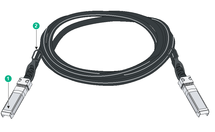
|
(1) Connector |
(2) Pull latch |
SFP28 port
Table4-10 SFP28 port specifications
|
Item |
Specifications |
|
Compatible transceiver modules and cables |
· 10-GE SFP+ transceiver modules and cables in Table4-8 and Table4-9 · 25-GE SFP28 transceiver modules and cables in Table4-11 and Table4-12 |
|
Compatible devices |
FS5500-30UXS4Y2Q-EI, FS5500-48UXS4Y2Q-EI |
Table4-11 25-GE SFP28 transceiver modules available for the SFP28 ports
|
25-GE SFP28 transceiver module |
Central wavelength (nm) |
Connector |
Fiber type and diameter (µm) |
Modal bandwidth (MHz*km) |
Maximum transmission distance |
|
SFP-25G-SR-MM850 |
850 |
LC |
Multi-mode, 50/125 |
2000 |
70 m (229.66 ft) |
|
4700 |
100 m (328.08 ft) |
||||
|
SFP-25G-LR-SM1310 |
1310 |
LC |
Single-mode, 9/125 |
N/A |
10 km (6.21 miles) |
Table4-12 25G SFP28 copper and fiber cables available for the SFP28 ports
|
Item |
Cable length |
|
25G SFP28 copper cable |
|
|
SFP-25G-D-CAB-1M |
1 m (3.28 ft) |
|
SFP-25G-D-CAB-3M |
3 m (9.84 ft) |
|
SFP-25G-D-CAB-5M |
5 m (16.40 ft) |
|
25G SFP28 fiber cable |
|
|
SFP-25G-D-AOC-3M |
3 m (9.84 ft) |
|
SFP-25G-D-AOC-5M |
5 m (16.40 ft) |
|
SFP-25G-D-AOC-7M |
7 m (22.97 ft) |
|
SFP-25G-D-AOC-10M |
10 m (32.81 ft) |
|
SFP-25G-D-AOC-20M |
20 m (65.62 ft) |
|
|
NOTE: · As a best practice, use H3C transceiver modules and cables for the switch. · The H3C transceiver modules and cables are subject to change over time. For the most recent list of H3C transceiver modules and cables, contact your H3C Support or marketing staff. · For more information about H3C transceiver modules and cables, see H3C Transceiver Modules User Guide. |
Figure4-2 SFP28 cable
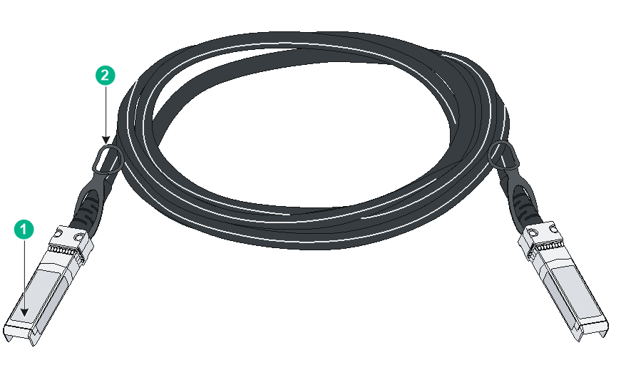
|
(1) Connector |
(2) Pull latch |
QSFP+ port
Table4-13 QSFP+ port specifications
|
Item |
Specifications |
|
Available transceiver modules and cables |
QSFP+ transceiver modules and cables in Table4-14 and Table4-15 |
|
Available switch models |
FS5500-30UXS4Y2Q-EI, FS5500-48UXS4Y2Q-EI |
Table4-14 QSFP+ transceiver modules available for the QSFP+ ports
|
QSFP+ transceiver module |
Central wavelength (nm) |
Connector |
Fiber type and diameter (µm) |
Modal bandwidth (MHz × km) |
Max transmission distance |
|
QSFP-40G-SR4-MM850 |
850 |
MPO |
Multi-mode, 50/125 |
2000 |
100 m (328.08 ft) |
|
4700 |
150 m (492.13 ft) |
||||
|
QSFP-40G-CSR4-MM850 |
850 |
MPO |
Multi-mode, 50/125 |
2000 |
300 m (984.25 ft) |
|
4700 |
400 m (1312.34 ft) |
||||
|
QSFP-40G-LR4-WDM1300 |
Four lanes: · 1271 · 1291 · 1311 · 1331 |
LC |
Single-mode, 9/125 |
N/A |
10 km (6.21 miles) |
|
QSFP-40G-LR4L-WDM1300 |
Four lanes: · 1271 · 1291 · 1311 · 1331 |
LC |
Single-mode, 50/125 |
N/A |
2 km (1.24 miles) |
|
QSFP-40G-BIDI-SR-MM850 |
850 |
LC |
Multi-mode, 50/125 |
2000 |
100 m (328.08 ft) |
|
4700 |
150 m (492.13 ft) |
||||
|
QSFP-40G-BIDI-WDM850 |
Four lanes: · 850 · 880 · 910 · 940 |
LC |
Multi-mode, 50/125 |
2000 |
240 m (787.40 ft) |
|
4700 |
350 m (1148.29 ft) |
||||
|
QSFP-40G-ER4-WDM1300 |
Four lanes: · 1271 · 1291 · 1311 · 1331 |
LC |
Single-mode, 50/125 |
N/A |
40 km (24.86 miles) |
Table4-15 40G QSFP+ copper and fiber cables available for the QSFP+ ports
|
Item |
Cable length |
|
QSFP+ copper cable |
|
|
LSWM1QSTK0 |
1 m (3.28 ft) |
|
LSWM1QSTK1 |
3 m (9.84 ft) |
|
LSWM1QSTK2 |
5 m (16.40 ft) |
|
QSFP+ fiber cable |
|
|
QSFP-40G-D-AOC-3M |
3 m (9.84 ft) |
|
QSFP-40G-D-AOC-7M |
7 m (22.97 ft) |
|
QSFP-40G-D-AOC-10M |
10 m (32.81 ft) |
|
QSFP-40G-D-AOC-20M |
20 m (65.62 ft) |
|
|
NOTE: · As a best practice, use H3C transceiver modules and cables for the switch. · The H3C transceiver modules and cables are subject to change over time. For the most recent list of H3C transceiver modules and cables, contact your H3C Support or marketing staff. · For more information about H3C transceiver modules and cables, see H3C Transceiver Modules User Guide. |
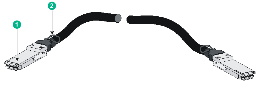
|
(1) Connector |
(2) Pull latch |
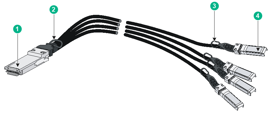
Figure4-4 40G QSFP+ to 4x10G SFP+ cable
|
(1) QSFP+ connector |
(2) QSFP+ side pull latch |
|
(3) SFP+ side pull latch |
(4) SFP+ connector |
QSFP28 port
Table4-16 QSFP28 port specifications
|
Item |
Specifications |
|
Available transceiver modules and cables |
· QSFP+ transceiver modules and cables in Table4-14 and Table4-15 · QSFP28 transceiver modules and cables in Table4-17 and Table4-18 |
|
Available switch models |
FS5500-24UX2C-EI |
Table4-17 QSFP28 transceiver modules available for the QSFP28 ports
|
QSFP28 transceiver module |
Central wavelength (nm) |
Connector |
Fiber type and diameter (µm) |
Modal bandwidth (MHz × km) |
Max transmission distance |
|
QSFP-100G-SR4-MM850 |
850 |
MPO |
Multi-mode, 50/125 |
2000 |
70 m (229.66 ft) |
|
4700 |
100 m (328.08 ft) |
||||
|
QSFP-100G-LR4-WDM1300 |
Four lanes: · 1295.56 · 1300.05 · 1304.58 · 1309.14 |
SMF |
Single-mode, 9/125 |
N/A |
10 km (6.21 miles) |
|
QSFP-100G-LR4L-WDM1300 |
Four lanes: · 1271 · 1291 · 1311 · 1331 |
LC |
Single-mode, 9/125 |
N/A |
2 km (1.24 miles) |
|
QSFP-100G-ER4L-WDM1300 |
Four lanes: · 1295.56 · 1300.05 · 1304.58 · 1309.14 |
SMF |
Single-mode, 9/125 |
N/A |
40 km (24.86 miles) |
|
QSFP-100G-BIDI-MM850 |
Two lanes: · 855 · 908 |
MMF |
Multi-mode, 50/125 |
2000 |
70 m (229.66 ft) |
|
4700 |
100 m (328.08 ft) |
Table4-18 100G QSFP28 fiber and copper cables available for the QSFP28 ports
|
Item |
Cable length |
|
QSFP28 fiber cable |
|
|
QSFP-100G-D-AOC-7M |
7 m (22.97 ft) |
|
QSFP-100G-D-AOC-10M |
10 m (32.81 ft) |
|
QSFP-100G-D-AOC-20M |
20 m (65.62 ft) |
|
QSFP28 copper cable |
|
|
QSFP-100G-D-CAB-1M |
1 m (3.28 ft) |
|
QSFP-100G-D-CAB-3M |
3 m (9.84 ft) |
|
QSFP-100G-D-CAB-5M |
5 m (16.40 ft) |
LEDs
System status LED
The system status LED shows the operating status of the switch.
Table4-19 System status LED description
|
LED mark |
Status |
Description |
|
SYS |
Steady green |
The switch has started correctly. |
|
Flashing green (1 Hz) |
The switch is performing power-on self test (POST). |
|
|
Steady red |
The switch has failed POST or is faulty. |
|
|
Off |
The switch is powered off. |
Power supply status LED
The switch provides PWR1 and PWR2 LEDs on the front panel to indicate the operating status of the power supplies.
Table4-20 Power supply status LED description
|
LED mark |
Status |
Description |
|
PWR1/PWR2 |
Steady green |
A power supply is installed in the power supply slot, and the power supply is outputting power correctly. |
|
Steady yellow |
A power supply is installed in the power supply slot, but the power supply is faulty or no power is being supplied to the power supply. |
|
|
Off |
No power supply is installed in the power supply slot. |
Mode LED (MODE)
The mode LED works in conjunction with the port LEDs to indicate the operating state of the ports and the switch.
The mode LED indicates the type of information that the port LEDs are showing.
You can use the mode button to change the indication of the mode LED. After you press the mode button for the mode LED to steady yellow, flashing green, or flashing yellow, the mode LED keeps that state for only 45 seconds and then turns steady green automatically.
Table4-21 Description for the mode LED
|
LED mark |
Status |
Description |
|
Mode LED (MODE) |
Steady green |
The port LEDs are showing link state of the ports. |
|
Flashing green |
The port LEDs are showing the PoE status of the ports. |
|
|
Flashing yellow |
The port LEDs work in conjunction to indicate the IRF member ID of the switch. For example, if the LED for port 4 is steady green, the IRF member ID of the switch is 4. |
PSFP port LED
Table4-22 PSFP port LED description
|
Status |
Description |
|
|
Mode LED |
PSFP port LED |
|
|
Steady green (rate mode) |
Steady green |
A link is present on the port and the port is operating at 1000 Mbps. |
|
Flashing green |
The port is sending or receiving data at 1000 Mbps. |
|
|
Steady yellow |
A link is present on the port and the port is operating at 100 Mbps. |
|
|
Flashing yellow |
The port is sending or receiving data at 100 Mbps. |
|
|
Off |
No link is present on the port. |
|
|
Flashing green (PoE mode) |
Steady green |
PoE power supply is normal. |
|
Flashing green |
· The maximum PoE power provided by the port fails to meet the power requirement of the PD. · The remaining power of the switch fails to meet the power supply requirement of the port. |
|
|
Steady yellow |
The port has failed to supply power. |
|
|
Off |
The port is not supplying power through PoE. |
|
|
Flashing yellow (IRF mode) |
Steady green |
The PSFP port LEDs on the switch work in conjunction to indicate the IRF member ID of the switch. For example, if the LED for port 4 is steady green and the other port LEDs are off, the IRF member ID of the switch is 4. |
PSFP+ port LED
Table4-23 PSFP+ port LED description
|
Status |
Description |
|
|
Mode LED |
PSFP+ port LED |
|
|
Steady green (rate mode) |
Steady green |
A link is present on the port and the port is operating at 10 Gbps. |
|
Flashing green |
The port is sending or receiving data at 10 Gbps. |
|
|
Steady yellow |
A link is present on the port and the port is operating at 1 Gbps. |
|
|
Flashing yellow |
The port is sending or receiving data at 1 Gbps. |
|
|
Off |
No link is present on the port. |
|
|
Flashing green (PoE mode) |
Steady green |
PoE power supply is normal. |
|
Flashing green |
· The maximum PoE power provided by the port fails to meet the power requirement of the PD. · The remaining power of the switch fails to meet the power supply requirement of the port. |
|
|
Steady yellow |
The port has failed to supply power. |
|
|
Off |
The port is not supplying power through PoE. |
|
|
Flashing yellow (IRF mode) |
Off |
The mode LED is operating in IRF mode. |
SFP28 port LED
Table4-24 SFP28 port LED description
|
SFP28 port LED status |
Description |
|
Steady green |
A link is present on the port and the port is operating at 25 Gbps. |
|
Flashing green |
The port is sending or receiving data at 25 Gbps. |
|
Steady yellow |
A link is present on the port and the port is operating at 10 Gbps. |
|
Flashing yellow (3 Hz) |
The port is sending or receiving data at 10 Gbps. |
|
Off |
No transceiver module is installed in the port or no link is present on the port. |
QSFP+ port LED
Table4-25 QSFP+ port LED description
|
QSFP+ port LED status |
Description |
|
Steady green |
A link is present on the port and the port is operating at 40 Gbps. |
|
Flashing green |
The port is sending or receiving data at 40 Gbps. |
|
Off |
· No transceiver module is installed in the port or no link is present on the port. · The mode LED is operating in IRF mode. |
QSFP28 port LED
Table4-26 QSFP28 port LED description
|
QSFP28 port LED status |
Description |
|
Steady green |
A link is present on the port and the port is operating at 100 Gbps. |
|
Flashing green |
The port is sending or receiving data at 100 Gbps. |
|
Steady yellow |
A link is present on the port and the port is operating at 40 Gbps. |
|
Flashing yellow |
The port is sending or receiving data at 40 Gbps. |
|
Off |
· No transceiver module is installed in the port or no link is present on the port. · The mode LED is operating in IRF mode. |
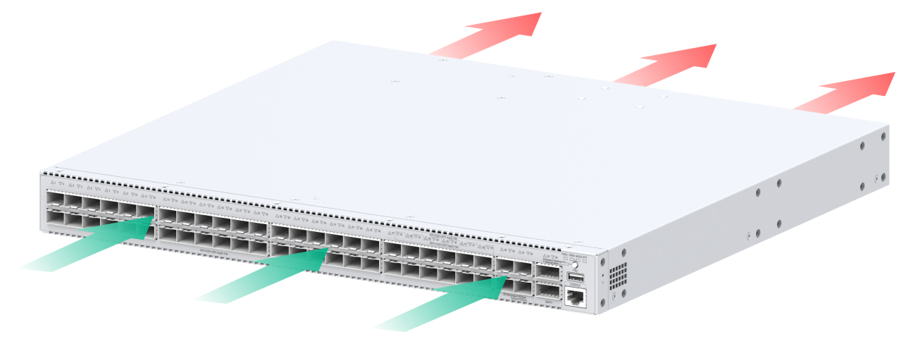
5 Cooling system
To dissipate heat timely and enhance system stability, the switch uses a high-performance cooling system. Consider the site ventilation design when you plan the installation site for the switch.
The switch uses removable fan trays. For adequate heat dissipation, you must install two fan trays of the same model for the switch.
Table5-1 Fan trays available for the switch
|
Device model |
Fan tray type |
Airflow direction |
|
FS5500-30UXS4Y2Q-EI FS5500-48UXS4Y2Q-EI FS5500-24UX2C-EI |
LSPM1FANSB-SN |
From the side panels and port side to the power supply side |
Figure5-1 Airflow direction (FS5500-48UXS4Y2Q-EI)