- Table of Contents
- Related Documents
-
| Title | Size | Download |
|---|---|---|
| 04-H3C vBRAS CUPS BRAS Services Deployment Guide | 5.24 MB |
Contents
vBRAS-CP and vBRAS-UP functionalities
Configuring the CUSP controller
Configuring the listening IP address for the CUSP controller
Configuring the NETCONF client
Configuring a NETCONF connection profile
Configuring a UP management instance
Configuring the parameters for the protocol channel between the CP and UP
Binding an IP address pool to a CPDR group
Adding a UP to a UP backup group
Configuring a UP backup profile
Configuring the subnet allocation mode and prefix range allocation mode
NAS-Port-ID three-/four-dimensional interfaces
Example: Configuring CPDR and UP 1:3 warm standby mode for PPPoE
Example: Configuring CPDR and UP 1:3 warm standby mode for IPoE
Example: Configuring CPDR and UP 1:3 warm standby mode for PPPoE and CGN
Example: Configuring CPDR and UP 1:3 warm standby mode for PPPoE multicast
Example: Configuring CPDR and UP 1:3 warm standby mode for L2TP
Example: Configuring CPDR and UP 1:3 warm standby mode for IPoE+VPN
Example: Configuring CPDR and UP 1:3 warm standby mode for PPPoE+VPN
Example: Configuring CPDR and UP 1:3 warm standby mode for PPPoE CGN+VPN
Example: Configuring CPDR and UP 1:3 warm standby mode for L2TP+VPN
Example: Configuring CPDR and UP 1:3 warm standby mode for PPPoE+multicast VPN
Example: Configuring CPDR and UP 1:3 warm standby mode for static IPoE
Example: Configuring CPDR and UP 1:3 warm standby mode for static IPoE+VPN
Example: Configuring CPDR and UP 1:3 warm standby mode for IPoE+Web+CGN+VPN
Example: Configuring CPDR and UP 1:3 warm standby mode for IPoE+Web+CGN
Example: Configuring SRv6 for vBRAS-UPs
Manually scaling out the vBRAS-CP through the VNFM-vBRAS
Introduction
This document is applicable to the products and versions in Table 1.
Table 1 Applicable products and software versions
|
Hardware |
Product versions |
|
SR8800-X |
R8380P09 |
|
SR8800-X-S |
R8385P09 |
|
SR8800-F |
R8385P09 |
|
CR16000-F |
R8385P09 |
|
CR16000-M |
R8385P09 |
|
vBRAS1000-CP |
E2021P20 |
|
vBRAS1000-vUP |
E3021P20 |
Conventions
Screenshots and examples provided in this documentation are for illustration only. They might differ depending on the hardware model, software version, and configuration. Examples in this document might use devices that differ from your device in hardware model, configuration, or software version.
It is normal that the port numbers, sample output, screenshots, and other information in the examples differ from what you have on your device.
About MAN
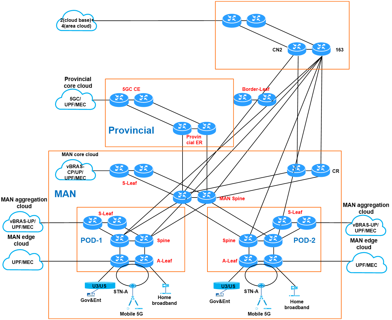
To achieve high-speed and sustainable development of telecommunications services, it is necessary to seek breakthroughs in network capacity, business models, service provisioning, and O&M. For this purpose, China Telecom has proposed a new MAN solution that focuses on fixed-mobile consolidation, business and network separation, and cloud-network collaboration.
The new MAN evolves from the existing telecommunications MAN structure by incorporating the fabric network architecture and a vBRAS CUPS system to restructure traditional MSE services. It also introduces SRv6 solutions and new hardware for end-to-end network segmentation. Based on technologies like SRv6, EVPN, and FlexE, with the vBRAS system acting as the business control point and coupled with automated service deployment by the SDN controller, this design paves the way for the China Telecom's future-oriented new MAN.
The vBRAS CUPS technology centrally pools the business control layer for reliable service access and efficient resource usage. This technology deploys the CT cloud as the brain of the new-generation MAN to enable intelligent management and scheduling.
Figure 1 Target topology for the new MAN
System description
Technical background
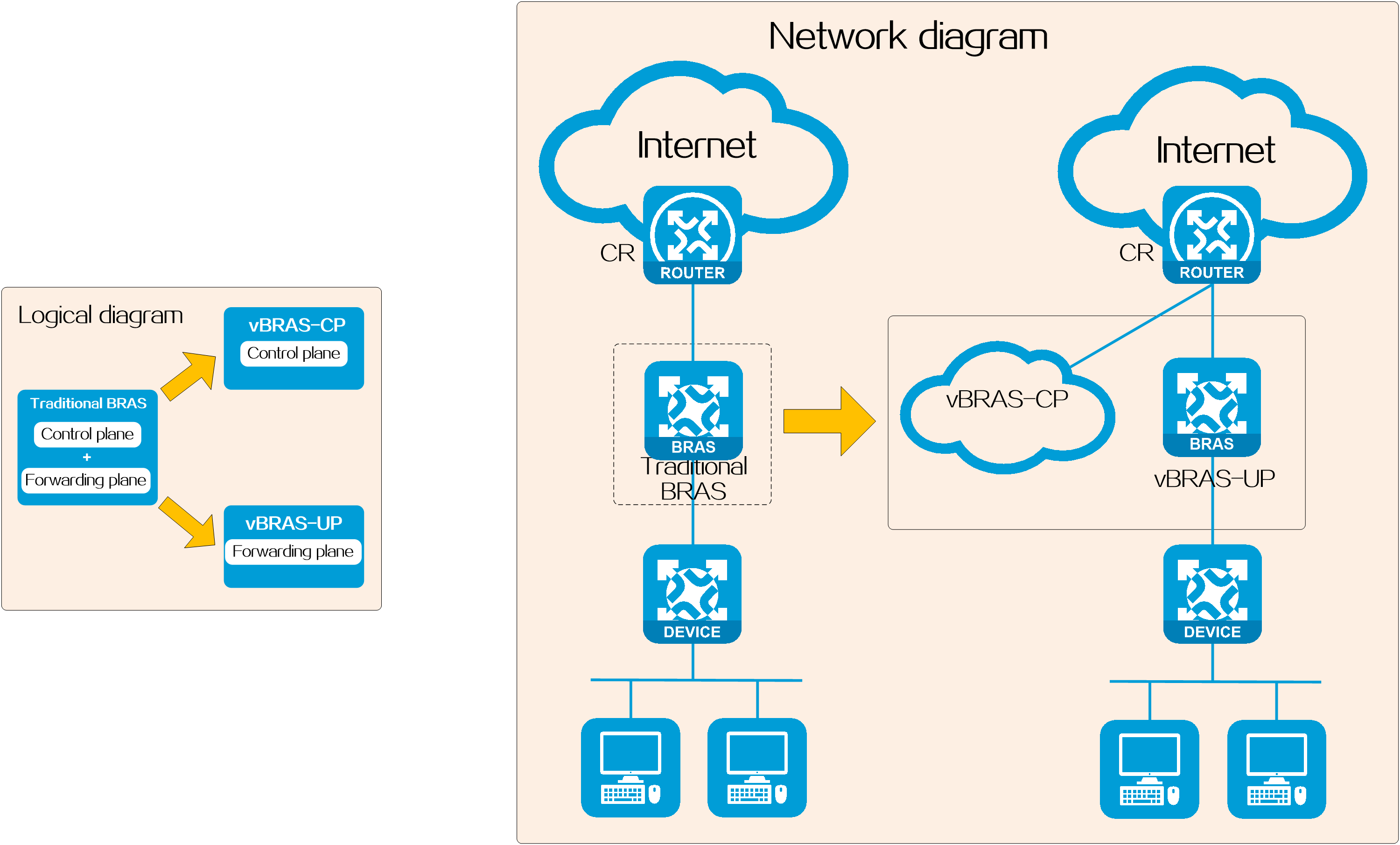
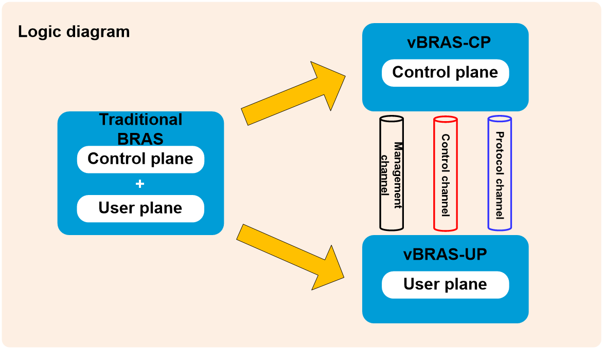
To address issues in traditional BRASs such as mismatched capabilities between the control plane and forwarding plane, lack of resource sharing, and slow new service deployment, the industry has proposed the vBRAS system architecture based on the CUPS technology.
The vBRAS system architecture based on the CUPS technology contains two roles: vBRAS-CP (CP for short) and vBRAS-UP (UP for short), which together fulfill BRAS functions.
· Control planes (CPs)—Provide control plane functions such as user authentication, and address allocation and management.
· User planes (UPs)—Provide user plane functions such as user data traffic forwarding and traffic control. A UP can be one of the following types depending on its form factor:
¡pUP—A physical device acting as a UP. You typically deploy a pUP to provide high forwarding performance, for example, for large-size flow services such as broadband access and IPTV.
¡vUP—A virtual device acting as a UP. With strong computing capability, vUPs can handle large-session, small-traffic demands such as ITMS and VoIP services.
Figure 2 Logic function schematic diagram
System architecture
The vBRAS CUPS architecture was designed in compliance with the ETSI network function virtualization (NFV) framework, as shown in Figure 3. This architecture replaces traditional expensive BRAS physical hardware with cheap commercial x86 servers. It abstracts the network functionalities of traditional BRAS servers into software entities called vBRAS servers. You can quickly add or remove vBRAS servers to accommodate new services or changes that arise as business grows. Each vBRAS server is a failure domain and is self-healing. The issues in one vBRAS server do not affect other vBRAS servers. In addition, this architecture also supports automated deployment.
Figure 3 vBRAS CUPS system architecture
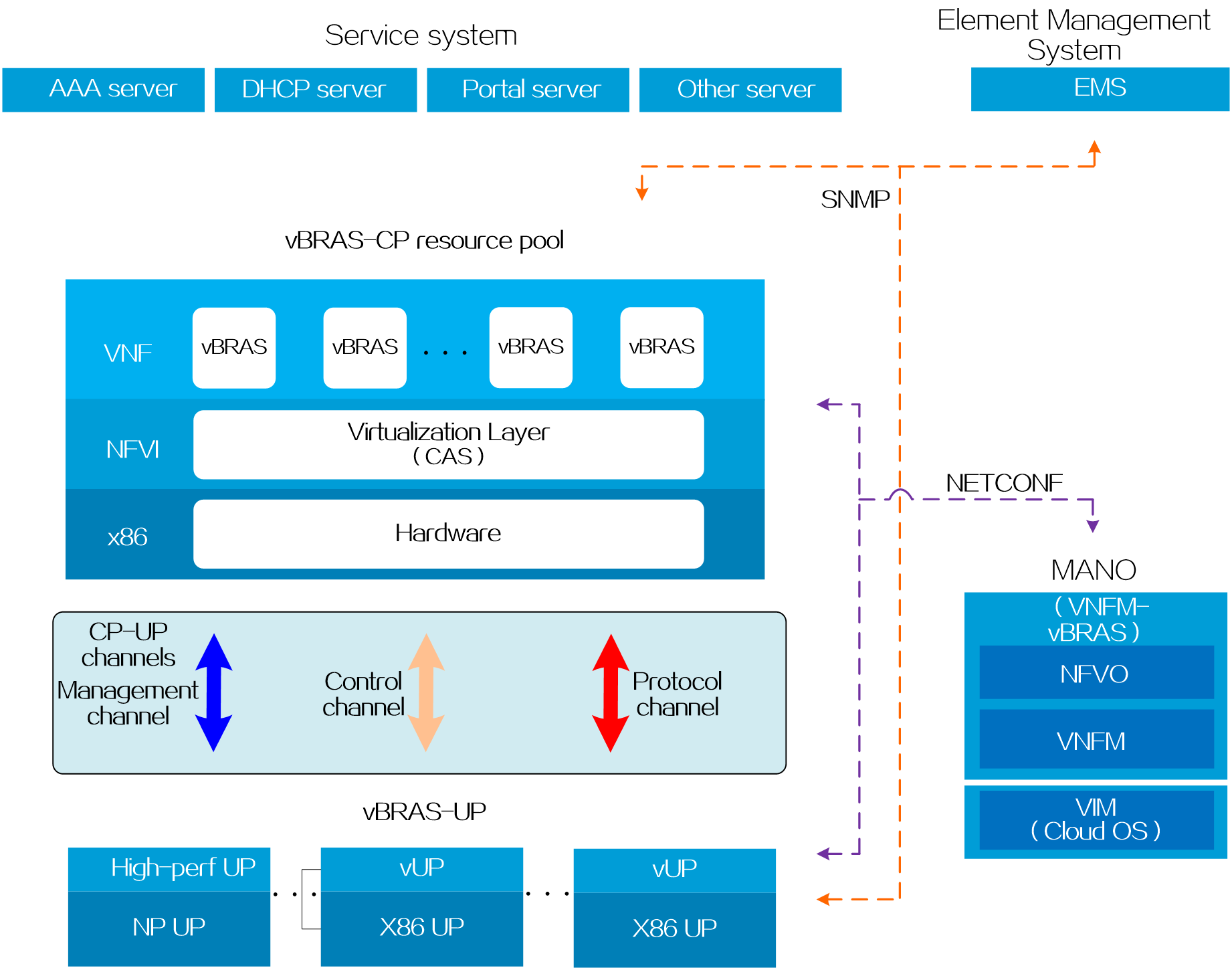
The vBRAS CUPS architecture contains the following components:
· vBRAS-CP—Provides control plane services such as user identification and address allocation and management. A vBRAS-CP is deployed as an expandable pool of resources to provide strong compute performance. A vBRAS-CP is also called a CP for simplicity. The vBRAS-CP architecture contains the following layers:
¡Virtualized network function (VNF) layer—Contains virtualized network functions built on top of network function virtualization infrastructure (NFVI) to provide the same network services as physical network devices. This layer deploys VNFs in the VM form factor and it contains CTRL-VMs, BRAS-VMs, FWD-VMs, and DB-VMs to fulfill vBRAS-CP functionalities.
¡NFVI layer—Virtualizes compute, storage, and network hardware resources into virtualized resources for deployment of VNFs. The vBRAS CUPS architecture uses the H3C CAS cloud platform as the NFVI.
¡x86 server layer—Provides underlying physical hardware resources.
· vBRAS-UP—Provides forwarding plane services to forward data packets and control traffic. A vBRAS-UP is also called a UP for simplicity. A UP can be one of the following types depending on its form factor:
¡vBRAS-pUP—The UP is a physical device. A vBRAS-pUP is also called a pUP for simplicity. You typically deploy a pUP to provide high forwarding performance, for example, for large-size flow services such as broadband access and IPTV.
¡vBRAS-vUP—The UP is a virtual device. A vBRAS-vUP is also called a vUP for simplicity. With strong computing capability, vUPs can handle large-session, small-traffic demands such as ITMS and VoIP services. A distributed vUP contains MPU-VMs and LPU-VMs.
· Each CP and UP pair has a set of management, control, and protocol channels for management, control, and network service purposes, respectively.
¡Management channel—A NETCONF connection for the CP to obtain data from the UP or configure the UP. For example, the CP can use this channel to create subinterfaces and issue BRAS services to the UP.
¡Control channel—A Control-/User-plane Separation Protocol (CUSP) channel for control purposes when a physical router or vBRAS acts as a UP. The CP deploys service table entries and the UP obtains service table entries or reports its interface resource information over this channel.
¡Protocol channel—A VXLAN Generic Protocol Extension (GPE) tunnel over which the CP and the UP exchange network service protocol packets, such as DHCP, ARP, and PPPoE protocol packets. VXLAN GPE extends VXLAN to provide additional capabilities. The UP can transfer information such as port type, port number, and VLAN ID in the extended VXLAN header to the CP for purposes such as authentication and IP address allocation.
· Service system—Contains servers such as AAA servers, DHCP servers, and portal servers to provide network services including user authentication, authorization, accounting, address allocation, and security policy management.
· Element management system (EMS)—Provides remote management of network elements and network maintenance.
· Management and orchestration (MANO) system—Provides lifecycle management and orchestration of network resources, including the hardware and software resources in the NFVI and VNFs. The MANO system contains the following components:
¡Virtualized infrastructure manager (VIM)—Manages, monitors, and optimizes physical and virtual resources. This architecture uses the H3C CloudOS as the VIM.
¡Virtualized network function manager (VNFM)—Provides lifecycle management of VNFs. This architecture uses the H3C VNFM-Manager as the VNFM.
¡Network function virtualization orchestrator (NFVO)—Orchestrates and manages the infrastructure and upper layer software resources to provide network services. This architecture uses the H3C VNFM-vBRAS as the NFVO.
vBRAS-CP and vBRAS-UP functionalities
As shown in Figure 4, the CPs and UPs in a vBRAS CUPS system are vBRAS-CPs and vBRAS-UPs, respectively.
Figure 4 Architecture of a vBRAS CUPS system
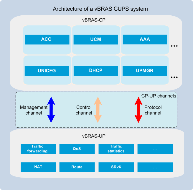
A vBRAS-CP provides access control and management. The following are its major components:
· ACC—Provides user access control. It processes access requests received from a vBRAS-UP for establishment of network connections for users, such as PPPoE and IPoE connections.
· UCM—Provides user session management and user policy management.
¡User session entry management—Generates and pushes user session entries to vBRAS-UPs. The vBRAS-UPs forward user traffic based on the session entries.
¡User policy management—Manages authentication, accounting, authorization, address allocation, and QoS policies.
· AAA—Works with the AAA server to provide authentication, authorization, and accounting for users.
· UNICFG—Configures BRAS services and automatically deploys the configuration to all its managed vBRAS-UPs.
· DHCP—Manages IP address resources.
· UPMGR—Manages vBRAS-UP Join and Exit events and the communication channels between the vBRAS-CP and vBRAS-UPs.
vBRAS-UPs are user policy enforcement points located at the edges of a Layer 3 network. They provide UP functionalities, including traffic forwarding, traffic statistics, and QoS policy enforcement.
Software architecture
vBRAS-CP
As shown in Figure 5, a vBRAS-CP contains CTRL-VMs, BRAS-VMs, FWD-VMs, and DB-VMs.
Figure 5 Software architecture of a vBRAS-CP

Table 2 Functionalities of the VMs in a vBRAS-UP
|
VM |
Functionalities |
Slot number assignment |
Remarks |
|
CTRL-VM |
· CP and UP management. · Configuration management. · Address allocation. · CP backup and recovery. · Elastic capacity scalability. |
1 and 2 |
Each vBRAS-CP has one CTRL-VM or two CTRL-VMs. Two CTRL-VMs automatically form a CTRL-VM group, with the group number fixed at 1. Each CTRL-VM group is one network element as a whole. In a CTRL-VM group, one CTRL-VM is the master, and the other is the standby node. The standby CTRL-VM backs up the master while the master is operating correctly and takes over when the master CTRL-VM fails. |
|
BRAS-VM |
BRAS-VMs are managed by the master CTRL-VM. They provide the following functionalities: · Remote interface management. · User management. · User access control. · AAA. · UP backup and recovery. |
97 to 224 |
Each vBRAS-CP has one or multiple BRAS-VMs. Every two BRAS-VMs with consecutive slot numbers form a BRAS-VM group, starting from slot 97. The BRAS-VM groups are numbered starting from 66. For example, the BRAS-VMs in slots 97 and 98 form BRAS-VM group 66. The BRAS-VMs in slots 99 and 100 form BRAS-VM group 67. Each BRAS-VM group is one network element as a whole. In a BRAS-VM group, one BRAS-VM is the master, and the other is the standby node. The standby BRAS-VM backs up the master while the master is operating correctly and takes over when the master BRAS-VM fails. |
|
FWD-VM |
FWD-VMs are managed by the master CTRL-VM. They provide the following functionalities: · Communication and packet forwarding between BRAS-VMs and UPs. · Packet forwarding between BRAS-VMs and external systems such as RADIUS servers and Web servers. |
5 and 6 (The value range from 7 to 96 is reserved for future use.) |
Each vBRAS-CP contains a maximum of two FWD-VMs. Each FWD-VM is a network element. They do not form a group as do the CTRL-VMs. |
|
DB-VM |
DB-VMs store data backed up from CTRL-VMs and BRAS-VMs. |
N/A |
You must deploy a minimum of four DB-VMs. The DB-VMs form a Codis cluster. |
vBRAS-UP
No special requirements are imposed on pUPs and vUPs in a centralized architecture. A distributed vUP contains MPU-VMs and LPU-VMs.
Figure 6 Software architecture of a distributed vBRAS-UP
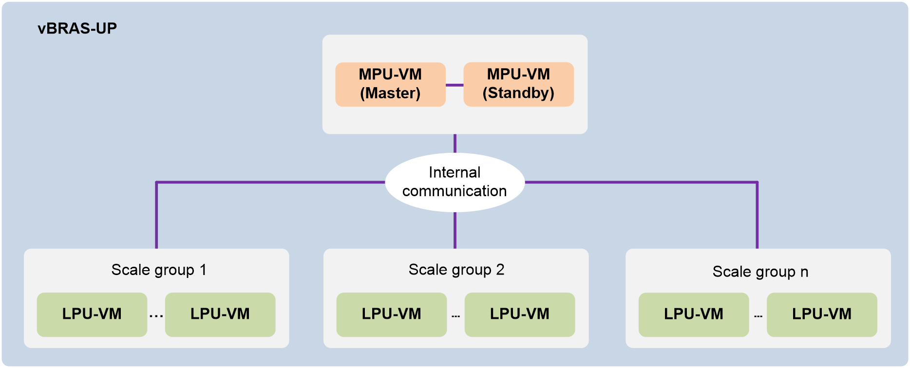
Table 3 Functionalities of the VMs in a vBRAS-UP
|
VM |
Functionalities |
Slot number assignment |
Remarks |
|
MPU-VM |
· Manages vUPs. · Provides control plane and management plane services of the vUP system. |
1 and 2 |
A vBRAS-UP has one MPU-VM or two MPU-VMs. One MPU-VM is the master, and the other is the standby node. The standby MPU-VM backs up the master while the master is operating correctly and takes over when the master MPU-VM fails. |
|
LPU-VM |
· Processes user services. · Forwards packets. |
5 to 36 |
A vBRAS-UP has one or multiple LPU-VMs. Multiple LPU-VMs form a scale group. For more information about scale groups, see vUP scaling in CP and UP Separation Configuration Guide. |
Operating mechanism
A vBRAS system allows dynamic PPPoE, L2TP, and IPoE access.
Figure 7 uses PPPoE as an example to describe how a vBRAS system establishes a network session for a user to access the network.
Figure 7 PPPoE access procedure
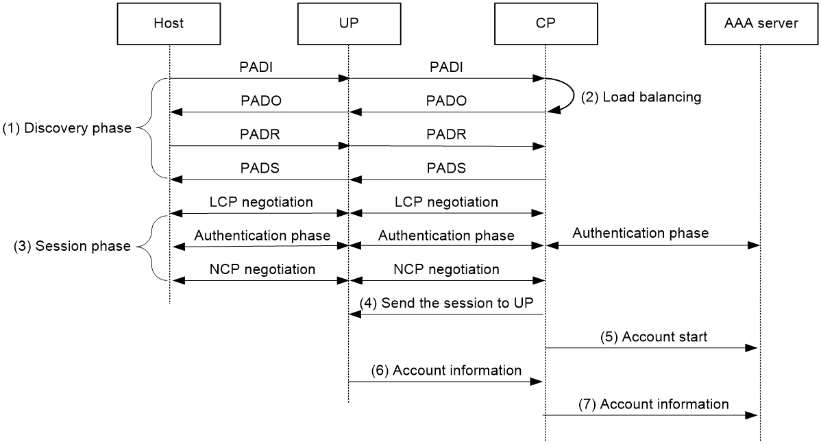
A vBRAS CUPS system uses the following procedure to provide network access services to a PPPoE user:
1. A UP receives a PPPoE discovery packet from a host. (The packets sent in the discovery phase are collectively called discovery packets.)
2. The UP sends the packet over the protocol channel (a VXLAN GPE tunnel) to the CP.
3. Upon receiving the discovery packet, the CP selects an access interface based on the load balancing UP backup profile.
4. The CP creates a PPPoE session and sends an authentication request to the AAA server. The request contains the user's username and password.
5. The CP takes action depending on the authentication result received from the AAA server.
¡ If the authentication fails, the CP notifies the UP to disconnect the user.
¡ If the authentication succeeds, the CP proceeds to the NCP negotiation phase.
6. If NCP negotiation succeeds, the CP pushes the PPPoE session entry to the UP over the control channel (for example, a CUSP channel).
7. The CP sends an accounting start request to the AAA server to start accounting for the user.
8. The UP collects user traffic statistics regularly and sends the statistics to the CP over the control channel.
9. The CP sends the traffic statistics to the AAA server for user accounting.
CUPS technology
CP-UP channels
About CP-UP channels
Before deploying user services, you must set up channels for each CP and UP pair for communication. The channels are used for exchanging protocol packets and deploying BRAS service configuration and entries.
As shown in Figure 8, you must set up a management channel, a control channel, and a protocol channel for a CP and UP pair.
Channel types
Management channel
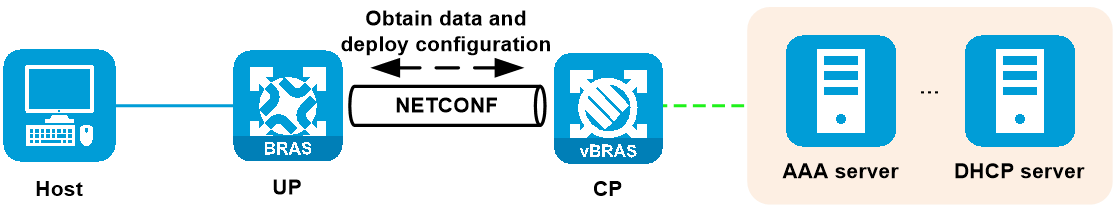
The management channel is a NETCONF connection for the CP to obtain data from the UP or configure the UP. For example, the CP can use this channel to create subinterfaces and issue BRAS services to the UP.
Figure 9 Management channel
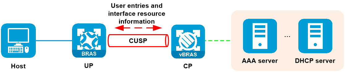
Control channel
The control channel is a Control-/User-plane Separation Protocol (CUSP) channel for control purposes. The CP deploys user entries (for example, PPPoE or IPoE user entries) and the UP obtains user entries or reports its interface resource information over this channel.
Figure 10 Control channel
Protocol channel
The protocol channel is a VXLAN Generic Protocol Extension (GPE) tunnel over which the CP and the UP exchange network service protocol packets, such as DHCP, ARP, and PPPoE protocol packets.
Figure 11 Protocol channel
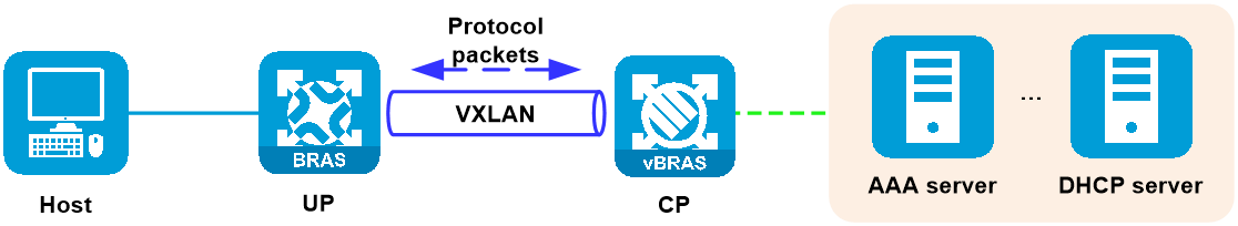
Operating mechanism
As shown in Figure 12, the CP and UP operate over the CP-UP channels as follows when a user comes online:
1. Establish a NETCONF management channel between the CP and UP.
2. The CP uses the NETCONF management channel to deploy configuration to the UP, such as CUSP, VXLAN, and BRAS service configuration.
3. The UP uses the configuration to establish the CUSP control channel and VXLAN protocol channel with the CP.
4. A user sends an online request to the UP.
5. The UP forwards the online request over the VXLAN protocol channel to the CP.
6. The CP processes the online request.
7. The CP interacts with the AAA and DHCP servers to complete user authentication and address allocation, and creates a user entry.
8. The CP deploys the user entry to the UP over the CUSP control channel.
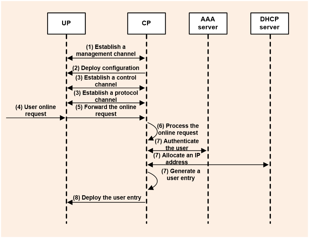
After the user comes online successfully, the UP guides user data packet forwarding based on the received user entry and periodically reports user traffic statistics to the CP over the CUSP control channel. Upon receiving user traffic statistics, the CP sends the statistics to the AAA server for user accounting.
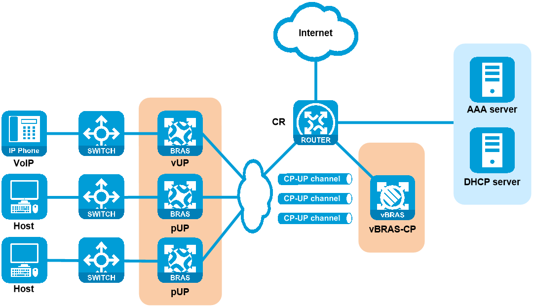
Typical networking
As shown in Figure 13, the vBRAS CUPS network uses a vBRAS-CP as the control plane to provide strong compute performance and a vUP and pUPs as the user plane.
· A vUP can provide high compute performance for small-size-flow and session-intensive services such as ITMS and VoIP.
· A pUP can provide high forwarding performance for large-size flow services such as broadband access and IPTV.
CPDR
Technical background
Facing unforeseeable events such as earthquakes and fires, local data backup cannot ensure no loss of backup data and cannot meet the carriers’ requirements for the availability, real-time performance, and security of service systems. To minimize enterprise losses due to backup data loss caused by unforeseeable events, the industry has introduced remote disaster recovery.
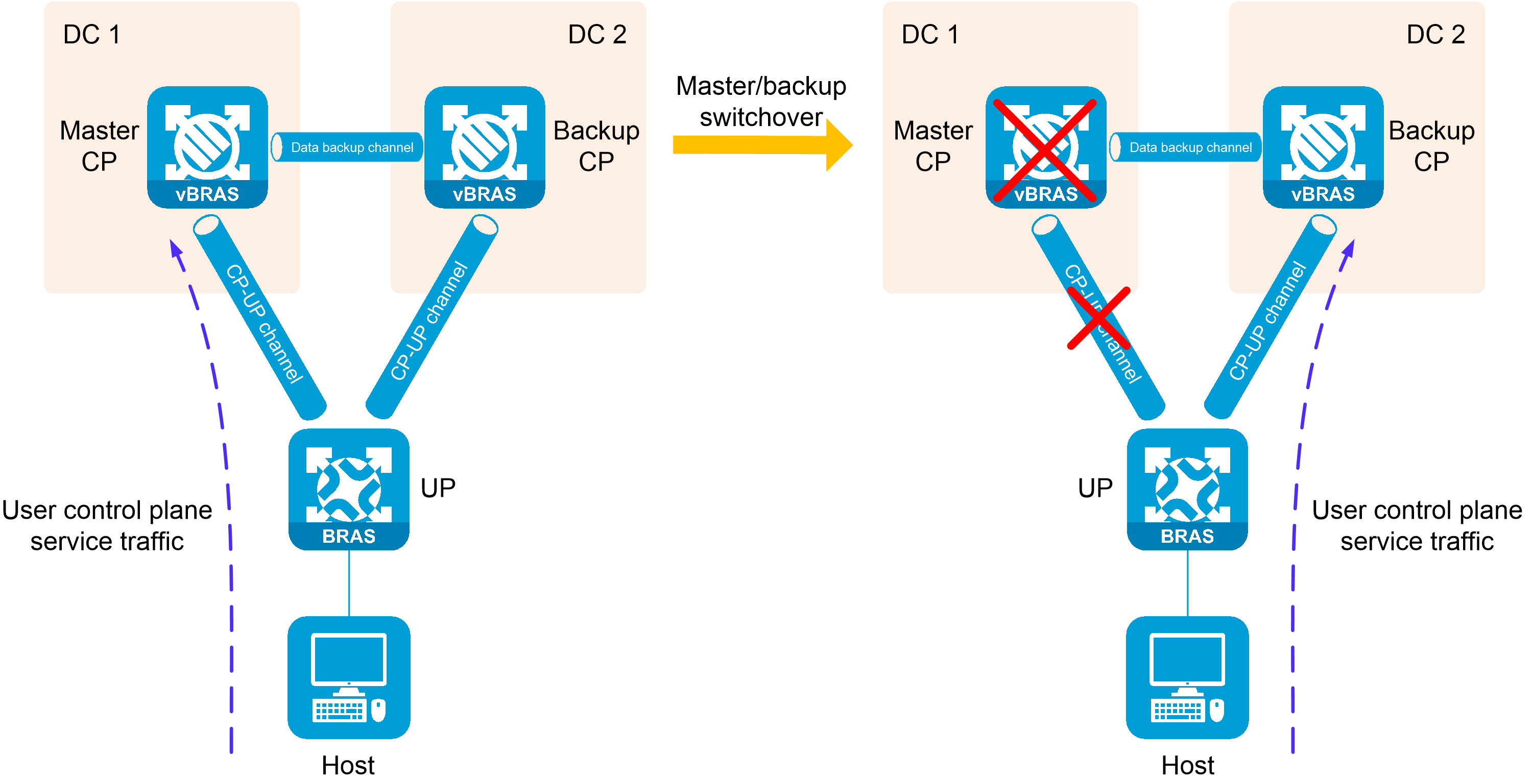
Control plane disaster recovery (CPDR) backs up data between the CPs in two data centers on a vBRAS CUPS network. When a DC suffers from a disaster, the other DC can rapidly take over user services.
Figure 14 CPDR functionality
Basic concepts
CPDR has the following basic concepts:
· CPDR group—CPs use CPDR groups to manage UPs. In a CPDR group pair, one group is the master and the other is the backup.
· Master and backup roles—A CP has the master role if the master CPDR group is created on it, and has a backup role if the back CPDR group is created on it. Only the master CP processes user services. A CPDR group can use the following types of roles:
¡ Configured role—Role configured by using the set role command. The configured role does not change if no configuration changes occur.
¡ Negotiated role—Role negotiated based on the specified settings. The negotiated role does not change if no configuration changes occur.
¡ Running role—Role that actually takes effect.
- When the heartbeat channel is correctly set up, the running role is the negotiated role.
- If the heartbeat channel is not set up because of network failure or incorrect IP address configuration for the CPDR channel, the CPDR groups cannot negotiate roles. In this case, the running role is the configured role.
The running role for a CPDR group might change upon a master/backup switchover or reconnection of the heartbeat channel. Unless otherwise specified, the master or backup role is represented by the running role of the CPDR group.
· CPDR group ID—A CPDR group is unique on a per CP basis. The master and backup CPs form a redundant pair with a CPDR group ID. The CPDR groups in the same redundant pair must have the same ID.
· CPDR group priority—Used in role election for CPDR groups. The CPDR group with a higher priority is the master.
· Faulty CU connections—Number of UPs with CUSP connection failures in a CPDR group.
· CU connection failure ratio—The CU connection failure ratio is calculated as follows:
¡ If a UP backup group has multiple UPs added to a CPDR group, value 1 is subtracted from total UPs in the CPDR group. Among a number of n such UP backup groups, if a number of m UP backup groups contain faulty UPs, the CU connection failure ratio = (faulty CU connections - m) / (total UPs in the CPDR group - n) × 100%.
¡ In other cases, the CU connection failure ratio = (faulty CU connections) / (total UPs in the CPDR group) × 100%.
· CPDR tunnel group—In the N:1 backup network, you must configure the parameters (such as the local and peer IP addresses) for establishing CPDR channels for each CPDR group based on CPDR tunnel group.
· CPDR tunnel group ID—As a best practice, bind the CPDR tunnel group with the same ID to the master and backup CPDR groups in a pair.
· Heartbeat channel—A TCP connection established between two CTRL-VMs for configuration negotiation, heartbeat channel detection, and CU connection state and CPDR group data synchronization.
· Data backup channel—A TCP connection established between two BRAS-VMs for backing up user data and service module data.
· Protection channel—A GRE tunnel established between two FWD-VMs. When the FWD-VM in the backup CPDR group receives a packet destined for the CPDR loopback interface, it forwards the packet to the FWD-VM in the master CPDR group through the protection channel. (A CPDR loopback interface is specified in the radius source-interface and web-auth source-interface commands.) This ensures that only the CP in the master CPDR group processes packets used for communication between the servers (such as RADIUS server and Web authentication server) and the CPs.
Benefits
When a fault occurs in the local disaster recovery backup center network, the remote disaster recovery backup center can quickly take over user services.
· Users are not aware of any network fault, which improves their network access experience.
· It improves the risk-resistance capability of carriers, which significantly enhances the network reliability.
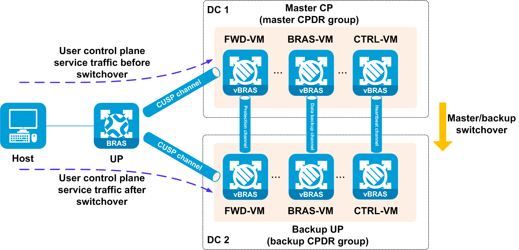
Operating mechanism
CPDR operates as follows:
1. CPDR establishes a heartbeat channel and multiple data backup channels between the master and backup CPs.
2. CPDR creates CPDR groups on the master and backup CPs, and adds UPs to the CPDR groups.
3. The UPs establish CUSP channels to the CPs of the master and backup CPDR groups, respectively.
4. The master and backup CPDR groups notify their roles through the CUSP channels to the UPs. The UPs take the CP in the master CPDR group as the master CP, and the CP in the backup CPDR group as the backup CP. The UPs exchange protocol and service packets with only the master CP.
5. The UPs deliver user packets to the master CP, and the master CP performs user authentication and authorization.
6. When the master CP is unavailable or the CU connection failure ratio meets the specified criteria, the backup CP takes over. The new master will recover user data from the backup CP or require the user to come online again, depending on the configured backup mode.
Figure 15 Operating mechanism
Backup modes
CPDR supports the hot backup and cold backup modes.
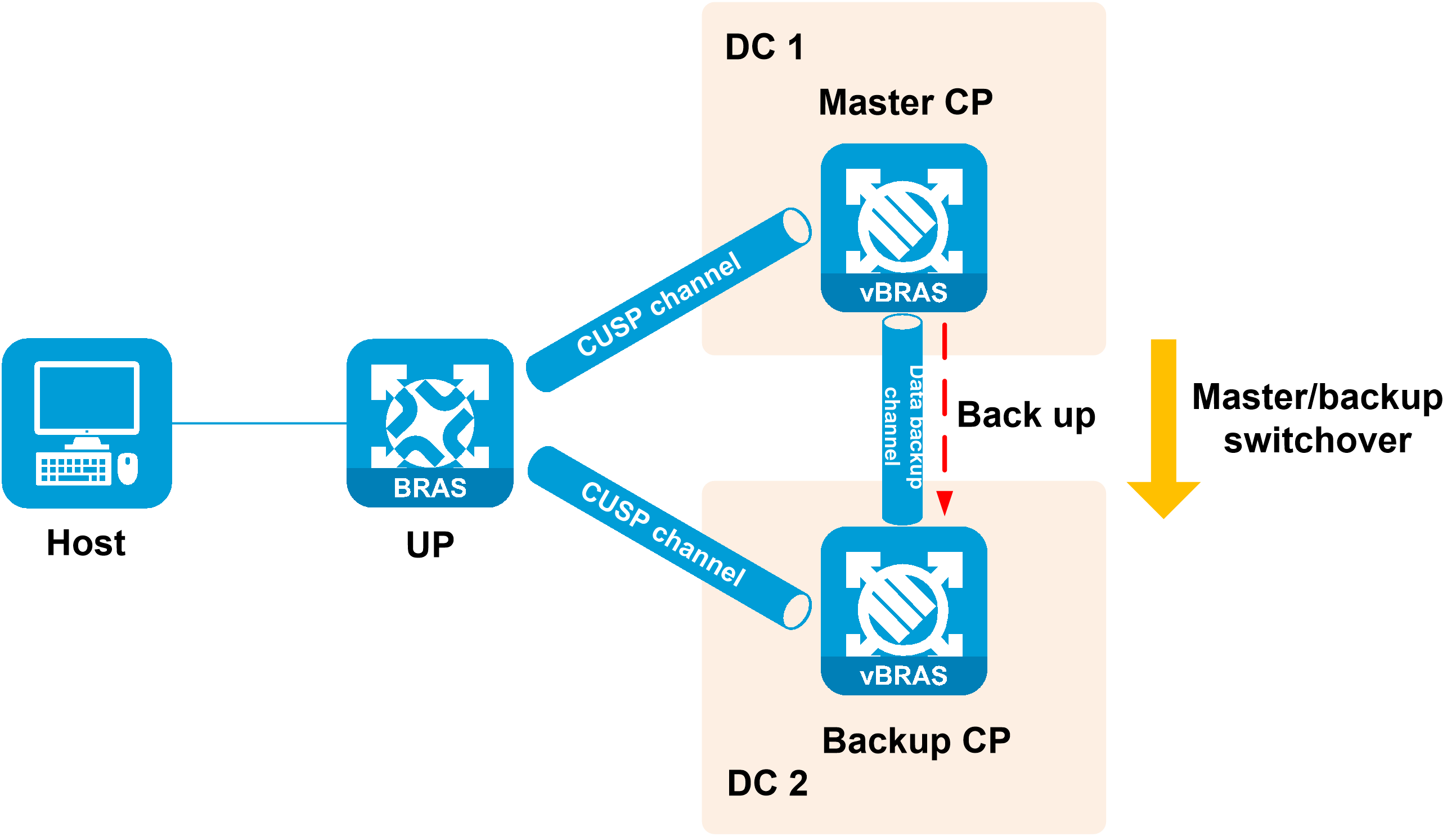
Hot backup mode
In hot backup mode, the master CP backs up user data to the backup CP through the data backup channel. When a master/backup switchover occurs, the new master CP quickly takes over user services based on the locally backed up user data. The users stay online after a master/backup switchover.
Figure 16 Hot backup mode
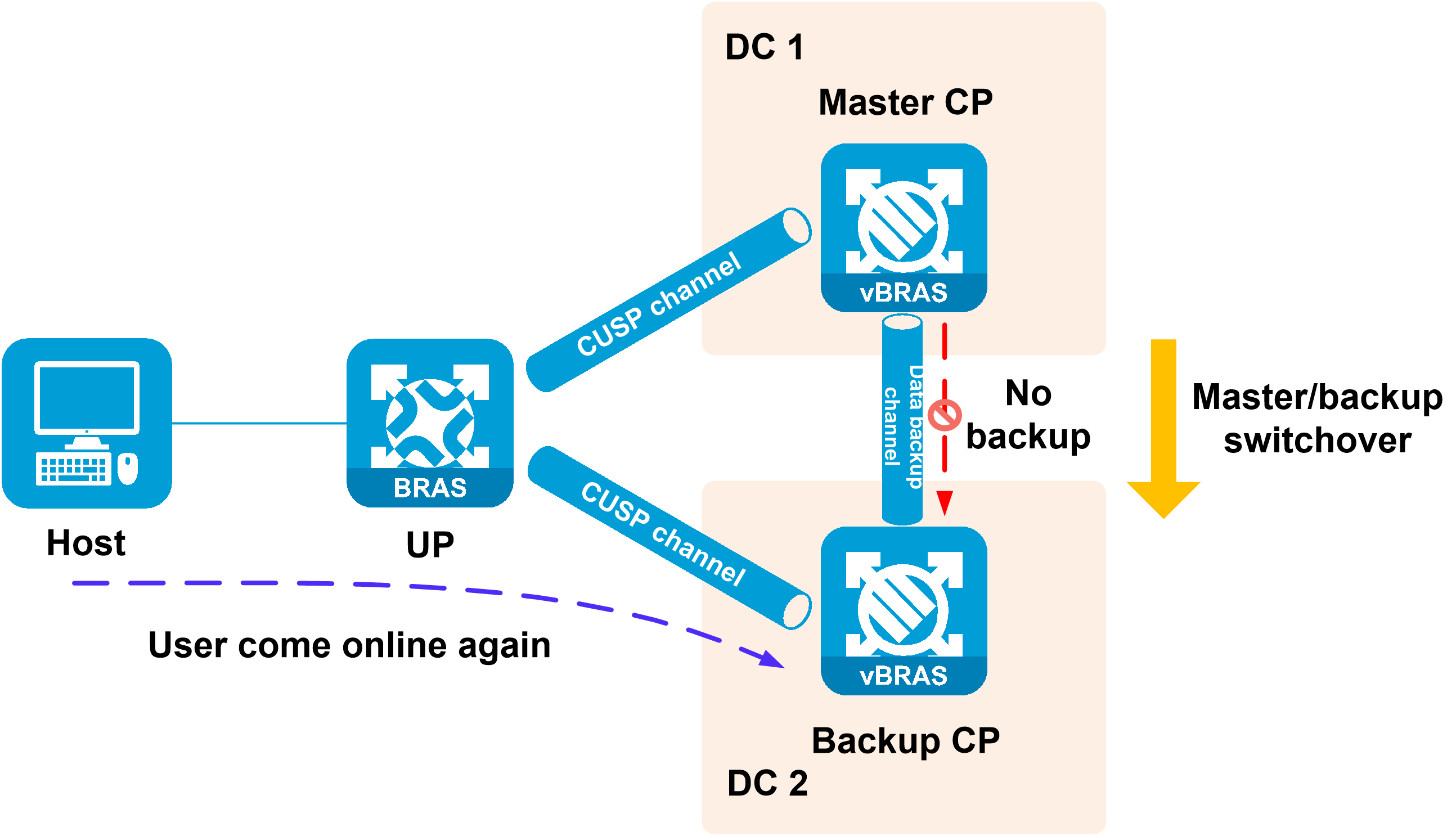
Cold backup mode
In cold backup mode, the master CP does not back up user data to the backup CP. The users must come online on the new CP again after a master/backup switchover.
Figure 17 Cold backup mode
Application modes
CPDR supports the load sharing, master/backup, and N:1 backup application modes.
Load sharing mode
In load sharing mode, both master and backup CPs work simultaneously. You create two pairs of CPDR groups for load sharing. Each CPDR group pair contains a master and a backup (with the same ID) and contains the same UPs. Different CPDR groups on the same CP have different master and backup roles. Different CPs only manage a part of the UP services, reducing the service pressure on a single point and improving the device usage.
In this mode, you must create two CPDR groups on both CPs, and assign different roles to the same CPDR group on the CPs to form a CPDR group pair. For example, if you assign the master role to a CPDR group on one CP, you must assign the backup role to the same CPDR group on the other CP.
Master/backup mode
In master/backup mode, the master CP works, and the backup CP backs up data. You create a pair of CPDR groups (a master and a backup) that contain the same UPs for backup. When a switchover occurs on the CP where the master CPDR group resides, the CP where the backup CPDR group resides can take over the user services on these UPs.
In this mode, you must create the same CPDR group (with the same name and ID) on the two CPs and assign the master role to the CPDR group on one CP and the backup role to the CPDR group on the other CP.
N:1 backup mode
In N:1 backup mode, N master CPs work simultaneously and one backup CP backs up data. You create N pairs of CPDR groups on N + 1 CPs. Each CPDR group pair contains a master and a backup (with the same ID) and contains the same UPs. Deploy N master CPDR groups to N master CPs and N backup CPDR groups to one backup CP. This deployment enables multiple data centers to share one backup data center. For example, you can specify CP 1 and CP 2 as master CPs and CP 3 as the backup CP to implement 2:1 backup as follows:
· On CP 1, create CPDR group with name group1 and ID 1, and assign the master role to the CPDR group.
· On CP 2, create CPDR group with name group2 and ID 2, and assign the master role to the CPDR group.
· On CP 3, create CPDR group with name group1 and ID 1, and assign the backup role to the CPDR group. Create CPDR group with name group2 and ID 2, and assign the backup role to the CPDR group.
Role switchover modes
CPDR supports automatic role switchover and manual role switchover through a command. By default, a CPDR group does not automatically perform a master/backup switchover upon failures. To perform a switchover, you must execute the switchover force command. For user service continuity, configure automatic role switchover upon CPDR group failure on both the master and backup CPDR groups to enable the backup to automatically take over when the master fails.
Automatic role switchover
Automatic role switchover upon CPDR group failure
· About automatic role switchover upon CPDR group failure
By default, automatic role switchover upon CPDR group failure is disabled. A CPDR group does not automatically perform a master/backup switchover upon failures.
After you enable automatic role switchover upon CPDR group failure, the backup CPDR group takes over as the master if the following criteria are still met after the specified switchover delay timer expires.
¡ The CU connection failure ratio on the master CPDR group reaches or exceeds the specified threshold.
¡ The CU connection failure ratio on the backup CPDR group is lower than that on the master CPDR group.
· Commands
¡ Use switchover auto enable to enable automatic role switchover upon CPDR group failure. By default, this feature is disabled.
¡ Use switchover control-tunnel-down threshold to configure the CU connection failure ratio threshold to trigger switchover. The default setting is 100%.
¡ Use switchover control-tunnel-down delay to configure the delay timer for switchover upon CU connection failure. The default setting is 30 seconds.
Automatic role switchover upon failure recovery of the original master
· About automatic role switchover upon failure recovery of the original master
By default, a backup CPDR group (original master) does not automatically switch back to the master role when the failure is recovered. To perform a switchover, configure this mode on the original master to enable it to automatically switch back to master upon failure recovery.
With this mode configured, the backup CPDR group starts a delay timer when the CU connection failure ratio on the backup drops to or below the failure recovery threshold. When the delay timer expires, the backup CPDR group sends a switchover request to the peer if the criterion is still met.
¡ If the backup CPDR group receives a response that acknowledges the request within 15 seconds (no configurable), it starts switchover to master. The peer starts switchover to backup.
¡ If the backup CPDR group receives a response that denies the request within 15 seconds, it starts the delay timer again. When the delay timer expires, the backup CPDR group sends a switchover request to the peer again if the switchover criterion is still met.
¡ If the backup CPDR group receives no response within 15 seconds, it starts switchover to master.
· Commands
¡ Use failure-recovery auto enable to enable automatic role switchover upon failure recovery of the original master. By default, this feature is disabled.
¡ Use failure-recovery threshold to configure the CU connection failure ratio threshold to trigger switchover on the original master. The default setting is 0%.
¡ Use failure-recovery delay to configure the delay timer for switchover upon failure recovery on the original master. The default setting is 1800 seconds.
Manual role switchover
About manual role switchover
By default, a CPDR group does not automatically perform a master/backup switchover upon failures. To manually perform a switchover, execute the switchover force command.
After the original master recovers from a failure, you can use the command to perform a manual role switchover. The command is not saved to the configuration file.
You can perform manual role switchover on the master or backup CP.
· After you execute the switchover force to-backup command on the master CP, if the CPDR channels are normal, the master CP switches to backup, and the backup CP switches to master. If the CPDR channels are abnormal, role switchover is not allowed.
· After you execute the switchover force to-master command on the backup CP, the backup CP switches to master (ignoring the heartbeat channel state) and increases the priority. The master CP switches to backup (after the heartbeat channel recovers from a failure).
· After you execute the switchover force to-master command on the master CP, the master CP keeps its role unchanged and increases the priority by 1.
· After you execute the switchover force to-backup command on the backup CP, the backup CP retains its role and priority.
Manual switchover to the backup role
When you execute the switchover force to-backup command, the system identifies whether the current CPDR group is stable:
· If the CPDR group is stable, the system identifies the running role of the current CTRL-VM.
¡ If the running role is the master CP, the system identifies whether a heartbeat channel is established.
- If a heartbeat channel has been established, the system notifies the backup CP of role switchover.
- If no heartbeat channel is established, the system forcibly switches the master CP to backup.
¡ If the running role is the backup CP, its role remains unchanged.
· If the CPDR group is unstable, manual role switchover is not allowed. The system will prompt a command deployment error.
Manual switchover to the master role
When you execute the switchover force to-master command, the system identifies whether the current CPDR group is stable:
· If the CPDR group is stable, the system identifies the running role of the current CTRL-VM.
¡ If the running role is the master CP, its role remains unchanged and its priority increases. The new priority is deployed to the BRAS-VM.
¡ If the running role is the backup CP, the system forcibly switches the backup CP to master and the peer master CP to backup.
· If the CPDR group is unstable, manual role switchover is not allowed.
Switchover delay timer
Delay timer for automatic role switchover upon CPDR group failure
· About the delay timer for automatic role switchover upon CPDR group failure
Configure the delay timer for the backup CPDR group to be switched to master when it detects the master CPDR group is faulty. After you enable automatic role switchover upon CPDR group failure, the backup CPDR group takes over as the master if the following criteria are still met after the specified switchover delay timer expires.
¡ The CU connection failure ratio on the master CPDR group reaches or exceeds the specified threshold.
¡ The CU connection failure ratio on the backup CPDR group is lower than that on the master CPDR group.
· Commands
Use switchover control-tunnel-down delay to configure the delay timer for switchover upon CU connection failure. The default setting is 30 seconds.
Delay timer for automatic role switchover upon failure recovery of the original master
· About the delay timer for automatic role switchover upon failure recovery of the original master
After you enable automatic role switchover upon failure recovery of the original master, the backup CPDR group starts a delay timer when the CU connection failure ratio on the backup drops to or below the failure recovery threshold. When the delay timer expires, the backup CPDR group sends a switchover request to the peer if the criterion is still met.
· Commands
Use the failure-recovery delay command to configure the delay timer for switchover upon failure recovery of the original master. The default setting is 1800 seconds.
UP backup
Background
In a vBRAS CP and UP separation (CUPS) scenario, UPs implement forwarding plane functions, such as user traffic forwarding and traffic control. Users access the network and come online through UPs. When a UP fails or a link between the user and the UP fails, service are interrupted for all users that come online through this UP.
You can add multiple UPs to a UP backup group. The interfaces on the UPs form a backup or load sharing relationship. This provides device-level redundancy protection and enhances network availability.
Figure 18 UP backup functionality
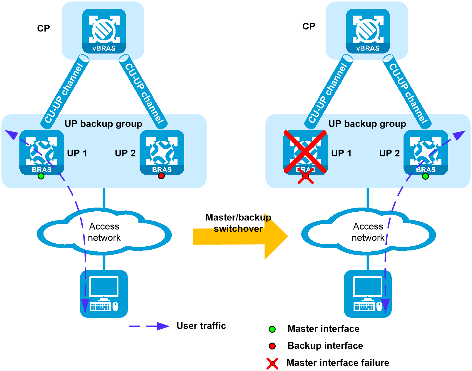
Basic concepts
UP backup performs backup based on the interface granularity, providing availability protection for user services at the UP side. The basic concepts for the UP backup feature are as follows:
· UP backup group—A UP backup group contains multiple UPs for interface-based user service backup.
· UP backup profile—You can create UP backup profiles in corresponding UP backup modes based on service demands, and specify the master and backup interfaces for the UP backup profiles.
· Master interface—The interface that carries user services.
· Backup interface—The interface used as backup for the master interface. When the master interface fails, the backup interface takes over to forward user traffic.
· Master UP—The UP where the master interface resides in the associated UP backup profile.
· Backup UP—The UP where the backup interface resides in the associated UP backup profile.
· Switchover—When the master interface fails, the backup interface takes over to forward user traffic.
· Switch-back—When the master interface recovers, traffic switches back to the master interface.
Operating mechanism
A CP manages multiple UPs, and performs backup between interfaces on different UPs. When the master UP or interface fails, the CP instructs the backup UP or interface to immediately take over to ensure uninterrupted user traffic and reduce the impact on services caused by device failure.
Backup modes
Based on application scenarios, UP backup supports 1:1 hot standby mode, N:1 warm standby mode, 1:N warm load balancing mode, and load balancing mode.
1:1 hot standby mode
In 1:1 hot standby mode, a master interface and a backup interface back up each other. The CP device issues session information to both the master and backup interfaces. When the master interface fails, the backup UP immediately takes over to ensure user service continuity. This mode is applicable to the scenarios with relatively high availability requirements.
N:1 warm standby mode
In N:1 warm standby mode, multiple master interfaces use one backup interface for backup. The master interfaces load share services. The CP issues the user session information to only the master UP. When a master interface or master UP fails, the CP issues session information to the original backup UP. The original backup UP then takes over the user services with short user service interruption time.
The following warm standby modes are available:
· Common warm standby mode—The backup interface provides backup services only for the master interface that fails first. If an additional master interface fails, no more backup interfaces are available, and users cannot come online through this master interface.
· Enhanced warm standby mode—The backup interface can provide backup services for multiple master interfaces to enhance service availability.
1:N warm load balancing mode
1:N warm load balancing mode contains a number of N + 1 (1 ≤ N ≤ 15) master interfaces and does not contain any backup interfaces. A master interface forms a backup relationship with each of the N master interfaces. Each pair of master interfaces (a primary master interface and a secondary master interface) corresponds to a unique virtual MAC address automatically generated by the system. A number of N + 1 master interfaces can form a total of N × (N + 1) backup pairs and N × (N + 1) virtual MAC addresses.
When a user comes online, the CP selects the master interface with the fewest online users from the UP backup profile as the primary master. If multiple interfaces have the fewest online users, the CP selects one of them based on specific principles as the primary master. When any master interface fails, user traffic on the master interface are automatically load shared among the other N interfaces based on the virtual MAC address.
Load balancing mode
This mode contains N master interfaces and does not contain any backup interfaces. The master interfaces load share services. When a master UP or master UP fails, users coming online through this interface will not switch to other master interfaces. Instead, the users will be forced offline. Then the users can come online again through another master interface without any faults.
Fault detection
In the vBRAS CUPS scenario, the system must perform fault detection for master/backup switchover to implement UP backup. UP backup supports fault detection mechanisms based on user-side interface state, network-side interface state, and CUSP state.
The CP will receive fault information reported through different detection methods as configured, and instructs master/backup switchover based on the information.
Fault detection based on user-side interface state
In the vBRAS CUPS scenario, the CP issues a tag to the user-side interface used when users come online to identify the interface. The up/down state of the user-side interface can then be reported to the CP through the CUSP protocol. When the user-side interface fails, the master interface state changes to down. The UP then reports the fault information to the CP to trigger master/backup switchover.
Fault detection based on network-side interface state
In the vBRAS CUPS scenario, the UP uses the Track feature to monitor the up/down state of the network-side interface. When a network-side interface failure occurs, Track notifies the track entry status to the UP, which then reports the failure information to CP, triggering master/backup switchover.
You can configure fault detection based on network-side interface state as needed.
Fault detection based on CUSP connection state
In the vBRAS CUPS scenario, the CP performs master/backup UP or interface switchover based on the CUSP connection state. When the CUSP connection between the CP and a UP recovers, the CP performs master/backup switchover for the UP or interface on the UP after a period of time upon the recovery. The CP can detect the CUSP connection state without requiring report from the UP.
If CUSP state-based detection is configured, link flapping might result in frequent master/backup switchovers. You can configure the switchover delay upon CUSP channel failure and CUSP channel failure recovery. This configuration prevents the CP to frequently perform master/backup UP or interface switchovers when link flapping occurs between the CP and UP. Too short a switchover delay might cause frequent master/backup switchovers, which affect the normal operation of UP backup. Too long a switchover delay might cause late master/backup switchovers when a CUSP channel is interrupted, which causes long traffic interruption time.
You can configure fault detection based on CUSP connection state as needed. You can associate the CUSP connection with Bidirectional Forwarding Detection (BFD) based on network requirements. This configuration enables the CUSP controller to create a BFD session for a new CUSP connection to fast detect CUSP connection faults.
Fault detection between UPs
In a vBRAS CUPS network, the CUSP connection between UP and CP passes through multiple levels of devices. If the CUSP connection state is abnormal but the UP is operating correctly, a master/backup switchover will be performed, resulting in a waste of resources. The CUSP channel state cannot be used to determine UP failure.
To resolve the issue that an actual UP failure cannot be reported to the CP because the CUSP connection is disconnected, you can configure a UP to use Track to monitor the network-side link state on another UP in the same UP backup group.
Associate the Track module on the monitoring UP with the Track module on the monitored UP, and use Track to monitor network-side interface failures on the monitored UP. When a network-side interface failure occurs on the monitored UP, Track notifies the track entry status to the monitoring UP, which then reports the failure information to CP.
Upon receiving the failure information, the CP instructs the master/backup interface switchover on the UP where the faulty interface resides based on the state of the CUSP connection between the CP and UP. If the CP detects that the CUSP connection with the monitored UP is disconnected, a master/backup switchover is performed. If the CP does not detect the CUSP connection failure, the master/backup switchover is not performed. Fault detection between UPs applies to the scenario where the network-side interface shares the same link egress as the CUSP protocol.
Switchover upon failure
This document takes the 1:2 warm standby mode as an example to illustrate the switchover processes for UP backup in different service scenarios.
Switchover upon failure in the CGN service scenario
Carrier Grade NAT (CGN) is also called large-scale NAT (LSN). Traditionally, NAT is typically deployed on the Customer Premises Equipment (CPE), which translates a small number of user IP addresses. You can deploy CGN to the ISP network by inserting a CGN module into a device such as (BRAS). This implements IP address translation for a large number of users, greatly improving the number of supported concurrent users, performance, and source tracking.
The CGN service adopts the hot standby deployment mode within the chassis and cold backup deployment mode between chassis. The CGN service and the master/backup relationship of UPs do not affect each other. When a CGN service or UP master/backup switchover occurs, users remain online. The CGN service will re-apply for a public IP address for users.
In the CGN service scenario, a master/backup switchover is triggered upon user-side interface failure of the UP, network-side interface failure of the UP, UP failure, or CGN module failure.
1. User-side interface failure of the UP
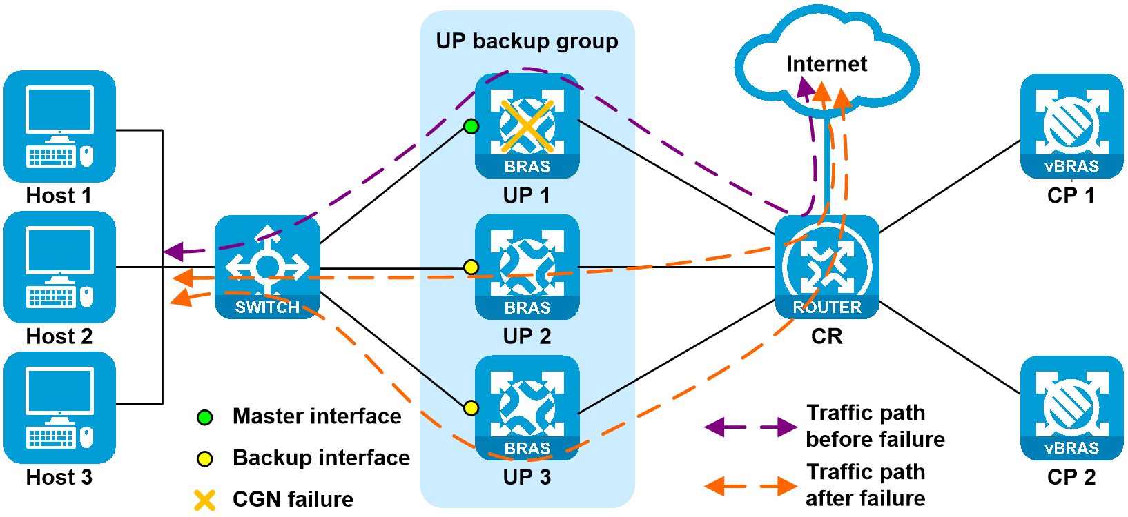
As shown in Figure 19, a network-side interface failure on UP 1 triggers a master/backup switchover for the UP. The CGN service is not backed up and switches over with the UP. User traffic on UP 1 is then load shared among UP 2 and UP 3. After UP switchover, the CGN service automatically re-applies a public IP address on the new UP for users that switch over to the new UP.
Figure 19 User-side interface of the UP

2. UP failure or network-side interface failure
As shown in Figure 20, failure of UP 1 or a network-side interface failure on UP 1 triggers a master/backup switchover for the UP. The CGN service is not backed up and switches over with the UP. User traffic on UP 1 is then load shared among UP 2 and UP 3. After UP switchover, the CGN service automatically re-applies a public IP address on the new UP for users that switch over to the new UP.
Figure 20 UP failure or network-side interface failure

3. CGN module failure
As shown in Figure 21, if only one CGN module fails on UP 1, switchover is not performed. If both CGN modules fail, a network-side failure is triggered and reported to the CP, and a master/backup switchover is performed for the UP. The CGN service is not backed up and switches over with the UP. User traffic on UP 1 is then load shared among UP 2 and UP 3. After UP switchover, the CGN service automatically re-applies a public IP address on the new UP for users that switch over to the new UP.
Switchover upon failure in the L2TP service scenario
Layer 2 Tunneling Protocol (L2TP) establishes point-to-point L2TP tunnels over a public network (such as the Internet) to transfer encapsulated Point-to-Point Protocol (PPP) data frames. This enables remote users (such as offsite enterprise branch users and business travelers) to use PPP to access the public network and then communicate with the enterprise's internal network through the L2TP tunnel. This facilitates secure, cost-effective, and efficient remote access to a private enterprise network for remote users.
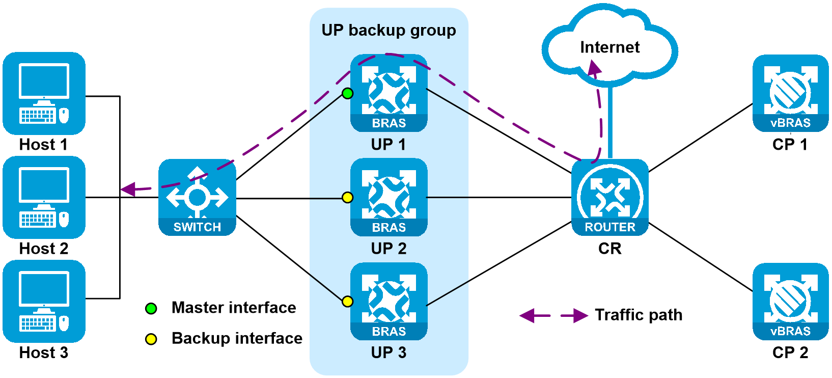
Currently, L2TP services are deployed without using the backup mechanism. As shown in Figure 22, the paths for both uplink and downlink traffic for users are consistent, and no switchover bypass situations exist.
Figure 22 L2TP user traffic processing
In the L2TP service scenario, when a user-side interface failure of the UP, network-side interface failure of the UP, or UP failure occurs, users go offline because L2TP services are not backed up. They can come online through dial-up again. In earlier versions of the vBRAS CUPS environment, master/backup switchover in the L2TP service scenario requires using a protection tunnel. The mechanism is different from the implementation described in this document. In this document, each UP uses a fixed loopback interface address to communicate with the LNS. This facilitates deployment because no backup mechanism is used and no protection tunnel is required to be configured.
1. User-side interface failure of the UP
As shown in Figure 23, the user-side interface on UP 1 is faulty, the CUSP control channel is operating correctly, and the service link is disconnected. UP 1 reports the fault information to CP through the CUSP protocol. CP then informs the UP to perform master/backup switchover. Upon detecting no L2TP service backup configuration on UP 1, CP forces users on UP 1 to go offline. Subsequent offline users can dial up again to come online through UP 2 and UP 3 in a load-balanced manner.
Figure 23 User-side interface failure of the UP

When the failure is recovered, UP 1 reports the failure recovery information to CP through the CUSP protocol. CP informs UP 1 to switch to master, and then informs UP 2 and UP 3 to switch to backup. After the failure is recovered, upon detecting no L2TP service backup configuration on UP 2 and UP 3, CP forces users on UP 2 and UP 3 to go offline. Subsequent offline users can dial up again to come online through UP 1. Both uplink and downlink user traffic switch back to the links attached to UP 1.
2. UP failure or network-side interface failure
As shown in Figure 24, when UP 1 or the network-side interface on UP 1 is faulty, both the CUSP control channel and the service link are disconnected. CP detects the CUSP connection state anomaly and informs the UP to perform master/backup switchover. Upon detecting no L2TP service backup configuration on UP 1, CP forces users on UP 1 to go offline. Subsequent offline users can dial up again to come online through UP 2 and UP 3 in a load-balanced manner.
Figure 24 UP failure or network-side interface failure

When the failure is recovered, CP detects that the CUSP connection is restored, and then restores the connection to the UP. After the CP-to-UP connection failure is recovered, CP informs UP 1 to switch to master, and then informs UP 2 and UP 3 to switch to backup. After the failure is recovered, upon detecting no L2TP service backup configuration on UP 2 and UP 3, CP forces users on UP 2 and UP 3 to go offline. Subsequent offline users can dial up again to come online through UP 1. Both uplink and downlink user traffic switches back to the links attached to UP 1.
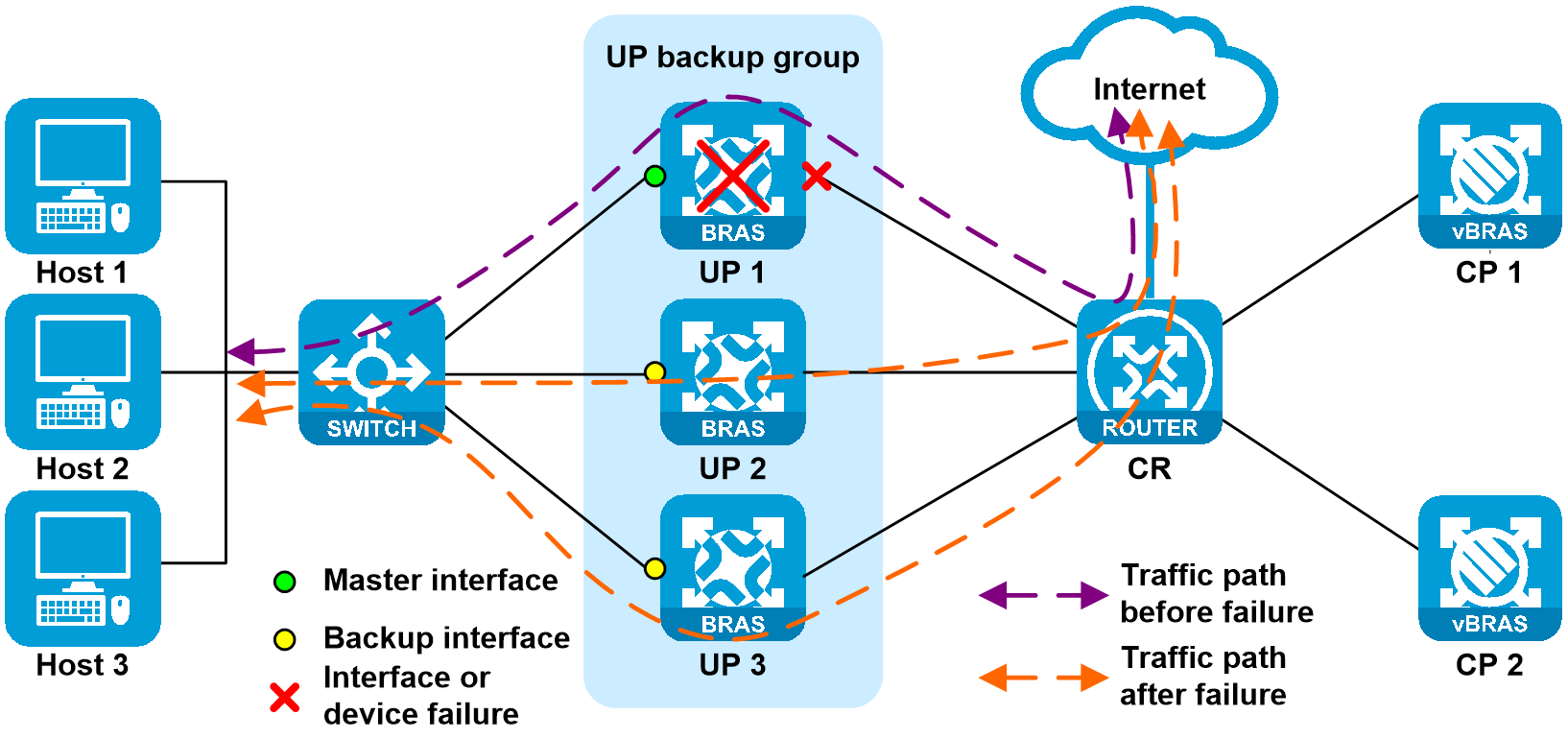
Switchover upon failure in the other service scenarios
In other scenarios, switchover upon failure is not associated with protocol tunnels. Instead, it is associated with only the priority of user routes. User traffic is switched according to route switchover.
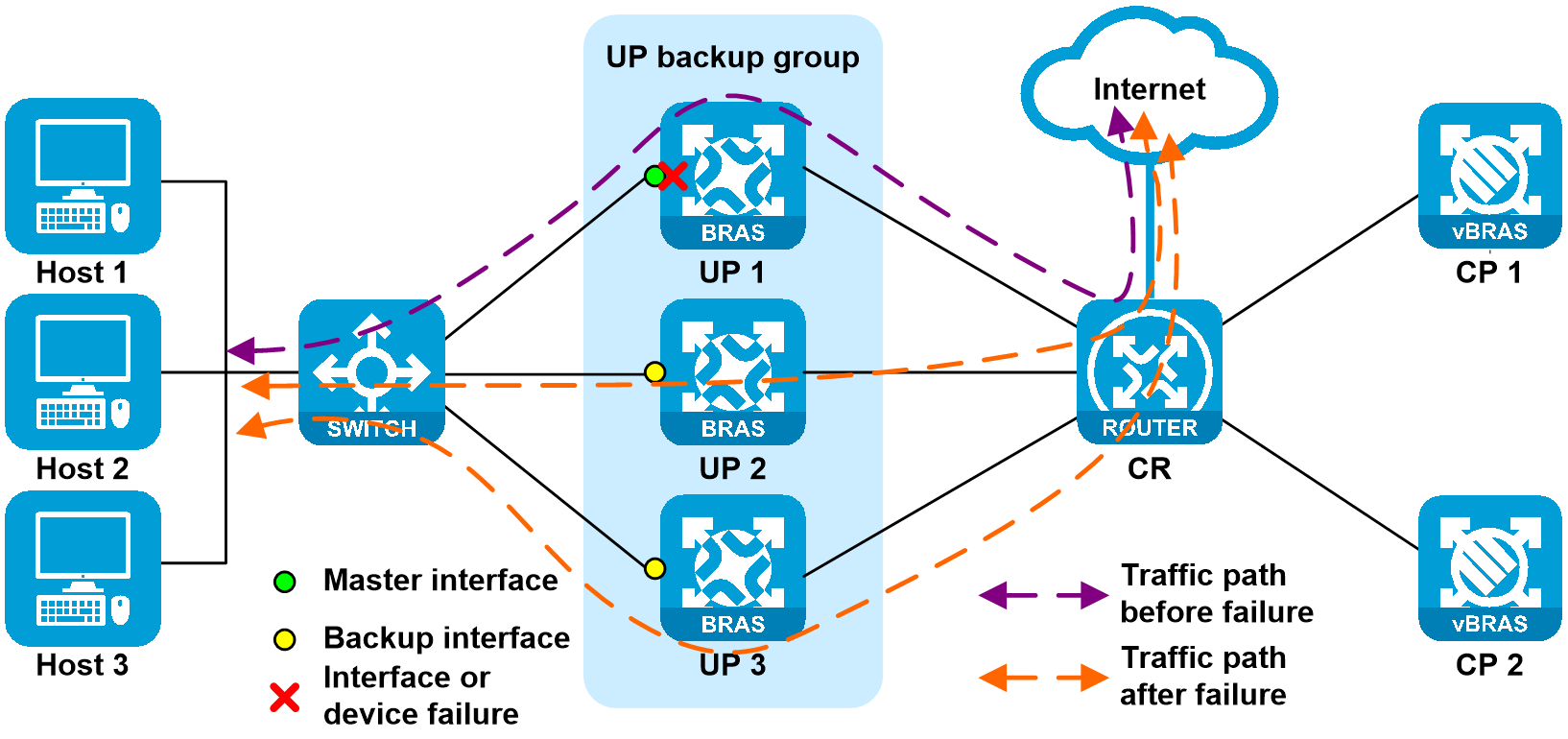
1. User-side interface failure of the UP
As shown in Figure 23, the user-side interface on UP 1 is faulty, the CUSP control channel is operating correctly, and the service link is disconnected. UP 1 reports the fault information to CP through the CUSP protocol. CP then informs the UP to perform master/backup switchover. The priority for the route issued to UP 1 by CP decreases (the route cost is changed from 10 to 20), and priority for the routes issued to UP 2 and UP 3 increases (the route cost is changed from 20 to 9). When a failure occurs, CR learns the routes with higher priority (with cost 9). After route convergence, both uplink and downlink traffic are load-balanced to the links attached to UP 2 and UP 3.
Figure 25 User-side interface of the UP
When the failure is recovered, UP 1 reports the failure recovery information to CP through the CUSP protocol. CP informs UP 1 to switch to master, and then informs UP 2 and UP 3 to switch to backup, reducing packet loss during switch-back. In the switch-back process, the route issued to UP 1 by CP increases (the route cost is changed from 20 to 10), and priority for the routes issued to UP 2 and UP 3 decreases (the route cost is changed from 9 to 20). When the failure is recovered, CR learns the routes with higher priority (with cost 10). After route convergence, both uplink and downlink traffic switch back to the links attached to UP 1.
2. UP failure or network-side interface failure
As shown in Figure 26, when UP 1 or the network-side interface on UP 1 is faulty, both the CUSP control channel and the service link are disconnected. Upon detecting the CUSP connection state anomaly and receiving the track entry status indicating the interface failure, CP informs the UP to perform master/backup switchover. The priority for the route issued to UP 1 by CP decreases (the route cost is changed from 10 to 20), and priority for the routes issued to UP 2 and UP 3 increases (the route cost is changed from 20 to 9). When a failure occurs, CR learns the routes with higher priority (with cost 9). After route convergence, both uplink and downlink traffic are load-balanced to the links attached to UP 2 and UP 3.
Figure 26 UP failure or network-side interface failure
When the failure is recovered, CP detects that the CUSP connection is restored, and then restores the connection to the UP. After the CP-to-UP connection failure is recovered, CP informs UP 1 to switch to master, and then informs UP 2 and UP 3 to switch to backup, reducing packet loss during switch-back. In the switch-back process, the route issued to UP 1 by CP increases (the route cost is changed from 20 to 10), and priority for the routes issued to UP 2 and UP 3 decreases (the route cost is changed from 9 to 20). When the failure is recovered, CR learns the routes with higher priority (with cost 10). After route convergence, both uplink and downlink traffic switch back to the links attached to UP 1.
Configuring key modules
Configuring the CUSP controller
In a CUPS network, the CUSP control channel includes the following basic components:
· CUSP controller—The server of the CUSP protocol, located on the CP.
· CUSP agent—The client of the CUSP protocol, located on the UP.
Configuring the listening IP address for the CUSP controller
Commands
Use listening-ip { ipv4-address | ipv6 ipv6-address } [ vpn-instance vpn-instance-name ] to configure the listening IP for a CUSP controller.
Usage guidelines
For the CUSP controller to act as a server and wait for CUSP connection requests from CUSP clients, you must specify a listening IP address for the CUSP controller.
If you execute this command multiple times, the most recent configuration takes effect.
This command is supported only on CPs.
Examples
cusp controller //Enter CUSP controller view.
listening-ip 180.96.185.8 vpn-instance CP2UP_L3VPN_H3C //Configure the listening IP for the CUSP controller.
Configuring a CUSP agent
Commands
Use agent agent-name to create a Control-/User-plane Separation Protocol (CUSP) agent on a CUSP controller and enter its view, or enter the view of an existing CUSP agent.
Usage guidelines
Recommended configuration
To facilitate CUSP agent management on a CUSP controller, as a best practice, use this command to specify a CUSP agent name the same as the CUSP agent name configured on the corresponding UP.
Restrictions and guidelines
· You can execute this command multiple times to add multiple CUSP agents. On a CUSP controller, you can add up to 1024 CUSP agents.
· This command is supported only on CPs.
Examples
cusp controller //Enter CUSP controller view.
agent bras_up1 // Create CUSP agent bras_up1 on the CUSP controller and enter its view.
agent-ip 2.1.1.101 // Specify the IP address of a CUSP agent to which a CUSP controller can connect.
Configuring the NETCONF client
In a CUPS network, the CP acts as a NETCONF client, and the UP acts as a NETCONF server.
You can configure NETCONF parameters for a management channel in NETCONF client view on a CP. After a management channel is set up between the CP and a UP, the CP can configure and manage the UP.
Configuring a NETCONF connection profile
Commands
Use connection connection-name to create a NETCONF connection profile (which is used for connecting to a remote UP) and enter its view, or enter the view of an existing NETCONF connection profile.
Usage guidelines
Before a NETCONF over SSH connection is set up between a CP and a UP, you must configure NETCONF connection setup parameters in each NETCONF connection profile to be bound to the UP.
You cannot modify settings of a NETCONF connection profile that has been bound to a UP.
Examples
netconf-client // Enter NETCONF client view.
source-address 180.96.185.8 //Specify the source IP address used for setting up a NETCONF connection to a UP.
connection bras_up1 //Create a NETCONF connection profile named bras_up1 (which is used for connecting to a remote UP) and enter its view.
user-name admin password simple 123 //Specify the username and password used for setting up a NETCONF connection to a UP.
destination-address 2.1.1.101 vpn-instance CP2UP_L3VPN_H3C //Specify the IP address of a UP to which a NETCONF connection will be set up.
Configuring a UP management instance
Configuring the parameters for the protocol channel between the CP and UP
Commands
Use protocol-tunnel vxlan vxlan-id source { ipv4-address | ipv6 ipv6-address } destination { ipv4-address | ipv6 ipv6-address } [ vpn-instance vpn-instance-name ] to configure parameters for the protocol channel between a UP and the CP.
Usage guidelines
Operating mechanism
A VXLAN tunnel is established between the CP and UP and used as the protocol channel for exchanging protocol packets, such as ARP, IP, and DHCP protocol packets.
When you execute this command, make sure the source IP specified is the destination IP of the protocol channel on the UP, and the destination IP specified is the source IP of the protocol channel on the UP.
Restrictions and guidelines
· The VXLAN tunnels on the CP and UP must have the same VXLAN ID.
· If you execute this command multiple times with the same VXLAN ID, source IP address, and destination IP address, the most recent configuration takes effect.
· Different UPs correspond to different VXLAN tunnels. The source IP address and destination IP address of each VXLAN tunnel must be unique. That is, a source IP address and destination IP address pair corresponds to a unique VXLAN ID.
· A CP can be configured with up to two protocol channels, which are typically used in the CPDR scenario. When you are establishing VXLAN protocol channels with the same UP and different disaster recovery CPs, the VXLAN IDs must be different.
Examples
up-manage id 1026 //Create UP 1026, and enter its UP-manage view.
protocol-tunnel vxlan 11026 source 180.96.185.8 destination 2.1.1.101 vpn-instance CP2UP_L3VPN_H3C //Configure parameters for the protocol channel between a CP and the UP.
Configuring UP-config
Commands
Use up-config to enter UP-config view.
Usage guidelines
In UP-config view on a CP in the CUPS scenario, you can execute the commands available on a UP and deploy these commands to the UP.
Examples
up-manage id 1026 //Create UP 1026, and enter its UP-manage view.
up-config //Enter UP-config view.
cusp agent bras_up1 //Create a CUSP agent and enter its view.
local-address 2.1.1.101 vpn-instance CP2UP_L3VPN_H3C //Specify the local IP address for a CUSP agent.
bfd enable template BFD_CUSP //Enable BFD for CUSP.
controller address 58.223.243.8 //Specify the CUSP controller IP address on CP1.
controller address 180.96.185.8 //Specify the CUSP controller IP address on CP2.
cu-agent //Create a CUSP agent and enter its view.
protocol-tunnel vxlan 11026 source 2.1.1.101 destination 180.96.185.8 vpn-instance CP2UP_L3VPN_H3C //Configure parameters for the protocol channel between CP1 and the UP.
protocol-tunnel vxlan 21026 source 2.1.1.101 destination 58.223.243.8 vpn-instance CP2UP_L3VPN_H3C //Configure parameters for the protocol channel between CP1 and the UP.
Configuring CPDR
Configuring CPDR groups
Commands
Use cp disaster-recovery group group-name [ id group-id ] to create a CPDR group and enter CPDR group view, or enter the view of an existing CPDR group.
Usage guidelines
Application scenarios
CPDR supports the following application modes:
· Master/backup—You create a pair of CPDR groups (a master and a backup) that contain the same UPs for backup. In this mode, you must create the same CPDR group (with the same name and ID) on the two CPs and assign the master role to the CPDR group on one CP and the backup role to the CPDR group on the other CP.
· Load sharing—You create two pairs of CPDR groups for load sharing. Each CPDR group pair contains a master and a backup (with the same ID) and contains the same UPs. In this mode, you must create two CPDR groups on both CPs, and assign different roles to the same CPDR group on the CPs to form a CPDR group pair. For example, if you assign the master role to a CPDR group on one CP, you must assign the backup role to the same CPDR group on the other CP.
· N:1 backup—You create N pairs of CPDR groups on N + 1 CPs. Each CPDR group pair contains a master and a backup (with the same ID) and contains the same UPs. Deploy N master CPDR groups to N master CPs and N backup CPDR groups to one backup CP. This deployment enables multiple data centers to share one backup data center. For example, you can specify CP 1 and CP 2 as master CPs and CP 3 as the backup CP to implement 2:1 backup as follows:
¡ On CP 1, create CPDR group with name group1 and ID 1, and assign the master role to the CPDR group.
¡ On CP 2, create CPDR group with name group2 and ID 2, and assign the master role to the CPDR group.
¡ On CP 3, create CPDR group with name group1 and ID 1, and assign the backup role to the CPDR group. Create CPDR group with name group2 and ID 2, and assign the backup role to the CPDR group.
Operating mechanism
Create a pair of CPDR groups on the CPs in different data centers. In a CPDR group pair, specify one group as the master and the other as the backup.
Restrictions and guidelines
Specify the same ID for the members in a CPDR group pair. As a best practice, specify the same name for the members, too.
Examples
cp disaster-recovery group 1 id 1 //Configure the name and ID for a CPDR group.
set role master //Assign the master role to the CPDR group
up-id 1024 to 1025 //Add UPs to the CPDR group.
mode hot //Configure the hot backup mode (default) for the CPDR group.
switchover auto enable //Enable automatic role switchover upon CPDR group failure.
radius source-interface LoopBack3 //Specify the source interface for sending RADIUS packets. You must specify different loopback interfaces for different CPDR groups on the CP.
ip-pool adsl //Bind an IPv4 address pool to the CPDR group. If you also specify an IP address pool group as the authorization attribute for users in the authorization domain, the system assigns an IP address in the intersection of the IP address pool and IP address pool group.
Configuring CPDR channels
Commands
Use cp disaster-recovery tunnel ipv4 local local-ip-address peer peer-ip-address [ vpn-instance vpn-instance-name ] to configure CPDR channels and specify the local and peer addresses for the channels.
Usage guidelines
Operating mechanism
The master and backup CPs must establish CPDR channels to communicate with each other. CPDR channels include a heartbeat channel, multiple data backup channels, and a protection channel.
· Heartbeat channel—A TCP connection established between two CTRL-VMs for configuration negotiation, heartbeat channel detection, and CU connection state and CPDR group data synchronization.
· Data backup channel—A TCP connection established between two BRAS-VMs for backing up user data and service module data. Data backup channel have the following types:
¡ Common data backup channel—Established by each CPDR group on the BRAS-VM for each UP under management, which means each UP has a common data backup channel.
¡ Dedicated data backup channel—Established by UCM, AM, and AM6 modules that do not use common data backup channels to back up data.
· Protection channel—A GRE tunnel established between two FWD-VMs. When the FWD-VM in the backup CPDR group receives a packet destined for the CPDR loopback interface, it forwards the packet to the FWD-VM in the master CPDR group through the protection channel. (A CPDR loopback interface is specified in the radius source-interface and web-auth source-interface commands.) This ensures that only the CP in the master CPDR group processes packets used for communication between the servers (such as RADIUS server and Web authentication server) and the CPs.
Restrictions and guidelines
· After you configure this feature, the CTRL-VMs use the specified local and peer IP addresses to establish a heartbeat channel. The BRAS-VMs use the IP addresses to establish data backup channels. The FWD-VMs use the IP addresses to establish a protection channel.
· Follow these guidelines when you configure the command:
¡ Make sure the local IP address of the master CP is the peer IP address of the backup CP, and the peer IP address of the master CP is the local IP address of the backup CP.
¡ Make sure the master and backup CPs use the same IP protocol stack to establish CPDR channels and belong to the same VPN instance or the public network.
¡ As a best practice, use the IP addresses of the loopback interfaces on the master and backup CPs as the local and peer IP addresses.
· Modifying the parameters for the command enables the CP to disconnect the existing CPDR channels and then reestablish the channels based on the new parameters.
· This command applies to all CPDR groups. The tunnel ipv4 command in CPDR tunnel group view has the same functions, but it applies to only the CPDR groups in the specified CPDR tunnel group.
· The CPDR channels specified for this command cannot be the same as the CPDR channels specified in CPDR tunnel group view (including the local IP address, peer IP address, and VPN instance).
· If you execute this command multiple times, the most recent configuration takes effect.
Examples
cp disaster-recovery tunnel ipv4 local 180.96.185.8 peer 58.223.243.8 vpn-instance CP2UP_L3VPN_H3C //Specify the IP addresses used for establishing a CUSP channel on the CP for establishing CPDR channels.
Binding an IP address pool to a CPDR group
Commands
Use ip-pool pool-name to bind an IPv4 address pool to a CPDR group.
Use ipv6-pool pool-name to bind an IPv6 address pool to a CPDR group.
Usage guidelines
If the CPDR groups uses the load sharing method, the UPs in multiple CPDR groups share the same AAA-authorized IP pool group, IP address assignment conflicts might occur, causing address synchronization anomalies between the CPs.
To resolve this issue, bind an IP pool to each CPDR group in CPDR group view. After configuration, the CP assigns only IP addresses that belong to both of the following IP pools:
· AAA-authorized IP address pool groups.
· IP address pools bound to the CPDR group.
Examples
CPDR group 1 has UPs 1024 and 1025, master CP CP1, and backup CP CP2.
CPDR group 2 has UPs 1026, 1027, and 1028, master CP CP2, and backup CP CP1.
Configure ISP domain 163.js for onboarding users in both the CPDR groups and authorize an IP address pool group in the domain. Bind different IP address pools to the CPDR groups.
ip pool-group ab //Configure an IP address pool group.
pool a //Add IP address pool a to the IP address pool group.
pool b //Add IP address pool b to the IP address pool group.
domain name 163.js //Configure an ISP domain.
authorization-attribute ip-pool-group ab //Specify IP address pool group ab as the authorization attribute for users in the ISP domain.
cp disaster-recovery group 1 //Configure CPDR group 1.
ip-pool a //Associate IPv4 address pool a with CPDR group 1.
cp disaster-recovery group 2 //Configure CPDR group 2.
ip-pool b //Associate IPv4 address pool b with CPDR group 2.
Configuring UP backup
Configuring a UP backup group
Syntax
up-backup-group group-name
Usage guidelines
You cannot delete a UP backup group if it contains a UP with UP backup profile configuration.
You cannot delete a UP backup group if UPs in it are migrating.
Examples
up-backup-group 2 //Backup group name.
Adding a UP to a UP backup group
Syntax
Use backup up-id up-id [ local-ip local-ip-address ] to add a UP to a UP backup group.
Usage guidelines
Operating mechanism
Repeat this command to add multiple UPs to a UP backup group. When one UP is faulty, the system switches its user traffic to another UP to ensure service continuity.
The BRAS-VM for the UP backup group is the BRAS-VM for the first member UP added to the UP backup group.
Restrictions and guidelines
· If a UP belongs to a different BRAS-VM than the target UP backup group and it has online users, the UP cannot join the UP backup group.
· A UP can be added to only one UP backup group.
· UPs added to the same UP backup group must have different local-ip-address settings.
· You cannot delete UPs from a UP backup group if it contains a UP with UP backup profile configuration.
· In a vBRAS CUPS network, if multiple BRAS-VM groups exist on CP, you can migrate a specific UP from the current BRAS-VM group to another BRAS-VM group. After migration, the association between UP and BRAS-VM group is changed.
· You cannot add a migrating UP to or delete it from a UP backup group.
· For a UP backup group in which UPs are migrating, you cannot perform the following operations:
¡ Add UPs to the UP backup group.
¡ Delete UPs from the UP backup group.
¡ Delete the UP backup group.
· When a protection tunnel exists, make sure the local device IP address specified for the UP backup group is consistent with the IP address configured for the local device to create the specified VSRP peer.
Examples
up-backup-group 2 //Create UP backup group 2 and enter its view.
backup up-id 1026 local-ip 2.1.1.101 //Add UP 1026 to UP backup group 2 and configure the IP address of the local device for VSRP channels as 2.1.1.101.
backup up-id 1027 local-ip 2.1.1.102 //Add UP 1027 to UP backup group 2 and configure the IP address of the local device for VSRP channels as 2.1.1.102.
backup up-id 1028 local-ip 2.1.1.103 //Add UP 1028 to UP backup group 2 and configure the IP address of the local device for VSRP channels as 2.1.1.103.
Associating a UP with Track
Commands
Use up-id up-id network-state track uplink-group group-name to enable the CP to monitor the network state of a UP.
Usage guidelines
Application scenarios
In the vBRAS CUPS network, the UP uses the Track feature to monitor the up/down state of the network-side interface. When the network interface goes down, Track notifies the UP. The UP then reports the event to the CP. Upon receiving the event, the CP instructs the UP to perform a master/backup switchover.
The UP will send the specified resource group name to the CP in addition to the failure information. The CP can identify the UP and a group of interfaces on the UP by resource group name in order to instruct the UP to perform master/backup interface switchover.
Restrictions and guidelines
· If you execute this command multiple times for the same UP ID in the same UP backup profile, the most recent configuration takes effect.
Examples
up-backup-profile 2 warm-load-balance //Create UP backup profile 2 in warm load balancing mode and enter its view.
up-id 1026 network-state track uplink-group JH-CN-PUP1026
up-id 1027 network-state track uplink-group JH-CN-PUP1027
up-id 1028 network-state track uplink-group JH-CN-PUP1028
up-id 1029 network-state track uplink-group JH-CN-PUP1029
Configuring a UP backup profile
Syntax
Use up-backup-profile profile-id { hot-standby | load-balance | warm-load-balance | warm-standby [ enhanced ] } to create a UP backup profile and enter its view, or enter the view of an existing UP backup profile.
Usage guidelines
Application scenarios
· 1:1 hot standby mode
You can use the up-backup-profile profile-id hot-standby command to create a UP backup profile in 1:1 hot standby mode.
In hot-standby UP backup profile view, you can use the backup-group master master-interface-type { master-interface-number | master-interface-number.subnumber } backup backup-interface-type { backup-interface-number | backup-interface-number.subnumber } vrid virtual-router-id [ resource-id resource-id ] command to specify a master and backup interface pair.
The resource-id resource-id option specifies a resource ID to identify a master and backup interface pair, in the range of 1 to 65535. If you do not specify this option, the system automatically assigns a resource ID.
In the CPDR network environment, make sure the manually configured resource IDs are consistent on different CPs. If this condition is not met, users might go offline upon a master/backup switchover.
The vrid virtual-router-id option specifies a VRRP group by its virtual router ID for generating a virtual MAC address. To avoid MAC address change upon master/backup switchover, the UP uses the virtual MAC address generated with the virtual router ID specified with the vrid virtual-router-id option to respond to user requests. In 1:1 hot standby mode, each pair of master and backup interfaces share one virtual MAC address. When the backup interface takes over, the virtual MAC address is also issued to the backup interface.
· N:1 warm standby mode
You can use the up-backup-profile profile-id warm-standby [ enhanced ] command to create a UP backup profile in N:1 warm standby mode.
In hot-standby or N:1 warm-standby UP backup profile view, you can use the interface-backup-mode command to specify an interface backup mode for the UP backup profile.
In N:1 warm-standby UP backup profile view, you can use the backup-interface command to specify a backup interface for the UP backup profile, and use the master-interface command to specify a master interface for the UP backup profile.
· 1:N warm load balancing mode
You can use the up-backup-profile profile-id warm-load-balance command to create a UP backup profile in 1: N warm load balancing mode.
In 1:N warm-load-balancing UP backup profile view, you can use master-interface to specify a master interface for the UP backup profile.
· Load balancing mode
You can use the up-backup-profile profile-id load-balance command to create a UP backup profile in load balancing mode.
In load-balancing UP backup profile view, you can use the master-interface command to specify a master interface for the UP backup profile.
Restrictions and guidelines
· To create a UP backup profile, you must specify the backup mode for it. To enter the view of an existing UP backup profile, the backup mode is not required.
· You cannot edit the backup mode for an existing UP backup profile.
· Deleting a UP backup profile with the undo up-backup-profile command removes all settings of the profile. You cannot delete a UP backup profile that has online users.
Examples
up-backup-profile 2 warm-standby //Create UP backup profile 2 in warm standby mode and enter its view.
backup-interface Remote-RAGG1028/701 //Specify a backup interface for the UP backup profile.
master-interface Remote-RAGG1026/701 vrid 100 //Specify a master interface for the UP backup profile.
master-interface Remote-RAGG1027/701 vrid 200 //Specify a master interface for the UP backup profile.
undo failure-recovery-switch enable //Disable the original master UP or interface to switch back to master upon failure recovery.
nas logic-port Remote-RAGG1026/701 //Configure the logical access interface for the UP backup profile.
up-id 1026 switchover track up-peer-id 1028 up-peer-name 1028track1026 //Configure the CP to perform master/backup switchover for interfaces on UP 1026 according to the track entry state reported by the monitoring UP 1028.
up-id 1027 switchover track up-peer-id 1028 up-peer-name 1028track1027 //Configure the CP to perform master/backup switchover for interfaces on UP 1027 according to the track entry state reported by the monitoring UP 1028.
up-id 1028 switchover track up-peer-id 1026 up-peer-name 1026track1028 //Configure the CP to perform master/backup switchover for interfaces on UP 1028 according to the track entry state reported by the monitoring UP 1026.
load-balance-mode interface by-qinq //Specify the interface-based method to select master interfaces in the UP backup profile, and enable the CP to group users by inner VLAN and outer VLAN in user packets and load-share traffic by group.
Configuring address pools
Configuring the subnet allocation mode and prefix range allocation mode
Commands
Use subnet alloc-mode { interface [ support-physic ] | up-backup-profile [ route-refresh ] | up-id } to specify a subnet allocation mode for an IP pool.
Use dynamic address alloc-mode { interface [ support-physic ] | up-backup-profile [ route-refresh ] | up-id } to specify an IPv6 subnet allocation mode for an IPv6 pool.
Use dynamic prefix alloc-mode { interface [ support-physic ] | up-backup-profile [ route-refresh ] | up-id } to specify an IPv6 prefix range allocation mode for an IPv6 pool.
Usage guidelines
Operating mechanism
In UP-backup-profile allocation mode, the control plane allocates the network route with a higher preference value to the master UP. When a master/backup switchover occurs in hot backup mode, the backup UP needs to forward traffic. To ensure that traffic can go to the backup UP, specify the route-refresh keyword. The network route allocated to the backup UP will have a higher preference value than that allocated to the master UP.
Restrictions and guidelines
If you switch the subnet or prefix range allocation mode for an address pool, the IP pool will reclaim all previously issued subnets or prefix ranges and reallocate them. Therefore, before dynamically allocating subnets or prefix ranges from an address pool, you must validate the allocation mode.
Examples
· Example: Configuring the subnet allocation mode for an ODAP IP pool
ip pool odap4 odap pool-index 2 //Create an ODAP IP pool named odap4, specify index 2 for the IP pool, and enter the view of the IP pool.
subnet alloc-mode up-backup-profile //Configure the IP pool to allocate subnets by UP backup profile ID.
· Example: Configuring the subnet allocation mode and prefix range allocation mode for an ODAP IPv6 pool
ipv6 pool odap6 odap pool-index 3 //Create an ODAP IPv6 pool named odap6, specify index 3 for the IPv6 pool, and enter the view of the IPv6 pool.
dynamic address alloc-mode up-backup-profile //Configure the IPv6 pool to allocate subnets by UP backup profile ID.
dynamic prefix alloc-mode up-backup-profile //Configure the IPv6 pool to allocate prefix ranges by UP backup profile ID.
Configuring IP pools
Commands
Use ip pool pool-name { bas { local | remote } | nat-central | odap } [ pool-index index-number ] to create an IP pool and enter its view or enter the view of an existing IP pool.
Usage guidelines
Application scenarios
The local BAS IP pools are widely used in static IPoE user scenarios.
Operating mechanism
If no index is specified when you are creating an address pool, the device will automatically allocate an index to the IP pool from the unused ones in sequence.
A NAT-central IP pool allocates public network addresses to the NAT module, while the private network addresses of the NAT module are still from common ODAP address pools.
Restrictions and guidelines
· IP pool names must be unique on one device.
· You can create multiple IP pools of the same type on one device.
· When you delete an IP pool, the address binding information already allocated within the pool will also be deleted.
· You can assign an index to only one IP pool. To release the index assigned to an IP pool, you must delete the pool by using the undo ip pool command, which makes some clients go offline or fail to come online. As a best practice to avoid such events, make sure you have a thoughtful index planning when you create IP pools.
Examples
· Example: Configuring an ODAP IP pool
ip pool 1 odap pool-index 1 //Create an ODAP IP pool named 1, specify index 1 for the IP pool, and enter the view of the IP pool.
vpn-instance vpn1 //Bind the IP pool to VPN-instance vpn1.
network 100.99.0.0 mask 255.255.0.0 //Configure primary IP subnet 100.99.0.0/16 for dynamic address allocation.
network 100.100.0.0 mask 255.255.0.0 secondary //Configure secondary IP subnet 100.100.0.0/16 for dynamic address allocation.
subnet mask-length 24 //Set the mask length to 24 for dynamically allocated subnets.
subnet idle-time 900 //Set the delay time for the DHCP server to reclaim idle subnets to 900 seconds.
subnet alloc-mode up-backup-profile //Configure the IP pool to allocate subnets by UP backup profile ID.
subnet utilization mark high 100 low 75 //Set the high utilization mark to 100%, and the low utilization mark to 75%.
dns-list 218.2.2.2 218.4.4.4 // specify DNS server addresses 218.2.2.2 and 218.4.4.4.
ip-in-use threshold 90 //Set the IP address usage threshold to 90% for the IP pool.
ip-subnet-in-use threshold 90 //Set the subnet usage threshold to 90% for the IP pool.
· Example: Configuring a NAT-central address pool
ip pool 2 nat-central pool-index 2 //Create a NAT-central IP pool named 2, specify index 2 for the IP pool, and enter the view of the IP pool.
network 174.99.1.0 mask 255.255.255.0 //Configure primary IP subnet 174.99.1.0/24 for dynamic address allocation.
network 174.99.2.0 mask 255.255.255.0 secondary //Configure secondary subnet 174.99.2.0/24 for dynamic address allocation.
subnet mask-length 26 //Set the mask length to 26 for dynamically allocated subnets.
expired day 0 hour 2 //Set the lease duration to 0 days 2 hours for the IP pool.
ip-subnet-in-use threshold 75 //Set the subnet usage threshold to 90% for the IP pool.
· Example: Configuring a remote BAS IP pool (on the DHCP relay agent)
interface Remote-Vsi1024/1001.11 //Enter interface view.
dhcp select relay //Enable the DHCP relay agent on the interface.
ip pool 3 bas remote pool-index 3 //Create a remote BAS IP pool named 3, specify index 3 for the IP pool, and enter the view of the IP pool.
binding interface Remote-Vsi1024/1001.11 //Bind the IP pool to interface Remote-Vsi1024/1001.11.
gateway 119.1.0.1 mask 255.255.0.0 //In the IP pool, specify gateway IP address 119.1.0.1 and network mask length 16 (specify network 119.1.0.1/16 for dynamic address allocation).
forbidden-ip 119.1.0.1 //Exclude IP address 119.1.0.1 from dynamic allocation in the IP pool.
dhcp-server source-address interface LoopBack 5 //In the IP pool, specify the IP address of interface Loopback5 as the source IP address for DHCP requests.
remote-server 2.12.0.1 public //Specify DHCP server 10.1.1.1 on the public network for the IP pool.
· Example: Configuring a local BAS IP pool
ip pool 4 bas Local pool-index 4 //Create a local BAS IP pool named 4, specify index 4 for the IP pool, and enter the view of the IP pool.
gateway 29.64.168.1 mask 255.255.0.0 //In the IP pool, specify gateway IP address 29.64.168.1 and network mask length 16 (specify network 29.64.168.1/16 for dynamic address allocation).
vpn-instance VPN-OLT-UP1026 //Bind the IP pool to VPN instance VPN-OLT-UP1026.
binding up-id 1026 //Bind the IP pool to UP 1026.
reserve expired-ip mode client-id limit 2560000 //Configure the DHCP server to reserve up to 2560000 IP addresses based on client IDs in the IP pool.
ip subscriber session static ip 29.64.168.2 29.64.168.252 domain static_1026 interface Remote-RAGG1026/709.2944 vpn-instance VPN-OLT-UP1026 //Configure an IPv4 IPoE global static individual session.
Configuring IPv6 pools
Commands
Use ipv6 pool pool-name { bas { local | remote } | odap } [ pool-index index-number ] to create an IPv6 pool and enter its view or enter the view of an existing IPv6 pool.
Usage guidelines
Application scenarios
The local BAS IP pools are widely used in static IPoE user scenarios.
Operating mechanism
If no index is specified when you are creating an address pool, the device will automatically allocate an index to the IP pool from the unused ones in sequence.
Restrictions and guidelines
· IPv6 pool names must be unique on one device.
· You can create multiple IPv6 pools of the same type on one device.
· When you delete an IPv6 pool, the address binding information and prefix binding information already allocated within the pool will also be deleted.
· You can assign an index to only one IP pool. To release the index assigned to an IP pool, you must delete the pool by using the undo ipv6 pool command, which makes some clients go offline or fail to come online. As a best practice to avoid such events, make sure you have a thoughtful index planning when you create IP pools.
Examples
· Example: Configuring an ODAP IPv6 pool
interface Remote-Vsi1024/1001.11 //Enter interface view.
ipv6 dhcp select server //Enable the DHCPv6 server on the interface.
ipv6 address auto link-local //Automatically generate a link-local address for an interface.
ipv6 nd autoconfig managed-address-flag //Set the managed address configuration (M) flag to 1 so that the host can acquire an IPv6 address through the DHCPv6 server.
ipv6 nd autoconfig other-flag //Set the other stateful configuration flag (O) to 1 so that the host can acquire information other than IPv6 address through the DHCPv6 server.
undo ipv6 nd ra halt //Disable RA message suppression.
ipv6 dhcp prefix-pool 1 prefix 240E:3A0:160F::/48 assign-len 56 //Create prefix pool 1, and specify the prefix 240E:3A0:160F::/48 with the assigned prefix length 56.
ipv6 pool odap6 odap pool-index 14 //Create an ODAP IPv6 pool named odap6, specify index 14 for the IPv6 pool, and enter the view of the IPv6 pool.
vpn-instance vpn6 //Bind the IP pool to VPN instance vpn6.
network 4000::/48 //Configure the IPv6 subnet for dynamic address allocation in the IP pool.
dns-server 240E:5A::6666 //Configure the DNS server address.
prefix-pool 1 //Associate the IP pool with prefix pool 1.
dynamic prefix alloc-mode up-backup-profile //Configure the IPv6 pool to allocate prefix ranges by UP backup profile ID.
dynamic address assign-length 60 //Specify the prefix length as 60 for dynamic IPv6 address block assignment.
dynamic prefix assign-length 64 //Specify IPv6 prefix length 64 for IPv6 prefix range assignment in the IPv6 pool.
dynamic prefix idle-time 900 //Set the delay time to 900 seconds for the DHCPv6 server to reclaim idle IPv6 prefix ranges.
subnet utilization mark high 100 low 95 //Set the high utilization mark to 100% and the low utilization mark to 95% for IPv6 address blocks or prefix ranges.
pd-in-use threshold 90 //Set the prefix usage threshold to 90% for the IPv6 pool.
pd-subnet-in-use threshold 90 //Set the prefix range usage threshold to 90% for the IPv6 pool.
· Example: Configuring a remote BAS IPv6 pool (on the DHCPv6 relay agent)
interface Remote-Vsi1024/1001.11 //Enter interface view.
ipv6 dhcp select relay //Enable the DHCP relay agent on the interface.
ipv6 address auto link-local //Automatically generate a link-local address for an interface.
ipv6 nd autoconfig managed-address-flag //Set the managed address configuration (M) flag to 1 so that the host can acquire an IPv6 address through the DHCP server.
ipv6 nd autoconfig other-flag //Set the other stateful configuration flag (O) to 1 so that the host can acquire information other than IPv6 address through the DHCPv6 server.
undo ipv6 nd ra halt //Disable RA message suppression.
ipv6 pool remote 6 bas remote pool-index 2 //Create a remote BAS IPv6 pool named remote6, specify index 2 for the IPv6 pool, and enter the view of the IPv6 pool.
vpn-instance vpn1 //Bind the remote BAS IPv6 pool to VPN-instance vpn1.
binding up-id 1088 //Bind the remote BAS IPv6 pool to UP 1088.
network 45::/64 export-route //Configure the IPv6 subnet for dynamic address allocation in the IPv6 pool.
gateway-list 45::1 //Specify gateway address 45::1 in the IPv6 pool.
dhcpv6-server source-address interface LoopBack 5 //In the IPv6 pool, specify the IPv6 address of interface Loopback5 as the source IPv6 address for DHCPv6 requests.
remote-server 85::8 public //Specify DHCPv6 server 2.12.0.1 on the public network for the IP pool.
· Example: Configuring a local BAS IPv6 pool
interface Remote-Vsi1024/1001.11 //Enter interface view.
ipv6 dhcp select server //Enable the DHCPv6 server on the interface.
ipv6 address auto link-local //Automatically generate a link-local address for an interface.
ipv6 nd autoconfig managed-address-flag //Set the managed address configuration (M) flag to 1 so that the host can acquire an IPv6 address through the DHCP server.
ipv6 nd autoconfig other-flag //Set the other stateful configuration flag (O) to 1 so that the host can acquire information other than IPv6 address through the DHCPv6 server.
undo ipv6 nd ra halt //Disable RA message suppression.
ipv6 pool static_1026 bas local pool-index 60 //Create a local BAS IPv6 pool named static_1026, specify index 60 for the IP pool, and enter the view of the IP pool.
network 4000::/64 export-route //Configure the IPv6 subnet for dynamic address allocation in the IPv6 pool.
gateway-list 4000::1 //Specify gateway address 4000::1 in the IPv6 pool.
vpn-instance VPN-OLT-UP1026 //Bind the IP pool to VPN instance VPN-OLT-UP1026.
binding up-id 1026 //Bind the IP pool to UP 1026.
ip subscriber session static ipv6 4000::2 4000::100 domain static_1026 interface Remote-RAGG1026/709.2944 vpn-instance VPN-OLT-UP1026 //Configure an IPv6 IPoE global static individual session.
Configuring IP pool groups
Commands
Use ip pool-group pool-group-name to create an IP pool group and enter its view or enter the view of an existing IP pool group.
Usage guidelines
Operating mechanism
For a user that matches an IP pool group, the DHCP server selects an IP address from an available IP pool in the matching group.
Restrictions and guidelines
· IP pools within the same group must be of the same type.
· You can add multiple IP pools to the same IP pool group, and a single IP pool can also be included in multiple IP pool groups.
· Before you add an IP pool to an IP pool group, make sure the IP pool is on the public network or in the same VPN instance as the IP pool group.
· If both an IP pool and an IP pool group exist in AAA authorization user attributes, authenticated users can only obtain IP addresses from the IP pool. The users cannot obtain IP addresses from the IP pool group even if the authorization IP pool has no assignable IP addresses.
· On a CUPS network, the following situation might exist:
¡ The type of the authorization IP pool group is ODAP.
¡ An IP pool is bound to the CPDR group.
In this situation, a user can come online only when it obtains an IP address that belongs to the intersection set of the ODAP IP pool group and the CPDR IP pool. For more information about CPDR group configuration, see CPDR group configuration in CP and UP Separation Configuration Guide.
Examples
ip pool-group poolgroup1 //Create IP pool poolgroup1 and enter its view.
vpn-instance vpn1 //Bind the IP pool group to VPN instance vpn1
pool pool1 //Add IP pool pool1 to the IP pool group poolgroup1.
pool pool2 //Add IP address pool pool2 to the IP address pool group poolgroup1.
Configuring IPv6 pool groups
Commands
Use ipv6 pool-group pool-group-name to create an IPv6 pool group and enter its view or enter the view of an existing IPv6 pool group.
Usage guidelines
Operating mechanism
For a user that matches an IPv6 pool group, the DHCPv6 server selects an address from an available IPv6 pool in the matching group.
Restrictions and guidelines
· IPv6 pools within the same group must be of the same type.
· You can add multiple IPv6 pools to the same IPv6 pool group, and a single IPv6 pool can also be included in multiple IPv6 pool groups.
· Before you add an IPv6 pool to an IPv6 pool group, make sure the IPv6 pool is on the public network or in the same VPN instance as the IPv6 pool group.
· If both an IPv6 pool and an IPv6 pool group exist in AAA authorization user attributes, authenticated users can only obtain IPv6 addresses from the IPv6 pool. The users cannot obtain IPv6 addresses from the IPv6 pool group even if the authorization IPv6 pool has no assignable IP addresses.
· On a CUPS network, the following situation might exist:
¡ The type of the authorization IPv6 pool group is ODAP.
¡ An IPv6 pool is bound to the CPDR group.
In this situation, a user can come online only when it obtains an IPv6 address that belongs to the intersection set of the ODAP IPv6 pool group and the CPDR IPv6 pool. For more information about CPDR group configuration, see CPDR group configuration in CP and UP Separation Configuration Guide.
Examples
ipv6 pool-group poolgroup6 //Create IPv6 pool poolgroup6 and enter its view.
vpn-instance vpn6 //Bind the IPv6 pool group to VPN instance vpn6.
pool pool1 //Add IPv6 pool pool1 to the IPv6 pool group poolgroup6.
pool pool2 //Add IPv6 pool pool2 to the IPv6 pool group poolgroup6.
Configuring AAA schemes
Commands
Use radius scheme radius-scheme-name to create a RADIUS scheme and enter its view, or enter the view of an existing RADIUS scheme.
(Optional.) Use vpn-instance vpn-instance-name to specify a VPN instance for a RADIUS scheme.
Use primary authentication { ipv4-address | ipv6 ipv6-address } [ port-number | key { cipher | simple } string | test-profile profile-name | vpn-instance vpn-instance-name | weight weight-value ] * to specify a primary RADIUS authentication server.
Use secondary authentication { ipv4-address | ipv6 ipv6-address } [ port-number | key { cipher | simple } string | test-profile profile-name | vpn-instance vpn-instance-name | weight weight-value ] * to specify a secondary RADIUS authentication server.
Use primary accounting { ipv4-address | ipv6 ipv6-address } [ port-number | key { cipher | simple } string | vpn-instance vpn-instance-name | weight weight-value ] * to specify a primary RADIUS accounting server.
Use secondary accounting { ipv4-address | ipv6 ipv6-address } [ port-number | key { cipher | simple } string | vpn-instance vpn-instance-name | weight weight-value ] * to specify a secondary RADIUS accounting server.
Use user-name-format { keep-original | with-domain | without-domain } to specify the format of the username to be sent to a RADIUS server.
Use server-load-sharing enable to enable RADIUS server load sharing.
Use radius nas-ip ipv4-address to specify a source IP address for outgoing RADIUS packets.
Use username-authorization apply to configure the device to use server-assigned usernames for AAA processes subsequent to authentication.
Usage guidelines
· AAA scheme:
¡Authentication and accounting by using RADIUS.
¡When the remote accounting server fails to start accounting, the user remains online.
· RADIUS authentication server:
¡Configure at least two primary and secondary RADIUS authentication and accounting servers, and at least two RADIUS authorization servers.
¡Configure the address of interface Loopback0 as the source address for sent authentication packets.
¡Configure the IP address and port number of the authentication server in the RADIUS server group.
¡Configure the IP address and port number of the accounting server in the RADIUS server group.
¡Set the shared key for each RADIUS server in the RADIUS server group.
¡Configure the IP address and shared key for the RADIUS authorization server.
¡Allow RADIUS packets to carry the CAR value.
Examples
radius scheme js.163.radius //Create a RADIUS scheme and enter its view.
primary authentication 192.168.40.200 key simple 123 weight 50 //Specify a UDP port number and shared key for the primary RADIUS authentication server.
secondary authentication 192.168.40.201 key simple 123 weight 50 //Specify an IP address and port number for the secondary authentication server.
primary accounting 192.168.40.200 key simple 123 weight 50 //Specify a UDP port number for and the shared key for secure communication with the primary RADIUS accounting server.
secondary accounting 192.168.40.201 key simple 123 weight 50 //Specify an IP address and port number for the secondary accounting server.
timer realtime-accounting 120 //Set the real-time accounting interval.
radius nas-ip 58.223.116.200 //Specify a source IP address for outgoing RADIUS packets.
attribute 6 value outbound user-type ipoe //Set the value for RADIUS attribute 6 (set the Service-Type field carried in the IPoE user authentication and accounting requests to Outbound-User.
server-load-sharing enable //Enable RADIUS server load sharing.
response-pending-limit authentication 255 //Set the maximum number of pending RADIUS authentication requests.
NAS-Port-ID three-/four-dimensional interfaces
Commands
Use access-user four-dimension-mode enable to configure the device to use four-dimensional interfaces to communicate with AAA servers.
Usage guidelines
Operating mechanism
By default, when the CP communicates with AAA servers, the device uses three-dimensional interface numbers in interface information, for example, NAS-Port-ID. When you need to specify the access UP of a user on the AAA server, use this command to configure the device to use four-dimensional interfaces to communicate with AAA servers. After you execute this command, one dimension of UP ID is added to the original three-dimension interface numbers of the CP, and the interface number format is up-id/original three-dimensional interface number.
Restrictions and guidelines
· In a CUPS network, you only need to execute this command on the CP and do not need to execute this command on UPs. More specifically, the remote interface number on the CP is in the format of UP ID/actual interface number on the UP. For example, Remote-GE1024/1/0/2, where 1024 is the UP ID and 1/0/2 is a three-dimensional interface number.
· On a UP backup network, to ensure that the primary and backup interfaces report the same NAS-Port-ID, use the nas logic-port command in UP backup profile view to specify the NAS-Port-ID.
Examples
access-user four-dimension-mode enable //Configure the device to use four-dimensional interfaces to communicate with AAA servers.
up-backup-profile 2 warm-standby //Create a warn-standby UP backup profile and enter its view.
nas logic-port Remote-RAGG1026/701 //Configure the logical access interface for the UP backup profile.
backup-interface Remote-RAGG1028/701 //Specify a backup interface for the UP backup profile.
master-interface Remote-RAGG1026/701 vrid 100 //Specify a master interface for the UP backup profile.
master-interface Remote-RAGG1027/701 vrid 200 //Specify a master interface for the UP backup profile.
Configuring an ISP domain
Commands
Use domain name isp-name to create an ISP domain and enter ISP domain view, or enter the view of an existing ISP domain.
Use authorization-attribute { vpn-instance VPN instance name | user-group User group name | primary-dns IP address | secondary-dns IP address | ip-pool ipv4-pool-name | ip-pool-group ipv4-pool-group-name | ipv6-pool IPv6 address pool name | ipv6-pool-group IPv6 address pool group name | ipv6-nd-prefix-pool IPv6 ND prefix pool name | ipv6-nd-prefix-pool-group iPv6 ND prefix pool group name | user-profile profile-name | user-priority { inbound | outbound } priority } command to configure authorization attributes for users in the ISP domain. The authorization attributes include authorization VPN, user group, primary and backup DNS server addresses, IPv4 and IPv6 address pools, IPv4 and IPv6 address pool groups, ND prefix pool, ND prefix pool group, user profile, and user priority.
Use user-address-type { ds-lite | ipv6 | nat64 | private-ds | private-ipv4 | public-ds | public-ipv4 } to specify the user address type in the ISP domain.
Use service-type { hsi | stb | voip } to specify the service type for users in the ISP domain.
Use authentication ppp radius-scheme radius-scheme-name none to specify RADIUS scheme-based authentication for PPP users.
Use authentication ipoe radius-scheme radius-scheme-name none to specify RADIUS scheme-based authentication for IPoE users.
Use authorization ppp radius-scheme radius-scheme-name none to specify RADIUS scheme-based authorization for PPP users.
Use authorization ipoe radius-scheme radius-scheme-name none to specify RADIUS scheme-based authorization for PPP users
Use accounting ppp radius-scheme radius-scheme-name none to specify RADIUS scheme-based accounting for PPP users.
Use accounting ipoe radius-scheme radius-scheme-name none to specify RADIUS scheme-based accounting for IPoE users.
Use authentication-method none authorization-attribute session-timeout time to configure authorization attributes for none-authentication users.
Use user-group name group-name bind nat-instance instance-name to bind a load-sharing user group to a NAT instance.
Use l2tp-user radius-force to enable the forcible use of RADIUS server-authorized L2TP attributes. This command enables the device to decide whether to process an authenticated user as an L2TP user only based on the server-assigned L2TP attributes.
Use user-profile profile-name to configure a user profile.
Use qos car inbound any cir committed-information-rate to configure the inbound rate limit.
Use qos car outbound any cir committed-information-rate to configure the outbound rate limit.
Usage guidelines
Configuration requirements
· Make sure the domain name format comply with the local requirements.
· Configure the authentication and accounting methods for users in the domain.
· Configure a RADIUS server group for the domain.
· Configure an IP address pool for users in the domain.
Restrictions and guidelines
· Configure the QoS profile for domain users and uniformly apply the inbound and outbound rate limits through RADIUS attribute authorization. Devices from different manufacturers use custom RADIUS attributes to issue QoS profile names for user service traffic rate matching. If the RADIUS authorization of the QoS profile fails, the default QoS profile in the ISP domain applies to limit the user's traffic rate.
· Configure the critical domain function to prevent users from being unable to access the network during a RADIUS fault and limit the critical duration to avoid users being in the critical state for too long.
Examples
domain name 163.js //Create an ISP domain and enter its view.
authorization-attribute user-group weibeian //Authorize a user group.
authorization-attribute ip-pool-group adsl //Authorize an IPv4 address pool or address pool group.
authorization-attribute ipv6-pool wxlxq.163.js-pd-01 //Authorize an IPv6 address pool.
authorization-attribute ipv6-nd-prefix-pool wxlxq.163.js-nd-01 //Authorize an ND prefix pool.
authorization-attribute primary-dns ip 218.2.2.2 //Authorize a primary DNS address. This address can be configured in the address pool or in the domain. As a best practice, configure the DNS address in the domain. If you configure it in an address pool, users cannot obtain the DNS address in scenarios where AAA authorizes fixed IP addresses.
authorization-attribute secondary-dns ip 218.4.4.4 //Authorize a secondary DNS address.
authorization-attribute user-priority inbound 0 //Authorize a user inbound traffic priority.
authorization-attribute user-priority outbound 0 //Authorize a user outbound traffic priority.
l2tp-user radius-force //Enable the forcible use of RADIUS server-authorized L2TP attributes.
authentication ppp radius-scheme js.163.radius none //Specify the authentication method for PPP users as RADIUS scheme.
authorization ppp radius-scheme js.163.radius none //Specify the authorization method for PPP users as RADIUS scheme.
accounting ppp radius-scheme js.163.radius //Specify the accounting method for PPP users as RADIUS scheme.
user-address-type public-ds //Specify the user address type in the ISP domain.
Configuring the UP mode
Commands
Use work-mode user-plane to configure a device to operate in user plane (UP) mode.
Usage guidelines
Application scenarios
In a CUPS network, you must use this command to configure the device acting as an UP to operate in user plane mode. In this mode, the device performs only the data forwarding service.
Restrictions and guidelines
· You cannot configure the device to operate in user plane mode in any of the following cases:
¡ IPoE is enabled on any interface of the device by using the ip subscriber enable command.
¡ PPPoE is enabled on any interface of the device by using the pppoe-server bind command.
¡ L2TP is enabled on the device by using the l2tp enable command.
· You cannot cancel the user plane mode for a device that is operating user plane mode and being managed by a CP.
· The CP device does not need to enable the control plane mode.
Examples
work-mode user-plane //Configure a device to operate in user plane (UP) mode.
Configuring L2TP
Configuring an L2TP group
Commands
Use l2tp-group group-number [ group-name group-name ] [ mode { lac | lns } ] to create an L2TP group.
Usage guidelines
Operating mechanism
An L2TP tunnel can be created based on local L2TP group information or based on the L2TP tunnel attribute authorized by AAA.
Restrictions and guidelines
When creating a tunnel based on the local L2TP group information, specify the tunnel's LNS address, tunnel authentication password, and match conditions correctly.
Examples
Create L2TP group 3. When a user logs in, if the username includes the wxdsj domain and matches L2TP group 3, a tunnel is automatically created.
· Configure an LAC
l2tp-group 3 mode lac //Create an L2TP group in LAC mode.
lns-ip 2.12.0.8 weight 10 2.12.0.7 weight 10 //Specify the LNS IP address and weight.
user domain wxdsj //Configure the domain name that triggers the LAC to initiate tunneling requests to the LNS.
tunnel name wxdsj //Configure the local tunnel name.
tunnel password simple 123456 //Configure the tunnel authentication password.
· Configure an LNS
l2tp-group 8 mode lns //Create an L2TP group in LNS mode.
allow l2tp virtual-template 5 remote wxdsj //Configure the LNS to accept L2TP tunneling requests from an LAC, and to specify a VT interface for tunnel setup.
tunnel timer hello 1000 //Set the Hello interval.
tunnel password simple 123456 //Configure the tunnel authentication password.
Create a tunnel with the L2TP tunnel attributes authorized by AAA. When a user comes online, AAA authorizes the LNS address, tunnel authentication password, tunnel name, domain name, and other information.
· The device uses the authorized domain name to match an L2TP group, and automatically creates a tunnel accordingly.
L2TP group 1 matches domain name 163.js and acts as the default-lac-group. In this case, the device automatically a tunnel based on L2TP group 1 when AAA authorizes domain name 163.js or when it authorizes an unknown domain or does not authorize a domain.
l2tp-group 1 group-name dc1-lac mode lac /Create an L2TP group in LAC mode.
user domain 163.js /Configure the domain name that triggers the LAC to initiate tunneling requests to the LNS.
default-lac-group enable //Configure the current L2TP group as the default L2TP group.
· Configure an LNS
l2tp-group 6 mode lns //Create an L2TP group in LNS mode.
allow l2tp virtual-template 5 remote first Configure the LNS to accept L2TP tunneling requests from an LAC, and to specify a VT interface for tunnel setup.
tunnel timer hello 1000 //Set the Hello interval.
tunnel password simple 123456 //Configure the tunnel authentication password.
Configuration examples
BRAS access services in a MAN include home broadband, ITV, and L2TP. This chapter provides the configuration examples for these services.
Table 4 Main BRAS access services in a MAN
|
UP type |
Service type |
Access method |
Service characteristics |
|
vUP |
VoIP (fixed line) and ITMS |
IPv4: DHCP+VPN |
A large number of sessions exist, but the traffic size is small. |
|
pUP |
Home broadband public network users |
IPv4: PPPoE IPv6: NDRA, NDRA+IAPD |
AAA authorizes a domain, and users obtain IP addresses from the authorized domain. |
|
Home broadband private network (CGN) |
IPv4: PPPoE+CGN IPv6: NDRA, NDRA+IAPD |
AAA authorizes a domain, and users obtain IP addresses from the authorized domain. |
|
|
Fixed IP home broadband users |
IPv4: PPPoE |
AAA authorizes a static IP address. |
|
|
Home broadband users with unpaid fees |
L2TP LAC |
AAA authorizes tunnel attributes. |
|
|
VPDN (welfare lottery and sports lottery) |
L2TP LAC |
AAA authorizes tunnel attributes. |
|
|
Local taxation bureaus and finance bureaus |
L2TP LAC |
Tunnels are created locally. |
|
|
ITV-IPoE |
IPv4: DHCP |
Group membership is assigned on the A-leaf device. On-demand traffic is transmitted through the UP. Multicast traffic is replicated on the A-leaf device instead of the UP. |
|
|
ITV-PPPoE |
IPv4: PPPoE |
Group membership is assigned on the UP. Both on-demand traffic and multicast traffic is transmitted through the UP. |
|
|
NOTE: The network diagrams in this chapter are logical and do not present the interfaces connecting devices or the interface IP addresses. Please plan interfaces and IP addresses as needed. |
Example: Configuring CPDR and UP 1:3 warm standby mode for PPPoE
Network configuration
In a vBRAS CUPS system as shown in the following figure, clients access CPs through PPPoE. The packets from clients reach UPs through a Layer 2 network, encapsulated with VXLAN-GPE, and are forwarded by the CR to CPs. The specific requirements are as follows:
· Use an ODAP address pool to assign IP addresses to users.
· Use a RADIUS server as the authentication, authorization, and accounting server.
· Configure master/backup hot backup on CPs in the two data centers. When the master CP fails, existing users stay online, and new users can come online from the new master (the original backup CP).
· Assign the four UPs to a UP backup group, and configure 1:3 warm standby mode. All UPs are master UPs.
· The loopback addresses used by UP 1 (UP ID is 1026), CP 1, and CP 2 to establish CU connections are 2.1.1.101, 180.96.185.8, and 58.223.243.8, respectively.
· The loopback addresses used by UP 2 (UP ID is 1027), CP 1, and CP 2 to establish CU connections are 2.1.1.102, 180.96.185.8, and 58.223.243.8, respectively.
· The loopback addresses used by UP 3 (UP ID is 1028), CP 1, and CP 2 to establish CU connections are 2.1.1.103, 180.96.185.8, and 58.223.243.8, respectively.
· The loopback addresses used by UP 4 (UP ID is 1029), CP 1, and CP 2 to establish CU connections are 2.1.1.104, 180.96.185.8, and 58.223.243.8, respectively.
Figure 27 Network diagram

Analysis
Use pUPs to carry home broadband services, because this type of service has high volumes of traffic. Typically, UP 1:3 warm standby mode and master/backup CPDR are used.
For the device to operate in user plane mode, execute the work-mode user-plane command.
To implement CPDR, perform the following tasks:
· On CP 1 and CP 2, create a CPDR group with name g2 and ID 2. Specify the CPDR group as the master on CP 1 and the backup on CP 2.
· Add UPs 1026, 1027, 1028, 1029 to CPDR group g2.
To deploy configurations and service entries to UPs and exchange protocol packets with UPs, configure CP-UP channels.
To implement the UP 1:3 warm standby mode, configure the UP warm load balancing mode.
For users to come online, configure PPPoE, AAA, and address pools.
For CPDR, you can use one loopback interface as the CP-UP tunnel interface, the CPDR tunnel interface, and the communication interface between the CP and RADIUS server. This mode features simple configuration. You can also use three different loopback interfaces. This mode features flexible configuration. In this example, one loopback interface is used as both the CP-UP tunnel interface and CPDR tunnel interface. One loopback interface is used as the communication interface between the CP and RADIUS server.
Prerequisites
Configure IP addresses for interfaces, and make sure devices can reach each other at Layer 3.
Configure the AAA server correctly. (Details not shown.)
Restrictions and guidelines
Make sure the required configurations, such as CP-UP channel, UP backup, CPDR, PPPoE, and AAA, are performed on both CP 1 and CP 2.
The remote interface, address pool, domain, UP backup configurations must be the same on the two CPs.
Procedure
Configuring CPDR settings
1. Configure CP 1:
# Specify local IPv4 address 180.96.185.8 and peer IPv4 address 58.223.243.8 used for establishing CPDR channels.
<CP1> system-view
[CP1] ip vpn-instance CP2UP_L3VPN_H3C
[CP1-vpn-instance CP2UP_L3VPN_H3C] quit
[CP1] cp disaster-recovery tunnel ipv4 local 180.96.185.8 peer 58.223.243.8 vpn-instance CP2UP_L3VPN_H3C
# Create CPDR group g2 and enter CPDR group view.
[CP1] cp disaster-recovery group g2 id 2
# Assign the master role to CPDR group g2.
[CP1-cpdr-group-g2] set role master
# Add UPs 1026, 1027, 1028, 1029 to CPDR group g2.
[CP1-cpdr-group-g2] up-id 1026 1027 1028 1029
# Specify the hot backup mode for CPDR group g2. (The hot backup mode is used by default, and you can skip this configuration.)
[CP1-cpdr-group-g2] mode hot
# Enable automatic role switchover upon CPDR group failure.
[CP1-cpdr-group-g2] switchover auto enable
# Specify the source interface for sending RADIUS packets.
[CP1-cpdr-group-g2] radius source-interface LoopBack3
# Enable strict CU connection failure ratio calculation.
[CP1-cpdr-group-g2] fault-ratio-calculate strict
[CP1-cpdr-group-g2] quit
2. Configure CP 2:
# Specify local IPv4 address 58.223.243.8 and peer IPv4 address 180.96.185.8 used for establishing CPDR channels.
<CP2> system-view
[CP2] ip vpn-instance CP2UP_L3VPN_H3C
[CP2-vpn-instance CP2UP_L3VPN_H3C] quit
[CP2] cp disaster-recovery tunnel ipv4 local 58.223.243.8 peer 180.96.185.8 vpn-instance CP2UP_L3VPN_H3C
# Create CPDR group g2 and enter CPDR group view.
[CP2] cp disaster-recovery group g2 id 2
# Specify CPDR group g1 as the backup CPDR group.
[CP2-cpdr-group-g1] set role backup
# Add UPs 1026, 1027, 1028, 1029 to CPDR group g2.
[CP2-cpdr-group-g2] up-id 1026 1027 1028 1029
# Specify the hot backup mode for CPDR group g2. (The hot backup mode is used by default, and you can skip this configuration.)
[CP2-cpdr-group-g2] mode hot
# Enable automatic role switchover upon CPDR group failure.
[CP2-cpdr-group-g2] switchover auto enable
# Specify the source interface for sending RADIUS packets.
[CP2-cpdr-group-g2] radius source-interface LoopBack3
# Enable strict CU connection failure ratio calculation.
[CP2-cpdr-group-g2] fault-ratio-calculate strict
[CP2-cpdr-group-g2] quit
Configuring CP-UP channels
1. Configure UP 1:
a. Configure the device to operate in user plane mode.
# Configure the device to operate in user plane mode.
<UP1> system-view
[UP1] work-mode user-plane
b. Configure the UP as the NETCONF server.
# Enable the Stelnet server.
[UP1] ssh server enable
# Enable NETCONF over SSH.
[UP1] netconf ssh server enable
# Enable scheme authentication for user lines VTY 0 through VTY 63, through which the NETCONF over SSH clients log in.
[UP1] line vty 0 63
[UP1-line-vty0-63] authentication-mode scheme
[UP1-line-vty0-63] quit
# Add a device management user named admin and set the password to 123456TESTplat&! in plaintext form. Authorize the user to use the SSH service and assign the network-admin user role to the user.
[UP1] local-user admin class manage
[UP1-luser-manage-netconf] password simple 123456TESTplat&!
[UP1-luser-manage-netconf] service-type ssh
[UP1-luser-manage-netconf] authorization-attribute user-role network-admin
[UP1-luser-manage-netconf] quit
# Configure a BFD template. The parameter values are based on the actual network conditions. The BFD template must be configured on both the CPs and UPs.
[UP1] bfd template BFD_CUSP
[UP1-bfd-template-BFD_CUSP] bfd min-transmit-interval 200
[UP1-bfd-template-BFD_CUSP] bfd min-receive-interval 200
[UP1-bfd-template-BFD_CUSP] bfd detect-multiplier 10
[UP1-bfd-template-BFD_CUSP] quit
# Configure the server type as NETCONF and authentication mode as password authentication for SSH user admin.
[UP1] ssh user admin service-type netconf authentication-type password
2. Configure UP 2, UP 3, and UP 4:
# Configure UP 2, UP 3, and UP 4 in the same way UP 1 is configured. (Details not shown.)
3. Configure CP 1:
a. Configure the management channel for the NETCONF client:
# Create a VPN instance. This VPN instance is used for CP-UP communication to prevent attacks from the public network and hide addresses.
<CP1> system-view
[CP1] ip vpn-instance CP2UP_L3VPN_H3C
[CP1-vpn-instance CP2UP_L3VPN_H3C] quit
# Enter NETCONF client view.
[CP1] netconf-client
# Configure the source IP address for setting up a NETCONF connection to a UP.
[CP1-netconf-client] source-address 180.96.185.8
# Create NETCONF connection profile 1026 and enter NETCONF connection profile view.
[CP1-netconf-client] connection 1026
# Specify username admin and password 123456TESTplat&! for the NETCONF connection established between CP 1 and UP 1.
[CP1-netconf-client-connection-1026] user-name admin password simple 123456TESTplat&!
# Enable CP 1 to send NETCONF connection requests to the IP address of UP 1 (2.1. 1.101).
[CP1-netconf-client-connection-1026] destination-address 2.1.1.101 vpn-instance CP2UP_L3VPN_H3C
[CP1-netconf-client-connection-1026] quit
# Create NETCONF connection profile 1027 and enter NETCONF connection profile view.
[CP1-netconf-client] connection 1027
# Specify username admin and password 123456TESTplat&! for the NETCONF connection established between CP 1 and UP 2.
[CP1-netconf-client-connection-1027] user-name admin password simple 123456TESTplat&!
# Enable CP 1 to send NETCONF connection requests to the IP address of UP 2 (2.1.1.102).
[CP1-netconf-client-connection-1027] destination-address 2.1.1.102 vpn-instance CP2UP_L3VPN_H3C
[CP1-netconf-client-connection-1027] quit
# Configure NETCONF connection 1028 and enter NETCONF connection profile view.
[CP1-netconf-client] connection 1028
# Specify username admin and password 123456TESTplat&! for the NETCONF connection established between CP 1 and UP 3.
[CP1-netconf-client-connection-1028] user-name admin password simple 123456TESTplat&!
# Enable CP 1 to send NETCONF connection requests to the IP address of UP 3 (2.1.1.103).
[CP1-netconf-client-connection-1028] destination-address 2.1.1.103 vpn-instance CP2UP_L3VPN_H3C
[CP1-netconf-client-connection-1028] quit
# Create NETCONF connection profile 1029 and enter NETCONF connection profile view.
[CP1-netconf-client] connection 1029
# Specify username admin and password 123456TESTplat&! for the NETCONF connection established between CP 1 and UP 4.
[CP1-netconf-client-connection-1029] user-name admin password simple 123456TESTplat&!
# Enable CP 1 to send NETCONF connection requests to the IP address of UP 4 (2.1.1.104).
[CP1-netconf-client-connection-1029] destination-address 2.1.1.104 vpn-instance CP2UP_L3VPN_H3C
[CP1-netconf-client-connection-1029] quit
[CP1-netconf-client] quit
# Create UP 1026 and enter UP-manage view.
[CP1] up-manage id 1026
# Bind UP 1026 to NETCONF connection profile 1026.
[CP1-up-manage-1026] bind netconf-connection 1026
[CP1-up-manage-1026] quit
# Create UP 1027 and enter UP-manage view.
[CP1] up-manage id 1027
# Bind UP 1027 to NETCONF connection profile 1027.
[CP1-up-manage-1027] bind netconf-connection 1027
[CP1-up-manage-1027] quit
# Create UP 1028 and enter UP-manage view.
[CP1] up-manage id 1028
# Bind UP 1028 to NETCONF connection profile 1028.
[CP1-up-manage-1028] bind netconf-connection 1028
[CP1-up-manage-1028] quit
# Create UP 1029 and enter UP-manage view.
[CP1] up-manage id 1029
# Bind UP 1029 to NETCONF connection profile 1029.
[CP1-up-manage-1029] bind netconf-connection 1029
[CP1-up-manage-1029] quit
b. Configure protocol channels for the CP:
# Configure a protocol channel between CP 1 and UP 1, with VXLAN ID 11026, source IP address 180.96.185.8, and destination IP address 2.1.1.101.
[CP1] up-manage id 1026
[CP1-up-manage-1026] protocol-tunnel vxlan 11026 source 180.96.185.8 destination 2.1.1.101 vpn-instance CP2UP_L3VPN_H3C
[CP1-up-manage-1026] quit
# Configure a protocol channel between CP 1 and UP 2, with VXLAN ID 11027, source IP address 180.96.185.8, and destination IP address 2.1.1.102.
[CP1] up-manage id 1027
[CP1-up-manage-1027] protocol-tunnel vxlan 11027 source 180.96.185.8 destination 2.1.1.102 vpn-instance CP2UP_L3VPN_H3C
[CP1-up-manage-1027] quit
# Configure a protocol channel between CP 1 and UP 3, with VXLAN ID 11028, source IP address 180.96.185.8, and destination IP address 2.1.1.103.
[CP1] up-manage id 1028
[CP1-up-manage-1028] protocol-tunnel vxlan 11028 source 180.96.185.8 destination 2.1.1.103 vpn-instance CP2UP_L3VPN_H3C
[CP1-up-manage-1028] quit
# Configure a protocol channel between CP 1 and UP 4, with VXLAN ID 11029, source IP address 180.96.185.8, and destination IP address 2.1.1.104.
[CP1] up-manage id 1029
[CP1-up-manage-1029] protocol-tunnel vxlan 11029 source 180.96.185.8 destination 2.1.1.104 vpn-instance CP2UP_L3VPN_H3C
[CP1-up-manage-1029] quit
c. Configure protocol channels for UPs:
# Create UP 1026 and enter UP-config view.
[CP1] up-manage id 1026
[CP1-up-manage-1026] up-config
# In CU-agent view, configure a protocol channel between UP 1 and CP 1, with VXLAN ID 11026, source IP address 2.1.1.101, and destination IP address 180.96.185.8. Configure a protocol channel between UP 1 and CP 2, with VXLAN ID 21026, source IP address 2.1.1.101, and destination IP address 58.223.243.8.
[CP1-up-manage-1026-up-config] cu-agent
[CP1-up-manage-1026-up-config-cu-agent] protocol-tunnel vxlan 11026 source 2.1.1.101 destination 180.96.185.8 vpn-instance CP2UP_L3VPN_H3C
[CP1-up-manage-1026-up-config-cu-agent] protocol-tunnel vxlan 21026 source 2.1.1.101 destination 58.223.243.8 vpn-instance CP2UP_L3VPN_H3C
[CP1-up-manage-1026-up-config-cu-agent] quit
[CP1-up-manage-1026-up-config] quit
[CP1-up-manage-1026] quit
# Create UP 1027 and enter UP-config view.
[CP1] up-manage id 1027
[CP1-up-manage-1027] up-config
# In CU-agent view, configure a protocol channel between UP 2 and CP 1, with VXLAN ID 11027, source IP address 2.1.1.102, and destination IP address 180.96.185.8. Configure a protocol channel between UP 2 and CP 2, with VXLAN ID 21027, source IP address 2.1.1.102, and destination IP address 58.223.243.8.
[CP1-up-manage-1027-up-config] cu-agent
[CP1-up-manage-1027-up-config-cu-agent] protocol-tunnel vxlan 11027 source 2.1.1.102 destination 180.96.185.8 vpn-instance CP2UP_L3VPN_H3C
[CP1-up-manage-1027-up-config-cu-agent] protocol-tunnel vxlan 21027 source 2.1.1.102 destination 58.223.243.8 vpn-instance CP2UP_L3VPN_H3C
[CP1-up-manage-1027-up-config-cu-agent] quit
[CP1-up-manage-1027-up-config] quit
[CP1-up-manage-1027] quit
# Create UP 1028 and enter UP-config view.
[CP1] up-manage id 1028
[CP1-up-manage-1028] up-config
# In CU-agent view, configure a protocol channel between UP 3 and CP 1, with VXLAN ID 11028, source IP address 2.1.1.103, and destination IP address 180.96.185.8. Configure a protocol channel between UP 3 and CP 2, with VXLAN ID 21028, source IP address 2.1.1.103, and destination IP address 58.223.243.8.
[CP1-up-manage-1028-up-config] cu-agent
[CP1-up-manage-1028-up-config-cu-agent] protocol-tunnel vxlan 11028 source 2.1.1.103 destination 180.96.185.8 vpn-instance CP2UP_L3VPN_H3C
[CP1-up-manage-1028-up-config-cu-agent] protocol-tunnel vxlan 21028 source 2.1.1.103 destination 58.223.243.8 vpn-instance CP2UP_L3VPN_H3C
[CP1-up-manage-1028-up-config-cu-agent] quit
[CP1-up-manage-1028-up-config] quit
[CP1-up-manage-1028] quit
# Create UP 1029 and enter UP-config view.
[CP1] up-manage id 1029
[CP1-up-manage-1029] up-config
# In CU-agent view, configure a protocol channel between UP 4 and CP 1, with VXLAN ID 11029, source IP address 2.1.1.104, and destination IP address 180.96.185.8. Configure a protocol channel between UP 4 and CP 2, with VXLAN ID 21029, source IP address 2.1.1.104, and destination IP address 58.223.243.8.
[CP1-up-manage-1029-up-config] cu-agent
[CP1-up-manage-1029-up-config-cu-agent] protocol-tunnel vxlan 11029 source 2.1.1.104 destination 180.96.185.8 vpn-instance CP2UP_L3VPN_H3C
[CP1-up-manage-1029-up-config-cu-agent] protocol-tunnel vxlan 21029 source 2.1.1.104 destination 58.223.243.8 vpn-instance CP2UP_L3VPN_H3C
[CP1-up-manage-1029-up-config-cu-agent] quit
[CP1-up-manage-1029-up-config] quit
[CP1-up-manage-1029] quit
d. Configure control channels for the CP:
# Enable the CUSP controller feature and enter CUSP controller view.
[CP1] cusp controller
# Specify the listening IP address as 180.96.185.8 for the CUSP controller.
[CP1-cusp-controller] listening-ip 180.96.185.8
# Enable BFD for CUSP.
[CP1-cusp-controller] bfd enable template BFD_CUSP
# Create CUSP agent up1 and enter CUSP agent view.
[CP1-cusp-controller] agent up1
# Configure the IP address for CUSP agent up1 as 2.1.1.101.
[CP1-cusp-controller-agent-up1] agent-ip 2.1.1.101
[CP1-cusp-controller-agent-up1] quit
# Create CUSP agent up2 and enter CUSP agent view.
[CP1-cusp-controller] agent up2
# Configure the IP address for CUSP agent up2 as 2.1.1.102.
[CP1-cusp-controller-agent-up2] agent-ip 2.1.1.102
[CP1-cusp-controller-agent-up2] quit
# Create CUSP agent up3 and enter CUSP agent view.
[CP1-cusp-controller] agent up3
# Configure the IP address for CUSP agent up3 as 2.1.1.103.
[CP1-cusp-controller-agent-up3] agent-ip 2.1.1.103
[CP1-cusp-controller-agent-up3] quit
# Create CUSP agent up4 and enter CUSP agent view.
[CP1-cusp-controller] agent up4
# Configure the IP address for CUSP agent up4 as 2.1.1.104.
[CP1-cusp-controller-agent-up4] agent-ip 2.1.1.104
[CP1-cusp-controller-agent-up4] quit
[CP1-cusp-controller] quit
# Enable control channel establishment for UP 1026 by using CUSP agent up1.
[CP1] up-manage id 1026
[CP1-up-manage-1026] control-tunnel cusp-agent up1
[CP1-up-manage-1026] quit
# Enable control channel establishment for UP 1027 by using CUSP agent up2.
[CP1] up-manage id 1027
[CP1-up-manage-1027] control-tunnel cusp-agent up2
[CP1-up-manage-1027] quit
# Enable control channel establishment for UP 1028 by using CUSP agent up3.
[CP1] up-manage id 1028
[CP1-up-manage-1028] control-tunnel cusp-agent up3
[CP1-up-manage-1028] quit
# Enable control channel establishment for UP 1029 by using CUSP agent up4.
[CP1] up-manage id 1029
[CP1-up-manage-1029] control-tunnel cusp-agent up4
[CP1-up-manage-1029] quit
e. Configure control channels for UPs:
# Configure a BFD template. The parameter values are based on the actual network conditions. The BFD template must be configured on both the CPs and UPs.
[CP1] bfd template BFD_CUSP
[CP1-bfd-template-BFD_CUSP] bfd min-transmit-interval 200
[CP1-bfd-template-BFD_CUSP] bfd min-receive-interval 200
[CP1-bfd-template-BFD_CUSP] bfd detect-multiplier 10
[CP1-bfd-template-BFD_CUSP] quit
# Enter UP-config view.
[CP1] up-manage id 1026
[CP1-up-manage-1026] up-config
# Create CUSP agent up1 and enter CUSP agent view.
[CP1-up-manage-1026-up-config] cusp agent up1
# Enable UP 1 to establish CUSP connections with CP 1 (180.96.185.8) and CP 2 (58.223.243.8) by using source IP address 2.1.1.101, and enable BFD for CUSP.
[CP1-up-manage-1026-up-config-cusp-agent-up1] local-address 2.1.1.101 vpn-instance CP2UP_L3VPN_H3C
[CP1-up-manage-1026-up-config-cusp-agent-up1] controller address 180.96.185.8
[CP1-up-manage-1026-up-config-cusp-agent-up1] controller address 58.223.243.8
[CP1-up-manage-1026-up-config-cusp-agent-up1] bfd enable template BFD_CUSP
[CP1-up-manage-1026-up-config-cusp-agent-up1] quit
[CP1-up-manage-1026-up-config] quit
[CP1-up-manage-1026] quit
# Enter UP-config view.
[CP1] up-manage id 1027
[CP1-up-manage-1027] up-config
# Create CUSP agent up2 and enter CUSP agent view.
[CP1-up-manage-1027-up-config] cusp agent up2
# Enable UP 2 to establish CUSP connections with CP 1 (180.96.185.8) and CP 2 (58.223.243.8) by using source IP address 2.1.1.102, and enable BFD for CUSP.
[CP1-up-manage-1027-up-config-cusp-agent-up2] local-address 2.1.1.102 vpn-instance CP2UP_L3VPN_H3C
[CP1-up-manage-1027-up-config-cusp-agent-up2] controller address 180.96.185.8
[CP1-up-manage-1027-up-config-cusp-agent-up2] controller address 58.223.243.8
[CP1-up-manage-1027-up-config-cusp-agent-up2] bfd enable template BFD_CUSP
[CP1-up-manage-1027-up-config-cusp-agent-up2] quit
[CP1-up-manage-1027-up-config] quit
[CP1-up-manage-1027] quit
# Enter UP-config view.
[CP1] up-manage id 1028
[CP1-up-manage-1028] up-config
# Create CUSP agent up3 and enter CUSP agent view.
[CP1-up-manage-1028-up-config] cusp agent up3
# Enable UP 3 to establish CUSP connections with CP 1 (180.96.185.8) and CP 2 (58.223.243.8) by using source IP address 2.1.1.103, and enable BFD for CUSP.
[CP1-up-manage-1028-up-config-cusp-agent-up3] local-address 2.1.1.103 vpn-instance CP2UP_L3VPN_H3C
[CP1-up-manage-1028-up-config-cusp-agent-up3] controller address 180.96.185.8
[CP1-up-manage-1028-up-config-cusp-agent-up3] controller address 58.223.243.8
[CP1-up-manage-1028-up-config-cusp-agent-up3] bfd enable template BFD_CUSP
[CP1-up-manage-1028-up-config-cusp-agent-up3] quit
[CP1-up-manage-1028-up-config] quit
[CP1-up-manage-1028] quit
# Enter UP-config view.
[CP1] up-manage id 1029
[CP1-up-manage-1029] up-config
# Create CUSP agent up4 and enter CUSP agent view.
[CP1-up-manage-1029-up-config] cusp agent up4
# Enable UP 4 to establish CUSP connections with CP 1 (180.96.185.8) and CP 2 (58.223.243.8) by using source IP address 2.1.1.104, and enable BFD for CUSP.
[CP1-up-manage-1029-up-config-cusp-agent-up4] local-address 2.1.1.104 vpn-instance CP2UP_L3VPN_H3C
[CP1-up-manage-1029-up-config-cusp-agent-up4] controller address 180.96.185.8
[CP1-up-manage-1029-up-config-cusp-agent-up4] controller address 58.223.243.8
[CP1-up-manage-1029-up-config-cusp-agent-up4] bfd enable template BFD_CUSP
[CP1-up-manage-1029-up-config-cusp-agent-up4] quit
[CP1-up-manage-1029-up-config] quit
[CP1-up-manage-1029] quit
f. Create remote interfaces:
# Create remote UP interface Route-Aggregation701 for UP 1026.
[CP1] up-manage id 1026
[CP1-up-manage-1026] remote interface Route-Aggregation701
[CP1-up-manage-1026] quit
# Create remote UP interface Route-Aggregation701 for UP 1027.
[CP1] up-manage id 1027
[CP1-up-manage-1027] remote interface Route-Aggregation701
[CP1-up-manage-1027] quit
# Create remote UP interface Route-Aggregation701 for UP 1028.
[CP1] up-manage id 1028
[CP1-up-manage-1028] remote interface Route-Aggregation701
[CP1-up-manage-1028] quit
# Create remote UP interface Route-Aggregation701 for UP 1029.
[CP1] up-manage id 1029
[CP1-up-manage-1029] remote interface Route-Aggregation701
[CP1-up-manage-1029] quit
4. Configure CP 2:
a. Configure the management channel for the NETCONF client:
# Create a VPN instance. This VPN instance is used for CP-UP communication to prevent attacks from the public network and hide addresses.
<CP2> system-view
[CP2] ip vpn-instance CP2UP_L3VPN_H3C
[CP2-vpn-instance CP2UP_L3VPN_H3C] quit
# Enter NETCONF client view.
[CP2] netconf-client
# Configure the source IP address for setting up a NETCONF connection to a UP.
[CP2-netconf-client] source-address 58.223.243.8
# Create NETCONF connection profile 1026 and enter NETCONF connection profile view.
[CP2-netconf-client] connection 1026
# Specify username admin and password 123456TESTplat&! for the NETCONF connection established between CP 2 and UP 1.
[CP2-netconf-client-connection-1026] user-name admin password simple 123456TESTplat&!
# Enable CP 2 to send NETCONF connection requests to the IP address of UP 1 (2.1.1.101).
[CP2-netconf-client-connection-1026] destination-address 2.1.1.101 vpn-instance CP2UP_L3VPN_H3C
[CP2-netconf-client-connection-1026] quit
# Create NETCONF connection profile 1027 and enter NETCONF connection profile view.
[CP2-netconf-client] connection 1027
# Specify username admin and password 123456TESTplat&! for the NETCONF connection established between CP 2 and UP 2.
[CP2-netconf-client-connection-1027] user-name admin password simple 123456TESTplat&!
# Enable CP 2 to send NETCONF connection requests to the IP address of UP 2 (2.1.1.102).
[CP2-netconf-client-connection-1027] destination-address 2.1.1.102 vpn-instance CP2UP_L3VPN_H3C
[CP2-netconf-client-connection-1027] quit
# Configure NETCONF connection 1028 and enter NETCONF connection profile view.
[CP2-netconf-client] connection 1028
# Specify username admin and password 123456TESTplat&! for the NETCONF connection established between CP 2 and UP 3.
[CP2-netconf-client-connection-1028] user-name admin password simple 123456TESTplat&!
# Enable CP 2 to send NETCONF connection requests to the IP address of UP 2 (2.1.1.103).
[CP2-netconf-client-connection-1028] destination-address 2.1.1.103 vpn-instance CP2UP_L3VPN_H3C
[CP2-netconf-client-connection-1028] quit
# Create NETCONF connection profile 1029 and enter NETCONF connection profile view.
[CP2-netconf-client] connection 1029
# Specify username admin and password 123456TESTplat&! for the NETCONF connection established between CP 2 and UP 4.
[CP2-netconf-client-connection-1029] user-name admin password simple 123456TESTplat&!
# Enable CP 2 to send NETCONF connection requests to the IP address of UP 4 (2.1.1.104).
[CP2-netconf-client-connection-1029] destination-address 2.1.1.104 vpn-instance CP2UP_L3VPN_H3C
[CP2-netconf-client-connection-1029] quit
[CP2-netconf-client] quit
# Create UP 1026 and enter UP-manage view.
[CP2] up-manage id 1026
# Bind UP 1026 to NETCONF connection profile 1026.
[CP2-up-manage-1026] bind netconf-connection 1026
[CP2-up-manage-1026] quit
# Create UP 1027 and enter UP-manage view.
[CP2] up-manage id 1027
# Bind UP 1027 to NETCONF connection profile 1027.
[CP2-up-manage-1027] bind netconf-connection 1027
[CP2-up-manage-1027] quit
# Create UP 1028 and enter UP-manage view.
[CP2] up-manage id 1028
# Bind UP 1028 to NETCONF connection profile 1028.
[CP2-up-manage-1028] bind netconf-connection 1028
[CP2-up-manage-1028] quit
# Create UP 1029 and enter UP-manage view.
[CP2] up-manage id 1029
# Bind UP 1029 to NETCONF connection profile 1029.
[CP2-up-manage-1029] bind netconf-connection 1029
[CP2-up-manage-1029] quit
b. Configure protocol channels for the CP:
# Configure a protocol channel between CP 2 and UP 1, with VXLAN ID 21026, source IP address 58,223,243.8, and destination IP address 2.1. 1.101.
[CP2] up-manage id 1026
[CP2-up-manage-1026] protocol-tunnel vxlan 21026 source 58.223.243.8 destination 2.1.1.101 vpn-instance CP2UP_L3VPN_H3C
[CP2-up-manage-1026] quit
# Configure a protocol channel between CP 2 and UP 2, with VXLAN ID 21027, source IP address 58,223,243.8, and destination IP address 2.1.1.102.
[CP2] up-manage id 1027
[CP2-up-manage-1027] protocol-tunnel vxlan 21027 source 58.223.243.8 destination 2.1.1.102 vpn-instance CP2UP_L3VPN_H3C
[CP2-up-manage-1027] quit
# Configure a protocol channel between CP 2 and UP 3, with VXLAN ID 21028, source IP address 58,223,243.8, and destination IP address 2.1.1.103.
[CP2] up-manage id 1028
[CP2-up-manage-1028] protocol-tunnel vxlan 21028 source 58.223.243.8 destination 2.1.1.102 vpn-instance CP2UP_L3VPN_H3C
[CP2-up-manage-1028] quit
# Configure a protocol channel between CP 2 and UP 4, with VXLAN ID 21029, source IP address 58,223,243.8, and destination IP address 2.1.1.104.
[CP2] up-manage id 1029
[CP2-up-manage-1029] protocol-tunnel vxlan 21029 source 58.223.243.8 destination 2.1.1.104 vpn-instance CP2UP_L3VPN_H3C
[CP2-up-manage-1029] quit
c. Configure protocol channels for UPs:
# Create UP 1026 and enter UP-config view.
[CP2] up-manage id 1026
[CP2-up-manage-1026] up-config
# In CU-agent view, configure a protocol channel between UP 1 and CP 1, with VXLAN ID 11026, source IP address 2.1.1.101, and destination IP address 180.96.185.8. Configure a protocol channel between UP 1 and CP 2, with VXLAN ID 21026, source IP address 2.1.1.101, and destination IP address 58.223.243.8.
[CP2-up-manage-1026-up-config] cu-agent
[CP2-up-manage-1026-up-config-cu-agent] protocol-tunnel vxlan 11026 source 2.1.1.101 destination 180.96.185.8 vpn-instance CP2UP_L3VPN_H3C
[CP2-up-manage-1026-up-config-cu-agent] protocol-tunnel vxlan 21026 source 2.1.1.101 destination 58.223.243.8 vpn-instance CP2UP_L3VPN_H3C
[CP2-up-manage-1026-up-config-cu-agent] quit
[CP2-up-manage-1026-up-config] quit
[CP2-up-manage-1026] quit
# Create UP 1027 and enter UP-config view.
[CP2] up-manage id 1027
[CP2-up-manage-1027] up-config
# In CU-agent view, configure a protocol channel between UP 2 and CP 1, with VXLAN ID 11027, source IP address 2.1.1.102, and destination IP address 180.96.185.8. Configure a protocol channel between UP 2 and CP 2, with VXLAN ID 21027, source IP address 2.1.1.102, and destination IP address 58.223.243.8.
[CP2-up-manage-1027-up-config] cu-agent
[CP2-up-manage-1027-up-config-cu-agent] protocol-tunnel vxlan 11027 source 2.1.1.102 destination 180.96.185.8 vpn-instance CP2UP_L3VPN_H3C
[CP2-up-manage-1027-up-config-cu-agent] protocol-tunnel vxlan 21027 source 2.1.1.102 destination 58.223.243.8 vpn-instance CP2UP_L3VPN_H3C
[CP2-up-manage-1027-up-config-cu-agent] quit
[CP2-up-manage-1027-up-config] quit
[CP2-up-manage-1027] quit
# Create UP 1028 and enter UP-config view.
[CP2] up-manage id 1028
[CP2-up-manage-1028] up-config
# In CU-agent view, configure a protocol channel between UP 3 and CP 1, with VXLAN ID 11028, source IP address 2.1.1.103, and destination IP address 180.96.185.8. Configure a protocol channel between UP 3 and CP 2, with VXLAN ID 21028, source IP address 2.1.1.103, and destination IP address 58.223.243.8.
[CP2-up-manage-1028-up-config] cu-agent
[CP2-up-manage-1028-up-config-cu-agent] protocol-tunnel vxlan 11028 source 2.1.1.103 destination 180.96.185.8 vpn-instance CP2UP_L3VPN_H3C
[CP2-up-manage-1028-up-config-cu-agent] protocol-tunnel vxlan 21028 source 2.1.1.103 destination 58.223.243.8 vpn-instance CP2UP_L3VPN_H3C
[CP2-up-manage-1028-up-config-cu-agent] quit
[CP2-up-manage-1028-up-config] quit
[CP2-up-manage-1028] quit
# Create UP 1029 and enter UP-config view.
[CP2] up-manage id 1029
[CP2-up-manage-1029] up-config
# In CU-agent view, configure a protocol channel between UP 4 and CP 1, with VXLAN ID 11029, source IP address 2.1.1.104, and destination IP address 180.96.185.8. Configure a protocol channel between UP 4 and CP 2, with VXLAN ID 21029, source IP address 2.1.1.104, and destination IP address 58.223.243.8.
[CP2-up-manage-1029-up-config] cu-agent
[CP2-up-manage-1029-up-config-cu-agent] protocol-tunnel vxlan 11029 source 2.1.1.104 destination 180.96.185.8 vpn-instance CP2UP_L3VPN_H3C
[CP2-up-manage-1029-up-config-cu-agent] protocol-tunnel vxlan 21029 source 2.1.1.104 destination 58.223.243.8 vpn-instance CP2UP_L3VPN_H3C
[CP2-up-manage-1029-up-config-cu-agent] quit
[CP2-up-manage-1029-up-config] quit
[CP2-up-manage-1029] quit
d. Configure the control channel for the CP:
# Enable the CUSP controller feature and enter CUSP controller view.
[CP2] cusp controller
# Specify the listening IP address as 58.223.243.8 for the CUSP controller, and enable BFD for CUSP.
[CP2-cusp-controller] listening-ip 58.223.243.8 vpn-instance CP2UP_L3VPN_H3C
[CP2-cusp-controller] bfd enable template BFD_CUSP
# Create CUSP agent up1 and enter CUSP agent view.
[CP2-cusp-controller] agent up1
# Configure the IP address for CUSP agent up1 as 2.1. 1.101.
[CP2-cusp-controller-agent-up1] agent-ip 2.1.1.101
[CP2-cusp-controller-agent-up1] quit
# Create CUSP agent up2 and enter CUSP agent view.
[CP2-cusp-controller] agent up2
# Configure the IP address for CUSP agent up2 as 2.1.1.102.
[CP2-cusp-controller-agent-up2] agent-ip 2.1.1.102
[CP2-cusp-controller-agent-up2] quit
# Create CUSP agent up3 and enter CUSP agent view.
[CP2-cusp-controller] agent up3
# Configure the IP address for CUSP agent up3 as 2.1.1.103.
[CP2-cusp-controller-agent-up3] agent-ip 2.1.1.103
[CP2-cusp-controller-agent-up3] quit
# Create CUSP agent up4 and enter CUSP agent view.
[CP2-cusp-controller] agent up4
# Configure the IP address for CUSP agent up4 as 2.1.1.104.
[CP2-cusp-controller-agent-up4] agent-ip 2.1.1.104
[CP2-cusp-controller-agent-up4] quit
[CP2-cusp-controller] quit
# Enable control channel establishment for UP 1026 by using CUSP agent up1.
[CP2] up-manage id 1026
[CP2-up-manage-1026] control-tunnel cusp-agent up1
[CP2-up-manage-1026] quit
# Enable control channel establishment for UP 1027 by using CUSP agent up2.
[CP2] up-manage id 1027
[CP2-up-manage-1027] control-tunnel cusp-agent up2
[CP2-up-manage-1027] quit
# Enable control channel establishment for UP 1028 by using CUSP agent up3.
[CP2] up-manage id 1028
[CP2-up-manage-1028] control-tunnel cusp-agent up3
[CP2-up-manage-1028] quit
# Enable control channel establishment for UP 1029 by using CUSP agent up4.
[CP2] up-manage id 1029
[CP2-up-manage-1029] control-tunnel cusp-agent up4
[CP2-up-manage-1029] quit
e. Configure the control channel for UPs:
# Configure a BFD template. The parameter values are based on the actual network conditions. The BFD template must be configured on both the CP and UPs.
[CP2] bfd template BFD_CUSP
[CP2-bfd-template-BFD_CUSP] bfd min-transmit-interval 200
[CP2-bfd-template-BFD_CUSP] bfd min-receive-interval 200
[CP2-bfd-template-BFD_CUSP] bfd detect-multiplier 10
[CP2-bfd-template-BFD_CUSP] quit
# Enter UP-config view.
[CP2] up-manage id 1026
[CP2-up-manage-1026] up-config
# Create CUSP agent up1 and enter CUSP agent view.
[CP2-up-manage-1026-up-config] cusp agent up1
# Enable UP 1 to establish CUSP connections with CP 1 (180.96.185.8) and CP 2 (58.223.243.8) by using source IP address 2.1.1.101, and enable BFD for CUSP.
[CP2-up-manage-1026-up-config-cusp-agent-up1] local-address 2.1.1.101 vpn-instance CP2UP_L3VPN_H3C
[CP2-up-manage-1026-up-config-cusp-agent-up1] controller address 180.96.185.8
[CP2-up-manage-1026-up-config-cusp-agent-up1] controller address 58.223.243.8
[CP2-up-manage-1026-up-config-cusp-agent-up1] bfd enable template BFD_CUSP
[CP2-up-manage-1026-up-config-cusp-agent-up1] quit
[CP2-up-manage-1026-up-config] quit
[CP2-up-manage-1026] quit
# Enter UP-config view.
[CP2] up-manage id 1027
[CP2-up-manage-1027] up-config
# Create CUSP agent up2 and enter CUSP agent view.
[CP2-up-manage-1027-up-config] cusp agent up2
# Enable UP 2 to establish CUSP connections with CP 1 (180.96.185.8) and CP 2 (58.223.243.8) by using source IP address 2.1.1.102, and enable BFD for CUSP.
[CP2-up-manage-1027-up-config-cusp-agent-up1] local-address 2.1.1.102 vpn-instance CP2UP_L3VPN_H3C
[CP2-up-manage-1027-up-config-cusp-agent-up1] controller address 180.96.185.8
[CP2-up-manage-1027-up-config-cusp-agent-up1] controller address 58.223.243.8
[CP2-up-manage-1027-up-config-cusp-agent-up1] bfd enable template BFD_CUSP
[CP2-up-manage-1027-up-config-cusp-agent-up1] quit
[CP2-up-manage-1027-up-config] quit
[CP2-up-manage-1027] quit
# Enter UP-config view.
[CP2] up-manage id 1028
[CP2-up-manage-1028] up-config
# Create CUSP agent up3 and enter CUSP agent view.
[CP2-up-manage-1028-up-config] cusp agent up3
# Enable UP 3 to establish CUSP connections with CP 1 (180.96.185.8) and CP 2 (58.223.243.8) by using source IP address 2.1.1.103, and enable BFD for CUSP.
[CP2-up-manage-1028-up-config-cusp-agent-up1] local-address 2.1.1.103 vpn-instance CP2UP_L3VPN_H3C
[CP2-up-manage-1028-up-config-cusp-agent-up1] controller address 180.96.185.8
[CP2-up-manage-1028-up-config-cusp-agent-up1] controller address 58.223.243.8
[CP2-up-manage-1028-up-config-cusp-agent-up1] bfd enable template BFD_CUSP
[CP2-up-manage-1028-up-config-cusp-agent-up1] quit
[CP2-up-manage-1028-up-config] quit
[CP2-up-manage-1028] quit
# Enter UP-config view.
[CP2] up-manage id 1029
[CP2-up-manage-1029] up-config
# Create CUSP agent up4 and enter CUSP agent view.
[CP2-up-manage-1029-up-config] cusp agent up4
# Enable UP 4 to establish CUSP connections with CP 1 (180.96.185.8) and CP 2 (58.223.243.8) by using source IP address 2.1.1.104, and enable BFD for CUSP.
[CP2-up-manage-1029-up-config-cusp-agent-up4] local-address 2.1.1.104 vpn-instance CP2UP_L3VPN_H3C
[CP2-up-manage-1029-up-config-cusp-agent-up4] controller address 180.96.185.8
[CP2-up-manage-1029-up-config-cusp-agent-up4] controller address 58.223.243.8
[CP2-up-manage-1029-up-config-cusp-agent-up4] bfd enable template BFD_CUSP
[CP2-up-manage-1029-up-config-cusp-agent-up4] quit
[CP2-up-manage-1029-up-config] quit
[CP2-up-manage-1029] quit
f. Create remote interfaces:
# Create remote UP interface Route-Aggregation701 for UP 1026.
[CP2] up-manage id 1026
[CP2-up-manage-1026] remote interface Route-Aggregation701
[CP2-up-manage-1026] quit
# Create remote UP interface Route-Aggregation701 for UP 1027.
[CP2] up-manage id 1027
[CP2-up-manage-1027] remote interface Route-Aggregation701
[CP2-up-manage-1027] quit
# Create remote UP interface Route-Aggregation701 for UP 1028.
[CP2] up-manage id 1028
[CP2-up-manage-1028] remote interface Route-Aggregation701
[CP2-up-manage-1028] quit
# Create remote UP interface Route-Aggregation701 for UP 1029.
[CP2] up-manage id 1029
[CP2-up-manage-1029] remote interface Route-Aggregation701
[CP2-up-manage-1029] quit
Configuring UP backup
1. Configure CP 1:
a. Configure a UP backup group.
[CP1] up-backup-group group2
[CP1-up-backup-group-group2] backup up-id 1026
[CP1-up-backup-group-group2] backup up-id 1027
[CP1-up-backup-group-group2] backup up-id 1028
[CP1-up-backup-group-group2] backup up-id 1029
[CP1-up-backup-group-group2] quit
b. Configure a UP backup profile:
# Create UP backup profile 2 in warm standby mode.
[CP1] up-backup-profile 2 warm-load-balance
# Specify master interfaces for the UP backup profile.
[CP1-up-backup-profile-2] master-interface Remote-RAGG1026/701 vrid 1
[CP1-up-backup-profile-2] master-interface Remote-RAGG1027/701 vrid 2
[CP1-up-backup-profile-2] master-interface Remote-RAGG1028/701 vrid 3
[CP1-up-backup-profile-2] master-interface Remote-RAGG1029/701 vrid 4
# Specify the interface-based method to select master interfaces and load balances traffic based on the outer VLAN and inner VLAN.
[CP1-up-backup-profile-2] load-balance-mode interface by-qinq
# Disable the original master UP or interface from switching back to master upon failure recovery.
[CP1-up-backup-profile-2] undo failure-recovery-switch enable
# Configure the logical access interface for UP backup profile 1 as Remote-RAGG1026/701. When the CP sends RADIUS packets to the RADIUS server, it adds the logical access interface specified in this command to the NAS-Port-ID attribute in the RADIUS packets.
[CP1-up-backup-profile-2] nas logic-port Remote-RAGG1026/701
# Configure the switchover delay upon CUSP channel failure as 5 seconds.
[CP1-up-backup-profile-2] control-tunnel-down switchover delay 5
# Configure the switchover delay upon CUSP channel failure recovery as 60000 milliseconds.
[CP1-up-backup-profile-2] control-tunnel-up switchover msec-delay 60000
2. Configure CP 2:
Configure CP 2 in the same way CP 1 is configured. (Details not shown.)
Configuring UP monitoring
1. Configure UP 1:
# Create a static BFD session and enter its view. The static BFD session detects the next-hop address for the network-side interface and two output interfaces for the next hop.
[UP1] bfd static up1toSLEAF1 peer-ipv6 2:1:1::5 source-ipv6 2:1:1::101 discriminator auto
[UP1-bfd-static-session-up1oSLEAF1] bfd multi-hop detect-multiplier 10
[UP1-bfd-static-session-up1oSLEAF1] quit
[UP1] bfd static up1toSLEAF2 peer-ipv6 2:1:1::6 source-ipv6 2:1:1::101 discriminator auto
[UP1-bfd-static-session-up1oSLEAF2] bfd multi-hop detect-multiplier 10
[UP1-bfd-static-session-up1oSLEAF2] quit
[UP1] track 1 bfd static up1oSLEAF1
[UP1] track 2 bfd static up1oSLEAF2
[UP1-track-1] quit
# Create Boolean OR list 5 and enter its view. Add track entries 1 and 2 as tracked objects to the list.
[UP1] track 5 list boolean or
[UP1-track-5] object 1
[UP1-track-5] object 2
[UP1-track-5] quit
# Disable master/backup interface switchover on the UP, and specify track entry 5 to monitor the link between the UP and the upstream router.
[UP1] user-plane control-tunnel-down switchover track 5
# Configure network-side bandwidth detection.
[UP1] track 12 bfd echo interface HundredGigE2/2/1 remote ipv6 176:1:1:13::7 local ipv6 176:1:1:13::6
[UP1] track 13 bfd echo interface HundredGigE2/1/1 remote ipv6 176:1:1:2::3 local ipv6 176:1:1:2::2
[UP1] track 14 bfd echo interface HundredGigE4/2/1 remote ipv6 176:1:1:1::3 local ipv6 176:1:1:1::2
[UP1] track 15 bfd echo interface HundredGigE4/1/1 remote ipv6 176:1:1:13::3 local ipv6 176:1:1:13::2
# Create a percentage threshold list and enter its view. Set the negative state threshold to 49% and the positive state threshold to 50% for the percentage threshold list.
[UP1] track 16 list threshold percentage
[UP1-track-16] threshold percentage negative 49 positive 50
[UP1-track-16] object 12
[UP1-track-16] object 13
[UP1-track-16] object 14
[UP1-track-16] object 15
[UP1-track-16] quit
# Create Boolean AND list 11 and enter its view. Add track entry 16 as a tracked object to the list.
[UP1] track 11 list boolean and
[UP1-track-11] object 16
[UP1-track-11] quit
# Associate the UP with track entry 11.
[UP1] user-plane switchover track 11 uplink-group JH-CN-PUP1026
2. Configure UP 2:
# Create a static BFD session and enter its view. The static BFD session detects the next-hop address for the network-side interface.
[UP2] bfd static up2toSLEAF1 peer-ipv6 2:1:1::5 source-ipv6 2:1:1::102 discriminator auto
[UP2-bfd-static-session-up2toSLEAF1] bfd multi-hop detect-multiplier 10
[UP2-bfd-static-session-up2toSLEAF1] quit
[UP2] bfd static up2toSLEAF2 peer-ipv6 2:1:1::6 source-ipv6 2:1:1::102 discriminator auto
[UP2-bfd-static-session-up2toSLEAF2] bfd multi-hop detect-multiplier 10
[UP2-bfd-static-session-up2toSLEAF2] quit
[UP2] track 1 bfd static up2toSLEAF1
[UP2] track 2 bfd static up2toSLEAF2
[UP2-track-1] quit
# Create Boolean OR list 5 and enter its view. Add track entries 1 and 2 as tracked objects to the list.
[UP2] track 5 list boolean or
[UP2-track-5] object 1
[UP2-track-5] object 2
[UP2-track-5] quit
# Disable master/backup interface switchover on the UP, and specify track entry 5 to monitor the link between the UP and the upstream router.
[UP2] user-plane control-tunnel-down switchover track 5
# Configure network-side bandwidth detection.
[UP2] track 12 bfd echo interface HundredGigE2/2/1 remote ipv6 176:2:1:13::7 local ipv6 176:2:1:13::6
[UP2] track 13 bfd echo interface HundredGigE2/1/1 remote ipv6 176:2:1:2::3 local ipv6 176:2:1:2::2
[UP2] track 14 bfd echo interface HundredGigE4/2/1 remote ipv6 176:2:1:1::3 local ipv6 176:2:1:1::2
[UP2] track 15 bfd echo interface HundredGigE4/1/1 remote ipv6 176:2:1:13::3 local ipv6 176:2:1:13::2
# Create a percentage threshold list and enter its view. Set the negative state threshold to 49% and the positive state threshold to 50% for the percentage threshold list.
[UP2] track 16 list threshold percentage
[UP2-track-16] threshold percentage negative 49 positive 50
[UP2-track-16] object 12
[UP2-track-16] object 13
[UP2-track-16] object 14
[UP2-track-16] object 15
[UP2-track-16] quit
# Create Boolean AND list 11 and enter its view. Add track entry 16 as a tracked object to the list.
[UP2] track 11 list boolean and
[UP2-track-11] object 16
[UP2-track-11] quit
# Associate the UP with track entry 11.
[UP2] user-plane switchover track 11 uplink-group JH-CN-PUP1027
3. Configure UP 3:
# Create a static BFD session and enter its view. The static BFD session detects the next-hop address for the network-side interface.
[UP3] bfd static up3toSLEAF1 peer-ipv6 2:1:1::5 source-ipv6 58:223:116::136 discriminator auto
[UP3-bfd-static-session-up3SLEAF1] bfd multi-hop detect-multiplier 10
[UP3-bfd-static-session-up3SLEAF1] quit
[UP3] bfd static up3toSLEAF2 peer-ipv6 2:1:1::6 source-ipv6 58:223:116::136 discriminator auto
[UP3-bfd-static-session-up3toSLEAF2] bfd multi-hop detect-multiplier 10
[UP3-bfd-static-session-up3toSLEAF2] quit
[UP3] track 1 bfd static up3toSLEAF1
[UP3] track 2 bfd static up3toSLEAF2
[UP3-track-1] quit
# Create Boolean OR list 5 and enter its view. Add track entries 1 and 2 as tracked objects to the list.
[UP3] track 5 list boolean or
[UP3-track-5] object 1
[UP3-track-5] object 2
[UP3-track-5] quit
# Disable master/backup interface switchover on the UP, and specify track entry 5 to monitor the link between the UP and the upstream router.
[UP3] user-plane control-tunnel-down switchover track 5
# Configure network-side bandwidth detection.
[UP3] track 12 bfd echo interface HundredGigE2/2/1 remote ipv6 176:3:1:13::7 local ipv6 176:3:1:13::6
[UP3] track 13 bfd echo interface HundredGigE2/1/1 remote ipv6 176:3:1:2::3 local ipv6 176:3:1:2::2
[UP3] track 14 bfd echo interface HundredGigE4/2/1 remote ipv6 176:3:1:1::3 local ipv6 176:3:1:1::2
[UP3] track 15 bfd echo interface HundredGigE4/1/1 remote ipv6 176:3:1:13::3 local ipv6 176:3:1:13::2
# Create a percentage threshold list and enter its view. Set the negative state threshold to 49% and the positive state threshold to 50% for the percentage threshold list.
[UP3] track 16 list threshold percentage
[UP3-track-16] threshold percentage negative 49 positive 50
[UP3-track-16] object 12
[UP3-track-16] object 13
[UP3-track-16] object 14
[UP3-track-16] object 15
[UP3-track-16] quit
# Create Boolean AND list 11 and enter its view. Add track entry 16 as a tracked object to the list.
[UP3] track 11 list boolean and
[UP3-track-11] object 16
[UP3-track-11] quit
# Associate the UP with track entry 11.
[UP3] user-plane switchover track 11 uplink-group JH-CN-PUP1028
4. Configure UP 4:
# Create a static BFD session and enter its view. The static BFD session detects the next-hop address for the network-side interface.
[UP4] bfd static up3toSLEAF1 peer-ipv6 2:1:1::5 source-ipv6 2:1:1::104 discriminator auto
[UP4-bfd-static-session-up3SLEAF1] bfd multi-hop detect-multiplier 10
[UP4-bfd-static-session-up3SLEAF1] quit
[UP4] bfd static up3toSLEAF2 peer-ipv6 2:1:1::6 source-ipv6 2:1:1::104 discriminator auto
[UP4-bfd-static-session-up3toSLEAF2] bfd multi-hop detect-multiplier 10
[UP4-bfd-static-session-up3toSLEAF2] quit
[UP4] track 1 bfd static up3toSLEAF1
[UP4] track 2 bfd static up3toSLEAF2
[UP4-track-1] quit
# Create Boolean OR list 5 and enter its view. Add track entries 1 and 2 as tracked objects to the list.
[UP4] track 5 list boolean or
[UP4-track-5] object 1
[UP4-track-5] object 2
[UP4-track-5] quit
# Disable master/backup interface switchover on the UP, and specify track entry 5 to monitor the link between the UP and the upstream router.
[UP4] user-plane control-tunnel-down switchover track 5
# Configure network-side bandwidth detection.
[UP4] track 12 bfd echo interface HundredGigE2/2/1 remote ipv6 176:4:1:13::7 local ipv6 176:4:1:13::6
[UP4] track 13 bfd echo interface HundredGigE2/1/1 remote ipv6 176:4:1:2::3 local ipv6 176:4:1:2::2
[UP4] track 14 bfd echo interface HundredGigE4/2/1 remote ipv6 176:4:1:1::3 local ipv6 176:4:1:1::2
[UP4] track 15 bfd echo interface HundredGigE4/1/1 remote ipv6 176:4:1:13::3 local ipv6 176:4:1:13::2
# Create a percentage threshold list and enter its view. Set the negative state threshold to 49% and the positive state threshold to 50% for the percentage threshold list.
[UP4] track 16 list threshold percentage
[UP4-track-16] threshold percentage negative 49 positive 50
[UP4-track-16] object 12
[UP4-track-16] object 13
[UP4-track-16] object 14
[UP4-track-16] object 15
[UP4-track-16] quit
# Create Boolean AND list 11 and enter its view. Add track entry 16 as a tracked object to the list.
[UP4] track 11 list boolean and
[UP4-track-11] object 16
[UP4-track-11] quit
# Associate the UP with track entry 11.
[UP4] user-plane switchover track 11 uplink-group JH-CN-PUP1029
5. Configure CP 1:
In UP backup profile 2, configure the CP to perform master/backup switchover for a UP or interfaces on the UP according to the track entry state reported by the specified monitoring UP.
[CP1] up-backup-profile 2 warm-load-balance
[CP1-up-backup-profile-2] up-id 1026 network-state track uplink-group JH-CN-PUP1026
[CP1-up-backup-profile-2] up-id 1027 network-state track uplink-group JH-CN-PUP1027
[CP1-up-backup-profile-2] up-id 1028 network-state track uplink-group JH-CN-PUP1028
[CP1-up-backup-profile-2] up-id 1029 network-state track uplink-group JH-CN-PUP1029
[CP1-up-backup-profile-2] quit
6. Configure CP 2:
Configure CP 2 in the same way CP 1 is configured. (Details not shown.)
Configuring PPPoE for public network home broadband
1. Configure CP 1:
a. Configure a RADIUS scheme:
# Configure primary and secondary RADIUS servers.
[CP1] radius scheme js.163.radius
[CP1-radius-js.163.radius] primary authentication 192.168.40.200 key simple 123456 weight 50
[CP1-radius-js.163.radius] primary accounting 192.168.40.200 key simple 123456 weight 50
[CP1-radius-js.163.radius] secondary authentication 192.168.40.201 key simple 123456 weight 50
[CP1-radius-js.163.radius] secondary accounting 192.168.40.201 key simple 123456 weight 50
# Enable the RADIUS server load sharing feature.
[CP1-radius-js.163.radius] server-load-sharing enable
# Set the real-time accounting interval to 120 minutes.
[CP1-radius-js.163.radius] timer realtime-accounting 120
# Set the maximum number of RADIUS request transmission attempts to 2.
[CP1-radius-js.163.radius] retry 2
# Specify the IP address of the source interface specified in the radius source-interface command as the NAS IPv4 address of RADIUS packets.
[CP1-radius-js.163.radius] nas-ip 58.223.116.200
If you specify an IP address other than the IP address of the source interface specified in the radius source-interface command, you must add the IP address for a client for the client to come online successfully. The source-ip command in RADIUS scheme view does not affect the NAS IP address in outgoing RADIUS packets. The NAS IP address in outgoing RADIUS packets is always the IP address of the source interface specified in the radius source-interface command.
# Set the maximum number of pending RADIUS requests.
[CP1-radius-js.163.radius] response-pending-limit authentication 255
[CP1-radius-js.163.radius] quit
b. Configure an ISP domain on the CP:
# In ISP domain 163.js, specify a user group and an address pool group as the authorization user group and authorization address pool group.
[CP1] domain name 163.js
[CP1-isp-163.js] authorization-attribute user-group weibeian
[CP1-isp-163.js] authorization-attribute ip-pool-group adsl-group
# Specify a PD prefix pool group and an ND prefix pool group as the authorization PD prefix pool group and authorization ND prefix pool group. The configuration on an endpoint determines whether the user IPv6 address uses a PD prefix or a ND prefix.
[CP1-isp-163.js] authorization-attribute ipv6-pool-group wxlxq.163.js-pd-group
[CP1-isp-163.js] authorization-attribute ipv6-nd-prefix-pool-group wxlxq.163.js-nd-group
# Configure primary and secondary DNS servers for users.
[CP1-isp-163.js] authorization-attribute primary-dns ip 218.2.2.2
[CP1-isp-163.js] authorization-attribute secondary-dns ip 218.4.4.4
# Specify a user priority for users. The device uses the specified user priority to perform QoS priority mapping on user packets, and then assigns the user packets to a queue based on the target priority. Packets in a high-priority queue are preferentially scheduled when congestion occurs.
[CP1-isp-163.js] authorization-attribute user-priority inbound 0
[CP1-isp-163.js] authorization-attribute user-priority outbound 0
# Configure users to rely on IPv4 addresses to use the basic services.
[CP1-isp-163.js] basic-service-ip-type ipv4
[CP1-isp-163.js] authentication ppp radius-scheme js.163.radius none
[CP1-isp-163.js] authorization ppp radius-scheme js.163.radius none
[CP1-isp-163.js] accounting ppp radius-scheme js.163.radius
# Specify the public-DS address type.
[CP1-isp-163.js] user-address-type public-ds
# Set the start-accounting delay to 10 seconds. The start-accounting delay is the period of time that the device waits before sending a start-accounting request.
[CP1-isp-163.js] accounting start-delay 35
[CP1-isp-163.js] quit
c. Configure the DHCP server:
IPv4:
# Configure an ODAP IP pool named adsl.
[CP1] ip pool adsl odap
[CP1-ip-pool-adsl] network 174.1.0.0 mask 255.255.0.0
[CP1-ip-pool-adsl] subnet mask-length 24
[CP1-ip-pool-adsl] subnet idle-time 900
[CP1-ip-pool-adsl] subnet utilization mark high 100 low 75
[CP1-ip-pool-adsl] ip-in-use threshold 90
[CP1-ip-pool-adsl] allocate-new-ip enable
[CP1-ip-pool-adsl] ip-subnet-in-use threshold 90
[CP1-ip-pool-adsl] subnet alloc-mode up-backup-profile
# Specify the secondary network segment for dynamic allocation.
[CP1-ip-pool-adsl] network 174.5.0.0 mask 255.255.0.0 secondary
[CP1-ip-pool-adsl-secondary] quit
# Specify the gateway IP address and the network mask for the IP pool.
[CP1-ip-pool-adsl] gateway 174.1.0.254 mask 255.255.0.0
[CP1-ip-pool-adsl] gateway 174.5.0.254 mask 255.255.0.0
[CP1-ip-pool-adsl] quit
# Configure an IP pool group.
[CP1] ip pool-group adsl-group
[CP1-ip-pool-adsl-group] pool adsl
[CP1-ip-pool-adsl-group] quit
IPv6:
# Create prefix pools.
[CP1] ipv6 dhcp prefix-pool 1 prefix 240E:3A0:160F::/48 assign-len 56
[CP1] ipv6 dhcp prefix-pool 2 prefix 240E:3A1:16F0::/44 assign-len 52
# Create an IPv6 ND address pool.
[CP1] ipv6 pool wxlxq.163.js-nd-01 odap
[CP1-ipv6-pool-wxlxq.163.js-nd-01] prefix-pool 1
[CP1-ipv6-pool-wxlxq.163.js-nd-01] dns-server 240E:5A::6666
[CP1-ipv6-pool-wxlxq.163.js-nd-01] dns-server 240E:5B::6666
[CP1-ipv6-pool-wxlxq.163.js-nd-01] dynamic prefix alloc-mode up-backup-profile
[CP1-ipv6-pool-wxlxq.163.js-nd-01] dynamic prefix assign-length 64
[CP1-ipv6-pool-wxlxq.163.js-nd-01] dynamic prefix idle-time 900
[CP1-ipv6-pool-wxlxq.163.js-nd-01] dynamic utilization mark high 100 low 95
[CP1-ipv6-pool-wxlxq.163.js-nd-01] pd-in-use threshold 90
[CP1-ipv6-pool-wxlxq.163.js-nd-01] pd-subnet-in-use threshold 90
[CP1-ipv6-pool-wxlxq.163.js-nd-01] quit
# Configure an IPv6 ND address pool group.
[CP1] ipv6 pool-group wxlxq.163.js-nd-group
[CP1-ipv6-pool-wxlxq.163.js-nd-group] pool wxlxq.163.js-nd-01
[CP1-ipv6-pool-wxlxq.163.js-nd-group] quit
# Create an IPv6 PD address pool.
[CP1] ipv6 pool wxlxq.163.js-pd-01 odap
# Apply prefix pool 2 to the address pool.
[CP1-ipv6-pool-wxlxq.163.js-pd-01] prefix-pool 2
# Specify IPv6 DNS server addresses.
[CP1-ipv6-pool-wxlxq.163.js-pd-01] dns-server 240E:5A::6666
[CP1-ipv6-pool-wxlxq.163.js-pd-01] dns-server 240E:5B::6666
[CP1-ipv6-pool-wxlxq.163.js-pd-01] dynamic prefix alloc-mode up-backup-profile
[CP1-ipv6-pool-wxlxq.163.js-pd-01] dynamic prefix assign-length 60
[CP1-ipv6-pool-wxlxq.163.js-pd-01] dynamic prefix idle-time 900
[CP1-ipv6-pool-wxlxq.163.js-pd-01] dynamic utilization mark high 100 low 95
[CP1-ipv6-pool-wxlxq.163.js-pd-01] pd-in-use threshold 90
[CP1-ipv6-pool-wxlxq.163.js-pd-01] pd-subnet-in-use threshold 90
[CP1-ipv6-pool-wxlxq.163.js-pd-01] quit
# Configure an PD pool group.
[CP1] ipv6 pool-group wxlxq.163.js-pd-group
[CP1-ipv6-pool-wxlxq.163.js-pd-group] pool wxlxq.163.js-pd-01
[CP1-ipv6-pool-wxlxq.163.js-pd-group] quit
# Set the DUID to abcd1234 for the DHCPv6 server.
[CP1] ipv6 dhcp duid abcd1234
# Create a CPDR group named g2, and bind IPv4 address pool adsl to the CPDR group.
[CP1] cp disaster-recovery group g2
[CP1-cpdr-group-g2] ip-pool adsl
# Bind IPv6 address pools wxlxq.163.js-nd-01 and wxlxq.163.js-pd-01 to the CPDR group.
[CP1-cpdr-group-g2] ipv6-pool wxlxq.163.js-nd-01
[CP1-cpdr-group-g2] ipv6-pool wxlxq.163.js-pd-01
[CP1-cpdr-group-g2] quit
d. Configure PPPoE:
# Configure Virtual-Template 1 to authenticate the peer by using PAP, CHAP, MS-CHAP, and MS-CHAP-V2, with 163.js as the non-forced PPP authentication domain.
[CP1] interface virtual-template 1
[CP1-Virtual-Template1] ppp authentication-mode pap chap ms-chap ms-chap-v2 domain default enable 163.js
# Set the LCP negotiation delay timer. If two ends of a PPP link vary greatly in the LCP negotiation packet processing rate, execute this command on the end with a higher processing rate. The LCP negotiation delay timer prevents frequent LCP negotiation packet retransmission.
[CP1-Virtual-Template1] ppp lcp delay 1000
# Configure Virtual-Template 1 not to perform keepalive detection when the uplink traffic of PPP users is updated.
[CP1-Virtual-Template1] ppp keepalive datacheck
Assign an IP address to Virtual-Template 1. When PPPoE users of the RADIUS direct authorization type exist in the network, configure this IP address for PPP negotiation.
[CP1-Virtual-Template1] ip address 1.1.1.1 24
# Set the other stateful configuration flag (O) to 1 in RA advertisements to be sent on Virtual-Template 1.
[CP1-Virtual-Template1] ipv6 nd autoconfig other-flag
[CP1-Virtual-Template1] quit
# Create an interface range that contains Remote-RAGG1026/701.2, Remote-RAGG1027/701.2, Remote-RAGG1028/701.2, and Remote-RAGG1029/701.2, and enter the interface range view. In this example, all the subinterfaces have been created.
[CP1] interface range Remote-RAGG1026/701.2 Remote-RAGG1027/701.2 Remote-RAGG1028/701.2 Remote-RAGG1029/701.2
# Enable the PPPoE server on the subinterfaces and bind them to Virtual-Template 1.
[CP1–Remote-if-range] pppoe-server bind virtual-template 1
# Configure user VLAN QinQ termination on the subinterfaces to terminate VLAN-tagged packets with an inner VLAN ID in the range of 1001 to 2000 and an outer VLAN ID in the range of 1 to 4094.
[CP1–Remote-if-range] user-vlan dot1q vid 1001 to 2000 second-dot1q any
# Configure the NAS-Port-ID attribute to automatically include BAS information on the subinterfaces.
[CP1–Remote-if-range] pppoe-server access-line-id bas-info
# Specify a roaming domain on the subinterfaces. The device uses the roaming domain to authenticate a user if the user is assigned to the ISP domain carried in the username but the assigned domain does not exist.
[CP1–Remote-if-range] aaa roam-domain 163.js
[CP1–Remote-if-range] ipv6 dhcp select server
[CP1–Remote-if-range] ipv6 address auto link-local
[CP1–Remote-if-range] undo ipv6 nd ra halt
[CP1–Remote-if-range] quit
2. Configure CP 2:
Configure CP 2 in the same way CP 1 is configured. (Details not shown.)
Verifying the configuration
Verifying the UP warm standby configuration
# Display UP backup profile information.
[CP1] display up-backup-profile 2
Profile ID: 2
Backup mode: Warm load balancing
NAS logical interface: Remote-RAGG1026/701
Failure recovery: Disabled
CUSP tunnel down switchover Delay time: 5 seconds
CUSP tunnel up switchover Delay time: 60000 milliseconds
Route advertise: Enabled Cost: 10 20
Interface backup mode: Inherit-main
Load balancing mode: Interface Group users: By SVLAN and CVLAN
UP 1026 uplink group name: JH-CN-PUP1026
UP 1027 uplink group name: JH-CN-PUP1027
UP 1028 uplink group name: JH-CN-PUP1028
UP 1029 uplink group name: JH-CN-PUP1029
Master: Remote-RAGG1027/701, state=master(normal), VRID=2
Master: Remote-RAGG1029/701, state=master(normal), VRID=4
Master: Remote-RAGG1026/701, state=master(normal), VRID=1
Master: Remote-RAGG1028/701, state=master(normal), VRID=3
# Display the primary and secondary interface information for a virtual MAC address in a warm-load-balancing UP backup profile.
[CP1] display up-backup-profile 2 virtual-mac
Virtual MAC Master Backup
0000-5e00-0111 Remote-RAGG1027/701(working) Remote-RAGG1026/701
0000-5e00-0113 Remote-RAGG1027/701(working) Remote-RAGG1028/701
0000-5e00-0114 Remote-RAGG1027/701(working) Remote-RAGG1029/701
0000-5e00-0132 Remote-RAGG1029/701(working) Remote-RAGG1027/701
0000-5e00-0131 Remote-RAGG1029/701(working) Remote-RAGG1026/701
0000-5e00-0133 Remote-RAGG1029/701(working) Remote-RAGG1028/701
0000-5e00-0102 Remote-RAGG1026/701(working) Remote-RAGG1027/701
0000-5e00-0103 Remote-RAGG1026/701(working) Remote-RAGG1028/701
0000-5e00-0104 Remote-RAGG1026/701(working) Remote-RAGG1029/701
0000-5e00-0122 Remote-RAGG1028/701(working) Remote-RAGG1027/701
0000-5e00-0121 Remote-RAGG1028/701(working) Remote-RAGG1026/701
0000-5e00-0124 Remote-RAGG1028/701(working) Remote-RAGG1029/701
The output shows that Remote-RAGG1026/701, Remote-RAGG1027/701, Remote-RAGG1028/701, and Remote-RAGG1029/701 are all primary interfaces and back up one another. User services are load shared among the primary interfaces.
Verifying the CPDR configuration
# Display information about CPDR group 2 on CP 1.
[CP1] display cp disaster-recovery group 2
Group name: 2
Status: Stable
Remaining switchover delay time: -
Current CUSP connection failure ratio:
Local: 0
Peer: 0
Local info:
Configured role: Master
Negotiated role: Master
Backup mode: Hot
Auto switchover: Enabled
Auto switchback: Disabled
Auto switchover delay: 30s
Auto switchback delay: 1800s
CUSP connection failure ratio to trigger auto switchover: 100%
CUSP connection failure ratio to trigger auto switchback: 0
Local IP: 180.96.185.8
Peer IP: 58.223.243.8
RADIUS source interface: LoopBack3
Web-auth source interface: N/A
Running role: Master
Running priority: 211
IP pool: adsl
IPv6 pool: wxlxq.163.js-nd-01
wxlxq.163.js-pd-01
Peer Info:
Running role: Backup
Running priority: 211
CUSP Info from BRAS-VM:
UP ID Local-connect Peer-connect
1026 Connected Connected
1027 Connected Connected
1028 Connected Connected
1029 Connected Connected
CUSP Info from heartbeat tunnel:
UP ID Local-connect Peer-connect
1026 Connected Connected
1027 Connected Connected
1028 Connected Connected
1029 Connected Connected
Total users: 400000
UP ID Users
1026 100000
1027 100000
1028 100000
1029 100000
# Display information about CPDR group 2 on CP 2.
[CP2] display cp disaster-recovery group 2
Group name: 2
Status: Stable
Remaining switchover delay time: -
Current CUSP connection failure ratio:
Local: 0
Peer: 0
Local info:
Configured role: Backup
Negotiated role: Backup
Backup mode: Hot
Auto switchover: Enabled
Auto switchback: Disabled
Auto switchover delay: 30s
Auto switchback delay: 1800s
CUSP connection failure ratio to trigger auto switchover: 100%
CUSP connection failure ratio to trigger auto switchback: 0
Local IP: 58.223.243.8
Peer IP: 180.96.185.8
RADIUS source interface: LoopBack3
Web-auth source interface: N/A
Running role: Backup
Running priority: 211
IP pool: adsl
IPv6 pool: wxlxq.163.js-nd-01
wxlxq.163.js-pd-01
Peer Info:
Running role: Master
Running priority: 211
CUSP Info from BRAS-VM:
UP ID Local-connect Peer-connect
1026 Connected Connected
1027 Connected Connected
1028 Connected Connected
1029 Connected Connected
CUSP Info from heartbeat tunnel:
UP ID Local-connect Peer-connect
1026 Connected Connected
1027 Connected Connected
1028 Connected Connected
1029 Connected Connected
Total users: 400000
UP ID Users
1026 100000
1027 100000
1028 100000
1029 100000
The output shows that CP 1 is the master and CP 2 is the backup. Users come online through the master CP. When the master CP fails, user services are switched to the backup CP.
Displaying access user information
# Display the online PPPoE user information on the CP.
[CP1] display access-user interface Remote-RAGG1026/701.2
Slot 99:
UserID Interface IP address MAC address S-/C-VLAN
Username Access type
IPv6 address
0x8024227a R-RAGG1026/701.2 174.8.14.0 0071-9418-6eaa 1001/3
701-20002@1 PPPoE
240E:3A0:160F:2100:C8B4:C2F:0:60BF
[CP1] display access-user interface Remote-RAGG1027/701.2
Slot 99:
UserID Interface IP address MAC address S-/C-VLAN
Username Access type
IPv6 address
0x80320d83 R-RAGG1027/701.2 174.9.14.0 0071-9418-6ea9 1001/2
701-20001@1 PPPoE
240E:3A0:160F:2200:5CC0:190F:0:4DA
[CP1] display access-user interface Remote-RAGG1028/701.2
Slot 99:
UserID Interface IP address MAC address S-/C-VLAN
Username Access type
IPv6 address
0x80242285 R-RAGG1028/701.2 174.10.14.0 0071-9418-6eab 1001/4
701-20003@1 PPPoE
240E:3A0:160F:2300:C8B4:C2F:0:60BF
[CP1] display access-user interface Remote-RAGG1029/701.2
Slot 99:
UserID Interface IP address MAC address S-/C-VLAN
Username Access type
IPv6 address
0x8024235a R-RAGG1029/701.2 174.11.14.0 0071-9418-6eac 1001/5
701-20004@1 PPPoE
240E:3A0:160F:2400:C8B4:C2F:0:60BF
The output shows that users are load shared among the four master UPs (UP 1026, UP 1027, UP 1028, and UP 1029).
Configuration files
CP 1:
netconf-client
source-address 180.96.185.8
connection 1026
user-name admin password cipher $c$3$hzpbTXx1p2pXNlV/Xp7gRQvh3ey3ZbJ9
destination-address 2.1.1.101 vpn-instance CP2UP_L3VPN_H3C
connection 1027
user-name admin password cipher $c$3$hybxV4PiRMF+h5L/JlhyHB8nT0G7Jboh
destination-address 2.1.1.102 vpn-instance CP2UP_L3VPN_H3C
connection 1028
user-name admin password cipher $c$3$qAF2g2AUBnAg7ciNQS+UxOdj2XD65CM2u7YzJXjCtA==
destination-address 2.1.1.103 vpn-instance CP2UP_L3VPN_H3C
connection 1029
user-name admin password cipher $c$3$qAF2g2AUBnAg7ciNQS+UxOdj2XD65CM2u7YzJXjCtA==
destination-address 2.1.1.104 vpn-instance CP2UP_L3VPN_H3C
#
cusp controller
listening-ip 180.96.185.8 vpn-instance CP2UP_L3VPN_H3C
bfd enable template BFD_CUSP
agent up1
agent-ip 2.1.1.101
agent up2
agent-ip 2.1.1.102
agent up3
agent-ip 2.1.1.103
agent up4
agent-ip 2.1.1.104
#
bfd template BFD_CUSP
bfd min-transmit-interval 200
bfd min-receive-interval 200
bfd detect-multiplier 10
#
up-manage id 1026
bind netconf-connection 1026
control-tunnel cusp-agent up1
protocol-tunnel vxlan 11026 source 180.96.185.8 destination 2.1.1.101 vpn-instance CP2UP_L3VPN_H3C
remote interface Route-Aggregation701
#
up-config
cusp agent up1
local-address 2.1.1.101 vpn-instance CP2UP_L3VPN_H3C
bfd enable template BFD_CUSP
controller address 58.223.243.8
controller address 180.96.185.8
#
cu-agent
protocol-tunnel vxlan 11026 source 2.1.1.101 destination 180.96.185.8 vpn-instance CP2UP_L3VPN_H3C
protocol-tunnel vxlan 21026 source 2.1.1.101 destination 58.223.243.8 vpn-instance CP2UP_L3VPN_H3C
#
up-manage id 1027
bind netconf-connection 1027
control-tunnel cusp-agent up2
protocol-tunnel vxlan 11027 source 180.96.185.8 destination 2.1.1.102 vpn-instance CP2UP_L3VPN_H3C
remote interface Route-Aggregation701
#
up-config
cusp agent up2
local-address 2.1.1.102 vpn-instance CP2UP_L3VPN_H3C
bfd enable template BFD_CUSP
controller address 58.223.243.8
controller address 180.96.185.8
#
cu-agent
protocol-tunnel vxlan 11027 source 2.1.1.102 destination 180.96.185.8 vpn-instance CP2UP_L3VPN_H3C
protocol-tunnel vxlan 21027 source 2.1.1.102 destination 58.223.243.8 vpn-instance CP2UP_L3VPN_H3C
#
up-manage id 1028
bind netconf-connection 1028
control-tunnel cusp-agent up3
protocol-tunnel vxlan 11028 source 180.96.185.8 destination 2.1.1.103 vpn-instance CP2UP_L3VPN_H3C
remote interface Route-Aggregation701
#
up-config
cusp agent up3
local-address 2.1.1.103 vpn-instance CP2UP_L3VPN_H3C
bfd enable template BFD_CUSP
controller address 58.223.243.8
controller address 180.96.185.8
#
cu-agent
protocol-tunnel vxlan 11028 source 2.1.1.103 destination 180.96.185.8 vpn-instance CP2UP_L3VPN_H3C
protocol-tunnel vxlan 21028 source 2.1.1.103 destination 58.223.243.8 vpn-instance CP2UP_L3VPN_H3C
#
up-manage id 1029
bind netconf-connection 1029
control-tunnel cusp-agent up4
protocol-tunnel vxlan 11029 source 180.96.185.8 destination 2.1.1.104 vpn-instance CP2UP_L3VPN_H3C
remote interface Route-Aggregation701
#
up-config
cusp agent up4
local-address 2.1.1.104 vpn-instance CP2UP_L3VPN_H3C
bfd enable template BFD_CUSP
controller address 58.223.243.8
controller address 180.96.185.8
#
cu-agent
protocol-tunnel vxlan 11029 source 2.1.1.104 destination 180.96.185.8 vpn-instance CP2UP_L3VPN_H3C
protocol-tunnel vxlan 21029 source 2.1.1.104 destination 58.223.243.8 vpn-instance CP2UP_L3VPN_H3C
#
cp disaster-recovery group 2 id 2
set role master
up-id 1026 to 1029
ip-pool adsl
ipv6-pool wxlxq.163.js-nd-01
ipv6-pool wxlxq.163.js-pd-01
switchover auto enable
radius source-interface LoopBack3
fault-ratio-calculate strict
#
up-backup-profile 2 warm-load-balance
undo failure-recovery-switch enable
nas logic-port Remote-RAGG1026/701
up-id 1026 network-state track uplink-group JH-CN-PUP1026
up-id 1027 network-state track uplink-group JH-CN-PUP1027
up-id 1028 network-state track uplink-group JH-CN-PUP1028
up-id 1029 network-state track uplink-group JH-CN-PUP1029
control-tunnel-up switchover msec-delay 60000
control-tunnel-down switchover delay 5
load-balance-mode interface by-qinq
master-interface Remote-RAGG1026/701 vrid 1
master-interface Remote-RAGG1027/701 vrid 2
master-interface Remote-RAGG1028/701 vrid 3
master-interface Remote-RAGG1029/701 vrid 4
#
radius scheme js.163.radius
primary authentication 192.168.40.200 weight 50
primary accounting 192.168.40.200 weight 50
secondary authentication 192.168.40.201 weight 50
secondary accounting 192.168.40.201 weight 50
key authentication cipher $c$3$W4uoj3l9gRnIc1f/XoVKxqWetGAq18kSew==
key accounting cipher $c$3$r/6e0cec9ZYi8iiGOUtpnvqX233YZfNkrQ==
timer realtime-accounting 120
nas-ip 58.223.116.200
server-load-sharing enable
response-pending-limit authentication 255
#
domain name 163.js
authorization-attribute user-group weibeian
authorization-attribute ip-pool-group adsl-group
authorization-attribute ipv6-pool-group wxlxq.163.js-pd-group
authorization-attribute ipv6-nd-prefix-pool-group wxlxq.163.js-nd-group
authorization-attribute primary-dns ip 218.2.2.2
authorization-attribute secondary-dns ip 218.4.4.4
authorization-attribute user-priority inbound 0
authorization-attribute user-priority outbound 0
basic-service-ip-type ipv4
authentication ppp radius-scheme js.163.radius none
authorization ppp radius-scheme js.163.radius none
accounting ppp radius-scheme js.163.radius
user-address-type public-ds
accounting start-delay 35
#
ip pool adsl odap pool-index 2
network 174.1.0.0 mask 255.255.0.0
subnet mask-length 24
subnet idle-time 900
subnet alloc-mode up-backup-profile
subnet utilization mark high 100 low 75
ip-in-use threshold 90
allocate-new-ip enable
ip-subnet-in-use threshold 90
network 174.5.0.0 mask 255.255.0.0 secondary
gateway 174.1.0.254 mask 255.255.0.0
gateway 174.5.0.254 mask 255.255.0.0
#
ip pool-group adsl-group
pool adsl
#
ipv6 pool wxlxq.163.js-nd-01 odap pool-index 13
dns-server 240E:5A::6666
dns-server 240E:5B::6666
prefix-pool 1
dynamic prefix alloc-mode up-backup-profile
dynamic prefix assign-length 64
dynamic prefix idle-time 900
dynamic utilization mark high 100 low 95
pd-in-use threshold 90
pd-subnet-in-use threshold 90
#
ipv6 pool wxlxq.163.js-pd-01 odap pool-index 14
dns-server 240E:5A::6666
dns-server 240E:5B::6666
prefix-pool 2
dynamic prefix alloc-mode up-backup-profile
dynamic prefix assign-length 60
dynamic prefix idle-time 900
dynamic utilization mark high 100 low 95
pd-in-use threshold 90
pd-subnet-in-use threshold 90
#
ipv6 dhcp prefix-pool 1 prefix 240E:3A0:160F::/48 assign-len 56
ipv6 dhcp prefix-pool 2 prefix 240E:3A1:16F0::/44 assign-len 52
#
ipv6 pool-group wxlxq.163.js-nd-group
pool wxlxq.163.js-nd-01
#
ipv6 pool-group wxlxq.163.js-pd-group
pool wxlxq.163.js-pd-01
#
ipv6 dhcp duid abcd1234
#
interface Virtual-Template1
description 163.js
ppp authentication-mode pap chap ms-chap ms-chap-v2 domain default enable 163.js
ppp lcp delay 1000
ppp keepalive datacheck
ip address 1.1.1.1 255.255.255.0
ipv6 nd autoconfig other-flag
#
interface Remote-RAGG1026/701.2
description adsl
user-vlan dot1q vid 1001 to 2000 second-dot1q any
ipv6 dhcp select server
ipv6 address auto link-local
undo ipv6 nd ra halt
pppoe-server access-line-id bas-info
pppoe-server bind virtual-template 1
aaa roam-domain 163.js
#
#
interface Remote-RAGG1027/701.2
description adsl
user-vlan dot1q vid 1001 to 2000 second-dot1q any
ipv6 dhcp select server
ipv6 address auto link-local
undo ipv6 nd ra halt
pppoe-server access-line-id bas-info
pppoe-server bind virtual-template 1
aaa roam-domain 163.js
#
interface Remote-RAGG1028/701.2
description adsl
user-vlan dot1q vid 1001 to 2000 second-dot1q any
ipv6 dhcp select server
ipv6 address auto link-local
undo ipv6 nd ra halt
pppoe-server access-line-id bas-info
pppoe-server bind virtual-template 1
aaa roam-domain 163.js
#
interface Remote-RAGG1029/701.2
description adsl
user-vlan dot1q vid 1001 to 2000 second-dot1q any
ipv6 dhcp select server
ipv6 address auto link-local
undo ipv6 nd ra halt
pppoe-server access-line-id bas-info
pppoe-server bind virtual-template 1
aaa roam-domain 163.js
#
CP 2:
netconf-client
source-address 58.223.243.8
connection 1026
user-name admin password cipher $c$3$HgMBH37nq8K9nF2ZiruHccvzI6D/X6od
destination-address 2.1.1.101 vpn-instance CP2UP_L3VPN_H3C
connection 1027
user-name admin password cipher $c$3$ivsBOqOmMPSrtRFgOHKMRJuKm5sAoC5z
destination-address 2.1.1.102 vpn-instance CP2UP_L3VPN_H3C
connection 1028
user-name admin password cipher $c$3$A7uD2dTkB9Djwl3ZC7PfTtXuG9S1x18M/H5/NxDRJg==
destination-address 2.1.1.103 vpn-instance CP2UP_L3VPN_H3C
connection 1029
user-name admin password cipher $c$3$A7uD2dTkB9Djwl3ZC7PfTtXuG9S1x18M/H5/NxDRJg==
destination-address 2.1.1.104 vpn-instance CP2UP_L3VPN_H3C
#
cusp controller
listening-ip 58.223.243.8 vpn-instance CP2UP_L3VPN_H3C
bfd enable template BFD_CUSP
#
agent up1
agent-ip 2.1.1.101
agent up2
agent-ip 2.1.1.102
agent up3
agent-ip 2.1.1.103
agent up4
agent-ip 2.1.1.104
#
bfd template BFD_CUSP
bfd min-transmit-interval 200
bfd min-receive-interval 200
bfd detect-multiplier 10
#
up-manage id 1026
bind netconf-connection 1026
control-tunnel cusp-agent up1
protocol-tunnel vxlan 21026 source 58.223.243.8 destination 2.1.1.101 vpn-instance CP2UP_L3VPN_H3C
remote interface Route-Aggregation701
#
up-config
cusp agent up1
local-address 2.1.1.101 vpn-instance CP2UP_L3VPN_H3C
bfd enable template BFD_CUSP
controller address 58.223.243.8
controller address 180.96.185.8
#
cu-agent
protocol-tunnel vxlan 11026 source 2.1.1.101 destination 180.96.185.8 vpn-instance CP2UP_L3VPN_H3C
protocol-tunnel vxlan 21026 source 2.1.1.101 destination 58.223.243.8 vpn-instance CP2UP_L3VPN_H3C
#
up-manage id 1027
bind netconf-connection 1027
control-tunnel cusp-agent up2
protocol-tunnel vxlan 21027 source 58.223.243.8 destination 2.1.1.102 vpn-instance CP2UP_L3VPN_H3C
remote interface Route-Aggregation701
up-config
cusp agent up2
local-address 2.1.1.102 vpn-instance CP2UP_L3VPN_H3C
bfd enable template BFD_CUSP
controller address 58.223.243.8
controller address 180.96.185.8
#
cu-agent
protocol-tunnel vxlan 11027 source 2.1.1.102 destination 180.96.185.8 vpn-instance CP2UP_L3VPN_H3C
protocol-tunnel vxlan 21027 source 2.1.1.102 destination 58.223.243.8 vpn-instance CP2UP_L3VPN_H3C
#
up-manage id 1028
bind netconf-connection 1028
control-tunnel cusp-agent up3
protocol-tunnel vxlan 21028 source 58.223.243.8 destination 2.1.1.103 vpn-instance CP2UP_L3VPN_H3C
remote interface Route-Aggregation701
#
up-config
cusp agent up3
local-address 2.1.1.103 vpn-instance CP2UP_L3VPN_H3C
bfd enable template BFD_CUSP
controller address 58.223.243.8
controller address 180.96.185.8
#
cu-agent
protocol-tunnel vxlan 11028 source 2.1.1.103 destination 180.96.185.8 vpn-instance CP2UP_L3VPN_H3C
protocol-tunnel vxlan 21028 source 2.1.1.103 destination 58.223.243.8 vpn-instance CP2UP_L3VPN_H3C
#
up-manage id 1029
bind netconf-connection 1029
control-tunnel cusp-agent up4
protocol-tunnel vxlan 21029 source 58.223.243.8 destination 2.1.1.104 vpn-instance CP2UP_L3VPN_H3C
remote interface Route-Aggregation701
up-config
cusp agent up4
local-address 2.1.1.104 vpn-instance CP2UP_L3VPN_H3C
bfd enable template BFD_CUSP
controller address 58.223.243.8
controller address 180.96.185.8
#
cu-agent
protocol-tunnel vxlan 11029 source 2.1.1.104 destination 180.96.185.8 vpn-instance CP2UP_L3VPN_H3C
protocol-tunnel vxlan 21029 source 2.1.1.104 destination 58.223.243.8 vpn-instance CP2UP_L3VPN_H3C
#
cp disaster-recovery group 2 id 2
set role backup
up-id 1026 to 1029
ip-pool adsl
ipv6-pool wxlxq.163.js-nd-01
ipv6-pool wxlxq.163.js-pd-01
switchover auto enable
radius source-interface LoopBack3
fault-ratio-calculate strict
#
up-backup-profile 2 warm-load-balance
undo failure-recovery-switch enable
nas logic-port Remote-RAGG1026/701
up-id 1026 network-state track uplink-group JH-CN-PUP1026
up-id 1027 network-state track uplink-group JH-CN-PUP1027
up-id 1028 network-state track uplink-group JH-CN-PUP1028
up-id 1029 network-state track uplink-group JH-CN-PUP1029
control-tunnel-up switchover msec-delay 60000
control-tunnel-down switchover delay 5
load-balance-mode interface by-qinq
master-interface Remote-RAGG1026/701 vrid 1
master-interface Remote-RAGG1027/701 vrid 2
master-interface Remote-RAGG1028/701 vrid 3
master-interface Remote-RAGG1029/701 vrid 4
#
radius scheme js.163.radius
primary authentication 192.168.40.200 weight 50
primary accounting 192.168.40.200 weight 50
secondary authentication 192.168.40.201 weight 50
secondary accounting 192.168.40.201 weight 50
key authentication cipher $c$3$W4uoj3l9gRnIc1f/XoVKxqWetGAq18kSew==
key accounting cipher $c$3$r/6e0cec9ZYi8iiGOUtpnvqX233YZfNkrQ==
timer realtime-accounting 120
nas-ip 58.223.116.200
server-load-sharing enable
response-pending-limit authentication 255
#
domain name 163.js
authorization-attribute user-group weibeian
authorization-attribute ip-pool-group adsl-group
authorization-attribute ipv6-pool-group wxlxq.163.js-pd-group
authorization-attribute ipv6-nd-prefix-pool-group wxlxq.163.js-nd-group
authorization-attribute primary-dns ip 218.2.2.2
authorization-attribute secondary-dns ip 218.4.4.4
authorization-attribute user-priority inbound 0
authorization-attribute user-priority outbound 0
basic-service-ip-type ipv4
authentication ppp radius-scheme js.163.radius none
authorization ppp radius-scheme js.163.radius none
accounting ppp radius-scheme js.163.radius
user-address-type public-ds
accounting start-delay 35
#
ip pool adsl odap pool-index 2
network 174.1.0.0 mask 255.255.0.0
subnet mask-length 24
subnet idle-time 900
subnet alloc-mode up-backup-profile
subnet utilization mark high 100 low 75
ip-in-use threshold 90
allocate-new-ip enable
ip-subnet-in-use threshold 90
network 174.5.0.0 mask 255.255.0.0 secondary
gateway 174.1.0.254 mask 255.255.0.0
gateway 174.5.0.254 mask 255.255.0.0
#
ip pool-group adsl-group
pool adsl
#
ipv6 pool wxlxq.163.js-nd-01 odap pool-index 13
dns-server 240E:5A::6666
dns-server 240E:5B::6666
prefix-pool 1
dynamic prefix alloc-mode interface
dynamic prefix assign-length 64
dynamic prefix idle-time 900
dynamic utilization mark high 100 low 95
pd-in-use threshold 90
pd-subnet-in-use threshold 90
#
ipv6 pool wxlxq.163.js-pd-01 odap pool-index 14
dns-server 240E:5A::6666
dns-server 240E:5B::6666
prefix-pool 2
dynamic prefix alloc-mode interface
dynamic prefix assign-length 60
dynamic prefix idle-time 900
dynamic utilization mark high 100 low 95
pd-in-use threshold 90
pd-subnet-in-use threshold 90
#
ipv6 dhcp prefix-pool 1 prefix 240E:3A0:160F::/48 assign-len 56
ipv6 dhcp prefix-pool 2 prefix 240E:3A1:16F0::/44 assign-len 52
#
ipv6 pool-group wxlxq.163.js-nd-group
pool wxlxq.163.js-nd-01
#
ipv6 pool-group wxlxq.163.js-pd-group
pool wxlxq.163.js-pd-01
#
ipv6 dhcp duid abcd1234
#
interface Virtual-Template1
description 163.js
ppp authentication-mode pap chap ms-chap ms-chap-v2 domain default enable 163.js
ppp lcp delay 1000
ppp keepalive datacheck
ip address 1.1.1.1 255.255.255.0
ipv6 nd autoconfig other-flag
#
interface Remote-RAGG1026/701.2
description adsl
user-vlan dot1q vid 1001 to 2000 second-dot1q any
ipv6 dhcp select server
ipv6 address auto link-local
undo ipv6 nd ra halt
pppoe-server access-line-id bas-info
pppoe-server bind virtual-template 1
aaa roam-domain 163.js
#
interface Remote-RAGG1027/701.2
description adsl
user-vlan dot1q vid 1001 to 2000 second-dot1q any
ipv6 dhcp select server
ipv6 address auto link-local
undo ipv6 nd ra halt
pppoe-server access-line-id bas-info
pppoe-server bind virtual-template 1
aaa roam-domain 163.js
#
interface Remote-RAGG1028/701.2
description adsl
user-vlan dot1q vid 1001 to 2000 second-dot1q any
ipv6 dhcp select server
ipv6 address auto link-local
undo ipv6 nd ra halt
pppoe-server access-line-id bas-info
pppoe-server bind virtual-template 1
aaa roam-domain 163.js
#
interface Remote-RAGG1029/701.2
description adsl
user-vlan dot1q vid 1001 to 2000 second-dot1q any
ipv6 dhcp select server
ipv6 address auto link-local
undo ipv6 nd ra halt
pppoe-server access-line-id bas-info
pppoe-server bind virtual-template 1
aaa roam-domain 163.js
#
UP 1:
work-mode user-plane
netconf ssh server enable
#
ssh server enable
ssh user admin service-type all authentication-type password
#
local-user admin class manage
password hash $h$6$fKFmbDEhfCRMytYI$w4aXJHfoRzZnG6A5/gon/bitlQmInK0IW2wp76zCEnDSa9woo+1GcnMLJe2gUReBRd0gLq7mhhsqfmF3ouCe3Q==
service-type ssh
authorization-attribute user-role network-admin
authorization-attribute user-role network-operator
#
bfd template BFD_CUSP
bfd min-transmit-interval 200
bfd min-receive-interval 200
bfd detect-multiplier 10
#
bfd static up1toSLEAF1 peer-ipv6 2:1:1::5 source-ipv6 2:1:1::101 discriminator auto
bfd multi-hop detect-multiplier 10
#
bfd static up1toSLEAF2 peer-ipv6 2:1:1::6 source-ipv6 2:1:1::101 discriminator auto
bfd multi-hop detect-multiplier 10
#
track 12 bfd echo interface HundredGigE2/2/1 remote ipv6 176:1:1:13::7 local ipv6 176:1:1:13::6
track 13 bfd echo interface HundredGigE2/1/1 remote ipv6 176:1:1:2::3 local ipv6 176:1:1:2::2
track 14 bfd echo interface HundredGigE4/2/1 remote ipv6 176:1:1:1::3 local ipv6 176:1:1:1::2
track 15 bfd echo interface HundredGigE4/1/1 remote ipv6 176:1:1:13::3 local ipv6 176:1:1:13::2
#
track 1 bfd static up1toSLEAF1
#
track 2 bfd static up1toSLEAF2
#
track 5 list boolean or
object 1
object 2
#
track 16 list threshold percentage
threshold percentage negative 49 positive 50
object 12
object 13
object 14
object 15
#
track 11 list boolean and
object 16
#
user-plane switchover track 11 uplink-group JH-CN-PUP1026
#
user-plane control-tunnel-down switchover track 5
#
UP 2:
work-mode user-plane
netconf ssh server enable
#
ssh server enable
ssh user admin service-type all authentication-type password
#
local-user admin class manage
password hash $h$6$fKFmbDEhfCRMytYI$w4aXJHfoRzZnG6A5/gon/bitlQmInK0IW2wp76zCEnDSa9woo+1GcnMLJe2gUReBRd0gLq7mhhsqfmF3ouCe3Q==
service-type ssh
authorization-attribute user-role network-admin
authorization-attribute user-role network-operator
#
bfd template BFD_CUSP
bfd min-transmit-interval 200
bfd min-receive-interval 200
bfd detect-multiplier 10
#
bfd static up2toSLEAF1 peer-ipv6 2:1:1::5 source-ipv6 2:1:1::102 discriminator auto
bfd multi-hop detect-multiplier 10
#
bfd static up2toSLEAF2 peer-ipv6 2:1:1::6 source-ipv6 2:1:1::102 discriminator auto
bfd multi-hop detect-multiplier 10
#
track 12 bfd echo interface HundredGigE2/2/1 remote ipv6 176:2:1:13::7 local ipv6 176:2:1:13::6
track 13 bfd echo interface HundredGigE2/1/1 remote ipv6 176:2:1:2::3 local ipv6 176:2:1:2::2
track 14 bfd echo interface HundredGigE4/2/1 remote ipv6 176:2:1:1::3 local ipv6 176:2:1:1::2
track 15 bfd echo interface HundredGigE4/1/1 remote ipv6 176:2:1:13::3 local ipv6 176:2:1:13::2
#
track 1 bfd static up2toSLEAF1
#
track 2 bfd static up2toSLEAF2
#
track 5 list boolean or
object 1
object 2
#
track 16 list threshold percentage
threshold percentage negative 49 positive 50
object 12
object 13
object 14
object 15
#
track 11 list boolean and
object 16
#
user-plane switchover track 11 uplink-group JH-CN-PUP1027
#
user-plane control-tunnel-down switchover track 5
#
UP 3:
work-mode user-plane
netconf ssh server enable
#
ssh server enable
ssh user admin service-type all authentication-type password
#
local-user admin class manage
password hash $h$6$fKFmbDEhfCRMytYI$w4aXJHfoRzZnG6A5/gon/bitlQmInK0IW2wp76zCEnDSa9woo+1GcnMLJe2gUReBRd0gLq7mhhsqfmF3ouCe3Q==
service-type ssh
authorization-attribute user-role network-admin
authorization-attribute user-role network-operator
#
bfd template BFD_CUSP
bfd min-transmit-interval 200
bfd min-receive-interval 200
bfd detect-multiplier 10
#
bfd static up3toSLEAF1 peer-ipv6 2:1:1::5 source-ipv6 58:223:116::136 discriminator auto
bfd multi-hop detect-multiplier 10
#
bfd static up3toSLEAF2 peer-ipv6 2:1:1::6 source-ipv6 58:223:116::136 discriminator auto
bfd multi-hop detect-multiplier 10
#
track 12 bfd echo interface HundredGigE2/2/1 remote ipv6 176:3:1:13::7 local ipv6 176:3:1:13::6
track 13 bfd echo interface HundredGigE2/1/1 remote ipv6 176:3:1:2::3 local ipv6 176:3:1:2::2
track 14 bfd echo interface HundredGigE4/2/1 remote ipv6 176:3:1:1::3 local ipv6 176:3:1:1::2
track 15 bfd echo interface HundredGigE4/1/1 remote ipv6 176:3:1:13::3 local ipv6 176:3:1:13::2
#
track 1 bfd static up3toSLEAF1
#
track 2 bfd static up3toSLEAF2
#
track 5 list boolean or
object 1
object 2
#
track 16 list threshold percentage
threshold percentage negative 49 positive 50
object 12
object 13
object 14
object 15
#
track 11 list boolean and
object 16
#
user-plane switchover track 11 uplink-group JH-CN-PUP1028
#
user-plane control-tunnel-down switchover track 5
#
UP 4:
work-mode user-plane
netconf ssh server enable
#
ssh server enable
ssh user admin service-type all authentication-type password
#
local-user admin class manage
password hash $h$6$fKFmbDEhfCRMytYI$w4aXJHfoRzZnG6A5/gon/bitlQmInK0IW2wp76zCEnDSa9woo+1GcnMLJe2gUReBRd0gLq7mhhsqfmF3ouCe3Q==
service-type ssh
authorization-attribute user-role network-admin
authorization-attribute user-role network-operator
#
bfd template BFD_CUSP
bfd min-transmit-interval 200
bfd min-receive-interval 200
bfd detect-multiplier 10
#
bfd static up4toSLEAF1 peer-ipv6 2:1:1::5 source-ipv6 2:1:1::104 discriminator auto
bfd multi-hop detect-multiplier 10
#
bfd static up4toSLEAF2 peer-ipv6 2:1:1::6 source-ipv6 2:1:1::104 discriminator auto
bfd multi-hop detect-multiplier 10
#
track 12 bfd echo interface HundredGigE2/2/1 remote ipv6 176:4:1:13::7 local ipv6 176:4:1:13::6
track 13 bfd echo interface HundredGigE2/1/1 remote ipv6 176:4:1:2::3 local ipv6 176:4:1:2::2
track 14 bfd echo interface HundredGigE4/2/1 remote ipv6 176:4:1:1::3 local ipv6 176:4:1:1::2
track 15 bfd echo interface HundredGigE4/1/1 remote ipv6 176:4:1:13::3 local ipv6 176:4:1:13::2
#
track 1 bfd static up4toSLEAF1
#
track 2 bfd static up4toSLEAF2
#
track 5 list boolean or
object 1
object 2
#
track 16 list threshold percentage
threshold percentage negative 49 positive 50
object 12
object 13
object 14
object 15
#
track 11 list boolean and
object 16
#
user-plane switchover track 11 uplink-group JH-CN-PUP1029
#
user-plane control-tunnel-down switchover track 5
#
Example: Configuring CPDR and UP 1:3 warm standby mode for IPoE
Network configuration
In a vBRAS CUPS system as shown in the following figure, clients access CPs through IPoE. The packets from clients reach UPs through a Layer 2 network, encapsulated with VXLAN-GPE, and are forwarded by the CR to CPs. The specific requirements are as follows:
· Use an ODAP address pool to assign IP addresses to users.
· Use a RADIUS server as the authentication, authorization, and accounting server.
· Configure master/backup hot backup on CPs in the two data centers. When the master CP fails, existing users stay online, and new users can come online from the new master (the original backup CP).
· Assign the four UPs to a UP backup group, and configure 1:3 warm standby mode. All UPs are master UPs.
· The loopback addresses used by UP 1 (UP ID is 1026), CP 1, and CP 2 to establish CU connections are 2.1.1.101, 180.96.185.8, and 58.223.243.8, respectively.
· The loopback addresses used by UP 2 (UP ID is 1027), CP 1, and CP 2 to establish CU connections are 2.1.1.102, 180.96.185.8, and 58.223.243.8, respectively.
· The loopback addresses used by UP 3 (UP ID is 1028), CP 1, and CP 2 to establish CU connections are 2.1.1.103, 180.96.185.8, and 58.223.243.8, respectively.
· The loopback addresses used by UP 4 (UP ID is 1029), CP 1, and CP 2 to establish CU connections are 2.1.1.104, 180.96.185.8, and 58.223.243.8, respectively.
Figure 28 Network diagram

Analysis
Use pUPs to carry ITV services, because this type of service has high volumes of traffic. Typically, UP 1:3 warm standby mode and master/backup CPDR are used for IPoE access.
For the device to operate in user plane mode, execute the work-mode user-plane command.
To implement CPDR, perform the following tasks:
· On CP 1 and CP 2, create a CPDR group with name g2 and ID 2. Specify the CPDR group as the master on CP 1 and the backup on CP 2.
· Add UPs 1026, 1027, 1028, 1029 to CPDR group g2.
To deploy configurations and service entries to UPs and exchange protocol packets with UPs, configure CP-UP channels.
To implement the UP 1:3 warm standby mode, configure the UP warm load balancing mode.
For users to come online, configure IPoE, AAA, and address pools.
For CPDR, you can use one loopback interface as the CP-UP tunnel interface, the CPDR tunnel interface, and the communication interface between the CP and RADIUS server. This mode features simple configuration. You can also use three different loopback interfaces. This mode features flexible configuration. In this example, one loopback interface is used as both the CP-UP tunnel interface and CPDR tunnel interface. One loopback interface is used as the communication interface between the CP and RADIUS server.
Prerequisites
Configure IP addresses for interfaces, and make sure devices can reach each other at Layer 3.
Configure the AAA server correctly. (Details not shown.)
Restrictions and guidelines
Make sure the required configurations, such as CP-UP channel, UP backup, CPDR, IPoE, and AAA, are performed on both CP 1 and CP 2.
The remote interface, address pool, domain, UP backup configurations must be the same on the two CPs.
Procedure
Configuring CPDR settings
1. Configure CP 1:
# Specify local IPv4 address 180.96.185.8 and peer IPv4 address 58.223.243.8 used for establishing CPDR channels.
<CP1> system-view
[CP1] ip vpn-instance CP2UP_L3VPN_H3C
[CP1-vpn-instance CP2UP_L3VPN_H3C] quit
[CP1] cp disaster-recovery tunnel ipv4 local 180.96.185.8 peer 58.223.243.8 vpn-instance CP2UP_L3VPN_H3C
# Create CPDR group g2 and enter CPDR group view.
[CP1] cp disaster-recovery group g2 id 2
# Assign the master role to CPDR group g2.
[CP1-cpdr-group-g2] set role master
# Add UPs 1026, 1027, 1028, 1029 to CPDR group g2.
[CP1-cpdr-group-g2] up-id 1026 1027 1028 1029
# Specify the hot backup mode for CPDR group g2. (The hot backup mode is used by default, and you can skip this configuration.)
[CP1-cpdr-group-g2] mode hot
# Enable automatic role switchover upon CPDR group failure.
[CP1-cpdr-group-g2] switchover auto enable
# Specify the source interface for sending RADIUS packets.
[CP1-cpdr-group-g2] radius source-interface LoopBack3
# Enable strict CU connection failure ratio calculation.
[CP1-cpdr-group-g2] fault-ratio-calculate strict
[CP1-cpdr-group-g2] quit
2. Configure CP 2:
# Specify local IPv4 address 58.223.243.8 and peer IPv4 address 180.96.185.8 used for establishing CPDR channels.
<CP2> system-view
[CP2] ip vpn-instance CP2UP_L3VPN_H3C
[CP2-vpn-instance CP2UP_L3VPN_H3C] quit
[CP2] cp disaster-recovery tunnel ipv4 local 58.223.243.8 peer 180.96.185.8 vpn-instance CP2UP_L3VPN_H3C
# Create CPDR group g2 and enter CPDR group view.
[CP2] cp disaster-recovery group g2 id 2
# Specify CPDR group g1 as the backup CPDR group.
[CP2-cpdr-group-g1] set role backup
# Add UPs 1026, 1027, 1028, 1029 to CPDR group g2.
[CP2-cpdr-group-g2] up-id 1026 1027 1028 1029
# Specify the hot backup mode for CPDR group g2. (The hot backup mode is used by default, and you can skip this configuration.)
[CP2-cpdr-group-g2] mode hot
# Enable automatic role switchover upon CPDR group failure.
[CP2-cpdr-group-g2] switchover auto enable
# Specify the source interface for sending RADIUS packets.
[CP2-cpdr-group-g2] radius source-interface LoopBack3
# Enable strict CU connection failure ratio calculation.
[CP2-cpdr-group-g2] fault-ratio-calculate strict
[CP2-cpdr-group-g2] quit
Configuring CP-UP channels
1. Configure UP 1:
a. Configure the device to operate in user plane mode.
# Configure the device to operate in user plane mode.
<UP1> system-view
[UP1] work-mode user-plane
b. Configure the UP as the NETCONF server.
# Enable the Stelnet server.
[UP1] ssh server enable
# Enable NETCONF over SSH.
[UP1] netconf ssh server enable
# Enable scheme authentication for user lines VTY 0 through VTY 63, through which the NETCONF over SSH clients log in.
[UP1] line vty 0 63
[UP1-line-vty0-63] authentication-mode scheme
[UP1-line-vty0-63] quit
# Add a device management user named admin and set the password to 123456TESTplat&! in plaintext form. Authorize the user to use the SSH service and assign the network-admin user role to the user.
[UP1] local-user admin class manage
[UP1-luser-manage-netconf] password simple 123456TESTplat&!
[UP1-luser-manage-netconf] service-type ssh
[UP1-luser-manage-netconf] authorization-attribute user-role network-admin
[UP1-luser-manage-netconf] quit
# Configure a BFD template. The parameter values are based on the actual network conditions. The BFD template must be configured on both the CPs and UPs.
[UP1] bfd template BFD_CUSP
[UP1-bfd-template-BFD_CUSP] bfd min-transmit-interval 200
[UP1-bfd-template-BFD_CUSP] bfd min-receive-interval 200
[UP1-bfd-template-BFD_CUSP] bfd detect-multiplier 10
[UP1-bfd-template-BFD_CUSP] quit
# Configure the server type as NETCONF and authentication mode as password authentication for SSH user admin.
[UP1] ssh user admin service-type netconf authentication-type password
2. Configure UP 2, UP 3, and UP 4:
# Configure UP 2, UP 3, and UP 4 in the same way UP 1 is configured. (Details not shown.)
3. Configure CP 1:
a. Configure the management channel for the NETCONF client:
# Create a VPN instance. This VPN instance is used for CP-UP communication to prevent attacks from the public network and hide addresses.
<CP1> system-view
[CP1] ip vpn-instance CP2UP_L3VPN_H3C
[CP1-vpn-instance CP2UP_L3VPN_H3C] quit
# Enter NETCONF client view.
[CP1] netconf-client
# Configure the source IP address for setting up a NETCONF connection to a UP.
[CP1-netconf-client] source-address 180.96.185.8
# Create NETCONF connection profile 1026 and enter NETCONF connection profile view.
[CP1-netconf-client] connection 1026
# Specify username admin and password 123456TESTplat&! for the NETCONF connection established between CP 1 and UP 1.
[CP1-netconf-client-connection-1026] user-name admin password simple 123456TESTplat&!
# Enable CP 1 to send NETCONF connection requests to the IP address of UP 1 (2.1. 1.101).
[CP1-netconf-client-connection-1026] destination-address 2.1.1.101 vpn-instance CP2UP_L3VPN_H3C
[CP1-netconf-client-connection-1026] quit
# Create NETCONF connection profile 1027 and enter NETCONF connection profile view.
[CP1-netconf-client] connection 1027
# Specify username admin and password 123456TESTplat&! for the NETCONF connection established between CP 1 and UP 2.
[CP1-netconf-client-connection-1027] user-name admin password simple 123456TESTplat&!
# Enable CP 1 to send NETCONF connection requests to the IP address of UP 2 (2.1.1.102).
[CP1-netconf-client-connection-1027] destination-address 2.1.1.102 vpn-instance CP2UP_L3VPN_H3C
[CP1-netconf-client-connection-1027] quit
# Configure NETCONF connection 1028 and enter NETCONF connection profile view.
[CP1-netconf-client] connection 1028
# Specify username admin and password 123456TESTplat&! for the NETCONF connection established between CP 1 and UP 3.
[CP1-netconf-client-connection-1028] user-name admin password simple 123456TESTplat&!
# Enable CP 1 to send NETCONF connection requests to the IP address of UP 3 (2.1.1.103).
[CP1-netconf-client-connection-1028] destination-address 2.1.1.103 vpn-instance CP2UP_L3VPN_H3C
[CP1-netconf-client-connection-1028] quit
# Create NETCONF connection profile 1029 and enter NETCONF connection profile view.
[CP1-netconf-client] connection 1029
# Specify username admin and password 123456TESTplat&! for the NETCONF connection established between CP 1 and UP 4.
[CP1-netconf-client-connection-1029] user-name admin password simple 123456TESTplat&!
# Enable CP 1 to send NETCONF connection requests to the IP address of UP 4 (2.1.1.104).
[CP1-netconf-client-connection-1029] destination-address 2.1.1.104 vpn-instance CP2UP_L3VPN_H3C
[CP1-netconf-client-connection-1029] quit
[CP1-netconf-client] quit
# Create UP 1026 and enter UP-manage view.
[CP1] up-manage id 1026
# Bind UP 1026 to NETCONF connection profile 1026.
[CP1-up-manage-1026] bind netconf-connection 1026
[CP1-up-manage-1026] quit
# Create UP 1027 and enter UP-manage view.
[CP1] up-manage id 1027
# Bind UP 1027 to NETCONF connection profile 1027.
[CP1-up-manage-1027] bind netconf-connection 1027
[CP1-up-manage-1027] quit
# Create UP 1028 and enter UP-manage view.
[CP1] up-manage id 1028
# Bind UP 1028 to NETCONF connection profile 1028.
[CP1-up-manage-1028] bind netconf-connection 1028
[CP1-up-manage-1028] quit
# Create UP 1029 and enter UP-manage view.
[CP1] up-manage id 1029
# Bind UP 1029 to NETCONF connection profile 1029.
[CP1-up-manage-1029] bind netconf-connection 1029
[CP1-up-manage-1029] quit
b. Configure protocol channels for the CP:
# Configure a protocol channel between CP 1 and UP 1, with VXLAN ID 11026, source IP address 180.96.185.8, and destination IP address 2.1.1.101.
[CP1] up-manage id 1026
[CP1-up-manage-1026] protocol-tunnel vxlan 11026 source 180.96.185.8 destination 2.1.1.101 vpn-instance CP2UP_L3VPN_H3C
[CP1-up-manage-1026] quit
# Configure a protocol channel between CP 1 and UP 2, with VXLAN ID 11027, source IP address 180.96.185.8, and destination IP address 2.1.1.102.
[CP1] up-manage id 1027
[CP1-up-manage-1027] protocol-tunnel vxlan 11027 source 180.96.185.8 destination 2.1.1.102 vpn-instance CP2UP_L3VPN_H3C
[CP1-up-manage-1027] quit
# Configure a protocol channel between CP 1 and UP 3, with VXLAN ID 11028, source IP address 180.96.185.8, and destination IP address 2.1.1.103.
[CP1] up-manage id 1028
[CP1-up-manage-1028] protocol-tunnel vxlan 11028 source 180.96.185.8 destination 2.1.1.103 vpn-instance CP2UP_L3VPN_H3C
[CP1-up-manage-1028] quit
# Configure a protocol channel between CP 1 and UP 4, with VXLAN ID 11029, source IP address 180.96.185.8, and destination IP address 2.1.1.104.
[CP1] up-manage id 1029
[CP1-up-manage-1029] protocol-tunnel vxlan 11029 source 180.96.185.8 destination 2.1.1.104 vpn-instance CP2UP_L3VPN_H3C
[CP1-up-manage-1029] quit
c. Configure protocol channels for UPs:
# Create UP 1026 and enter UP-config view.
[CP1] up-manage id 1026
[CP1-up-manage-1026] up-config
# In CU-agent view, configure a protocol channel between UP 1 and CP 1, with VXLAN ID 11026, source IP address 2.1.1.101, and destination IP address 180.96.185.8. Configure a protocol channel between UP 1 and CP 2, with VXLAN ID 21026, source IP address 2.1.1.101, and destination IP address 58.223.243.8.
[CP1-up-manage-1026-up-config] cu-agent
[CP1-up-manage-1026-up-config-cu-agent] protocol-tunnel vxlan 11026 source 2.1.1.101 destination 180.96.185.8 vpn-instance CP2UP_L3VPN_H3C
[CP1-up-manage-1026-up-config-cu-agent] protocol-tunnel vxlan 21026 source 2.1.1.101 destination 58.223.243.8 vpn-instance CP2UP_L3VPN_H3C
[CP1-up-manage-1026-up-config-cu-agent] quit
[CP1-up-manage-1026-up-config] quit
[CP1-up-manage-1026] quit
# Create UP 1027 and enter UP-config view.
[CP1] up-manage id 1027
[CP1-up-manage-1027] up-config
# In CU-agent view, configure a protocol channel between UP 2 and CP 1, with VXLAN ID 11027, source IP address 2.1.1.102, and destination IP address 180.96.185.8. Configure a protocol channel between UP 2 and CP 2, with VXLAN ID 21027, source IP address 2.1.1.102, and destination IP address 58.223.243.8.
[CP1-up-manage-1027-up-config] cu-agent
[CP1-up-manage-1027-up-config-cu-agent] protocol-tunnel vxlan 11027 source 2.1.1.102 destination 180.96.185.8 vpn-instance CP2UP_L3VPN_H3C
[CP1-up-manage-1027-up-config-cu-agent] protocol-tunnel vxlan 21027 source 2.1.1.102 destination 58.223.243.8 vpn-instance CP2UP_L3VPN_H3C
[CP1-up-manage-1027-up-config-cu-agent] quit
[CP1-up-manage-1027-up-config] quit
[CP1-up-manage-1027] quit
# Create UP 1028 and enter UP-config view.
[CP1] up-manage id 1028
[CP1-up-manage-1028] up-config
# In CU-agent view, configure a protocol channel between UP 3 and CP 1, with VXLAN ID 11028, source IP address 2.1.1.103, and destination IP address 180.96.185.8. Configure a protocol channel between UP 3 and CP 2, with VXLAN ID 21028, source IP address 2.1.1.103, and destination IP address 58.223.243.8.
[CP1-up-manage-1028-up-config] cu-agent
[CP1-up-manage-1028-up-config-cu-agent] protocol-tunnel vxlan 11028 source 2.1.1.103 destination 180.96.185.8 vpn-instance CP2UP_L3VPN_H3C
[CP1-up-manage-1028-up-config-cu-agent] protocol-tunnel vxlan 21028 source 2.1.1.103 destination 58.223.243.8 vpn-instance CP2UP_L3VPN_H3C
[CP1-up-manage-1028-up-config-cu-agent] quit
[CP1-up-manage-1028-up-config] quit
[CP1-up-manage-1028] quit
# Create UP 1029 and enter UP-config view.
[CP1] up-manage id 1029
[CP1-up-manage-1029] up-config
# In CU-agent view, configure a protocol channel between UP 4 and CP 1, with VXLAN ID 11029, source IP address 2.1.1.104, and destination IP address 180.96.185.8. Configure a protocol channel between UP 4 and CP 2, with VXLAN ID 21029, source IP address 2.1.1.104, and destination IP address 58.223.243.8.
[CP1-up-manage-1029-up-config] cu-agent
[CP1-up-manage-1029-up-config-cu-agent] protocol-tunnel vxlan 11029 source 2.1.1.104 destination 180.96.185.8 vpn-instance CP2UP_L3VPN_H3C
[CP1-up-manage-1029-up-config-cu-agent] protocol-tunnel vxlan 21029 source 2.1.1.104 destination 58.223.243.8 vpn-instance CP2UP_L3VPN_H3C
[CP1-up-manage-1029-up-config-cu-agent] quit
[CP1-up-manage-1029-up-config] quit
[CP1-up-manage-1029] quit
d. Configure control channels for the CP:
# Enable the CUSP controller feature and enter CUSP controller view.
[CP1] cusp controller
# Specify the listening IP address as 180.96.185.8 for the CUSP controller.
[CP1-cusp-controller] listening-ip 180.96.185.8
# Enable BFD for CUSP.
[CP1-cusp-controller] bfd enable template BFD_CUSP
# Create CUSP agent up1 and enter CUSP agent view.
[CP1-cusp-controller] agent up1
# Configure the IP address for CUSP agent up1 as 2.1.1.101.
[CP1-cusp-controller-agent-up1] agent-ip 2.1.1.101
[CP1-cusp-controller-agent-up1] quit
# Create CUSP agent up2 and enter CUSP agent view.
[CP1-cusp-controller] agent up2
# Configure the IP address for CUSP agent up2 as 2.1.1.102.
[CP1-cusp-controller-agent-up2] agent-ip 2.1.1.102
[CP1-cusp-controller-agent-up2] quit
# Create CUSP agent up3 and enter CUSP agent view.
[CP1-cusp-controller] agent up3
# Configure the IP address for CUSP agent up3 as 2.1.1.103.
[CP1-cusp-controller-agent-up3] agent-ip 2.1.1.103
[CP1-cusp-controller-agent-up3] quit
# Create CUSP agent up4 and enter CUSP agent view.
[CP1-cusp-controller] agent up4
# Configure the IP address for CUSP agent up4 as 2.1.1.104.
[CP1-cusp-controller-agent-up4] agent-ip 2.1.1.104
[CP1-cusp-controller-agent-up4] quit
[CP1-cusp-controller] quit
# Enable control channel establishment for UP 1026 by using CUSP agent up1.
[CP1] up-manage id 1026
[CP1-up-manage-1026] control-tunnel cusp-agent up1
[CP1-up-manage-1026] quit
# Enable control channel establishment for UP 1027 by using CUSP agent up2.
[CP1] up-manage id 1027
[CP1-up-manage-1027] control-tunnel cusp-agent up2
[CP1-up-manage-1027] quit
# Enable control channel establishment for UP 1028 by using CUSP agent up3.
[CP1] up-manage id 1028
[CP1-up-manage-1028] control-tunnel cusp-agent up3
[CP1-up-manage-1028] quit
# Enable control channel establishment for UP 1029 by using CUSP agent up4.
[CP1] up-manage id 1029
[CP1-up-manage-1029] control-tunnel cusp-agent up4
[CP1-up-manage-1029] quit
e. Configure control channels for UPs:
# Configure a BFD template. The parameter values are based on the actual network conditions. The BFD template must be configured on both the CPs and UPs.
[CP1] bfd template BFD_CUSP
[CP1-bfd-template-BFD_CUSP] bfd min-transmit-interval 200
[CP1-bfd-template-BFD_CUSP] bfd min-receive-interval 200
[CP1-bfd-template-BFD_CUSP] bfd detect-multiplier 10
[CP1-bfd-template-BFD_CUSP] quit
# Enter UP-config view.
[CP1] up-manage id 1026
[CP1-up-manage-1026] up-config
# Create CUSP agent up1 and enter CUSP agent view.
[CP1-up-manage-1026-up-config] cusp agent up1
# Enable UP 1 to establish CUSP connections with CP 1 (180.96.185.8) and CP 2 (58.223.243.8) by using source IP address 2.1.1.101, and enable BFD for CUSP.
[CP1-up-manage-1026-up-config-cusp-agent-up1] local-address 2.1.1.101 vpn-instance CP2UP_L3VPN_H3C
[CP1-up-manage-1026-up-config-cusp-agent-up1] controller address 180.96.185.8
[CP1-up-manage-1026-up-config-cusp-agent-up1] controller address 58.223.243.8
[CP1-up-manage-1026-up-config-cusp-agent-up1] bfd enable template BFD_CUSP
[CP1-up-manage-1026-up-config-cusp-agent-up1] quit
[CP1-up-manage-1026-up-config] quit
[CP1-up-manage-1026] quit
# Enter UP-config view.
[CP1] up-manage id 1027
[CP1-up-manage-1027] up-config
# Create CUSP agent up2 and enter CUSP agent view.
[CP1-up-manage-1027-up-config] cusp agent up2
# Enable UP 2 to establish CUSP connections with CP 1 (180.96.185.8) and CP 2 (58.223.243.8) by using source IP address 2.1.1.102, and enable BFD for CUSP.
[CP1-up-manage-1027-up-config-cusp-agent-up2] local-address 2.1.1.102 vpn-instance CP2UP_L3VPN_H3C
[CP1-up-manage-1027-up-config-cusp-agent-up2] controller address 180.96.185.8
[CP1-up-manage-1027-up-config-cusp-agent-up2] controller address 58.223.243.8
[CP1-up-manage-1027-up-config-cusp-agent-up2] bfd enable template BFD_CUSP
[CP1-up-manage-1027-up-config-cusp-agent-up2] quit
[CP1-up-manage-1027-up-config] quit
[CP1-up-manage-1027] quit
# Enter UP-config view.
[CP1] up-manage id 1028
[CP1-up-manage-1028] up-config
# Create CUSP agent up3 and enter CUSP agent view.
[CP1-up-manage-1028-up-config] cusp agent up3
# Enable UP 3 to establish CUSP connections with CP 1 (180.96.185.8) and CP 2 (58.223.243.8) by using source IP address 2.1.1.103, and enable BFD for CUSP.
[CP1-up-manage-1028-up-config-cusp-agent-up3] local-address 2.1.1.103 vpn-instance CP2UP_L3VPN_H3C
[CP1-up-manage-1028-up-config-cusp-agent-up3] controller address 180.96.185.8
[CP1-up-manage-1028-up-config-cusp-agent-up3] controller address 58.223.243.8
[CP1-up-manage-1028-up-config-cusp-agent-up3] bfd enable template BFD_CUSP
[CP1-up-manage-1028-up-config-cusp-agent-up3] quit
[CP1-up-manage-1028-up-config] quit
[CP1-up-manage-1028] quit
# Enter UP-config view.
[CP1] up-manage id 1029
[CP1-up-manage-1029] up-config
# Create CUSP agent up4 and enter CUSP agent view.
[CP1-up-manage-1029-up-config] cusp agent up4
# Enable UP 4 to establish CUSP connections with CP 1 (180.96.185.8) and CP 2 (58.223.243.8) by using source IP address 2.1.1.104, and enable BFD for CUSP.
[CP1-up-manage-1029-up-config-cusp-agent-up4] local-address 2.1.1.104 vpn-instance CP2UP_L3VPN_H3C
[CP1-up-manage-1029-up-config-cusp-agent-up4] controller address 180.96.185.8
[CP1-up-manage-1029-up-config-cusp-agent-up4] controller address 58.223.243.8
[CP1-up-manage-1029-up-config-cusp-agent-up4] bfd enable template BFD_CUSP
[CP1-up-manage-1029-up-config-cusp-agent-up4] quit
[CP1-up-manage-1029-up-config] quit
[CP1-up-manage-1029] quit
f. Create remote interfaces:
# Create remote UP interface Route-Aggregation701 for UP 1026.
[CP1] up-manage id 1026
[CP1-up-manage-1026] remote interface Route-Aggregation701
[CP1-up-manage-1026] quit
# Create remote UP interface Route-Aggregation701 for UP 1027.
[CP1] up-manage id 1027
[CP1-up-manage-1027] remote interface Route-Aggregation701
[CP1-up-manage-1027] quit
# Create remote UP interface Route-Aggregation701 for UP 1028.
[CP1] up-manage id 1028
[CP1-up-manage-1028] remote interface Route-Aggregation701
[CP1-up-manage-1028] quit
# Create remote UP interface Route-Aggregation701 for UP 1029.
[CP1] up-manage id 1029
[CP1-up-manage-1029] remote interface Route-Aggregation701
[CP1-up-manage-1029] quit
4. Configure CP 2:
a. Configure the management channel for the NETCONF client:
# Create a VPN instance. This VPN instance is used for CP-UP communication to prevent attacks from the public network and hide addresses.
<CP2> system-view
[CP2] ip vpn-instance CP2UP_L3VPN_H3C
[CP2-vpn-instance CP2UP_L3VPN_H3C] quit
# Enter NETCONF client view.
[CP2] netconf-client
# Configure the source IP address for setting up a NETCONF connection to a UP.
[CP2-netconf-client] source-address 58.223.243.8
# Create NETCONF connection profile 1026 and enter NETCONF connection profile view.
[CP2-netconf-client] connection 1026
# Specify username admin and password 123456TESTplat&! for the NETCONF connection established between CP 2 and UP 1.
[CP2-netconf-client-connection-1026] user-name admin password simple 123456TESTplat&!
# Enable CP 2 to send NETCONF connection requests to the IP address of UP 1 (2.1.1.101).
[CP2-netconf-client-connection-1026] destination-address 2.1.1.101 vpn-instance CP2UP_L3VPN_H3C
[CP2-netconf-client-connection-1026] quit
# Create NETCONF connection profile 1027 and enter NETCONF connection profile view.
[CP2-netconf-client] connection 1027
# Specify username admin and password 123456TESTplat&! for the NETCONF connection established between CP 2 and UP 2.
[CP2-netconf-client-connection-1027] user-name admin password simple 123456TESTplat&!
# Enable CP 2 to send NETCONF connection requests to the IP address of UP 2 (2.1.1.102).
[CP2-netconf-client-connection-1027] destination-address 2.1.1.102 vpn-instance CP2UP_L3VPN_H3C
[CP2-netconf-client-connection-1027] quit
# Configure NETCONF connection 1028 and enter NETCONF connection profile view.
[CP2-netconf-client] connection 1028
# Specify username admin and password 123456TESTplat&! for the NETCONF connection established between CP 2 and UP 3.
[CP2-netconf-client-connection-1028] user-name admin password simple 123456TESTplat&!
# Enable CP 2 to send NETCONF connection requests to the IP address of UP 2 (2.1.1.103).
[CP2-netconf-client-connection-1028] destination-address 2.1.1.103 vpn-instance CP2UP_L3VPN_H3C
[CP2-netconf-client-connection-1028] quit
# Create NETCONF connection profile 1029 and enter NETCONF connection profile view.
[CP2-netconf-client] connection 1029
# Specify username admin and password 123456TESTplat&! for the NETCONF connection established between CP 2 and UP 4.
[CP2-netconf-client-connection-1029] user-name admin password simple 123456TESTplat&!
# Enable CP 2 to send NETCONF connection requests to the IP address of UP 4 (2.1.1.104).
[CP2-netconf-client-connection-1029] destination-address 2.1.1.104 vpn-instance CP2UP_L3VPN_H3C
[CP2-netconf-client-connection-1029] quit
[CP2-netconf-client] quit
# Create UP 1026 and enter UP-manage view.
[CP2] up-manage id 1026
# Bind UP 1026 to NETCONF connection profile 1026.
[CP2-up-manage-1026] bind netconf-connection 1026
[CP2-up-manage-1026] quit
# Create UP 1027 and enter UP-manage view.
[CP2] up-manage id 1027
# Bind UP 1027 to NETCONF connection profile 1027.
[CP2-up-manage-1027] bind netconf-connection 1027
[CP2-up-manage-1027] quit
# Create UP 1028 and enter UP-manage view.
[CP2] up-manage id 1028
# Bind UP 1028 to NETCONF connection profile 1028.
[CP2-up-manage-1028] bind netconf-connection 1028
[CP2-up-manage-1028] quit
# Create UP 1029 and enter UP-manage view.
[CP2] up-manage id 1029
# Bind UP 1029 to NETCONF connection profile 1029.
[CP2-up-manage-1029] bind netconf-connection 1029
[CP2-up-manage-1029] quit
b. Configure protocol channels for the CP:
# Configure a protocol channel between CP 2 and UP 1, with VXLAN ID 21026, source IP address 58,223,243.8, and destination IP address 2.1. 1.101.
[CP2] up-manage id 1026
[CP2-up-manage-1026] protocol-tunnel vxlan 21026 source 58.223.243.8 destination 2.1.1.101 vpn-instance CP2UP_L3VPN_H3C
[CP2-up-manage-1026] quit
# Configure a protocol channel between CP 2 and UP 2, with VXLAN ID 21027, source IP address 58,223,243.8, and destination IP address 2.1.1.102.
[CP2] up-manage id 1027
[CP2-up-manage-1027] protocol-tunnel vxlan 21027 source 58.223.243.8 destination 2.1.1.102 vpn-instance CP2UP_L3VPN_H3C
[CP2-up-manage-1027] quit
# Configure a protocol channel between CP 2 and UP 3, with VXLAN ID 21028, source IP address 58,223,243.8, and destination IP address 2.1.1.103.
[CP2] up-manage id 1028
[CP2-up-manage-1028] protocol-tunnel vxlan 21028 source 58.223.243.8 destination 2.1.1.102 vpn-instance CP2UP_L3VPN_H3C
[CP2-up-manage-1028] quit
# Configure a protocol channel between CP 2 and UP 4, with VXLAN ID 21029, source IP address 58,223,243.8, and destination IP address 2.1.1.104.
[CP2] up-manage id 1029
[CP2-up-manage-1029] protocol-tunnel vxlan 21029 source 58.223.243.8 destination 2.1.1.104 vpn-instance CP2UP_L3VPN_H3C
[CP2-up-manage-1029] quit
c. Configure protocol channels for UPs:
# Create UP 1026 and enter UP-config view.
[CP2] up-manage id 1026
[CP2-up-manage-1026] up-config
# In CU-agent view, configure a protocol channel between UP 1 and CP 1, with VXLAN ID 11026, source IP address 2.1.1.101, and destination IP address 180.96.185.8. Configure a protocol channel between UP 1 and CP 2, with VXLAN ID 21026, source IP address 2.1.1.101, and destination IP address 58.223.243.8.
[CP2-up-manage-1026-up-config] cu-agent
[CP2-up-manage-1026-up-config-cu-agent] protocol-tunnel vxlan 11026 source 2.1.1.101 destination 180.96.185.8 vpn-instance CP2UP_L3VPN_H3C
[CP2-up-manage-1026-up-config-cu-agent] protocol-tunnel vxlan 21026 source 2.1.1.101 destination 58.223.243.8 vpn-instance CP2UP_L3VPN_H3C
[CP2-up-manage-1026-up-config-cu-agent] quit
[CP2-up-manage-1026-up-config] quit
[CP2-up-manage-1026] quit
# Create UP 1027 and enter UP-config view.
[CP2] up-manage id 1027
[CP2-up-manage-1027] up-config
# In CU-agent view, configure a protocol channel between UP 2 and CP 1, with VXLAN ID 11027, source IP address 2.1.1.102, and destination IP address 180.96.185.8. Configure a protocol channel between UP 2 and CP 2, with VXLAN ID 21027, source IP address 2.1.1.102, and destination IP address 58.223.243.8.
[CP2-up-manage-1027-up-config] cu-agent
[CP2-up-manage-1027-up-config-cu-agent] protocol-tunnel vxlan 11027 source 2.1.1.102 destination 180.96.185.8 vpn-instance CP2UP_L3VPN_H3C
[CP2-up-manage-1027-up-config-cu-agent] protocol-tunnel vxlan 21027 source 2.1.1.102 destination 58.223.243.8 vpn-instance CP2UP_L3VPN_H3C
[CP2-up-manage-1027-up-config-cu-agent] quit
[CP2-up-manage-1027-up-config] quit
[CP2-up-manage-1027] quit
# Create UP 1028 and enter UP-config view.
[CP2] up-manage id 1028
[CP2-up-manage-1028] up-config
# In CU-agent view, configure a protocol channel between UP 3 and CP 1, with VXLAN ID 11028, source IP address 2.1.1.103, and destination IP address 180.96.185.8. Configure a protocol channel between UP 3 and CP 2, with VXLAN ID 21028, source IP address 2.1.1.103, and destination IP address 58.223.243.8.
[CP2-up-manage-1028-up-config] cu-agent
[CP2-up-manage-1028-up-config-cu-agent] protocol-tunnel vxlan 11028 source 2.1.1.103 destination 180.96.185.8 vpn-instance CP2UP_L3VPN_H3C
[CP2-up-manage-1028-up-config-cu-agent] protocol-tunnel vxlan 21028 source 2.1.1.103 destination 58.223.243.8 vpn-instance CP2UP_L3VPN_H3C
[CP2-up-manage-1028-up-config-cu-agent] quit
[CP2-up-manage-1028-up-config] quit
[CP2-up-manage-1028] quit
# Create UP 1029 and enter UP-config view.
[CP2] up-manage id 1029
[CP2-up-manage-1029] up-config
# In CU-agent view, configure a protocol channel between UP 4 and CP 1, with VXLAN ID 11029, source IP address 2.1.1.104, and destination IP address 180.96.185.8. Configure a protocol channel between UP 4 and CP 2, with VXLAN ID 21029, source IP address 2.1.1.104, and destination IP address 58.223.243.8.
[CP2-up-manage-1029-up-config] cu-agent
[CP2-up-manage-1029-up-config-cu-agent] protocol-tunnel vxlan 11029 source 2.1.1.104 destination 180.96.185.8 vpn-instance CP2UP_L3VPN_H3C
[CP2-up-manage-1029-up-config-cu-agent] protocol-tunnel vxlan 21029 source 2.1.1.104 destination 58.223.243.8 vpn-instance CP2UP_L3VPN_H3C
[CP2-up-manage-1029-up-config-cu-agent] quit
[CP2-up-manage-1029-up-config] quit
[CP2-up-manage-1029] quit
d. Configure the control channel for the CP:
# Enable the CUSP controller feature and enter CUSP controller view.
[CP2] cusp controller
# Specify the listening IP address as 58.223.243.8 for the CUSP controller, and enable BFD for CUSP.
[CP2-cusp-controller] listening-ip 58.223.243.8 vpn-instance CP2UP_L3VPN_H3C
[CP2-cusp-controller] bfd enable template BFD_CUSP
# Create CUSP agent up1 and enter CUSP agent view.
[CP2-cusp-controller] agent up1
# Configure the IP address for CUSP agent up1 as 2.1. 1.101.
[CP2-cusp-controller-agent-up1] agent-ip 2.1.1.101
[CP2-cusp-controller-agent-up1] quit
# Create CUSP agent up2 and enter CUSP agent view.
[CP2-cusp-controller] agent up2
# Configure the IP address for CUSP agent up2 as 2.1.1.102.
[CP2-cusp-controller-agent-up2] agent-ip 2.1.1.102
[CP2-cusp-controller-agent-up2] quit
# Create CUSP agent up3 and enter CUSP agent view.
[CP2-cusp-controller] agent up3
# Configure the IP address for CUSP agent up3 as 2.1.1.103.
[CP2-cusp-controller-agent-up3] agent-ip 2.1.1.103
[CP2-cusp-controller-agent-up3] quit
# Create CUSP agent up4 and enter CUSP agent view.
[CP2-cusp-controller] agent up4
# Configure the IP address for CUSP agent up4 as 2.1.1.104.
[CP2-cusp-controller-agent-up4] agent-ip 2.1.1.104
[CP2-cusp-controller-agent-up4] quit
[CP2-cusp-controller] quit
# Enable control channel establishment for UP 1026 by using CUSP agent up1.
[CP2] up-manage id 1026
[CP2-up-manage-1026] control-tunnel cusp-agent up1
[CP2-up-manage-1026] quit
# Enable control channel establishment for UP 1027 by using CUSP agent up2.
[CP2] up-manage id 1027
[CP2-up-manage-1027] control-tunnel cusp-agent up2
[CP2-up-manage-1027] quit
# Enable control channel establishment for UP 1028 by using CUSP agent up3.
[CP2] up-manage id 1028
[CP2-up-manage-1028] control-tunnel cusp-agent up3
[CP2-up-manage-1028] quit
# Enable control channel establishment for UP 1029 by using CUSP agent up4.
[CP2] up-manage id 1029
[CP2-up-manage-1029] control-tunnel cusp-agent up4
[CP2-up-manage-1029] quit
e. Configure the control channel for UPs:
# Configure a BFD template. The parameter values are based on the actual network conditions. The BFD template must be configured on both the CP and UPs.
[CP2] bfd template BFD_CUSP
[CP2-bfd-template-BFD_CUSP] bfd min-transmit-interval 200
[CP2-bfd-template-BFD_CUSP] bfd min-receive-interval 200
[CP2-bfd-template-BFD_CUSP] bfd detect-multiplier 10
[CP2-bfd-template-BFD_CUSP] quit
# Enter UP-config view.
[CP2] up-manage id 1026
[CP2-up-manage-1026] up-config
# Create CUSP agent up1 and enter CUSP agent view.
[CP2-up-manage-1026-up-config] cusp agent up1
# Enable UP 1 to establish CUSP connections with CP 1 (180.96.185.8) and CP 2 (58.223.243.8) by using source IP address 2.1.1.101, and enable BFD for CUSP.
[CP2-up-manage-1026-up-config-cusp-agent-up1] local-address 2.1.1.101 vpn-instance CP2UP_L3VPN_H3C
[CP2-up-manage-1026-up-config-cusp-agent-up1] controller address 180.96.185.8
[CP2-up-manage-1026-up-config-cusp-agent-up1] controller address 58.223.243.8
[CP2-up-manage-1026-up-config-cusp-agent-up1] bfd enable template BFD_CUSP
[CP2-up-manage-1026-up-config-cusp-agent-up1] quit
[CP2-up-manage-1026-up-config] quit
[CP2-up-manage-1026] quit
# Enter UP-config view.
[CP2] up-manage id 1027
[CP2-up-manage-1027] up-config
# Create CUSP agent up2 and enter CUSP agent view.
[CP2-up-manage-1027-up-config] cusp agent up2
# Enable UP 2 to establish CUSP connections with CP 1 (180.96.185.8) and CP 2 (58.223.243.8) by using source IP address 2.1.1.102, and enable BFD for CUSP.
[CP2-up-manage-1027-up-config-cusp-agent-up1] local-address 2.1.1.102 vpn-instance CP2UP_L3VPN_H3C
[CP2-up-manage-1027-up-config-cusp-agent-up1] controller address 180.96.185.8
[CP2-up-manage-1027-up-config-cusp-agent-up1] controller address 58.223.243.8
[CP2-up-manage-1027-up-config-cusp-agent-up1] bfd enable template BFD_CUSP
[CP2-up-manage-1027-up-config-cusp-agent-up1] quit
[CP2-up-manage-1027-up-config] quit
[CP2-up-manage-1027] quit
# Enter UP-config view.
[CP2] up-manage id 1028
[CP2-up-manage-1028] up-config
# Create CUSP agent up3 and enter CUSP agent view.
[CP2-up-manage-1028-up-config] cusp agent up3
# Enable UP 3 to establish CUSP connections with CP 1 (180.96.185.8) and CP 2 (58.223.243.8) by using source IP address 2.1.1.103, and enable BFD for CUSP.
[CP2-up-manage-1028-up-config-cusp-agent-up1] local-address 2.1.1.103 vpn-instance CP2UP_L3VPN_H3C
[CP2-up-manage-1028-up-config-cusp-agent-up1] controller address 180.96.185.8
[CP2-up-manage-1028-up-config-cusp-agent-up1] controller address 58.223.243.8
[CP2-up-manage-1028-up-config-cusp-agent-up1] bfd enable template BFD_CUSP
[CP2-up-manage-1028-up-config-cusp-agent-up1] quit
[CP2-up-manage-1028-up-config] quit
[CP2-up-manage-1028] quit
# Enter UP-config view.
[CP2] up-manage id 1029
[CP2-up-manage-1029] up-config
# Create CUSP agent up4 and enter CUSP agent view.
[CP2-up-manage-1029-up-config] cusp agent up4
# Enable UP 4 to establish CUSP connections with CP 1 (180.96.185.8) and CP 2 (58.223.243.8) by using source IP address 2.1.1.104, and enable BFD for CUSP.
[CP2-up-manage-1029-up-config-cusp-agent-up4] local-address 2.1.1.104 vpn-instance CP2UP_L3VPN_H3C
[CP2-up-manage-1029-up-config-cusp-agent-up4] controller address 180.96.185.8
[CP2-up-manage-1029-up-config-cusp-agent-up4] controller address 58.223.243.8
[CP2-up-manage-1029-up-config-cusp-agent-up4] bfd enable template BFD_CUSP
[CP2-up-manage-1029-up-config-cusp-agent-up4] quit
[CP2-up-manage-1029-up-config] quit
[CP2-up-manage-1029] quit
f. Create remote interfaces:
# Create remote UP interface Route-Aggregation701 for UP 1026.
[CP2] up-manage id 1026
[CP2-up-manage-1026] remote interface Route-Aggregation701
[CP2-up-manage-1026] quit
# Create remote UP interface Route-Aggregation701 for UP 1027.
[CP2] up-manage id 1027
[CP2-up-manage-1027] remote interface Route-Aggregation701
[CP2-up-manage-1027] quit
# Create remote UP interface Route-Aggregation701 for UP 1028.
[CP2] up-manage id 1028
[CP2-up-manage-1028] remote interface Route-Aggregation701
[CP2-up-manage-1028] quit
# Create remote UP interface Route-Aggregation701 for UP 1029.
[CP2] up-manage id 1029
[CP2-up-manage-1029] remote interface Route-Aggregation701
[CP2-up-manage-1029] quit
Configuring UP backup
1. Configure CP 1:
a. Configure a UP backup group.
[CP1] up-backup-group group2
[CP1-up-backup-group-group2] backup up-id 1026
[CP1-up-backup-group-group2] backup up-id 1027
[CP1-up-backup-group-group2] backup up-id 1028
[CP1-up-backup-group-group2] backup up-id 1029
[CP1-up-backup-group-group2] quit
b. Configure a UP backup profile:
# Create UP backup profile 2 in warm standby mode.
[CP1] up-backup-profile 2 warm-load-balance
# Specify master interfaces for the UP backup profile.
[CP1-up-backup-profile-2] master-interface Remote-RAGG1026/701 vrid 1
[CP1-up-backup-profile-2] master-interface Remote-RAGG1027/701 vrid 2
[CP1-up-backup-profile-2] master-interface Remote-RAGG1028/701 vrid 3
[CP1-up-backup-profile-2] master-interface Remote-RAGG1029/701 vrid 4
# Specify the interface-based method to select master interfaces and load balances traffic based on the outer VLAN and inner VLAN.
[CP1-up-backup-profile-2] load-balance-mode interface by-qinq
# Disable the original master UP or interface from switching back to master upon failure recovery.
[CP1-up-backup-profile-2] undo failure-recovery-switch enable
# Configure the logical access interface for UP backup profile 1 as Remote-RAGG1026/701. When the CP sends RADIUS packets to the RADIUS server, it adds the logical access interface specified in this command to the NAS-Port-ID attribute in the RADIUS packets.
[CP1-up-backup-profile-2] nas logic-port Remote-RAGG1026/701
# Configure the switchover delay upon CUSP channel failure as 5 seconds.
[CP1-up-backup-profile-2] control-tunnel-down switchover delay 5
# Configure the switchover delay upon CUSP channel failure recovery as 60000 milliseconds.
[CP1-up-backup-profile-2] control-tunnel-up switchover msec-delay 60000
2. Configure CP 2:
Configure CP 2 in the same way CP 1 is configured. (Details not shown.)
Configuring UP monitoring
1. Configure UP 1:
# Create a static BFD session and enter its view. The static BFD session detects the next-hop address for the network-side interface and two output interfaces for the next hop.
[UP1] bfd static up1toSLEAF1 peer-ipv6 2:1:1::5 source-ipv6 2:1:1::101 discriminator auto
[UP1-bfd-static-session-up1oSLEAF1] bfd multi-hop detect-multiplier 10
[UP1-bfd-static-session-up1oSLEAF1] quit
[UP1] bfd static up1toSLEAF2 peer-ipv6 2:1:1::6 source-ipv6 2:1:1::101 discriminator auto
[UP1-bfd-static-session-up1oSLEAF2] bfd multi-hop detect-multiplier 10
[UP1-bfd-static-session-up1oSLEAF2] quit
[UP1] track 1 bfd static up1oSLEAF1
[UP1] track 2 bfd static up1oSLEAF2
[UP1-track-1] quit
# Create Boolean OR list 5 and enter its view. Add track entries 1 and 2 as tracked objects to the list.
[UP1] track 5 list boolean or
[UP1-track-5] object 1
[UP1-track-5] object 2
[UP1-track-5] quit
# Disable master/backup interface switchover on the UP, and specify track entry 5 to monitor the link between the UP and the upstream router.
[UP1] user-plane control-tunnel-down switchover track 5
# Configure network-side bandwidth detection.
[UP1] track 12 bfd echo interface HundredGigE2/2/1 remote ipv6 176:1:1:13::7 local ipv6 176:1:1:13::6
[UP1] track 13 bfd echo interface HundredGigE2/1/1 remote ipv6 176:1:1:2::3 local ipv6 176:1:1:2::2
[UP1] track 14 bfd echo interface HundredGigE4/2/1 remote ipv6 176:1:1:1::3 local ipv6 176:1:1:1::2
[UP1] track 15 bfd echo interface HundredGigE4/1/1 remote ipv6 176:1:1:13::3 local ipv6 176:1:1:13::2
# Create a percentage threshold list and enter its view. Set the negative state threshold to 49% and the positive state threshold to 50% for the percentage threshold list.
[UP1] track 16 list threshold percentage
[UP1-track-16] threshold percentage negative 49 positive 50
[UP1-track-16] object 12
[UP1-track-16] object 13
[UP1-track-16] object 14
[UP1-track-16] object 15
[UP1-track-16] quit
# Create Boolean AND list 11 and enter its view. Add track entry 16 as a tracked object to the list.
[UP1] track 11 list boolean and
[UP1-track-11] object 16
[UP1-track-11] quit
# Associate the UP with track entry 11.
[UP1] user-plane switchover track 11 uplink-group JH-CN-PUP1026
2. Configure UP 2:
# Create a static BFD session and enter its view. The static BFD session detects the next-hop address for the network-side interface.
[UP2] bfd static up2toSLEAF1 peer-ipv6 2:1:1::5 source-ipv6 2:1:1::102 discriminator auto
[UP2-bfd-static-session-up2toSLEAF1] bfd multi-hop detect-multiplier 10
[UP2-bfd-static-session-up2toSLEAF1] quit
[UP2] bfd static up2toSLEAF2 peer-ipv6 2:1:1::6 source-ipv6 2:1:1::102 discriminator auto
[UP2-bfd-static-session-up2toSLEAF2] bfd multi-hop detect-multiplier 10
[UP2-bfd-static-session-up2toSLEAF2] quit
[UP2] track 1 bfd static up2toSLEAF1
[UP2] track 2 bfd static up2toSLEAF2
[UP2-track-1] quit
# Create Boolean OR list 5 and enter its view. Add track entries 1 and 2 as tracked objects to the list.
[UP2] track 5 list boolean or
[UP2-track-5] object 1
[UP2-track-5] object 2
[UP2-track-5] quit
# Disable master/backup interface switchover on the UP, and specify track entry 5 to monitor the link between the UP and the upstream router.
[UP2] user-plane control-tunnel-down switchover track 5
# Configure network-side bandwidth detection.
[UP2] track 12 bfd echo interface HundredGigE2/2/1 remote ipv6 176:2:1:13::7 local ipv6 176:2:1:13::6
[UP2] track 13 bfd echo interface HundredGigE2/1/1 remote ipv6 176:2:1:2::3 local ipv6 176:2:1:2::2
[UP2] track 14 bfd echo interface HundredGigE4/2/1 remote ipv6 176:2:1:1::3 local ipv6 176:2:1:1::2
[UP2] track 15 bfd echo interface HundredGigE4/1/1 remote ipv6 176:2:1:13::3 local ipv6 176:2:1:13::2
# Create a percentage threshold list and enter its view. Set the negative state threshold to 49% and the positive state threshold to 50% for the percentage threshold list.
[UP2] track 16 list threshold percentage
[UP2-track-16] threshold percentage negative 49 positive 50
[UP2-track-16] object 12
[UP2-track-16] object 13
[UP2-track-16] object 14
[UP2-track-16] object 15
[UP2-track-16] quit
# Create Boolean AND list 11 and enter its view. Add track entry 16 as a tracked object to the list.
[UP2] track 11 list boolean and
[UP2-track-11] object 16
[UP2-track-11] quit
# Associate the UP with track entry 11.
[UP2] user-plane switchover track 11 uplink-group JH-CN-PUP1027
3. Configure UP 3:
# Create a static BFD session and enter its view. The static BFD session detects the next-hop address for the network-side interface.
[UP3] bfd static up3toSLEAF1 peer-ipv6 2:1:1::5 source-ipv6 58:223:116::136 discriminator auto
[UP3-bfd-static-session-up3SLEAF1] bfd multi-hop detect-multiplier 10
[UP3-bfd-static-session-up3SLEAF1] quit
[UP3] bfd static up3toSLEAF2 peer-ipv6 2:1:1::6 source-ipv6 58:223:116::136 discriminator auto
[UP3-bfd-static-session-up3toSLEAF2] bfd multi-hop detect-multiplier 10
[UP3-bfd-static-session-up3toSLEAF2] quit
[UP3] track 1 bfd static up3toSLEAF1
[UP3] track 2 bfd static up3toSLEAF2
[UP3-track-1] quit
# Create Boolean OR list 5 and enter its view. Add track entries 1 and 2 as tracked objects to the list.
[UP3] track 5 list boolean or
[UP3-track-5] object 1
[UP3-track-5] object 2
[UP3-track-5] quit
# Disable master/backup interface switchover on the UP, and specify track entry 5 to monitor the link between the UP and the upstream router.
[UP3] user-plane control-tunnel-down switchover track 5
# Configure network-side bandwidth detection.
[UP3] track 12 bfd echo interface HundredGigE2/2/1 remote ipv6 176:3:1:13::7 local ipv6 176:3:1:13::6
[UP3] track 13 bfd echo interface HundredGigE2/1/1 remote ipv6 176:3:1:2::3 local ipv6 176:3:1:2::2
[UP3] track 14 bfd echo interface HundredGigE4/2/1 remote ipv6 176:3:1:1::3 local ipv6 176:3:1:1::2
[UP3] track 15 bfd echo interface HundredGigE4/1/1 remote ipv6 176:3:1:13::3 local ipv6 176:3:1:13::2
# Create a percentage threshold list and enter its view. Set the negative state threshold to 49% and the positive state threshold to 50% for the percentage threshold list.
[UP3] track 16 list threshold percentage
[UP3-track-16] threshold percentage negative 49 positive 50
[UP3-track-16] object 12
[UP3-track-16] object 13
[UP3-track-16] object 14
[UP3-track-16] object 15
[UP3-track-16] quit
# Create Boolean AND list 11 and enter its view. Add track entry 16 as a tracked object to the list.
[UP3] track 11 list boolean and
[UP3-track-11] object 16
[UP3-track-11] quit
# Associate the UP with track entry 11.
[UP3] user-plane switchover track 11 uplink-group JH-CN-PUP1028
4. Configure UP 4:
# Create a static BFD session and enter its view. The static BFD session detects the next-hop address for the network-side interface.
[UP4] bfd static up3toSLEAF1 peer-ipv6 2:1:1::5 source-ipv6 2:1:1::104 discriminator auto
[UP4-bfd-static-session-up3SLEAF1] bfd multi-hop detect-multiplier 10
[UP4-bfd-static-session-up3SLEAF1] quit
[UP4] bfd static up3toSLEAF2 peer-ipv6 2:1:1::6 source-ipv6 2:1:1::104 discriminator auto
[UP4-bfd-static-session-up3toSLEAF2] bfd multi-hop detect-multiplier 10
[UP4-bfd-static-session-up3toSLEAF2] quit
[UP4] track 1 bfd static up3toSLEAF1
[UP4] track 2 bfd static up3toSLEAF2
[UP4-track-1] quit
# Create Boolean OR list 5 and enter its view. Add track entries 1 and 2 as tracked objects to the list.
[UP4] track 5 list boolean or
[UP4-track-5] object 1
[UP4-track-5] object 2
[UP4-track-5] quit
# Disable master/backup interface switchover on the UP, and specify track entry 5 to monitor the link between the UP and the upstream router.
[UP4] user-plane control-tunnel-down switchover track 5
# Configure network-side bandwidth detection.
[UP4] track 12 bfd echo interface HundredGigE2/2/1 remote ipv6 176:4:1:13::7 local ipv6 176:4:1:13::6
[UP4] track 13 bfd echo interface HundredGigE2/1/1 remote ipv6 176:4:1:2::3 local ipv6 176:4:1:2::2
[UP4] track 14 bfd echo interface HundredGigE4/2/1 remote ipv6 176:4:1:1::3 local ipv6 176:4:1:1::2
[UP4] track 15 bfd echo interface HundredGigE4/1/1 remote ipv6 176:4:1:13::3 local ipv6 176:4:1:13::2
# Create a percentage threshold list and enter its view. Set the negative state threshold to 49% and the positive state threshold to 50% for the percentage threshold list.
[UP4] track 16 list threshold percentage
[UP4-track-16] threshold percentage negative 49 positive 50
[UP4-track-16] object 12
[UP4-track-16] object 13
[UP4-track-16] object 14
[UP4-track-16] object 15
[UP4-track-16] quit
# Create Boolean AND list 11 and enter its view. Add track entry 16 as a tracked object to the list.
[UP4] track 11 list boolean and
[UP4-track-11] object 16
[UP4-track-11] quit
# Associate the UP with track entry 11.
[UP4] user-plane switchover track 11 uplink-group JH-CN-PUP1029
5. Configure CP 1:
In UP backup profile 2, configure the CP to perform master/backup switchover for a UP or interfaces on the UP according to the track entry state reported by the specified monitoring UP.
[CP1] up-backup-profile 2 warm-load-balance
[CP1-up-backup-profile-2] up-id 1026 network-state track uplink-group JH-CN-PUP1026
[CP1-up-backup-profile-2] up-id 1027 network-state track uplink-group JH-CN-PUP1027
[CP1-up-backup-profile-2] up-id 1028 network-state track uplink-group JH-CN-PUP1028
[CP1-up-backup-profile-2] up-id 1029 network-state track uplink-group JH-CN-PUP1029
[CP1-up-backup-profile-2] quit
6. Configure CP 2:
Configure CP 2 in the same way CP 1 is configured. (Details not shown.)
Configuring IPoE for ITV
1. Configure CP 1:
a. Configure a RADIUS scheme:
# Configure primary and secondary RADIUS servers.
[CP1] radius scheme js.itv.radius
[CP1-radius-js.itv.radius] primary authentication 192.168.40.200 key simple 123456 weight 50
[CP1-radius-js.itv.radius] primary accounting 192.168.40.200 key simple 123456 weight 50
[CP1-radius-js.itv.radius] secondary authentication 192.168.40.201 key simple 123456 weight 50
[CP1-radius-js.itv.radius] secondary accounting 192.168.40.201 key simple 123456 weight 50
# Enable the RADIUS server load sharing feature.
[CP1-radius-js.itv.radius] server-load-sharing enable
# Configure the value of RADIUS attribute 6.
[CP1-radius-js.itv.radius] attribute 6 value outbound user-type ipoe
# Set the real-time accounting interval to 120 minutes.
[CP1-radius-js.itv.radius] timer realtime-accounting 120
# Set the maximum number of RADIUS request transmission attempts to 2.
[CP1-radius-js.itv.radius] retry 2
# Specify the IP address of the source interface specified in the radius source-interface command as the NAS IPv4 address of RADIUS packets.
[CP1-radius-js.itv.radius] nas-ip 58.223.116.200
If you specify an IP address other than the IP address of the source interface specified in the radius source-interface command, you must add the IP address for a client for the client to come online successfully. The source-ip command in RADIUS scheme view does not affect the NAS IP address in outgoing RADIUS packets. The NAS IP address in outgoing RADIUS packets is always the IP address of the source interface specified in the radius source-interface command.
# Set the maximum number of pending RADIUS requests.
[CP1-radius-js.itv.radius] response-pending-limit authentication 255
# Configure the device to use server-assigned usernames for AAA processes subsequent to authentication.
[CP1-radius-js.itv.radius] username-authorization apply
[CP1-radius-js.itv.radius] quit
b. Configure an ISP domain on CP 1:
# In ISP domain jsitv, specify a user group and an address pool group as the authorization user group and authorization address pool group.
[CP1] domain name jsitv
[CP1-isp-jsitv] authorization-attribute user-group vod
[CP1-isp-jsitv] authorization-attribute ip-pool-group vod-group
# Specify a user priority for users. The device uses the specified user priority to perform QoS priority mapping on user packets, and then assigns the user packets to a queue based on the target priority. Packets in a high-priority queue are preferentially scheduled when congestion occurs.
[CP1-isp-jsitv] authorization-attribute user-priority inbound 5
[CP1-isp-jsitv] authorization-attribute user-priority outbound 5
# In the ISP domain, specify the RADIUS scheme for AAA and configure none as the backup authentication and authorization methods.
[CP1-isp-jsitv] authentication ipoe radius-scheme js.itv.radius none
[CP1-isp-jsitv] authorization ipoe radius-scheme js.itv.radius none
[CP1-isp-jsitv] accounting ipoe radius-scheme js.itv.radius
# Enable the multicast feature on the access module. Configure this feature in the ISP domain when users of the access type carry the multicast services.
[CP1-isp-jsitv] service-type stb
c. Configure the DHCP server:
# Configure an ODAP IP pool named vod.
[CP1] ip pool vod odap
[CP1-ip-pool-vod] reserve expired-ip mode client-id limit 2560000
[CP1-ip-pool-vod] network 174.0.0.0 mask 255.255.0.0
[CP1-ip-pool-vod] subnet mask-length 24
[CP1-ip-pool-vod] subnet idle-time 2400
[CP1-ip-pool-vod] subnet utilization mark high 100 low 75
[CP1-ip-pool-vod] dns-list 218.2.2.2 218.4.4.4
[CP1-ip-pool-vod] expired day 0 hour 0 minute 40
[CP1-ip-pool-vod] option 125 hex 28351053484354434950545644484350414141283509303039303039303039
[CP1-ip-pool-vod] ip-in-use threshold 90
[CP1-ip-pool-vod] ip-subnet-in-use threshold 90
[CP1-ip-pool-vod] subnet alloc-mode up-backup-profile
# Specify the secondary network segment for dynamic allocation.
[CP1-ip-pool-vod] network 174.1.0.0 mask 255.255.0.0 secondary
[CP1-ip-pool-vod-secondary] quit
# Specify the gateway IP address and the network mask for the IP pool.
[CP1-ip-pool-vod] gateway 174.0.0.254 mask 255.255.0.0
[CP1-ip-pool-vod] gateway 174.1.0.254 mask 255.255.0.0
[CP1-ip-pool-vod] quit
# Configure an IP pool group.
[CP1] ip pool-group vod-group
[CP1-ip-pool-adsl-group] pool vod
[CP1-ip-pool-adsl-group] quit
# Create a CPDR group named g2, and bind IPv4 address pool adsl to the CPDR group.
[CP1] cp disaster-recovery group g2
[CP1-cpdr-group-g2] ip-pool vod
[CP1-cpdr-group-g2] quit
d. Configure IPoE:
# Create an interface range that contains Remote-RAGG1026/701.1, Remote-RAGG1027/701.1, Remote-RAGG1028/701.1, and Remote-RAGG1029/701.1, and enter the interface range view. In this example, all the subinterfaces have been created.
[CP1] interface range Remote-RAGG1026/701.1 Remote-RAGG1027/701.1 Remote-RAGG1028/701.1 Remote-RAGG1029/701.1
# Configure user VLAN QinQ termination.
[CP1-if-range] user-vlan dot1q vid 2001 to 3000 second-dot1q any
# Assign addresses to roaming clients based on their existing address leases and renew the leases when the clients roam.
[CP1-if-range] dhcp session-mismatch action fast-renew
# Trust Option 60 and Option 82 in DHCP messages.
[CP1-if-range] ip subscriber trust option60
[CP1-if-range] ip subscriber trust option82
# Enable IPoE and configure Layer 2 access mode.
[CP1-if-range] ip subscriber l2-connected enable
# Use the source MAC address of user packets as the username.
[CP1-if-range] ip subscriber dhcp username include source-mac separator @ vendor-class original
[CP1-if-range] ip subscriber password plaintext 123
# Specify jsitv as the ISP domain for DHCP users.
[CP1-if-range] ip subscriber dhcp domain jsitv
# Insert the NAS-PORT-ID attribute.
[CP1-if-range] ip subscriber nas-port-id nasinfo-insert
# Specify the encapsulation format of the NAS-PORT-ID attribute.
[CP1-if-range] ip subscriber nas-port-id format cn-telecom version5.0
# Enable unclassified-IP packet initiation.
[CP1-if-range] ip subscriber initiator unclassified-ip enable matching-user
# Configure the roaming domain for interfaces.
[CP1-if-range] aaa roam-domain jsitv
[CP1-if-range] quit
2. Configure CP 2:
Configure CP 2 in the same way CP 1 is configured. (Details not shown.)
Verifying the configuration
Verifying the UP warm standby configuration
# Display UP backup profile information.
[CP1] display up-backup-profile 2
Profile ID: 2
Backup mode: Warm load balancing
NAS logical interface: Remote-RAGG1026/701
Failure recovery: Disabled
CUSP tunnel down switchover Delay time: 5 seconds
CUSP tunnel up switchover Delay time: 60000 milliseconds
Route advertise: Enabled Cost: 10 20
Interface backup mode: Inherit-main
Load balancing mode: Interface Group users: By SVLAN and CVLAN
UP 1026 uplink group name: JH-CN-PUP1026
UP 1027 uplink group name: JH-CN-PUP1027
UP 1028 uplink group name: JH-CN-PUP1028
UP 1029 uplink group name: JH-CN-PUP1029
Master: Remote-RAGG1027/701, state=master(normal), VRID=2
Master: Remote-RAGG1029/701, state=master(normal), VRID=4
Master: Remote-RAGG1026/701, state=master(normal), VRID=1
Master: Remote-RAGG1028/701, state=master(normal), VRID=3
# Display the primary and secondary interface information for a virtual MAC address in a warm-load-balancing UP backup profile.
[CP1] display up-backup-profile 2 virtual-mac
Virtual MAC Master Backup
0000-5e00-0111 Remote-RAGG1027/701(working) Remote-RAGG1026/701
0000-5e00-0113 Remote-RAGG1027/701(working) Remote-RAGG1028/701
0000-5e00-0114 Remote-RAGG1027/701(working) Remote-RAGG1029/701
0000-5e00-0132 Remote-RAGG1029/701(working) Remote-RAGG1027/701
0000-5e00-0131 Remote-RAGG1029/701(working) Remote-RAGG1026/701
0000-5e00-0133 Remote-RAGG1029/701(working) Remote-RAGG1028/701
0000-5e00-0102 Remote-RAGG1026/701(working) Remote-RAGG1027/701
0000-5e00-0103 Remote-RAGG1026/701(working) Remote-RAGG1028/701
0000-5e00-0104 Remote-RAGG1026/701(working) Remote-RAGG1029/701
0000-5e00-0122 Remote-RAGG1028/701(working) Remote-RAGG1027/701
0000-5e00-0121 Remote-RAGG1028/701(working) Remote-RAGG1026/701
0000-5e00-0124 Remote-RAGG1028/701(working) Remote-RAGG1029/701
The output shows that Remote-RAGG1026/701, Remote-RAGG1027/701, Remote-RAGG1028/701, and Remote-RAGG1029/701 are all primary interfaces and back up one another. User services are load shared among the primary interfaces.
Verifying the CPDR configuration
# Display information about CPDR group 2 on CP 1.
[CP1] display cp disaster-recovery group 2
Group name: 2
Status: Stable
Remaining switchover delay time: -
Current CUSP connection failure ratio:
Local: 0
Peer: 0
Local info:
Configured role: Master
Negotiated role: Master
Backup mode: Hot
Auto switchover: Enabled
Auto switchback: Disabled
Auto switchover delay: 30s
Auto switchback delay: 1800s
CUSP connection failure ratio to trigger auto switchover: 100%
CUSP connection failure ratio to trigger auto switchback: 0
Local IP: 180.96.185.8
Peer IP: 58.223.243.8
RADIUS source interface: LoopBack3
Web-auth source interface: N/A
Running role: Master
Running priority: 211
IP pool: vod
Peer Info:
Running role: Backup
Running priority: 211
CUSP Info from BRAS-VM:
UP ID Local-connect Peer-connect
1026 Connected Connected
1027 Connected Connected
1028 Connected Connected
1029 Connected Connected
CUSP Info from heartbeat tunnel:
UP ID Local-connect Peer-connect
1026 Connected Connected
1027 Connected Connected
1028 Connected Connected
1029 Connected Connected
Total users: 400000
UP ID Users
1026 100000
1027 100000
1028 100000
1029 100000
# Display information about CPDR group 2 on CP 2.
[CP2] display cp disaster-recovery group 2
Group name: 2
Status: Stable
Remaining switchover delay time: -
Current CUSP connection failure ratio:
Local: 0
Peer: 0
Local info:
Configured role: Backup
Negotiated role: Backup
Backup mode: Hot
Auto switchover: Enabled
Auto switchback: Disabled
Auto switchover delay: 30s
Auto switchback delay: 1800s
CUSP connection failure ratio to trigger auto switchover: 100%
CUSP connection failure ratio to trigger auto switchback: 0
Local IP: 58.223.243.8
Peer IP: 180.96.185.8
RADIUS source interface: LoopBack3
Web-auth source interface: N/A
Running role: Backup
Running priority: 211
IP pool: vod
Peer Info:
Running role: Master
Running priority: 211
CUSP Info from BRAS-VM:
UP ID Local-connect Peer-connect
1026 Connected Connected
1027 Connected Connected
1028 Connected Connected
1029 Connected Connected
CUSP Info from heartbeat tunnel:
UP ID Local-connect Peer-connect
1026 Connected Connected
1027 Connected Connected
1028 Connected Connected
1029 Connected Connected
Total users: 400000
UP ID Users
1026 100000
1027 100000
1028 100000
1029 100000
The output shows that CP 1 is the master and CP 2 is the backup. Users come online through the master CP. When the master CP fails, user services are switched to the backup CP.
Displaying access user information
# Display the online IPoE user information on the CP.
[CP1] display access-user interface Remote-RAGG1026/701.1
Slot 99:
UserID Interface IP address MAC address S-/C-VLAN
Username Access type
IPv6 address
0x80200001 R-RAGG1026/701.1 174.0.13.44 0072-94d5-ffc1 2501/2
007294d5ffc1@ L2 IPoE dynamic(D/-)
-
[CP1] display access-user interface Remote-RAGG1027/701.1
Slot 99:
UserID Interface IP address MAC address S-/C-VLAN
Username Access type
IPv6 address
0x80300001 R-RAGG1027/701.1 174.0.12.45 0072-94d5-ffc2 2501/3
007294d5ffc2@ L2 IPoE dynamic(D/-)
-
[CP1] display access-user interface Remote-RAGG1028/701.1
Slot 99:
UserID Interface IP address MAC address S-/C-VLAN
Username Access type
IPv6 address
0x80400001 R-RAGG1028/701.1 174.0.14.44 0072-94d5-ffc3 2501/4
007294d5ffc3@ L2 IPoE dynamic(D/-)
-
[CP1] display access-user interface Remote-RAGG1029/701.1
Slot 99:
UserID Interface IP address MAC address S-/C-VLAN
Username Access type
IPv6 address
0x80500001 R-RAGG1029/701.1 174.0.15.44 0072-94d5-ffc4 2501/5
007294d5ffc4@ L2 IPoE dynamic(D/-)
-
The output shows that users are load shared among the four master UPs (UP 1026, UP 1027, UP 1028, and UP 1029).
Configuration files
CP1:
netconf-client
source-address 180.96.185.8
connection 1026
user-name admin password cipher $c$3$hzpbTXx1p2pXNlV/Xp7gRQvh3ey3ZbJ9
destination-address 2.1.1.101 vpn-instance CP2UP_L3VPN_H3C
connection 1027
user-name admin password cipher $c$3$hybxV4PiRMF+h5L/JlhyHB8nT0G7Jboh
destination-address 2.1.1.102 vpn-instance CP2UP_L3VPN_H3C
connection 1028
user-name admin password cipher $c$3$qAF2g2AUBnAg7ciNQS+UxOdj2XD65CM2u7YzJXjCtA==
destination-address 2.1.1.103 vpn-instance CP2UP_L3VPN_H3C
connection 1029
user-name admin password cipher $c$3$hybxV4PiRMF+h5L/JlhyHB8nT0G7Jboh
destination-address 2.1.1.104 vpn-instance CP2UP_L3VPN_H3C
#
cusp controller
listening-ip 180.96.185.8 vpn-instance CP2UP_L3VPN_H3C
bfd enable template BFD_CUSP
agent up1
agent-ip 2.1.1.101
agent up2
agent-ip 2.1.1.102
agent up3
agent-ip 2.1.1.103
agent up4
agent-ip 2.1.1.104
#
bfd template BFD_CUSP
bfd min-transmit-interval 200
bfd min-receive-interval 200
bfd detect-multiplier 10
#
up-manage id 1026
bind netconf-connection 1026
control-tunnel cusp-agent up1
protocol-tunnel vxlan 11026 source 180.96.185.8 destination 2.1.1.101 vpn-instance CP2UP_L3VPN_H3C
remote interface Route-Aggregation701
#
up-config
cusp agent up1
local-address 2.1.1.101 vpn-instance CP2UP_L3VPN_H3C
bfd enable template BFD_CUSP
controller address 58.223.243.8
controller address 180.96.185.8
#
cu-agent
protocol-tunnel vxlan 11026 source 2.1.1.101 destination 180.96.185.8 vpn-instance CP2UP_L3VPN_H3C
protocol-tunnel vxlan 21026 source 2.1.1.101 destination 58.223.243.8 vpn-instance CP2UP_L3VPN_H3C
#
up-manage id 1027
bind netconf-connection 1027
control-tunnel cusp-agent up2
protocol-tunnel vxlan 11027 source 180.96.185.8 destination 2.1.1.102 vpn-instance CP2UP_L3VPN_H3C
remote interface Route-Aggregation701
#
up-config
cusp agent up2
local-address 2.1.1.102 vpn-instance CP2UP_L3VPN_H3C
bfd enable template BFD_CUSP
controller address 58.223.243.8
controller address 180.96.185.8
#
cu-agent
protocol-tunnel vxlan 11027 source 2.1.1.102 destination 180.96.185.8 vpn-instance CP2UP_L3VPN_H3C
protocol-tunnel vxlan 21027 source 2.1.1.102 destination 58.223.243.8 vpn-instance CP2UP_L3VPN_H3C
#
up-manage id 1028
bind netconf-connection 1028
control-tunnel cusp-agent up3
protocol-tunnel vxlan 11028 source 180.96.185.8 destination 2.1.1.103 vpn-instance CP2UP_L3VPN_H3C
remote interface Route-Aggregation701
#
up-config
cusp agent up3
local-address 2.1.1.103 vpn-instance CP2UP_L3VPN_H3C
bfd enable template BFD_CUSP
controller address 58.223.243.8
controller address 180.96.185.8
#
cu-agent
protocol-tunnel vxlan 11028 source 2.1.1.103 destination 180.96.185.8 vpn-instance CP2UP_L3VPN_H3C
protocol-tunnel vxlan 21028 source 2.1.1.103 destination 58.223.243.8 vpn-instance CP2UP_L3VPN_H3C
#
up-manage id 1029
bind netconf-connection 1029
control-tunnel cusp-agent up4
protocol-tunnel vxlan 11029 source 180.96.185.8 destination 2.1.1.104 vpn-instance CP2UP_L3VPN_H3C
remote interface Route-Aggregation701
#
up-config
cusp agent up4
local-address 2.1.1.104 vpn-instance CP2UP_L3VPN_H3C
bfd enable template BFD_CUSP
controller address 58.223.243.8
controller address 180.96.185.8
#
cu-agent
protocol-tunnel vxlan 11029 source 2.1.1.104 destination 180.96.185.8 vpn-instance CP2UP_L3VPN_H3C
protocol-tunnel vxlan 21029 source 2.1.1.104 destination 58.223.243.8 vpn-instance CP2UP_L3VPN_H3C
#
cp disaster-recovery group 2 id 2
set role master
up-id 1026 to 1029
ip-pool vod
switchover auto enable
radius source-interface LoopBack3
fault-ratio-calculate strict
#
up-backup-profile 2 warm-load-balance
undo failure-recovery-switch enable
nas logic-port Remote-RAGG1026/701
up-id 1026 network-state track uplink-group JH-CN-PUP1026
up-id 1027 network-state track uplink-group JH-CN-PUP1027
up-id 1028 network-state track uplink-group JH-CN-PUP1028
up-id 1029 network-state track uplink-group JH-CN-PUP1029
control-tunnel-up switchover msec-delay 60000
control-tunnel-down switchover delay 5
load-balance-mode interface by-qinq
master-interface Remote-RAGG1026/701 vrid 1
master-interface Remote-RAGG1027/701 vrid 2
master-interface Remote-RAGG1028/701 vrid 3
master-interface Remote-RAGG1029/701 vrid 4
#
radius scheme js.itv.radius
primary authentication 192.168.40.200 weight 50
primary accounting 192.168.40.200 weight 50
secondary authentication 192.168.40.201 weight 50
secondary accounting 192.168.40.201 weight 50
key authentication cipher $c$3$x8Bw4UZ4ymdiO5mGzgjmU8xAf0gMTdFxeQ==
key accounting cipher $c$3$9l24FFFeVlvf1lseFXzeYe+8LlYpohk6aw==
retry 2
timer realtime-accounting 120
user-name-format keep-original
nas-ip 58.223.116.200
attribute 6 value outbound user-type ipoe
server-load-sharing enable
response-pending-limit authentication 255
username-authorization apply
#
domain name jsitv
authorization-attribute user-group vod
authorization-attribute ip-pool-group vod-group
authorization-attribute user-profile iptv
service-type stb
authorization-attribute user-priority inbound 5
authorization-attribute user-priority outbound 5
authentication ipoe radius-scheme js.itv.radius none
authorization ipoe radius-scheme js.itv.radius none
accounting ipoe radius-scheme js.itv.radius
#
ip pool vod odap pool-index 12
network 174.0.0.0 mask 255.255.0.0
subnet mask-length 24
subnet idle-time 2400
subnet alloc-mode up-backup-profile
subnet utilization mark high 100 low 75
dns-list 218.2.2.2 218.4.4.4
expired day 0 hour 0 minute 40
option 125 hex 28351053484354434950545644484350414141283509303039303039303039
ip-in-use threshold 90
ip-subnet-in-use threshold 90
network 174.1.0.0 mask 255.255.0.0 secondary
gateway 174.0.0.254 mask 255.255.0.0
gateway 174.1.0.254 mask 255.255.0.0
#
ip pool-group vod-group
pool vod
#
interface Remote-RAGG1026/701.1
description itv
igmp enable
igmp join-by-session mode bras
igmp authorization-enable
user-vlan dot1q vid 2001 to 3000 second-dot1q any
dhcp session-mismatch action fast-renew
ip subscriber trust option60
ip subscriber trust option82
ip subscriber l2-connected enable
ip subscriber dhcp username include source-mac separator @ vendor-class original
ip subscriber password ciphertext $c$3$WM3a+U8vG07HTlrSbS2n20f1slZdfQ==
ip subscriber dhcp domain jsitv
ip subscriber nas-port-id nasinfo-insert
ip subscriber nas-port-id format cn-telecom version5.0
ip subscriber initiator unclassified-ip enable matching-user
aaa roam-domain jsitv
#
interface Remote-RAGG1027/701.1
description itv
igmp enable
igmp join-by-session mode bras
igmp authorization-enable
user-vlan dot1q vid 2001 to 3000 second-dot1q any
dhcp session-mismatch action fast-renew
ip subscriber trust option60
ip subscriber trust option82
ip subscriber l2-connected enable
ip subscriber dhcp username include source-mac separator @ vendor-class original
ip subscriber password ciphertext $c$3$WM3a+U8vG07HTlrSbS2n20f1slZdfQ==
ip subscriber dhcp domain jsitv
ip subscriber nas-port-id nasinfo-insert
ip subscriber nas-port-id format cn-telecom version5.0
ip subscriber initiator unclassified-ip enable matching-user
aaa roam-domain jsitv
interface Remote-RAGG1028/701.1
description itv
igmp enable
igmp join-by-session mode bras
igmp authorization-enable
user-vlan dot1q vid 2001 to 3000 second-dot1q any
dhcp session-mismatch action fast-renew
ip subscriber trust option60
ip subscriber trust option82
ip subscriber l2-connected enable
ip subscriber dhcp username include source-mac separator @ vendor-class original
ip subscriber password ciphertext $c$3$WM3a+U8vG07HTlrSbS2n20f1slZdfQ==
ip subscriber dhcp domain jsitv
ip subscriber nas-port-id nasinfo-insert
ip subscriber nas-port-id format cn-telecom version5.0
ip subscriber initiator unclassified-ip enable matching-user
aaa roam-domain jsitv
interface Remote-RAGG1029/701.1
description itv
igmp enable
igmp join-by-session mode bras
igmp authorization-enable
user-vlan dot1q vid 2001 to 3000 second-dot1q any
dhcp session-mismatch action fast-renew
ip subscriber trust option60
ip subscriber trust option82
ip subscriber l2-connected enable
ip subscriber dhcp username include source-mac separator @ vendor-class original
ip subscriber password ciphertext $c$3$WM3a+U8vG07HTlrSbS2n20f1slZdfQ==
ip subscriber dhcp domain jsitv
ip subscriber nas-port-id nasinfo-insert
ip subscriber nas-port-id format cn-telecom version5.0
ip subscriber initiator unclassified-ip enable matching-user
aaa roam-domain jsitv
CP2:
netconf-client
source-address 58.223.243.8
connection 1026
user-name admin password cipher $c$3$HgMBH37nq8K9nF2ZiruHccvzI6D/X6od
destination-address 2.1.1.101 vpn-instance CP2UP_L3VPN_H3C
connection 1027
user-name admin password cipher $c$3$ivsBOqOmMPSrtRFgOHKMRJuKm5sAoC5z
destination-address 2.1.1.102 vpn-instance CP2UP_L3VPN_H3C
connection 1028
user-name admin password cipher $c$3$A7uD2dTkB9Djwl3ZC7PfTtXuG9S1x18M/H5/NxDRJg==
destination-address 2.1.1.103 vpn-instance CP2UP_L3VPN_H3C
connection 1029
user-name admin password cipher $c$3$A7uD2dTkB9Djwl3ZC7PfTtXuG9S1x18M/H5/NxDRJg==
destination-address 2.1.1.104 vpn-instance CP2UP_L3VPN_H3C
#
cusp controller
listening-ip 58.223.243.8 vpn-instance CP2UP_L3VPN_H3C
bfd enable template BFD_CUSP
#
agent up1
agent-ip 2.1.1.101
agent up2
agent-ip 2.1.1.102
agent up3
agent-ip 2.1.1.103
agent up4
agent-ip 2.1.1.104
#
#
bfd template BFD_CUSP
bfd min-transmit-interval 200
bfd min-receive-interval 200
bfd detect-multiplier 10
#
up-manage id 1026
bind netconf-connection 1026
control-tunnel cusp-agent up1
protocol-tunnel vxlan 21026 source 58.223.243.8 destination 2.1.1.101 vpn-instance CP2UP_L3VPN_H3C
remote interface Route-Aggregation701
#
up-config
cusp agent up1
local-address 2.1.1.101 vpn-instance CP2UP_L3VPN_H3C
bfd enable template BFD_CUSP
controller address 58.223.243.8
controller address 180.96.185.8
#
cu-agent
protocol-tunnel vxlan 11026 source 2.1.1.101 destination 180.96.185.8 vpn-instance CP2UP_L3VPN_H3C
protocol-tunnel vxlan 21026 source 2.1.1.101 destination 58.223.243.8 vpn-instance CP2UP_L3VPN_H3C
#
up-manage id 1027
bind netconf-connection 1027
control-tunnel cusp-agent up2
protocol-tunnel vxlan 21027 source 58.223.243.8 destination 2.1.1.102 vpn-instance CP2UP_L3VPN_H3C
remote interface Route-Aggregation701
up-config
cusp agent up2
local-address 2.1.1.102 vpn-instance CP2UP_L3VPN_H3C
bfd enable template BFD_CUSP
controller address 58.223.243.8
controller address 180.96.185.8
#
cu-agent
protocol-tunnel vxlan 11027 source 2.1.1.102 destination 180.96.185.8 vpn-instance CP2UP_L3VPN_H3C
protocol-tunnel vxlan 21027 source 2.1.1.102 destination 58.223.243.8 vpn-instance CP2UP_L3VPN_H3C
#
up-manage id 1028
bind netconf-connection 1028
control-tunnel cusp-agent up3
protocol-tunnel vxlan 21028 source 58.223.243.8 destination 2.1.1.103 vpn-instance CP2UP_L3VPN_H3C
remote interface Route-Aggregation701
#
up-config
cusp agent up3
local-address 2.1.1.103 vpn-instance CP2UP_L3VPN_H3C
bfd enable template BFD_CUSP
controller address 58.223.243.8
controller address 180.96.185.8
#
cu-agent
protocol-tunnel vxlan 11028 source 2.1.1.103 destination 180.96.185.8 vpn-instance CP2UP_L3VPN_H3C
protocol-tunnel vxlan 21028 source 2.1.1.103 destination 58.223.243.8 vpn-instance CP2UP_L3VPN_H3C
#
up-manage id 1029
bind netconf-connection 1029
control-tunnel cusp-agent up4
protocol-tunnel vxlan 21029 source 58.223.243.8 destination 2.1.1.104 vpn-instance CP2UP_L3VPN_H3C
remote interface Route-Aggregation701
#
up-config
cusp agent up4
local-address 2.1.1.104 vpn-instance CP2UP_L3VPN_H3C
bfd enable template BFD_CUSP
controller address 58.223.243.8
controller address 180.96.185.8
#
cu-agent
protocol-tunnel vxlan 11029 source 2.1.1.104 destination 180.96.185.8 vpn-instance CP2UP_L3VPN_H3C
protocol-tunnel vxlan 21029 source 2.1.1.104 destination 58.223.243.8 vpn-instance CP2UP_L3VPN_H3C
#
cp disaster-recovery group 2 id 2
set role backup
up-id 1026 to 1029
ip-pool vod
switchover auto enable
radius source-interface LoopBack3
fault-ratio-calculate strict
#
up-backup-profile 2 warm-load-balance
undo failure-recovery-switch enable
nas logic-port Remote-RAGG1026/701
up-id 1026 network-state track uplink-group JH-CN-PUP1026
up-id 1027 network-state track uplink-group JH-CN-PUP1027
up-id 1028 network-state track uplink-group JH-CN-PUP1028
up-id 1029 network-state track uplink-group JH-CN-PUP1029
control-tunnel-up switchover msec-delay 60000
control-tunnel-down switchover delay 5
load-balance-mode interface by-qinq
master-interface Remote-RAGG1026/701 vrid 1
master-interface Remote-RAGG1027/701 vrid 2
master-interface Remote-RAGG1028/701 vrid 3
master-interface Remote-RAGG1029/701 vrid 4
#
radius scheme js.itv.radius
primary authentication 192.168.40.200 weight 50
primary accounting 192.168.40.200 weight 50
secondary authentication 192.168.40.201 weight 50
secondary accounting 192.168.40.201 weight 50
key authentication cipher $c$3$x8Bw4UZ4ymdiO5mGzgjmU8xAf0gMTdFxeQ==
key accounting cipher $c$3$9l24FFFeVlvf1lseFXzeYe+8LlYpohk6aw==
retry 2
timer realtime-accounting 120
user-name-format keep-original
nas-ip 58.223.116.200
attribute 6 value outbound user-type ipoe
server-load-sharing enable
response-pending-limit authentication 255
username-authorization apply
#
domain name jsitv
authorization-attribute user-group vod
authorization-attribute ip-pool-group vod-group
authorization-attribute user-profile iptv
service-type stb
authorization-attribute user-priority inbound 5
authorization-attribute user-priority outbound 5
authentication ipoe radius-scheme js.itv.radius none
authorization ipoe radius-scheme js.itv.radius none
accounting ipoe radius-scheme js.itv.radius
#
ip pool vod odap pool-index 12
network 174.0.0.0 mask 255.255.0.0
subnet mask-length 24
subnet idle-time 2400
subnet alloc-mode up-backup-profile
subnet utilization mark high 100 low 75
dns-list 218.2.2.2 218.4.4.4
expired day 0 hour 0 minute 40
option 125 hex 28351053484354434950545644484350414141283509303039303039303039
ip-in-use threshold 90
ip-subnet-in-use threshold 90
network 174.1.0.0 mask 255.255.0.0 secondary
gateway 174.0.0.254 mask 255.255.0.0
gateway 174.1.0.254 mask 255.255.0.0
#
ip pool-group vod-group
pool vod
#
interface Remote-RAGG1026/701.1
description itv
user-vlan dot1q vid 2001 to 3000 second-dot1q any
dhcp session-mismatch action fast-renew
ip subscriber trust option60
ip subscriber trust option82
ip subscriber l2-connected enable
ip subscriber dhcp username include source-mac separator @ vendor-class original
ip subscriber password ciphertext $c$3$WM3a+U8vG07HTlrSbS2n20f1slZdfQ==
ip subscriber dhcp domain jsitv
ip subscriber nas-port-id nasinfo-insert
ip subscriber nas-port-id format cn-telecom version5.0
ip subscriber initiator unclassified-ip enable matching-user
aaa roam-domain jsitv
#
interface Remote-RAGG1027/701.1
description itv
user-vlan dot1q vid 2001 to 3000 second-dot1q any
dhcp session-mismatch action fast-renew
ip subscriber trust option60
ip subscriber trust option82
ip subscriber l2-connected enable
ip subscriber dhcp username include source-mac separator @ vendor-class original
ip subscriber password ciphertext $c$3$WM3a+U8vG07HTlrSbS2n20f1slZdfQ==
ip subscriber dhcp domain jsitv
ip subscriber nas-port-id nasinfo-insert
ip subscriber nas-port-id format cn-telecom version5.0
ip subscriber initiator unclassified-ip enable matching-user
aaa roam-domain jsitv
interface Remote-RAGG1028/701.1
description itv
user-vlan dot1q vid 2001 to 3000 second-dot1q any
dhcp session-mismatch action fast-renew
ip subscriber trust option60
ip subscriber trust option82
ip subscriber l2-connected enable
ip subscriber dhcp username include source-mac separator @ vendor-class original
ip subscriber password ciphertext $c$3$WM3a+U8vG07HTlrSbS2n20f1slZdfQ==
ip subscriber dhcp domain jsitv
ip subscriber nas-port-id nasinfo-insert
ip subscriber nas-port-id format cn-telecom version5.0
ip subscriber initiator unclassified-ip enable matching-user
aaa roam-domain jsitv
interface Remote-RAGG1029/701.1
description itv
user-vlan dot1q vid 2001 to 3000 second-dot1q any
dhcp session-mismatch action fast-renew
ip subscriber trust option60
ip subscriber trust option82
ip subscriber l2-connected enable
ip subscriber dhcp username include source-mac separator @ vendor-class original
ip subscriber password ciphertext $c$3$WM3a+U8vG07HTlrSbS2n20f1slZdfQ==
ip subscriber dhcp domain jsitv
ip subscriber nas-port-id nasinfo-insert
ip subscriber nas-port-id format cn-telecom version5.0
ip subscriber initiator unclassified-ip enable matching-user
aaa roam-domain jsitv
UP1:
#
work-mode user-plane
netconf ssh server enable
#
#
ssh server enable
ssh user admin service-type all authentication-type password
#
local-user admin class manage
password hash $h$6$fKFmbDEhfCRMytYI$w4aXJHfoRzZnG6A5/gon/bitlQmInK0IW2wp76zCEnDSa9woo+1GcnMLJe2gUReBRd0gLq7mhhsqfmF3ouCe3Q==
service-type ssh
authorization-attribute user-role network-admin
authorization-attribute user-role network-operator
#
bfd template BFD_CUSP
bfd min-transmit-interval 200
bfd min-receive-interval 200
bfd detect-multiplier 10
#
bfd static up1toSLEAF1 peer-ipv6 2:1:1::5 source-ipv6 2:1:1::101 discriminator auto
bfd multi-hop detect-multiplier 10
#
bfd static up1toSLEAF2 peer-ipv6 2:1:1::6 source-ipv6 2:1:1::101 discriminator auto
bfd multi-hop detect-multiplier 10
#
track 12 bfd echo interface HundredGigE2/2/1 remote ipv6 176:1:1:13::7 local ipv6 176:1:1:13::6
track 13 bfd echo interface HundredGigE2/1/1 remote ipv6 176:1:1:2::3 local ipv6 176:1:1:2::2
track 14 bfd echo interface HundredGigE4/2/1 remote ipv6 176:1:1:1::3 local ipv6 176:1:1:1::2
track 15 bfd echo interface HundredGigE4/1/1 remote ipv6 176:1:1:13::3 local ipv6 176:1:1:13::2
#
track 1 bfd static up1toSLEAF1
#
track 2 bfd static up1toSLEAF2
#
track 5 list boolean or
object 1
object 2
#
track 16 list threshold percentage
threshold percentage negative 49 positive 50
object 12
object 13
object 14
object 15
#
track 11 list boolean and
object 16
#
user-plane switchover track 11 uplink-group JH-CN-PUP1026
#
user-plane control-tunnel-down switchover track 5
#
UP2:
#
work-mode user-plane
netconf ssh server enable
#
ssh server enable
ssh user admin service-type all authentication-type password
#
local-user admin class manage
password hash $h$6$fKFmbDEhfCRMytYI$w4aXJHfoRzZnG6A5/gon/bitlQmInK0IW2wp76zCEnDSa9woo+1GcnMLJe2gUReBRd0gLq7mhhsqfmF3ouCe3Q==
service-type ssh
authorization-attribute user-role network-admin
authorization-attribute user-role network-operator
#
bfd template BFD_CUSP
bfd min-transmit-interval 200
bfd min-receive-interval 200
bfd detect-multiplier 10
#
bfd static up2toSLEAF1 peer-ipv6 2:1:1::5 source-ipv6 2:1:1::102 discriminator auto
bfd multi-hop detect-multiplier 10
#
bfd static up2toSLEAF2 peer-ipv6 2:1:1::6 source-ipv6 2:1:1::102 discriminator auto
bfd multi-hop detect-multiplier 10
#
track 12 bfd echo interface HundredGigE2/2/1 remote ipv6 176:2:1:13::7 local ipv6 176:2:1:13::6
track 13 bfd echo interface HundredGigE2/1/1 remote ipv6 176:2:1:2::3 local ipv6 176:2:1:2::2
track 14 bfd echo interface HundredGigE4/2/1 remote ipv6 176:2:1:1::3 local ipv6 176:2:1:1::2
track 15 bfd echo interface HundredGigE4/1/1 remote ipv6 176:2:1:13::3 local ipv6 176:2:1:13::2
#
track 1 bfd static up2toSLEAF1
#
track 2 bfd static up2toSLEAF2
#
track 5 list boolean or
object 1
object 2
#
track 16 list threshold percentage
threshold percentage negative 49 positive 50
object 12
object 13
object 14
object 15
#
track 11 list boolean and
object 16
#
user-plane switchover track 11 uplink-group JH-CN-PUP1027
#
user-plane control-tunnel-down switchover track 5
#
UP3:
#
work-mode user-plane
netconf ssh server enable
#
ssh server enable
ssh user admin service-type all authentication-type password
#
local-user admin class manage
password hash $h$6$fKFmbDEhfCRMytYI$w4aXJHfoRzZnG6A5/gon/bitlQmInK0IW2wp76zCEnDSa9woo+1GcnMLJe2gUReBRd0gLq7mhhsqfmF3ouCe3Q==
service-type ssh
authorization-attribute user-role network-admin
authorization-attribute user-role network-operator
#
bfd template BFD_CUSP
bfd min-transmit-interval 200
bfd min-receive-interval 200
bfd detect-multiplier 10
#
bfd static up3toSLEAF1 peer-ipv6 2:1:1::5 source-ipv6 58:223:116::136 discriminator auto
bfd multi-hop detect-multiplier 10
#
bfd static up3toSLEAF2 peer-ipv6 2:1:1::6 source-ipv6 58:223:116::136 discriminator auto
bfd multi-hop detect-multiplier 10
#
track 12 bfd echo interface HundredGigE2/2/1 remote ipv6 176:3:1:13::7 local ipv6 176:3:1:13::6
track 13 bfd echo interface HundredGigE2/1/1 remote ipv6 176:3:1:2::3 local ipv6 176:3:1:2::2
track 14 bfd echo interface HundredGigE4/2/1 remote ipv6 176:3:1:1::3 local ipv6 176:3:1:1::2
track 15 bfd echo interface HundredGigE4/1/1 remote ipv6 176:3:1:13::3 local ipv6 176:3:1:13::2
#
track 1 bfd static up3toSLEAF1
#
track 2 bfd static up3toSLEAF2
#
track 5 list boolean or
object 1
object 2
#
track 16 list threshold percentage
threshold percentage negative 49 positive 50
object 12
object 13
object 14
object 15
#
track 11 list boolean and
object 16
#
user-plane switchover track 11 uplink-group JH-CN-PUP1028
#
user-plane control-tunnel-down switchover track 5
#
UP4:
#
work-mode user-plane
netconf ssh server enable
#
ssh server enable
ssh user admin service-type all authentication-type password
#
local-user admin class manage
password hash $h$6$fKFmbDEhfCRMytYI$w4aXJHfoRzZnG6A5/gon/bitlQmInK0IW2wp76zCEnDSa9woo+1GcnMLJe2gUReBRd0gLq7mhhsqfmF3ouCe3Q==
service-type ssh
authorization-attribute user-role network-admin
authorization-attribute user-role network-operator
#
bfd template BFD_CUSP
bfd min-transmit-interval 200
bfd min-receive-interval 200
bfd detect-multiplier 10
#
bfd static up4toSLEAF1 peer-ipv6 2:1:1::5 source-ipv6 2:1:1::104 discriminator auto
bfd multi-hop detect-multiplier 10
#
bfd static up4toSLEAF2 peer-ipv6 2:1:1::6 source-ipv6 2:1:1::104 discriminator auto
bfd multi-hop detect-multiplier 10
#
#
track 12 bfd echo interface HundredGigE2/2/1 remote ipv6 176:4:1:13::7 local ipv6 176:4:1:13::6
track 13 bfd echo interface HundredGigE2/1/1 remote ipv6 176:4:1:2::3 local ipv6 176:4:1:2::2
track 14 bfd echo interface HundredGigE4/2/1 remote ipv6 176:4:1:1::3 local ipv6 176:4:1:1::2
track 15 bfd echo interface HundredGigE4/1/1 remote ipv6 176:4:1:13::3 local ipv6 176:4:1:13::2
#
track 1 bfd static up4toSLEAF1
#
track 2 bfd static up4toSLEAF2
#
track 5 list boolean or
object 1
object 2
#
track 16 list threshold percentage
threshold percentage negative 49 positive 50
object 12
object 13
object 14
object 15
#
track 11 list boolean and
object 16
#
user-plane switchover track 11 uplink-group JH-CN-PUP1029
#
user-plane control-tunnel-down switchover track 5
Example: Configuring CPDR and UP 1:3 warm standby mode for PPPoE and CGN
Network configuration
In a vBRAS CUPS system as shown in Figure 29, clients access CPs through PPPoE. The packets from clients reach UPs through a Layer 2 network, encapsulated with VXLAN-GPE, and are forwarded by the CR to CPs. The specific requirements are as follows:
· Use an ODAP address pool to assign IP addresses to users.
· Use a RADIUS server as the authentication, authorization, and accounting server.
· Configure master/backup hot backup on CPs in the two data centers. When the master CP fails, existing users stay online, and new users can come online from the new master (the original backup CP).
· Assign the four UPs to a UP backup group, and configure 1:3 warm standby mode. All UPs are master UPs.
· The loopback addresses used by UP 1 (UP ID is 1026), CP 1, and CP 2 to establish CU connections are 2.1.1.101, 180.96.185.8, and 58.223.243.8, respectively.
· The loopback addresses used by UP 2 (UP ID is 1027), CP 1, and CP 2 to establish CU connections are 2.1.1.102, 180.96.185.8, and 58.223.243.8, respectively.
· The loopback addresses used by UP 3 (UP ID is 1028), CP 1, and CP 2 to establish CU connections are 2.1.1.103, 180.96.185.8, and 58.223.243.8, respectively.
· The loopback addresses used by UP 4 (UP ID is 1029), CP 1, and CP 2 to establish CU connections are 2.1.1.104, 180.96.185.8, and 58.223.243.8, respectively.

Analysis
Use pUPs to carry private network home broadband services, because this type of service has high volumes of traffic. In the new city, UP 1:3 warm standby mode , intra-chassis CGN hot standby, inter-chassis CGN cold standby, and master/backup CPDR are used.
For the device to operate in user plane mode, execute the work-mode user-plane command.
To implement CPDR, perform the following tasks:
· On CP 1 and CP 2, create a CPDR group with name g2 and ID 2. Specify the CPDR group as the master on CP 1 and the backup on CP 2.
· Add UPs 1026, 1027, 1028, 1029 to CPDR group g2.
To deploy configurations and service entries to UPs and exchange protocol packets with UPs, configure CP-UP channels.
To implement the UP 1:3 warm standby mode, configure the UP warm load balancing mode.
CGN implements intra-chassis hot standby and inter-chassis cold standby. CGN users can come online normally. If a UP fails, the service traffic will not be disrupted. Instead, it will re-apply for a public network address.
To achieve UP warm switchover upon a fault, configure UP monitoring.
For users to come online, configure PPPoE, AAA, and address pools.
For CPDR, you can use one loopback interface as the CP-UP tunnel interface, the CPDR tunnel interface, and the communication interface between the CP and RADIUS server. This mode features simple configuration. You can also use three different loopback interfaces. This mode features flexible configuration. In this example, one loopback interface is used as both the CP-UP tunnel interface and CPDR tunnel interface. One loopback interface is used as the communication interface between the CP and RADIUS server.
Prerequisites
Configure IP addresses for interfaces, and make sure devices can reach each other at Layer 3.
Configure the AAA server correctly. (Details not shown.)
Restrictions and guidelines
Make sure the required configurations, such as CP-UP channel, UP backup, CPDR, PPPoE, and AAA, are performed on both CP 1 and CP 2.
On the CPs and UPs, you must configure the same NAT instance names and IDs.
The remote interface, address pool, domain, UP backup configurations must be the same on the two CPs.
Procedure
Configuring CPDR settings
1. Configure CP 1:
# Specify local IPv4 address 180.96.185.8 and peer IPv4 address 58.223.243.8 used for establishing CPDR channels.
<CP1> system-view
[CP1] ip vpn-instance CP2UP_L3VPN_H3C
[CP1-vpn-instance CP2UP_L3VPN_H3C] quit
[CP1] cp disaster-recovery tunnel ipv4 local 180.96.185.8 peer 58.223.243.8 vpn-instance CP2UP_L3VPN_H3C
# Create CPDR group g2 and enter CPDR group view.
[CP1] cp disaster-recovery group g2 id 2
# Assign the master role to CPDR group g2.
[CP1-cpdr-group-g2] set role master
# Add UPs 1026, 1027, 1028, 1029 to CPDR group g2.
[CP1-cpdr-group-g2] up-id 1026 1027 1028 1029
# Specify the hot backup mode for CPDR group g2. (The hot backup mode is used by default, and you can skip this configuration.)
[CP1-cpdr-group-g2] mode hot
# Enable automatic role switchover upon CPDR group failure.
[CP1-cpdr-group-g2] switchover auto enable
# Specify the source interface for sending RADIUS packets.
[CP1-cpdr-group-g2] radius source-interface LoopBack3
# Enable strict CU connection failure ratio calculation.
[CP1-cpdr-group-g2] fault-ratio-calculate strict
[CP1-cpdr-group-g2] quit
2. Configure CP 2:
# Specify local IPv4 address 58.223.243.8 and peer IPv4 address 180.96.185.8 used for establishing CPDR channels.
<CP2> system-view
[CP2] ip vpn-instance CP2UP_L3VPN_H3C
[CP2-vpn-instance CP2UP_L3VPN_H3C] quit
[CP2] cp disaster-recovery tunnel ipv4 local 58.223.243.8 peer 180.96.185.8 vpn-instance CP2UP_L3VPN_H3C
# Create CPDR group g2 and enter CPDR group view.
[CP2] cp disaster-recovery group g2 id 2
# Specify CPDR group g1 as the backup CPDR group.
[CP2-cpdr-group-g1] set role backup
# Add UPs 1026, 1027, 1028, 1029 to CPDR group g2.
[CP2-cpdr-group-g2] up-id 1026 1027 1028 1029
# Specify the hot backup mode for CPDR group g2. (The hot backup mode is used by default, and you can skip this configuration.)
[CP2-cpdr-group-g2] mode hot
# Enable automatic role switchover upon CPDR group failure.
[CP2-cpdr-group-g2] switchover auto enable
# Specify the source interface for sending RADIUS packets.
[CP2-cpdr-group-g2] radius source-interface LoopBack3
# Enable strict CU connection failure ratio calculation.
[CP2-cpdr-group-g2] fault-ratio-calculate strict
[CP2-cpdr-group-g2] quit
Configuring CP-UP channels
1. Configure UP 1:
a. Configure the device to operate in user plane mode.
# Configure the device to operate in user plane mode.
<UP1> system-view
[UP1] work-mode user-plane
b. Configure the UP as the NETCONF server.
# Enable the Stelnet server.
[UP1] ssh server enable
# Enable NETCONF over SSH.
[UP1] netconf ssh server enable
# Enable scheme authentication for user lines VTY 0 through VTY 63, through which the NETCONF over SSH clients log in.
[UP1] line vty 0 63
[UP1-line-vty0-63] authentication-mode scheme
[UP1-line-vty0-63] quit
# Add a device management user named admin and set the password to 123456TESTplat&! in plaintext form. Authorize the user to use the SSH service and assign the network-admin user role to the user.
[UP1] local-user admin class manage
[UP1-luser-manage-netconf] password simple 123456TESTplat&!
[UP1-luser-manage-netconf] service-type ssh
[UP1-luser-manage-netconf] authorization-attribute user-role network-admin
[UP1-luser-manage-netconf] quit
# Configure a BFD template. The parameter values are based on the actual network conditions. The BFD template must be configured on both the CPs and UPs.
[UP1] bfd template BFD_CUSP
[UP1-bfd-template-BFD_CUSP] bfd min-transmit-interval 200
[UP1-bfd-template-BFD_CUSP] bfd min-receive-interval 200
[UP1-bfd-template-BFD_CUSP] bfd detect-multiplier 10
[UP1-bfd-template-BFD_CUSP] quit
# Configure the server type as NETCONF and authentication mode as password authentication for SSH user admin.
[UP1] ssh user admin service-type netconf authentication-type password
2. Configure UP 2, UP 3, and UP 4:
# Configure UP 2, UP 3, and UP 4 in the same way UP 1 is configured. (Details not shown.)
3. Configure CP 1:
a. Configure the management channel for the NETCONF client:
# Create a VPN instance. This VPN instance is used for CP-UP communication to prevent attacks from the public network and hide addresses.
<CP1> system-view
[CP1] ip vpn-instance CP2UP_L3VPN_H3C
[CP1-vpn-instance CP2UP_L3VPN_H3C] quit
# Enter NETCONF client view.
[CP1] netconf-client
# Configure the source IP address for setting up a NETCONF connection to a UP.
[CP1-netconf-client] source-address 180.96.185.8
# Create NETCONF connection profile 1026 and enter NETCONF connection profile view.
[CP1-netconf-client] connection 1026
# Specify username admin and password 123456TESTplat&! for the NETCONF connection established between CP 1 and UP 1.
[CP1-netconf-client-connection-1026] user-name admin password simple 123456TESTplat&!
# Enable CP 1 to send NETCONF connection requests to the IP address of UP 1 (2.1. 1.101).
[CP1-netconf-client-connection-1026] destination-address 2.1.1.101 vpn-instance CP2UP_L3VPN_H3C
[CP1-netconf-client-connection-1026] quit
# Create NETCONF connection profile 1027 and enter NETCONF connection profile view.
[CP1-netconf-client] connection 1027
# Specify username admin and password 123456TESTplat&! for the NETCONF connection established between CP 1 and UP 2.
[CP1-netconf-client-connection-1027] user-name admin password simple 123456TESTplat&!
# Enable CP 1 to send NETCONF connection requests to the IP address of UP 2 (2.1.1.102).
[CP1-netconf-client-connection-1027] destination-address 2.1.1.102 vpn-instance CP2UP_L3VPN_H3C
[CP1-netconf-client-connection-1027] quit
# Configure NETCONF connection 1028 and enter NETCONF connection profile view.
[CP1-netconf-client] connection 1028
# Specify username admin and password 123456TESTplat&! for the NETCONF connection established between CP 1 and UP 3.
[CP1-netconf-client-connection-1028] user-name admin password simple 123456TESTplat&!
# Enable CP 1 to send NETCONF connection requests to the IP address of UP 3 (2.1.1.103).
[CP1-netconf-client-connection-1028] destination-address 2.1.1.103 vpn-instance CP2UP_L3VPN_H3C
[CP1-netconf-client-connection-1028] quit
# Create NETCONF connection profile 1029 and enter NETCONF connection profile view.
[CP1-netconf-client] connection 1029
# Specify username admin and password 123456TESTplat&! for the NETCONF connection established between CP 1 and UP 4.
[CP1-netconf-client-connection-1029] user-name admin password simple 123456TESTplat&!
# Enable CP 1 to send NETCONF connection requests to the IP address of UP 4 (2.1.1.104).
[CP1-netconf-client-connection-1029] destination-address 2.1.1.104 vpn-instance CP2UP_L3VPN_H3C
[CP1-netconf-client-connection-1029] quit
[CP1-netconf-client] quit
# Create UP 1026 and enter UP-manage view.
[CP1] up-manage id 1026
# Bind UP 1026 to NETCONF connection profile 1026.
[CP1-up-manage-1026] bind netconf-connection 1026
[CP1-up-manage-1026] quit
# Create UP 1027 and enter UP-manage view.
[CP1] up-manage id 1027
# Bind UP 1027 to NETCONF connection profile 1027.
[CP1-up-manage-1027] bind netconf-connection 1027
[CP1-up-manage-1027] quit
# Create UP 1028 and enter UP-manage view.
[CP1] up-manage id 1028
# Bind UP 1028 to NETCONF connection profile 1028.
[CP1-up-manage-1028] bind netconf-connection 1028
[CP1-up-manage-1028] quit
# Create UP 1029 and enter UP-manage view.
[CP1] up-manage id 1029
# Bind UP 1029 to NETCONF connection profile 1029.
[CP1-up-manage-1029] bind netconf-connection 1029
[CP1-up-manage-1029] quit
b. Configure protocol channels for the CP:
# Configure a protocol channel between CP 1 and UP 1, with VXLAN ID 11026, source IP address 180.96.185.8, and destination IP address 2.1.1.101.
[CP1] up-manage id 1026
[CP1-up-manage-1026] protocol-tunnel vxlan 11026 source 180.96.185.8 destination 2.1.1.101 vpn-instance CP2UP_L3VPN_H3C
[CP1-up-manage-1026] quit
# Configure a protocol channel between CP 1 and UP 2, with VXLAN ID 11027, source IP address 180.96.185.8, and destination IP address 2.1.1.102.
[CP1] up-manage id 1027
[CP1-up-manage-1027] protocol-tunnel vxlan 11027 source 180.96.185.8 destination 2.1.1.102 vpn-instance CP2UP_L3VPN_H3C
[CP1-up-manage-1027] quit
# Configure a protocol channel between CP 1 and UP 3, with VXLAN ID 11028, source IP address 180.96.185.8, and destination IP address 2.1.1.103.
[CP1] up-manage id 1028
[CP1-up-manage-1028] protocol-tunnel vxlan 11028 source 180.96.185.8 destination 2.1.1.103 vpn-instance CP2UP_L3VPN_H3C
[CP1-up-manage-1028] quit
# Configure a protocol channel between CP 1 and UP 4, with VXLAN ID 11029, source IP address 180.96.185.8, and destination IP address 2.1.1.104.
[CP1] up-manage id 1029
[CP1-up-manage-1029] protocol-tunnel vxlan 11029 source 180.96.185.8 destination 2.1.1.104 vpn-instance CP2UP_L3VPN_H3C
[CP1-up-manage-1029] quit
c. Configure protocol channels for UPs:
# Create UP 1026 and enter UP-config view.
[CP1] up-manage id 1026
[CP1-up-manage-1026] up-config
# In CU-agent view, configure a protocol channel between UP 1 and CP 1, with VXLAN ID 11026, source IP address 2.1.1.101, and destination IP address 180.96.185.8. Configure a protocol channel between UP 1 and CP 2, with VXLAN ID 21026, source IP address 2.1.1.101, and destination IP address 58.223.243.8.
[CP1-up-manage-1026-up-config] cu-agent
[CP1-up-manage-1026-up-config-cu-agent] protocol-tunnel vxlan 11026 source 2.1.1.101 destination 180.96.185.8 vpn-instance CP2UP_L3VPN_H3C
[CP1-up-manage-1026-up-config-cu-agent] protocol-tunnel vxlan 21026 source 2.1.1.101 destination 58.223.243.8 vpn-instance CP2UP_L3VPN_H3C
[CP1-up-manage-1026-up-config-cu-agent] quit
[CP1-up-manage-1026-up-config] quit
[CP1-up-manage-1026] quit
# Create UP 1027 and enter UP-config view.
[CP1] up-manage id 1027
[CP1-up-manage-1027] up-config
# In CU-agent view, configure a protocol channel between UP 2 and CP 1, with VXLAN ID 11027, source IP address 2.1.1.102, and destination IP address 180.96.185.8. Configure a protocol channel between UP 2 and CP 2, with VXLAN ID 21027, source IP address 2.1.1.102, and destination IP address 58.223.243.8.
[CP1-up-manage-1027-up-config] cu-agent
[CP1-up-manage-1027-up-config-cu-agent] protocol-tunnel vxlan 11027 source 2.1.1.102 destination 180.96.185.8 vpn-instance CP2UP_L3VPN_H3C
[CP1-up-manage-1027-up-config-cu-agent] protocol-tunnel vxlan 21027 source 2.1.1.102 destination 58.223.243.8 vpn-instance CP2UP_L3VPN_H3C
[CP1-up-manage-1027-up-config-cu-agent] quit
[CP1-up-manage-1027-up-config] quit
[CP1-up-manage-1027] quit
# Create UP 1028 and enter UP-config view.
[CP1] up-manage id 1028
[CP1-up-manage-1028] up-config
# In CU-agent view, configure a protocol channel between UP 3 and CP 1, with VXLAN ID 11028, source IP address 2.1.1.103, and destination IP address 180.96.185.8. Configure a protocol channel between UP 3 and CP 2, with VXLAN ID 21028, source IP address 2.1.1.103, and destination IP address 58.223.243.8.
[CP1-up-manage-1028-up-config] cu-agent
[CP1-up-manage-1028-up-config-cu-agent] protocol-tunnel vxlan 11028 source 2.1.1.103 destination 180.96.185.8 vpn-instance CP2UP_L3VPN_H3C
[CP1-up-manage-1028-up-config-cu-agent] protocol-tunnel vxlan 21028 source 2.1.1.103 destination 58.223.243.8 vpn-instance CP2UP_L3VPN_H3C
[CP1-up-manage-1028-up-config-cu-agent] quit
[CP1-up-manage-1028-up-config] quit
[CP1-up-manage-1028] quit
# Create UP 1029 and enter UP-config view.
[CP1] up-manage id 1029
[CP1-up-manage-1029] up-config
# In CU-agent view, configure a protocol channel between UP 4 and CP 1, with VXLAN ID 11029, source IP address 2.1.1.104, and destination IP address 180.96.185.8. Configure a protocol channel between UP 4 and CP 2, with VXLAN ID 21029, source IP address 2.1.1.104, and destination IP address 58.223.243.8.
[CP1-up-manage-1029-up-config] cu-agent
[CP1-up-manage-1029-up-config-cu-agent] protocol-tunnel vxlan 11029 source 2.1.1.104 destination 180.96.185.8 vpn-instance CP2UP_L3VPN_H3C
[CP1-up-manage-1029-up-config-cu-agent] protocol-tunnel vxlan 21029 source 2.1.1.104 destination 58.223.243.8 vpn-instance CP2UP_L3VPN_H3C
[CP1-up-manage-1029-up-config-cu-agent] quit
[CP1-up-manage-1029-up-config] quit
[CP1-up-manage-1029] quit
d. Configure control channels for the CP:
# Enable the CUSP controller feature and enter CUSP controller view.
[CP1] cusp controller
# Specify the listening IP address as 180.96.185.8 for the CUSP controller.
[CP1-cusp-controller] listening-ip 180.96.185.8
# Enable BFD for CUSP.
[CP1-cusp-controller] bfd enable template BFD_CUSP
# Create CUSP agent up1 and enter CUSP agent view.
[CP1-cusp-controller] agent up1
# Configure the IP address for CUSP agent up1 as 2.1.1.101.
[CP1-cusp-controller-agent-up1] agent-ip 2.1.1.101
[CP1-cusp-controller-agent-up1] quit
# Create CUSP agent up2 and enter CUSP agent view.
[CP1-cusp-controller] agent up2
# Configure the IP address for CUSP agent up2 as 2.1.1.102.
[CP1-cusp-controller-agent-up2] agent-ip 2.1.1.102
[CP1-cusp-controller-agent-up2] quit
# Create CUSP agent up3 and enter CUSP agent view.
[CP1-cusp-controller] agent up3
# Configure the IP address for CUSP agent up3 as 2.1.1.103.
[CP1-cusp-controller-agent-up3] agent-ip 2.1.1.103
[CP1-cusp-controller-agent-up3] quit
# Create CUSP agent up4 and enter CUSP agent view.
[CP1-cusp-controller] agent up4
# Configure the IP address for CUSP agent up4 as 2.1.1.104.
[CP1-cusp-controller-agent-up4] agent-ip 2.1.1.104
[CP1-cusp-controller-agent-up4] quit
[CP1-cusp-controller] quit
# Enable control channel establishment for UP 1026 by using CUSP agent up1.
[CP1] up-manage id 1026
[CP1-up-manage-1026] control-tunnel cusp-agent up1
[CP1-up-manage-1026] quit
# Enable control channel establishment for UP 1027 by using CUSP agent up2.
[CP1] up-manage id 1027
[CP1-up-manage-1027] control-tunnel cusp-agent up2
[CP1-up-manage-1027] quit
# Enable control channel establishment for UP 1028 by using CUSP agent up3.
[CP1] up-manage id 1028
[CP1-up-manage-1028] control-tunnel cusp-agent up3
[CP1-up-manage-1028] quit
# Enable control channel establishment for UP 1029 by using CUSP agent up4.
[CP1] up-manage id 1029
[CP1-up-manage-1029] control-tunnel cusp-agent up4
[CP1-up-manage-1029] quit
e. Configure control channels for UPs:
# Configure a BFD template. The parameter values are based on the actual network conditions. The BFD template must be configured on both the CPs and UPs.
[CP1] bfd template BFD_CUSP
[CP1-bfd-template-BFD_CUSP] bfd min-transmit-interval 200
[CP1-bfd-template-BFD_CUSP] bfd min-receive-interval 200
[CP1-bfd-template-BFD_CUSP] bfd detect-multiplier 10
[CP1-bfd-template-BFD_CUSP] quit
# Enter UP-config view.
[CP1] up-manage id 1026
[CP1-up-manage-1026] up-config
# Create CUSP agent up1 and enter CUSP agent view.
[CP1-up-manage-1026-up-config] cusp agent up1
# Enable UP 1 to establish CUSP connections with CP 1 (180.96.185.8) and CP 2 (58.223.243.8) by using source IP address 2.1.1.101, and enable BFD for CUSP.
[CP1-up-manage-1026-up-config-cusp-agent-up1] local-address 2.1.1.101 vpn-instance CP2UP_L3VPN_H3C
[CP1-up-manage-1026-up-config-cusp-agent-up1] controller address 180.96.185.8
[CP1-up-manage-1026-up-config-cusp-agent-up1] controller address 58.223.243.8
[CP1-up-manage-1026-up-config-cusp-agent-up1] bfd enable template BFD_CUSP
[CP1-up-manage-1026-up-config-cusp-agent-up1] quit
[CP1-up-manage-1026-up-config] quit
[CP1-up-manage-1026] quit
# Enter UP-config view.
[CP1] up-manage id 1027
[CP1-up-manage-1027] up-config
# Create CUSP agent up2 and enter CUSP agent view.
[CP1-up-manage-1027-up-config] cusp agent up2
# Enable UP 2 to establish CUSP connections with CP 1 (180.96.185.8) and CP 2 (58.223.243.8) by using source IP address 2.1.1.102, and enable BFD for CUSP.
[CP1-up-manage-1027-up-config-cusp-agent-up2] local-address 2.1.1.102 vpn-instance CP2UP_L3VPN_H3C
[CP1-up-manage-1027-up-config-cusp-agent-up2] controller address 180.96.185.8
[CP1-up-manage-1027-up-config-cusp-agent-up2] controller address 58.223.243.8
[CP1-up-manage-1027-up-config-cusp-agent-up2] bfd enable template BFD_CUSP
[CP1-up-manage-1027-up-config-cusp-agent-up2] quit
[CP1-up-manage-1027-up-config] quit
[CP1-up-manage-1027] quit
# Enter UP-config view.
[CP1] up-manage id 1028
[CP1-up-manage-1028] up-config
# Create CUSP agent up3 and enter CUSP agent view.
[CP1-up-manage-1028-up-config] cusp agent up3
# Enable UP 3 to establish CUSP connections with CP 1 (180.96.185.8) and CP 2 (58.223.243.8) by using source IP address 2.1.1.103, and enable BFD for CUSP.
[CP1-up-manage-1028-up-config-cusp-agent-up3] local-address 2.1.1.103 vpn-instance CP2UP_L3VPN_H3C
[CP1-up-manage-1028-up-config-cusp-agent-up3] controller address 180.96.185.8
[CP1-up-manage-1028-up-config-cusp-agent-up3] controller address 58.223.243.8
[CP1-up-manage-1028-up-config-cusp-agent-up3] bfd enable template BFD_CUSP
[CP1-up-manage-1028-up-config-cusp-agent-up3] quit
[CP1-up-manage-1028-up-config] quit
[CP1-up-manage-1028] quit
# Enter UP-config view.
[CP1] up-manage id 1029
[CP1-up-manage-1029] up-config
# Create CUSP agent up4 and enter CUSP agent view.
[CP1-up-manage-1029-up-config] cusp agent up4
# Enable UP 4 to establish CUSP connections with CP 1 (180.96.185.8) and CP 2 (58.223.243.8) by using source IP address 2.1.1.104, and enable BFD for CUSP.
[CP1-up-manage-1029-up-config-cusp-agent-up4] local-address 2.1.1.104 vpn-instance CP2UP_L3VPN_H3C
[CP1-up-manage-1029-up-config-cusp-agent-up4] controller address 180.96.185.8
[CP1-up-manage-1029-up-config-cusp-agent-up4] controller address 58.223.243.8
[CP1-up-manage-1029-up-config-cusp-agent-up4] bfd enable template BFD_CUSP
[CP1-up-manage-1029-up-config-cusp-agent-up4] quit
[CP1-up-manage-1029-up-config] quit
[CP1-up-manage-1029] quit
f. Create remote interfaces:
# Create remote UP interface Route-Aggregation701 for UP 1026.
[CP1] up-manage id 1026
[CP1-up-manage-1026] remote interface Route-Aggregation701
[CP1-up-manage-1026] quit
# Create remote UP interface Route-Aggregation701 for UP 1027.
[CP1] up-manage id 1027
[CP1-up-manage-1027] remote interface Route-Aggregation701
[CP1-up-manage-1027] quit
# Create remote UP interface Route-Aggregation701 for UP 1028.
[CP1] up-manage id 1028
[CP1-up-manage-1028] remote interface Route-Aggregation701
[CP1-up-manage-1028] quit
# Create remote UP interface Route-Aggregation701 for UP 1029.
[CP1] up-manage id 1029
[CP1-up-manage-1029] remote interface Route-Aggregation701
[CP1-up-manage-1029] quit
4. Configure CP 2:
a. Configure the management channel for the NETCONF client:
# Create a VPN instance. This VPN instance is used for CP-UP communication to prevent attacks from the public network and hide addresses.
<CP2> system-view
[CP2] ip vpn-instance CP2UP_L3VPN_H3C
[CP2-vpn-instance CP2UP_L3VPN_H3C] quit
# Enter NETCONF client view.
[CP2] netconf-client
# Configure the source IP address for setting up a NETCONF connection to a UP.
[CP2-netconf-client] source-address 58.223.243.8
# Create NETCONF connection profile 1026 and enter NETCONF connection profile view.
[CP2-netconf-client] connection 1026
# Specify username admin and password 123456TESTplat&! for the NETCONF connection established between CP 2 and UP 1.
[CP2-netconf-client-connection-1026] user-name admin password simple 123456TESTplat&!
# Enable CP 2 to send NETCONF connection requests to the IP address of UP 1 (2.1.1.101).
[CP2-netconf-client-connection-1026] destination-address 2.1.1.101 vpn-instance CP2UP_L3VPN_H3C
[CP2-netconf-client-connection-1026] quit
# Create NETCONF connection profile 1027 and enter NETCONF connection profile view.
[CP2-netconf-client] connection 1027
# Specify username admin and password 123456TESTplat&! for the NETCONF connection established between CP 2 and UP 2.
[CP2-netconf-client-connection-1027] user-name admin password simple 123456TESTplat&!
# Enable CP 2 to send NETCONF connection requests to the IP address of UP 2 (2.1.1.102).
[CP2-netconf-client-connection-1027] destination-address 2.1.1.102 vpn-instance CP2UP_L3VPN_H3C
[CP2-netconf-client-connection-1027] quit
# Configure NETCONF connection 1028 and enter NETCONF connection profile view.
[CP2-netconf-client] connection 1028
# Specify username admin and password 123456TESTplat&! for the NETCONF connection established between CP 2 and UP 3.
[CP2-netconf-client-connection-1028] user-name admin password simple 123456TESTplat&!
# Enable CP 2 to send NETCONF connection requests to the IP address of UP 2 (2.1.1.103).
[CP2-netconf-client-connection-1028] destination-address 2.1.1.103 vpn-instance CP2UP_L3VPN_H3C
[CP2-netconf-client-connection-1028] quit
# Create NETCONF connection profile 1029 and enter NETCONF connection profile view.
[CP2-netconf-client] connection 1029
# Specify username admin and password 123456TESTplat&! for the NETCONF connection established between CP 2 and UP 4.
[CP2-netconf-client-connection-1029] user-name admin password simple 123456TESTplat&!
# Enable CP 2 to send NETCONF connection requests to the IP address of UP 4 (2.1.1.104).
[CP2-netconf-client-connection-1029] destination-address 2.1.1.104 vpn-instance CP2UP_L3VPN_H3C
[CP2-netconf-client-connection-1029] quit
[CP2-netconf-client] quit
# Create UP 1026 and enter UP-manage view.
[CP2] up-manage id 1026
# Bind UP 1026 to NETCONF connection profile 1026.
[CP2-up-manage-1026] bind netconf-connection 1026
[CP2-up-manage-1026] quit
# Create UP 1027 and enter UP-manage view.
[CP2] up-manage id 1027
# Bind UP 1027 to NETCONF connection profile 1027.
[CP2-up-manage-1027] bind netconf-connection 1027
[CP2-up-manage-1027] quit
# Create UP 1028 and enter UP-manage view.
[CP2] up-manage id 1028
# Bind UP 1028 to NETCONF connection profile 1028.
[CP2-up-manage-1028] bind netconf-connection 1028
[CP2-up-manage-1028] quit
# Create UP 1029 and enter UP-manage view.
[CP2] up-manage id 1029
# Bind UP 1029 to NETCONF connection profile 1029.
[CP2-up-manage-1029] bind netconf-connection 1029
[CP2-up-manage-1029] quit
b. Configure protocol channels for the CP:
# Configure a protocol channel between CP 2 and UP 1, with VXLAN ID 21026, source IP address 58,223,243.8, and destination IP address 2.1. 1.101.
[CP2] up-manage id 1026
[CP2-up-manage-1026] protocol-tunnel vxlan 21026 source 58.223.243.8 destination 2.1.1.101 vpn-instance CP2UP_L3VPN_H3C
[CP2-up-manage-1026] quit
# Configure a protocol channel between CP 2 and UP 2, with VXLAN ID 21027, source IP address 58,223,243.8, and destination IP address 2.1.1.102.
[CP2] up-manage id 1027
[CP2-up-manage-1027] protocol-tunnel vxlan 21027 source 58.223.243.8 destination 2.1.1.102 vpn-instance CP2UP_L3VPN_H3C
[CP2-up-manage-1027] quit
# Configure a protocol channel between CP 2 and UP 3, with VXLAN ID 21028, source IP address 58,223,243.8, and destination IP address 2.1.1.103.
[CP2] up-manage id 1028
[CP2-up-manage-1028] protocol-tunnel vxlan 21028 source 58.223.243.8 destination 2.1.1.102 vpn-instance CP2UP_L3VPN_H3C
[CP2-up-manage-1028] quit
# Configure a protocol channel between CP 2 and UP 4, with VXLAN ID 21029, source IP address 58,223,243.8, and destination IP address 2.1.1.104.
[CP2] up-manage id 1029
[CP2-up-manage-1029] protocol-tunnel vxlan 21029 source 58.223.243.8 destination 2.1.1.104 vpn-instance CP2UP_L3VPN_H3C
[CP2-up-manage-1029] quit
c. Configure protocol channels for UPs:
# Create UP 1026 and enter UP-config view.
[CP2] up-manage id 1026
[CP2-up-manage-1026] up-config
# In CU-agent view, configure a protocol channel between UP 1 and CP 1, with VXLAN ID 11026, source IP address 2.1.1.101, and destination IP address 180.96.185.8. Configure a protocol channel between UP 1 and CP 2, with VXLAN ID 21026, source IP address 2.1.1.101, and destination IP address 58.223.243.8.
[CP2-up-manage-1026-up-config] cu-agent
[CP2-up-manage-1026-up-config-cu-agent] protocol-tunnel vxlan 11026 source 2.1.1.101 destination 180.96.185.8 vpn-instance CP2UP_L3VPN_H3C
[CP2-up-manage-1026-up-config-cu-agent] protocol-tunnel vxlan 21026 source 2.1.1.101 destination 58.223.243.8 vpn-instance CP2UP_L3VPN_H3C
[CP2-up-manage-1026-up-config-cu-agent] quit
[CP2-up-manage-1026-up-config] quit
[CP2-up-manage-1026] quit
# Create UP 1027 and enter UP-config view.
[CP2] up-manage id 1027
[CP2-up-manage-1027] up-config
# In CU-agent view, configure a protocol channel between UP 2 and CP 1, with VXLAN ID 11027, source IP address 2.1.1.102, and destination IP address 180.96.185.8. Configure a protocol channel between UP 2 and CP 2, with VXLAN ID 21027, source IP address 2.1.1.102, and destination IP address 58.223.243.8.
[CP2-up-manage-1027-up-config] cu-agent
[CP2-up-manage-1027-up-config-cu-agent] protocol-tunnel vxlan 11027 source 2.1.1.102 destination 180.96.185.8 vpn-instance CP2UP_L3VPN_H3C
[CP2-up-manage-1027-up-config-cu-agent] protocol-tunnel vxlan 21027 source 2.1.1.102 destination 58.223.243.8 vpn-instance CP2UP_L3VPN_H3C
[CP2-up-manage-1027-up-config-cu-agent] quit
[CP2-up-manage-1027-up-config] quit
[CP2-up-manage-1027] quit
# Create UP 1028 and enter UP-config view.
[CP2] up-manage id 1028
[CP2-up-manage-1028] up-config
# In CU-agent view, configure a protocol channel between UP 3 and CP 1, with VXLAN ID 11028, source IP address 2.1.1.103, and destination IP address 180.96.185.8. Configure a protocol channel between UP 3 and CP 2, with VXLAN ID 21028, source IP address 2.1.1.103, and destination IP address 58.223.243.8.
[CP2-up-manage-1028-up-config] cu-agent
[CP2-up-manage-1028-up-config-cu-agent] protocol-tunnel vxlan 11028 source 2.1.1.103 destination 180.96.185.8 vpn-instance CP2UP_L3VPN_H3C
[CP2-up-manage-1028-up-config-cu-agent] protocol-tunnel vxlan 21028 source 2.1.1.103 destination 58.223.243.8 vpn-instance CP2UP_L3VPN_H3C
[CP2-up-manage-1028-up-config-cu-agent] quit
[CP2-up-manage-1028-up-config] quit
[CP2-up-manage-1028] quit
# Create UP 1029 and enter UP-config view.
[CP2] up-manage id 1029
[CP2-up-manage-1029] up-config
# In CU-agent view, configure a protocol channel between UP 4 and CP 1, with VXLAN ID 11029, source IP address 2.1.1.104, and destination IP address 180.96.185.8. Configure a protocol channel between UP 4 and CP 2, with VXLAN ID 21029, source IP address 2.1.1.104, and destination IP address 58.223.243.8.
[CP2-up-manage-1029-up-config] cu-agent
[CP2-up-manage-1029-up-config-cu-agent] protocol-tunnel vxlan 11029 source 2.1.1.104 destination 180.96.185.8 vpn-instance CP2UP_L3VPN_H3C
[CP2-up-manage-1029-up-config-cu-agent] protocol-tunnel vxlan 21029 source 2.1.1.104 destination 58.223.243.8 vpn-instance CP2UP_L3VPN_H3C
[CP2-up-manage-1029-up-config-cu-agent] quit
[CP2-up-manage-1029-up-config] quit
[CP2-up-manage-1029] quit
d. Configure the control channel for the CP:
# Enable the CUSP controller feature and enter CUSP controller view.
[CP2] cusp controller
# Specify the listening IP address as 58.223.243.8 for the CUSP controller, and enable BFD for CUSP.
[CP2-cusp-controller] listening-ip 58.223.243.8 vpn-instance CP2UP_L3VPN_H3C
[CP2-cusp-controller] bfd enable template BFD_CUSP
# Create CUSP agent up1 and enter CUSP agent view.
[CP2-cusp-controller] agent up1
# Configure the IP address for CUSP agent up1 as 2.1. 1.101.
[CP2-cusp-controller-agent-up1] agent-ip 2.1.1.101
[CP2-cusp-controller-agent-up1] quit
# Create CUSP agent up2 and enter CUSP agent view.
[CP2-cusp-controller] agent up2
# Configure the IP address for CUSP agent up2 as 2.1.1.102.
[CP2-cusp-controller-agent-up2] agent-ip 2.1.1.102
[CP2-cusp-controller-agent-up2] quit
# Create CUSP agent up3 and enter CUSP agent view.
[CP2-cusp-controller] agent up3
# Configure the IP address for CUSP agent up3 as 2.1.1.103.
[CP2-cusp-controller-agent-up3] agent-ip 2.1.1.103
[CP2-cusp-controller-agent-up3] quit
# Create CUSP agent up4 and enter CUSP agent view.
[CP2-cusp-controller] agent up4
# Configure the IP address for CUSP agent up4 as 2.1.1.104.
[CP2-cusp-controller-agent-up4] agent-ip 2.1.1.104
[CP2-cusp-controller-agent-up4] quit
[CP2-cusp-controller] quit
# Enable control channel establishment for UP 1026 by using CUSP agent up1.
[CP2] up-manage id 1026
[CP2-up-manage-1026] control-tunnel cusp-agent up1
[CP2-up-manage-1026] quit
# Enable control channel establishment for UP 1027 by using CUSP agent up2.
[CP2] up-manage id 1027
[CP2-up-manage-1027] control-tunnel cusp-agent up2
[CP2-up-manage-1027] quit
# Enable control channel establishment for UP 1028 by using CUSP agent up3.
[CP2] up-manage id 1028
[CP2-up-manage-1028] control-tunnel cusp-agent up3
[CP2-up-manage-1028] quit
# Enable control channel establishment for UP 1029 by using CUSP agent up4.
[CP2] up-manage id 1029
[CP2-up-manage-1029] control-tunnel cusp-agent up4
[CP2-up-manage-1029] quit
e. Configure the control channel for UPs:
# Configure a BFD template. The parameter values are based on the actual network conditions. The BFD template must be configured on both the CP and UPs.
[CP2] bfd template BFD_CUSP
[CP2-bfd-template-BFD_CUSP] bfd min-transmit-interval 200
[CP2-bfd-template-BFD_CUSP] bfd min-receive-interval 200
[CP2-bfd-template-BFD_CUSP] bfd detect-multiplier 10
[CP2-bfd-template-BFD_CUSP] quit
# Enter UP-config view.
[CP2] up-manage id 1026
[CP2-up-manage-1026] up-config
# Create CUSP agent up1 and enter CUSP agent view.
[CP2-up-manage-1026-up-config] cusp agent up1
# Enable UP 1 to establish CUSP connections with CP 1 (180.96.185.8) and CP 2 (58.223.243.8) by using source IP address 2.1.1.101, and enable BFD for CUSP.
[CP2-up-manage-1026-up-config-cusp-agent-up1] local-address 2.1.1.101 vpn-instance CP2UP_L3VPN_H3C
[CP2-up-manage-1026-up-config-cusp-agent-up1] controller address 180.96.185.8
[CP2-up-manage-1026-up-config-cusp-agent-up1] controller address 58.223.243.8
[CP2-up-manage-1026-up-config-cusp-agent-up1] bfd enable template BFD_CUSP
[CP2-up-manage-1026-up-config-cusp-agent-up1] quit
[CP2-up-manage-1026-up-config] quit
[CP2-up-manage-1026] quit
# Enter UP-config view.
[CP2] up-manage id 1027
[CP2-up-manage-1027] up-config
# Create CUSP agent up2 and enter CUSP agent view.
[CP2-up-manage-1027-up-config] cusp agent up2
# Enable UP 2 to establish CUSP connections with CP 1 (180.96.185.8) and CP 2 (58.223.243.8) by using source IP address 2.1.1.102, and enable BFD for CUSP.
[CP2-up-manage-1027-up-config-cusp-agent-up1] local-address 2.1.1.102 vpn-instance CP2UP_L3VPN_H3C
[CP2-up-manage-1027-up-config-cusp-agent-up1] controller address 180.96.185.8
[CP2-up-manage-1027-up-config-cusp-agent-up1] controller address 58.223.243.8
[CP2-up-manage-1027-up-config-cusp-agent-up1] bfd enable template BFD_CUSP
[CP2-up-manage-1027-up-config-cusp-agent-up1] quit
[CP2-up-manage-1027-up-config] quit
[CP2-up-manage-1027] quit
# Enter UP-config view.
[CP2] up-manage id 1028
[CP2-up-manage-1028] up-config
# Create CUSP agent up3 and enter CUSP agent view.
[CP2-up-manage-1028-up-config] cusp agent up3
# Enable UP 3 to establish CUSP connections with CP 1 (180.96.185.8) and CP 2 (58.223.243.8) by using source IP address 2.1.1.103, and enable BFD for CUSP.
[CP2-up-manage-1028-up-config-cusp-agent-up1] local-address 2.1.1.103 vpn-instance CP2UP_L3VPN_H3C
[CP2-up-manage-1028-up-config-cusp-agent-up1] controller address 180.96.185.8
[CP2-up-manage-1028-up-config-cusp-agent-up1] controller address 58.223.243.8
[CP2-up-manage-1028-up-config-cusp-agent-up1] bfd enable template BFD_CUSP
[CP2-up-manage-1028-up-config-cusp-agent-up1] quit
[CP2-up-manage-1028-up-config] quit
[CP2-up-manage-1028] quit
# Enter UP-config view.
[CP2] up-manage id 1029
[CP2-up-manage-1029] up-config
# Create CUSP agent up4 and enter CUSP agent view.
[CP2-up-manage-1029-up-config] cusp agent up4
# Enable UP 4 to establish CUSP connections with CP 1 (180.96.185.8) and CP 2 (58.223.243.8) by using source IP address 2.1.1.104, and enable BFD for CUSP.
[CP2-up-manage-1029-up-config-cusp-agent-up4] local-address 2.1.1.104 vpn-instance CP2UP_L3VPN_H3C
[CP2-up-manage-1029-up-config-cusp-agent-up4] controller address 180.96.185.8
[CP2-up-manage-1029-up-config-cusp-agent-up4] controller address 58.223.243.8
[CP2-up-manage-1029-up-config-cusp-agent-up4] bfd enable template BFD_CUSP
[CP2-up-manage-1029-up-config-cusp-agent-up4] quit
[CP2-up-manage-1029-up-config] quit
[CP2-up-manage-1029] quit
f. Create remote interfaces:
# Create remote UP interface Route-Aggregation701 for UP 1026.
[CP2] up-manage id 1026
[CP2-up-manage-1026] remote interface Route-Aggregation701
[CP2-up-manage-1026] quit
# Create remote UP interface Route-Aggregation701 for UP 1027.
[CP2] up-manage id 1027
[CP2-up-manage-1027] remote interface Route-Aggregation701
[CP2-up-manage-1027] quit
# Create remote UP interface Route-Aggregation701 for UP 1028.
[CP2] up-manage id 1028
[CP2-up-manage-1028] remote interface Route-Aggregation701
[CP2-up-manage-1028] quit
# Create remote UP interface Route-Aggregation701 for UP 1029.
[CP2] up-manage id 1029
[CP2-up-manage-1029] remote interface Route-Aggregation701
[CP2-up-manage-1029] quit
Configuring UP backup
1. Configure CP 1:
a. Configure a UP backup group.
[CP1] up-backup-group group2
[CP1-up-backup-group-group2] backup up-id 1026
[CP1-up-backup-group-group2] backup up-id 1027
[CP1-up-backup-group-group2] backup up-id 1028
[CP1-up-backup-group-group2] backup up-id 1029
[CP1-up-backup-group-group2] quit
b. Configure a UP backup profile:
# Create UP backup profile 2 in warm standby mode.
[CP1] up-backup-profile 2 warm-load-balance
# Specify master interfaces for the UP backup profile.
[CP1-up-backup-profile-2] master-interface Remote-RAGG1026/701 vrid 1
[CP1-up-backup-profile-2] master-interface Remote-RAGG1027/701 vrid 2
[CP1-up-backup-profile-2] master-interface Remote-RAGG1028/701 vrid 3
[CP1-up-backup-profile-2] master-interface Remote-RAGG1029/701 vrid 4
# Specify the interface-based method to select master interfaces and load balances traffic based on the outer VLAN and inner VLAN.
[CP1-up-backup-profile-2] load-balance-mode interface by-qinq
# Disable the original master UP or interface from switching back to master upon failure recovery.
[CP1-up-backup-profile-2] undo failure-recovery-switch enable
# Configure the logical access interface for UP backup profile 1 as Remote-RAGG1026/701. When the CP sends RADIUS packets to the RADIUS server, it adds the logical access interface specified in this command to the NAS-Port-ID attribute in the RADIUS packets.
[CP1-up-backup-profile-2] nas logic-port Remote-RAGG1026/701
# Configure the switchover delay upon CUSP channel failure as 5 seconds.
[CP1-up-backup-profile-2] control-tunnel-down switchover delay 5
# Configure the switchover delay upon CUSP channel failure recovery as 60000 milliseconds.
[CP1-up-backup-profile-2] control-tunnel-up switchover msec-delay 60000
2. Configure CP 2:
Configure CP 2 in the same way CP 1 is configured. (Details not shown.)
Configuring CGN
1. Configure CGN on CP1 and CP2:
a. Configure NAT instances and user groups on the CP:
# Configure NAT instance names and user group names on the CP. Make sure the NAT instance names and IDs match those on the UPs. The user groups configured on the CP will be deployed to all UPs.
[CP1] nat instance CGN-A id 1
[CP1-nat-instance-CGN-A] quit
[CP1] user-group cgn-a
[CP1-ugroup-cgn-a] quit
[CP1] nat instance CGN-B id 2
[CP1-nat-instance-CGN-B] quit
[CP1] user-group cgn-b
[CP1-ugroup-cgn-b] quit
b. Configure a QoS policy:
# Configure ACLs with private network addresses.
[CP1] acl advanced 3320
[CP1-acl-ipv4-adv-3320] rule 5 permit ip user-group cgn-a
[CP1-acl-ipv4-adv-3320] quit
[CP1] acl advanced 3321
[CP1-acl-ipv4-adv-3321] rule 5 permit ip user-group cgn-b
[CP1-acl-ipv4-adv-3321] quit
# Associate traffic behaviors with traffic classes.
[CP1] traffic classifier CGN-A
[CP1-classifier-CGN-A] if-match acl 3320
[CP1-classifier-CGN-A] quit
[CP1] traffic classifier CGN-B
[CP1-classifier-CGN-B] if-match acl 3321
[CP1-classifier-CGN-B] quit
# Configure traffic behaviors.
[CP1] traffic behavior CGN-A
[CP1-behavior-CGN-A] bind nat-instance CGN-A
[CP1-behavior-CGN-A] quit
[CP1] traffic behavior CGN-B
[CP1-behavior-CGN-B] bind nat-instance CGN-B
[CP1-behavior-CGN-B] quit
# Apply the QoS policy globally in the inbound direction.
[CP1] qos policy global-inbound
[CP1-qospolicy-global-inbound] classifier CGN-A behavior CGN-A
[CP1-qospolicy-global-inbound] classifier CGN-B behavior CGN-B
[CP1-qospolicy-global-inbound] quit
[CP1] qos apply policy global-inbound global up-id 1026 inbound
[CP1] qos apply policy global-inbound global up-id 1027 inbound
[CP1] qos apply policy global-inbound global up-id 1028 inbound
[CP1] qos apply policy global-inbound global up-id 1029 inbound
2. Configure CGN on UP1:
a. Configure failover groups:
# Bind chip 0 on CGN card 5 and chip 0 on CGN card 6 to the failover groups.
[UP1] failover group cgn1 id 1
[UP1-failover-group-cgn1] bind slot 5 cpu 0 primary
[UP1-failover-group-cgn1] bind slot 6 cpu 0 secondary
[UP1-failover-group-cgn1] quit
[UP1] failover group cgn2 id 2
[UP1-failover-group-cgn1] bind slot 5 cpu 0 primary
[UP1-failover-group-cgn1] bind slot 6 cpu 0 secondary
[UP1-failover-group-cgn1] quit
b. Configure service instance groups.
[UP1] service-instance-group CGN-A
[UP1-service-instance-group-CGN-A] failover-group cgn1
[UP1-service-instance-group-CGN-A] quit
[UP1] service-instance-group CGN-B
[UP1-service-instance-group-CGN-B] failover-group cgn2
[UP1-service-instance-group-CGN-B] quit
c. Configure NAT address groups:
# Configure the port block size as 4096 and allow one public network address to serve 15 private network users.
[UP1] nat address-group 1
[UP1-address-group-1] port-range 1024 65535
[UP1-address-group-1] port-block block-size 4096
[UP1-address-group-1] quit
[UP1] nat address-group 2
[UP1-address-group-2] port-range 1024 65535
[UP1-address-group-2] port-block block-size 4096
[UP1-address-group-2] quit
The public network has 64512 ports. Each user port range includes 4096 ports, so the public network is enough for 15 users to share 61440 ports. The remaining 3072 ports are insufficient for another user and therefore unusable. To save public network addresses, a single public network address can serve multiple private network addresses. Configure extended port blocks based on actual user requirements. Configure a smaller initial port block size, and configure a few extended port blocks. Use extended port blocks when the initial port blocks are insufficient. Configure the following settings:
# Configure the initial port block size as 2048, the extended block size as 1024, and the number of extended port blocks as 2.
nat address-group 1
port-range 1024 65535
port-block block-size 2048 extended-block-number 2 extended-block-size 1024
d. Configure a NAT IP pool:
# Create a NAT IP pool.
[UP1] nat ip-pool public-01-A dynamic
# Bind the public network address pool group public-group configured on the CP.
[UP1-nat-ip-pool-public-01-A] bind dhcp-server-pool public-group
# Set the subnet acquisition and release thresholds for the global NAT address pool.
[UP1-nat-ip-pool-public-01-A] ip-usage-threshold upper-limit 100 lower-limit 90
[UP1-nat-ip-pool-public-01-A] quit
[UP1] nat ip-pool public-01-B dynamic
[UP1-nat-ip-pool-public-01-B] bind dhcp-server-pool public-group
[UP1-nat-ip-pool-public-01-B] ip-usage-threshold upper-limit 100 lower-limit 90
[UP1-nat-ip-pool-public-01-B] quit
e. Configure NAT instances:
[UP1] nat instance CGN-A id 1
[UP1-nat-instance-CGN-A] service-instance-group CGN-A
[UP1-nat-instance-CGN-A] nat outbound 3320 address-group 1
[UP1-nat-instance-CGN-A] nat address-group 1 bind-ip-pool public-01-A
[UP1-nat-instance-CGN-A] quit
[CP1] nat instance CGN-B id 2
[UP1-nat-instance-CGN-B] service-instance-group CGN-B
[UP1-nat-instance-CGN-B] nat outbound 3321 address-group 2
[UP1-nat-instance-CGN-B] nat address-group 2 bind-ip-pool public-01-B
[UP1-nat-instance-CGN-B] quit
3. Configure CGN on UP2:
a. Configure failover groups:
# Bind chip 0 on CGN card 5 and chip 0 on CGN card 6 to the failover groups.
[UP2] failover group cgn1 id 1
[UP2-failover-group-cgn1] bind slot 5 cpu 0 primary
[UP2-failover-group-cgn1] bind slot 6 cpu 0 secondary
[UP2-failover-group-cgn1] quit
[UP2] failover group cgn2 id 2
[UP2-failover-group-cgn2] bind slot 6 cpu 0 primary
[UP2-failover-group-cgn2] bind slot 5 cpu 0 secondary
[UP2-failover-group-cgn2] quit
b. Configure service instance groups:
[UP2] service-instance-group CGN-A
[UP2-service-instance-group-CGN-A] failover-group cgn1
[UP2-service-instance-group-CGN-A] quit
[UP2] service-instance-group CGN-B
[UP2-service-instance-group-CGN-B] failover-group cgn2
[UP2-service-instance-group-CGN-B] quit
c. Configure NAT address groups:
# Configure the port block size as 4096 and allow one public network address to serve 15 private network users.
[UP2] nat address-group 1
[UP2-address-group-1] port-range 1024 65535
[UP2-address-group-1] port-block block-size 4096
[UP2-address-group-1] quit
[UP2] nat address-group 2
[UP2-address-group-2] port-range 1024 65535
[UP2-address-group-2] port-block block-size 4096
[UP2-address-group-2] quit
d. Configure a NAT IP pool:
# Create a NAT IP pool.
[UP2] nat ip-pool public-01-A dynamic
# Bind the public network address pool group public-group configured on the CP.
[UP2-nat-ip-pool-public-01-A] bind dhcp-server-pool public-group
# Set the subnet acquisition and release thresholds for the global NAT address pool.
[UP2-nat-ip-pool-public-01-A] ip-usage-threshold upper-limit 100 lower-limit 90
[UP2-nat-ip-pool-public-01-A] quit
[UP2] nat ip-pool public-01-B dynamic
[UP2-nat-ip-pool-public-01-B] bind dhcp-server-pool public-group
[UP2-nat-ip-pool-public-01-B] ip-usage-threshold upper-limit 100 lower-limit 90
[UP2-nat-ip-pool-public-01-B] quit
e. Configure NAT instances:
[UP2] nat instance CGN-A id 1
[UP2-nat-instance-CGN-A] service-instance-group CGN-A
[UP2-nat-instance-CGN-A] nat outbound 3320 address-group 1
[UP2-nat-instance-CGN-A] nat address-group 1 bind-ip-pool public-01-A
[UP2-nat-instance-CGN-A] quit
[UP2] nat instance CGN-B id 2
[UP2-nat-instance-CGN-B] service-instance-group CGN-B
[UP2-nat-instance-CGN-B] nat outbound 3321 address-group 2
[UP2-nat-instance-CGN-B] nat address-group 2 bind-ip-pool public-01-B
[UP2-nat-instance-CGN-B] quit
4. Configure CGN on UP3:
a. Configure failover groups:
# Bind chip 0 on CGN card 5 and chip 0 on CGN card 6 to the failover groups.
[UP3] failover group cgn1 id 1
[UP3-failover-group-cgn1] bind slot 5 cpu 0 primary
[UP3-failover-group-cgn1] bind slot 6 cpu 0 secondary
[UP3-failover-group-cgn1] quit
[UP3] failover group cgn2 id 2
[UP3-failover-group-cgn2] bind slot 6 cpu 0 primary
[UP3-failover-group-cgn2] bind slot 5 cpu 0 secondary
[UP3-failover-group-cgn2] quit
b. Configure service instance groups:
[UP3] service-instance-group CGN-A
[UP3-service-instance-group-CGN-A] failover-group cgn1
[UP3-service-instance-group-CGN-A] quit
[UP3] service-instance-group CGN-B
[UP3-service-instance-group-CGN-B] failover-group cgn2
[UP3-service-instance-group-CGN-B] quit
c. Configure NAT address groups:
# Configure the port block size as 4096 and allow one public network address to serve 15 private network users.
[UP3] nat address-group 1
[UP3-address-group-1] port-range 1024 65535
[UP3-address-group-1] port-block block-size 4096
[UP3-address-group-1] quit
[UP3] nat address-group 2
[UP3-address-group-2] port-range 1024 65535
[UP3-address-group-2] port-block block-size 4096
[UP3-address-group-2] quit
d. Configure a NAT IP pool:
# Create a NAT IP pool.
[UP3] nat ip-pool public-01-A dynamic
# Bind the public network address pool group public-group configured on the CP.
[UP3-nat-ip-pool-public-01-A] bind dhcp-server-pool public-group
# Set the subnet acquisition and release thresholds for the global NAT address pool.
[UP3-nat-ip-pool-public-01-A] ip-usage-threshold upper-limit 100 lower-limit 90
[UP3-nat-ip-pool-public-01-A] quit
[UP3] nat ip-pool public-01-B dynamic
[UP3-nat-ip-pool-public-01-B] bind dhcp-server-pool public-group
[UP3-nat-ip-pool-public-01-B] ip-usage-threshold upper-limit 100 lower-limit 90
[UP3-nat-ip-pool-public-01-B] quit
e. Configure NAT instances:
[UP3] nat instance CGN-A id 1
[UP3-nat-instance-CGN-A] service-instance-group CGN-A
[UP3-nat-instance-CGN-A] nat outbound 3320 address-group 1
[UP3-nat-instance-CGN-A] nat address-group 1 bind-ip-pool public-01-A
[UP3-nat-instance-CGN-A] quit
[UP3] nat instance CGN-B id 2
[UP3-nat-instance-CGN-B] service-instance-group CGN-B
[UP3-nat-instance-CGN-B] nat outbound 3321 address-group 2
[UP3-nat-instance-CGN-B] nat address-group 2 bind-ip-pool public-01-B
[UP3-nat-instance-CGN-B] quit
5. Configure CGN on UP4:
a. Configure failover groups:
# Bind chip 0 on CGN card 5 and chip 0 on CGN card 6 to the failover groups.
[UP4] failover group cgn1 id 1
[UP4-failover-group-cgn1] bind slot 5 cpu 0 primary
[UP4-failover-group-cgn1] bind slot 6 cpu 0 secondary
[UP4-failover-group-cgn1] quit
[UP4] failover group cgn2 id 2
[UP4-failover-group-cgn1] bind slot 5 cpu 0 primary
[UP4-failover-group-cgn1] bind slot 6 cpu 0 secondary
[UP4-failover-group-cgn1] quit
b. Configure service instance groups:
[UP4] service-instance-group CGN-A
[UP4-service-instance-group-CGN-A] failover-group cgn1
[UP4-service-instance-group-CGN-A] quit
[UP4] service-instance-group CGN-B
[UP4-service-instance-group-CGN-B] failover-group cgn2
[UP4-service-instance-group-CGN-B] quit
c. Configure NAT address groups:
# Configure the port block size as 4096 and allow one public network address to serve 15 private network users.
[UP4] nat address-group 1
[UP4-address-group-1] port-range 1024 65535
[UP4-address-group-1] port-block block-size 4096
[UP4-address-group-1] quit
[UP4] nat address-group 2
[UP4-address-group-1] port-range 1024 65535
[UP4-address-group-1] port-block block-size 4096
[UP4-address-group-1] quit
d. Configure a NAT IP pool:
# Create a NAT IP pool.
[UP4] nat ip-pool public-01-A dynamic
# Bind the public network address pool group public-group configured on the CP.
[UP4-nat-ip-pool-public-01-A] bind dhcp-server-pool public-group
# Set the subnet acquisition and release thresholds for the global NAT address pool.
[UP4-nat-ip-pool-public-01-A] ip-usage-threshold upper-limit 100 lower-limit 90
[UP4-nat-ip-pool-public-01-A] quit
[UP4] nat ip-pool public-01-B dynamic
[UP4-nat-ip-pool-public-01-B] bind dhcp-server-pool public-group
[UP4-nat-ip-pool-public-01-B] ip-usage-threshold upper-limit 100 lower-limit 90
[UP4-nat-ip-pool-public-01-B] quit
e. Configure NAT instances:
[UP4] nat instance CGN-A id 1
[UP4-nat-instance-CGN-A] service-instance-group CGN-A
[UP4-nat-instance-CGN-A] nat outbound 3320 address-group 1
[UP4-nat-instance-CGN-A] nat address-group 1 bind-ip-pool public-01-A
[UP4-nat-instance-CGN-A] quit
[UP4] nat instance CGN-B id 2
[UP4-nat-instance-CGN-B] service-instance-group CGN-B
[UP4-nat-instance-CGN-B] nat outbound 3321 address-group 2
[UP4-nat-instance-CGN-B] nat address-group 2 bind-ip-pool public-01-B
[UP4-nat-instance-CGN-B] quit
Configuring UP monitoring
1. Configure UP 1:
# Create a static BFD session and enter its view. The static BFD session detects the next-hop address for the network-side interface and two output interfaces for the next hop.
[UP1] bfd static up1toSLEAF1 peer-ipv6 2:1:1::5 source-ipv6 2:1:1::101 discriminator auto
[UP1-bfd-static-session-up1oSLEAF1] bfd multi-hop detect-multiplier 10
[UP1-bfd-static-session-up1oSLEAF1] quit
[UP1] bfd static up1toSLEAF2 peer-ipv6 2:1:1::6 source-ipv6 2:1:1::101 discriminator auto
[UP1-bfd-static-session-up1oSLEAF2] bfd multi-hop detect-multiplier 10
[UP1-bfd-static-session-up1oSLEAF2] quit
[UP1] track 1 bfd static up1oSLEAF1
[UP1] track 2 bfd static up1oSLEAF2
[UP1-track-1] quit
# Create Boolean OR list 5 and enter its view. Add track entries 1 and 2 as tracked objects to the list.
[UP1] track 5 list boolean or
[UP1-track-5] object 1
[UP1-track-5] object 2
[UP1-track-5] quit
# Disable master/backup interface switchover on the UP, and specify track entry 5 to monitor the link between the UP and the upstream router.
[UP1] user-plane control-tunnel-down switchover track 5
# Track the state of CGN failover groups.
[UP1] track 7 failover-group cgn1
[UP1] track 8 failover-group cgn2
# Configure network-side bandwidth detection.
[UP1] track 12 bfd echo interface HundredGigE2/2/1 remote ipv6 176:1:1:13::7 local ipv6 176:1:1:13::6
[UP1] track 13 bfd echo interface HundredGigE2/1/1 remote ipv6 176:1:1:2::3 local ipv6 176:1:1:2::2
[UP1] track 14 bfd echo interface HundredGigE4/2/1 remote ipv6 176:1:1:1::3 local ipv6 176:1:1:1::2
[UP1] track 15 bfd echo interface HundredGigE4/1/1 remote ipv6 176:1:1:13::3 local ipv6 176:1:1:13::2
# Create a percentage threshold list and enter its view. Set the negative state threshold to 49% and the positive state threshold to 50% for the percentage threshold list.
[UP1] track 16 list threshold percentage
[UP1-track-16] threshold percentage negative 49 positive 50
[UP1-track-16] object 12
[UP1-track-16] object 13
[UP1-track-16] object 14
[UP1-track-16] object 15
[UP1-track-16] quit
# Create Boolean AND list 17 and enter its view. Add track entries 7 and 8 as tracked objects to the list.
[UP1] track 17 list boolean and
[UP1-track-17] object 7
[UP1-track-17] object 8
[UP1-track-17] quit
# Create Boolean AND list 11 and enter its view. Add track entries 16 and 17 as tracked objects to the list.
[UP1] track 11 list boolean and
[UP1-track-11] object 16
[UP1-track-11] object 17
[UP1-track-11] quit
# Associate the UP with track entry 11.
[UP1] user-plane switchover track 11 uplink-group JH-CN-PUP1026
2. Configure UP 2:
# Create a static BFD session and enter its view. The static BFD session detects the next-hop address for the network-side interface.
[UP2] bfd static up2toSLEAF1 peer-ipv6 2:1:1::5 source-ipv6 2:1:1::102 discriminator auto
[UP2-bfd-static-session-up2toSLEAF1] bfd multi-hop detect-multiplier 10
[UP2-bfd-static-session-up2toSLEAF1] quit
[UP2] bfd static up2toSLEAF2 peer-ipv6 2:1:1::6 source-ipv6 2:1:1::102 discriminator auto
[UP2-bfd-static-session-up2toSLEAF2] bfd multi-hop detect-multiplier 10
[UP2-bfd-static-session-up2toSLEAF2] quit
[UP2] track 1 bfd static up2toSLEAF1
[UP2] track 2 bfd static up2toSLEAF2
[UP2-track-1] quit
# Create Boolean OR list 5 and enter its view. Add track entries 1 and 2 as tracked objects to the list.
[UP2] track 5 list boolean or
[UP2-track-5] object 1
[UP2-track-5] object 2
[UP2-track-5] quit
# Disable master/backup interface switchover on the UP, and specify track entry 5 to monitor the link between the UP and the upstream router.
[UP2] user-plane control-tunnel-down switchover track 5
# Track the state of CGN failover groups.
[UP2] track 7 failover-group cgn1
[UP2] track 8 failover-group cgn2
# Configure network-side bandwidth detection.
[UP2] track 12 bfd echo interface HundredGigE2/2/1 remote ipv6 176:2:1:13::7 local ipv6 176:2:1:13::6
[UP2] track 13 bfd echo interface HundredGigE2/1/1 remote ipv6 176:2:1:2::3 local ipv6 176:2:1:2::2
[UP2] track 14 bfd echo interface HundredGigE4/2/1 remote ipv6 176:2:1:1::3 local ipv6 176:2:1:1::2
[UP2] track 15 bfd echo interface HundredGigE4/1/1 remote ipv6 176:2:1:13::3 local ipv6 176:2:1:13::2
# Create a percentage threshold list and enter its view. Set the negative state threshold to 49% and the positive state threshold to 50% for the percentage threshold list.
[UP2] track 16 list threshold percentage
[UP2-track-16] threshold percentage negative 49 positive 50
[UP2-track-16] object 12
[UP2-track-16] object 13
[UP2-track-16] object 14
[UP2-track-16] object 15
[UP2-track-16] quit
# Create Boolean AND list 17 and enter its view. Add track entries 7 and 8 as tracked objects to the list.
[UP2] track 17 list boolean and
[UP2-track-17] object 7
[UP2-track-17] object 8
[UP2-track-17] quit
# Create Boolean AND list 11 and enter its view. Add track entries 16 and 17 as tracked objects to the list.
[UP2] track 11 list boolean and
[UP2-track-11] object 16
[UP2-track-11] object 17
[UP2-track-11] quit
# Associate the UP with track entry 11.
[UP2] user-plane switchover track 11 uplink-group JH-CN-PUP1027
3. Configure UP 3:
# Create a static BFD session and enter its view. The static BFD session detects the next-hop address for the network-side interface.
[UP3] bfd static up3toSLEAF1 peer-ipv6 2:1:1::5 source-ipv6 58:223:116::136 discriminator auto
[UP3-bfd-static-session-up3SLEAF1] bfd multi-hop detect-multiplier 10
[UP3-bfd-static-session-up3SLEAF1] quit
[UP3] bfd static up3toSLEAF2 peer-ipv6 2:1:1::6 source-ipv6 58:223:116::136 discriminator auto
[UP3-bfd-static-session-up3toSLEAF2] bfd multi-hop detect-multiplier 10
[UP3-bfd-static-session-up3toSLEAF2] quit
[UP3] track 1 bfd static up3toSLEAF1
[UP3] track 2 bfd static up3toSLEAF2
[UP3-track-1] quit
# Create Boolean OR list 5 and enter its view. Add track entries 1 and 2 as tracked objects to the list.
[UP3] track 5 list boolean or
[UP3-track-5] object 1
[UP3-track-5] object 2
[UP3-track-5] quit
# Disable master/backup interface switchover on the UP, and specify track entry 5 to monitor the link between the UP and the upstream router.
[UP3] user-plane control-tunnel-down switchover track 5
# Track the state of CGN failover groups.
[UP3] track 7 failover-group cgn1
[UP3] track 8 failover-group cgn2
# Configure network-side bandwidth detection.
[UP3] track 12 bfd echo interface HundredGigE2/2/1 remote ipv6 176:3:1:13::7 local ipv6 176:3:1:13::6
[UP3] track 13 bfd echo interface HundredGigE2/1/1 remote ipv6 176:3:1:2::3 local ipv6 176:3:1:2::2
[UP3] track 14 bfd echo interface HundredGigE4/2/1 remote ipv6 176:3:1:1::3 local ipv6 176:3:1:1::2
[UP3] track 15 bfd echo interface HundredGigE4/1/1 remote ipv6 176:3:1:13::3 local ipv6 176:3:1:13::2
# Create a percentage threshold list and enter its view. Set the negative state threshold to 49% and the positive state threshold to 50% for the percentage threshold list.
[UP3] track 16 list threshold percentage
[UP3-track-16] threshold percentage negative 49 positive 50
[UP3-track-16] object 12
[UP3-track-16] object 13
[UP3-track-16] object 14
[UP3-track-16] object 15
[UP3-track-16] quit
# Create Boolean AND list 17 and enter its view. Add track entries 7 and 8 as tracked objects to the list.
[UP3] track 17 list boolean and
[UP3-track-17] object 7
[UP3-track-17] object 8
[UP3-track-17] quit
# Create Boolean AND list 11 and enter its view. Add track entries 16 and 17 as tracked objects to the list.
[UP3] track 11 list boolean and
[UP3-track-11] object 16
[UP3-track-11] object 17
[UP3-track-11] quit
# Associate the UP with track entry 11.
[UP3] user-plane switchover track 11 uplink-group JH-CN-PUP1028
4. Configure UP 4:
# Create a static BFD session and enter its view. The static BFD session detects the next-hop address for the network-side interface.
[UP4] bfd static up3toSLEAF1 peer-ipv6 2:1:1::5 source-ipv6 2:1:1::104 discriminator auto
[UP4-bfd-static-session-up3SLEAF1] bfd multi-hop detect-multiplier 10
[UP4-bfd-static-session-up3SLEAF1] quit
[UP4] bfd static up3toSLEAF2 peer-ipv6 2:1:1::6 source-ipv6 2:1:1::104 discriminator auto
[UP4-bfd-static-session-up3toSLEAF2] bfd multi-hop detect-multiplier 10
[UP4-bfd-static-session-up3toSLEAF2] quit
[UP4] track 1 bfd static up3toSLEAF1
[UP4] track 2 bfd static up3toSLEAF2
[UP4-track-1] quit
# Create Boolean OR list 5 and enter its view. Add track entries 1 and 2 as tracked objects to the list.
[UP4] track 5 list boolean or
[UP4-track-5] object 1
[UP4-track-5] object 2
[UP4-track-5] quit
# Disable master/backup interface switchover on the UP, and specify track entry 5 to monitor the link between the UP and the upstream router.
[UP4] user-plane control-tunnel-down switchover track 5
# Track the state of CGN failover groups.
[UP4] track 7 failover-group cgn1
[UP4] track 8 failover-group cgn2
# Configure network-side bandwidth detection.
[UP4] track 12 bfd echo interface HundredGigE2/2/1 remote ipv6 176:4:1:13::7 local ipv6 176:4:1:13::6
[UP4] track 13 bfd echo interface HundredGigE2/1/1 remote ipv6 176:4:1:2::3 local ipv6 176:4:1:2::2
[UP4] track 14 bfd echo interface HundredGigE4/2/1 remote ipv6 176:4:1:1::3 local ipv6 176:4:1:1::2
[UP4] track 15 bfd echo interface HundredGigE4/1/1 remote ipv6 176:4:1:13::3 local ipv6 176:4:1:13::2
# Create a percentage threshold list and enter its view. Set the negative state threshold to 49% and the positive state threshold to 50% for the percentage threshold list.
[UP4] track 16 list threshold percentage
[UP4-track-16] threshold percentage negative 49 positive 50
[UP4-track-16] object 12
[UP4-track-16] object 13
[UP4-track-16] object 14
[UP4-track-16] object 15
[UP4-track-16] quit
# Create Boolean AND list 17 and enter its view. Add track entries 7 and 8 as tracked objects to the list.
[UP4] track 17 list boolean and
[UP4-track-17] object 7
[UP4-track-17] object 8
[UP4-track-17] quit
# Create Boolean AND list 11 and enter its view. Add track entries 16 and 17 as tracked objects to the list.
[UP4] track 11 list boolean and
[UP4-track-11] object 16
[UP4-track-11] object 17
[UP4-track-11] quit
# Associate the UP with track entry 11.
[UP4] user-plane switchover track 11 uplink-group JH-CN-PUP1029
5. Configure CP 1:
In UP backup profile 2, configure the CP to perform master/backup switchover for a UP or interfaces on the UP according to the track entry state reported by the specified monitoring UP.
[CP1] up-backup-profile 2 warm-load-balance
[CP1-up-backup-profile-2] up-id 1026 network-state track uplink-group JH-CN-PUP1026
[CP1-up-backup-profile-2] up-id 1027 network-state track uplink-group JH-CN-PUP1027
[CP1-up-backup-profile-2] up-id 1028 network-state track uplink-group JH-CN-PUP1028
[CP1-up-backup-profile-2] up-id 1029 network-state track uplink-group JH-CN-PUP1029
[CP1-up-backup-profile-2] quit
6. Configure CP 2:
Configure CP 2 in the same way CP 1 is configured. (Details not shown.)
Configuring PPPoE for private network home broadband
1. Configure CP 1:
a. Configure a RADIUS scheme:
# Configure primary and secondary RADIUS servers.
[CP1] radius scheme js.163.radius
[CP1-radius-js.163.radius] primary authentication 192.168.40.200 key simple 123456 weight 50
[CP1-radius-js.163.radius] primary accounting 192.168.40.200 key simple 123456 weight 50
[CP1-radius-js.163.radius] secondary authentication 192.168.40.201 key simple 123456 weight 50
[CP1-radius-js.163.radius] secondary accounting 192.168.40.201 key simple 123456 weight 50
# Enable the RADIUS server load sharing feature.
[CP1-radius-js.163.radius] server-load-sharing enable
# Set the real-time accounting interval to 120 minutes.
[CP1-radius-js.163.radius] timer realtime-accounting 120
# Set the maximum number of RADIUS request transmission attempts to 2.
[CP1-radius-js.163.radius] retry 2
# Specify the IP address of the source interface specified in the radius source-interface command as the NAS IPv4 address of RADIUS packets.
[CP1-radius-js.163.radius] nas-ip 58.223.116.200
If you specify an IP address other than the IP address of the source interface specified in the radius source-interface command, you must add the IP address for a client for the client to come online successfully. The source-ip command in RADIUS scheme view does not affect the NAS IP address in outgoing RADIUS packets. The NAS IP address in outgoing RADIUS packets is always the IP address of the source interface specified in the radius source-interface command.
# Set the maximum number of pending RADIUS requests.
[CP1-radius-js.163.radius] response-pending-limit authentication 255
[CP1-radius-js.163.radius] quit
b. Configure an ISP domain for onboarding on the CP:
# In ISP domain nat, specify a user group and an address pool group as the authorization user group and authorization address pool group.
[CP1] domain name nat
[CP1-isp-nat] authorization-attribute user-group weibeian
[CP1-isp-nat] authorization-attribute ip-pool-group nat-group
# Specify a PD prefix pool group and an ND prefix pool group as the authorization PD prefix pool group and authorization ND prefix pool group. The configuration on an endpoint determines whether the user IPv6 address uses a PD prefix or a ND prefix.
[CP1-isp-nat] authorization-attribute ipv6-pool-group wxlxq.nat-pd-group
[CP1-isp-nat] authorization-attribute ipv6-nd-prefix-pool-group wxlxq.nat-nd-group
# Configure primary and secondary DNS servers for users.
[CP1-isp-nat] authorization-attribute primary-dns ip 218.2.2.2
[CP1-isp-nat] authorization-attribute secondary-dns ip 218.4.4.4
# Specify a user priority for users. The device uses the specified user priority to perform QoS priority mapping on user packets, and then assigns the user packets to a queue based on the target priority. Packets in a high-priority queue are preferentially scheduled when congestion occurs.
[CP1-isp-nat] authorization-attribute user-priority inbound 0
[CP1-isp-nat] authorization-attribute user-priority outbound 0
# Configure users to rely on IPv4 addresses to use the basic services.
[CP1-isp-nat] basic-service-ip-type ipv4
# In the ISP domain, specify the RADIUS scheme for AAA and configure none as the backup authentication and authorization methods.
[CP1-isp-nat] authentication ppp radius-scheme js.163.radius none
[CP1-isp-nat] authorization ppp radius-scheme js.163.radius none
[CP1-isp-nat] accounting ppp radius-scheme js.163.radius
# Specify the private-DS address type.
[CP1-isp-nat] user-address-type private-ds
# Set the start-accounting delay to 10 seconds. The start-accounting delay is the period of time that the device waits before sending a start-accounting request.
[CP1-isp-nat] accounting start-delay 35
# Bind user groups to the corresponding NAT instances.
[CP1-isp-nat] user-group name cgn-a bind nat-instance CGN-A
[CP1-isp-nat] user-group name cgn-b bind nat-instance CGN-B
[CP1-isp-nat] quit
c. Configure the DHCP server:
IPv4:
# Configure the private network address pool named nat.
[CP1] ip pool nat odap
[CP1-ip-pool-nat] network 100.99.0.0 mask 255.255.0.0
[CP1-ip-pool-nat] dns-list 218.2.2.2 218.4.4.4
[CP1-ip-pool-nat] subnet mask-length 24
[CP1-ip-pool-natl] subnet idle-time 900
[CP1-ip-pool-nat] subnet utilization mark high 100 low 75
[CP1-ip-pool-nat] ip-in-use threshold 90
[CP1-ip-pool-nat] ip-subnet-in-use threshold 90
[CP1-ip-pool-nat] subnet alloc-mode up-backup-profile
# Specify the secondary network segment for dynamic allocation.
[CP1-ip-pool-nat] network 100.100.0.0 mask 255.255.0.0 secondary
[CP1-ip-pool-nat-secondary] quit
# Specify the gateway IP address and the network mask for the IP pool.
[CP1-ip-pool-nat] gateway 100.99.0.254 mask 255.255.0.0
[CP1-ip-pool-nat] gateway 100.100.0.254 mask 255.255.0.0
[CP1-ip-pool-nat] quit
# Configure a CGN public network address pool of the NAT-central type.
[CP1] ip pool public-01 nat-central
[CP1-ip-pool-public-01] network 174.99.1.0 mask 255.255.255.0
# Set the mask length to 27 for dynamically allocated subnets in the CGN public network address pool.
[CP1-ip-pool-public-01] subnet mask-length 27
[CP1-ip-pool-public-01] expired day 0 hour 2
# Set the subnet usage threshold for the address pool.
[CP1-ip-pool-public-01] ip-subnet-in-use threshold 75
[CP1-ip-pool-public-01] network 174.99.2.0 mask 255.255.255.0 secondary
# Configure the private network address pool group.
[CP1] ip pool-group nat-group
[CP1-ip-pool-adsl-group] pool nat
[CP1-ip-pool-adsl-group] quit
# Configure the public network address pool group.
[CP1] ip pool-group public-group
[CP1-ip-pool-public-01-group] pool public-01
[CP1-ip-pool-public-01-group] quit
IPv6:
# Create prefix pools.
[CP1] ipv6 dhcp prefix-pool 3 prefix 240E:3A0:1613::/48 assign-len 56
[CP1] ipv6 dhcp prefix-pool 4 prefix 240E:3A1:1630::/44 assign-len 52
# Create an IPv6 ND address pool.
[CP1] ipv6 pool wxlxq.nat.js-nd-01 odap
[CP1-ipv6-pool-wxlxq.nat.js-nd-01] prefix-pool 3
[CP1-ipv6-pool-wxlxq.nat.js-nd-01] dns-server 240E:5A::6666
[CP1-ipv6-pool-wxlxq.nat.js-nd-01] dns-server 240E:5B::6666
[CP1-ipv6-pool-wxlxq.nat.js-nd-01] dynamic prefix alloc-mode up-backup-profile
[CP1-ipv6-pool-wxlxq.nat.js-nd-01] dynamic prefix assign-length 64
[CP1-ipv6-pool-wxlxq.nat.js-nd-01] dynamic prefix idle-time 900
[CP1-ipv6-pool-wxlxq.nat.js-nd-01] dynamic utilization mark high 100 low 95
[CP1-ipv6-pool-wxlxq.nat.js-nd-01] pd-in-use threshold 90
[CP1-ipv6-pool-wxlxq.nat.js-nd-01] pd-subnet-in-use threshold 90
[CP1-ipv6-pool-wxlxq.nat.js-nd-01] quit
# Configure an IPv6 ND address pool group.
[CP1] ipv6 pool-group wxlxq.nat.js-nd-group
[CP1-ipv6-pool-wxlxq.163.js-nd-group] pool wxlxq.nat.js-nd-01
[CP1-ipv6-pool-wxlxq.163.js-nd-group] quit
# Create an IPv6 PD address pool.
[CP1] ipv6 pool wxlxq.nat.js-pd-01 odap
# Apply prefix pool 2 to the address pool.
[CP1-ipv6-pool-wxlxq.nat.js-pd-01] prefix-pool 4
# Specify IPv6 DNS server addresses.
[CP1-ipv6-pool-wxlxq.nat.js-pd-01] dns-server 240E:5A::6666
[CP1-ipv6-pool-wxlxq.nat.js-pd-01] dns-server 240E:5B::6666
[CP1-ipv6-pool-wxlxq.nat.js-pd-01] dynamic prefix alloc-mode up-backup-profile
[CP1-ipv6-pool-wxlxq.nat.js-pd-01] dynamic prefix assign-length 60
[CP1-ipv6-pool-wxlxq.nat.js-pd-01] dynamic prefix idle-time 900
[CP1-ipv6-pool-wxlxq.nat.js-pd-01] dynamic utilization mark high 100 low 95
[CP1-ipv6-pool-wxlxq.nat.js-pd-01] pd-in-use threshold 90
[CP1-ipv6-pool-wxlxq.nat.js-pd-01] pd-subnet-in-use threshold 90
[CP1-ipv6-pool-wxlxq.nat.js-pd-01] quit
# Configure a PD pool group.
[CP1] ipv6 pool-group wxlxq.nat.js-pd-group
[CP1-ipv6-pool-wxlxq.163.js-pd-group] pool wxlxq.nat.js-pd-01
[CP1-ipv6-pool-wxlxq.163.js-pd-group] quit
# Set the DUID to abcd1234 for the DHCPv6 server.
[CP1] ipv6 dhcp duid abcd1234
# Create a CPDR group named g2, and bind IPv4 address pools nat and public-01 to the CPDR group.
[CP1] cp disaster-recovery group g2
[CP1-cpdr-group-g2] ip-pool nat
[CP1-cpdr-group-g2] ip-pool public-01
# Bind IPv6 address pools wxlxq.163.js-nd-01 and wxlxq.163.js-pd-01 to the CPDR group.
[CP1-cpdr-group-g2] ipv6-pool wxlxq.nat.js-nd-01
[CP1-cpdr-group-g2] ipv6-pool wxlxq.nat.js-pd-01
[CP1-cpdr-group-g2] quit
d. Configure PPPoE:
# Configure Virtual-Template 1.
[CP1] interface virtual-template 1
[CP1-Virtual-Template1] ppp authentication-mode pap chap ms-chap ms-chap-v2 domain default enable nat
# Set the LCP negotiation delay timer. If two ends of a PPP link vary greatly in the LCP negotiation packet processing rate, execute this command on the end with a higher processing rate. The LCP negotiation delay timer prevents frequent LCP negotiation packet retransmission.
[CP1-Virtual-Template1] ppp lcp delay 1000
# Configure Virtual-Template 1 not to perform keepalive detection when the uplink traffic of PPP users is updated.
[CP1-Virtual-Template1] ppp keepalive datacheck
Assign an IP address to Virtual-Template 1. When PPPoE users of the RADIUS direct authorization type exist in the network, configure this IP address for PPP negotiation.
[CP1-Virtual-Template1] ip address 1.1.1.1 24
# Disable RA message suppression. Set the other stateful configuration flag (O) to 1 in RA advertisements to be sent on Virtual-Template 1.
[CP1-Virtual-Template1] ipv6 nd autoconfig other-flag
[CP1-Virtual-Template1] quit
# Create an interface range that contains Remote-RAGG1026/701.2, Remote-RAGG1027/701.2, Remote-RAGG1028/701.2, and Remote-RAGG1029/701.2, and enter the interface range view. In this example, all the subinterfaces have been created.
[CP1] interface range Remote-RAGG1026/701.2 Remote-RAGG1027/701.2 Remote-RAGG1028/701.2 Remote-RAGG1029/701.2
# Enable the PPPoE server on the subinterfaces and bind them to Virtual-Template 1.
[CP1–Remote-if-range] pppoe-server bind virtual-template 1
# Configure user VLAN QinQ termination on the subinterfaces to terminate VLAN-tagged packets with an inner VLAN ID in the range of 1001 to 2000 and an outer VLAN ID in the range of 1 to 4094.
[CP1–Remote-if-range] user-vlan dot1q vid 1001 to 2000 second-dot1q any
# Configure the NAS-Port-ID attribute to automatically include BAS information on the subinterfaces.
[CP1–Remote-if-range] pppoe-server access-line-id bas-info
# Specify a roaming domain on the subinterfaces. The device uses the roaming domain to authenticate a user if the user is assigned to the ISP domain carried in the username but the assigned domain does not exist.
[CP1–Remote-if-range] aaa roam-domain 163.js
[CP1–Remote-if-range] ipv6 dhcp select server
[CP1–Remote-if-range] ipv6 address auto link-local
[CP1–Remote-if-range] undo ipv6 nd ra halt
[CP1–Remote-if-range] quit
2. Configure CP 2:
Configure CP 2 in the same way CP 1 is configured. (Details not shown.)
Verifying the configuration
Verifying the UP warm standby configuration
# Display UP backup profile information.
[CP1] display up-backup-profile 2
Profile ID: 2
Backup mode: Warm load balancing
NAS logical interface: Remote-RAGG1026/701
Failure recovery: Disabled
CUSP tunnel down switchover Delay time: 5 seconds
CUSP tunnel up switchover Delay time: 60000 milliseconds
Route advertise: Enabled Cost: 10 20
Interface backup mode: Inherit-main
Load balancing mode: Interface Group users: By SVLAN and CVLAN
UP 1026 uplink group name: JH-CN-PUP1026
UP 1027 uplink group name: JH-CN-PUP1027
UP 1028 uplink group name: JH-CN-PUP1028
UP 1029 uplink group name: JH-CN-PUP1029
Master: Remote-RAGG1027/701, state=master(normal), VRID=2
Master: Remote-RAGG1029/701, state=master(normal), VRID=4
Master: Remote-RAGG1026/701, state=master(normal), VRID=1
Master: Remote-RAGG1028/701, state=master(normal), VRID=3
# Display the primary and secondary interface information for a virtual MAC address in a warm-load-balancing UP backup profile.
[CP1] display up-backup-profile 2 virtual-mac
Virtual MAC Master Backup
0000-5e00-0111 Remote-RAGG1027/701(working) Remote-RAGG1026/701
0000-5e00-0113 Remote-RAGG1027/701(working) Remote-RAGG1028/701
0000-5e00-0114 Remote-RAGG1027/701(working) Remote-RAGG1029/701
0000-5e00-0132 Remote-RAGG1029/701(working) Remote-RAGG1027/701
0000-5e00-0131 Remote-RAGG1029/701(working) Remote-RAGG1026/701
0000-5e00-0133 Remote-RAGG1029/701(working) Remote-RAGG1028/701
0000-5e00-0102 Remote-RAGG1026/701(working) Remote-RAGG1027/701
0000-5e00-0103 Remote-RAGG1026/701(working) Remote-RAGG1028/701
0000-5e00-0104 Remote-RAGG1026/701(working) Remote-RAGG1029/701
0000-5e00-0122 Remote-RAGG1028/701(working) Remote-RAGG1027/701
0000-5e00-0121 Remote-RAGG1028/701(working) Remote-RAGG1026/701
0000-5e00-0124 Remote-RAGG1028/701(working) Remote-RAGG1029/701
The output shows that Remote-RAGG1026/701, Remote-RAGG1027/701, Remote-RAGG1028/701, and Remote-RAGG1029/701 are all primary interfaces and back up one another. User services are load shared among the primary interfaces.
Verifying the CPDR configuration
# Display information about CPDR group 2 on CP 1.
[CP1] display cp disaster-recovery group 2
Group name: 2
Status: Stable
Remaining switchover delay time: -
Current CUSP connection failure ratio:
Local: 0
Peer: 0
Local info:
Configured role: Master
Negotiated role: Master
Backup mode: Hot
Auto switchover: Enabled
Auto switchback: Disabled
Auto switchover delay: 30s
Auto switchback delay: 1800s
CUSP connection failure ratio to trigger auto switchover: 100%
CUSP connection failure ratio to trigger auto switchback: 0
Local IP: 180.96.185.8
Peer IP: 58.223.243.8
RADIUS source interface: LoopBack3
Web-auth source interface: N/A
Running role: Master
Running priority: 211
IP pool: nat
Public-01
IPv6 pool: wxlxq.nat.js-nd-01
wxlxq.nat.js-pd-01
Peer Info:
Running role: Backup
Running priority: 211
CUSP Info from BRAS-VM:
UP ID Local-connect Peer-connect
1026 Connected Connected
1027 Connected Connected
1028 Connected Connected
1029 Connected Connected
CUSP Info from heartbeat tunnel:
UP ID Local-connect Peer-connect
1026 Connected Connected
1027 Connected Connected
1028 Connected Connected
1029 Connected Connected
Total users: 400000
UP ID Users
1026 100000
1027 100000
1028 100000
1029 100000
# Display information about CPDR group 2 on CP 2.
[CP2] display cp disaster-recovery group 2
Group name: 2
Status: Stable
Remaining switchover delay time: -
Current CUSP connection failure ratio:
Local: 0
Peer: 0
Local info:
Configured role: Backup
Negotiated role: Backup
Backup mode: Hot
Auto switchover: Enabled
Auto switchback: Disabled
Auto switchover delay: 30s
Auto switchback delay: 1800s
CUSP connection failure ratio to trigger auto switchover: 100%
CUSP connection failure ratio to trigger auto switchback: 0
Local IP: 58.223.243.8
Peer IP: 180.96.185.8
RADIUS source interface: LoopBack3
Web-auth source interface: N/A
Running role: Backup
Running priority: 211
IP pool: nat
Public-01
IPv6 pool: wxlxq.nat.js-nd-01
wxlxq.nat.js-pd-01
Peer Info:
Running role: Master
Running priority: 211
CUSP Info from BRAS-VM:
UP ID Local-connect Peer-connect
1026 Connected Connected
1027 Connected Connected
1028 Connected Connected
1029 Connected Connected
CUSP Info from heartbeat tunnel:
UP ID Local-connect Peer-connect
1026 Connected Connected
1027 Connected Connected
1028 Connected Connected
1029 Connected Connected
Total users: 400000
UP ID Users
1026 100000
1027 100000
1028 100000
1029 100000
The output shows that CP 1 is the master and CP 2 is the backup. Users come online through the master CP. When the master CP fails, user services are switched to the backup CP.
Displaying access user information
# Display the online PPPoE user information on the CP.
[CP1] display access-user interface Remote-RAGG1026/701.2
Slot 99:
UserID Interface IP address MAC address S-/C-VLAN
Username Access type
IPv6 address
0x802004e3 R-RAGG1026/701.2 100.100.0.1 0072-9101-16c5 1221/1001
701-1@nat PPPoE
240E:3A0:200F:100:7161:9637:0:1
[CP1] display access-user interface Remote-RAGG1027/701.2
Slot 99:
UserID Interface IP address MAC address S-/C-VLAN
Username Access type
IPv6 address
0x803004e3 R-RAGG1027/701.2 100.99.0.1 0072-9101-16c6 1221/1002
701-1@nat PPPoE
240E:3A0:200F:0:58C:B17D:0:1
[CP1] display access-user interface Remote-RAGG1028/701.2
Slot 99:
UserID Interface IP address MAC address S-/C-VLAN
Username Access type
IPv6 address
0x802004e4 R-RAGG1028/701.2 100.101.0.1 0072-9101-16c7 1221/1003
701-1@nat PPPoE
240E:3A0:200F:200:7161:9637:0:1
[CP1] display access-user interface Remote-RAGG1029/701.2
Slot 99:
UserID Interface IP address MAC address S-/C-VLAN
Username Access type
IPv6 address
0x802004e5 R-RAGG1029/701.2 100.102.0.1 0072-9101-16c8 1221/1004
701-1@nat PPPoE
240E:3A0:200F:300:7161:9637:0:1
[CP1] display access-user interface Remote-RAGG1026/701.2 verbose
Slot 99:
Basic:
Description: N/A
PPP index: 0x140020f13
User ID: 0x802004e3
Username: 701-1@nat
Backup role: Master
Authorization domain : nat
Authentication domain:nat
Interface: R-RAGG1026/701.2
Backup interface: R-RAGG1028/701.2
Service-VLAN/Customer-VLAN: 1221/1001
VXLAN ID: -
MAC address: 0072-9101-16c5
IP address: 100.100.0.1
IP pool: nat
IP pool group: nat-group
Primary DNS server: 218.2.2.2
Secondary DNS server: 218.4.4.4
IPv6 address: 240E:3A0:200F:100:7161:9637:0:1
IPv6 pool: wxlxq.nat.js-pd-01
IPv6 pool group: wxlxq.nat.js-pd-group
Primary IPv6 DNS server: 240E:5A::6666
Secondary IPv6 DNS server: 240E:5B::6666
IPv6 PD prefix: -
IPv6 ND prefix: 240E:3A0:200F:100::/64
IPv6 ND prefix pool: wxlxq.nat.js-nd-01
IPv6 ND prefix pool group: wxlxq.nat.js-nd-group
DHCP lease: -
DHCP remaining lease: -
DHCPv6 lease: -
DHCPv6 remaining lease: -
User address type: private-ds
VPN instance: N/A
Access type: PPPoE
Authentication type: PPP
Agent-Circuit-Id: -
Agent-Remote-Id: -
NAS-Port-Id: trunk 0/0/702:1221.1001 0/0/0/0/0/0
User IPv6CP interface ID: 7161:9637:0000:0001
PPPoE:
Session ID: 1
AAA:
Authentication state: Authenticated
Authorization state: Authorized
Realtime accounting switch: Open
Realtime accounting interval: 7200s
Login time: 2022-01-18 15:10:55
Accounting start time: 2022-01-18 15:10:55
Online time(hh:mm:ss): 1:19:58
Accounting state: Accounting
Acct start-fail action: Online
Acct update-fail action: Online
Acct quota-out action: Offline
Dual-stack accounting mode: Merge
Idle cut: 0 seconds 0 bytes, direction: Both
Session timeout: Unlimited
Time remained: Unlimited
Traffic quota: Unlimited
Traffic remained: Unlimited
IPv6CP interface ID assignment: Disabled
Redirect WebURL: -
ITA policy name: N/A
MRU: 1492 bytes
IPv4 MTU: 1492 bytes
IPv6 MTU: 1492 bytes
Subscriber ID: -
Inbound netstream sampler: Not set
Outbound netstream sampler: Not set
IPv4 multicast user profile: N/A
IPv6 multicast user profile: N/A
ACL&QoS:
Inbound user profile: N/A
Outbound user profile: N/A
Session group profile: N/A
User group ACL: cgn-a (active)
Inbound CAR: -
Outbound CAR: -
Inbound user priority: 0 (active)
Outbound user priority: 0 (active)
NAT:
Global IP address:174.99.2.0
Port block:1024-5119
Flow Statistic:
Uplink packets/bytes: 0/0
Downlink packets/bytes: 0/0
IPv6 uplink packets/bytes: 0/0
IPv6 downlink packets/bytes: 0/0
Configuration files
CP1:
netconf-client
source-address 180.96.185.8
connection 1026
user-name admin password cipher $c$3$hzpbTXx1p2pXNlV/Xp7gRQvh3ey3ZbJ9
destination-address 2.1.1.101 vpn-instance CP2UP_L3VPN_H3C
connection 1027
user-name admin password cipher $c$3$hybxV4PiRMF+h5L/JlhyHB8nT0G7Jboh
destination-address 2.1.1.102 vpn-instance CP2UP_L3VPN_H3C
connection 1028
user-name admin password cipher $c$3$qAF2g2AUBnAg7ciNQS+UxOdj2XD65CM2u7YzJXjCtA==
destination-address 2.1.1.103 vpn-instance CP2UP_L3VPN_H3C
connection 1029
user-name admin password cipher $c$3$qAF2g2AUBnAg7ciNQS+UxOdj2XD65CM2u7YzJXjCtA==
destination-address 2.1.1.104 vpn-instance CP2UP_L3VPN_H3C
#
cusp controller
listening-ip 180.96.185.8 vpn-instance CP2UP_L3VPN_H3C
bfd enable template BFD_CUSP
agent up1
agent-ip 2.1.1.101
agent up2
agent-ip 2.1.1.102
agent up3
agent-ip 2.1.1.103
agent up4
agent-ip 2.1.1.104
#
bfd template BFD_CUSP
bfd min-transmit-interval 200
bfd min-receive-interval 200
bfd detect-multiplier 10
#
up-manage id 1026
bind netconf-connection 1026
control-tunnel cusp-agent up1
protocol-tunnel vxlan 11026 source 180.96.185.8 destination 2.1.1.101 vpn-instance CP2UP_L3VPN_H3C
remote interface Route-Aggregation701
#
up-config
cusp agent up1
local-address 2.1.1.101 vpn-instance CP2UP_L3VPN_H3C
bfd enable template BFD_CUSP
controller address 58.223.243.8
controller address 180.96.185.8
#
cu-agent
protocol-tunnel vxlan 11026 source 2.1.1.101 destination 180.96.185.8 vpn-instance CP2UP_L3VPN_H3C
protocol-tunnel vxlan 21026 source 2.1.1.101 destination 58.223.243.8 vpn-instance CP2UP_L3VPN_H3C
#
up-manage id 1027
bind netconf-connection 1027
control-tunnel cusp-agent up2
protocol-tunnel vxlan 11027 source 180.96.185.8 destination 2.1.1.102 vpn-instance CP2UP_L3VPN_H3C
remote interface Route-Aggregation701
#
up-config
cusp agent up2
local-address 2.1.1.102 vpn-instance CP2UP_L3VPN_H3C
bfd enable template BFD_CUSP
controller address 58.223.243.8
controller address 180.96.185.8
#
cu-agent
protocol-tunnel vxlan 11027 source 2.1.1.102 destination 180.96.185.8 vpn-instance CP2UP_L3VPN_H3C
protocol-tunnel vxlan 21027 source 2.1.1.102 destination 58.223.243.8 vpn-instance CP2UP_L3VPN_H3C
#
up-manage id 1028
bind netconf-connection 1028
control-tunnel cusp-agent up3
protocol-tunnel vxlan 11028 source 180.96.185.8 destination 2.1.1.103 vpn-instance CP2UP_L3VPN_H3C
remote interface Route-Aggregation701
#
up-config
cusp agent up3
local-address 2.1.1.103 vpn-instance CP2UP_L3VPN_H3C
bfd enable template BFD_CUSP
controller address 58.223.243.8
controller address 180.96.185.8
#
cu-agent
protocol-tunnel vxlan 11028 source 2.1.1.103 destination 180.96.185.8 vpn-instance CP2UP_L3VPN_H3C
protocol-tunnel vxlan 21028 source 2.1.1.103 destination 58.223.243.8 vpn-instance CP2UP_L3VPN_H3C
#
up-manage id 1029
bind netconf-connection 1029
control-tunnel cusp-agent up4
protocol-tunnel vxlan 11029 source 180.96.185.8 destination 2.1.1.104 vpn-instance CP2UP_L3VPN_H3C
remote interface Route-Aggregation701
#
up-config
cusp agent up4
local-address 2.1.1.104 vpn-instance CP2UP_L3VPN_H3C
bfd enable template BFD_CUSP
controller address 58.223.243.8
controller address 180.96.185.8
#
cu-agent
protocol-tunnel vxlan 11029 source 2.1.1.104 destination 180.96.185.8 vpn-instance CP2UP_L3VPN_H3C
protocol-tunnel vxlan 21029 source 2.1.1.104 destination 58.223.243.8 vpn-instance CP2UP_L3VPN_H3C
#
cp disaster-recovery group 2 id 2
set role master
up-id 1026 to 1029
ip-pool nat
ip-pool public-01
ipv6-pool wxlxq.nat.js-nd-01
ipv6-pool wxlxq.nat.js-pd-01
switchover auto enable
radius source-interface LoopBack3
fault-ratio-calculate strict
#
up-backup-profile 2 warm-load-balance
undo failure-recovery-switch enable
nas logic-port Remote-RAGG1026/701
up-id 1026 network-state track uplink-group JH-CN-PUP1026
up-id 1027 network-state track uplink-group JH-CN-PUP1027
up-id 1028 network-state track uplink-group JH-CN-PUP1028
up-id 1029 network-state track uplink-group JH-CN-PUP1029
control-tunnel-up switchover msec-delay 60000
control-tunnel-down switchover delay 5
load-balance-mode interface by-qinq
master-interface Remote-RAGG1026/701 vrid 1
master-interface Remote-RAGG1027/701 vrid 2
master-interface Remote-RAGG1028/701 vrid 3
master-interface Remote-RAGG1029/701 vrid 4
#
radius scheme js.163.radius
primary authentication 192.168.40.200 weight 50
primary accounting 192.168.40.200 weight 50
secondary authentication 192.168.40.201 weight 50
secondary accounting 192.168.40.201 weight 50
key authentication cipher $c$3$W4uoj3l9gRnIc1f/XoVKxqWetGAq18kSew==
key accounting cipher $c$3$r/6e0cec9ZYi8iiGOUtpnvqX233YZfNkrQ==
timer realtime-accounting 120
nas-ip 58.223.116.200
server-load-sharing enable
response-pending-limit authentication 255
#
domain name nat
authorization-attribute user-group weibeian
authorization-attribute ip-pool-group nat-group
authorization-attribute ipv6-pool-group wxlxq.nat.js-pd-group
authorization-attribute ipv6-nd-prefix-pool-group wxlxq.nat.js-nd-group
authorization-attribute user-priority inbound 0
authorization-attribute user-priority outbound 0
basic-service-ip-type ipv4
authentication ppp radius-scheme js.163.radius none
authorization ppp radius-scheme js.163.radius none
accounting ppp radius-scheme js.163.radius
user-address-type private-ds
accounting start-delay 35
user-group name cgn-a bind nat-instance CGN-A
user-group name cgn-b bind nat-instance CGN-B
#
ip pool public-01 nat-central pool-index 8
network 174.99.1.0 mask 255.255.255.0
subnet mask-length 27
expired day 0 hour 2
ip-subnet-in-use threshold 75
network 174.99.2.0 mask 255.255.255.0 secondary
network 174.99.3.0 mask 255.255.255.0 secondary
network 174.99.4.0 mask 255.255.255.0 secondary
network 174.99.5.0 mask 255.255.255.0 secondary
network 174.99.6.0 mask 255.255.255.0 secondary
network 174.99.7.0 mask 255.255.255.0 secondary
#
ip pool-group public-group
pool public-01
#
ip pool nat odap pool-index 7
network 100.99.0.0 mask 255.255.0.0
subnet mask-length 24
subnet idle-time 900
subnet alloc-mode up-backup-profile
subnet utilization mark high 100 low 75
dns-list 218.2.2.2 218.4.4.4
ip-in-use threshold 90
ip-subnet-in-use threshold 90
network 100.100.0.0 mask 255.255.0.0 secondary
gateway 100.99.0.254 mask 255.255.0.0
#
ip pool-group nat-group
pool nat
#
ipv6 pool wxlxq.nat.js-pd-01 odap pool-index 16
dns-server 240E:5A::6666
dns-server 240E:5B::6666
prefix-pool 4
dynamic prefix alloc-mode up-backup-profile
dynamic prefix assign-length 60
dynamic prefix idle-time 900
dynamic utilization mark high 100 low 95
pd-in-use threshold 90
pd-subnet-in-use threshold 90
#
ipv6 pool-group wxlxq.nat.js-pd-group
pool wxlxq.nat.js-pd-01
#
ipv6 pool wxlxq.nat.js-nd-01 odap pool-index 15
dns-server 240E:5A::6666
dns-server 240E:5B::6666
prefix-pool 3
dynamic prefix alloc-mode up-backup-profile
dynamic prefix assign-length 64
dynamic prefix idle-time 900
dynamic utilization mark high 100 low 95
pd-in-use threshold 90
pd-subnet-in-use threshold 90
#
ipv6 pool-group wxlxq.nat.js-nd-group
pool wxlxq.nat.js-nd-01
#
ipv6 dhcp prefix-pool 3 prefix 240E:3A0:1613::/48 assign-len 56
ipv6 dhcp prefix-pool 4 prefix 240E:3A1:1630::/44 assign-len 52
ipv6 dhcp duid abcd1234
#
interface Virtual-Template1
description 163.js
ppp authentication-mode pap chap ms-chap ms-chap-v2 domain default enable nat
ppp lcp delay 1000
ppp keepalive datacheck
ip address 1.1.1.1 255.255.255.0
ipv6 nd autoconfig other-flag
#
interface Remote-RAGG1026/701.2
description adsl
user-vlan dot1q vid 1001 to 2000 second-dot1q any
ipv6 dhcp select server
ipv6 address auto link-local
undo ipv6 nd ra halt
pppoe-server access-line-id bas-info
pppoe-server bind virtual-template 1
aaa roam-domain 163.js
#
interface Remote-RAGG1027/701.2
description adsl
user-vlan dot1q vid 1001 to 2000 second-dot1q any
ipv6 dhcp select server
ipv6 address auto link-local
undo ipv6 nd ra halt
pppoe-server access-line-id bas-info
pppoe-server bind virtual-template 1
aaa roam-domain 163.js
#
interface Remote-RAGG1028/701.2
description adsl
user-vlan dot1q vid 1001 to 2000 second-dot1q any
ipv6 dhcp select server
ipv6 address auto link-local
undo ipv6 nd ra halt
pppoe-server access-line-id bas-info
pppoe-server bind virtual-template 1
aaa roam-domain 163.js
#
interface Remote-RAGG1029/701.2
description adsl
user-vlan dot1q vid 1001 to 2000 second-dot1q any
ipv6 dhcp select server
ipv6 address auto link-local
undo ipv6 nd ra halt
pppoe-server access-line-id bas-info
pppoe-server bind virtual-template 1
aaa roam-domain 163.js
#
user-group cgn-a
nat instance CGN-A id 1
user-group cgn-b
nat instance CGN-B id 2
#
acl advanced 3320
rule 5 permit ip user-group cgn-a
acl advanced 3321
rule 5 permit ip user-group cgn-b
#
traffic classifier CGN-A operator and
if-match acl 3320
traffic classifier CGN-B operator and
if-match acl 3321
#
traffic behavior CGN-A
bind nat-instance CGN-A
traffic behavior CGN-B
bind nat-instance CGN-B
#
qos policy global-inbound
classifier CGN-A behavior CGN-A
classifier CGN-B behavior CGN-B
#
qos apply policy global-inbound global up-id 1026 inbound
qos apply policy global-inbound global up-id 1027 inbound
qos apply policy global-inbound global up-id 1028 inbound
qos apply policy global-inbound global up-id 1029 inbound
#
CP2:
netconf-client
source-address 58.223.243.8
connection 1026
user-name admin password cipher $c$3$HgMBH37nq8K9nF2ZiruHccvzI6D/X6od
destination-address 2.1.1.101 vpn-instance CP2UP_L3VPN_H3C
connection 1027
user-name admin password cipher $c$3$ivsBOqOmMPSrtRFgOHKMRJuKm5sAoC5z
destination-address 2.1.1.102 vpn-instance CP2UP_L3VPN_H3C
connection 1028
user-name admin password cipher $c$3$A7uD2dTkB9Djwl3ZC7PfTtXuG9S1x18M/H5/NxDRJg==
destination-address 2.1.1.103 vpn-instance CP2UP_L3VPN_H3C
connection 1029
user-name admin password cipher $c$3$A7uD2dTkB9Djwl3ZC7PfTtXuG9S1x18M/H5/NxDRJg==
destination-address 2.1.1.103 vpn-instance CP2UP_L3VPN_H3C
#
cusp controller
listening-ip 58.223.243.8 vpn-instance CP2UP_L3VPN_H3C
bfd enable template BFD_CUSP
#
agent up1
agent-ip 2.1.1.101
agent up2
agent-ip 2.1.1.102
agent up3
agent-ip 2.1.1.103
agent up4
agent-ip 2.1.1.104
#
bfd template BFD_CUSP
bfd min-transmit-interval 200
bfd min-receive-interval 200
bfd detect-multiplier 10
#
up-manage id 1026
bind netconf-connection 1026
control-tunnel cusp-agent up1
protocol-tunnel vxlan 21026 source 58.223.243.8 destination 2.1.1.101 vpn-instance CP2UP_L3VPN_H3C
remote interface Route-Aggregation701
#
up-config
cusp agent up1
local-address 2.1.1.101 vpn-instance CP2UP_L3VPN_H3C
bfd enable template BFD_CUSP
controller address 58.223.243.8
controller address 180.96.185.8
#
cu-agent
protocol-tunnel vxlan 11026 source 2.1.1.101 destination 180.96.185.8 vpn-instance CP2UP_L3VPN_H3C
protocol-tunnel vxlan 21026 source 2.1.1.101 destination 58.223.243.8 vpn-instance CP2UP_L3VPN_H3C
#
up-manage id 1027
bind netconf-connection 1027
control-tunnel cusp-agent up2
protocol-tunnel vxlan 21027 source 58.223.243.8 destination 2.1.1.102 vpn-instance CP2UP_L3VPN_H3C
remote interface Route-Aggregation701
up-config
cusp agent up2
local-address 2.1.1.102 vpn-instance CP2UP_L3VPN_H3C
bfd enable template BFD_CUSP
controller address 58.223.243.8
controller address 180.96.185.8
#
cu-agent
protocol-tunnel vxlan 11027 source 2.1.1.102 destination 180.96.185.8 vpn-instance CP2UP_L3VPN_H3C
protocol-tunnel vxlan 21027 source 2.1.1.102 destination 58.223.243.8 vpn-instance CP2UP_L3VPN_H3C
#
up-manage id 1028
bind netconf-connection 1028
control-tunnel cusp-agent up3
protocol-tunnel vxlan 21028 source 58.223.243.8 destination 2.1.1.103 vpn-instance CP2UP_L3VPN_H3C
remote interface Route-Aggregation701
#
up-config
cusp agent up3
local-address 2.1.1.103 vpn-instance CP2UP_L3VPN_H3C
bfd enable template BFD_CUSP
controller address 58.223.243.8
controller address 180.96.185.8
#
cu-agent
protocol-tunnel vxlan 11028 source 2.1.1.103 destination 180.96.185.8 vpn-instance CP2UP_L3VPN_H3C
protocol-tunnel vxlan 21028 source 2.1.1.103 destination 58.223.243.8 vpn-instance CP2UP_L3VPN_H3C
#
up-manage id 1029
bind netconf-connection 1029
control-tunnel cusp-agent up4
protocol-tunnel vxlan 21029 source 58.223.243.8 destination 2.1.1.104 vpn-instance CP2UP_L3VPN_H3C
remote interface Route-Aggregation701
up-config
cusp agent up4
local-address 2.1.1.104 vpn-instance CP2UP_L3VPN_H3C
bfd enable template BFD_CUSP
controller address 58.223.243.8
controller address 180.96.185.8
#
cu-agent
protocol-tunnel vxlan 11029 source 2.1.1.104 destination 180.96.185.8 vpn-instance CP2UP_L3VPN_H3C
protocol-tunnel vxlan 21029 source 2.1.1.104 destination 58.223.243.8 vpn-instance CP2UP_L3VPN_H3C
#
cp disaster-recovery group 2 id 2
set role backup
up-id 1026 to 1029
ip-pool nat
ip-pool public-01
ipv6-pool wxlxq.nat.js-nd-01
ipv6-pool wxlxq.nat.js-pd-01
switchover auto enable
radius source-interface LoopBack3
fault-ratio-calculate strict
#
up-backup-profile 2 warm-load-balance
undo failure-recovery-switch enable
nas logic-port Remote-RAGG1026/701
up-id 1026 network-state track uplink-group JH-CN-PUP1026
up-id 1027 network-state track uplink-group JH-CN-PUP1027
up-id 1028 network-state track uplink-group JH-CN-PUP1028
up-id 1029 network-state track uplink-group JH-CN-PUP1029
control-tunnel-up switchover msec-delay 60000
control-tunnel-down switchover delay 5
load-balance-mode interface by-qinq
master-interface Remote-RAGG1026/701 vrid 1
master-interface Remote-RAGG1027/701 vrid 2
master-interface Remote-RAGG1028/701 vrid 3
master-interface Remote-RAGG1029/701 vrid 4
#
radius scheme js.163.radius
primary authentication 192.168.40.200 weight 50
primary accounting 192.168.40.200 weight 50
secondary authentication 192.168.40.201 weight 50
secondary accounting 192.168.40.201 weight 50
key authentication cipher $c$3$W4uoj3l9gRnIc1f/XoVKxqWetGAq18kSew==
key accounting cipher $c$3$r/6e0cec9ZYi8iiGOUtpnvqX233YZfNkrQ==
timer realtime-accounting 120
nas-ip 58.223.116.200
server-load-sharing enable
response-pending-limit authentication 255
#
domain name nat
authorization-attribute user-group weibeian
authorization-attribute ip-pool-group nat-group
authorization-attribute ipv6-pool-group wxlxq.nat.js-pd-group
authorization-attribute ipv6-nd-prefix-pool-group wxlxq.nat.js-nd-group
authorization-attribute user-priority inbound 0
authorization-attribute user-priority outbound 0
basic-service-ip-type ipv4
authentication ppp radius-scheme js.163.radius none
authorization ppp radius-scheme js.163.radius none
accounting ppp radius-scheme js.163.radius
user-address-type private-ds
accounting start-delay 35
user-group name cgn-a bind nat-instance CGN-A
user-group name cgn-b bind nat-instance CGN-B
#
ip pool public-01 nat-central pool-index 8
network 174.99.1.0 mask 255.255.255.0
subnet mask-length 27
expired day 0 hour 2
ip-subnet-in-use threshold 75
network 174.99.2.0 mask 255.255.255.0 secondary
network 174.99.3.0 mask 255.255.255.0 secondary
network 174.99.4.0 mask 255.255.255.0 secondary
network 174.99.5.0 mask 255.255.255.0 secondary
network 174.99.6.0 mask 255.255.255.0 secondary
network 174.99.7.0 mask 255.255.255.0 secondary
#
ip pool-group public-group
pool public-01
#
ip pool nat odap pool-index 7
network 100.99.0.0 mask 255.255.0.0
subnet mask-length 24
subnet idle-time 900
subnet alloc-mode up-backup-profile
subnet utilization mark high 100 low 75
dns-list 218.2.2.2 218.4.4.4
ip-in-use threshold 90
ip-subnet-in-use threshold 90
network 100.100.0.0 mask 255.255.0.0 secondary
gateway 100.99.0.254 mask 255.255.0.0
#
ip pool-group nat-group
pool nat
#
ipv6 pool wxlxq.nat.js-pd-01 odap pool-index 16
dns-server 240E:5A::6666
dns-server 240E:5B::6666
prefix-pool 4
dynamic prefix alloc-mode up-backup-profile
dynamic prefix assign-length 60
dynamic prefix idle-time 900
dynamic utilization mark high 100 low 95
pd-in-use threshold 90
pd-subnet-in-use threshold 90
#
ipv6 pool-group wxlxq.nat.js-pd-group
pool wxlxq.nat.js-pd-01
#
ipv6 pool wxlxq.nat.js-nd-01 odap pool-index 15
dns-server 240E:5A::6666
dns-server 240E:5B::6666
prefix-pool 3
dynamic prefix alloc-mode up-backup-profile
dynamic prefix assign-length 64
dynamic prefix idle-time 900
dynamic utilization mark high 100 low 95
pd-in-use threshold 90
pd-subnet-in-use threshold 90
#
ipv6 pool-group wxlxq.nat.js-nd-group
pool wxlxq.nat.js-nd-01
#
ipv6 dhcp prefix-pool 3 prefix 240E:3A0:1613::/48 assign-len 56
ipv6 dhcp prefix-pool 4 prefix 240E:3A1:1630::/44 assign-len 52
ipv6 dhcp duid abcd1234
#
interface Virtual-Template1
description 163.js
ppp authentication-mode pap chap ms-chap ms-chap-v2 domain default enable nat
ppp lcp delay 1000
ppp keepalive datacheck
ip address 1.1.1.1 255.255.255.0
ipv6 nd autoconfig other-flag
undo ipv6 nd ra halt
#
interface Remote-RAGG1026/701.2
description adsl
user-vlan dot1q vid 1001 to 2000 second-dot1q any
ipv6 dhcp select server
ipv6 address auto link-local
undo ipv6 nd ra halt
pppoe-server access-line-id bas-info
pppoe-server bind virtual-template 1
aaa roam-domain 163.js
#
interface Remote-RAGG1027/701.2
description adsl
user-vlan dot1q vid 1001 to 2000 second-dot1q any
ipv6 dhcp select server
ipv6 address auto link-local
undo ipv6 nd ra halt
pppoe-server access-line-id bas-info
pppoe-server bind virtual-template 1
aaa roam-domain 163.js
#
interface Remote-RAGG1028/701.2
description adsl
user-vlan dot1q vid 1001 to 2000 second-dot1q any
ipv6 dhcp select server
ipv6 address auto link-local
undo ipv6 nd ra halt
pppoe-server access-line-id bas-info
pppoe-server bind virtual-template 1
aaa roam-domain 163.js
#
interface Remote-RAGG1029/701.2
description adsl
user-vlan dot1q vid 1001 to 2000 second-dot1q any
ipv6 dhcp select server
ipv6 address auto link-local
undo ipv6 nd ra halt
pppoe-server access-line-id bas-info
pppoe-server bind virtual-template 1
aaa roam-domain 163.js
#
user-group cgn-a
nat instance CGN-A id 1
user-group cgn-b
nat instance CGN-B id 2
#
acl advanced 3320
rule 5 permit ip user-group cgn-a
acl advanced 3321
rule 5 permit ip user-group cgn-b
#
traffic classifier CGN-A operator and
if-match acl 3320
traffic classifier CGN-B operator and
if-match acl 3321
#
traffic behavior CGN-A
bind nat-instance CGN-A
traffic behavior CGN-B
bind nat-instance CGN-B
#
qos policy global-inbound
classifier CGN-A behavior CGN-A
classifier CGN-B behavior CGN-B
#
qos apply policy global-inbound global up-id 1026 inbound
qos apply policy global-inbound global up-id 1027 inbound
qos apply policy global-inbound global up-id 1028 inbound
qos apply policy global-inbound global up-id 1029 inbound
#
UP1:
#
work-mode user-plane
netconf ssh server enable
#
ssh server enable
ssh user admin service-type all authentication-type password
#
local-user admin class manage
password hash $h$6$fKFmbDEhfCRMytYI$w4aXJHfoRzZnG6A5/gon/bitlQmInK0IW2wp76zCEnDSa9woo+1GcnMLJe2gUReBRd0gLq7mhhsqfmF3ouCe3Q==
service-type ssh
authorization-attribute user-role network-admin
authorization-attribute user-role network-operator
#
bfd template BFD_CUSP
bfd min-transmit-interval 200
bfd min-receive-interval 200
bfd detect-multiplier 10
#
failover group cgn1 id 1
bind slot 5 cpu 0 primary
bind slot 6 cpu 0 secondary
failover group cgn2 id 2
bind slot 6 cpu 0 primary
bind slot 5 cpu 0 secondary
#
service-instance-group CGN-A
failover-group cgn1
service-instance-group CGN-B
failover-group cgn2
#
nat address-group 1
port-range 1024 65535
port-block block-size 4096
nat address-group 2
port-range 1024 65535
port-block block-size 4096
#
nat ip-pool public-01-A dynamic
bind dhcp-server-pool public-group
ip-usage-threshold upper-limit 100 lower-limit 90
nat ip-pool public-01-B dynamic
bind dhcp-server-pool public-group
ip-usage-threshold upper-limit 100 lower-limit 90
#
nat instance CGN-A id 1
service-instance-group CGN-A
nat outbound 3320 address-group 1
nat address-group 1 bind-ip-pool public-01-A
nat instance CGN-B id 2
service-instance-group CGN-B
nat outbound 3321 address-group 2
nat address-group 2 bind-ip-pool public-01-B
#
bfd static up1toSLEAF1 peer-ipv6 2:1:1::5 source-ipv6 2:1:1::101 discriminator auto
bfd multi-hop detect-multiplier 10
#
bfd static up1toSLEAF2 peer-ipv6 2:1:1::6 source-ipv6 2:1:1::101 discriminator auto
bfd multi-hop detect-multiplier 10
#
track 1 bfd static up1toSLEAF1
#
track 2 bfd static up1toSLEAF2
#
track 5 list boolean or
object 1
object 2
#
track 7 failover-group cgn1
track 8 failover-group cgn2
#
track 12 bfd echo interface HundredGigE2/2/1 remote ipv6 176:1:1:13::7 local ipv6 176:1:1:13::6
track 13 bfd echo interface HundredGigE2/1/1 remote ipv6 176:1:1:2::3 local ipv6 176:1:1:2::2
track 14 bfd echo interface HundredGigE4/2/1 remote ipv6 176:1:1:1::3 local ipv6 176:1:1:1::2
track 15 bfd echo interface HundredGigE4/1/1 remote ipv6 176:1:1:13::3 local ipv6 176:1:1:13::2
#
track 16 list threshold percentage
threshold percentage negative 49 positive 50
object 12
object 13
object 14
object 15
#
track 17 list boolean and
object 7
object 8
#
track 11 list boolean and
object 16
object 17
#
user-plane switchover track 11 uplink-group JH-CN-PUP1026
#
user-plane control-tunnel-down switchover track 5
#
#
UP2:
#
work-mode user-plane
netconf ssh server enable
#
ssh server enable
ssh user admin service-type all authentication-type password
#
local-user admin class manage
password hash $h$6$fKFmbDEhfCRMytYI$w4aXJHfoRzZnG6A5/gon/bitlQmInK0IW2wp76zCEnDSa9woo+1GcnMLJe2gUReBRd0gLq7mhhsqfmF3ouCe3Q==
service-type ssh
authorization-attribute user-role network-admin
authorization-attribute user-role network-operator
#
bfd template BFD_CUSP
bfd min-transmit-interval 200
bfd min-receive-interval 200
bfd detect-multiplier 10
#
failover group cgn1 id 1
bind slot 5 cpu 0 primary
bind slot 6 cpu 0 secondary
failover group cgn2 id 2
bind slot 6 cpu 0 primary
bind slot 5 cpu 0 secondary
#
service-instance-group CGN-A
failover-group cgn1
service-instance-group CGN-B
failover-group cgn2
#
nat address-group 1
port-range 1024 65535
port-block block-size 4096
nat address-group 2
port-range 1024 65535
port-block block-size 4096
#
nat ip-pool public-01-A dynamic
bind dhcp-server-pool public-group
ip-usage-threshold upper-limit 100 lower-limit 90
nat ip-pool public-01-B dynamic
bind dhcp-server-pool public-group
ip-usage-threshold upper-limit 100 lower-limit 90
#
nat instance CGN-A id 1
service-instance-group CGN-A
nat outbound 3320 address-group 1
nat address-group 1 bind-ip-pool public-01-A
nat instance CGN-B id 2
service-instance-group CGN-B
nat outbound 3321 address-group 2
nat address-group 2 bind-ip-pool public-01-B
#
bfd static up2toSLEAF1 peer-ipv6 2:1:1::5 source-ipv6 2:1:1::102 discriminator auto
bfd multi-hop detect-multiplier 10
#
bfd static up2toSLEAF2 peer-ipv6 2:1:1::6 source-ipv6 2:1:1::102 discriminator auto
bfd multi-hop detect-multiplier 10
#
track 1 bfd static up2toSLEAF1
#
track 2 bfd static up2toSLEAF2
#
track 5 list boolean or
object 1
object 2
#
track 7 failover-group cgn1
track 8 failover-group cgn2
#
track 12 bfd echo interface HundredGigE2/2/1 remote ipv6 176:2:1:13::7 local ipv6 176:2:1:13::6
track 13 bfd echo interface HundredGigE2/1/1 remote ipv6 176:2:1:2::3 local ipv6 176:2:1:2::2
track 14 bfd echo interface HundredGigE4/2/1 remote ipv6 176:2:1:1::3 local ipv6 176:2:1:1::2
track 15 bfd echo interface HundredGigE4/1/1 remote ipv6 176:2:1:13::3 local ipv6 176:2:1:13::2
#
track 16 list threshold percentage
threshold percentage negative 49 positive 50
object 12
object 13
object 14
object 15
#
track 17 list boolean and
object 7
object 8
#
track 11 list boolean and
object 16
object 17
#
user-plane switchover track 11 uplink-group JH-CN-PUP1027
#
user-plane control-tunnel-down switchover track 5
#
#
UP3:
#
work-mode user-plane
netconf ssh server enable
#
ssh server enable
ssh user admin service-type all authentication-type password
#
local-user admin class manage
password hash $h$6$fKFmbDEhfCRMytYI$w4aXJHfoRzZnG6A5/gon/bitlQmInK0IW2wp76zCEnDSa9woo+1GcnMLJe2gUReBRd0gLq7mhhsqfmF3ouCe3Q==
service-type ssh
authorization-attribute user-role network-admin
authorization-attribute user-role network-operator
#
bfd template BFD_CUSP
bfd min-transmit-interval 200
bfd min-receive-interval 200
bfd detect-multiplier 10
#
failover group cgn1 id 1
bind slot 5 cpu 0 primary
bind slot 6 cpu 0 secondary
failover group cgn2 id 2
bind slot 6 cpu 0 primary
bind slot 5 cpu 0 secondary
#
service-instance-group CGN-A
failover-group cgn1
service-instance-group CGN-B
failover-group cgn2
#
nat address-group 1
port-range 1024 65535
port-block block-size 4096
nat address-group 2
port-range 1024 65535
port-block block-size 4096
#
nat ip-pool public-01-A dynamic
bind dhcp-server-pool public-group
ip-usage-threshold upper-limit 100 lower-limit 90
nat ip-pool public-01-B dynamic
bind dhcp-server-pool public-group
ip-usage-threshold upper-limit 100 lower-limit 90
#
nat instance CGN-A id 1
service-instance-group CGN-A
nat outbound 3320 address-group 1
nat address-group 1 bind-ip-pool public-01-A
nat instance CGN-B id 2
service-instance-group CGN-B
nat outbound 3321 address-group 2
nat address-group 2 bind-ip-pool public-01-B
#
bfd static up3toSLEAF1 peer-ipv6 2:1:1::5 source-ipv6 58:223:116::136 discriminator auto
bfd multi-hop detect-multiplier 10
#
bfd static up3toSLEAF2 peer-ipv6 2:1:1::6 source-ipv6 58:223:116::136 discriminator auto
bfd multi-hop detect-multiplier 10
#
track 1 bfd static up3toSLEAF1
#
track 2 bfd static up3toSLEAF2
#
track 5 list boolean or
object 1
object 2
#
track 7 failover-group cgn1
track 8 failover-group cgn2
#
track 12 bfd echo interface HundredGigE2/2/1 remote ipv6 176:3:1:13::7 local ipv6 176:3:1:13::6
track 13 bfd echo interface HundredGigE2/1/1 remote ipv6 176:3:1:2::3 local ipv6 176:3:1:2::2
track 14 bfd echo interface HundredGigE4/2/1 remote ipv6 176:3:1:1::3 local ipv6 176:3:1:1::2
track 15 bfd echo interface HundredGigE4/1/1 remote ipv6 176:3:1:13::3 local ipv6 176:3:1:13::2
#
track 16 list threshold percentage
threshold percentage negative 49 positive 50
object 12
object 13
object 14
object 15
#
track 17 list boolean and
object 7
object 8
#
track 11 list boolean and
object 16
object 17
#
user-plane switchover track 11 uplink-group JH-CN-PUP1028
#
user-plane control-tunnel-down switchover track 5
#
#
UP4:
work-mode user-plane
netconf ssh server enable
#
ssh server enable
ssh user admin service-type all authentication-type password
#
local-user admin class manage
password hash $h$6$fKFmbDEhfCRMytYI$w4aXJHfoRzZnG6A5/gon/bitlQmInK0IW2wp76zCEnDSa9woo+1GcnMLJe2gUReBRd0gLq7mhhsqfmF3ouCe3Q==
service-type ssh
authorization-attribute user-role network-admin
authorization-attribute user-role network-operator
#
bfd template BFD_CUSP
bfd min-transmit-interval 200
bfd min-receive-interval 200
bfd detect-multiplier 10
#
failover group cgn1 id 1
bind slot 5 cpu 0 primary
bind slot 6 cpu 0 secondary
failover group cgn2 id 2
bind slot 6 cpu 0 primary
bind slot 5 cpu 0 secondary
#
service-instance-group CGN-A
failover-group cgn1
service-instance-group CGN-B
failover-group cgn2
#
nat address-group 1
port-range 1024 65535
port-block block-size 4096
nat address-group 2
port-range 1024 65535
port-block block-size 4096
#
nat ip-pool public-01-A dynamic
bind dhcp-server-pool public-group
ip-usage-threshold upper-limit 100 lower-limit 90
nat ip-pool public-01-B dynamic
bind dhcp-server-pool public-group
ip-usage-threshold upper-limit 100 lower-limit 90
#
nat instance CGN-A id 1
service-instance-group CGN-A
nat outbound 3320 address-group 1
nat address-group 1 bind-ip-pool public-01-A
nat instance CGN-B id 2
service-instance-group CGN-B
nat outbound 3321 address-group 2
nat address-group 2 bind-ip-pool public-01-B
#
bfd static up4toSLEAF1 peer-ipv6 2:1:1::5 source-ipv6 2:1:1::104 discriminator auto
bfd multi-hop detect-multiplier 10
#
bfd static up4toSLEAF2 peer-ipv6 2:1:1::6 source-ipv6 2:1:1::104 discriminator auto
bfd multi-hop detect-multiplier 10
#
track 1 bfd static up4toSLEAF1
#
track 2 bfd static up4toSLEAF2
#
track 5 list boolean or
object 1
object 2
#
track 7 failover-group cgn1
track 8 failover-group cgn2
#
track 12 bfd echo interface HundredGigE2/2/1 remote ipv6 176:4:1:13::7 local ipv6 176:4:1:13::6
track 13 bfd echo interface HundredGigE2/1/1 remote ipv6 176:4:1:2::3 local ipv6 176:4:1:2::2
track 14 bfd echo interface HundredGigE4/2/1 remote ipv6 176:4:1:1::3 local ipv6 176:4:1:1::2
track 15 bfd echo interface HundredGigE4/1/1 remote ipv6 176:4:1:13::3 local ipv6 176:4:1:13::2
#
track 16 list threshold percentage
threshold percentage negative 49 positive 50
object 12
object 13
object 14
object 15
#
track 17 list boolean and
object 7
object 8
#
track 11 list boolean and
object 16
object 17
#
user-plane switchover track 11 uplink-group JH-CN-PUP1029
#
user-plane control-tunnel-down switchover track 5
#
Example: Configuring CPDR and UP 1:3 warm standby mode for PPPoE multicast
Network configuration
In a vBRAS CUPS system as shown in the following figure, clients access CPs through PPPoE. The packets from clients reach UPs through a Layer 2 network, encapsulated with VXLAN-GPE, and are forwarded by the CR to CPs. The specific requirements are as follows:
· Use an ODAP address pool to assign IP addresses to users.
· Use a RADIUS server as the authentication, authorization, and accounting server.
· Configure master/backup hot backup on CPs in the two data centers. When the master CP fails, existing users stay online, and new users can come online from the new master (the original backup CP).
· Assign the four UPs to a UP backup group, and configure 1:3 warm standby mode. All UPs are master UPs.
· The loopback addresses used by UP 1 (UP ID is 1026), CP 1, and CP 2 to establish CU connections are 2.1.1.101, 180.96.185.8, and 58.223.243.8, respectively.
· The loopback addresses used by UP 2 (UP ID is 1027), CP 1, and CP 2 to establish CU connections are 2.1.1.102, 180.96.185.8, and 58.223.243.8, respectively.
· The loopback addresses used by UP 3 (UP ID is 1028), CP 1, and CP 2 to establish CU connections are 2.1.1.103, 180.96.185.8, and 58.223.243.8, respectively.
· The loopback addresses used by UP 4 (UP ID is 1029), CP 1, and CP 2 to establish CU connections are 2.1.1.104, 180.96.185.8, and 58.223.243.8, respectively.
Figure 30 Network diagram

Analysis
Use pUPs to carry IPTV services, because this type of service has high volumes of traffic. Typically, UP 1:3 warm standby mode and master/backup CPDR are used.
For the device to operate in user plane mode, execute the work-mode user-plane command.
To implement CPDR, perform the following tasks:
· On CP 1 and CP 2, create a CPDR group with name g2 and ID 2. Specify the CPDR group as the master on CP 1 and the backup on CP 2.
· Add UPs 1026, 1027, 1028, 1029 to CPDR group g2.
To deploy configurations and service entries to UPs and exchange protocol packets with UPs, configure CP-UP channels.
To implement the UP 1:3 warm standby mode, configure the UP warm load balancing mode.
For users to come online, configure PPPoE, AAA, and address pools.
For CPDR, you can use one loopback interface as the CP-UP tunnel interface, the CPDR tunnel interface, and the communication interface between the CP and RADIUS server. This mode features simple configuration. You can also use three different loopback interfaces. This mode features flexible configuration. In this example, one loopback interface is used as both the CP-UP tunnel interface and CPDR tunnel interface. One loopback interface is used as the communication interface between the CP and RADIUS server.
Prerequisites
Configure IP addresses for interfaces, and make sure devices can reach each other at Layer 3.
Configure the AAA server correctly. (Details not shown.)
Restrictions and guidelines
Make sure the required configurations, such as CP-UP channel, UP backup, CPDR, PPPoE, and AAA, are performed on both CP 1 and CP 2.
The remote interface, address pool, domain, UP backup configurations must be the same on the two CPs.
Procedure
Configuring CPDR settings
1. Configure CP 1:
# Specify local IPv4 address 180.96.185.8 and peer IPv4 address 58.223.243.8 used for establishing CPDR channels.
<CP1> system-view
[CP1] ip vpn-instance CP2UP_L3VPN_H3C
[CP1-vpn-instance CP2UP_L3VPN_H3C] quit
[CP1] cp disaster-recovery tunnel ipv4 local 180.96.185.8 peer 58.223.243.8 vpn-instance CP2UP_L3VPN_H3C
# Create CPDR group g2 and enter CPDR group view.
[CP1] cp disaster-recovery group g2 id 2
# Assign the master role to CPDR group g2.
[CP1-cpdr-group-g2] set role master
# Add UPs 1026, 1027, 1028, 1029 to CPDR group g2.
[CP1-cpdr-group-g2] up-id 1026 1027 1028 1029
# Specify the hot backup mode for CPDR group g2. (The hot backup mode is used by default, and you can skip this configuration.)
[CP1-cpdr-group-g2] mode hot
# Enable automatic role switchover upon CPDR group failure.
[CP1-cpdr-group-g2] switchover auto enable
# Specify the source interface for sending RADIUS packets.
[CP1-cpdr-group-g2] radius source-interface LoopBack3
# Enable strict CU connection failure ratio calculation.
[CP1-cpdr-group-g2] fault-ratio-calculate strict
[CP1-cpdr-group-g2] quit
2. Configure CP 2:
# Specify local IPv4 address 58.223.243.8 and peer IPv4 address 180.96.185.8 used for establishing CPDR channels.
<CP2> system-view
[CP2] ip vpn-instance CP2UP_L3VPN_H3C
[CP2-vpn-instance CP2UP_L3VPN_H3C] quit
[CP2] cp disaster-recovery tunnel ipv4 local 58.223.243.8 peer 180.96.185.8 vpn-instance CP2UP_L3VPN_H3C
# Create CPDR group g2 and enter CPDR group view.
[CP2] cp disaster-recovery group g2 id 2
# Specify CPDR group g1 as the backup CPDR group.
[CP2-cpdr-group-g1] set role backup
# Add UPs 1026, 1027, 1028, 1029 to CPDR group g2.
[CP2-cpdr-group-g2] up-id 1026 1027 1028 1029
# Specify the hot backup mode for CPDR group g2. (The hot backup mode is used by default, and you can skip this configuration.)
[CP2-cpdr-group-g2] mode hot
# Enable automatic role switchover upon CPDR group failure.
[CP2-cpdr-group-g2] switchover auto enable
# Specify the source interface for sending RADIUS packets.
[CP2-cpdr-group-g2] radius source-interface LoopBack3
# Enable strict CU connection failure ratio calculation.
[CP2-cpdr-group-g2] fault-ratio-calculate strict
[CP2-cpdr-group-g2] quit
Configuring CP-UP channels
1. Configure UP 1:
a. Configure the device to operate in user plane mode.
# Configure the device to operate in user plane mode.
<UP1> system-view
[UP1] work-mode user-plane
b. Configure the UP as the NETCONF server.
# Enable the Stelnet server.
[UP1] ssh server enable
# Enable NETCONF over SSH.
[UP1] netconf ssh server enable
# Enable scheme authentication for user lines VTY 0 through VTY 63, through which the NETCONF over SSH clients log in.
[UP1] line vty 0 63
[UP1-line-vty0-63] authentication-mode scheme
[UP1-line-vty0-63] quit
# Add a device management user named admin and set the password to 123456TESTplat&! in plaintext form. Authorize the user to use the SSH service and assign the network-admin user role to the user.
[UP1] local-user admin class manage
[UP1-luser-manage-netconf] password simple 123456TESTplat&!
[UP1-luser-manage-netconf] service-type ssh
[UP1-luser-manage-netconf] authorization-attribute user-role network-admin
[UP1-luser-manage-netconf] quit
# Configure a BFD template. The parameter values are based on the actual network conditions. The BFD template must be configured on both the CPs and UPs.
[UP1] bfd template BFD_CUSP
[UP1-bfd-template-BFD_CUSP] bfd min-transmit-interval 200
[UP1-bfd-template-BFD_CUSP] bfd min-receive-interval 200
[UP1-bfd-template-BFD_CUSP] bfd detect-multiplier 10
[UP1-bfd-template-BFD_CUSP] quit
# Configure the server type as NETCONF and authentication mode as password authentication for SSH user admin.
[UP1] ssh user admin service-type netconf authentication-type password
2. Configure UP 2, UP 3, and UP 4:
# Configure UP 2, UP 3, and UP 4 in the same way UP 1 is configured. (Details not shown.)
3. Configure CP 1:
a. Configure the management channel for the NETCONF client:
# Create a VPN instance. This VPN instance is used for CP-UP communication to prevent attacks from the public network and hide addresses.
<CP1> system-view
[CP1] ip vpn-instance CP2UP_L3VPN_H3C
[CP1-vpn-instance CP2UP_L3VPN_H3C] quit
# Enter NETCONF client view.
[CP1] netconf-client
# Configure the source IP address for setting up a NETCONF connection to a UP.
[CP1-netconf-client] source-address 180.96.185.8
# Create NETCONF connection profile 1026 and enter NETCONF connection profile view.
[CP1-netconf-client] connection 1026
# Specify username admin and password 123456TESTplat&! for the NETCONF connection established between CP 1 and UP 1.
[CP1-netconf-client-connection-1026] user-name admin password simple 123456TESTplat&!
# Enable CP 1 to send NETCONF connection requests to the IP address of UP 1 (2.1. 1.101).
[CP1-netconf-client-connection-1026] destination-address 2.1.1.101 vpn-instance CP2UP_L3VPN_H3C
[CP1-netconf-client-connection-1026] quit
# Create NETCONF connection profile 1027 and enter NETCONF connection profile view.
[CP1-netconf-client] connection 1027
# Specify username admin and password 123456TESTplat&! for the NETCONF connection established between CP 1 and UP 2.
[CP1-netconf-client-connection-1027] user-name admin password simple 123456TESTplat&!
# Enable CP 1 to send NETCONF connection requests to the IP address of UP 2 (2.1.1.102).
[CP1-netconf-client-connection-1027] destination-address 2.1.1.102 vpn-instance CP2UP_L3VPN_H3C
[CP1-netconf-client-connection-1027] quit
# Configure NETCONF connection 1028 and enter NETCONF connection profile view.
[CP1-netconf-client] connection 1028
# Specify username admin and password 123456TESTplat&! for the NETCONF connection established between CP 1 and UP 3.
[CP1-netconf-client-connection-1028] user-name admin password simple 123456TESTplat&!
# Enable CP 1 to send NETCONF connection requests to the IP address of UP 3 (2.1.1.103).
[CP1-netconf-client-connection-1028] destination-address 2.1.1.103 vpn-instance CP2UP_L3VPN_H3C
[CP1-netconf-client-connection-1028] quit
# Create NETCONF connection profile 1029 and enter NETCONF connection profile view.
[CP1-netconf-client] connection 1029
# Specify username admin and password 123456TESTplat&! for the NETCONF connection established between CP 1 and UP 4.
[CP1-netconf-client-connection-1029] user-name admin password simple 123456TESTplat&!
# Enable CP 1 to send NETCONF connection requests to the IP address of UP 4 (2.1.1.104).
[CP1-netconf-client-connection-1029] destination-address 2.1.1.104 vpn-instance CP2UP_L3VPN_H3C
[CP1-netconf-client-connection-1029] quit
[CP1-netconf-client] quit
# Create UP 1026 and enter UP-manage view.
[CP1] up-manage id 1026
# Bind UP 1026 to NETCONF connection profile 1026.
[CP1-up-manage-1026] bind netconf-connection 1026
[CP1-up-manage-1026] quit
# Create UP 1027 and enter UP-manage view.
[CP1] up-manage id 1027
# Bind UP 1027 to NETCONF connection profile 1027.
[CP1-up-manage-1027] bind netconf-connection 1027
[CP1-up-manage-1027] quit
# Create UP 1028 and enter UP-manage view.
[CP1] up-manage id 1028
# Bind UP 1028 to NETCONF connection profile 1028.
[CP1-up-manage-1028] bind netconf-connection 1028
[CP1-up-manage-1028] quit
# Create UP 1029 and enter UP-manage view.
[CP1] up-manage id 1029
# Bind UP 1029 to NETCONF connection profile 1029.
[CP1-up-manage-1029] bind netconf-connection 1029
[CP1-up-manage-1029] quit
b. Configure protocol channels for the CP:
# Configure a protocol channel between CP 1 and UP 1, with VXLAN ID 11026, source IP address 180.96.185.8, and destination IP address 2.1.1.101.
[CP1] up-manage id 1026
[CP1-up-manage-1026] protocol-tunnel vxlan 11026 source 180.96.185.8 destination 2.1.1.101 vpn-instance CP2UP_L3VPN_H3C
[CP1-up-manage-1026] quit
# Configure a protocol channel between CP 1 and UP 2, with VXLAN ID 11027, source IP address 180.96.185.8, and destination IP address 2.1.1.102.
[CP1] up-manage id 1027
[CP1-up-manage-1027] protocol-tunnel vxlan 11027 source 180.96.185.8 destination 2.1.1.102 vpn-instance CP2UP_L3VPN_H3C
[CP1-up-manage-1027] quit
# Configure a protocol channel between CP 1 and UP 3, with VXLAN ID 11028, source IP address 180.96.185.8, and destination IP address 2.1.1.103.
[CP1] up-manage id 1028
[CP1-up-manage-1028] protocol-tunnel vxlan 11028 source 180.96.185.8 destination 2.1.1.103 vpn-instance CP2UP_L3VPN_H3C
[CP1-up-manage-1028] quit
# Configure a protocol channel between CP 1 and UP 4, with VXLAN ID 11029, source IP address 180.96.185.8, and destination IP address 2.1.1.104.
[CP1] up-manage id 1029
[CP1-up-manage-1029] protocol-tunnel vxlan 11029 source 180.96.185.8 destination 2.1.1.104 vpn-instance CP2UP_L3VPN_H3C
[CP1-up-manage-1029] quit
c. Configure protocol channels for UPs:
# Create UP 1026 and enter UP-config view.
[CP1] up-manage id 1026
[CP1-up-manage-1026] up-config
# In CU-agent view, configure a protocol channel between UP 1 and CP 1, with VXLAN ID 11026, source IP address 2.1.1.101, and destination IP address 180.96.185.8. Configure a protocol channel between UP 1 and CP 2, with VXLAN ID 21026, source IP address 2.1.1.101, and destination IP address 58.223.243.8.
[CP1-up-manage-1026-up-config] cu-agent
[CP1-up-manage-1026-up-config-cu-agent] protocol-tunnel vxlan 11026 source 2.1.1.101 destination 180.96.185.8 vpn-instance CP2UP_L3VPN_H3C
[CP1-up-manage-1026-up-config-cu-agent] protocol-tunnel vxlan 21026 source 2.1.1.101 destination 58.223.243.8 vpn-instance CP2UP_L3VPN_H3C
[CP1-up-manage-1026-up-config-cu-agent] quit
[CP1-up-manage-1026-up-config] quit
[CP1-up-manage-1026] quit
# Create UP 1027 and enter UP-config view.
[CP1] up-manage id 1027
[CP1-up-manage-1027] up-config
# In CU-agent view, configure a protocol channel between UP 2 and CP 1, with VXLAN ID 11027, source IP address 2.1.1.102, and destination IP address 180.96.185.8. Configure a protocol channel between UP 2 and CP 2, with VXLAN ID 21027, source IP address 2.1.1.102, and destination IP address 58.223.243.8.
[CP1-up-manage-1027-up-config] cu-agent
[CP1-up-manage-1027-up-config-cu-agent] protocol-tunnel vxlan 11027 source 2.1.1.102 destination 180.96.185.8 vpn-instance CP2UP_L3VPN_H3C
[CP1-up-manage-1027-up-config-cu-agent] protocol-tunnel vxlan 21027 source 2.1.1.102 destination 58.223.243.8 vpn-instance CP2UP_L3VPN_H3C
[CP1-up-manage-1027-up-config-cu-agent] quit
[CP1-up-manage-1027-up-config] quit
[CP1-up-manage-1027] quit
# Create UP 1028 and enter UP-config view.
[CP1] up-manage id 1028
[CP1-up-manage-1028] up-config
# In CU-agent view, configure a protocol channel between UP 3 and CP 1, with VXLAN ID 11028, source IP address 2.1.1.103, and destination IP address 180.96.185.8. Configure a protocol channel between UP 3 and CP 2, with VXLAN ID 21028, source IP address 2.1.1.103, and destination IP address 58.223.243.8.
[CP1-up-manage-1028-up-config] cu-agent
[CP1-up-manage-1028-up-config-cu-agent] protocol-tunnel vxlan 11028 source 2.1.1.103 destination 180.96.185.8 vpn-instance CP2UP_L3VPN_H3C
[CP1-up-manage-1028-up-config-cu-agent] protocol-tunnel vxlan 21028 source 2.1.1.103 destination 58.223.243.8 vpn-instance CP2UP_L3VPN_H3C
[CP1-up-manage-1028-up-config-cu-agent] quit
[CP1-up-manage-1028-up-config] quit
[CP1-up-manage-1028] quit
# Create UP 1029 and enter UP-config view.
[CP1] up-manage id 1029
[CP1-up-manage-1029] up-config
# In CU-agent view, configure a protocol channel between UP 4 and CP 1, with VXLAN ID 11029, source IP address 2.1.1.104, and destination IP address 180.96.185.8. Configure a protocol channel between UP 4 and CP 2, with VXLAN ID 21029, source IP address 2.1.1.104, and destination IP address 58.223.243.8.
[CP1-up-manage-1029-up-config] cu-agent
[CP1-up-manage-1029-up-config-cu-agent] protocol-tunnel vxlan 11029 source 2.1.1.104 destination 180.96.185.8 vpn-instance CP2UP_L3VPN_H3C
[CP1-up-manage-1029-up-config-cu-agent] protocol-tunnel vxlan 21029 source 2.1.1.104 destination 58.223.243.8 vpn-instance CP2UP_L3VPN_H3C
[CP1-up-manage-1029-up-config-cu-agent] quit
[CP1-up-manage-1029-up-config] quit
[CP1-up-manage-1029] quit
d. Configure control channels for the CP:
# Enable the CUSP controller feature and enter CUSP controller view.
[CP1] cusp controller
# Specify the listening IP address as 180.96.185.8 for the CUSP controller.
[CP1-cusp-controller] listening-ip 180.96.185.8
# Enable BFD for CUSP.
[CP1-cusp-controller] bfd enable template BFD_CUSP
# Create CUSP agent up1 and enter CUSP agent view.
[CP1-cusp-controller] agent up1
# Configure the IP address for CUSP agent up1 as 2.1.1.101.
[CP1-cusp-controller-agent-up1] agent-ip 2.1.1.101
[CP1-cusp-controller-agent-up1] quit
# Create CUSP agent up2 and enter CUSP agent view.
[CP1-cusp-controller] agent up2
# Configure the IP address for CUSP agent up2 as 2.1.1.102.
[CP1-cusp-controller-agent-up2] agent-ip 2.1.1.102
[CP1-cusp-controller-agent-up2] quit
# Create CUSP agent up3 and enter CUSP agent view.
[CP1-cusp-controller] agent up3
# Configure the IP address for CUSP agent up3 as 2.1.1.103.
[CP1-cusp-controller-agent-up3] agent-ip 2.1.1.103
[CP1-cusp-controller-agent-up3] quit
# Create CUSP agent up4 and enter CUSP agent view.
[CP1-cusp-controller] agent up4
# Configure the IP address for CUSP agent up4 as 2.1.1.104.
[CP1-cusp-controller-agent-up4] agent-ip 2.1.1.104
[CP1-cusp-controller-agent-up4] quit
[CP1-cusp-controller] quit
# Enable control channel establishment for UP 1026 by using CUSP agent up1.
[CP1] up-manage id 1026
[CP1-up-manage-1026] control-tunnel cusp-agent up1
[CP1-up-manage-1026] quit
# Enable control channel establishment for UP 1027 by using CUSP agent up2.
[CP1] up-manage id 1027
[CP1-up-manage-1027] control-tunnel cusp-agent up2
[CP1-up-manage-1027] quit
# Enable control channel establishment for UP 1028 by using CUSP agent up3.
[CP1] up-manage id 1028
[CP1-up-manage-1028] control-tunnel cusp-agent up3
[CP1-up-manage-1028] quit
# Enable control channel establishment for UP 1029 by using CUSP agent up4.
[CP1] up-manage id 1029
[CP1-up-manage-1029] control-tunnel cusp-agent up4
[CP1-up-manage-1029] quit
e. Configure control channels for UPs:
# Configure a BFD template. The parameter values are based on the actual network conditions. The BFD template must be configured on both the CPs and UPs.
[CP1] bfd template BFD_CUSP
[CP1-bfd-template-BFD_CUSP] bfd min-transmit-interval 200
[CP1-bfd-template-BFD_CUSP] bfd min-receive-interval 200
[CP1-bfd-template-BFD_CUSP] bfd detect-multiplier 10
[CP1-bfd-template-BFD_CUSP] quit
# Enter UP-config view.
[CP1] up-manage id 1026
[CP1-up-manage-1026] up-config
# Create CUSP agent up1 and enter CUSP agent view.
[CP1-up-manage-1026-up-config] cusp agent up1
# Enable UP 1 to establish CUSP connections with CP 1 (180.96.185.8) and CP 2 (58.223.243.8) by using source IP address 2.1.1.101, and enable BFD for CUSP.
[CP1-up-manage-1026-up-config-cusp-agent-up1] local-address 2.1.1.101 vpn-instance CP2UP_L3VPN_H3C
[CP1-up-manage-1026-up-config-cusp-agent-up1] controller address 180.96.185.8
[CP1-up-manage-1026-up-config-cusp-agent-up1] controller address 58.223.243.8
[CP1-up-manage-1026-up-config-cusp-agent-up1] bfd enable template BFD_CUSP
[CP1-up-manage-1026-up-config-cusp-agent-up1] quit
[CP1-up-manage-1026-up-config] quit
[CP1-up-manage-1026] quit
# Enter UP-config view.
[CP1] up-manage id 1027
[CP1-up-manage-1027] up-config
# Create CUSP agent up2 and enter CUSP agent view.
[CP1-up-manage-1027-up-config] cusp agent up2
# Enable UP 2 to establish CUSP connections with CP 1 (180.96.185.8) and CP 2 (58.223.243.8) by using source IP address 2.1.1.102, and enable BFD for CUSP.
[CP1-up-manage-1027-up-config-cusp-agent-up2] local-address 2.1.1.102 vpn-instance CP2UP_L3VPN_H3C
[CP1-up-manage-1027-up-config-cusp-agent-up2] controller address 180.96.185.8
[CP1-up-manage-1027-up-config-cusp-agent-up2] controller address 58.223.243.8
[CP1-up-manage-1027-up-config-cusp-agent-up2] bfd enable template BFD_CUSP
[CP1-up-manage-1027-up-config-cusp-agent-up2] quit
[CP1-up-manage-1027-up-config] quit
[CP1-up-manage-1027] quit
# Enter UP-config view.
[CP1] up-manage id 1028
[CP1-up-manage-1028] up-config
# Create CUSP agent up3 and enter CUSP agent view.
[CP1-up-manage-1028-up-config] cusp agent up3
# Enable UP 3 to establish CUSP connections with CP 1 (180.96.185.8) and CP 2 (58.223.243.8) by using source IP address 2.1.1.103, and enable BFD for CUSP.
[CP1-up-manage-1028-up-config-cusp-agent-up3] local-address 2.1.1.103 vpn-instance CP2UP_L3VPN_H3C
[CP1-up-manage-1028-up-config-cusp-agent-up3] controller address 180.96.185.8
[CP1-up-manage-1028-up-config-cusp-agent-up3] controller address 58.223.243.8
[CP1-up-manage-1028-up-config-cusp-agent-up3] bfd enable template BFD_CUSP
[CP1-up-manage-1028-up-config-cusp-agent-up3] quit
[CP1-up-manage-1028-up-config] quit
[CP1-up-manage-1028] quit
# Enter UP-config view.
[CP1] up-manage id 1029
[CP1-up-manage-1029] up-config
# Create CUSP agent up4 and enter CUSP agent view.
[CP1-up-manage-1029-up-config] cusp agent up4
# Enable UP 4 to establish CUSP connections with CP 1 (180.96.185.8) and CP 2 (58.223.243.8) by using source IP address 2.1.1.104, and enable BFD for CUSP.
[CP1-up-manage-1029-up-config-cusp-agent-up4] local-address 2.1.1.104 vpn-instance CP2UP_L3VPN_H3C
[CP1-up-manage-1029-up-config-cusp-agent-up4] controller address 180.96.185.8
[CP1-up-manage-1029-up-config-cusp-agent-up4] controller address 58.223.243.8
[CP1-up-manage-1029-up-config-cusp-agent-up4] bfd enable template BFD_CUSP
[CP1-up-manage-1029-up-config-cusp-agent-up4] quit
[CP1-up-manage-1029-up-config] quit
[CP1-up-manage-1029] quit
f. Create remote interfaces:
# Create remote UP interface Route-Aggregation701 for UP 1026.
[CP1] up-manage id 1026
[CP1-up-manage-1026] remote interface Route-Aggregation701
[CP1-up-manage-1026] quit
# Create remote UP interface Route-Aggregation701 for UP 1027.
[CP1] up-manage id 1027
[CP1-up-manage-1027] remote interface Route-Aggregation701
[CP1-up-manage-1027] quit
# Create remote UP interface Route-Aggregation701 for UP 1028.
[CP1] up-manage id 1028
[CP1-up-manage-1028] remote interface Route-Aggregation701
[CP1-up-manage-1028] quit
# Create remote UP interface Route-Aggregation701 for UP 1029.
[CP1] up-manage id 1029
[CP1-up-manage-1029] remote interface Route-Aggregation701
[CP1-up-manage-1029] quit
4. Configure CP 2:
a. Configure the management channel for the NETCONF client:
# Create a VPN instance. This VPN instance is used for CP-UP communication to prevent attacks from the public network and hide addresses.
<CP2> system-view
[CP2] ip vpn-instance CP2UP_L3VPN_H3C
[CP2-vpn-instance CP2UP_L3VPN_H3C] quit
# Enter NETCONF client view.
[CP2] netconf-client
# Configure the source IP address for setting up a NETCONF connection to a UP.
[CP2-netconf-client] source-address 58.223.243.8
# Create NETCONF connection profile 1026 and enter NETCONF connection profile view.
[CP2-netconf-client] connection 1026
# Specify username admin and password 123456TESTplat&! for the NETCONF connection established between CP 2 and UP 1.
[CP2-netconf-client-connection-1026] user-name admin password simple 123456TESTplat&!
# Enable CP 2 to send NETCONF connection requests to the IP address of UP 1 (2.1.1.101).
[CP2-netconf-client-connection-1026] destination-address 2.1.1.101 vpn-instance CP2UP_L3VPN_H3C
[CP2-netconf-client-connection-1026] quit
# Create NETCONF connection profile 1027 and enter NETCONF connection profile view.
[CP2-netconf-client] connection 1027
# Specify username admin and password 123456TESTplat&! for the NETCONF connection established between CP 2 and UP 2.
[CP2-netconf-client-connection-1027] user-name admin password simple 123456TESTplat&!
# Enable CP 2 to send NETCONF connection requests to the IP address of UP 2 (2.1.1.102).
[CP2-netconf-client-connection-1027] destination-address 2.1.1.102 vpn-instance CP2UP_L3VPN_H3C
[CP2-netconf-client-connection-1027] quit
# Configure NETCONF connection 1028 and enter NETCONF connection profile view.
[CP2-netconf-client] connection 1028
# Specify username admin and password 123456TESTplat&! for the NETCONF connection established between CP 2 and UP 3.
[CP2-netconf-client-connection-1028] user-name admin password simple 123456TESTplat&!
# Enable CP 2 to send NETCONF connection requests to the IP address of UP 2 (2.1.1.103).
[CP2-netconf-client-connection-1028] destination-address 2.1.1.103 vpn-instance CP2UP_L3VPN_H3C
[CP2-netconf-client-connection-1028] quit
# Create NETCONF connection profile 1029 and enter NETCONF connection profile view.
[CP2-netconf-client] connection 1029
# Specify username admin and password 123456TESTplat&! for the NETCONF connection established between CP 2 and UP 4.
[CP2-netconf-client-connection-1029] user-name admin password simple 123456TESTplat&!
# Enable CP 2 to send NETCONF connection requests to the IP address of UP 4 (2.1.1.104).
[CP2-netconf-client-connection-1029] destination-address 2.1.1.104 vpn-instance CP2UP_L3VPN_H3C
[CP2-netconf-client-connection-1029] quit
[CP2-netconf-client] quit
# Create UP 1026 and enter UP-manage view.
[CP2] up-manage id 1026
# Bind UP 1026 to NETCONF connection profile 1026.
[CP2-up-manage-1026] bind netconf-connection 1026
[CP2-up-manage-1026] quit
# Create UP 1027 and enter UP-manage view.
[CP2] up-manage id 1027
# Bind UP 1027 to NETCONF connection profile 1027.
[CP2-up-manage-1027] bind netconf-connection 1027
[CP2-up-manage-1027] quit
# Create UP 1028 and enter UP-manage view.
[CP2] up-manage id 1028
# Bind UP 1028 to NETCONF connection profile 1028.
[CP2-up-manage-1028] bind netconf-connection 1028
[CP2-up-manage-1028] quit
# Create UP 1029 and enter UP-manage view.
[CP2] up-manage id 1029
# Bind UP 1029 to NETCONF connection profile 1029.
[CP2-up-manage-1029] bind netconf-connection 1029
[CP2-up-manage-1029] quit
b. Configure protocol channels for the CP:
# Configure a protocol channel between CP 2 and UP 1, with VXLAN ID 21026, source IP address 58,223,243.8, and destination IP address 2.1. 1.101.
[CP2] up-manage id 1026
[CP2-up-manage-1026] protocol-tunnel vxlan 21026 source 58.223.243.8 destination 2.1.1.101 vpn-instance CP2UP_L3VPN_H3C
[CP2-up-manage-1026] quit
# Configure a protocol channel between CP 2 and UP 2, with VXLAN ID 21027, source IP address 58,223,243.8, and destination IP address 2.1.1.102.
[CP2] up-manage id 1027
[CP2-up-manage-1027] protocol-tunnel vxlan 21027 source 58.223.243.8 destination 2.1.1.102 vpn-instance CP2UP_L3VPN_H3C
[CP2-up-manage-1027] quit
# Configure a protocol channel between CP 2 and UP 3, with VXLAN ID 21028, source IP address 58,223,243.8, and destination IP address 2.1.1.103.
[CP2] up-manage id 1028
[CP2-up-manage-1028] protocol-tunnel vxlan 21028 source 58.223.243.8 destination 2.1.1.102 vpn-instance CP2UP_L3VPN_H3C
[CP2-up-manage-1028] quit
# Configure a protocol channel between CP 2 and UP 4, with VXLAN ID 21029, source IP address 58,223,243.8, and destination IP address 2.1.1.104.
[CP2] up-manage id 1029
[CP2-up-manage-1029] protocol-tunnel vxlan 21029 source 58.223.243.8 destination 2.1.1.104 vpn-instance CP2UP_L3VPN_H3C
[CP2-up-manage-1029] quit
c. Configure protocol channels for UPs:
# Create UP 1026 and enter UP-config view.
[CP2] up-manage id 1026
[CP2-up-manage-1026] up-config
# In CU-agent view, configure a protocol channel between UP 1 and CP 1, with VXLAN ID 11026, source IP address 2.1.1.101, and destination IP address 180.96.185.8. Configure a protocol channel between UP 1 and CP 2, with VXLAN ID 21026, source IP address 2.1.1.101, and destination IP address 58.223.243.8.
[CP2-up-manage-1026-up-config] cu-agent
[CP2-up-manage-1026-up-config-cu-agent] protocol-tunnel vxlan 11026 source 2.1.1.101 destination 180.96.185.8 vpn-instance CP2UP_L3VPN_H3C
[CP2-up-manage-1026-up-config-cu-agent] protocol-tunnel vxlan 21026 source 2.1.1.101 destination 58.223.243.8 vpn-instance CP2UP_L3VPN_H3C
[CP2-up-manage-1026-up-config-cu-agent] quit
[CP2-up-manage-1026-up-config] quit
[CP2-up-manage-1026] quit
# Create UP 1027 and enter UP-config view.
[CP2] up-manage id 1027
[CP2-up-manage-1027] up-config
# In CU-agent view, configure a protocol channel between UP 2 and CP 1, with VXLAN ID 11027, source IP address 2.1.1.102, and destination IP address 180.96.185.8. Configure a protocol channel between UP 2 and CP 2, with VXLAN ID 21027, source IP address 2.1.1.102, and destination IP address 58.223.243.8.
[CP2-up-manage-1027-up-config] cu-agent
[CP2-up-manage-1027-up-config-cu-agent] protocol-tunnel vxlan 11027 source 2.1.1.102 destination 180.96.185.8 vpn-instance CP2UP_L3VPN_H3C
[CP2-up-manage-1027-up-config-cu-agent] protocol-tunnel vxlan 21027 source 2.1.1.102 destination 58.223.243.8 vpn-instance CP2UP_L3VPN_H3C
[CP2-up-manage-1027-up-config-cu-agent] quit
[CP2-up-manage-1027-up-config] quit
[CP2-up-manage-1027] quit
# Create UP 1028 and enter UP-config view.
[CP2] up-manage id 1028
[CP2-up-manage-1028] up-config
# In CU-agent view, configure a protocol channel between UP 3 and CP 1, with VXLAN ID 11028, source IP address 2.1.1.103, and destination IP address 180.96.185.8. Configure a protocol channel between UP 3 and CP 2, with VXLAN ID 21028, source IP address 2.1.1.103, and destination IP address 58.223.243.8.
[CP2-up-manage-1028-up-config] cu-agent
[CP2-up-manage-1028-up-config-cu-agent] protocol-tunnel vxlan 11028 source 2.1.1.103 destination 180.96.185.8 vpn-instance CP2UP_L3VPN_H3C
[CP2-up-manage-1028-up-config-cu-agent] protocol-tunnel vxlan 21028 source 2.1.1.103 destination 58.223.243.8 vpn-instance CP2UP_L3VPN_H3C
[CP2-up-manage-1028-up-config-cu-agent] quit
[CP2-up-manage-1028-up-config] quit
[CP2-up-manage-1028] quit
# Create UP 1029 and enter UP-config view.
[CP2] up-manage id 1029
[CP2-up-manage-1029] up-config
# In CU-agent view, configure a protocol channel between UP 4 and CP 1, with VXLAN ID 11029, source IP address 2.1.1.104, and destination IP address 180.96.185.8. Configure a protocol channel between UP 4 and CP 2, with VXLAN ID 21029, source IP address 2.1.1.104, and destination IP address 58.223.243.8.
[CP2-up-manage-1029-up-config] cu-agent
[CP2-up-manage-1029-up-config-cu-agent] protocol-tunnel vxlan 11029 source 2.1.1.104 destination 180.96.185.8 vpn-instance CP2UP_L3VPN_H3C
[CP2-up-manage-1029-up-config-cu-agent] protocol-tunnel vxlan 21029 source 2.1.1.104 destination 58.223.243.8 vpn-instance CP2UP_L3VPN_H3C
[CP2-up-manage-1029-up-config-cu-agent] quit
[CP2-up-manage-1029-up-config] quit
[CP2-up-manage-1029] quit
d. Configure the control channel for the CP:
# Enable the CUSP controller feature and enter CUSP controller view.
[CP2] cusp controller
# Specify the listening IP address as 58.223.243.8 for the CUSP controller, and enable BFD for CUSP.
[CP2-cusp-controller] listening-ip 58.223.243.8 vpn-instance CP2UP_L3VPN_H3C
[CP2-cusp-controller] bfd enable template BFD_CUSP
# Create CUSP agent up1 and enter CUSP agent view.
[CP2-cusp-controller] agent up1
# Configure the IP address for CUSP agent up1 as 2.1. 1.101.
[CP2-cusp-controller-agent-up1] agent-ip 2.1.1.101
[CP2-cusp-controller-agent-up1] quit
# Create CUSP agent up2 and enter CUSP agent view.
[CP2-cusp-controller] agent up2
# Configure the IP address for CUSP agent up2 as 2.1.1.102.
[CP2-cusp-controller-agent-up2] agent-ip 2.1.1.102
[CP2-cusp-controller-agent-up2] quit
# Create CUSP agent up3 and enter CUSP agent view.
[CP2-cusp-controller] agent up3
# Configure the IP address for CUSP agent up3 as 2.1.1.103.
[CP2-cusp-controller-agent-up3] agent-ip 2.1.1.103
[CP2-cusp-controller-agent-up3] quit
# Create CUSP agent up4 and enter CUSP agent view.
[CP2-cusp-controller] agent up4
# Configure the IP address for CUSP agent up4 as 2.1.1.104.
[CP2-cusp-controller-agent-up4] agent-ip 2.1.1.104
[CP2-cusp-controller-agent-up4] quit
[CP2-cusp-controller] quit
# Enable control channel establishment for UP 1026 by using CUSP agent up1.
[CP2] up-manage id 1026
[CP2-up-manage-1026] control-tunnel cusp-agent up1
[CP2-up-manage-1026] quit
# Enable control channel establishment for UP 1027 by using CUSP agent up2.
[CP2] up-manage id 1027
[CP2-up-manage-1027] control-tunnel cusp-agent up2
[CP2-up-manage-1027] quit
# Enable control channel establishment for UP 1028 by using CUSP agent up3.
[CP2] up-manage id 1028
[CP2-up-manage-1028] control-tunnel cusp-agent up3
[CP2-up-manage-1028] quit
# Enable control channel establishment for UP 1029 by using CUSP agent up4.
[CP2] up-manage id 1029
[CP2-up-manage-1029] control-tunnel cusp-agent up4
[CP2-up-manage-1029] quit
e. Configure the control channel for UPs:
# Configure a BFD template. The parameter values are based on the actual network conditions. The BFD template must be configured on both the CP and UPs.
[CP2] bfd template BFD_CUSP
[CP2-bfd-template-BFD_CUSP] bfd min-transmit-interval 200
[CP2-bfd-template-BFD_CUSP] bfd min-receive-interval 200
[CP2-bfd-template-BFD_CUSP] bfd detect-multiplier 10
[CP2-bfd-template-BFD_CUSP] quit
# Enter UP-config view.
[CP2] up-manage id 1026
[CP2-up-manage-1026] up-config
# Create CUSP agent up1 and enter CUSP agent view.
[CP2-up-manage-1026-up-config] cusp agent up1
# Enable UP 1 to establish CUSP connections with CP 1 (180.96.185.8) and CP 2 (58.223.243.8) by using source IP address 2.1.1.101, and enable BFD for CUSP.
[CP2-up-manage-1026-up-config-cusp-agent-up1] local-address 2.1.1.101 vpn-instance CP2UP_L3VPN_H3C
[CP2-up-manage-1026-up-config-cusp-agent-up1] controller address 180.96.185.8
[CP2-up-manage-1026-up-config-cusp-agent-up1] controller address 58.223.243.8
[CP2-up-manage-1026-up-config-cusp-agent-up1] bfd enable template BFD_CUSP
[CP2-up-manage-1026-up-config-cusp-agent-up1] quit
[CP2-up-manage-1026-up-config] quit
[CP2-up-manage-1026] quit
# Enter UP-config view.
[CP2] up-manage id 1027
[CP2-up-manage-1027] up-config
# Create CUSP agent up2 and enter CUSP agent view.
[CP2-up-manage-1027-up-config] cusp agent up2
# Enable UP 2 to establish CUSP connections with CP 1 (180.96.185.8) and CP 2 (58.223.243.8) by using source IP address 2.1.1.102, and enable BFD for CUSP.
[CP2-up-manage-1027-up-config-cusp-agent-up1] local-address 2.1.1.102 vpn-instance CP2UP_L3VPN_H3C
[CP2-up-manage-1027-up-config-cusp-agent-up1] controller address 180.96.185.8
[CP2-up-manage-1027-up-config-cusp-agent-up1] controller address 58.223.243.8
[CP2-up-manage-1027-up-config-cusp-agent-up1] bfd enable template BFD_CUSP
[CP2-up-manage-1027-up-config-cusp-agent-up1] quit
[CP2-up-manage-1027-up-config] quit
[CP2-up-manage-1027] quit
# Enter UP-config view.
[CP2] up-manage id 1028
[CP2-up-manage-1028] up-config
# Create CUSP agent up3 and enter CUSP agent view.
[CP2-up-manage-1028-up-config] cusp agent up3
# Enable UP 3 to establish CUSP connections with CP 1 (180.96.185.8) and CP 2 (58.223.243.8) by using source IP address 2.1.1.103, and enable BFD for CUSP.
[CP2-up-manage-1028-up-config-cusp-agent-up1] local-address 2.1.1.103 vpn-instance CP2UP_L3VPN_H3C
[CP2-up-manage-1028-up-config-cusp-agent-up1] controller address 180.96.185.8
[CP2-up-manage-1028-up-config-cusp-agent-up1] controller address 58.223.243.8
[CP2-up-manage-1028-up-config-cusp-agent-up1] bfd enable template BFD_CUSP
[CP2-up-manage-1028-up-config-cusp-agent-up1] quit
[CP2-up-manage-1028-up-config] quit
[CP2-up-manage-1028] quit
# Enter UP-config view.
[CP2] up-manage id 1029
[CP2-up-manage-1029] up-config
# Create CUSP agent up4 and enter CUSP agent view.
[CP2-up-manage-1029-up-config] cusp agent up4
# Enable UP 4 to establish CUSP connections with CP 1 (180.96.185.8) and CP 2 (58.223.243.8) by using source IP address 2.1.1.104, and enable BFD for CUSP.
[CP2-up-manage-1029-up-config-cusp-agent-up4] local-address 2.1.1.104 vpn-instance CP2UP_L3VPN_H3C
[CP2-up-manage-1029-up-config-cusp-agent-up4] controller address 180.96.185.8
[CP2-up-manage-1029-up-config-cusp-agent-up4] controller address 58.223.243.8
[CP2-up-manage-1029-up-config-cusp-agent-up4] bfd enable template BFD_CUSP
[CP2-up-manage-1029-up-config-cusp-agent-up4] quit
[CP2-up-manage-1029-up-config] quit
[CP2-up-manage-1029] quit
f. Create remote interfaces:
# Create remote UP interface Route-Aggregation701 for UP 1026.
[CP2] up-manage id 1026
[CP2-up-manage-1026] remote interface Route-Aggregation701
[CP2-up-manage-1026] quit
# Create remote UP interface Route-Aggregation701 for UP 1027.
[CP2] up-manage id 1027
[CP2-up-manage-1027] remote interface Route-Aggregation701
[CP2-up-manage-1027] quit
# Create remote UP interface Route-Aggregation701 for UP 1028.
[CP2] up-manage id 1028
[CP2-up-manage-1028] remote interface Route-Aggregation701
[CP2-up-manage-1028] quit
# Create remote UP interface Route-Aggregation701 for UP 1029.
[CP2] up-manage id 1029
[CP2-up-manage-1029] remote interface Route-Aggregation701
[CP2-up-manage-1029] quit
Configuring UP backup
1. Configure CP 1:
a. Configure a UP backup group.
[CP1] up-backup-group group2
[CP1-up-backup-group-group2] backup up-id 1026
[CP1-up-backup-group-group2] backup up-id 1027
[CP1-up-backup-group-group2] backup up-id 1028
[CP1-up-backup-group-group2] backup up-id 1029
[CP1-up-backup-group-group2] quit
b. Configure a UP backup profile:
# Create UP backup profile 2 in warm standby mode.
[CP1] up-backup-profile 2 warm-load-balance
# Specify master interfaces for the UP backup profile.
[CP1-up-backup-profile-2] master-interface Remote-RAGG1026/701 vrid 1
[CP1-up-backup-profile-2] master-interface Remote-RAGG1027/701 vrid 2
[CP1-up-backup-profile-2] master-interface Remote-RAGG1028/701 vrid 3
[CP1-up-backup-profile-2] master-interface Remote-RAGG1029/701 vrid 4
# Specify the interface-based method to select master interfaces and load balances traffic based on the outer VLAN and inner VLAN.
[CP1-up-backup-profile-2] load-balance-mode interface by-qinq
# Disable the original master UP or interface from switching back to master upon failure recovery.
[CP1-up-backup-profile-2] undo failure-recovery-switch enable
# Configure the logical access interface for UP backup profile 1 as Remote-RAGG1026/701. When the CP sends RADIUS packets to the RADIUS server, it adds the logical access interface specified in this command to the NAS-Port-ID attribute in the RADIUS packets.
[CP1-up-backup-profile-2] nas logic-port Remote-RAGG1026/701
# Configure the switchover delay upon CUSP channel failure as 5 seconds.
[CP1-up-backup-profile-2] control-tunnel-down switchover delay 5
# Configure the switchover delay upon CUSP channel failure recovery as 60000 milliseconds.
[CP1-up-backup-profile-2] control-tunnel-up switchover msec-delay 60000
2. Configure CP 2:
Configure CP 2 in the same way CP 1 is configured. (Details not shown.)
Configuring UP monitoring
1. Configure UP 1:
# Create a static BFD session and enter its view. The static BFD session detects the next-hop address for the network-side interface and two output interfaces for the next hop.
[UP1] bfd static up1toSLEAF1 peer-ipv6 2:1:1::5 source-ipv6 2:1:1::101 discriminator auto
[UP1-bfd-static-session-up1oSLEAF1] bfd multi-hop detect-multiplier 10
[UP1-bfd-static-session-up1oSLEAF1] quit
[UP1] bfd static up1toSLEAF2 peer-ipv6 2:1:1::6 source-ipv6 2:1:1::101 discriminator auto
[UP1-bfd-static-session-up1oSLEAF2] bfd multi-hop detect-multiplier 10
[UP1-bfd-static-session-up1oSLEAF2] quit
[UP1] track 1 bfd static up1oSLEAF1
[UP1] track 2 bfd static up1oSLEAF2
[UP1-track-1] quit
# Create Boolean OR list 5 and enter its view. Add track entries 1 and 2 as tracked objects to the list.
[UP1] track 5 list boolean or
[UP1-track-5] object 1
[UP1-track-5] object 2
[UP1-track-5] quit
# Disable master/backup interface switchover on the UP, and specify track entry 5 to monitor the link between the UP and the upstream router.
[UP1] user-plane control-tunnel-down switchover track 5
# Configure network-side bandwidth detection.
[UP1] track 12 bfd echo interface HundredGigE2/2/1 remote ipv6 176:1:1:13::7 local ipv6 176:1:1:13::6
[UP1] track 13 bfd echo interface HundredGigE2/1/1 remote ipv6 176:1:1:2::3 local ipv6 176:1:1:2::2
[UP1] track 14 bfd echo interface HundredGigE4/2/1 remote ipv6 176:1:1:1::3 local ipv6 176:1:1:1::2
[UP1] track 15 bfd echo interface HundredGigE4/1/1 remote ipv6 176:1:1:13::3 local ipv6 176:1:1:13::2
# Create a percentage threshold list and enter its view. Set the negative state threshold to 49% and the positive state threshold to 50% for the percentage threshold list.
[UP1] track 16 list threshold percentage
[UP1-track-16] threshold percentage negative 49 positive 50
[UP1-track-16] object 12
[UP1-track-16] object 13
[UP1-track-16] object 14
[UP1-track-16] object 15
[UP1-track-16] quit
# Create Boolean AND list 11 and enter its view. Add track entry 16 as a tracked object to the list.
[UP1] track 11 list boolean and
[UP1-track-11] object 16
[UP1-track-11] quit
# Associate the UP with track entry 11.
[UP1] user-plane switchover track 11 uplink-group JH-CN-PUP1026
2. Configure UP 2:
# Create a static BFD session and enter its view. The static BFD session detects the next-hop address for the network-side interface.
[UP2] bfd static up2toSLEAF1 peer-ipv6 2:1:1::5 source-ipv6 2:1:1::102 discriminator auto
[UP2-bfd-static-session-up2toSLEAF1] bfd multi-hop detect-multiplier 10
[UP2-bfd-static-session-up2toSLEAF1] quit
[UP2] bfd static up2toSLEAF2 peer-ipv6 2:1:1::6 source-ipv6 2:1:1::102 discriminator auto
[UP2-bfd-static-session-up2toSLEAF2] bfd multi-hop detect-multiplier 10
[UP2-bfd-static-session-up2toSLEAF2] quit
[UP2] track 1 bfd static up2toSLEAF1
[UP2] track 2 bfd static up2toSLEAF2
[UP2-track-1] quit
# Create Boolean OR list 5 and enter its view. Add track entries 1 and 2 as tracked objects to the list.
[UP2] track 5 list boolean or
[UP2-track-5] object 1
[UP2-track-5] object 2
[UP2-track-5] quit
# Disable master/backup interface switchover on the UP, and specify track entry 5 to monitor the link between the UP and the upstream router.
[UP2] user-plane control-tunnel-down switchover track 5
# Configure network-side bandwidth detection.
[UP2] track 12 bfd echo interface HundredGigE2/2/1 remote ipv6 176:2:1:13::7 local ipv6 176:2:1:13::6
[UP2] track 13 bfd echo interface HundredGigE2/1/1 remote ipv6 176:2:1:2::3 local ipv6 176:2:1:2::2
[UP2] track 14 bfd echo interface HundredGigE4/2/1 remote ipv6 176:2:1:1::3 local ipv6 176:2:1:1::2
[UP2] track 15 bfd echo interface HundredGigE4/1/1 remote ipv6 176:2:1:13::3 local ipv6 176:2:1:13::2
# Create a percentage threshold list and enter its view. Set the negative state threshold to 49% and the positive state threshold to 50% for the percentage threshold list.
[UP2] track 16 list threshold percentage
[UP2-track-16] threshold percentage negative 49 positive 50
[UP2-track-16] object 12
[UP2-track-16] object 13
[UP2-track-16] object 14
[UP2-track-16] object 15
[UP2-track-16] quit
# Create Boolean AND list 11 and enter its view. Add track entry 16 as a tracked object to the list.
[UP2] track 11 list boolean and
[UP2-track-11] object 16
[UP2-track-11] quit
# Associate the UP with track entry 11.
[UP2] user-plane switchover track 11 uplink-group JH-CN-PUP1027
3. Configure UP 3:
# Create a static BFD session and enter its view. The static BFD session detects the next-hop address for the network-side interface.
[UP3] bfd static up3toSLEAF1 peer-ipv6 2:1:1::5 source-ipv6 58:223:116::136 discriminator auto
[UP3-bfd-static-session-up3SLEAF1] bfd multi-hop detect-multiplier 10
[UP3-bfd-static-session-up3SLEAF1] quit
[UP3] bfd static up3toSLEAF2 peer-ipv6 2:1:1::6 source-ipv6 58:223:116::136 discriminator auto
[UP3-bfd-static-session-up3toSLEAF2] bfd multi-hop detect-multiplier 10
[UP3-bfd-static-session-up3toSLEAF2] quit
[UP3] track 1 bfd static up3toSLEAF1
[UP3] track 2 bfd static up3toSLEAF2
[UP3-track-1] quit
# Create Boolean OR list 5 and enter its view. Add track entries 1 and 2 as tracked objects to the list.
[UP3] track 5 list boolean or
[UP3-track-5] object 1
[UP3-track-5] object 2
[UP3-track-5] quit
# Disable master/backup interface switchover on the UP, and specify track entry 5 to monitor the link between the UP and the upstream router.
[UP3] user-plane control-tunnel-down switchover track 5
# Configure network-side bandwidth detection.
[UP3] track 12 bfd echo interface HundredGigE2/2/1 remote ipv6 176:3:1:13::7 local ipv6 176:3:1:13::6
[UP3] track 13 bfd echo interface HundredGigE2/1/1 remote ipv6 176:3:1:2::3 local ipv6 176:3:1:2::2
[UP3] track 14 bfd echo interface HundredGigE4/2/1 remote ipv6 176:3:1:1::3 local ipv6 176:3:1:1::2
[UP3] track 15 bfd echo interface HundredGigE4/1/1 remote ipv6 176:3:1:13::3 local ipv6 176:3:1:13::2
# Create a percentage threshold list and enter its view. Set the negative state threshold to 49% and the positive state threshold to 50% for the percentage threshold list.
[UP3] track 16 list threshold percentage
[UP3-track-16] threshold percentage negative 49 positive 50
[UP3-track-16] object 12
[UP3-track-16] object 13
[UP3-track-16] object 14
[UP3-track-16] object 15
[UP3-track-16] quit
# Create Boolean AND list 11 and enter its view. Add track entry 16 as a tracked object to the list.
[UP3] track 11 list boolean and
[UP3-track-11] object 16
[UP3-track-11] quit
# Associate the UP with track entry 11.
[UP3] user-plane switchover track 11 uplink-group JH-CN-PUP1028
4. Configure UP 4:
# Create a static BFD session and enter its view. The static BFD session detects the next-hop address for the network-side interface.
[UP4] bfd static up3toSLEAF1 peer-ipv6 2:1:1::5 source-ipv6 2:1:1::104 discriminator auto
[UP4-bfd-static-session-up3SLEAF1] bfd multi-hop detect-multiplier 10
[UP4-bfd-static-session-up3SLEAF1] quit
[UP4] bfd static up3toSLEAF2 peer-ipv6 2:1:1::6 source-ipv6 2:1:1::104 discriminator auto
[UP4-bfd-static-session-up3toSLEAF2] bfd multi-hop detect-multiplier 10
[UP4-bfd-static-session-up3toSLEAF2] quit
[UP4] track 1 bfd static up3toSLEAF1
[UP4] track 2 bfd static up3toSLEAF2
[UP4-track-1] quit
# Create Boolean OR list 5 and enter its view. Add track entries 1 and 2 as tracked objects to the list.
[UP4] track 5 list boolean or
[UP4-track-5] object 1
[UP4-track-5] object 2
[UP4-track-5] quit
# Disable master/backup interface switchover on the UP, and specify track entry 5 to monitor the link between the UP and the upstream router.
[UP4] user-plane control-tunnel-down switchover track 5
# Configure network-side bandwidth detection.
[UP4] track 12 bfd echo interface HundredGigE2/2/1 remote ipv6 176:4:1:13::7 local ipv6 176:4:1:13::6
[UP4] track 13 bfd echo interface HundredGigE2/1/1 remote ipv6 176:4:1:2::3 local ipv6 176:4:1:2::2
[UP4] track 14 bfd echo interface HundredGigE4/2/1 remote ipv6 176:4:1:1::3 local ipv6 176:4:1:1::2
[UP4] track 15 bfd echo interface HundredGigE4/1/1 remote ipv6 176:4:1:13::3 local ipv6 176:4:1:13::2
# Create a percentage threshold list and enter its view. Set the negative state threshold to 49% and the positive state threshold to 50% for the percentage threshold list.
[UP4] track 16 list threshold percentage
[UP4-track-16] threshold percentage negative 49 positive 50
[UP4-track-16] object 12
[UP4-track-16] object 13
[UP4-track-16] object 14
[UP4-track-16] object 15
[UP4-track-16] quit
# Create Boolean AND list 11 and enter its view. Add track entry 16 as a tracked object to the list.
[UP4] track 11 list boolean and
[UP4-track-11] object 16
[UP4-track-11] quit
# Associate the UP with track entry 11.
[UP4] user-plane switchover track 11 uplink-group JH-CN-PUP1029
5. Configure CP 1:
In UP backup profile 2, configure the CP to perform master/backup switchover for a UP or interfaces on the UP according to the track entry state reported by the specified monitoring UP.
[CP1] up-backup-profile 2 warm-load-balance
[CP1-up-backup-profile-2] up-id 1026 network-state track uplink-group JH-CN-PUP1026
[CP1-up-backup-profile-2] up-id 1027 network-state track uplink-group JH-CN-PUP1027
[CP1-up-backup-profile-2] up-id 1028 network-state track uplink-group JH-CN-PUP1028
[CP1-up-backup-profile-2] up-id 1029 network-state track uplink-group JH-CN-PUP1029
[CP1-up-backup-profile-2] quit
6. Configure CP 2:
Configure CP 2 in the same way CP 1 is configured. (Details not shown.)
Configuring PPPoE for ITV
1. Configure CP 1:
a. Configure a RADIUS scheme:
# Configure primary and secondary RADIUS servers.
[CP1] radius scheme js.service.radius
[CP1-radius-js.service.radius] primary authentication 192.168.40.200 key simple 123456 weight 50
[CP1-radius-js.service.radius] primary accounting 192.168.40.200 key simple 123456 weight 50
[CP1-radius-js.service.radius] secondary authentication 192.168.40.201 key simple 123456 weight 50
[CP1-radius-js.service.radius] secondary accounting 192.168.40.201 key simple 123456 weight 50
# Enable the RADIUS server load sharing feature.
[CP1-radius-js.service.radius] server-load-sharing enable
# Set the real-time accounting interval to 120 minutes.
[CP1-radius-js.service.radius] timer realtime-accounting 120
# Set the maximum number of RADIUS request transmission attempts to 2.
[CP1-radius-js.service.radius] retry 2
# Specify the IP address of the source interface specified in the radius source-interface command as the NAS IPv4 address of RADIUS packets.
[CP1-radius-js.service.radius] nas-ip 58.223.116.200
# Set the maximum number of pending RADIUS requests.
[CP1-radius-js.service.radius] response-pending-limit authentication 255
[CP1-radius-js.service.radius] quit
If you specify an IP address other than the IP address of the source interface specified in the radius source-interface command, you must add the IP address for a client for the client to come online successfully. The source-ip command in RADIUS scheme view does not affect the NAS IP address in outgoing RADIUS packets. The NAS IP address in outgoing RADIUS packets is always the IP address of the source interface specified in the radius source-interface command.
b. Configure an authentication domain on the CP:
# Configure user profile iptv to implement multicast access control. The configuration will be issued to all UPs. ACL 2576 is not required to be configured on the CP. Instead, it requires to be configured on the UPs.
[CP1] user-profile iptv
[CP1-user-profile-iptv] igmp access-policy 2576
[CP1-user-profile-iptv] quit
# In ISP domain vod, specify a user group and an address pool group as the authorization user group and authorization address pool group.
[CP1] domain name vod
[CP1-isp-vod] authorization-attribute user-group vod
[CP1-isp-vod] authorization-attribute ip-pool-group vod-group
# Configure the default authorization user profile for the ISP domain.
[CP1-isp-vod] authorization-attribute user-profile iptv
# Specifies the maximum number of IGMP groups that an IPv4 user can join concurrently.
[CP1-isp-vod] authorization-attribute igmp max-access-number 1
# Specify the Set Top Box (STB) service for users in the ISP domain.
[CP1-isp-vod] service-type stb
# Specify a user priority for users. The device uses the specified user priority to perform QoS priority mapping on user packets, and then assigns the user packets to a queue based on the target priority. Packets in a high-priority queue are preferentially scheduled when congestion occurs.
[CP1-isp-vod] authorization-attribute user-priority inbound 5
[CP1-isp-vod] authorization-attribute user-priority outbound 5
# Associate the RADIUS scheme and configure AAA fail-permit.
[CP1-isp-vod] authentication ppp radius-scheme js.service.radius none
[CP1-isp-vod] authorization ppp radius-scheme js.service.radius none
[CP1-isp-vod] accounting ppp radius-scheme js.service.radius
[CP1-isp-vod] quit
c. Configure the DHCP server:
IPv4:
# Configure an ODAP IP pool named vod.
[CP1] ip pool vod odap
[CP1-ip-pool-vod] network 174.0.0.0 mask 255.255.0.0
[CP1-ip-pool-vod] subnet mask-length 24
[CP1-ip-pool-vod] subnet idle-time 900
[CP1-ip-pool-vod] subnet utilization mark high 100 low 75
[CP1-ip-pool-vod] ip-in-use threshold 90
[CP1-ip-pool-vod] ip-subnet-in-use threshold 90
[CP1-ip-pool-vod] subnet alloc-mode up-backup-profile
# Specify the secondary network segment for dynamic allocation.
[CP1-ip-pool-vod] network 174.1.0.0 mask 255.255.0.0 secondary
[CP1-ip-pool-vod-secondary] quit
# Specify the gateway IP address and the network mask for the IP pool.
[CP1-ip-pool-vod] gateway 174.0.0.254 mask 255.255.0.0
[CP1-ip-pool-vod] gateway 174.1.0.254 mask 255.255.0.0
[CP1-ip-pool-vod] quit
# Configure an IP pool group.
[CP1] ip pool-group vod-group
[CP1-ip-pool-group-vod-group] pool vod
[CP1-ip-pool-group-vod-group] quit
# Create a CPDR group named g2, and bind IPv4 address pool vod to the CPDR group.
[CP1] cp disaster-recovery group g2
[CP1-cpdr-group-g2] ip-pool vod
[CP1-cpdr-group-g2] quit
d. Configure PPPoE:
# Configure Virtual-Template 1 to authenticate the peer by using PAP, CHAP, MS-CHAP, and MS-CHAP-V2, with 163.js as the non-forced PPP authentication domain.
[CP1] interface virtual-template 5
[CP1-Virtual-Template5] ppp authentication-mode chap ms-chap ms-chap-v2 pap domain default enable vod
# Set the LCP negotiation delay timer. If two ends of a PPP link vary greatly in the LCP negotiation packet processing rate, execute this command on the end with a higher processing rate. The LCP negotiation delay timer prevents frequent LCP negotiation packet retransmission.
[CP1-Virtual-Template5] ppp lcp delay 1000
# Create an interface range that contains Remote-RAGG1026/701.2, Remote-RAGG1027/701.2, Remote-RAGG1028/701.2, and Remote-RAGG1029/701.2, and enter the interface range view. In this example, all the subinterfaces have been created.
[CP1] interface range Remote-RAGG1026/701.2 Remote-RAGG1027/701.2 Remote-RAGG1028/701.2 Remote-RAGG1029/701.2
# Enable the PPPoE server on the subinterfaces and bind them to Virtual-Template 5.
[CP1–Remote-if-range] pppoe-server bind virtual-template 5
# Configure user VLAN QinQ termination on the subinterfaces to terminate VLAN-tagged packets with an inner VLAN ID in the range of 2001 to 3000 and an outer VLAN ID in the range of 1 to 4094.
[CP1–Remote-if-range] user-vlan dot1q vid 2001 to 3000 second-dot1q any
# Enable IGMP on the access interfaces.
[CP1–Remote-if-range] igmp enable
# Enable per-session multicast forwarding.
[CP1–Remote-if-range] igmp join-by-session mode bras
# Enable the multicast access control feature.
[CP1–Remote-if-range] igmp authorization-enable
[CP1–Remote-if-range] quit
2. Configure CP 2:
Configure CP 2 in the same way CP 1 is configured. (Details not shown.)
3. Configure multicast settings on a UP (the settings are the same on all UPs):
# Configure a static RP, and give priority to the static RP if a dynamic RP also exists on the network.
[UP1] pim
[UP1-pim] static-rp 2.2.2.3 preferred
[UP1-pim] quit
# Enable IP multicast routing on the public network, and enable PIM-SM on the network-side interface.
[UP1] multicast routing
[UP1-mrib] quit
[UP1] igmp
[UP1-igmp] quit
[UP1] interface HundredGigE12/1/1
[UP1-HundredGigE12/1/1] pim sm
[UP1-HundredGigE12/1/1] quit
4. Configure multicast access control settings on a UP (the settings are the same on all UPs):
# Configure an IGMP user access policy in a user profile to implement multicast access control on the UP, which controls the multicast groups that the users can join.
[UP1] user-profile iptv
[UP1-user-profile-iptv] igmp access-policy 2576
[UP1-user-profile-iptv] quit
[UP1] acl basic 2576
[UP1-acl-ipv4-basic-2576] description this acl is used pim rp group limit
[UP1-acl-ipv4-basic-2576] rule 5 deny source 239.252.150.0 0
[UP1-acl-ipv4-basic-2576] rule 10 permit source 239.252.150.0 0.0.0.255
[UP1-acl-ipv4-basic-2576] rule 15 permit source 224.0.0.0 0.0.1.255
[UP1-acl-ipv4-basic-2576] rule 20 permit source 239.1.1.2 0
[UP1-acl-ipv4-basic-2576] rule 25 permit source 239.247.1.0 0.0.0.255
[UP1-acl-ipv4-basic-2576] rule 30 deny source 239.247.2.1 0
[UP1-acl-ipv4-basic-2576] rule 35 deny source 239.247.2.255 0
[UP1-acl-ipv4-basic-2576] rule 40 permit source 239.247.2.0 0.0.0.255
[UP1-acl-ipv4-basic-2576] rule 45 deny source 239.49.0.0 0
[UP1-acl-ipv4-basic-2576] rule 50 deny source 239.49.8.0 0
[UP1-acl-ipv4-basic-2576] rule 55 permit source 239.49.0.0 0.0.7.255
[UP1-acl-ipv4-basic-2576] rule 60 permit source 239.49.8.0 0.0.3.255
[UP1-acl-ipv4-basic-2576] rule 65 permit source 238.1.32.0 0.0.7.255
[UP1-acl-ipv4-basic-2576] rule 70 permit source 255.0.0.1 0
[UP1-acl-ipv4-basic-2576] rule 100 deny
[UP1-acl-ipv4-basic-2576] quit
|
|
NOTE: · The user profile is authorized when users come online. Configure the user profile on the CP. The user profile is not required to be configured on UPs. The CP will issue the configured user profile to UPs. · You must configure associated ACL rules for the user profile on UPs. |
Verifying the configuration
Verifying the UP warm standby configuration
# Display UP backup profile information.
[CP1] display up-backup-profile 2
Profile ID: 2
Backup mode: Warm load balancing
NAS logical interface: Remote-RAGG1026/701
Failure recovery: Disabled
CUSP tunnel down switchover Delay time: 5 seconds
CUSP tunnel up switchover Delay time: 60000 milliseconds
Route advertise: Enabled Cost: 10 20
Interface backup mode: Inherit-main
Load balancing mode: Interface Group users: By SVLAN and CVLAN
UP 1026 uplink group name: JH-CN-PUP1026
UP 1027 uplink group name: JH-CN-PUP1027
UP 1028 uplink group name: JH-CN-PUP1028
UP 1029 uplink group name: JH-CN-PUP1029
Master: Remote-RAGG1027/701, state=master(normal), VRID=2
Master: Remote-RAGG1029/701, state=master(normal), VRID=4
Master: Remote-RAGG1026/701, state=master(normal), VRID=1
Master: Remote-RAGG1028/701, state=master(normal), VRID=3
# Display the primary and secondary interface information for a virtual MAC address in a warm-load-balancing UP backup profile.
[CP1] display up-backup-profile 2 virtual-mac
Virtual MAC Master Backup
0000-5e00-0111 Remote-RAGG1027/701(working) Remote-RAGG1026/701
0000-5e00-0113 Remote-RAGG1027/701(working) Remote-RAGG1028/701
0000-5e00-0114 Remote-RAGG1027/701(working) Remote-RAGG1029/701
0000-5e00-0132 Remote-RAGG1029/701(working) Remote-RAGG1027/701
0000-5e00-0131 Remote-RAGG1029/701(working) Remote-RAGG1026/701
0000-5e00-0133 Remote-RAGG1029/701(working) Remote-RAGG1028/701
0000-5e00-0102 Remote-RAGG1026/701(working) Remote-RAGG1027/701
0000-5e00-0103 Remote-RAGG1026/701(working) Remote-RAGG1028/701
0000-5e00-0104 Remote-RAGG1026/701(working) Remote-RAGG1029/701
0000-5e00-0122 Remote-RAGG1028/701(working) Remote-RAGG1027/701
0000-5e00-0121 Remote-RAGG1028/701(working) Remote-RAGG1026/701
0000-5e00-0124 Remote-RAGG1028/701(working) Remote-RAGG1029/701
The output shows that Remote-RAGG1026/701, Remote-RAGG1027/701, Remote-RAGG1028/701, and Remote-RAGG1029/701 are all primary interfaces and back up one another. User services are load shared among the primary interfaces.
Verifying the CPDR configuration
# Display information about CPDR group 2 on CP 1.
[CP1] display cp disaster-recovery group 2
Group name: 2
Status: Stable
Remaining switchover delay time: -
Current CUSP connection failure ratio:
Local: 0
Peer: 0
Local info:
Configured role: Master
Negotiated role: Master
Backup mode: Hot
Auto switchover: Enabled
Auto switchback: Disabled
Auto switchover delay: 30s
Auto switchback delay: 1800s
CUSP connection failure ratio to trigger auto switchover: 100%
CUSP connection failure ratio to trigger auto switchback: 0
Local IP: 180.96.185.8
Peer IP: 58.223.243.8
RADIUS source interface: LoopBack3
Web-auth source interface: N/A
Running role: Master
Running priority: 211
IP pool: vod
Peer Info:
Running role: Backup
Running priority: 211
CUSP Info from BRAS-VM:
UP ID Local-connect Peer-connect
1026 Connected Connected
1027 Connected Connected
1028 Connected Connected
1029 Connected Connected
CUSP Info from heartbeat tunnel:
UP ID Local-connect Peer-connect
1026 Connected Connected
1027 Connected Connected
1028 Connected Connected
1029 Connected Connected
Total users: 400000
UP ID Users
1026 100000
1027 100000
1028 100000
1029 100000
# Display information about CPDR group 2 on CP 2.
[CP2] display cp disaster-recovery group 2
Group name: 2
Status: Stable
Remaining switchover delay time: -
Current CUSP connection failure ratio:
Local: 0
Peer: 0
Local info:
Configured role: Backup
Negotiated role: Backup
Backup mode: Hot
Auto switchover: Enabled
Auto switchback: Disabled
Auto switchover delay: 30s
Auto switchback delay: 1800s
CUSP connection failure ratio to trigger auto switchover: 100%
CUSP connection failure ratio to trigger auto switchback: 0
Local IP: 58.223.243.8
Peer IP: 180.96.185.8
RADIUS source interface: LoopBack3
Web-auth source interface: N/A
Running role: Backup
Running priority: 211
IP pool: vod
Peer Info:
Running role: Master
Running priority: 211
CUSP Info from BRAS-VM:
UP ID Local-connect Peer-connect
1026 Connected Connected
1027 Connected Connected
1028 Connected Connected
1029 Connected Connected
CUSP Info from heartbeat tunnel:
UP ID Local-connect Peer-connect
1026 Connected Connected
1027 Connected Connected
1028 Connected Connected
1029 Connected Connected
Total users: 400000
UP ID Users
1026 100000
1027 100000
1028 100000
1029 100000
The output shows that CP 1 is the master and CP 2 is the backup. Users come online through the master CP. When the master CP fails, user services are switched to the backup CP.
Displaying access user information
# Display the online PPPoE user information on the CP.
[CP1] display access-user interface Remote-RAGG1026/701.2
Slot 99:
UserID Interface IP address MAC address S-/C-VLAN
Username Access type
IPv6 address
0x8024227a R-RAGG1026/701.2 174.8.14.0 0071-9418-6eaa 2001/1
igmp@vod PPPoE
-
[CP1] display access-user interface Remote-RAGG1027/701.2
Slot 99:
UserID Interface IP address MAC address S-/C-VLAN
Username Access type
IPv6 address
0x80320d83 R-RAGG1027/701.2 174.9.14.0 0071-9418-6ea9 2001/2
igmp@vod PPPoE
-
[CP1] display access-user interface Remote-RAGG1028/701.2
Slot 99:
UserID Interface IP address MAC address S-/C-VLAN
Username Access type
IPv6 address
0x80242285 R-RAGG1028/701.2 174.10.14.0 0071-9418-6eab 2001/3
igmp@vod PPPoE
-
[CP1] display access-user interface Remote-RAGG1029/701.2
Slot 99:
UserID Interface IP address MAC address S-/C-VLAN
Username Access type
IPv6 address
0x8024235a R-RAGG1029/701.2 174.11.14.0 0071-9418-6eac 2001/4
igmp@vod PPPoE
-
Displaying information about IGMP multicast groups
# Display information about IGMP multicast groups on the UPs.
[UP1] display igmp group
IGMP groups in total: 500
Multicast-UA19451(174.0.0.254):
IGMP groups reported in total: 1
Group address Last reporter Uptime Expires
239.49.1.32 174.0.13.31 00:00:00 00:04:19
Multicast-UA19458(174.0.0.254):
---- More ----
[UP2] display igmp group
IGMP groups in total: 500
Multicast-UA3953(174.0.0.254):
IGMP groups reported in total: 1
Group address Last reporter Uptime Expires
239.49.1.120 174.0.12.174 00:00:53 00:03:49
Multicast-UA4001(174.0.0.254):
IGMP groups reported in total: 1
Group address Last reporter Uptime Expires
239.49.1.155 174.0.12.209 00:00:53 00:03:47
---- More ----
[UP3] display igmp group
IGMP groups in total: 500
Multicast-UA3653(174.0.0.254):
IGMP groups reported in total: 1
Group address Last reporter Uptime Expires
239.49.1.110 174.0.14.162 00:00:13 00:04:39
[UP4] display igmp group
IGMP groups in total: 500
Multicast-UA3913(174.0.0.254):
IGMP groups reported in total: 1
Group address Last reporter Uptime Expires
239.49.1.100 174.0.15.113 00:00:43 00:03:59
Configuration files
· CP 1:
netconf-client
source-address 180.96.185.8
connection 1026
user-name admin password cipher $c$3$hzpbTXx1p2pXNlV/Xp7gRQvh3ey3ZbJ9
destination-address 2.1.1.101 vpn-instance CP2UP_L3VPN_H3C
connection 1027
user-name admin password cipher $c$3$hybxV4PiRMF+h5L/JlhyHB8nT0G7Jboh
destination-address 2.1.1.102 vpn-instance CP2UP_L3VPN_H3C
connection 1028
user-name admin password cipher $c$3$qAF2g2AUBnAg7ciNQS+UxOdj2XD65CM2u7YzJXjCtA==
destination-address 2.1.1.103 vpn-instance CP2UP_L3VPN_H3C
connection 1029
user-name admin password cipher $c$3$hybxV4PiRMF+h5L/JlhyHB8nT0G7Jboh
destination-address 2.1.1.104 vpn-instance CP2UP_L3VPN_H3C
#
cusp controller
listening-ip 180.96.185.8 vpn-instance CP2UP_L3VPN_H3C
bfd enable template BFD_CUSP
agent up1
agent-ip 2.1.1.101
agent up2
agent-ip 2.1.1.102
agent up3
agent-ip 2.1.1.103
agent up4
agent-ip 2.1.1.104
#
bfd template BFD_CUSP
bfd min-transmit-interval 200
bfd min-receive-interval 200
bfd detect-multiplier 10
#
up-manage id 1026
bind netconf-connection 1026
control-tunnel cusp-agent up1
protocol-tunnel vxlan 11026 source 180.96.185.8 destination 2.1.1.101 vpn-instance CP2UP_L3VPN_H3C
remote interface Route-Aggregation701
#
up-config
cusp agent up1
local-address 2.1.1.101 vpn-instance CP2UP_L3VPN_H3C
bfd enable template BFD_CUSP
controller address 58.223.243.8
controller address 180.96.185.8
#
cu-agent
protocol-tunnel vxlan 11026 source 2.1.1.101 destination 180.96.185.8 vpn-instance CP2UP_L3VPN_H3C
protocol-tunnel vxlan 21026 source 2.1.1.101 destination 58.223.243.8 vpn-instance CP2UP_L3VPN_H3C
#
up-manage id 1027
bind netconf-connection 1027
control-tunnel cusp-agent up2
protocol-tunnel vxlan 11027 source 180.96.185.8 destination 2.1.1.102 vpn-instance CP2UP_L3VPN_H3C
remote interface Route-Aggregation701
#
up-config
cusp agent up2
local-address 2.1.1.102 vpn-instance CP2UP_L3VPN_H3C
bfd enable template BFD_CUSP
controller address 58.223.243.8
controller address 180.96.185.8
#
cu-agent
protocol-tunnel vxlan 11027 source 2.1.1.102 destination 180.96.185.8 vpn-instance CP2UP_L3VPN_H3C
protocol-tunnel vxlan 21027 source 2.1.1.102 destination 58.223.243.8 vpn-instance CP2UP_L3VPN_H3C
#
up-manage id 1028
bind netconf-connection 1028
control-tunnel cusp-agent up3
protocol-tunnel vxlan 11028 source 180.96.185.8 destination 2.1.1.103 vpn-instance CP2UP_L3VPN_H3C
remote interface Route-Aggregation701
#
up-config
cusp agent up3
local-address 2.1.1.103 vpn-instance CP2UP_L3VPN_H3C
bfd enable template BFD_CUSP
controller address 58.223.243.8
controller address 180.96.185.8
#
cu-agent
protocol-tunnel vxlan 11028 source 2.1.1.103 destination 180.96.185.8 vpn-instance CP2UP_L3VPN_H3C
protocol-tunnel vxlan 21028 source 2.1.1.103 destination 58.223.243.8 vpn-instance CP2UP_L3VPN_H3C
#
up-manage id 1029
bind netconf-connection 1029
control-tunnel cusp-agent up4
protocol-tunnel vxlan 11029 source 180.96.185.8 destination 2.1.1.104 vpn-instance CP2UP_L3VPN_H3C
remote interface Route-Aggregation701
#
up-config
cusp agent up4
local-address 2.1.1.104 vpn-instance CP2UP_L3VPN_H3C
bfd enable template BFD_CUSP
controller address 58.223.243.8
controller address 180.96.185.8
#
cu-agent
protocol-tunnel vxlan 11029 source 2.1.1.104 destination 180.96.185.8 vpn-instance CP2UP_L3VPN_H3C
protocol-tunnel vxlan 21029 source 2.1.1.104 destination 58.223.243.8 vpn-instance CP2UP_L3VPN_H3C
#
cp disaster-recovery group 2 id 2
set role master
up-id 1026 to 1029
ip-pool vod
switchover auto enable
radius source-interface LoopBack3
fault-ratio-calculate strict
#
up-backup-profile 2 warm-load-balance
undo failure-recovery-switch enable
nas logic-port Remote-RAGG1026/701
up-id 1026 network-state track uplink-group JH-CN-PUP1026
up-id 1027 network-state track uplink-group JH-CN-PUP1027
up-id 1028 network-state track uplink-group JH-CN-PUP1028
up-id 1029 network-state track uplink-group JH-CN-PUP1029
control-tunnel-up switchover msec-delay 60000
control-tunnel-down switchover delay 5
load-balance-mode interface by-qinq
master-interface Remote-RAGG1026/701 vrid 1
master-interface Remote-RAGG1027/701 vrid 2
master-interface Remote-RAGG1028/701 vrid 3
master-interface Remote-RAGG1029/701 vrid 4
#
radius scheme js.service.radius
primary authentication 192.168.40.200 weight 50
primary accounting 192.168.40.200 weight 50
secondary authentication 192.168.40.201 weight 50
secondary accounting 192.168.40.201 weight 50
key authentication cipher $c$3$x8Bw4UZ4ymdiO5mGzgjmU8xAf0gMTdFxeQ==
key accounting cipher $c$3$9l24FFFeVlvf1lseFXzeYe+8LlYpohk6aw==
retry 2
timer realtime-accounting 120
user-name-format keep-original
nas-ip 58.223.116.200
server-load-sharing enable
response-pending-limit authentication 255
username-authorization apply
#
domain name vod
authorization-attribute user-group vod
authorization-attribute ip-pool-group vod-group
authorization-attribute user-profile iptv
authorization-attribute igmp max-access-number 1
service-type stb
authorization-attribute user-priority inbound 5
authorization-attribute user-priority outbound 5
authentication ppp radius-scheme js.service.radius none
authorization ppp radius-scheme js.service.radius none
accounting ppp radius-scheme js.service.radius
#
user-profile iptv
igmp access-policy 2576
#
ip pool vod odap pool-index 12
network 174.0.0.0 mask 255.255.0.0
subnet mask-length 24
subnet idle-time 900
subnet alloc-mode up-backup-profile
subnet utilization mark high 100 low 75
dns-list 218.2.2.2 218.4.4.4
expired day 0 hour 0 minute 40
ip-in-use threshold 90
ip-subnet-in-use threshold 90
gateway 174.0.0.254 mask 255.255.0.0
#
ip pool-group vod-group
pool vod
#
interface Virtual-Template5
description vod-jsitv
ppp authentication-mode chap ms-chap ms-chap-v2 pap domain default enable vod
ppp lcp delay 1000
#
interface Remote-RAGG1026/701.2
description itv
igmp enable
igmp join-by-session mode bras
igmp authorization-enable
user-vlan dot1q vid 2001 to 3000 second-dot1q any
pppoe-server access-line-id bas-info
pppoe-server bind virtual-template 5
#
interface Remote-RAGG1027/701.2
description itv
igmp enable
igmp join-by-session mode bras
igmp authorization-enable
user-vlan dot1q vid 2001 to 3000 second-dot1q any
pppoe-server access-line-id bas-info
pppoe-server bind virtual-template 5
#
interface Remote-RAGG1028/701.2
description itv
igmp enable
igmp join-by-session mode bras
igmp authorization-enable
user-vlan dot1q vid 2001 to 3000 second-dot1q any
pppoe-server access-line-id bas-info
pppoe-server bind virtual-template 5
#
interface Remote-RAGG1029/701.2
description itv
igmp enable
igmp join-by-session mode bras
igmp authorization-enable
user-vlan dot1q vid 2001 to 3000 second-dot1q any
pppoe-server access-line-id bas-info
pppoe-server bind virtual-template 5
#
· CP 2:
netconf-client
source-address 58.223.243.8
connection 1026
user-name admin password cipher $c$3$HgMBH37nq8K9nF2ZiruHccvzI6D/X6od
destination-address 2.1.1.101 vpn-instance CP2UP_L3VPN_H3C
connection 1027
user-name admin password cipher $c$3$ivsBOqOmMPSrtRFgOHKMRJuKm5sAoC5z
destination-address 2.1.1.102 vpn-instance CP2UP_L3VPN_H3C
connection 1028
user-name admin password cipher $c$3$A7uD2dTkB9Djwl3ZC7PfTtXuG9S1x18M/H5/NxDRJg==
destination-address 2.1.1.103 vpn-instance CP2UP_L3VPN_H3C
connection 1029
user-name admin password cipher $c$3$A7uD2dTkB9Djwl3ZC7PfTtXuG9S1x18M/H5/NxDRJg==
destination-address 2.1.1.104 vpn-instance CP2UP_L3VPN_H3C
#
cusp controller
listening-ip 58.223.243.8 vpn-instance CP2UP_L3VPN_H3C
bfd enable template BFD_CUSP
#
agent up1
agent-ip 2.1.1.101
agent up2
agent-ip 2.1.1.102
agent up3
agent-ip 2.1.1.103
agent up4
agent-ip 2.1.1.104
#
bfd template BFD_CUSP
bfd min-transmit-interval 200
bfd min-receive-interval 200
bfd detect-multiplier 10
#
up-manage id 1026
bind netconf-connection 1026
control-tunnel cusp-agent up1
protocol-tunnel vxlan 21026 source 58.223.243.8 destination 2.1.1.101 vpn-instance CP2UP_L3VPN_H3C
remote interface Route-Aggregation701
#
up-config
cusp agent up1
local-address 2.1.1.101 vpn-instance CP2UP_L3VPN_H3C
bfd enable template BFD_CUSP
controller address 58.223.243.8
controller address 180.96.185.8
#
cu-agent
protocol-tunnel vxlan 11026 source 2.1.1.101 destination 180.96.185.8 vpn-instance CP2UP_L3VPN_H3C
protocol-tunnel vxlan 21026 source 2.1.1.101 destination 58.223.243.8 vpn-instance CP2UP_L3VPN_H3C
#
up-manage id 1027
bind netconf-connection 1027
control-tunnel cusp-agent up2
protocol-tunnel vxlan 21027 source 58.223.243.8 destination 2.1.1.102 vpn-instance CP2UP_L3VPN_H3C
remote interface Route-Aggregation701
up-config
cusp agent up2
local-address 2.1.1.102 vpn-instance CP2UP_L3VPN_H3C
bfd enable template BFD_CUSP
controller address 58.223.243.8
controller address 180.96.185.8
#
cu-agent
protocol-tunnel vxlan 11027 source 2.1.1.102 destination 180.96.185.8 vpn-instance CP2UP_L3VPN_H3C
protocol-tunnel vxlan 21027 source 2.1.1.102 destination 58.223.243.8 vpn-instance CP2UP_L3VPN_H3C
#
up-manage id 1028
bind netconf-connection 1028
control-tunnel cusp-agent up3
protocol-tunnel vxlan 21028 source 58.223.243.8 destination 2.1.1.103 vpn-instance CP2UP_L3VPN_H3C
remote interface Route-Aggregation701
#
up-config
cusp agent up3
local-address 2.1.1.103 vpn-instance CP2UP_L3VPN_H3C
bfd enable template BFD_CUSP
controller address 58.223.243.8
controller address 180.96.185.8
#
cu-agent
protocol-tunnel vxlan 11028 source 2.1.1.103 destination 180.96.185.8 vpn-instance CP2UP_L3VPN_H3C
protocol-tunnel vxlan 21028 source 2.1.1.103 destination 58.223.243.8 vpn-instance CP2UP_L3VPN_H3C
#
up-manage id 1029
bind netconf-connection 1029
control-tunnel cusp-agent up4
protocol-tunnel vxlan 21029 source 58.223.243.8 destination 2.1.1.104 vpn-instance CP2UP_L3VPN_H3C
remote interface Route-Aggregation701
#
up-config
cusp agent up4
local-address 2.1.1.104 vpn-instance CP2UP_L3VPN_H3C
bfd enable template BFD_CUSP
controller address 58.223.243.8
controller address 180.96.185.8
#
cu-agent
protocol-tunnel vxlan 11029 source 2.1.1.104 destination 180.96.185.8 vpn-instance CP2UP_L3VPN_H3C
protocol-tunnel vxlan 21029 source 2.1.1.104 destination 58.223.243.8 vpn-instance CP2UP_L3VPN_H3C
#
cp disaster-recovery group 2 id 2
set role backup
up-id 1026 to 1029
ip-pool vod
switchover auto enable
radius source-interface LoopBack3
fault-ratio-calculate strict
#
up-backup-profile 2 warm-load-balance
undo failure-recovery-switch enable
nas logic-port Remote-RAGG1026/701
up-id 1026 network-state track uplink-group JH-CN-PUP1026
up-id 1027 network-state track uplink-group JH-CN-PUP1027
up-id 1028 network-state track uplink-group JH-CN-PUP1028
up-id 1029 network-state track uplink-group JH-CN-PUP1029
control-tunnel-up switchover msec-delay 60000
control-tunnel-down switchover delay 5
load-balance-mode interface by-qinq
master-interface Remote-RAGG1026/701 vrid 1
master-interface Remote-RAGG1027/701 vrid 2
master-interface Remote-RAGG1028/701 vrid 3
master-interface Remote-RAGG1029/701 vrid 4
#
radius scheme js.service.radius
primary authentication 192.168.40.200 weight 50
primary accounting 192.168.40.200 weight 50
secondary authentication 192.168.40.201 weight 50
secondary accounting 192.168.40.201 weight 50
key authentication cipher $c$3$x8Bw4UZ4ymdiO5mGzgjmU8xAf0gMTdFxeQ==
key accounting cipher $c$3$9l24FFFeVlvf1lseFXzeYe+8LlYpohk6aw==
retry 2
timer realtime-accounting 120
nas-ip 58.223.116.200
server-load-sharing enable
response-pending-limit authentication 255
#
domain name vod
authorization-attribute user-group vod
authorization-attribute ip-pool-group vod-group
authorization-attribute user-profile iptv
authorization-attribute igmp max-access-number 1
service-type stb
authorization-attribute user-priority inbound 5
authorization-attribute user-priority outbound 5
authentication ppp radius-scheme js.service.radius none
authorization ppp radius-scheme js.service.radius none
accounting ppp radius-scheme js.service.radius
#
user-profile iptv
igmp access-policy 2576
#
ip pool vod odap pool-index 12
network 174.0.0.0 mask 255.255.0.0
subnet mask-length 24
subnet idle-time 900
subnet alloc-mode up-backup-profile
subnet utilization mark high 100 low 75
dns-list 218.2.2.2 218.4.4.4
expired day 0 hour 0 minute 40
ip-in-use threshold 90
ip-subnet-in-use threshold 90
gateway 174.0.0.254 mask 255.255.0.0
#
ip pool-group vod-group
pool vod
#
interface Virtual-Template5
description vod-jsitv
ppp authentication-mode chap ms-chap ms-chap-v2 pap domain default enable vod
ppp lcp delay 1000
#
interface Remote-RAGG1026/701.2
description itv
igmp enable
igmp join-by-session mode bras
igmp authorization-enable
user-vlan dot1q vid 2001 to 3000 second-dot1q any
pppoe-server access-line-id bas-info
pppoe-server bind virtual-template 5
#
interface Remote-RAGG1027/701.2
description itv
igmp enable
igmp join-by-session mode bras
igmp authorization-enable
user-vlan dot1q vid 2001 to 3000 second-dot1q any
pppoe-server access-line-id bas-info
pppoe-server bind virtual-template 5
#
interface Remote-RAGG1028/701.2
description itv
igmp enable
igmp join-by-session mode bras
igmp authorization-enable
user-vlan dot1q vid 2001 to 3000 second-dot1q any
pppoe-server access-line-id bas-info
pppoe-server bind virtual-template 5
#
interface Remote-RAGG1029/701.2
description itv
igmp enable
igmp join-by-session mode bras
igmp authorization-enable
user-vlan dot1q vid 2001 to 3000 second-dot1q any
pppoe-server access-line-id bas-info
pppoe-server bind virtual-template 5
· UP 1:
#
work-mode user-plane
netconf ssh server enable
#
ssh server enable
ssh user admin service-type all authentication-type password
#
local-user admin class manage
password hash $h$6$fKFmbDEhfCRMytYI$w4aXJHfoRzZnG6A5/gon/bitlQmInK0IW2wp76zCEnDSa9woo+1GcnMLJe2gUReBRd0gLq7mhhsqfmF3ouCe3Q==
service-type ssh
authorization-attribute user-role network-admin
authorization-attribute user-role network-operator
#
bfd template BFD_CUSP
bfd min-transmit-interval 200
bfd min-receive-interval 200
bfd detect-multiplier 10
#
bfd static up1toSLEAF1 peer-ipv6 2:1:1::5 source-ipv6 2:1:1::101 discriminator auto
bfd multi-hop detect-multiplier 10
#
bfd static up1toSLEAF2 peer-ipv6 2:1:1::6 source-ipv6 2:1:1::101 discriminator auto
bfd multi-hop detect-multiplier 10
#
track 12 bfd echo interface HundredGigE2/2/1 remote ipv6 176:1:1:13::7 local ipv6 176:1:1:13::6
track 13 bfd echo interface HundredGigE2/1/1 remote ipv6 176:1:1:2::3 local ipv6 176:1:1:2::2
track 14 bfd echo interface HundredGigE4/2/1 remote ipv6 176:1:1:1::3 local ipv6 176:1:1:1::2
track 15 bfd echo interface HundredGigE4/1/1 remote ipv6 176:1:1:13::3 local ipv6 176:1:1:13::2
#
track 1 bfd static up1toSLEAF1
#
track 2 bfd static up1toSLEAF2
#
track 5 list boolean or
object 1
object 2
#
track 16 list threshold percentage
threshold percentage negative 49 positive 50
object 12
object 13
object 14
object 15
#
track 11 list boolean and
object 16
#
user-plane switchover track 11 uplink-group JH-CN-PUP1026
#
user-plane control-tunnel-down switchover track 5
#
#
pim
static-rp 2.2.2.3 preferred
#
multicast routing
igmp
#
acl basic 2576
description this acl is used pim rp group limit
rule 5 deny source 239.252.150.0 0
rule 10 permit source 239.252.150.0 0.0.0.255
rule 15 permit source 224.0.0.0 0.0.1.255
rule 20 permit source 239.1.1.2 0
rule 25 permit source 239.247.1.0 0.0.0.255
rule 30 deny source 239.247.2.1 0
rule 35 deny source 239.247.2.255 0
rule 40 permit source 239.247.2.0 0.0.0.255
rule 45 deny source 239.49.0.0 0
rule 50 deny source 239.49.8.0 0
rule 55 permit source 239.49.0.0 0.0.7.255
rule 60 permit source 239.49.8.0 0.0.3.255
rule 65 permit source 238.1.32.0 0.0.7.255
rule 70 permit source 255.0.0.1 0
rule 100 deny
#
· UP 2:
#
work-mode user-plane
netconf ssh server enable
#
ssh server enable
ssh user admin service-type all authentication-type password
#
local-user admin class manage
password hash $h$6$fKFmbDEhfCRMytYI$w4aXJHfoRzZnG6A5/gon/bitlQmInK0IW2wp76zCEnDSa9woo+1GcnMLJe2gUReBRd0gLq7mhhsqfmF3ouCe3Q==
service-type ssh
authorization-attribute user-role network-admin
authorization-attribute user-role network-operator
#
bfd template BFD_CUSP
bfd min-transmit-interval 200
bfd min-receive-interval 200
bfd detect-multiplier 10
#
bfd static up2toSLEAF1 peer-ipv6 2:1:1::5 source-ipv6 2:1:1::102 discriminator auto
bfd multi-hop detect-multiplier 10
#
bfd static up2toSLEAF2 peer-ipv6 2:1:1::6 source-ipv6 2:1:1::102 discriminator auto
bfd multi-hop detect-multiplier 10
#
track 12 bfd echo interface HundredGigE2/2/1 remote ipv6 176:2:1:13::7 local ipv6 176:2:1:13::6
track 13 bfd echo interface HundredGigE2/1/1 remote ipv6 176:2:1:2::3 local ipv6 176:2:1:2::2
track 14 bfd echo interface HundredGigE4/2/1 remote ipv6 176:2:1:1::3 local ipv6 176:2:1:1::2
track 15 bfd echo interface HundredGigE4/1/1 remote ipv6 176:2:1:13::3 local ipv6 176:2:1:13::2
#
track 1 bfd static up2toSLEAF1
#
track 2 bfd static up2toSLEAF2
#
track 5 list boolean or
object 1
object 2
#
track 16 list threshold percentage
threshold percentage negative 49 positive 50
object 12
object 13
object 14
object 15
#
track 11 list boolean and
object 16
#
user-plane switchover track 11 uplink-group JH-CN-PUP1027
#
user-plane control-tunnel-down switchover track 5
#
pim
static-rp 2.2.2.3 preferred
#
multicast routing
igmp
#
acl basic 2576
description this acl is used pim rp group limit
rule 5 deny source 239.252.150.0 0
rule 10 permit source 239.252.150.0 0.0.0.255
rule 15 permit source 224.0.0.0 0.0.1.255
rule 20 permit source 239.1.1.2 0
rule 25 permit source 239.247.1.0 0.0.0.255
rule 30 deny source 239.247.2.1 0
rule 35 deny source 239.247.2.255 0
rule 40 permit source 239.247.2.0 0.0.0.255
rule 45 deny source 239.49.0.0 0
rule 50 deny source 239.49.8.0 0
rule 55 permit source 239.49.0.0 0.0.7.255
rule 60 permit source 239.49.8.0 0.0.3.255
rule 65 permit source 238.1.32.0 0.0.7.255
rule 70 permit source 255.0.0.1 0
rule 100 deny
#
· UP 3:
#
work-mode user-plane
netconf ssh server enable
#
ssh server enable
ssh user admin service-type all authentication-type password
#
local-user admin class manage
password hash $h$6$fKFmbDEhfCRMytYI$w4aXJHfoRzZnG6A5/gon/bitlQmInK0IW2wp76zCEnDSa9woo+1GcnMLJe2gUReBRd0gLq7mhhsqfmF3ouCe3Q==
service-type ssh
authorization-attribute user-role network-admin
authorization-attribute user-role network-operator
#
bfd template BFD_CUSP
bfd min-transmit-interval 200
bfd min-receive-interval 200
bfd detect-multiplier 10
#
bfd static up3toSLEAF1 peer-ipv6 2:1:1::5 source-ipv6 58:223:116::136 discriminator auto
bfd multi-hop detect-multiplier 10
#
bfd static up3toSLEAF2 peer-ipv6 2:1:1::6 source-ipv6 58:223:116::136 discriminator auto
bfd multi-hop detect-multiplier 10
#
track 12 bfd echo interface HundredGigE2/2/1 remote ipv6 176:3:1:13::7 local ipv6 176:3:1:13::6
track 13 bfd echo interface HundredGigE2/1/1 remote ipv6 176:3:1:2::3 local ipv6 176:3:1:2::2
track 14 bfd echo interface HundredGigE4/2/1 remote ipv6 176:3:1:1::3 local ipv6 176:3:1:1::2
track 15 bfd echo interface HundredGigE4/1/1 remote ipv6 176:3:1:13::3 local ipv6 176:3:1:13::2
#
track 1 bfd static up3toSLEAF1
#
track 2 bfd static up3toSLEAF2
#
track 5 list boolean or
object 1
object 2
#
track 16 list threshold percentage
threshold percentage negative 49 positive 50
object 12
object 13
object 14
object 15
#
track 11 list boolean and
object 16
#
user-plane switchover track 11 uplink-group JH-CN-PUP1028
#
user-plane control-tunnel-down switchover track 5
#
pim
static-rp 2.2.2.3 preferred
#
multicast routing
igmp
#
acl basic 2576
description this acl is used pim rp group limit
rule 5 deny source 239.252.150.0 0
rule 10 permit source 239.252.150.0 0.0.0.255
rule 15 permit source 224.0.0.0 0.0.1.255
rule 20 permit source 239.1.1.2 0
rule 25 permit source 239.247.1.0 0.0.0.255
rule 30 deny source 239.247.2.1 0
rule 35 deny source 239.247.2.255 0
rule 40 permit source 239.247.2.0 0.0.0.255
rule 45 deny source 239.49.0.0 0
rule 50 deny source 239.49.8.0 0
rule 55 permit source 239.49.0.0 0.0.7.255
rule 60 permit source 239.49.8.0 0.0.3.255
rule 65 permit source 238.1.32.0 0.0.7.255
rule 70 permit source 255.0.0.1 0
rule 100 deny
#
· UP 4:
#
work-mode user-plane
netconf ssh server enable
#
ssh server enable
ssh user admin service-type all authentication-type password
#
local-user admin class manage
password hash $h$6$fKFmbDEhfCRMytYI$w4aXJHfoRzZnG6A5/gon/bitlQmInK0IW2wp76zCEnDSa9woo+1GcnMLJe2gUReBRd0gLq7mhhsqfmF3ouCe3Q==
service-type ssh
authorization-attribute user-role network-admin
authorization-attribute user-role network-operator
#
bfd template BFD_CUSP
bfd min-transmit-interval 200
bfd min-receive-interval 200
bfd detect-multiplier 10
#
bfd static up4toSLEAF1 peer-ipv6 2:1:1::5 source-ipv6 2:1:1::104 discriminator auto
bfd multi-hop detect-multiplier 10
#
bfd static up4toSLEAF2 peer-ipv6 2:1:1::6 source-ipv6 2:1:1::104 discriminator auto
bfd multi-hop detect-multiplier 10
#
track 12 bfd echo interface HundredGigE2/2/1 remote ipv6 176:4:1:13::7 local ipv6 176:4:1:13::6
track 13 bfd echo interface HundredGigE2/1/1 remote ipv6 176:4:1:2::3 local ipv6 176:4:1:2::2
track 14 bfd echo interface HundredGigE4/2/1 remote ipv6 176:4:1:1::3 local ipv6 176:4:1:1::2
track 15 bfd echo interface HundredGigE4/1/1 remote ipv6 176:4:1:13::3 local ipv6 176:4:1:13::2
#
track 1 bfd static up4toSLEAF1
#
track 2 bfd static up4toSLEAF2
#
track 5 list boolean or
object 1
object 2
#
track 16 list threshold percentage
threshold percentage negative 49 positive 50
object 12
object 13
object 14
object 15
#
track 11 list boolean and
object 16
#
user-plane switchover track 11 uplink-group JH-CN-PUP1029
#
user-plane control-tunnel-down switchover track 5
#
pim
static-rp 2.2.2.3 preferred
#
multicast routing
igmp
#
acl basic 2576
description this acl is used pim rp group limit
rule 5 deny source 239.252.150.0 0
rule 10 permit source 239.252.150.0 0.0.0.255
rule 15 permit source 224.0.0.0 0.0.1.255
rule 20 permit source 239.1.1.2 0
rule 25 permit source 239.247.1.0 0.0.0.255
rule 30 deny source 239.247.2.1 0
rule 35 deny source 239.247.2.255 0
rule 40 permit source 239.247.2.0 0.0.0.255
rule 45 deny source 239.49.0.0 0
rule 50 deny source 239.49.8.0 0
rule 55 permit source 239.49.0.0 0.0.7.255
rule 60 permit source 239.49.8.0 0.0.3.255
rule 65 permit source 238.1.32.0 0.0.7.255
rule 70 permit source 255.0.0.1 0
rule 100 deny
Example: Configuring CPDR and UP 1:3 warm standby mode for L2TP
Network configuration
In a vBRAS CUPS system as shown in the following figure, L2TP clients access CPs through PPPoE. The packets from clients reach UPs through a Layer 2 network, encapsulated with VXLAN-GPE, and are forwarded by the CR to CPs. The specific requirements are as follows:
· CP and UP separation for L2TP services refers to CP and UP separation for LAC, with CP-UP acting as the LAC device.
· Use a RADIUS server as the authentication, authorization, and accounting server.
· Configure master/backup hot backup on CPs in the two data centers. When the master CP fails, existing users stay online, and new users can come online from the new master (the original backup CP).
· Assign the four UPs to a UP backup group, and configure 1:3 warm standby mode. All UPs are master UPs.
· The loopback addresses used by UP 1 (UP ID is 1026), CP 1, and CP 2 to establish CU connections are 2.1.1.101, 180.96.185.8, and 58.223.243.8, respectively.
· The loopback addresses used by UP 2 (UP ID is 1027), CP 1, and CP 2 to establish CU connections are 2.1.1.102, 180.96.185.8, and 58.223.243.8, respectively.
· The loopback addresses used by UP 3 (UP ID is 1028), CP 1, and CP 2 to establish CU connections are 2.1.1.103, 180.96.185.8, and 58.223.243.8, respectively.
· The loopback addresses used by UP 4 (UP ID is 1029), CP 1, and CP 2 to establish CU connections are 2.1.1.104, 180.96.185.8, and 58.223.243.8, respectively.
Figure 31 Network diagram
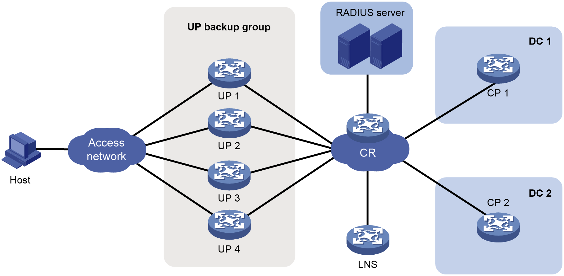
Analysis
Typically, for VPDN services and home broadband overdue users, pUP 1:3 warm standby mode, master/backup CPDR, and L2TP access are used, where pUPs acts as LACs.
For the device to operate in user plane mode, execute the work-mode user-plane command.
To implement CPDR, perform the following tasks:
· On CP 1 and CP 2, create a CPDR group with name g2 and ID 2. Specify the CPDR group as the master on CP 1 and the backup on CP 2.
· Add UPs 1026, 1027, 1028, 1029 to CPDR group g2.
To deploy configurations and service entries to UPs and exchange protocol packets with UPs, configure CP-UP channels.
To implement the UP 1:3 warm standby mode, configure the UP warm load balancing mode.
To implement switchover upon failure in UP warm standby mode, configure UP monitoring.
For users to come online, configure L2TP, AAA, and address pools.
For CPDR, you can use one loopback interface as the CP-UP tunnel interface, the CPDR tunnel interface, and the communication interface between the CP and RADIUS server. This mode features simple configuration. You can also use three different loopback interfaces. This mode features flexible configuration. In this example, one loopback interface is used as both the CP-UP tunnel interface and CPDR tunnel interface. One loopback interface is used as the communication interface between the CP and RADIUS server.
Prerequisites
Configure IP addresses for interfaces, and make sure devices can reach each other at Layer 3.
Configure the AAA server correctly. (Details not shown.)
Restrictions and guidelines
Make sure the required configurations, such as CP-UP channel, UP backup, CPDR, PPPoE, L2TP, and AAA, are performed on both CP 1 and CP 2.
The remote interface, address pool, domain, UP backup, AAA, and L2TP configurations must be the same on the two CPs.
Procedure
Configuring CPDR settings
1. Configure CP 1:
# Specify local IPv4 address 180.96.185.8 and peer IPv4 address 58.223.243.8 used for establishing CPDR channels.
<CP1> system-view
[CP1] ip vpn-instance CP2UP_L3VPN_H3C
[CP1-vpn-instance CP2UP_L3VPN_H3C] quit
[CP1] cp disaster-recovery tunnel ipv4 local 180.96.185.8 peer 58.223.243.8 vpn-instance CP2UP_L3VPN_H3C
# Create CPDR group g2 and enter CPDR group view.
[CP1] cp disaster-recovery group g2 id 2
# Assign the master role to CPDR group g2.
[CP1-cpdr-group-g2] set role master
# Add UPs 1026, 1027, 1028, 1029 to CPDR group g2.
[CP1-cpdr-group-g2] up-id 1026 1027 1028 1029
# Specify the hot backup mode for CPDR group g2. (The hot backup mode is used by default, and you can skip this configuration.)
[CP1-cpdr-group-g2] mode hot
# Enable automatic role switchover upon CPDR group failure.
[CP1-cpdr-group-g2] switchover auto enable
# Specify the source interface for sending RADIUS packets.
[CP1-cpdr-group-g2] radius source-interface LoopBack3
# Enable strict CU connection failure ratio calculation.
[CP1-cpdr-group-g2] fault-ratio-calculate strict
[CP1-cpdr-group-g2] quit
2. Configure CP 2:
# Specify local IPv4 address 58.223.243.8 and peer IPv4 address 180.96.185.8 used for establishing CPDR channels.
<CP2> system-view
[CP2] ip vpn-instance CP2UP_L3VPN_H3C
[CP2-vpn-instance CP2UP_L3VPN_H3C] quit
[CP2] cp disaster-recovery tunnel ipv4 local 58.223.243.8 peer 180.96.185.8 vpn-instance CP2UP_L3VPN_H3C
# Create CPDR group g2 and enter CPDR group view.
[CP2] cp disaster-recovery group g2 id 2
# Specify CPDR group g1 as the backup CPDR group.
[CP2-cpdr-group-g1] set role backup
# Add UPs 1026, 1027, 1028, 1029 to CPDR group g2.
[CP2-cpdr-group-g2] up-id 1026 1027 1028 1029
# Specify the hot backup mode for CPDR group g2. (The hot backup mode is used by default, and you can skip this configuration.)
[CP2-cpdr-group-g2] mode hot
# Enable automatic role switchover upon CPDR group failure.
[CP2-cpdr-group-g2] switchover auto enable
# Specify the source interface for sending RADIUS packets.
[CP2-cpdr-group-g2] radius source-interface LoopBack3
# Enable strict CU connection failure ratio calculation.
[CP2-cpdr-group-g2] fault-ratio-calculate strict
[CP2-cpdr-group-g2] quit
Configuring CP-UP channels
1. Configure UP 1:
a. Configure the device to operate in user plane mode.
# Configure the device to operate in user plane mode.
<UP1> system-view
[UP1] work-mode user-plane
b. Configure the UP as the NETCONF server.
# Enable the Stelnet server.
[UP1] ssh server enable
# Enable NETCONF over SSH.
[UP1] netconf ssh server enable
# Enable scheme authentication for user lines VTY 0 through VTY 63, through which the NETCONF over SSH clients log in.
[UP1] line vty 0 63
[UP1-line-vty0-63] authentication-mode scheme
[UP1-line-vty0-63] quit
# Add a device management user named admin and set the password to 123456TESTplat&! in plaintext form. Authorize the user to use the SSH service and assign the network-admin user role to the user.
[UP1] local-user admin class manage
[UP1-luser-manage-netconf] password simple 123456TESTplat&!
[UP1-luser-manage-netconf] service-type ssh
[UP1-luser-manage-netconf] authorization-attribute user-role network-admin
[UP1-luser-manage-netconf] quit
# Configure a BFD template. The parameter values are based on the actual network conditions. The BFD template must be configured on both the CPs and UPs.
[UP1] bfd template BFD_CUSP
[UP1-bfd-template-BFD_CUSP] bfd min-transmit-interval 200
[UP1-bfd-template-BFD_CUSP] bfd min-receive-interval 200
[UP1-bfd-template-BFD_CUSP] bfd detect-multiplier 10
[UP1-bfd-template-BFD_CUSP] quit
# Configure the server type as NETCONF and authentication mode as password authentication for SSH user admin.
[UP1] ssh user admin service-type netconf authentication-type password
2. Configure UP 2, UP 3, and UP 4:
# Configure UP 2, UP 3, and UP 4 in the same way UP 1 is configured. (Details not shown.)
3. Configure CP 1:
a. Configure the management channel for the NETCONF client:
# Create a VPN instance. This VPN instance is used for CP-UP communication to prevent attacks from the public network and hide addresses.
<CP1> system-view
[CP1] ip vpn-instance CP2UP_L3VPN_H3C
[CP1-vpn-instance CP2UP_L3VPN_H3C] quit
# Enter NETCONF client view.
[CP1] netconf-client
# Configure the source IP address for setting up a NETCONF connection to a UP.
[CP1-netconf-client] source-address 180.96.185.8
# Create NETCONF connection profile 1026 and enter NETCONF connection profile view.
[CP1-netconf-client] connection 1026
# Specify username admin and password 123456TESTplat&! for the NETCONF connection established between CP 1 and UP 1.
[CP1-netconf-client-connection-1026] user-name admin password simple 123456TESTplat&!
# Enable CP 1 to send NETCONF connection requests to the IP address of UP 1 (2.1. 1.101).
[CP1-netconf-client-connection-1026] destination-address 2.1.1.101 vpn-instance CP2UP_L3VPN_H3C
[CP1-netconf-client-connection-1026] quit
# Create NETCONF connection profile 1027 and enter NETCONF connection profile view.
[CP1-netconf-client] connection 1027
# Specify username admin and password 123456TESTplat&! for the NETCONF connection established between CP 1 and UP 2.
[CP1-netconf-client-connection-1027] user-name admin password simple 123456TESTplat&!
# Enable CP 1 to send NETCONF connection requests to the IP address of UP 2 (2.1.1.102).
[CP1-netconf-client-connection-1027] destination-address 2.1.1.102 vpn-instance CP2UP_L3VPN_H3C
[CP1-netconf-client-connection-1027] quit
# Configure NETCONF connection 1028 and enter NETCONF connection profile view.
[CP1-netconf-client] connection 1028
# Specify username admin and password 123456TESTplat&! for the NETCONF connection established between CP 1 and UP 3.
[CP1-netconf-client-connection-1028] user-name admin password simple 123456TESTplat&!
# Enable CP 1 to send NETCONF connection requests to the IP address of UP 3 (2.1.1.103).
[CP1-netconf-client-connection-1028] destination-address 2.1.1.103 vpn-instance CP2UP_L3VPN_H3C
[CP1-netconf-client-connection-1028] quit
# Create NETCONF connection profile 1029 and enter NETCONF connection profile view.
[CP1-netconf-client] connection 1029
# Specify username admin and password 123456TESTplat&! for the NETCONF connection established between CP 1 and UP 4.
[CP1-netconf-client-connection-1029] user-name admin password simple 123456TESTplat&!
# Enable CP 1 to send NETCONF connection requests to the IP address of UP 4 (2.1.1.104).
[CP1-netconf-client-connection-1029] destination-address 2.1.1.104 vpn-instance CP2UP_L3VPN_H3C
[CP1-netconf-client-connection-1029] quit
[CP1-netconf-client] quit
# Create UP 1026 and enter UP-manage view.
[CP1] up-manage id 1026
# Bind UP 1026 to NETCONF connection profile 1026.
[CP1-up-manage-1026] bind netconf-connection 1026
[CP1-up-manage-1026] quit
# Create UP 1027 and enter UP-manage view.
[CP1] up-manage id 1027
# Bind UP 1027 to NETCONF connection profile 1027.
[CP1-up-manage-1027] bind netconf-connection 1027
[CP1-up-manage-1027] quit
# Create UP 1028 and enter UP-manage view.
[CP1] up-manage id 1028
# Bind UP 1028 to NETCONF connection profile 1028.
[CP1-up-manage-1028] bind netconf-connection 1028
[CP1-up-manage-1028] quit
# Create UP 1029 and enter UP-manage view.
[CP1] up-manage id 1029
# Bind UP 1029 to NETCONF connection profile 1029.
[CP1-up-manage-1029] bind netconf-connection 1029
[CP1-up-manage-1029] quit
b. Configure protocol channels for the CP:
# Configure a protocol channel between CP 1 and UP 1, with VXLAN ID 11026, source IP address 180.96.185.8, and destination IP address 2.1.1.101.
[CP1] up-manage id 1026
[CP1-up-manage-1026] protocol-tunnel vxlan 11026 source 180.96.185.8 destination 2.1.1.101 vpn-instance CP2UP_L3VPN_H3C
[CP1-up-manage-1026] quit
# Configure a protocol channel between CP 1 and UP 2, with VXLAN ID 11027, source IP address 180.96.185.8, and destination IP address 2.1.1.102.
[CP1] up-manage id 1027
[CP1-up-manage-1027] protocol-tunnel vxlan 11027 source 180.96.185.8 destination 2.1.1.102 vpn-instance CP2UP_L3VPN_H3C
[CP1-up-manage-1027] quit
# Configure a protocol channel between CP 1 and UP 3, with VXLAN ID 11028, source IP address 180.96.185.8, and destination IP address 2.1.1.103.
[CP1] up-manage id 1028
[CP1-up-manage-1028] protocol-tunnel vxlan 11028 source 180.96.185.8 destination 2.1.1.103 vpn-instance CP2UP_L3VPN_H3C
[CP1-up-manage-1028] quit
# Configure a protocol channel between CP 1 and UP 4, with VXLAN ID 11029, source IP address 180.96.185.8, and destination IP address 2.1.1.104.
[CP1] up-manage id 1029
[CP1-up-manage-1029] protocol-tunnel vxlan 11029 source 180.96.185.8 destination 2.1.1.104 vpn-instance CP2UP_L3VPN_H3C
[CP1-up-manage-1029] quit
c. Configure protocol channels for UPs:
# Create UP 1026 and enter UP-config view.
[CP1] up-manage id 1026
[CP1-up-manage-1026] up-config
# In CU-agent view, configure a protocol channel between UP 1 and CP 1, with VXLAN ID 11026, source IP address 2.1.1.101, and destination IP address 180.96.185.8. Configure a protocol channel between UP 1 and CP 2, with VXLAN ID 21026, source IP address 2.1.1.101, and destination IP address 58.223.243.8.
[CP1-up-manage-1026-up-config] cu-agent
[CP1-up-manage-1026-up-config-cu-agent] protocol-tunnel vxlan 11026 source 2.1.1.101 destination 180.96.185.8 vpn-instance CP2UP_L3VPN_H3C
[CP1-up-manage-1026-up-config-cu-agent] protocol-tunnel vxlan 21026 source 2.1.1.101 destination 58.223.243.8 vpn-instance CP2UP_L3VPN_H3C
[CP1-up-manage-1026-up-config-cu-agent] quit
[CP1-up-manage-1026-up-config] quit
[CP1-up-manage-1026] quit
# Create UP 1027 and enter UP-config view.
[CP1] up-manage id 1027
[CP1-up-manage-1027] up-config
# In CU-agent view, configure a protocol channel between UP 2 and CP 1, with VXLAN ID 11027, source IP address 2.1.1.102, and destination IP address 180.96.185.8. Configure a protocol channel between UP 2 and CP 2, with VXLAN ID 21027, source IP address 2.1.1.102, and destination IP address 58.223.243.8.
[CP1-up-manage-1027-up-config] cu-agent
[CP1-up-manage-1027-up-config-cu-agent] protocol-tunnel vxlan 11027 source 2.1.1.102 destination 180.96.185.8 vpn-instance CP2UP_L3VPN_H3C
[CP1-up-manage-1027-up-config-cu-agent] protocol-tunnel vxlan 21027 source 2.1.1.102 destination 58.223.243.8 vpn-instance CP2UP_L3VPN_H3C
[CP1-up-manage-1027-up-config-cu-agent] quit
[CP1-up-manage-1027-up-config] quit
[CP1-up-manage-1027] quit
# Create UP 1028 and enter UP-config view.
[CP1] up-manage id 1028
[CP1-up-manage-1028] up-config
# In CU-agent view, configure a protocol channel between UP 3 and CP 1, with VXLAN ID 11028, source IP address 2.1.1.103, and destination IP address 180.96.185.8. Configure a protocol channel between UP 3 and CP 2, with VXLAN ID 21028, source IP address 2.1.1.103, and destination IP address 58.223.243.8.
[CP1-up-manage-1028-up-config] cu-agent
[CP1-up-manage-1028-up-config-cu-agent] protocol-tunnel vxlan 11028 source 2.1.1.103 destination 180.96.185.8 vpn-instance CP2UP_L3VPN_H3C
[CP1-up-manage-1028-up-config-cu-agent] protocol-tunnel vxlan 21028 source 2.1.1.103 destination 58.223.243.8 vpn-instance CP2UP_L3VPN_H3C
[CP1-up-manage-1028-up-config-cu-agent] quit
[CP1-up-manage-1028-up-config] quit
[CP1-up-manage-1028] quit
# Create UP 1029 and enter UP-config view.
[CP1] up-manage id 1029
[CP1-up-manage-1029] up-config
# In CU-agent view, configure a protocol channel between UP 4 and CP 1, with VXLAN ID 11029, source IP address 2.1.1.104, and destination IP address 180.96.185.8. Configure a protocol channel between UP 4 and CP 2, with VXLAN ID 21029, source IP address 2.1.1.104, and destination IP address 58.223.243.8.
[CP1-up-manage-1029-up-config] cu-agent
[CP1-up-manage-1029-up-config-cu-agent] protocol-tunnel vxlan 11029 source 2.1.1.104 destination 180.96.185.8 vpn-instance CP2UP_L3VPN_H3C
[CP1-up-manage-1029-up-config-cu-agent] protocol-tunnel vxlan 21029 source 2.1.1.104 destination 58.223.243.8 vpn-instance CP2UP_L3VPN_H3C
[CP1-up-manage-1029-up-config-cu-agent] quit
[CP1-up-manage-1029-up-config] quit
[CP1-up-manage-1029] quit
d. Configure control channels for the CP:
# Enable the CUSP controller feature and enter CUSP controller view.
[CP1] cusp controller
# Specify the listening IP address as 180.96.185.8 for the CUSP controller.
[CP1-cusp-controller] listening-ip 180.96.185.8
# Enable BFD for CUSP.
[CP1-cusp-controller] bfd enable template BFD_CUSP
# Create CUSP agent up1 and enter CUSP agent view.
[CP1-cusp-controller] agent up1
# Configure the IP address for CUSP agent up1 as 2.1.1.101.
[CP1-cusp-controller-agent-up1] agent-ip 2.1.1.101
[CP1-cusp-controller-agent-up1] quit
# Create CUSP agent up2 and enter CUSP agent view.
[CP1-cusp-controller] agent up2
# Configure the IP address for CUSP agent up2 as 2.1.1.102.
[CP1-cusp-controller-agent-up2] agent-ip 2.1.1.102
[CP1-cusp-controller-agent-up2] quit
# Create CUSP agent up3 and enter CUSP agent view.
[CP1-cusp-controller] agent up3
# Configure the IP address for CUSP agent up3 as 2.1.1.103.
[CP1-cusp-controller-agent-up3] agent-ip 2.1.1.103
[CP1-cusp-controller-agent-up3] quit
# Create CUSP agent up4 and enter CUSP agent view.
[CP1-cusp-controller] agent up4
# Configure the IP address for CUSP agent up4 as 2.1.1.104.
[CP1-cusp-controller-agent-up4] agent-ip 2.1.1.104
[CP1-cusp-controller-agent-up4] quit
[CP1-cusp-controller] quit
# Enable control channel establishment for UP 1026 by using CUSP agent up1.
[CP1] up-manage id 1026
[CP1-up-manage-1026] control-tunnel cusp-agent up1
[CP1-up-manage-1026] quit
# Enable control channel establishment for UP 1027 by using CUSP agent up2.
[CP1] up-manage id 1027
[CP1-up-manage-1027] control-tunnel cusp-agent up2
[CP1-up-manage-1027] quit
# Enable control channel establishment for UP 1028 by using CUSP agent up3.
[CP1] up-manage id 1028
[CP1-up-manage-1028] control-tunnel cusp-agent up3
[CP1-up-manage-1028] quit
# Enable control channel establishment for UP 1029 by using CUSP agent up4.
[CP1] up-manage id 1029
[CP1-up-manage-1029] control-tunnel cusp-agent up4
[CP1-up-manage-1029] quit
e. Configure control channels for UPs:
# Configure a BFD template. The parameter values are based on the actual network conditions. The BFD template must be configured on both the CPs and UPs.
[CP1] bfd template BFD_CUSP
[CP1-bfd-template-BFD_CUSP] bfd min-transmit-interval 200
[CP1-bfd-template-BFD_CUSP] bfd min-receive-interval 200
[CP1-bfd-template-BFD_CUSP] bfd detect-multiplier 10
[CP1-bfd-template-BFD_CUSP] quit
# Enter UP-config view.
[CP1] up-manage id 1026
[CP1-up-manage-1026] up-config
# Create CUSP agent up1 and enter CUSP agent view.
[CP1-up-manage-1026-up-config] cusp agent up1
# Enable UP 1 to establish CUSP connections with CP 1 (180.96.185.8) and CP 2 (58.223.243.8) by using source IP address 2.1.1.101, and enable BFD for CUSP.
[CP1-up-manage-1026-up-config-cusp-agent-up1] local-address 2.1.1.101 vpn-instance CP2UP_L3VPN_H3C
[CP1-up-manage-1026-up-config-cusp-agent-up1] controller address 180.96.185.8
[CP1-up-manage-1026-up-config-cusp-agent-up1] controller address 58.223.243.8
[CP1-up-manage-1026-up-config-cusp-agent-up1] bfd enable template BFD_CUSP
[CP1-up-manage-1026-up-config-cusp-agent-up1] quit
[CP1-up-manage-1026-up-config] quit
[CP1-up-manage-1026] quit
# Enter UP-config view.
[CP1] up-manage id 1027
[CP1-up-manage-1027] up-config
# Create CUSP agent up2 and enter CUSP agent view.
[CP1-up-manage-1027-up-config] cusp agent up2
# Enable UP 2 to establish CUSP connections with CP 1 (180.96.185.8) and CP 2 (58.223.243.8) by using source IP address 2.1.1.102, and enable BFD for CUSP.
[CP1-up-manage-1027-up-config-cusp-agent-up2] local-address 2.1.1.102 vpn-instance CP2UP_L3VPN_H3C
[CP1-up-manage-1027-up-config-cusp-agent-up2] controller address 180.96.185.8
[CP1-up-manage-1027-up-config-cusp-agent-up2] controller address 58.223.243.8
[CP1-up-manage-1027-up-config-cusp-agent-up2] bfd enable template BFD_CUSP
[CP1-up-manage-1027-up-config-cusp-agent-up2] quit
[CP1-up-manage-1027-up-config] quit
[CP1-up-manage-1027] quit
# Enter UP-config view.
[CP1] up-manage id 1028
[CP1-up-manage-1028] up-config
# Create CUSP agent up3 and enter CUSP agent view.
[CP1-up-manage-1028-up-config] cusp agent up3
# Enable UP 3 to establish CUSP connections with CP 1 (180.96.185.8) and CP 2 (58.223.243.8) by using source IP address 2.1.1.103, and enable BFD for CUSP.
[CP1-up-manage-1028-up-config-cusp-agent-up3] local-address 2.1.1.103 vpn-instance CP2UP_L3VPN_H3C
[CP1-up-manage-1028-up-config-cusp-agent-up3] controller address 180.96.185.8
[CP1-up-manage-1028-up-config-cusp-agent-up3] controller address 58.223.243.8
[CP1-up-manage-1028-up-config-cusp-agent-up3] bfd enable template BFD_CUSP
[CP1-up-manage-1028-up-config-cusp-agent-up3] quit
[CP1-up-manage-1028-up-config] quit
[CP1-up-manage-1028] quit
# Enter UP-config view.
[CP1] up-manage id 1029
[CP1-up-manage-1029] up-config
# Create CUSP agent up4 and enter CUSP agent view.
[CP1-up-manage-1029-up-config] cusp agent up4
# Enable UP 4 to establish CUSP connections with CP 1 (180.96.185.8) and CP 2 (58.223.243.8) by using source IP address 2.1.1.104, and enable BFD for CUSP.
[CP1-up-manage-1029-up-config-cusp-agent-up4] local-address 2.1.1.104 vpn-instance CP2UP_L3VPN_H3C
[CP1-up-manage-1029-up-config-cusp-agent-up4] controller address 180.96.185.8
[CP1-up-manage-1029-up-config-cusp-agent-up4] controller address 58.223.243.8
[CP1-up-manage-1029-up-config-cusp-agent-up4] bfd enable template BFD_CUSP
[CP1-up-manage-1029-up-config-cusp-agent-up4] quit
[CP1-up-manage-1029-up-config] quit
[CP1-up-manage-1029] quit
f. Create remote interfaces:
# Create remote UP interface Route-Aggregation701 for UP 1026.
[CP1] up-manage id 1026
[CP1-up-manage-1026] remote interface Route-Aggregation701
[CP1-up-manage-1026] quit
# Create remote UP interface Route-Aggregation701 for UP 1027.
[CP1] up-manage id 1027
[CP1-up-manage-1027] remote interface Route-Aggregation701
[CP1-up-manage-1027] quit
# Create remote UP interface Route-Aggregation701 for UP 1028.
[CP1] up-manage id 1028
[CP1-up-manage-1028] remote interface Route-Aggregation701
[CP1-up-manage-1028] quit
# Create remote UP interface Route-Aggregation701 for UP 1029.
[CP1] up-manage id 1029
[CP1-up-manage-1029] remote interface Route-Aggregation701
[CP1-up-manage-1029] quit
4. Configure CP 2:
a. Configure the management channel for the NETCONF client:
# Create a VPN instance. This VPN instance is used for CP-UP communication to prevent attacks from the public network and hide addresses.
<CP2> system-view
[CP2] ip vpn-instance CP2UP_L3VPN_H3C
[CP2-vpn-instance CP2UP_L3VPN_H3C] quit
# Enter NETCONF client view.
[CP2] netconf-client
# Configure the source IP address for setting up a NETCONF connection to a UP.
[CP2-netconf-client] source-address 58.223.243.8
# Create NETCONF connection profile 1026 and enter NETCONF connection profile view.
[CP2-netconf-client] connection 1026
# Specify username admin and password 123456TESTplat&! for the NETCONF connection established between CP 2 and UP 1.
[CP2-netconf-client-connection-1026] user-name admin password simple 123456TESTplat&!
# Enable CP 2 to send NETCONF connection requests to the IP address of UP 1 (2.1.1.101).
[CP2-netconf-client-connection-1026] destination-address 2.1.1.101 vpn-instance CP2UP_L3VPN_H3C
[CP2-netconf-client-connection-1026] quit
# Create NETCONF connection profile 1027 and enter NETCONF connection profile view.
[CP2-netconf-client] connection 1027
# Specify username admin and password 123456TESTplat&! for the NETCONF connection established between CP 2 and UP 2.
[CP2-netconf-client-connection-1027] user-name admin password simple 123456TESTplat&!
# Enable CP 2 to send NETCONF connection requests to the IP address of UP 2 (2.1.1.102).
[CP2-netconf-client-connection-1027] destination-address 2.1.1.102 vpn-instance CP2UP_L3VPN_H3C
[CP2-netconf-client-connection-1027] quit
# Configure NETCONF connection 1028 and enter NETCONF connection profile view.
[CP2-netconf-client] connection 1028
# Specify username admin and password 123456TESTplat&! for the NETCONF connection established between CP 2 and UP 3.
[CP2-netconf-client-connection-1028] user-name admin password simple 123456TESTplat&!
# Enable CP 2 to send NETCONF connection requests to the IP address of UP 2 (2.1.1.103).
[CP2-netconf-client-connection-1028] destination-address 2.1.1.103 vpn-instance CP2UP_L3VPN_H3C
[CP2-netconf-client-connection-1028] quit
# Create NETCONF connection profile 1029 and enter NETCONF connection profile view.
[CP2-netconf-client] connection 1029
# Specify username admin and password 123456TESTplat&! for the NETCONF connection established between CP 2 and UP 4.
[CP2-netconf-client-connection-1029] user-name admin password simple 123456TESTplat&!
# Enable CP 2 to send NETCONF connection requests to the IP address of UP 4 (2.1.1.104).
[CP2-netconf-client-connection-1029] destination-address 2.1.1.104 vpn-instance CP2UP_L3VPN_H3C
[CP2-netconf-client-connection-1029] quit
[CP2-netconf-client] quit
# Create UP 1026 and enter UP-manage view.
[CP2] up-manage id 1026
# Bind UP 1026 to NETCONF connection profile 1026.
[CP2-up-manage-1026] bind netconf-connection 1026
[CP2-up-manage-1026] quit
# Create UP 1027 and enter UP-manage view.
[CP2] up-manage id 1027
# Bind UP 1027 to NETCONF connection profile 1027.
[CP2-up-manage-1027] bind netconf-connection 1027
[CP2-up-manage-1027] quit
# Create UP 1028 and enter UP-manage view.
[CP2] up-manage id 1028
# Bind UP 1028 to NETCONF connection profile 1028.
[CP2-up-manage-1028] bind netconf-connection 1028
[CP2-up-manage-1028] quit
# Create UP 1029 and enter UP-manage view.
[CP2] up-manage id 1029
# Bind UP 1029 to NETCONF connection profile 1029.
[CP2-up-manage-1029] bind netconf-connection 1029
[CP2-up-manage-1029] quit
b. Configure protocol channels for the CP:
# Configure a protocol channel between CP 2 and UP 1, with VXLAN ID 21026, source IP address 58,223,243.8, and destination IP address 2.1. 1.101.
[CP2] up-manage id 1026
[CP2-up-manage-1026] protocol-tunnel vxlan 21026 source 58.223.243.8 destination 2.1.1.101 vpn-instance CP2UP_L3VPN_H3C
[CP2-up-manage-1026] quit
# Configure a protocol channel between CP 2 and UP 2, with VXLAN ID 21027, source IP address 58,223,243.8, and destination IP address 2.1.1.102.
[CP2] up-manage id 1027
[CP2-up-manage-1027] protocol-tunnel vxlan 21027 source 58.223.243.8 destination 2.1.1.102 vpn-instance CP2UP_L3VPN_H3C
[CP2-up-manage-1027] quit
# Configure a protocol channel between CP 2 and UP 3, with VXLAN ID 21028, source IP address 58,223,243.8, and destination IP address 2.1.1.103.
[CP2] up-manage id 1028
[CP2-up-manage-1028] protocol-tunnel vxlan 21028 source 58.223.243.8 destination 2.1.1.102 vpn-instance CP2UP_L3VPN_H3C
[CP2-up-manage-1028] quit
# Configure a protocol channel between CP 2 and UP 4, with VXLAN ID 21029, source IP address 58,223,243.8, and destination IP address 2.1.1.104.
[CP2] up-manage id 1029
[CP2-up-manage-1029] protocol-tunnel vxlan 21029 source 58.223.243.8 destination 2.1.1.104 vpn-instance CP2UP_L3VPN_H3C
[CP2-up-manage-1029] quit
c. Configure protocol channels for UPs:
# Create UP 1026 and enter UP-config view.
[CP2] up-manage id 1026
[CP2-up-manage-1026] up-config
# In CU-agent view, configure a protocol channel between UP 1 and CP 1, with VXLAN ID 11026, source IP address 2.1.1.101, and destination IP address 180.96.185.8. Configure a protocol channel between UP 1 and CP 2, with VXLAN ID 21026, source IP address 2.1.1.101, and destination IP address 58.223.243.8.
[CP2-up-manage-1026-up-config] cu-agent
[CP2-up-manage-1026-up-config-cu-agent] protocol-tunnel vxlan 11026 source 2.1.1.101 destination 180.96.185.8 vpn-instance CP2UP_L3VPN_H3C
[CP2-up-manage-1026-up-config-cu-agent] protocol-tunnel vxlan 21026 source 2.1.1.101 destination 58.223.243.8 vpn-instance CP2UP_L3VPN_H3C
[CP2-up-manage-1026-up-config-cu-agent] quit
[CP2-up-manage-1026-up-config] quit
[CP2-up-manage-1026] quit
# Create UP 1027 and enter UP-config view.
[CP2] up-manage id 1027
[CP2-up-manage-1027] up-config
# In CU-agent view, configure a protocol channel between UP 2 and CP 1, with VXLAN ID 11027, source IP address 2.1.1.102, and destination IP address 180.96.185.8. Configure a protocol channel between UP 2 and CP 2, with VXLAN ID 21027, source IP address 2.1.1.102, and destination IP address 58.223.243.8.
[CP2-up-manage-1027-up-config] cu-agent
[CP2-up-manage-1027-up-config-cu-agent] protocol-tunnel vxlan 11027 source 2.1.1.102 destination 180.96.185.8 vpn-instance CP2UP_L3VPN_H3C
[CP2-up-manage-1027-up-config-cu-agent] protocol-tunnel vxlan 21027 source 2.1.1.102 destination 58.223.243.8 vpn-instance CP2UP_L3VPN_H3C
[CP2-up-manage-1027-up-config-cu-agent] quit
[CP2-up-manage-1027-up-config] quit
[CP2-up-manage-1027] quit
# Create UP 1028 and enter UP-config view.
[CP2] up-manage id 1028
[CP2-up-manage-1028] up-config
# In CU-agent view, configure a protocol channel between UP 3 and CP 1, with VXLAN ID 11028, source IP address 2.1.1.103, and destination IP address 180.96.185.8. Configure a protocol channel between UP 3 and CP 2, with VXLAN ID 21028, source IP address 2.1.1.103, and destination IP address 58.223.243.8.
[CP2-up-manage-1028-up-config] cu-agent
[CP2-up-manage-1028-up-config-cu-agent] protocol-tunnel vxlan 11028 source 2.1.1.103 destination 180.96.185.8 vpn-instance CP2UP_L3VPN_H3C
[CP2-up-manage-1028-up-config-cu-agent] protocol-tunnel vxlan 21028 source 2.1.1.103 destination 58.223.243.8 vpn-instance CP2UP_L3VPN_H3C
[CP2-up-manage-1028-up-config-cu-agent] quit
[CP2-up-manage-1028-up-config] quit
[CP2-up-manage-1028] quit
# Create UP 1029 and enter UP-config view.
[CP2] up-manage id 1029
[CP2-up-manage-1029] up-config
# In CU-agent view, configure a protocol channel between UP 4 and CP 1, with VXLAN ID 11029, source IP address 2.1.1.104, and destination IP address 180.96.185.8. Configure a protocol channel between UP 4 and CP 2, with VXLAN ID 21029, source IP address 2.1.1.104, and destination IP address 58.223.243.8.
[CP2-up-manage-1029-up-config] cu-agent
[CP2-up-manage-1029-up-config-cu-agent] protocol-tunnel vxlan 11029 source 2.1.1.104 destination 180.96.185.8 vpn-instance CP2UP_L3VPN_H3C
[CP2-up-manage-1029-up-config-cu-agent] protocol-tunnel vxlan 21029 source 2.1.1.104 destination 58.223.243.8 vpn-instance CP2UP_L3VPN_H3C
[CP2-up-manage-1029-up-config-cu-agent] quit
[CP2-up-manage-1029-up-config] quit
[CP2-up-manage-1029] quit
d. Configure the control channel for the CP:
# Enable the CUSP controller feature and enter CUSP controller view.
[CP2] cusp controller
# Specify the listening IP address as 58.223.243.8 for the CUSP controller, and enable BFD for CUSP.
[CP2-cusp-controller] listening-ip 58.223.243.8 vpn-instance CP2UP_L3VPN_H3C
[CP2-cusp-controller] bfd enable template BFD_CUSP
# Create CUSP agent up1 and enter CUSP agent view.
[CP2-cusp-controller] agent up1
# Configure the IP address for CUSP agent up1 as 2.1. 1.101.
[CP2-cusp-controller-agent-up1] agent-ip 2.1.1.101
[CP2-cusp-controller-agent-up1] quit
# Create CUSP agent up2 and enter CUSP agent view.
[CP2-cusp-controller] agent up2
# Configure the IP address for CUSP agent up2 as 2.1.1.102.
[CP2-cusp-controller-agent-up2] agent-ip 2.1.1.102
[CP2-cusp-controller-agent-up2] quit
# Create CUSP agent up3 and enter CUSP agent view.
[CP2-cusp-controller] agent up3
# Configure the IP address for CUSP agent up3 as 2.1.1.103.
[CP2-cusp-controller-agent-up3] agent-ip 2.1.1.103
[CP2-cusp-controller-agent-up3] quit
# Create CUSP agent up4 and enter CUSP agent view.
[CP2-cusp-controller] agent up4
# Configure the IP address for CUSP agent up4 as 2.1.1.104.
[CP2-cusp-controller-agent-up4] agent-ip 2.1.1.104
[CP2-cusp-controller-agent-up4] quit
[CP2-cusp-controller] quit
# Enable control channel establishment for UP 1026 by using CUSP agent up1.
[CP2] up-manage id 1026
[CP2-up-manage-1026] control-tunnel cusp-agent up1
[CP2-up-manage-1026] quit
# Enable control channel establishment for UP 1027 by using CUSP agent up2.
[CP2] up-manage id 1027
[CP2-up-manage-1027] control-tunnel cusp-agent up2
[CP2-up-manage-1027] quit
# Enable control channel establishment for UP 1028 by using CUSP agent up3.
[CP2] up-manage id 1028
[CP2-up-manage-1028] control-tunnel cusp-agent up3
[CP2-up-manage-1028] quit
# Enable control channel establishment for UP 1029 by using CUSP agent up4.
[CP2] up-manage id 1029
[CP2-up-manage-1029] control-tunnel cusp-agent up4
[CP2-up-manage-1029] quit
e. Configure the control channel for UPs:
# Configure a BFD template. The parameter values are based on the actual network conditions. The BFD template must be configured on both the CP and UPs.
[CP2] bfd template BFD_CUSP
[CP2-bfd-template-BFD_CUSP] bfd min-transmit-interval 200
[CP2-bfd-template-BFD_CUSP] bfd min-receive-interval 200
[CP2-bfd-template-BFD_CUSP] bfd detect-multiplier 10
[CP2-bfd-template-BFD_CUSP] quit
# Enter UP-config view.
[CP2] up-manage id 1026
[CP2-up-manage-1026] up-config
# Create CUSP agent up1 and enter CUSP agent view.
[CP2-up-manage-1026-up-config] cusp agent up1
# Enable UP 1 to establish CUSP connections with CP 1 (180.96.185.8) and CP 2 (58.223.243.8) by using source IP address 2.1.1.101, and enable BFD for CUSP.
[CP2-up-manage-1026-up-config-cusp-agent-up1] local-address 2.1.1.101 vpn-instance CP2UP_L3VPN_H3C
[CP2-up-manage-1026-up-config-cusp-agent-up1] controller address 180.96.185.8
[CP2-up-manage-1026-up-config-cusp-agent-up1] controller address 58.223.243.8
[CP2-up-manage-1026-up-config-cusp-agent-up1] bfd enable template BFD_CUSP
[CP2-up-manage-1026-up-config-cusp-agent-up1] quit
[CP2-up-manage-1026-up-config] quit
[CP2-up-manage-1026] quit
# Enter UP-config view.
[CP2] up-manage id 1027
[CP2-up-manage-1027] up-config
# Create CUSP agent up2 and enter CUSP agent view.
[CP2-up-manage-1027-up-config] cusp agent up2
# Enable UP 2 to establish CUSP connections with CP 1 (180.96.185.8) and CP 2 (58.223.243.8) by using source IP address 2.1.1.102, and enable BFD for CUSP.
[CP2-up-manage-1027-up-config-cusp-agent-up1] local-address 2.1.1.102 vpn-instance CP2UP_L3VPN_H3C
[CP2-up-manage-1027-up-config-cusp-agent-up1] controller address 180.96.185.8
[CP2-up-manage-1027-up-config-cusp-agent-up1] controller address 58.223.243.8
[CP2-up-manage-1027-up-config-cusp-agent-up1] bfd enable template BFD_CUSP
[CP2-up-manage-1027-up-config-cusp-agent-up1] quit
[CP2-up-manage-1027-up-config] quit
[CP2-up-manage-1027] quit
# Enter UP-config view.
[CP2] up-manage id 1028
[CP2-up-manage-1028] up-config
# Create CUSP agent up3 and enter CUSP agent view.
[CP2-up-manage-1028-up-config] cusp agent up3
# Enable UP 3 to establish CUSP connections with CP 1 (180.96.185.8) and CP 2 (58.223.243.8) by using source IP address 2.1.1.103, and enable BFD for CUSP.
[CP2-up-manage-1028-up-config-cusp-agent-up1] local-address 2.1.1.103 vpn-instance CP2UP_L3VPN_H3C
[CP2-up-manage-1028-up-config-cusp-agent-up1] controller address 180.96.185.8
[CP2-up-manage-1028-up-config-cusp-agent-up1] controller address 58.223.243.8
[CP2-up-manage-1028-up-config-cusp-agent-up1] bfd enable template BFD_CUSP
[CP2-up-manage-1028-up-config-cusp-agent-up1] quit
[CP2-up-manage-1028-up-config] quit
[CP2-up-manage-1028] quit
# Enter UP-config view.
[CP2] up-manage id 1029
[CP2-up-manage-1029] up-config
# Create CUSP agent up4 and enter CUSP agent view.
[CP2-up-manage-1029-up-config] cusp agent up4
# Enable UP 4 to establish CUSP connections with CP 1 (180.96.185.8) and CP 2 (58.223.243.8) by using source IP address 2.1.1.104, and enable BFD for CUSP.
[CP2-up-manage-1029-up-config-cusp-agent-up4] local-address 2.1.1.104 vpn-instance CP2UP_L3VPN_H3C
[CP2-up-manage-1029-up-config-cusp-agent-up4] controller address 180.96.185.8
[CP2-up-manage-1029-up-config-cusp-agent-up4] controller address 58.223.243.8
[CP2-up-manage-1029-up-config-cusp-agent-up4] bfd enable template BFD_CUSP
[CP2-up-manage-1029-up-config-cusp-agent-up4] quit
[CP2-up-manage-1029-up-config] quit
[CP2-up-manage-1029] quit
f. Create remote interfaces:
# Create remote UP interface Route-Aggregation701 for UP 1026.
[CP2] up-manage id 1026
[CP2-up-manage-1026] remote interface Route-Aggregation701
[CP2-up-manage-1026] quit
# Create remote UP interface Route-Aggregation701 for UP 1027.
[CP2] up-manage id 1027
[CP2-up-manage-1027] remote interface Route-Aggregation701
[CP2-up-manage-1027] quit
# Create remote UP interface Route-Aggregation701 for UP 1028.
[CP2] up-manage id 1028
[CP2-up-manage-1028] remote interface Route-Aggregation701
[CP2-up-manage-1028] quit
# Create remote UP interface Route-Aggregation701 for UP 1029.
[CP2] up-manage id 1029
[CP2-up-manage-1029] remote interface Route-Aggregation701
[CP2-up-manage-1029] quit
Configuring UP backup
1. Configure CP 1:
a. Configure a UP backup group.
[CP1] up-backup-group group2
[CP1-up-backup-group-group2] backup up-id 1026
[CP1-up-backup-group-group2] backup up-id 1027
[CP1-up-backup-group-group2] backup up-id 1028
[CP1-up-backup-group-group2] backup up-id 1029
[CP1-up-backup-group-group2] quit
b. Configure a UP backup profile:
# Create UP backup profile 2 in warm standby mode.
[CP1] up-backup-profile 2 warm-load-balance
# Specify master interfaces for the UP backup profile.
[CP1-up-backup-profile-2] master-interface Remote-RAGG1026/701 vrid 1
[CP1-up-backup-profile-2] master-interface Remote-RAGG1027/701 vrid 2
[CP1-up-backup-profile-2] master-interface Remote-RAGG1028/701 vrid 3
[CP1-up-backup-profile-2] master-interface Remote-RAGG1029/701 vrid 4
# Specify the interface-based method to select master interfaces and load balances traffic based on the outer VLAN and inner VLAN.
[CP1-up-backup-profile-2] load-balance-mode interface by-qinq
# Disable the original master UP or interface from switching back to master upon failure recovery.
[CP1-up-backup-profile-2] undo failure-recovery-switch enable
# Configure the logical access interface for UP backup profile 1 as Remote-RAGG1026/701. When the CP sends RADIUS packets to the RADIUS server, it adds the logical access interface specified in this command to the NAS-Port-ID attribute in the RADIUS packets.
[CP1-up-backup-profile-2] nas logic-port Remote-RAGG1026/701
# Configure the switchover delay upon CUSP channel failure as 5 seconds.
[CP1-up-backup-profile-2] control-tunnel-down switchover delay 5
# Configure the switchover delay upon CUSP channel failure recovery as 60000 milliseconds.
[CP1-up-backup-profile-2] control-tunnel-up switchover msec-delay 60000
2. Configure CP 2:
Configure CP 2 in the same way CP 1 is configured. (Details not shown.)
Configuring UP monitoring
1. Configure UP 1:
# Create a static BFD session and enter its view. The static BFD session detects the next-hop address for the network-side interface and two output interfaces for the next hop.
[UP1] bfd static up1toSLEAF1 peer-ipv6 2:1:1::5 source-ipv6 2:1:1::101 discriminator auto
[UP1-bfd-static-session-up1oSLEAF1] bfd multi-hop detect-multiplier 10
[UP1-bfd-static-session-up1oSLEAF1] quit
[UP1] bfd static up1toSLEAF2 peer-ipv6 2:1:1::6 source-ipv6 2:1:1::101 discriminator auto
[UP1-bfd-static-session-up1oSLEAF2] bfd multi-hop detect-multiplier 10
[UP1-bfd-static-session-up1oSLEAF2] quit
[UP1] track 1 bfd static up1oSLEAF1
[UP1] track 2 bfd static up1oSLEAF2
[UP1-track-1] quit
# Create Boolean OR list 5 and enter its view. Add track entries 1 and 2 as tracked objects to the list.
[UP1] track 5 list boolean or
[UP1-track-5] object 1
[UP1-track-5] object 2
[UP1-track-5] quit
# Disable master/backup interface switchover on the UP, and specify track entry 5 to monitor the link between the UP and the upstream router.
[UP1] user-plane control-tunnel-down switchover track 5
# Configure network-side bandwidth detection.
[UP1] track 12 bfd echo interface HundredGigE2/2/1 remote ipv6 176:1:1:13::7 local ipv6 176:1:1:13::6
[UP1] track 13 bfd echo interface HundredGigE2/1/1 remote ipv6 176:1:1:2::3 local ipv6 176:1:1:2::2
[UP1] track 14 bfd echo interface HundredGigE4/2/1 remote ipv6 176:1:1:1::3 local ipv6 176:1:1:1::2
[UP1] track 15 bfd echo interface HundredGigE4/1/1 remote ipv6 176:1:1:13::3 local ipv6 176:1:1:13::2
# Create a percentage threshold list and enter its view. Set the negative state threshold to 49% and the positive state threshold to 50% for the percentage threshold list.
[UP1] track 16 list threshold percentage
[UP1-track-16] threshold percentage negative 49 positive 50
[UP1-track-16] object 12
[UP1-track-16] object 13
[UP1-track-16] object 14
[UP1-track-16] object 15
[UP1-track-16] quit
# Create Boolean AND list 11 and enter its view. Add track entry 16 as a tracked object to the list.
[UP1] track 11 list boolean and
[UP1-track-11] object 16
[UP1-track-11] quit
# Associate the UP with track entry 11.
[UP1] user-plane switchover track 11 uplink-group JH-CN-PUP1026
2. Configure UP 2:
# Create a static BFD session and enter its view. The static BFD session detects the next-hop address for the network-side interface.
[UP2] bfd static up2toSLEAF1 peer-ipv6 2:1:1::5 source-ipv6 2:1:1::102 discriminator auto
[UP2-bfd-static-session-up2toSLEAF1] bfd multi-hop detect-multiplier 10
[UP2-bfd-static-session-up2toSLEAF1] quit
[UP2] bfd static up2toSLEAF2 peer-ipv6 2:1:1::6 source-ipv6 2:1:1::102 discriminator auto
[UP2-bfd-static-session-up2toSLEAF2] bfd multi-hop detect-multiplier 10
[UP2-bfd-static-session-up2toSLEAF2] quit
[UP2] track 1 bfd static up2toSLEAF1
[UP2] track 2 bfd static up2toSLEAF2
[UP2-track-1] quit
# Create Boolean OR list 5 and enter its view. Add track entries 1 and 2 as tracked objects to the list.
[UP2] track 5 list boolean or
[UP2-track-5] object 1
[UP2-track-5] object 2
[UP2-track-5] quit
# Disable master/backup interface switchover on the UP, and specify track entry 5 to monitor the link between the UP and the upstream router.
[UP2] user-plane control-tunnel-down switchover track 5
# Configure network-side bandwidth detection.
[UP2] track 12 bfd echo interface HundredGigE2/2/1 remote ipv6 176:2:1:13::7 local ipv6 176:2:1:13::6
[UP2] track 13 bfd echo interface HundredGigE2/1/1 remote ipv6 176:2:1:2::3 local ipv6 176:2:1:2::2
[UP2] track 14 bfd echo interface HundredGigE4/2/1 remote ipv6 176:2:1:1::3 local ipv6 176:2:1:1::2
[UP2] track 15 bfd echo interface HundredGigE4/1/1 remote ipv6 176:2:1:13::3 local ipv6 176:2:1:13::2
# Create a percentage threshold list and enter its view. Set the negative state threshold to 49% and the positive state threshold to 50% for the percentage threshold list.
[UP2] track 16 list threshold percentage
[UP2-track-16] threshold percentage negative 49 positive 50
[UP2-track-16] object 12
[UP2-track-16] object 13
[UP2-track-16] object 14
[UP2-track-16] object 15
[UP2-track-16] quit
# Create Boolean AND list 11 and enter its view. Add track entry 16 as a tracked object to the list.
[UP2] track 11 list boolean and
[UP2-track-11] object 16
[UP2-track-11] quit
# Associate the UP with track entry 11.
[UP2] user-plane switchover track 11 uplink-group JH-CN-PUP1027
3. Configure UP 3:
# Create a static BFD session and enter its view. The static BFD session detects the next-hop address for the network-side interface.
[UP3] bfd static up3toSLEAF1 peer-ipv6 2:1:1::5 source-ipv6 58:223:116::136 discriminator auto
[UP3-bfd-static-session-up3SLEAF1] bfd multi-hop detect-multiplier 10
[UP3-bfd-static-session-up3SLEAF1] quit
[UP3] bfd static up3toSLEAF2 peer-ipv6 2:1:1::6 source-ipv6 58:223:116::136 discriminator auto
[UP3-bfd-static-session-up3toSLEAF2] bfd multi-hop detect-multiplier 10
[UP3-bfd-static-session-up3toSLEAF2] quit
[UP3] track 1 bfd static up3toSLEAF1
[UP3] track 2 bfd static up3toSLEAF2
[UP3-track-1] quit
# Create Boolean OR list 5 and enter its view. Add track entries 1 and 2 as tracked objects to the list.
[UP3] track 5 list boolean or
[UP3-track-5] object 1
[UP3-track-5] object 2
[UP3-track-5] quit
# Disable master/backup interface switchover on the UP, and specify track entry 5 to monitor the link between the UP and the upstream router.
[UP3] user-plane control-tunnel-down switchover track 5
# Configure network-side bandwidth detection.
[UP3] track 12 bfd echo interface HundredGigE2/2/1 remote ipv6 176:3:1:13::7 local ipv6 176:3:1:13::6
[UP3] track 13 bfd echo interface HundredGigE2/1/1 remote ipv6 176:3:1:2::3 local ipv6 176:3:1:2::2
[UP3] track 14 bfd echo interface HundredGigE4/2/1 remote ipv6 176:3:1:1::3 local ipv6 176:3:1:1::2
[UP3] track 15 bfd echo interface HundredGigE4/1/1 remote ipv6 176:3:1:13::3 local ipv6 176:3:1:13::2
# Create a percentage threshold list and enter its view. Set the negative state threshold to 49% and the positive state threshold to 50% for the percentage threshold list.
[UP3] track 16 list threshold percentage
[UP3-track-16] threshold percentage negative 49 positive 50
[UP3-track-16] object 12
[UP3-track-16] object 13
[UP3-track-16] object 14
[UP3-track-16] object 15
[UP3-track-16] quit
# Create Boolean AND list 11 and enter its view. Add track entry 16 as a tracked object to the list.
[UP3] track 11 list boolean and
[UP3-track-11] object 16
[UP3-track-11] quit
# Associate the UP with track entry 11.
[UP3] user-plane switchover track 11 uplink-group JH-CN-PUP1028
4. Configure UP 4:
# Create a static BFD session and enter its view. The static BFD session detects the next-hop address for the network-side interface.
[UP4] bfd static up3toSLEAF1 peer-ipv6 2:1:1::5 source-ipv6 2:1:1::104 discriminator auto
[UP4-bfd-static-session-up3SLEAF1] bfd multi-hop detect-multiplier 10
[UP4-bfd-static-session-up3SLEAF1] quit
[UP4] bfd static up3toSLEAF2 peer-ipv6 2:1:1::6 source-ipv6 2:1:1::104 discriminator auto
[UP4-bfd-static-session-up3toSLEAF2] bfd multi-hop detect-multiplier 10
[UP4-bfd-static-session-up3toSLEAF2] quit
[UP4] track 1 bfd static up3toSLEAF1
[UP4] track 2 bfd static up3toSLEAF2
[UP4-track-1] quit
# Create Boolean OR list 5 and enter its view. Add track entries 1 and 2 as tracked objects to the list.
[UP4] track 5 list boolean or
[UP4-track-5] object 1
[UP4-track-5] object 2
[UP4-track-5] quit
# Disable master/backup interface switchover on the UP, and specify track entry 5 to monitor the link between the UP and the upstream router.
[UP4] user-plane control-tunnel-down switchover track 5
# Configure network-side bandwidth detection.
[UP4] track 12 bfd echo interface HundredGigE2/2/1 remote ipv6 176:4:1:13::7 local ipv6 176:4:1:13::6
[UP4] track 13 bfd echo interface HundredGigE2/1/1 remote ipv6 176:4:1:2::3 local ipv6 176:4:1:2::2
[UP4] track 14 bfd echo interface HundredGigE4/2/1 remote ipv6 176:4:1:1::3 local ipv6 176:4:1:1::2
[UP4] track 15 bfd echo interface HundredGigE4/1/1 remote ipv6 176:4:1:13::3 local ipv6 176:4:1:13::2
# Create a percentage threshold list and enter its view. Set the negative state threshold to 49% and the positive state threshold to 50% for the percentage threshold list.
[UP4] track 16 list threshold percentage
[UP4-track-16] threshold percentage negative 49 positive 50
[UP4-track-16] object 12
[UP4-track-16] object 13
[UP4-track-16] object 14
[UP4-track-16] object 15
[UP4-track-16] quit
# Create Boolean AND list 11 and enter its view. Add track entry 16 as a tracked object to the list.
[UP4] track 11 list boolean and
[UP4-track-11] object 16
[UP4-track-11] quit
# Associate the UP with track entry 11.
[UP4] user-plane switchover track 11 uplink-group JH-CN-PUP1029
5. Configure CP 1:
In UP backup profile 2, configure the CP to perform master/backup switchover for a UP or interfaces on the UP according to the track entry state reported by the specified monitoring UP.
[CP1] up-backup-profile 2 warm-load-balance
[CP1-up-backup-profile-2] up-id 1026 network-state track uplink-group JH-CN-PUP1026
[CP1-up-backup-profile-2] up-id 1027 network-state track uplink-group JH-CN-PUP1027
[CP1-up-backup-profile-2] up-id 1028 network-state track uplink-group JH-CN-PUP1028
[CP1-up-backup-profile-2] up-id 1029 network-state track uplink-group JH-CN-PUP1029
[CP1-up-backup-profile-2] quit
6. Configure CP 2:
Configure CP 2 in the same way CP 1 is configured. (Details not shown.)
Configuring L2TP services
1. Configure CP 1:
a. Configure a RADIUS scheme:
# Configure primary and secondary RADIUS servers.
[CP1] radius scheme js.163.radius
[CP1-radius-js.163.radius] primary authentication 192.168.40.200 key simple 123456 weight 50
[CP1-radius-js.163.radius] primary accounting 192.168.40.200 key simple 123456 weight 50
[CP1-radius-js.163.radius] secondary authentication 192.168.40.201 key simple 123456 weight 50
[CP1-radius-js.163.radius] secondary accounting 192.168.40.201 key simple 123456 weight 50
# Enable the RADIUS server load sharing feature.
[CP1-radius-js.163.radius] server-load-sharing enable
# Set the real-time accounting interval to 120 minutes.
[CP1-radius-js.163.radius] timer realtime-accounting 120
# Set the maximum number of RADIUS request transmission attempts to 2.
[CP1-radius-js.163.radius] retry 2
# Specify the IP address of the source interface specified in the radius source-interface command as the NAS IPv4 address of RADIUS packets.
[CP1-radius-js.163.radius] nas-ip 58.223.116.200
If you specify an IP address other than the IP address of the source interface specified in the radius source-interface command, you must add the IP address for a client for the client to come online successfully. The source-ip command in RADIUS scheme view does not affect the NAS IP address in outgoing RADIUS packets. The NAS IP address in outgoing RADIUS packets is always the IP address of the source interface specified in the radius source-interface command.
# Set the maximum number of pending RADIUS requests.
[CP1-radius-js.163.radius] response-pending-limit authentication 255
[CP1-radius-js.163.radius] quit
b. Configure an ISP domain on the CP:
# In ISP domain 163.js, specify a user group as the authorization user group.
[CP1] domain name 163.js
[CP1-isp-163.js] authorization-attribute user-group weibeian
# Specify a user priority for users. The device uses the specified user priority to perform QoS priority mapping on user packets, and then assigns the user packets to a queue based on the target priority. Packets in a high-priority queue are preferentially scheduled when congestion occurs.
[CP1-isp-163.js] authorization-attribute user-priority inbound 0
[CP1-isp-163.js] authorization-attribute user-priority outbound 0
# Enable the forcible use of RADIUS server-authorized L2TP attributes. Typically, whether the device processes an authenticated PPP user as an L2TP user depends on the local L2TP configuration or the L2TP attributes that the RADIUS server assigns to the user. The server-assigned L2TP attributes take precedence over the L2TP configuration on the device. After a PPP user is authenticated successfully, the device preferentially selects the tunnel attributes assigned by the RADIUS server to initiate tunneling requests for the user.
[CP1-isp-163.js] l2tp-user radius-force
# Associate the RADIUS scheme and configure AAA fail-permit.
[CP1-isp-163.js] authentication ppp radius-scheme js.163.radius none
[CP1-isp-163.js] authorization ppp radius-scheme js.163.radius none
[CP1-isp-163.js] accounting ppp radius-scheme js.163.radius
[CP1-isp-163.js] quit
c. Configure PPPoE access:
# Configure Virtual-Template 1 to authenticate the peer by using PAP, CHAP, MS-CHAP, and MS-CHAP-V2, with 163.js as the non-forced PPP authentication domain.
[CP1] interface virtual-template 1
[CP1-Virtual-Template1] ppp authentication-mode pap chap ms-chap ms-chap-v2 domain default enable 163.js
# Set the LCP negotiation delay timer. If two ends of a PPP link vary greatly in the LCP negotiation packet processing rate, execute this command on the end with a higher processing rate. The LCP negotiation delay timer prevents frequent LCP negotiation packet retransmission.
[CP1-Virtual-Template1] ppp lcp delay 1000
[CP1-Virtual-Template1] quit
# Create an interface range that contains Remote-RAGG1026/701.2, Remote-RAGG1027/701.2, Remote-RAGG1028/701.2, and Remote-RAGG1029/701.2, and enter the interface range view. In this example, all the subinterfaces have been created.
[CP1] interface range Remote-RAGG1026/701.2 Remote-RAGG1027/701.2 Remote-RAGG1028/701.2 Remote-RAGG1029/701.2
# Enable the PPPoE server on the subinterfaces and bind them to Virtual-Template 1.
[CP1–Remote-if-range] pppoe-server bind virtual-template 1
# Configure user VLAN QinQ termination on the subinterfaces to terminate VLAN-tagged packets with an inner VLAN ID in the range of 1001 to 2000 and an outer VLAN ID in the range of 1 to 4094.
[CP1–Remote-if-range] user-vlan dot1q vid 1001 to 2000 second-dot1q any
# Configure the NAS-Port-ID attribute to automatically include BAS information on the subinterfaces.
[CP1–Remote-if-range] pppoe-server access-line-id bas-info
# Specify a roaming domain on the subinterfaces. The device uses the roaming domain to authenticate a user if the user is assigned to the ISP domain carried in the username but the assigned domain does not exist.
[CP1–Remote-if-range] aaa roam-domain 163.js
[CP1–Remote-if-range] quit
d. Configure L2TP settings:
# Enable L2TP.
[CP1] l2tp enable
# Create an L2TP group used by the AAA server for tunnel establishment. The AAA server issues the tunnel attributes and domain name, and matches the issued domain name with the corresponding L2TP group to complete onboarding.
[CP1] l2tp-group 1 group-name dc1-lac mode lac
[CP1-l2tp1] user domain 163.js
# Configure the source addresses used by UPs for establishing L2TP tunnels.
[CP1-l2tp1] tunnel up-id 1026 source-ip 59.223.0.1
[CP1-l2tp1] tunnel up-id 1027 source-ip 59.223.0.2
[CP1-l2tp1] tunnel up-id 1028 source-ip 59.223.0.3
[CP1-l2tp1] tunnel up-id 1029 source-ip 59.223.0.4
# Configure the L2TP group as the default L2TP group.
[CP1-l2tp1] default-lac-group enable
[CP1-l2tp1] quit
# Create an L2TP group used by the local end for tunnel establishment.
[CP1] l2tp-group 3 mode lac
[CP1-l2tp3] lns-ip 2.12.0.7 weight 10 2.12.0.8 weight 10
# Enable local tunnel establishment by matching the domain name information carried in the user's username.
[CP1-l2tp3] user domain wxdsj
[CP1-l2tp3] tunnel up-id 1026 source-ip 59.223.0.1
[CP1-l2tp3] tunnel up-id 1027 source-ip 59.223.0.2
[CP1-l2tp3] tunnel up-id 1028 source-ip 59.223.0.3
[CP1-l2tp3] tunnel up-id 1029 source-ip 59.223.0.4
[CP1-l2tp3] tunnel name wxdsj
[CP1-l2tp3] tunnel password simple 123
[CP1-l2tp3] quit
2. Configure CP 2:
Configure CP 2 in the same way CP 1 is configured. (Details not shown.)
3. Configure the LNS:
# Configure an L2TP group.
[LNS] l2tp-group 6 mode lns
[LNS-l2tp6] allow l2tp virtual-template 5 remote first
[LNS-l2tp6] tunnel timer hello 1000
[LNS-l2tp6] tunnel password simple 123
[LNS-l2tp6] quit
# Configure a VT interface.
[LNS] interface Virtual-Template 5
[LNS-Virtual-Template5] timer-hold 0
[LNS-Virtual-Template5] ppp authentication-mode pap chap domain l2tp_pup
[LNS-Virtual-Template5] ipv6 dhcp select server
[LNS-Virtual-Template5] ipv6 address auto link-local
[LNS-Virtual-Template5] undo ipv6 nd ra halt
[LNS-Virtual-Template5] quit
# Configure an authentication domain.
[LNS] domain name l2tp_pup
[LNS-isp-l2tp_pup] authorization-attribute ip-pool lns_pup
[LNS-isp-l2tp_pup] authorization-attribute ipv6-nd-prefix-pool lns_pup
[LNS-isp-l2tp_pup] authentication ppp none
[LNS-isp-l2tp_pup] authorization ppp none
[LNS-isp-l2tp_pup] accounting ppp none
[LNS-isp-l2tp_pup] quit
# Configure an IPv4 address pool.
[LNS] ip pool lns_pup
[LNS-ip-pool-lns_pup] gateway-list 191.0.0.1 export-route
[LNS-ip-pool-lns_pup] network 191.0.0.0 mask 255.255.255.252 export-route
[LNS-ip-pool-lns_pup] address range 191.0.0.1 191.0.0.1
[LNS-ip-pool-lns_pup] network 191.0.0.0 mask 255.255.0.0 secondary export-route
[LNS-ip-pool-lns_pup] address range 191.0.0.2 191.0.255.255
[LNS-ip-pool-lns_pup] quit
# Configure an IPv6 address pool.
[LNS] ipv6 pool lns_pup
[LNS-ipv6-pool-lns_pup] network 191::/64 export-route
[LNS-ipv6-pool-lns_pup] dns-server 8::8
[LNS-ipv6-pool-lns_pup] dns-server 8::9
[LNS-ipv6-pool-lns_pup] prefix-pool 2
[LNS-ipv6-pool-lns_pup] gateway-list 191::1
[LNS-ipv6-pool-lns_pup] quit
[LNS] ipv6 dhcp prefix-pool 2 prefix 996::/48 assign-len 64
Verifying the configuration
Verifying the UP warm standby configuration
# Display UP backup profile information.
[CP1] display up-backup-profile 2
Profile ID: 2
Backup mode: Warm load balancing
NAS logical interface: Remote-RAGG1026/701
Failure recovery: Disabled
CUSP tunnel down switchover Delay time: 5 seconds
CUSP tunnel up switchover Delay time: 60000 milliseconds
Route advertise: Enabled Cost: 10 20
Interface backup mode: Inherit-main
Load balancing mode: Interface Group users: By SVLAN and CVLAN
UP 1026 uplink group name: JH-CN-PUP1026
UP 1027 uplink group name: JH-CN-PUP1027
UP 1028 uplink group name: JH-CN-PUP1028
UP 1029 uplink group name: JH-CN-PUP1029
Master: Remote-RAGG1027/701, state=master(normal), VRID=2
Master: Remote-RAGG1029/701, state=master(normal), VRID=4
Master: Remote-RAGG1026/701, state=master(normal), VRID=1
Master: Remote-RAGG1028/701, state=master(normal), VRID=3
# Display the primary and secondary interface information for a virtual MAC address in a warm-load-balancing UP backup profile.
[CP1] display up-backup-profile 2 virtual-mac
Virtual MAC Master Backup
0000-5e00-0111 Remote-RAGG1027/701(working) Remote-RAGG1026/701
0000-5e00-0113 Remote-RAGG1027/701(working) Remote-RAGG1028/701
0000-5e00-0114 Remote-RAGG1027/701(working) Remote-RAGG1029/701
0000-5e00-0132 Remote-RAGG1029/701(working) Remote-RAGG1027/701
0000-5e00-0131 Remote-RAGG1029/701(working) Remote-RAGG1026/701
0000-5e00-0133 Remote-RAGG1029/701(working) Remote-RAGG1028/701
0000-5e00-0102 Remote-RAGG1026/701(working) Remote-RAGG1027/701
0000-5e00-0103 Remote-RAGG1026/701(working) Remote-RAGG1028/701
0000-5e00-0104 Remote-RAGG1026/701(working) Remote-RAGG1029/701
0000-5e00-0122 Remote-RAGG1028/701(working) Remote-RAGG1027/701
0000-5e00-0121 Remote-RAGG1028/701(working) Remote-RAGG1026/701
0000-5e00-0124 Remote-RAGG1028/701(working) Remote-RAGG1029/701
The output shows that Remote-RAGG1026/701, Remote-RAGG1027/701, Remote-RAGG1028/701, and Remote-RAGG1029/701 are all primary interfaces and back up one another. User services are load shared among the primary interfaces.
Verifying the CPDR configuration
# Display information about CPDR group 2 on CP 1.
[CP1] display cp disaster-recovery group 2
Group name: 2
Status: Stable
Remaining switchover delay time: -
Current CUSP connection failure ratio:
Local: 0
Peer: 0
Local info:
Configured role: Master
Negotiated role: Master
Backup mode: Hot
Auto switchover: Enabled
Auto switchback: Disabled
Auto switchover delay: 30s
Auto switchback delay: 1800s
CUSP connection failure ratio to trigger auto switchover: 100%
CUSP connection failure ratio to trigger auto switchback: 0
Local IP: 180.96.185.8
Peer IP: 58.223.243.8
RADIUS source interface: LoopBack3
Web-auth source interface: N/A
Running role: Master
Running priority: 211
IP pool: adsl
IPv6 pool: wxlxq.163.js-nd-01
wxlxq.163.js-pd-01
Peer Info:
Running role: Backup
Running priority: 211
CUSP Info from BRAS-VM:
UP ID Local-connect Peer-connect
1026 Connected Connected
1027 Connected Connected
1028 Connected Connected
1029 Connected Connected
CUSP Info from heartbeat tunnel:
UP ID Local-connect Peer-connect
1026 Connected Connected
1027 Connected Connected
1028 Connected Connected
1029 Connected Connected
Total users: 400000
UP ID Users
1026 100000
1027 100000
1028 100000
1029 100000
# Display information about CPDR group 2 on CP 2.
[CP2] display cp disaster-recovery group 2
Group name: 2
Status: Stable
Remaining switchover delay time: -
Current CUSP connection failure ratio:
Local: 0
Peer: 0
Local info:
Configured role: Backup
Negotiated role: Backup
Backup mode: Hot
Auto switchover: Enabled
Auto switchback: Disabled
Auto switchover delay: 30s
Auto switchback delay: 1800s
CUSP connection failure ratio to trigger auto switchover: 100%
CUSP connection failure ratio to trigger auto switchback: 0
Local IP: 58.223.243.8
Peer IP: 180.96.185.8
RADIUS source interface: LoopBack3
Web-auth source interface: N/A
Running role: Backup
Running priority: 211
IP pool: adsl
IPv6 pool: wxlxq.163.js-nd-01
wxlxq.163.js-pd-01
Peer Info:
Running role: Master
Running priority: 211
CUSP Info from BRAS-VM:
UP ID Local-connect Peer-connect
1026 Connected Connected
1027 Connected Connected
1028 Connected Connected
1029 Connected Connected
CUSP Info from heartbeat tunnel:
UP ID Local-connect Peer-connect
1026 Connected Connected
1027 Connected Connected
1028 Connected Connected
1029 Connected Connected
Total users: 400000
UP ID Users
1026 100000
1027 100000
1028 100000
1029 100000
The output shows that CP 1 is the master and CP 2 is the backup. Users come online through the master CP. When the master CP fails, user services are switched to the backup CP.
Displaying L2TP user information
# Display the online L2TP user information on the CP.
[CP1] display access-user user-type lac interface Remote-RAGG1026/701.2
Slot 99:
UserID Interface IP address MAC address S-/C-VLAN
Username Access type
IPv6 address
0x802024f4 R-RAGG1026/701.2 - 0072-9426-da15 1201/100
tun2 PPPoE
-
[CP1] display access-user user-type lac interface Remote-RAGG1027/701.2
Slot 99:
UserID Interface IP address MAC address S-/C-VLAN
Username Access type
IPv6 address
0x8030244c R-RAGG1027/701.2 - 0072-9426-da16 1201/101
tun2 PPPoE
-
[CP1] display access-user user-type lac interface Remote-RAGG1028/701.2
Slot 99:
UserID Interface IP address MAC address S-/C-VLAN
Username Access type
IPv6 address
0x8050234c R-RAGG1028/701.2 - 0072-9427-da17 1201/102
tun2 PPPoE
-
[CP1] display access-user user-type lac interface Remote-RAGG1029/701.2
Slot 99:
UserID Interface IP address MAC address S-/C-VLAN
Username Access type
IPv6 address
0x8030124a R-RAGG1029/701.2 - 0072-9427-da18 1201/103
tun2 PPPoE
-
The output shows that users are load shared among the four master UPs (UP 1026, UP 1027, UP 1028, and UP 1029).
# When users come online, the AAA server authorizes and issues two sets of attributes with different priorities.
*Jan 19 10:30:31:310 2022 DC2_CP RADIUS/7/PACKET: -Slot=99;
Received a RADIUS packet
Server IP : 192.168.40.200
NAS-IP : 58.223.116.200
VPN instance : --(public)
Server port : 1812
Type : Authentication accept
Length : 230
Packet ID : 57
*Jan 19 10:30:31:310 2022 DC2_CP RADIUS/7/PACKET: -Slot=99;
Service-Type=Framed-User
Framed-Protocol=PPP
Tunnel-Type:0=L2TP
Tunnel-Medium-Type:0=IPv4
Tunnel-Password:0=******
Tunnel-Server-Endpoint:0="2.12.0.8 2.12.0.7 2.12.0.6 2.12.0.5 2.12.0.4"
Tunnel-Preference:0=1000
Tunnel-Server-Auth-Id:0="LNS"
Tunnel-Client-Auth-Id:0="first"
Tunnel-Assignment-Id:0="first123"
H3c-Domain-Name="163.js"
Tunnel-Type:2=L2TP
Tunnel-Medium-Type:2=IPv4
Tunnel-Medium-Type:2=IPv6
Tunnel-Password:2=******
Tunnel-Server-Endpoint:2="2.12.0.3 2.12.0.2 2.12.0.1"
Tunnel-Preference:2=2000
Tunnel-Client-Auth-Id:2="second"
Tunnel-Assignment-Id:2="second123"
H3c-Domain-Name="163.js"
# Display detailed tunnel information.
[CP1] display l2tp tunnel up-id 1026 verbose
Slot 99:
Group number : 2
Group mode : LAC
Tunnel state : Established
Tunnel type : Radius
Local tunnel ID : 5
Remote tunnel ID : 44653
Local IP address : 59.223.0.1 (UP 1026)
Remote IP address : 2.12.0.6
Sessions : 17
Send window size : 1024
Send win lower-limit : 44
Send win upper-limit : 43
Recv window size : 1024
Control message Nr : 18
Latest hello packet Ns: 0
Recv same hello times : 0
Ack timeout times : 0
Remote bearer cap : Both
Remote protocol ver : 1
Remote port : 1701
Remote tunnel name : 5GCE-CN2-163
Remote vendor name : N/A
Tunnel auth : Enabled
Assignment ID : first123
[CP1] display l2tp tunnel up-id 1027 verbose
Slot 99:
Group number : 1
Group mode : LAC
Tunnel state : Established
Tunnel type : Radius
Local tunnel ID : 3
Remote tunnel ID : 44651
Local IP address : 59.223.0.2 (UP 1027)
Remote IP address : 2.12.0.8
Sessions : 32
Send window size : 1024
Send win lower-limit : 75
Send win upper-limit : 74
Recv window size : 1024
Control message Nr : 33
Latest hello packet Ns: 0
Recv same hello times : 0
Ack timeout times : 0
Remote bearer cap : Both
Remote protocol ver : 1
Remote port : 1701
Remote tunnel name : 5GCE-CN2-163
Remote vendor name : N/A
Tunnel auth : Enabled
Assignment ID : first123
[CP1] display l2tp tunnel up-id 1028 verbose
Slot 99:
UP ID : 1028
Group number : 1
Group mode : LAC
Tunnel state : Established
Tunnel type : Radius
Local tunnel ID : 1
Remote tunnel ID : 10106
Local IP address : 59.223.0.3 (UP 1028)
Remote IP address : 2.12.0.8
Sessions : 5
Send window size : 1024
Send win lower-limit : 1252
Send win upper-limit : 1251
Recv window size : 1024
Control message Nr : 80
Latest hello packet Ns: 79
Recv same hello times : 0
Ack timeout times : 0
Remote bearer cap : Both
Remote protocol ver : 1
Remote port : 1701
Remote tunnel name : 5GCE-CN2-163
Remote vendor name : N/A
Tunnel auth : Enabled
Assignment ID : first123
[CP1]display l2tp tunnel up-id 1029 verbose
Slot 99:
UP ID : 1029
Group number : 1
Group mode : LAC
Tunnel state : Established
Tunnel type : Radius
Local tunnel ID : 3
Remote tunnel ID : 10108
Local IP address : 59.223.0.4 (UP 1029)
Remote IP address : 2.12.0.6
Sessions : 7
Send window size : 1024
Send win lower-limit : 1256
Send win upper-limit : 1255
Recv window size : 1024
Control message Nr : 82
Latest hello packet Ns: 81
Recv same hello times : 0
Ack timeout times : 0
Remote bearer cap : Both
Remote protocol ver : 1
Remote port : 1701
Remote tunnel name : 5GCE-CN2-163
Remote vendor name : N/A
Tunnel auth : Enabled
Assignment ID : first123
# Display locally established tunnel information.
[CP1] display l2tp tunnel verbose
Slot 97:
Slot 99:
Group number : 3
Group mode : LAC
Tunnel state : Established
Tunnel type : Group
Local tunnel ID : 24
Remote tunnel ID : 44672
Local IP address : 59.223.0.1 (UP 1026)
Remote IP address : 2.12.0.7
Sessions : 125
Send window size : 1024
Send win lower-limit : 252
Send win upper-limit : 251
Recv window size : 1024
Control message Nr : 126
Latest hello packet Ns: 0
Recv same hello times : 0
Ack timeout times : 0
Remote bearer cap : Both
Remote protocol ver : 1
Remote port : 1701
Remote tunnel name : 5GCE-CN2-163
Remote vendor name : N/A
Tunnel auth : Enabled
Assignment ID : N/A
Group number : 3
Group mode : LAC
Tunnel state : Established
Tunnel type : Group
Local tunnel ID : 23
Remote tunnel ID : 44671
Local IP address : 59.223.0.2 (UP 1027)
Remote IP address : 2.12.0.7
Sessions : 125
Send window size : 1024
Send win lower-limit : 252
Send win upper-limit : 251
Recv window size : 1024
Control message Nr : 126
Latest hello packet Ns: 0
Recv same hello times : 0
Ack timeout times : 0
Remote bearer cap : Both
Remote protocol ver : 1
Remote port : 1701
Remote tunnel name : 5GCE-CN2-163
Remote vendor name : N/A
Tunnel auth : Enabled
Assignment ID : N/A
Group number : 3
Group mode : LAC
Tunnel state : Established
Tunnel type : Group
Local tunnel ID : 53
Remote tunnel ID : 24671
Local IP address : 59.223.0.3 (UP 1028)
Remote IP address : 2.12.0.6
Sessions : 125
Send window size : 1024
Send win lower-limit : 252
Send win upper-limit : 251
Recv window size : 1024
Control message Nr : 126
Latest hello packet Ns: 0
Recv same hello times : 0
Ack timeout times : 0
Remote bearer cap : Both
Remote protocol ver : 1
Remote port : 1701
Remote tunnel name : 5GCE-CN2-163
Remote vendor name : N/A
Tunnel auth : Enabled
Assignment ID : N/A
Group number : 3
Group mode : LAC
Tunnel state : Established
Tunnel type : Group
Local tunnel ID : 55
Remote tunnel ID : 130
Local IP address : 59.223.0.4 (UP 1029)
Remote IP address : 2.12.0.8
Sessions : 125
Send window size : 1024
Send win lower-limit : 252
Send win upper-limit : 251
Recv window size : 1024
Control message Nr : 126
Latest hello packet Ns: 0
Recv same hello times : 0
Ack timeout times : 0
Remote bearer cap : Both
Remote protocol ver : 1
Remote port : 1701
Remote tunnel name : 5GCE-CN2-163
Remote vendor name : N/A
Tunnel auth : Enabled
Assignment ID : N/A
Configuration files
· CP 1:
netconf-client
source-address 180.96.185.8
connection 1026
user-name admin password cipher $c$3$hzpbTXx1p2pXNlV/Xp7gRQvh3ey3ZbJ9
destination-address 2.1.1.101 vpn-instance CP2UP_L3VPN_H3C
connection 1027
user-name admin password cipher $c$3$hybxV4PiRMF+h5L/JlhyHB8nT0G7Jboh
destination-address 2.1.1.102 vpn-instance CP2UP_L3VPN_H3C
connection 1028
user-name admin password cipher $c$3$qAF2g2AUBnAg7ciNQS+UxOdj2XD65CM2u7YzJXjCtA==
destination-address 2.1.1.103 vpn-instance CP2UP_L3VPN_H3C
connection 1029
user-name admin password cipher $c$3$qAF2g2AUBnAg7ciNQS+UxOdj2XD65CM2u7YzJXjCtA==
destination-address 2.1.1.104 vpn-instance CP2UP_L3VPN_H3C
#
cusp controller
listening-ip 180.96.185.8 vpn-instance CP2UP_L3VPN_H3C
bfd enable template BFD_CUSP
agent up1
agent-ip 2.1.1.101
agent up2
agent-ip 2.1.1.102
agent up3
agent-ip 2.1.1.103
agent up4
agent-ip 2.1.1.104
#
bfd template BFD_CUSP
bfd min-transmit-interval 200
bfd min-receive-interval 200
bfd detect-multiplier 10
#
up-manage id 1026
bind netconf-connection 1026
control-tunnel cusp-agent up1
protocol-tunnel vxlan 11026 source 180.96.185.8 destination 2.1.1.101 vpn-instance CP2UP_L3VPN_H3C
remote interface Route-Aggregation701
#
up-config
cusp agent up1
local-address 2.1.1.101 vpn-instance CP2UP_L3VPN_H3C
bfd enable template BFD_CUSP
controller address 58.223.243.8
controller address 180.96.185.8
#
cu-agent
protocol-tunnel vxlan 11026 source 2.1.1.101 destination 180.96.185.8 vpn-instance CP2UP_L3VPN_H3C
protocol-tunnel vxlan 21026 source 2.1.1.101 destination 58.223.243.8 vpn-instance CP2UP_L3VPN_H3C
#
up-manage id 1027
bind netconf-connection 1027
control-tunnel cusp-agent up2
protocol-tunnel vxlan 11027 source 180.96.185.8 destination 2.1.1.102 vpn-instance CP2UP_L3VPN_H3C
remote interface Route-Aggregation701
#
up-config
cusp agent up2
local-address 2.1.1.102 vpn-instance CP2UP_L3VPN_H3C
bfd enable template BFD_CUSP
controller address 58.223.243.8
controller address 180.96.185.8
#
cu-agent
protocol-tunnel vxlan 11027 source 2.1.1.102 destination 180.96.185.8 vpn-instance CP2UP_L3VPN_H3C
protocol-tunnel vxlan 21027 source 2.1.1.102 destination 58.223.243.8 vpn-instance CP2UP_L3VPN_H3C
#
up-manage id 1028
bind netconf-connection 1028
control-tunnel cusp-agent up3
protocol-tunnel vxlan 11028 source 180.96.185.8 destination 2.1.1.103 vpn-instance CP2UP_L3VPN_H3C
remote interface Route-Aggregation701
#
up-config
cusp agent up3
local-address 2.1.1.103 vpn-instance CP2UP_L3VPN_H3C
bfd enable template BFD_CUSP
controller address 58.223.243.8
controller address 180.96.185.8
#
cu-agent
protocol-tunnel vxlan 11028 source 2.1.1.103 destination 180.96.185.8 vpn-instance CP2UP_L3VPN_H3C
protocol-tunnel vxlan 21028 source 2.1.1.103 destination 58.223.243.8 vpn-instance CP2UP_L3VPN_H3C
#
up-manage id 1029
bind netconf-connection 1029
control-tunnel cusp-agent up4
protocol-tunnel vxlan 11029 source 180.96.185.8 destination 2.1.1.104 vpn-instance CP2UP_L3VPN_H3C
remote interface Route-Aggregation701
#
up-config
cusp agent up4
local-address 2.1.1.104 vpn-instance CP2UP_L3VPN_H3C
bfd enable template BFD_CUSP
controller address 58.223.243.8
controller address 180.96.185.8
#
cu-agent
protocol-tunnel vxlan 11029 source 2.1.1.104 destination 180.96.185.8 vpn-instance CP2UP_L3VPN_H3C
protocol-tunnel vxlan 21029 source 2.1.1.104 destination 58.223.243.8 vpn-instance CP2UP_L3VPN_H3C
#
cp disaster-recovery group 2 id 2
set role master
up-id 1026 to 1029
switchover auto enable
radius source-interface LoopBack3
fault-ratio-calculate strict
#
up-backup-profile 2 warm-load-balance
undo failure-recovery-switch enable
nas logic-port Remote-RAGG1026/701
up-id 1026 network-state track uplink-group JH-CN-PUP1026
up-id 1027 network-state track uplink-group JH-CN-PUP1027
up-id 1028 network-state track uplink-group JH-CN-PUP1028
up-id 1029 network-state track uplink-group JH-CN-PUP1029
control-tunnel-up switchover msec-delay 60000
control-tunnel-down switchover delay 5
load-balance-mode interface by-qinq
master-interface Remote-RAGG1026/701 vrid 1
master-interface Remote-RAGG1027/701 vrid 2
master-interface Remote-RAGG1028/701 vrid 3
master-interface Remote-RAGG1029/701 vrid 4
#
radius scheme js.163.radius
primary authentication 192.168.40.200 weight 50
primary accounting 192.168.40.200 weight 50
secondary authentication 192.168.40.201 weight 50
secondary accounting 192.168.40.201 weight 50
key authentication cipher $c$3$W4uoj3l9gRnIc1f/XoVKxqWetGAq18kSew==
key accounting cipher $c$3$r/6e0cec9ZYi8iiGOUtpnvqX233YZfNkrQ==
timer realtime-accounting 120
nas-ip 58.223.116.200
server-load-sharing enable
response-pending-limit authentication 255
#
domain name 163.js
authorization-attribute user-group weibeian
authorization-attribute user-priority inbound 0
authorization-attribute user-priority outbound 0
l2tp-user radius-force
authentication ppp radius-scheme js.163.radius none
authorization ppp radius-scheme js.163.radius none
accounting ppp radius-scheme js.163.radius
#
interface Virtual-Template1
description 163.js
ppp authentication-mode pap chap ms-chap ms-chap-v2 domain default enable 163.js
ppp lcp delay 1000
#
interface Remote-RAGG1026/701.2
description adsl
user-vlan dot1q vid 1001 to 2000 second-dot1q any
pppoe-server access-line-id bas-info
pppoe-server bind virtual-template 1
aaa roam-domain 163.js
#
interface Remote-RAGG1027/701.2
description adsl
user-vlan dot1q vid 1001 to 2000 second-dot1q any
pppoe-server access-line-id bas-info
pppoe-server bind virtual-template 1
aaa roam-domain 163.js
#
interface Remote-RAGG1028/701.2
description adsl
user-vlan dot1q vid 1001 to 2000 second-dot1q any
pppoe-server access-line-id bas-info
pppoe-server bind virtual-template 1
aaa roam-domain 163.js
#
interface Remote-RAGG1029/701.2
description adsl
user-vlan dot1q vid 1001 to 2000 second-dot1q any
pppoe-server access-line-id bas-info
pppoe-server bind virtual-template 1
aaa roam-domain 163.js
#
l2tp enable
#
l2tp-group 1 group-name dc1-lac mode lac
user domain 163.js
tunnel up-id 1026 source-ip 59.223.0.1
tunnel up-id 1027 source-ip 59.223.0.2
tunnel up-id 1028 source-ip 59.223.0.3
tunnel up-id 1029 source-ip 59.223.0.4
default-lac-group enable
#
l2tp-group 2 mode lac
user domain nat
tunnel up-id 1026 source-ip 59.223.0.1
tunnel up-id 1027 source-ip 59.223.0.2
tunnel up-id 1028 source-ip 59.223.0.3
tunnel up-id 1029 source-ip 59.223.0.4
#
l2tp-group 3 mode lac
lns-ip 2.12.0.7 weight 10 2.12.0.8 weight 10
user domain wxdsj
tunnel up-id 1026 source-ip 59.223.0.1
tunnel up-id 1027 source-ip 59.223.0.2
tunnel up-id 1028 source-ip 59.223.0.3
tunnel up-id 1029 source-ip 59.223.0.4
tunnel name wxdsj
tunnel password cipher $c$3$fYFPP91vP5JEtJIQ6mR/z1Gd4T60lQ==
#
· CP 2:
netconf-client
source-address 58.223.243.8
connection 1026
user-name admin password cipher $c$3$HgMBH37nq8K9nF2ZiruHccvzI6D/X6od
destination-address 2.1.1.101 vpn-instance CP2UP_L3VPN_H3C
connection 1027
user-name admin password cipher $c$3$ivsBOqOmMPSrtRFgOHKMRJuKm5sAoC5z
destination-address 2.1.1.102 vpn-instance CP2UP_L3VPN_H3C
connection 1028
user-name admin password cipher $c$3$A7uD2dTkB9Djwl3ZC7PfTtXuG9S1x18M/H5/NxDRJg==
destination-address 2.1.1.103 vpn-instance CP2UP_L3VPN_H3C
connection 1029
user-name admin password cipher $c$3$A7uD2dTkB9Djwl3ZC7PfTtXuG9S1x18M/H5/NxDRJg==
destination-address 2.1.1.103 vpn-instance CP2UP_L3VPN_H3C
#
cusp controller
listening-ip 58.223.243.8 vpn-instance CP2UP_L3VPN_H3C
bfd enable template BFD_CUSP
#
agent up1
agent-ip 2.1.1.101
agent up2
agent-ip 2.1.1.102
agent up3
agent-ip 2.1.1.103
agent up4
agent-ip 2.1.1.104
#
bfd template BFD_CUSP
bfd min-transmit-interval 200
bfd min-receive-interval 200
bfd detect-multiplier 10
#
up-manage id 1026
bind netconf-connection 1026
control-tunnel cusp-agent up1
protocol-tunnel vxlan 21026 source 58.223.243.8 destination 2.1.1.101 vpn-instance CP2UP_L3VPN_H3C
remote interface Route-Aggregation701
#
up-config
cusp agent up1
local-address 2.1.1.101 vpn-instance CP2UP_L3VPN_H3C
bfd enable template BFD_CUSP
controller address 58.223.243.8
controller address 180.96.185.8
#
cu-agent
protocol-tunnel vxlan 11026 source 2.1.1.101 destination 180.96.185.8 vpn-instance CP2UP_L3VPN_H3C
protocol-tunnel vxlan 21026 source 2.1.1.101 destination 58.223.243.8 vpn-instance CP2UP_L3VPN_H3C
#
up-manage id 1027
bind netconf-connection 1027
control-tunnel cusp-agent up2
protocol-tunnel vxlan 21027 source 58.223.243.8 destination 2.1.1.102 vpn-instance CP2UP_L3VPN_H3C
remote interface Route-Aggregation701
up-config
cusp agent up2
local-address 2.1.1.102 vpn-instance CP2UP_L3VPN_H3C
bfd enable template BFD_CUSP
controller address 58.223.243.8
controller address 180.96.185.8
#
cu-agent
protocol-tunnel vxlan 11027 source 2.1.1.102 destination 180.96.185.8 vpn-instance CP2UP_L3VPN_H3C
protocol-tunnel vxlan 21027 source 2.1.1.102 destination 58.223.243.8 vpn-instance CP2UP_L3VPN_H3C
#
up-manage id 1028
bind netconf-connection 1028
control-tunnel cusp-agent up3
protocol-tunnel vxlan 21028 source 58.223.243.8 destination 2.1.1.103 vpn-instance CP2UP_L3VPN_H3C
remote interface Route-Aggregation701
#
up-config
cusp agent up3
local-address 2.1.1.103 vpn-instance CP2UP_L3VPN_H3C
bfd enable template BFD_CUSP
controller address 58.223.243.8
controller address 180.96.185.8
#
cu-agent
protocol-tunnel vxlan 11028 source 2.1.1.103 destination 180.96.185.8 vpn-instance CP2UP_L3VPN_H3C
protocol-tunnel vxlan 21028 source 2.1.1.103 destination 58.223.243.8 vpn-instance CP2UP_L3VPN_H3C
#
up-manage id 1029
bind netconf-connection 1029
control-tunnel cusp-agent up4
protocol-tunnel vxlan 21029 source 58.223.243.8 destination 2.1.1.104 vpn-instance CP2UP_L3VPN_H3C
remote interface Route-Aggregation701
up-config
cusp agent up4
local-address 2.1.1.104 vpn-instance CP2UP_L3VPN_H3C
bfd enable template BFD_CUSP
controller address 58.223.243.8
controller address 180.96.185.8
#
cu-agent
protocol-tunnel vxlan 11029 source 2.1.1.104 destination 180.96.185.8 vpn-instance CP2UP_L3VPN_H3C
protocol-tunnel vxlan 21029 source 2.1.1.104 destination 58.223.243.8 vpn-instance CP2UP_L3VPN_H3C
#
cp disaster-recovery group 2 id 2
set role backup
up-id 1026 to 1029
switchover auto enable
radius source-interface LoopBack3
fault-ratio-calculate strict
#
up-backup-profile 2 warm-load-balance
undo failure-recovery-switch enable
nas logic-port Remote-RAGG1026/701
up-id 1026 network-state track uplink-group JH-CN-PUP1026
up-id 1027 network-state track uplink-group JH-CN-PUP1027
up-id 1028 network-state track uplink-group JH-CN-PUP1028
up-id 1029 network-state track uplink-group JH-CN-PUP1029
control-tunnel-up switchover msec-delay 60000
control-tunnel-down switchover delay 5
load-balance-mode interface by-qinq
master-interface Remote-RAGG1026/701 vrid 1
master-interface Remote-RAGG1027/701 vrid 2
master-interface Remote-RAGG1028/701 vrid 3
master-interface Remote-RAGG1029/701 vrid 4
#
radius scheme js.163.radius
primary authentication 192.168.40.200 weight 50
primary accounting 192.168.40.200 weight 50
secondary authentication 192.168.40.201 weight 50
secondary accounting 192.168.40.201 weight 50
key authentication cipher $c$3$W4uoj3l9gRnIc1f/XoVKxqWetGAq18kSew==
key accounting cipher $c$3$r/6e0cec9ZYi8iiGOUtpnvqX233YZfNkrQ==
timer realtime-accounting 120
nas-ip 58.223.116.200
server-load-sharing enable
response-pending-limit authentication 255
#
domain name 163.js
authorization-attribute user-group weibeian
authorization-attribute user-priority inbound 0
authorization-attribute user-priority outbound 0
l2tp-user radius-force
authentication ppp radius-scheme js.163.radius none
authorization ppp radius-scheme js.163.radius none
accounting ppp radius-scheme js.163.radius
#
interface Virtual-Template1
description 163.js
ppp authentication-mode pap chap ms-chap ms-chap-v2 domain default enable 163.js
ppp lcp delay 1000
#
interface Remote-RAGG1026/701.2
description adsl
user-vlan dot1q vid 1001 to 2000 second-dot1q any
pppoe-server access-line-id bas-info
pppoe-server bind virtual-template 1
aaa roam-domain 163.js
#
interface Remote-RAGG1027/701.2
description adsl
user-vlan dot1q vid 1001 to 2000 second-dot1q any
pppoe-server access-line-id bas-info
pppoe-server bind virtual-template 1
aaa roam-domain 163.js
#
interface Remote-RAGG1028/701.2
description adsl
user-vlan dot1q vid 1001 to 2000 second-dot1q any
pppoe-server access-line-id bas-info
pppoe-server bind virtual-template 1
aaa roam-domain 163.js
#
interface Remote-RAGG1029/701.2
description adsl
user-vlan dot1q vid 1001 to 2000 second-dot1q any
pppoe-server access-line-id bas-info
pppoe-server bind virtual-template 1
aaa roam-domain 163.js
#
l2tp enable
#
l2tp-group 1 group-name dc1-lac mode lac
user domain 163.js
tunnel up-id 1026 source-ip 59.223.0.1
tunnel up-id 1027 source-ip 59.223.0.2
tunnel up-id 1028 source-ip 59.223.0.3
tunnel up-id 1029 source-ip 59.223.0.4
default-lac-group enable
#
l2tp-group 2 mode lac
user domain nat
tunnel up-id 1026 source-ip 59.223.0.1
tunnel up-id 1027 source-ip 59.223.0.2
tunnel up-id 1028 source-ip 59.223.0.3
tunnel up-id 1029 source-ip 59.223.0.4
#
l2tp-group 3 mode lac
lns-ip 2.12.0.7 weight 10 2.12.0.8 weight 10
user domain wxdsj
tunnel up-id 1026 source-ip 59.223.0.1
tunnel up-id 1027 source-ip 59.223.0.2
tunnel up-id 1028 source-ip 59.223.0.3
tunnel up-id 1029 source-ip 59.223.0.4
tunnel name wxdsj
tunnel password cipher $c$3$fYFPP91vP5JEtJIQ6mR/z1Gd4T60lQ==
#
· UP 1:
#
work-mode user-plane
netconf ssh server enable
#
ssh server enable
ssh user admin service-type all authentication-type password
#
local-user admin class manage
password hash $h$6$fKFmbDEhfCRMytYI$w4aXJHfoRzZnG6A5/gon/bitlQmInK0IW2wp76zCEnDSa9woo+1GcnMLJe2gUReBRd0gLq7mhhsqfmF3ouCe3Q==
service-type ssh
authorization-attribute user-role network-admin
authorization-attribute user-role network-operator
#
bfd template BFD_CUSP
bfd min-transmit-interval 200
bfd min-receive-interval 200
bfd detect-multiplier 10
#
bfd static up1toSLEAF1 peer-ipv6 2:1:1::5 source-ipv6 2:1:1::101 discriminator auto
bfd multi-hop detect-multiplier 10
#
bfd static up1toSLEAF2 peer-ipv6 2:1:1::6 source-ipv6 2:1:1::101 discriminator auto
bfd multi-hop detect-multiplier 10
#
track 12 bfd echo interface HundredGigE2/2/1 remote ipv6 176:1:1:13::7 local ipv6 176:1:1:13::6
track 13 bfd echo interface HundredGigE2/1/1 remote ipv6 176:1:1:2::3 local ipv6 176:1:1:2::2
track 14 bfd echo interface HundredGigE4/2/1 remote ipv6 176:1:1:1::3 local ipv6 176:1:1:1::2
track 15 bfd echo interface HundredGigE4/1/1 remote ipv6 176:1:1:13::3 local ipv6 176:1:1:13::2
#
track 1 bfd static up1toSLEAF1
#
track 2 bfd static up1toSLEAF2
#
track 5 list boolean or
object 1
object 2
#
track 16 list threshold percentage
threshold percentage negative 49 positive 50
object 12
object 13
object 14
object 15
#
track 11 list boolean and
object 16
#
user-plane switchover track 11 uplink-group JH-CN-PUP1026
#
user-plane control-tunnel-down switchover track 5
#
· UP 2:
#
work-mode user-plane
netconf ssh server enable
#
ssh server enable
ssh user admin service-type all authentication-type password
#
local-user admin class manage
password hash $h$6$fKFmbDEhfCRMytYI$w4aXJHfoRzZnG6A5/gon/bitlQmInK0IW2wp76zCEnDSa9woo+1GcnMLJe2gUReBRd0gLq7mhhsqfmF3ouCe3Q==
service-type ssh
authorization-attribute user-role network-admin
authorization-attribute user-role network-operator
#
bfd template BFD_CUSP
bfd min-transmit-interval 200
bfd min-receive-interval 200
bfd detect-multiplier 10
#
bfd static up2toSLEAF1 peer-ipv6 2:1:1::5 source-ipv6 2:1:1::102 discriminator auto
bfd multi-hop detect-multiplier 10
#
bfd static up2toSLEAF2 peer-ipv6 2:1:1::6 source-ipv6 2:1:1::102 discriminator auto
bfd multi-hop detect-multiplier 10
#
track 12 bfd echo interface HundredGigE2/2/1 remote ipv6 176:2:1:13::7 local ipv6 176:2:1:13::6
track 13 bfd echo interface HundredGigE2/1/1 remote ipv6 176:2:1:2::3 local ipv6 176:2:1:2::2
track 14 bfd echo interface HundredGigE4/2/1 remote ipv6 176:2:1:1::3 local ipv6 176:2:1:1::2
track 15 bfd echo interface HundredGigE4/1/1 remote ipv6 176:2:1:13::3 local ipv6 176:2:1:13::2
#
track 1 bfd static up2toSLEAF1
#
track 2 bfd static up2toSLEAF2
#
track 5 list boolean or
object 1
object 2
#
track 16 list threshold percentage
threshold percentage negative 49 positive 50
object 12
object 13
object 14
object 15
#
track 11 list boolean and
object 16
#
user-plane switchover track 11 uplink-group JH-CN-PUP1027
#
user-plane control-tunnel-down switchover track 5
#
· UP 3:
#
work-mode user-plane
netconf ssh server enable
#
ssh server enable
ssh user admin service-type all authentication-type password
#
local-user admin class manage
password hash $h$6$fKFmbDEhfCRMytYI$w4aXJHfoRzZnG6A5/gon/bitlQmInK0IW2wp76zCEnDSa9woo+1GcnMLJe2gUReBRd0gLq7mhhsqfmF3ouCe3Q==
service-type ssh
authorization-attribute user-role network-admin
authorization-attribute user-role network-operator
#
bfd template BFD_CUSP
bfd min-transmit-interval 200
bfd min-receive-interval 200
bfd detect-multiplier 10
#
bfd static up3toSLEAF1 peer-ipv6 2:1:1::5 source-ipv6 58:223:116::136 discriminator auto
bfd multi-hop detect-multiplier 10
#
bfd static up3toSLEAF2 peer-ipv6 2:1:1::6 source-ipv6 58:223:116::136 discriminator auto
bfd multi-hop detect-multiplier 10
#
track 12 bfd echo interface HundredGigE2/2/1 remote ipv6 176:3:1:13::7 local ipv6 176:3:1:13::6
track 13 bfd echo interface HundredGigE2/1/1 remote ipv6 176:3:1:2::3 local ipv6 176:3:1:2::2
track 14 bfd echo interface HundredGigE4/2/1 remote ipv6 176:3:1:1::3 local ipv6 176:3:1:1::2
track 15 bfd echo interface HundredGigE4/1/1 remote ipv6 176:3:1:13::3 local ipv6 176:3:1:13::2
#
track 1 bfd static up3toSLEAF1
#
track 2 bfd static up3toSLEAF2
#
track 5 list boolean or
object 1
object 2
#
track 16 list threshold percentage
threshold percentage negative 49 positive 50
object 12
object 13
object 14
object 15
#
track 11 list boolean and
object 16
#
user-plane switchover track 11 uplink-group JH-CN-PUP1028
#
user-plane control-tunnel-down switchover track 5
#
· UP 4:
#
work-mode user-plane
netconf ssh server enable
#
ssh server enable
ssh user admin service-type all authentication-type password
#
local-user admin class manage
password hash $h$6$fKFmbDEhfCRMytYI$w4aXJHfoRzZnG6A5/gon/bitlQmInK0IW2wp76zCEnDSa9woo+1GcnMLJe2gUReBRd0gLq7mhhsqfmF3ouCe3Q==
service-type ssh
authorization-attribute user-role network-admin
authorization-attribute user-role network-operator
#
bfd template BFD_CUSP
bfd min-transmit-interval 200
bfd min-receive-interval 200
bfd detect-multiplier 10
#
bfd static up4toSLEAF1 peer-ipv6 2:1:1::5 source-ipv6 2:1:1::104 discriminator auto
bfd multi-hop detect-multiplier 10
#
bfd static up4toSLEAF2 peer-ipv6 2:1:1::6 source-ipv6 2:1:1::104 discriminator auto
bfd multi-hop detect-multiplier 10
#
track 12 bfd echo interface HundredGigE2/2/1 remote ipv6 176:4:1:13::7 local ipv6 176:4:1:13::6
track 13 bfd echo interface HundredGigE2/1/1 remote ipv6 176:4:1:2::3 local ipv6 176:4:1:2::2
track 14 bfd echo interface HundredGigE4/2/1 remote ipv6 176:4:1:1::3 local ipv6 176:4:1:1::2
track 15 bfd echo interface HundredGigE4/1/1 remote ipv6 176:4:1:13::3 local ipv6 176:4:1:13::2
#
track 1 bfd static up4toSLEAF1
#
track 2 bfd static up4toSLEAF2
#
track 5 list boolean or
object 1
object 2
#
track 16 list threshold percentage
threshold percentage negative 49 positive 50
object 12
object 13
object 14
object 15
#
track 11 list boolean and
object 16
#
user-plane switchover track 11 uplink-group JH-CN-PUP1029
#
user-plane control-tunnel-down switchover track 5
#
Example: Configuring CPDR and UP 1:3 warm standby mode for IPoE+VPN
Network configuration
In a vBRAS CUPS system as shown in the following figure, DHCP clients access CPs through IPoE. The packets from clients reach UPs through a Layer 2 network, encapsulated with VXLAN-GPE, and are forwarded by the CR to CPs. The specific requirements are as follows:
· Use an ODAP address pool to assign IP addresses to users, and bind the address pool to a VPN instance.
· Use a RADIUS server as the authentication, authorization, and accounting server.
· Configure master/backup hot backup on CPs in the two data centers. When the master CP fails, existing users stay online, and new users can come online from the new master (the original backup CP).
· Assign the four UPs to a UP backup group, and configure 1:3 warm standby mode. All UPs are master UPs.
· The loopback addresses used by UP 1 (UP ID is 1026), CP 1, and CP 2 to establish CU connections are 2.1.1.101, 180.96.185.8, and 58.223.243.8, respectively.
· The loopback addresses used by UP 2 (UP ID is 1027), CP 1, and CP 2 to establish CU connections are 2.1.1.102, 180.96.185.8, and 58.223.243.8, respectively.
· The loopback addresses used by UP 3 (UP ID is 1028), CP 1, and CP 2 to establish CU connections are 2.1.1.103, 180.96.185.8, and 58.223.243.8, respectively.
· The loopback addresses used by UP 4 (UP ID is 1029), CP 1, and CP 2 to establish CU connections are 2.1.1.104, 180.96.185.8, and 58.223.243.8, respectively.
Figure 32 Network diagram

Analysis
Use pUPs to carry ITV services, because this type of service has high volumes of traffic. Typically, UP 1:3 warm standby mode, master/backup CPDR, and IPoE access are used.
For the device to operate in user plane mode, execute the work-mode user-plane command.
To implement CPDR, perform the following tasks:
· On CP 1 and CP 2, create a CPDR group with name g2 and ID 2. Specify the CPDR group as the master on CP 1 and the backup on CP 2.
· Add UPs 1026, 1027, 1028, 1029 to CPDR group g2.
To deploy configurations and service entries to UPs and exchange protocol packets with UPs, configure CP-UP channels.
To implement the UP 1:3 warm standby mode, configure the UP warm load balancing mode.
For users to come online, configure IPoE, AAA, and address pools.
For CPDR, you can use one loopback interface as the CP-UP tunnel interface, the CPDR tunnel interface, and the communication interface between the CP and RADIUS server. This mode features simple configuration. You can also use three different loopback interfaces. This mode features flexible configuration. In this example, one loopback interface is used as both the CP-UP tunnel interface and CPDR tunnel interface. One loopback interface is used as the communication interface between the CP and RADIUS server.
Prerequisites
Configure IP addresses for interfaces, and make sure devices can reach each other at Layer 3.
Configure the AAA server correctly. (Details not shown.)
Restrictions and guidelines
Make sure the required configurations, such as CP-UP channel, UP backup, CPDR, AAA, and IPoE are performed on both CP 1 and CP 2.
Make sure the domain name and address pool are bound to VPN instances.
The remote interface, address pool, domain, UP backup configurations must be the same on the two CPs.
Procedure
Configuring CPDR settings
1. Configure CP 1:
# Specify local IPv4 address 180.96.185.8 and peer IPv4 address 58.223.243.8 used for establishing CPDR channels.
<CP1> system-view
[CP1] ip vpn-instance CP2UP_L3VPN_H3C
[CP1-vpn-instance CP2UP_L3VPN_H3C] quit
[CP1] cp disaster-recovery tunnel ipv4 local 180.96.185.8 peer 58.223.243.8 vpn-instance CP2UP_L3VPN_H3C
# Create CPDR group g2 and enter CPDR group view.
[CP1] cp disaster-recovery group g2 id 2
# Assign the master role to CPDR group g2.
[CP1-cpdr-group-g2] set role master
# Add UPs 1026, 1027, 1028, 1029 to CPDR group g2.
[CP1-cpdr-group-g2] up-id 1026 1027 1028 1029
# Specify the hot backup mode for CPDR group g2. (The hot backup mode is used by default, and you can skip this configuration.)
[CP1-cpdr-group-g2] mode hot
# Enable automatic role switchover upon CPDR group failure.
[CP1-cpdr-group-g2] switchover auto enable
# Specify the source interface for sending RADIUS packets.
[CP1-cpdr-group-g2] radius source-interface LoopBack3
# Enable strict CU connection failure ratio calculation.
[CP1-cpdr-group-g2] fault-ratio-calculate strict
[CP1-cpdr-group-g2] quit
2. Configure CP 2:
# Specify local IPv4 address 58.223.243.8 and peer IPv4 address 180.96.185.8 used for establishing CPDR channels.
<CP2> system-view
[CP2] ip vpn-instance CP2UP_L3VPN_H3C
[CP2-vpn-instance CP2UP_L3VPN_H3C] quit
[CP2] cp disaster-recovery tunnel ipv4 local 58.223.243.8 peer 180.96.185.8 vpn-instance CP2UP_L3VPN_H3C
# Create CPDR group g2 and enter CPDR group view.
[CP2] cp disaster-recovery group g2 id 2
# Specify CPDR group g1 as the backup CPDR group.
[CP2-cpdr-group-g1] set role backup
# Add UPs 1026, 1027, 1028, 1029 to CPDR group g2.
[CP2-cpdr-group-g2] up-id 1026 1027 1028 1029
# Specify the hot backup mode for CPDR group g2. (The hot backup mode is used by default, and you can skip this configuration.)
[CP2-cpdr-group-g2] mode hot
# Enable automatic role switchover upon CPDR group failure.
[CP2-cpdr-group-g2] switchover auto enable
# Specify the source interface for sending RADIUS packets.
[CP2-cpdr-group-g2] radius source-interface LoopBack3
# Enable strict CU connection failure ratio calculation.
[CP2-cpdr-group-g2] fault-ratio-calculate strict
[CP2-cpdr-group-g2] quit
Configuring CP-UP channels
1. Configure UP 1:
a. Configure the device to operate in user plane mode.
# Configure the device to operate in user plane mode.
<UP1> system-view
[UP1] work-mode user-plane
b. Configure the UP as the NETCONF server.
# Enable the Stelnet server.
[UP1] ssh server enable
# Enable NETCONF over SSH.
[UP1] netconf ssh server enable
# Enable scheme authentication for user lines VTY 0 through VTY 63, through which the NETCONF over SSH clients log in.
[UP1] line vty 0 63
[UP1-line-vty0-63] authentication-mode scheme
[UP1-line-vty0-63] quit
# Add a device management user named admin and set the password to 123456TESTplat&! in plaintext form. Authorize the user to use the SSH service and assign the network-admin user role to the user.
[UP1] local-user admin class manage
[UP1-luser-manage-netconf] password simple 123456TESTplat&!
[UP1-luser-manage-netconf] service-type ssh
[UP1-luser-manage-netconf] authorization-attribute user-role network-admin
[UP1-luser-manage-netconf] quit
# Configure a BFD template. The parameter values are based on the actual network conditions. The BFD template must be configured on both the CPs and UPs.
[UP1] bfd template BFD_CUSP
[UP1-bfd-template-BFD_CUSP] bfd min-transmit-interval 200
[UP1-bfd-template-BFD_CUSP] bfd min-receive-interval 200
[UP1-bfd-template-BFD_CUSP] bfd detect-multiplier 10
[UP1-bfd-template-BFD_CUSP] quit
# Configure the server type as NETCONF and authentication mode as password authentication for SSH user admin.
[UP1] ssh user admin service-type netconf authentication-type password
2. Configure UP 2, UP 3, and UP 4:
# Configure UP 2, UP 3, and UP 4 in the same way UP 1 is configured. (Details not shown.)
3. Configure CP 1:
a. Configure the management channel for the NETCONF client:
# Create a VPN instance. This VPN instance is used for CP-UP communication to prevent attacks from the public network and hide addresses.
<CP1> system-view
[CP1] ip vpn-instance CP2UP_L3VPN_H3C
[CP1-vpn-instance CP2UP_L3VPN_H3C] quit
# Enter NETCONF client view.
[CP1] netconf-client
# Configure the source IP address for setting up a NETCONF connection to a UP.
[CP1-netconf-client] source-address 180.96.185.8
# Create NETCONF connection profile 1026 and enter NETCONF connection profile view.
[CP1-netconf-client] connection 1026
# Specify username admin and password 123456TESTplat&! for the NETCONF connection established between CP 1 and UP 1.
[CP1-netconf-client-connection-1026] user-name admin password simple 123456TESTplat&!
# Enable CP 1 to send NETCONF connection requests to the IP address of UP 1 (2.1. 1.101).
[CP1-netconf-client-connection-1026] destination-address 2.1.1.101 vpn-instance CP2UP_L3VPN_H3C
[CP1-netconf-client-connection-1026] quit
# Create NETCONF connection profile 1027 and enter NETCONF connection profile view.
[CP1-netconf-client] connection 1027
# Specify username admin and password 123456TESTplat&! for the NETCONF connection established between CP 1 and UP 2.
[CP1-netconf-client-connection-1027] user-name admin password simple 123456TESTplat&!
# Enable CP 1 to send NETCONF connection requests to the IP address of UP 2 (2.1.1.102).
[CP1-netconf-client-connection-1027] destination-address 2.1.1.102 vpn-instance CP2UP_L3VPN_H3C
[CP1-netconf-client-connection-1027] quit
# Configure NETCONF connection 1028 and enter NETCONF connection profile view.
[CP1-netconf-client] connection 1028
# Specify username admin and password 123456TESTplat&! for the NETCONF connection established between CP 1 and UP 3.
[CP1-netconf-client-connection-1028] user-name admin password simple 123456TESTplat&!
# Enable CP 1 to send NETCONF connection requests to the IP address of UP 3 (2.1.1.103).
[CP1-netconf-client-connection-1028] destination-address 2.1.1.103 vpn-instance CP2UP_L3VPN_H3C
[CP1-netconf-client-connection-1028] quit
# Create NETCONF connection profile 1029 and enter NETCONF connection profile view.
[CP1-netconf-client] connection 1029
# Specify username admin and password 123456TESTplat&! for the NETCONF connection established between CP 1 and UP 4.
[CP1-netconf-client-connection-1029] user-name admin password simple 123456TESTplat&!
# Enable CP 1 to send NETCONF connection requests to the IP address of UP 4 (2.1.1.104).
[CP1-netconf-client-connection-1029] destination-address 2.1.1.104 vpn-instance CP2UP_L3VPN_H3C
[CP1-netconf-client-connection-1029] quit
[CP1-netconf-client] quit
# Create UP 1026 and enter UP-manage view.
[CP1] up-manage id 1026
# Bind UP 1026 to NETCONF connection profile 1026.
[CP1-up-manage-1026] bind netconf-connection 1026
[CP1-up-manage-1026] quit
# Create UP 1027 and enter UP-manage view.
[CP1] up-manage id 1027
# Bind UP 1027 to NETCONF connection profile 1027.
[CP1-up-manage-1027] bind netconf-connection 1027
[CP1-up-manage-1027] quit
# Create UP 1028 and enter UP-manage view.
[CP1] up-manage id 1028
# Bind UP 1028 to NETCONF connection profile 1028.
[CP1-up-manage-1028] bind netconf-connection 1028
[CP1-up-manage-1028] quit
# Create UP 1029 and enter UP-manage view.
[CP1] up-manage id 1029
# Bind UP 1029 to NETCONF connection profile 1029.
[CP1-up-manage-1029] bind netconf-connection 1029
[CP1-up-manage-1029] quit
b. Configure protocol channels for the CP:
# Configure a protocol channel between CP 1 and UP 1, with VXLAN ID 11026, source IP address 180.96.185.8, and destination IP address 2.1.1.101.
[CP1] up-manage id 1026
[CP1-up-manage-1026] protocol-tunnel vxlan 11026 source 180.96.185.8 destination 2.1.1.101 vpn-instance CP2UP_L3VPN_H3C
[CP1-up-manage-1026] quit
# Configure a protocol channel between CP 1 and UP 2, with VXLAN ID 11027, source IP address 180.96.185.8, and destination IP address 2.1.1.102.
[CP1] up-manage id 1027
[CP1-up-manage-1027] protocol-tunnel vxlan 11027 source 180.96.185.8 destination 2.1.1.102 vpn-instance CP2UP_L3VPN_H3C
[CP1-up-manage-1027] quit
# Configure a protocol channel between CP 1 and UP 3, with VXLAN ID 11028, source IP address 180.96.185.8, and destination IP address 2.1.1.103.
[CP1] up-manage id 1028
[CP1-up-manage-1028] protocol-tunnel vxlan 11028 source 180.96.185.8 destination 2.1.1.103 vpn-instance CP2UP_L3VPN_H3C
[CP1-up-manage-1028] quit
# Configure a protocol channel between CP 1 and UP 4, with VXLAN ID 11029, source IP address 180.96.185.8, and destination IP address 2.1.1.104.
[CP1] up-manage id 1029
[CP1-up-manage-1029] protocol-tunnel vxlan 11029 source 180.96.185.8 destination 2.1.1.104 vpn-instance CP2UP_L3VPN_H3C
[CP1-up-manage-1029] quit
c. Configure protocol channels for UPs:
# Create UP 1026 and enter UP-config view.
[CP1] up-manage id 1026
[CP1-up-manage-1026] up-config
# In CU-agent view, configure a protocol channel between UP 1 and CP 1, with VXLAN ID 11026, source IP address 2.1.1.101, and destination IP address 180.96.185.8. Configure a protocol channel between UP 1 and CP 2, with VXLAN ID 21026, source IP address 2.1.1.101, and destination IP address 58.223.243.8.
[CP1-up-manage-1026-up-config] cu-agent
[CP1-up-manage-1026-up-config-cu-agent] protocol-tunnel vxlan 11026 source 2.1.1.101 destination 180.96.185.8 vpn-instance CP2UP_L3VPN_H3C
[CP1-up-manage-1026-up-config-cu-agent] protocol-tunnel vxlan 21026 source 2.1.1.101 destination 58.223.243.8 vpn-instance CP2UP_L3VPN_H3C
[CP1-up-manage-1026-up-config-cu-agent] quit
[CP1-up-manage-1026-up-config] quit
[CP1-up-manage-1026] quit
# Create UP 1027 and enter UP-config view.
[CP1] up-manage id 1027
[CP1-up-manage-1027] up-config
# In CU-agent view, configure a protocol channel between UP 2 and CP 1, with VXLAN ID 11027, source IP address 2.1.1.102, and destination IP address 180.96.185.8. Configure a protocol channel between UP 2 and CP 2, with VXLAN ID 21027, source IP address 2.1.1.102, and destination IP address 58.223.243.8.
[CP1-up-manage-1027-up-config] cu-agent
[CP1-up-manage-1027-up-config-cu-agent] protocol-tunnel vxlan 11027 source 2.1.1.102 destination 180.96.185.8 vpn-instance CP2UP_L3VPN_H3C
[CP1-up-manage-1027-up-config-cu-agent] protocol-tunnel vxlan 21027 source 2.1.1.102 destination 58.223.243.8 vpn-instance CP2UP_L3VPN_H3C
[CP1-up-manage-1027-up-config-cu-agent] quit
[CP1-up-manage-1027-up-config] quit
[CP1-up-manage-1027] quit
# Create UP 1028 and enter UP-config view.
[CP1] up-manage id 1028
[CP1-up-manage-1028] up-config
# In CU-agent view, configure a protocol channel between UP 3 and CP 1, with VXLAN ID 11028, source IP address 2.1.1.103, and destination IP address 180.96.185.8. Configure a protocol channel between UP 3 and CP 2, with VXLAN ID 21028, source IP address 2.1.1.103, and destination IP address 58.223.243.8.
[CP1-up-manage-1028-up-config] cu-agent
[CP1-up-manage-1028-up-config-cu-agent] protocol-tunnel vxlan 11028 source 2.1.1.103 destination 180.96.185.8 vpn-instance CP2UP_L3VPN_H3C
[CP1-up-manage-1028-up-config-cu-agent] protocol-tunnel vxlan 21028 source 2.1.1.103 destination 58.223.243.8 vpn-instance CP2UP_L3VPN_H3C
[CP1-up-manage-1028-up-config-cu-agent] quit
[CP1-up-manage-1028-up-config] quit
[CP1-up-manage-1028] quit
# Create UP 1029 and enter UP-config view.
[CP1] up-manage id 1029
[CP1-up-manage-1029] up-config
# In CU-agent view, configure a protocol channel between UP 4 and CP 1, with VXLAN ID 11029, source IP address 2.1.1.104, and destination IP address 180.96.185.8. Configure a protocol channel between UP 4 and CP 2, with VXLAN ID 21029, source IP address 2.1.1.104, and destination IP address 58.223.243.8.
[CP1-up-manage-1029-up-config] cu-agent
[CP1-up-manage-1029-up-config-cu-agent] protocol-tunnel vxlan 11029 source 2.1.1.104 destination 180.96.185.8 vpn-instance CP2UP_L3VPN_H3C
[CP1-up-manage-1029-up-config-cu-agent] protocol-tunnel vxlan 21029 source 2.1.1.104 destination 58.223.243.8 vpn-instance CP2UP_L3VPN_H3C
[CP1-up-manage-1029-up-config-cu-agent] quit
[CP1-up-manage-1029-up-config] quit
[CP1-up-manage-1029] quit
d. Configure control channels for the CP:
# Enable the CUSP controller feature and enter CUSP controller view.
[CP1] cusp controller
# Specify the listening IP address as 180.96.185.8 for the CUSP controller.
[CP1-cusp-controller] listening-ip 180.96.185.8
# Enable BFD for CUSP.
[CP1-cusp-controller] bfd enable template BFD_CUSP
# Create CUSP agent up1 and enter CUSP agent view.
[CP1-cusp-controller] agent up1
# Configure the IP address for CUSP agent up1 as 2.1.1.101.
[CP1-cusp-controller-agent-up1] agent-ip 2.1.1.101
[CP1-cusp-controller-agent-up1] quit
# Create CUSP agent up2 and enter CUSP agent view.
[CP1-cusp-controller] agent up2
# Configure the IP address for CUSP agent up2 as 2.1.1.102.
[CP1-cusp-controller-agent-up2] agent-ip 2.1.1.102
[CP1-cusp-controller-agent-up2] quit
# Create CUSP agent up3 and enter CUSP agent view.
[CP1-cusp-controller] agent up3
# Configure the IP address for CUSP agent up3 as 2.1.1.103.
[CP1-cusp-controller-agent-up3] agent-ip 2.1.1.103
[CP1-cusp-controller-agent-up3] quit
# Create CUSP agent up4 and enter CUSP agent view.
[CP1-cusp-controller] agent up4
# Configure the IP address for CUSP agent up4 as 2.1.1.104.
[CP1-cusp-controller-agent-up4] agent-ip 2.1.1.104
[CP1-cusp-controller-agent-up4] quit
[CP1-cusp-controller] quit
# Enable control channel establishment for UP 1026 by using CUSP agent up1.
[CP1] up-manage id 1026
[CP1-up-manage-1026] control-tunnel cusp-agent up1
[CP1-up-manage-1026] quit
# Enable control channel establishment for UP 1027 by using CUSP agent up2.
[CP1] up-manage id 1027
[CP1-up-manage-1027] control-tunnel cusp-agent up2
[CP1-up-manage-1027] quit
# Enable control channel establishment for UP 1028 by using CUSP agent up3.
[CP1] up-manage id 1028
[CP1-up-manage-1028] control-tunnel cusp-agent up3
[CP1-up-manage-1028] quit
# Enable control channel establishment for UP 1029 by using CUSP agent up4.
[CP1] up-manage id 1029
[CP1-up-manage-1029] control-tunnel cusp-agent up4
[CP1-up-manage-1029] quit
e. Configure control channels for UPs:
# Configure a BFD template. The parameter values are based on the actual network conditions. The BFD template must be configured on both the CPs and UPs.
[CP1] bfd template BFD_CUSP
[CP1-bfd-template-BFD_CUSP] bfd min-transmit-interval 200
[CP1-bfd-template-BFD_CUSP] bfd min-receive-interval 200
[CP1-bfd-template-BFD_CUSP] bfd detect-multiplier 10
[CP1-bfd-template-BFD_CUSP] quit
# Enter UP-config view.
[CP1] up-manage id 1026
[CP1-up-manage-1026] up-config
# Create CUSP agent up1 and enter CUSP agent view.
[CP1-up-manage-1026-up-config] cusp agent up1
# Enable UP 1 to establish CUSP connections with CP 1 (180.96.185.8) and CP 2 (58.223.243.8) by using source IP address 2.1.1.101, and enable BFD for CUSP.
[CP1-up-manage-1026-up-config-cusp-agent-up1] local-address 2.1.1.101 vpn-instance CP2UP_L3VPN_H3C
[CP1-up-manage-1026-up-config-cusp-agent-up1] controller address 180.96.185.8
[CP1-up-manage-1026-up-config-cusp-agent-up1] controller address 58.223.243.8
[CP1-up-manage-1026-up-config-cusp-agent-up1] bfd enable template BFD_CUSP
[CP1-up-manage-1026-up-config-cusp-agent-up1] quit
[CP1-up-manage-1026-up-config] quit
[CP1-up-manage-1026] quit
# Enter UP-config view.
[CP1] up-manage id 1027
[CP1-up-manage-1027] up-config
# Create CUSP agent up2 and enter CUSP agent view.
[CP1-up-manage-1027-up-config] cusp agent up2
# Enable UP 2 to establish CUSP connections with CP 1 (180.96.185.8) and CP 2 (58.223.243.8) by using source IP address 2.1.1.102, and enable BFD for CUSP.
[CP1-up-manage-1027-up-config-cusp-agent-up2] local-address 2.1.1.102 vpn-instance CP2UP_L3VPN_H3C
[CP1-up-manage-1027-up-config-cusp-agent-up2] controller address 180.96.185.8
[CP1-up-manage-1027-up-config-cusp-agent-up2] controller address 58.223.243.8
[CP1-up-manage-1027-up-config-cusp-agent-up2] bfd enable template BFD_CUSP
[CP1-up-manage-1027-up-config-cusp-agent-up2] quit
[CP1-up-manage-1027-up-config] quit
[CP1-up-manage-1027] quit
# Enter UP-config view.
[CP1] up-manage id 1028
[CP1-up-manage-1028] up-config
# Create CUSP agent up3 and enter CUSP agent view.
[CP1-up-manage-1028-up-config] cusp agent up3
# Enable UP 3 to establish CUSP connections with CP 1 (180.96.185.8) and CP 2 (58.223.243.8) by using source IP address 2.1.1.103, and enable BFD for CUSP.
[CP1-up-manage-1028-up-config-cusp-agent-up3] local-address 2.1.1.103 vpn-instance CP2UP_L3VPN_H3C
[CP1-up-manage-1028-up-config-cusp-agent-up3] controller address 180.96.185.8
[CP1-up-manage-1028-up-config-cusp-agent-up3] controller address 58.223.243.8
[CP1-up-manage-1028-up-config-cusp-agent-up3] bfd enable template BFD_CUSP
[CP1-up-manage-1028-up-config-cusp-agent-up3] quit
[CP1-up-manage-1028-up-config] quit
[CP1-up-manage-1028] quit
# Enter UP-config view.
[CP1] up-manage id 1029
[CP1-up-manage-1029] up-config
# Create CUSP agent up4 and enter CUSP agent view.
[CP1-up-manage-1029-up-config] cusp agent up4
# Enable UP 4 to establish CUSP connections with CP 1 (180.96.185.8) and CP 2 (58.223.243.8) by using source IP address 2.1.1.104, and enable BFD for CUSP.
[CP1-up-manage-1029-up-config-cusp-agent-up4] local-address 2.1.1.104 vpn-instance CP2UP_L3VPN_H3C
[CP1-up-manage-1029-up-config-cusp-agent-up4] controller address 180.96.185.8
[CP1-up-manage-1029-up-config-cusp-agent-up4] controller address 58.223.243.8
[CP1-up-manage-1029-up-config-cusp-agent-up4] bfd enable template BFD_CUSP
[CP1-up-manage-1029-up-config-cusp-agent-up4] quit
[CP1-up-manage-1029-up-config] quit
[CP1-up-manage-1029] quit
f. Create remote interfaces:
# Create remote UP interface Route-Aggregation701 for UP 1026.
[CP1] up-manage id 1026
[CP1-up-manage-1026] remote interface Route-Aggregation701
[CP1-up-manage-1026] quit
# Create remote UP interface Route-Aggregation701 for UP 1027.
[CP1] up-manage id 1027
[CP1-up-manage-1027] remote interface Route-Aggregation701
[CP1-up-manage-1027] quit
# Create remote UP interface Route-Aggregation701 for UP 1028.
[CP1] up-manage id 1028
[CP1-up-manage-1028] remote interface Route-Aggregation701
[CP1-up-manage-1028] quit
# Create remote UP interface Route-Aggregation701 for UP 1029.
[CP1] up-manage id 1029
[CP1-up-manage-1029] remote interface Route-Aggregation701
[CP1-up-manage-1029] quit
4. Configure CP 2:
a. Configure the management channel for the NETCONF client:
# Create a VPN instance. This VPN instance is used for CP-UP communication to prevent attacks from the public network and hide addresses.
<CP2> system-view
[CP2] ip vpn-instance CP2UP_L3VPN_H3C
[CP2-vpn-instance CP2UP_L3VPN_H3C] quit
# Enter NETCONF client view.
[CP2] netconf-client
# Configure the source IP address for setting up a NETCONF connection to a UP.
[CP2-netconf-client] source-address 58.223.243.8
# Create NETCONF connection profile 1026 and enter NETCONF connection profile view.
[CP2-netconf-client] connection 1026
# Specify username admin and password 123456TESTplat&! for the NETCONF connection established between CP 2 and UP 1.
[CP2-netconf-client-connection-1026] user-name admin password simple 123456TESTplat&!
# Enable CP 2 to send NETCONF connection requests to the IP address of UP 1 (2.1.1.101).
[CP2-netconf-client-connection-1026] destination-address 2.1.1.101 vpn-instance CP2UP_L3VPN_H3C
[CP2-netconf-client-connection-1026] quit
# Create NETCONF connection profile 1027 and enter NETCONF connection profile view.
[CP2-netconf-client] connection 1027
# Specify username admin and password 123456TESTplat&! for the NETCONF connection established between CP 2 and UP 2.
[CP2-netconf-client-connection-1027] user-name admin password simple 123456TESTplat&!
# Enable CP 2 to send NETCONF connection requests to the IP address of UP 2 (2.1.1.102).
[CP2-netconf-client-connection-1027] destination-address 2.1.1.102 vpn-instance CP2UP_L3VPN_H3C
[CP2-netconf-client-connection-1027] quit
# Configure NETCONF connection 1028 and enter NETCONF connection profile view.
[CP2-netconf-client] connection 1028
# Specify username admin and password 123456TESTplat&! for the NETCONF connection established between CP 2 and UP 3.
[CP2-netconf-client-connection-1028] user-name admin password simple 123456TESTplat&!
# Enable CP 2 to send NETCONF connection requests to the IP address of UP 2 (2.1.1.103).
[CP2-netconf-client-connection-1028] destination-address 2.1.1.103 vpn-instance CP2UP_L3VPN_H3C
[CP2-netconf-client-connection-1028] quit
# Create NETCONF connection profile 1029 and enter NETCONF connection profile view.
[CP2-netconf-client] connection 1029
# Specify username admin and password 123456TESTplat&! for the NETCONF connection established between CP 2 and UP 4.
[CP2-netconf-client-connection-1029] user-name admin password simple 123456TESTplat&!
# Enable CP 2 to send NETCONF connection requests to the IP address of UP 4 (2.1.1.104).
[CP2-netconf-client-connection-1029] destination-address 2.1.1.104 vpn-instance CP2UP_L3VPN_H3C
[CP2-netconf-client-connection-1029] quit
[CP2-netconf-client] quit
# Create UP 1026 and enter UP-manage view.
[CP2] up-manage id 1026
# Bind UP 1026 to NETCONF connection profile 1026.
[CP2-up-manage-1026] bind netconf-connection 1026
[CP2-up-manage-1026] quit
# Create UP 1027 and enter UP-manage view.
[CP2] up-manage id 1027
# Bind UP 1027 to NETCONF connection profile 1027.
[CP2-up-manage-1027] bind netconf-connection 1027
[CP2-up-manage-1027] quit
# Create UP 1028 and enter UP-manage view.
[CP2] up-manage id 1028
# Bind UP 1028 to NETCONF connection profile 1028.
[CP2-up-manage-1028] bind netconf-connection 1028
[CP2-up-manage-1028] quit
# Create UP 1029 and enter UP-manage view.
[CP2] up-manage id 1029
# Bind UP 1029 to NETCONF connection profile 1029.
[CP2-up-manage-1029] bind netconf-connection 1029
[CP2-up-manage-1029] quit
b. Configure protocol channels for the CP:
# Configure a protocol channel between CP 2 and UP 1, with VXLAN ID 21026, source IP address 58,223,243.8, and destination IP address 2.1. 1.101.
[CP2] up-manage id 1026
[CP2-up-manage-1026] protocol-tunnel vxlan 21026 source 58.223.243.8 destination 2.1.1.101 vpn-instance CP2UP_L3VPN_H3C
[CP2-up-manage-1026] quit
# Configure a protocol channel between CP 2 and UP 2, with VXLAN ID 21027, source IP address 58,223,243.8, and destination IP address 2.1.1.102.
[CP2] up-manage id 1027
[CP2-up-manage-1027] protocol-tunnel vxlan 21027 source 58.223.243.8 destination 2.1.1.102 vpn-instance CP2UP_L3VPN_H3C
[CP2-up-manage-1027] quit
# Configure a protocol channel between CP 2 and UP 3, with VXLAN ID 21028, source IP address 58,223,243.8, and destination IP address 2.1.1.103.
[CP2] up-manage id 1028
[CP2-up-manage-1028] protocol-tunnel vxlan 21028 source 58.223.243.8 destination 2.1.1.102 vpn-instance CP2UP_L3VPN_H3C
[CP2-up-manage-1028] quit
# Configure a protocol channel between CP 2 and UP 4, with VXLAN ID 21029, source IP address 58,223,243.8, and destination IP address 2.1.1.104.
[CP2] up-manage id 1029
[CP2-up-manage-1029] protocol-tunnel vxlan 21029 source 58.223.243.8 destination 2.1.1.104 vpn-instance CP2UP_L3VPN_H3C
[CP2-up-manage-1029] quit
c. Configure protocol channels for UPs:
# Create UP 1026 and enter UP-config view.
[CP2] up-manage id 1026
[CP2-up-manage-1026] up-config
# In CU-agent view, configure a protocol channel between UP 1 and CP 1, with VXLAN ID 11026, source IP address 2.1.1.101, and destination IP address 180.96.185.8. Configure a protocol channel between UP 1 and CP 2, with VXLAN ID 21026, source IP address 2.1.1.101, and destination IP address 58.223.243.8.
[CP2-up-manage-1026-up-config] cu-agent
[CP2-up-manage-1026-up-config-cu-agent] protocol-tunnel vxlan 11026 source 2.1.1.101 destination 180.96.185.8 vpn-instance CP2UP_L3VPN_H3C
[CP2-up-manage-1026-up-config-cu-agent] protocol-tunnel vxlan 21026 source 2.1.1.101 destination 58.223.243.8 vpn-instance CP2UP_L3VPN_H3C
[CP2-up-manage-1026-up-config-cu-agent] quit
[CP2-up-manage-1026-up-config] quit
[CP2-up-manage-1026] quit
# Create UP 1027 and enter UP-config view.
[CP2] up-manage id 1027
[CP2-up-manage-1027] up-config
# In CU-agent view, configure a protocol channel between UP 2 and CP 1, with VXLAN ID 11027, source IP address 2.1.1.102, and destination IP address 180.96.185.8. Configure a protocol channel between UP 2 and CP 2, with VXLAN ID 21027, source IP address 2.1.1.102, and destination IP address 58.223.243.8.
[CP2-up-manage-1027-up-config] cu-agent
[CP2-up-manage-1027-up-config-cu-agent] protocol-tunnel vxlan 11027 source 2.1.1.102 destination 180.96.185.8 vpn-instance CP2UP_L3VPN_H3C
[CP2-up-manage-1027-up-config-cu-agent] protocol-tunnel vxlan 21027 source 2.1.1.102 destination 58.223.243.8 vpn-instance CP2UP_L3VPN_H3C
[CP2-up-manage-1027-up-config-cu-agent] quit
[CP2-up-manage-1027-up-config] quit
[CP2-up-manage-1027] quit
# Create UP 1028 and enter UP-config view.
[CP2] up-manage id 1028
[CP2-up-manage-1028] up-config
# In CU-agent view, configure a protocol channel between UP 3 and CP 1, with VXLAN ID 11028, source IP address 2.1.1.103, and destination IP address 180.96.185.8. Configure a protocol channel between UP 3 and CP 2, with VXLAN ID 21028, source IP address 2.1.1.103, and destination IP address 58.223.243.8.
[CP2-up-manage-1028-up-config] cu-agent
[CP2-up-manage-1028-up-config-cu-agent] protocol-tunnel vxlan 11028 source 2.1.1.103 destination 180.96.185.8 vpn-instance CP2UP_L3VPN_H3C
[CP2-up-manage-1028-up-config-cu-agent] protocol-tunnel vxlan 21028 source 2.1.1.103 destination 58.223.243.8 vpn-instance CP2UP_L3VPN_H3C
[CP2-up-manage-1028-up-config-cu-agent] quit
[CP2-up-manage-1028-up-config] quit
[CP2-up-manage-1028] quit
# Create UP 1029 and enter UP-config view.
[CP2] up-manage id 1029
[CP2-up-manage-1029] up-config
# In CU-agent view, configure a protocol channel between UP 4 and CP 1, with VXLAN ID 11029, source IP address 2.1.1.104, and destination IP address 180.96.185.8. Configure a protocol channel between UP 4 and CP 2, with VXLAN ID 21029, source IP address 2.1.1.104, and destination IP address 58.223.243.8.
[CP2-up-manage-1029-up-config] cu-agent
[CP2-up-manage-1029-up-config-cu-agent] protocol-tunnel vxlan 11029 source 2.1.1.104 destination 180.96.185.8 vpn-instance CP2UP_L3VPN_H3C
[CP2-up-manage-1029-up-config-cu-agent] protocol-tunnel vxlan 21029 source 2.1.1.104 destination 58.223.243.8 vpn-instance CP2UP_L3VPN_H3C
[CP2-up-manage-1029-up-config-cu-agent] quit
[CP2-up-manage-1029-up-config] quit
[CP2-up-manage-1029] quit
d. Configure the control channel for the CP:
# Enable the CUSP controller feature and enter CUSP controller view.
[CP2] cusp controller
# Specify the listening IP address as 58.223.243.8 for the CUSP controller, and enable BFD for CUSP.
[CP2-cusp-controller] listening-ip 58.223.243.8 vpn-instance CP2UP_L3VPN_H3C
[CP2-cusp-controller] bfd enable template BFD_CUSP
# Create CUSP agent up1 and enter CUSP agent view.
[CP2-cusp-controller] agent up1
# Configure the IP address for CUSP agent up1 as 2.1. 1.101.
[CP2-cusp-controller-agent-up1] agent-ip 2.1.1.101
[CP2-cusp-controller-agent-up1] quit
# Create CUSP agent up2 and enter CUSP agent view.
[CP2-cusp-controller] agent up2
# Configure the IP address for CUSP agent up2 as 2.1.1.102.
[CP2-cusp-controller-agent-up2] agent-ip 2.1.1.102
[CP2-cusp-controller-agent-up2] quit
# Create CUSP agent up3 and enter CUSP agent view.
[CP2-cusp-controller] agent up3
# Configure the IP address for CUSP agent up3 as 2.1.1.103.
[CP2-cusp-controller-agent-up3] agent-ip 2.1.1.103
[CP2-cusp-controller-agent-up3] quit
# Create CUSP agent up4 and enter CUSP agent view.
[CP2-cusp-controller] agent up4
# Configure the IP address for CUSP agent up4 as 2.1.1.104.
[CP2-cusp-controller-agent-up4] agent-ip 2.1.1.104
[CP2-cusp-controller-agent-up4] quit
[CP2-cusp-controller] quit
# Enable control channel establishment for UP 1026 by using CUSP agent up1.
[CP2] up-manage id 1026
[CP2-up-manage-1026] control-tunnel cusp-agent up1
[CP2-up-manage-1026] quit
# Enable control channel establishment for UP 1027 by using CUSP agent up2.
[CP2] up-manage id 1027
[CP2-up-manage-1027] control-tunnel cusp-agent up2
[CP2-up-manage-1027] quit
# Enable control channel establishment for UP 1028 by using CUSP agent up3.
[CP2] up-manage id 1028
[CP2-up-manage-1028] control-tunnel cusp-agent up3
[CP2-up-manage-1028] quit
# Enable control channel establishment for UP 1029 by using CUSP agent up4.
[CP2] up-manage id 1029
[CP2-up-manage-1029] control-tunnel cusp-agent up4
[CP2-up-manage-1029] quit
e. Configure the control channel for UPs:
# Configure a BFD template. The parameter values are based on the actual network conditions. The BFD template must be configured on both the CP and UPs.
[CP2] bfd template BFD_CUSP
[CP2-bfd-template-BFD_CUSP] bfd min-transmit-interval 200
[CP2-bfd-template-BFD_CUSP] bfd min-receive-interval 200
[CP2-bfd-template-BFD_CUSP] bfd detect-multiplier 10
[CP2-bfd-template-BFD_CUSP] quit
# Enter UP-config view.
[CP2] up-manage id 1026
[CP2-up-manage-1026] up-config
# Create CUSP agent up1 and enter CUSP agent view.
[CP2-up-manage-1026-up-config] cusp agent up1
# Enable UP 1 to establish CUSP connections with CP 1 (180.96.185.8) and CP 2 (58.223.243.8) by using source IP address 2.1.1.101, and enable BFD for CUSP.
[CP2-up-manage-1026-up-config-cusp-agent-up1] local-address 2.1.1.101 vpn-instance CP2UP_L3VPN_H3C
[CP2-up-manage-1026-up-config-cusp-agent-up1] controller address 180.96.185.8
[CP2-up-manage-1026-up-config-cusp-agent-up1] controller address 58.223.243.8
[CP2-up-manage-1026-up-config-cusp-agent-up1] bfd enable template BFD_CUSP
[CP2-up-manage-1026-up-config-cusp-agent-up1] quit
[CP2-up-manage-1026-up-config] quit
[CP2-up-manage-1026] quit
# Enter UP-config view.
[CP2] up-manage id 1027
[CP2-up-manage-1027] up-config
# Create CUSP agent up2 and enter CUSP agent view.
[CP2-up-manage-1027-up-config] cusp agent up2
# Enable UP 2 to establish CUSP connections with CP 1 (180.96.185.8) and CP 2 (58.223.243.8) by using source IP address 2.1.1.102, and enable BFD for CUSP.
[CP2-up-manage-1027-up-config-cusp-agent-up1] local-address 2.1.1.102 vpn-instance CP2UP_L3VPN_H3C
[CP2-up-manage-1027-up-config-cusp-agent-up1] controller address 180.96.185.8
[CP2-up-manage-1027-up-config-cusp-agent-up1] controller address 58.223.243.8
[CP2-up-manage-1027-up-config-cusp-agent-up1] bfd enable template BFD_CUSP
[CP2-up-manage-1027-up-config-cusp-agent-up1] quit
[CP2-up-manage-1027-up-config] quit
[CP2-up-manage-1027] quit
# Enter UP-config view.
[CP2] up-manage id 1028
[CP2-up-manage-1028] up-config
# Create CUSP agent up3 and enter CUSP agent view.
[CP2-up-manage-1028-up-config] cusp agent up3
# Enable UP 3 to establish CUSP connections with CP 1 (180.96.185.8) and CP 2 (58.223.243.8) by using source IP address 2.1.1.103, and enable BFD for CUSP.
[CP2-up-manage-1028-up-config-cusp-agent-up1] local-address 2.1.1.103 vpn-instance CP2UP_L3VPN_H3C
[CP2-up-manage-1028-up-config-cusp-agent-up1] controller address 180.96.185.8
[CP2-up-manage-1028-up-config-cusp-agent-up1] controller address 58.223.243.8
[CP2-up-manage-1028-up-config-cusp-agent-up1] bfd enable template BFD_CUSP
[CP2-up-manage-1028-up-config-cusp-agent-up1] quit
[CP2-up-manage-1028-up-config] quit
[CP2-up-manage-1028] quit
# Enter UP-config view.
[CP2] up-manage id 1029
[CP2-up-manage-1029] up-config
# Create CUSP agent up4 and enter CUSP agent view.
[CP2-up-manage-1029-up-config] cusp agent up4
# Enable UP 4 to establish CUSP connections with CP 1 (180.96.185.8) and CP 2 (58.223.243.8) by using source IP address 2.1.1.104, and enable BFD for CUSP.
[CP2-up-manage-1029-up-config-cusp-agent-up4] local-address 2.1.1.104 vpn-instance CP2UP_L3VPN_H3C
[CP2-up-manage-1029-up-config-cusp-agent-up4] controller address 180.96.185.8
[CP2-up-manage-1029-up-config-cusp-agent-up4] controller address 58.223.243.8
[CP2-up-manage-1029-up-config-cusp-agent-up4] bfd enable template BFD_CUSP
[CP2-up-manage-1029-up-config-cusp-agent-up4] quit
[CP2-up-manage-1029-up-config] quit
[CP2-up-manage-1029] quit
f. Create remote interfaces:
# Create remote UP interface Route-Aggregation701 for UP 1026.
[CP2] up-manage id 1026
[CP2-up-manage-1026] remote interface Route-Aggregation701
[CP2-up-manage-1026] quit
# Create remote UP interface Route-Aggregation701 for UP 1027.
[CP2] up-manage id 1027
[CP2-up-manage-1027] remote interface Route-Aggregation701
[CP2-up-manage-1027] quit
# Create remote UP interface Route-Aggregation701 for UP 1028.
[CP2] up-manage id 1028
[CP2-up-manage-1028] remote interface Route-Aggregation701
[CP2-up-manage-1028] quit
# Create remote UP interface Route-Aggregation701 for UP 1029.
[CP2] up-manage id 1029
[CP2-up-manage-1029] remote interface Route-Aggregation701
[CP2-up-manage-1029] quit
Configuring UP backup
1. Configure CP 1:
a. Configure a UP backup group.
[CP1] up-backup-group group2
[CP1-up-backup-group-group2] backup up-id 1026
[CP1-up-backup-group-group2] backup up-id 1027
[CP1-up-backup-group-group2] backup up-id 1028
[CP1-up-backup-group-group2] backup up-id 1029
[CP1-up-backup-group-group2] quit
b. Configure a UP backup profile:
# Create UP backup profile 2 in warm standby mode.
[CP1] up-backup-profile 2 warm-load-balance
# Specify master interfaces for the UP backup profile.
[CP1-up-backup-profile-2] master-interface Remote-RAGG1026/701 vrid 1
[CP1-up-backup-profile-2] master-interface Remote-RAGG1027/701 vrid 2
[CP1-up-backup-profile-2] master-interface Remote-RAGG1028/701 vrid 3
[CP1-up-backup-profile-2] master-interface Remote-RAGG1029/701 vrid 4
# Specify the interface-based method to select master interfaces and load balances traffic based on the outer VLAN and inner VLAN.
[CP1-up-backup-profile-2] load-balance-mode interface by-qinq
# Disable the original master UP or interface from switching back to master upon failure recovery.
[CP1-up-backup-profile-2] undo failure-recovery-switch enable
# Configure the logical access interface for UP backup profile 1 as Remote-RAGG1026/701. When the CP sends RADIUS packets to the RADIUS server, it adds the logical access interface specified in this command to the NAS-Port-ID attribute in the RADIUS packets.
[CP1-up-backup-profile-2] nas logic-port Remote-RAGG1026/701
# Configure the switchover delay upon CUSP channel failure as 5 seconds.
[CP1-up-backup-profile-2] control-tunnel-down switchover delay 5
# Configure the switchover delay upon CUSP channel failure recovery as 60000 milliseconds.
[CP1-up-backup-profile-2] control-tunnel-up switchover msec-delay 60000
2. Configure CP 2:
Configure CP 2 in the same way CP 1 is configured. (Details not shown.)
Configuring UP monitoring
1. Configure UP 1:
# Create a static BFD session and enter its view. The static BFD session detects the next-hop address for the network-side interface and two output interfaces for the next hop.
[UP1] bfd static up1toSLEAF1 peer-ipv6 2:1:1::5 source-ipv6 2:1:1::101 discriminator auto
[UP1-bfd-static-session-up1oSLEAF1] bfd multi-hop detect-multiplier 10
[UP1-bfd-static-session-up1oSLEAF1] quit
[UP1] bfd static up1toSLEAF2 peer-ipv6 2:1:1::6 source-ipv6 2:1:1::101 discriminator auto
[UP1-bfd-static-session-up1oSLEAF2] bfd multi-hop detect-multiplier 10
[UP1-bfd-static-session-up1oSLEAF2] quit
[UP1] track 1 bfd static up1oSLEAF1
[UP1] track 2 bfd static up1oSLEAF2
[UP1-track-1] quit
# Create Boolean OR list 5 and enter its view. Add track entries 1 and 2 as tracked objects to the list.
[UP1] track 5 list boolean or
[UP1-track-5] object 1
[UP1-track-5] object 2
[UP1-track-5] quit
# Disable master/backup interface switchover on the UP, and specify track entry 5 to monitor the link between the UP and the upstream router.
[UP1] user-plane control-tunnel-down switchover track 5
# Configure network-side bandwidth detection.
[UP1] track 12 bfd echo interface HundredGigE2/2/1 remote ipv6 176:1:1:13::7 local ipv6 176:1:1:13::6
[UP1] track 13 bfd echo interface HundredGigE2/1/1 remote ipv6 176:1:1:2::3 local ipv6 176:1:1:2::2
[UP1] track 14 bfd echo interface HundredGigE4/2/1 remote ipv6 176:1:1:1::3 local ipv6 176:1:1:1::2
[UP1] track 15 bfd echo interface HundredGigE4/1/1 remote ipv6 176:1:1:13::3 local ipv6 176:1:1:13::2
# Create a percentage threshold list and enter its view. Set the negative state threshold to 49% and the positive state threshold to 50% for the percentage threshold list.
[UP1] track 16 list threshold percentage
[UP1-track-16] threshold percentage negative 49 positive 50
[UP1-track-16] object 12
[UP1-track-16] object 13
[UP1-track-16] object 14
[UP1-track-16] object 15
[UP1-track-16] quit
# Create Boolean AND list 11 and enter its view. Add track entry 16 as a tracked object to the list.
[UP1] track 11 list boolean and
[UP1-track-11] object 16
[UP1-track-11] quit
# Associate the UP with track entry 11.
[UP1] user-plane switchover track 11 uplink-group JH-CN-PUP1026
2. Configure UP 2:
# Create a static BFD session and enter its view. The static BFD session detects the next-hop address for the network-side interface.
[UP2] bfd static up2toSLEAF1 peer-ipv6 2:1:1::5 source-ipv6 2:1:1::102 discriminator auto
[UP2-bfd-static-session-up2toSLEAF1] bfd multi-hop detect-multiplier 10
[UP2-bfd-static-session-up2toSLEAF1] quit
[UP2] bfd static up2toSLEAF2 peer-ipv6 2:1:1::6 source-ipv6 2:1:1::102 discriminator auto
[UP2-bfd-static-session-up2toSLEAF2] bfd multi-hop detect-multiplier 10
[UP2-bfd-static-session-up2toSLEAF2] quit
[UP2] track 1 bfd static up2toSLEAF1
[UP2] track 2 bfd static up2toSLEAF2
[UP2-track-1] quit
# Create Boolean OR list 5 and enter its view. Add track entries 1 and 2 as tracked objects to the list.
[UP2] track 5 list boolean or
[UP2-track-5] object 1
[UP2-track-5] object 2
[UP2-track-5] quit
# Disable master/backup interface switchover on the UP, and specify track entry 5 to monitor the link between the UP and the upstream router.
[UP2] user-plane control-tunnel-down switchover track 5
# Configure network-side bandwidth detection.
[UP2] track 12 bfd echo interface HundredGigE2/2/1 remote ipv6 176:2:1:13::7 local ipv6 176:2:1:13::6
[UP2] track 13 bfd echo interface HundredGigE2/1/1 remote ipv6 176:2:1:2::3 local ipv6 176:2:1:2::2
[UP2] track 14 bfd echo interface HundredGigE4/2/1 remote ipv6 176:2:1:1::3 local ipv6 176:2:1:1::2
[UP2] track 15 bfd echo interface HundredGigE4/1/1 remote ipv6 176:2:1:13::3 local ipv6 176:2:1:13::2
# Create a percentage threshold list and enter its view. Set the negative state threshold to 49% and the positive state threshold to 50% for the percentage threshold list.
[UP2] track 16 list threshold percentage
[UP2-track-16] threshold percentage negative 49 positive 50
[UP2-track-16] object 12
[UP2-track-16] object 13
[UP2-track-16] object 14
[UP2-track-16] object 15
[UP2-track-16] quit
# Create Boolean AND list 11 and enter its view. Add track entry 16 as a tracked object to the list.
[UP2] track 11 list boolean and
[UP2-track-11] object 16
[UP2-track-11] quit
# Associate the UP with track entry 11.
[UP2] user-plane switchover track 11 uplink-group JH-CN-PUP1027
3. Configure UP 3:
# Create a static BFD session and enter its view. The static BFD session detects the next-hop address for the network-side interface.
[UP3] bfd static up3toSLEAF1 peer-ipv6 2:1:1::5 source-ipv6 58:223:116::136 discriminator auto
[UP3-bfd-static-session-up3SLEAF1] bfd multi-hop detect-multiplier 10
[UP3-bfd-static-session-up3SLEAF1] quit
[UP3] bfd static up3toSLEAF2 peer-ipv6 2:1:1::6 source-ipv6 58:223:116::136 discriminator auto
[UP3-bfd-static-session-up3toSLEAF2] bfd multi-hop detect-multiplier 10
[UP3-bfd-static-session-up3toSLEAF2] quit
[UP3] track 1 bfd static up3toSLEAF1
[UP3] track 2 bfd static up3toSLEAF2
[UP3-track-1] quit
# Create Boolean OR list 5 and enter its view. Add track entries 1 and 2 as tracked objects to the list.
[UP3] track 5 list boolean or
[UP3-track-5] object 1
[UP3-track-5] object 2
[UP3-track-5] quit
# Disable master/backup interface switchover on the UP, and specify track entry 5 to monitor the link between the UP and the upstream router.
[UP3] user-plane control-tunnel-down switchover track 5
# Configure network-side bandwidth detection.
[UP3] track 12 bfd echo interface HundredGigE2/2/1 remote ipv6 176:3:1:13::7 local ipv6 176:3:1:13::6
[UP3] track 13 bfd echo interface HundredGigE2/1/1 remote ipv6 176:3:1:2::3 local ipv6 176:3:1:2::2
[UP3] track 14 bfd echo interface HundredGigE4/2/1 remote ipv6 176:3:1:1::3 local ipv6 176:3:1:1::2
[UP3] track 15 bfd echo interface HundredGigE4/1/1 remote ipv6 176:3:1:13::3 local ipv6 176:3:1:13::2
# Create a percentage threshold list and enter its view. Set the negative state threshold to 49% and the positive state threshold to 50% for the percentage threshold list.
[UP3] track 16 list threshold percentage
[UP3-track-16] threshold percentage negative 49 positive 50
[UP3-track-16] object 12
[UP3-track-16] object 13
[UP3-track-16] object 14
[UP3-track-16] object 15
[UP3-track-16] quit
# Create Boolean AND list 11 and enter its view. Add track entry 16 as a tracked object to the list.
[UP3] track 11 list boolean and
[UP3-track-11] object 16
[UP3-track-11] quit
# Associate the UP with track entry 11.
[UP3] user-plane switchover track 11 uplink-group JH-CN-PUP1028
4. Configure UP 4:
# Create a static BFD session and enter its view. The static BFD session detects the next-hop address for the network-side interface.
[UP4] bfd static up3toSLEAF1 peer-ipv6 2:1:1::5 source-ipv6 2:1:1::104 discriminator auto
[UP4-bfd-static-session-up3SLEAF1] bfd multi-hop detect-multiplier 10
[UP4-bfd-static-session-up3SLEAF1] quit
[UP4] bfd static up3toSLEAF2 peer-ipv6 2:1:1::6 source-ipv6 2:1:1::104 discriminator auto
[UP4-bfd-static-session-up3toSLEAF2] bfd multi-hop detect-multiplier 10
[UP4-bfd-static-session-up3toSLEAF2] quit
[UP4] track 1 bfd static up3toSLEAF1
[UP4] track 2 bfd static up3toSLEAF2
[UP4-track-1] quit
# Create Boolean OR list 5 and enter its view. Add track entries 1 and 2 as tracked objects to the list.
[UP4] track 5 list boolean or
[UP4-track-5] object 1
[UP4-track-5] object 2
[UP4-track-5] quit
# Disable master/backup interface switchover on the UP, and specify track entry 5 to monitor the link between the UP and the upstream router.
[UP4] user-plane control-tunnel-down switchover track 5
# Configure network-side bandwidth detection.
[UP4] track 12 bfd echo interface HundredGigE2/2/1 remote ipv6 176:4:1:13::7 local ipv6 176:4:1:13::6
[UP4] track 13 bfd echo interface HundredGigE2/1/1 remote ipv6 176:4:1:2::3 local ipv6 176:4:1:2::2
[UP4] track 14 bfd echo interface HundredGigE4/2/1 remote ipv6 176:4:1:1::3 local ipv6 176:4:1:1::2
[UP4] track 15 bfd echo interface HundredGigE4/1/1 remote ipv6 176:4:1:13::3 local ipv6 176:4:1:13::2
# Create a percentage threshold list and enter its view. Set the negative state threshold to 49% and the positive state threshold to 50% for the percentage threshold list.
[UP4] track 16 list threshold percentage
[UP4-track-16] threshold percentage negative 49 positive 50
[UP4-track-16] object 12
[UP4-track-16] object 13
[UP4-track-16] object 14
[UP4-track-16] object 15
[UP4-track-16] quit
# Create Boolean AND list 11 and enter its view. Add track entry 16 as a tracked object to the list.
[UP4] track 11 list boolean and
[UP4-track-11] object 16
[UP4-track-11] quit
# Associate the UP with track entry 11.
[UP4] user-plane switchover track 11 uplink-group JH-CN-PUP1029
5. Configure CP 1:
In UP backup profile 2, configure the CP to perform master/backup switchover for a UP or interfaces on the UP according to the track entry state reported by the specified monitoring UP.
[CP1] up-backup-profile 2 warm-load-balance
[CP1-up-backup-profile-2] up-id 1026 network-state track uplink-group JH-CN-PUP1026
[CP1-up-backup-profile-2] up-id 1027 network-state track uplink-group JH-CN-PUP1027
[CP1-up-backup-profile-2] up-id 1028 network-state track uplink-group JH-CN-PUP1028
[CP1-up-backup-profile-2] up-id 1029 network-state track uplink-group JH-CN-PUP1029
[CP1-up-backup-profile-2] quit
6. Configure CP 2:
Configure CP 2 in the same way CP 1 is configured. (Details not shown.)
Configuring IPoE for ITV
1. Configure CP 1:
a. Configure a RADIUS scheme:
# Configure primary and secondary RADIUS servers.
[CP1] radius scheme js.itv.radius
[CP1-radius-js.itv.radius] primary authentication 192.168.40.200 key simple 123456 weight 50
[CP1-radius-js.itv.radius] primary accounting 192.168.40.200 key simple 123456 weight 50
[CP1-radius-js.itv.radius] secondary authentication 192.168.40.201 key simple 123456 weight 50
[CP1-radius-js.itv.radius] secondary accounting 192.168.40.201 key simple 123456 weight 50
# Enable the RADIUS server load sharing feature.
[CP1-radius-js.itv.radius] server-load-sharing enable
# Configure the value for RADIUS Attribute 6.
[CP1-radius-js.itv.radius] attribute 6 value outbound user-type ipoe
# Set the real-time accounting interval to 120 minutes.
[CP1-radius-js.itv.radius] timer realtime-accounting 120
# Set the maximum number of RADIUS request transmission attempts to 2.
[CP1-radius-js.itv.radius] retry 2
# Specify the IP address of the source interface specified in the radius source-interface command as the NAS IPv4 address of RADIUS packets.
[CP1-radius-js.itv.radius] nas-ip 58.223.116.200
If you specify an IP address other than the IP address of the source interface specified in the radius source-interface command, you must add the IP address for a client for the client to come online successfully. The source-ip command in RADIUS scheme view does not affect the NAS IP address in outgoing RADIUS packets. The NAS IP address in outgoing RADIUS packets is always the IP address of the source interface specified in the radius source-interface command.
# Set the maximum number of pending RADIUS requests.
[CP1-radius-js.itv.radius] response-pending-limit authentication 255
# Configure the device to use server-assigned usernames for AAA processes subsequent to authentication.
[CP1-radius-js.itv.radius] username-authorization apply
[CP1-radius-js.itv.radius] quit
b. Configure an ISP domain on CP 1:
# In ISP domain jsitv, specify a VPN instance, a user group, and an address pool group.
[CP1] domain name jsitv
[CP1-isp-jsitv] authorization-attribute vpn-instance Public_VPN
[CP1-isp-jsitv] authorization-attribute user-group vod
[CP1-isp-jsitv] authorization-attribute ip-pool-group vod-group
# Specify a user priority for users. The device uses the specified user priority to perform QoS priority mapping on user packets, and then assigns the user packets to a queue based on the target priority. Packets in a high-priority queue are preferentially scheduled when congestion occurs.
[CP1-isp-jsitv] authorization-attribute user-priority inbound 5
[CP1-isp-jsitv] authorization-attribute user-priority outbound 5
# Associate the RADIUS scheme and configure AAA fail-permit.
[CP1-isp-jsitv] authentication ipoe radius-scheme js.itv.radius none
[CP1-isp-jsitv] authorization ipoe radius-scheme js.itv.radius none
[CP1-isp-jsitv] accounting ipoe radius-scheme js.itv.radius
# Specify the Set Top Box (STB) service for users in the ISP domain.
[CP1-isp-jsitv] service-type stb
c. Configure the DHCP server:
# Configure an ODAP IP pool named vod.
[CP1] ip pool vod odap
[CP1-ip-pool-vod] vpn-instance Public_VPN
[CP1-ip-pool-vod] reserve expired-ip mode client-id limit 2560000
[CP1-ip-pool-vod] network 174.0.0.0 mask 255.255.0.0
[CP1-ip-pool-vod] subnet mask-length 24
[CP1-ip-pool-vod] subnet idle-time 2400
[CP1-ip-pool-vod] subnet utilization mark high 100 low 75
[CP1-ip-pool-vod] dns-list 218.2.2.2 218.4.4.4
[CP1-ip-pool-vod] expired day 0 hour 0 minute 40
[CP1-ip-pool-vod] option 125 hex 28351053484354434950545644484350414141283509303039303039303039
[CP1-ip-pool-vod] ip-in-use threshold 90
[CP1-ip-pool-vod] ip-subnet-in-use threshold 90
[CP1-ip-pool-vod] subnet alloc-mode up-backup-profile
# Specify the secondary network segment for dynamic allocation.
[CP1-ip-pool-vod] network 174.1.0.0 mask 255.255.0.0 secondary
[CP1-ip-pool-vod-secondary] quit
# Specify the gateway IP address and the network mask for the IP pool.
[CP1-ip-pool-vod] gateway 174.0.0.254 mask 255.255.0.0
[CP1-ip-pool-vod] gateway 174.1.0.254 mask 255.255.0.0
[CP1-ip-pool-vod] quit
# Configure an IP pool group.
[CP1] ip pool-group vod-group
[CP1-ip-pool-adsl-group] vpn-instance Public_VPN
[CP1-ip-pool-adsl-group] pool vod
[CP1-ip-pool-adsl-group] quit
# Create a CPDR group named g2, and bind IPv4 address pool vod to the CPDR group.
[CP1] cp disaster-recovery group g2
[CP1-cpdr-group-g2] ip-pool vod
[CP1-cpdr-group-g2] quit
d. Configure IPoE:
# Create an interface range that contains Remote-RAGG1026/701.1, Remote-RAGG1027/701.1, Remote-RAGG1028/701.1, and Remote-RAGG1029/701.1, and enter the interface range view. In this example, all the subinterfaces have been created.
[CP1] interface range Remote-RAGG1026/701.1 Remote-RAGG1027/701.1 Remote-RAGG1028/701.1 Remote-RAGG1029/701.1
# Configure user VLAN QinQ termination on the subinterfaces to terminate VLAN-tagged packets with an inner VLAN ID in the range of 2001 to 3000 and an outer VLAN ID in the range of 1 to 4094.
[CP1-if-range] user-vlan dot1q vid 2001 to 3000 second-dot1q any
# Configure the DHCP server to use the fast-renew method for roaming clients.
[CP1-if-range] dhcp session-mismatch action fast-renew
# Configure DHCPv4 Option 60 and Option 82 as trusted options.
[CP1-if-range] ip subscriber trust option60
[CP1-if-range] ip subscriber trust option82
# Enable IPoE and configure the Layer 2 access mode for users.
[CP1-if-range] ip subscriber l2-connected enable
# Configure an authentication user naming convention for DHCP users with source MAC address of user packets used as the username.
[CP1-if-range] ip subscriber dhcp username include source-mac separator @ vendor-class original
[CP1-if-range] ip subscriber password plaintext 123
# Configure ISP domain jsitv for DHCPv4 users.
[CP1-if-range] ip subscriber dhcp domain jsitv
# Insert the NAS-Port-ID attribute.
[CP1-if-range] ip subscriber nas-port-id nasinfo-insert
# Configure the NAS-Port-ID format for IPoE users.
[CP1-if-range] ip subscriber nas-port-id format cn-telecom version5.0
# Enable unclassified-IPv4 packet initiation.
[CP1-if-range] ip subscriber initiator unclassified-ip enable matching-user
# Specify a roaming domain.
[CP1-if-range] aaa roam-domain jsitv
[CP1-if-range] quit
2. Configure CP 2:
Configure CP 2 in the same way CP 1 is configured. (Details not shown.)
Verifying the configuration
Verifying the UP warm standby configuration
# Display UP backup profile information.
[CP1] display up-backup-profile 2
Profile ID: 2
Backup mode: Warm load balancing
NAS logical interface: Remote-RAGG1026/701
Failure recovery: Disabled
CUSP tunnel down switchover Delay time: 5 seconds
CUSP tunnel up switchover Delay time: 60000 milliseconds
Route advertise: Enabled Cost: 10 20
Interface backup mode: Inherit-main
Load balancing mode: Interface Group users: By SVLAN and CVLAN
UP 1026 uplink group name: JH-CN-PUP1026
UP 1027 uplink group name: JH-CN-PUP1027
UP 1028 uplink group name: JH-CN-PUP1028
UP 1029 uplink group name: JH-CN-PUP1029
Master: Remote-RAGG1027/701, state=master(normal), VRID=2
Master: Remote-RAGG1029/701, state=master(normal), VRID=4
Master: Remote-RAGG1026/701, state=master(normal), VRID=1
Master: Remote-RAGG1028/701, state=master(normal), VRID=3
# Display the primary and secondary interface information for a virtual MAC address in a warm-load-balancing UP backup profile.
[CP1] display up-backup-profile 2 virtual-mac
Virtual MAC Master Backup
0000-5e00-0111 Remote-RAGG1027/701(working) Remote-RAGG1026/701
0000-5e00-0113 Remote-RAGG1027/701(working) Remote-RAGG1028/701
0000-5e00-0114 Remote-RAGG1027/701(working) Remote-RAGG1029/701
0000-5e00-0132 Remote-RAGG1029/701(working) Remote-RAGG1027/701
0000-5e00-0131 Remote-RAGG1029/701(working) Remote-RAGG1026/701
0000-5e00-0133 Remote-RAGG1029/701(working) Remote-RAGG1028/701
0000-5e00-0102 Remote-RAGG1026/701(working) Remote-RAGG1027/701
0000-5e00-0103 Remote-RAGG1026/701(working) Remote-RAGG1028/701
0000-5e00-0104 Remote-RAGG1026/701(working) Remote-RAGG1029/701
0000-5e00-0122 Remote-RAGG1028/701(working) Remote-RAGG1027/701
0000-5e00-0121 Remote-RAGG1028/701(working) Remote-RAGG1026/701
0000-5e00-0124 Remote-RAGG1028/701(working) Remote-RAGG1029/701
The output shows that Remote-RAGG1026/701, Remote-RAGG1027/701, Remote-RAGG1028/701, and Remote-RAGG1029/701 are all primary interfaces and back up one another. User services are load shared among the primary interfaces.
Verifying the CPDR configuration
# Display information about CPDR group 2 on CP 1.
[CP1] display cp disaster-recovery group 2
Group name: 2
Status: Stable
Remaining switchover delay time: -
Current CUSP connection failure ratio:
Local: 0
Peer: 0
Local info:
Configured role: Master
Negotiated role: Master
Backup mode: Hot
Auto switchover: Enabled
Auto switchback: Disabled
Auto switchover delay: 30s
Auto switchback delay: 1800s
CUSP connection failure ratio to trigger auto switchover: 100%
CUSP connection failure ratio to trigger auto switchback: 0
Local IP: 180.96.185.8
Peer IP: 58.223.243.8
RADIUS source interface: LoopBack3
Web-auth source interface: N/A
Running role: Master
Running priority: 211
IP pool: vod
Peer Info:
Running role: Backup
Running priority: 211
CUSP Info from BRAS-VM:
UP ID Local-connect Peer-connect
1026 Connected Connected
1027 Connected Connected
1028 Connected Connected
1029 Connected Connected
CUSP Info from heartbeat tunnel:
UP ID Local-connect Peer-connect
1026 Connected Connected
1027 Connected Connected
1028 Connected Connected
1029 Connected Connected
Total users: 400000
UP ID Users
1026 100000
1027 100000
1028 100000
1029 100000
# Display information about CPDR group 2 on CP 2.
[CP2] display cp disaster-recovery group 2
Group name: 2
Status: Stable
Remaining switchover delay time: -
Current CUSP connection failure ratio:
Local: 0
Peer: 0
Local info:
Configured role: Backup
Negotiated role: Backup
Backup mode: Hot
Auto switchover: Enabled
Auto switchback: Disabled
Auto switchover delay: 30s
Auto switchback delay: 1800s
CUSP connection failure ratio to trigger auto switchover: 100%
CUSP connection failure ratio to trigger auto switchback: 0
Local IP: 58.223.243.8
Peer IP: 180.96.185.8
RADIUS source interface: LoopBack3
Web-auth source interface: N/A
Running role: Backup
Running priority: vod
IP pool: adsl
Peer Info:
Running role: Master
Running priority: 211
CUSP Info from BRAS-VM:
UP ID Local-connect Peer-connect
1026 Connected Connected
1027 Connected Connected
1028 Connected Connected
1029 Connected Connected
CUSP Info from heartbeat tunnel:
UP ID Local-connect Peer-connect
1026 Connected Connected
1027 Connected Connected
1028 Connected Connected
1029 Connected Connected
Total users: 400000
UP ID Users
1026 100000
1027 100000
1028 100000
1029 100000
The output shows that CP 1 is the master and CP 2 is the backup. Users come online through the master CP. When the master CP fails, user services are switched to the backup CP.
Displaying IPoE user information
# Display the online IPoE user information on the CP.
[CP1] display access-user interface Remote-RAGG1026/701.1
Slot 99:
UserID Interface IP address MAC address S-/C-VLAN
Username Access type
IPv6 address
0x80200001 R-RAGG1026/701.1 174.0.13.44 0072-94d5-ffc1 2501/2
007294d5ffc1@ L2 IPoE dynamic(D/-)
-
[CP1] display access-user interface Remote-RAGG1027/701.1
Slot 99:
UserID Interface IP address MAC address S-/C-VLAN
Username Access type
IPv6 address
0x80300001 R-RAGG1027/701.1 174.0.12.45 0072-94d5-ffc2 2501/3
007294d5ffc2@ L2 IPoE dynamic(D/-)
-
[CP1] display access-user interface Remote-RAGG1028/701.1
Slot 99:
UserID Interface IP address MAC address S-/C-VLAN
Username Access type
IPv6 address
0x80400001 R-RAGG1028/701.1 174.0.14.44 0072-94d5-ffc3 2501/4
007294d5ffc3@ L2 IPoE dynamic(D/-)
-
[CP1] display access-user interface Remote-RAGG1029/701.1
Slot 99:
UserID Interface IP address MAC address S-/C-VLAN
Username Access type
IPv6 address
0x80500001 R-RAGG1029/701.1 174.0.15.44 0072-94d5-ffc4 2501/5
007294d5ffc4@ L2 IPoE dynamic(D/-)
-
The output shows that users are load shared among the four master UPs (UP 1026, UP 1027, UP 1028, and UP 1029).
Configuration files
· CP 1:
netconf-client
source-address 180.96.185.8
connection 1026
user-name admin password cipher $c$3$hzpbTXx1p2pXNlV/Xp7gRQvh3ey3ZbJ9
destination-address 2.1.1.101 vpn-instance CP2UP_L3VPN_H3C
connection 1027
user-name admin password cipher $c$3$hybxV4PiRMF+h5L/JlhyHB8nT0G7Jboh
destination-address 2.1.1.102 vpn-instance CP2UP_L3VPN_H3C
connection 1028
user-name admin password cipher $c$3$qAF2g2AUBnAg7ciNQS+UxOdj2XD65CM2u7YzJXjCtA==
destination-address 2.1.1.103 vpn-instance CP2UP_L3VPN_H3C
connection 1029
user-name admin password cipher $c$3$hybxV4PiRMF+h5L/JlhyHB8nT0G7Jboh
destination-address 2.1.1.104 vpn-instance CP2UP_L3VPN_H3C
#
cusp controller
listening-ip 180.96.185.8 vpn-instance CP2UP_L3VPN_H3C
bfd enable template BFD_CUSP
agent up1
agent-ip 2.1.1.101
agent up2
agent-ip 2.1.1.102
agent up3
agent-ip 2.1.1.103
agent up4
agent-ip 2.1.1.104
#
bfd template BFD_CUSP
bfd min-transmit-interval 200
bfd min-receive-interval 200
bfd detect-multiplier 10
#
up-manage id 1026
bind netconf-connection 1026
control-tunnel cusp-agent up1
protocol-tunnel vxlan 11026 source 180.96.185.8 destination 2.1.1.101 vpn-instance CP2UP_L3VPN_H3C
remote interface Route-Aggregation701
#
up-config
cusp agent up1
local-address 2.1.1.101 vpn-instance CP2UP_L3VPN_H3C
bfd enable template BFD_CUSP
controller address 58.223.243.8
controller address 180.96.185.8
#
cu-agent
protocol-tunnel vxlan 11026 source 2.1.1.101 destination 180.96.185.8 vpn-instance CP2UP_L3VPN_H3C
protocol-tunnel vxlan 21026 source 2.1.1.101 destination 58.223.243.8 vpn-instance CP2UP_L3VPN_H3C
#
up-manage id 1027
bind netconf-connection 1027
control-tunnel cusp-agent up2
protocol-tunnel vxlan 11027 source 180.96.185.8 destination 2.1.1.102 vpn-instance CP2UP_L3VPN_H3C
remote interface Route-Aggregation701
#
up-config
cusp agent up2
local-address 2.1.1.102 vpn-instance CP2UP_L3VPN_H3C
bfd enable template BFD_CUSP
controller address 58.223.243.8
controller address 180.96.185.8
#
cu-agent
protocol-tunnel vxlan 11027 source 2.1.1.102 destination 180.96.185.8 vpn-instance CP2UP_L3VPN_H3C
protocol-tunnel vxlan 21027 source 2.1.1.102 destination 58.223.243.8 vpn-instance CP2UP_L3VPN_H3C
#
up-manage id 1028
bind netconf-connection 1028
control-tunnel cusp-agent up3
protocol-tunnel vxlan 11028 source 180.96.185.8 destination 2.1.1.103 vpn-instance CP2UP_L3VPN_H3C
remote interface Route-Aggregation701
#
up-config
cusp agent up3
local-address 2.1.1.103 vpn-instance CP2UP_L3VPN_H3C
bfd enable template BFD_CUSP
controller address 58.223.243.8
controller address 180.96.185.8
#
cu-agent
protocol-tunnel vxlan 11028 source 2.1.1.103 destination 180.96.185.8 vpn-instance CP2UP_L3VPN_H3C
protocol-tunnel vxlan 21028 source 2.1.1.103 destination 58.223.243.8 vpn-instance CP2UP_L3VPN_H3C
#
up-manage id 1029
bind netconf-connection 1029
control-tunnel cusp-agent up4
protocol-tunnel vxlan 11029 source 180.96.185.8 destination 2.1.1.104 vpn-instance CP2UP_L3VPN_H3C
remote interface Route-Aggregation701
#
up-config
cusp agent up4
local-address 2.1.1.104 vpn-instance CP2UP_L3VPN_H3C
bfd enable template BFD_CUSP
controller address 58.223.243.8
controller address 180.96.185.8
#
cu-agent
protocol-tunnel vxlan 11029 source 2.1.1.104 destination 180.96.185.8 vpn-instance CP2UP_L3VPN_H3C
protocol-tunnel vxlan 21029 source 2.1.1.104 destination 58.223.243.8 vpn-instance CP2UP_L3VPN_H3C
#
cp disaster-recovery group 2 id 2
set role master
up-id 1026 to 1029
ip-pool vod
switchover auto enable
radius source-interface LoopBack3
fault-ratio-calculate strict
#
up-backup-profile 2 warm-load-balance
undo failure-recovery-switch enable
nas logic-port Remote-RAGG1026/701
up-id 1026 network-state track uplink-group JH-CN-PUP1026
up-id 1027 network-state track uplink-group JH-CN-PUP1027
up-id 1028 network-state track uplink-group JH-CN-PUP1028
up-id 1029 network-state track uplink-group JH-CN-PUP1029
control-tunnel-up switchover msec-delay 60000
control-tunnel-down switchover delay 5
load-balance-mode interface by-qinq
master-interface Remote-RAGG1026/701 vrid 1
master-interface Remote-RAGG1027/701 vrid 2
master-interface Remote-RAGG1028/701 vrid 3
master-interface Remote-RAGG1029/701 vrid 4
#
radius scheme js.itv.radius
primary authentication 192.168.40.200 weight 50
primary accounting 192.168.40.200 weight 50
secondary authentication 192.168.40.201 weight 50
secondary accounting 192.168.40.201 weight 50
key authentication cipher $c$3$x8Bw4UZ4ymdiO5mGzgjmU8xAf0gMTdFxeQ==
key accounting cipher $c$3$9l24FFFeVlvf1lseFXzeYe+8LlYpohk6aw==
retry 2
timer realtime-accounting 120
user-name-format keep-original
nas-ip 58.223.116.200
attribute 6 value outbound user-type ipoe
server-load-sharing enable
response-pending-limit authentication 255
username-authorization apply
#
domain name jsitv
authorization-attribute vpn-instance Public_VPN
authorization-attribute user-group vod
authorization-attribute ip-pool-group vod-group
authorization-attribute user-profile iptv
service-type stb
authorization-attribute user-priority inbound 5
authorization-attribute user-priority outbound 5
authentication ipoe radius-scheme js.itv.radius none
authorization ipoe radius-scheme js.itv.radius none
accounting ipoe radius-scheme js.itv.radius
#
ip pool vod odap pool-index 12
vpn-instance Public_VPN
network 174.0.0.0 mask 255.255.0.0
subnet mask-length 24
subnet idle-time 2400
subnet alloc-mode up-backup-profile
subnet utilization mark high 100 low 75
dns-list 218.2.2.2 218.4.4.4
expired day 0 hour 0 minute 40
option 125 hex 28351053484354434950545644484350414141283509303039303039303039
ip-in-use threshold 90
ip-subnet-in-use threshold 90
network 174.1.0.0 mask 255.255.0.0 secondary
gateway 174.0.0.254 mask 255.255.0.0
gateway 174.1.0.254 mask 255.255.0.0
#
ip pool-group vod-group
vpn-instance Public_VPN
pool vod
#
interface Remote-RAGG1026/701.1
description itv
igmp enable
igmp join-by-session mode bras
igmp authorization-enable
user-vlan dot1q vid 2001 to 3000 second-dot1q any
dhcp session-mismatch action fast-renew
ip subscriber trust option60
ip subscriber trust option82
ip subscriber l2-connected enable
ip subscriber dhcp username include source-mac separator @ vendor-class original
ip subscriber password ciphertext $c$3$WM3a+U8vG07HTlrSbS2n20f1slZdfQ==
ip subscriber dhcp domain jsitv
ip subscriber nas-port-id nasinfo-insert
ip subscriber nas-port-id format cn-telecom version5.0
ip subscriber initiator unclassified-ip enable matching-user
aaa roam-domain jsitv
#
interface Remote-RAGG1027/701.1
description itv
igmp enable
igmp join-by-session mode bras
igmp authorization-enable
user-vlan dot1q vid 2001 to 3000 second-dot1q any
dhcp session-mismatch action fast-renew
ip subscriber trust option60
ip subscriber trust option82
ip subscriber l2-connected enable
ip subscriber dhcp username include source-mac separator @ vendor-class original
ip subscriber password ciphertext $c$3$WM3a+U8vG07HTlrSbS2n20f1slZdfQ==
ip subscriber dhcp domain jsitv
ip subscriber nas-port-id nasinfo-insert
ip subscriber nas-port-id format cn-telecom version5.0
ip subscriber initiator unclassified-ip enable matching-user
aaa roam-domain jsitv
interface Remote-RAGG1028/701.1
description itv
igmp enable
igmp join-by-session mode bras
igmp authorization-enable
user-vlan dot1q vid 2001 to 3000 second-dot1q any
dhcp session-mismatch action fast-renew
ip subscriber trust option60
ip subscriber trust option82
ip subscriber l2-connected enable
ip subscriber dhcp username include source-mac separator @ vendor-class original
ip subscriber password ciphertext $c$3$WM3a+U8vG07HTlrSbS2n20f1slZdfQ==
ip subscriber dhcp domain jsitv
ip subscriber nas-port-id nasinfo-insert
ip subscriber nas-port-id format cn-telecom version5.0
ip subscriber initiator unclassified-ip enable matching-user
aaa roam-domain jsitv
interface Remote-RAGG1029/701.1
description itv
igmp enable
igmp join-by-session mode bras
igmp authorization-enable
user-vlan dot1q vid 2001 to 3000 second-dot1q any
dhcp session-mismatch action fast-renew
ip subscriber trust option60
ip subscriber trust option82
ip subscriber l2-connected enable
ip subscriber dhcp username include source-mac separator @ vendor-class original
ip subscriber password ciphertext $c$3$WM3a+U8vG07HTlrSbS2n20f1slZdfQ==
ip subscriber dhcp domain jsitv
ip subscriber nas-port-id nasinfo-insert
ip subscriber nas-port-id format cn-telecom version5.0
ip subscriber initiator unclassified-ip enable matching-user
aaa roam-domain jsitv
· CP 2:
netconf-client
source-address 58.223.243.8
connection 1026
user-name admin password cipher $c$3$HgMBH37nq8K9nF2ZiruHccvzI6D/X6od
destination-address 2.1.1.101 vpn-instance CP2UP_L3VPN_H3C
connection 1027
user-name admin password cipher $c$3$ivsBOqOmMPSrtRFgOHKMRJuKm5sAoC5z
destination-address 2.1.1.102 vpn-instance CP2UP_L3VPN_H3C
connection 1028
user-name admin password cipher $c$3$A7uD2dTkB9Djwl3ZC7PfTtXuG9S1x18M/H5/NxDRJg==
destination-address 2.1.1.103 vpn-instance CP2UP_L3VPN_H3C
connection 1029
user-name admin password cipher $c$3$A7uD2dTkB9Djwl3ZC7PfTtXuG9S1x18M/H5/NxDRJg==
destination-address 2.1.1.104 vpn-instance CP2UP_L3VPN_H3C
#
cusp controller
listening-ip 58.223.243.8 vpn-instance CP2UP_L3VPN_H3C
bfd enable template BFD_CUSP
#
agent up1
agent-ip 2.1.1.101
agent up2
agent-ip 2.1.1.102
agent up3
agent-ip 2.1.1.103
agent up4
agent-ip 2.1.1.104
#
bfd template BFD_CUSP
bfd min-transmit-interval 200
bfd min-receive-interval 200
bfd detect-multiplier 10
#
up-manage id 1026
bind netconf-connection 1026
control-tunnel cusp-agent up1
protocol-tunnel vxlan 21026 source 58.223.243.8 destination 2.1.1.101 vpn-instance CP2UP_L3VPN_H3C
remote interface Route-Aggregation701
#
up-config
cusp agent up1
local-address 2.1.1.101 vpn-instance CP2UP_L3VPN_H3C
bfd enable template BFD_CUSP
controller address 58.223.243.8
controller address 180.96.185.8
#
cu-agent
protocol-tunnel vxlan 11026 source 2.1.1.101 destination 180.96.185.8 vpn-instance CP2UP_L3VPN_H3C
protocol-tunnel vxlan 21026 source 2.1.1.101 destination 58.223.243.8 vpn-instance CP2UP_L3VPN_H3C
#
up-manage id 1027
bind netconf-connection 1027
control-tunnel cusp-agent up2
protocol-tunnel vxlan 21027 source 58.223.243.8 destination 2.1.1.102 vpn-instance CP2UP_L3VPN_H3C
remote interface Route-Aggregation701
up-config
cusp agent up2
local-address 2.1.1.102 vpn-instance CP2UP_L3VPN_H3C
bfd enable template BFD_CUSP
controller address 58.223.243.8
controller address 180.96.185.8
#
cu-agent
protocol-tunnel vxlan 11027 source 2.1.1.102 destination 180.96.185.8 vpn-instance CP2UP_L3VPN_H3C
protocol-tunnel vxlan 21027 source 2.1.1.102 destination 58.223.243.8 vpn-instance CP2UP_L3VPN_H3C
#
up-manage id 1028
bind netconf-connection 1028
control-tunnel cusp-agent up3
protocol-tunnel vxlan 21028 source 58.223.243.8 destination 2.1.1.103 vpn-instance CP2UP_L3VPN_H3C
remote interface Route-Aggregation701
#
up-config
cusp agent up3
local-address 2.1.1.103 vpn-instance CP2UP_L3VPN_H3C
bfd enable template BFD_CUSP
controller address 58.223.243.8
controller address 180.96.185.8
#
cu-agent
protocol-tunnel vxlan 11028 source 2.1.1.103 destination 180.96.185.8 vpn-instance CP2UP_L3VPN_H3C
protocol-tunnel vxlan 21028 source 2.1.1.103 destination 58.223.243.8 vpn-instance CP2UP_L3VPN_H3C
#
up-manage id 1029
bind netconf-connection 1029
control-tunnel cusp-agent up4
protocol-tunnel vxlan 21029 source 58.223.243.8 destination 2.1.1.104 vpn-instance CP2UP_L3VPN_H3C
remote interface Route-Aggregation701
#
up-config
cusp agent up4
local-address 2.1.1.104 vpn-instance CP2UP_L3VPN_H3C
bfd enable template BFD_CUSP
controller address 58.223.243.8
controller address 180.96.185.8
#
cu-agent
protocol-tunnel vxlan 11029 source 2.1.1.104 destination 180.96.185.8 vpn-instance CP2UP_L3VPN_H3C
protocol-tunnel vxlan 21029 source 2.1.1.104 destination 58.223.243.8 vpn-instance CP2UP_L3VPN_H3C
#
cp disaster-recovery group 2 id 2
set role backup
up-id 1026 to 1029
ip-pool vod
switchover auto enable
radius source-interface LoopBack3
fault-ratio-calculate strict
#
up-backup-profile 2 warm-load-balance
undo failure-recovery-switch enable
nas logic-port Remote-RAGG1026/701
up-id 1026 network-state track uplink-group JH-CN-PUP1026
up-id 1027 network-state track uplink-group JH-CN-PUP1027
up-id 1028 network-state track uplink-group JH-CN-PUP1028
up-id 1029 network-state track uplink-group JH-CN-PUP1029
control-tunnel-up switchover msec-delay 60000
control-tunnel-down switchover delay 5
load-balance-mode interface by-qinq
master-interface Remote-RAGG1026/701 vrid 1
master-interface Remote-RAGG1027/701 vrid 2
master-interface Remote-RAGG1028/701 vrid 3
master-interface Remote-RAGG1029/701 vrid 4
#
radius scheme js.itv.radius
primary authentication 192.168.40.200 weight 50
primary accounting 192.168.40.200 weight 50
secondary authentication 192.168.40.201 weight 50
secondary accounting 192.168.40.201 weight 50
key authentication cipher $c$3$x8Bw4UZ4ymdiO5mGzgjmU8xAf0gMTdFxeQ==
key accounting cipher $c$3$9l24FFFeVlvf1lseFXzeYe+8LlYpohk6aw==
retry 2
timer realtime-accounting 120
user-name-format keep-original
nas-ip 58.223.116.200
attribute 6 value outbound user-type ipoe
server-load-sharing enable
response-pending-limit authentication 255
username-authorization apply
#
domain name jsitv
authorization-attribute vpn-instance Public_VPN
authorization-attribute user-group vod
authorization-attribute ip-pool-group vod-group
authorization-attribute user-profile iptv
service-type stb
authorization-attribute user-priority inbound 5
authorization-attribute user-priority outbound 5
authentication ipoe radius-scheme js.itv.radius none
authorization ipoe radius-scheme js.itv.radius none
accounting ipoe radius-scheme js.itv.radius
#
ip pool vod odap pool-index 12
vpn-instance Public_VPN
network 174.0.0.0 mask 255.255.0.0
subnet mask-length 24
subnet idle-time 2400
subnet alloc-mode up-backup-profile
subnet utilization mark high 100 low 75
dns-list 218.2.2.2 218.4.4.4
expired day 0 hour 0 minute 40
option 125 hex 28351053484354434950545644484350414141283509303039303039303039
ip-in-use threshold 90
ip-subnet-in-use threshold 90
network 174.1.0.0 mask 255.255.0.0 secondary
gateway 174.0.0.254 mask 255.255.0.0
gateway 174.1.0.254 mask 255.255.0.0
#
ip pool-group vod-group
pool vod
#
interface Remote-RAGG1026/701.1
description itv
user-vlan dot1q vid 2001 to 3000 second-dot1q any
dhcp session-mismatch action fast-renew
ip subscriber trust option60
ip subscriber trust option82
ip subscriber l2-connected enable
ip subscriber dhcp username include source-mac separator @ vendor-class original
ip subscriber password ciphertext $c$3$WM3a+U8vG07HTlrSbS2n20f1slZdfQ==
ip subscriber dhcp domain jsitv
ip subscriber nas-port-id nasinfo-insert
ip subscriber nas-port-id format cn-telecom version5.0
ip subscriber initiator unclassified-ip enable matching-user
aaa roam-domain jsitv
#
interface Remote-RAGG1027/701.1
description itv
user-vlan dot1q vid 2001 to 3000 second-dot1q any
dhcp session-mismatch action fast-renew
ip subscriber trust option60
ip subscriber trust option82
ip subscriber l2-connected enable
ip subscriber dhcp username include source-mac separator @ vendor-class original
ip subscriber password ciphertext $c$3$WM3a+U8vG07HTlrSbS2n20f1slZdfQ==
ip subscriber dhcp domain jsitv
ip subscriber nas-port-id nasinfo-insert
ip subscriber nas-port-id format cn-telecom version5.0
ip subscriber initiator unclassified-ip enable matching-user
aaa roam-domain jsitv
interface Remote-RAGG1028/701.1
description itv
user-vlan dot1q vid 2001 to 3000 second-dot1q any
dhcp session-mismatch action fast-renew
ip subscriber trust option60
ip subscriber trust option82
ip subscriber l2-connected enable
ip subscriber dhcp username include source-mac separator @ vendor-class original
ip subscriber password ciphertext $c$3$WM3a+U8vG07HTlrSbS2n20f1slZdfQ==
ip subscriber dhcp domain jsitv
ip subscriber nas-port-id nasinfo-insert
ip subscriber nas-port-id format cn-telecom version5.0
ip subscriber initiator unclassified-ip enable matching-user
aaa roam-domain jsitv
interface Remote-RAGG1029/701.1
description itv
user-vlan dot1q vid 2001 to 3000 second-dot1q any
dhcp session-mismatch action fast-renew
ip subscriber trust option60
ip subscriber trust option82
ip subscriber l2-connected enable
ip subscriber dhcp username include source-mac separator @ vendor-class original
ip subscriber password ciphertext $c$3$WM3a+U8vG07HTlrSbS2n20f1slZdfQ==
ip subscriber dhcp domain jsitv
ip subscriber nas-port-id nasinfo-insert
ip subscriber nas-port-id format cn-telecom version5.0
ip subscriber initiator unclassified-ip enable matching-user
aaa roam-domain jsitv
#
· UP 1:
#
work-mode user-plane
netconf ssh server enable
#
ssh server enable
ssh user admin service-type all authentication-type password
#
local-user admin class manage
password hash $h$6$fKFmbDEhfCRMytYI$w4aXJHfoRzZnG6A5/gon/bitlQmInK0IW2wp76zCEnDSa9woo+1GcnMLJe2gUReBRd0gLq7mhhsqfmF3ouCe3Q==
service-type ssh
authorization-attribute user-role network-admin
authorization-attribute user-role network-operator
#
bfd template BFD_CUSP
bfd min-transmit-interval 200
bfd min-receive-interval 200
bfd detect-multiplier 10
#
bfd static up1toSLEAF1 peer-ipv6 2:1:1::5 source-ipv6 2:1:1::101 discriminator auto
bfd multi-hop detect-multiplier 10
#
bfd static up1toSLEAF2 peer-ipv6 2:1:1::6 source-ipv6 2:1:1::101 discriminator auto
bfd multi-hop detect-multiplier 10
#
track 12 bfd echo interface HundredGigE2/2/1 remote ipv6 176:1:1:13::7 local ipv6 176:1:1:13::6
track 13 bfd echo interface HundredGigE2/1/1 remote ipv6 176:1:1:2::3 local ipv6 176:1:1:2::2
track 14 bfd echo interface HundredGigE4/2/1 remote ipv6 176:1:1:1::3 local ipv6 176:1:1:1::2
track 15 bfd echo interface HundredGigE4/1/1 remote ipv6 176:1:1:13::3 local ipv6 176:1:1:13::2
#
track 1 bfd static up1toSLEAF1
#
track 2 bfd static up1toSLEAF2
#
track 5 list boolean or
object 1
object 2
#
track 16 list threshold percentage
threshold percentage negative 49 positive 50
object 12
object 13
object 14
object 15
#
track 11 list boolean and
object 16
#
user-plane switchover track 11 uplink-group JH-CN-PUP1026
#
user-plane control-tunnel-down switchover track 5
#
· UP 2:
work-mode user-plane
netconf ssh server enable
#
ssh server enable
ssh user admin service-type all authentication-type password
#
local-user admin class manage
password hash $h$6$fKFmbDEhfCRMytYI$w4aXJHfoRzZnG6A5/gon/bitlQmInK0IW2wp76zCEnDSa9woo+1GcnMLJe2gUReBRd0gLq7mhhsqfmF3ouCe3Q==
service-type ssh
authorization-attribute user-role network-admin
authorization-attribute user-role network-operator
#
bfd template BFD_CUSP
bfd min-transmit-interval 200
bfd min-receive-interval 200
bfd detect-multiplier 10
#
bfd static up2toSLEAF1 peer-ipv6 2:1:1::5 source-ipv6 2:1:1::102 discriminator auto
bfd multi-hop detect-multiplier 10
#
bfd static up2toSLEAF2 peer-ipv6 2:1:1::6 source-ipv6 2:1:1::102 discriminator auto
bfd multi-hop detect-multiplier 10
#
track 12 bfd echo interface HundredGigE2/2/1 remote ipv6 176:2:1:13::7 local ipv6 176:2:1:13::6
track 13 bfd echo interface HundredGigE2/1/1 remote ipv6 176:2:1:2::3 local ipv6 176:2:1:2::2
track 14 bfd echo interface HundredGigE4/2/1 remote ipv6 176:2:1:1::3 local ipv6 176:2:1:1::2
track 15 bfd echo interface HundredGigE4/1/1 remote ipv6 176:2:1:13::3 local ipv6 176:2:1:13::2
#
track 1 bfd static up2toSLEAF1
#
track 2 bfd static up2toSLEAF2
#
track 5 list boolean or
object 1
object 2
#
track 16 list threshold percentage
threshold percentage negative 49 positive 50
object 12
object 13
object 14
object 15
#
track 11 list boolean and
object 16
#
user-plane switchover track 11 uplink-group JH-CN-PUP1027
#
user-plane control-tunnel-down switchover track 5
#
· UP 3:
#
work-mode user-plane
netconf ssh server enable
#
ssh server enable
ssh user admin service-type all authentication-type password
#
local-user admin class manage
password hash $h$6$fKFmbDEhfCRMytYI$w4aXJHfoRzZnG6A5/gon/bitlQmInK0IW2wp76zCEnDSa9woo+1GcnMLJe2gUReBRd0gLq7mhhsqfmF3ouCe3Q==
service-type ssh
authorization-attribute user-role network-admin
authorization-attribute user-role network-operator
#
bfd template BFD_CUSP
bfd min-transmit-interval 200
bfd min-receive-interval 200
bfd detect-multiplier 10
#
bfd static up3toSLEAF1 peer-ipv6 2:1:1::5 source-ipv6 58:223:116::136 discriminator auto
bfd multi-hop detect-multiplier 10
#
bfd static up3toSLEAF2 peer-ipv6 2:1:1::6 source-ipv6 58:223:116::136 discriminator auto
bfd multi-hop detect-multiplier 10
#
track 12 bfd echo interface HundredGigE2/2/1 remote ipv6 176:3:1:13::7 local ipv6 176:3:1:13::6
track 13 bfd echo interface HundredGigE2/1/1 remote ipv6 176:3:1:2::3 local ipv6 176:3:1:2::2
track 14 bfd echo interface HundredGigE4/2/1 remote ipv6 176:3:1:1::3 local ipv6 176:3:1:1::2
track 15 bfd echo interface HundredGigE4/1/1 remote ipv6 176:3:1:13::3 local ipv6 176:3:1:13::2
#
track 1 bfd static up3toSLEAF1
#
track 2 bfd static up3toSLEAF2
#
track 5 list boolean or
object 1
object 2
#
track 16 list threshold percentage
threshold percentage negative 49 positive 50
object 12
object 13
object 14
object 15
#
track 11 list boolean and
object 16
#
user-plane switchover track 11 uplink-group JH-CN-PUP1028
#
user-plane control-tunnel-down switchover track 5
#
· UP 4:
#
work-mode user-plane
netconf ssh server enable
#
ssh server enable
ssh user admin service-type all authentication-type password
#
local-user admin class manage
password hash $h$6$fKFmbDEhfCRMytYI$w4aXJHfoRzZnG6A5/gon/bitlQmInK0IW2wp76zCEnDSa9woo+1GcnMLJe2gUReBRd0gLq7mhhsqfmF3ouCe3Q==
service-type ssh
authorization-attribute user-role network-admin
authorization-attribute user-role network-operator
#
bfd template BFD_CUSP
bfd min-transmit-interval 200
bfd min-receive-interval 200
bfd detect-multiplier 10
#
bfd static up4toSLEAF1 peer-ipv6 2:1:1::5 source-ipv6 2:1:1::104 discriminator auto
bfd multi-hop detect-multiplier 10
#
bfd static up4toSLEAF2 peer-ipv6 2:1:1::6 source-ipv6 2:1:1::104 discriminator auto
bfd multi-hop detect-multiplier 10
#
#
track 12 bfd echo interface HundredGigE2/2/1 remote ipv6 176:4:1:13::7 local ipv6 176:4:1:13::6
track 13 bfd echo interface HundredGigE2/1/1 remote ipv6 176:4:1:2::3 local ipv6 176:4:1:2::2
track 14 bfd echo interface HundredGigE4/2/1 remote ipv6 176:4:1:1::3 local ipv6 176:4:1:1::2
track 15 bfd echo interface HundredGigE4/1/1 remote ipv6 176:4:1:13::3 local ipv6 176:4:1:13::2
#
track 1 bfd static up4toSLEAF1
#
track 2 bfd static up4toSLEAF2
#
track 5 list boolean or
object 1
object 2
#
track 16 list threshold percentage
threshold percentage negative 49 positive 50
object 12
object 13
object 14
object 15
#
track 11 list boolean and
object 16
#
user-plane switchover track 11 uplink-group JH-CN-PUP1029
#
user-plane control-tunnel-down switchover track 5
#
Example: Configuring CPDR and UP 1:3 warm standby mode for PPPoE+VPN
Network configuration
In a vBRAS CUPS system as shown in the following figure, clients access CPs through PPPoE. The packets from clients reach UPs through a Layer 2 network, encapsulated with VXLAN-GPE, and are forwarded by the CR to CPs. The specific requirements are as follows:
· Use an ODAP address pool to assign IP addresses to users and bind the ODAP address pool to a VPN instance.
· Use a RADIUS server as the authentication, authorization, and accounting server.
· Configure master/backup hot backup on CPs in the two data centers. When the master CP fails, existing users stay online, and new users can come online from the new master (the original backup CP).
· Assign the four UPs to a UP backup group, and configure 1:3 warm standby mode. All UPs are master UPs.
· The loopback addresses used by UP 1 (UP ID is 1026), CP 1, and CP 2 to establish CU connections are 2.1.1.101, 180.96.185.8, and 58.223.243.8, respectively.
· The loopback addresses used by UP 2 (UP ID is 1027), CP 1, and CP 2 to establish CU connections are 2.1.1.102, 180.96.185.8, and 58.223.243.8, respectively.
· The loopback addresses used by UP 3 (UP ID is 1028), CP 1, and CP 2 to establish CU connections are 2.1.1.103, 180.96.185.8, and 58.223.243.8, respectively.
· The loopback addresses used by UP 4 (UP ID is 1029), CP 1, and CP 2 to establish CU connections are 2.1.1.104, 180.96.185.8, and 58.223.243.8, respectively.
Figure 33 Network diagram

Analysis
Use pUPs to carry home broadband services, because this type of service has high volumes of traffic. Typically, UP 1:3 warm standby mode and master/backup CPDR are used.
For the device to operate in user plane mode, execute the work-mode user-plane command.
To implement CPDR, perform the following tasks:
· On CP 1 and CP 2, create a CPDR group with name g2 and ID 2. Specify the CPDR group as the master on CP 1 and the backup on CP 2.
· Add UPs 1026, 1027, 1028, 1029 to CPDR group g2.
To deploy configurations and service entries to UPs and exchange protocol packets with UPs, configure CP-UP channels.
To implement the UP 1:3 warm standby mode, configure the UP warm load balancing mode.
For users to come online, configure PPPoE, AAA, and address pools.
For CPDR, you can use one loopback interface as the CP-UP tunnel interface, the CPDR tunnel interface, and the communication interface between the CP and RADIUS server. This mode features simple configuration. You can also use three different loopback interfaces. This mode features flexible configuration. In this example, one loopback interface is used as both the CP-UP tunnel interface and CPDR tunnel interface. One loopback interface is used as the communication interface between the CP and RADIUS server.
Prerequisites
Configure IP addresses for interfaces, and make sure devices can reach each other at Layer 3.
Configure the AAA server correctly. (Details not shown.)
Restrictions and guidelines
Make sure the required configurations, such as CP-UP channel, UP backup, CPDR, PPPoE, and AAA, are performed on both CP 1 and CP 2.
The remote interface, address pool, domain, UP backup configurations must be the same on the two CPs.
Procedure
Configuring CPDR settings
1. Configure CP 1:
# Specify local IPv4 address 180.96.185.8 and peer IPv4 address 58.223.243.8 used for establishing CPDR channels.
<CP1> system-view
[CP1] ip vpn-instance CP2UP_L3VPN_H3C
[CP1-vpn-instance CP2UP_L3VPN_H3C] quit
[CP1] cp disaster-recovery tunnel ipv4 local 180.96.185.8 peer 58.223.243.8 vpn-instance CP2UP_L3VPN_H3C
# Create CPDR group g2 and enter CPDR group view.
[CP1] cp disaster-recovery group g2 id 2
# Assign the master role to CPDR group g2.
[CP1-cpdr-group-g2] set role master
# Add UPs 1026, 1027, 1028, 1029 to CPDR group g2.
[CP1-cpdr-group-g2] up-id 1026 1027 1028 1029
# Specify the hot backup mode for CPDR group g2. (The hot backup mode is used by default, and you can skip this configuration.)
[CP1-cpdr-group-g2] mode hot
# Enable automatic role switchover upon CPDR group failure.
[CP1-cpdr-group-g2] switchover auto enable
# Specify the source interface for sending RADIUS packets.
[CP1-cpdr-group-g2] radius source-interface LoopBack3
# Enable strict CU connection failure ratio calculation.
[CP1-cpdr-group-g2] fault-ratio-calculate strict
[CP1-cpdr-group-g2] quit
2. Configure CP 2:
# Specify local IPv4 address 58.223.243.8 and peer IPv4 address 180.96.185.8 used for establishing CPDR channels.
<CP2> system-view
[CP2] ip vpn-instance CP2UP_L3VPN_H3C
[CP2-vpn-instance CP2UP_L3VPN_H3C] quit
[CP2] cp disaster-recovery tunnel ipv4 local 58.223.243.8 peer 180.96.185.8 vpn-instance CP2UP_L3VPN_H3C
# Create CPDR group g2 and enter CPDR group view.
[CP2] cp disaster-recovery group g2 id 2
# Specify CPDR group g1 as the backup CPDR group.
[CP2-cpdr-group-g1] set role backup
# Add UPs 1026, 1027, 1028, 1029 to CPDR group g2.
[CP2-cpdr-group-g2] up-id 1026 1027 1028 1029
# Specify the hot backup mode for CPDR group g2. (The hot backup mode is used by default, and you can skip this configuration.)
[CP2-cpdr-group-g2] mode hot
# Enable automatic role switchover upon CPDR group failure.
[CP2-cpdr-group-g2] switchover auto enable
# Specify the source interface for sending RADIUS packets.
[CP2-cpdr-group-g2] radius source-interface LoopBack3
# Enable strict CU connection failure ratio calculation.
[CP2-cpdr-group-g2] fault-ratio-calculate strict
[CP2-cpdr-group-g2] quit
Configuring CP-UP channels
1. Configure UP 1:
a. Configure the device to operate in user plane mode.
# Configure the device to operate in user plane mode.
<UP1> system-view
[UP1] work-mode user-plane
b. Configure the UP as the NETCONF server.
# Enable the Stelnet server.
[UP1] ssh server enable
# Enable NETCONF over SSH.
[UP1] netconf ssh server enable
# Enable scheme authentication for user lines VTY 0 through VTY 63, through which the NETCONF over SSH clients log in.
[UP1] line vty 0 63
[UP1-line-vty0-63] authentication-mode scheme
[UP1-line-vty0-63] quit
# Add a device management user named admin and set the password to 123456TESTplat&! in plaintext form. Authorize the user to use the SSH service and assign the network-admin user role to the user.
[UP1] local-user admin class manage
[UP1-luser-manage-netconf] password simple 123456TESTplat&!
[UP1-luser-manage-netconf] service-type ssh
[UP1-luser-manage-netconf] authorization-attribute user-role network-admin
[UP1-luser-manage-netconf] quit
# Configure a BFD template. The parameter values are based on the actual network conditions. The BFD template must be configured on both the CPs and UPs.
[UP1] bfd template BFD_CUSP
[UP1-bfd-template-BFD_CUSP] bfd min-transmit-interval 200
[UP1-bfd-template-BFD_CUSP] bfd min-receive-interval 200
[UP1-bfd-template-BFD_CUSP] bfd detect-multiplier 10
[UP1-bfd-template-BFD_CUSP] quit
# Configure the server type as NETCONF and authentication mode as password authentication for SSH user admin.
[UP1] ssh user admin service-type netconf authentication-type password
2. Configure UP 2, UP 3, and UP 4:
# Configure UP 2, UP 3, and UP 4 in the same way UP 1 is configured. (Details not shown.)
3. Configure CP 1:
a. Configure the management channel for the NETCONF client:
# Create a VPN instance. This VPN instance is used for CP-UP communication to prevent attacks from the public network and hide addresses.
<CP1> system-view
[CP1] ip vpn-instance CP2UP_L3VPN_H3C
[CP1-vpn-instance CP2UP_L3VPN_H3C] quit
# Enter NETCONF client view.
[CP1] netconf-client
# Configure the source IP address for setting up a NETCONF connection to a UP.
[CP1-netconf-client] source-address 180.96.185.8
# Create NETCONF connection profile 1026 and enter NETCONF connection profile view.
[CP1-netconf-client] connection 1026
# Specify username admin and password 123456TESTplat&! for the NETCONF connection established between CP 1 and UP 1.
[CP1-netconf-client-connection-1026] user-name admin password simple 123456TESTplat&!
# Enable CP 1 to send NETCONF connection requests to the IP address of UP 1 (2.1. 1.101).
[CP1-netconf-client-connection-1026] destination-address 2.1.1.101 vpn-instance CP2UP_L3VPN_H3C
[CP1-netconf-client-connection-1026] quit
# Create NETCONF connection profile 1027 and enter NETCONF connection profile view.
[CP1-netconf-client] connection 1027
# Specify username admin and password 123456TESTplat&! for the NETCONF connection established between CP 1 and UP 2.
[CP1-netconf-client-connection-1027] user-name admin password simple 123456TESTplat&!
# Enable CP 1 to send NETCONF connection requests to the IP address of UP 2 (2.1.1.102).
[CP1-netconf-client-connection-1027] destination-address 2.1.1.102 vpn-instance CP2UP_L3VPN_H3C
[CP1-netconf-client-connection-1027] quit
# Configure NETCONF connection 1028 and enter NETCONF connection profile view.
[CP1-netconf-client] connection 1028
# Specify username admin and password 123456TESTplat&! for the NETCONF connection established between CP 1 and UP 3.
[CP1-netconf-client-connection-1028] user-name admin password simple 123456TESTplat&!
# Enable CP 1 to send NETCONF connection requests to the IP address of UP 3 (2.1.1.103).
[CP1-netconf-client-connection-1028] destination-address 2.1.1.103 vpn-instance CP2UP_L3VPN_H3C
[CP1-netconf-client-connection-1028] quit
# Create NETCONF connection profile 1029 and enter NETCONF connection profile view.
[CP1-netconf-client] connection 1029
# Specify username admin and password 123456TESTplat&! for the NETCONF connection established between CP 1 and UP 4.
[CP1-netconf-client-connection-1029] user-name admin password simple 123456TESTplat&!
# Enable CP 1 to send NETCONF connection requests to the IP address of UP 4 (2.1.1.104).
[CP1-netconf-client-connection-1029] destination-address 2.1.1.104 vpn-instance CP2UP_L3VPN_H3C
[CP1-netconf-client-connection-1029] quit
[CP1-netconf-client] quit
# Create UP 1026 and enter UP-manage view.
[CP1] up-manage id 1026
# Bind UP 1026 to NETCONF connection profile 1026.
[CP1-up-manage-1026] bind netconf-connection 1026
[CP1-up-manage-1026] quit
# Create UP 1027 and enter UP-manage view.
[CP1] up-manage id 1027
# Bind UP 1027 to NETCONF connection profile 1027.
[CP1-up-manage-1027] bind netconf-connection 1027
[CP1-up-manage-1027] quit
# Create UP 1028 and enter UP-manage view.
[CP1] up-manage id 1028
# Bind UP 1028 to NETCONF connection profile 1028.
[CP1-up-manage-1028] bind netconf-connection 1028
[CP1-up-manage-1028] quit
# Create UP 1029 and enter UP-manage view.
[CP1] up-manage id 1029
# Bind UP 1029 to NETCONF connection profile 1029.
[CP1-up-manage-1029] bind netconf-connection 1029
[CP1-up-manage-1029] quit
b. Configure protocol channels for the CP:
# Configure a protocol channel between CP 1 and UP 1, with VXLAN ID 11026, source IP address 180.96.185.8, and destination IP address 2.1.1.101.
[CP1] up-manage id 1026
[CP1-up-manage-1026] protocol-tunnel vxlan 11026 source 180.96.185.8 destination 2.1.1.101 vpn-instance CP2UP_L3VPN_H3C
[CP1-up-manage-1026] quit
# Configure a protocol channel between CP 1 and UP 2, with VXLAN ID 11027, source IP address 180.96.185.8, and destination IP address 2.1.1.102.
[CP1] up-manage id 1027
[CP1-up-manage-1027] protocol-tunnel vxlan 11027 source 180.96.185.8 destination 2.1.1.102 vpn-instance CP2UP_L3VPN_H3C
[CP1-up-manage-1027] quit
# Configure a protocol channel between CP 1 and UP 3, with VXLAN ID 11028, source IP address 180.96.185.8, and destination IP address 2.1.1.103.
[CP1] up-manage id 1028
[CP1-up-manage-1028] protocol-tunnel vxlan 11028 source 180.96.185.8 destination 2.1.1.103 vpn-instance CP2UP_L3VPN_H3C
[CP1-up-manage-1028] quit
# Configure a protocol channel between CP 1 and UP 4, with VXLAN ID 11029, source IP address 180.96.185.8, and destination IP address 2.1.1.104.
[CP1] up-manage id 1029
[CP1-up-manage-1029] protocol-tunnel vxlan 11029 source 180.96.185.8 destination 2.1.1.104 vpn-instance CP2UP_L3VPN_H3C
[CP1-up-manage-1029] quit
c. Configure protocol channels for UPs:
# Create UP 1026 and enter UP-config view.
[CP1] up-manage id 1026
[CP1-up-manage-1026] up-config
# In CU-agent view, configure a protocol channel between UP 1 and CP 1, with VXLAN ID 11026, source IP address 2.1.1.101, and destination IP address 180.96.185.8. Configure a protocol channel between UP 1 and CP 2, with VXLAN ID 21026, source IP address 2.1.1.101, and destination IP address 58.223.243.8.
[CP1-up-manage-1026-up-config] cu-agent
[CP1-up-manage-1026-up-config-cu-agent] protocol-tunnel vxlan 11026 source 2.1.1.101 destination 180.96.185.8 vpn-instance CP2UP_L3VPN_H3C
[CP1-up-manage-1026-up-config-cu-agent] protocol-tunnel vxlan 21026 source 2.1.1.101 destination 58.223.243.8 vpn-instance CP2UP_L3VPN_H3C
[CP1-up-manage-1026-up-config-cu-agent] quit
[CP1-up-manage-1026-up-config] quit
[CP1-up-manage-1026] quit
# Create UP 1027 and enter UP-config view.
[CP1] up-manage id 1027
[CP1-up-manage-1027] up-config
# In CU-agent view, configure a protocol channel between UP 2 and CP 1, with VXLAN ID 11027, source IP address 2.1.1.102, and destination IP address 180.96.185.8. Configure a protocol channel between UP 2 and CP 2, with VXLAN ID 21027, source IP address 2.1.1.102, and destination IP address 58.223.243.8.
[CP1-up-manage-1027-up-config] cu-agent
[CP1-up-manage-1027-up-config-cu-agent] protocol-tunnel vxlan 11027 source 2.1.1.102 destination 180.96.185.8 vpn-instance CP2UP_L3VPN_H3C
[CP1-up-manage-1027-up-config-cu-agent] protocol-tunnel vxlan 21027 source 2.1.1.102 destination 58.223.243.8 vpn-instance CP2UP_L3VPN_H3C
[CP1-up-manage-1027-up-config-cu-agent] quit
[CP1-up-manage-1027-up-config] quit
[CP1-up-manage-1027] quit
# Create UP 1028 and enter UP-config view.
[CP1] up-manage id 1028
[CP1-up-manage-1028] up-config
# In CU-agent view, configure a protocol channel between UP 3 and CP 1, with VXLAN ID 11028, source IP address 2.1.1.103, and destination IP address 180.96.185.8. Configure a protocol channel between UP 3 and CP 2, with VXLAN ID 21028, source IP address 2.1.1.103, and destination IP address 58.223.243.8.
[CP1-up-manage-1028-up-config] cu-agent
[CP1-up-manage-1028-up-config-cu-agent] protocol-tunnel vxlan 11028 source 2.1.1.103 destination 180.96.185.8 vpn-instance CP2UP_L3VPN_H3C
[CP1-up-manage-1028-up-config-cu-agent] protocol-tunnel vxlan 21028 source 2.1.1.103 destination 58.223.243.8 vpn-instance CP2UP_L3VPN_H3C
[CP1-up-manage-1028-up-config-cu-agent] quit
[CP1-up-manage-1028-up-config] quit
[CP1-up-manage-1028] quit
# Create UP 1029 and enter UP-config view.
[CP1] up-manage id 1029
[CP1-up-manage-1029] up-config
# In CU-agent view, configure a protocol channel between UP 4 and CP 1, with VXLAN ID 11029, source IP address 2.1.1.104, and destination IP address 180.96.185.8. Configure a protocol channel between UP 4 and CP 2, with VXLAN ID 21029, source IP address 2.1.1.104, and destination IP address 58.223.243.8.
[CP1-up-manage-1029-up-config] cu-agent
[CP1-up-manage-1029-up-config-cu-agent] protocol-tunnel vxlan 11029 source 2.1.1.104 destination 180.96.185.8 vpn-instance CP2UP_L3VPN_H3C
[CP1-up-manage-1029-up-config-cu-agent] protocol-tunnel vxlan 21029 source 2.1.1.104 destination 58.223.243.8 vpn-instance CP2UP_L3VPN_H3C
[CP1-up-manage-1029-up-config-cu-agent] quit
[CP1-up-manage-1029-up-config] quit
[CP1-up-manage-1029] quit
d. Configure control channels for the CP:
# Enable the CUSP controller feature and enter CUSP controller view.
[CP1] cusp controller
# Specify the listening IP address as 180.96.185.8 for the CUSP controller.
[CP1-cusp-controller] listening-ip 180.96.185.8
# Enable BFD for CUSP.
[CP1-cusp-controller] bfd enable template BFD_CUSP
# Create CUSP agent up1 and enter CUSP agent view.
[CP1-cusp-controller] agent up1
# Configure the IP address for CUSP agent up1 as 2.1.1.101.
[CP1-cusp-controller-agent-up1] agent-ip 2.1.1.101
[CP1-cusp-controller-agent-up1] quit
# Create CUSP agent up2 and enter CUSP agent view.
[CP1-cusp-controller] agent up2
# Configure the IP address for CUSP agent up2 as 2.1.1.102.
[CP1-cusp-controller-agent-up2] agent-ip 2.1.1.102
[CP1-cusp-controller-agent-up2] quit
# Create CUSP agent up3 and enter CUSP agent view.
[CP1-cusp-controller] agent up3
# Configure the IP address for CUSP agent up3 as 2.1.1.103.
[CP1-cusp-controller-agent-up3] agent-ip 2.1.1.103
[CP1-cusp-controller-agent-up3] quit
# Create CUSP agent up4 and enter CUSP agent view.
[CP1-cusp-controller] agent up4
# Configure the IP address for CUSP agent up4 as 2.1.1.104.
[CP1-cusp-controller-agent-up4] agent-ip 2.1.1.104
[CP1-cusp-controller-agent-up4] quit
[CP1-cusp-controller] quit
# Enable control channel establishment for UP 1026 by using CUSP agent up1.
[CP1] up-manage id 1026
[CP1-up-manage-1026] control-tunnel cusp-agent up1
[CP1-up-manage-1026] quit
# Enable control channel establishment for UP 1027 by using CUSP agent up2.
[CP1] up-manage id 1027
[CP1-up-manage-1027] control-tunnel cusp-agent up2
[CP1-up-manage-1027] quit
# Enable control channel establishment for UP 1028 by using CUSP agent up3.
[CP1] up-manage id 1028
[CP1-up-manage-1028] control-tunnel cusp-agent up3
[CP1-up-manage-1028] quit
# Enable control channel establishment for UP 1029 by using CUSP agent up4.
[CP1] up-manage id 1029
[CP1-up-manage-1029] control-tunnel cusp-agent up4
[CP1-up-manage-1029] quit
e. Configure control channels for UPs:
# Configure a BFD template. The parameter values are based on the actual network conditions. The BFD template must be configured on both the CPs and UPs.
[CP1] bfd template BFD_CUSP
[CP1-bfd-template-BFD_CUSP] bfd min-transmit-interval 200
[CP1-bfd-template-BFD_CUSP] bfd min-receive-interval 200
[CP1-bfd-template-BFD_CUSP] bfd detect-multiplier 10
[CP1-bfd-template-BFD_CUSP] quit
# Enter UP-config view.
[CP1] up-manage id 1026
[CP1-up-manage-1026] up-config
# Create CUSP agent up1 and enter CUSP agent view.
[CP1-up-manage-1026-up-config] cusp agent up1
# Enable UP 1 to establish CUSP connections with CP 1 (180.96.185.8) and CP 2 (58.223.243.8) by using source IP address 2.1.1.101, and enable BFD for CUSP.
[CP1-up-manage-1026-up-config-cusp-agent-up1] local-address 2.1.1.101 vpn-instance CP2UP_L3VPN_H3C
[CP1-up-manage-1026-up-config-cusp-agent-up1] controller address 180.96.185.8
[CP1-up-manage-1026-up-config-cusp-agent-up1] controller address 58.223.243.8
[CP1-up-manage-1026-up-config-cusp-agent-up1] bfd enable template BFD_CUSP
[CP1-up-manage-1026-up-config-cusp-agent-up1] quit
[CP1-up-manage-1026-up-config] quit
[CP1-up-manage-1026] quit
# Enter UP-config view.
[CP1] up-manage id 1027
[CP1-up-manage-1027] up-config
# Create CUSP agent up2 and enter CUSP agent view.
[CP1-up-manage-1027-up-config] cusp agent up2
# Enable UP 2 to establish CUSP connections with CP 1 (180.96.185.8) and CP 2 (58.223.243.8) by using source IP address 2.1.1.102, and enable BFD for CUSP.
[CP1-up-manage-1027-up-config-cusp-agent-up2] local-address 2.1.1.102 vpn-instance CP2UP_L3VPN_H3C
[CP1-up-manage-1027-up-config-cusp-agent-up2] controller address 180.96.185.8
[CP1-up-manage-1027-up-config-cusp-agent-up2] controller address 58.223.243.8
[CP1-up-manage-1027-up-config-cusp-agent-up2] bfd enable template BFD_CUSP
[CP1-up-manage-1027-up-config-cusp-agent-up2] quit
[CP1-up-manage-1027-up-config] quit
[CP1-up-manage-1027] quit
# Enter UP-config view.
[CP1] up-manage id 1028
[CP1-up-manage-1028] up-config
# Create CUSP agent up3 and enter CUSP agent view.
[CP1-up-manage-1028-up-config] cusp agent up3
# Enable UP 3 to establish CUSP connections with CP 1 (180.96.185.8) and CP 2 (58.223.243.8) by using source IP address 2.1.1.103, and enable BFD for CUSP.
[CP1-up-manage-1028-up-config-cusp-agent-up3] local-address 2.1.1.103 vpn-instance CP2UP_L3VPN_H3C
[CP1-up-manage-1028-up-config-cusp-agent-up3] controller address 180.96.185.8
[CP1-up-manage-1028-up-config-cusp-agent-up3] controller address 58.223.243.8
[CP1-up-manage-1028-up-config-cusp-agent-up3] bfd enable template BFD_CUSP
[CP1-up-manage-1028-up-config-cusp-agent-up3] quit
[CP1-up-manage-1028-up-config] quit
[CP1-up-manage-1028] quit
# Enter UP-config view.
[CP1] up-manage id 1029
[CP1-up-manage-1029] up-config
# Create CUSP agent up4 and enter CUSP agent view.
[CP1-up-manage-1029-up-config] cusp agent up4
# Enable UP 4 to establish CUSP connections with CP 1 (180.96.185.8) and CP 2 (58.223.243.8) by using source IP address 2.1.1.104, and enable BFD for CUSP.
[CP1-up-manage-1029-up-config-cusp-agent-up4] local-address 2.1.1.104 vpn-instance CP2UP_L3VPN_H3C
[CP1-up-manage-1029-up-config-cusp-agent-up4] controller address 180.96.185.8
[CP1-up-manage-1029-up-config-cusp-agent-up4] controller address 58.223.243.8
[CP1-up-manage-1029-up-config-cusp-agent-up4] bfd enable template BFD_CUSP
[CP1-up-manage-1029-up-config-cusp-agent-up4] quit
[CP1-up-manage-1029-up-config] quit
[CP1-up-manage-1029] quit
f. Create remote interfaces:
# Create remote UP interface Route-Aggregation701 for UP 1026.
[CP1] up-manage id 1026
[CP1-up-manage-1026] remote interface Route-Aggregation701
[CP1-up-manage-1026] quit
# Create remote UP interface Route-Aggregation701 for UP 1027.
[CP1] up-manage id 1027
[CP1-up-manage-1027] remote interface Route-Aggregation701
[CP1-up-manage-1027] quit
# Create remote UP interface Route-Aggregation701 for UP 1028.
[CP1] up-manage id 1028
[CP1-up-manage-1028] remote interface Route-Aggregation701
[CP1-up-manage-1028] quit
# Create remote UP interface Route-Aggregation701 for UP 1029.
[CP1] up-manage id 1029
[CP1-up-manage-1029] remote interface Route-Aggregation701
[CP1-up-manage-1029] quit
4. Configure CP 2:
a. Configure the management channel for the NETCONF client:
# Create a VPN instance. This VPN instance is used for CP-UP communication to prevent attacks from the public network and hide addresses.
<CP2> system-view
[CP2] ip vpn-instance CP2UP_L3VPN_H3C
[CP2-vpn-instance CP2UP_L3VPN_H3C] quit
# Enter NETCONF client view.
[CP2] netconf-client
# Configure the source IP address for setting up a NETCONF connection to a UP.
[CP2-netconf-client] source-address 58.223.243.8
# Create NETCONF connection profile 1026 and enter NETCONF connection profile view.
[CP2-netconf-client] connection 1026
# Specify username admin and password 123456TESTplat&! for the NETCONF connection established between CP 2 and UP 1.
[CP2-netconf-client-connection-1026] user-name admin password simple 123456TESTplat&!
# Enable CP 2 to send NETCONF connection requests to the IP address of UP 1 (2.1.1.101).
[CP2-netconf-client-connection-1026] destination-address 2.1.1.101 vpn-instance CP2UP_L3VPN_H3C
[CP2-netconf-client-connection-1026] quit
# Create NETCONF connection profile 1027 and enter NETCONF connection profile view.
[CP2-netconf-client] connection 1027
# Specify username admin and password 123456TESTplat&! for the NETCONF connection established between CP 2 and UP 2.
[CP2-netconf-client-connection-1027] user-name admin password simple 123456TESTplat&!
# Enable CP 2 to send NETCONF connection requests to the IP address of UP 2 (2.1.1.102).
[CP2-netconf-client-connection-1027] destination-address 2.1.1.102 vpn-instance CP2UP_L3VPN_H3C
[CP2-netconf-client-connection-1027] quit
# Configure NETCONF connection 1028 and enter NETCONF connection profile view.
[CP2-netconf-client] connection 1028
# Specify username admin and password 123456TESTplat&! for the NETCONF connection established between CP 2 and UP 3.
[CP2-netconf-client-connection-1028] user-name admin password simple 123456TESTplat&!
# Enable CP 2 to send NETCONF connection requests to the IP address of UP 2 (2.1.1.103).
[CP2-netconf-client-connection-1028] destination-address 2.1.1.103 vpn-instance CP2UP_L3VPN_H3C
[CP2-netconf-client-connection-1028] quit
# Create NETCONF connection profile 1029 and enter NETCONF connection profile view.
[CP2-netconf-client] connection 1029
# Specify username admin and password 123456TESTplat&! for the NETCONF connection established between CP 2 and UP 4.
[CP2-netconf-client-connection-1029] user-name admin password simple 123456TESTplat&!
# Enable CP 2 to send NETCONF connection requests to the IP address of UP 4 (2.1.1.104).
[CP2-netconf-client-connection-1029] destination-address 2.1.1.104 vpn-instance CP2UP_L3VPN_H3C
[CP2-netconf-client-connection-1029] quit
[CP2-netconf-client] quit
# Create UP 1026 and enter UP-manage view.
[CP2] up-manage id 1026
# Bind UP 1026 to NETCONF connection profile 1026.
[CP2-up-manage-1026] bind netconf-connection 1026
[CP2-up-manage-1026] quit
# Create UP 1027 and enter UP-manage view.
[CP2] up-manage id 1027
# Bind UP 1027 to NETCONF connection profile 1027.
[CP2-up-manage-1027] bind netconf-connection 1027
[CP2-up-manage-1027] quit
# Create UP 1028 and enter UP-manage view.
[CP2] up-manage id 1028
# Bind UP 1028 to NETCONF connection profile 1028.
[CP2-up-manage-1028] bind netconf-connection 1028
[CP2-up-manage-1028] quit
# Create UP 1029 and enter UP-manage view.
[CP2] up-manage id 1029
# Bind UP 1029 to NETCONF connection profile 1029.
[CP2-up-manage-1029] bind netconf-connection 1029
[CP2-up-manage-1029] quit
b. Configure protocol channels for the CP:
# Configure a protocol channel between CP 2 and UP 1, with VXLAN ID 21026, source IP address 58,223,243.8, and destination IP address 2.1. 1.101.
[CP2] up-manage id 1026
[CP2-up-manage-1026] protocol-tunnel vxlan 21026 source 58.223.243.8 destination 2.1.1.101 vpn-instance CP2UP_L3VPN_H3C
[CP2-up-manage-1026] quit
# Configure a protocol channel between CP 2 and UP 2, with VXLAN ID 21027, source IP address 58,223,243.8, and destination IP address 2.1.1.102.
[CP2] up-manage id 1027
[CP2-up-manage-1027] protocol-tunnel vxlan 21027 source 58.223.243.8 destination 2.1.1.102 vpn-instance CP2UP_L3VPN_H3C
[CP2-up-manage-1027] quit
# Configure a protocol channel between CP 2 and UP 3, with VXLAN ID 21028, source IP address 58,223,243.8, and destination IP address 2.1.1.103.
[CP2] up-manage id 1028
[CP2-up-manage-1028] protocol-tunnel vxlan 21028 source 58.223.243.8 destination 2.1.1.102 vpn-instance CP2UP_L3VPN_H3C
[CP2-up-manage-1028] quit
# Configure a protocol channel between CP 2 and UP 4, with VXLAN ID 21029, source IP address 58,223,243.8, and destination IP address 2.1.1.104.
[CP2] up-manage id 1029
[CP2-up-manage-1029] protocol-tunnel vxlan 21029 source 58.223.243.8 destination 2.1.1.104 vpn-instance CP2UP_L3VPN_H3C
[CP2-up-manage-1029] quit
c. Configure protocol channels for UPs:
# Create UP 1026 and enter UP-config view.
[CP2] up-manage id 1026
[CP2-up-manage-1026] up-config
# In CU-agent view, configure a protocol channel between UP 1 and CP 1, with VXLAN ID 11026, source IP address 2.1.1.101, and destination IP address 180.96.185.8. Configure a protocol channel between UP 1 and CP 2, with VXLAN ID 21026, source IP address 2.1.1.101, and destination IP address 58.223.243.8.
[CP2-up-manage-1026-up-config] cu-agent
[CP2-up-manage-1026-up-config-cu-agent] protocol-tunnel vxlan 11026 source 2.1.1.101 destination 180.96.185.8 vpn-instance CP2UP_L3VPN_H3C
[CP2-up-manage-1026-up-config-cu-agent] protocol-tunnel vxlan 21026 source 2.1.1.101 destination 58.223.243.8 vpn-instance CP2UP_L3VPN_H3C
[CP2-up-manage-1026-up-config-cu-agent] quit
[CP2-up-manage-1026-up-config] quit
[CP2-up-manage-1026] quit
# Create UP 1027 and enter UP-config view.
[CP2] up-manage id 1027
[CP2-up-manage-1027] up-config
# In CU-agent view, configure a protocol channel between UP 2 and CP 1, with VXLAN ID 11027, source IP address 2.1.1.102, and destination IP address 180.96.185.8. Configure a protocol channel between UP 2 and CP 2, with VXLAN ID 21027, source IP address 2.1.1.102, and destination IP address 58.223.243.8.
[CP2-up-manage-1027-up-config] cu-agent
[CP2-up-manage-1027-up-config-cu-agent] protocol-tunnel vxlan 11027 source 2.1.1.102 destination 180.96.185.8 vpn-instance CP2UP_L3VPN_H3C
[CP2-up-manage-1027-up-config-cu-agent] protocol-tunnel vxlan 21027 source 2.1.1.102 destination 58.223.243.8 vpn-instance CP2UP_L3VPN_H3C
[CP2-up-manage-1027-up-config-cu-agent] quit
[CP2-up-manage-1027-up-config] quit
[CP2-up-manage-1027] quit
# Create UP 1028 and enter UP-config view.
[CP2] up-manage id 1028
[CP2-up-manage-1028] up-config
# In CU-agent view, configure a protocol channel between UP 3 and CP 1, with VXLAN ID 11028, source IP address 2.1.1.103, and destination IP address 180.96.185.8. Configure a protocol channel between UP 3 and CP 2, with VXLAN ID 21028, source IP address 2.1.1.103, and destination IP address 58.223.243.8.
[CP2-up-manage-1028-up-config] cu-agent
[CP2-up-manage-1028-up-config-cu-agent] protocol-tunnel vxlan 11028 source 2.1.1.103 destination 180.96.185.8 vpn-instance CP2UP_L3VPN_H3C
[CP2-up-manage-1028-up-config-cu-agent] protocol-tunnel vxlan 21028 source 2.1.1.103 destination 58.223.243.8 vpn-instance CP2UP_L3VPN_H3C
[CP2-up-manage-1028-up-config-cu-agent] quit
[CP2-up-manage-1028-up-config] quit
[CP2-up-manage-1028] quit
# Create UP 1029 and enter UP-config view.
[CP2] up-manage id 1029
[CP2-up-manage-1029] up-config
# In CU-agent view, configure a protocol channel between UP 4 and CP 1, with VXLAN ID 11029, source IP address 2.1.1.104, and destination IP address 180.96.185.8. Configure a protocol channel between UP 4 and CP 2, with VXLAN ID 21029, source IP address 2.1.1.104, and destination IP address 58.223.243.8.
[CP2-up-manage-1029-up-config] cu-agent
[CP2-up-manage-1029-up-config-cu-agent] protocol-tunnel vxlan 11029 source 2.1.1.104 destination 180.96.185.8 vpn-instance CP2UP_L3VPN_H3C
[CP2-up-manage-1029-up-config-cu-agent] protocol-tunnel vxlan 21029 source 2.1.1.104 destination 58.223.243.8 vpn-instance CP2UP_L3VPN_H3C
[CP2-up-manage-1029-up-config-cu-agent] quit
[CP2-up-manage-1029-up-config] quit
[CP2-up-manage-1029] quit
d. Configure the control channel for the CP:
# Enable the CUSP controller feature and enter CUSP controller view.
[CP2] cusp controller
# Specify the listening IP address as 58.223.243.8 for the CUSP controller, and enable BFD for CUSP.
[CP2-cusp-controller] listening-ip 58.223.243.8 vpn-instance CP2UP_L3VPN_H3C
[CP2-cusp-controller] bfd enable template BFD_CUSP
# Create CUSP agent up1 and enter CUSP agent view.
[CP2-cusp-controller] agent up1
# Configure the IP address for CUSP agent up1 as 2.1. 1.101.
[CP2-cusp-controller-agent-up1] agent-ip 2.1.1.101
[CP2-cusp-controller-agent-up1] quit
# Create CUSP agent up2 and enter CUSP agent view.
[CP2-cusp-controller] agent up2
# Configure the IP address for CUSP agent up2 as 2.1.1.102.
[CP2-cusp-controller-agent-up2] agent-ip 2.1.1.102
[CP2-cusp-controller-agent-up2] quit
# Create CUSP agent up3 and enter CUSP agent view.
[CP2-cusp-controller] agent up3
# Configure the IP address for CUSP agent up3 as 2.1.1.103.
[CP2-cusp-controller-agent-up3] agent-ip 2.1.1.103
[CP2-cusp-controller-agent-up3] quit
# Create CUSP agent up4 and enter CUSP agent view.
[CP2-cusp-controller] agent up4
# Configure the IP address for CUSP agent up4 as 2.1.1.104.
[CP2-cusp-controller-agent-up4] agent-ip 2.1.1.104
[CP2-cusp-controller-agent-up4] quit
[CP2-cusp-controller] quit
# Enable control channel establishment for UP 1026 by using CUSP agent up1.
[CP2] up-manage id 1026
[CP2-up-manage-1026] control-tunnel cusp-agent up1
[CP2-up-manage-1026] quit
# Enable control channel establishment for UP 1027 by using CUSP agent up2.
[CP2] up-manage id 1027
[CP2-up-manage-1027] control-tunnel cusp-agent up2
[CP2-up-manage-1027] quit
# Enable control channel establishment for UP 1028 by using CUSP agent up3.
[CP2] up-manage id 1028
[CP2-up-manage-1028] control-tunnel cusp-agent up3
[CP2-up-manage-1028] quit
# Enable control channel establishment for UP 1029 by using CUSP agent up4.
[CP2] up-manage id 1029
[CP2-up-manage-1029] control-tunnel cusp-agent up4
[CP2-up-manage-1029] quit
e. Configure the control channel for UPs:
# Configure a BFD template. The parameter values are based on the actual network conditions. The BFD template must be configured on both the CP and UPs.
[CP2] bfd template BFD_CUSP
[CP2-bfd-template-BFD_CUSP] bfd min-transmit-interval 200
[CP2-bfd-template-BFD_CUSP] bfd min-receive-interval 200
[CP2-bfd-template-BFD_CUSP] bfd detect-multiplier 10
[CP2-bfd-template-BFD_CUSP] quit
# Enter UP-config view.
[CP2] up-manage id 1026
[CP2-up-manage-1026] up-config
# Create CUSP agent up1 and enter CUSP agent view.
[CP2-up-manage-1026-up-config] cusp agent up1
# Enable UP 1 to establish CUSP connections with CP 1 (180.96.185.8) and CP 2 (58.223.243.8) by using source IP address 2.1.1.101, and enable BFD for CUSP.
[CP2-up-manage-1026-up-config-cusp-agent-up1] local-address 2.1.1.101 vpn-instance CP2UP_L3VPN_H3C
[CP2-up-manage-1026-up-config-cusp-agent-up1] controller address 180.96.185.8
[CP2-up-manage-1026-up-config-cusp-agent-up1] controller address 58.223.243.8
[CP2-up-manage-1026-up-config-cusp-agent-up1] bfd enable template BFD_CUSP
[CP2-up-manage-1026-up-config-cusp-agent-up1] quit
[CP2-up-manage-1026-up-config] quit
[CP2-up-manage-1026] quit
# Enter UP-config view.
[CP2] up-manage id 1027
[CP2-up-manage-1027] up-config
# Create CUSP agent up2 and enter CUSP agent view.
[CP2-up-manage-1027-up-config] cusp agent up2
# Enable UP 2 to establish CUSP connections with CP 1 (180.96.185.8) and CP 2 (58.223.243.8) by using source IP address 2.1.1.102, and enable BFD for CUSP.
[CP2-up-manage-1027-up-config-cusp-agent-up1] local-address 2.1.1.102 vpn-instance CP2UP_L3VPN_H3C
[CP2-up-manage-1027-up-config-cusp-agent-up1] controller address 180.96.185.8
[CP2-up-manage-1027-up-config-cusp-agent-up1] controller address 58.223.243.8
[CP2-up-manage-1027-up-config-cusp-agent-up1] bfd enable template BFD_CUSP
[CP2-up-manage-1027-up-config-cusp-agent-up1] quit
[CP2-up-manage-1027-up-config] quit
[CP2-up-manage-1027] quit
# Enter UP-config view.
[CP2] up-manage id 1028
[CP2-up-manage-1028] up-config
# Create CUSP agent up3 and enter CUSP agent view.
[CP2-up-manage-1028-up-config] cusp agent up3
# Enable UP 3 to establish CUSP connections with CP 1 (180.96.185.8) and CP 2 (58.223.243.8) by using source IP address 2.1.1.103, and enable BFD for CUSP.
[CP2-up-manage-1028-up-config-cusp-agent-up1] local-address 2.1.1.103 vpn-instance CP2UP_L3VPN_H3C
[CP2-up-manage-1028-up-config-cusp-agent-up1] controller address 180.96.185.8
[CP2-up-manage-1028-up-config-cusp-agent-up1] controller address 58.223.243.8
[CP2-up-manage-1028-up-config-cusp-agent-up1] bfd enable template BFD_CUSP
[CP2-up-manage-1028-up-config-cusp-agent-up1] quit
[CP2-up-manage-1028-up-config] quit
[CP2-up-manage-1028] quit
# Enter UP-config view.
[CP2] up-manage id 1029
[CP2-up-manage-1029] up-config
# Create CUSP agent up4 and enter CUSP agent view.
[CP2-up-manage-1029-up-config] cusp agent up4
# Enable UP 4 to establish CUSP connections with CP 1 (180.96.185.8) and CP 2 (58.223.243.8) by using source IP address 2.1.1.104, and enable BFD for CUSP.
[CP2-up-manage-1029-up-config-cusp-agent-up4] local-address 2.1.1.104 vpn-instance CP2UP_L3VPN_H3C
[CP2-up-manage-1029-up-config-cusp-agent-up4] controller address 180.96.185.8
[CP2-up-manage-1029-up-config-cusp-agent-up4] controller address 58.223.243.8
[CP2-up-manage-1029-up-config-cusp-agent-up4] bfd enable template BFD_CUSP
[CP2-up-manage-1029-up-config-cusp-agent-up4] quit
[CP2-up-manage-1029-up-config] quit
[CP2-up-manage-1029] quit
f. Create remote interfaces:
# Create remote UP interface Route-Aggregation701 for UP 1026.
[CP2] up-manage id 1026
[CP2-up-manage-1026] remote interface Route-Aggregation701
[CP2-up-manage-1026] quit
# Create remote UP interface Route-Aggregation701 for UP 1027.
[CP2] up-manage id 1027
[CP2-up-manage-1027] remote interface Route-Aggregation701
[CP2-up-manage-1027] quit
# Create remote UP interface Route-Aggregation701 for UP 1028.
[CP2] up-manage id 1028
[CP2-up-manage-1028] remote interface Route-Aggregation701
[CP2-up-manage-1028] quit
# Create remote UP interface Route-Aggregation701 for UP 1029.
[CP2] up-manage id 1029
[CP2-up-manage-1029] remote interface Route-Aggregation701
[CP2-up-manage-1029] quit
Configuring UP backup
1. Configure CP 1:
a. Configure a UP backup group.
[CP1] up-backup-group group2
[CP1-up-backup-group-group2] backup up-id 1026
[CP1-up-backup-group-group2] backup up-id 1027
[CP1-up-backup-group-group2] backup up-id 1028
[CP1-up-backup-group-group2] backup up-id 1029
[CP1-up-backup-group-group2] quit
b. Configure a UP backup profile:
# Create UP backup profile 2 in warm standby mode.
[CP1] up-backup-profile 2 warm-load-balance
# Specify master interfaces for the UP backup profile.
[CP1-up-backup-profile-2] master-interface Remote-RAGG1026/701 vrid 1
[CP1-up-backup-profile-2] master-interface Remote-RAGG1027/701 vrid 2
[CP1-up-backup-profile-2] master-interface Remote-RAGG1028/701 vrid 3
[CP1-up-backup-profile-2] master-interface Remote-RAGG1029/701 vrid 4
# Specify the interface-based method to select master interfaces and load balances traffic based on the outer VLAN and inner VLAN.
[CP1-up-backup-profile-2] load-balance-mode interface by-qinq
# Disable the original master UP or interface from switching back to master upon failure recovery.
[CP1-up-backup-profile-2] undo failure-recovery-switch enable
# Configure the logical access interface for UP backup profile 1 as Remote-RAGG1026/701. When the CP sends RADIUS packets to the RADIUS server, it adds the logical access interface specified in this command to the NAS-Port-ID attribute in the RADIUS packets.
[CP1-up-backup-profile-2] nas logic-port Remote-RAGG1026/701
# Configure the switchover delay upon CUSP channel failure as 5 seconds.
[CP1-up-backup-profile-2] control-tunnel-down switchover delay 5
# Configure the switchover delay upon CUSP channel failure recovery as 60000 milliseconds.
[CP1-up-backup-profile-2] control-tunnel-up switchover msec-delay 60000
2. Configure CP 2:
Configure CP 2 in the same way CP 1 is configured. (Details not shown.)
Configuring UP monitoring
1. Configure UP 1:
# Create a static BFD session and enter its view. The static BFD session detects the next-hop address for the network-side interface and two output interfaces for the next hop.
[UP1] bfd static up1toSLEAF1 peer-ipv6 2:1:1::5 source-ipv6 2:1:1::101 discriminator auto
[UP1-bfd-static-session-up1oSLEAF1] bfd multi-hop detect-multiplier 10
[UP1-bfd-static-session-up1oSLEAF1] quit
[UP1] bfd static up1toSLEAF2 peer-ipv6 2:1:1::6 source-ipv6 2:1:1::101 discriminator auto
[UP1-bfd-static-session-up1oSLEAF2] bfd multi-hop detect-multiplier 10
[UP1-bfd-static-session-up1oSLEAF2] quit
[UP1] track 1 bfd static up1oSLEAF1
[UP1] track 2 bfd static up1oSLEAF2
[UP1-track-1] quit
# Create Boolean OR list 5 and enter its view. Add track entries 1 and 2 as tracked objects to the list.
[UP1] track 5 list boolean or
[UP1-track-5] object 1
[UP1-track-5] object 2
[UP1-track-5] quit
# Disable master/backup interface switchover on the UP, and specify track entry 5 to monitor the link between the UP and the upstream router.
[UP1] user-plane control-tunnel-down switchover track 5
# Configure network-side bandwidth detection.
[UP1] track 12 bfd echo interface HundredGigE2/2/1 remote ipv6 176:1:1:13::7 local ipv6 176:1:1:13::6
[UP1] track 13 bfd echo interface HundredGigE2/1/1 remote ipv6 176:1:1:2::3 local ipv6 176:1:1:2::2
[UP1] track 14 bfd echo interface HundredGigE4/2/1 remote ipv6 176:1:1:1::3 local ipv6 176:1:1:1::2
[UP1] track 15 bfd echo interface HundredGigE4/1/1 remote ipv6 176:1:1:13::3 local ipv6 176:1:1:13::2
# Create a percentage threshold list and enter its view. Set the negative state threshold to 49% and the positive state threshold to 50% for the percentage threshold list.
[UP1] track 16 list threshold percentage
[UP1-track-16] threshold percentage negative 49 positive 50
[UP1-track-16] object 12
[UP1-track-16] object 13
[UP1-track-16] object 14
[UP1-track-16] object 15
[UP1-track-16] quit
# Create Boolean AND list 11 and enter its view. Add track entry 16 as a tracked object to the list.
[UP1] track 11 list boolean and
[UP1-track-11] object 16
[UP1-track-11] quit
# Associate the UP with track entry 11.
[UP1] user-plane switchover track 11 uplink-group JH-CN-PUP1026
2. Configure UP 2:
# Create a static BFD session and enter its view. The static BFD session detects the next-hop address for the network-side interface.
[UP2] bfd static up2toSLEAF1 peer-ipv6 2:1:1::5 source-ipv6 2:1:1::102 discriminator auto
[UP2-bfd-static-session-up2toSLEAF1] bfd multi-hop detect-multiplier 10
[UP2-bfd-static-session-up2toSLEAF1] quit
[UP2] bfd static up2toSLEAF2 peer-ipv6 2:1:1::6 source-ipv6 2:1:1::102 discriminator auto
[UP2-bfd-static-session-up2toSLEAF2] bfd multi-hop detect-multiplier 10
[UP2-bfd-static-session-up2toSLEAF2] quit
[UP2] track 1 bfd static up2toSLEAF1
[UP2] track 2 bfd static up2toSLEAF2
[UP2-track-1] quit
# Create Boolean OR list 5 and enter its view. Add track entries 1 and 2 as tracked objects to the list.
[UP2] track 5 list boolean or
[UP2-track-5] object 1
[UP2-track-5] object 2
[UP2-track-5] quit
# Disable master/backup interface switchover on the UP, and specify track entry 5 to monitor the link between the UP and the upstream router.
[UP2] user-plane control-tunnel-down switchover track 5
# Configure network-side bandwidth detection.
[UP2] track 12 bfd echo interface HundredGigE2/2/1 remote ipv6 176:2:1:13::7 local ipv6 176:2:1:13::6
[UP2] track 13 bfd echo interface HundredGigE2/1/1 remote ipv6 176:2:1:2::3 local ipv6 176:2:1:2::2
[UP2] track 14 bfd echo interface HundredGigE4/2/1 remote ipv6 176:2:1:1::3 local ipv6 176:2:1:1::2
[UP2] track 15 bfd echo interface HundredGigE4/1/1 remote ipv6 176:2:1:13::3 local ipv6 176:2:1:13::2
# Create a percentage threshold list and enter its view. Set the negative state threshold to 49% and the positive state threshold to 50% for the percentage threshold list.
[UP2] track 16 list threshold percentage
[UP2-track-16] threshold percentage negative 49 positive 50
[UP2-track-16] object 12
[UP2-track-16] object 13
[UP2-track-16] object 14
[UP2-track-16] object 15
[UP2-track-16] quit
# Create Boolean AND list 11 and enter its view. Add track entry 16 as a tracked object to the list.
[UP2] track 11 list boolean and
[UP2-track-11] object 16
[UP2-track-11] quit
# Associate the UP with track entry 11.
[UP2] user-plane switchover track 11 uplink-group JH-CN-PUP1027
3. Configure UP 3:
# Create a static BFD session and enter its view. The static BFD session detects the next-hop address for the network-side interface.
[UP3] bfd static up3toSLEAF1 peer-ipv6 2:1:1::5 source-ipv6 58:223:116::136 discriminator auto
[UP3-bfd-static-session-up3SLEAF1] bfd multi-hop detect-multiplier 10
[UP3-bfd-static-session-up3SLEAF1] quit
[UP3] bfd static up3toSLEAF2 peer-ipv6 2:1:1::6 source-ipv6 58:223:116::136 discriminator auto
[UP3-bfd-static-session-up3toSLEAF2] bfd multi-hop detect-multiplier 10
[UP3-bfd-static-session-up3toSLEAF2] quit
[UP3] track 1 bfd static up3toSLEAF1
[UP3] track 2 bfd static up3toSLEAF2
[UP3-track-1] quit
# Create Boolean OR list 5 and enter its view. Add track entries 1 and 2 as tracked objects to the list.
[UP3] track 5 list boolean or
[UP3-track-5] object 1
[UP3-track-5] object 2
[UP3-track-5] quit
# Disable master/backup interface switchover on the UP, and specify track entry 5 to monitor the link between the UP and the upstream router.
[UP3] user-plane control-tunnel-down switchover track 5
# Configure network-side bandwidth detection.
[UP3] track 12 bfd echo interface HundredGigE2/2/1 remote ipv6 176:3:1:13::7 local ipv6 176:3:1:13::6
[UP3] track 13 bfd echo interface HundredGigE2/1/1 remote ipv6 176:3:1:2::3 local ipv6 176:3:1:2::2
[UP3] track 14 bfd echo interface HundredGigE4/2/1 remote ipv6 176:3:1:1::3 local ipv6 176:3:1:1::2
[UP3] track 15 bfd echo interface HundredGigE4/1/1 remote ipv6 176:3:1:13::3 local ipv6 176:3:1:13::2
# Create a percentage threshold list and enter its view. Set the negative state threshold to 49% and the positive state threshold to 50% for the percentage threshold list.
[UP3] track 16 list threshold percentage
[UP3-track-16] threshold percentage negative 49 positive 50
[UP3-track-16] object 12
[UP3-track-16] object 13
[UP3-track-16] object 14
[UP3-track-16] object 15
[UP3-track-16] quit
# Create Boolean AND list 11 and enter its view. Add track entry 16 as a tracked object to the list.
[UP3] track 11 list boolean and
[UP3-track-11] object 16
[UP3-track-11] quit
# Associate the UP with track entry 11.
[UP3] user-plane switchover track 11 uplink-group JH-CN-PUP1028
4. Configure UP 4:
# Create a static BFD session and enter its view. The static BFD session detects the next-hop address for the network-side interface.
[UP4] bfd static up3toSLEAF1 peer-ipv6 2:1:1::5 source-ipv6 2:1:1::104 discriminator auto
[UP4-bfd-static-session-up3SLEAF1] bfd multi-hop detect-multiplier 10
[UP4-bfd-static-session-up3SLEAF1] quit
[UP4] bfd static up3toSLEAF2 peer-ipv6 2:1:1::6 source-ipv6 2:1:1::104 discriminator auto
[UP4-bfd-static-session-up3toSLEAF2] bfd multi-hop detect-multiplier 10
[UP4-bfd-static-session-up3toSLEAF2] quit
[UP4] track 1 bfd static up3toSLEAF1
[UP4] track 2 bfd static up3toSLEAF2
[UP4-track-1] quit
# Create Boolean OR list 5 and enter its view. Add track entries 1 and 2 as tracked objects to the list.
[UP4] track 5 list boolean or
[UP4-track-5] object 1
[UP4-track-5] object 2
[UP4-track-5] quit
# Disable master/backup interface switchover on the UP, and specify track entry 5 to monitor the link between the UP and the upstream router.
[UP4] user-plane control-tunnel-down switchover track 5
# Configure network-side bandwidth detection.
[UP4] track 12 bfd echo interface HundredGigE2/2/1 remote ipv6 176:4:1:13::7 local ipv6 176:4:1:13::6
[UP4] track 13 bfd echo interface HundredGigE2/1/1 remote ipv6 176:4:1:2::3 local ipv6 176:4:1:2::2
[UP4] track 14 bfd echo interface HundredGigE4/2/1 remote ipv6 176:4:1:1::3 local ipv6 176:4:1:1::2
[UP4] track 15 bfd echo interface HundredGigE4/1/1 remote ipv6 176:4:1:13::3 local ipv6 176:4:1:13::2
# Create a percentage threshold list and enter its view. Set the negative state threshold to 49% and the positive state threshold to 50% for the percentage threshold list.
[UP4] track 16 list threshold percentage
[UP4-track-16] threshold percentage negative 49 positive 50
[UP4-track-16] object 12
[UP4-track-16] object 13
[UP4-track-16] object 14
[UP4-track-16] object 15
[UP4-track-16] quit
# Create Boolean AND list 11 and enter its view. Add track entry 16 as a tracked object to the list.
[UP4] track 11 list boolean and
[UP4-track-11] object 16
[UP4-track-11] quit
# Associate the UP with track entry 11.
[UP4] user-plane switchover track 11 uplink-group JH-CN-PUP1029
5. Configure CP 1:
In UP backup profile 2, configure the CP to perform master/backup switchover for a UP or interfaces on the UP according to the track entry state reported by the specified monitoring UP.
[CP1] up-backup-profile 2 warm-load-balance
[CP1-up-backup-profile-2] up-id 1026 network-state track uplink-group JH-CN-PUP1026
[CP1-up-backup-profile-2] up-id 1027 network-state track uplink-group JH-CN-PUP1027
[CP1-up-backup-profile-2] up-id 1028 network-state track uplink-group JH-CN-PUP1028
[CP1-up-backup-profile-2] up-id 1029 network-state track uplink-group JH-CN-PUP1029
[CP1-up-backup-profile-2] quit
6. Configure CP 2:
Configure CP 2 in the same way CP 1 is configured. (Details not shown.)
Configuring PPPoE+VPN for public network home broadband
1. Configure CP 1:
a. Configure a RADIUS scheme:
# Configure primary and secondary RADIUS servers.
[CP1] radius scheme js.163.radius
[CP1-radius-js.163.radius] primary authentication 192.168.40.200 key simple 123456 weight 50
[CP1-radius-js.163.radius] primary accounting 192.168.40.200 key simple 123456 weight 50
[CP1-radius-js.163.radius] secondary authentication 192.168.40.201 key simple 123456 weight 50
[CP1-radius-js.163.radius] secondary accounting 192.168.40.201 key simple 123456 weight 50
# Enable the RADIUS server load sharing feature.
[CP1-radius-js.163.radius] server-load-sharing enable
# Set the real-time accounting interval to 120 minutes.
[CP1-radius-js.163.radius] timer realtime-accounting 120
# Set the maximum number of RADIUS request transmission attempts to 2.
[CP1-radius-js.163.radius] retry 2
# Specify the IP address of the source interface specified in the radius source-interface command as the NAS IPv4 address of RADIUS packets.
[CP1-radius-js.163.radius] nas-ip 58.223.116.200
If you specify an IP address other than the IP address of the source interface specified in the radius source-interface command, you must add the IP address for a client for the client to come online successfully. The source-ip command in RADIUS scheme view does not affect the NAS IP address in outgoing RADIUS packets. The NAS IP address in outgoing RADIUS packets is always the IP address of the source interface specified in the radius source-interface command.
# Set the maximum number of pending RADIUS requests.
[CP1-radius-js.163.radius] response-pending-limit authentication 255
[CP1-radius-js.163.radius] quit
b. Configure an ISP domain on the CP:
# Create a VPN instance named Public_VPN and enter its view.
[CP1] ip vpn-instance Public_VPN
[CP1-vpn-instance Public_VPN] quit
# In ISP domain 163.js, specify the VPN instance, a user group, and an address pool group as the authorization VPN instance, authorization user group, and authorization address pool group.
[CP1] domain name 163.js
[CP1-isp-163.js] authorization-attribute vpn-instance Public_VPN
[CP1-isp-163.js] authorization-attribute user-group weibeian
[CP1-isp-163.js] authorization-attribute ip-pool-group adsl-group
# Specify a PD prefix pool group and an ND prefix pool group as the authorization PD prefix pool group and authorization ND prefix pool group. The configuration on an endpoint determines whether the user IPv6 address uses a PD prefix or a ND prefix.
[CP1-isp-163.js] authorization-attribute ipv6-pool-group wxlxq.163.js-pd-group
[CP1-isp-163.js] authorization-attribute ipv6-nd-prefix-pool-group wxlxq.163.js-nd-group
# Configure primary and secondary DNS servers for users.
[CP1-isp-163.js] authorization-attribute primary-dns ip 218.2.2.2
[CP1-isp-163.js] authorization-attribute secondary-dns ip 218.4.4.4
# Specify a user priority for users. The device uses the specified user priority to perform QoS priority mapping on user packets, and then assigns the user packets to a queue based on the target priority. Packets in a high-priority queue are preferentially scheduled when congestion occurs.
[CP1-isp-163.js] authorization-attribute user-priority inbound 0
[CP1-isp-163.js] authorization-attribute user-priority outbound 0
# Configure users to rely on IPv4 addresses to use the basic services.
[CP1-isp-163.js] basic-service-ip-type ipv4
# Configure AAA methods for the ISP domain.
[CP1-isp-163.js] authentication ppp radius-scheme js.163.radius none
[CP1-isp-163.js] authorization ppp radius-scheme js.163.radius none
[CP1-isp-163.js] accounting ppp radius-scheme js.163.radius
# Specify the public-DS address type.
[CP1-isp-163.js] user-address-type public-ds
# Set the start-accounting delay to 10 seconds. The start-accounting delay is the period of time that the device waits before sending a start-accounting request.
[CP1-isp-163.js] accounting start-delay 35
[CP1-isp-163.js] quit
c. Configure the DHCP server:
IPv4:
# Configure an ODAP IP pool named adsl.
[CP1] ip pool adsl odap
[CP1-ip-pool-adsl] vpn-instance Public_VPN
[CP1-ip-pool-adsl] network 174.1.0.0 mask 255.255.0.0
[CP1-ip-pool-adsl] subnet mask-length 24
[CP1-ip-pool-adsl] subnet idle-time 900
[CP1-ip-pool-adsl] subnet utilization mark high 100 low 75
[CP1-ip-pool-adsl] ip-in-use threshold 90
[CP1-ip-pool-adsl] allocate-new-ip enable
[CP1-ip-pool-adsl] ip-subnet-in-use threshold 90
[CP1-ip-pool-adsl] subnet alloc-mode up-backup-profile
# Specify the secondary network segment for dynamic allocation.
[CP1-ip-pool-adsl] network 174.5.0.0 mask 255.255.0.0 secondary
[CP1-ip-pool-adsl-secondary] quit
# Specify the gateway IP address and the network mask for the IP pool.
[CP1-ip-pool-adsl] gateway 174.1.0.254 mask 255.255.0.0
[CP1-ip-pool-adsl] gateway 174.5.0.254 mask 255.255.0.0
[CP1-ip-pool-adsl] quit
# Configure an IP pool group.
[CP1] ip pool-group adsl-group
[CP1-ip-pool-adsl-group] vpn-instance Public_VPN
[CP1-ip-pool-adsl-group] pool adsl
[CP1-ip-pool-adsl-group] quit
IPv6:
# Create prefix pools.
[CP1] ipv6 dhcp prefix-pool 1 prefix 240E:3A0:160F::/48 assign-len 56 vpn-instance Public_VPN
[CP1] ipv6 dhcp prefix-pool 2 prefix 240E:3A1:16F0::/44 assign-len 52 vpn-instance Public_VPN
# Create an IPv6 ND address pool.
[CP1] ipv6 pool wxlxq.163.js-nd-01 odap
[CP1-ipv6-pool-wxlxq.163.js-nd-01] vpn-instance Public_VPN
[CP1-ipv6-pool-wxlxq.163.js-nd-01] prefix-pool 1
[CP1-ipv6-pool-wxlxq.163.js-nd-01] dns-server 240E:5A::6666
[CP1-ipv6-pool-wxlxq.163.js-nd-01] dns-server 240E:5B::6666
[CP1-ipv6-pool-wxlxq.163.js-nd-01] dynamic prefix alloc-mode up-backup-profile
[CP1-ipv6-pool-wxlxq.163.js-nd-01] dynamic prefix assign-length 64
[CP1-ipv6-pool-wxlxq.163.js-nd-01] dynamic prefix idle-time 900
[CP1-ipv6-pool-wxlxq.163.js-nd-01] dynamic utilization mark high 100 low 95
[CP1-ipv6-pool-wxlxq.163.js-nd-01] pd-in-use threshold 90
[CP1-ipv6-pool-wxlxq.163.js-nd-01] pd-subnet-in-use threshold 90
[CP1-ipv6-pool-wxlxq.163.js-nd-01] quit
# Configure an IPv6 ND address pool group.
[CP1] ipv6 pool-group wxlxq.163.js-nd-group
[CP1-ipv6-pool-wxlxq.163.js-nd-group] vpn-instance Public_VPN
[CP1-ipv6-pool-wxlxq.163.js-nd-group] pool wxlxq.163.js-nd-01
[CP1-ipv6-pool-wxlxq.163.js-nd-group] quit
# Create an IPv6 PD address pool.
[CP1] ipv6 pool wxlxq.163.js-pd-01 odap
# Bind the IPv6 PD address pool to VPN instance Public_VPN.
[CP1-ipv6-pool-wxlxq.163.js-pd-01] vpn-instance Public_VPN
# Apply prefix pool 2 to the address pool.
[CP1-ipv6-pool-wxlxq.163.js-pd-01] prefix-pool 2
# Specify IPv6 DNS server addresses.
[CP1-ipv6-pool-wxlxq.163.js-pd-01] dns-server 240E:5A::6666
[CP1-ipv6-pool-wxlxq.163.js-pd-01] dns-server 240E:5B::6666
[CP1-ipv6-pool-wxlxq.163.js-pd-01] dynamic prefix alloc-mode up-backup-profile
[CP1-ipv6-pool-wxlxq.163.js-pd-01] dynamic prefix assign-length 60
[CP1-ipv6-pool-wxlxq.163.js-pd-01] dynamic prefix idle-time 900
[CP1-ipv6-pool-wxlxq.163.js-pd-01] dynamic utilization mark high 100 low 95
[CP1-ipv6-pool-wxlxq.163.js-pd-01] pd-in-use threshold 90
[CP1-ipv6-pool-wxlxq.163.js-pd-01] pd-subnet-in-use threshold 90
[CP1-ipv6-pool-wxlxq.163.js-pd-01] quit
# Configure an PD pool group.
[CP1] ipv6 pool-group wxlxq.163.js-pd-group
[CP1-ipv6-pool-wxlxq.163.js-pd-group] vpn-instance Public_VPN
[CP1-ipv6-pool-wxlxq.163.js-pd-group] pool wxlxq.163.js-pd-01
[CP1-ipv6-pool-wxlxq.163.js-pd-group] quit
# Set the DUID to abcd1234 for the DHCPv6 server.
[CP1] ipv6 dhcp duid abcd1234
# Create a CPDR group named g2, and bind IPv4 address pool adsl to the CPDR group.
[CP1] cp disaster-recovery group g2
[CP1-cpdr-group-g2] ip-pool adsl
# Bind IPv6 address pools wxlxq.163.js-nd-01 and wxlxq.163.js-pd-01 to the CPDR group.
[CP1-cpdr-group-g2] ipv6-pool wxlxq.163.js-nd-01
[CP1-cpdr-group-g2] ipv6-pool wxlxq.163.js-pd-01
[CP1-cpdr-group-g2] quit
d. Configure PPPoE:
# Configure Virtual-Template 1 to authenticate the peer by using PAP, CHAP, MS-CHAP, and MS-CHAP-V2, with 163.js as the non-forced PPP authentication domain.
[CP1] interface virtual-template 1
[CP1-Virtual-Template1] ppp authentication-mode pap chap ms-chap ms-chap-v2 domain default enable 163.js
# Set the LCP negotiation delay timer. If two ends of a PPP link vary greatly in the LCP negotiation packet processing rate, execute this command on the end with a higher processing rate. The LCP negotiation delay timer prevents frequent LCP negotiation packet retransmission.
[CP1-Virtual-Template1] ppp lcp delay 1000
# Configure Virtual-Template 1 not to perform keepalive detection when the uplink traffic of PPP users is updated.
[CP1-Virtual-Template1] ppp keepalive datacheck
Assign an IP address to Virtual-Template 1. When PPPoE users of the RADIUS direct authorization type exist in the network, configure this IP address for PPP negotiation.
[CP1-Virtual-Template1] ip address 1.1.1.1 24
# Set the other stateful configuration flag (O) to 1 in RA advertisements to be sent on Virtual-Template 1.
[CP1-Virtual-Template1] ipv6 nd autoconfig other-flag
[CP1-Virtual-Template1] quit
# Create an interface range that contains Remote-RAGG1026/701.2, Remote-RAGG1027/701.2, Remote-RAGG1028/701.2, and Remote-RAGG1029/701.2, and enter the interface range view. In this example, all the subinterfaces have been created.
[CP1] interface range Remote-RAGG1026/701.2 Remote-RAGG1027/701.2 Remote-RAGG1028/701.2 Remote-RAGG1029/701.2
# Enable the PPPoE server on the subinterfaces and bind them to Virtual-Template 1.
[CP1–Remote-if-range] pppoe-server bind virtual-template 1
# Configure user VLAN QinQ termination on the subinterfaces to terminate VLAN-tagged packets with an inner VLAN ID in the range of 1001 to 2000 and an outer VLAN ID in the range of 1 to 4094.
[CP1–Remote-if-range] user-vlan dot1q vid 1001 to 2000 second-dot1q any
# Configure the NAS-Port-ID attribute to automatically include BAS information on the subinterfaces.
[CP1–Remote-if-range] pppoe-server access-line-id bas-info
# Specify a roaming domain on the subinterfaces. The device uses the roaming domain to authenticate a user if the user is assigned to the ISP domain carried in the username but the assigned domain does not exist.
[CP1–Remote-if-range] aaa roam-domain 163.js
[CP1–Remote-if-range] ipv6 dhcp select server
[CP1–Remote-if-range] ipv6 address auto link-local
[CP1–Remote-if-range] undo ipv6 nd ra halt
[CP1–Remote-if-range] quit
2. Configure CP 2:
Configure CP 2 in the same way CP 1 is configured. (Details not shown.)
Verifying the configuration
Verifying the UP warm standby configuration
# Display UP backup profile information.
[CP1] display up-backup-profile 2
Profile ID: 2
Backup mode: Warm load balancing
NAS logical interface: Remote-RAGG1026/701
Failure recovery: Disabled
CUSP tunnel down switchover Delay time: 5 seconds
CUSP tunnel up switchover Delay time: 60000 milliseconds
Route advertise: Enabled Cost: 10 20
Interface backup mode: Inherit-main
Load balancing mode: Interface Group users: By SVLAN and CVLAN
UP 1026 uplink group name: JH-CN-PUP1026
UP 1027 uplink group name: JH-CN-PUP1027
UP 1028 uplink group name: JH-CN-PUP1028
UP 1029 uplink group name: JH-CN-PUP1029
Master: Remote-RAGG1027/701, state=master(normal), VRID=2
Master: Remote-RAGG1029/701, state=master(normal), VRID=4
Master: Remote-RAGG1026/701, state=master(normal), VRID=1
Master: Remote-RAGG1028/701, state=master(normal), VRID=3
# Display the primary and secondary interface information for a virtual MAC address in a warm-load-balancing UP backup profile.
[CP1] display up-backup-profile 2 virtual-mac
Virtual MAC Master Backup
0000-5e00-0111 Remote-RAGG1027/701(working) Remote-RAGG1026/701
0000-5e00-0113 Remote-RAGG1027/701(working) Remote-RAGG1028/701
0000-5e00-0114 Remote-RAGG1027/701(working) Remote-RAGG1029/701
0000-5e00-0132 Remote-RAGG1029/701(working) Remote-RAGG1027/701
0000-5e00-0131 Remote-RAGG1029/701(working) Remote-RAGG1026/701
0000-5e00-0133 Remote-RAGG1029/701(working) Remote-RAGG1028/701
0000-5e00-0102 Remote-RAGG1026/701(working) Remote-RAGG1027/701
0000-5e00-0103 Remote-RAGG1026/701(working) Remote-RAGG1028/701
0000-5e00-0104 Remote-RAGG1026/701(working) Remote-RAGG1029/701
0000-5e00-0122 Remote-RAGG1028/701(working) Remote-RAGG1027/701
0000-5e00-0121 Remote-RAGG1028/701(working) Remote-RAGG1026/701
0000-5e00-0124 Remote-RAGG1028/701(working) Remote-RAGG1029/701
The output shows that Remote-RAGG1026/701, Remote-RAGG1027/701, Remote-RAGG1028/701, and Remote-RAGG1029/701 are all primary interfaces and back up one another. User services are load shared among the primary interfaces.
Verifying the CPDR configuration
# Display information about CPDR group 2 on CP 1.
[CP1] display cp disaster-recovery group 2
Group name: 2
Status: Stable
Remaining switchover delay time: -
Current CUSP connection failure ratio:
Local: 0
Peer: 0
Local info:
Configured role: Master
Negotiated role: Master
Backup mode: Hot
Auto switchover: Enabled
Auto switchback: Disabled
Auto switchover delay: 30s
Auto switchback delay: 1800s
CUSP connection failure ratio to trigger auto switchover: 100%
CUSP connection failure ratio to trigger auto switchback: 0
Local IP: 180.96.185.8
Peer IP: 58.223.243.8
RADIUS source interface: LoopBack3
Web-auth source interface: N/A
Running role: Master
Running priority: 211
IP pool: adsl
IPv6 pool: wxlxq.163.js-nd-01
wxlxq.163.js-pd-01
Peer Info:
Running role: Backup
Running priority: 211
CUSP Info from BRAS-VM:
UP ID Local-connect Peer-connect
1026 Connected Connected
1027 Connected Connected
1028 Connected Connected
1029 Connected Connected
CUSP Info from heartbeat tunnel:
UP ID Local-connect Peer-connect
1026 Connected Connected
1027 Connected Connected
1028 Connected Connected
1029 Connected Connected
Total users: 400000
UP ID Users
1026 100000
1027 100000
1028 100000
1029 100000
# Display information about CPDR group 2 on CP 2.
[CP2] display cp disaster-recovery group 2
Group name: 2
Status: Stable
Remaining switchover delay time: -
Current CUSP connection failure ratio:
Local: 0
Peer: 0
Local info:
Configured role: Backup
Negotiated role: Backup
Backup mode: Hot
Auto switchover: Enabled
Auto switchback: Disabled
Auto switchover delay: 30s
Auto switchback delay: 1800s
CUSP connection failure ratio to trigger auto switchover: 100%
CUSP connection failure ratio to trigger auto switchback: 0
Local IP: 58.223.243.8
Peer IP: 180.96.185.8
RADIUS source interface: LoopBack3
Web-auth source interface: N/A
Running role: Backup
Running priority: 211
IP pool: adsl
IPv6 pool: wxlxq.163.js-nd-01
wxlxq.163.js-pd-01
Peer Info:
Running role: Master
Running priority: 211
CUSP Info from BRAS-VM:
UP ID Local-connect Peer-connect
1026 Connected Connected
1027 Connected Connected
1028 Connected Connected
1029 Connected Connected
CUSP Info from heartbeat tunnel:
UP ID Local-connect Peer-connect
1026 Connected Connected
1027 Connected Connected
1028 Connected Connected
1029 Connected Connected
Total users: 400000
UP ID Users
1026 100000
1027 100000
1028 100000
1029 100000
The output shows that CP 1 is the master and CP 2 is the backup. Users come online through the master CP. When the master CP fails, user services are switched to the backup CP.
Displaying access user information
# Display the online PPPoE user information on the CP.
[CP1] display access-user interface Remote-RAGG1026/701.2
Slot 99:
UserID Interface IP address MAC address S-/C-VLAN
Username Access type
IPv6 address
0x8024227a R-RAGG1026/701.2 174.8.14.0 0071-9418-6eaa 1001/3
701-20002@1 PPPoE
240E:3A0:160F:2100:C8B4:C2F:0:60BF
[CP1] display access-user interface Remote-RAGG1027/701.2
Slot 99:
UserID Interface IP address MAC address S-/C-VLAN
Username Access type
IPv6 address
0x80320d83 R-RAGG1027/701.2 174.9.14.0 0071-9418-6ea9 1001/2
701-20001@1 PPPoE
240E:3A0:160F:2200:5CC0:190F:0:4DA
[CP1] display access-user interface Remote-RAGG1028/701.2
Slot 99:
UserID Interface IP address MAC address S-/C-VLAN
Username Access type
IPv6 address
0x80242285 R-RAGG1028/701.2 174.10.14.0 0071-9418-6eab 1001/4
701-20003@1 PPPoE
240E:3A0:160F:2300:C8B4:C2F:0:60BF
[CP1] display access-user interface Remote-RAGG1029/701.2
Slot 99:
UserID Interface IP address MAC address S-/C-VLAN
Username Access type
IPv6 address
0x8024235a R-RAGG1029/701.2 174.11.14.0 0071-9418-6eac 1001/5
701-20004@1 PPPoE
240E:3A0:160F:2400:C8B4:C2F:0:60BF
The output shows that users are load shared among the four master UPs (UP 1026, UP 1027, UP 1028, and UP 1029).
Configuration files
CP 1:
netconf-client
source-address 180.96.185.8
connection 1026
user-name admin password cipher $c$3$hzpbTXx1p2pXNlV/Xp7gRQvh3ey3ZbJ9
destination-address 2.1.1.101 vpn-instance CP2UP_L3VPN_H3C
connection 1027
user-name admin password cipher $c$3$hybxV4PiRMF+h5L/JlhyHB8nT0G7Jboh
destination-address 2.1.1.102 vpn-instance CP2UP_L3VPN_H3C
connection 1028
user-name admin password cipher $c$3$qAF2g2AUBnAg7ciNQS+UxOdj2XD65CM2u7YzJXjCtA==
destination-address 2.1.1.103 vpn-instance CP2UP_L3VPN_H3C
connection 1029
user-name admin password cipher $c$3$qAF2g2AUBnAg7ciNQS+UxOdj2XD65CM2u7YzJXjCtA==
destination-address 2.1.1.104 vpn-instance CP2UP_L3VPN_H3C
#
cusp controller
listening-ip 180.96.185.8 vpn-instance CP2UP_L3VPN_H3C
bfd enable template BFD_CUSP
agent up1
agent-ip 2.1.1.101
agent up2
agent-ip 2.1.1.102
agent up3
agent-ip 2.1.1.103
agent up4
agent-ip 2.1.1.104
#
bfd template BFD_CUSP
bfd min-transmit-interval 200
bfd min-receive-interval 200
bfd detect-multiplier 10
#
up-manage id 1026
bind netconf-connection 1026
control-tunnel cusp-agent up1
protocol-tunnel vxlan 11026 source 180.96.185.8 destination 2.1.1.101 vpn-instance CP2UP_L3VPN_H3C
remote interface Route-Aggregation701
#
up-config
cusp agent up1
local-address 2.1.1.101 vpn-instance CP2UP_L3VPN_H3C
bfd enable template BFD_CUSP
controller address 58.223.243.8
controller address 180.96.185.8
#
cu-agent
protocol-tunnel vxlan 11026 source 2.1.1.101 destination 180.96.185.8 vpn-instance CP2UP_L3VPN_H3C
protocol-tunnel vxlan 21026 source 2.1.1.101 destination 58.223.243.8 vpn-instance CP2UP_L3VPN_H3C
#
up-manage id 1027
bind netconf-connection 1027
control-tunnel cusp-agent up2
protocol-tunnel vxlan 11027 source 180.96.185.8 destination 2.1.1.102 vpn-instance CP2UP_L3VPN_H3C
remote interface Route-Aggregation701
#
up-config
cusp agent up2
local-address 2.1.1.102 vpn-instance CP2UP_L3VPN_H3C
bfd enable template BFD_CUSP
controller address 58.223.243.8
controller address 180.96.185.8
#
cu-agent
protocol-tunnel vxlan 11027 source 2.1.1.102 destination 180.96.185.8 vpn-instance CP2UP_L3VPN_H3C
protocol-tunnel vxlan 21027 source 2.1.1.102 destination 58.223.243.8 vpn-instance CP2UP_L3VPN_H3C
#
up-manage id 1028
bind netconf-connection 1028
control-tunnel cusp-agent up3
protocol-tunnel vxlan 11028 source 180.96.185.8 destination 2.1.1.103 vpn-instance CP2UP_L3VPN_H3C
remote interface Route-Aggregation701
#
up-config
cusp agent up3
local-address 2.1.1.103 vpn-instance CP2UP_L3VPN_H3C
bfd enable template BFD_CUSP
controller address 58.223.243.8
controller address 180.96.185.8
#
cu-agent
protocol-tunnel vxlan 11028 source 2.1.1.103 destination 180.96.185.8 vpn-instance CP2UP_L3VPN_H3C
protocol-tunnel vxlan 21028 source 2.1.1.103 destination 58.223.243.8 vpn-instance CP2UP_L3VPN_H3C
#
up-manage id 1029
bind netconf-connection 1029
control-tunnel cusp-agent up4
protocol-tunnel vxlan 11029 source 180.96.185.8 destination 2.1.1.104 vpn-instance CP2UP_L3VPN_H3C
remote interface Route-Aggregation701
#
up-config
cusp agent up4
local-address 2.1.1.104 vpn-instance CP2UP_L3VPN_H3C
bfd enable template BFD_CUSP
controller address 58.223.243.8
controller address 180.96.185.8
#
cu-agent
protocol-tunnel vxlan 11029 source 2.1.1.104 destination 180.96.185.8 vpn-instance CP2UP_L3VPN_H3C
protocol-tunnel vxlan 21029 source 2.1.1.104 destination 58.223.243.8 vpn-instance CP2UP_L3VPN_H3C
#
cp disaster-recovery group 2 id 2
set role master
up-id 1026 to 1029
ip-pool adsl
ipv6-pool wxlxq.163.js-nd-01
ipv6-pool wxlxq.163.js-pd-01
switchover auto enable
radius source-interface LoopBack3
fault-ratio-calculate strict
#
up-backup-profile 2 warm-load-balance
undo failure-recovery-switch enable
nas logic-port Remote-RAGG1026/701
up-id 1026 network-state track uplink-group JH-CN-PUP1026
up-id 1027 network-state track uplink-group JH-CN-PUP1027
up-id 1028 network-state track uplink-group JH-CN-PUP1028
up-id 1029 network-state track uplink-group JH-CN-PUP1029
control-tunnel-up switchover msec-delay 60000
control-tunnel-down switchover delay 5
load-balance-mode interface by-qinq
master-interface Remote-RAGG1026/701 vrid 1
master-interface Remote-RAGG1027/701 vrid 2
master-interface Remote-RAGG1028/701 vrid 3
master-interface Remote-RAGG1029/701 vrid 4
#
radius scheme js.163.radius
primary authentication 192.168.40.200 weight 50
primary accounting 192.168.40.200 weight 50
secondary authentication 192.168.40.201 weight 50
secondary accounting 192.168.40.201 weight 50
key authentication cipher $c$3$W4uoj3l9gRnIc1f/XoVKxqWetGAq18kSew==
key accounting cipher $c$3$r/6e0cec9ZYi8iiGOUtpnvqX233YZfNkrQ==
timer realtime-accounting 120
nas-ip 58.223.116.200
server-load-sharing enable
response-pending-limit authentication 255
#
domain name 163.js
authorization-attribute vpn-instance Public_VPN
authorization-attribute user-group weibeian
authorization-attribute ip-pool-group adsl-group
authorization-attribute ipv6-pool-group wxlxq.163.js-pd-group
authorization-attribute ipv6-nd-prefix-pool-group wxlxq.163.js-nd-group
authorization-attribute primary-dns ip 218.2.2.2
authorization-attribute secondary-dns ip 218.4.4.4
authorization-attribute user-priority inbound 0
authorization-attribute user-priority outbound 0
basic-service-ip-type ipv4
authentication ppp radius-scheme js.163.radius none
authorization ppp radius-scheme js.163.radius none
accounting ppp radius-scheme js.163.radius
user-address-type public-ds
accounting start-delay 35
#
ip pool adsl odap pool-index 2
vpn-instance Public_VPN
network 174.1.0.0 mask 255.255.0.0
subnet mask-length 24
subnet idle-time 900
subnet alloc-mode up-backup-profile
subnet utilization mark high 100 low 75
ip-in-use threshold 90
allocate-new-ip enable
ip-subnet-in-use threshold 90
network 174.5.0.0 mask 255.255.0.0 secondary
gateway 174.1.0.254 mask 255.255.0.0
gateway 174.5.0.254 mask 255.255.0.0
#
ip pool-group adsl-group
vpn-instance Public_VPN
pool adsl
#
ipv6 pool wxlxq.163.js-nd-01 odap pool-index 13
vpn-instance Public_VPN
dns-server 240E:5A::6666
dns-server 240E:5B::6666
prefix-pool 1
dynamic prefix alloc-mode up-backup-profile
dynamic prefix assign-length 64
dynamic prefix idle-time 900
dynamic utilization mark high 100 low 95
pd-in-use threshold 90
pd-subnet-in-use threshold 90
#
ipv6 pool wxlxq.163.js-pd-01 odap pool-index 14
vpn-instance Public_VPN
dns-server 240E:5A::6666
dns-server 240E:5B::6666
prefix-pool 2
dynamic prefix alloc-mode up-backup-profile
dynamic prefix assign-length 60
dynamic prefix idle-time 900
dynamic utilization mark high 100 low 95
pd-in-use threshold 90
pd-subnet-in-use threshold 90
#
ipv6 dhcp prefix-pool 1 prefix 240E:3A0:160F::/48 assign-len 56
ipv6 dhcp prefix-pool 2 prefix 240E:3A1:16F0::/44 assign-len 52
#
ipv6 pool-group wxlxq.163.js-nd-group
vpn-instance Public_VPN
pool wxlxq.163.js-nd-01
#
ipv6 pool-group wxlxq.163.js-pd-group
vpn-instance Public_VPN
pool wxlxq.163.js-pd-01
#
ipv6 dhcp duid abcd1234
#
interface Virtual-Template1
description 163.js
ppp authentication-mode pap chap ms-chap ms-chap-v2 domain default enable 163.js
ppp lcp delay 1000
ppp keepalive datacheck
ip address 1.1.1.1 255.255.255.0
ipv6 nd autoconfig other-flag
#
interface Remote-RAGG1026/701.2
description adsl
user-vlan dot1q vid 1001 to 2000 second-dot1q any
ipv6 dhcp select server
ipv6 address auto link-local
undo ipv6 nd ra halt
pppoe-server access-line-id bas-info
pppoe-server bind virtual-template 1
aaa roam-domain 163.js
#
#
interface Remote-RAGG1027/701.2
description adsl
user-vlan dot1q vid 1001 to 2000 second-dot1q any
ipv6 dhcp select server
ipv6 address auto link-local
undo ipv6 nd ra halt
pppoe-server access-line-id bas-info
pppoe-server bind virtual-template 1
aaa roam-domain 163.js
#
interface Remote-RAGG1028/701.2
description adsl
user-vlan dot1q vid 1001 to 2000 second-dot1q any
ipv6 dhcp select server
ipv6 address auto link-local
undo ipv6 nd ra halt
pppoe-server access-line-id bas-info
pppoe-server bind virtual-template 1
aaa roam-domain 163.js
#
interface Remote-RAGG1029/701.2
description adsl
user-vlan dot1q vid 1001 to 2000 second-dot1q any
ipv6 dhcp select server
ipv6 address auto link-local
undo ipv6 nd ra halt
pppoe-server access-line-id bas-info
pppoe-server bind virtual-template 1
aaa roam-domain 163.js
#
CP 2:
netconf-client
source-address 58.223.243.8
connection 1026
user-name admin password cipher $c$3$HgMBH37nq8K9nF2ZiruHccvzI6D/X6od
destination-address 2.1.1.101 vpn-instance CP2UP_L3VPN_H3C
connection 1027
user-name admin password cipher $c$3$ivsBOqOmMPSrtRFgOHKMRJuKm5sAoC5z
destination-address 2.1.1.102 vpn-instance CP2UP_L3VPN_H3C
connection 1028
user-name admin password cipher $c$3$A7uD2dTkB9Djwl3ZC7PfTtXuG9S1x18M/H5/NxDRJg==
destination-address 2.1.1.103 vpn-instance CP2UP_L3VPN_H3C
connection 1029
user-name admin password cipher $c$3$A7uD2dTkB9Djwl3ZC7PfTtXuG9S1x18M/H5/NxDRJg==
destination-address 2.1.1.104 vpn-instance CP2UP_L3VPN_H3C
#
cusp controller
listening-ip 58.223.243.8 vpn-instance CP2UP_L3VPN_H3C
bfd enable template BFD_CUSP
#
agent up1
agent-ip 2.1.1.101
agent up2
agent-ip 2.1.1.102
agent up3
agent-ip 2.1.1.103
agent up4
agent-ip 2.1.1.104
#
bfd template BFD_CUSP
bfd min-transmit-interval 200
bfd min-receive-interval 200
bfd detect-multiplier 10
#
up-manage id 1026
bind netconf-connection 1026
control-tunnel cusp-agent up1
protocol-tunnel vxlan 21026 source 58.223.243.8 destination 2.1.1.101 vpn-instance CP2UP_L3VPN_H3C
remote interface Route-Aggregation701
#
up-config
cusp agent up1
local-address 2.1.1.101 vpn-instance CP2UP_L3VPN_H3C
bfd enable template BFD_CUSP
controller address 58.223.243.8
controller address 180.96.185.8
#
cu-agent
protocol-tunnel vxlan 11026 source 2.1.1.101 destination 180.96.185.8 vpn-instance CP2UP_L3VPN_H3C
protocol-tunnel vxlan 21026 source 2.1.1.101 destination 58.223.243.8 vpn-instance CP2UP_L3VPN_H3C
#
up-manage id 1027
bind netconf-connection 1027
control-tunnel cusp-agent up2
protocol-tunnel vxlan 21027 source 58.223.243.8 destination 2.1.1.102 vpn-instance CP2UP_L3VPN_H3C
remote interface Route-Aggregation701
up-config
cusp agent up2
local-address 2.1.1.102 vpn-instance CP2UP_L3VPN_H3C
bfd enable template BFD_CUSP
controller address 58.223.243.8
controller address 180.96.185.8
#
cu-agent
protocol-tunnel vxlan 11027 source 2.1.1.102 destination 180.96.185.8 vpn-instance CP2UP_L3VPN_H3C
protocol-tunnel vxlan 21027 source 2.1.1.102 destination 58.223.243.8 vpn-instance CP2UP_L3VPN_H3C
#
up-manage id 1028
bind netconf-connection 1028
control-tunnel cusp-agent up3
protocol-tunnel vxlan 21028 source 58.223.243.8 destination 2.1.1.103 vpn-instance CP2UP_L3VPN_H3C
remote interface Route-Aggregation701
#
up-config
cusp agent up3
local-address 2.1.1.103 vpn-instance CP2UP_L3VPN_H3C
bfd enable template BFD_CUSP
controller address 58.223.243.8
controller address 180.96.185.8
#
cu-agent
protocol-tunnel vxlan 11028 source 2.1.1.103 destination 180.96.185.8 vpn-instance CP2UP_L3VPN_H3C
protocol-tunnel vxlan 21028 source 2.1.1.103 destination 58.223.243.8 vpn-instance CP2UP_L3VPN_H3C
#
up-manage id 1029
bind netconf-connection 1029
control-tunnel cusp-agent up4
protocol-tunnel vxlan 21029 source 58.223.243.8 destination 2.1.1.104 vpn-instance CP2UP_L3VPN_H3C
remote interface Route-Aggregation701
up-config
cusp agent up4
local-address 2.1.1.104 vpn-instance CP2UP_L3VPN_H3C
bfd enable template BFD_CUSP
controller address 58.223.243.8
controller address 180.96.185.8
#
cu-agent
protocol-tunnel vxlan 11029 source 2.1.1.104 destination 180.96.185.8 vpn-instance CP2UP_L3VPN_H3C
protocol-tunnel vxlan 21029 source 2.1.1.104 destination 58.223.243.8 vpn-instance CP2UP_L3VPN_H3C
#
cp disaster-recovery group 2 id 2
set role backup
up-id 1026 to 1029
ip-pool adsl
ipv6-pool wxlxq.163.js-nd-01
ipv6-pool wxlxq.163.js-pd-01
switchover auto enable
radius source-interface LoopBack3
fault-ratio-calculate strict
#
up-backup-profile 2 warm-load-balance
undo failure-recovery-switch enable
nas logic-port Remote-RAGG1026/701
up-id 1026 network-state track uplink-group JH-CN-PUP1026
up-id 1027 network-state track uplink-group JH-CN-PUP1027
up-id 1028 network-state track uplink-group JH-CN-PUP1028
up-id 1029 network-state track uplink-group JH-CN-PUP1029
control-tunnel-up switchover msec-delay 60000
control-tunnel-down switchover delay 5
load-balance-mode interface by-qinq
master-interface Remote-RAGG1026/701 vrid 1
master-interface Remote-RAGG1027/701 vrid 2
master-interface Remote-RAGG1028/701 vrid 3
master-interface Remote-RAGG1029/701 vrid 4
#
radius scheme js.163.radius
primary authentication 192.168.40.200 weight 50
primary accounting 192.168.40.200 weight 50
secondary authentication 192.168.40.201 weight 50
secondary accounting 192.168.40.201 weight 50
key authentication cipher $c$3$W4uoj3l9gRnIc1f/XoVKxqWetGAq18kSew==
key accounting cipher $c$3$r/6e0cec9ZYi8iiGOUtpnvqX233YZfNkrQ==
timer realtime-accounting 120
nas-ip 58.223.116.200
server-load-sharing enable
response-pending-limit authentication 255
#
domain name 163.js
authorization-attribute vpn-instance Public_VPN
authorization-attribute user-group weibeian
authorization-attribute ip-pool-group adsl-group
authorization-attribute ipv6-pool-group wxlxq.163.js-pd-group
authorization-attribute ipv6-nd-prefix-pool-group wxlxq.163.js-nd-group
authorization-attribute primary-dns ip 218.2.2.2
authorization-attribute secondary-dns ip 218.4.4.4
authorization-attribute user-priority inbound 0
authorization-attribute user-priority outbound 0
basic-service-ip-type ipv4
authentication ppp radius-scheme js.163.radius none
authorization ppp radius-scheme js.163.radius none
accounting ppp radius-scheme js.163.radius
user-address-type public-ds
accounting start-delay 35
#
ip pool adsl odap pool-index 2
vpn-instance Public_VPN
network 174.1.0.0 mask 255.255.0.0
subnet mask-length 24
subnet idle-time 900
subnet alloc-mode up-backup-profile
subnet utilization mark high 100 low 75
ip-in-use threshold 90
allocate-new-ip enable
ip-subnet-in-use threshold 90
network 174.5.0.0 mask 255.255.0.0 secondary
gateway 174.1.0.254 mask 255.255.0.0
gateway 174.5.0.254 mask 255.255.0.0
#
ip pool-group adsl-group
vpn-instance Public_VPN
pool adsl
#
ipv6 pool wxlxq.163.js-nd-01 odap pool-index 13
vpn-instance Public_VPN
dns-server 240E:5A::6666
dns-server 240E:5B::6666
prefix-pool 1
dynamic prefix alloc-mode up-backup-profile
dynamic prefix assign-length 64
dynamic prefix idle-time 900
dynamic utilization mark high 100 low 95
pd-in-use threshold 90
pd-subnet-in-use threshold 90
#
ipv6 pool wxlxq.163.js-pd-01 odap pool-index 14
vpn-instance Public_VPN
dns-server 240E:5A::6666
dns-server 240E:5B::6666
prefix-pool 2
dynamic prefix alloc-mode up-backup-profile
dynamic prefix assign-length 60
dynamic prefix idle-time 900
dynamic utilization mark high 100 low 95
pd-in-use threshold 90
pd-subnet-in-use threshold 90
#
ipv6 dhcp prefix-pool 1 prefix 240E:3A0:160F::/48 assign-len 56
ipv6 dhcp prefix-pool 2 prefix 240E:3A1:16F0::/44 assign-len 52
#
ipv6 pool-group wxlxq.163.js-nd-group
vpn-instance Public_VPN
pool wxlxq.163.js-nd-01
#
ipv6 pool-group wxlxq.163.js-pd-group
vpn-instance Public_VPN
pool wxlxq.163.js-pd-01
#
ipv6 dhcp duid abcd1234
#
interface Virtual-Template1
description 163.js
ppp authentication-mode pap chap ms-chap ms-chap-v2 domain default enable 163.js
ppp lcp delay 1000
ppp keepalive datacheck
ip address 1.1.1.1 255.255.255.0
ipv6 nd autoconfig other-flag
undo ipv6 nd ra halt
#
interface Remote-RAGG1026/701.2
description adsl
user-vlan dot1q vid 1001 to 2000 second-dot1q any
ipv6 dhcp select server
ipv6 address auto link-local
undo ipv6 nd ra halt
pppoe-server access-line-id bas-info
pppoe-server bind virtual-template 1
aaa roam-domain 163.js
#
interface Remote-RAGG1027/701.2
description adsl
user-vlan dot1q vid 1001 to 2000 second-dot1q any
ipv6 dhcp select server
ipv6 address auto link-local
undo ipv6 nd ra halt
pppoe-server access-line-id bas-info
pppoe-server bind virtual-template 1
aaa roam-domain 163.js
#
interface Remote-RAGG1028/701.2
description adsl
user-vlan dot1q vid 1001 to 2000 second-dot1q any
ipv6 dhcp select server
ipv6 address auto link-local
undo ipv6 nd ra halt
pppoe-server access-line-id bas-info
pppoe-server bind virtual-template 1
aaa roam-domain 163.js
#
interface Remote-RAGG1029/701.2
description adsl
user-vlan dot1q vid 1001 to 2000 second-dot1q any
ipv6 dhcp select server
ipv6 address auto link-local
undo ipv6 nd ra halt
pppoe-server access-line-id bas-info
pppoe-server bind virtual-template 1
aaa roam-domain 163.js
#
UP 1:
work-mode user-plane
netconf ssh server enable
#
ssh server enable
ssh user admin service-type all authentication-type password
#
local-user admin class manage
password hash $h$6$fKFmbDEhfCRMytYI$w4aXJHfoRzZnG6A5/gon/bitlQmInK0IW2wp76zCEnDSa9woo+1GcnMLJe2gUReBRd0gLq7mhhsqfmF3ouCe3Q==
service-type ssh
authorization-attribute user-role network-admin
authorization-attribute user-role network-operator
#
bfd template BFD_CUSP
bfd min-transmit-interval 200
bfd min-receive-interval 200
bfd detect-multiplier 10
#
bfd static up1toSLEAF1 peer-ipv6 2:1:1::5 source-ipv6 2:1:1::101 discriminator auto
bfd multi-hop detect-multiplier 10
#
bfd static up1toSLEAF2 peer-ipv6 2:1:1::6 source-ipv6 2:1:1::101 discriminator auto
bfd multi-hop detect-multiplier 10
#
track 12 bfd echo interface HundredGigE2/2/1 remote ipv6 176:1:1:13::7 local ipv6 176:1:1:13::6
track 13 bfd echo interface HundredGigE2/1/1 remote ipv6 176:1:1:2::3 local ipv6 176:1:1:2::2
track 14 bfd echo interface HundredGigE4/2/1 remote ipv6 176:1:1:1::3 local ipv6 176:1:1:1::2
track 15 bfd echo interface HundredGigE4/1/1 remote ipv6 176:1:1:13::3 local ipv6 176:1:1:13::2
#
track 1 bfd static up1toSLEAF1
#
track 2 bfd static up1toSLEAF2
#
track 5 list boolean or
object 1
object 2
#
track 16 list threshold percentage
threshold percentage negative 49 positive 50
object 12
object 13
object 14
object 15
#
track 11 list boolean and
object 16
#
user-plane switchover track 11 uplink-group JH-CN-PUP1026
#
user-plane control-tunnel-down switchover track 5
#
UP 2:
work-mode user-plane
netconf ssh server enable
#
ssh server enable
ssh user admin service-type all authentication-type password
#
local-user admin class manage
password hash $h$6$fKFmbDEhfCRMytYI$w4aXJHfoRzZnG6A5/gon/bitlQmInK0IW2wp76zCEnDSa9woo+1GcnMLJe2gUReBRd0gLq7mhhsqfmF3ouCe3Q==
service-type ssh
authorization-attribute user-role network-admin
authorization-attribute user-role network-operator
#
bfd template BFD_CUSP
bfd min-transmit-interval 200
bfd min-receive-interval 200
bfd detect-multiplier 10
#
bfd static up2toSLEAF1 peer-ipv6 2:1:1::5 source-ipv6 2:1:1::102 discriminator auto
bfd multi-hop detect-multiplier 10
#
bfd static up2toSLEAF2 peer-ipv6 2:1:1::6 source-ipv6 2:1:1::102 discriminator auto
bfd multi-hop detect-multiplier 10
#
track 12 bfd echo interface HundredGigE2/2/1 remote ipv6 176:2:1:13::7 local ipv6 176:2:1:13::6
track 13 bfd echo interface HundredGigE2/1/1 remote ipv6 176:2:1:2::3 local ipv6 176:2:1:2::2
track 14 bfd echo interface HundredGigE4/2/1 remote ipv6 176:2:1:1::3 local ipv6 176:2:1:1::2
track 15 bfd echo interface HundredGigE4/1/1 remote ipv6 176:2:1:13::3 local ipv6 176:2:1:13::2
#
track 1 bfd static up2toSLEAF1
#
track 2 bfd static up2toSLEAF2
#
track 5 list boolean or
object 1
object 2
#
track 16 list threshold percentage
threshold percentage negative 49 positive 50
object 12
object 13
object 14
object 15
#
track 11 list boolean and
object 16
#
user-plane switchover track 11 uplink-group JH-CN-PUP1027
#
user-plane control-tunnel-down switchover track 5
#
UP 3:
work-mode user-plane
netconf ssh server enable
#
ssh server enable
ssh user admin service-type all authentication-type password
#
local-user admin class manage
password hash $h$6$fKFmbDEhfCRMytYI$w4aXJHfoRzZnG6A5/gon/bitlQmInK0IW2wp76zCEnDSa9woo+1GcnMLJe2gUReBRd0gLq7mhhsqfmF3ouCe3Q==
service-type ssh
authorization-attribute user-role network-admin
authorization-attribute user-role network-operator
#
bfd template BFD_CUSP
bfd min-transmit-interval 200
bfd min-receive-interval 200
bfd detect-multiplier 10
#
bfd static up3toSLEAF1 peer-ipv6 2:1:1::5 source-ipv6 58:223:116::136 discriminator auto
bfd multi-hop detect-multiplier 10
#
bfd static up3toSLEAF2 peer-ipv6 2:1:1::6 source-ipv6 58:223:116::136 discriminator auto
bfd multi-hop detect-multiplier 10
#
track 12 bfd echo interface HundredGigE2/2/1 remote ipv6 176:3:1:13::7 local ipv6 176:3:1:13::6
track 13 bfd echo interface HundredGigE2/1/1 remote ipv6 176:3:1:2::3 local ipv6 176:3:1:2::2
track 14 bfd echo interface HundredGigE4/2/1 remote ipv6 176:3:1:1::3 local ipv6 176:3:1:1::2
track 15 bfd echo interface HundredGigE4/1/1 remote ipv6 176:3:1:13::3 local ipv6 176:3:1:13::2
#
track 1 bfd static up3toSLEAF1
#
track 2 bfd static up3toSLEAF2
#
track 5 list boolean or
object 1
object 2
#
track 16 list threshold percentage
threshold percentage negative 49 positive 50
object 12
object 13
object 14
object 15
#
track 11 list boolean and
object 16
#
user-plane switchover track 11 uplink-group JH-CN-PUP1028
#
user-plane control-tunnel-down switchover track 5
#
UP 4:
#
work-mode user-plane
netconf ssh server enable
#
ssh server enable
ssh user admin service-type all authentication-type password
#
local-user admin class manage
password hash $h$6$fKFmbDEhfCRMytYI$w4aXJHfoRzZnG6A5/gon/bitlQmInK0IW2wp76zCEnDSa9woo+1GcnMLJe2gUReBRd0gLq7mhhsqfmF3ouCe3Q==
service-type ssh
authorization-attribute user-role network-admin
authorization-attribute user-role network-operator
#
bfd template BFD_CUSP
bfd min-transmit-interval 200
bfd min-receive-interval 200
bfd detect-multiplier 10
#
bfd static up4toSLEAF1 peer-ipv6 2:1:1::5 source-ipv6 2:1:1::104 discriminator auto
bfd multi-hop detect-multiplier 10
#
bfd static up4toSLEAF2 peer-ipv6 2:1:1::6 source-ipv6 2:1:1::104 discriminator auto
bfd multi-hop detect-multiplier 10
#
track 12 bfd echo interface HundredGigE2/2/1 remote ipv6 176:4:1:13::7 local ipv6 176:4:1:13::6
track 13 bfd echo interface HundredGigE2/1/1 remote ipv6 176:4:1:2::3 local ipv6 176:4:1:2::2
track 14 bfd echo interface HundredGigE4/2/1 remote ipv6 176:4:1:1::3 local ipv6 176:4:1:1::2
track 15 bfd echo interface HundredGigE4/1/1 remote ipv6 176:4:1:13::3 local ipv6 176:4:1:13::2
#
track 1 bfd static up4toSLEAF1
#
track 2 bfd static up4toSLEAF2
#
track 5 list boolean or
object 1
object 2
#
track 16 list threshold percentage
threshold percentage negative 49 positive 50
object 12
object 13
object 14
object 15
#
track 11 list boolean and
object 16
#
user-plane switchover track 11 uplink-group JH-CN-PUP1029
#
user-plane control-tunnel-down switchover track 5
#
Example: Configuring CPDR and UP 1:3 warm standby mode for PPPoE CGN+VPN
Network configuration
In a vBRAS CUPS system as shown in the following figure, clients access CPs through PPPoE. The packets from clients reach UPs through a Layer 2 network, encapsulated with VXLAN-GPE, and are forwarded by the CR to CPs. The specific requirements are as follows:
· Use an ODAP address pool to assign private IP addresses to users and use a NAT-central address pool to assign public IP addresses to users.
· Use a RADIUS server as the authentication, authorization, and accounting server.
· Configure master/backup hot backup on CPs in the two data centers. When the master CP fails, existing users stay online, and new users can come online from the new master (the original backup CP).
· Assign the four UPs to a UP backup group, and configure 1:3 warm standby mode. All UPs are master UPs.
· The loopback addresses used by UP 1 (UP ID is 1026), CP 1, and CP 2 to establish CU connections are 2.1.1.101, 180.96.185.8, and 58.223.243.8, respectively.
· The loopback addresses used by UP 2 (UP ID is 1027), CP 1, and CP 2 to establish CU connections are 2.1.1.102, 180.96.185.8, and 58.223.243.8, respectively.
· The loopback addresses used by UP 3 (UP ID is 1028), CP 1, and CP 2 to establish CU connections are 2.1.1.103, 180.96.185.8, and 58.223.243.8, respectively.
· The loopback addresses used by UP 4 (UP ID is 1029), CP 1, and CP 2 to establish CU connections are 2.1.1.104, 180.96.185.8, and 58.223.243.8, respectively.
Figure 34 Network diagram

Analysis
Use pUPs to carry home broadband services, because this type of service has high volumes of traffic. In the MAN, pUP 1:3 warm standby mode and master/backup CPDR are used. CGN intra-device hot backup and CGN inter-device cold backup are used.
For the device to operate in user plane mode, execute the work-mode user-plane command.
To implement CPDR, perform the following tasks:
· On CP 1 and CP 2, create a CPDR group with name g2 and ID 2. Specify the CPDR group as the master on CP 1 and the backup on CP 2.
· Add UPs 1026, 1027, 1028, 1029 to CPDR group g2.
To deploy configurations and service entries to UPs and exchange protocol packets with UPs, configure CP-UP channels.
To implement the UP 1:3 warm standby mode, configure the UP warm load balancing mode.
To implement uninterrupted services for CGN users upon UP failures, use CGN intra-device hot backup and CGN inter-device cold backup.
To implement UP switchover upon failures, configure UP monitoring.
For users to come online, configure PPPoE, AAA, and address pools.
For CPDR, you can use one loopback interface as the CP-UP tunnel interface, the CPDR tunnel interface, and the communication interface between the CP and RADIUS server. This mode features simple configuration. You can also use three different loopback interfaces. This mode features flexible configuration. In this example, one loopback interface is used as both the CP-UP tunnel interface and CPDR tunnel interface. One loopback interface is used as the communication interface between the CP and RADIUS server.
Prerequisites
Configure IP addresses for interfaces, and make sure devices can reach each other at Layer 3.
Configure the AAA server correctly. (Details not shown.)
Restrictions and guidelines
Make sure the required configurations, such as CP-UP channel, UP backup, CPDR, PPPoE, and AAA, are performed on both CP 1 and CP 2.
The NAT instance ID and name on the CP must be the same those on UPs.
You must bind a VPN instance to the address pool in the ISP domain. You must bind a VPN instance to the ACL used in the QoS policy and bind a VPN instance to the NAT instance.
The remote interface, address pool, domain, CGN, and UP backup configurations must be the same on the two CPs.
Procedure
Configuring CPDR settings
1. Configure CP 1:
# Specify local IPv4 address 180.96.185.8 and peer IPv4 address 58.223.243.8 used for establishing CPDR channels.
<CP1> system-view
[CP1] ip vpn-instance CP2UP_L3VPN_H3C
[CP1-vpn-instance CP2UP_L3VPN_H3C] quit
[CP1] cp disaster-recovery tunnel ipv4 local 180.96.185.8 peer 58.223.243.8 vpn-instance CP2UP_L3VPN_H3C
# Create CPDR group g2 and enter CPDR group view.
[CP1] cp disaster-recovery group g2 id 2
# Assign the master role to CPDR group g2.
[CP1-cpdr-group-g2] set role master
# Add UPs 1026, 1027, 1028, 1029 to CPDR group g2.
[CP1-cpdr-group-g2] up-id 1026 1027 1028 1029
# Specify the hot backup mode for CPDR group g2. (The hot backup mode is used by default, and you can skip this configuration.)
[CP1-cpdr-group-g2] mode hot
# Enable automatic role switchover upon CPDR group failure.
[CP1-cpdr-group-g2] switchover auto enable
# Specify the source interface for sending RADIUS packets.
[CP1-cpdr-group-g2] radius source-interface LoopBack3
# Enable strict CU connection failure ratio calculation.
[CP1-cpdr-group-g2] fault-ratio-calculate strict
[CP1-cpdr-group-g2] quit
2. Configure CP 2:
# Specify local IPv4 address 58.223.243.8 and peer IPv4 address 180.96.185.8 used for establishing CPDR channels.
<CP2> system-view
[CP2] ip vpn-instance CP2UP_L3VPN_H3C
[CP2-vpn-instance CP2UP_L3VPN_H3C] quit
[CP2] cp disaster-recovery tunnel ipv4 local 58.223.243.8 peer 180.96.185.8 vpn-instance CP2UP_L3VPN_H3C
# Create CPDR group g2 and enter CPDR group view.
[CP2] cp disaster-recovery group g2 id 2
# Specify CPDR group g1 as the backup CPDR group.
[CP2-cpdr-group-g1] set role backup
# Add UPs 1026, 1027, 1028, 1029 to CPDR group g2.
[CP2-cpdr-group-g2] up-id 1026 1027 1028 1029
# Specify the hot backup mode for CPDR group g2. (The hot backup mode is used by default, and you can skip this configuration.)
[CP2-cpdr-group-g2] mode hot
# Enable automatic role switchover upon CPDR group failure.
[CP2-cpdr-group-g2] switchover auto enable
# Specify the source interface for sending RADIUS packets.
[CP2-cpdr-group-g2] radius source-interface LoopBack3
# Enable strict CU connection failure ratio calculation.
[CP2-cpdr-group-g2] fault-ratio-calculate strict
[CP2-cpdr-group-g2] quit
Configuring CP-UP channels
1. Configure UP 1:
a. Configure the device to operate in user plane mode.
# Configure the device to operate in user plane mode.
<UP1> system-view
[UP1] work-mode user-plane
b. Configure the UP as the NETCONF server.
# Enable the Stelnet server.
[UP1] ssh server enable
# Enable NETCONF over SSH.
[UP1] netconf ssh server enable
# Enable scheme authentication for user lines VTY 0 through VTY 63, through which the NETCONF over SSH clients log in.
[UP1] line vty 0 63
[UP1-line-vty0-63] authentication-mode scheme
[UP1-line-vty0-63] quit
# Add a device management user named admin and set the password to 123456TESTplat&! in plaintext form. Authorize the user to use the SSH service and assign the network-admin user role to the user.
[UP1] local-user admin class manage
[UP1-luser-manage-netconf] password simple 123456TESTplat&!
[UP1-luser-manage-netconf] service-type ssh
[UP1-luser-manage-netconf] authorization-attribute user-role network-admin
[UP1-luser-manage-netconf] quit
# Configure a BFD template. The parameter values are based on the actual network conditions. The BFD template must be configured on both the CPs and UPs.
[UP1] bfd template BFD_CUSP
[UP1-bfd-template-BFD_CUSP] bfd min-transmit-interval 200
[UP1-bfd-template-BFD_CUSP] bfd min-receive-interval 200
[UP1-bfd-template-BFD_CUSP] bfd detect-multiplier 10
[UP1-bfd-template-BFD_CUSP] quit
# Configure the server type as NETCONF and authentication mode as password authentication for SSH user admin.
[UP1] ssh user admin service-type netconf authentication-type password
2. Configure UP 2, UP 3, and UP 4:
# Configure UP 2, UP 3, and UP 4 in the same way UP 1 is configured. (Details not shown.)
3. Configure CP 1:
a. Configure the management channel for the NETCONF client:
# Create a VPN instance. This VPN instance is used for CP-UP communication to prevent attacks from the public network and hide addresses.
<CP1> system-view
[CP1] ip vpn-instance CP2UP_L3VPN_H3C
[CP1-vpn-instance CP2UP_L3VPN_H3C] quit
# Enter NETCONF client view.
[CP1] netconf-client
# Configure the source IP address for setting up a NETCONF connection to a UP.
[CP1-netconf-client] source-address 180.96.185.8
# Create NETCONF connection profile 1026 and enter NETCONF connection profile view.
[CP1-netconf-client] connection 1026
# Specify username admin and password 123456TESTplat&! for the NETCONF connection established between CP 1 and UP 1.
[CP1-netconf-client-connection-1026] user-name admin password simple 123456TESTplat&!
# Enable CP 1 to send NETCONF connection requests to the IP address of UP 1 (2.1. 1.101).
[CP1-netconf-client-connection-1026] destination-address 2.1.1.101 vpn-instance CP2UP_L3VPN_H3C
[CP1-netconf-client-connection-1026] quit
# Create NETCONF connection profile 1027 and enter NETCONF connection profile view.
[CP1-netconf-client] connection 1027
# Specify username admin and password 123456TESTplat&! for the NETCONF connection established between CP 1 and UP 2.
[CP1-netconf-client-connection-1027] user-name admin password simple 123456TESTplat&!
# Enable CP 1 to send NETCONF connection requests to the IP address of UP 2 (2.1.1.102).
[CP1-netconf-client-connection-1027] destination-address 2.1.1.102 vpn-instance CP2UP_L3VPN_H3C
[CP1-netconf-client-connection-1027] quit
# Configure NETCONF connection 1028 and enter NETCONF connection profile view.
[CP1-netconf-client] connection 1028
# Specify username admin and password 123456TESTplat&! for the NETCONF connection established between CP 1 and UP 3.
[CP1-netconf-client-connection-1028] user-name admin password simple 123456TESTplat&!
# Enable CP 1 to send NETCONF connection requests to the IP address of UP 3 (2.1.1.103).
[CP1-netconf-client-connection-1028] destination-address 2.1.1.103 vpn-instance CP2UP_L3VPN_H3C
[CP1-netconf-client-connection-1028] quit
# Create NETCONF connection profile 1029 and enter NETCONF connection profile view.
[CP1-netconf-client] connection 1029
# Specify username admin and password 123456TESTplat&! for the NETCONF connection established between CP 1 and UP 4.
[CP1-netconf-client-connection-1029] user-name admin password simple 123456TESTplat&!
# Enable CP 1 to send NETCONF connection requests to the IP address of UP 4 (2.1.1.104).
[CP1-netconf-client-connection-1029] destination-address 2.1.1.104 vpn-instance CP2UP_L3VPN_H3C
[CP1-netconf-client-connection-1029] quit
[CP1-netconf-client] quit
# Create UP 1026 and enter UP-manage view.
[CP1] up-manage id 1026
# Bind UP 1026 to NETCONF connection profile 1026.
[CP1-up-manage-1026] bind netconf-connection 1026
[CP1-up-manage-1026] quit
# Create UP 1027 and enter UP-manage view.
[CP1] up-manage id 1027
# Bind UP 1027 to NETCONF connection profile 1027.
[CP1-up-manage-1027] bind netconf-connection 1027
[CP1-up-manage-1027] quit
# Create UP 1028 and enter UP-manage view.
[CP1] up-manage id 1028
# Bind UP 1028 to NETCONF connection profile 1028.
[CP1-up-manage-1028] bind netconf-connection 1028
[CP1-up-manage-1028] quit
# Create UP 1029 and enter UP-manage view.
[CP1] up-manage id 1029
# Bind UP 1029 to NETCONF connection profile 1029.
[CP1-up-manage-1029] bind netconf-connection 1029
[CP1-up-manage-1029] quit
b. Configure protocol channels for the CP:
# Configure a protocol channel between CP 1 and UP 1, with VXLAN ID 11026, source IP address 180.96.185.8, and destination IP address 2.1.1.101.
[CP1] up-manage id 1026
[CP1-up-manage-1026] protocol-tunnel vxlan 11026 source 180.96.185.8 destination 2.1.1.101 vpn-instance CP2UP_L3VPN_H3C
[CP1-up-manage-1026] quit
# Configure a protocol channel between CP 1 and UP 2, with VXLAN ID 11027, source IP address 180.96.185.8, and destination IP address 2.1.1.102.
[CP1] up-manage id 1027
[CP1-up-manage-1027] protocol-tunnel vxlan 11027 source 180.96.185.8 destination 2.1.1.102 vpn-instance CP2UP_L3VPN_H3C
[CP1-up-manage-1027] quit
# Configure a protocol channel between CP 1 and UP 3, with VXLAN ID 11028, source IP address 180.96.185.8, and destination IP address 2.1.1.103.
[CP1] up-manage id 1028
[CP1-up-manage-1028] protocol-tunnel vxlan 11028 source 180.96.185.8 destination 2.1.1.103 vpn-instance CP2UP_L3VPN_H3C
[CP1-up-manage-1028] quit
# Configure a protocol channel between CP 1 and UP 4, with VXLAN ID 11029, source IP address 180.96.185.8, and destination IP address 2.1.1.104.
[CP1] up-manage id 1029
[CP1-up-manage-1029] protocol-tunnel vxlan 11029 source 180.96.185.8 destination 2.1.1.104 vpn-instance CP2UP_L3VPN_H3C
[CP1-up-manage-1029] quit
c. Configure protocol channels for UPs:
# Create UP 1026 and enter UP-config view.
[CP1] up-manage id 1026
[CP1-up-manage-1026] up-config
# In CU-agent view, configure a protocol channel between UP 1 and CP 1, with VXLAN ID 11026, source IP address 2.1.1.101, and destination IP address 180.96.185.8. Configure a protocol channel between UP 1 and CP 2, with VXLAN ID 21026, source IP address 2.1.1.101, and destination IP address 58.223.243.8.
[CP1-up-manage-1026-up-config] cu-agent
[CP1-up-manage-1026-up-config-cu-agent] protocol-tunnel vxlan 11026 source 2.1.1.101 destination 180.96.185.8 vpn-instance CP2UP_L3VPN_H3C
[CP1-up-manage-1026-up-config-cu-agent] protocol-tunnel vxlan 21026 source 2.1.1.101 destination 58.223.243.8 vpn-instance CP2UP_L3VPN_H3C
[CP1-up-manage-1026-up-config-cu-agent] quit
[CP1-up-manage-1026-up-config] quit
[CP1-up-manage-1026] quit
# Create UP 1027 and enter UP-config view.
[CP1] up-manage id 1027
[CP1-up-manage-1027] up-config
# In CU-agent view, configure a protocol channel between UP 2 and CP 1, with VXLAN ID 11027, source IP address 2.1.1.102, and destination IP address 180.96.185.8. Configure a protocol channel between UP 2 and CP 2, with VXLAN ID 21027, source IP address 2.1.1.102, and destination IP address 58.223.243.8.
[CP1-up-manage-1027-up-config] cu-agent
[CP1-up-manage-1027-up-config-cu-agent] protocol-tunnel vxlan 11027 source 2.1.1.102 destination 180.96.185.8 vpn-instance CP2UP_L3VPN_H3C
[CP1-up-manage-1027-up-config-cu-agent] protocol-tunnel vxlan 21027 source 2.1.1.102 destination 58.223.243.8 vpn-instance CP2UP_L3VPN_H3C
[CP1-up-manage-1027-up-config-cu-agent] quit
[CP1-up-manage-1027-up-config] quit
[CP1-up-manage-1027] quit
# Create UP 1028 and enter UP-config view.
[CP1] up-manage id 1028
[CP1-up-manage-1028] up-config
# In CU-agent view, configure a protocol channel between UP 3 and CP 1, with VXLAN ID 11028, source IP address 2.1.1.103, and destination IP address 180.96.185.8. Configure a protocol channel between UP 3 and CP 2, with VXLAN ID 21028, source IP address 2.1.1.103, and destination IP address 58.223.243.8.
[CP1-up-manage-1028-up-config] cu-agent
[CP1-up-manage-1028-up-config-cu-agent] protocol-tunnel vxlan 11028 source 2.1.1.103 destination 180.96.185.8 vpn-instance CP2UP_L3VPN_H3C
[CP1-up-manage-1028-up-config-cu-agent] protocol-tunnel vxlan 21028 source 2.1.1.103 destination 58.223.243.8 vpn-instance CP2UP_L3VPN_H3C
[CP1-up-manage-1028-up-config-cu-agent] quit
[CP1-up-manage-1028-up-config] quit
[CP1-up-manage-1028] quit
# Create UP 1029 and enter UP-config view.
[CP1] up-manage id 1029
[CP1-up-manage-1029] up-config
# In CU-agent view, configure a protocol channel between UP 4 and CP 1, with VXLAN ID 11029, source IP address 2.1.1.104, and destination IP address 180.96.185.8. Configure a protocol channel between UP 4 and CP 2, with VXLAN ID 21029, source IP address 2.1.1.104, and destination IP address 58.223.243.8.
[CP1-up-manage-1029-up-config] cu-agent
[CP1-up-manage-1029-up-config-cu-agent] protocol-tunnel vxlan 11029 source 2.1.1.104 destination 180.96.185.8 vpn-instance CP2UP_L3VPN_H3C
[CP1-up-manage-1029-up-config-cu-agent] protocol-tunnel vxlan 21029 source 2.1.1.104 destination 58.223.243.8 vpn-instance CP2UP_L3VPN_H3C
[CP1-up-manage-1029-up-config-cu-agent] quit
[CP1-up-manage-1029-up-config] quit
[CP1-up-manage-1029] quit
d. Configure control channels for the CP:
# Enable the CUSP controller feature and enter CUSP controller view.
[CP1] cusp controller
# Specify the listening IP address as 180.96.185.8 for the CUSP controller.
[CP1-cusp-controller] listening-ip 180.96.185.8
# Enable BFD for CUSP.
[CP1-cusp-controller] bfd enable template BFD_CUSP
# Create CUSP agent up1 and enter CUSP agent view.
[CP1-cusp-controller] agent up1
# Configure the IP address for CUSP agent up1 as 2.1.1.101.
[CP1-cusp-controller-agent-up1] agent-ip 2.1.1.101
[CP1-cusp-controller-agent-up1] quit
# Create CUSP agent up2 and enter CUSP agent view.
[CP1-cusp-controller] agent up2
# Configure the IP address for CUSP agent up2 as 2.1.1.102.
[CP1-cusp-controller-agent-up2] agent-ip 2.1.1.102
[CP1-cusp-controller-agent-up2] quit
# Create CUSP agent up3 and enter CUSP agent view.
[CP1-cusp-controller] agent up3
# Configure the IP address for CUSP agent up3 as 2.1.1.103.
[CP1-cusp-controller-agent-up3] agent-ip 2.1.1.103
[CP1-cusp-controller-agent-up3] quit
# Create CUSP agent up4 and enter CUSP agent view.
[CP1-cusp-controller] agent up4
# Configure the IP address for CUSP agent up4 as 2.1.1.104.
[CP1-cusp-controller-agent-up4] agent-ip 2.1.1.104
[CP1-cusp-controller-agent-up4] quit
[CP1-cusp-controller] quit
# Enable control channel establishment for UP 1026 by using CUSP agent up1.
[CP1] up-manage id 1026
[CP1-up-manage-1026] control-tunnel cusp-agent up1
[CP1-up-manage-1026] quit
# Enable control channel establishment for UP 1027 by using CUSP agent up2.
[CP1] up-manage id 1027
[CP1-up-manage-1027] control-tunnel cusp-agent up2
[CP1-up-manage-1027] quit
# Enable control channel establishment for UP 1028 by using CUSP agent up3.
[CP1] up-manage id 1028
[CP1-up-manage-1028] control-tunnel cusp-agent up3
[CP1-up-manage-1028] quit
# Enable control channel establishment for UP 1029 by using CUSP agent up4.
[CP1] up-manage id 1029
[CP1-up-manage-1029] control-tunnel cusp-agent up4
[CP1-up-manage-1029] quit
e. Configure control channels for UPs:
# Configure a BFD template. The parameter values are based on the actual network conditions. The BFD template must be configured on both the CPs and UPs.
[CP1] bfd template BFD_CUSP
[CP1-bfd-template-BFD_CUSP] bfd min-transmit-interval 200
[CP1-bfd-template-BFD_CUSP] bfd min-receive-interval 200
[CP1-bfd-template-BFD_CUSP] bfd detect-multiplier 10
[CP1-bfd-template-BFD_CUSP] quit
# Enter UP-config view.
[CP1] up-manage id 1026
[CP1-up-manage-1026] up-config
# Create CUSP agent up1 and enter CUSP agent view.
[CP1-up-manage-1026-up-config] cusp agent up1
# Enable UP 1 to establish CUSP connections with CP 1 (180.96.185.8) and CP 2 (58.223.243.8) by using source IP address 2.1.1.101, and enable BFD for CUSP.
[CP1-up-manage-1026-up-config-cusp-agent-up1] local-address 2.1.1.101 vpn-instance CP2UP_L3VPN_H3C
[CP1-up-manage-1026-up-config-cusp-agent-up1] controller address 180.96.185.8
[CP1-up-manage-1026-up-config-cusp-agent-up1] controller address 58.223.243.8
[CP1-up-manage-1026-up-config-cusp-agent-up1] bfd enable template BFD_CUSP
[CP1-up-manage-1026-up-config-cusp-agent-up1] quit
[CP1-up-manage-1026-up-config] quit
[CP1-up-manage-1026] quit
# Enter UP-config view.
[CP1] up-manage id 1027
[CP1-up-manage-1027] up-config
# Create CUSP agent up2 and enter CUSP agent view.
[CP1-up-manage-1027-up-config] cusp agent up2
# Enable UP 2 to establish CUSP connections with CP 1 (180.96.185.8) and CP 2 (58.223.243.8) by using source IP address 2.1.1.102, and enable BFD for CUSP.
[CP1-up-manage-1027-up-config-cusp-agent-up2] local-address 2.1.1.102 vpn-instance CP2UP_L3VPN_H3C
[CP1-up-manage-1027-up-config-cusp-agent-up2] controller address 180.96.185.8
[CP1-up-manage-1027-up-config-cusp-agent-up2] controller address 58.223.243.8
[CP1-up-manage-1027-up-config-cusp-agent-up2] bfd enable template BFD_CUSP
[CP1-up-manage-1027-up-config-cusp-agent-up2] quit
[CP1-up-manage-1027-up-config] quit
[CP1-up-manage-1027] quit
# Enter UP-config view.
[CP1] up-manage id 1028
[CP1-up-manage-1028] up-config
# Create CUSP agent up3 and enter CUSP agent view.
[CP1-up-manage-1028-up-config] cusp agent up3
# Enable UP 3 to establish CUSP connections with CP 1 (180.96.185.8) and CP 2 (58.223.243.8) by using source IP address 2.1.1.103, and enable BFD for CUSP.
[CP1-up-manage-1028-up-config-cusp-agent-up3] local-address 2.1.1.103 vpn-instance CP2UP_L3VPN_H3C
[CP1-up-manage-1028-up-config-cusp-agent-up3] controller address 180.96.185.8
[CP1-up-manage-1028-up-config-cusp-agent-up3] controller address 58.223.243.8
[CP1-up-manage-1028-up-config-cusp-agent-up3] bfd enable template BFD_CUSP
[CP1-up-manage-1028-up-config-cusp-agent-up3] quit
[CP1-up-manage-1028-up-config] quit
[CP1-up-manage-1028] quit
# Enter UP-config view.
[CP1] up-manage id 1029
[CP1-up-manage-1029] up-config
# Create CUSP agent up4 and enter CUSP agent view.
[CP1-up-manage-1029-up-config] cusp agent up4
# Enable UP 4 to establish CUSP connections with CP 1 (180.96.185.8) and CP 2 (58.223.243.8) by using source IP address 2.1.1.104, and enable BFD for CUSP.
[CP1-up-manage-1029-up-config-cusp-agent-up4] local-address 2.1.1.104 vpn-instance CP2UP_L3VPN_H3C
[CP1-up-manage-1029-up-config-cusp-agent-up4] controller address 180.96.185.8
[CP1-up-manage-1029-up-config-cusp-agent-up4] controller address 58.223.243.8
[CP1-up-manage-1029-up-config-cusp-agent-up4] bfd enable template BFD_CUSP
[CP1-up-manage-1029-up-config-cusp-agent-up4] quit
[CP1-up-manage-1029-up-config] quit
[CP1-up-manage-1029] quit
f. Create remote interfaces:
# Create remote UP interface Route-Aggregation701 for UP 1026.
[CP1] up-manage id 1026
[CP1-up-manage-1026] remote interface Route-Aggregation701
[CP1-up-manage-1026] quit
# Create remote UP interface Route-Aggregation701 for UP 1027.
[CP1] up-manage id 1027
[CP1-up-manage-1027] remote interface Route-Aggregation701
[CP1-up-manage-1027] quit
# Create remote UP interface Route-Aggregation701 for UP 1028.
[CP1] up-manage id 1028
[CP1-up-manage-1028] remote interface Route-Aggregation701
[CP1-up-manage-1028] quit
# Create remote UP interface Route-Aggregation701 for UP 1029.
[CP1] up-manage id 1029
[CP1-up-manage-1029] remote interface Route-Aggregation701
[CP1-up-manage-1029] quit
4. Configure CP 2:
a. Configure the management channel for the NETCONF client:
# Create a VPN instance. This VPN instance is used for CP-UP communication to prevent attacks from the public network and hide addresses.
<CP2> system-view
[CP2] ip vpn-instance CP2UP_L3VPN_H3C
[CP2-vpn-instance CP2UP_L3VPN_H3C] quit
# Enter NETCONF client view.
[CP2] netconf-client
# Configure the source IP address for setting up a NETCONF connection to a UP.
[CP2-netconf-client] source-address 58.223.243.8
# Create NETCONF connection profile 1026 and enter NETCONF connection profile view.
[CP2-netconf-client] connection 1026
# Specify username admin and password 123456TESTplat&! for the NETCONF connection established between CP 2 and UP 1.
[CP2-netconf-client-connection-1026] user-name admin password simple 123456TESTplat&!
# Enable CP 2 to send NETCONF connection requests to the IP address of UP 1 (2.1.1.101).
[CP2-netconf-client-connection-1026] destination-address 2.1.1.101 vpn-instance CP2UP_L3VPN_H3C
[CP2-netconf-client-connection-1026] quit
# Create NETCONF connection profile 1027 and enter NETCONF connection profile view.
[CP2-netconf-client] connection 1027
# Specify username admin and password 123456TESTplat&! for the NETCONF connection established between CP 2 and UP 2.
[CP2-netconf-client-connection-1027] user-name admin password simple 123456TESTplat&!
# Enable CP 2 to send NETCONF connection requests to the IP address of UP 2 (2.1.1.102).
[CP2-netconf-client-connection-1027] destination-address 2.1.1.102 vpn-instance CP2UP_L3VPN_H3C
[CP2-netconf-client-connection-1027] quit
# Configure NETCONF connection 1028 and enter NETCONF connection profile view.
[CP2-netconf-client] connection 1028
# Specify username admin and password 123456TESTplat&! for the NETCONF connection established between CP 2 and UP 3.
[CP2-netconf-client-connection-1028] user-name admin password simple 123456TESTplat&!
# Enable CP 2 to send NETCONF connection requests to the IP address of UP 2 (2.1.1.103).
[CP2-netconf-client-connection-1028] destination-address 2.1.1.103 vpn-instance CP2UP_L3VPN_H3C
[CP2-netconf-client-connection-1028] quit
# Create NETCONF connection profile 1029 and enter NETCONF connection profile view.
[CP2-netconf-client] connection 1029
# Specify username admin and password 123456TESTplat&! for the NETCONF connection established between CP 2 and UP 4.
[CP2-netconf-client-connection-1029] user-name admin password simple 123456TESTplat&!
# Enable CP 2 to send NETCONF connection requests to the IP address of UP 4 (2.1.1.104).
[CP2-netconf-client-connection-1029] destination-address 2.1.1.104 vpn-instance CP2UP_L3VPN_H3C
[CP2-netconf-client-connection-1029] quit
[CP2-netconf-client] quit
# Create UP 1026 and enter UP-manage view.
[CP2] up-manage id 1026
# Bind UP 1026 to NETCONF connection profile 1026.
[CP2-up-manage-1026] bind netconf-connection 1026
[CP2-up-manage-1026] quit
# Create UP 1027 and enter UP-manage view.
[CP2] up-manage id 1027
# Bind UP 1027 to NETCONF connection profile 1027.
[CP2-up-manage-1027] bind netconf-connection 1027
[CP2-up-manage-1027] quit
# Create UP 1028 and enter UP-manage view.
[CP2] up-manage id 1028
# Bind UP 1028 to NETCONF connection profile 1028.
[CP2-up-manage-1028] bind netconf-connection 1028
[CP2-up-manage-1028] quit
# Create UP 1029 and enter UP-manage view.
[CP2] up-manage id 1029
# Bind UP 1029 to NETCONF connection profile 1029.
[CP2-up-manage-1029] bind netconf-connection 1029
[CP2-up-manage-1029] quit
b. Configure protocol channels for the CP:
# Configure a protocol channel between CP 2 and UP 1, with VXLAN ID 21026, source IP address 58,223,243.8, and destination IP address 2.1. 1.101.
[CP2] up-manage id 1026
[CP2-up-manage-1026] protocol-tunnel vxlan 21026 source 58.223.243.8 destination 2.1.1.101 vpn-instance CP2UP_L3VPN_H3C
[CP2-up-manage-1026] quit
# Configure a protocol channel between CP 2 and UP 2, with VXLAN ID 21027, source IP address 58,223,243.8, and destination IP address 2.1.1.102.
[CP2] up-manage id 1027
[CP2-up-manage-1027] protocol-tunnel vxlan 21027 source 58.223.243.8 destination 2.1.1.102 vpn-instance CP2UP_L3VPN_H3C
[CP2-up-manage-1027] quit
# Configure a protocol channel between CP 2 and UP 3, with VXLAN ID 21028, source IP address 58,223,243.8, and destination IP address 2.1.1.103.
[CP2] up-manage id 1028
[CP2-up-manage-1028] protocol-tunnel vxlan 21028 source 58.223.243.8 destination 2.1.1.102 vpn-instance CP2UP_L3VPN_H3C
[CP2-up-manage-1028] quit
# Configure a protocol channel between CP 2 and UP 4, with VXLAN ID 21029, source IP address 58,223,243.8, and destination IP address 2.1.1.104.
[CP2] up-manage id 1029
[CP2-up-manage-1029] protocol-tunnel vxlan 21029 source 58.223.243.8 destination 2.1.1.104 vpn-instance CP2UP_L3VPN_H3C
[CP2-up-manage-1029] quit
c. Configure protocol channels for UPs:
# Create UP 1026 and enter UP-config view.
[CP2] up-manage id 1026
[CP2-up-manage-1026] up-config
# In CU-agent view, configure a protocol channel between UP 1 and CP 1, with VXLAN ID 11026, source IP address 2.1.1.101, and destination IP address 180.96.185.8. Configure a protocol channel between UP 1 and CP 2, with VXLAN ID 21026, source IP address 2.1.1.101, and destination IP address 58.223.243.8.
[CP2-up-manage-1026-up-config] cu-agent
[CP2-up-manage-1026-up-config-cu-agent] protocol-tunnel vxlan 11026 source 2.1.1.101 destination 180.96.185.8 vpn-instance CP2UP_L3VPN_H3C
[CP2-up-manage-1026-up-config-cu-agent] protocol-tunnel vxlan 21026 source 2.1.1.101 destination 58.223.243.8 vpn-instance CP2UP_L3VPN_H3C
[CP2-up-manage-1026-up-config-cu-agent] quit
[CP2-up-manage-1026-up-config] quit
[CP2-up-manage-1026] quit
# Create UP 1027 and enter UP-config view.
[CP2] up-manage id 1027
[CP2-up-manage-1027] up-config
# In CU-agent view, configure a protocol channel between UP 2 and CP 1, with VXLAN ID 11027, source IP address 2.1.1.102, and destination IP address 180.96.185.8. Configure a protocol channel between UP 2 and CP 2, with VXLAN ID 21027, source IP address 2.1.1.102, and destination IP address 58.223.243.8.
[CP2-up-manage-1027-up-config] cu-agent
[CP2-up-manage-1027-up-config-cu-agent] protocol-tunnel vxlan 11027 source 2.1.1.102 destination 180.96.185.8 vpn-instance CP2UP_L3VPN_H3C
[CP2-up-manage-1027-up-config-cu-agent] protocol-tunnel vxlan 21027 source 2.1.1.102 destination 58.223.243.8 vpn-instance CP2UP_L3VPN_H3C
[CP2-up-manage-1027-up-config-cu-agent] quit
[CP2-up-manage-1027-up-config] quit
[CP2-up-manage-1027] quit
# Create UP 1028 and enter UP-config view.
[CP2] up-manage id 1028
[CP2-up-manage-1028] up-config
# In CU-agent view, configure a protocol channel between UP 3 and CP 1, with VXLAN ID 11028, source IP address 2.1.1.103, and destination IP address 180.96.185.8. Configure a protocol channel between UP 3 and CP 2, with VXLAN ID 21028, source IP address 2.1.1.103, and destination IP address 58.223.243.8.
[CP2-up-manage-1028-up-config] cu-agent
[CP2-up-manage-1028-up-config-cu-agent] protocol-tunnel vxlan 11028 source 2.1.1.103 destination 180.96.185.8 vpn-instance CP2UP_L3VPN_H3C
[CP2-up-manage-1028-up-config-cu-agent] protocol-tunnel vxlan 21028 source 2.1.1.103 destination 58.223.243.8 vpn-instance CP2UP_L3VPN_H3C
[CP2-up-manage-1028-up-config-cu-agent] quit
[CP2-up-manage-1028-up-config] quit
[CP2-up-manage-1028] quit
# Create UP 1029 and enter UP-config view.
[CP2] up-manage id 1029
[CP2-up-manage-1029] up-config
# In CU-agent view, configure a protocol channel between UP 4 and CP 1, with VXLAN ID 11029, source IP address 2.1.1.104, and destination IP address 180.96.185.8. Configure a protocol channel between UP 4 and CP 2, with VXLAN ID 21029, source IP address 2.1.1.104, and destination IP address 58.223.243.8.
[CP2-up-manage-1029-up-config] cu-agent
[CP2-up-manage-1029-up-config-cu-agent] protocol-tunnel vxlan 11029 source 2.1.1.104 destination 180.96.185.8 vpn-instance CP2UP_L3VPN_H3C
[CP2-up-manage-1029-up-config-cu-agent] protocol-tunnel vxlan 21029 source 2.1.1.104 destination 58.223.243.8 vpn-instance CP2UP_L3VPN_H3C
[CP2-up-manage-1029-up-config-cu-agent] quit
[CP2-up-manage-1029-up-config] quit
[CP2-up-manage-1029] quit
d. Configure the control channel for the CP:
# Enable the CUSP controller feature and enter CUSP controller view.
[CP2] cusp controller
# Specify the listening IP address as 58.223.243.8 for the CUSP controller, and enable BFD for CUSP.
[CP2-cusp-controller] listening-ip 58.223.243.8 vpn-instance CP2UP_L3VPN_H3C
[CP2-cusp-controller] bfd enable template BFD_CUSP
# Create CUSP agent up1 and enter CUSP agent view.
[CP2-cusp-controller] agent up1
# Configure the IP address for CUSP agent up1 as 2.1. 1.101.
[CP2-cusp-controller-agent-up1] agent-ip 2.1.1.101
[CP2-cusp-controller-agent-up1] quit
# Create CUSP agent up2 and enter CUSP agent view.
[CP2-cusp-controller] agent up2
# Configure the IP address for CUSP agent up2 as 2.1.1.102.
[CP2-cusp-controller-agent-up2] agent-ip 2.1.1.102
[CP2-cusp-controller-agent-up2] quit
# Create CUSP agent up3 and enter CUSP agent view.
[CP2-cusp-controller] agent up3
# Configure the IP address for CUSP agent up3 as 2.1.1.103.
[CP2-cusp-controller-agent-up3] agent-ip 2.1.1.103
[CP2-cusp-controller-agent-up3] quit
# Create CUSP agent up4 and enter CUSP agent view.
[CP2-cusp-controller] agent up4
# Configure the IP address for CUSP agent up4 as 2.1.1.104.
[CP2-cusp-controller-agent-up4] agent-ip 2.1.1.104
[CP2-cusp-controller-agent-up4] quit
[CP2-cusp-controller] quit
# Enable control channel establishment for UP 1026 by using CUSP agent up1.
[CP2] up-manage id 1026
[CP2-up-manage-1026] control-tunnel cusp-agent up1
[CP2-up-manage-1026] quit
# Enable control channel establishment for UP 1027 by using CUSP agent up2.
[CP2] up-manage id 1027
[CP2-up-manage-1027] control-tunnel cusp-agent up2
[CP2-up-manage-1027] quit
# Enable control channel establishment for UP 1028 by using CUSP agent up3.
[CP2] up-manage id 1028
[CP2-up-manage-1028] control-tunnel cusp-agent up3
[CP2-up-manage-1028] quit
# Enable control channel establishment for UP 1029 by using CUSP agent up4.
[CP2] up-manage id 1029
[CP2-up-manage-1029] control-tunnel cusp-agent up4
[CP2-up-manage-1029] quit
e. Configure the control channel for UPs:
# Configure a BFD template. The parameter values are based on the actual network conditions. The BFD template must be configured on both the CP and UPs.
[CP2] bfd template BFD_CUSP
[CP2-bfd-template-BFD_CUSP] bfd min-transmit-interval 200
[CP2-bfd-template-BFD_CUSP] bfd min-receive-interval 200
[CP2-bfd-template-BFD_CUSP] bfd detect-multiplier 10
[CP2-bfd-template-BFD_CUSP] quit
# Enter UP-config view.
[CP2] up-manage id 1026
[CP2-up-manage-1026] up-config
# Create CUSP agent up1 and enter CUSP agent view.
[CP2-up-manage-1026-up-config] cusp agent up1
# Enable UP 1 to establish CUSP connections with CP 1 (180.96.185.8) and CP 2 (58.223.243.8) by using source IP address 2.1.1.101, and enable BFD for CUSP.
[CP2-up-manage-1026-up-config-cusp-agent-up1] local-address 2.1.1.101 vpn-instance CP2UP_L3VPN_H3C
[CP2-up-manage-1026-up-config-cusp-agent-up1] controller address 180.96.185.8
[CP2-up-manage-1026-up-config-cusp-agent-up1] controller address 58.223.243.8
[CP2-up-manage-1026-up-config-cusp-agent-up1] bfd enable template BFD_CUSP
[CP2-up-manage-1026-up-config-cusp-agent-up1] quit
[CP2-up-manage-1026-up-config] quit
[CP2-up-manage-1026] quit
# Enter UP-config view.
[CP2] up-manage id 1027
[CP2-up-manage-1027] up-config
# Create CUSP agent up2 and enter CUSP agent view.
[CP2-up-manage-1027-up-config] cusp agent up2
# Enable UP 2 to establish CUSP connections with CP 1 (180.96.185.8) and CP 2 (58.223.243.8) by using source IP address 2.1.1.102, and enable BFD for CUSP.
[CP2-up-manage-1027-up-config-cusp-agent-up1] local-address 2.1.1.102 vpn-instance CP2UP_L3VPN_H3C
[CP2-up-manage-1027-up-config-cusp-agent-up1] controller address 180.96.185.8
[CP2-up-manage-1027-up-config-cusp-agent-up1] controller address 58.223.243.8
[CP2-up-manage-1027-up-config-cusp-agent-up1] bfd enable template BFD_CUSP
[CP2-up-manage-1027-up-config-cusp-agent-up1] quit
[CP2-up-manage-1027-up-config] quit
[CP2-up-manage-1027] quit
# Enter UP-config view.
[CP2] up-manage id 1028
[CP2-up-manage-1028] up-config
# Create CUSP agent up3 and enter CUSP agent view.
[CP2-up-manage-1028-up-config] cusp agent up3
# Enable UP 3 to establish CUSP connections with CP 1 (180.96.185.8) and CP 2 (58.223.243.8) by using source IP address 2.1.1.103, and enable BFD for CUSP.
[CP2-up-manage-1028-up-config-cusp-agent-up1] local-address 2.1.1.103 vpn-instance CP2UP_L3VPN_H3C
[CP2-up-manage-1028-up-config-cusp-agent-up1] controller address 180.96.185.8
[CP2-up-manage-1028-up-config-cusp-agent-up1] controller address 58.223.243.8
[CP2-up-manage-1028-up-config-cusp-agent-up1] bfd enable template BFD_CUSP
[CP2-up-manage-1028-up-config-cusp-agent-up1] quit
[CP2-up-manage-1028-up-config] quit
[CP2-up-manage-1028] quit
# Enter UP-config view.
[CP2] up-manage id 1029
[CP2-up-manage-1029] up-config
# Create CUSP agent up4 and enter CUSP agent view.
[CP2-up-manage-1029-up-config] cusp agent up4
# Enable UP 4 to establish CUSP connections with CP 1 (180.96.185.8) and CP 2 (58.223.243.8) by using source IP address 2.1.1.104, and enable BFD for CUSP.
[CP2-up-manage-1029-up-config-cusp-agent-up4] local-address 2.1.1.104 vpn-instance CP2UP_L3VPN_H3C
[CP2-up-manage-1029-up-config-cusp-agent-up4] controller address 180.96.185.8
[CP2-up-manage-1029-up-config-cusp-agent-up4] controller address 58.223.243.8
[CP2-up-manage-1029-up-config-cusp-agent-up4] bfd enable template BFD_CUSP
[CP2-up-manage-1029-up-config-cusp-agent-up4] quit
[CP2-up-manage-1029-up-config] quit
[CP2-up-manage-1029] quit
f. Create remote interfaces:
# Create remote UP interface Route-Aggregation701 for UP 1026.
[CP2] up-manage id 1026
[CP2-up-manage-1026] remote interface Route-Aggregation701
[CP2-up-manage-1026] quit
# Create remote UP interface Route-Aggregation701 for UP 1027.
[CP2] up-manage id 1027
[CP2-up-manage-1027] remote interface Route-Aggregation701
[CP2-up-manage-1027] quit
# Create remote UP interface Route-Aggregation701 for UP 1028.
[CP2] up-manage id 1028
[CP2-up-manage-1028] remote interface Route-Aggregation701
[CP2-up-manage-1028] quit
# Create remote UP interface Route-Aggregation701 for UP 1029.
[CP2] up-manage id 1029
[CP2-up-manage-1029] remote interface Route-Aggregation701
[CP2-up-manage-1029] quit
Configuring UP backup
1. Configure CP 1:
a. Configure a UP backup group.
[CP1] up-backup-group group2
[CP1-up-backup-group-group2] backup up-id 1026
[CP1-up-backup-group-group2] backup up-id 1027
[CP1-up-backup-group-group2] backup up-id 1028
[CP1-up-backup-group-group2] backup up-id 1029
[CP1-up-backup-group-group2] quit
b. Configure a UP backup profile:
# Create UP backup profile 2 in warm standby mode.
[CP1] up-backup-profile 2 warm-load-balance
# Specify master interfaces for the UP backup profile.
[CP1-up-backup-profile-2] master-interface Remote-RAGG1026/701 vrid 1
[CP1-up-backup-profile-2] master-interface Remote-RAGG1027/701 vrid 2
[CP1-up-backup-profile-2] master-interface Remote-RAGG1028/701 vrid 3
[CP1-up-backup-profile-2] master-interface Remote-RAGG1029/701 vrid 4
# Specify the interface-based method to select master interfaces and load balances traffic based on the outer VLAN and inner VLAN.
[CP1-up-backup-profile-2] load-balance-mode interface by-qinq
# Disable the original master UP or interface from switching back to master upon failure recovery.
[CP1-up-backup-profile-2] undo failure-recovery-switch enable
# Configure the logical access interface for UP backup profile 1 as Remote-RAGG1026/701. When the CP sends RADIUS packets to the RADIUS server, it adds the logical access interface specified in this command to the NAS-Port-ID attribute in the RADIUS packets.
[CP1-up-backup-profile-2] nas logic-port Remote-RAGG1026/701
# Configure the switchover delay upon CUSP channel failure as 5 seconds.
[CP1-up-backup-profile-2] control-tunnel-down switchover delay 5
# Configure the switchover delay upon CUSP channel failure recovery as 60000 milliseconds.
[CP1-up-backup-profile-2] control-tunnel-up switchover msec-delay 60000
2. Configure CP 2:
Configure CP 2 in the same way CP 1 is configured. (Details not shown.)
Configuring CGN
1. Configure CGN on CP 1 and CP 2:
a. Create NAT instances and user groups. The NAT instance name and ID must be the same as those on Ups. User groups created on the CP will be deployed to all UPs.
[CP1] nat instance CGN-A id 1
[CP1-nat-instance-CGN-A] quit
[CP1] user-group cgn-a
[CP1-ugroup-cng-a] quit
[CP1] nat instance CGN-B id 2
[CP1-nat-instance-CGN-B] quit
[CP1] user-group cgn-b
[CP1-ugroup-cng-b] quit
b. Configure and apply a QoS policy:
# Configure an ACL for the private network.
[CP1] acl advanced 3320
[CP1-acl-ipv4-adv-3320] rule 5 permit ip vpn-instance Public_VPN user-group cgn-a
[CP1-acl-ipv4-adv-3320] quit
[CP1] acl advanced 3321
[CP1-acl-ipv4-adv-3321] rule 5 permit ip vpn-instance Public_VPN user-group cgn-b
[CP1-acl-ipv4-adv-3321] quit
# Configure traffic classes.
[CP1] traffic classifier CGN-A
[CP1-classifier-CGN-A] if-match acl 3320
[CP1-classifier-CGN-A] quit
[CP1] traffic classifier CGN-B
[CP1-classifier-CGN-B] if-match acl 3321
[CP1-classifier-CGN-B] quit
# Configure traffic behaviors.
[CP1] traffic behavior CGN-A
[CP1-behavior-CGN-A] bind nat-instance CGN-A
[CP1-behavior-CGN-A] quit
[CP1] traffic behavior CGN-B
[CP1-behavior-CGN-B] bind nat-instance CGN-B
[CP1-behavior-CGN-B] quit
# Configure a QoS policy and apply it to the inbound direction globally.
[CP1] qos policy global-inbound
[CP1-qospolicy-global-inbound] classifier CGN-A behavior CGN-A
[CP1-qospolicy-global-inbound] classifier CGN-B behavior CGN-B
[CP1-qospolicy-global-inbound] quit
[CP1] qos apply policy global-inbound global up-id 1026 inbound
[CP1] qos apply policy global-inbound global up-id 1027 inbound
[CP1] qos apply policy global-inbound global up-id 1028 inbound
[CP1] qos apply policy global-inbound global up-id 1029 inbound
2. Configure CGN on UP 1:
a. Configure failover groups:
# Configure CPU 0 on the CGN card in slot 5 and CPU 0 on the CGN card in slot 6 as the primary node and secondary node in failover group cgn1, respectively.
[UP1] failover group cgn1 id 1
[UP1-failover-group-cgn1] bind slot 5 cpu 0 primary
[UP1-failover-group-cgn1] bind slot 6 cpu 0 secondary
[UP1-failover-group-cgn1] quit
# Configure CPU 0 on the CGN card in slot 5 and CPU 0 on the CGN card in slot 6 as the primary node and secondary node in failover group cgn2, respectively.
[UP1] failover group cgn2 id 2
[UP1-failover-group-cgn2] bind slot 6 cpu 0 primary
[UP1-failover-group-cgn2] bind slot 5 cpu 0 secondary
[UP1-failover-group-cgn2] quit
b. Configure service instance groups.
[UP1] service-instance-group CGN-A
[UP1-service-instance-group-CGN-A] failover-group cgn1
[UP1-service-instance-group-CGN-A] quit
[UP1] service-instance-group CGN-B
[UP1-service-instance-group-CGN-B] failover-group cgn2
[UP1-service-instance-group-CGN-B] quit
c. Configure NAT address groups:
# Specify the port range as 1024 to 65535, and set the port block size to 4096.
[UP1] nat address-group 1
[UP1-address-group-1] port-range 1024 65535
[UP1-address-group-1] port-block block-size 4096
[UP1-address-group-1] quit
[UP1] nat address-group 2
[UP1-address-group-2] port-range 1024 65535
[UP1-address-group-2] port-block block-size 4096
[UP1-address-group-2] quit
|
|
NOTE: A public address has 64512 ports, with each user having a range of 4096 ports. 15 users can utilize 61,440 ports, leaving 3072 unused ports. To optimize public address allocation, you can use a single public address for multiple private addresses. You can configure incremental port blocks according to the actual user count. The initial port block size can be set smaller, and several incremental port blocks can be configured. When the initial port block is insufficient, the incremental port blocks can be used. |
# Set the port block size to 2048, the number of extended port blocks to 2, and the number of ports in an extended port block to 1024 in NAT address group 1.
[UP1] nat address-group 1
[UP1-address-group-1] port-range 1024 65535
[UP1-address-group-1] port-block block-size 2048 extended-block-number 2 extended-block-size 1024
d. Configure global address pools:
# Create a dynamic global address pool named public-01-A and enter its view.
[UP1] nat ip-pool public-01-A dynamic
# Bind the dynamic global address pool to IP pool public-group.
[UP1-nat-ip-pool-public-01-A] bind dhcp-server-pool public-group
# Set the subnet acquisition and release thresholds in the global address pool.
[UP1-nat-ip-pool-public-01-A] ip-usage-threshold upper-limit 100 lower-limit 90
[UP1-nat-ip-pool-public-01-A] quit
# Create a dynamic global address pool named public-01-B and enter its view.
[UP1] nat ip-pool public-01-B dynamic
# Bind the dynamic global address pool to IP pool public-group.
[UP1-nat-ip-pool-public-01-B] bind dhcp-server-pool public-group
# Set the subnet acquisition and release thresholds in the global address pool.
[UP1-nat-ip-pool-public-01-B] ip-usage-threshold upper-limit 100 lower-limit 90
[UP1-nat-ip-pool-public-01-B] quit
e. Configure NAT instances:
[UP1] nat instance CGN-A id 1
[UP1-nat-instance-CGN-A] service-instance-group CGN-A
[UP1-nat-instance-CGN-A] nat outbound 3320 address-group 1 vpn-instance Public_VPN
[UP1-nat-instance-CGN-A] nat address-group 1 bind-ip-pool public-01-A
[UP1-nat-instance-CGN-A] quit
[UP1] nat instance CGN-B id 2
[UP1-nat-instance-CGN-B] service-instance-group CGN-B
[UP1-nat-instance-CGN-B] nat outbound 3321 address-group 2 vpn-instance Public_VPN
[UP1-nat-instance-CGN-B] nat address-group 2 bind-ip-pool public-01-B
[UP1-nat-instance-CGN-B] quit
3. Configure CGN on UP 2:
a. Configure failover groups:
# Configure CPU 0 on the CGN card in slot 5 and CPU 0 on the CGN card in slot 6 as the primary node and secondary node in failover group cgn1, respectively.
[UP2] failover group cgn1 id 1
[UP2-failover-group-cgn1] bind slot 5 cpu 0 primary
[UP2-failover-group-cgn1] bind slot 6 cpu 0 secondary
[UP2-failover-group-cgn1] quit
# Configure CPU 0 on the CGN card in slot 5 and CPU 0 on the CGN card in slot 6 as the primary node and secondary node in failover group cgn2, respectively.
[UP2] failover group cgn2 id 2
[UP2-failover-group-cgn2] bind slot 6 cpu 0 primary
[UP2-failover-group-cgn2] bind slot 5 cpu 0 secondary
[UP2-failover-group-cgn2] quit
b. Configure service instance groups.
[UP2] service-instance-group CGN-A
[UP2-service-instance-group-CGN-A] failover-group cgn1
[UP2-service-instance-group-CGN-A] quit
[UP2] service-instance-group CGN-B
[UP2-service-instance-group-CGN-B] failover-group cgn2
[UP2-service-instance-group-CGN-B] quit
c. Configure NAT address groups:
# Specify the port range as 1024 to 65535, and set the port block size to 4096.
[UP2] nat address-group 1
[UP2-address-group-1] port-range 1024 65535
[UP2-address-group-1] port-block block-size 4096
[UP2-address-group-1] quit
[UP2] nat address-group 2
[UP2-address-group-2] port-range 1024 65535
[UP2-address-group-2] port-block block-size 4096
[UP2-address-group-2] quit
d. Configure global address pools:
# Create a dynamic global address pool named public-01-A and enter its view.
[UP2] nat ip-pool public-01-A dynamic
# Bind the dynamic global address pool to IP pool public-group.
[UP2-nat-ip-pool-public-01-A] bind dhcp-server-pool public-group
# Set the subnet acquisition and release thresholds in the global address pool.
[UP2-nat-ip-pool-public-01-A] ip-usage-threshold upper-limit 100 lower-limit 90
[UP2-nat-ip-pool-public-01-A] quit
# Create a dynamic global address pool named public-01-B and enter its view.
[UP2] nat ip-pool public-01-B dynamic
# Bind the dynamic global address pool to IP pool public-group.
[UP2-nat-ip-pool-public-01-B] bind dhcp-server-pool public-group
# Set the subnet acquisition and release thresholds in the global address pool.
[UP2-nat-ip-pool-public-01-B] ip-usage-threshold upper-limit 100 lower-limit 90
[UP2-nat-ip-pool-public-01-B] quit
e. Configure NAT instances:
[UP2] nat instance CGN-A id 1
[UP2-nat-instance-CGN-A] service-instance-group CGN-A
[UP2-nat-instance-CGN-A] nat outbound 3320 address-group 1 vpn-instance Public_VPN
[UP2-nat-instance-CGN-A] nat address-group 1 bind-ip-pool public-01-A
[UP2-nat-instance-CGN-A] quit
[UP2] nat instance CGN-B id 2
[UP2-nat-instance-CGN-B] service-instance-group CGN-B
[UP2-nat-instance-CGN-B] nat outbound 3321 address-group 2 vpn-instance Public_VPN
[UP2-nat-instance-CGN-B] nat address-group 2 bind-ip-pool public-01-B
[UP2-nat-instance-CGN-B] quit
4. Configure CGN on UP 3:
a. Configure failover groups:
# Configure CPU 0 on the CGN card in slot 5 and CPU 0 on the CGN card in slot 6 as the primary node and secondary node in failover group cgn1, respectively.
[UP3] failover group cgn1 id 1
[UP3-failover-group-cgn1] bind slot 5 cpu 0 primary
[UP3-failover-group-cgn1] bind slot 6 cpu 0 secondary
[UP3-failover-group-cgn1] quit
# Configure CPU 0 on the CGN card in slot 5 and CPU 0 on the CGN card in slot 6 as the primary node and secondary node in failover group cgn2, respectively.
[UP3] failover group cgn2 id 2
[UP3-failover-group-cgn2] bind slot 6 cpu 0 primary
[UP3-failover-group-cgn2] bind slot 5 cpu 0 secondary
[UP3-failover-group-cgn2] quit
b. Configure service instance groups.
[UP3] service-instance-group CGN-A
[UP3-service-instance-group-CGN-A] failover-group cgn1
[UP3-service-instance-group-CGN-A] quit
[UP3] service-instance-group CGN-B
[UP3-service-instance-group-CGN-B] failover-group cgn2
[UP3-service-instance-group-CGN-B] quit
c. Configure NAT address groups:
# Specify the port range as 1024 to 65535, and set the port block size to 4096.
[UP3] nat address-group 1
[UP3-address-group-1] port-range 1024 65535
[UP3-address-group-1] port-block block-size 4096
[UP3-address-group-1] quit
[UP3] nat address-group 2
[UP3-address-group-2] port-range 1024 65535
[UP3-address-group-2] port-block block-size 4096
[UP3-address-group-2] quit
d. Configure global address pools:
# Create a dynamic global address pool named public-01-A and enter its view.
[UP3] nat ip-pool public-01-A dynamic
# Bind the dynamic global address pool to IP pool public-group.
[UP3-nat-ip-pool-public-01-A] bind dhcp-server-pool public-group
# Set the subnet acquisition and release thresholds in the global address pool.
[UP3-nat-ip-pool-public-01-A] ip-usage-threshold upper-limit 100 lower-limit 90
[UP3-nat-ip-pool-public-01-A] quit
# Create a dynamic global address pool named public-01-B and enter its view.
[UP3] nat ip-pool public-01-B dynamic
# Bind the dynamic global address pool to IP pool public-group.
[UP3-nat-ip-pool-public-01-B] bind dhcp-server-pool public-group
# Set the subnet acquisition and release thresholds in the global address pool.
[UP3-nat-ip-pool-public-01-B] ip-usage-threshold upper-limit 100 lower-limit 90
[UP3-nat-ip-pool-public-01-B] quit
e. Configure NAT instances:
[UP3] nat instance CGN-A id 1
[UP3-nat-instance-CGN-A] service-instance-group CGN-A
[UP3-nat-instance-CGN-A] nat outbound 3320 address-group 1 vpn-instance Public_VPN
[UP3-nat-instance-CGN-A] nat address-group 1 bind-ip-pool public-01-A
[UP3-nat-instance-CGN-A] quit
[UP3] nat instance CGN-B id 2
[UP3-nat-instance-CGN-B] service-instance-group CGN-B
[UP3-nat-instance-CGN-B] nat outbound 3321 address-group 2 vpn-instance Public_VPN
[UP3-nat-instance-CGN-B] nat address-group 2 bind-ip-pool public-01-B
[UP3-nat-instance-CGN-B] quit
5. Configure CGN on UP 4:
a. Configure failover groups:
# Configure CPU 0 on the CGN card in slot 5 and CPU 0 on the CGN card in slot 6 as the primary node and secondary node in failover group cgn1, respectively.
[UP4] failover group cgn1 id 1
[UP4-failover-group-cgn1] bind slot 5 cpu 0 primary
[UP4-failover-group-cgn1] bind slot 6 cpu 0 secondary
[UP4-failover-group-cgn1] quit
# Configure CPU 0 on the CGN card in slot 5 and CPU 0 on the CGN card in slot 6 as the primary node and secondary node in failover group cgn2, respectively.
[UP4] failover group cgn2 id 2
[UP4-failover-group-cgn2] bind slot 6 cpu 0 primary
[UP4-failover-group-cgn2] bind slot 5 cpu 0 secondary
[UP4-failover-group-cgn2] quit
b. Configure service instance groups.
[UP4] service-instance-group CGN-A
[UP4-service-instance-group-CGN-A] failover-group cgn1
[UP4-service-instance-group-CGN-A] quit
[UP4] service-instance-group CGN-B
[UP4-service-instance-group-CGN-B] failover-group cgn2
[UP4-service-instance-group-CGN-B] quit
c. Configure NAT address groups:
# Specify the port range as 1024 to 65535, and set the port block size to 4096.
[UP4] nat address-group 1
[UP4-address-group-1] port-range 1024 65535
[UP4-address-group-1] port-block block-size 4096
[UP4-address-group-1] quit
[UP4] nat address-group 2
[UP4-address-group-2] port-range 1024 65535
[UP4-address-group-2] port-block block-size 4096
[UP4-address-group-2] quit
d. Configure global address pools:
# Create a dynamic global address pool named public-01-A and enter its view.
[UP4] nat ip-pool public-01-A dynamic
# Bind the dynamic global address pool to IP pool public-group.
[UP4-nat-ip-pool-public-01-A] bind dhcp-server-pool public-group
# Set the subnet acquisition and release thresholds in the global address pool.
[UP4-nat-ip-pool-public-01-A] ip-usage-threshold upper-limit 100 lower-limit 90
[UP4-nat-ip-pool-public-01-A] quit
# Create a dynamic global address pool named public-01-B and enter its view.
[UP4] nat ip-pool public-01-B dynamic
# Bind the dynamic global address pool to IP pool public-group.
[UP4-nat-ip-pool-public-01-B] bind dhcp-server-pool public-group
# Set the subnet acquisition and release thresholds in the global address pool.
[UP4-nat-ip-pool-public-01-B] ip-usage-threshold upper-limit 100 lower-limit 90
[UP4-nat-ip-pool-public-01-B] quit
e. Configure NAT instances:
[UP4] nat instance CGN-A id 1
[UP4-nat-instance-CGN-A] service-instance-group CGN-A
[UP4-nat-instance-CGN-A] nat outbound 3320 address-group 1 vpn-instance Public_VPN
[UP4-nat-instance-CGN-A] nat address-group 1 bind-ip-pool public-01-A
[UP4-nat-instance-CGN-A] quit
[UP4] nat instance CGN-B id 2
[UP4-nat-instance-CGN-B] service-instance-group CGN-B
[UP4-nat-instance-CGN-B] nat outbound 3321 address-group 2 vpn-instance Public_VPN
[UP4-nat-instance-CGN-B] nat address-group 2 bind-ip-pool public-01-B
[UP4-nat-instance-CGN-B] quit
Configuring UP monitoring
1. Configure UP 1:
# Create a static BFD session and enter its view. The static BFD session detects the next-hop address for the network-side interface and two output interfaces for the next hop.
[UP1] bfd static up1toSLEAF1 peer-ipv6 2:1:1::5 source-ipv6 2:1:1::101 discriminator auto
[UP1-bfd-static-session-up1oSLEAF1] bfd multi-hop detect-multiplier 10
[UP1-bfd-static-session-up1oSLEAF1] quit
[UP1] bfd static up1toSLEAF2 peer-ipv6 2:1:1::6 source-ipv6 2:1:1::101 discriminator auto
[UP1-bfd-static-session-up1oSLEAF2] bfd multi-hop detect-multiplier 10
[UP1-bfd-static-session-up1oSLEAF2] quit
[UP1] track 1 bfd static up1oSLEAF1
[UP1] track 2 bfd static up1oSLEAF2
[UP1-track-1] quit
# Create Boolean OR list 5 and enter its view. Add track entries 1 and 2 as tracked objects to the list.
[UP1] track 5 list boolean or
[UP1-track-5] object 1
[UP1-track-5] object 2
[UP1-track-5] quit
# Disable master/backup interface switchover on the UP, and specify track entry 5 to monitor the link between the UP and the upstream router.
[UP1] user-plane control-tunnel-down switchover track 5
# Create track entry 7 and associate it with failover group cgn1, and create track entry 8 and associate it with failover group cgn2.
[UP1] track 7 failover-group cgn1
[UP1] track 8 failover-group cgn2
# Configure network-side bandwidth detection.
[UP1] track 12 bfd echo interface HundredGigE2/2/1 remote ipv6 176:1:1:13::7 local ipv6 176:1:1:13::6
[UP1] track 13 bfd echo interface HundredGigE2/1/1 remote ipv6 176:1:1:2::3 local ipv6 176:1:1:2::2
[UP1] track 14 bfd echo interface HundredGigE4/2/1 remote ipv6 176:1:1:1::3 local ipv6 176:1:1:1::2
[UP1] track 15 bfd echo interface HundredGigE4/1/1 remote ipv6 176:1:1:13::3 local ipv6 176:1:1:13::2
# Create a percentage threshold list and enter its view. Set the negative state threshold to 49% and the positive state threshold to 50% for the percentage threshold list.
[UP1] track 16 list threshold percentage
[UP1-track-16] threshold percentage negative 49 positive 50
[UP1-track-16] object 12
[UP1-track-16] object 13
[UP1-track-16] object 14
[UP1-track-16] object 15
[UP1-track-16] quit
# Create Boolean AND list 17 to monitor the status of CGN cards.
[UP1] track 17 list boolean and
[UP1-track-17] object 7
[UP1-track-17] object 8
[UP1-track-17] quit
# Create Boolean AND list 11 and enter its view. Add track entry 16 and track entry 17 as tracked objects to the list.
[UP1] track 11 list boolean and
[UP1-track-11] object 16
[UP1-track-11] object 17
[UP1-track-11] quit
# Associate the UP with track entry 11.
[UP1] user-plane switchover track 11 uplink-group JH-CN-PUP1026
2. Configure UP 2:
# Create a static BFD session and enter its view. The static BFD session detects the next-hop address for the network-side interface.
[UP2] bfd static up2toSLEAF1 peer-ipv6 2:1:1::5 source-ipv6 2:1:1::102 discriminator auto
[UP2-bfd-static-session-up2toSLEAF1] bfd multi-hop detect-multiplier 10
[UP2-bfd-static-session-up2toSLEAF1] quit
[UP2] bfd static up2toSLEAF2 peer-ipv6 2:1:1::6 source-ipv6 2:1:1::102 discriminator auto
[UP2-bfd-static-session-up2toSLEAF2] bfd multi-hop detect-multiplier 10
[UP2-bfd-static-session-up2toSLEAF2] quit
[UP2] track 1 bfd static up2toSLEAF1
[UP2] track 2 bfd static up2toSLEAF2
[UP2-track-1] quit
# Create Boolean OR list 5 and enter its view. Add track entries 1 and 2 as tracked objects to the list.
[UP2] track 5 list boolean or
[UP2-track-5] object 1
[UP2-track-5] object 2
[UP2-track-5] quit
# Disable master/backup interface switchover on the UP, and specify track entry 5 to monitor the link between the UP and the upstream router.
[UP2] user-plane control-tunnel-down switchover track 5
# Create track entry 7 and associate it with failover group cgn1, and create track entry 8 and associate it with failover group cgn2.
[UP2] track 7 failover-group cgn1
[UP2] track 8 failover-group cgn2
# Configure network-side bandwidth detection.
[UP2] track 12 bfd echo interface HundredGigE2/2/1 remote ipv6 176:2:1:13::7 local ipv6 176:2:1:13::6
[UP2] track 13 bfd echo interface HundredGigE2/1/1 remote ipv6 176:2:1:2::3 local ipv6 176:2:1:2::2
[UP2] track 14 bfd echo interface HundredGigE4/2/1 remote ipv6 176:2:1:1::3 local ipv6 176:2:1:1::2
[UP2] track 15 bfd echo interface HundredGigE4/1/1 remote ipv6 176:2:1:13::3 local ipv6 176:2:1:13::2
# Create a percentage threshold list and enter its view. Set the negative state threshold to 49% and the positive state threshold to 50% for the percentage threshold list.
[UP2] track 16 list threshold percentage
[UP2-track-16] threshold percentage negative 49 positive 50
[UP2-track-16] object 12
[UP2-track-16] object 13
[UP2-track-16] object 14
[UP2-track-16] object 15
[UP2-track-16] quit
# Create Boolean AND list 17 to monitor the status of CGN cards.
[UP2] track 17 list boolean and
[UP2-track-17] object 7
[UP2-track-17] object 8
[UP2-track-17] quit
# Create Boolean AND list 11 and enter its view. Add track entry 16 and track entry 17 as tracked objects to the list.
[UP2] track 11 list boolean and
[UP2-track-11] object 16
[UP2-track-11] object 17
[UP2-track-11] quit
# Associate the UP with track entry 11.
[UP2] user-plane switchover track 11 uplink-group JH-CN-PUP1027
3. Configure UP 3:
# Create a static BFD session and enter its view. The static BFD session detects the next-hop address for the network-side interface.
[UP3] bfd static up3toSLEAF1 peer-ipv6 2:1:1::5 source-ipv6 58:223:116::136 discriminator auto
[UP3-bfd-static-session-up3SLEAF1] bfd multi-hop detect-multiplier 10
[UP3-bfd-static-session-up3SLEAF1] quit
[UP3] bfd static up3toSLEAF2 peer-ipv6 2:1:1::6 source-ipv6 58:223:116::136 discriminator auto
[UP3-bfd-static-session-up3toSLEAF2] bfd multi-hop detect-multiplier 10
[UP3-bfd-static-session-up3toSLEAF2] quit
[UP3] track 1 bfd static up3toSLEAF1
[UP3] track 2 bfd static up3toSLEAF2
[UP3-track-1] quit
# Create Boolean OR list 5 and enter its view. Add track entries 1 and 2 as tracked objects to the list.
[UP3] track 5 list boolean or
[UP3-track-5] object 1
[UP3-track-5] object 2
[UP3-track-5] quit
# Disable master/backup interface switchover on the UP, and specify track entry 5 to monitor the link between the UP and the upstream router.
[UP3] user-plane control-tunnel-down switchover track 5
# Create track entry 7 and associate it with failover group cgn1, and create track entry 8 and associate it with failover group cgn2.
[UP3] track 7 failover-group cgn1
[UP3] track 8 failover-group cgn2
# Configure network-side bandwidth detection.
[UP3] track 12 bfd echo interface HundredGigE2/2/1 remote ipv6 176:3:1:13::7 local ipv6 176:3:1:13::6
[UP3] track 13 bfd echo interface HundredGigE2/1/1 remote ipv6 176:3:1:2::3 local ipv6 176:3:1:2::2
[UP3] track 14 bfd echo interface HundredGigE4/2/1 remote ipv6 176:3:1:1::3 local ipv6 176:3:1:1::2
[UP3] track 15 bfd echo interface HundredGigE4/1/1 remote ipv6 176:3:1:13::3 local ipv6 176:3:1:13::2
# Create a percentage threshold list and enter its view. Set the negative state threshold to 49% and the positive state threshold to 50% for the percentage threshold list.
[UP3] track 16 list threshold percentage
[UP3-track-16] threshold percentage negative 49 positive 50
[UP3-track-16] object 12
[UP3-track-16] object 13
[UP3-track-16] object 14
[UP3-track-16] object 15
[UP3-track-16] quit
# Create Boolean AND list 17 to monitor the status of CGN cards.
[UP3] track 17 list boolean and
[UP3-track-17] object 7
[UP3-track-17] object 8
[UP3-track-17] quit
# Create Boolean AND list 11 and enter its view. Add and track entry 17 as tracked objects to the list.
[UP3] track 11 list boolean and
[UP3-track-11] object 16
[UP3-track-11] object 17
[UP3-track-11] quit
# Associate the UP with track entry 11.
[UP3] user-plane switchover track 11 uplink-group JH-CN-PUP1028
4. Configure UP 4:
# Create a static BFD session and enter its view. The static BFD session detects the next-hop address for the network-side interface.
[UP4] bfd static up3toSLEAF1 peer-ipv6 2:1:1::5 source-ipv6 2:1:1::104 discriminator auto
[UP4-bfd-static-session-up3SLEAF1] bfd multi-hop detect-multiplier 10
[UP4-bfd-static-session-up3SLEAF1] quit
[UP4] bfd static up3toSLEAF2 peer-ipv6 2:1:1::6 source-ipv6 2:1:1::104 discriminator auto
[UP4-bfd-static-session-up3toSLEAF2] bfd multi-hop detect-multiplier 10
[UP4-bfd-static-session-up3toSLEAF2] quit
[UP4] track 1 bfd static up3toSLEAF1
[UP4] track 2 bfd static up3toSLEAF2
[UP4-track-1] quit
# Create Boolean OR list 5 and enter its view. Add track entries 1 and 2 as tracked objects to the list.
[UP4] track 5 list boolean or
[UP4-track-5] object 1
[UP4-track-5] object 2
[UP4-track-5] quit
# Disable master/backup interface switchover on the UP, and specify track entry 5 to monitor the link between the UP and the upstream router.
[UP4] user-plane control-tunnel-down switchover track 5
# Create track entry 7 and associate it with failover group cgn1, and create track entry 8 and associate it with failover group cgn2.
[UP4] track 7 failover-group cgn1
[UP4] track 8 failover-group cgn2
# Configure network-side bandwidth detection.
[UP4] track 12 bfd echo interface HundredGigE2/2/1 remote ipv6 176:4:1:13::7 local ipv6 176:4:1:13::6
[UP4] track 13 bfd echo interface HundredGigE2/1/1 remote ipv6 176:4:1:2::3 local ipv6 176:4:1:2::2
[UP4] track 14 bfd echo interface HundredGigE4/2/1 remote ipv6 176:4:1:1::3 local ipv6 176:4:1:1::2
[UP4] track 15 bfd echo interface HundredGigE4/1/1 remote ipv6 176:4:1:13::3 local ipv6 176:4:1:13::2
# Create a percentage threshold list and enter its view. Set the negative state threshold to 49% and the positive state threshold to 50% for the percentage threshold list.
[UP4] track 16 list threshold percentage
[UP4-track-16] threshold percentage negative 49 positive 50
[UP4-track-16] object 12
[UP4-track-16] object 13
[UP4-track-16] object 14
[UP4-track-16] object 15
[UP4-track-16] quit
# Create Boolean AND list 17 to monitor the status of CGN cards.
[UP4] track 17 list boolean and
[UP4-track-17] object 7
[UP4-track-17] object 8
[UP4-track-17] quit
# Create Boolean AND list 11 and enter its view. Add and track entry 17 as tracked objects to the list.
[UP4] track 11 list boolean and
[UP4-track-11] object 16
[UP4-track-11] object 17
[UP4-track-11] quit
# Associate the UP with track entry 11.
[UP4] user-plane switchover track 11 uplink-group JH-CN-PUP1029
5. Configure CP 1:
In UP backup profile 2, configure the CP to perform master/backup switchover for a UP or interfaces on the UP according to the track entry state reported by the specified monitoring UP.
[CP1] up-backup-profile 2 warm-load-balance
[CP1-up-backup-profile-2] up-id 1026 network-state track uplink-group JH-CN-PUP1026
[CP1-up-backup-profile-2] up-id 1027 network-state track uplink-group JH-CN-PUP1027
[CP1-up-backup-profile-2] up-id 1028 network-state track uplink-group JH-CN-PUP1028
[CP1-up-backup-profile-2] up-id 1029 network-state track uplink-group JH-CN-PUP1029
[CP1-up-backup-profile-2] quit
6. Configure CP 2:
Configure CP 2 in the same way CP 1 is configured. (Details not shown.)
Configuring PPPoE+VPN for private network home broadband
1. Configure CP 1:
a. Configure a RADIUS scheme:
# Configure primary and secondary RADIUS servers.
[CP1] radius scheme js.163.radius
[CP1-radius-js.163.radius] primary authentication 192.168.40.200 key simple 123456 weight 50
[CP1-radius-js.163.radius] primary accounting 192.168.40.200 key simple 123456 weight 50
[CP1-radius-js.163.radius] secondary authentication 192.168.40.201 key simple 123456 weight 50
[CP1-radius-js.163.radius] secondary accounting 192.168.40.201 key simple 123456 weight 50
# Enable the RADIUS server load sharing feature.
[CP1-radius-js.163.radius] server-load-sharing enable
# Set the real-time accounting interval to 120 minutes.
[CP1-radius-js.163.radius] timer realtime-accounting 120
# Set the maximum number of RADIUS request transmission attempts to 2.
[CP1-radius-js.163.radius] retry 2
# Specify the IP address of the source interface specified in the radius source-interface command as the NAS IPv4 address of RADIUS packets.
[CP1-radius-js.163.radius] nas-ip 58.223.116.200
If you specify an IP address other than the IP address of the source interface specified in the radius source-interface command, you must add the IP address for a client for the client to come online successfully. The source-ip command in RADIUS scheme view does not affect the NAS IP address in outgoing RADIUS packets. The NAS IP address in outgoing RADIUS packets is always the IP address of the source interface specified in the radius source-interface command.
# Set the maximum number of pending RADIUS requests.
[CP1-radius-js.163.radius] response-pending-limit authentication 255
[CP1-radius-js.163.radius] quit
b. Configure an ISP domain on the CP:
# In ISP domain nat, specify a user group and an address pool group as the authorization user group and authorization address pool group.
[CP1] domain name nat
[CP1-isp-nat] authorization-attribute vpn-instance Public_VPN
[CP1-isp-nat] authorization-attribute user-group weibeian
[CP1-isp-nat] authorization-attribute ip-pool-group nat-group
# Specify a PD prefix pool group and an ND prefix pool group as the authorization PD prefix pool group and authorization ND prefix pool group. The configuration on an endpoint determines whether the user IPv6 address uses a PD prefix or a ND prefix.
[CP1-isp-nat] authorization-attribute ipv6-pool-group wxlxq.nat-pd-group
[CP1-isp-nat] authorization-attribute ipv6-nd-prefix-pool-group wxlxq.nat-nd-group
# Configure primary and secondary DNS servers for users.
[CP1-isp-nat] authorization-attribute primary-dns ip 218.2.2.2
[CP1-isp-nat] authorization-attribute secondary-dns ip 218.4.4.4
# Specify a user priority for users. The device uses the specified user priority to perform QoS priority mapping on user packets, and then assigns the user packets to a queue based on the target priority. Packets in a high-priority queue are preferentially scheduled when congestion occurs.
[CP1-isp-nat] authorization-attribute user-priority inbound 0
[CP1-isp-nat] authorization-attribute user-priority outbound 0
# Configure users to rely on IPv4 addresses to use the basic services.
[CP1-isp-nat] basic-service-ip-type ipv4
# Configure AAA methods for the ISP domain.
[CP1-isp-nat] authentication ppp radius-scheme js.163.radius none
[CP1-isp-nat] authorization ppp radius-scheme js.163.radius none
[CP1-isp-nat] accounting ppp radius-scheme js.163.radius
# Specify the private-DS address type.
[CP1-isp-nat] user-address-type private-ds
# Set the start-accounting delay to 10 seconds. The start-accounting delay is the period of time that the device waits before sending a start-accounting request.
[CP1-isp-nat] accounting start-delay 35
# Bind a user groups to NAT instances.
[CP1-isp-nat] user-group name cgn-a bind nat-instance CGN-A
[CP1-isp-nat] user-group name cgn-b bind nat-instance CGN-B
[CP1-isp-nat] quit
c. Configure the DHCP server:
IPv4:
# Configure a private ODAP IP pool named nat.
[CP1-ip-pool-nat] vpn-instance Public_VPN
[CP1-ip-pool-nat] network 100.99.0.0 mask 255.255.0.0
[CP1-ip-pool-nat] dns-list 218.2.2.2 218.4.4.4
[CP1-ip-pool-nat] subnet mask-length 24
[CP1-ip-pool-nat] subnet idle-time 900
[CP1-ip-pool-nat] subnet utilization mark high 100 low 75
[CP1-ip-pool-nat] ip-in-use threshold 90
[CP1-ip-pool-nat] ip-subnet-in-use threshold 90
[CP1-ip-pool-nat] subnet alloc-mode up-backup-profile
# Specify the secondary network segment for dynamic allocation.
[CP1-ip-pool-nat] network 100.100.0.0 mask 255.255.0.0 secondary
[CP1-ip-pool-nat-secondary] quit
# Specify the gateway IP address and the network mask for the IP pool.
[CP1-ip-pool-nat] gateway 100.99.0.254 mask 255.255.0.0
[CP1-ip-pool-nat] gateway 100.100.0.254 mask 255.255.0.0
[CP1-ip-pool-nat] quit
# Configure a public NAT-central IP pool.
[CP1] ip pool public-01 nat-central
[CP1-ip-pool-public-01] network 174.99.1.0 mask 255.255.255.0
# Set the mask length to 24 for dynamically allocated subnets, and set the lease duration to 2 hours.
[CP1-ip-pool-public-01] subnet mask-length 27
[CP1-ip-pool-public-01] expired day 0 hour 2
# Set the subnet usage threshold to 75%, and specify secondary network segment 192.168.10.0/24.
[CP1-ip-pool-public-01] ip-subnet-in-use threshold 75
[CP1-ip-pool-public-01] network 174.99.2.0 mask 255.255.255.0 secondary
# Configure a private IP pool group.
[CP1] ip pool-group nat-group
[CP1-ip-pool-nat-group] vpn-instance Public_VPN
[CP1-ip-pool-nat-group] pool nat
[CP1-ip-pool-nat-group] quit
# Configure a public IP pool group.
[CP1] ip pool-group public-group
[CP1-ip-pool-public-01-group] pool public-01
[CP1-ip-pool-public-01-group] quit
IPv6:
# Create prefix pools.
[CP1] ipv6 dhcp prefix-pool 3 prefix 240E:3A0:1613::/48 assign-len 56
[CP1] ipv6 dhcp prefix-pool 4 prefix 240E:3A1:1630::/44 assign-len 52
# Configure an IPv6 ND address pool.
[CP1] ipv6 pool wxlxq.nat.js-nd-01 odap
[CP1-ipv6-pool-wxlxq.nat.js-nd-01] vpn-instance Public_VPN
[CP1-ipv6-pool-wxlxq.nat.js-nd-01] prefix-pool 3
[CP1-ipv6-pool-wxlxq.nat.js-nd-01] dns-server 240E:5A::6666
[CP1-ipv6-pool-wxlxq.nat.js-nd-01] dns-server 240E:5B::6666
[CP1-ipv6-pool-wxlxq.nat.js-nd-01] dynamic prefix alloc-mode up-backup-profile
[CP1-ipv6-pool-wxlxq.nat.js-nd-01] dynamic prefix assign-length 64
[CP1-ipv6-pool-wxlxq.nat.js-nd-01] dynamic prefix idle-time 900
[CP1-ipv6-pool-wxlxq.nat.js-nd-01] dynamic utilization mark high 100 low 95
[CP1-ipv6-pool-wxlxq.nat.js-nd-01] pd-in-use threshold 90
[CP1-ipv6-pool-wxlxq.nat.js-nd-01] pd-subnet-in-use threshold 90
[CP1-ipv6-pool-wxlxq.nat.js-nd-01] quit
# Configure an IPv6 ND address pool group.
[CP1] ipv6 pool-group wxlxq.nat.js-nd-group
[CP1-ipv6-pool-wxlxq.163.js-nd-group] vpn-instance Public_VPN
[CP1-ipv6-pool-wxlxq.163.js-nd-group] pool wxlxq.nat.js-nd-01
[CP1-ipv6-pool-wxlxq.163.js-nd-group] quit
# Create an IPv6 PD address pool.
[CP1] ipv6 pool wxlxq.163.js-pd-01 odap
# Bind the IPv6 PD address pool to VPN instance Public_VPN.
[CP1-ipv6-pool-wxlxq.nat.js-pd-01] vpn-instance Public_VPN
# Apply prefix pool 2 to the address pool.
[CP1-ipv6-pool-wxlxq.nat.js-pd-01] prefix-pool 2
# Specify IPv6 DNS server addresses.
[CP1-ipv6-pool-wxlxq.nat.js-pd-01] dns-server 240E:5A::6666
[CP1-ipv6-pool-wxlxq.nat.js-pd-01] dns-server 240E:5B::6666
[CP1-ipv6-pool-wxlxq.nat.js-pd-01] dynamic prefix alloc-mode up-backup-profile
[CP1-ipv6-pool-wxlxq.nat.js-pd-01] dynamic prefix assign-length 60
[CP1-ipv6-pool-wxlxq.nat.js-pd-01] dynamic prefix idle-time 900
[CP1-ipv6-pool-wxlxq.nat.js-pd-01] dynamic utilization mark high 100 low 95
[CP1-ipv6-pool-wxlxq.nat.js-pd-01] pd-in-use threshold 90
[CP1-ipv6-pool-wxlxq.nat.js-pd-01] pd-subnet-in-use threshold 90
[CP1-ipv6-pool-wxlxq.nat.js-pd-01] quit
# Configure an PD pool group.
[CP1] ipv6 pool-group wxlxq.nat.js-pd-group
[CP1-ipv6-pool-wxlxq.163.js-pd-group] vpn-instance Public_VPN
[CP1-ipv6-pool-wxlxq.163.js-pd-group] pool wxlxq.nat.js-pd-01
[CP1-ipv6-pool-wxlxq.163.js-pd-group] quit
# Set the DUID to abcd1234 for the DHCPv6 server.
[CP1] ipv6 dhcp duid abcd1234
# Create a CPDR group named g2, and bind IPv4 address pool adsl to the CPDR group.
[CP1] cp disaster-recovery group g2
[CP1-cpdr-group-g2] ip-pool nat
[CP1-cpdr-group-g2] ip-pool public-01
# Bind IPv6 address pools wxlxq.163.js-nd-01 and wxlxq.163.js-pd-01 to the CPDR group.
[CP1-cpdr-group-g2] ipv6-pool wxlxq.nat.js-nd-01
[CP1-cpdr-group-g2] ipv6-pool wxlxq.nat.js-pd-01
[CP1-cpdr-group-g2] quit
d. Configure PPPoE:
# Configure Virtual-Template 1 to authenticate the peer by using PAP, CHAP, MS-CHAP, and MS-CHAP-V2, with 163.js as the non-forced PPP authentication domain.
[CP1] interface virtual-template 1
[CP1-Virtual-Template1] ppp authentication-mode pap chap ms-chap ms-chap-v2 domain default enable nat
# Set the LCP negotiation delay timer. If two ends of a PPP link vary greatly in the LCP negotiation packet processing rate, execute this command on the end with a higher processing rate. The LCP negotiation delay timer prevents frequent LCP negotiation packet retransmission.
[CP1-Virtual-Template1] ppp lcp delay 1000
# Configure Virtual-Template 1 not to perform keepalive detection when the uplink traffic of PPP users is updated.
[CP1-Virtual-Template1] ppp keepalive datacheck
Assign an IP address to Virtual-Template 1. When PPPoE users of the RADIUS direct authorization type exist in the network, configure this IP address for PPP negotiation.
[CP1-Virtual-Template1] ip address 1.1.1.1 24
# Set the other stateful configuration flag (O) to 1 in RA advertisements to be sent on Virtual-Template 1.
[CP1-Virtual-Template1] ipv6 nd autoconfig other-flag
[CP1-Virtual-Template1] quit
# Create an interface range that contains Remote-RAGG1026/701.2, Remote-RAGG1027/701.2, Remote-RAGG1028/701.2, and Remote-RAGG1029/701.2, and enter the interface range view. In this example, all the subinterfaces have been created.
[CP1] interface range Remote-RAGG1026/701.2 Remote-RAGG1027/701.2 Remote-RAGG1028/701.2 Remote-RAGG1029/701.2
# Enable the PPPoE server on the subinterfaces and bind them to Virtual-Template 1.
[CP1–Remote-if-range] pppoe-server bind virtual-template 1
# Configure user VLAN QinQ termination on the subinterfaces to terminate VLAN-tagged packets with an inner VLAN ID in the range of 1001 to 2000 and an outer VLAN ID in the range of 1 to 4094.
[CP1–Remote-if-range] user-vlan dot1q vid 1001 to 2000 second-dot1q any
# Configure the NAS-Port-ID attribute to automatically include BAS information on the subinterfaces.
[CP1–Remote-if-range] pppoe-server access-line-id bas-info
# Specify a roaming domain on the subinterfaces. The device uses the roaming domain to authenticate a user if the user is assigned to the ISP domain carried in the username but the assigned domain does not exist.
[CP1–Remote-if-range] aaa roam-domain 163.js
[CP1–Remote-if-range] ipv6 dhcp select server
[CP1–Remote-if-range] ipv6 address auto link-local
[CP1–Remote-if-range] undo ipv6 nd ra halt
[CP1–Remote-if-range] quit
2. Configure CP 2:
Configure CP 2 in the same way CP 1 is configured. (Details not shown.)
Verifying the configuration
Verifying the UP warm standby configuration
# Display UP backup profile information.
[CP1] display up-backup-profile 2
Profile ID: 2
Backup mode: Warm load balancing
NAS logical interface: Remote-RAGG1026/701
Failure recovery: Disabled
CUSP tunnel down switchover Delay time: 5 seconds
CUSP tunnel up switchover Delay time: 60000 milliseconds
Route advertise: Enabled Cost: 10 20
Interface backup mode: Inherit-main
Load balancing mode: Interface Group users: By SVLAN and CVLAN
UP 1026 uplink group name: JH-CN-PUP1026
UP 1027 uplink group name: JH-CN-PUP1027
UP 1028 uplink group name: JH-CN-PUP1028
UP 1029 uplink group name: JH-CN-PUP1029
Master: Remote-RAGG1027/701, state=master(normal), VRID=2
Master: Remote-RAGG1029/701, state=master(normal), VRID=4
Master: Remote-RAGG1026/701, state=master(normal), VRID=1
Master: Remote-RAGG1028/701, state=master(normal), VRID=3
# Display the primary and secondary interface information for a virtual MAC address in a warm-load-balancing UP backup profile.
[CP1] display up-backup-profile 2 virtual-mac
Virtual MAC Master Backup
0000-5e00-0111 Remote-RAGG1027/701(working) Remote-RAGG1026/701
0000-5e00-0113 Remote-RAGG1027/701(working) Remote-RAGG1028/701
0000-5e00-0114 Remote-RAGG1027/701(working) Remote-RAGG1029/701
0000-5e00-0132 Remote-RAGG1029/701(working) Remote-RAGG1027/701
0000-5e00-0131 Remote-RAGG1029/701(working) Remote-RAGG1026/701
0000-5e00-0133 Remote-RAGG1029/701(working) Remote-RAGG1028/701
0000-5e00-0102 Remote-RAGG1026/701(working) Remote-RAGG1027/701
0000-5e00-0103 Remote-RAGG1026/701(working) Remote-RAGG1028/701
0000-5e00-0104 Remote-RAGG1026/701(working) Remote-RAGG1029/701
0000-5e00-0122 Remote-RAGG1028/701(working) Remote-RAGG1027/701
0000-5e00-0121 Remote-RAGG1028/701(working) Remote-RAGG1026/701
0000-5e00-0124 Remote-RAGG1028/701(working) Remote-RAGG1029/701
The output shows that Remote-RAGG1026/701, Remote-RAGG1027/701, Remote-RAGG1028/701, and Remote-RAGG1029/701 are all primary interfaces and back up one another. User services are load shared among the primary interfaces.
Verifying the CPDR configuration
# Display information about CPDR group 2 on CP 1.
[CP1] display cp disaster-recovery group 2
Group name: 2
Status: Stable
Remaining switchover delay time: -
Current CUSP connection failure ratio:
Local: 0
Peer: 0
Local info:
Configured role: Master
Negotiated role: Master
Backup mode: Hot
Auto switchover: Enabled
Auto switchback: Disabled
Auto switchover delay: 30s
Auto switchback delay: 1800s
CUSP connection failure ratio to trigger auto switchover: 100%
CUSP connection failure ratio to trigger auto switchback: 0
Local IP: 180.96.185.8
Peer IP: 58.223.243.8
RADIUS source interface: LoopBack3
Web-auth source interface: N/A
Running role: Master
Running priority: 211
IP pool: nat
Public-01
IPv6 pool: wxlxq.nat.js-nd-01
wxlxq.nat.js-pd-01
Peer Info:
Running role: Backup
Running priority: 211
CUSP Info from BRAS-VM:
UP ID Local-connect Peer-connect
1026 Connected Connected
1027 Connected Connected
1028 Connected Connected
1029 Connected Connected
CUSP Info from heartbeat tunnel:
UP ID Local-connect Peer-connect
1026 Connected Connected
1027 Connected Connected
1028 Connected Connected
1029 Connected Connected
Total users: 400000
UP ID Users
1026 100000
1027 100000
1028 100000
1029 100000
# Display information about CPDR group 2 on CP 2.
[CP2] display cp disaster-recovery group 2
Group name: 2
Status: Stable
Remaining switchover delay time: -
Current CUSP connection failure ratio:
Local: 0
Peer: 0
Local info:
Configured role: Backup
Negotiated role: Backup
Backup mode: Hot
Auto switchover: Enabled
Auto switchback: Disabled
Auto switchover delay: 30s
Auto switchback delay: 1800s
CUSP connection failure ratio to trigger auto switchover: 100%
CUSP connection failure ratio to trigger auto switchback: 0
Local IP: 58.223.243.8
Peer IP: 180.96.185.8
RADIUS source interface: LoopBack3
Web-auth source interface: N/A
Running role: Backup
Running priority: 211
IP pool: nat
Public-01
IPv6 pool: wxlxq.nat.js-nd-01
wxlxq.nat.js-pd-01
Peer Info:
Running role: Master
Running priority: 211
CUSP Info from BRAS-VM:
UP ID Local-connect Peer-connect
1026 Connected Connected
1027 Connected Connected
1028 Connected Connected
1029 Connected Connected
CUSP Info from heartbeat tunnel:
UP ID Local-connect Peer-connect
1026 Connected Connected
1027 Connected Connected
1028 Connected Connected
1029 Connected Connected
Total users: 400000
UP ID Users
1026 100000
1027 100000
1028 100000
1029 100000
The output shows that CP 1 is the master and CP 2 is the backup. Users come online through the master CP. When the master CP fails, user services are switched to the backup CP.
Displaying access user information
# Display the online PPPoE user information on the CP.
[CP1] display access-user interface Remote-RAGG1026/701.2
Slot 99:
UserID Interface IP address MAC address S-/C-VLAN
Username Access type
IPv6 address
0x802004e3 R-RAGG1026/701.2 100.100.0.1 0072-9101-16c5 1221/1001
701-1@nat PPPoE
240E:3A0:200F:100:7161:9637:0:1
[CP1] display access-user interface Remote-RAGG1027/701.2
Slot 99:
UserID Interface IP address MAC address S-/C-VLAN
Username Access type
IPv6 address
0x803004e3 R-RAGG1027/701.2 100.99.0.1 0072-9101-16c6 1221/1002
701-1@nat PPPoE
240E:3A0:200F:0:58C:B17D:0:1
[CP1] display access-user interface Remote-RAGG1028/701.2
Slot 99:
UserID Interface IP address MAC address S-/C-VLAN
Username Access type
IPv6 address
0x802004e4 R-RAGG1028/701.2 100.101.0.1 0072-9101-16c7 1221/1003
701-1@nat PPPoE
240E:3A0:200F:200:7161:9637:0:1
[CP1] display access-user interface Remote-RAGG1029/701.2
Slot 99:
UserID Interface IP address MAC address S-/C-VLAN
Username Access type
IPv6 address
0x802004e5 R-RAGG1029/701.2 100.102.0.1 0072-9101-16c8 1221/1004
701-1@nat PPPoE
240E:3A0:200F:300:7161:9637:0:1
[CP1] display access-user interface Remote-RAGG1026/701.2 verbose
Slot 99:
Basic:
Description: N/A
PPP index: 0x140020f13
User ID: 0x802004e3
Username: 701-1@nat
Backup role: Master
Authorization domain : nat
Authentication domain:nat
Interface: R-RAGG1026/701.2
Backup interface: R-RAGG1028/701.2
Service-VLAN/Customer-VLAN: 1221/1001
VXLAN ID: -
MAC address: 0072-9101-16c5
IP address: 100.100.0.1
IP pool: nat
IP pool group: nat-group
Primary DNS server: 218.2.2.2
Secondary DNS server: 218.4.4.4
IPv6 address: 240E:3A0:200F:100:7161:9637:0:1
IPv6 pool: wxlxq.nat.js-pd-01
IPv6 pool group: wxlxq.nat.js-pd-group
Primary IPv6 DNS server: 240E:5A::6666
Secondary IPv6 DNS server: 240E:5B::6666
IPv6 PD prefix: -
IPv6 ND prefix: 240E:3A0:200F:100::/64
IPv6 ND prefix pool: wxlxq.nat.js-nd-01
IPv6 ND prefix pool group: wxlxq.nat.js-nd-group
DHCP lease: -
DHCP remaining lease: -
DHCPv6 lease: -
DHCPv6 remaining lease: -
User address type: private-ds
VPN instance: Public_VPN
Access type: PPPoE
Authentication type: PPP
Agent-Circuit-Id: -
Agent-Remote-Id: -
NAS-Port-Id: trunk 0/0/702:1221.1001 0/0/0/0/0/0
User IPv6CP interface ID: 7161:9637:0000:0001
PPPoE:
Session ID: 1
AAA:
Authentication state: Authenticated
Authorization state: Authorized
Realtime accounting switch: Open
Realtime accounting interval: 7200s
Login time: 2022-01-18 15:10:55
Accounting start time: 2022-01-18 15:10:55
Online time(hh:mm:ss): 1:19:58
Accounting state: Accounting
Acct start-fail action: Online
Acct update-fail action: Online
Acct quota-out action: Offline
Dual-stack accounting mode: Merge
Idle cut: 0 seconds 0 bytes, direction: Both
Session timeout: Unlimited
Time remained: Unlimited
Traffic quota: Unlimited
Traffic remained: Unlimited
IPv6CP interface ID assignment: Disabled
Redirect WebURL: -
ITA policy name: N/A
MRU: 1492 bytes
IPv4 MTU: 1492 bytes
IPv6 MTU: 1492 bytes
Subscriber ID: -
Inbound netstream sampler: Not set
Outbound netstream sampler: Not set
IPv4 multicast user profile: N/A
IPv6 multicast user profile: N/A
ACL&QoS:
Inbound user profile: N/A
Outbound user profile: N/A
Session group profile: N/A
User group ACL: cgn-a (active)
Inbound CAR: -
Outbound CAR: -
Inbound user priority: 0 (active)
Outbound user priority: 0 (active)
NAT:
Global IP address:174.99.2.0
Port block:1024-5119
Flow Statistic:
Uplink packets/bytes: 0/0
Downlink packets/bytes: 0/0
IPv6 uplink packets/bytes: 0/0
IPv6 downlink packets/bytes: 0/0
Configuration files
CP 1:
netconf-client
source-address 180.96.185.8
connection 1026
user-name admin password cipher $c$3$hzpbTXx1p2pXNlV/Xp7gRQvh3ey3ZbJ9
destination-address 2.1.1.101 vpn-instance CP2UP_L3VPN_H3C
connection 1027
user-name admin password cipher $c$3$hybxV4PiRMF+h5L/JlhyHB8nT0G7Jboh
destination-address 2.1.1.102 vpn-instance CP2UP_L3VPN_H3C
connection 1028
user-name admin password cipher $c$3$qAF2g2AUBnAg7ciNQS+UxOdj2XD65CM2u7YzJXjCtA==
destination-address 2.1.1.103 vpn-instance CP2UP_L3VPN_H3C
connection 1029
user-name admin password cipher $c$3$qAF2g2AUBnAg7ciNQS+UxOdj2XD65CM2u7YzJXjCtA==
destination-address 2.1.1.104 vpn-instance CP2UP_L3VPN_H3C
#
cusp controller
listening-ip 180.96.185.8 vpn-instance CP2UP_L3VPN_H3C
bfd enable template BFD_CUSP
agent up1
agent-ip 2.1.1.101
agent up2
agent-ip 2.1.1.102
agent up3
agent-ip 2.1.1.103
agent up4
agent-ip 2.1.1.104
#
bfd template BFD_CUSP
bfd min-transmit-interval 200
bfd min-receive-interval 200
bfd detect-multiplier 10
#
up-manage id 1026
bind netconf-connection 1026
control-tunnel cusp-agent up1
protocol-tunnel vxlan 11026 source 180.96.185.8 destination 2.1.1.101 vpn-instance CP2UP_L3VPN_H3C
remote interface Route-Aggregation701
#
up-config
cusp agent up1
local-address 2.1.1.101 vpn-instance CP2UP_L3VPN_H3C
bfd enable template BFD_CUSP
controller address 58.223.243.8
controller address 180.96.185.8
#
cu-agent
protocol-tunnel vxlan 11026 source 2.1.1.101 destination 180.96.185.8 vpn-instance CP2UP_L3VPN_H3C
protocol-tunnel vxlan 21026 source 2.1.1.101 destination 58.223.243.8 vpn-instance CP2UP_L3VPN_H3C
#
up-manage id 1027
bind netconf-connection 1027
control-tunnel cusp-agent up2
protocol-tunnel vxlan 11027 source 180.96.185.8 destination 2.1.1.102 vpn-instance CP2UP_L3VPN_H3C
remote interface Route-Aggregation701
#
up-config
cusp agent up2
local-address 2.1.1.102 vpn-instance CP2UP_L3VPN_H3C
bfd enable template BFD_CUSP
controller address 58.223.243.8
controller address 180.96.185.8
#
cu-agent
protocol-tunnel vxlan 11027 source 2.1.1.102 destination 180.96.185.8 vpn-instance CP2UP_L3VPN_H3C
protocol-tunnel vxlan 21027 source 2.1.1.102 destination 58.223.243.8 vpn-instance CP2UP_L3VPN_H3C
#
up-manage id 1028
bind netconf-connection 1028
control-tunnel cusp-agent up3
protocol-tunnel vxlan 11028 source 180.96.185.8 destination 2.1.1.103 vpn-instance CP2UP_L3VPN_H3C
remote interface Route-Aggregation701
#
up-config
cusp agent up3
local-address 2.1.1.103 vpn-instance CP2UP_L3VPN_H3C
bfd enable template BFD_CUSP
controller address 58.223.243.8
controller address 180.96.185.8
#
cu-agent
protocol-tunnel vxlan 11028 source 2.1.1.103 destination 180.96.185.8 vpn-instance CP2UP_L3VPN_H3C
protocol-tunnel vxlan 21028 source 2.1.1.103 destination 58.223.243.8 vpn-instance CP2UP_L3VPN_H3C
#
up-manage id 1029
bind netconf-connection 1029
control-tunnel cusp-agent up4
protocol-tunnel vxlan 11029 source 180.96.185.8 destination 2.1.1.104 vpn-instance CP2UP_L3VPN_H3C
remote interface Route-Aggregation701
#
up-config
cusp agent up4
local-address 2.1.1.104 vpn-instance CP2UP_L3VPN_H3C
bfd enable template BFD_CUSP
controller address 58.223.243.8
controller address 180.96.185.8
#
cu-agent
protocol-tunnel vxlan 11029 source 2.1.1.104 destination 180.96.185.8 vpn-instance CP2UP_L3VPN_H3C
protocol-tunnel vxlan 21029 source 2.1.1.104 destination 58.223.243.8 vpn-instance CP2UP_L3VPN_H3C
#
cp disaster-recovery group 2 id 2
set role master
up-id 1026 to 1029
ip-pool nat
ip-pool public-01
ipv6-pool wxlxq.nat.js-nd-01
ipv6-pool wxlxq.nat.js-pd-01
switchover auto enable
radius source-interface LoopBack3
fault-ratio-calculate strict
#
up-backup-profile 2 warm-load-balance
undo failure-recovery-switch enable
nas logic-port Remote-RAGG1026/701
up-id 1026 network-state track uplink-group JH-CN-PUP1026
up-id 1027 network-state track uplink-group JH-CN-PUP1027
up-id 1028 network-state track uplink-group JH-CN-PUP1028
up-id 1029 network-state track uplink-group JH-CN-PUP1029
control-tunnel-up switchover msec-delay 60000
control-tunnel-down switchover delay 5
load-balance-mode interface by-qinq
master-interface Remote-RAGG1026/701 vrid 1
master-interface Remote-RAGG1027/701 vrid 2
master-interface Remote-RAGG1028/701 vrid 3
master-interface Remote-RAGG1029/701 vrid 4
#
radius scheme js.163.radius
primary authentication 192.168.40.200 weight 50
primary accounting 192.168.40.200 weight 50
secondary authentication 192.168.40.201 weight 50
secondary accounting 192.168.40.201 weight 50
key authentication cipher $c$3$W4uoj3l9gRnIc1f/XoVKxqWetGAq18kSew==
key accounting cipher $c$3$r/6e0cec9ZYi8iiGOUtpnvqX233YZfNkrQ==
timer realtime-accounting 120
nas-ip 58.223.116.200
server-load-sharing enable
response-pending-limit authentication 255
#
domain name nat
authorization-attribute vpn-instance Public_VPN
authorization-attribute user-group weibeian
authorization-attribute ip-pool-group nat-group
authorization-attribute ipv6-pool-group wxlxq.nat.js-pd-group
authorization-attribute ipv6-nd-prefix-pool-group wxlxq.nat.js-nd-group
authorization-attribute user-priority inbound 0
authorization-attribute user-priority outbound 0
basic-service-ip-type ipv4
authentication ppp radius-scheme js.163.radius none
authorization ppp radius-scheme js.163.radius none
accounting ppp radius-scheme js.163.radius
user-address-type private-ds
accounting start-delay 35
user-group name cgn-a bind nat-instance CGN-A
user-group name cgn-b bind nat-instance CGN-B
#
ip pool public-01 nat-central pool-index 8
network 174.99.1.0 mask 255.255.255.0
subnet mask-length 26
expired day 0 hour 2
ip-subnet-in-use threshold 75
network 174.99.2.0 mask 255.255.255.0 secondary
network 174.99.3.0 mask 255.255.255.0 secondary
network 174.99.4.0 mask 255.255.255.0 secondary
network 174.99.5.0 mask 255.255.255.0 secondary
network 174.99.6.0 mask 255.255.255.0 secondary
network 174.99.7.0 mask 255.255.255.0 secondary
#
ip pool-group public-group
pool public-01
#
ip pool nat odap pool-index 7
vpn-instance Public_VPN
network 100.99.0.0 mask 255.255.0.0
subnet mask-length 24
subnet idle-time 900
subnet alloc-mode up-backup-profile
subnet utilization mark high 100 low 75
dns-list 218.2.2.2 218.4.4.4
ip-in-use threshold 90
ip-subnet-in-use threshold 90
network 100.100.0.0 mask 255.255.0.0 secondary
gateway 100.99.0.254 mask 255.255.0.0
#
ip pool-group nat-group
vpn-instance Public_VPN
pool nat
#
ipv6 pool wxlxq.nat.js-pd-01 odap pool-index 16
vpn-instance Public_VPN
dns-server 240E:5A::6666
dns-server 240E:5B::6666
prefix-pool 4
dynamic prefix alloc-mode interface
dynamic prefix assign-length 60
dynamic prefix idle-time 900
dynamic utilization mark high 100 low 95
pd-in-use threshold 90
pd-subnet-in-use threshold 90
#
ipv6 pool-group wxlxq.nat.js-pd-group
vpn-instance Public_VPN
pool wxlxq.nat.js-pd-01
#
ipv6 pool wxlxq.nat.js-nd-01 odap pool-index 15
vpn-instance Public_VPN
dns-server 240E:5A::6666
dns-server 240E:5B::6666
prefix-pool 3
dynamic prefix alloc-mode interface
dynamic prefix assign-length 64
dynamic prefix idle-time 900
dynamic utilization mark high 100 low 95
pd-in-use threshold 90
pd-subnet-in-use threshold 90
#
ipv6 pool-group wxlxq.nat.js-nd-group
vpn-instance Public_VPN
pool wxlxq.nat.js-nd-01
#
ipv6 dhcp prefix-pool 3 prefix 240E:3A0:1613::/48 assign-len 56
ipv6 dhcp prefix-pool 4 prefix 240E:3A1:1630::/44 assign-len 52
ipv6 dhcp duid abcd1234
#
interface Virtual-Template1
description 163.js
ppp authentication-mode pap chap ms-chap ms-chap-v2 domain default enable nat
ppp lcp delay 1000
ppp keepalive datacheck
ip address 1.1.1.1 255.255.255.0
ipv6 nd autoconfig other-flag
#
interface Remote-RAGG1026/701.2
description adsl
user-vlan dot1q vid 1001 to 2000 second-dot1q any
ipv6 dhcp select server
ipv6 address auto link-local
undo ipv6 nd ra halt
pppoe-server access-line-id bas-info
pppoe-server bind virtual-template 1
aaa roam-domain 163.js
#
interface Remote-RAGG1027/701.2
description adsl
user-vlan dot1q vid 1001 to 2000 second-dot1q any
ipv6 dhcp select server
ipv6 address auto link-local
undo ipv6 nd ra halt
pppoe-server access-line-id bas-info
pppoe-server bind virtual-template 1
aaa roam-domain 163.js
#
interface Remote-RAGG1028/701.2
description adsl
user-vlan dot1q vid 1001 to 2000 second-dot1q any
ipv6 dhcp select server
ipv6 address auto link-local
undo ipv6 nd ra halt
pppoe-server access-line-id bas-info
pppoe-server bind virtual-template 1
aaa roam-domain 163.js
#
interface Remote-RAGG1029/701.2
description adsl
user-vlan dot1q vid 1001 to 2000 second-dot1q any
ipv6 dhcp select server
ipv6 address auto link-local
undo ipv6 nd ra halt
pppoe-server access-line-id bas-info
pppoe-server bind virtual-template 1
aaa roam-domain 163.js
#
user-group cgn-a
nat instance CGN-A id 1
user-group cgn-b
nat instance CGN-B id 2
#
acl advanced 3320
rule 5 permit ip vpn-instance Public_VPN user-group cgn-a
acl advanced 3321
rule 5 permit ip vpn-instance Public_VPN user-group cgn-b
#
traffic classifier CGN-A operator and
if-match acl 3320
traffic classifier CGN-B operator and
if-match acl 3321
#
traffic behavior CGN-A
bind nat-instance CGN-A
traffic behavior CGN-B
bind nat-instance CGN-B
#
qos policy global-inbound
classifier CGN-A behavior CGN-A
classifier CGN-B behavior CGN-B
#
qos apply policy global-inbound global up-id 1026 inbound
qos apply policy global-inbound global up-id 1027 inbound
qos apply policy global-inbound global up-id 1028 inbound
qos apply policy global-inbound global up-id 1029 inbound
#
CP 2:
netconf-client
source-address 58.223.243.8
connection 1026
user-name admin password cipher $c$3$HgMBH37nq8K9nF2ZiruHccvzI6D/X6od
destination-address 2.1.1.101 vpn-instance CP2UP_L3VPN_H3C
connection 1027
user-name admin password cipher $c$3$ivsBOqOmMPSrtRFgOHKMRJuKm5sAoC5z
destination-address 2.1.1.102 vpn-instance CP2UP_L3VPN_H3C
connection 1028
user-name admin password cipher $c$3$A7uD2dTkB9Djwl3ZC7PfTtXuG9S1x18M/H5/NxDRJg==
destination-address 2.1.1.103 vpn-instance CP2UP_L3VPN_H3C
connection 1029
user-name admin password cipher $c$3$A7uD2dTkB9Djwl3ZC7PfTtXuG9S1x18M/H5/NxDRJg==
destination-address 2.1.1.104 vpn-instance CP2UP_L3VPN_H3C
#
cusp controller
listening-ip 58.223.243.8 vpn-instance CP2UP_L3VPN_H3C
bfd enable template BFD_CUSP
#
agent up1
agent-ip 2.1.1.101
agent up2
agent-ip 2.1.1.102
agent up3
agent-ip 2.1.1.103
agent up4
agent-ip 2.1.1.104
#
bfd template BFD_CUSP
bfd min-transmit-interval 200
bfd min-receive-interval 200
bfd detect-multiplier 10
#
up-manage id 1026
bind netconf-connection 1026
control-tunnel cusp-agent up1
protocol-tunnel vxlan 21026 source 58.223.243.8 destination 2.1.1.101 vpn-instance CP2UP_L3VPN_H3C
remote interface Route-Aggregation701
#
up-config
cusp agent up1
local-address 2.1.1.101 vpn-instance CP2UP_L3VPN_H3C
bfd enable template BFD_CUSP
controller address 58.223.243.8
controller address 180.96.185.8
#
cu-agent
protocol-tunnel vxlan 11026 source 2.1.1.101 destination 180.96.185.8 vpn-instance CP2UP_L3VPN_H3C
protocol-tunnel vxlan 21026 source 2.1.1.101 destination 58.223.243.8 vpn-instance CP2UP_L3VPN_H3C
#
up-manage id 1027
bind netconf-connection 1027
control-tunnel cusp-agent up2
protocol-tunnel vxlan 21027 source 58.223.243.8 destination 2.1.1.102 vpn-instance CP2UP_L3VPN_H3C
remote interface Route-Aggregation701
up-config
cusp agent up2
local-address 2.1.1.102 vpn-instance CP2UP_L3VPN_H3C
bfd enable template BFD_CUSP
controller address 58.223.243.8
controller address 180.96.185.8
#
cu-agent
protocol-tunnel vxlan 11027 source 2.1.1.102 destination 180.96.185.8 vpn-instance CP2UP_L3VPN_H3C
protocol-tunnel vxlan 21027 source 2.1.1.102 destination 58.223.243.8 vpn-instance CP2UP_L3VPN_H3C
#
up-manage id 1028
bind netconf-connection 1028
control-tunnel cusp-agent up3
protocol-tunnel vxlan 21028 source 58.223.243.8 destination 2.1.1.103 vpn-instance CP2UP_L3VPN_H3C
remote interface Route-Aggregation701
#
up-config
cusp agent up3
local-address 2.1.1.103 vpn-instance CP2UP_L3VPN_H3C
bfd enable template BFD_CUSP
controller address 58.223.243.8
controller address 180.96.185.8
#
cu-agent
protocol-tunnel vxlan 11028 source 2.1.1.103 destination 180.96.185.8 vpn-instance CP2UP_L3VPN_H3C
protocol-tunnel vxlan 21028 source 2.1.1.103 destination 58.223.243.8 vpn-instance CP2UP_L3VPN_H3C
#
up-manage id 1029
bind netconf-connection 1029
control-tunnel cusp-agent up4
protocol-tunnel vxlan 21029 source 58.223.243.8 destination 2.1.1.104 vpn-instance CP2UP_L3VPN_H3C
remote interface Route-Aggregation701
up-config
cusp agent up4
local-address 2.1.1.104 vpn-instance CP2UP_L3VPN_H3C
bfd enable template BFD_CUSP
controller address 58.223.243.8
controller address 180.96.185.8
#
cu-agent
protocol-tunnel vxlan 11029 source 2.1.1.104 destination 180.96.185.8 vpn-instance CP2UP_L3VPN_H3C
protocol-tunnel vxlan 21029 source 2.1.1.104 destination 58.223.243.8 vpn-instance CP2UP_L3VPN_H3C
#
cp disaster-recovery group 2 id 2
set role backup
up-id 1026 to 1029
ip-pool nat
ip-pool public-01
ipv6-pool wxlxq.nat.js-nd-01
ipv6-pool wxlxq.nat.js-pd-01
switchover auto enable
radius source-interface LoopBack3
fault-ratio-calculate strict
#
up-backup-profile 2 warm-load-balance
undo failure-recovery-switch enable
nas logic-port Remote-RAGG1026/701
up-id 1026 network-state track uplink-group JH-CN-PUP1026
up-id 1027 network-state track uplink-group JH-CN-PUP1027
up-id 1028 network-state track uplink-group JH-CN-PUP1028
up-id 1029 network-state track uplink-group JH-CN-PUP1029
control-tunnel-up switchover msec-delay 60000
control-tunnel-down switchover delay 5
load-balance-mode interface by-qinq
master-interface Remote-RAGG1026/701 vrid 1
master-interface Remote-RAGG1027/701 vrid 2
master-interface Remote-RAGG1028/701 vrid 3
master-interface Remote-RAGG1029/701 vrid 4
#
radius scheme js.163.radius
primary authentication 192.168.40.200 weight 50
primary accounting 192.168.40.200 weight 50
secondary authentication 192.168.40.201 weight 50
secondary accounting 192.168.40.201 weight 50
key authentication cipher $c$3$W4uoj3l9gRnIc1f/XoVKxqWetGAq18kSew==
key accounting cipher $c$3$r/6e0cec9ZYi8iiGOUtpnvqX233YZfNkrQ==
timer realtime-accounting 120
nas-ip 58.223.116.200
server-load-sharing enable
response-pending-limit authentication 255
#
domain name nat
authorization-attribute vpn-instance Public_VPN
authorization-attribute user-group weibeian
authorization-attribute ip-pool-group nat-group
authorization-attribute ipv6-pool-group wxlxq.nat.js-pd-group
authorization-attribute ipv6-nd-prefix-pool-group wxlxq.nat.js-nd-group
authorization-attribute user-priority inbound 0
authorization-attribute user-priority outbound 0
basic-service-ip-type ipv4
authentication ppp radius-scheme js.163.radius none
authorization ppp radius-scheme js.163.radius none
accounting ppp radius-scheme js.163.radius
user-address-type private-ds
accounting start-delay 35
user-group name cgn-a bind nat-instance CGN-A
user-group name cgn-b bind nat-instance CGN-B
#
ip pool public-01 nat-central pool-index 8
network 174.99.1.0 mask 255.255.255.0
subnet mask-length 26
expired day 0 hour 2
ip-subnet-in-use threshold 75
network 174.99.2.0 mask 255.255.255.0 secondary
network 174.99.3.0 mask 255.255.255.0 secondary
network 174.99.4.0 mask 255.255.255.0 secondary
network 174.99.5.0 mask 255.255.255.0 secondary
network 174.99.6.0 mask 255.255.255.0 secondary
network 174.99.7.0 mask 255.255.255.0 secondary
#
ip pool-group public-group
pool public-01
#
ip pool nat odap pool-index 7
vpn-instance Public_VPN
network 100.99.0.0 mask 255.255.0.0
subnet mask-length 24
subnet idle-time 900
subnet alloc-mode up-backup-profile
subnet utilization mark high 100 low 75
dns-list 218.2.2.2 218.4.4.4
ip-in-use threshold 90
ip-subnet-in-use threshold 90
network 100.100.0.0 mask 255.255.0.0 secondary
gateway 100.99.0.254 mask 255.255.0.0
#
ip pool-group nat-group
vpn-instance Public_VPN
pool nat
#
ipv6 pool wxlxq.nat.js-pd-01 odap pool-index 16
vpn-instance Public_VPN
dns-server 240E:5A::6666
dns-server 240E:5B::6666
prefix-pool 4
dynamic prefix alloc-mode interface
dynamic prefix assign-length 60
dynamic prefix idle-time 900
dynamic utilization mark high 100 low 95
pd-in-use threshold 90
pd-subnet-in-use threshold 90
#
ipv6 pool-group wxlxq.nat.js-pd-group
vpn-instance Public_VPN
pool wxlxq.nat.js-pd-01
#
ipv6 pool wxlxq.nat.js-nd-01 odap pool-index 15
vpn-instance Public_VPN
dns-server 240E:5A::6666
dns-server 240E:5B::6666
prefix-pool 3
dynamic prefix alloc-mode interface
dynamic prefix assign-length 64
dynamic prefix idle-time 900
dynamic utilization mark high 100 low 95
pd-in-use threshold 90
pd-subnet-in-use threshold 90
#
ipv6 pool-group wxlxq.nat.js-nd-group
vpn-instance Public_VPN
pool wxlxq.nat.js-nd-01
#
ipv6 dhcp prefix-pool 3 prefix 240E:3A0:1613::/48 assign-len 56
ipv6 dhcp prefix-pool 4 prefix 240E:3A1:1630::/44 assign-len 52
ipv6 dhcp duid abcd1234
#
interface Virtual-Template1
description 163.js
ppp authentication-mode pap chap ms-chap ms-chap-v2 domain default enable nat
ppp lcp delay 1000
ppp keepalive datacheck
ip address 1.1.1.1 255.255.255.0
ipv6 nd autoconfig other-flag
undo ipv6 nd ra halt
#
interface Remote-RAGG1026/701.2
description adsl
user-vlan dot1q vid 1001 to 2000 second-dot1q any
ipv6 dhcp select server
ipv6 address auto link-local
undo ipv6 nd ra halt
pppoe-server access-line-id bas-info
pppoe-server bind virtual-template 1
aaa roam-domain 163.js
#
interface Remote-RAGG1027/701.2
description adsl
user-vlan dot1q vid 1001 to 2000 second-dot1q any
ipv6 dhcp select server
ipv6 address auto link-local
undo ipv6 nd ra halt
pppoe-server access-line-id bas-info
pppoe-server bind virtual-template 1
aaa roam-domain 163.js
#
interface Remote-RAGG1028/701.2
description adsl
user-vlan dot1q vid 1001 to 2000 second-dot1q any
ipv6 dhcp select server
ipv6 address auto link-local
undo ipv6 nd ra halt
pppoe-server access-line-id bas-info
pppoe-server bind virtual-template 1
aaa roam-domain 163.js
#
interface Remote-RAGG1029/701.2
description adsl
user-vlan dot1q vid 1001 to 2000 second-dot1q any
ipv6 dhcp select server
ipv6 address auto link-local
undo ipv6 nd ra halt
pppoe-server access-line-id bas-info
pppoe-server bind virtual-template 1
aaa roam-domain 163.js
#
user-group cgn-a
nat instance CGN-A id 1
user-group cgn-b
nat instance CGN-B id 2
#
acl advanced 3320
rule 5 permit ip vpn-instance Public_VPN user-group cgn-a
acl advanced 3321
rule 5 permit ip vpn-instance Public_VPN user-group cgn-b
#
traffic classifier CGN-A operator and
if-match acl 3320
traffic classifier CGN-B operator and
if-match acl 3321
#
traffic behavior CGN-A
bind nat-instance CGN-A
traffic behavior CGN-B
bind nat-instance CGN-B
#
qos policy global-inbound
classifier CGN-A behavior CGN-A
classifier CGN-B behavior CGN-B
#
qos apply policy global-inbound global up-id 1026 inbound
qos apply policy global-inbound global up-id 1027 inbound
qos apply policy global-inbound global up-id 1028 inbound
qos apply policy global-inbound global up-id 1029 inbound
#
UP 1:
work-mode user-plane
netconf ssh server enable
#
ssh server enable
ssh user admin service-type all authentication-type password
#
local-user admin class manage
password hash $h$6$fKFmbDEhfCRMytYI$w4aXJHfoRzZnG6A5/gon/bitlQmInK0IW2wp76zCEnDSa9woo+1GcnMLJe2gUReBRd0gLq7mhhsqfmF3ouCe3Q==
service-type ssh
authorization-attribute user-role network-admin
authorization-attribute user-role network-operator
#
bfd template BFD_CUSP
bfd min-transmit-interval 200
bfd min-receive-interval 200
bfd detect-multiplier 10
#
failover group cgn1 id 1
bind slot 5 cpu 0 primary
bind slot 6 cpu 0 secondary
failover group cgn2 id 2
bind slot 6 cpu 0 primary
bind slot 5 cpu 0 secondary
#
service-instance-group CGN-A
failover-group cgn1
service-instance-group CGN-B
failover-group cgn2
#
nat address-group 1
port-range 1024 65535
port-block block-size 4096
nat address-group 2
port-range 1024 65535
port-block block-size 4096
#
nat ip-pool public-01-A dynamic
bind dhcp-server-pool public-group
ip-usage-threshold upper-limit 100 lower-limit 90
nat ip-pool public-01-B dynamic
bind dhcp-server-pool public-group
ip-usage-threshold upper-limit 100 lower-limit 90
#
nat instance CGN-A id 1
service-instance-group CGN-A
nat outbound 3320 address-group 1 vpn-instance Public_VPN
nat address-group 1 bind-ip-pool public-01-A
nat instance CGN-B id 2
service-instance-group CGN-B
nat outbound 3321 address-group 2 vpn-instance Public_VPN
nat address-group 2 bind-ip-pool public-01-B
#
bfd static up1toSLEAF1 peer-ipv6 2:1:1::5 source-ipv6 2:1:1::101 discriminator auto
bfd multi-hop detect-multiplier 10
#
bfd static up1toSLEAF2 peer-ipv6 2:1:1::6 source-ipv6 2:1:1::101 discriminator auto
bfd multi-hop detect-multiplier 10
#
track 1 bfd static up1toSLEAF1
#
track 2 bfd static up1toSLEAF2
#
track 5 list boolean or
object 1
object 2
#
track 7 failover-group cgn1
track 8 failover-group cgn2
#
track 12 bfd echo interface HundredGigE2/2/1 remote ipv6 176:1:1:13::7 local ipv6 176:1:1:13::6
track 13 bfd echo interface HundredGigE2/1/1 remote ipv6 176:1:1:2::3 local ipv6 176:1:1:2::2
track 14 bfd echo interface HundredGigE4/2/1 remote ipv6 176:1:1:1::3 local ipv6 176:1:1:1::2
track 15 bfd echo interface HundredGigE4/1/1 remote ipv6 176:1:1:13::3 local ipv6 176:1:1:13::2
#
track 16 list threshold percentage
threshold percentage negative 49 positive 50
object 12
object 13
object 14
object 15
#
track 17 list boolean and
object 7
object 8
#
track 11 list boolean and
object 16
object 17
#
user-plane switchover track 11 uplink-group JH-CN-PUP1026
#
user-plane control-tunnel-down switchover track 5
#
UP 2:
#
work-mode user-plane
netconf ssh server enable
#
ssh server enable
ssh user admin service-type all authentication-type password
#
local-user admin class manage
password hash $h$6$fKFmbDEhfCRMytYI$w4aXJHfoRzZnG6A5/gon/bitlQmInK0IW2wp76zCEnDSa9woo+1GcnMLJe2gUReBRd0gLq7mhhsqfmF3ouCe3Q==
service-type ssh
authorization-attribute user-role network-admin
authorization-attribute user-role network-operator
#
bfd template BFD_CUSP
bfd min-transmit-interval 200
bfd min-receive-interval 200
bfd detect-multiplier 10
#
failover group cgn1 id 1
bind slot 5 cpu 0 primary
bind slot 6 cpu 0 secondary
failover group cgn2 id 2
bind slot 6 cpu 0 primary
bind slot 5 cpu 0 secondary
#
service-instance-group CGN-A
failover-group cgn1
service-instance-group CGN-B
failover-group cgn2
#
nat address-group 1
port-range 1024 65535
port-block block-size 4096
nat address-group 2
port-range 1024 65535
port-block block-size 4096
#
nat ip-pool public-01-A dynamic
bind dhcp-server-pool public-group
ip-usage-threshold upper-limit 100 lower-limit 90
nat ip-pool public-01-B dynamic
bind dhcp-server-pool public-group
ip-usage-threshold upper-limit 100 lower-limit 90
#
nat instance CGN-A id 1
service-instance-group CGN-A
nat outbound 3320 address-group 1 vpn-instance Public_VPN
nat address-group 1 bind-ip-pool public-01-A
nat instance CGN-B id 2
service-instance-group CGN-B
nat outbound 3321 address-group 2 vpn-instance Public_VPN
nat address-group 2 bind-ip-pool public-01-B
#
bfd static up2toSLEAF1 peer-ipv6 2:1:1::5 source-ipv6 2:1:1::102 discriminator auto
bfd multi-hop detect-multiplier 10
#
bfd static up2toSLEAF2 peer-ipv6 2:1:1::6 source-ipv6 2:1:1::102 discriminator auto
bfd multi-hop detect-multiplier 10
#
track 1 bfd static up2toSLEAF1
#
track 2 bfd static up2toSLEAF2
#
track 5 list boolean or
object 1
object 2
#
track 7 failover-group cgn1
track 8 failover-group cgn2
#
track 12 bfd echo interface HundredGigE2/2/1 remote ipv6 176:2:1:13::7 local ipv6 176:2:1:13::6
track 13 bfd echo interface HundredGigE2/1/1 remote ipv6 176:2:1:2::3 local ipv6 176:2:1:2::2
track 14 bfd echo interface HundredGigE4/2/1 remote ipv6 176:2:1:1::3 local ipv6 176:2:1:1::2
track 15 bfd echo interface HundredGigE4/1/1 remote ipv6 176:2:1:13::3 local ipv6 176:2:1:13::2
#
track 16 list threshold percentage
threshold percentage negative 49 positive 50
object 12
object 13
object 14
object 15
#
track 17 list boolean and
object 7
object 8
#
track 11 list boolean and
object 16
object 17
#
user-plane switchover track 11 uplink-group JH-CN-PUP1027
#
user-plane control-tunnel-down switchover track 5
#
UP 3:
work-mode user-plane
netconf ssh server enable
#
ssh server enable
ssh user admin service-type all authentication-type password
#
local-user admin class manage
password hash $h$6$fKFmbDEhfCRMytYI$w4aXJHfoRzZnG6A5/gon/bitlQmInK0IW2wp76zCEnDSa9woo+1GcnMLJe2gUReBRd0gLq7mhhsqfmF3ouCe3Q==
service-type ssh
authorization-attribute user-role network-admin
authorization-attribute user-role network-operator
#
bfd template BFD_CUSP
bfd min-transmit-interval 200
bfd min-receive-interval 200
bfd detect-multiplier 10
#
failover group cgn1 id 1
bind slot 5 cpu 0 primary
bind slot 6 cpu 0 secondary
failover group cgn2 id 2
bind slot 6 cpu 0 primary
bind slot 5 cpu 0 secondary
#
service-instance-group CGN-A
failover-group cgn1
service-instance-group CGN-B
failover-group cgn2
#
nat address-group 1
port-range 1024 65535
port-block block-size 4096
nat address-group 2
port-range 1024 65535
port-block block-size 4096
#
nat ip-pool public-01-A dynamic
bind dhcp-server-pool public-group
ip-usage-threshold upper-limit 100 lower-limit 90
nat ip-pool public-01-B dynamic
bind dhcp-server-pool public-group
ip-usage-threshold upper-limit 100 lower-limit 90
#
nat instance CGN-A id 1
service-instance-group CGN-A
nat outbound 3320 address-group 1 vpn-instance Public_VPN
nat address-group 1 bind-ip-pool public-01-A
nat instance CGN-B id 2
service-instance-group CGN-B
nat outbound 3321 address-group 2 vpn-instance Public_VPN
nat address-group 2 bind-ip-pool public-01-B
#
bfd static up3toSLEAF1 peer-ipv6 2:1:1::5 source-ipv6 58:223:116::136 discriminator auto
bfd multi-hop detect-multiplier 10
#
bfd static up3toSLEAF2 peer-ipv6 2:1:1::6 source-ipv6 58:223:116::136 discriminator auto
bfd multi-hop detect-multiplier 10
#
track 1 bfd static up3toSLEAF1
#
track 2 bfd static up3toSLEAF2
#
track 5 list boolean or
object 1
object 2
#
track 7 failover-group cgn1
track 8 failover-group cgn2
#
track 12 bfd echo interface HundredGigE2/2/1 remote ipv6 176:3:1:13::7 local ipv6 176:3:1:13::6
track 13 bfd echo interface HundredGigE2/1/1 remote ipv6 176:3:1:2::3 local ipv6 176:3:1:2::2
track 14 bfd echo interface HundredGigE4/2/1 remote ipv6 176:3:1:1::3 local ipv6 176:3:1:1::2
track 15 bfd echo interface HundredGigE4/1/1 remote ipv6 176:3:1:13::3 local ipv6 176:3:1:13::2
#
track 16 list threshold percentage
threshold percentage negative 49 positive 50
object 12
object 13
object 14
object 15
#
track 17 list boolean and
object 7
object 8
#
track 11 list boolean and
object 16
object 17
#
user-plane switchover track 11 uplink-group JH-CN-PUP1028
#
user-plane control-tunnel-down switchover track 5
#
UP 4:
work-mode user-plane
netconf ssh server enable
#
ssh server enable
ssh user admin service-type all authentication-type password
#
local-user admin class manage
password hash $h$6$fKFmbDEhfCRMytYI$w4aXJHfoRzZnG6A5/gon/bitlQmInK0IW2wp76zCEnDSa9woo+1GcnMLJe2gUReBRd0gLq7mhhsqfmF3ouCe3Q==
service-type ssh
authorization-attribute user-role network-admin
authorization-attribute user-role network-operator
#
bfd template BFD_CUSP
bfd min-transmit-interval 200
bfd min-receive-interval 200
bfd detect-multiplier 10
#
failover group cgn1 id 1
bind slot 5 cpu 0 primary
bind slot 6 cpu 0 secondary
failover group cgn2 id 2
bind slot 6 cpu 0 primary
bind slot 5 cpu 0 secondary
#
service-instance-group CGN-A
failover-group cgn1
service-instance-group CGN-B
failover-group cgn2
#
nat address-group 1
port-range 1024 65535
port-block block-size 4096
nat address-group 2
port-range 1024 65535
port-block block-size 4096
#
nat ip-pool public-01-A dynamic
bind dhcp-server-pool public-group
ip-usage-threshold upper-limit 100 lower-limit 90
nat ip-pool public-01-B dynamic
bind dhcp-server-pool public-group
ip-usage-threshold upper-limit 100 lower-limit 90
#
nat instance CGN-A id 1
service-instance-group CGN-A
nat outbound 3320 address-group 1 vpn-instance Public_VPN
nat address-group 1 bind-ip-pool public-01-A
nat instance CGN-B id 2
service-instance-group CGN-B
nat outbound 3321 address-group 2 vpn-instance Public_VPN
nat address-group 2 bind-ip-pool public-01-B
#
bfd static up4toSLEAF1 peer-ipv6 2:1:1::5 source-ipv6 2:1:1::104 discriminator auto
bfd multi-hop detect-multiplier 10
#
bfd static up4toSLEAF2 peer-ipv6 2:1:1::6 source-ipv6 2:1:1::104 discriminator auto
bfd multi-hop detect-multiplier 10
#
track 1 bfd static up4toSLEAF1
#
track 2 bfd static up4toSLEAF2
#
track 5 list boolean or
object 1
object 2
#
track 7 failover-group cgn1
track 8 failover-group cgn2
#
track 12 bfd echo interface HundredGigE2/2/1 remote ipv6 176:4:1:13::7 local ipv6 176:4:1:13::6
track 13 bfd echo interface HundredGigE2/1/1 remote ipv6 176:4:1:2::3 local ipv6 176:4:1:2::2
track 14 bfd echo interface HundredGigE4/2/1 remote ipv6 176:4:1:1::3 local ipv6 176:4:1:1::2
track 15 bfd echo interface HundredGigE4/1/1 remote ipv6 176:4:1:13::3 local ipv6 176:4:1:13::2
#
track 16 list threshold percentage
threshold percentage negative 49 positive 50
object 12
object 13
object 14
object 15
#
track 17 list boolean and
object 7
object 8
#
track 11 list boolean and
object 16
object 17
#
user-plane switchover track 11 uplink-group JH-CN-PUP1029
#
user-plane control-tunnel-down switchover track 5
#
Example: Configuring CPDR and UP 1:3 warm standby mode for L2TP+VPN
Network configuration
In a vBRAS CUPS system as shown in the following figure, L2TP clients access CPs through PPPoE. The packets from clients reach UPs through a Layer 2 network, encapsulated with VXLAN-GPE, and are forwarded by the CR to CPs. The specific requirements are as follows:
· Control and data plane separation of the L2TP service refers to control and data separation of the LACs. The pUPs act as LACs.
· Use a RADIUS server as the authentication, authorization, and accounting server.
· Configure master/backup hot backup on CPs in the two data centers. When the master CP fails, existing users stay online, and new users can come online from the new master (the original backup CP).
· Assign the four UPs to a UP backup group, and configure 1:3 warm standby mode. All UPs are master UPs.
· The loopback addresses used by UP 1 (UP ID is 1026), CP 1, and CP 2 to establish CU connections are 2.1.1.101, 180.96.185.8, and 58.223.243.8, respectively.
· The loopback addresses used by UP 2 (UP ID is 1027), CP 1, and CP 2 to establish CU connections are 2.1.1.102, 180.96.185.8, and 58.223.243.8, respectively.
· The loopback addresses used by UP 3 (UP ID is 1028), CP 1, and CP 2 to establish CU connections are 2.1.1.103, 180.96.185.8, and 58.223.243.8, respectively.
· The loopback addresses used by UP 4 (UP ID is 1029), CP 1, and CP 2 to establish CU connections are 2.1.1.104, 180.96.185.8, and 58.223.243.8, respectively.
Figure 35 Network diagram

Analysis
VDPN services and home broadband users with unpaid fees typically use UP 1:3 warm standby mode, master/backup CPDR, and L2TP access. The pUPs act as LACs.
For the device to operate in user plane mode, execute the work-mode user-plane command.
To implement CPDR, perform the following tasks:
· On CP 1 and CP 2, create a CPDR group with name g2 and ID 2. Specify the CPDR group as the master on CP 1 and the backup on CP 2.
· Add UPs 1026, 1027, 1028, 1029 to CPDR group g2.
To deploy configurations and service entries to UPs and exchange protocol packets with UPs, configure CP-UP channels.
To implement the UP 1:3 warm standby mode, configure the UP warm load balancing mode.
To implement UP switchover in warm standby mode, configure UP monitoring.
For users to come online, configure L2TP, AAA, and address pools.
For CPDR, you can use one loopback interface as the CP-UP tunnel interface, the CPDR tunnel interface, and the communication interface between the CP and RADIUS server. This mode features simple configuration. You can also use three different loopback interfaces. This mode features flexible configuration. In this example, one loopback interface is used as both the CP-UP tunnel interface and CPDR tunnel interface. One loopback interface is used as the communication interface between the CP and RADIUS server.
Prerequisites
Configure IP addresses for interfaces, and make sure devices can reach each other at Layer 3.
Configure the AAA server correctly. (Details not shown.)
Restrictions and guidelines
Make sure the required configurations, such as CP-UP channel, UP backup, CPDR, PPPoE, L2TP, and AAA, are performed on both CP 1 and CP 2.
You must bind VPN instances to the configured ISP domains, L2TP groups, and source IP addresses of the L2TP tunnels to the UPs.
The remote interface, address pool, domain, UP backup, AAA, and L2TP configurations must be the same on the two CPs.
Procedure
Configuring CPDR settings
1. Configure CP 1:
# Specify local IPv4 address 180.96.185.8 and peer IPv4 address 58.223.243.8 used for establishing CPDR channels.
<CP1> system-view
[CP1] ip vpn-instance CP2UP_L3VPN_H3C
[CP1-vpn-instance CP2UP_L3VPN_H3C] quit
[CP1] cp disaster-recovery tunnel ipv4 local 180.96.185.8 peer 58.223.243.8 vpn-instance CP2UP_L3VPN_H3C
# Create CPDR group g2 and enter CPDR group view.
[CP1] cp disaster-recovery group g2 id 2
# Assign the master role to CPDR group g2.
[CP1-cpdr-group-g2] set role master
# Add UPs 1026, 1027, 1028, 1029 to CPDR group g2.
[CP1-cpdr-group-g2] up-id 1026 1027 1028 1029
# Specify the hot backup mode for CPDR group g2. (The hot backup mode is used by default, and you can skip this configuration.)
[CP1-cpdr-group-g2] mode hot
# Enable automatic role switchover upon CPDR group failure.
[CP1-cpdr-group-g2] switchover auto enable
# Specify the source interface for sending RADIUS packets.
[CP1-cpdr-group-g2] radius source-interface LoopBack3
# Enable strict CU connection failure ratio calculation.
[CP1-cpdr-group-g2] fault-ratio-calculate strict
[CP1-cpdr-group-g2] quit
2. Configure CP 2:
# Specify local IPv4 address 58.223.243.8 and peer IPv4 address 180.96.185.8 used for establishing CPDR channels.
<CP2> system-view
[CP2] ip vpn-instance CP2UP_L3VPN_H3C
[CP2-vpn-instance CP2UP_L3VPN_H3C] quit
[CP2] cp disaster-recovery tunnel ipv4 local 58.223.243.8 peer 180.96.185.8 vpn-instance CP2UP_L3VPN_H3C
# Create CPDR group g2 and enter CPDR group view.
[CP2] cp disaster-recovery group g2 id 2
# Specify CPDR group g1 as the backup CPDR group.
[CP2-cpdr-group-g1] set role backup
# Add UPs 1026, 1027, 1028, 1029 to CPDR group g2.
[CP2-cpdr-group-g2] up-id 1026 1027 1028 1029
# Specify the hot backup mode for CPDR group g2. (The hot backup mode is used by default, and you can skip this configuration.)
[CP2-cpdr-group-g2] mode hot
# Enable automatic role switchover upon CPDR group failure.
[CP2-cpdr-group-g2] switchover auto enable
# Specify the source interface for sending RADIUS packets.
[CP2-cpdr-group-g2] radius source-interface LoopBack3
# Enable strict CU connection failure ratio calculation.
[CP2-cpdr-group-g2] fault-ratio-calculate strict
[CP2-cpdr-group-g2] quit
Configuring CP-UP channels
1. Configure UP 1:
a. Configure the device to operate in user plane mode.
# Configure the device to operate in user plane mode.
<UP1> system-view
[UP1] work-mode user-plane
b. Configure the UP as the NETCONF server.
# Enable the Stelnet server.
[UP1] ssh server enable
# Enable NETCONF over SSH.
[UP1] netconf ssh server enable
# Enable scheme authentication for user lines VTY 0 through VTY 63, through which the NETCONF over SSH clients log in.
[UP1] line vty 0 63
[UP1-line-vty0-63] authentication-mode scheme
[UP1-line-vty0-63] quit
# Add a device management user named admin and set the password to 123456TESTplat&! in plaintext form. Authorize the user to use the SSH service and assign the network-admin user role to the user.
[UP1] local-user admin class manage
[UP1-luser-manage-netconf] password simple 123456TESTplat&!
[UP1-luser-manage-netconf] service-type ssh
[UP1-luser-manage-netconf] authorization-attribute user-role network-admin
[UP1-luser-manage-netconf] quit
# Configure a BFD template. The parameter values are based on the actual network conditions. The BFD template must be configured on both the CPs and UPs.
[UP1] bfd template BFD_CUSP
[UP1-bfd-template-BFD_CUSP] bfd min-transmit-interval 200
[UP1-bfd-template-BFD_CUSP] bfd min-receive-interval 200
[UP1-bfd-template-BFD_CUSP] bfd detect-multiplier 10
[UP1-bfd-template-BFD_CUSP] quit
# Configure the server type as NETCONF and authentication mode as password authentication for SSH user admin.
[UP1] ssh user admin service-type netconf authentication-type password
2. Configure UP 2, UP 3, and UP 4:
# Configure UP 2, UP 3, and UP 4 in the same way UP 1 is configured. (Details not shown.)
3. Configure CP 1:
a. Configure the management channel for the NETCONF client:
# Create a VPN instance. This VPN instance is used for CP-UP communication to prevent attacks from the public network and hide addresses.
<CP1> system-view
[CP1] ip vpn-instance CP2UP_L3VPN_H3C
[CP1-vpn-instance CP2UP_L3VPN_H3C] quit
# Enter NETCONF client view.
[CP1] netconf-client
# Configure the source IP address for setting up a NETCONF connection to a UP.
[CP1-netconf-client] source-address 180.96.185.8
# Create NETCONF connection profile 1026 and enter NETCONF connection profile view.
[CP1-netconf-client] connection 1026
# Specify username admin and password 123456TESTplat&! for the NETCONF connection established between CP 1 and UP 1.
[CP1-netconf-client-connection-1026] user-name admin password simple 123456TESTplat&!
# Enable CP 1 to send NETCONF connection requests to the IP address of UP 1 (2.1. 1.101).
[CP1-netconf-client-connection-1026] destination-address 2.1.1.101 vpn-instance CP2UP_L3VPN_H3C
[CP1-netconf-client-connection-1026] quit
# Create NETCONF connection profile 1027 and enter NETCONF connection profile view.
[CP1-netconf-client] connection 1027
# Specify username admin and password 123456TESTplat&! for the NETCONF connection established between CP 1 and UP 2.
[CP1-netconf-client-connection-1027] user-name admin password simple 123456TESTplat&!
# Enable CP 1 to send NETCONF connection requests to the IP address of UP 2 (2.1.1.102).
[CP1-netconf-client-connection-1027] destination-address 2.1.1.102 vpn-instance CP2UP_L3VPN_H3C
[CP1-netconf-client-connection-1027] quit
# Configure NETCONF connection 1028 and enter NETCONF connection profile view.
[CP1-netconf-client] connection 1028
# Specify username admin and password 123456TESTplat&! for the NETCONF connection established between CP 1 and UP 3.
[CP1-netconf-client-connection-1028] user-name admin password simple 123456TESTplat&!
# Enable CP 1 to send NETCONF connection requests to the IP address of UP 3 (2.1.1.103).
[CP1-netconf-client-connection-1028] destination-address 2.1.1.103 vpn-instance CP2UP_L3VPN_H3C
[CP1-netconf-client-connection-1028] quit
# Create NETCONF connection profile 1029 and enter NETCONF connection profile view.
[CP1-netconf-client] connection 1029
# Specify username admin and password 123456TESTplat&! for the NETCONF connection established between CP 1 and UP 4.
[CP1-netconf-client-connection-1029] user-name admin password simple 123456TESTplat&!
# Enable CP 1 to send NETCONF connection requests to the IP address of UP 4 (2.1.1.104).
[CP1-netconf-client-connection-1029] destination-address 2.1.1.104 vpn-instance CP2UP_L3VPN_H3C
[CP1-netconf-client-connection-1029] quit
[CP1-netconf-client] quit
# Create UP 1026 and enter UP-manage view.
[CP1] up-manage id 1026
# Bind UP 1026 to NETCONF connection profile 1026.
[CP1-up-manage-1026] bind netconf-connection 1026
[CP1-up-manage-1026] quit
# Create UP 1027 and enter UP-manage view.
[CP1] up-manage id 1027
# Bind UP 1027 to NETCONF connection profile 1027.
[CP1-up-manage-1027] bind netconf-connection 1027
[CP1-up-manage-1027] quit
# Create UP 1028 and enter UP-manage view.
[CP1] up-manage id 1028
# Bind UP 1028 to NETCONF connection profile 1028.
[CP1-up-manage-1028] bind netconf-connection 1028
[CP1-up-manage-1028] quit
# Create UP 1029 and enter UP-manage view.
[CP1] up-manage id 1029
# Bind UP 1029 to NETCONF connection profile 1029.
[CP1-up-manage-1029] bind netconf-connection 1029
[CP1-up-manage-1029] quit
b. Configure protocol channels for the CP:
# Configure a protocol channel between CP 1 and UP 1, with VXLAN ID 11026, source IP address 180.96.185.8, and destination IP address 2.1.1.101.
[CP1] up-manage id 1026
[CP1-up-manage-1026] protocol-tunnel vxlan 11026 source 180.96.185.8 destination 2.1.1.101 vpn-instance CP2UP_L3VPN_H3C
[CP1-up-manage-1026] quit
# Configure a protocol channel between CP 1 and UP 2, with VXLAN ID 11027, source IP address 180.96.185.8, and destination IP address 2.1.1.102.
[CP1] up-manage id 1027
[CP1-up-manage-1027] protocol-tunnel vxlan 11027 source 180.96.185.8 destination 2.1.1.102 vpn-instance CP2UP_L3VPN_H3C
[CP1-up-manage-1027] quit
# Configure a protocol channel between CP 1 and UP 3, with VXLAN ID 11028, source IP address 180.96.185.8, and destination IP address 2.1.1.103.
[CP1] up-manage id 1028
[CP1-up-manage-1028] protocol-tunnel vxlan 11028 source 180.96.185.8 destination 2.1.1.103 vpn-instance CP2UP_L3VPN_H3C
[CP1-up-manage-1028] quit
# Configure a protocol channel between CP 1 and UP 4, with VXLAN ID 11029, source IP address 180.96.185.8, and destination IP address 2.1.1.104.
[CP1] up-manage id 1029
[CP1-up-manage-1029] protocol-tunnel vxlan 11029 source 180.96.185.8 destination 2.1.1.104 vpn-instance CP2UP_L3VPN_H3C
[CP1-up-manage-1029] quit
c. Configure protocol channels for UPs:
# Create UP 1026 and enter UP-config view.
[CP1] up-manage id 1026
[CP1-up-manage-1026] up-config
# In CU-agent view, configure a protocol channel between UP 1 and CP 1, with VXLAN ID 11026, source IP address 2.1.1.101, and destination IP address 180.96.185.8. Configure a protocol channel between UP 1 and CP 2, with VXLAN ID 21026, source IP address 2.1.1.101, and destination IP address 58.223.243.8.
[CP1-up-manage-1026-up-config] cu-agent
[CP1-up-manage-1026-up-config-cu-agent] protocol-tunnel vxlan 11026 source 2.1.1.101 destination 180.96.185.8 vpn-instance CP2UP_L3VPN_H3C
[CP1-up-manage-1026-up-config-cu-agent] protocol-tunnel vxlan 21026 source 2.1.1.101 destination 58.223.243.8 vpn-instance CP2UP_L3VPN_H3C
[CP1-up-manage-1026-up-config-cu-agent] quit
[CP1-up-manage-1026-up-config] quit
[CP1-up-manage-1026] quit
# Create UP 1027 and enter UP-config view.
[CP1] up-manage id 1027
[CP1-up-manage-1027] up-config
# In CU-agent view, configure a protocol channel between UP 2 and CP 1, with VXLAN ID 11027, source IP address 2.1.1.102, and destination IP address 180.96.185.8. Configure a protocol channel between UP 2 and CP 2, with VXLAN ID 21027, source IP address 2.1.1.102, and destination IP address 58.223.243.8.
[CP1-up-manage-1027-up-config] cu-agent
[CP1-up-manage-1027-up-config-cu-agent] protocol-tunnel vxlan 11027 source 2.1.1.102 destination 180.96.185.8 vpn-instance CP2UP_L3VPN_H3C
[CP1-up-manage-1027-up-config-cu-agent] protocol-tunnel vxlan 21027 source 2.1.1.102 destination 58.223.243.8 vpn-instance CP2UP_L3VPN_H3C
[CP1-up-manage-1027-up-config-cu-agent] quit
[CP1-up-manage-1027-up-config] quit
[CP1-up-manage-1027] quit
# Create UP 1028 and enter UP-config view.
[CP1] up-manage id 1028
[CP1-up-manage-1028] up-config
# In CU-agent view, configure a protocol channel between UP 3 and CP 1, with VXLAN ID 11028, source IP address 2.1.1.103, and destination IP address 180.96.185.8. Configure a protocol channel between UP 3 and CP 2, with VXLAN ID 21028, source IP address 2.1.1.103, and destination IP address 58.223.243.8.
[CP1-up-manage-1028-up-config] cu-agent
[CP1-up-manage-1028-up-config-cu-agent] protocol-tunnel vxlan 11028 source 2.1.1.103 destination 180.96.185.8 vpn-instance CP2UP_L3VPN_H3C
[CP1-up-manage-1028-up-config-cu-agent] protocol-tunnel vxlan 21028 source 2.1.1.103 destination 58.223.243.8 vpn-instance CP2UP_L3VPN_H3C
[CP1-up-manage-1028-up-config-cu-agent] quit
[CP1-up-manage-1028-up-config] quit
[CP1-up-manage-1028] quit
# Create UP 1029 and enter UP-config view.
[CP1] up-manage id 1029
[CP1-up-manage-1029] up-config
# In CU-agent view, configure a protocol channel between UP 4 and CP 1, with VXLAN ID 11029, source IP address 2.1.1.104, and destination IP address 180.96.185.8. Configure a protocol channel between UP 4 and CP 2, with VXLAN ID 21029, source IP address 2.1.1.104, and destination IP address 58.223.243.8.
[CP1-up-manage-1029-up-config] cu-agent
[CP1-up-manage-1029-up-config-cu-agent] protocol-tunnel vxlan 11029 source 2.1.1.104 destination 180.96.185.8 vpn-instance CP2UP_L3VPN_H3C
[CP1-up-manage-1029-up-config-cu-agent] protocol-tunnel vxlan 21029 source 2.1.1.104 destination 58.223.243.8 vpn-instance CP2UP_L3VPN_H3C
[CP1-up-manage-1029-up-config-cu-agent] quit
[CP1-up-manage-1029-up-config] quit
[CP1-up-manage-1029] quit
d. Configure control channels for the CP:
# Enable the CUSP controller feature and enter CUSP controller view.
[CP1] cusp controller
# Specify the listening IP address as 180.96.185.8 for the CUSP controller.
[CP1-cusp-controller] listening-ip 180.96.185.8
# Enable BFD for CUSP.
[CP1-cusp-controller] bfd enable template BFD_CUSP
# Create CUSP agent up1 and enter CUSP agent view.
[CP1-cusp-controller] agent up1
# Configure the IP address for CUSP agent up1 as 2.1.1.101.
[CP1-cusp-controller-agent-up1] agent-ip 2.1.1.101
[CP1-cusp-controller-agent-up1] quit
# Create CUSP agent up2 and enter CUSP agent view.
[CP1-cusp-controller] agent up2
# Configure the IP address for CUSP agent up2 as 2.1.1.102.
[CP1-cusp-controller-agent-up2] agent-ip 2.1.1.102
[CP1-cusp-controller-agent-up2] quit
# Create CUSP agent up3 and enter CUSP agent view.
[CP1-cusp-controller] agent up3
# Configure the IP address for CUSP agent up3 as 2.1.1.103.
[CP1-cusp-controller-agent-up3] agent-ip 2.1.1.103
[CP1-cusp-controller-agent-up3] quit
# Create CUSP agent up4 and enter CUSP agent view.
[CP1-cusp-controller] agent up4
# Configure the IP address for CUSP agent up4 as 2.1.1.104.
[CP1-cusp-controller-agent-up4] agent-ip 2.1.1.104
[CP1-cusp-controller-agent-up4] quit
[CP1-cusp-controller] quit
# Enable control channel establishment for UP 1026 by using CUSP agent up1.
[CP1] up-manage id 1026
[CP1-up-manage-1026] control-tunnel cusp-agent up1
[CP1-up-manage-1026] quit
# Enable control channel establishment for UP 1027 by using CUSP agent up2.
[CP1] up-manage id 1027
[CP1-up-manage-1027] control-tunnel cusp-agent up2
[CP1-up-manage-1027] quit
# Enable control channel establishment for UP 1028 by using CUSP agent up3.
[CP1] up-manage id 1028
[CP1-up-manage-1028] control-tunnel cusp-agent up3
[CP1-up-manage-1028] quit
# Enable control channel establishment for UP 1029 by using CUSP agent up4.
[CP1] up-manage id 1029
[CP1-up-manage-1029] control-tunnel cusp-agent up4
[CP1-up-manage-1029] quit
e. Configure control channels for UPs:
# Configure a BFD template. The parameter values are based on the actual network conditions. The BFD template must be configured on both the CPs and UPs.
[CP1] bfd template BFD_CUSP
[CP1-bfd-template-BFD_CUSP] bfd min-transmit-interval 200
[CP1-bfd-template-BFD_CUSP] bfd min-receive-interval 200
[CP1-bfd-template-BFD_CUSP] bfd detect-multiplier 10
[CP1-bfd-template-BFD_CUSP] quit
# Enter UP-config view.
[CP1] up-manage id 1026
[CP1-up-manage-1026] up-config
# Create CUSP agent up1 and enter CUSP agent view.
[CP1-up-manage-1026-up-config] cusp agent up1
# Enable UP 1 to establish CUSP connections with CP 1 (180.96.185.8) and CP 2 (58.223.243.8) by using source IP address 2.1.1.101, and enable BFD for CUSP.
[CP1-up-manage-1026-up-config-cusp-agent-up1] local-address 2.1.1.101 vpn-instance CP2UP_L3VPN_H3C
[CP1-up-manage-1026-up-config-cusp-agent-up1] controller address 180.96.185.8
[CP1-up-manage-1026-up-config-cusp-agent-up1] controller address 58.223.243.8
[CP1-up-manage-1026-up-config-cusp-agent-up1] bfd enable template BFD_CUSP
[CP1-up-manage-1026-up-config-cusp-agent-up1] quit
[CP1-up-manage-1026-up-config] quit
[CP1-up-manage-1026] quit
# Enter UP-config view.
[CP1] up-manage id 1027
[CP1-up-manage-1027] up-config
# Create CUSP agent up2 and enter CUSP agent view.
[CP1-up-manage-1027-up-config] cusp agent up2
# Enable UP 2 to establish CUSP connections with CP 1 (180.96.185.8) and CP 2 (58.223.243.8) by using source IP address 2.1.1.102, and enable BFD for CUSP.
[CP1-up-manage-1027-up-config-cusp-agent-up2] local-address 2.1.1.102 vpn-instance CP2UP_L3VPN_H3C
[CP1-up-manage-1027-up-config-cusp-agent-up2] controller address 180.96.185.8
[CP1-up-manage-1027-up-config-cusp-agent-up2] controller address 58.223.243.8
[CP1-up-manage-1027-up-config-cusp-agent-up2] bfd enable template BFD_CUSP
[CP1-up-manage-1027-up-config-cusp-agent-up2] quit
[CP1-up-manage-1027-up-config] quit
[CP1-up-manage-1027] quit
# Enter UP-config view.
[CP1] up-manage id 1028
[CP1-up-manage-1028] up-config
# Create CUSP agent up3 and enter CUSP agent view.
[CP1-up-manage-1028-up-config] cusp agent up3
# Enable UP 3 to establish CUSP connections with CP 1 (180.96.185.8) and CP 2 (58.223.243.8) by using source IP address 2.1.1.103, and enable BFD for CUSP.
[CP1-up-manage-1028-up-config-cusp-agent-up3] local-address 2.1.1.103 vpn-instance CP2UP_L3VPN_H3C
[CP1-up-manage-1028-up-config-cusp-agent-up3] controller address 180.96.185.8
[CP1-up-manage-1028-up-config-cusp-agent-up3] controller address 58.223.243.8
[CP1-up-manage-1028-up-config-cusp-agent-up3] bfd enable template BFD_CUSP
[CP1-up-manage-1028-up-config-cusp-agent-up3] quit
[CP1-up-manage-1028-up-config] quit
[CP1-up-manage-1028] quit
# Enter UP-config view.
[CP1] up-manage id 1029
[CP1-up-manage-1029] up-config
# Create CUSP agent up4 and enter CUSP agent view.
[CP1-up-manage-1029-up-config] cusp agent up4
# Enable UP 4 to establish CUSP connections with CP 1 (180.96.185.8) and CP 2 (58.223.243.8) by using source IP address 2.1.1.104, and enable BFD for CUSP.
[CP1-up-manage-1029-up-config-cusp-agent-up4] local-address 2.1.1.104 vpn-instance CP2UP_L3VPN_H3C
[CP1-up-manage-1029-up-config-cusp-agent-up4] controller address 180.96.185.8
[CP1-up-manage-1029-up-config-cusp-agent-up4] controller address 58.223.243.8
[CP1-up-manage-1029-up-config-cusp-agent-up4] bfd enable template BFD_CUSP
[CP1-up-manage-1029-up-config-cusp-agent-up4] quit
[CP1-up-manage-1029-up-config] quit
[CP1-up-manage-1029] quit
f. Create remote interfaces:
# Create remote UP interface Route-Aggregation701 for UP 1026.
[CP1] up-manage id 1026
[CP1-up-manage-1026] remote interface Route-Aggregation701
[CP1-up-manage-1026] quit
# Create remote UP interface Route-Aggregation701 for UP 1027.
[CP1] up-manage id 1027
[CP1-up-manage-1027] remote interface Route-Aggregation701
[CP1-up-manage-1027] quit
# Create remote UP interface Route-Aggregation701 for UP 1028.
[CP1] up-manage id 1028
[CP1-up-manage-1028] remote interface Route-Aggregation701
[CP1-up-manage-1028] quit
# Create remote UP interface Route-Aggregation701 for UP 1029.
[CP1] up-manage id 1029
[CP1-up-manage-1029] remote interface Route-Aggregation701
[CP1-up-manage-1029] quit
4. Configure CP 2:
a. Configure the management channel for the NETCONF client:
# Create a VPN instance. This VPN instance is used for CP-UP communication to prevent attacks from the public network and hide addresses.
<CP2> system-view
[CP2] ip vpn-instance CP2UP_L3VPN_H3C
[CP2-vpn-instance CP2UP_L3VPN_H3C] quit
# Enter NETCONF client view.
[CP2] netconf-client
# Configure the source IP address for setting up a NETCONF connection to a UP.
[CP2-netconf-client] source-address 58.223.243.8
# Create NETCONF connection profile 1026 and enter NETCONF connection profile view.
[CP2-netconf-client] connection 1026
# Specify username admin and password 123456TESTplat&! for the NETCONF connection established between CP 2 and UP 1.
[CP2-netconf-client-connection-1026] user-name admin password simple 123456TESTplat&!
# Enable CP 2 to send NETCONF connection requests to the IP address of UP 1 (2.1.1.101).
[CP2-netconf-client-connection-1026] destination-address 2.1.1.101 vpn-instance CP2UP_L3VPN_H3C
[CP2-netconf-client-connection-1026] quit
# Create NETCONF connection profile 1027 and enter NETCONF connection profile view.
[CP2-netconf-client] connection 1027
# Specify username admin and password 123456TESTplat&! for the NETCONF connection established between CP 2 and UP 2.
[CP2-netconf-client-connection-1027] user-name admin password simple 123456TESTplat&!
# Enable CP 2 to send NETCONF connection requests to the IP address of UP 2 (2.1.1.102).
[CP2-netconf-client-connection-1027] destination-address 2.1.1.102 vpn-instance CP2UP_L3VPN_H3C
[CP2-netconf-client-connection-1027] quit
# Configure NETCONF connection 1028 and enter NETCONF connection profile view.
[CP2-netconf-client] connection 1028
# Specify username admin and password 123456TESTplat&! for the NETCONF connection established between CP 2 and UP 3.
[CP2-netconf-client-connection-1028] user-name admin password simple 123456TESTplat&!
# Enable CP 2 to send NETCONF connection requests to the IP address of UP 2 (2.1.1.103).
[CP2-netconf-client-connection-1028] destination-address 2.1.1.103 vpn-instance CP2UP_L3VPN_H3C
[CP2-netconf-client-connection-1028] quit
# Create NETCONF connection profile 1029 and enter NETCONF connection profile view.
[CP2-netconf-client] connection 1029
# Specify username admin and password 123456TESTplat&! for the NETCONF connection established between CP 2 and UP 4.
[CP2-netconf-client-connection-1029] user-name admin password simple 123456TESTplat&!
# Enable CP 2 to send NETCONF connection requests to the IP address of UP 4 (2.1.1.104).
[CP2-netconf-client-connection-1029] destination-address 2.1.1.104 vpn-instance CP2UP_L3VPN_H3C
[CP2-netconf-client-connection-1029] quit
[CP2-netconf-client] quit
# Create UP 1026 and enter UP-manage view.
[CP2] up-manage id 1026
# Bind UP 1026 to NETCONF connection profile 1026.
[CP2-up-manage-1026] bind netconf-connection 1026
[CP2-up-manage-1026] quit
# Create UP 1027 and enter UP-manage view.
[CP2] up-manage id 1027
# Bind UP 1027 to NETCONF connection profile 1027.
[CP2-up-manage-1027] bind netconf-connection 1027
[CP2-up-manage-1027] quit
# Create UP 1028 and enter UP-manage view.
[CP2] up-manage id 1028
# Bind UP 1028 to NETCONF connection profile 1028.
[CP2-up-manage-1028] bind netconf-connection 1028
[CP2-up-manage-1028] quit
# Create UP 1029 and enter UP-manage view.
[CP2] up-manage id 1029
# Bind UP 1029 to NETCONF connection profile 1029.
[CP2-up-manage-1029] bind netconf-connection 1029
[CP2-up-manage-1029] quit
b. Configure protocol channels for the CP:
# Configure a protocol channel between CP 2 and UP 1, with VXLAN ID 21026, source IP address 58,223,243.8, and destination IP address 2.1. 1.101.
[CP2] up-manage id 1026
[CP2-up-manage-1026] protocol-tunnel vxlan 21026 source 58.223.243.8 destination 2.1.1.101 vpn-instance CP2UP_L3VPN_H3C
[CP2-up-manage-1026] quit
# Configure a protocol channel between CP 2 and UP 2, with VXLAN ID 21027, source IP address 58,223,243.8, and destination IP address 2.1.1.102.
[CP2] up-manage id 1027
[CP2-up-manage-1027] protocol-tunnel vxlan 21027 source 58.223.243.8 destination 2.1.1.102 vpn-instance CP2UP_L3VPN_H3C
[CP2-up-manage-1027] quit
# Configure a protocol channel between CP 2 and UP 3, with VXLAN ID 21028, source IP address 58,223,243.8, and destination IP address 2.1.1.103.
[CP2] up-manage id 1028
[CP2-up-manage-1028] protocol-tunnel vxlan 21028 source 58.223.243.8 destination 2.1.1.102 vpn-instance CP2UP_L3VPN_H3C
[CP2-up-manage-1028] quit
# Configure a protocol channel between CP 2 and UP 4, with VXLAN ID 21029, source IP address 58,223,243.8, and destination IP address 2.1.1.104.
[CP2] up-manage id 1029
[CP2-up-manage-1029] protocol-tunnel vxlan 21029 source 58.223.243.8 destination 2.1.1.104 vpn-instance CP2UP_L3VPN_H3C
[CP2-up-manage-1029] quit
c. Configure protocol channels for UPs:
# Create UP 1026 and enter UP-config view.
[CP2] up-manage id 1026
[CP2-up-manage-1026] up-config
# In CU-agent view, configure a protocol channel between UP 1 and CP 1, with VXLAN ID 11026, source IP address 2.1.1.101, and destination IP address 180.96.185.8. Configure a protocol channel between UP 1 and CP 2, with VXLAN ID 21026, source IP address 2.1.1.101, and destination IP address 58.223.243.8.
[CP2-up-manage-1026-up-config] cu-agent
[CP2-up-manage-1026-up-config-cu-agent] protocol-tunnel vxlan 11026 source 2.1.1.101 destination 180.96.185.8 vpn-instance CP2UP_L3VPN_H3C
[CP2-up-manage-1026-up-config-cu-agent] protocol-tunnel vxlan 21026 source 2.1.1.101 destination 58.223.243.8 vpn-instance CP2UP_L3VPN_H3C
[CP2-up-manage-1026-up-config-cu-agent] quit
[CP2-up-manage-1026-up-config] quit
[CP2-up-manage-1026] quit
# Create UP 1027 and enter UP-config view.
[CP2] up-manage id 1027
[CP2-up-manage-1027] up-config
# In CU-agent view, configure a protocol channel between UP 2 and CP 1, with VXLAN ID 11027, source IP address 2.1.1.102, and destination IP address 180.96.185.8. Configure a protocol channel between UP 2 and CP 2, with VXLAN ID 21027, source IP address 2.1.1.102, and destination IP address 58.223.243.8.
[CP2-up-manage-1027-up-config] cu-agent
[CP2-up-manage-1027-up-config-cu-agent] protocol-tunnel vxlan 11027 source 2.1.1.102 destination 180.96.185.8 vpn-instance CP2UP_L3VPN_H3C
[CP2-up-manage-1027-up-config-cu-agent] protocol-tunnel vxlan 21027 source 2.1.1.102 destination 58.223.243.8 vpn-instance CP2UP_L3VPN_H3C
[CP2-up-manage-1027-up-config-cu-agent] quit
[CP2-up-manage-1027-up-config] quit
[CP2-up-manage-1027] quit
# Create UP 1028 and enter UP-config view.
[CP2] up-manage id 1028
[CP2-up-manage-1028] up-config
# In CU-agent view, configure a protocol channel between UP 3 and CP 1, with VXLAN ID 11028, source IP address 2.1.1.103, and destination IP address 180.96.185.8. Configure a protocol channel between UP 3 and CP 2, with VXLAN ID 21028, source IP address 2.1.1.103, and destination IP address 58.223.243.8.
[CP2-up-manage-1028-up-config] cu-agent
[CP2-up-manage-1028-up-config-cu-agent] protocol-tunnel vxlan 11028 source 2.1.1.103 destination 180.96.185.8 vpn-instance CP2UP_L3VPN_H3C
[CP2-up-manage-1028-up-config-cu-agent] protocol-tunnel vxlan 21028 source 2.1.1.103 destination 58.223.243.8 vpn-instance CP2UP_L3VPN_H3C
[CP2-up-manage-1028-up-config-cu-agent] quit
[CP2-up-manage-1028-up-config] quit
[CP2-up-manage-1028] quit
# Create UP 1029 and enter UP-config view.
[CP2] up-manage id 1029
[CP2-up-manage-1029] up-config
# In CU-agent view, configure a protocol channel between UP 4 and CP 1, with VXLAN ID 11029, source IP address 2.1.1.104, and destination IP address 180.96.185.8. Configure a protocol channel between UP 4 and CP 2, with VXLAN ID 21029, source IP address 2.1.1.104, and destination IP address 58.223.243.8.
[CP2-up-manage-1029-up-config] cu-agent
[CP2-up-manage-1029-up-config-cu-agent] protocol-tunnel vxlan 11029 source 2.1.1.104 destination 180.96.185.8 vpn-instance CP2UP_L3VPN_H3C
[CP2-up-manage-1029-up-config-cu-agent] protocol-tunnel vxlan 21029 source 2.1.1.104 destination 58.223.243.8 vpn-instance CP2UP_L3VPN_H3C
[CP2-up-manage-1029-up-config-cu-agent] quit
[CP2-up-manage-1029-up-config] quit
[CP2-up-manage-1029] quit
d. Configure the control channel for the CP:
# Enable the CUSP controller feature and enter CUSP controller view.
[CP2] cusp controller
# Specify the listening IP address as 58.223.243.8 for the CUSP controller, and enable BFD for CUSP.
[CP2-cusp-controller] listening-ip 58.223.243.8 vpn-instance CP2UP_L3VPN_H3C
[CP2-cusp-controller] bfd enable template BFD_CUSP
# Create CUSP agent up1 and enter CUSP agent view.
[CP2-cusp-controller] agent up1
# Configure the IP address for CUSP agent up1 as 2.1. 1.101.
[CP2-cusp-controller-agent-up1] agent-ip 2.1.1.101
[CP2-cusp-controller-agent-up1] quit
# Create CUSP agent up2 and enter CUSP agent view.
[CP2-cusp-controller] agent up2
# Configure the IP address for CUSP agent up2 as 2.1.1.102.
[CP2-cusp-controller-agent-up2] agent-ip 2.1.1.102
[CP2-cusp-controller-agent-up2] quit
# Create CUSP agent up3 and enter CUSP agent view.
[CP2-cusp-controller] agent up3
# Configure the IP address for CUSP agent up3 as 2.1.1.103.
[CP2-cusp-controller-agent-up3] agent-ip 2.1.1.103
[CP2-cusp-controller-agent-up3] quit
# Create CUSP agent up4 and enter CUSP agent view.
[CP2-cusp-controller] agent up4
# Configure the IP address for CUSP agent up4 as 2.1.1.104.
[CP2-cusp-controller-agent-up4] agent-ip 2.1.1.104
[CP2-cusp-controller-agent-up4] quit
[CP2-cusp-controller] quit
# Enable control channel establishment for UP 1026 by using CUSP agent up1.
[CP2] up-manage id 1026
[CP2-up-manage-1026] control-tunnel cusp-agent up1
[CP2-up-manage-1026] quit
# Enable control channel establishment for UP 1027 by using CUSP agent up2.
[CP2] up-manage id 1027
[CP2-up-manage-1027] control-tunnel cusp-agent up2
[CP2-up-manage-1027] quit
# Enable control channel establishment for UP 1028 by using CUSP agent up3.
[CP2] up-manage id 1028
[CP2-up-manage-1028] control-tunnel cusp-agent up3
[CP2-up-manage-1028] quit
# Enable control channel establishment for UP 1029 by using CUSP agent up4.
[CP2] up-manage id 1029
[CP2-up-manage-1029] control-tunnel cusp-agent up4
[CP2-up-manage-1029] quit
e. Configure the control channel for UPs:
# Configure a BFD template. The parameter values are based on the actual network conditions. The BFD template must be configured on both the CP and UPs.
[CP2] bfd template BFD_CUSP
[CP2-bfd-template-BFD_CUSP] bfd min-transmit-interval 200
[CP2-bfd-template-BFD_CUSP] bfd min-receive-interval 200
[CP2-bfd-template-BFD_CUSP] bfd detect-multiplier 10
[CP2-bfd-template-BFD_CUSP] quit
# Enter UP-config view.
[CP2] up-manage id 1026
[CP2-up-manage-1026] up-config
# Create CUSP agent up1 and enter CUSP agent view.
[CP2-up-manage-1026-up-config] cusp agent up1
# Enable UP 1 to establish CUSP connections with CP 1 (180.96.185.8) and CP 2 (58.223.243.8) by using source IP address 2.1.1.101, and enable BFD for CUSP.
[CP2-up-manage-1026-up-config-cusp-agent-up1] local-address 2.1.1.101 vpn-instance CP2UP_L3VPN_H3C
[CP2-up-manage-1026-up-config-cusp-agent-up1] controller address 180.96.185.8
[CP2-up-manage-1026-up-config-cusp-agent-up1] controller address 58.223.243.8
[CP2-up-manage-1026-up-config-cusp-agent-up1] bfd enable template BFD_CUSP
[CP2-up-manage-1026-up-config-cusp-agent-up1] quit
[CP2-up-manage-1026-up-config] quit
[CP2-up-manage-1026] quit
# Enter UP-config view.
[CP2] up-manage id 1027
[CP2-up-manage-1027] up-config
# Create CUSP agent up2 and enter CUSP agent view.
[CP2-up-manage-1027-up-config] cusp agent up2
# Enable UP 2 to establish CUSP connections with CP 1 (180.96.185.8) and CP 2 (58.223.243.8) by using source IP address 2.1.1.102, and enable BFD for CUSP.
[CP2-up-manage-1027-up-config-cusp-agent-up1] local-address 2.1.1.102 vpn-instance CP2UP_L3VPN_H3C
[CP2-up-manage-1027-up-config-cusp-agent-up1] controller address 180.96.185.8
[CP2-up-manage-1027-up-config-cusp-agent-up1] controller address 58.223.243.8
[CP2-up-manage-1027-up-config-cusp-agent-up1] bfd enable template BFD_CUSP
[CP2-up-manage-1027-up-config-cusp-agent-up1] quit
[CP2-up-manage-1027-up-config] quit
[CP2-up-manage-1027] quit
# Enter UP-config view.
[CP2] up-manage id 1028
[CP2-up-manage-1028] up-config
# Create CUSP agent up3 and enter CUSP agent view.
[CP2-up-manage-1028-up-config] cusp agent up3
# Enable UP 3 to establish CUSP connections with CP 1 (180.96.185.8) and CP 2 (58.223.243.8) by using source IP address 2.1.1.103, and enable BFD for CUSP.
[CP2-up-manage-1028-up-config-cusp-agent-up1] local-address 2.1.1.103 vpn-instance CP2UP_L3VPN_H3C
[CP2-up-manage-1028-up-config-cusp-agent-up1] controller address 180.96.185.8
[CP2-up-manage-1028-up-config-cusp-agent-up1] controller address 58.223.243.8
[CP2-up-manage-1028-up-config-cusp-agent-up1] bfd enable template BFD_CUSP
[CP2-up-manage-1028-up-config-cusp-agent-up1] quit
[CP2-up-manage-1028-up-config] quit
[CP2-up-manage-1028] quit
# Enter UP-config view.
[CP2] up-manage id 1029
[CP2-up-manage-1029] up-config
# Create CUSP agent up4 and enter CUSP agent view.
[CP2-up-manage-1029-up-config] cusp agent up4
# Enable UP 4 to establish CUSP connections with CP 1 (180.96.185.8) and CP 2 (58.223.243.8) by using source IP address 2.1.1.104, and enable BFD for CUSP.
[CP2-up-manage-1029-up-config-cusp-agent-up4] local-address 2.1.1.104 vpn-instance CP2UP_L3VPN_H3C
[CP2-up-manage-1029-up-config-cusp-agent-up4] controller address 180.96.185.8
[CP2-up-manage-1029-up-config-cusp-agent-up4] controller address 58.223.243.8
[CP2-up-manage-1029-up-config-cusp-agent-up4] bfd enable template BFD_CUSP
[CP2-up-manage-1029-up-config-cusp-agent-up4] quit
[CP2-up-manage-1029-up-config] quit
[CP2-up-manage-1029] quit
f. Create remote interfaces:
# Create remote UP interface Route-Aggregation701 for UP 1026.
[CP2] up-manage id 1026
[CP2-up-manage-1026] remote interface Route-Aggregation701
[CP2-up-manage-1026] quit
# Create remote UP interface Route-Aggregation701 for UP 1027.
[CP2] up-manage id 1027
[CP2-up-manage-1027] remote interface Route-Aggregation701
[CP2-up-manage-1027] quit
# Create remote UP interface Route-Aggregation701 for UP 1028.
[CP2] up-manage id 1028
[CP2-up-manage-1028] remote interface Route-Aggregation701
[CP2-up-manage-1028] quit
# Create remote UP interface Route-Aggregation701 for UP 1029.
[CP2] up-manage id 1029
[CP2-up-manage-1029] remote interface Route-Aggregation701
[CP2-up-manage-1029] quit
Configuring UP backup
1. Configure CP 1:
a. Configure a UP backup group.
[CP1] up-backup-group group2
[CP1-up-backup-group-group2] backup up-id 1026
[CP1-up-backup-group-group2] backup up-id 1027
[CP1-up-backup-group-group2] backup up-id 1028
[CP1-up-backup-group-group2] backup up-id 1029
[CP1-up-backup-group-group2] quit
b. Configure a UP backup profile:
# Create UP backup profile 2 in warm standby mode.
[CP1] up-backup-profile 2 warm-load-balance
# Specify master interfaces for the UP backup profile.
[CP1-up-backup-profile-2] master-interface Remote-RAGG1026/701 vrid 1
[CP1-up-backup-profile-2] master-interface Remote-RAGG1027/701 vrid 2
[CP1-up-backup-profile-2] master-interface Remote-RAGG1028/701 vrid 3
[CP1-up-backup-profile-2] master-interface Remote-RAGG1029/701 vrid 4
# Specify the interface-based method to select master interfaces and load balances traffic based on the outer VLAN and inner VLAN.
[CP1-up-backup-profile-2] load-balance-mode interface by-qinq
# Disable the original master UP or interface from switching back to master upon failure recovery.
[CP1-up-backup-profile-2] undo failure-recovery-switch enable
# Configure the logical access interface for UP backup profile 1 as Remote-RAGG1026/701. When the CP sends RADIUS packets to the RADIUS server, it adds the logical access interface specified in this command to the NAS-Port-ID attribute in the RADIUS packets.
[CP1-up-backup-profile-2] nas logic-port Remote-RAGG1026/701
# Configure the switchover delay upon CUSP channel failure as 5 seconds.
[CP1-up-backup-profile-2] control-tunnel-down switchover delay 5
# Configure the switchover delay upon CUSP channel failure recovery as 60000 milliseconds.
[CP1-up-backup-profile-2] control-tunnel-up switchover msec-delay 60000
2. Configure CP 2:
Configure CP 2 in the same way CP 1 is configured. (Details not shown.)
Configuring UP monitoring
1. Configure UP 1:
# Create a static BFD session and enter its view. The static BFD session detects the next-hop address for the network-side interface and two output interfaces for the next hop.
[UP1] bfd static up1toSLEAF1 peer-ipv6 2:1:1::5 source-ipv6 2:1:1::101 discriminator auto
[UP1-bfd-static-session-up1oSLEAF1] bfd multi-hop detect-multiplier 10
[UP1-bfd-static-session-up1oSLEAF1] quit
[UP1] bfd static up1toSLEAF2 peer-ipv6 2:1:1::6 source-ipv6 2:1:1::101 discriminator auto
[UP1-bfd-static-session-up1oSLEAF2] bfd multi-hop detect-multiplier 10
[UP1-bfd-static-session-up1oSLEAF2] quit
[UP1] track 1 bfd static up1oSLEAF1
[UP1] track 2 bfd static up1oSLEAF2
[UP1-track-1] quit
# Create Boolean OR list 5 and enter its view. Add track entries 1 and 2 as tracked objects to the list.
[UP1] track 5 list boolean or
[UP1-track-5] object 1
[UP1-track-5] object 2
[UP1-track-5] quit
# Disable master/backup interface switchover on the UP, and specify track entry 5 to monitor the link between the UP and the upstream router.
[UP1] user-plane control-tunnel-down switchover track 5
# Configure network-side bandwidth detection.
[UP1] track 12 bfd echo interface HundredGigE2/2/1 remote ipv6 176:1:1:13::7 local ipv6 176:1:1:13::6
[UP1] track 13 bfd echo interface HundredGigE2/1/1 remote ipv6 176:1:1:2::3 local ipv6 176:1:1:2::2
[UP1] track 14 bfd echo interface HundredGigE4/2/1 remote ipv6 176:1:1:1::3 local ipv6 176:1:1:1::2
[UP1] track 15 bfd echo interface HundredGigE4/1/1 remote ipv6 176:1:1:13::3 local ipv6 176:1:1:13::2
# Create a percentage threshold list and enter its view. Set the negative state threshold to 49% and the positive state threshold to 50% for the percentage threshold list.
[UP1] track 16 list threshold percentage
[UP1-track-16] threshold percentage negative 49 positive 50
[UP1-track-16] object 12
[UP1-track-16] object 13
[UP1-track-16] object 14
[UP1-track-16] object 15
[UP1-track-16] quit
# Create Boolean AND list 11 and enter its view. Add track entry 16 as a tracked object to the list.
[UP1] track 11 list boolean and
[UP1-track-11] object 16
[UP1-track-11] quit
# Associate the UP with track entry 11.
[UP1] user-plane switchover track 11 uplink-group JH-CN-PUP1026
2. Configure UP 2:
# Create a static BFD session and enter its view. The static BFD session detects the next-hop address for the network-side interface.
[UP2] bfd static up2toSLEAF1 peer-ipv6 2:1:1::5 source-ipv6 2:1:1::102 discriminator auto
[UP2-bfd-static-session-up2toSLEAF1] bfd multi-hop detect-multiplier 10
[UP2-bfd-static-session-up2toSLEAF1] quit
[UP2] bfd static up2toSLEAF2 peer-ipv6 2:1:1::6 source-ipv6 2:1:1::102 discriminator auto
[UP2-bfd-static-session-up2toSLEAF2] bfd multi-hop detect-multiplier 10
[UP2-bfd-static-session-up2toSLEAF2] quit
[UP2] track 1 bfd static up2toSLEAF1
[UP2] track 2 bfd static up2toSLEAF2
[UP2-track-1] quit
# Create Boolean OR list 5 and enter its view. Add track entries 1 and 2 as tracked objects to the list.
[UP2] track 5 list boolean or
[UP2-track-5] object 1
[UP2-track-5] object 2
[UP2-track-5] quit
# Disable master/backup interface switchover on the UP, and specify track entry 5 to monitor the link between the UP and the upstream router.
[UP2] user-plane control-tunnel-down switchover track 5
# Configure network-side bandwidth detection.
[UP2] track 12 bfd echo interface HundredGigE2/2/1 remote ipv6 176:2:1:13::7 local ipv6 176:2:1:13::6
[UP2] track 13 bfd echo interface HundredGigE2/1/1 remote ipv6 176:2:1:2::3 local ipv6 176:2:1:2::2
[UP2] track 14 bfd echo interface HundredGigE4/2/1 remote ipv6 176:2:1:1::3 local ipv6 176:2:1:1::2
[UP2] track 15 bfd echo interface HundredGigE4/1/1 remote ipv6 176:2:1:13::3 local ipv6 176:2:1:13::2
# Create a percentage threshold list and enter its view. Set the negative state threshold to 49% and the positive state threshold to 50% for the percentage threshold list.
[UP2] track 16 list threshold percentage
[UP2-track-16] threshold percentage negative 49 positive 50
[UP2-track-16] object 12
[UP2-track-16] object 13
[UP2-track-16] object 14
[UP2-track-16] object 15
[UP2-track-16] quit
# Create Boolean AND list 11 and enter its view. Add track entry 16 as a tracked object to the list.
[UP2] track 11 list boolean and
[UP2-track-11] object 16
[UP2-track-11] quit
# Associate the UP with track entry 11.
[UP2] user-plane switchover track 11 uplink-group JH-CN-PUP1027
3. Configure UP 3:
# Create a static BFD session and enter its view. The static BFD session detects the next-hop address for the network-side interface.
[UP3] bfd static up3toSLEAF1 peer-ipv6 2:1:1::5 source-ipv6 58:223:116::136 discriminator auto
[UP3-bfd-static-session-up3SLEAF1] bfd multi-hop detect-multiplier 10
[UP3-bfd-static-session-up3SLEAF1] quit
[UP3] bfd static up3toSLEAF2 peer-ipv6 2:1:1::6 source-ipv6 58:223:116::136 discriminator auto
[UP3-bfd-static-session-up3toSLEAF2] bfd multi-hop detect-multiplier 10
[UP3-bfd-static-session-up3toSLEAF2] quit
[UP3] track 1 bfd static up3toSLEAF1
[UP3] track 2 bfd static up3toSLEAF2
[UP3-track-1] quit
# Create Boolean OR list 5 and enter its view. Add track entries 1 and 2 as tracked objects to the list.
[UP3] track 5 list boolean or
[UP3-track-5] object 1
[UP3-track-5] object 2
[UP3-track-5] quit
# Disable master/backup interface switchover on the UP, and specify track entry 5 to monitor the link between the UP and the upstream router.
[UP3] user-plane control-tunnel-down switchover track 5
# Configure network-side bandwidth detection.
[UP3] track 12 bfd echo interface HundredGigE2/2/1 remote ipv6 176:3:1:13::7 local ipv6 176:3:1:13::6
[UP3] track 13 bfd echo interface HundredGigE2/1/1 remote ipv6 176:3:1:2::3 local ipv6 176:3:1:2::2
[UP3] track 14 bfd echo interface HundredGigE4/2/1 remote ipv6 176:3:1:1::3 local ipv6 176:3:1:1::2
[UP3] track 15 bfd echo interface HundredGigE4/1/1 remote ipv6 176:3:1:13::3 local ipv6 176:3:1:13::2
# Create a percentage threshold list and enter its view. Set the negative state threshold to 49% and the positive state threshold to 50% for the percentage threshold list.
[UP3] track 16 list threshold percentage
[UP3-track-16] threshold percentage negative 49 positive 50
[UP3-track-16] object 12
[UP3-track-16] object 13
[UP3-track-16] object 14
[UP3-track-16] object 15
[UP3-track-16] quit
# Create Boolean AND list 11 and enter its view. Add track entry 16 as a tracked object to the list.
[UP3] track 11 list boolean and
[UP3-track-11] object 16
[UP3-track-11] quit
# Associate the UP with track entry 11.
[UP3] user-plane switchover track 11 uplink-group JH-CN-PUP1028
4. Configure UP 4:
# Create a static BFD session and enter its view. The static BFD session detects the next-hop address for the network-side interface.
[UP4] bfd static up3toSLEAF1 peer-ipv6 2:1:1::5 source-ipv6 2:1:1::104 discriminator auto
[UP4-bfd-static-session-up3SLEAF1] bfd multi-hop detect-multiplier 10
[UP4-bfd-static-session-up3SLEAF1] quit
[UP4] bfd static up3toSLEAF2 peer-ipv6 2:1:1::6 source-ipv6 2:1:1::104 discriminator auto
[UP4-bfd-static-session-up3toSLEAF2] bfd multi-hop detect-multiplier 10
[UP4-bfd-static-session-up3toSLEAF2] quit
[UP4] track 1 bfd static up3toSLEAF1
[UP4] track 2 bfd static up3toSLEAF2
[UP4-track-1] quit
# Create Boolean OR list 5 and enter its view. Add track entries 1 and 2 as tracked objects to the list.
[UP4] track 5 list boolean or
[UP4-track-5] object 1
[UP4-track-5] object 2
[UP4-track-5] quit
# Disable master/backup interface switchover on the UP, and specify track entry 5 to monitor the link between the UP and the upstream router.
[UP4] user-plane control-tunnel-down switchover track 5
# Configure network-side bandwidth detection.
[UP4] track 12 bfd echo interface HundredGigE2/2/1 remote ipv6 176:4:1:13::7 local ipv6 176:4:1:13::6
[UP4] track 13 bfd echo interface HundredGigE2/1/1 remote ipv6 176:4:1:2::3 local ipv6 176:4:1:2::2
[UP4] track 14 bfd echo interface HundredGigE4/2/1 remote ipv6 176:4:1:1::3 local ipv6 176:4:1:1::2
[UP4] track 15 bfd echo interface HundredGigE4/1/1 remote ipv6 176:4:1:13::3 local ipv6 176:4:1:13::2
# Create a percentage threshold list and enter its view. Set the negative state threshold to 49% and the positive state threshold to 50% for the percentage threshold list.
[UP4] track 16 list threshold percentage
[UP4-track-16] threshold percentage negative 49 positive 50
[UP4-track-16] object 12
[UP4-track-16] object 13
[UP4-track-16] object 14
[UP4-track-16] object 15
[UP4-track-16] quit
# Create Boolean AND list 11 and enter its view. Add track entry 16 as a tracked object to the list.
[UP4] track 11 list boolean and
[UP4-track-11] object 16
[UP4-track-11] quit
# Associate the UP with track entry 11.
[UP4] user-plane switchover track 11 uplink-group JH-CN-PUP1029
5. Configure CP 1:
In UP backup profile 2, configure the CP to perform master/backup switchover for a UP or interfaces on the UP according to the track entry state reported by the specified monitoring UP.
[CP1] up-backup-profile 2 warm-load-balance
[CP1-up-backup-profile-2] up-id 1026 network-state track uplink-group JH-CN-PUP1026
[CP1-up-backup-profile-2] up-id 1027 network-state track uplink-group JH-CN-PUP1027
[CP1-up-backup-profile-2] up-id 1028 network-state track uplink-group JH-CN-PUP1028
[CP1-up-backup-profile-2] up-id 1029 network-state track uplink-group JH-CN-PUP1029
[CP1-up-backup-profile-2] quit
6. Configure CP 2:
Configure CP 2 in the same way CP 1 is configured. (Details not shown.)
Configuring L2TP+VPN
1. Configure CP 1:
a. Configure a RADIUS scheme:
# Configure primary and secondary RADIUS servers.
[CP1] radius scheme js.163.radius
[CP1-radius-js.163.radius] primary authentication 192.168.40.200 key simple 123456 weight 50
[CP1-radius-js.163.radius] primary accounting 192.168.40.200 key simple 123456 weight 50
[CP1-radius-js.163.radius] secondary authentication 192.168.40.201 key simple 123456 weight 50
[CP1-radius-js.163.radius] secondary accounting 192.168.40.201 key simple 123456 weight 50
# Enable the RADIUS server load sharing feature.
[CP1-radius-js.163.radius] server-load-sharing enable
# Set the real-time accounting interval to 120 minutes.
[CP1-radius-js.163.radius] timer realtime-accounting 120
# Set the maximum number of RADIUS request transmission attempts to 2.
[CP1-radius-js.163.radius] retry 2
# Specify the IP address of the source interface specified in the radius source-interface command as the NAS IPv4 address of RADIUS packets.
[CP1-radius-js.163.radius] nas-ip 58.223.116.200
If you specify an IP address other than the IP address of the source interface specified in the radius source-interface command, you must add the IP address for a client for the client to come online successfully. The source-ip command in RADIUS scheme view does not affect the NAS IP address in outgoing RADIUS packets. The NAS IP address in outgoing RADIUS packets is always the IP address of the source interface specified in the radius source-interface command.
# Set the maximum number of pending RADIUS requests.
[CP1-radius-js.163.radius] response-pending-limit authentication 255
[CP1-radius-js.163.radius] quit
b. Configure an ISP domain on the CP:
# In ISP domain 163.js, specify a VPN instance and a user group as the authorization VPN instance and authorization user group.
[CP1] domain name 163.js
[CP1-isp-163.js] authorization-attribute vpn-instance Public_VPN
[CP1-isp-163.js] authorization-attribute user-group weibeian
# Specify a user priority for users. The device uses the specified user priority to perform QoS priority mapping on user packets, and then assigns the user packets to a queue based on the target priority. Packets in a high-priority queue are preferentially scheduled when congestion occurs.
[CP1-isp-163.js] authorization-attribute user-priority inbound 0
[CP1-isp-163.js] authorization-attribute user-priority outbound 0
# Enable the forcible use of RADIUS server-authorized L2TP attributes.
[CP1-isp-163.js] l2tp-user radius-force
# Configure the ISP domain to use RADIUS scheme js.163.radius for PPP user authentication, authorization, and accounting.
[CP1-isp-163.js] authentication ppp radius-scheme js.163.radius none
[CP1-isp-163.js] authorization ppp radius-scheme js.163.radius none
[CP1-isp-163.js] accounting ppp radius-scheme js.163.radius
[CP1-isp-163.js] quit
c. Configure PPPoE access:
# Configure Virtual-Template 1 to authenticate the peer by using PAP, CHAP, MS-CHAP, and MS-CHAP-V2, with 163.js as the non-forced PPP authentication domain.
[CP1] interface virtual-template 1
[CP1-Virtual-Template1] ppp authentication-mode pap chap ms-chap ms-chap-v2 domain default enable 163.js
# Set the LCP negotiation delay timer. If two ends of a PPP link vary greatly in the LCP negotiation packet processing rate, execute this command on the end with a higher processing rate. The LCP negotiation delay timer prevents frequent LCP negotiation packet retransmission.
[CP1-Virtual-Template1] ppp lcp delay 1000
# Configure Virtual-Template 1 not to perform keepalive detection when the uplink traffic of PPP users is updated.
[CP1-Virtual-Template1] ppp keepalive datacheck
# Create an interface range that contains Remote-RAGG1026/701.2, Remote-RAGG1027/701.2, Remote-RAGG1028/701.2, and Remote-RAGG1029/701.2, and enter the interface range view. In this example, all the subinterfaces have been created.
[CP1] interface range Remote-RAGG1026/701.2 Remote-RAGG1027/701.2 Remote-RAGG1028/701.2 Remote-RAGG1029/701.2
# Enable the PPPoE server on the subinterfaces and bind them to Virtual-Template 1.
[CP1–Remote-if-range] pppoe-server bind virtual-template 1
# Configure user VLAN QinQ termination on the subinterfaces to terminate VLAN-tagged packets with an inner VLAN ID in the range of 1001 to 2000 and an outer VLAN ID in the range of 1 to 4094.
[CP1–Remote-if-range] user-vlan dot1q vid 1001 to 2000 second-dot1q any
# Configure the NAS-Port-ID attribute to automatically include BAS information on the subinterfaces.
[CP1–Remote-if-range] pppoe-server access-line-id bas-info
# Specify a roaming domain on the subinterfaces. The device uses the roaming domain to authenticate a user if the user is assigned to the ISP domain carried in the username but the assigned domain does not exist.
[CP1–Remote-if-range] aaa roam-domain 163.js
[CP1–Remote-if-range] quit
d. Configure L2TP:
# Enable L2TP globally.
[CP1] l2tp enable
# Create L2TP group 1 in LAC mode. The AAA server assigns the domain name used by the tunnel attributes and the CP identifies the corresponding L2TP group based on the domain name.
[CP1] l2tp-group 1 group-name dc1-lac mode lac
[CP1-l2tp1] vpn-instance Public_VPN
[CP1-l2tp1] user domain 163.js
# Configure the source addresses used by each LAC UP for establishing L2TP tunnels.
[CP1-l2tp1] tunnel up-id 1026 source-ip 59.223.0.1 vpn-instance Public_VPN
[CP1-l2tp1] tunnel up-id 1027 source-ip 59.223.0.2 vpn-instance Public_VPN
[CP1-l2tp1] tunnel up-id 1028 source-ip 59.223.0.3 vpn-instance Public_VPN
[CP1-l2tp1] tunnel up-id 1029 source-ip 59.223.0.4 vpn-instance Public_VPN
# Configure L2TP group 1 as the default L2TP group. When the AAA server assigns an unknown domain name, users use the default L2TP group to come online.
[CP1-l2tp1] default-lac-group enable
[CP1-l2tp1] quit
# Create L2TP group 3 in LAC mode used for local tunnel establishment.
[CP1] l2tp-group 3 mode lac
[CP1-l2tp3] lns-ip 2.12.0.7 weight 10 2.12.0.8 weight 10
# Initiate local tunnel establishment requests when the domain name of the user is exdsj.
[CP1-l2tp3] user domain wxdsj
[CP1-l2tp3] vpn-instance Public_VPN
[CP1-l2tp1] tunnel up-id 1026 source-ip 59.223.0.1 vpn-instance Public_VPN
[CP1-l2tp1] tunnel up-id 1027 source-ip 59.223.0.2 vpn-instance Public_VPN
[CP1-l2tp1] tunnel up-id 1028 source-ip 59.223.0.3 vpn-instance Public_VPN
[CP1-l2tp1] tunnel up-id 1029 source-ip 59.223.0.4 vpn-instance Public_VPN
[CP1-l2tp3] tunnel name wxdsj
[CP1-l2tp3] tunnel password simple 123
[CP1-l2tp3] quit
2. Configure CP 2:
Configure CP 2 in the same way CP 1 is configured. (Details not shown.)
3. Configure the LNS:
In this example, the LNS resides on the public network, which is not related to VPN.
# Configure an L2TP group.
[LNS] l2tp-group 6 mode lns
[LNS-l2tp6] allow l2tp virtual-template 5 remote first
[LNS-l2tp6] tunnel timer hello 1000
[LNS-l2tp6] tunnel password simple 123
[LNS-l2tp6] quit
# Create Virtual-Template 1.
[LNS] interface Virtual-Template 5
[LNS-Virtual-Template5] timer-hold 0
[LNS-Virtual-Template5] ppp authentication-mode pap chap domain l2tp_pup
[LNS-Virtual-Template5] ipv6 dhcp select server
[LNS-Virtual-Template5] ipv6 address auto link-local
[LNS-Virtual-Template5] undo ipv6 nd ra halt
[LNS-Virtual-Template5] quit
# Configure an ISP domain.
[LNS] domain name l2tp_pup
[LNS-isp-l2tp_pup] authorization-attribute ip-pool lns_pup
[LNS-isp-l2tp_pup] authorization-attribute ipv6-nd-prefix-pool lns_pup
[LNS-isp-l2tp_pup] authentication ppp none
[LNS-isp-l2tp_pup] authorization ppp none
[LNS-isp-l2tp_pup] accounting ppp none
[LNS-isp-l2tp_pup] quit
# Configure an IPv4 address pool.
[LNS] ip pool lns_pup
[LNS-ip-pool-lns_pup] gateway-list 191.0.0.1 export-route
[LNS-ip-pool-lns_pup] network 191.0.0.0 mask 255.255.255.252 export-route
[LNS-ip-pool-lns_pup] address range 191.0.0.1 191.0.0.1
[LNS-ip-pool-lns_pup] network 191.0.0.0 mask 255.255.0.0 secondary export-route
[LNS-ip-pool-lns_pup] address range 191.0.0.2 191.0.255.255
[LNS-ip-pool-lns_pup] quit
# Configure an IPv6 address pool.
[LNS] ipv6 pool lns_pup
[LNS-ipv6-pool-lns_pup] network 191::/64 export-route
[LNS-ipv6-pool-lns_pup] dns-server 8::8
[LNS-ipv6-pool-lns_pup] dns-server 8::9
[LNS-ipv6-pool-lns_pup] prefix-pool 2
[LNS-ipv6-pool-lns_pup] gateway-list 191::1
[LNS-ipv6-pool-lns_pup] quit
[LNS] ipv6 dhcp prefix-pool 2 prefix 996::/48 assign-len 64
Verifying the configuration
Verifying the UP warm standby configuration
# Display UP backup profile information.
[CP1] display up-backup-profile 2
Profile ID: 2
Backup mode: Warm load balancing
NAS logical interface: Remote-RAGG1026/701
Failure recovery: Disabled
CUSP tunnel down switchover Delay time: 5 seconds
CUSP tunnel up switchover Delay time: 60000 milliseconds
Route advertise: Enabled Cost: 10 20
Interface backup mode: Inherit-main
Load balancing mode: Interface Group users: By SVLAN and CVLAN
UP 1026 uplink group name: JH-CN-PUP1026
UP 1027 uplink group name: JH-CN-PUP1027
UP 1028 uplink group name: JH-CN-PUP1028
UP 1029 uplink group name: JH-CN-PUP1029
Master: Remote-RAGG1027/701, state=master(normal), VRID=2
Master: Remote-RAGG1029/701, state=master(normal), VRID=4
Master: Remote-RAGG1026/701, state=master(normal), VRID=1
Master: Remote-RAGG1028/701, state=master(normal), VRID=3
# Display the primary and secondary interface information for a virtual MAC address in a warm-load-balancing UP backup profile.
[CP1] display up-backup-profile 2 virtual-mac
Virtual MAC Master Backup
0000-5e00-0111 Remote-RAGG1027/701(working) Remote-RAGG1026/701
0000-5e00-0113 Remote-RAGG1027/701(working) Remote-RAGG1028/701
0000-5e00-0114 Remote-RAGG1027/701(working) Remote-RAGG1029/701
0000-5e00-0132 Remote-RAGG1029/701(working) Remote-RAGG1027/701
0000-5e00-0131 Remote-RAGG1029/701(working) Remote-RAGG1026/701
0000-5e00-0133 Remote-RAGG1029/701(working) Remote-RAGG1028/701
0000-5e00-0102 Remote-RAGG1026/701(working) Remote-RAGG1027/701
0000-5e00-0103 Remote-RAGG1026/701(working) Remote-RAGG1028/701
0000-5e00-0104 Remote-RAGG1026/701(working) Remote-RAGG1029/701
0000-5e00-0122 Remote-RAGG1028/701(working) Remote-RAGG1027/701
0000-5e00-0121 Remote-RAGG1028/701(working) Remote-RAGG1026/701
0000-5e00-0124 Remote-RAGG1028/701(working) Remote-RAGG1029/701
The output shows that Remote-RAGG1026/701, Remote-RAGG1027/701, Remote-RAGG1028/701, and Remote-RAGG1029/701 are all primary interfaces and back up one another. User services are load shared among the primary interfaces.
Verifying the CPDR configuration
# Display information about CPDR group 2 on CP 1.
[CP1] display cp disaster-recovery group 2
Group name: 2
Status: Stable
Remaining switchover delay time: -
Current CUSP connection failure ratio:
Local: 0
Peer: 0
Local info:
Configured role: Master
Negotiated role: Master
Backup mode: Hot
Auto switchover: Enabled
Auto switchback: Disabled
Auto switchover delay: 30s
Auto switchback delay: 1800s
CUSP connection failure ratio to trigger auto switchover: 100%
CUSP connection failure ratio to trigger auto switchback: 0
Local IP: 180.96.185.8
Peer IP: 58.223.243.8
RADIUS source interface: LoopBack3
Web-auth source interface: N/A
Running role: Master
Running priority: 211
IP pool: adsl
IPv6 pool: wxlxq.163.js-nd-01
wxlxq.163.js-pd-01
Peer Info:
Running role: Backup
Running priority: 211
CUSP Info from BRAS-VM:
UP ID Local-connect Peer-connect
1026 Connected Connected
1027 Connected Connected
1028 Connected Connected
1029 Connected Connected
CUSP Info from heartbeat tunnel:
UP ID Local-connect Peer-connect
1026 Connected Connected
1027 Connected Connected
1028 Connected Connected
1029 Connected Connected
Total users: 400000
UP ID Users
1026 100000
1027 100000
1028 100000
1029 100000
# Display information about CPDR group 2 on CP 2.
[CP2] display cp disaster-recovery group 2
Group name: 2
Status: Stable
Remaining switchover delay time: -
Current CUSP connection failure ratio:
Local: 0
Peer: 0
Local info:
Configured role: Backup
Negotiated role: Backup
Backup mode: Hot
Auto switchover: Enabled
Auto switchback: Disabled
Auto switchover delay: 30s
Auto switchback delay: 1800s
CUSP connection failure ratio to trigger auto switchover: 100%
CUSP connection failure ratio to trigger auto switchback: 0
Local IP: 58.223.243.8
Peer IP: 180.96.185.8
RADIUS source interface: LoopBack3
Web-auth source interface: N/A
Running role: Backup
Running priority: 211
IP pool: adsl
IPv6 pool: wxlxq.163.js-nd-01
wxlxq.163.js-pd-01
Peer Info:
Running role: Master
Running priority: 211
CUSP Info from BRAS-VM:
UP ID Local-connect Peer-connect
1026 Connected Connected
1027 Connected Connected
1028 Connected Connected
1029 Connected Connected
CUSP Info from heartbeat tunnel:
UP ID Local-connect Peer-connect
1026 Connected Connected
1027 Connected Connected
1028 Connected Connected
1029 Connected Connected
Total users: 400000
UP ID Users
1026 100000
1027 100000
1028 100000
1029 100000
The output shows that CP 1 is the master and CP 2 is the backup. Users come online through the master CP. When the master CP fails, user services are switched to the backup CP.
Displaying access user information
# Display the online L2TP user information on the CP.
[CP1] display access-user user-type lac interface Remote-RAGG1026/701.2
Slot 99:
UserID Interface IP address MAC address S-/C-VLAN
Username Access type
IPv6 address
0x802024f4 R-RAGG1026/701.2 - 0072-9426-da15 1201/100
tun2 PPPoE
-
[CP1] display access-user user-type lac interface Remote-RAGG1027/701.2
Slot 99:
UserID Interface IP address MAC address S-/C-VLAN
Username Access type
IPv6 address
0x8030244c R-RAGG1027/701.2 - 0072-9426-da16 1201/101
tun2 PPPoE
-
[CP1] display access-user user-type lac interface Remote-RAGG1028/701.2
Slot 99:
UserID Interface IP address MAC address S-/C-VLAN
Username Access type
IPv6 address
0x8050234c R-RAGG1028/701.2 - 0072-9427-da17 1201/102
tun2 PPPoE
-
[CP1] display access-user user-type lac interface Remote-RAGG1029/701.2
Slot 99:
UserID Interface IP address MAC address S-/C-VLAN
Username Access type
IPv6 address
0x8030124a R-RAGG1029/701.2 - 0072-9427-da18 1201/103
tun2 PPPoE
-
The output shows that users are load shared among the four master UPs (UP 1026, UP 1027, UP 1028, and UP 1029).
# When users come online, the AAA server assigns two sets of tunnel attributes that have different priorities.
*Jan 19 10:30:31:310 2022 DC2_CP RADIUS/7/PACKET: -Slot=99;
Received a RADIUS packet
Server IP : 192.168.40.200
NAS-IP : 58.223.116.200
VPN instance : --(public)
Server port : 1812
Type : Authentication accept
Length : 230
Packet ID : 57
*Jan 19 10:30:31:310 2022 DC2_CP RADIUS/7/PACKET: -Slot=99;
Service-Type=Framed-User
Framed-Protocol=PPP
Tunnel-Type:0=L2TP
Tunnel-Medium-Type:0=IPv4
Tunnel-Password:0=******
Tunnel-Server-Endpoint:0="2.12.0.8 2.12.0.7 2.12.0.6 2.12.0.5 2.12.0.4"
Tunnel-Preference:0=1000
Tunnel-Server-Auth-Id:0="LNS"
Tunnel-Client-Auth-Id:0="first"
Tunnel-Assignment-Id:0="first123"
H3c-Domain-Name="163.js"
Tunnel-Type:2=L2TP
Tunnel-Medium-Type:2=IPv4
Tunnel-Medium-Type:2=IPv6
Tunnel-Password:2=******
Tunnel-Server-Endpoint:2="2.12.0.3 2.12.0.2 2.12.0.1"
Tunnel-Preference:2=2000
Tunnel-Client-Auth-Id:2="second"
Tunnel-Assignment-Id:2="second123"
H3c-Domain-Name="163.js"
# Display detailed information about L2TP tunnels.
[CP1] display l2tp tunnel up-id 1026 verbose
Slot 99:
Group number : 2
Group mode : LAC
Tunnel state : Established
Tunnel type : Radius
Local tunnel ID : 5
Remote tunnel ID : 44653
Local IP address : 59.223.0.1 (UP 1026)
Remote IP address : 2.12.0.6
Sessions : 17
Send window size : 1024
Send win lower-limit : 44
Send win upper-limit : 43
Recv window size : 1024
Control message Nr : 18
Latest hello packet Ns: 0
Recv same hello times : 0
Ack timeout times : 0
Remote bearer cap : Both
Remote protocol ver : 1
Remote port : 1701
Remote tunnel name : 5GCE-CN2-163
Remote vendor name : N/A
Tunnel auth : Enabled
Assignment ID : first123
[CP1] display l2tp tunnel up-id 1027 verbose
Slot 99:
Group number : 1
Group mode : LAC
Tunnel state : Established
Tunnel type : Radius
Local tunnel ID : 3
Remote tunnel ID : 44651
Local IP address : 59.223.0.2 (UP 1027)
Remote IP address : 2.12.0.8
Sessions : 32
Send window size : 1024
Send win lower-limit : 75
Send win upper-limit : 74
Recv window size : 1024
Control message Nr : 33
Latest hello packet Ns: 0
Recv same hello times : 0
Ack timeout times : 0
Remote bearer cap : Both
Remote protocol ver : 1
Remote port : 1701
Remote tunnel name : 5GCE-CN2-163
Remote vendor name : N/A
Tunnel auth : Enabled
Assignment ID : first123
[CP1] display l2tp tunnel up-id 1028 verbose
Slot 99:
UP ID : 1028
Group number : 1
Group mode : LAC
Tunnel state : Established
Tunnel type : Radius
Local tunnel ID : 1
Remote tunnel ID : 10106
Local IP address : 59.223.0.3 (UP 1028)
Remote IP address : 2.12.0.8
Sessions : 5
Send window size : 1024
Send win lower-limit : 1252
Send win upper-limit : 1251
Recv window size : 1024
Control message Nr : 80
Latest hello packet Ns: 79
Recv same hello times : 0
Ack timeout times : 0
Remote bearer cap : Both
Remote protocol ver : 1
Remote port : 1701
Remote tunnel name : 5GCE-CN2-163
Remote vendor name : N/A
Tunnel auth : Enabled
Assignment ID : first123
[CP1] display l2tp tunnel up-id 1029 verbose
Slot 99:
UP ID : 1029
Group number : 1
Group mode : LAC
Tunnel state : Established
Tunnel type : Radius
Local tunnel ID : 3
Remote tunnel ID : 10108
Local IP address : 59.223.0.4 (UP 1029)
Remote IP address : 2.12.0.6
Sessions : 7
Send window size : 1024
Send win lower-limit : 1256
Send win upper-limit : 1255
Recv window size : 1024
Control message Nr : 82
Latest hello packet Ns: 81
Recv same hello times : 0
Ack timeout times : 0
Remote bearer cap : Both
Remote protocol ver : 1
Remote port : 1701
Remote tunnel name : 5GCE-CN2-163
Remote vendor name : N/A
Tunnel auth : Enabled
Assignment ID : first123
# Display detailed information about the tunnels created locally.
[CP1] display l2tp tunnel verbose
Slot 97:
Slot 99:
Group number : 3
Group mode : LAC
Tunnel state : Established
Tunnel type : Group
Local tunnel ID : 24
Remote tunnel ID : 44672
Local IP address : 59.223.0.1 (UP 1026)
Remote IP address : 2.12.0.7
Sessions : 125
Send window size : 1024
Send win lower-limit : 252
Send win upper-limit : 251
Recv window size : 1024
Control message Nr : 126
Latest hello packet Ns: 0
Recv same hello times : 0
Ack timeout times : 0
Remote bearer cap : Both
Remote protocol ver : 1
Remote port : 1701
Remote tunnel name : 5GCE-CN2-163
Remote vendor name : N/A
Tunnel auth : Enabled
Assignment ID : N/A
Group number : 3
Group mode : LAC
Tunnel state : Established
Tunnel type : Group
Local tunnel ID : 23
Remote tunnel ID : 44671
Local IP address : 59.223.0.2 (UP 1027)
Remote IP address : 2.12.0.7
Sessions : 125
Send window size : 1024
Send win lower-limit : 252
Send win upper-limit : 251
Recv window size : 1024
Control message Nr : 126
Latest hello packet Ns: 0
Recv same hello times : 0
Ack timeout times : 0
Remote bearer cap : Both
Remote protocol ver : 1
Remote port : 1701
Remote tunnel name : 5GCE-CN2-163
Remote vendor name : N/A
Tunnel auth : Enabled
Assignment ID : N/A
Group number : 3
Group mode : LAC
Tunnel state : Established
Tunnel type : Group
Local tunnel ID : 53
Remote tunnel ID : 24671
Local IP address : 59.223.0.3 (UP 1028)
Remote IP address : 2.12.0.6
Sessions : 125
Send window size : 1024
Send win lower-limit : 252
Send win upper-limit : 251
Recv window size : 1024
Control message Nr : 126
Latest hello packet Ns: 0
Recv same hello times : 0
Ack timeout times : 0
Remote bearer cap : Both
Remote protocol ver : 1
Remote port : 1701
Remote tunnel name : 5GCE-CN2-163
Remote vendor name : N/A
Tunnel auth : Enabled
Assignment ID : N/A
Group number : 3
Group mode : LAC
Tunnel state : Established
Tunnel type : Group
Local tunnel ID : 55
Remote tunnel ID : 130
Local IP address : 59.223.0.4 (UP 1029)
Remote IP address : 2.12.0.8
Sessions : 125
Send window size : 1024
Send win lower-limit : 252
Send win upper-limit : 251
Recv window size : 1024
Control message Nr : 126
Latest hello packet Ns: 0
Recv same hello times : 0
Ack timeout times : 0
Remote bearer cap : Both
Remote protocol ver : 1
Remote port : 1701
Remote tunnel name : 5GCE-CN2-163
Remote vendor name : N/A
Tunnel auth : Enabled
Assignment ID : N/A
Configuration files
CP 1:
netconf-client
source-address 180.96.185.8
connection 1026
user-name admin password cipher $c$3$hzpbTXx1p2pXNlV/Xp7gRQvh3ey3ZbJ9
destination-address 2.1.1.101 vpn-instance CP2UP_L3VPN_H3C
connection 1027
user-name admin password cipher $c$3$hybxV4PiRMF+h5L/JlhyHB8nT0G7Jboh
destination-address 2.1.1.102 vpn-instance CP2UP_L3VPN_H3C
connection 1028
user-name admin password cipher $c$3$qAF2g2AUBnAg7ciNQS+UxOdj2XD65CM2u7YzJXjCtA==
destination-address 2.1.1.103 vpn-instance CP2UP_L3VPN_H3C
connection 1029
user-name admin password cipher $c$3$qAF2g2AUBnAg7ciNQS+UxOdj2XD65CM2u7YzJXjCtA==
destination-address 2.1.1.104 vpn-instance CP2UP_L3VPN_H3C
#
cusp controller
listening-ip 180.96.185.8 vpn-instance CP2UP_L3VPN_H3C
bfd enable template BFD_CUSP
agent up1
agent-ip 2.1.1.101
agent up2
agent-ip 2.1.1.102
agent up3
agent-ip 2.1.1.103
agent up4
agent-ip 2.1.1.104
#
bfd template BFD_CUSP
bfd min-transmit-interval 200
bfd min-receive-interval 200
bfd detect-multiplier 10
#
up-manage id 1026
bind netconf-connection 1026
control-tunnel cusp-agent up1
protocol-tunnel vxlan 11026 source 180.96.185.8 destination 2.1.1.101 vpn-instance CP2UP_L3VPN_H3C
remote interface Route-Aggregation701
#
up-config
cusp agent up1
local-address 2.1.1.101 vpn-instance CP2UP_L3VPN_H3C
bfd enable template BFD_CUSP
controller address 58.223.243.8
controller address 180.96.185.8
#
cu-agent
protocol-tunnel vxlan 11026 source 2.1.1.101 destination 180.96.185.8 vpn-instance CP2UP_L3VPN_H3C
protocol-tunnel vxlan 21026 source 2.1.1.101 destination 58.223.243.8 vpn-instance CP2UP_L3VPN_H3C
#
up-manage id 1027
bind netconf-connection 1027
control-tunnel cusp-agent up2
protocol-tunnel vxlan 11027 source 180.96.185.8 destination 2.1.1.102 vpn-instance CP2UP_L3VPN_H3C
remote interface Route-Aggregation701
#
up-config
cusp agent up2
local-address 2.1.1.102 vpn-instance CP2UP_L3VPN_H3C
bfd enable template BFD_CUSP
controller address 58.223.243.8
controller address 180.96.185.8
#
cu-agent
protocol-tunnel vxlan 11027 source 2.1.1.102 destination 180.96.185.8 vpn-instance CP2UP_L3VPN_H3C
protocol-tunnel vxlan 21027 source 2.1.1.102 destination 58.223.243.8 vpn-instance CP2UP_L3VPN_H3C
#
up-manage id 1028
bind netconf-connection 1028
control-tunnel cusp-agent up3
protocol-tunnel vxlan 11028 source 180.96.185.8 destination 2.1.1.103 vpn-instance CP2UP_L3VPN_H3C
remote interface Route-Aggregation701
#
up-config
cusp agent up3
local-address 2.1.1.103 vpn-instance CP2UP_L3VPN_H3C
bfd enable template BFD_CUSP
controller address 58.223.243.8
controller address 180.96.185.8
#
cu-agent
protocol-tunnel vxlan 11028 source 2.1.1.103 destination 180.96.185.8 vpn-instance CP2UP_L3VPN_H3C
protocol-tunnel vxlan 21028 source 2.1.1.103 destination 58.223.243.8 vpn-instance CP2UP_L3VPN_H3C
#
up-manage id 1029
bind netconf-connection 1029
control-tunnel cusp-agent up4
protocol-tunnel vxlan 11029 source 180.96.185.8 destination 2.1.1.104 vpn-instance CP2UP_L3VPN_H3C
remote interface Route-Aggregation701
#
up-config
cusp agent up4
local-address 2.1.1.104 vpn-instance CP2UP_L3VPN_H3C
bfd enable template BFD_CUSP
controller address 58.223.243.8
controller address 180.96.185.8
#
cu-agent
protocol-tunnel vxlan 11029 source 2.1.1.104 destination 180.96.185.8 vpn-instance CP2UP_L3VPN_H3C
protocol-tunnel vxlan 21029 source 2.1.1.104 destination 58.223.243.8 vpn-instance CP2UP_L3VPN_H3C
#
cp disaster-recovery group 2 id 2
set role master
up-id 1026 to 1029
switchover auto enable
radius source-interface LoopBack3
fault-ratio-calculate strict
#
up-backup-profile 2 warm-load-balance
undo failure-recovery-switch enable
nas logic-port Remote-RAGG1026/701
up-id 1026 network-state track uplink-group JH-CN-PUP1026
up-id 1027 network-state track uplink-group JH-CN-PUP1027
up-id 1028 network-state track uplink-group JH-CN-PUP1028
up-id 1029 network-state track uplink-group JH-CN-PUP1029
control-tunnel-up switchover msec-delay 60000
control-tunnel-down switchover delay 5
load-balance-mode interface by-qinq
master-interface Remote-RAGG1026/701 vrid 1
master-interface Remote-RAGG1027/701 vrid 2
master-interface Remote-RAGG1028/701 vrid 3
master-interface Remote-RAGG1029/701 vrid 4
#
radius scheme js.163.radius
primary authentication 192.168.40.200 weight 50
primary accounting 192.168.40.200 weight 50
secondary authentication 192.168.40.201 weight 50
secondary accounting 192.168.40.201 weight 50
key authentication cipher $c$3$W4uoj3l9gRnIc1f/XoVKxqWetGAq18kSew==
key accounting cipher $c$3$r/6e0cec9ZYi8iiGOUtpnvqX233YZfNkrQ==
timer realtime-accounting 120
nas-ip 58.223.116.200
server-load-sharing enable
response-pending-limit authentication 255
#
domain name 163.js
authorization-attribute vpn-instance Public_VPN
authorization-attribute user-group weibeian
authorization-attribute user-priority inbound 0
authorization-attribute user-priority outbound 0
l2tp-user radius-force
authentication ppp radius-scheme js.163.radius none
authorization ppp radius-scheme js.163.radius none
accounting ppp radius-scheme js.163.radius
#
interface Virtual-Template1
description 163.js
ppp authentication-mode pap chap ms-chap ms-chap-v2 domain default enable 163.js
ppp lcp delay 1000
#
interface Remote-RAGG1026/701.2
description adsl
user-vlan dot1q vid 1001 to 2000 second-dot1q any
pppoe-server access-line-id bas-info
pppoe-server bind virtual-template 1
aaa roam-domain 163.js
#
interface Remote-RAGG1027/701.2
description adsl
user-vlan dot1q vid 1001 to 2000 second-dot1q any
pppoe-server access-line-id bas-info
pppoe-server bind virtual-template 1
aaa roam-domain 163.js
#
interface Remote-RAGG1028/701.2
description adsl
user-vlan dot1q vid 1001 to 2000 second-dot1q any
pppoe-server access-line-id bas-info
pppoe-server bind virtual-template 1
aaa roam-domain 163.js
#
interface Remote-RAGG1029/701.2
description adsl
user-vlan dot1q vid 1001 to 2000 second-dot1q any
pppoe-server access-line-id bas-info
pppoe-server bind virtual-template 1
aaa roam-domain 163.js
#
l2tp enable
l2tp-group 1 group-name dc1-lac mode lac
vpn-instance Public_VPN
user domain 163.js
tunnel up-id 1026 source-ip 59.223.0.1 vpn-instance Public_VPN
tunnel up-id 1027 source-ip 59.223.0.2 vpn-instance Public_VPN
tunnel up-id 1028 source-ip 59.223.0.3 vpn-instance Public_VPN
tunnel up-id 1029 source-ip 59.223.0.4 vpn-instance Public_VPN
default-lac-group enable
#
l2tp-group 2 mode lac
vpn-instance Public_VPN
user domain nat
tunnel up-id 1026 source-ip 59.223.0.1 vpn-instance Public_VPN
tunnel up-id 1027 source-ip 59.223.0.2 vpn-instance Public_VPN
tunnel up-id 1028 source-ip 59.223.0.3 vpn-instance Public_VPN
tunnel up-id 1029 source-ip 59.223.0.4 vpn-instance Public_VPN
#
l2tp-group 3 mode lac
vpn-instance Public_VPN
lns-ip 2.12.0.7 weight 10 2.12.0.8 weight 10
user domain wxdsj
tunnel up-id 1026 source-ip 59.223.0.1 vpn-instance Public_VPN
tunnel up-id 1027 source-ip 59.223.0.2 vpn-instance Public_VPN
tunnel up-id 1028 source-ip 59.223.0.3 vpn-instance Public_VPN
tunnel up-id 1029 source-ip 59.223.0.4 vpn-instance Public_VPN
tunnel name wxdsj
tunnel password cipher $c$3$fYFPP91vP5JEtJIQ6mR/z1Gd4T60lQ==
#
CP 2:
netconf-client
source-address 58.223.243.8
connection 1026
user-name admin password cipher $c$3$HgMBH37nq8K9nF2ZiruHccvzI6D/X6od
destination-address 2.1.1.101 vpn-instance CP2UP_L3VPN_H3C
connection 1027
user-name admin password cipher $c$3$ivsBOqOmMPSrtRFgOHKMRJuKm5sAoC5z
destination-address 2.1.1.102 vpn-instance CP2UP_L3VPN_H3C
connection 1028
user-name admin password cipher $c$3$A7uD2dTkB9Djwl3ZC7PfTtXuG9S1x18M/H5/NxDRJg==
destination-address 2.1.1.103 vpn-instance CP2UP_L3VPN_H3C
connection 1029
user-name admin password cipher $c$3$A7uD2dTkB9Djwl3ZC7PfTtXuG9S1x18M/H5/NxDRJg==
destination-address 2.1.1.103 vpn-instance CP2UP_L3VPN_H3C
#
cusp controller
listening-ip 58.223.243.8 vpn-instance CP2UP_L3VPN_H3C
bfd enable template BFD_CUSP
#
agent up1
agent-ip 2.1.1.101
agent up2
agent-ip 2.1.1.102
agent up3
agent-ip 2.1.1.103
agent up4
agent-ip 2.1.1.104
#
bfd template BFD_CUSP
bfd min-transmit-interval 200
bfd min-receive-interval 200
bfd detect-multiplier 10
#
up-manage id 1026
bind netconf-connection 1026
control-tunnel cusp-agent up1
protocol-tunnel vxlan 21026 source 58.223.243.8 destination 2.1.1.101 vpn-instance CP2UP_L3VPN_H3C
remote interface Route-Aggregation701
#
up-config
cusp agent up1
local-address 2.1.1.101 vpn-instance CP2UP_L3VPN_H3C
bfd enable template BFD_CUSP
controller address 58.223.243.8
controller address 180.96.185.8
#
cu-agent
protocol-tunnel vxlan 11026 source 2.1.1.101 destination 180.96.185.8 vpn-instance CP2UP_L3VPN_H3C
protocol-tunnel vxlan 21026 source 2.1.1.101 destination 58.223.243.8 vpn-instance CP2UP_L3VPN_H3C
#
up-manage id 1027
bind netconf-connection 1027
control-tunnel cusp-agent up2
protocol-tunnel vxlan 21027 source 58.223.243.8 destination 2.1.1.102 vpn-instance CP2UP_L3VPN_H3C
remote interface Route-Aggregation701
up-config
cusp agent up2
local-address 2.1.1.102 vpn-instance CP2UP_L3VPN_H3C
bfd enable template BFD_CUSP
controller address 58.223.243.8
controller address 180.96.185.8
#
cu-agent
protocol-tunnel vxlan 11027 source 2.1.1.102 destination 180.96.185.8 vpn-instance CP2UP_L3VPN_H3C
protocol-tunnel vxlan 21027 source 2.1.1.102 destination 58.223.243.8 vpn-instance CP2UP_L3VPN_H3C
#
up-manage id 1028
bind netconf-connection 1028
control-tunnel cusp-agent up3
protocol-tunnel vxlan 21028 source 58.223.243.8 destination 2.1.1.103 vpn-instance CP2UP_L3VPN_H3C
remote interface Route-Aggregation701
#
up-config
cusp agent up3
local-address 2.1.1.103 vpn-instance CP2UP_L3VPN_H3C
bfd enable template BFD_CUSP
controller address 58.223.243.8
controller address 180.96.185.8
#
cu-agent
protocol-tunnel vxlan 11028 source 2.1.1.103 destination 180.96.185.8 vpn-instance CP2UP_L3VPN_H3C
protocol-tunnel vxlan 21028 source 2.1.1.103 destination 58.223.243.8 vpn-instance CP2UP_L3VPN_H3C
#
up-manage id 1029
bind netconf-connection 1029
control-tunnel cusp-agent up4
protocol-tunnel vxlan 21029 source 58.223.243.8 destination 2.1.1.104 vpn-instance CP2UP_L3VPN_H3C
remote interface Route-Aggregation701
up-config
cusp agent up4
local-address 2.1.1.104 vpn-instance CP2UP_L3VPN_H3C
bfd enable template BFD_CUSP
controller address 58.223.243.8
controller address 180.96.185.8
#
cu-agent
protocol-tunnel vxlan 11029 source 2.1.1.104 destination 180.96.185.8 vpn-instance CP2UP_L3VPN_H3C
protocol-tunnel vxlan 21029 source 2.1.1.104 destination 58.223.243.8 vpn-instance CP2UP_L3VPN_H3C
#
cp disaster-recovery group 2 id 2
set role backup
up-id 1026 to 1029
switchover auto enable
radius source-interface LoopBack3
fault-ratio-calculate strict
#
up-backup-profile 2 warm-load-balance
undo failure-recovery-switch enable
nas logic-port Remote-RAGG1026/701
up-id 1026 network-state track uplink-group JH-CN-PUP1026
up-id 1027 network-state track uplink-group JH-CN-PUP1027
up-id 1028 network-state track uplink-group JH-CN-PUP1028
up-id 1029 network-state track uplink-group JH-CN-PUP1029
control-tunnel-up switchover msec-delay 60000
control-tunnel-down switchover delay 5
load-balance-mode interface by-qinq
master-interface Remote-RAGG1026/701 vrid 1
master-interface Remote-RAGG1027/701 vrid 2
master-interface Remote-RAGG1028/701 vrid 3
master-interface Remote-RAGG1029/701 vrid 4
#
radius scheme js.163.radius
primary authentication 192.168.40.200 weight 50
primary accounting 192.168.40.200 weight 50
secondary authentication 192.168.40.201 weight 50
secondary accounting 192.168.40.201 weight 50
key authentication cipher $c$3$W4uoj3l9gRnIc1f/XoVKxqWetGAq18kSew==
key accounting cipher $c$3$r/6e0cec9ZYi8iiGOUtpnvqX233YZfNkrQ==
timer realtime-accounting 120
nas-ip 58.223.116.200
server-load-sharing enable
response-pending-limit authentication 255
#
domain name 163.js
authorization-attribute vpn-instance Public_VPN
authorization-attribute user-group weibeian
authorization-attribute user-priority inbound 0
authorization-attribute user-priority outbound 0
l2tp-user radius-force
authentication ppp radius-scheme js.163.radius none
authorization ppp radius-scheme js.163.radius none
accounting ppp radius-scheme js.163.radius
#
interface Virtual-Template1
description 163.js
ppp authentication-mode pap chap ms-chap ms-chap-v2 domain default enable 163.js
ppp lcp delay 1000
#
interface Remote-RAGG1026/701.2
description adsl
user-vlan dot1q vid 1001 to 2000 second-dot1q any
pppoe-server access-line-id bas-info
pppoe-server bind virtual-template 1
aaa roam-domain 163.js
#
interface Remote-RAGG1027/701.2
description adsl
user-vlan dot1q vid 1001 to 2000 second-dot1q any
pppoe-server access-line-id bas-info
pppoe-server bind virtual-template 1
aaa roam-domain 163.js
#
interface Remote-RAGG1028/701.2
description adsl
user-vlan dot1q vid 1001 to 2000 second-dot1q any
pppoe-server access-line-id bas-info
pppoe-server bind virtual-template 1
aaa roam-domain 163.js
#
interface Remote-RAGG1029/701.2
description adsl
user-vlan dot1q vid 1001 to 2000 second-dot1q any
pppoe-server access-line-id bas-info
pppoe-server bind virtual-template 1
aaa roam-domain 163.js
#
l2tp enable
l2tp-group 1 group-name dc1-lac mode lac
vpn-instance Public_VPN
user domain 163.js
tunnel up-id 1026 source-ip 59.223.0.1 vpn-instance Public_VPN
tunnel up-id 1027 source-ip 59.223.0.2 vpn-instance Public_VPN
tunnel up-id 1028 source-ip 59.223.0.3 vpn-instance Public_VPN
tunnel up-id 1029 source-ip 59.223.0.4 vpn-instance Public_VPN
default-lac-group enable
#
l2tp-group 2 mode lac
vpn-instance Public_VPN
user domain nat
tunnel up-id 1026 source-ip 59.223.0.1 vpn-instance Public_VPN
tunnel up-id 1027 source-ip 59.223.0.2 vpn-instance Public_VPN
tunnel up-id 1028 source-ip 59.223.0.3 vpn-instance Public_VPN
tunnel up-id 1029 source-ip 59.223.0.4 vpn-instance Public_VPN
#
l2tp-group 3 mode lac
vpn-instance Public_VPN
lns-ip 2.12.0.7 weight 10 2.12.0.8 weight 10
user domain wxdsj
tunnel up-id 1026 source-ip 59.223.0.1 vpn-instance Public_VPN
tunnel up-id 1027 source-ip 59.223.0.2 vpn-instance Public_VPN
tunnel up-id 1028 source-ip 59.223.0.3 vpn-instance Public_VPN
tunnel up-id 1029 source-ip 59.223.0.4 vpn-instance Public_VPN
tunnel name wxdsj
tunnel password cipher $c$3$fYFPP91vP5JEtJIQ6mR/z1Gd4T60lQ==
#
UP 1:
work-mode user-plane
netconf ssh server enable
#
ssh server enable
ssh user admin service-type all authentication-type password
#
local-user admin class manage
password hash $h$6$fKFmbDEhfCRMytYI$w4aXJHfoRzZnG6A5/gon/bitlQmInK0IW2wp76zCEnDSa9woo+1GcnMLJe2gUReBRd0gLq7mhhsqfmF3ouCe3Q==
service-type ssh
authorization-attribute user-role network-admin
authorization-attribute user-role network-operator
#
bfd template BFD_CUSP
bfd min-transmit-interval 200
bfd min-receive-interval 200
bfd detect-multiplier 10
#
bfd static up1toSLEAF1 peer-ipv6 2:1:1::5 source-ipv6 2:1:1::101 discriminator auto
bfd multi-hop detect-multiplier 10
#
bfd static up1toSLEAF2 peer-ipv6 2:1:1::6 source-ipv6 2:1:1::101 discriminator auto
bfd multi-hop detect-multiplier 10
#
track 12 bfd echo interface HundredGigE2/2/1 remote ipv6 176:1:1:13::7 local ipv6 176:1:1:13::6
track 13 bfd echo interface HundredGigE2/1/1 remote ipv6 176:1:1:2::3 local ipv6 176:1:1:2::2
track 14 bfd echo interface HundredGigE4/2/1 remote ipv6 176:1:1:1::3 local ipv6 176:1:1:1::2
track 15 bfd echo interface HundredGigE4/1/1 remote ipv6 176:1:1:13::3 local ipv6 176:1:1:13::2
#
track 1 bfd static up1toSLEAF1
#
track 2 bfd static up1toSLEAF2
#
track 5 list boolean or
object 1
object 2
#
track 16 list threshold percentage
threshold percentage negative 49 positive 50
object 12
object 13
object 14
object 15
#
track 11 list boolean and
object 16
#
user-plane switchover track 11 uplink-group JH-CN-PUP1026
#
user-plane control-tunnel-down switchover track 5
#
UP 2:
#
work-mode user-plane
netconf ssh server enable
#
ssh server enable
ssh user admin service-type all authentication-type password
#
local-user admin class manage
password hash $h$6$fKFmbDEhfCRMytYI$w4aXJHfoRzZnG6A5/gon/bitlQmInK0IW2wp76zCEnDSa9woo+1GcnMLJe2gUReBRd0gLq7mhhsqfmF3ouCe3Q==
service-type ssh
authorization-attribute user-role network-admin
authorization-attribute user-role network-operator
#
bfd template BFD_CUSP
bfd min-transmit-interval 200
bfd min-receive-interval 200
bfd detect-multiplier 10
#
bfd static up2toSLEAF1 peer-ipv6 2:1:1::5 source-ipv6 2:1:1::102 discriminator auto
bfd multi-hop detect-multiplier 10
#
bfd static up2toSLEAF2 peer-ipv6 2:1:1::6 source-ipv6 2:1:1::102 discriminator auto
bfd multi-hop detect-multiplier 10
#
track 12 bfd echo interface HundredGigE2/2/1 remote ipv6 176:2:1:13::7 local ipv6 176:2:1:13::6
track 13 bfd echo interface HundredGigE2/1/1 remote ipv6 176:2:1:2::3 local ipv6 176:2:1:2::2
track 14 bfd echo interface HundredGigE4/2/1 remote ipv6 176:2:1:1::3 local ipv6 176:2:1:1::2
track 15 bfd echo interface HundredGigE4/1/1 remote ipv6 176:2:1:13::3 local ipv6 176:2:1:13::2
#
track 1 bfd static up2toSLEAF1
#
track 2 bfd static up2toSLEAF2
#
track 5 list boolean or
object 1
object 2
#
track 16 list threshold percentage
threshold percentage negative 49 positive 50
object 12
object 13
object 14
object 15
#
track 11 list boolean and
object 16
#
user-plane switchover track 11 uplink-group JH-CN-PUP1027
#
user-plane control-tunnel-down switchover track 5
#
UP 3:
#
work-mode user-plane
netconf ssh server enable
#
ssh server enable
ssh user admin service-type all authentication-type password
#
local-user admin class manage
password hash $h$6$fKFmbDEhfCRMytYI$w4aXJHfoRzZnG6A5/gon/bitlQmInK0IW2wp76zCEnDSa9woo+1GcnMLJe2gUReBRd0gLq7mhhsqfmF3ouCe3Q==
service-type ssh
authorization-attribute user-role network-admin
authorization-attribute user-role network-operator
#
bfd template BFD_CUSP
bfd min-transmit-interval 200
bfd min-receive-interval 200
bfd detect-multiplier 10
#
bfd static up3toSLEAF1 peer-ipv6 2:1:1::5 source-ipv6 58:223:116::136 discriminator auto
bfd multi-hop detect-multiplier 10
#
bfd static up3toSLEAF2 peer-ipv6 2:1:1::6 source-ipv6 58:223:116::136 discriminator auto
bfd multi-hop detect-multiplier 10
#
track 12 bfd echo interface HundredGigE2/2/1 remote ipv6 176:3:1:13::7 local ipv6 176:3:1:13::6
track 13 bfd echo interface HundredGigE2/1/1 remote ipv6 176:3:1:2::3 local ipv6 176:3:1:2::2
track 14 bfd echo interface HundredGigE4/2/1 remote ipv6 176:3:1:1::3 local ipv6 176:3:1:1::2
track 15 bfd echo interface HundredGigE4/1/1 remote ipv6 176:3:1:13::3 local ipv6 176:3:1:13::2
#
track 1 bfd static up3toSLEAF1
#
track 2 bfd static up3toSLEAF2
#
track 5 list boolean or
object 1
object 2
#
track 16 list threshold percentage
threshold percentage negative 49 positive 50
object 12
object 13
object 14
object 15
#
track 11 list boolean and
object 16
#
user-plane switchover track 11 uplink-group JH-CN-PUP1028
#
user-plane control-tunnel-down switchover track 5
#
UP 4:
#
work-mode user-plane
netconf ssh server enable
#
ssh server enable
ssh user admin service-type all authentication-type password
#
local-user admin class manage
password hash $h$6$fKFmbDEhfCRMytYI$w4aXJHfoRzZnG6A5/gon/bitlQmInK0IW2wp76zCEnDSa9woo+1GcnMLJe2gUReBRd0gLq7mhhsqfmF3ouCe3Q==
service-type ssh
authorization-attribute user-role network-admin
authorization-attribute user-role network-operator
#
bfd template BFD_CUSP
bfd min-transmit-interval 200
bfd min-receive-interval 200
bfd detect-multiplier 10
#
bfd static up4toSLEAF1 peer-ipv6 2:1:1::5 source-ipv6 2:1:1::104 discriminator auto
bfd multi-hop detect-multiplier 10
#
bfd static up4toSLEAF2 peer-ipv6 2:1:1::6 source-ipv6 2:1:1::104 discriminator auto
bfd multi-hop detect-multiplier 10
#
track 12 bfd echo interface HundredGigE2/2/1 remote ipv6 176:4:1:13::7 local ipv6 176:4:1:13::6
track 13 bfd echo interface HundredGigE2/1/1 remote ipv6 176:4:1:2::3 local ipv6 176:4:1:2::2
track 14 bfd echo interface HundredGigE4/2/1 remote ipv6 176:4:1:1::3 local ipv6 176:4:1:1::2
track 15 bfd echo interface HundredGigE4/1/1 remote ipv6 176:4:1:13::3 local ipv6 176:4:1:13::2
#
track 1 bfd static up4toSLEAF1
#
track 2 bfd static up4toSLEAF2
#
track 5 list boolean or
object 1
object 2
#
track 16 list threshold percentage
threshold percentage negative 49 positive 50
object 12
object 13
object 14
object 15
#
track 11 list boolean and
object 16
#
user-plane switchover track 11 uplink-group JH-CN-PUP1029
#
user-plane control-tunnel-down switchover track 5
#
Example: Configuring CPDR and UP 1:3 warm standby mode for PPPoE+multicast VPN
Network configuration
In a vBRAS CUPS system as shown in the following figure, clients access CPs through PPPoE. The packets from clients reach UPs through a Layer 2 network, encapsulated with VXLAN-GPE, and are forwarded by the CR to CPs. The specific requirements are as follows:
· Use an ODAP address pool to assign IP addresses to users and bind it to a VPN instance.
· Use a RADIUS server as the authentication, authorization, and accounting server.
· Configure master/backup hot backup on CPs in the two data centers. When the master CP fails, existing users stay online, and new users can come online from the new master (the original backup CP).
· Assign the four UPs to a UP backup group, and configure 1:3 warm standby mode. All UPs are master UPs.
· The loopback addresses used by UP 1 (UP ID is 1026), CP 1, and CP 2 to establish CU connections are 2.1.1.101, 180.96.185.8, and 58.223.243.8, respectively.
· The loopback addresses used by UP 2 (UP ID is 1027), CP 1, and CP 2 to establish CU connections are 2.1.1.102, 180.96.185.8, and 58.223.243.8, respectively.
· The loopback addresses used by UP 3 (UP ID is 1028), CP 1, and CP 2 to establish CU connections are 2.1.1.103, 180.96.185.8, and 58.223.243.8, respectively.
· The loopback addresses used by UP 4 (UP ID is 1029), CP 1, and CP 2 to establish CU connections are 2.1.1.104, 180.96.185.8, and 58.223.243.8, respectively.
Figure 36 Network diagram

Analysis
Use pUPs to carry the IPTV service, because this type of service has high volumes of traffic. Typically, UP 1:3 warm standby mode and master/backup CPDR are used.
For the device to operate in user plane mode, execute the work-mode user-plane command.
To implement CPDR, perform the following tasks:
· On CP 1 and CP 2, create a CPDR group with name g2 and ID 2. Specify the CPDR group as the master on CP 1 and the backup on CP 2.
· Add UPs 1026, 1027, 1028, 1029 to CPDR group g2.
To deploy configurations and service entries to UPs and exchange protocol packets with UPs, configure CP-UP channels.
To implement the UP 1:3 warm standby mode, configure the UP warm load balancing mode.
For users to come online, configure PPPoE, AAA, and address pools.
For CPDR, you can use one loopback interface as the CP-UP tunnel interface, the CPDR tunnel interface, and the communication interface between the CP and RADIUS server. This mode features simple configuration. You can also use three different loopback interfaces. This mode features flexible configuration. In this example, one loopback interface is used as both the CP-UP tunnel interface and CPDR tunnel interface. One loopback interface is used as the communication interface between the CP and RADIUS server.
Prerequisites
Configure IP addresses for interfaces, and make sure devices can reach each other at Layer 3.
Configure the AAA server correctly. (Details not shown.)
Restrictions and guidelines
Make sure the required configurations, such as CP-UP channel, UP backup, CPDR, PPPoE, and AAA, are performed on both CP 1 and CP 2.
Bind VPN instances to the configured domains and address pools. Specify a VPN instance for both the PIM and IGMP views.
Do not bind a VPN instance to the network-side interface on a UP. Protocol Independent Multicast (PIM) uses a separate network subinterface bound with a VPN instance to run the PIM protocol.
The remote interface, address pool, domain, UP backup, and AAA configurations must be the same on the two CPs.
Procedure
Configuring CPDR settings
1. Configure CP 1:
# Specify local IPv4 address 180.96.185.8 and peer IPv4 address 58.223.243.8 used for establishing CPDR channels.
<CP1> system-view
[CP1] ip vpn-instance CP2UP_L3VPN_H3C
[CP1-vpn-instance CP2UP_L3VPN_H3C] quit
[CP1] cp disaster-recovery tunnel ipv4 local 180.96.185.8 peer 58.223.243.8 vpn-instance CP2UP_L3VPN_H3C
# Create CPDR group g2 and enter CPDR group view.
[CP1] cp disaster-recovery group g2 id 2
# Assign the master role to CPDR group g2.
[CP1-cpdr-group-g2] set role master
# Add UPs 1026, 1027, 1028, 1029 to CPDR group g2.
[CP1-cpdr-group-g2] up-id 1026 1027 1028 1029
# Specify the hot backup mode for CPDR group g2. (The hot backup mode is used by default, and you can skip this configuration.)
[CP1-cpdr-group-g2] mode hot
# Enable automatic role switchover upon CPDR group failure.
[CP1-cpdr-group-g2] switchover auto enable
# Specify the source interface for sending RADIUS packets.
[CP1-cpdr-group-g2] radius source-interface LoopBack3
# Enable strict CU connection failure ratio calculation.
[CP1-cpdr-group-g2] fault-ratio-calculate strict
[CP1-cpdr-group-g2] quit
2. Configure CP 2:
# Specify local IPv4 address 58.223.243.8 and peer IPv4 address 180.96.185.8 used for establishing CPDR channels.
<CP2> system-view
[CP2] ip vpn-instance CP2UP_L3VPN_H3C
[CP2-vpn-instance CP2UP_L3VPN_H3C] quit
[CP2] cp disaster-recovery tunnel ipv4 local 58.223.243.8 peer 180.96.185.8 vpn-instance CP2UP_L3VPN_H3C
# Create CPDR group g2 and enter CPDR group view.
[CP2] cp disaster-recovery group g2 id 2
# Specify CPDR group g1 as the backup CPDR group.
[CP2-cpdr-group-g1] set role backup
# Add UPs 1026, 1027, 1028, 1029 to CPDR group g2.
[CP2-cpdr-group-g2] up-id 1026 1027 1028 1029
# Specify the hot backup mode for CPDR group g2. (The hot backup mode is used by default, and you can skip this configuration.)
[CP2-cpdr-group-g2] mode hot
# Enable automatic role switchover upon CPDR group failure.
[CP2-cpdr-group-g2] switchover auto enable
# Specify the source interface for sending RADIUS packets.
[CP2-cpdr-group-g2] radius source-interface LoopBack3
# Enable strict CU connection failure ratio calculation.
[CP2-cpdr-group-g2] fault-ratio-calculate strict
[CP2-cpdr-group-g2] quit
Configuring CP-UP channels
1. Configure UP 1:
a. Configure the device to operate in user plane mode.
# Configure the device to operate in user plane mode.
<UP1> system-view
[UP1] work-mode user-plane
b. Configure the UP as the NETCONF server.
# Enable the Stelnet server.
[UP1] ssh server enable
# Enable NETCONF over SSH.
[UP1] netconf ssh server enable
# Enable scheme authentication for user lines VTY 0 through VTY 63, through which the NETCONF over SSH clients log in.
[UP1] line vty 0 63
[UP1-line-vty0-63] authentication-mode scheme
[UP1-line-vty0-63] quit
# Add a device management user named admin and set the password to 123456TESTplat&! in plaintext form. Authorize the user to use the SSH service and assign the network-admin user role to the user.
[UP1] local-user admin class manage
[UP1-luser-manage-netconf] password simple 123456TESTplat&!
[UP1-luser-manage-netconf] service-type ssh
[UP1-luser-manage-netconf] authorization-attribute user-role network-admin
[UP1-luser-manage-netconf] quit
# Configure a BFD template. The parameter values are based on the actual network conditions. The BFD template must be configured on both the CPs and UPs.
[UP1] bfd template BFD_CUSP
[UP1-bfd-template-BFD_CUSP] bfd min-transmit-interval 200
[UP1-bfd-template-BFD_CUSP] bfd min-receive-interval 200
[UP1-bfd-template-BFD_CUSP] bfd detect-multiplier 10
[UP1-bfd-template-BFD_CUSP] quit
# Configure the server type as NETCONF and authentication mode as password authentication for SSH user admin.
[UP1] ssh user admin service-type netconf authentication-type password
2. Configure UP 2, UP 3, and UP 4:
# Configure UP 2, UP 3, and UP 4 in the same way UP 1 is configured. (Details not shown.)
3. Configure CP 1:
a. Configure the management channel for the NETCONF client:
# Create a VPN instance. This VPN instance is used for CP-UP communication to prevent attacks from the public network and hide addresses.
<CP1> system-view
[CP1] ip vpn-instance CP2UP_L3VPN_H3C
[CP1-vpn-instance CP2UP_L3VPN_H3C] quit
# Enter NETCONF client view.
[CP1] netconf-client
# Configure the source IP address for setting up a NETCONF connection to a UP.
[CP1-netconf-client] source-address 180.96.185.8
# Create NETCONF connection profile 1026 and enter NETCONF connection profile view.
[CP1-netconf-client] connection 1026
# Specify username admin and password 123456TESTplat&! for the NETCONF connection established between CP 1 and UP 1.
[CP1-netconf-client-connection-1026] user-name admin password simple 123456TESTplat&!
# Enable CP 1 to send NETCONF connection requests to the IP address of UP 1 (2.1. 1.101).
[CP1-netconf-client-connection-1026] destination-address 2.1.1.101 vpn-instance CP2UP_L3VPN_H3C
[CP1-netconf-client-connection-1026] quit
# Create NETCONF connection profile 1027 and enter NETCONF connection profile view.
[CP1-netconf-client] connection 1027
# Specify username admin and password 123456TESTplat&! for the NETCONF connection established between CP 1 and UP 2.
[CP1-netconf-client-connection-1027] user-name admin password simple 123456TESTplat&!
# Enable CP 1 to send NETCONF connection requests to the IP address of UP 2 (2.1.1.102).
[CP1-netconf-client-connection-1027] destination-address 2.1.1.102 vpn-instance CP2UP_L3VPN_H3C
[CP1-netconf-client-connection-1027] quit
# Configure NETCONF connection 1028 and enter NETCONF connection profile view.
[CP1-netconf-client] connection 1028
# Specify username admin and password 123456TESTplat&! for the NETCONF connection established between CP 1 and UP 3.
[CP1-netconf-client-connection-1028] user-name admin password simple 123456TESTplat&!
# Enable CP 1 to send NETCONF connection requests to the IP address of UP 3 (2.1.1.103).
[CP1-netconf-client-connection-1028] destination-address 2.1.1.103 vpn-instance CP2UP_L3VPN_H3C
[CP1-netconf-client-connection-1028] quit
# Create NETCONF connection profile 1029 and enter NETCONF connection profile view.
[CP1-netconf-client] connection 1029
# Specify username admin and password 123456TESTplat&! for the NETCONF connection established between CP 1 and UP 4.
[CP1-netconf-client-connection-1029] user-name admin password simple 123456TESTplat&!
# Enable CP 1 to send NETCONF connection requests to the IP address of UP 4 (2.1.1.104).
[CP1-netconf-client-connection-1029] destination-address 2.1.1.104 vpn-instance CP2UP_L3VPN_H3C
[CP1-netconf-client-connection-1029] quit
[CP1-netconf-client] quit
# Create UP 1026 and enter UP-manage view.
[CP1] up-manage id 1026
# Bind UP 1026 to NETCONF connection profile 1026.
[CP1-up-manage-1026] bind netconf-connection 1026
[CP1-up-manage-1026] quit
# Create UP 1027 and enter UP-manage view.
[CP1] up-manage id 1027
# Bind UP 1027 to NETCONF connection profile 1027.
[CP1-up-manage-1027] bind netconf-connection 1027
[CP1-up-manage-1027] quit
# Create UP 1028 and enter UP-manage view.
[CP1] up-manage id 1028
# Bind UP 1028 to NETCONF connection profile 1028.
[CP1-up-manage-1028] bind netconf-connection 1028
[CP1-up-manage-1028] quit
# Create UP 1029 and enter UP-manage view.
[CP1] up-manage id 1029
# Bind UP 1029 to NETCONF connection profile 1029.
[CP1-up-manage-1029] bind netconf-connection 1029
[CP1-up-manage-1029] quit
b. Configure protocol channels for the CP:
# Configure a protocol channel between CP 1 and UP 1, with VXLAN ID 11026, source IP address 180.96.185.8, and destination IP address 2.1.1.101.
[CP1] up-manage id 1026
[CP1-up-manage-1026] protocol-tunnel vxlan 11026 source 180.96.185.8 destination 2.1.1.101 vpn-instance CP2UP_L3VPN_H3C
[CP1-up-manage-1026] quit
# Configure a protocol channel between CP 1 and UP 2, with VXLAN ID 11027, source IP address 180.96.185.8, and destination IP address 2.1.1.102.
[CP1] up-manage id 1027
[CP1-up-manage-1027] protocol-tunnel vxlan 11027 source 180.96.185.8 destination 2.1.1.102 vpn-instance CP2UP_L3VPN_H3C
[CP1-up-manage-1027] quit
# Configure a protocol channel between CP 1 and UP 3, with VXLAN ID 11028, source IP address 180.96.185.8, and destination IP address 2.1.1.103.
[CP1] up-manage id 1028
[CP1-up-manage-1028] protocol-tunnel vxlan 11028 source 180.96.185.8 destination 2.1.1.103 vpn-instance CP2UP_L3VPN_H3C
[CP1-up-manage-1028] quit
# Configure a protocol channel between CP 1 and UP 4, with VXLAN ID 11029, source IP address 180.96.185.8, and destination IP address 2.1.1.104.
[CP1] up-manage id 1029
[CP1-up-manage-1029] protocol-tunnel vxlan 11029 source 180.96.185.8 destination 2.1.1.104 vpn-instance CP2UP_L3VPN_H3C
[CP1-up-manage-1029] quit
c. Configure protocol channels for UPs:
# Create UP 1026 and enter UP-config view.
[CP1] up-manage id 1026
[CP1-up-manage-1026] up-config
# In CU-agent view, configure a protocol channel between UP 1 and CP 1, with VXLAN ID 11026, source IP address 2.1.1.101, and destination IP address 180.96.185.8. Configure a protocol channel between UP 1 and CP 2, with VXLAN ID 21026, source IP address 2.1.1.101, and destination IP address 58.223.243.8.
[CP1-up-manage-1026-up-config] cu-agent
[CP1-up-manage-1026-up-config-cu-agent] protocol-tunnel vxlan 11026 source 2.1.1.101 destination 180.96.185.8 vpn-instance CP2UP_L3VPN_H3C
[CP1-up-manage-1026-up-config-cu-agent] protocol-tunnel vxlan 21026 source 2.1.1.101 destination 58.223.243.8 vpn-instance CP2UP_L3VPN_H3C
[CP1-up-manage-1026-up-config-cu-agent] quit
[CP1-up-manage-1026-up-config] quit
[CP1-up-manage-1026] quit
# Create UP 1027 and enter UP-config view.
[CP1] up-manage id 1027
[CP1-up-manage-1027] up-config
# In CU-agent view, configure a protocol channel between UP 2 and CP 1, with VXLAN ID 11027, source IP address 2.1.1.102, and destination IP address 180.96.185.8. Configure a protocol channel between UP 2 and CP 2, with VXLAN ID 21027, source IP address 2.1.1.102, and destination IP address 58.223.243.8.
[CP1-up-manage-1027-up-config] cu-agent
[CP1-up-manage-1027-up-config-cu-agent] protocol-tunnel vxlan 11027 source 2.1.1.102 destination 180.96.185.8 vpn-instance CP2UP_L3VPN_H3C
[CP1-up-manage-1027-up-config-cu-agent] protocol-tunnel vxlan 21027 source 2.1.1.102 destination 58.223.243.8 vpn-instance CP2UP_L3VPN_H3C
[CP1-up-manage-1027-up-config-cu-agent] quit
[CP1-up-manage-1027-up-config] quit
[CP1-up-manage-1027] quit
# Create UP 1028 and enter UP-config view.
[CP1] up-manage id 1028
[CP1-up-manage-1028] up-config
# In CU-agent view, configure a protocol channel between UP 3 and CP 1, with VXLAN ID 11028, source IP address 2.1.1.103, and destination IP address 180.96.185.8. Configure a protocol channel between UP 3 and CP 2, with VXLAN ID 21028, source IP address 2.1.1.103, and destination IP address 58.223.243.8.
[CP1-up-manage-1028-up-config] cu-agent
[CP1-up-manage-1028-up-config-cu-agent] protocol-tunnel vxlan 11028 source 2.1.1.103 destination 180.96.185.8 vpn-instance CP2UP_L3VPN_H3C
[CP1-up-manage-1028-up-config-cu-agent] protocol-tunnel vxlan 21028 source 2.1.1.103 destination 58.223.243.8 vpn-instance CP2UP_L3VPN_H3C
[CP1-up-manage-1028-up-config-cu-agent] quit
[CP1-up-manage-1028-up-config] quit
[CP1-up-manage-1028] quit
# Create UP 1029 and enter UP-config view.
[CP1] up-manage id 1029
[CP1-up-manage-1029] up-config
# In CU-agent view, configure a protocol channel between UP 4 and CP 1, with VXLAN ID 11029, source IP address 2.1.1.104, and destination IP address 180.96.185.8. Configure a protocol channel between UP 4 and CP 2, with VXLAN ID 21029, source IP address 2.1.1.104, and destination IP address 58.223.243.8.
[CP1-up-manage-1029-up-config] cu-agent
[CP1-up-manage-1029-up-config-cu-agent] protocol-tunnel vxlan 11029 source 2.1.1.104 destination 180.96.185.8 vpn-instance CP2UP_L3VPN_H3C
[CP1-up-manage-1029-up-config-cu-agent] protocol-tunnel vxlan 21029 source 2.1.1.104 destination 58.223.243.8 vpn-instance CP2UP_L3VPN_H3C
[CP1-up-manage-1029-up-config-cu-agent] quit
[CP1-up-manage-1029-up-config] quit
[CP1-up-manage-1029] quit
d. Configure control channels for the CP:
# Enable the CUSP controller feature and enter CUSP controller view.
[CP1] cusp controller
# Specify the listening IP address as 180.96.185.8 for the CUSP controller.
[CP1-cusp-controller] listening-ip 180.96.185.8
# Enable BFD for CUSP.
[CP1-cusp-controller] bfd enable template BFD_CUSP
# Create CUSP agent up1 and enter CUSP agent view.
[CP1-cusp-controller] agent up1
# Configure the IP address for CUSP agent up1 as 2.1.1.101.
[CP1-cusp-controller-agent-up1] agent-ip 2.1.1.101
[CP1-cusp-controller-agent-up1] quit
# Create CUSP agent up2 and enter CUSP agent view.
[CP1-cusp-controller] agent up2
# Configure the IP address for CUSP agent up2 as 2.1.1.102.
[CP1-cusp-controller-agent-up2] agent-ip 2.1.1.102
[CP1-cusp-controller-agent-up2] quit
# Create CUSP agent up3 and enter CUSP agent view.
[CP1-cusp-controller] agent up3
# Configure the IP address for CUSP agent up3 as 2.1.1.103.
[CP1-cusp-controller-agent-up3] agent-ip 2.1.1.103
[CP1-cusp-controller-agent-up3] quit
# Create CUSP agent up4 and enter CUSP agent view.
[CP1-cusp-controller] agent up4
# Configure the IP address for CUSP agent up4 as 2.1.1.104.
[CP1-cusp-controller-agent-up4] agent-ip 2.1.1.104
[CP1-cusp-controller-agent-up4] quit
[CP1-cusp-controller] quit
# Enable control channel establishment for UP 1026 by using CUSP agent up1.
[CP1] up-manage id 1026
[CP1-up-manage-1026] control-tunnel cusp-agent up1
[CP1-up-manage-1026] quit
# Enable control channel establishment for UP 1027 by using CUSP agent up2.
[CP1] up-manage id 1027
[CP1-up-manage-1027] control-tunnel cusp-agent up2
[CP1-up-manage-1027] quit
# Enable control channel establishment for UP 1028 by using CUSP agent up3.
[CP1] up-manage id 1028
[CP1-up-manage-1028] control-tunnel cusp-agent up3
[CP1-up-manage-1028] quit
# Enable control channel establishment for UP 1029 by using CUSP agent up4.
[CP1] up-manage id 1029
[CP1-up-manage-1029] control-tunnel cusp-agent up4
[CP1-up-manage-1029] quit
e. Configure control channels for UPs:
# Configure a BFD template. The parameter values are based on the actual network conditions. The BFD template must be configured on both the CPs and UPs.
[CP1] bfd template BFD_CUSP
[CP1-bfd-template-BFD_CUSP] bfd min-transmit-interval 200
[CP1-bfd-template-BFD_CUSP] bfd min-receive-interval 200
[CP1-bfd-template-BFD_CUSP] bfd detect-multiplier 10
[CP1-bfd-template-BFD_CUSP] quit
# Enter UP-config view.
[CP1] up-manage id 1026
[CP1-up-manage-1026] up-config
# Create CUSP agent up1 and enter CUSP agent view.
[CP1-up-manage-1026-up-config] cusp agent up1
# Enable UP 1 to establish CUSP connections with CP 1 (180.96.185.8) and CP 2 (58.223.243.8) by using source IP address 2.1.1.101, and enable BFD for CUSP.
[CP1-up-manage-1026-up-config-cusp-agent-up1] local-address 2.1.1.101 vpn-instance CP2UP_L3VPN_H3C
[CP1-up-manage-1026-up-config-cusp-agent-up1] controller address 180.96.185.8
[CP1-up-manage-1026-up-config-cusp-agent-up1] controller address 58.223.243.8
[CP1-up-manage-1026-up-config-cusp-agent-up1] bfd enable template BFD_CUSP
[CP1-up-manage-1026-up-config-cusp-agent-up1] quit
[CP1-up-manage-1026-up-config] quit
[CP1-up-manage-1026] quit
# Enter UP-config view.
[CP1] up-manage id 1027
[CP1-up-manage-1027] up-config
# Create CUSP agent up2 and enter CUSP agent view.
[CP1-up-manage-1027-up-config] cusp agent up2
# Enable UP 2 to establish CUSP connections with CP 1 (180.96.185.8) and CP 2 (58.223.243.8) by using source IP address 2.1.1.102, and enable BFD for CUSP.
[CP1-up-manage-1027-up-config-cusp-agent-up2] local-address 2.1.1.102 vpn-instance CP2UP_L3VPN_H3C
[CP1-up-manage-1027-up-config-cusp-agent-up2] controller address 180.96.185.8
[CP1-up-manage-1027-up-config-cusp-agent-up2] controller address 58.223.243.8
[CP1-up-manage-1027-up-config-cusp-agent-up2] bfd enable template BFD_CUSP
[CP1-up-manage-1027-up-config-cusp-agent-up2] quit
[CP1-up-manage-1027-up-config] quit
[CP1-up-manage-1027] quit
# Enter UP-config view.
[CP1] up-manage id 1028
[CP1-up-manage-1028] up-config
# Create CUSP agent up3 and enter CUSP agent view.
[CP1-up-manage-1028-up-config] cusp agent up3
# Enable UP 3 to establish CUSP connections with CP 1 (180.96.185.8) and CP 2 (58.223.243.8) by using source IP address 2.1.1.103, and enable BFD for CUSP.
[CP1-up-manage-1028-up-config-cusp-agent-up3] local-address 2.1.1.103 vpn-instance CP2UP_L3VPN_H3C
[CP1-up-manage-1028-up-config-cusp-agent-up3] controller address 180.96.185.8
[CP1-up-manage-1028-up-config-cusp-agent-up3] controller address 58.223.243.8
[CP1-up-manage-1028-up-config-cusp-agent-up3] bfd enable template BFD_CUSP
[CP1-up-manage-1028-up-config-cusp-agent-up3] quit
[CP1-up-manage-1028-up-config] quit
[CP1-up-manage-1028] quit
# Enter UP-config view.
[CP1] up-manage id 1029
[CP1-up-manage-1029] up-config
# Create CUSP agent up4 and enter CUSP agent view.
[CP1-up-manage-1029-up-config] cusp agent up4
# Enable UP 4 to establish CUSP connections with CP 1 (180.96.185.8) and CP 2 (58.223.243.8) by using source IP address 2.1.1.104, and enable BFD for CUSP.
[CP1-up-manage-1029-up-config-cusp-agent-up4] local-address 2.1.1.104 vpn-instance CP2UP_L3VPN_H3C
[CP1-up-manage-1029-up-config-cusp-agent-up4] controller address 180.96.185.8
[CP1-up-manage-1029-up-config-cusp-agent-up4] controller address 58.223.243.8
[CP1-up-manage-1029-up-config-cusp-agent-up4] bfd enable template BFD_CUSP
[CP1-up-manage-1029-up-config-cusp-agent-up4] quit
[CP1-up-manage-1029-up-config] quit
[CP1-up-manage-1029] quit
f. Create remote interfaces:
# Create remote UP interface Route-Aggregation701 for UP 1026.
[CP1] up-manage id 1026
[CP1-up-manage-1026] remote interface Route-Aggregation701
[CP1-up-manage-1026] quit
# Create remote UP interface Route-Aggregation701 for UP 1027.
[CP1] up-manage id 1027
[CP1-up-manage-1027] remote interface Route-Aggregation701
[CP1-up-manage-1027] quit
# Create remote UP interface Route-Aggregation701 for UP 1028.
[CP1] up-manage id 1028
[CP1-up-manage-1028] remote interface Route-Aggregation701
[CP1-up-manage-1028] quit
# Create remote UP interface Route-Aggregation701 for UP 1029.
[CP1] up-manage id 1029
[CP1-up-manage-1029] remote interface Route-Aggregation701
[CP1-up-manage-1029] quit
4. Configure CP 2:
a. Configure the management channel for the NETCONF client:
# Create a VPN instance. This VPN instance is used for CP-UP communication to prevent attacks from the public network and hide addresses.
<CP2> system-view
[CP2] ip vpn-instance CP2UP_L3VPN_H3C
[CP2-vpn-instance CP2UP_L3VPN_H3C] quit
# Enter NETCONF client view.
[CP2] netconf-client
# Configure the source IP address for setting up a NETCONF connection to a UP.
[CP2-netconf-client] source-address 58.223.243.8
# Create NETCONF connection profile 1026 and enter NETCONF connection profile view.
[CP2-netconf-client] connection 1026
# Specify username admin and password 123456TESTplat&! for the NETCONF connection established between CP 2 and UP 1.
[CP2-netconf-client-connection-1026] user-name admin password simple 123456TESTplat&!
# Enable CP 2 to send NETCONF connection requests to the IP address of UP 1 (2.1.1.101).
[CP2-netconf-client-connection-1026] destination-address 2.1.1.101 vpn-instance CP2UP_L3VPN_H3C
[CP2-netconf-client-connection-1026] quit
# Create NETCONF connection profile 1027 and enter NETCONF connection profile view.
[CP2-netconf-client] connection 1027
# Specify username admin and password 123456TESTplat&! for the NETCONF connection established between CP 2 and UP 2.
[CP2-netconf-client-connection-1027] user-name admin password simple 123456TESTplat&!
# Enable CP 2 to send NETCONF connection requests to the IP address of UP 2 (2.1.1.102).
[CP2-netconf-client-connection-1027] destination-address 2.1.1.102 vpn-instance CP2UP_L3VPN_H3C
[CP2-netconf-client-connection-1027] quit
# Configure NETCONF connection 1028 and enter NETCONF connection profile view.
[CP2-netconf-client] connection 1028
# Specify username admin and password 123456TESTplat&! for the NETCONF connection established between CP 2 and UP 3.
[CP2-netconf-client-connection-1028] user-name admin password simple 123456TESTplat&!
# Enable CP 2 to send NETCONF connection requests to the IP address of UP 2 (2.1.1.103).
[CP2-netconf-client-connection-1028] destination-address 2.1.1.103 vpn-instance CP2UP_L3VPN_H3C
[CP2-netconf-client-connection-1028] quit
# Create NETCONF connection profile 1029 and enter NETCONF connection profile view.
[CP2-netconf-client] connection 1029
# Specify username admin and password 123456TESTplat&! for the NETCONF connection established between CP 2 and UP 4.
[CP2-netconf-client-connection-1029] user-name admin password simple 123456TESTplat&!
# Enable CP 2 to send NETCONF connection requests to the IP address of UP 4 (2.1.1.104).
[CP2-netconf-client-connection-1029] destination-address 2.1.1.104 vpn-instance CP2UP_L3VPN_H3C
[CP2-netconf-client-connection-1029] quit
[CP2-netconf-client] quit
# Create UP 1026 and enter UP-manage view.
[CP2] up-manage id 1026
# Bind UP 1026 to NETCONF connection profile 1026.
[CP2-up-manage-1026] bind netconf-connection 1026
[CP2-up-manage-1026] quit
# Create UP 1027 and enter UP-manage view.
[CP2] up-manage id 1027
# Bind UP 1027 to NETCONF connection profile 1027.
[CP2-up-manage-1027] bind netconf-connection 1027
[CP2-up-manage-1027] quit
# Create UP 1028 and enter UP-manage view.
[CP2] up-manage id 1028
# Bind UP 1028 to NETCONF connection profile 1028.
[CP2-up-manage-1028] bind netconf-connection 1028
[CP2-up-manage-1028] quit
# Create UP 1029 and enter UP-manage view.
[CP2] up-manage id 1029
# Bind UP 1029 to NETCONF connection profile 1029.
[CP2-up-manage-1029] bind netconf-connection 1029
[CP2-up-manage-1029] quit
b. Configure protocol channels for the CP:
# Configure a protocol channel between CP 2 and UP 1, with VXLAN ID 21026, source IP address 58,223,243.8, and destination IP address 2.1. 1.101.
[CP2] up-manage id 1026
[CP2-up-manage-1026] protocol-tunnel vxlan 21026 source 58.223.243.8 destination 2.1.1.101 vpn-instance CP2UP_L3VPN_H3C
[CP2-up-manage-1026] quit
# Configure a protocol channel between CP 2 and UP 2, with VXLAN ID 21027, source IP address 58,223,243.8, and destination IP address 2.1.1.102.
[CP2] up-manage id 1027
[CP2-up-manage-1027] protocol-tunnel vxlan 21027 source 58.223.243.8 destination 2.1.1.102 vpn-instance CP2UP_L3VPN_H3C
[CP2-up-manage-1027] quit
# Configure a protocol channel between CP 2 and UP 3, with VXLAN ID 21028, source IP address 58,223,243.8, and destination IP address 2.1.1.103.
[CP2] up-manage id 1028
[CP2-up-manage-1028] protocol-tunnel vxlan 21028 source 58.223.243.8 destination 2.1.1.102 vpn-instance CP2UP_L3VPN_H3C
[CP2-up-manage-1028] quit
# Configure a protocol channel between CP 2 and UP 4, with VXLAN ID 21029, source IP address 58,223,243.8, and destination IP address 2.1.1.104.
[CP2] up-manage id 1029
[CP2-up-manage-1029] protocol-tunnel vxlan 21029 source 58.223.243.8 destination 2.1.1.104 vpn-instance CP2UP_L3VPN_H3C
[CP2-up-manage-1029] quit
c. Configure protocol channels for UPs:
# Create UP 1026 and enter UP-config view.
[CP2] up-manage id 1026
[CP2-up-manage-1026] up-config
# In CU-agent view, configure a protocol channel between UP 1 and CP 1, with VXLAN ID 11026, source IP address 2.1.1.101, and destination IP address 180.96.185.8. Configure a protocol channel between UP 1 and CP 2, with VXLAN ID 21026, source IP address 2.1.1.101, and destination IP address 58.223.243.8.
[CP2-up-manage-1026-up-config] cu-agent
[CP2-up-manage-1026-up-config-cu-agent] protocol-tunnel vxlan 11026 source 2.1.1.101 destination 180.96.185.8 vpn-instance CP2UP_L3VPN_H3C
[CP2-up-manage-1026-up-config-cu-agent] protocol-tunnel vxlan 21026 source 2.1.1.101 destination 58.223.243.8 vpn-instance CP2UP_L3VPN_H3C
[CP2-up-manage-1026-up-config-cu-agent] quit
[CP2-up-manage-1026-up-config] quit
[CP2-up-manage-1026] quit
# Create UP 1027 and enter UP-config view.
[CP2] up-manage id 1027
[CP2-up-manage-1027] up-config
# In CU-agent view, configure a protocol channel between UP 2 and CP 1, with VXLAN ID 11027, source IP address 2.1.1.102, and destination IP address 180.96.185.8. Configure a protocol channel between UP 2 and CP 2, with VXLAN ID 21027, source IP address 2.1.1.102, and destination IP address 58.223.243.8.
[CP2-up-manage-1027-up-config] cu-agent
[CP2-up-manage-1027-up-config-cu-agent] protocol-tunnel vxlan 11027 source 2.1.1.102 destination 180.96.185.8 vpn-instance CP2UP_L3VPN_H3C
[CP2-up-manage-1027-up-config-cu-agent] protocol-tunnel vxlan 21027 source 2.1.1.102 destination 58.223.243.8 vpn-instance CP2UP_L3VPN_H3C
[CP2-up-manage-1027-up-config-cu-agent] quit
[CP2-up-manage-1027-up-config] quit
[CP2-up-manage-1027] quit
# Create UP 1028 and enter UP-config view.
[CP2] up-manage id 1028
[CP2-up-manage-1028] up-config
# In CU-agent view, configure a protocol channel between UP 3 and CP 1, with VXLAN ID 11028, source IP address 2.1.1.103, and destination IP address 180.96.185.8. Configure a protocol channel between UP 3 and CP 2, with VXLAN ID 21028, source IP address 2.1.1.103, and destination IP address 58.223.243.8.
[CP2-up-manage-1028-up-config] cu-agent
[CP2-up-manage-1028-up-config-cu-agent] protocol-tunnel vxlan 11028 source 2.1.1.103 destination 180.96.185.8 vpn-instance CP2UP_L3VPN_H3C
[CP2-up-manage-1028-up-config-cu-agent] protocol-tunnel vxlan 21028 source 2.1.1.103 destination 58.223.243.8 vpn-instance CP2UP_L3VPN_H3C
[CP2-up-manage-1028-up-config-cu-agent] quit
[CP2-up-manage-1028-up-config] quit
[CP2-up-manage-1028] quit
# Create UP 1029 and enter UP-config view.
[CP2] up-manage id 1029
[CP2-up-manage-1029] up-config
# In CU-agent view, configure a protocol channel between UP 4 and CP 1, with VXLAN ID 11029, source IP address 2.1.1.104, and destination IP address 180.96.185.8. Configure a protocol channel between UP 4 and CP 2, with VXLAN ID 21029, source IP address 2.1.1.104, and destination IP address 58.223.243.8.
[CP2-up-manage-1029-up-config] cu-agent
[CP2-up-manage-1029-up-config-cu-agent] protocol-tunnel vxlan 11029 source 2.1.1.104 destination 180.96.185.8 vpn-instance CP2UP_L3VPN_H3C
[CP2-up-manage-1029-up-config-cu-agent] protocol-tunnel vxlan 21029 source 2.1.1.104 destination 58.223.243.8 vpn-instance CP2UP_L3VPN_H3C
[CP2-up-manage-1029-up-config-cu-agent] quit
[CP2-up-manage-1029-up-config] quit
[CP2-up-manage-1029] quit
d. Configure the control channel for the CP:
# Enable the CUSP controller feature and enter CUSP controller view.
[CP2] cusp controller
# Specify the listening IP address as 58.223.243.8 for the CUSP controller, and enable BFD for CUSP.
[CP2-cusp-controller] listening-ip 58.223.243.8 vpn-instance CP2UP_L3VPN_H3C
[CP2-cusp-controller] bfd enable template BFD_CUSP
# Create CUSP agent up1 and enter CUSP agent view.
[CP2-cusp-controller] agent up1
# Configure the IP address for CUSP agent up1 as 2.1. 1.101.
[CP2-cusp-controller-agent-up1] agent-ip 2.1.1.101
[CP2-cusp-controller-agent-up1] quit
# Create CUSP agent up2 and enter CUSP agent view.
[CP2-cusp-controller] agent up2
# Configure the IP address for CUSP agent up2 as 2.1.1.102.
[CP2-cusp-controller-agent-up2] agent-ip 2.1.1.102
[CP2-cusp-controller-agent-up2] quit
# Create CUSP agent up3 and enter CUSP agent view.
[CP2-cusp-controller] agent up3
# Configure the IP address for CUSP agent up3 as 2.1.1.103.
[CP2-cusp-controller-agent-up3] agent-ip 2.1.1.103
[CP2-cusp-controller-agent-up3] quit
# Create CUSP agent up4 and enter CUSP agent view.
[CP2-cusp-controller] agent up4
# Configure the IP address for CUSP agent up4 as 2.1.1.104.
[CP2-cusp-controller-agent-up4] agent-ip 2.1.1.104
[CP2-cusp-controller-agent-up4] quit
[CP2-cusp-controller] quit
# Enable control channel establishment for UP 1026 by using CUSP agent up1.
[CP2] up-manage id 1026
[CP2-up-manage-1026] control-tunnel cusp-agent up1
[CP2-up-manage-1026] quit
# Enable control channel establishment for UP 1027 by using CUSP agent up2.
[CP2] up-manage id 1027
[CP2-up-manage-1027] control-tunnel cusp-agent up2
[CP2-up-manage-1027] quit
# Enable control channel establishment for UP 1028 by using CUSP agent up3.
[CP2] up-manage id 1028
[CP2-up-manage-1028] control-tunnel cusp-agent up3
[CP2-up-manage-1028] quit
# Enable control channel establishment for UP 1029 by using CUSP agent up4.
[CP2] up-manage id 1029
[CP2-up-manage-1029] control-tunnel cusp-agent up4
[CP2-up-manage-1029] quit
e. Configure the control channel for UPs:
# Configure a BFD template. The parameter values are based on the actual network conditions. The BFD template must be configured on both the CP and UPs.
[CP2] bfd template BFD_CUSP
[CP2-bfd-template-BFD_CUSP] bfd min-transmit-interval 200
[CP2-bfd-template-BFD_CUSP] bfd min-receive-interval 200
[CP2-bfd-template-BFD_CUSP] bfd detect-multiplier 10
[CP2-bfd-template-BFD_CUSP] quit
# Enter UP-config view.
[CP2] up-manage id 1026
[CP2-up-manage-1026] up-config
# Create CUSP agent up1 and enter CUSP agent view.
[CP2-up-manage-1026-up-config] cusp agent up1
# Enable UP 1 to establish CUSP connections with CP 1 (180.96.185.8) and CP 2 (58.223.243.8) by using source IP address 2.1.1.101, and enable BFD for CUSP.
[CP2-up-manage-1026-up-config-cusp-agent-up1] local-address 2.1.1.101 vpn-instance CP2UP_L3VPN_H3C
[CP2-up-manage-1026-up-config-cusp-agent-up1] controller address 180.96.185.8
[CP2-up-manage-1026-up-config-cusp-agent-up1] controller address 58.223.243.8
[CP2-up-manage-1026-up-config-cusp-agent-up1] bfd enable template BFD_CUSP
[CP2-up-manage-1026-up-config-cusp-agent-up1] quit
[CP2-up-manage-1026-up-config] quit
[CP2-up-manage-1026] quit
# Enter UP-config view.
[CP2] up-manage id 1027
[CP2-up-manage-1027] up-config
# Create CUSP agent up2 and enter CUSP agent view.
[CP2-up-manage-1027-up-config] cusp agent up2
# Enable UP 2 to establish CUSP connections with CP 1 (180.96.185.8) and CP 2 (58.223.243.8) by using source IP address 2.1.1.102, and enable BFD for CUSP.
[CP2-up-manage-1027-up-config-cusp-agent-up1] local-address 2.1.1.102 vpn-instance CP2UP_L3VPN_H3C
[CP2-up-manage-1027-up-config-cusp-agent-up1] controller address 180.96.185.8
[CP2-up-manage-1027-up-config-cusp-agent-up1] controller address 58.223.243.8
[CP2-up-manage-1027-up-config-cusp-agent-up1] bfd enable template BFD_CUSP
[CP2-up-manage-1027-up-config-cusp-agent-up1] quit
[CP2-up-manage-1027-up-config] quit
[CP2-up-manage-1027] quit
# Enter UP-config view.
[CP2] up-manage id 1028
[CP2-up-manage-1028] up-config
# Create CUSP agent up3 and enter CUSP agent view.
[CP2-up-manage-1028-up-config] cusp agent up3
# Enable UP 3 to establish CUSP connections with CP 1 (180.96.185.8) and CP 2 (58.223.243.8) by using source IP address 2.1.1.103, and enable BFD for CUSP.
[CP2-up-manage-1028-up-config-cusp-agent-up1] local-address 2.1.1.103 vpn-instance CP2UP_L3VPN_H3C
[CP2-up-manage-1028-up-config-cusp-agent-up1] controller address 180.96.185.8
[CP2-up-manage-1028-up-config-cusp-agent-up1] controller address 58.223.243.8
[CP2-up-manage-1028-up-config-cusp-agent-up1] bfd enable template BFD_CUSP
[CP2-up-manage-1028-up-config-cusp-agent-up1] quit
[CP2-up-manage-1028-up-config] quit
[CP2-up-manage-1028] quit
# Enter UP-config view.
[CP2] up-manage id 1029
[CP2-up-manage-1029] up-config
# Create CUSP agent up4 and enter CUSP agent view.
[CP2-up-manage-1029-up-config] cusp agent up4
# Enable UP 4 to establish CUSP connections with CP 1 (180.96.185.8) and CP 2 (58.223.243.8) by using source IP address 2.1.1.104, and enable BFD for CUSP.
[CP2-up-manage-1029-up-config-cusp-agent-up4] local-address 2.1.1.104 vpn-instance CP2UP_L3VPN_H3C
[CP2-up-manage-1029-up-config-cusp-agent-up4] controller address 180.96.185.8
[CP2-up-manage-1029-up-config-cusp-agent-up4] controller address 58.223.243.8
[CP2-up-manage-1029-up-config-cusp-agent-up4] bfd enable template BFD_CUSP
[CP2-up-manage-1029-up-config-cusp-agent-up4] quit
[CP2-up-manage-1029-up-config] quit
[CP2-up-manage-1029] quit
f. Create remote interfaces:
# Create remote UP interface Route-Aggregation701 for UP 1026.
[CP2] up-manage id 1026
[CP2-up-manage-1026] remote interface Route-Aggregation701
[CP2-up-manage-1026] quit
# Create remote UP interface Route-Aggregation701 for UP 1027.
[CP2] up-manage id 1027
[CP2-up-manage-1027] remote interface Route-Aggregation701
[CP2-up-manage-1027] quit
# Create remote UP interface Route-Aggregation701 for UP 1028.
[CP2] up-manage id 1028
[CP2-up-manage-1028] remote interface Route-Aggregation701
[CP2-up-manage-1028] quit
# Create remote UP interface Route-Aggregation701 for UP 1029.
[CP2] up-manage id 1029
[CP2-up-manage-1029] remote interface Route-Aggregation701
[CP2-up-manage-1029] quit
Configuring UP backup
1. Configure CP 1:
a. Configure a UP backup group.
[CP1] up-backup-group group2
[CP1-up-backup-group-group2] backup up-id 1026
[CP1-up-backup-group-group2] backup up-id 1027
[CP1-up-backup-group-group2] backup up-id 1028
[CP1-up-backup-group-group2] backup up-id 1029
[CP1-up-backup-group-group2] quit
b. Configure a UP backup profile:
# Create UP backup profile 2 in warm standby mode.
[CP1] up-backup-profile 2 warm-load-balance
# Specify master interfaces for the UP backup profile.
[CP1-up-backup-profile-2] master-interface Remote-RAGG1026/701 vrid 1
[CP1-up-backup-profile-2] master-interface Remote-RAGG1027/701 vrid 2
[CP1-up-backup-profile-2] master-interface Remote-RAGG1028/701 vrid 3
[CP1-up-backup-profile-2] master-interface Remote-RAGG1029/701 vrid 4
# Specify the interface-based method to select master interfaces and load balances traffic based on the outer VLAN and inner VLAN.
[CP1-up-backup-profile-2] load-balance-mode interface by-qinq
# Disable the original master UP or interface from switching back to master upon failure recovery.
[CP1-up-backup-profile-2] undo failure-recovery-switch enable
# Configure the logical access interface for UP backup profile 1 as Remote-RAGG1026/701. When the CP sends RADIUS packets to the RADIUS server, it adds the logical access interface specified in this command to the NAS-Port-ID attribute in the RADIUS packets.
[CP1-up-backup-profile-2] nas logic-port Remote-RAGG1026/701
# Configure the switchover delay upon CUSP channel failure as 5 seconds.
[CP1-up-backup-profile-2] control-tunnel-down switchover delay 5
# Configure the switchover delay upon CUSP channel failure recovery as 60000 milliseconds.
[CP1-up-backup-profile-2] control-tunnel-up switchover msec-delay 60000
2. Configure CP 2:
Configure CP 2 in the same way CP 1 is configured. (Details not shown.)
Configuring UP monitoring
1. Configure UP 1:
# Create a static BFD session and enter its view. The static BFD session detects the next-hop address for the network-side interface and two output interfaces for the next hop.
[UP1] bfd static up1toSLEAF1 peer-ipv6 2:1:1::5 source-ipv6 2:1:1::101 discriminator auto
[UP1-bfd-static-session-up1oSLEAF1] bfd multi-hop detect-multiplier 10
[UP1-bfd-static-session-up1oSLEAF1] quit
[UP1] bfd static up1toSLEAF2 peer-ipv6 2:1:1::6 source-ipv6 2:1:1::101 discriminator auto
[UP1-bfd-static-session-up1oSLEAF2] bfd multi-hop detect-multiplier 10
[UP1-bfd-static-session-up1oSLEAF2] quit
[UP1] track 1 bfd static up1oSLEAF1
[UP1] track 2 bfd static up1oSLEAF2
[UP1-track-1] quit
# Create Boolean OR list 5 and enter its view. Add track entries 1 and 2 as tracked objects to the list.
[UP1] track 5 list boolean or
[UP1-track-5] object 1
[UP1-track-5] object 2
[UP1-track-5] quit
# Disable master/backup interface switchover on the UP, and specify track entry 5 to monitor the link between the UP and the upstream router.
[UP1] user-plane control-tunnel-down switchover track 5
# Configure network-side bandwidth detection.
[UP1] track 12 bfd echo interface HundredGigE2/2/1 remote ipv6 176:1:1:13::7 local ipv6 176:1:1:13::6
[UP1] track 13 bfd echo interface HundredGigE2/1/1 remote ipv6 176:1:1:2::3 local ipv6 176:1:1:2::2
[UP1] track 14 bfd echo interface HundredGigE4/2/1 remote ipv6 176:1:1:1::3 local ipv6 176:1:1:1::2
[UP1] track 15 bfd echo interface HundredGigE4/1/1 remote ipv6 176:1:1:13::3 local ipv6 176:1:1:13::2
# Create a percentage threshold list and enter its view. Set the negative state threshold to 49% and the positive state threshold to 50% for the percentage threshold list.
[UP1] track 16 list threshold percentage
[UP1-track-16] threshold percentage negative 49 positive 50
[UP1-track-16] object 12
[UP1-track-16] object 13
[UP1-track-16] object 14
[UP1-track-16] object 15
[UP1-track-16] quit
# Create Boolean AND list 11 and enter its view. Add track entry 16 as a tracked object to the list.
[UP1] track 11 list boolean and
[UP1-track-11] object 16
[UP1-track-11] quit
# Associate the UP with track entry 11.
[UP1] user-plane switchover track 11 uplink-group JH-CN-PUP1026
2. Configure UP 2:
# Create a static BFD session and enter its view. The static BFD session detects the next-hop address for the network-side interface.
[UP2] bfd static up2toSLEAF1 peer-ipv6 2:1:1::5 source-ipv6 2:1:1::102 discriminator auto
[UP2-bfd-static-session-up2toSLEAF1] bfd multi-hop detect-multiplier 10
[UP2-bfd-static-session-up2toSLEAF1] quit
[UP2] bfd static up2toSLEAF2 peer-ipv6 2:1:1::6 source-ipv6 2:1:1::102 discriminator auto
[UP2-bfd-static-session-up2toSLEAF2] bfd multi-hop detect-multiplier 10
[UP2-bfd-static-session-up2toSLEAF2] quit
[UP2] track 1 bfd static up2toSLEAF1
[UP2] track 2 bfd static up2toSLEAF2
[UP2-track-1] quit
# Create Boolean OR list 5 and enter its view. Add track entries 1 and 2 as tracked objects to the list.
[UP2] track 5 list boolean or
[UP2-track-5] object 1
[UP2-track-5] object 2
[UP2-track-5] quit
# Disable master/backup interface switchover on the UP, and specify track entry 5 to monitor the link between the UP and the upstream router.
[UP2] user-plane control-tunnel-down switchover track 5
# Configure network-side bandwidth detection.
[UP2] track 12 bfd echo interface HundredGigE2/2/1 remote ipv6 176:2:1:13::7 local ipv6 176:2:1:13::6
[UP2] track 13 bfd echo interface HundredGigE2/1/1 remote ipv6 176:2:1:2::3 local ipv6 176:2:1:2::2
[UP2] track 14 bfd echo interface HundredGigE4/2/1 remote ipv6 176:2:1:1::3 local ipv6 176:2:1:1::2
[UP2] track 15 bfd echo interface HundredGigE4/1/1 remote ipv6 176:2:1:13::3 local ipv6 176:2:1:13::2
# Create a percentage threshold list and enter its view. Set the negative state threshold to 49% and the positive state threshold to 50% for the percentage threshold list.
[UP2] track 16 list threshold percentage
[UP2-track-16] threshold percentage negative 49 positive 50
[UP2-track-16] object 12
[UP2-track-16] object 13
[UP2-track-16] object 14
[UP2-track-16] object 15
[UP2-track-16] quit
# Create Boolean AND list 11 and enter its view. Add track entry 16 as a tracked object to the list.
[UP2] track 11 list boolean and
[UP2-track-11] object 16
[UP2-track-11] quit
# Associate the UP with track entry 11.
[UP2] user-plane switchover track 11 uplink-group JH-CN-PUP1027
3. Configure UP 3:
# Create a static BFD session and enter its view. The static BFD session detects the next-hop address for the network-side interface.
[UP3] bfd static up3toSLEAF1 peer-ipv6 2:1:1::5 source-ipv6 58:223:116::136 discriminator auto
[UP3-bfd-static-session-up3SLEAF1] bfd multi-hop detect-multiplier 10
[UP3-bfd-static-session-up3SLEAF1] quit
[UP3] bfd static up3toSLEAF2 peer-ipv6 2:1:1::6 source-ipv6 58:223:116::136 discriminator auto
[UP3-bfd-static-session-up3toSLEAF2] bfd multi-hop detect-multiplier 10
[UP3-bfd-static-session-up3toSLEAF2] quit
[UP3] track 1 bfd static up3toSLEAF1
[UP3] track 2 bfd static up3toSLEAF2
[UP3-track-1] quit
# Create Boolean OR list 5 and enter its view. Add track entries 1 and 2 as tracked objects to the list.
[UP3] track 5 list boolean or
[UP3-track-5] object 1
[UP3-track-5] object 2
[UP3-track-5] quit
# Disable master/backup interface switchover on the UP, and specify track entry 5 to monitor the link between the UP and the upstream router.
[UP3] user-plane control-tunnel-down switchover track 5
# Configure network-side bandwidth detection.
[UP3] track 12 bfd echo interface HundredGigE2/2/1 remote ipv6 176:3:1:13::7 local ipv6 176:3:1:13::6
[UP3] track 13 bfd echo interface HundredGigE2/1/1 remote ipv6 176:3:1:2::3 local ipv6 176:3:1:2::2
[UP3] track 14 bfd echo interface HundredGigE4/2/1 remote ipv6 176:3:1:1::3 local ipv6 176:3:1:1::2
[UP3] track 15 bfd echo interface HundredGigE4/1/1 remote ipv6 176:3:1:13::3 local ipv6 176:3:1:13::2
# Create a percentage threshold list and enter its view. Set the negative state threshold to 49% and the positive state threshold to 50% for the percentage threshold list.
[UP3] track 16 list threshold percentage
[UP3-track-16] threshold percentage negative 49 positive 50
[UP3-track-16] object 12
[UP3-track-16] object 13
[UP3-track-16] object 14
[UP3-track-16] object 15
[UP3-track-16] quit
# Create Boolean AND list 11 and enter its view. Add track entry 16 as a tracked object to the list.
[UP3] track 11 list boolean and
[UP3-track-11] object 16
[UP3-track-11] quit
# Associate the UP with track entry 11.
[UP3] user-plane switchover track 11 uplink-group JH-CN-PUP1028
4. Configure UP 4:
# Create a static BFD session and enter its view. The static BFD session detects the next-hop address for the network-side interface.
[UP4] bfd static up3toSLEAF1 peer-ipv6 2:1:1::5 source-ipv6 2:1:1::104 discriminator auto
[UP4-bfd-static-session-up3SLEAF1] bfd multi-hop detect-multiplier 10
[UP4-bfd-static-session-up3SLEAF1] quit
[UP4] bfd static up3toSLEAF2 peer-ipv6 2:1:1::6 source-ipv6 2:1:1::104 discriminator auto
[UP4-bfd-static-session-up3toSLEAF2] bfd multi-hop detect-multiplier 10
[UP4-bfd-static-session-up3toSLEAF2] quit
[UP4] track 1 bfd static up3toSLEAF1
[UP4] track 2 bfd static up3toSLEAF2
[UP4-track-1] quit
# Create Boolean OR list 5 and enter its view. Add track entries 1 and 2 as tracked objects to the list.
[UP4] track 5 list boolean or
[UP4-track-5] object 1
[UP4-track-5] object 2
[UP4-track-5] quit
# Disable master/backup interface switchover on the UP, and specify track entry 5 to monitor the link between the UP and the upstream router.
[UP4] user-plane control-tunnel-down switchover track 5
# Configure network-side bandwidth detection.
[UP4] track 12 bfd echo interface HundredGigE2/2/1 remote ipv6 176:4:1:13::7 local ipv6 176:4:1:13::6
[UP4] track 13 bfd echo interface HundredGigE2/1/1 remote ipv6 176:4:1:2::3 local ipv6 176:4:1:2::2
[UP4] track 14 bfd echo interface HundredGigE4/2/1 remote ipv6 176:4:1:1::3 local ipv6 176:4:1:1::2
[UP4] track 15 bfd echo interface HundredGigE4/1/1 remote ipv6 176:4:1:13::3 local ipv6 176:4:1:13::2
# Create a percentage threshold list and enter its view. Set the negative state threshold to 49% and the positive state threshold to 50% for the percentage threshold list.
[UP4] track 16 list threshold percentage
[UP4-track-16] threshold percentage negative 49 positive 50
[UP4-track-16] object 12
[UP4-track-16] object 13
[UP4-track-16] object 14
[UP4-track-16] object 15
[UP4-track-16] quit
# Create Boolean AND list 11 and enter its view. Add track entry 16 as a tracked object to the list.
[UP4] track 11 list boolean and
[UP4-track-11] object 16
[UP4-track-11] quit
# Associate the UP with track entry 11.
[UP4] user-plane switchover track 11 uplink-group JH-CN-PUP1029
5. Configure CP 1:
In UP backup profile 2, configure the CP to perform master/backup switchover for a UP or interfaces on the UP according to the track entry state reported by the specified monitoring UP.
[CP1] up-backup-profile 2 warm-load-balance
[CP1-up-backup-profile-2] up-id 1026 network-state track uplink-group JH-CN-PUP1026
[CP1-up-backup-profile-2] up-id 1027 network-state track uplink-group JH-CN-PUP1027
[CP1-up-backup-profile-2] up-id 1028 network-state track uplink-group JH-CN-PUP1028
[CP1-up-backup-profile-2] up-id 1029 network-state track uplink-group JH-CN-PUP1029
[CP1-up-backup-profile-2] quit
6. Configure CP 2:
Configure CP 2 in the same way CP 1 is configured. (Details not shown.)
Configuring PPPoE ITV+VPN
1. Configure CP 1:
a. Configure a RADIUS scheme:
# Configure primary and secondary RADIUS servers.
[CP1] radius scheme js.service.radius
[CP1-radius-js.service.radius] primary authentication 192.168.40.200 key simple 123456 weight 50
[CP1-radius-js.service.radius] primary accounting 192.168.40.200 key simple 123456 weight 50
[CP1-radius-js.service.radius] secondary authentication 192.168.40.201 key simple 123456 weight 50
[CP1-radius-js.service.radius] secondary accounting 192.168.40.201 key simple 123456 weight 50
# Enable the RADIUS server load sharing feature.
[CP1-radius-js.service.radius] server-load-sharing enable
# Set the real-time accounting interval to 120 minutes.
[CP1-radius-js.service.radius] timer realtime-accounting 120
# Set the maximum number of RADIUS request transmission attempts to 2.
[CP1-radius-js.service.radius] retry 2
# Specify the IP address of the source interface specified in the radius source-interface command as the NAS IPv4 address of RADIUS packets.
[CP1-radius-js.service.radius nas-ip 58.223.116.200
# Set the maximum number of pending RADIUS requests.
[CP1-radius-js.service.radius] response-pending-limit authentication 255
[CP1-radius-js.service.radius] quit
If you specify an IP address other than the IP address of the source interface specified in the radius source-interface command, you must add the IP address for a client for the client to come online successfully. The source-ip command in RADIUS scheme view does not affect the NAS IP address in outgoing RADIUS packets. The NAS IP address in outgoing RADIUS packets is always the IP address of the source interface specified in the radius source-interface command.
b. Configure an ISP domain on the CP:
# Configure access policy 2576 in user profile iptv to authorize IGMP users. The multicast user profile will be deployed to all UPs. You do not need to configure ACL 2576 on the CP. Instead, configure ACL 2576 on the UPs.
[CP1] user-profile iptv
[CP1-user-profile-iptv] igmp access-policy 2576
[CP1-user-profile-iptv] quit
# In ISP domain vod, specify a user group and an address pool group as the authorization user group and authorization address pool group.
[CP1] domain name vod
[CP1-isp-vod] authorization-attribute vpn-instance Public_VPN
[CP1-isp-vod] authorization-attribute user-group vod
[CP1-isp-vod] authorization-attribute ip-pool-group vod-group
# Specify multicast user profile iptv for users in ISP domain vod.
[CP1-isp-vod] authorization-attribute user-profile iptv
# Specifies the maximum number of IGMP groups that an IPv4 user can join concurrently.
[CP1-isp-vod] authorization-attribute igmp max-access-number 1
# Enable multicast for access modules. Specify the STB service for users in the ISP domain when the access users carry multicast services.
[CP1-isp-vod] service-type stb
# Specify a user priority for users. The device uses the specified user priority to perform QoS priority mapping on user packets, and then assigns the user packets to a queue based on the target priority. Packets in a high-priority queue are preferentially scheduled when congestion occurs.
[CP1-isp-vod] authorization-attribute user-priority inbound 5
[CP1-isp-vod] authorization-attribute user-priority outbound 5
# Configure the ISP domain to use RADIUS scheme js.service.radius for PPP user authentication, authorization, and accounting.
[CP1-isp-vod] authentication ppp radius-scheme js.service.radius none
[CP1-isp-vod] authorization ppp radius-scheme js.service.radius none
[CP1-isp-vod] accounting ppp radius-scheme js.service.radius
[CP1-isp-vod] quit
c. Configure the DHCP server:
IPv4:
# Configure an ODAP IP pool named vod.
[CP1] ip pool vod odap
[CP1-ip-pool-vod] vpn-instance Public_VPN
[CP1-ip-pool-vod] network 174.0.0.0 mask 255.255.0.0
[CP1-ip-pool-vod] subnet mask-length 24
[CP1-ip-pool-vod] subnet idle-time 900
[CP1-ip-pool-vod] subnet utilization mark high 100 low 75
[CP1-ip-pool-vod] ip-in-use threshold 90
[CP1-ip-pool-vod] ip-subnet-in-use threshold 90
[CP1-ip-pool-vod] subnet alloc-mode up-backup-profile
# Specify the secondary network segment for dynamic allocation.
[CP1-ip-pool-vod] network 174.1.0.0 mask 255.255.0.0 secondary
[CP1-ip-pool-vod-secondary] quit
# Specify the gateway IP addresses and the network masks for the IP pool. If you do not configure shared gateways, an IP address is used as the gateway address of each allocated subnet.
[CP1-ip-pool-vod] gateway 174.0.0.254 mask 255.255.0.0
[CP1-ip-pool-vod] gateway 174.1.0.254 mask 255.255.0.0
[CP1-ip-pool-vod] quit
# Configure an IP pool group.
[CP1] ip pool-group vod-group
[CP1-ip-pool-group-vod-group] vpn-instance Public_VPN
[CP1-ip-pool-group-vod-group] pool vod
[CP1-ip-pool-group-vod-group] quit
# Create a CPDR group named g2, and bind IPv4 address pool vod to the CPDR group.
[CP1] cp disaster-recovery group g2
[CP1-cpdr-group-g2] ip-pool vod
[CP1-cpdr-group-g2] quit
d. Configure PPPoE:
# Configure Virtual-Template 5 to authenticate the peer by using CHAP, MS-CHAP, MS-CHAP-V2, and PAP, with vod as the non-forced PPP authentication domain.
[CP1] interface virtual-template 5
[CP1-Virtual-Template5] ppp authentication-mode chap ms-chap ms-chap-v2 pap domain default enable vod
# Set the LCP negotiation delay timer. If two ends of a PPP link vary greatly in the LCP negotiation packet processing rate, execute this command on the end with a higher processing rate. The LCP negotiation delay timer prevents frequent LCP negotiation packet retransmission.
[CP1-Virtual-Template5] ppp lcp delay 1000
# Create an interface range that contains Remote-RAGG1026/701.2, Remote-RAGG1027/701.2, Remote-RAGG1028/701.2, and Remote-RAGG1029/701.2, and enter the interface range view. In this example, all the subinterfaces have been created.
[CP1] interface range Remote-RAGG1026/701.2 Remote-RAGG1027/701.2 Remote-RAGG1028/701.2 Remote-RAGG1029/701.2
# Enable the PPPoE server on the subinterfaces and bind them to Virtual-Template 5.
[CP1–Remote-if-range] pppoe-server bind virtual-template 5
[CP1–Remote-if-range] user-vlan dot1q vid 2001 to 3000 second-dot1q any
# Enable IGMP for the interface range.
[CP1–Remote-if-range] igmp enable
# Enable per-session multicast forwarding.
[CP1–Remote-if-range] igmp join-by-session mode bras
# Enable the multicast access control feature.
[CP1–Remote-if-range] igmp authorization-enable
[CP1–Remote-if-range] quit
2. Configure CP 2:
Configure CP 2 in the same way CP 1 is configured. (Details not shown.)
3. Configure the following multicast settings on each UP.
# Enter PIM view of VPN instance Public VPN and configure a static RP.
[UP1] pim vpn-instance Public_VPN
[UP1-pim] static-rp 2.2.2.3 preferred
[UP1-pim] quit
# Enable IP multicast routing for VPN instance Public VPN.
[UP1] multicast routing vpn-instance Public_VPN
[UP1-mrib] quit
[UP1] igmp vpn-instance Public_VPN
[UP1-igmp] quit
# Associate HundredGigE 12/1/1.1 with VPN instance Public VPN and enable PIM-SM on the HundredGigE 12/1/1.1.
[UP1] interface HundredGigE12/1/1.1
[UP1-HundredGigE12/1/1] ip binding vpn-instance Public_VPN
[UP1-HundredGigE12/1/1] pim sm
[UP1-HundredGigE12/1/1] quit
4. Configure the following multicast access control settings on each UP.
# Configure multicast access control on the UP, configure ACL 2576 to filter users, and configure an access policy in user profile iptv.
[UP1] user-profile iptv
[UP1-user-profile-iptv] igmp access-policy 2576
[UP1-user-profile-iptv] quit
[UP1] acl basic 2576
[UP1-acl-ipv4-basic-2576] description this acl is used pim rp group limit
[UP1-acl-ipv4-basic-2576] rule 5 deny source 239.252.150.0 0
[UP1-acl-ipv4-basic-2576] rule 10 permit source 239.252.150.0 0.0.0.255
[UP1-acl-ipv4-basic-2576] rule 15 permit source 224.0.0.0 0.0.1.255
[UP1-acl-ipv4-basic-2576] rule 20 permit source 239.1.1.2 0
[UP1-acl-ipv4-basic-2576] rule 25 permit source 239.247.1.0 0.0.0.255
[UP1-acl-ipv4-basic-2576] rule 30 deny source 239.247.2.1 0
[UP1-acl-ipv4-basic-2576] rule 35 deny source 239.247.2.255 0
[UP1-acl-ipv4-basic-2576] rule 40 permit source 239.247.2.0 0.0.0.255
[UP1-acl-ipv4-basic-2576] rule 45 deny source 239.49.0.0 0
[UP1-acl-ipv4-basic-2576] rule 50 deny source 239.49.8.0 0
[UP1-acl-ipv4-basic-2576] rule 55 permit source 239.49.0.0 0.0.7.255
[UP1-acl-ipv4-basic-2576] rule 60 permit source 239.49.8.0 0.0.3.255
[UP1-acl-ipv4-basic-2576] rule 65 permit source 238.1.32.0 0.0.7.255
[UP1-acl-ipv4-basic-2576] rule 70 permit source 255.0.0.1 0
[UP1-acl-ipv4-basic-2576] rule 100 deny
[UP1-acl-ipv4-basic-2576] quit
When a user goes online, the user will be authorized with the specified user profile. You must configure the user profile on the CP without the need for configuring it on the UPs. The CP will issue the user profile to the UPs.
You must configure ACL rules in the user profile on the UPs.
Verifying the configuration
Verifying the UP warm standby configuration
# Display UP backup profile information.
[CP1] display up-backup-profile 2
Profile ID: 2
Backup mode: Warm load balancing
NAS logical interface: Remote-RAGG1026/701
Failure recovery: Disabled
CUSP tunnel down switchover Delay time: 5 seconds
CUSP tunnel up switchover Delay time: 60000 milliseconds
Route advertise: Enabled Cost: 10 20
Interface backup mode: Inherit-main
Load balancing mode: Interface Group users: By SVLAN and CVLAN
UP 1026 uplink group name: JH-CN-PUP1026
UP 1027 uplink group name: JH-CN-PUP1027
UP 1028 uplink group name: JH-CN-PUP1028
UP 1029 uplink group name: JH-CN-PUP1029
Master: Remote-RAGG1027/701, state=master(normal), VRID=2
Master: Remote-RAGG1029/701, state=master(normal), VRID=4
Master: Remote-RAGG1026/701, state=master(normal), VRID=1
Master: Remote-RAGG1028/701, state=master(normal), VRID=3
# Display the primary and secondary interface information for a virtual MAC address in a warm-load-balancing UP backup profile.
[CP1] display up-backup-profile 2 virtual-mac
Virtual MAC Master Backup
0000-5e00-0111 Remote-RAGG1027/701(working) Remote-RAGG1026/701
0000-5e00-0113 Remote-RAGG1027/701(working) Remote-RAGG1028/701
0000-5e00-0114 Remote-RAGG1027/701(working) Remote-RAGG1029/701
0000-5e00-0132 Remote-RAGG1029/701(working) Remote-RAGG1027/701
0000-5e00-0131 Remote-RAGG1029/701(working) Remote-RAGG1026/701
0000-5e00-0133 Remote-RAGG1029/701(working) Remote-RAGG1028/701
0000-5e00-0102 Remote-RAGG1026/701(working) Remote-RAGG1027/701
0000-5e00-0103 Remote-RAGG1026/701(working) Remote-RAGG1028/701
0000-5e00-0104 Remote-RAGG1026/701(working) Remote-RAGG1029/701
0000-5e00-0122 Remote-RAGG1028/701(working) Remote-RAGG1027/701
0000-5e00-0121 Remote-RAGG1028/701(working) Remote-RAGG1026/701
0000-5e00-0124 Remote-RAGG1028/701(working) Remote-RAGG1029/701
The output shows that Remote-RAGG1026/701, Remote-RAGG1027/701, Remote-RAGG1028/701, and Remote-RAGG1029/701 are all primary interfaces and back up one another. User services are load shared among the primary interfaces.
Verifying the CPDR configuration
# Display information about CPDR group 2 on CP 1.
[CP1] display cp disaster-recovery group 2
Group name: 2
Status: Stable
Remaining switchover delay time: -
Current CUSP connection failure ratio:
Local: 0
Peer: 0
Local info:
Configured role: Master
Negotiated role: Master
Backup mode: Hot
Auto switchover: Enabled
Auto switchback: Disabled
Auto switchover delay: 30s
Auto switchback delay: 1800s
CUSP connection failure ratio to trigger auto switchover: 100%
CUSP connection failure ratio to trigger auto switchback: 0
Local IP: 180.96.185.8
Peer IP: 58.223.243.8
RADIUS source interface: LoopBack3
Web-auth source interface: N/A
Running role: Master
Running priority: 211
IP pool: vod
Peer Info:
Running role: Backup
Running priority: 211
CUSP Info from BRAS-VM:
UP ID Local-connect Peer-connect
1026 Connected Connected
1027 Connected Connected
1028 Connected Connected
1029 Connected Connected
CUSP Info from heartbeat tunnel:
UP ID Local-connect Peer-connect
1026 Connected Connected
1027 Connected Connected
1028 Connected Connected
1029 Connected Connected
Total users: 400000
UP ID Users
1026 100000
1027 100000
1028 100000
1029 100000
# Display information about CPDR group 2 on CP 2.
[CP2] display cp disaster-recovery group 2
Group name: 2
Status: Stable
Remaining switchover delay time: -
Current CUSP connection failure ratio:
Local: 0
Peer: 0
Local info:
Configured role: Backup
Negotiated role: Backup
Backup mode: Hot
Auto switchover: Enabled
Auto switchback: Disabled
Auto switchover delay: 30s
Auto switchback delay: 1800s
CUSP connection failure ratio to trigger auto switchover: 100%
CUSP connection failure ratio to trigger auto switchback: 0
Local IP: 58.223.243.8
Peer IP: 180.96.185.8
RADIUS source interface: LoopBack3
Web-auth source interface: N/A
Running role: Backup
Running priority: 211
IP pool: vod
Peer Info:
Running role: Master
Running priority: 211
CUSP Info from BRAS-VM:
UP ID Local-connect Peer-connect
1026 Connected Connected
1027 Connected Connected
1028 Connected Connected
1029 Connected Connected
CUSP Info from heartbeat tunnel:
UP ID Local-connect Peer-connect
1026 Connected Connected
1027 Connected Connected
1028 Connected Connected
1029 Connected Connected
Total users: 400000
UP ID Users
1026 100000
1027 100000
1028 100000
1029 100000
The output shows that CP 1 is the master and CP 2 is the backup. Users come online through the master CP. When the master CP fails, user services are switched to the backup CP.
# Display the online PPPoE user information on the CP.
[CP1] display access-user interface Remote-RAGG1026/701.2
Slot 99:
UserID Interface IP address MAC address S-/C-VLAN
Username Access type
IPv6 address
0x8024227a R-RAGG1026/701.2 174.8.14.0 0071-9418-6eaa 2001/1
igmp@vod PPPoE
-
[CP1] display access-user interface Remote-RAGG1027/701.2
Slot 99:
UserID Interface IP address MAC address S-/C-VLAN
Username Access type
IPv6 address
0x80320d83 R-RAGG1027/701.2 174.9.14.0 0071-9418-6ea9 2001/2
igmp@vod PPPoE
-
[CP1] display access-user interface Remote-RAGG1028/701.2
Slot 99:
UserID Interface IP address MAC address S-/C-VLAN
Username Access type
IPv6 address
0x80242285 R-RAGG1028/701.2 174.10.14.0 0071-9418-6eab 2001/3
igmp@vod PPPoE
-
[CP1] display access-user interface Remote-RAGG1029/701.2
Slot 99:
UserID Interface IP address MAC address S-/C-VLAN
Username Access type
IPv6 address
0x8024235a R-RAGG1029/701.2 174.11.14.0 0071-9418-6eac 2001/4
igmp@vod PPPoE
-
The output shows that users are load shared among the four master UPs (UP 1026, UP 1027, UP 1028, and UP 1029).
Verifying the IGMP multicast group configuration
[UP1] display igmp vpn-instance Public_VPN group
IGMP groups in total: 500
Multicast-UA19451(174.0.0.254):
IGMP groups reported in total: 1
Group address Last reporter Uptime Expires
239.49.1.32 174.0.13.31 00:00:00 00:04:19
Multicast-UA19458(174.0.0.254):
---- More ----
[UP2] display igmp vpn-instance Public_VPN group
IGMP groups in total: 500
Multicast-UA3953(174.0.0.254):
IGMP groups reported in total: 1
Group address Last reporter Uptime Expires
239.49.1.120 174.0.12.174 00:00:53 00:03:49
Multicast-UA4001(174.0.0.254):
IGMP groups reported in total: 1
Group address Last reporter Uptime Expires
239.49.1.155 174.0.12.209 00:00:53 00:03:47
---- More ----
[UP3] display igmp vpn-instance Public_VPN group
IGMP groups in total: 500
Multicast-UA3653(174.0.0.254):
IGMP groups reported in total: 1
Group address Last reporter Uptime Expires
239.49.1.110 174.0.14.162 00:00:13 00:04:39
[UP4] display igmp vpn-instance Public_VPN group
IGMP groups in total: 500
Multicast-UA3913(174.0.0.254):
IGMP groups reported in total: 1
Group address Last reporter Uptime Expires
239.49.1.100 174.0.15.113 00:00:43 00:03:59
Configuration files
CP 1:
netconf-client
source-address 180.96.185.8
connection 1026
user-name admin password cipher $c$3$hzpbTXx1p2pXNlV/Xp7gRQvh3ey3ZbJ9
destination-address 2.1.1.101 vpn-instance CP2UP_L3VPN_H3C
connection 1027
user-name admin password cipher $c$3$hybxV4PiRMF+h5L/JlhyHB8nT0G7Jboh
destination-address 2.1.1.102 vpn-instance CP2UP_L3VPN_H3C
connection 1028
user-name admin password cipher $c$3$qAF2g2AUBnAg7ciNQS+UxOdj2XD65CM2u7YzJXjCtA==
destination-address 2.1.1.103 vpn-instance CP2UP_L3VPN_H3C
connection 1029
user-name admin password cipher $c$3$hybxV4PiRMF+h5L/JlhyHB8nT0G7Jboh
destination-address 2.1.1.104 vpn-instance CP2UP_L3VPN_H3C
#
cusp controller
listening-ip 180.96.185.8 vpn-instance CP2UP_L3VPN_H3C
bfd enable template BFD_CUSP
agent up1
agent-ip 2.1.1.101
agent up2
agent-ip 2.1.1.102
agent up3
agent-ip 2.1.1.103
agent up4
agent-ip 2.1.1.104
#
bfd template BFD_CUSP
bfd min-transmit-interval 200
bfd min-receive-interval 200
bfd detect-multiplier 10
#
up-manage id 1026
bind netconf-connection 1026
control-tunnel cusp-agent up1
protocol-tunnel vxlan 11026 source 180.96.185.8 destination 2.1.1.101 vpn-instance CP2UP_L3VPN_H3C
remote interface Route-Aggregation701
#
up-config
cusp agent up1
local-address 2.1.1.101 vpn-instance CP2UP_L3VPN_H3C
bfd enable template BFD_CUSP
controller address 58.223.243.8
controller address 180.96.185.8
#
cu-agent
protocol-tunnel vxlan 11026 source 2.1.1.101 destination 180.96.185.8 vpn-instance CP2UP_L3VPN_H3C
protocol-tunnel vxlan 21026 source 2.1.1.101 destination 58.223.243.8 vpn-instance CP2UP_L3VPN_H3C
#
up-manage id 1027
bind netconf-connection 1027
control-tunnel cusp-agent up2
protocol-tunnel vxlan 11027 source 180.96.185.8 destination 2.1.1.102 vpn-instance CP2UP_L3VPN_H3C
remote interface Route-Aggregation701
#
up-config
cusp agent up2
local-address 2.1.1.102 vpn-instance CP2UP_L3VPN_H3C
bfd enable template BFD_CUSP
controller address 58.223.243.8
controller address 180.96.185.8
#
cu-agent
protocol-tunnel vxlan 11027 source 2.1.1.102 destination 180.96.185.8 vpn-instance CP2UP_L3VPN_H3C
protocol-tunnel vxlan 21027 source 2.1.1.102 destination 58.223.243.8 vpn-instance CP2UP_L3VPN_H3C
#
up-manage id 1028
bind netconf-connection 1028
control-tunnel cusp-agent up3
protocol-tunnel vxlan 11028 source 180.96.185.8 destination 2.1.1.103 vpn-instance CP2UP_L3VPN_H3C
remote interface Route-Aggregation701
#
up-config
cusp agent up3
local-address 2.1.1.103 vpn-instance CP2UP_L3VPN_H3C
bfd enable template BFD_CUSP
controller address 58.223.243.8
controller address 180.96.185.8
#
cu-agent
protocol-tunnel vxlan 11028 source 2.1.1.103 destination 180.96.185.8 vpn-instance CP2UP_L3VPN_H3C
protocol-tunnel vxlan 21028 source 2.1.1.103 destination 58.223.243.8 vpn-instance CP2UP_L3VPN_H3C
#
up-manage id 1029
bind netconf-connection 1029
control-tunnel cusp-agent up4
protocol-tunnel vxlan 11029 source 180.96.185.8 destination 2.1.1.104 vpn-instance CP2UP_L3VPN_H3C
remote interface Route-Aggregation701
#
up-config
cusp agent up4
local-address 2.1.1.104 vpn-instance CP2UP_L3VPN_H3C
bfd enable template BFD_CUSP
controller address 58.223.243.8
controller address 180.96.185.8
#
cu-agent
protocol-tunnel vxlan 11029 source 2.1.1.104 destination 180.96.185.8 vpn-instance CP2UP_L3VPN_H3C
protocol-tunnel vxlan 21029 source 2.1.1.104 destination 58.223.243.8 vpn-instance CP2UP_L3VPN_H3C
#
cp disaster-recovery group 2 id 2
set role master
up-id 1026 to 1029
ip-pool vod
switchover auto enable
radius source-interface LoopBack3
fault-ratio-calculate strict
#
up-backup-profile 2 warm-load-balance
undo failure-recovery-switch enable
nas logic-port Remote-RAGG1026/701
up-id 1026 network-state track uplink-group JH-CN-PUP1026
up-id 1027 network-state track uplink-group JH-CN-PUP1027
up-id 1028 network-state track uplink-group JH-CN-PUP1028
up-id 1029 network-state track uplink-group JH-CN-PUP1029
control-tunnel-up switchover msec-delay 60000
control-tunnel-down switchover delay 5
load-balance-mode interface by-qinq
master-interface Remote-RAGG1026/701 vrid 1
master-interface Remote-RAGG1027/701 vrid 2
master-interface Remote-RAGG1028/701 vrid 3
master-interface Remote-RAGG1029/701 vrid 4
#
radius scheme js.service.radius
primary authentication 192.168.40.200 weight 50
primary accounting 192.168.40.200 weight 50
secondary authentication 192.168.40.201 weight 50
secondary accounting 192.168.40.201 weight 50
key authentication cipher $c$3$x8Bw4UZ4ymdiO5mGzgjmU8xAf0gMTdFxeQ==
key accounting cipher $c$3$9l24FFFeVlvf1lseFXzeYe+8LlYpohk6aw==
retry 2
timer realtime-accounting 120
user-name-format keep-original
nas-ip 58.223.116.200
server-load-sharing enable
response-pending-limit authentication 255
username-authorization apply
#
domain name vod
authorization-attribute vpn-instance Public_VPN
authorization-attribute user-group vod
authorization-attribute ip-pool-group vod-group
authorization-attribute user-profile iptv
authorization-attribute igmp max-access-number 1
service-type stb
authorization-attribute user-priority inbound 5
authorization-attribute user-priority outbound 5
authentication ppp radius-scheme js.service.radius none
authorization ppp radius-scheme js.service.radius none
accounting ppp radius-scheme js.service.radius
#
user-profile iptv
igmp access-policy 2576
#
ip pool vod odap pool-index 12
vpn-instance Public_VPN
network 174.0.0.0 mask 255.255.0.0
subnet mask-length 24
subnet idle-time 900
subnet alloc-mode up-backup-profile
subnet utilization mark high 100 low 75
dns-list 218.2.2.2 218.4.4.4
expired day 0 hour 0 minute 40
ip-in-use threshold 90
ip-subnet-in-use threshold 90
gateway 174.0.0.254 mask 255.255.0.0
#
ip pool-group vod-group
vpn-instance Public_VPN
pool vod
#
interface Virtual-Template5
description vod-jsitv
ppp authentication-mode chap ms-chap ms-chap-v2 pap domain default enable vod
ppp lcp delay 1000
#
interface Remote-RAGG1026/701.2
description itv
igmp enable
igmp join-by-session mode bras
igmp authorization-enable
user-vlan dot1q vid 2001 to 3000 second-dot1q any
pppoe-server access-line-id bas-info
pppoe-server bind virtual-template 5
#
interface Remote-RAGG1027/701.2
description itv
igmp enable
igmp join-by-session mode bras
igmp authorization-enable
user-vlan dot1q vid 2001 to 3000 second-dot1q any
pppoe-server access-line-id bas-info
pppoe-server bind virtual-template 5
#
interface Remote-RAGG1028/701.2
description itv
igmp enable
igmp join-by-session mode bras
igmp authorization-enable
user-vlan dot1q vid 2001 to 3000 second-dot1q any
pppoe-server access-line-id bas-info
pppoe-server bind virtual-template 5
#
interface Remote-RAGG1029/701.2
description itv
igmp enable
igmp join-by-session mode bras
igmp authorization-enable
user-vlan dot1q vid 2001 to 3000 second-dot1q any
pppoe-server access-line-id bas-info
pppoe-server bind virtual-template 5
CP 2:
netconf-client
source-address 58.223.243.8
connection 1026
user-name admin password cipher $c$3$HgMBH37nq8K9nF2ZiruHccvzI6D/X6od
destination-address 2.1.1.101 vpn-instance CP2UP_L3VPN_H3C
connection 1027
user-name admin password cipher $c$3$ivsBOqOmMPSrtRFgOHKMRJuKm5sAoC5z
destination-address 2.1.1.102 vpn-instance CP2UP_L3VPN_H3C
connection 1028
user-name admin password cipher $c$3$A7uD2dTkB9Djwl3ZC7PfTtXuG9S1x18M/H5/NxDRJg==
destination-address 2.1.1.103 vpn-instance CP2UP_L3VPN_H3C
connection 1029
user-name admin password cipher $c$3$A7uD2dTkB9Djwl3ZC7PfTtXuG9S1x18M/H5/NxDRJg==
destination-address 2.1.1.104 vpn-instance CP2UP_L3VPN_H3C
#
cusp controller
listening-ip 58.223.243.8 vpn-instance CP2UP_L3VPN_H3C
bfd enable template BFD_CUSP
#
agent up1
agent-ip 2.1.1.101
agent up2
agent-ip 2.1.1.102
agent up3
agent-ip 2.1.1.103
agent up4
agent-ip 2.1.1.104
#
bfd template BFD_CUSP
bfd min-transmit-interval 200
bfd min-receive-interval 200
bfd detect-multiplier 10
#
up-manage id 1026
bind netconf-connection 1026
control-tunnel cusp-agent up1
protocol-tunnel vxlan 21026 source 58.223.243.8 destination 2.1.1.101 vpn-instance CP2UP_L3VPN_H3C
remote interface Route-Aggregation701
#
up-config
cusp agent up1
local-address 2.1.1.101 vpn-instance CP2UP_L3VPN_H3C
bfd enable template BFD_CUSP
controller address 58.223.243.8
controller address 180.96.185.8
#
cu-agent
protocol-tunnel vxlan 11026 source 2.1.1.101 destination 180.96.185.8 vpn-instance CP2UP_L3VPN_H3C
protocol-tunnel vxlan 21026 source 2.1.1.101 destination 58.223.243.8 vpn-instance CP2UP_L3VPN_H3C
#
up-manage id 1027
bind netconf-connection 1027
control-tunnel cusp-agent up2
protocol-tunnel vxlan 21027 source 58.223.243.8 destination 2.1.1.102 vpn-instance CP2UP_L3VPN_H3C
remote interface Route-Aggregation701
up-config
cusp agent up2
local-address 2.1.1.102 vpn-instance CP2UP_L3VPN_H3C
bfd enable template BFD_CUSP
controller address 58.223.243.8
controller address 180.96.185.8
#
cu-agent
protocol-tunnel vxlan 11027 source 2.1.1.102 destination 180.96.185.8 vpn-instance CP2UP_L3VPN_H3C
protocol-tunnel vxlan 21027 source 2.1.1.102 destination 58.223.243.8 vpn-instance CP2UP_L3VPN_H3C
#
up-manage id 1028
bind netconf-connection 1028
control-tunnel cusp-agent up3
protocol-tunnel vxlan 21028 source 58.223.243.8 destination 2.1.1.103 vpn-instance CP2UP_L3VPN_H3C
remote interface Route-Aggregation701
#
up-config
cusp agent up3
local-address 2.1.1.103 vpn-instance CP2UP_L3VPN_H3C
bfd enable template BFD_CUSP
controller address 58.223.243.8
controller address 180.96.185.8
#
cu-agent
protocol-tunnel vxlan 11028 source 2.1.1.103 destination 180.96.185.8 vpn-instance CP2UP_L3VPN_H3C
protocol-tunnel vxlan 21028 source 2.1.1.103 destination 58.223.243.8 vpn-instance CP2UP_L3VPN_H3C
#
up-manage id 1029
bind netconf-connection 1029
control-tunnel cusp-agent up4
protocol-tunnel vxlan 21029 source 58.223.243.8 destination 2.1.1.104 vpn-instance CP2UP_L3VPN_H3C
remote interface Route-Aggregation701
#
up-config
cusp agent up4
local-address 2.1.1.104 vpn-instance CP2UP_L3VPN_H3C
bfd enable template BFD_CUSP
controller address 58.223.243.8
controller address 180.96.185.8
#
cu-agent
protocol-tunnel vxlan 11029 source 2.1.1.104 destination 180.96.185.8 vpn-instance CP2UP_L3VPN_H3C
protocol-tunnel vxlan 21029 source 2.1.1.104 destination 58.223.243.8 vpn-instance CP2UP_L3VPN_H3C
#
cp disaster-recovery group 2 id 2
set role backup
up-id 1026 to 1028
switchover auto enable
radius source-interface LoopBack3
fault-ratio-calculate strict
#
up-backup-profile 2 warm-standby
undo failure-recovery-switch enable
nas logic-port Remote-RAGG1026/701
up-id 1026 network-state track uplink-group JH-CN-PUP1026
up-id 1027 network-state track uplink-group JH-CN-PUP1027
up-id 1028 network-state track uplink-group JH-CN-PUP1028
up-id 1029 network-state track uplink-group JH-CN-PUP1029
control-tunnel-up switchover msec-delay 60000
control-tunnel-down switchover delay 5
load-balance-mode interface by-qinq
master-interface Remote-RAGG1026/701 vrid 1
master-interface Remote-RAGG1027/701 vrid 2
master-interface Remote-RAGG1028/701 vrid 3
master-interface Remote-RAGG1029/701 vrid 4
#
radius scheme js.service.radius
primary authentication 192.168.40.200 weight 50
primary accounting 192.168.40.200 weight 50
secondary authentication 192.168.40.201 weight 50
secondary accounting 192.168.40.201 weight 50
key authentication cipher $c$3$DrZK2HGejWDsfdtbt0Zb3X9SRQ4Vm7R2SQ==
key accounting cipher $c$3$gs7ipyBbH6LyTHr0TMJAuIjCwi7FuDeJ/g==
retry 2
timer realtime-accounting 120
nas-ip 58.223.116.200
server-load-sharing enable
response-pending-limit authentication 255
#
domain name vod
authorization-attribute vpn-instance Public_VPN
authorization-attribute user-group vod
authorization-attribute ip-pool-group vod-group
authorization-attribute user-profile iptv
authorization-attribute igmp max-access-number 1
service-type stb
authorization-attribute user-priority inbound 5
authorization-attribute user-priority outbound 5
authentication ppp radius-scheme js.service.radius none
authorization ppp radius-scheme js.service.radius none
accounting ppp radius-scheme js.service.radius
#
#
ip pool vod odap pool-index 12
vpn-instance Public_VPN
network 174.0.0.0 mask 255.255.0.0
subnet mask-length 24
subnet idle-time 900
subnet alloc-mode up-backup-profile
subnet utilization mark high 100 low 75
exhaustion log enable
dns-list 218.2.2.2 218.4.4.4
expired day 0 hour 0 minute 40
ip-in-use threshold 90
ip-subnet-in-use threshold 90
gateway 174.0.0.254 mask 255.255.0.0
#
ip pool-group vod-group
pool vod
#
interface Virtual-Template5
description vod-jsitv
ppp authentication-mode chap ms-chap ms-chap-v2 pap domain default enable vod
ppp lcp delay 1000
#
interface Remote-RAGG1026/701.2
description itv
igmp enable
igmp join-by-session mode bras
igmp authorization-enable
user-vlan dot1q vid 2001 to 3000 second-dot1q any
pppoe-server access-line-id bas-info
pppoe-server bind virtual-template 5
#
interface Remote-RAGG1027/701.2
description itv
igmp enable
igmp join-by-session mode bras
igmp authorization-enable
user-vlan dot1q vid 2001 to 3000 second-dot1q any
pppoe-server access-line-id bas-info
pppoe-server bind virtual-template 5
#
interface Remote-RAGG1028/701.2
description itv
igmp enable
igmp join-by-session mode bras
igmp authorization-enable
user-vlan dot1q vid 2001 to 3000 second-dot1q any
pppoe-server access-line-id bas-info
pppoe-server bind virtual-template 5
#
interface Remote-RAGG1029/701.2
description itv
igmp enable
igmp join-by-session mode bras
igmp authorization-enable
user-vlan dot1q vid 2001 to 3000 second-dot1q any
pppoe-server access-line-id bas-info
pppoe-server bind virtual-template 5
#
UP 1:
#
work-mode user-plane
netconf ssh server enable
#
ssh server enable
ssh user admin service-type all authentication-type password
#
local-user admin class manage
password hash $h$6$fKFmbDEhfCRMytYI$w4aXJHfoRzZnG6A5/gon/bitlQmInK0IW2wp76zCEnDSa9woo+1GcnMLJe2gUReBRd0gLq7mhhsqfmF3ouCe3Q==
service-type ssh
authorization-attribute user-role network-admin
authorization-attribute user-role network-operator
#
bfd template BFD_CUSP
bfd min-transmit-interval 200
bfd min-receive-interval 200
bfd detect-multiplier 10
#
bfd static up1toSLEAF1 peer-ipv6 2:1:1::5 source-ipv6 2:1:1::101 discriminator auto
bfd multi-hop detect-multiplier 10
#
bfd static up1toSLEAF2 peer-ipv6 2:1:1::6 source-ipv6 2:1:1::101 discriminator auto
bfd multi-hop detect-multiplier 10
#
track 12 bfd echo interface HundredGigE2/2/1 remote ipv6 176:1:1:13::7 local ipv6 176:1:1:13::6
track 13 bfd echo interface HundredGigE2/1/1 remote ipv6 176:1:1:2::3 local ipv6 176:1:1:2::2
track 14 bfd echo interface HundredGigE4/2/1 remote ipv6 176:1:1:1::3 local ipv6 176:1:1:1::2
track 15 bfd echo interface HundredGigE4/1/1 remote ipv6 176:1:1:13::3 local ipv6 176:1:1:13::2
#
track 1 bfd static up1toSLEAF1
#
track 2 bfd static up1toSLEAF2
#
track 5 list boolean or
object 1
object 2
#
track 16 list threshold percentage
threshold percentage negative 49 positive 50
object 12
object 13
object 14
object 15
#
track 11 list boolean and
object 16
#
user-plane switchover track 11 uplink-group JH-CN-PUP1026
#
user-plane control-tunnel-down switchover track 5
#
multicast routing vpn-instance Public_VPN
igmp vpn-instance Public_VPN
#
Pim vpn-instance Public_VPN
static-rp 2.2.2.3 preferred
#
acl basic 2576
description this acl is used pim rp group limit
rule 5 deny source 239.252.150.0 0
rule 10 permit source 239.252.150.0 0.0.0.255
rule 15 permit source 224.0.0.0 0.0.1.255
rule 20 permit source 239.1.1.2 0
rule 25 permit source 239.247.1.0 0.0.0.255
rule 30 deny source 239.247.2.1 0
rule 35 deny source 239.247.2.255 0
rule 40 permit source 239.247.2.0 0.0.0.255
rule 45 deny source 239.49.0.0 0
rule 50 deny source 239.49.8.0 0
rule 55 permit source 239.49.0.0 0.0.7.255
rule 60 permit source 239.49.8.0 0.0.3.255
rule 65 permit source 238.1.32.0 0.0.7.255
rule 70 permit source 255.0.0.1 0
rule 100 deny
#
UP 2:
#
work-mode user-plane
netconf ssh server enable
#
ssh server enable
ssh user admin service-type all authentication-type password
#
local-user admin class manage
password hash $h$6$fKFmbDEhfCRMytYI$w4aXJHfoRzZnG6A5/gon/bitlQmInK0IW2wp76zCEnDSa9woo+1GcnMLJe2gUReBRd0gLq7mhhsqfmF3ouCe3Q==
service-type ssh
authorization-attribute user-role network-admin
authorization-attribute user-role network-operator
#
bfd template BFD_CUSP
bfd min-transmit-interval 200
bfd min-receive-interval 200
bfd detect-multiplier 10
#
bfd static up2toSLEAF1 peer-ipv6 2:1:1::5 source-ipv6 2:1:1::102 discriminator auto
bfd multi-hop detect-multiplier 10
#
bfd static up2toSLEAF2 peer-ipv6 2:1:1::6 source-ipv6 2:1:1::102 discriminator auto
bfd multi-hop detect-multiplier 10
#
track 12 bfd echo interface HundredGigE2/2/1 remote ipv6 176:2:1:13::7 local ipv6 176:2:1:13::6
track 13 bfd echo interface HundredGigE2/1/1 remote ipv6 176:2:1:2::3 local ipv6 176:2:1:2::2
track 14 bfd echo interface HundredGigE4/2/1 remote ipv6 176:2:1:1::3 local ipv6 176:2:1:1::2
track 15 bfd echo interface HundredGigE4/1/1 remote ipv6 176:2:1:13::3 local ipv6 176:2:1:13::2
#
track 1 bfd static up2toSLEAF1
#
track 2 bfd static up2toSLEAF2
#
track 5 list boolean or
object 1
object 2
#
track 16 list threshold percentage
threshold percentage negative 49 positive 50
object 12
object 13
object 14
object 15
#
track 11 list boolean and
object 16
#
user-plane switchover track 11 uplink-group JH-CN-PUP1027
#
user-plane control-tunnel-down switchover track 5
#
multicast routing vpn-instance Public_VPN
igmp vpn-instance Public_VPN
#
Pim vpn-instance Public_VPN
static-rp 2.2.2.3 preferred
#
user-profile iptv
igmp access-policy 2576
#
acl basic 2576
description this acl is used pim rp group limit
rule 5 deny source 239.252.150.0 0
rule 10 permit source 239.252.150.0 0.0.0.255
rule 15 permit source 224.0.0.0 0.0.1.255
rule 20 permit source 239.1.1.2 0
rule 25 permit source 239.247.1.0 0.0.0.255
rule 30 deny source 239.247.2.1 0
rule 35 deny source 239.247.2.255 0
rule 40 permit source 239.247.2.0 0.0.0.255
rule 45 deny source 239.49.0.0 0
rule 50 deny source 239.49.8.0 0
rule 55 permit source 239.49.0.0 0.0.7.255
rule 60 permit source 239.49.8.0 0.0.3.255
rule 65 permit source 238.1.32.0 0.0.7.255
rule 70 permit source 255.0.0.1 0
rule 100 deny
#
UP 3:
#
work-mode user-plane
netconf ssh server enable
#
ssh server enable
ssh user admin service-type all authentication-type password
#
local-user admin class manage
password hash $h$6$fKFmbDEhfCRMytYI$w4aXJHfoRzZnG6A5/gon/bitlQmInK0IW2wp76zCEnDSa9woo+1GcnMLJe2gUReBRd0gLq7mhhsqfmF3ouCe3Q==
service-type ssh
authorization-attribute user-role network-admin
authorization-attribute user-role network-operator
#
bfd template BFD_CUSP
bfd min-transmit-interval 200
bfd min-receive-interval 200
bfd detect-multiplier 10
#
bfd static up3toSLEAF1 peer-ipv6 2:1:1::5 source-ipv6 58:223:116::136 discriminator auto
bfd multi-hop detect-multiplier 10
#
bfd static up3toSLEAF2 peer-ipv6 2:1:1::6 source-ipv6 58:223:116::136 discriminator auto
bfd multi-hop detect-multiplier 10
#
track 12 bfd echo interface HundredGigE2/2/1 remote ipv6 176:3:1:13::7 local ipv6 176:3:1:13::6
track 13 bfd echo interface HundredGigE2/1/1 remote ipv6 176:3:1:2::3 local ipv6 176:3:1:2::2
track 14 bfd echo interface HundredGigE4/2/1 remote ipv6 176:3:1:1::3 local ipv6 176:3:1:1::2
track 15 bfd echo interface HundredGigE4/1/1 remote ipv6 176:3:1:13::3 local ipv6 176:3:1:13::2
#
track 1 bfd static up3toSLEAF1
#
track 2 bfd static up3toSLEAF2
#
track 5 list boolean or
object 1
object 2
#
track 16 list threshold percentage
threshold percentage negative 49 positive 50
object 12
object 13
object 14
object 15
#
track 11 list boolean and
object 16
#
user-plane switchover track 11 uplink-group JH-CN-PUP1028
#
user-plane control-tunnel-down switchover track 5
#
user-profile iptv
igmp access-policy 2576
#
multicast routing vpn-instance Public_VPN
igmp vpn-instance Public_VPN
#
Pim vpn-instance Public_VPN
static-rp 2.2.2.3 preferred
#
acl basic 2576
description this acl is used pim rp group limit
rule 5 deny source 239.252.150.0 0
rule 10 permit source 239.252.150.0 0.0.0.255
rule 15 permit source 224.0.0.0 0.0.1.255
rule 20 permit source 239.1.1.2 0
rule 25 permit source 239.247.1.0 0.0.0.255
rule 30 deny source 239.247.2.1 0
rule 35 deny source 239.247.2.255 0
rule 40 permit source 239.247.2.0 0.0.0.255
rule 45 deny source 239.49.0.0 0
rule 50 deny source 239.49.8.0 0
rule 55 permit source 239.49.0.0 0.0.7.255
rule 60 permit source 239.49.8.0 0.0.3.255
rule 65 permit source 238.1.32.0 0.0.7.255
rule 70 permit source 255.0.0.1 0
rule 100 deny
#
UP 4:
#
work-mode user-plane
netconf ssh server enable
#
ssh server enable
ssh user admin service-type all authentication-type password
#
local-user admin class manage
password hash $h$6$fKFmbDEhfCRMytYI$w4aXJHfoRzZnG6A5/gon/bitlQmInK0IW2wp76zCEnDSa9woo+1GcnMLJe2gUReBRd0gLq7mhhsqfmF3ouCe3Q==
service-type ssh
authorization-attribute user-role network-admin
authorization-attribute user-role network-operator
#
bfd template BFD_CUSP
bfd min-transmit-interval 200
bfd min-receive-interval 200
bfd detect-multiplier 10
#
bfd static up4toSLEAF1 peer-ipv6 2:1:1::5 source-ipv6 2:1:1::104 discriminator auto
bfd multi-hop detect-multiplier 10
#
bfd static up4toSLEAF2 peer-ipv6 2:1:1::6 source-ipv6 2:1:1::104 discriminator auto
bfd multi-hop detect-multiplier 10
#
track 12 bfd echo interface HundredGigE2/2/1 remote ipv6 176:4:1:13::7 local ipv6 176:4:1:13::6
track 13 bfd echo interface HundredGigE2/1/1 remote ipv6 176:4:1:2::3 local ipv6 176:4:1:2::2
track 14 bfd echo interface HundredGigE4/2/1 remote ipv6 176:4:1:1::3 local ipv6 176:4:1:1::2
track 15 bfd echo interface HundredGigE4/1/1 remote ipv6 176:4:1:13::3 local ipv6 176:4:1:13::2
#
track 1 bfd static up4toSLEAF1
#
track 2 bfd static up4toSLEAF2
#
track 5 list boolean or
object 1
object 2
#
track 16 list threshold percentage
threshold percentage negative 49 positive 50
object 12
object 13
object 14
object 15
#
track 11 list boolean and
object 16
#
user-plane switchover track 11 uplink-group JH-CN-PUP1029
#
user-plane control-tunnel-down switchover track 5
#
multicast routing vpn-instance Public_VPN
igmp vpn-instance Public_VPN
#
Pim vpn-instance Public_VPN
static-rp 2.2.2.3 preferred
#
acl basic 2576
description this acl is used pim rp group limit
rule 5 deny source 239.252.150.0 0
rule 10 permit source 239.252.150.0 0.0.0.255
rule 15 permit source 224.0.0.0 0.0.1.255
rule 20 permit source 239.1.1.2 0
rule 25 permit source 239.247.1.0 0.0.0.255
rule 30 deny source 239.247.2.1 0
rule 35 deny source 239.247.2.255 0
rule 40 permit source 239.247.2.0 0.0.0.255
rule 45 deny source 239.49.0.0 0
rule 50 deny source 239.49.8.0 0
rule 55 permit source 239.49.0.0 0.0.7.255
rule 60 permit source 239.49.8.0 0.0.3.255
rule 65 permit source 238.1.32.0 0.0.7.255
rule 70 permit source 255.0.0.1 0
rule 100 deny
#
Example: Configuring CPDR and UP 1:3 warm standby mode for static IPoE
Network configuration
In a vBRAS CUPS system as shown in the following figure, the host is manually configured with an IP address and a gateway address. It accesses the network through static IPoE. The packets from clients reach UPs through a Layer 2 network, encapsulated with VXLAN-GPE, and are forwarded by the CR to CPs. The specific requirements are as follows:
· Use a BAS address pool to assign gateway IP addresses to UPs.
· Use a RADIUS server as the authentication, authorization, and accounting server.
· Configure master/backup hot backup on CPs in the two data centers. When the master CP fails, existing users stay online, and new users can come online from the new master (the original backup CP).
· Assign the four UPs to a UP backup group, and configure 1:3 warm standby mode. All UPs are master UPs.
· The loopback addresses used by UP 1 (UP ID is 1026), CP 1, and CP 2 to establish CU connections are 2.1.1.101, 180.96.185.8, and 58.223.243.8, respectively.
· The loopback addresses used by UP 2 (UP ID is 1027), CP 1, and CP 2 to establish CU connections are 2.1.1.102, 180.96.185.8, and 58.223.243.8, respectively.
· The loopback addresses used by UP 3 (UP ID is 1028), CP 1, and CP 2 to establish CU connections are 2.1.1.103, 180.96.185.8, and 58.223.243.8, respectively.
· The loopback addresses used by UP 4 (UP ID is 1029), CP 1, and CP 2 to establish CU connections are 2.1.1.104, 180.96.185.8, and 58.223.243.8, respectively.
Figure 37 Network diagram

Analysis
· For the device to operate in user plane mode, execute the work-mode user-plane command.
· To implement CPDR, perform the following tasks:
¡ On CP 1 and CP 2, create a CPDR group with name g2 and ID 2. Specify the CPDR group as the master on CP 1 and the backup on CP 2.
¡ Add UPs 1026, 1027, 1028, 1029 to CPDR group g2.
· To deploy configurations and service entries to UPs and exchange protocol packets with UPs, configure CP-UP channels.
· To implement the UP 1:3 warm standby mode, configure the UP warm load balancing mode.
· For users to come online, configure the related settings, such as IPoE, AAA, and address pools.
· For CPDR, you can use one loopback interface as the CP-UP tunnel interface, the CPDR tunnel interface, and the communication interface between the CP and RADIUS server. This mode features simple configuration. You can also use three different loopback interfaces. This mode features flexible configuration. In this example, one loopback interface is used as both the CP-UP tunnel interface and CPDR tunnel interface. One loopback interface is used as the communication interface between the CP and RADIUS server.
Prerequisites
· Configure IP addresses for interfaces, and make sure devices can reach each other at Layer 3.
· Configure the AAA server correctly. (Details not shown.)
Restrictions and guidelines
· Make sure the required configurations, such as CP-UP channel, UP backup, CPDR, IPoE, and AAA, are performed on both CP 1 and CP 2.
· The remote interface, address pool, domain, UP backup configurations must be the same on the two CPs.
Procedure
Configuring CPDR settings
1. Configure CP 1:
# Specify local IPv4 address 180.96.185.8 and peer IPv4 address 58.223.243.8 used for establishing CPDR channels.
<CP1> system-view
[CP1] ip vpn-instance CP2UP_L3VPN_H3C
[CP1-vpn-instance CP2UP_L3VPN_H3C] quit
[CP1] cp disaster-recovery tunnel ipv4 local 180.96.185.8 peer 58.223.243.8 vpn-instance CP2UP_L3VPN_H3C
# Create CPDR group g2 and enter CPDR group view.
[CP1] cp disaster-recovery group g2 id 2
# Assign the master role to CPDR group g2.
[CP1-cpdr-group-g2] set role master
# Add UPs 1026, 1027, 1028, 1029 to CPDR group g2.
[CP1-cpdr-group-g2] up-id 1026 1027 1028 1029
# Specify the hot backup mode for CPDR group g2. (The hot backup mode is used by default, and you can skip this configuration.)
[CP1-cpdr-group-g2] mode hot
# Enable automatic role switchover upon CPDR group failure.
[CP1-cpdr-group-g2] switchover auto enable
# Specify the source interface for sending RADIUS packets.
[CP1-cpdr-group-g2] radius source-interface LoopBack3
# Enable strict CU connection failure ratio calculation.
[CP1-cpdr-group-g2] fault-ratio-calculate strict
[CP1-cpdr-group-g2] quit
2. Configure CP 2:
# Specify local IPv4 address 58.223.243.8 and peer IPv4 address 180.96.185.8 used for establishing CPDR channels.
<CP2> system-view
[CP2] ip vpn-instance CP2UP_L3VPN_H3C
[CP2-vpn-instance CP2UP_L3VPN_H3C] quit
[CP2] cp disaster-recovery tunnel ipv4 local 58.223.243.8 peer 180.96.185.8 vpn-instance CP2UP_L3VPN_H3C
# Create CPDR group g2 and enter CPDR group view.
[CP2] cp disaster-recovery group g2 id 2
# Specify CPDR group g1 as the backup CPDR group.
[CP2-cpdr-group-g1] set role backup
# Add UPs 1026, 1027, 1028, 1029 to CPDR group g2.
[CP2-cpdr-group-g2] up-id 1026 1027 1028 1029
# Specify the hot backup mode for CPDR group g2. (The hot backup mode is used by default, and you can skip this configuration.)
[CP2-cpdr-group-g2] mode hot
# Enable automatic role switchover upon CPDR group failure.
[CP2-cpdr-group-g2] switchover auto enable
# Specify the source interface for sending RADIUS packets.
[CP2-cpdr-group-g2] radius source-interface LoopBack3
# Enable strict CU connection failure ratio calculation.
[CP2-cpdr-group-g2] fault-ratio-calculate strict
[CP2-cpdr-group-g2] quit
Configuring CP-UP channels
1. Configure UP 1:
a. Configure the device to operate in user plane mode.
# Configure the device to operate in user plane mode.
<UP1> system-view
[UP1] work-mode user-plane
b. Configure the UP as the NETCONF server.
# Enable the Stelnet server.
[UP1] ssh server enable
# Enable NETCONF over SSH.
[UP1] netconf ssh server enable
# Enable scheme authentication for user lines VTY 0 through VTY 63, through which the NETCONF over SSH clients log in.
[UP1] line vty 0 63
[UP1-line-vty0-63] authentication-mode scheme
[UP1-line-vty0-63] quit
# Add a device management user named admin and set the password to 123456TESTplat&! in plaintext form. Authorize the user to use the SSH service and assign the network-admin user role to the user.
[UP1] local-user admin class manage
[UP1-luser-manage-netconf] password simple 123456TESTplat&!
[UP1-luser-manage-netconf] service-type ssh
[UP1-luser-manage-netconf] authorization-attribute user-role network-admin
[UP1-luser-manage-netconf] quit
# Configure a BFD template. The parameter values are based on the actual network conditions. The BFD template must be configured on both the CPs and UPs.
[UP1] bfd template BFD_CUSP
[UP1-bfd-template-BFD_CUSP] bfd min-transmit-interval 200
[UP1-bfd-template-BFD_CUSP] bfd min-receive-interval 200
[UP1-bfd-template-BFD_CUSP] bfd detect-multiplier 10
[UP1-bfd-template-BFD_CUSP] quit
# Configure the server type as NETCONF and authentication mode as password authentication for SSH user admin.
[UP1] ssh user admin service-type netconf authentication-type password
2. Configure UP 2, UP 3, and UP 4:
# Configure UP 2, UP 3, and UP 4 in the same way UP 1 is configured. (Details not shown.)
3. Configure CP 1:
a. Configure the management channel for the NETCONF client:
# Create a VPN instance. This VPN instance is used for CP-UP communication to prevent attacks from the public network and hide addresses.
<CP1> system-view
[CP1] ip vpn-instance CP2UP_L3VPN_H3C
[CP1-vpn-instance CP2UP_L3VPN_H3C] quit
# Enter NETCONF client view.
[CP1] netconf-client
# Configure the source IP address for setting up a NETCONF connection to a UP.
[CP1-netconf-client] source-address 180.96.185.8
# Create NETCONF connection profile 1026 and enter NETCONF connection profile view.
[CP1-netconf-client] connection 1026
# Specify username admin and password 123456TESTplat&! for the NETCONF connection established between CP 1 and UP 1.
[CP1-netconf-client-connection-1026] user-name admin password simple 123456TESTplat&!
# Enable CP 1 to send NETCONF connection requests to the IP address of UP 1 (2.1. 1.101).
[CP1-netconf-client-connection-1026] destination-address 2.1.1.101 vpn-instance CP2UP_L3VPN_H3C
[CP1-netconf-client-connection-1026] quit
# Create NETCONF connection profile 1027 and enter NETCONF connection profile view.
[CP1-netconf-client] connection 1027
# Specify username admin and password 123456TESTplat&! for the NETCONF connection established between CP 1 and UP 2.
[CP1-netconf-client-connection-1027] user-name admin password simple 123456TESTplat&!
# Enable CP 1 to send NETCONF connection requests to the IP address of UP 2 (2.1.1.102).
[CP1-netconf-client-connection-1027] destination-address 2.1.1.102 vpn-instance CP2UP_L3VPN_H3C
[CP1-netconf-client-connection-1027] quit
# Configure NETCONF connection 1028 and enter NETCONF connection profile view.
[CP1-netconf-client] connection 1028
# Specify username admin and password 123456TESTplat&! for the NETCONF connection established between CP 1 and UP 3.
[CP1-netconf-client-connection-1028] user-name admin password simple 123456TESTplat&!
# Enable CP 1 to send NETCONF connection requests to the IP address of UP 3 (2.1.1.103).
[CP1-netconf-client-connection-1028] destination-address 2.1.1.103 vpn-instance CP2UP_L3VPN_H3C
[CP1-netconf-client-connection-1028] quit
# Create NETCONF connection profile 1029 and enter NETCONF connection profile view.
[CP1-netconf-client] connection 1029
# Specify username admin and password 123456TESTplat&! for the NETCONF connection established between CP 1 and UP 4.
[CP1-netconf-client-connection-1029] user-name admin password simple 123456TESTplat&!
# Enable CP 1 to send NETCONF connection requests to the IP address of UP 4 (2.1.1.104).
[CP1-netconf-client-connection-1029] destination-address 2.1.1.104 vpn-instance CP2UP_L3VPN_H3C
[CP1-netconf-client-connection-1029] quit
[CP1-netconf-client] quit
# Create UP 1026 and enter UP-manage view.
[CP1] up-manage id 1026
# Bind UP 1026 to NETCONF connection profile 1026.
[CP1-up-manage-1026] bind netconf-connection 1026
[CP1-up-manage-1026] quit
# Create UP 1027 and enter UP-manage view.
[CP1] up-manage id 1027
# Bind UP 1027 to NETCONF connection profile 1027.
[CP1-up-manage-1027] bind netconf-connection 1027
[CP1-up-manage-1027] quit
# Create UP 1028 and enter UP-manage view.
[CP1] up-manage id 1028
# Bind UP 1028 to NETCONF connection profile 1028.
[CP1-up-manage-1028] bind netconf-connection 1028
[CP1-up-manage-1028] quit
# Create UP 1029 and enter UP-manage view.
[CP1] up-manage id 1029
# Bind UP 1029 to NETCONF connection profile 1029.
[CP1-up-manage-1029] bind netconf-connection 1029
[CP1-up-manage-1029] quit
b. Configure protocol channels for the CP:
# Configure a protocol channel between CP 1 and UP 1, with VXLAN ID 11026, source IP address 180.96.185.8, and destination IP address 2.1.1.101.
[CP1] up-manage id 1026
[CP1-up-manage-1026] protocol-tunnel vxlan 11026 source 180.96.185.8 destination 2.1.1.101 vpn-instance CP2UP_L3VPN_H3C
[CP1-up-manage-1026] quit
# Configure a protocol channel between CP 1 and UP 2, with VXLAN ID 11027, source IP address 180.96.185.8, and destination IP address 2.1.1.102.
[CP1] up-manage id 1027
[CP1-up-manage-1027] protocol-tunnel vxlan 11027 source 180.96.185.8 destination 2.1.1.102 vpn-instance CP2UP_L3VPN_H3C
[CP1-up-manage-1027] quit
# Configure a protocol channel between CP 1 and UP 3, with VXLAN ID 11028, source IP address 180.96.185.8, and destination IP address 2.1.1.103.
[CP1] up-manage id 1028
[CP1-up-manage-1028] protocol-tunnel vxlan 11028 source 180.96.185.8 destination 2.1.1.103 vpn-instance CP2UP_L3VPN_H3C
[CP1-up-manage-1028] quit
# Configure a protocol channel between CP 1 and UP 4, with VXLAN ID 11029, source IP address 180.96.185.8, and destination IP address 2.1.1.104.
[CP1] up-manage id 1029
[CP1-up-manage-1029] protocol-tunnel vxlan 11029 source 180.96.185.8 destination 2.1.1.104 vpn-instance CP2UP_L3VPN_H3C
[CP1-up-manage-1029] quit
c. Configure protocol channels for UPs:
# Create UP 1026 and enter UP-config view.
[CP1] up-manage id 1026
[CP1-up-manage-1026] up-config
# In CU-agent view, configure a protocol channel between UP 1 and CP 1, with VXLAN ID 11026, source IP address 2.1.1.101, and destination IP address 180.96.185.8. Configure a protocol channel between UP 1 and CP 2, with VXLAN ID 21026, source IP address 2.1.1.101, and destination IP address 58.223.243.8.
[CP1-up-manage-1026-up-config] cu-agent
[CP1-up-manage-1026-up-config-cu-agent] protocol-tunnel vxlan 11026 source 2.1.1.101 destination 180.96.185.8 vpn-instance CP2UP_L3VPN_H3C
[CP1-up-manage-1026-up-config-cu-agent] protocol-tunnel vxlan 21026 source 2.1.1.101 destination 58.223.243.8 vpn-instance CP2UP_L3VPN_H3C
[CP1-up-manage-1026-up-config-cu-agent] quit
[CP1-up-manage-1026-up-config] quit
[CP1-up-manage-1026] quit
# Create UP 1027 and enter UP-config view.
[CP1] up-manage id 1027
[CP1-up-manage-1027] up-config
# In CU-agent view, configure a protocol channel between UP 2 and CP 1, with VXLAN ID 11027, source IP address 2.1.1.102, and destination IP address 180.96.185.8. Configure a protocol channel between UP 2 and CP 2, with VXLAN ID 21027, source IP address 2.1.1.102, and destination IP address 58.223.243.8.
[CP1-up-manage-1027-up-config] cu-agent
[CP1-up-manage-1027-up-config-cu-agent] protocol-tunnel vxlan 11027 source 2.1.1.102 destination 180.96.185.8 vpn-instance CP2UP_L3VPN_H3C
[CP1-up-manage-1027-up-config-cu-agent] protocol-tunnel vxlan 21027 source 2.1.1.102 destination 58.223.243.8 vpn-instance CP2UP_L3VPN_H3C
[CP1-up-manage-1027-up-config-cu-agent] quit
[CP1-up-manage-1027-up-config] quit
[CP1-up-manage-1027] quit
# Create UP 1028 and enter UP-config view.
[CP1] up-manage id 1028
[CP1-up-manage-1028] up-config
# In CU-agent view, configure a protocol channel between UP 3 and CP 1, with VXLAN ID 11028, source IP address 2.1.1.103, and destination IP address 180.96.185.8. Configure a protocol channel between UP 3 and CP 2, with VXLAN ID 21028, source IP address 2.1.1.103, and destination IP address 58.223.243.8.
[CP1-up-manage-1028-up-config] cu-agent
[CP1-up-manage-1028-up-config-cu-agent] protocol-tunnel vxlan 11028 source 2.1.1.103 destination 180.96.185.8 vpn-instance CP2UP_L3VPN_H3C
[CP1-up-manage-1028-up-config-cu-agent] protocol-tunnel vxlan 21028 source 2.1.1.103 destination 58.223.243.8 vpn-instance CP2UP_L3VPN_H3C
[CP1-up-manage-1028-up-config-cu-agent] quit
[CP1-up-manage-1028-up-config] quit
[CP1-up-manage-1028] quit
# Create UP 1029 and enter UP-config view.
[CP1] up-manage id 1029
[CP1-up-manage-1029] up-config
# In CU-agent view, configure a protocol channel between UP 4 and CP 1, with VXLAN ID 11029, source IP address 2.1.1.104, and destination IP address 180.96.185.8. Configure a protocol channel between UP 4 and CP 2, with VXLAN ID 21029, source IP address 2.1.1.104, and destination IP address 58.223.243.8.
[CP1-up-manage-1029-up-config] cu-agent
[CP1-up-manage-1029-up-config-cu-agent] protocol-tunnel vxlan 11029 source 2.1.1.104 destination 180.96.185.8 vpn-instance CP2UP_L3VPN_H3C
[CP1-up-manage-1029-up-config-cu-agent] protocol-tunnel vxlan 21029 source 2.1.1.104 destination 58.223.243.8 vpn-instance CP2UP_L3VPN_H3C
[CP1-up-manage-1029-up-config-cu-agent] quit
[CP1-up-manage-1029-up-config] quit
[CP1-up-manage-1029] quit
d. Configure control channels for the CP:
# Enable the CUSP controller feature and enter CUSP controller view.
[CP1] cusp controller
# Specify the listening IP address as 180.96.185.8 for the CUSP controller.
[CP1-cusp-controller] listening-ip 180.96.185.8
# Enable BFD for CUSP.
[CP1-cusp-controller] bfd enable template BFD_CUSP
# Create CUSP agent up1 and enter CUSP agent view.
[CP1-cusp-controller] agent up1
# Configure the IP address for CUSP agent up1 as 2.1.1.101.
[CP1-cusp-controller-agent-up1] agent-ip 2.1.1.101
[CP1-cusp-controller-agent-up1] quit
# Create CUSP agent up2 and enter CUSP agent view.
[CP1-cusp-controller] agent up2
# Configure the IP address for CUSP agent up2 as 2.1.1.102.
[CP1-cusp-controller-agent-up2] agent-ip 2.1.1.102
[CP1-cusp-controller-agent-up2] quit
# Create CUSP agent up3 and enter CUSP agent view.
[CP1-cusp-controller] agent up3
# Configure the IP address for CUSP agent up3 as 2.1.1.103.
[CP1-cusp-controller-agent-up3] agent-ip 2.1.1.103
[CP1-cusp-controller-agent-up3] quit
# Create CUSP agent up4 and enter CUSP agent view.
[CP1-cusp-controller] agent up4
# Configure the IP address for CUSP agent up4 as 2.1.1.104.
[CP1-cusp-controller-agent-up4] agent-ip 2.1.1.104
[CP1-cusp-controller-agent-up4] quit
[CP1-cusp-controller] quit
# Enable control channel establishment for UP 1026 by using CUSP agent up1.
[CP1] up-manage id 1026
[CP1-up-manage-1026] control-tunnel cusp-agent up1
[CP1-up-manage-1026] quit
# Enable control channel establishment for UP 1027 by using CUSP agent up2.
[CP1] up-manage id 1027
[CP1-up-manage-1027] control-tunnel cusp-agent up2
[CP1-up-manage-1027] quit
# Enable control channel establishment for UP 1028 by using CUSP agent up3.
[CP1] up-manage id 1028
[CP1-up-manage-1028] control-tunnel cusp-agent up3
[CP1-up-manage-1028] quit
# Enable control channel establishment for UP 1029 by using CUSP agent up4.
[CP1] up-manage id 1029
[CP1-up-manage-1029] control-tunnel cusp-agent up4
[CP1-up-manage-1029] quit
e. Configure control channels for UPs:
# Configure a BFD template. The parameter values are based on the actual network conditions. The BFD template must be configured on both the CPs and UPs.
[CP1] bfd template BFD_CUSP
[CP1-bfd-template-BFD_CUSP] bfd min-transmit-interval 200
[CP1-bfd-template-BFD_CUSP] bfd min-receive-interval 200
[CP1-bfd-template-BFD_CUSP] bfd detect-multiplier 10
[CP1-bfd-template-BFD_CUSP] quit
# Enter UP-config view.
[CP1] up-manage id 1026
[CP1-up-manage-1026] up-config
# Create CUSP agent up1 and enter CUSP agent view.
[CP1-up-manage-1026-up-config] cusp agent up1
# Enable UP 1 to establish CUSP connections with CP 1 (180.96.185.8) and CP 2 (58.223.243.8) by using source IP address 2.1.1.101, and enable BFD for CUSP.
[CP1-up-manage-1026-up-config-cusp-agent-up1] local-address 2.1.1.101 vpn-instance CP2UP_L3VPN_H3C
[CP1-up-manage-1026-up-config-cusp-agent-up1] controller address 180.96.185.8
[CP1-up-manage-1026-up-config-cusp-agent-up1] controller address 58.223.243.8
[CP1-up-manage-1026-up-config-cusp-agent-up1] bfd enable template BFD_CUSP
[CP1-up-manage-1026-up-config-cusp-agent-up1] quit
[CP1-up-manage-1026-up-config] quit
[CP1-up-manage-1026] quit
# Enter UP-config view.
[CP1] up-manage id 1027
[CP1-up-manage-1027] up-config
# Create CUSP agent up2 and enter CUSP agent view.
[CP1-up-manage-1027-up-config] cusp agent up2
# Enable UP 2 to establish CUSP connections with CP 1 (180.96.185.8) and CP 2 (58.223.243.8) by using source IP address 2.1.1.102, and enable BFD for CUSP.
[CP1-up-manage-1027-up-config-cusp-agent-up2] local-address 2.1.1.102 vpn-instance CP2UP_L3VPN_H3C
[CP1-up-manage-1027-up-config-cusp-agent-up2] controller address 180.96.185.8
[CP1-up-manage-1027-up-config-cusp-agent-up2] controller address 58.223.243.8
[CP1-up-manage-1027-up-config-cusp-agent-up2] bfd enable template BFD_CUSP
[CP1-up-manage-1027-up-config-cusp-agent-up2] quit
[CP1-up-manage-1027-up-config] quit
[CP1-up-manage-1027] quit
# Enter UP-config view.
[CP1] up-manage id 1028
[CP1-up-manage-1028] up-config
# Create CUSP agent up3 and enter CUSP agent view.
[CP1-up-manage-1028-up-config] cusp agent up3
# Enable UP 3 to establish CUSP connections with CP 1 (180.96.185.8) and CP 2 (58.223.243.8) by using source IP address 2.1.1.103, and enable BFD for CUSP.
[CP1-up-manage-1028-up-config-cusp-agent-up3] local-address 2.1.1.103 vpn-instance CP2UP_L3VPN_H3C
[CP1-up-manage-1028-up-config-cusp-agent-up3] controller address 180.96.185.8
[CP1-up-manage-1028-up-config-cusp-agent-up3] controller address 58.223.243.8
[CP1-up-manage-1028-up-config-cusp-agent-up3] bfd enable template BFD_CUSP
[CP1-up-manage-1028-up-config-cusp-agent-up3] quit
[CP1-up-manage-1028-up-config] quit
[CP1-up-manage-1028] quit
# Enter UP-config view.
[CP1] up-manage id 1029
[CP1-up-manage-1029] up-config
# Create CUSP agent up4 and enter CUSP agent view.
[CP1-up-manage-1029-up-config] cusp agent up4
# Enable UP 4 to establish CUSP connections with CP 1 (180.96.185.8) and CP 2 (58.223.243.8) by using source IP address 2.1.1.104, and enable BFD for CUSP.
[CP1-up-manage-1029-up-config-cusp-agent-up4] local-address 2.1.1.104 vpn-instance CP2UP_L3VPN_H3C
[CP1-up-manage-1029-up-config-cusp-agent-up4] controller address 180.96.185.8
[CP1-up-manage-1029-up-config-cusp-agent-up4] controller address 58.223.243.8
[CP1-up-manage-1029-up-config-cusp-agent-up4] bfd enable template BFD_CUSP
[CP1-up-manage-1029-up-config-cusp-agent-up4] quit
[CP1-up-manage-1029-up-config] quit
[CP1-up-manage-1029] quit
f. Create remote interfaces:
# Create remote UP interface Route-Aggregation701 for UP 1026.
[CP1] up-manage id 1026
[CP1-up-manage-1026] remote interface Route-Aggregation701
[CP1-up-manage-1026] quit
# Create remote UP interface Route-Aggregation701 for UP 1027.
[CP1] up-manage id 1027
[CP1-up-manage-1027] remote interface Route-Aggregation701
[CP1-up-manage-1027] quit
# Create remote UP interface Route-Aggregation701 for UP 1028.
[CP1] up-manage id 1028
[CP1-up-manage-1028] remote interface Route-Aggregation701
[CP1-up-manage-1028] quit
# Create remote UP interface Route-Aggregation701 for UP 1029.
[CP1] up-manage id 1029
[CP1-up-manage-1029] remote interface Route-Aggregation701
[CP1-up-manage-1029] quit
4. Configure CP 2:
a. Configure the management channel for the NETCONF client:
# Create a VPN instance. This VPN instance is used for CP-UP communication to prevent attacks from the public network and hide addresses.
<CP2> system-view
[CP2] ip vpn-instance CP2UP_L3VPN_H3C
[CP2-vpn-instance CP2UP_L3VPN_H3C] quit
# Enter NETCONF client view.
[CP2] netconf-client
# Configure the source IP address for setting up a NETCONF connection to a UP.
[CP2-netconf-client] source-address 58.223.243.8
# Create NETCONF connection profile 1026 and enter NETCONF connection profile view.
[CP2-netconf-client] connection 1026
# Specify username admin and password 123456TESTplat&! for the NETCONF connection established between CP 2 and UP 1.
[CP2-netconf-client-connection-1026] user-name admin password simple 123456TESTplat&!
# Enable CP 2 to send NETCONF connection requests to the IP address of UP 1 (2.1.1.101).
[CP2-netconf-client-connection-1026] destination-address 2.1.1.101 vpn-instance CP2UP_L3VPN_H3C
[CP2-netconf-client-connection-1026] quit
# Create NETCONF connection profile 1027 and enter NETCONF connection profile view.
[CP2-netconf-client] connection 1027
# Specify username admin and password 123456TESTplat&! for the NETCONF connection established between CP 2 and UP 2.
[CP2-netconf-client-connection-1027] user-name admin password simple 123456TESTplat&!
# Enable CP 2 to send NETCONF connection requests to the IP address of UP 2 (2.1.1.102).
[CP2-netconf-client-connection-1027] destination-address 2.1.1.102 vpn-instance CP2UP_L3VPN_H3C
[CP2-netconf-client-connection-1027] quit
# Configure NETCONF connection 1028 and enter NETCONF connection profile view.
[CP2-netconf-client] connection 1028
# Specify username admin and password 123456TESTplat&! for the NETCONF connection established between CP 2 and UP 3.
[CP2-netconf-client-connection-1028] user-name admin password simple 123456TESTplat&!
# Enable CP 2 to send NETCONF connection requests to the IP address of UP 2 (2.1.1.103).
[CP2-netconf-client-connection-1028] destination-address 2.1.1.103 vpn-instance CP2UP_L3VPN_H3C
[CP2-netconf-client-connection-1028] quit
# Create NETCONF connection profile 1029 and enter NETCONF connection profile view.
[CP2-netconf-client] connection 1029
# Specify username admin and password 123456TESTplat&! for the NETCONF connection established between CP 2 and UP 4.
[CP2-netconf-client-connection-1029] user-name admin password simple 123456TESTplat&!
# Enable CP 2 to send NETCONF connection requests to the IP address of UP 4 (2.1.1.104).
[CP2-netconf-client-connection-1029] destination-address 2.1.1.104 vpn-instance CP2UP_L3VPN_H3C
[CP2-netconf-client-connection-1029] quit
[CP2-netconf-client] quit
# Create UP 1026 and enter UP-manage view.
[CP2] up-manage id 1026
# Bind UP 1026 to NETCONF connection profile 1026.
[CP2-up-manage-1026] bind netconf-connection 1026
[CP2-up-manage-1026] quit
# Create UP 1027 and enter UP-manage view.
[CP2] up-manage id 1027
# Bind UP 1027 to NETCONF connection profile 1027.
[CP2-up-manage-1027] bind netconf-connection 1027
[CP2-up-manage-1027] quit
# Create UP 1028 and enter UP-manage view.
[CP2] up-manage id 1028
# Bind UP 1028 to NETCONF connection profile 1028.
[CP2-up-manage-1028] bind netconf-connection 1028
[CP2-up-manage-1028] quit
# Create UP 1029 and enter UP-manage view.
[CP2] up-manage id 1029
# Bind UP 1029 to NETCONF connection profile 1029.
[CP2-up-manage-1029] bind netconf-connection 1029
[CP2-up-manage-1029] quit
b. Configure protocol channels for the CP:
# Configure a protocol channel between CP 2 and UP 1, with VXLAN ID 21026, source IP address 58,223,243.8, and destination IP address 2.1. 1.101.
[CP2] up-manage id 1026
[CP2-up-manage-1026] protocol-tunnel vxlan 21026 source 58.223.243.8 destination 2.1.1.101 vpn-instance CP2UP_L3VPN_H3C
[CP2-up-manage-1026] quit
# Configure a protocol channel between CP 2 and UP 2, with VXLAN ID 21027, source IP address 58,223,243.8, and destination IP address 2.1.1.102.
[CP2] up-manage id 1027
[CP2-up-manage-1027] protocol-tunnel vxlan 21027 source 58.223.243.8 destination 2.1.1.102 vpn-instance CP2UP_L3VPN_H3C
[CP2-up-manage-1027] quit
# Configure a protocol channel between CP 2 and UP 3, with VXLAN ID 21028, source IP address 58,223,243.8, and destination IP address 2.1.1.103.
[CP2] up-manage id 1028
[CP2-up-manage-1028] protocol-tunnel vxlan 21028 source 58.223.243.8 destination 2.1.1.102 vpn-instance CP2UP_L3VPN_H3C
[CP2-up-manage-1028] quit
# Configure a protocol channel between CP 2 and UP 4, with VXLAN ID 21029, source IP address 58,223,243.8, and destination IP address 2.1.1.104.
[CP2] up-manage id 1029
[CP2-up-manage-1029] protocol-tunnel vxlan 21029 source 58.223.243.8 destination 2.1.1.104 vpn-instance CP2UP_L3VPN_H3C
[CP2-up-manage-1029] quit
c. Configure protocol channels for UPs:
# Create UP 1026 and enter UP-config view.
[CP2] up-manage id 1026
[CP2-up-manage-1026] up-config
# In CU-agent view, configure a protocol channel between UP 1 and CP 1, with VXLAN ID 11026, source IP address 2.1.1.101, and destination IP address 180.96.185.8. Configure a protocol channel between UP 1 and CP 2, with VXLAN ID 21026, source IP address 2.1.1.101, and destination IP address 58.223.243.8.
[CP2-up-manage-1026-up-config] cu-agent
[CP2-up-manage-1026-up-config-cu-agent] protocol-tunnel vxlan 11026 source 2.1.1.101 destination 180.96.185.8 vpn-instance CP2UP_L3VPN_H3C
[CP2-up-manage-1026-up-config-cu-agent] protocol-tunnel vxlan 21026 source 2.1.1.101 destination 58.223.243.8 vpn-instance CP2UP_L3VPN_H3C
[CP2-up-manage-1026-up-config-cu-agent] quit
[CP2-up-manage-1026-up-config] quit
[CP2-up-manage-1026] quit
# Create UP 1027 and enter UP-config view.
[CP2] up-manage id 1027
[CP2-up-manage-1027] up-config
# In CU-agent view, configure a protocol channel between UP 2 and CP 1, with VXLAN ID 11027, source IP address 2.1.1.102, and destination IP address 180.96.185.8. Configure a protocol channel between UP 2 and CP 2, with VXLAN ID 21027, source IP address 2.1.1.102, and destination IP address 58.223.243.8.
[CP2-up-manage-1027-up-config] cu-agent
[CP2-up-manage-1027-up-config-cu-agent] protocol-tunnel vxlan 11027 source 2.1.1.102 destination 180.96.185.8 vpn-instance CP2UP_L3VPN_H3C
[CP2-up-manage-1027-up-config-cu-agent] protocol-tunnel vxlan 21027 source 2.1.1.102 destination 58.223.243.8 vpn-instance CP2UP_L3VPN_H3C
[CP2-up-manage-1027-up-config-cu-agent] quit
[CP2-up-manage-1027-up-config] quit
[CP2-up-manage-1027] quit
# Create UP 1028 and enter UP-config view.
[CP2] up-manage id 1028
[CP2-up-manage-1028] up-config
# In CU-agent view, configure a protocol channel between UP 3 and CP 1, with VXLAN ID 11028, source IP address 2.1.1.103, and destination IP address 180.96.185.8. Configure a protocol channel between UP 3 and CP 2, with VXLAN ID 21028, source IP address 2.1.1.103, and destination IP address 58.223.243.8.
[CP2-up-manage-1028-up-config] cu-agent
[CP2-up-manage-1028-up-config-cu-agent] protocol-tunnel vxlan 11028 source 2.1.1.103 destination 180.96.185.8 vpn-instance CP2UP_L3VPN_H3C
[CP2-up-manage-1028-up-config-cu-agent] protocol-tunnel vxlan 21028 source 2.1.1.103 destination 58.223.243.8 vpn-instance CP2UP_L3VPN_H3C
[CP2-up-manage-1028-up-config-cu-agent] quit
[CP2-up-manage-1028-up-config] quit
[CP2-up-manage-1028] quit
# Create UP 1029 and enter UP-config view.
[CP2] up-manage id 1029
[CP2-up-manage-1029] up-config
# In CU-agent view, configure a protocol channel between UP 4 and CP 1, with VXLAN ID 11029, source IP address 2.1.1.104, and destination IP address 180.96.185.8. Configure a protocol channel between UP 4 and CP 2, with VXLAN ID 21029, source IP address 2.1.1.104, and destination IP address 58.223.243.8.
[CP2-up-manage-1029-up-config] cu-agent
[CP2-up-manage-1029-up-config-cu-agent] protocol-tunnel vxlan 11029 source 2.1.1.104 destination 180.96.185.8 vpn-instance CP2UP_L3VPN_H3C
[CP2-up-manage-1029-up-config-cu-agent] protocol-tunnel vxlan 21029 source 2.1.1.104 destination 58.223.243.8 vpn-instance CP2UP_L3VPN_H3C
[CP2-up-manage-1029-up-config-cu-agent] quit
[CP2-up-manage-1029-up-config] quit
[CP2-up-manage-1029] quit
d. Configure the control channel for the CP:
# Enable the CUSP controller feature and enter CUSP controller view.
[CP2] cusp controller
# Specify the listening IP address as 58.223.243.8 for the CUSP controller, and enable BFD for CUSP.
[CP2-cusp-controller] listening-ip 58.223.243.8 vpn-instance CP2UP_L3VPN_H3C
[CP2-cusp-controller] bfd enable template BFD_CUSP
# Create CUSP agent up1 and enter CUSP agent view.
[CP2-cusp-controller] agent up1
# Configure the IP address for CUSP agent up1 as 2.1. 1.101.
[CP2-cusp-controller-agent-up1] agent-ip 2.1.1.101
[CP2-cusp-controller-agent-up1] quit
# Create CUSP agent up2 and enter CUSP agent view.
[CP2-cusp-controller] agent up2
# Configure the IP address for CUSP agent up2 as 2.1.1.102.
[CP2-cusp-controller-agent-up2] agent-ip 2.1.1.102
[CP2-cusp-controller-agent-up2] quit
# Create CUSP agent up3 and enter CUSP agent view.
[CP2-cusp-controller] agent up3
# Configure the IP address for CUSP agent up3 as 2.1.1.103.
[CP2-cusp-controller-agent-up3] agent-ip 2.1.1.103
[CP2-cusp-controller-agent-up3] quit
# Create CUSP agent up4 and enter CUSP agent view.
[CP2-cusp-controller] agent up4
# Configure the IP address for CUSP agent up4 as 2.1.1.104.
[CP2-cusp-controller-agent-up4] agent-ip 2.1.1.104
[CP2-cusp-controller-agent-up4] quit
[CP2-cusp-controller] quit
# Enable control channel establishment for UP 1026 by using CUSP agent up1.
[CP2] up-manage id 1026
[CP2-up-manage-1026] control-tunnel cusp-agent up1
[CP2-up-manage-1026] quit
# Enable control channel establishment for UP 1027 by using CUSP agent up2.
[CP2] up-manage id 1027
[CP2-up-manage-1027] control-tunnel cusp-agent up2
[CP2-up-manage-1027] quit
# Enable control channel establishment for UP 1028 by using CUSP agent up3.
[CP2] up-manage id 1028
[CP2-up-manage-1028] control-tunnel cusp-agent up3
[CP2-up-manage-1028] quit
# Enable control channel establishment for UP 1029 by using CUSP agent up4.
[CP2] up-manage id 1029
[CP2-up-manage-1029] control-tunnel cusp-agent up4
[CP2-up-manage-1029] quit
e. Configure the control channel for UPs:
# Configure a BFD template. The parameter values are based on the actual network conditions. The BFD template must be configured on both the CP and UPs.
[CP2] bfd template BFD_CUSP
[CP2-bfd-template-BFD_CUSP] bfd min-transmit-interval 200
[CP2-bfd-template-BFD_CUSP] bfd min-receive-interval 200
[CP2-bfd-template-BFD_CUSP] bfd detect-multiplier 10
[CP2-bfd-template-BFD_CUSP] quit
# Enter UP-config view.
[CP2] up-manage id 1026
[CP2-up-manage-1026] up-config
# Create CUSP agent up1 and enter CUSP agent view.
[CP2-up-manage-1026-up-config] cusp agent up1
# Enable UP 1 to establish CUSP connections with CP 1 (180.96.185.8) and CP 2 (58.223.243.8) by using source IP address 2.1.1.101, and enable BFD for CUSP.
[CP2-up-manage-1026-up-config-cusp-agent-up1] local-address 2.1.1.101 vpn-instance CP2UP_L3VPN_H3C
[CP2-up-manage-1026-up-config-cusp-agent-up1] controller address 180.96.185.8
[CP2-up-manage-1026-up-config-cusp-agent-up1] controller address 58.223.243.8
[CP2-up-manage-1026-up-config-cusp-agent-up1] bfd enable template BFD_CUSP
[CP2-up-manage-1026-up-config-cusp-agent-up1] quit
[CP2-up-manage-1026-up-config] quit
[CP2-up-manage-1026] quit
# Enter UP-config view.
[CP2] up-manage id 1027
[CP2-up-manage-1027] up-config
# Create CUSP agent up2 and enter CUSP agent view.
[CP2-up-manage-1027-up-config] cusp agent up2
# Enable UP 2 to establish CUSP connections with CP 1 (180.96.185.8) and CP 2 (58.223.243.8) by using source IP address 2.1.1.102, and enable BFD for CUSP.
[CP2-up-manage-1027-up-config-cusp-agent-up1] local-address 2.1.1.102 vpn-instance CP2UP_L3VPN_H3C
[CP2-up-manage-1027-up-config-cusp-agent-up1] controller address 180.96.185.8
[CP2-up-manage-1027-up-config-cusp-agent-up1] controller address 58.223.243.8
[CP2-up-manage-1027-up-config-cusp-agent-up1] bfd enable template BFD_CUSP
[CP2-up-manage-1027-up-config-cusp-agent-up1] quit
[CP2-up-manage-1027-up-config] quit
[CP2-up-manage-1027] quit
# Enter UP-config view.
[CP2] up-manage id 1028
[CP2-up-manage-1028] up-config
# Create CUSP agent up3 and enter CUSP agent view.
[CP2-up-manage-1028-up-config] cusp agent up3
# Enable UP 3 to establish CUSP connections with CP 1 (180.96.185.8) and CP 2 (58.223.243.8) by using source IP address 2.1.1.103, and enable BFD for CUSP.
[CP2-up-manage-1028-up-config-cusp-agent-up1] local-address 2.1.1.103 vpn-instance CP2UP_L3VPN_H3C
[CP2-up-manage-1028-up-config-cusp-agent-up1] controller address 180.96.185.8
[CP2-up-manage-1028-up-config-cusp-agent-up1] controller address 58.223.243.8
[CP2-up-manage-1028-up-config-cusp-agent-up1] bfd enable template BFD_CUSP
[CP2-up-manage-1028-up-config-cusp-agent-up1] quit
[CP2-up-manage-1028-up-config] quit
[CP2-up-manage-1028] quit
# Enter UP-config view.
[CP2] up-manage id 1029
[CP2-up-manage-1029] up-config
# Create CUSP agent up4 and enter CUSP agent view.
[CP2-up-manage-1029-up-config] cusp agent up4
# Enable UP 4 to establish CUSP connections with CP 1 (180.96.185.8) and CP 2 (58.223.243.8) by using source IP address 2.1.1.104, and enable BFD for CUSP.
[CP2-up-manage-1029-up-config-cusp-agent-up4] local-address 2.1.1.104 vpn-instance CP2UP_L3VPN_H3C
[CP2-up-manage-1029-up-config-cusp-agent-up4] controller address 180.96.185.8
[CP2-up-manage-1029-up-config-cusp-agent-up4] controller address 58.223.243.8
[CP2-up-manage-1029-up-config-cusp-agent-up4] bfd enable template BFD_CUSP
[CP2-up-manage-1029-up-config-cusp-agent-up4] quit
[CP2-up-manage-1029-up-config] quit
[CP2-up-manage-1029] quit
f. Create remote interfaces:
# Create remote UP interface Route-Aggregation701 for UP 1026.
[CP2] up-manage id 1026
[CP2-up-manage-1026] remote interface Route-Aggregation701
[CP2-up-manage-1026] quit
# Create remote UP interface Route-Aggregation701 for UP 1027.
[CP2] up-manage id 1027
[CP2-up-manage-1027] remote interface Route-Aggregation701
[CP2-up-manage-1027] quit
# Create remote UP interface Route-Aggregation701 for UP 1028.
[CP2] up-manage id 1028
[CP2-up-manage-1028] remote interface Route-Aggregation701
[CP2-up-manage-1028] quit
# Create remote UP interface Route-Aggregation701 for UP 1029.
[CP2] up-manage id 1029
[CP2-up-manage-1029] remote interface Route-Aggregation701
[CP2-up-manage-1029] quit
Configuring UP backup
1. Configure CP 1:
a. Configure a UP backup group.
[CP1] up-backup-group group2
[CP1-up-backup-group-group2] backup up-id 1026
[CP1-up-backup-group-group2] backup up-id 1027
[CP1-up-backup-group-group2] backup up-id 1028
[CP1-up-backup-group-group2] backup up-id 1029
[CP1-up-backup-group-group2] quit
b. Configure a UP backup profile:
# Create UP backup profile 2 in warm standby mode.
[CP1] up-backup-profile 2 warm-load-balance
# Specify master interfaces for the UP backup profile.
[CP1-up-backup-profile-2] master-interface Remote-RAGG1026/701 vrid 1
[CP1-up-backup-profile-2] master-interface Remote-RAGG1027/701 vrid 2
[CP1-up-backup-profile-2] master-interface Remote-RAGG1028/701 vrid 3
[CP1-up-backup-profile-2] master-interface Remote-RAGG1029/701 vrid 4
# Specify the interface-based method to select master interfaces and load balances traffic based on the outer VLAN and inner VLAN.
[CP1-up-backup-profile-2] load-balance-mode interface by-qinq
# Disable the original master UP or interface from switching back to master upon failure recovery.
[CP1-up-backup-profile-2] undo failure-recovery-switch enable
# Configure the logical access interface for UP backup profile 1 as Remote-RAGG1026/701. When the CP sends RADIUS packets to the RADIUS server, it adds the logical access interface specified in this command to the NAS-Port-ID attribute in the RADIUS packets.
[CP1-up-backup-profile-2] nas logic-port Remote-RAGG1026/701
# Configure the switchover delay upon CUSP channel failure as 5 seconds.
[CP1-up-backup-profile-2] control-tunnel-down switchover delay 5
# Configure the switchover delay upon CUSP channel failure recovery as 60000 milliseconds.
[CP1-up-backup-profile-2] control-tunnel-up switchover msec-delay 60000
2. Configure CP 2:
Configure CP 2 in the same way CP 1 is configured. (Details not shown.)
Configuring UP monitoring
1. Configure UP 1:
# Create a static BFD session and enter its view. The static BFD session detects the next-hop address for the network-side interface and two output interfaces for the next hop.
[UP1] bfd static up1toSLEAF1 peer-ipv6 2:1:1::5 source-ipv6 2:1:1::101 discriminator auto
[UP1-bfd-static-session-up1oSLEAF1] bfd multi-hop detect-multiplier 10
[UP1-bfd-static-session-up1oSLEAF1] quit
[UP1] bfd static up1toSLEAF2 peer-ipv6 2:1:1::6 source-ipv6 2:1:1::101 discriminator auto
[UP1-bfd-static-session-up1oSLEAF2] bfd multi-hop detect-multiplier 10
[UP1-bfd-static-session-up1oSLEAF2] quit
[UP1] track 1 bfd static up1oSLEAF1
[UP1] track 2 bfd static up1oSLEAF2
[UP1-track-1] quit
# Create Boolean OR list 5 and enter its view. Add track entries 1 and 2 as tracked objects to the list.
[UP1] track 5 list boolean or
[UP1-track-5] object 1
[UP1-track-5] object 2
[UP1-track-5] quit
# Disable master/backup interface switchover on the UP, and specify track entry 5 to monitor the link between the UP and the upstream router.
[UP1] user-plane control-tunnel-down switchover track 5
# Configure network-side bandwidth detection.
[UP1] track 12 bfd echo interface HundredGigE2/2/1 remote ipv6 176:1:1:13::7 local ipv6 176:1:1:13::6
[UP1] track 13 bfd echo interface HundredGigE2/1/1 remote ipv6 176:1:1:2::3 local ipv6 176:1:1:2::2
[UP1] track 14 bfd echo interface HundredGigE4/2/1 remote ipv6 176:1:1:1::3 local ipv6 176:1:1:1::2
[UP1] track 15 bfd echo interface HundredGigE4/1/1 remote ipv6 176:1:1:13::3 local ipv6 176:1:1:13::2
# Create a percentage threshold list and enter its view. Set the negative state threshold to 49% and the positive state threshold to 50% for the percentage threshold list.
[UP1] track 16 list threshold percentage
[UP1-track-16] threshold percentage negative 49 positive 50
[UP1-track-16] object 12
[UP1-track-16] object 13
[UP1-track-16] object 14
[UP1-track-16] object 15
[UP1-track-16] quit
# Create Boolean AND list 11 and enter its view. Add track entry 16 as a tracked object to the list.
[UP1] track 11 list boolean and
[UP1-track-11] object 16
[UP1-track-11] quit
# Associate the UP with track entry 11.
[UP1] user-plane switchover track 11 uplink-group JH-CN-PUP1026
2. Configure UP 2:
# Create a static BFD session and enter its view. The static BFD session detects the next-hop address for the network-side interface.
[UP2] bfd static up2toSLEAF1 peer-ipv6 2:1:1::5 source-ipv6 2:1:1::102 discriminator auto
[UP2-bfd-static-session-up2toSLEAF1] bfd multi-hop detect-multiplier 10
[UP2-bfd-static-session-up2toSLEAF1] quit
[UP2] bfd static up2toSLEAF2 peer-ipv6 2:1:1::6 source-ipv6 2:1:1::102 discriminator auto
[UP2-bfd-static-session-up2toSLEAF2] bfd multi-hop detect-multiplier 10
[UP2-bfd-static-session-up2toSLEAF2] quit
[UP2] track 1 bfd static up2toSLEAF1
[UP2] track 2 bfd static up2toSLEAF2
[UP2-track-1] quit
# Create Boolean OR list 5 and enter its view. Add track entries 1 and 2 as tracked objects to the list.
[UP2] track 5 list boolean or
[UP2-track-5] object 1
[UP2-track-5] object 2
[UP2-track-5] quit
# Disable master/backup interface switchover on the UP, and specify track entry 5 to monitor the link between the UP and the upstream router.
[UP2] user-plane control-tunnel-down switchover track 5
# Configure network-side bandwidth detection.
[UP2] track 12 bfd echo interface HundredGigE2/2/1 remote ipv6 176:2:1:13::7 local ipv6 176:2:1:13::6
[UP2] track 13 bfd echo interface HundredGigE2/1/1 remote ipv6 176:2:1:2::3 local ipv6 176:2:1:2::2
[UP2] track 14 bfd echo interface HundredGigE4/2/1 remote ipv6 176:2:1:1::3 local ipv6 176:2:1:1::2
[UP2] track 15 bfd echo interface HundredGigE4/1/1 remote ipv6 176:2:1:13::3 local ipv6 176:2:1:13::2
# Create a percentage threshold list and enter its view. Set the negative state threshold to 49% and the positive state threshold to 50% for the percentage threshold list.
[UP2] track 16 list threshold percentage
[UP2-track-16] threshold percentage negative 49 positive 50
[UP2-track-16] object 12
[UP2-track-16] object 13
[UP2-track-16] object 14
[UP2-track-16] object 15
[UP2-track-16] quit
# Create Boolean AND list 11 and enter its view. Add track entry 16 as a tracked object to the list.
[UP2] track 11 list boolean and
[UP2-track-11] object 16
[UP2-track-11] quit
# Associate the UP with track entry 11.
[UP2] user-plane switchover track 11 uplink-group JH-CN-PUP1027
3. Configure UP 3:
# Create a static BFD session and enter its view. The static BFD session detects the next-hop address for the network-side interface.
[UP3] bfd static up3toSLEAF1 peer-ipv6 2:1:1::5 source-ipv6 58:223:116::136 discriminator auto
[UP3-bfd-static-session-up3SLEAF1] bfd multi-hop detect-multiplier 10
[UP3-bfd-static-session-up3SLEAF1] quit
[UP3] bfd static up3toSLEAF2 peer-ipv6 2:1:1::6 source-ipv6 58:223:116::136 discriminator auto
[UP3-bfd-static-session-up3toSLEAF2] bfd multi-hop detect-multiplier 10
[UP3-bfd-static-session-up3toSLEAF2] quit
[UP3] track 1 bfd static up3toSLEAF1
[UP3] track 2 bfd static up3toSLEAF2
[UP3-track-1] quit
# Create Boolean OR list 5 and enter its view. Add track entries 1 and 2 as tracked objects to the list.
[UP3] track 5 list boolean or
[UP3-track-5] object 1
[UP3-track-5] object 2
[UP3-track-5] quit
# Disable master/backup interface switchover on the UP, and specify track entry 5 to monitor the link between the UP and the upstream router.
[UP3] user-plane control-tunnel-down switchover track 5
# Configure network-side bandwidth detection.
[UP3] track 12 bfd echo interface HundredGigE2/2/1 remote ipv6 176:3:1:13::7 local ipv6 176:3:1:13::6
[UP3] track 13 bfd echo interface HundredGigE2/1/1 remote ipv6 176:3:1:2::3 local ipv6 176:3:1:2::2
[UP3] track 14 bfd echo interface HundredGigE4/2/1 remote ipv6 176:3:1:1::3 local ipv6 176:3:1:1::2
[UP3] track 15 bfd echo interface HundredGigE4/1/1 remote ipv6 176:3:1:13::3 local ipv6 176:3:1:13::2
# Create a percentage threshold list and enter its view. Set the negative state threshold to 49% and the positive state threshold to 50% for the percentage threshold list.
[UP3] track 16 list threshold percentage
[UP3-track-16] threshold percentage negative 49 positive 50
[UP3-track-16] object 12
[UP3-track-16] object 13
[UP3-track-16] object 14
[UP3-track-16] object 15
[UP3-track-16] quit
# Create Boolean AND list 11 and enter its view. Add track entry 16 as a tracked object to the list.
[UP3] track 11 list boolean and
[UP3-track-11] object 16
[UP3-track-11] quit
# Associate the UP with track entry 11.
[UP3] user-plane switchover track 11 uplink-group JH-CN-PUP1028
4. Configure UP 4:
# Create a static BFD session and enter its view. The static BFD session detects the next-hop address for the network-side interface.
[UP4] bfd static up3toSLEAF1 peer-ipv6 2:1:1::5 source-ipv6 2:1:1::104 discriminator auto
[UP4-bfd-static-session-up3SLEAF1] bfd multi-hop detect-multiplier 10
[UP4-bfd-static-session-up3SLEAF1] quit
[UP4] bfd static up3toSLEAF2 peer-ipv6 2:1:1::6 source-ipv6 2:1:1::104 discriminator auto
[UP4-bfd-static-session-up3toSLEAF2] bfd multi-hop detect-multiplier 10
[UP4-bfd-static-session-up3toSLEAF2] quit
[UP4] track 1 bfd static up3toSLEAF1
[UP4] track 2 bfd static up3toSLEAF2
[UP4-track-1] quit
# Create Boolean OR list 5 and enter its view. Add track entries 1 and 2 as tracked objects to the list.
[UP4] track 5 list boolean or
[UP4-track-5] object 1
[UP4-track-5] object 2
[UP4-track-5] quit
# Disable master/backup interface switchover on the UP, and specify track entry 5 to monitor the link between the UP and the upstream router.
[UP4] user-plane control-tunnel-down switchover track 5
# Configure network-side bandwidth detection.
[UP4] track 12 bfd echo interface HundredGigE2/2/1 remote ipv6 176:4:1:13::7 local ipv6 176:4:1:13::6
[UP4] track 13 bfd echo interface HundredGigE2/1/1 remote ipv6 176:4:1:2::3 local ipv6 176:4:1:2::2
[UP4] track 14 bfd echo interface HundredGigE4/2/1 remote ipv6 176:4:1:1::3 local ipv6 176:4:1:1::2
[UP4] track 15 bfd echo interface HundredGigE4/1/1 remote ipv6 176:4:1:13::3 local ipv6 176:4:1:13::2
# Create a percentage threshold list and enter its view. Set the negative state threshold to 49% and the positive state threshold to 50% for the percentage threshold list.
[UP4] track 16 list threshold percentage
[UP4-track-16] threshold percentage negative 49 positive 50
[UP4-track-16] object 12
[UP4-track-16] object 13
[UP4-track-16] object 14
[UP4-track-16] object 15
[UP4-track-16] quit
# Create Boolean AND list 11 and enter its view. Add track entry 16 as a tracked object to the list.
[UP4] track 11 list boolean and
[UP4-track-11] object 16
[UP4-track-11] quit
# Associate the UP with track entry 11.
[UP4] user-plane switchover track 11 uplink-group JH-CN-PUP1029
5. Configure CP 1:
In UP backup profile 2, configure the CP to perform master/backup switchover for a UP or interfaces on the UP according to the track entry state reported by the specified monitoring UP.
[CP1] up-backup-profile 2 warm-load-balance
[CP1-up-backup-profile-2] up-id 1026 network-state track uplink-group JH-CN-PUP1026
[CP1-up-backup-profile-2] up-id 1027 network-state track uplink-group JH-CN-PUP1027
[CP1-up-backup-profile-2] up-id 1028 network-state track uplink-group JH-CN-PUP1028
[CP1-up-backup-profile-2] up-id 1029 network-state track uplink-group JH-CN-PUP1029
[CP1-up-backup-profile-2] quit
6. Configure CP 2:
Configure CP 2 in the same way CP 1 is configured. (Details not shown.)
Configuring static IPoE for network access
1. Configure CP 1:
a. Configure a RADIUS scheme:
# Configure primary and secondary RADIUS servers.
[CP1] radius scheme js.radius
[CP1-radius-js.radius] primary authentication 192.168.40.200 key simple 123456 weight 50
[CP1-radius-js.radius] primary accounting 192.168.40.200 key simple 123456 weight 50
[CP1-radius-js.radius] secondary authentication 192.168.40.201 key simple 123456 weight 50
[CP1-radius-js.radius] secondary accounting 192.168.40.201 key simple 123456 weight 50
# Enable the RADIUS server load sharing feature.
[CP1-radius-js.radius] server-load-sharing enable
# Set the value of the RADIUS Service-Type attribute (attribute 6).
[CP1-radius-js.radius] attribute 6 value outbound user-type ipoe
# Set the real-time accounting interval to 120 minutes.
[CP1-radius-js.radius] timer realtime-accounting 120
# Set the maximum number of RADIUS request transmission attempts to 2.
[CP1-radius-js.radius] retry 2
# Specify the IP address of the source interface specified in the radius source-interface command as the NAS IPv4 address of RADIUS packets.
[CP1-radius-js.radius] nas-ip 58.223.116.200
If you specify an IP address other than the IP address of the source interface specified in the radius source-interface command, you must add the IP address for a client for the client to come online successfully. The source-ip command in RADIUS scheme view does not affect the NAS IP address in outgoing RADIUS packets. The NAS IP address in outgoing RADIUS packets is always the IP address of the source interface specified in the radius source-interface command.
# Set the maximum number of pending RADIUS requests.
[CP1-radius-js.radius] response-pending-limit authentication 255
# Configure the device to use server-assigned usernames for AAA processes subsequent to authentication.
[CP1-radius-js.radius] username-authorization apply
[CP1-radius-js.radius] quit
b. Configure an ISP domain on CP 1:
# In ISP domain static, specify a user group and an address pool group as the authorization user group and authorization address pool group.
[CP1] domain name static
[CP1-isp-static] authorization-attribute user-group static
[CP1-isp-static] authorization-attribute ip-pool-group static-group
# Specify a user priority for users. The device uses the specified user priority to perform QoS priority mapping on user packets, and then assigns the user packets to a queue based on the target priority. Packets in a high-priority queue are preferentially scheduled when congestion occurs.
[CP1-isp-static] authorization-attribute user-priority inbound 5
[CP1-isp-static] authorization-attribute user-priority outbound 5
# Associate the RADIUS scheme with IPoE users and configure the AAA fail-permit feature.
[CP1-isp-static] authentication ipoe radius-scheme js.radius none
[CP1-isp-static] authorization ipoe radius-scheme js.radius none
[CP1-isp-static] accounting ipoe radius-scheme js.radius
# Enable the multicast service for the access module. When the access-type users in an ISP domain carry the multicast service, you must set the service type to Set Top Box (STB) in that ISP domain.
[CP1-isp-static] service-type stb
c. Configure the DHCP server:
# Configure local BAS IP address pool static1.
[CP1] ip pool static1 bas local
[CP1-ip-pool-static1] binding up-backup-profile 2
[CP1-ip-pool-static1] gateway 30.65.168.1 mask 255.255.255.0
# Assign users of the reserved IPs in local BAS IP address pool static1 to UP backup group group2. The CP will then issue the gateway route for the address pool to all UPs in that backup group.
[CP1-ip-pool-static1] reserved-ip up-backup-group group2
# Configure local BAS IP address pool static2.
[CP1] ip pool static2 bas local
[CP1-ip-pool-static2] binding up-backup-profile 2
[CP1-ip-pool-static2] gateway 30.65.169.1 mask 255.255.255.0
# Assign users of the reserved IPs in local BAS IP address pool static2 to UP backup group group2. The CP will then issue the gateway route for the address pool to all UPs in that backup group.
[CP1-ip-pool-static2] reserved-ip up-backup-group group2
# Configure local BAS IP address pool static3.
[CP1] ip pool static3 bas local
[CP1-ip-pool-static3] binding up-backup-profile 2
[CP1-ip-pool-static3] gateway 30.65.170.1 mask 255.255.255.0
# Assign users of the reserved IPs in local BAS IP address pool static3 to UP backup group group2. The CP will then issue the gateway route for the address pool to all UPs in that backup group.
[CP1-ip-pool-static3] reserved-ip up-backup-group group2
# Configure local BAS IP address pool static4.
[CP1] ip pool static4 bas local
[CP1-ip-pool-static4] binding up-backup-profile 2
[CP1-ip-pool-static4] gateway 30.65.171.1 mask 255.255.255.0
# Assign users of the reserved IPs in local BAS IP address pool static4 to UP backup group group2. The CP will then issue the gateway route for the address pool to all UPs in that backup group.
[CP1-ip-pool-static4] reserved-ip up-backup-group group2
# Configure an IP address pool group, and then add the previous local BAS IP address pools to the IP address pool group.
[CP1] ip pool-group static-group
[CP1-ip-pool-static-group] pool static1
[CP1-ip-pool-static-group] pool static2
[CP1-ip-pool-static-group] pool static3
[CP1-ip-pool-static-group] pool static4
[CP1-ip-pool-static-group] quit
# Create a CPDR group named g2, and bind the previous local BAS IP address pools to the CPDR group.
[CP1] cp disaster-recovery group g2
[CP1-cpdr-group-g2] ip-pool static1
[CP1-cpdr-group-g2] ip-pool static2
[CP1-cpdr-group-g2] ip-pool static3
[CP1-cpdr-group-g2] ip-pool static4
[CP1-cpdr-group-g2] quit
d. Configure IPoE:
User subinterface 1 accesses Remote-RAGG1026/701.9, Remote-RAGG1027/701.9, Remote-RAGG1028/701.9, and Remote-RAGG1029/701.9 through IPoE. In this example, all the subinterfaces have been created.
# Create an interface range containing Remote-RAGG1026/701.9 and Remote-RAGG1027/701.9, and enter the interface range view.
[CP1] interface range Remote-RAGG1026/701.9 Remote-RAGG1027/701.9
# Configure user VLAN QinQ termination on Remote-RAGG1026/701.9 and Remote-RAGG1027/701.9.
[CP1-if-range] user-vlan dot1q vid 41 second-dot1q 1
# Enable IPoE and specify the Layer 2 access mode for users.
[CP1-if-range] ip subscriber l2-connected enable
# Set the password to 123 for static IPoE users.
[CP1-if-range] ip subscriber password plaintext 123
# Enable ARP packet initiation.
[CP1-if-range] ip subscriber initiator arp enable
# Enable unclassified-IPv4 packet initiation, and allow only matching static users, abnormally logged out DHCP users, roaming users, and users accessing in loose mode to log in.
[CP1-if-range] ip subscriber initiator unclassified-ip enable matching-user
[CP1-if-range] quit
# Create an interface range containing Remote-RAGG1028/701.9 and Remote-RAGG1029/701.9, and enter the interface range view.
[CP1] interface range Remote-RAGG1028/701.9 Remote-RAGG1029/701.9
# Configure user VLAN QinQ termination on Remote-RAGG1028/701.9 and Remote-RAGG1029/701.9.
[CP1-if-range] user-vlan dot1q vid 41 second-dot1q 2
# Enable IPoE and specify the Layer 2 access mode for users.
[CP1-if-range] ip subscriber l2-connected enable
# Set the password to 123 for static IPoE users.
[CP1-if-range] ip subscriber password plaintext 123
# Enable ARP packet initiation.
[CP1-if-range] ip subscriber initiator arp enable
# Enable unclassified-IPv4 packet initiation, and allow only matching static users, abnormally logged out DHCP users, roaming users, and users accessing in loose mode to log in.
[CP1-if-range] ip subscriber initiator unclassified-ip enable matching-user
[CP1-if-range] quit
# Create an interface range containing Remote-RAGG1027/701.9 and Remote-RAGG1028/701.9, and enter the interface range view.
[CP1] interface range Remote-RAGG1027/701.9 Remote-RAGG1028/701.9
# Configure user VLAN QinQ termination on Remote-RAGG1027/701.9 and Remote-RAGG1028/701.9.
[CP1-if-range] user-vlan dot1q vid 42 second-dot1q 3
# Enable IPoE and specify the Layer 2 access mode for users.
[CP1-if-range] ip subscriber l2-connected enable
# Set the password to 123 for static IPoE users.
[CP1-if-range] ip subscriber password plaintext 123
# Enable ARP packet initiation.
[CP1-if-range] ip subscriber initiator arp enable
# Enable unclassified-IPv4 packet initiation, and allow only matching static users, abnormally logged out DHCP users, roaming users, and users accessing in loose mode to log in.
[CP1-if-range] ip subscriber initiator unclassified-ip enable matching-user
[CP1-if-range] quit
# Create an interface range containing Remote-RAGG1026/701.9 and Remote-RAGG1029/701.9, and enter the interface range view.
[CP1] interface range Remote-RAGG1026/701.9 Remote-RAGG1029/701.9
# Configure user VLAN QinQ termination on Remote-RAGG1026/701.9 and Remote-RAGG1029/701.9.
[CP1-if-range] user-vlan dot1q vid 42 second-dot1q 4
# Enable IPoE and specify the Layer 2 access mode for users.
[CP1-if-range] ip subscriber l2-connected enable
# Set the password to 123 for static IPoE users.
[CP1-if-range] ip subscriber password plaintext 123
# Enable ARP packet initiation.
[CP1-if-range] ip subscriber initiator arp enable
# Enable unclassified-IPv4 packet initiation, and allow only matching static users, abnormally logged out DHCP users, roaming users, and users accessing in loose mode to log in.
[CP1-if-range] ip subscriber initiator unclassified-ip enable matching-user
[CP1-if-range] quit
e. Configure static user settings.
# Issue static user settings globally, and use ISP domain static as the authentication domain.
[CP1] ip subscriber session static ip 30.65.168.2 30.65.168.254 domain static interface Remote-RAGG1026/701.9 up-backup-interface Remote-RAGG1027/701.9 vlan 41 second-vlan 1
[CP1] ip subscriber session static ip 30.65.169.2 30.65.169.254 domain static interface Remote-RAGG1028/701.9 up-backup-interface Remote-RAGG1029/701.9 vlan 41 second-vlan 2
[CP1] ip subscriber session static ip 30.65.170.2 30.65.170.254 domain static interface Remote-RAGG1027/701.9 up-backup-interface Remote-RAGG1028/701.9 vlan 42 second-vlan 3
[CP1] ip subscriber session static ip 30.65.171.2 30.65.171.254 domain static interface Remote-RAGG1029/701.9 up-backup-interface Remote-RAGG1026/701.9 vlan 42 second-vlan 4
2. Configure CP 2:
Configure CP 2 in the same way CP 1 is configured. (Details not shown.)
Verifying the configuration
Verifying the UP warm standby configuration
# Display UP backup profile information.
[CP1] display up-backup-profile 2
Profile ID: 2
Backup mode: Warm load balancing
NAS logical interface: Remote-RAGG1026/701
Failure recovery: Disabled
CUSP tunnel down switchover Delay time: 5 seconds
CUSP tunnel up switchover Delay time: 60000 milliseconds
Route advertise: Enabled Cost: 10 20
Interface backup mode: Inherit-main
Load balancing mode: Interface Group users: By SVLAN and CVLAN
UP 1026 uplink group name: JH-CN-PUP1026
UP 1027 uplink group name: JH-CN-PUP1027
UP 1028 uplink group name: JH-CN-PUP1028
UP 1029 uplink group name: JH-CN-PUP1029
Master: Remote-RAGG1027/701, state=master(normal), VRID=2
Master: Remote-RAGG1029/701, state=master(normal), VRID=4
Master: Remote-RAGG1026/701, state=master(normal), VRID=1
Master: Remote-RAGG1028/701, state=master(normal), VRID=3
# Display the primary and secondary interface information for a virtual MAC address in a warm-load-balancing UP backup profile.
[CP1] display up-backup-profile 2 virtual-mac
Virtual MAC Master Backup
0000-5e00-0111 Remote-RAGG1027/701(working) Remote-RAGG1026/701
0000-5e00-0113 Remote-RAGG1027/701(working) Remote-RAGG1028/701
0000-5e00-0114 Remote-RAGG1027/701(working) Remote-RAGG1029/701
0000-5e00-0132 Remote-RAGG1029/701(working) Remote-RAGG1027/701
0000-5e00-0131 Remote-RAGG1029/701(working) Remote-RAGG1026/701
0000-5e00-0133 Remote-RAGG1029/701(working) Remote-RAGG1028/701
0000-5e00-0102 Remote-RAGG1026/701(working) Remote-RAGG1027/701
0000-5e00-0103 Remote-RAGG1026/701(working) Remote-RAGG1028/701
0000-5e00-0104 Remote-RAGG1026/701(working) Remote-RAGG1029/701
0000-5e00-0122 Remote-RAGG1028/701(working) Remote-RAGG1027/701
0000-5e00-0121 Remote-RAGG1028/701(working) Remote-RAGG1026/701
0000-5e00-0124 Remote-RAGG1028/701(working) Remote-RAGG1029/701
The output shows that Remote-RAGG1026/701, Remote-RAGG1027/701, Remote-RAGG1028/701, and Remote-RAGG1029/701 are all primary interfaces and back up one another. User services are load shared among the primary interfaces.
Verifying the CPDR configuration
# Display information about CPDR group 2 on CP 1.
[CP1] display cp disaster-recovery group 2
Group name: 2
Status: Stable
Remaining switchover delay time: -
Current CUSP connection failure ratio:
Local: 0
Peer: 0
Local info:
Configured role: Master
Negotiated role: Master
Backup mode: Hot
Auto switchover: Enabled
Auto switchback: Disabled
Auto switchover delay: 30s
Auto switchback delay: 1800s
CUSP connection failure ratio to trigger auto switchover: 100%
CUSP connection failure ratio to trigger auto switchback: 0
Local IP: 180.96.185.8
Peer IP: 58.223.243.8
RADIUS source interface: LoopBack3
Web-auth source interface: N/A
Running role: Master
Running priority: 211
IP pool: static1
Peer Info:
Running role: Backup
Running priority: 211
CUSP Info from BRAS-VM:
UP ID Local-connect Peer-connect
1026 Connected Connected
1027 Connected Connected
1028 Connected Connected
1029 Connected Connected
CUSP Info from heartbeat tunnel:
UP ID Local-connect Peer-connect
1026 Connected Connected
1027 Connected Connected
1028 Connected Connected
1029 Connected Connected
Total users: 1000
UP ID Users
1026 251
1027 248
1028 251
1029 250
# Display information about CPDR group 2 on CP 2.
[CP2] display cp disaster-recovery group 2
Group name: 2
Status: Stable
Remaining switchover delay time: -
Current CUSP connection failure ratio:
Local: 0
Peer: 0
Local info:
Configured role: Backup
Negotiated role: Backup
Backup mode: Hot
Auto switchover: Enabled
Auto switchback: Disabled
Auto switchover delay: 30s
Auto switchback delay: 1800s
CUSP connection failure ratio to trigger auto switchover: 100%
CUSP connection failure ratio to trigger auto switchback: 0
Local IP: 58.223.243.8
Peer IP: 180.96.185.8
RADIUS source interface: LoopBack3
Web-auth source interface: N/A
Running role: Backup
Running priority: 211
IP pool: static1
Peer Info:
Running role: Master
Running priority: 211
CUSP Info from BRAS-VM:
UP ID Local-connect Peer-connect
1026 Connected Connected
1027 Connected Connected
1028 Connected Connected
1029 Connected Connected
CUSP Info from heartbeat tunnel:
UP ID Local-connect Peer-connect
1026 Connected Connected
1027 Connected Connected
1028 Connected Connected
1029 Connected Connected
Total users: 1000
UP ID Users
1026 251
1027 248
1028 251
1029 250
The output shows that CP 1 is the master and CP 2 is the backup. Users come online through the master CP. When the master CP fails, user services are switched to the backup CP.
Verifying that the user successfully accesses the network through IPoE
[CP1] display access-user interface Remote-RAGG1026/701.9
Slot 97:
UserID Interface IP address MAC address S-/C-VLAN
Username Access type
IPv6 address
0x8025dee1 R-RAGG1026/701.9 30.65.168.9 0010-9407-9d67 41/8
30.65.168.9 L2 IPoE static
-
[CP1] display access-user interface Remote-RAGG1027/701.9
Slot 97:
UserID Interface IP address MAC address S-/C-VLAN
Username Access type
IPv6 address
0x803000a1 R-RAGG1027/701.9 30.65.170.154 0010-9407-9ff8 41/665
30.65.170.154 L2 IPoE static
-
[CP1] display access-user interface Remote-RAGG1028/701.9
Slot 97:
UserID Interface IP address MAC address S-/C-VLAN
Username Access type
IPv6 address
0x8046d361 R-RAGG1028/701.9 30.65.169.231 0010-9407-9f45 41/486
30.65.169.231 L2 IPoE static
-
[CP1] display access-user interface Remote-RAGG1029/701.9
Slot 97:
UserID Interface IP address MAC address S-/C-VLAN
Username Access type
IPv6 address
0x80549544 R-RAGG1029/701.9 30.65.171.5 0010-9407-9d63 41/4
30.65.171.5 L2 IPoE static
-
The output shows that the user can access the network via the specified interfaces on the four master UPs (UP 1026, UP 1027, UP 1028, and UP 1029).
Configuration files
CP 1
netconf-client
source-address 180.96.185.8
connection 1026
user-name admin password cipher $c$3$hzpbTXx1p2pXNlV/Xp7gRQvh3ey3ZbJ9
destination-address 2.1.1.101 vpn-instance CP2UP_L3VPN_H3C
connection 1027
user-name admin password cipher $c$3$hybxV4PiRMF+h5L/JlhyHB8nT0G7Jboh
destination-address 2.1.1.102 vpn-instance CP2UP_L3VPN_H3C
connection 1028
user-name admin password cipher $c$3$qAF2g2AUBnAg7ciNQS+UxOdj2XD65CM2u7YzJXjCtA==
destination-address 2.1.1.103 vpn-instance CP2UP_L3VPN_H3C
connection 1029
user-name admin password cipher $c$3$hybxV4PiRMF+h5L/JlhyHB8nT0G7Jboh
destination-address 2.1.1.104 vpn-instance CP2UP_L3VPN_H3C
#
cusp controller
listening-ip 180.96.185.8 vpn-instance CP2UP_L3VPN_H3C
bfd enable template BFD_CUSP
agent up1
agent-ip 2.1.1.101
agent up2
agent-ip 2.1.1.102
agent up3
agent-ip 2.1.1.103
agent up4
agent-ip 2.1.1.104
#
bfd template BFD_CUSP
bfd min-transmit-interval 200
bfd min-receive-interval 200
bfd detect-multiplier 10
#
up-manage id 1026
bind netconf-connection 1026
control-tunnel cusp-agent up1
protocol-tunnel vxlan 11026 source 180.96.185.8 destination 2.1.1.101 vpn-instance CP2UP_L3VPN_H3C
remote interface Route-Aggregation701
#
up-config
cusp agent up1
local-address 2.1.1.101 vpn-instance CP2UP_L3VPN_H3C
bfd enable template BFD_CUSP
controller address 58.223.243.8
controller address 180.96.185.8
#
cu-agent
protocol-tunnel vxlan 11026 source 2.1.1.101 destination 180.96.185.8 vpn-instance CP2UP_L3VPN_H3C
protocol-tunnel vxlan 21026 source 2.1.1.101 destination 58.223.243.8 vpn-instance CP2UP_L3VPN_H3C
#
up-manage id 1027
bind netconf-connection 1027
control-tunnel cusp-agent up2
protocol-tunnel vxlan 11027 source 180.96.185.8 destination 2.1.1.102 vpn-instance CP2UP_L3VPN_H3C
remote interface Route-Aggregation701
#
up-config
cusp agent up2
local-address 2.1.1.102 vpn-instance CP2UP_L3VPN_H3C
bfd enable template BFD_CUSP
controller address 58.223.243.8
controller address 180.96.185.8
#
cu-agent
protocol-tunnel vxlan 11027 source 2.1.1.102 destination 180.96.185.8 vpn-instance CP2UP_L3VPN_H3C
protocol-tunnel vxlan 21027 source 2.1.1.102 destination 58.223.243.8 vpn-instance CP2UP_L3VPN_H3C
#
up-manage id 1028
bind netconf-connection 1028
control-tunnel cusp-agent up3
protocol-tunnel vxlan 11028 source 180.96.185.8 destination 2.1.1.103 vpn-instance CP2UP_L3VPN_H3C
remote interface Route-Aggregation701
#
up-config
cusp agent up3
local-address 2.1.1.103 vpn-instance CP2UP_L3VPN_H3C
bfd enable template BFD_CUSP
controller address 58.223.243.8
controller address 180.96.185.8
#
cu-agent
protocol-tunnel vxlan 11028 source 2.1.1.103 destination 180.96.185.8 vpn-instance CP2UP_L3VPN_H3C
protocol-tunnel vxlan 21028 source 2.1.1.103 destination 58.223.243.8 vpn-instance CP2UP_L3VPN_H3C
#
up-manage id 1029
bind netconf-connection 1029
control-tunnel cusp-agent up4
protocol-tunnel vxlan 11029 source 180.96.185.8 destination 2.1.1.104 vpn-instance CP2UP_L3VPN_H3C
remote interface Route-Aggregation701
#
up-config
cusp agent up4
local-address 2.1.1.104 vpn-instance CP2UP_L3VPN_H3C
bfd enable template BFD_CUSP
controller address 58.223.243.8
controller address 180.96.185.8
#
cu-agent
protocol-tunnel vxlan 11029 source 2.1.1.104 destination 180.96.185.8 vpn-instance CP2UP_L3VPN_H3C
protocol-tunnel vxlan 21029 source 2.1.1.104 destination 58.223.243.8 vpn-instance CP2UP_L3VPN_H3C
#
cp disaster-recovery group 2 id 2
set role master
up-id 1026 to 1029
ip-pool static1
ip-pool static2
ip-pool static3
ip-pool static4
switchover auto enable
radius source-interface LoopBack3
fault-ratio-calculate strict
#
up-backup-profile 2 warm-load-balance
undo failure-recovery-switch enable
nas logic-port Remote-RAGG1026/701
up-id 1026 network-state track uplink-group JH-CN-PUP1026
up-id 1027 network-state track uplink-group JH-CN-PUP1027
up-id 1028 network-state track uplink-group JH-CN-PUP1028
up-id 1029 network-state track uplink-group JH-CN-PUP1029
control-tunnel-up switchover msec-delay 60000
control-tunnel-down switchover delay 5
load-balance-mode interface by-qinq
master-interface Remote-RAGG1026/701 vrid 1
master-interface Remote-RAGG1027/701 vrid 2
master-interface Remote-RAGG1028/701 vrid 3
master-interface Remote-RAGG1029/701 vrid 4
#
radius scheme js.radius
primary authentication 192.168.40.200 weight 50
primary accounting 192.168.40.200 weight 50
secondary authentication 192.168.40.201 weight 50
secondary accounting 192.168.40.201 weight 50
key authentication cipher $c$3$x8Bw4UZ4ymdiO5mGzgjmU8xAf0gMTdFxeQ==
key accounting cipher $c$3$9l24FFFeVlvf1lseFXzeYe+8LlYpohk6aw==
retry 2
timer realtime-accounting 120
user-name-format keep-original
nas-ip 58.223.116.200
attribute 6 value outbound user-type ipoe
server-load-sharing enable
response-pending-limit authentication 255
username-authorization apply
#
domain name static
authorization-attribute user-group static
authorization-attribute ip-pool-group static-group
service-type stb
authorization-attribute user-priority inbound 5
authorization-attribute user-priority outbound 5
authentication ipoe radius-scheme js.radius none
authorization ipoe radius-scheme js.radius none
accounting ipoe radius-scheme js.radius
#
ip pool static1 bas local pool-index 12
binding up-backup-profile 2
gateway 30.65.168.1 mask 255.255.255.0
reserved-ip up-backup-group group2
#
ip pool static2 bas local pool-index 13
binding up-backup-profile 2
gateway 30.65.169.1 mask 255.255.255.0
reserved-ip up-backup-group group2
#
ip pool static3 bas local pool-index 14
binding up-backup-profile 2
gateway 30.65.170.1 mask 255.255.255.0
reserved-ip up-backup-group group2
#
ip pool static4 bas local pool-index 15
binding up-backup-profile 2
gateway 30.65.171.1 mask 255.255.255.0
reserved-ip up-backup-group group2
#
ip pool-group static-group
pool static1
pool static2
pool static3
pool static4
#
interface Remote-RAGG1026/701.9
description static
ip subscriber initiator arp enable
user-vlan dot1q vid 41 second-dot1q 1
ip subscriber l2-connected enable
ip subscriber initiator unclassified-ip enable matching-user
#
interface Remote-RAGG1027/701.9
description static
ip subscriber initiator arp enable
user-vlan dot1q vid 41 second-dot1q 2
ip subscriber l2-connected enable
ip subscriber initiator unclassified-ip enable matching-user
#
interface Remote-RAGG1028/701.9
description static
ip subscriber initiator arp enable
user-vlan dot1q vid 42 second-dot1q 3
ip subscriber l2-connected enable
ip subscriber initiator unclassified-ip enable matching-user
#
interface Remote-RAGG1029/701.9
description static
ip subscriber initiator arp enable
user-vlan dot1q vid 42 second-dot1q 4
ip subscriber l2-connected enable
ip subscriber initiator unclassified-ip enable matching-user
#
ip subscriber session static ip 30.65.168.2 30.65.168.254 domain static interface Remote-RAGG1026/701.9 up-backup-interface Remote-RAGG1027/701.9 vlan 41 second-vlan 1
ip subscriber session static ip 30.65.169.2 30.65.169.254 domain static interface Remote-RAGG1028/701.9 up-backup-interface Remote-RAGG1029/701.9 vlan 41 second-vlan 2
ip subscriber session static ip 30.65.170.2 30.65.170.254 domain static interface Remote-RAGG1027/701.9 up-backup-interface Remote-RAGG1028/701.9 vlan 42 second-vlan 3
ip subscriber session static ip 30.65.171.2 30.65.171.254 domain static interface Remote-RAGG1029/701.9 up-backup-interface Remote-RAGG1026/701.9 vlan 42 second-vlan 4
#
CP 2
netconf-client
source-address 58.223.243.8
connection 1026
user-name admin password cipher $c$3$HgMBH37nq8K9nF2ZiruHccvzI6D/X6od
destination-address 2.1.1.101 vpn-instance CP2UP_L3VPN_H3C
connection 1027
user-name admin password cipher $c$3$ivsBOqOmMPSrtRFgOHKMRJuKm5sAoC5z
destination-address 2.1.1.102 vpn-instance CP2UP_L3VPN_H3C
connection 1028
user-name admin password cipher $c$3$A7uD2dTkB9Djwl3ZC7PfTtXuG9S1x18M/H5/NxDRJg==
destination-address 2.1.1.103 vpn-instance CP2UP_L3VPN_H3C
connection 1029
user-name admin password cipher $c$3$A7uD2dTkB9Djwl3ZC7PfTtXuG9S1x18M/H5/NxDRJg==
destination-address 2.1.1.104 vpn-instance CP2UP_L3VPN_H3C
#
cusp controller
listening-ip 58.223.243.8 vpn-instance CP2UP_L3VPN_H3C
bfd enable template BFD_CUSP
#
agent up1
agent-ip 2.1.1.101
agent up2
agent-ip 2.1.1.102
agent up3
agent-ip 2.1.1.103
agent up4
agent-ip 2.1.1.104
#
#
bfd template BFD_CUSP
bfd min-transmit-interval 200
bfd min-receive-interval 200
bfd detect-multiplier 10
#
up-manage id 1026
bind netconf-connection 1026
control-tunnel cusp-agent up1
protocol-tunnel vxlan 21026 source 58.223.243.8 destination 2.1.1.101 vpn-instance CP2UP_L3VPN_H3C
remote interface Route-Aggregation701
#
up-config
cusp agent up1
local-address 2.1.1.101 vpn-instance CP2UP_L3VPN_H3C
bfd enable template BFD_CUSP
controller address 58.223.243.8
controller address 180.96.185.8
#
cu-agent
protocol-tunnel vxlan 11026 source 2.1.1.101 destination 180.96.185.8 vpn-instance CP2UP_L3VPN_H3C
protocol-tunnel vxlan 21026 source 2.1.1.101 destination 58.223.243.8 vpn-instance CP2UP_L3VPN_H3C
#
up-manage id 1027
bind netconf-connection 1027
control-tunnel cusp-agent up2
protocol-tunnel vxlan 21027 source 58.223.243.8 destination 2.1.1.102 vpn-instance CP2UP_L3VPN_H3C
remote interface Route-Aggregation701
up-config
cusp agent up2
local-address 2.1.1.102 vpn-instance CP2UP_L3VPN_H3C
bfd enable template BFD_CUSP
controller address 58.223.243.8
controller address 180.96.185.8
#
cu-agent
protocol-tunnel vxlan 11027 source 2.1.1.102 destination 180.96.185.8 vpn-instance CP2UP_L3VPN_H3C
protocol-tunnel vxlan 21027 source 2.1.1.102 destination 58.223.243.8 vpn-instance CP2UP_L3VPN_H3C
#
up-manage id 1028
bind netconf-connection 1028
control-tunnel cusp-agent up3
protocol-tunnel vxlan 21028 source 58.223.243.8 destination 2.1.1.103 vpn-instance CP2UP_L3VPN_H3C
remote interface Route-Aggregation701
#
up-config
cusp agent up3
local-address 2.1.1.103 vpn-instance CP2UP_L3VPN_H3C
bfd enable template BFD_CUSP
controller address 58.223.243.8
controller address 180.96.185.8
#
cu-agent
protocol-tunnel vxlan 11028 source 2.1.1.103 destination 180.96.185.8 vpn-instance CP2UP_L3VPN_H3C
protocol-tunnel vxlan 21028 source 2.1.1.103 destination 58.223.243.8 vpn-instance CP2UP_L3VPN_H3C
#
up-manage id 1029
bind netconf-connection 1029
control-tunnel cusp-agent up4
protocol-tunnel vxlan 21029 source 58.223.243.8 destination 2.1.1.104 vpn-instance CP2UP_L3VPN_H3C
remote interface Route-Aggregation701
#
up-config
cusp agent up4
local-address 2.1.1.104 vpn-instance CP2UP_L3VPN_H3C
bfd enable template BFD_CUSP
controller address 58.223.243.8
controller address 180.96.185.8
#
cu-agent
protocol-tunnel vxlan 11029 source 2.1.1.104 destination 180.96.185.8 vpn-instance CP2UP_L3VPN_H3C
protocol-tunnel vxlan 21029 source 2.1.1.104 destination 58.223.243.8 vpn-instance CP2UP_L3VPN_H3C
#
cp disaster-recovery group 2 id 2
set role backup
up-id 1026 to 1029
ip-pool static1
ip-pool static2
ip-pool static3
ip-pool static4
switchover auto enable
radius source-interface LoopBack3
fault-ratio-calculate strict
#
up-backup-profile 2 warm-load-balance
undo failure-recovery-switch enable
nas logic-port Remote-RAGG1026/701
up-id 1026 network-state track uplink-group JH-CN-PUP1026
up-id 1027 network-state track uplink-group JH-CN-PUP1027
up-id 1028 network-state track uplink-group JH-CN-PUP1028
up-id 1029 network-state track uplink-group JH-CN-PUP1029
control-tunnel-up switchover msec-delay 60000
control-tunnel-down switchover delay 5
load-balance-mode interface by-qinq
master-interface Remote-RAGG1026/701 vrid 1
master-interface Remote-RAGG1027/701 vrid 2
master-interface Remote-RAGG1028/701 vrid 3
master-interface Remote-RAGG1029/701 vrid 4
#
radius scheme js.radius
primary authentication 192.168.40.200 weight 50
primary accounting 192.168.40.200 weight 50
secondary authentication 192.168.40.201 weight 50
secondary accounting 192.168.40.201 weight 50
key authentication cipher $c$3$x8Bw4UZ4ymdiO5mGzgjmU8xAf0gMTdFxeQ==
key accounting cipher $c$3$9l24FFFeVlvf1lseFXzeYe+8LlYpohk6aw==
retry 2
timer realtime-accounting 120
user-name-format keep-original
nas-ip 58.223.116.200
attribute 6 value outbound user-type ipoe
server-load-sharing enable
response-pending-limit authentication 255
username-authorization apply
#
domain name static
authorization-attribute user-group static
authorization-attribute ip-pool-group static-group
service-type stb
authorization-attribute user-priority inbound 5
authorization-attribute user-priority outbound 5
authentication ipoe radius-scheme js.radius none
authorization ipoe radius-scheme js.radius none
accounting ipoe radius-scheme js.radius
#
ip pool static1 bas local pool-index 12
binding up-backup-profile 2
gateway 30.65.168.1 mask 255.255.255.0
reserved-ip up-backup-group group2
#
ip pool static2 bas local pool-index 13
binding up-backup-profile 2
gateway 30.65.169.1 mask 255.255.255.0
reserved-ip up-backup-group group2
#
ip pool static3 bas local pool-index 14
binding up-backup-profile 2
gateway 30.65.170.1 mask 255.255.255.0
reserved-ip up-backup-group group2
#
ip pool static4 bas local pool-index 15
binding up-backup-profile 2
gateway 30.65.171.1 mask 255.255.255.0
reserved-ip up-backup-group group2
#
ip pool-group static-group
pool static1
pool static2
pool static3
pool static4
#
interface Remote-RAGG1026/701.9
description static
ip subscriber initiator arp enable
user-vlan dot1q vid 41 second-dot1q 1
ip subscriber l2-connected enable
ip subscriber initiator unclassified-ip enable matching-user
#
interface Remote-RAGG1027/701.9
description static
ip subscriber initiator arp enable
user-vlan dot1q vid 41 second-dot1q 2
ip subscriber l2-connected enable
ip subscriber initiator unclassified-ip enable matching-user
#
interface Remote-RAGG1028/701.9
description static
ip subscriber initiator arp enable
user-vlan dot1q vid 42 second-dot1q 3
ip subscriber l2-connected enable
ip subscriber initiator unclassified-ip enable matching-user
#
interface Remote-RAGG1029/701.9
description static
ip subscriber initiator arp enable
user-vlan dot1q vid 41 second-dot1q 4
ip subscriber l2-connected enable
ip subscriber initiator unclassified-ip enable matching-user
#
ip subscriber session static ip 30.65.168.2 30.65.168.254 domain static interface Remote-RAGG1026/701.9 up-backup-interface Remote-RAGG1027/701.9 vlan 41 second-vlan 1
ip subscriber session static ip 30.65.169.2 30.65.169.254 domain static interface Remote-RAGG1028/701.9 up-backup-interface Remote-RAGG1029/701.9 vlan 41 second-vlan 2
ip subscriber session static ip 30.65.170.2 30.65.170.254 domain static interface Remote-RAGG1027/701.9 up-backup-interface Remote-RAGG1028/701.9 vlan 42 second-vlan 3
ip subscriber session static ip 30.65.171.2 30.65.171.254 domain static interface Remote-RAGG1029/701.9 up-backup-interface Remote-RAGG1026/701.9 vlan 42 second-vlan 4
#
UP 1
#
work-mode user-plane
netconf ssh server enable
#
#
ssh server enable
ssh user admin service-type all authentication-type password
#
local-user admin class manage
password hash $h$6$fKFmbDEhfCRMytYI$w4aXJHfoRzZnG6A5/gon/bitlQmInK0IW2wp76zCEnDSa9woo+1GcnMLJe2gUReBRd0gLq7mhhsqfmF3ouCe3Q==
service-type ssh
authorization-attribute user-role network-admin
authorization-attribute user-role network-operator
#
bfd template BFD_CUSP
bfd min-transmit-interval 200
bfd min-receive-interval 200
bfd detect-multiplier 10
#
bfd static up1toSLEAF1 peer-ipv6 2:1:1::5 source-ipv6 2:1:1::101 discriminator auto
bfd multi-hop detect-multiplier 10
#
bfd static up1toSLEAF2 peer-ipv6 2:1:1::6 source-ipv6 2:1:1::101 discriminator auto
bfd multi-hop detect-multiplier 10
#
track 12 bfd echo interface HundredGigE2/2/1 remote ipv6 176:1:1:13::7 local ipv6 176:1:1:13::6
track 13 bfd echo interface HundredGigE2/1/1 remote ipv6 176:1:1:2::3 local ipv6 176:1:1:2::2
track 14 bfd echo interface HundredGigE4/2/1 remote ipv6 176:1:1:1::3 local ipv6 176:1:1:1::2
track 15 bfd echo interface HundredGigE4/1/1 remote ipv6 176:1:1:13::3 local ipv6 176:1:1:13::2
#
track 1 bfd static up1toSLEAF1
#
track 2 bfd static up1toSLEAF2
#
track 5 list boolean or
object 1
object 2
#
track 16 list threshold percentage
threshold percentage negative 49 positive 50
object 12
object 13
object 14
object 15
#
track 11 list boolean and
object 16
#
user-plane switchover track 11 uplink-group JH-CN-PUP1026
#
user-plane control-tunnel-down switchover track 5
#
UP 2
#
work-mode user-plane
netconf ssh server enable
#
ssh server enable
ssh user admin service-type all authentication-type password
#
local-user admin class manage
password hash $h$6$fKFmbDEhfCRMytYI$w4aXJHfoRzZnG6A5/gon/bitlQmInK0IW2wp76zCEnDSa9woo+1GcnMLJe2gUReBRd0gLq7mhhsqfmF3ouCe3Q==
service-type ssh
authorization-attribute user-role network-admin
authorization-attribute user-role network-operator
#
bfd template BFD_CUSP
bfd min-transmit-interval 200
bfd min-receive-interval 200
bfd detect-multiplier 10
#
bfd static up2toSLEAF1 peer-ipv6 2:1:1::5 source-ipv6 2:1:1::102 discriminator auto
bfd multi-hop detect-multiplier 10
#
bfd static up2toSLEAF2 peer-ipv6 2:1:1::6 source-ipv6 2:1:1::102 discriminator auto
bfd multi-hop detect-multiplier 10
#
track 12 bfd echo interface HundredGigE2/2/1 remote ipv6 176:2:1:13::7 local ipv6 176:2:1:13::6
track 13 bfd echo interface HundredGigE2/1/1 remote ipv6 176:2:1:2::3 local ipv6 176:2:1:2::2
track 14 bfd echo interface HundredGigE4/2/1 remote ipv6 176:2:1:1::3 local ipv6 176:2:1:1::2
track 15 bfd echo interface HundredGigE4/1/1 remote ipv6 176:2:1:13::3 local ipv6 176:2:1:13::2
#
track 1 bfd static up2toSLEAF1
#
track 2 bfd static up2toSLEAF2
#
track 5 list boolean or
object 1
object 2
#
track 16 list threshold percentage
threshold percentage negative 49 positive 50
object 12
object 13
object 14
object 15
#
track 11 list boolean and
object 16
#
user-plane switchover track 11 uplink-group JH-CN-PUP1027
#
user-plane control-tunnel-down switchover track 5
#
UP 3
#
work-mode user-plane
netconf ssh server enable
#
ssh server enable
ssh user admin service-type all authentication-type password
#
local-user admin class manage
password hash $h$6$fKFmbDEhfCRMytYI$w4aXJHfoRzZnG6A5/gon/bitlQmInK0IW2wp76zCEnDSa9woo+1GcnMLJe2gUReBRd0gLq7mhhsqfmF3ouCe3Q==
service-type ssh
authorization-attribute user-role network-admin
authorization-attribute user-role network-operator
#
bfd template BFD_CUSP
bfd min-transmit-interval 200
bfd min-receive-interval 200
bfd detect-multiplier 10
#
bfd static up3toSLEAF1 peer-ipv6 2:1:1::5 source-ipv6 58:223:116::136 discriminator auto
bfd multi-hop detect-multiplier 10
#
bfd static up3toSLEAF2 peer-ipv6 2:1:1::6 source-ipv6 58:223:116::136 discriminator auto
bfd multi-hop detect-multiplier 10
#
track 12 bfd echo interface HundredGigE2/2/1 remote ipv6 176:3:1:13::7 local ipv6 176:3:1:13::6
track 13 bfd echo interface HundredGigE2/1/1 remote ipv6 176:3:1:2::3 local ipv6 176:3:1:2::2
track 14 bfd echo interface HundredGigE4/2/1 remote ipv6 176:3:1:1::3 local ipv6 176:3:1:1::2
track 15 bfd echo interface HundredGigE4/1/1 remote ipv6 176:3:1:13::3 local ipv6 176:3:1:13::2
#
track 1 bfd static up3toSLEAF1
#
track 2 bfd static up3toSLEAF2
#
track 5 list boolean or
object 1
object 2
#
track 16 list threshold percentage
threshold percentage negative 49 positive 50
object 12
object 13
object 14
object 15
#
track 11 list boolean and
object 16
#
user-plane switchover track 11 uplink-group JH-CN-PUP1028
#
user-plane control-tunnel-down switchover track 5
#
UP 4
#
work-mode user-plane
netconf ssh server enable
#
ssh server enable
ssh user admin service-type all authentication-type password
#
local-user admin class manage
password hash $h$6$fKFmbDEhfCRMytYI$w4aXJHfoRzZnG6A5/gon/bitlQmInK0IW2wp76zCEnDSa9woo+1GcnMLJe2gUReBRd0gLq7mhhsqfmF3ouCe3Q==
service-type ssh
authorization-attribute user-role network-admin
authorization-attribute user-role network-operator
#
bfd template BFD_CUSP
bfd min-transmit-interval 200
bfd min-receive-interval 200
bfd detect-multiplier 10
#
bfd static up4toSLEAF1 peer-ipv6 2:1:1::5 source-ipv6 2:1:1::104 discriminator auto
bfd multi-hop detect-multiplier 10
#
bfd static up4toSLEAF2 peer-ipv6 2:1:1::6 source-ipv6 2:1:1::104 discriminator auto
bfd multi-hop detect-multiplier 10
#
#
track 12 bfd echo interface HundredGigE2/2/1 remote ipv6 176:4:1:13::7 local ipv6 176:4:1:13::6
track 13 bfd echo interface HundredGigE2/1/1 remote ipv6 176:4:1:2::3 local ipv6 176:4:1:2::2
track 14 bfd echo interface HundredGigE4/2/1 remote ipv6 176:4:1:1::3 local ipv6 176:4:1:1::2
track 15 bfd echo interface HundredGigE4/1/1 remote ipv6 176:4:1:13::3 local ipv6 176:4:1:13::2
#
track 1 bfd static up4toSLEAF1
#
track 2 bfd static up4toSLEAF2
#
track 5 list boolean or
object 1
object 2
#
track 16 list threshold percentage
threshold percentage negative 49 positive 50
object 12
object 13
object 14
object 15
#
track 11 list boolean and
object 16
#
user-plane switchover track 11 uplink-group JH-CN-PUP1029
#
user-plane control-tunnel-down switchover track 5
Example: Configuring CPDR and UP 1:3 warm standby mode for static IPoE+VPN
Network configuration
In a vBRAS CUPS system as shown in the following figure, the host is manually configured with an IP address and a gateway address. It accesses the network through static IPoE. The packets from clients reach UPs through a Layer 2 network, encapsulated with VXLAN-GPE, and are forwarded by the CR to CPs. The specific requirements are as follows:
· Use a BAS address pool to assign gateway IP addresses to UPs. The BAS address pool is applied to a VPN instance.
· Use a RADIUS server as the authentication, authorization, and accounting server.
· Configure master/backup hot backup on CPs in the two data centers. When the master CP fails, existing users stay online, and new users can come online from the new master (the original backup CP).
· Assign the four UPs to a UP backup group, and configure 1:3 warm standby mode. All UPs are master UPs.
· The loopback addresses used by UP 1 (UP ID is 1026), CP 1, and CP 2 to establish CU connections are 2.1.1.101, 180.96.185.8, and 58.223.243.8, respectively.
· The loopback addresses used by UP 2 (UP ID is 1027), CP 1, and CP 2 to establish CU connections are 2.1.1.102, 180.96.185.8, and 58.223.243.8, respectively.
· The loopback addresses used by UP 3 (UP ID is 1028), CP 1, and CP 2 to establish CU connections are 2.1.1.103, 180.96.185.8, and 58.223.243.8, respectively.
· The loopback addresses used by UP 4 (UP ID is 1029), CP 1, and CP 2 to establish CU connections are 2.1.1.104, 180.96.185.8, and 58.223.243.8, respectively.
Figure 38 Network diagram

Analysis
· For the device to operate in user plane mode, execute the work-mode user-plane command.
· To implement CPDR, perform the following tasks:
¡ On CP 1 and CP 2, create a CPDR group with name g2 and ID 2. Specify the CPDR group as the master on CP 1 and the backup on CP 2.
¡ Add UPs 1026, 1027, 1028, 1029 to CPDR group g2.
· To deploy configurations and service entries to UPs and exchange protocol packets with UPs, configure CP-UP channels.
· To implement the UP 1:3 warm standby mode, configure the UP warm load balancing mode.
· For users to come online, configure the related settings, such as IPoE, AAA, and address pools.
· For CPDR, you can use one loopback interface as the CP-UP tunnel interface, the CPDR tunnel interface, and the communication interface between the CP and RADIUS server. This mode features simple configuration. You can also use three different loopback interfaces. This mode features flexible configuration. In this example, one loopback interface is used as both the CP-UP tunnel interface and CPDR tunnel interface. One loopback interface is used as the communication interface between the CP and RADIUS server.
Prerequisites
Configure IP addresses for interfaces, and make sure devices can reach each other at Layer 3.
Configure the AAA server correctly. (Details not shown.)
Restrictions and guidelines
Make sure the required configurations, such as CP-UP channel, UP backup, CPDR, IPoE, and AAA, are performed on both CP 1 and CP 2.
The remote interface, address pool, domain, UP backup configurations must be the same on the two CPs.
Procedure
Configuring CPDR settings
1. Configure CP 1:
# Specify local IPv4 address 180.96.185.8 and peer IPv4 address 58.223.243.8 used for establishing CPDR channels.
<CP1> system-view
[CP1] ip vpn-instance CP2UP_L3VPN_H3C
[CP1-vpn-instance CP2UP_L3VPN_H3C] quit
[CP1] cp disaster-recovery tunnel ipv4 local 180.96.185.8 peer 58.223.243.8 vpn-instance CP2UP_L3VPN_H3C
# Create CPDR group g2 and enter CPDR group view.
[CP1] cp disaster-recovery group g2 id 2
# Assign the master role to CPDR group g2.
[CP1-cpdr-group-g2] set role master
# Add UPs 1026, 1027, 1028, 1029 to CPDR group g2.
[CP1-cpdr-group-g2] up-id 1026 1027 1028 1029
# Specify the hot backup mode for CPDR group g2. (The hot backup mode is used by default, and you can skip this configuration.)
[CP1-cpdr-group-g2] mode hot
# Enable automatic role switchover upon CPDR group failure.
[CP1-cpdr-group-g2] switchover auto enable
# Specify the source interface for sending RADIUS packets.
[CP1-cpdr-group-g2] radius source-interface LoopBack3
# Enable strict CU connection failure ratio calculation.
[CP1-cpdr-group-g2] fault-ratio-calculate strict
[CP1-cpdr-group-g2] quit
2. Configure CP 2:
# Specify local IPv4 address 58.223.243.8 and peer IPv4 address 180.96.185.8 used for establishing CPDR channels.
<CP2> system-view
[CP2] ip vpn-instance CP2UP_L3VPN_H3C
[CP2-vpn-instance CP2UP_L3VPN_H3C] quit
[CP2] cp disaster-recovery tunnel ipv4 local 58.223.243.8 peer 180.96.185.8 vpn-instance CP2UP_L3VPN_H3C
# Create CPDR group g2 and enter CPDR group view.
[CP2] cp disaster-recovery group g2 id 2
# Specify CPDR group g1 as the backup CPDR group.
[CP2-cpdr-group-g1] set role backup
# Add UPs 1026, 1027, 1028, 1029 to CPDR group g2.
[CP2-cpdr-group-g2] up-id 1026 1027 1028 1029
# Specify the hot backup mode for CPDR group g2. (The hot backup mode is used by default, and you can skip this configuration.)
[CP2-cpdr-group-g2] mode hot
# Enable automatic role switchover upon CPDR group failure.
[CP2-cpdr-group-g2] switchover auto enable
# Specify the source interface for sending RADIUS packets.
[CP2-cpdr-group-g2] radius source-interface LoopBack3
# Enable strict CU connection failure ratio calculation.
[CP2-cpdr-group-g2] fault-ratio-calculate strict
[CP2-cpdr-group-g2] quit
Configuring CP-UP channels
1. Configure UP 1:
a. Configure the device to operate in user plane mode.
# Configure the device to operate in user plane mode.
<UP1> system-view
[UP1] work-mode user-plane
b. Configure the UP as the NETCONF server.
# Enable the Stelnet server.
[UP1] ssh server enable
# Enable NETCONF over SSH.
[UP1] netconf ssh server enable
# Enable scheme authentication for user lines VTY 0 through VTY 63, through which the NETCONF over SSH clients log in.
[UP1] line vty 0 63
[UP1-line-vty0-63] authentication-mode scheme
[UP1-line-vty0-63] quit
# Add a device management user named admin and set the password to 123456TESTplat&! in plaintext form. Authorize the user to use the SSH service and assign the network-admin user role to the user.
[UP1] local-user admin class manage
[UP1-luser-manage-netconf] password simple 123456TESTplat&!
[UP1-luser-manage-netconf] service-type ssh
[UP1-luser-manage-netconf] authorization-attribute user-role network-admin
[UP1-luser-manage-netconf] quit
# Configure a BFD template. The parameter values are based on the actual network conditions. The BFD template must be configured on both the CPs and UPs.
[UP1] bfd template BFD_CUSP
[UP1-bfd-template-BFD_CUSP] bfd min-transmit-interval 200
[UP1-bfd-template-BFD_CUSP] bfd min-receive-interval 200
[UP1-bfd-template-BFD_CUSP] bfd detect-multiplier 10
[UP1-bfd-template-BFD_CUSP] quit
# Configure the server type as NETCONF and authentication mode as password authentication for SSH user admin.
[UP1] ssh user admin service-type netconf authentication-type password
2. Configure UP 2, UP 3, and UP 4:
# Configure UP 2, UP 3, and UP 4 in the same way UP 1 is configured. (Details not shown.)
3. Configure CP 1:
a. Configure the management channel for the NETCONF client:
# Create a VPN instance. This VPN instance is used for CP-UP communication to prevent attacks from the public network and hide addresses.
<CP1> system-view
[CP1] ip vpn-instance CP2UP_L3VPN_H3C
[CP1-vpn-instance CP2UP_L3VPN_H3C] quit
# Enter NETCONF client view.
[CP1] netconf-client
# Configure the source IP address for setting up a NETCONF connection to a UP.
[CP1-netconf-client] source-address 180.96.185.8
# Create NETCONF connection profile 1026 and enter NETCONF connection profile view.
[CP1-netconf-client] connection 1026
# Specify username admin and password 123456TESTplat&! for the NETCONF connection established between CP 1 and UP 1.
[CP1-netconf-client-connection-1026] user-name admin password simple 123456TESTplat&!
# Enable CP 1 to send NETCONF connection requests to the IP address of UP 1 (2.1. 1.101).
[CP1-netconf-client-connection-1026] destination-address 2.1.1.101 vpn-instance CP2UP_L3VPN_H3C
[CP1-netconf-client-connection-1026] quit
# Create NETCONF connection profile 1027 and enter NETCONF connection profile view.
[CP1-netconf-client] connection 1027
# Specify username admin and password 123456TESTplat&! for the NETCONF connection established between CP 1 and UP 2.
[CP1-netconf-client-connection-1027] user-name admin password simple 123456TESTplat&!
# Enable CP 1 to send NETCONF connection requests to the IP address of UP 2 (2.1.1.102).
[CP1-netconf-client-connection-1027] destination-address 2.1.1.102 vpn-instance CP2UP_L3VPN_H3C
[CP1-netconf-client-connection-1027] quit
# Configure NETCONF connection 1028 and enter NETCONF connection profile view.
[CP1-netconf-client] connection 1028
# Specify username admin and password 123456TESTplat&! for the NETCONF connection established between CP 1 and UP 3.
[CP1-netconf-client-connection-1028] user-name admin password simple 123456TESTplat&!
# Enable CP 1 to send NETCONF connection requests to the IP address of UP 3 (2.1.1.103).
[CP1-netconf-client-connection-1028] destination-address 2.1.1.103 vpn-instance CP2UP_L3VPN_H3C
[CP1-netconf-client-connection-1028] quit
# Create NETCONF connection profile 1029 and enter NETCONF connection profile view.
[CP1-netconf-client] connection 1029
# Specify username admin and password 123456TESTplat&! for the NETCONF connection established between CP 1 and UP 4.
[CP1-netconf-client-connection-1029] user-name admin password simple 123456TESTplat&!
# Enable CP 1 to send NETCONF connection requests to the IP address of UP 4 (2.1.1.104).
[CP1-netconf-client-connection-1029] destination-address 2.1.1.104 vpn-instance CP2UP_L3VPN_H3C
[CP1-netconf-client-connection-1029] quit
[CP1-netconf-client] quit
# Create UP 1026 and enter UP-manage view.
[CP1] up-manage id 1026
# Bind UP 1026 to NETCONF connection profile 1026.
[CP1-up-manage-1026] bind netconf-connection 1026
[CP1-up-manage-1026] quit
# Create UP 1027 and enter UP-manage view.
[CP1] up-manage id 1027
# Bind UP 1027 to NETCONF connection profile 1027.
[CP1-up-manage-1027] bind netconf-connection 1027
[CP1-up-manage-1027] quit
# Create UP 1028 and enter UP-manage view.
[CP1] up-manage id 1028
# Bind UP 1028 to NETCONF connection profile 1028.
[CP1-up-manage-1028] bind netconf-connection 1028
[CP1-up-manage-1028] quit
# Create UP 1029 and enter UP-manage view.
[CP1] up-manage id 1029
# Bind UP 1029 to NETCONF connection profile 1029.
[CP1-up-manage-1029] bind netconf-connection 1029
[CP1-up-manage-1029] quit
b. Configure protocol channels for the CP:
# Configure a protocol channel between CP 1 and UP 1, with VXLAN ID 11026, source IP address 180.96.185.8, and destination IP address 2.1.1.101.
[CP1] up-manage id 1026
[CP1-up-manage-1026] protocol-tunnel vxlan 11026 source 180.96.185.8 destination 2.1.1.101 vpn-instance CP2UP_L3VPN_H3C
[CP1-up-manage-1026] quit
# Configure a protocol channel between CP 1 and UP 2, with VXLAN ID 11027, source IP address 180.96.185.8, and destination IP address 2.1.1.102.
[CP1] up-manage id 1027
[CP1-up-manage-1027] protocol-tunnel vxlan 11027 source 180.96.185.8 destination 2.1.1.102 vpn-instance CP2UP_L3VPN_H3C
[CP1-up-manage-1027] quit
# Configure a protocol channel between CP 1 and UP 3, with VXLAN ID 11028, source IP address 180.96.185.8, and destination IP address 2.1.1.103.
[CP1] up-manage id 1028
[CP1-up-manage-1028] protocol-tunnel vxlan 11028 source 180.96.185.8 destination 2.1.1.103 vpn-instance CP2UP_L3VPN_H3C
[CP1-up-manage-1028] quit
# Configure a protocol channel between CP 1 and UP 4, with VXLAN ID 11029, source IP address 180.96.185.8, and destination IP address 2.1.1.104.
[CP1] up-manage id 1029
[CP1-up-manage-1029] protocol-tunnel vxlan 11029 source 180.96.185.8 destination 2.1.1.104 vpn-instance CP2UP_L3VPN_H3C
[CP1-up-manage-1029] quit
c. Configure protocol channels for UPs:
# Create UP 1026 and enter UP-config view.
[CP1] up-manage id 1026
[CP1-up-manage-1026] up-config
# In CU-agent view, configure a protocol channel between UP 1 and CP 1, with VXLAN ID 11026, source IP address 2.1.1.101, and destination IP address 180.96.185.8. Configure a protocol channel between UP 1 and CP 2, with VXLAN ID 21026, source IP address 2.1.1.101, and destination IP address 58.223.243.8.
[CP1-up-manage-1026-up-config] cu-agent
[CP1-up-manage-1026-up-config-cu-agent] protocol-tunnel vxlan 11026 source 2.1.1.101 destination 180.96.185.8 vpn-instance CP2UP_L3VPN_H3C
[CP1-up-manage-1026-up-config-cu-agent] protocol-tunnel vxlan 21026 source 2.1.1.101 destination 58.223.243.8 vpn-instance CP2UP_L3VPN_H3C
[CP1-up-manage-1026-up-config-cu-agent] quit
[CP1-up-manage-1026-up-config] quit
[CP1-up-manage-1026] quit
# Create UP 1027 and enter UP-config view.
[CP1] up-manage id 1027
[CP1-up-manage-1027] up-config
# In CU-agent view, configure a protocol channel between UP 2 and CP 1, with VXLAN ID 11027, source IP address 2.1.1.102, and destination IP address 180.96.185.8. Configure a protocol channel between UP 2 and CP 2, with VXLAN ID 21027, source IP address 2.1.1.102, and destination IP address 58.223.243.8.
[CP1-up-manage-1027-up-config] cu-agent
[CP1-up-manage-1027-up-config-cu-agent] protocol-tunnel vxlan 11027 source 2.1.1.102 destination 180.96.185.8 vpn-instance CP2UP_L3VPN_H3C
[CP1-up-manage-1027-up-config-cu-agent] protocol-tunnel vxlan 21027 source 2.1.1.102 destination 58.223.243.8 vpn-instance CP2UP_L3VPN_H3C
[CP1-up-manage-1027-up-config-cu-agent] quit
[CP1-up-manage-1027-up-config] quit
[CP1-up-manage-1027] quit
# Create UP 1028 and enter UP-config view.
[CP1] up-manage id 1028
[CP1-up-manage-1028] up-config
# In CU-agent view, configure a protocol channel between UP 3 and CP 1, with VXLAN ID 11028, source IP address 2.1.1.103, and destination IP address 180.96.185.8. Configure a protocol channel between UP 3 and CP 2, with VXLAN ID 21028, source IP address 2.1.1.103, and destination IP address 58.223.243.8.
[CP1-up-manage-1028-up-config] cu-agent
[CP1-up-manage-1028-up-config-cu-agent] protocol-tunnel vxlan 11028 source 2.1.1.103 destination 180.96.185.8 vpn-instance CP2UP_L3VPN_H3C
[CP1-up-manage-1028-up-config-cu-agent] protocol-tunnel vxlan 21028 source 2.1.1.103 destination 58.223.243.8 vpn-instance CP2UP_L3VPN_H3C
[CP1-up-manage-1028-up-config-cu-agent] quit
[CP1-up-manage-1028-up-config] quit
[CP1-up-manage-1028] quit
# Create UP 1029 and enter UP-config view.
[CP1] up-manage id 1029
[CP1-up-manage-1029] up-config
# In CU-agent view, configure a protocol channel between UP 4 and CP 1, with VXLAN ID 11029, source IP address 2.1.1.104, and destination IP address 180.96.185.8. Configure a protocol channel between UP 4 and CP 2, with VXLAN ID 21029, source IP address 2.1.1.104, and destination IP address 58.223.243.8.
[CP1-up-manage-1029-up-config] cu-agent
[CP1-up-manage-1029-up-config-cu-agent] protocol-tunnel vxlan 11029 source 2.1.1.104 destination 180.96.185.8 vpn-instance CP2UP_L3VPN_H3C
[CP1-up-manage-1029-up-config-cu-agent] protocol-tunnel vxlan 21029 source 2.1.1.104 destination 58.223.243.8 vpn-instance CP2UP_L3VPN_H3C
[CP1-up-manage-1029-up-config-cu-agent] quit
[CP1-up-manage-1029-up-config] quit
[CP1-up-manage-1029] quit
d. Configure control channels for the CP:
# Enable the CUSP controller feature and enter CUSP controller view.
[CP1] cusp controller
# Specify the listening IP address as 180.96.185.8 for the CUSP controller.
[CP1-cusp-controller] listening-ip 180.96.185.8
# Enable BFD for CUSP.
[CP1-cusp-controller] bfd enable template BFD_CUSP
# Create CUSP agent up1 and enter CUSP agent view.
[CP1-cusp-controller] agent up1
# Configure the IP address for CUSP agent up1 as 2.1.1.101.
[CP1-cusp-controller-agent-up1] agent-ip 2.1.1.101
[CP1-cusp-controller-agent-up1] quit
# Create CUSP agent up2 and enter CUSP agent view.
[CP1-cusp-controller] agent up2
# Configure the IP address for CUSP agent up2 as 2.1.1.102.
[CP1-cusp-controller-agent-up2] agent-ip 2.1.1.102
[CP1-cusp-controller-agent-up2] quit
# Create CUSP agent up3 and enter CUSP agent view.
[CP1-cusp-controller] agent up3
# Configure the IP address for CUSP agent up3 as 2.1.1.103.
[CP1-cusp-controller-agent-up3] agent-ip 2.1.1.103
[CP1-cusp-controller-agent-up3] quit
# Create CUSP agent up4 and enter CUSP agent view.
[CP1-cusp-controller] agent up4
# Configure the IP address for CUSP agent up4 as 2.1.1.104.
[CP1-cusp-controller-agent-up4] agent-ip 2.1.1.104
[CP1-cusp-controller-agent-up4] quit
[CP1-cusp-controller] quit
# Enable control channel establishment for UP 1026 by using CUSP agent up1.
[CP1] up-manage id 1026
[CP1-up-manage-1026] control-tunnel cusp-agent up1
[CP1-up-manage-1026] quit
# Enable control channel establishment for UP 1027 by using CUSP agent up2.
[CP1] up-manage id 1027
[CP1-up-manage-1027] control-tunnel cusp-agent up2
[CP1-up-manage-1027] quit
# Enable control channel establishment for UP 1028 by using CUSP agent up3.
[CP1] up-manage id 1028
[CP1-up-manage-1028] control-tunnel cusp-agent up3
[CP1-up-manage-1028] quit
# Enable control channel establishment for UP 1029 by using CUSP agent up4.
[CP1] up-manage id 1029
[CP1-up-manage-1029] control-tunnel cusp-agent up4
[CP1-up-manage-1029] quit
e. Configure control channels for UPs:
# Configure a BFD template. The parameter values are based on the actual network conditions. The BFD template must be configured on both the CPs and UPs.
[CP1] bfd template BFD_CUSP
[CP1-bfd-template-BFD_CUSP] bfd min-transmit-interval 200
[CP1-bfd-template-BFD_CUSP] bfd min-receive-interval 200
[CP1-bfd-template-BFD_CUSP] bfd detect-multiplier 10
[CP1-bfd-template-BFD_CUSP] quit
# Enter UP-config view.
[CP1] up-manage id 1026
[CP1-up-manage-1026] up-config
# Create CUSP agent up1 and enter CUSP agent view.
[CP1-up-manage-1026-up-config] cusp agent up1
# Enable UP 1 to establish CUSP connections with CP 1 (180.96.185.8) and CP 2 (58.223.243.8) by using source IP address 2.1.1.101, and enable BFD for CUSP.
[CP1-up-manage-1026-up-config-cusp-agent-up1] local-address 2.1.1.101 vpn-instance CP2UP_L3VPN_H3C
[CP1-up-manage-1026-up-config-cusp-agent-up1] controller address 180.96.185.8
[CP1-up-manage-1026-up-config-cusp-agent-up1] controller address 58.223.243.8
[CP1-up-manage-1026-up-config-cusp-agent-up1] bfd enable template BFD_CUSP
[CP1-up-manage-1026-up-config-cusp-agent-up1] quit
[CP1-up-manage-1026-up-config] quit
[CP1-up-manage-1026] quit
# Enter UP-config view.
[CP1] up-manage id 1027
[CP1-up-manage-1027] up-config
# Create CUSP agent up2 and enter CUSP agent view.
[CP1-up-manage-1027-up-config] cusp agent up2
# Enable UP 2 to establish CUSP connections with CP 1 (180.96.185.8) and CP 2 (58.223.243.8) by using source IP address 2.1.1.102, and enable BFD for CUSP.
[CP1-up-manage-1027-up-config-cusp-agent-up2] local-address 2.1.1.102 vpn-instance CP2UP_L3VPN_H3C
[CP1-up-manage-1027-up-config-cusp-agent-up2] controller address 180.96.185.8
[CP1-up-manage-1027-up-config-cusp-agent-up2] controller address 58.223.243.8
[CP1-up-manage-1027-up-config-cusp-agent-up2] bfd enable template BFD_CUSP
[CP1-up-manage-1027-up-config-cusp-agent-up2] quit
[CP1-up-manage-1027-up-config] quit
[CP1-up-manage-1027] quit
# Enter UP-config view.
[CP1] up-manage id 1028
[CP1-up-manage-1028] up-config
# Create CUSP agent up3 and enter CUSP agent view.
[CP1-up-manage-1028-up-config] cusp agent up3
# Enable UP 3 to establish CUSP connections with CP 1 (180.96.185.8) and CP 2 (58.223.243.8) by using source IP address 2.1.1.103, and enable BFD for CUSP.
[CP1-up-manage-1028-up-config-cusp-agent-up3] local-address 2.1.1.103 vpn-instance CP2UP_L3VPN_H3C
[CP1-up-manage-1028-up-config-cusp-agent-up3] controller address 180.96.185.8
[CP1-up-manage-1028-up-config-cusp-agent-up3] controller address 58.223.243.8
[CP1-up-manage-1028-up-config-cusp-agent-up3] bfd enable template BFD_CUSP
[CP1-up-manage-1028-up-config-cusp-agent-up3] quit
[CP1-up-manage-1028-up-config] quit
[CP1-up-manage-1028] quit
# Enter UP-config view.
[CP1] up-manage id 1029
[CP1-up-manage-1029] up-config
# Create CUSP agent up4 and enter CUSP agent view.
[CP1-up-manage-1029-up-config] cusp agent up4
# Enable UP 4 to establish CUSP connections with CP 1 (180.96.185.8) and CP 2 (58.223.243.8) by using source IP address 2.1.1.104, and enable BFD for CUSP.
[CP1-up-manage-1029-up-config-cusp-agent-up4] local-address 2.1.1.104 vpn-instance CP2UP_L3VPN_H3C
[CP1-up-manage-1029-up-config-cusp-agent-up4] controller address 180.96.185.8
[CP1-up-manage-1029-up-config-cusp-agent-up4] controller address 58.223.243.8
[CP1-up-manage-1029-up-config-cusp-agent-up4] bfd enable template BFD_CUSP
[CP1-up-manage-1029-up-config-cusp-agent-up4] quit
[CP1-up-manage-1029-up-config] quit
[CP1-up-manage-1029] quit
f. Create remote interfaces:
# Create remote UP interface Route-Aggregation701 for UP 1026.
[CP1] up-manage id 1026
[CP1-up-manage-1026] remote interface Route-Aggregation701
[CP1-up-manage-1026] quit
# Create remote UP interface Route-Aggregation701 for UP 1027.
[CP1] up-manage id 1027
[CP1-up-manage-1027] remote interface Route-Aggregation701
[CP1-up-manage-1027] quit
# Create remote UP interface Route-Aggregation701 for UP 1028.
[CP1] up-manage id 1028
[CP1-up-manage-1028] remote interface Route-Aggregation701
[CP1-up-manage-1028] quit
# Create remote UP interface Route-Aggregation701 for UP 1029.
[CP1] up-manage id 1029
[CP1-up-manage-1029] remote interface Route-Aggregation701
[CP1-up-manage-1029] quit
4. Configure CP 2:
a. Configure the management channel for the NETCONF client:
# Create a VPN instance. This VPN instance is used for CP-UP communication to prevent attacks from the public network and hide addresses.
<CP2> system-view
[CP2] ip vpn-instance CP2UP_L3VPN_H3C
[CP2-vpn-instance CP2UP_L3VPN_H3C] quit
# Enter NETCONF client view.
[CP2] netconf-client
# Configure the source IP address for setting up a NETCONF connection to a UP.
[CP2-netconf-client] source-address 58.223.243.8
# Create NETCONF connection profile 1026 and enter NETCONF connection profile view.
[CP2-netconf-client] connection 1026
# Specify username admin and password 123456TESTplat&! for the NETCONF connection established between CP 2 and UP 1.
[CP2-netconf-client-connection-1026] user-name admin password simple 123456TESTplat&!
# Enable CP 2 to send NETCONF connection requests to the IP address of UP 1 (2.1.1.101).
[CP2-netconf-client-connection-1026] destination-address 2.1.1.101 vpn-instance CP2UP_L3VPN_H3C
[CP2-netconf-client-connection-1026] quit
# Create NETCONF connection profile 1027 and enter NETCONF connection profile view.
[CP2-netconf-client] connection 1027
# Specify username admin and password 123456TESTplat&! for the NETCONF connection established between CP 2 and UP 2.
[CP2-netconf-client-connection-1027] user-name admin password simple 123456TESTplat&!
# Enable CP 2 to send NETCONF connection requests to the IP address of UP 2 (2.1.1.102).
[CP2-netconf-client-connection-1027] destination-address 2.1.1.102 vpn-instance CP2UP_L3VPN_H3C
[CP2-netconf-client-connection-1027] quit
# Configure NETCONF connection 1028 and enter NETCONF connection profile view.
[CP2-netconf-client] connection 1028
# Specify username admin and password 123456TESTplat&! for the NETCONF connection established between CP 2 and UP 3.
[CP2-netconf-client-connection-1028] user-name admin password simple 123456TESTplat&!
# Enable CP 2 to send NETCONF connection requests to the IP address of UP 2 (2.1.1.103).
[CP2-netconf-client-connection-1028] destination-address 2.1.1.103 vpn-instance CP2UP_L3VPN_H3C
[CP2-netconf-client-connection-1028] quit
# Create NETCONF connection profile 1029 and enter NETCONF connection profile view.
[CP2-netconf-client] connection 1029
# Specify username admin and password 123456TESTplat&! for the NETCONF connection established between CP 2 and UP 4.
[CP2-netconf-client-connection-1029] user-name admin password simple 123456TESTplat&!
# Enable CP 2 to send NETCONF connection requests to the IP address of UP 4 (2.1.1.104).
[CP2-netconf-client-connection-1029] destination-address 2.1.1.104 vpn-instance CP2UP_L3VPN_H3C
[CP2-netconf-client-connection-1029] quit
[CP2-netconf-client] quit
# Create UP 1026 and enter UP-manage view.
[CP2] up-manage id 1026
# Bind UP 1026 to NETCONF connection profile 1026.
[CP2-up-manage-1026] bind netconf-connection 1026
[CP2-up-manage-1026] quit
# Create UP 1027 and enter UP-manage view.
[CP2] up-manage id 1027
# Bind UP 1027 to NETCONF connection profile 1027.
[CP2-up-manage-1027] bind netconf-connection 1027
[CP2-up-manage-1027] quit
# Create UP 1028 and enter UP-manage view.
[CP2] up-manage id 1028
# Bind UP 1028 to NETCONF connection profile 1028.
[CP2-up-manage-1028] bind netconf-connection 1028
[CP2-up-manage-1028] quit
# Create UP 1029 and enter UP-manage view.
[CP2] up-manage id 1029
# Bind UP 1029 to NETCONF connection profile 1029.
[CP2-up-manage-1029] bind netconf-connection 1029
[CP2-up-manage-1029] quit
b. Configure protocol channels for the CP:
# Configure a protocol channel between CP 2 and UP 1, with VXLAN ID 21026, source IP address 58,223,243.8, and destination IP address 2.1. 1.101.
[CP2] up-manage id 1026
[CP2-up-manage-1026] protocol-tunnel vxlan 21026 source 58.223.243.8 destination 2.1.1.101 vpn-instance CP2UP_L3VPN_H3C
[CP2-up-manage-1026] quit
# Configure a protocol channel between CP 2 and UP 2, with VXLAN ID 21027, source IP address 58,223,243.8, and destination IP address 2.1.1.102.
[CP2] up-manage id 1027
[CP2-up-manage-1027] protocol-tunnel vxlan 21027 source 58.223.243.8 destination 2.1.1.102 vpn-instance CP2UP_L3VPN_H3C
[CP2-up-manage-1027] quit
# Configure a protocol channel between CP 2 and UP 3, with VXLAN ID 21028, source IP address 58,223,243.8, and destination IP address 2.1.1.103.
[CP2] up-manage id 1028
[CP2-up-manage-1028] protocol-tunnel vxlan 21028 source 58.223.243.8 destination 2.1.1.102 vpn-instance CP2UP_L3VPN_H3C
[CP2-up-manage-1028] quit
# Configure a protocol channel between CP 2 and UP 4, with VXLAN ID 21029, source IP address 58,223,243.8, and destination IP address 2.1.1.104.
[CP2] up-manage id 1029
[CP2-up-manage-1029] protocol-tunnel vxlan 21029 source 58.223.243.8 destination 2.1.1.104 vpn-instance CP2UP_L3VPN_H3C
[CP2-up-manage-1029] quit
c. Configure protocol channels for UPs:
# Create UP 1026 and enter UP-config view.
[CP2] up-manage id 1026
[CP2-up-manage-1026] up-config
# In CU-agent view, configure a protocol channel between UP 1 and CP 1, with VXLAN ID 11026, source IP address 2.1.1.101, and destination IP address 180.96.185.8. Configure a protocol channel between UP 1 and CP 2, with VXLAN ID 21026, source IP address 2.1.1.101, and destination IP address 58.223.243.8.
[CP2-up-manage-1026-up-config] cu-agent
[CP2-up-manage-1026-up-config-cu-agent] protocol-tunnel vxlan 11026 source 2.1.1.101 destination 180.96.185.8 vpn-instance CP2UP_L3VPN_H3C
[CP2-up-manage-1026-up-config-cu-agent] protocol-tunnel vxlan 21026 source 2.1.1.101 destination 58.223.243.8 vpn-instance CP2UP_L3VPN_H3C
[CP2-up-manage-1026-up-config-cu-agent] quit
[CP2-up-manage-1026-up-config] quit
[CP2-up-manage-1026] quit
# Create UP 1027 and enter UP-config view.
[CP2] up-manage id 1027
[CP2-up-manage-1027] up-config
# In CU-agent view, configure a protocol channel between UP 2 and CP 1, with VXLAN ID 11027, source IP address 2.1.1.102, and destination IP address 180.96.185.8. Configure a protocol channel between UP 2 and CP 2, with VXLAN ID 21027, source IP address 2.1.1.102, and destination IP address 58.223.243.8.
[CP2-up-manage-1027-up-config] cu-agent
[CP2-up-manage-1027-up-config-cu-agent] protocol-tunnel vxlan 11027 source 2.1.1.102 destination 180.96.185.8 vpn-instance CP2UP_L3VPN_H3C
[CP2-up-manage-1027-up-config-cu-agent] protocol-tunnel vxlan 21027 source 2.1.1.102 destination 58.223.243.8 vpn-instance CP2UP_L3VPN_H3C
[CP2-up-manage-1027-up-config-cu-agent] quit
[CP2-up-manage-1027-up-config] quit
[CP2-up-manage-1027] quit
# Create UP 1028 and enter UP-config view.
[CP2] up-manage id 1028
[CP2-up-manage-1028] up-config
# In CU-agent view, configure a protocol channel between UP 3 and CP 1, with VXLAN ID 11028, source IP address 2.1.1.103, and destination IP address 180.96.185.8. Configure a protocol channel between UP 3 and CP 2, with VXLAN ID 21028, source IP address 2.1.1.103, and destination IP address 58.223.243.8.
[CP2-up-manage-1028-up-config] cu-agent
[CP2-up-manage-1028-up-config-cu-agent] protocol-tunnel vxlan 11028 source 2.1.1.103 destination 180.96.185.8 vpn-instance CP2UP_L3VPN_H3C
[CP2-up-manage-1028-up-config-cu-agent] protocol-tunnel vxlan 21028 source 2.1.1.103 destination 58.223.243.8 vpn-instance CP2UP_L3VPN_H3C
[CP2-up-manage-1028-up-config-cu-agent] quit
[CP2-up-manage-1028-up-config] quit
[CP2-up-manage-1028] quit
# Create UP 1029 and enter UP-config view.
[CP2] up-manage id 1029
[CP2-up-manage-1029] up-config
# In CU-agent view, configure a protocol channel between UP 4 and CP 1, with VXLAN ID 11029, source IP address 2.1.1.104, and destination IP address 180.96.185.8. Configure a protocol channel between UP 4 and CP 2, with VXLAN ID 21029, source IP address 2.1.1.104, and destination IP address 58.223.243.8.
[CP2-up-manage-1029-up-config] cu-agent
[CP2-up-manage-1029-up-config-cu-agent] protocol-tunnel vxlan 11029 source 2.1.1.104 destination 180.96.185.8 vpn-instance CP2UP_L3VPN_H3C
[CP2-up-manage-1029-up-config-cu-agent] protocol-tunnel vxlan 21029 source 2.1.1.104 destination 58.223.243.8 vpn-instance CP2UP_L3VPN_H3C
[CP2-up-manage-1029-up-config-cu-agent] quit
[CP2-up-manage-1029-up-config] quit
[CP2-up-manage-1029] quit
d. Configure the control channel for the CP:
# Enable the CUSP controller feature and enter CUSP controller view.
[CP2] cusp controller
# Specify the listening IP address as 58.223.243.8 for the CUSP controller, and enable BFD for CUSP.
[CP2-cusp-controller] listening-ip 58.223.243.8 vpn-instance CP2UP_L3VPN_H3C
[CP2-cusp-controller] bfd enable template BFD_CUSP
# Create CUSP agent up1 and enter CUSP agent view.
[CP2-cusp-controller] agent up1
# Configure the IP address for CUSP agent up1 as 2.1. 1.101.
[CP2-cusp-controller-agent-up1] agent-ip 2.1.1.101
[CP2-cusp-controller-agent-up1] quit
# Create CUSP agent up2 and enter CUSP agent view.
[CP2-cusp-controller] agent up2
# Configure the IP address for CUSP agent up2 as 2.1.1.102.
[CP2-cusp-controller-agent-up2] agent-ip 2.1.1.102
[CP2-cusp-controller-agent-up2] quit
# Create CUSP agent up3 and enter CUSP agent view.
[CP2-cusp-controller] agent up3
# Configure the IP address for CUSP agent up3 as 2.1.1.103.
[CP2-cusp-controller-agent-up3] agent-ip 2.1.1.103
[CP2-cusp-controller-agent-up3] quit
# Create CUSP agent up4 and enter CUSP agent view.
[CP2-cusp-controller] agent up4
# Configure the IP address for CUSP agent up4 as 2.1.1.104.
[CP2-cusp-controller-agent-up4] agent-ip 2.1.1.104
[CP2-cusp-controller-agent-up4] quit
[CP2-cusp-controller] quit
# Enable control channel establishment for UP 1026 by using CUSP agent up1.
[CP2] up-manage id 1026
[CP2-up-manage-1026] control-tunnel cusp-agent up1
[CP2-up-manage-1026] quit
# Enable control channel establishment for UP 1027 by using CUSP agent up2.
[CP2] up-manage id 1027
[CP2-up-manage-1027] control-tunnel cusp-agent up2
[CP2-up-manage-1027] quit
# Enable control channel establishment for UP 1028 by using CUSP agent up3.
[CP2] up-manage id 1028
[CP2-up-manage-1028] control-tunnel cusp-agent up3
[CP2-up-manage-1028] quit
# Enable control channel establishment for UP 1029 by using CUSP agent up4.
[CP2] up-manage id 1029
[CP2-up-manage-1029] control-tunnel cusp-agent up4
[CP2-up-manage-1029] quit
e. Configure the control channel for UPs:
# Configure a BFD template. The parameter values are based on the actual network conditions. The BFD template must be configured on both the CP and UPs.
[CP2] bfd template BFD_CUSP
[CP2-bfd-template-BFD_CUSP] bfd min-transmit-interval 200
[CP2-bfd-template-BFD_CUSP] bfd min-receive-interval 200
[CP2-bfd-template-BFD_CUSP] bfd detect-multiplier 10
[CP2-bfd-template-BFD_CUSP] quit
# Enter UP-config view.
[CP2] up-manage id 1026
[CP2-up-manage-1026] up-config
# Create CUSP agent up1 and enter CUSP agent view.
[CP2-up-manage-1026-up-config] cusp agent up1
# Enable UP 1 to establish CUSP connections with CP 1 (180.96.185.8) and CP 2 (58.223.243.8) by using source IP address 2.1.1.101, and enable BFD for CUSP.
[CP2-up-manage-1026-up-config-cusp-agent-up1] local-address 2.1.1.101 vpn-instance CP2UP_L3VPN_H3C
[CP2-up-manage-1026-up-config-cusp-agent-up1] controller address 180.96.185.8
[CP2-up-manage-1026-up-config-cusp-agent-up1] controller address 58.223.243.8
[CP2-up-manage-1026-up-config-cusp-agent-up1] bfd enable template BFD_CUSP
[CP2-up-manage-1026-up-config-cusp-agent-up1] quit
[CP2-up-manage-1026-up-config] quit
[CP2-up-manage-1026] quit
# Enter UP-config view.
[CP2] up-manage id 1027
[CP2-up-manage-1027] up-config
# Create CUSP agent up2 and enter CUSP agent view.
[CP2-up-manage-1027-up-config] cusp agent up2
# Enable UP 2 to establish CUSP connections with CP 1 (180.96.185.8) and CP 2 (58.223.243.8) by using source IP address 2.1.1.102, and enable BFD for CUSP.
[CP2-up-manage-1027-up-config-cusp-agent-up1] local-address 2.1.1.102 vpn-instance CP2UP_L3VPN_H3C
[CP2-up-manage-1027-up-config-cusp-agent-up1] controller address 180.96.185.8
[CP2-up-manage-1027-up-config-cusp-agent-up1] controller address 58.223.243.8
[CP2-up-manage-1027-up-config-cusp-agent-up1] bfd enable template BFD_CUSP
[CP2-up-manage-1027-up-config-cusp-agent-up1] quit
[CP2-up-manage-1027-up-config] quit
[CP2-up-manage-1027] quit
# Enter UP-config view.
[CP2] up-manage id 1028
[CP2-up-manage-1028] up-config
# Create CUSP agent up3 and enter CUSP agent view.
[CP2-up-manage-1028-up-config] cusp agent up3
# Enable UP 3 to establish CUSP connections with CP 1 (180.96.185.8) and CP 2 (58.223.243.8) by using source IP address 2.1.1.103, and enable BFD for CUSP.
[CP2-up-manage-1028-up-config-cusp-agent-up1] local-address 2.1.1.103 vpn-instance CP2UP_L3VPN_H3C
[CP2-up-manage-1028-up-config-cusp-agent-up1] controller address 180.96.185.8
[CP2-up-manage-1028-up-config-cusp-agent-up1] controller address 58.223.243.8
[CP2-up-manage-1028-up-config-cusp-agent-up1] bfd enable template BFD_CUSP
[CP2-up-manage-1028-up-config-cusp-agent-up1] quit
[CP2-up-manage-1028-up-config] quit
[CP2-up-manage-1028] quit
# Enter UP-config view.
[CP2] up-manage id 1029
[CP2-up-manage-1029] up-config
# Create CUSP agent up4 and enter CUSP agent view.
[CP2-up-manage-1029-up-config] cusp agent up4
# Enable UP 4 to establish CUSP connections with CP 1 (180.96.185.8) and CP 2 (58.223.243.8) by using source IP address 2.1.1.104, and enable BFD for CUSP.
[CP2-up-manage-1029-up-config-cusp-agent-up4] local-address 2.1.1.104 vpn-instance CP2UP_L3VPN_H3C
[CP2-up-manage-1029-up-config-cusp-agent-up4] controller address 180.96.185.8
[CP2-up-manage-1029-up-config-cusp-agent-up4] controller address 58.223.243.8
[CP2-up-manage-1029-up-config-cusp-agent-up4] bfd enable template BFD_CUSP
[CP2-up-manage-1029-up-config-cusp-agent-up4] quit
[CP2-up-manage-1029-up-config] quit
[CP2-up-manage-1029] quit
f. Create remote interfaces:
# Create remote UP interface Route-Aggregation701 for UP 1026.
[CP2] up-manage id 1026
[CP2-up-manage-1026] remote interface Route-Aggregation701
[CP2-up-manage-1026] quit
# Create remote UP interface Route-Aggregation701 for UP 1027.
[CP2] up-manage id 1027
[CP2-up-manage-1027] remote interface Route-Aggregation701
[CP2-up-manage-1027] quit
# Create remote UP interface Route-Aggregation701 for UP 1028.
[CP2] up-manage id 1028
[CP2-up-manage-1028] remote interface Route-Aggregation701
[CP2-up-manage-1028] quit
# Create remote UP interface Route-Aggregation701 for UP 1029.
[CP2] up-manage id 1029
[CP2-up-manage-1029] remote interface Route-Aggregation701
[CP2-up-manage-1029] quit
Configuring UP backup
1. Configure CP 1:
a. Configure a UP backup group.
[CP1] up-backup-group group2
[CP1-up-backup-group-group2] backup up-id 1026
[CP1-up-backup-group-group2] backup up-id 1027
[CP1-up-backup-group-group2] backup up-id 1028
[CP1-up-backup-group-group2] backup up-id 1029
[CP1-up-backup-group-group2] quit
b. Configure a UP backup profile:
# Create UP backup profile 2 in warm standby mode.
[CP1] up-backup-profile 2 warm-load-balance
# Specify master interfaces for the UP backup profile.
[CP1-up-backup-profile-2] master-interface Remote-RAGG1026/701 vrid 1
[CP1-up-backup-profile-2] master-interface Remote-RAGG1027/701 vrid 2
[CP1-up-backup-profile-2] master-interface Remote-RAGG1028/701 vrid 3
[CP1-up-backup-profile-2] master-interface Remote-RAGG1029/701 vrid 4
# Specify the interface-based method to select master interfaces and load balances traffic based on the outer VLAN and inner VLAN.
[CP1-up-backup-profile-2] load-balance-mode interface by-qinq
# Disable the original master UP or interface from switching back to master upon failure recovery.
[CP1-up-backup-profile-2] undo failure-recovery-switch enable
# Configure the logical access interface for UP backup profile 1 as Remote-RAGG1026/701. When the CP sends RADIUS packets to the RADIUS server, it adds the logical access interface specified in this command to the NAS-Port-ID attribute in the RADIUS packets.
[CP1-up-backup-profile-2] nas logic-port Remote-RAGG1026/701
# Configure the switchover delay upon CUSP channel failure as 5 seconds.
[CP1-up-backup-profile-2] control-tunnel-down switchover delay 5
# Configure the switchover delay upon CUSP channel failure recovery as 60000 milliseconds.
[CP1-up-backup-profile-2] control-tunnel-up switchover msec-delay 60000
2. Configure CP 2:
Configure CP 2 in the same way CP 1 is configured. (Details not shown.)
Configuring UP monitoring
1. Configure UP 1:
# Create a static BFD session and enter its view. The static BFD session detects the next-hop address for the network-side interface and two output interfaces for the next hop.
[UP1] bfd static up1toSLEAF1 peer-ipv6 2:1:1::5 source-ipv6 2:1:1::101 discriminator auto
[UP1-bfd-static-session-up1oSLEAF1] bfd multi-hop detect-multiplier 10
[UP1-bfd-static-session-up1oSLEAF1] quit
[UP1] bfd static up1toSLEAF2 peer-ipv6 2:1:1::6 source-ipv6 2:1:1::101 discriminator auto
[UP1-bfd-static-session-up1oSLEAF2] bfd multi-hop detect-multiplier 10
[UP1-bfd-static-session-up1oSLEAF2] quit
[UP1] track 1 bfd static up1oSLEAF1
[UP1] track 2 bfd static up1oSLEAF2
[UP1-track-1] quit
# Create Boolean OR list 5 and enter its view. Add track entries 1 and 2 as tracked objects to the list.
[UP1] track 5 list boolean or
[UP1-track-5] object 1
[UP1-track-5] object 2
[UP1-track-5] quit
# Disable master/backup interface switchover on the UP, and specify track entry 5 to monitor the link between the UP and the upstream router.
[UP1] user-plane control-tunnel-down switchover track 5
# Configure network-side bandwidth detection.
[UP1] track 12 bfd echo interface HundredGigE2/2/1 remote ipv6 176:1:1:13::7 local ipv6 176:1:1:13::6
[UP1] track 13 bfd echo interface HundredGigE2/1/1 remote ipv6 176:1:1:2::3 local ipv6 176:1:1:2::2
[UP1] track 14 bfd echo interface HundredGigE4/2/1 remote ipv6 176:1:1:1::3 local ipv6 176:1:1:1::2
[UP1] track 15 bfd echo interface HundredGigE4/1/1 remote ipv6 176:1:1:13::3 local ipv6 176:1:1:13::2
# Create a percentage threshold list and enter its view. Set the negative state threshold to 49% and the positive state threshold to 50% for the percentage threshold list.
[UP1] track 16 list threshold percentage
[UP1-track-16] threshold percentage negative 49 positive 50
[UP1-track-16] object 12
[UP1-track-16] object 13
[UP1-track-16] object 14
[UP1-track-16] object 15
[UP1-track-16] quit
# Create Boolean AND list 11 and enter its view. Add track entry 16 as a tracked object to the list.
[UP1] track 11 list boolean and
[UP1-track-11] object 16
[UP1-track-11] quit
# Associate the UP with track entry 11.
[UP1] user-plane switchover track 11 uplink-group JH-CN-PUP1026
2. Configure UP 2:
# Create a static BFD session and enter its view. The static BFD session detects the next-hop address for the network-side interface.
[UP2] bfd static up2toSLEAF1 peer-ipv6 2:1:1::5 source-ipv6 2:1:1::102 discriminator auto
[UP2-bfd-static-session-up2toSLEAF1] bfd multi-hop detect-multiplier 10
[UP2-bfd-static-session-up2toSLEAF1] quit
[UP2] bfd static up2toSLEAF2 peer-ipv6 2:1:1::6 source-ipv6 2:1:1::102 discriminator auto
[UP2-bfd-static-session-up2toSLEAF2] bfd multi-hop detect-multiplier 10
[UP2-bfd-static-session-up2toSLEAF2] quit
[UP2] track 1 bfd static up2toSLEAF1
[UP2] track 2 bfd static up2toSLEAF2
[UP2-track-1] quit
# Create Boolean OR list 5 and enter its view. Add track entries 1 and 2 as tracked objects to the list.
[UP2] track 5 list boolean or
[UP2-track-5] object 1
[UP2-track-5] object 2
[UP2-track-5] quit
# Disable master/backup interface switchover on the UP, and specify track entry 5 to monitor the link between the UP and the upstream router.
[UP2] user-plane control-tunnel-down switchover track 5
# Configure network-side bandwidth detection.
[UP2] track 12 bfd echo interface HundredGigE2/2/1 remote ipv6 176:2:1:13::7 local ipv6 176:2:1:13::6
[UP2] track 13 bfd echo interface HundredGigE2/1/1 remote ipv6 176:2:1:2::3 local ipv6 176:2:1:2::2
[UP2] track 14 bfd echo interface HundredGigE4/2/1 remote ipv6 176:2:1:1::3 local ipv6 176:2:1:1::2
[UP2] track 15 bfd echo interface HundredGigE4/1/1 remote ipv6 176:2:1:13::3 local ipv6 176:2:1:13::2
# Create a percentage threshold list and enter its view. Set the negative state threshold to 49% and the positive state threshold to 50% for the percentage threshold list.
[UP2] track 16 list threshold percentage
[UP2-track-16] threshold percentage negative 49 positive 50
[UP2-track-16] object 12
[UP2-track-16] object 13
[UP2-track-16] object 14
[UP2-track-16] object 15
[UP2-track-16] quit
# Create Boolean AND list 11 and enter its view. Add track entry 16 as a tracked object to the list.
[UP2] track 11 list boolean and
[UP2-track-11] object 16
[UP2-track-11] quit
# Associate the UP with track entry 11.
[UP2] user-plane switchover track 11 uplink-group JH-CN-PUP1027
3. Configure UP 3:
# Create a static BFD session and enter its view. The static BFD session detects the next-hop address for the network-side interface.
[UP3] bfd static up3toSLEAF1 peer-ipv6 2:1:1::5 source-ipv6 58:223:116::136 discriminator auto
[UP3-bfd-static-session-up3SLEAF1] bfd multi-hop detect-multiplier 10
[UP3-bfd-static-session-up3SLEAF1] quit
[UP3] bfd static up3toSLEAF2 peer-ipv6 2:1:1::6 source-ipv6 58:223:116::136 discriminator auto
[UP3-bfd-static-session-up3toSLEAF2] bfd multi-hop detect-multiplier 10
[UP3-bfd-static-session-up3toSLEAF2] quit
[UP3] track 1 bfd static up3toSLEAF1
[UP3] track 2 bfd static up3toSLEAF2
[UP3-track-1] quit
# Create Boolean OR list 5 and enter its view. Add track entries 1 and 2 as tracked objects to the list.
[UP3] track 5 list boolean or
[UP3-track-5] object 1
[UP3-track-5] object 2
[UP3-track-5] quit
# Disable master/backup interface switchover on the UP, and specify track entry 5 to monitor the link between the UP and the upstream router.
[UP3] user-plane control-tunnel-down switchover track 5
# Configure network-side bandwidth detection.
[UP3] track 12 bfd echo interface HundredGigE2/2/1 remote ipv6 176:3:1:13::7 local ipv6 176:3:1:13::6
[UP3] track 13 bfd echo interface HundredGigE2/1/1 remote ipv6 176:3:1:2::3 local ipv6 176:3:1:2::2
[UP3] track 14 bfd echo interface HundredGigE4/2/1 remote ipv6 176:3:1:1::3 local ipv6 176:3:1:1::2
[UP3] track 15 bfd echo interface HundredGigE4/1/1 remote ipv6 176:3:1:13::3 local ipv6 176:3:1:13::2
# Create a percentage threshold list and enter its view. Set the negative state threshold to 49% and the positive state threshold to 50% for the percentage threshold list.
[UP3] track 16 list threshold percentage
[UP3-track-16] threshold percentage negative 49 positive 50
[UP3-track-16] object 12
[UP3-track-16] object 13
[UP3-track-16] object 14
[UP3-track-16] object 15
[UP3-track-16] quit
# Create Boolean AND list 11 and enter its view. Add track entry 16 as a tracked object to the list.
[UP3] track 11 list boolean and
[UP3-track-11] object 16
[UP3-track-11] quit
# Associate the UP with track entry 11.
[UP3] user-plane switchover track 11 uplink-group JH-CN-PUP1028
4. Configure UP 4:
# Create a static BFD session and enter its view. The static BFD session detects the next-hop address for the network-side interface.
[UP4] bfd static up3toSLEAF1 peer-ipv6 2:1:1::5 source-ipv6 2:1:1::104 discriminator auto
[UP4-bfd-static-session-up3SLEAF1] bfd multi-hop detect-multiplier 10
[UP4-bfd-static-session-up3SLEAF1] quit
[UP4] bfd static up3toSLEAF2 peer-ipv6 2:1:1::6 source-ipv6 2:1:1::104 discriminator auto
[UP4-bfd-static-session-up3toSLEAF2] bfd multi-hop detect-multiplier 10
[UP4-bfd-static-session-up3toSLEAF2] quit
[UP4] track 1 bfd static up3toSLEAF1
[UP4] track 2 bfd static up3toSLEAF2
[UP4-track-1] quit
# Create Boolean OR list 5 and enter its view. Add track entries 1 and 2 as tracked objects to the list.
[UP4] track 5 list boolean or
[UP4-track-5] object 1
[UP4-track-5] object 2
[UP4-track-5] quit
# Disable master/backup interface switchover on the UP, and specify track entry 5 to monitor the link between the UP and the upstream router.
[UP4] user-plane control-tunnel-down switchover track 5
# Configure network-side bandwidth detection.
[UP4] track 12 bfd echo interface HundredGigE2/2/1 remote ipv6 176:4:1:13::7 local ipv6 176:4:1:13::6
[UP4] track 13 bfd echo interface HundredGigE2/1/1 remote ipv6 176:4:1:2::3 local ipv6 176:4:1:2::2
[UP4] track 14 bfd echo interface HundredGigE4/2/1 remote ipv6 176:4:1:1::3 local ipv6 176:4:1:1::2
[UP4] track 15 bfd echo interface HundredGigE4/1/1 remote ipv6 176:4:1:13::3 local ipv6 176:4:1:13::2
# Create a percentage threshold list and enter its view. Set the negative state threshold to 49% and the positive state threshold to 50% for the percentage threshold list.
[UP4] track 16 list threshold percentage
[UP4-track-16] threshold percentage negative 49 positive 50
[UP4-track-16] object 12
[UP4-track-16] object 13
[UP4-track-16] object 14
[UP4-track-16] object 15
[UP4-track-16] quit
# Create Boolean AND list 11 and enter its view. Add track entry 16 as a tracked object to the list.
[UP4] track 11 list boolean and
[UP4-track-11] object 16
[UP4-track-11] quit
# Associate the UP with track entry 11.
[UP4] user-plane switchover track 11 uplink-group JH-CN-PUP1029
5. Configure CP 1:
In UP backup profile 2, configure the CP to perform master/backup switchover for a UP or interfaces on the UP according to the track entry state reported by the specified monitoring UP.
[CP1] up-backup-profile 2 warm-load-balance
[CP1-up-backup-profile-2] up-id 1026 network-state track uplink-group JH-CN-PUP1026
[CP1-up-backup-profile-2] up-id 1027 network-state track uplink-group JH-CN-PUP1027
[CP1-up-backup-profile-2] up-id 1028 network-state track uplink-group JH-CN-PUP1028
[CP1-up-backup-profile-2] up-id 1029 network-state track uplink-group JH-CN-PUP1029
[CP1-up-backup-profile-2] quit
6. Configure CP 2:
Configure CP 2 in the same way CP 1 is configured. (Details not shown.)
Configuring VPN instances
1. Configure CP 1:
# Configure a global VPN instance. Only the VPN instance name is required.
[CP1] ip vpn-instance static-ipoe
2. Configure CP 2:
# Configure a global VPN instance. Only the VPN instance name is required.
[CP2] ip vpn-instance static-ipoe
3. Configure UP 1:
# Configure a global VPN instance.
[UP1] ip vpn-instance static-ipoe
[UP1-vpn-instance-static-ipoe] route-distinguisher 65502:1000
[UP1-vpn-instance-static-ipoe] vpn-target 65502:1000 both
[UP1-vpn-instance-static-ipoe] quit
4. Configure UP 2, UP 3, and UP 4:
# Configure a global VPN instance on UP 2, UP 3, and UP 4 separately in the same way VPN instance static-ipoe on UP 1 is configured. (Details not shown.)
Configuring static IPoE for network access
1. Configure CP 1:
a. Configure a RADIUS scheme:
# Configure primary and secondary RADIUS servers.
[CP1] radius scheme js.radius
[CP1-radius-js.radius] primary authentication 192.168.40.200 key simple 123456 weight 50
[CP1-radius-js.radius] primary accounting 192.168.40.200 key simple 123456 weight 50
[CP1-radius-js.radius] secondary authentication 192.168.40.201 key simple 123456 weight 50
[CP1-radius-js.radius] secondary accounting 192.168.40.201 key simple 123456 weight 50
# Enable the RADIUS server load sharing feature.
[CP1-radius-js.radius] server-load-sharing enable
# Set the value of the RADIUS Service-Type attribute (attribute 6).
[CP1-radius-js.radius] attribute 6 value outbound user-type ipoe
# Set the real-time accounting interval to 120 minutes.
[CP1-radius-js.radius] timer realtime-accounting 120
# Set the maximum number of RADIUS request transmission attempts to 2.
[CP1-radius-js.radius] retry 2
# Specify the IP address of the source interface specified in the radius source-interface command as the NAS IPv4 address of RADIUS packets.
[CP1-radius-js.radius] nas-ip 58.223.116.200
If you specify an IP address other than the IP address of the source interface specified in the radius source-interface command, you must add the IP address for a client for the client to come online successfully. The source-ip command in RADIUS scheme view does not affect the NAS IP address in outgoing RADIUS packets. The NAS IP address in outgoing RADIUS packets is always the IP address of the source interface specified in the radius source-interface command.
# Set the maximum number of pending RADIUS requests.
[CP1-radius-js.radius] response-pending-limit authentication 255
# Configure the device to use server-assigned usernames for AAA processes subsequent to authentication.
[CP1-radius-js.radius] username-authorization apply
[CP1-radius-js.radius] quit
b. Configure an ISP domain on CP 1:
# In ISP domain static, specify a user group and an address pool group as the authorization user group and authorization address pool group.
[CP1] domain name static
[CP1-isp-static] authorization-attribute user-group static
[CP1-isp-static] authorization-attribute ip-pool-group static-group
[CP1-isp-static] authorization-attribute vpn-instance static-ipoe
# Specify a user priority for users. The device uses the specified user priority to perform QoS priority mapping on user packets, and then assigns the user packets to a queue based on the target priority. Packets in a high-priority queue are preferentially scheduled when congestion occurs.
[CP1-isp-static] authorization-attribute user-priority inbound 5
[CP1-isp-static] authorization-attribute user-priority outbound 5
# Associate the RADIUS scheme with IPoE users and configure the AAA fail-permit feature.
[CP1-isp-static] authentication ipoe radius-scheme js.radius none
[CP1-isp-static] authorization ipoe radius-scheme js.radius none
[CP1-isp-static] accounting ipoe radius-scheme js.radius
# Enable the multicast service for the access module. When the access-type users in an ISP domain carry the multicast service, you must set the service type to Set Top Box (STB) in that ISP domain.
[CP1-isp-static] service-type stb
c. Configure the DHCP server:
# Configure local BAS IP address pool static1.
[CP1] ip pool static1 bas local
[CP1-ip-pool-static1] vpn-instance static-ipoe
[CP1-ip-pool-static1] binding up-backup-profile 2
[CP1-ip-pool-static1] gateway 30.65.168.1 mask 255.255.255.0
# Assign users of the reserved IPs in local BAS IP address pool static1 to UP backup group group2. The CP will then issue the gateway route for the address pool to all UPs in that backup group.
[CP1-ip-pool-static1] reserved-ip up-backup-group group2
# Configure local BAS IP address pool static2.
[CP1] ip pool static2 bas local
[CP1-ip-pool-static2] vpn-instance static-ipoe
[CP1-ip-pool-static2] binding up-backup-profile 2
[CP1-ip-pool-static2] gateway 30.65.169.1 mask 255.255.255.0
# Assign users of the reserved IPs in local BAS IP address pool static2 to UP backup group group2. The CP will then issue the gateway route for the address pool to all UPs in that backup group.
[CP1-ip-pool-static2] reserved-ip up-backup-group group2
[CP1-ip-pool-static2] quit
# Configure local BAS IP address pool static3.
[CP1] ip pool static3 bas local
[CP1-ip-pool-static3] vpn-instance static-ipoe
[CP1-ip-pool-static3] binding up-backup-profile 2
[CP1-ip-pool-static3] gateway 30.65.170.1 mask 255.255.255.0
# Assign users of the reserved IPs in local BAS IP address pool static3 to UP backup group group2. The CP will then issue the gateway route for the address pool to all UPs in that backup group.
[CP1-ip-pool-static3] reserved-ip up-backup-group group2
[CP1-ip-pool-static3] quit
# Configure local BAS IP address pool static4.
[CP1] ip pool static4 bas local
[CP1-ip-pool-static4] vpn-instance static-ipoe
[CP1-ip-pool-static4] binding up-backup-profile 2
[CP1-ip-pool-static4] gateway 30.65.171.1 mask 255.255.255.0
# Assign users of the reserved IPs in local BAS IP address pool static4 to UP backup group group2. The CP will then issue the gateway route for the address pool to all UPs in that backup group.
[CP1-ip-pool-static4] reserved-ip up-backup-group group2
[CP1-ip-pool-static4] quit
# Configure an IP address pool group, and then add the previous local BAS IP address pools to the IP address pool group.
[CP1] ip pool-group static-group
[CP1-ip-pool-static-group] pool static1
[CP1-ip-pool-static-group] pool static2
[CP1-ip-pool-static-group] pool static3
[CP1-ip-pool-static-group] pool static4
[CP1-ip-pool-static-group] quit
# Create a CPDR group named g2, and then bind the previous local BAS IP address pools to the CPDR group.
[CP1] cp disaster-recovery group g2
[CP1-cpdr-group-g2] vpn-instance static-ipoe
[CP1-cpdr-group-g2] ip-pool static1
[CP1-cpdr-group-g2] ip-pool static2
[CP1-cpdr-group-g2] ip-pool static3
[CP1-cpdr-group-g2] ip-pool static4
[CP1-cpdr-group-g2] quit
d. Configure IPoE:
User subinterface 1 accesses Remote-RAGG1026/701.9, Remote-RAGG1027/701.9, Remote-RAGG1028/701.9, and Remote-RAGG1029/701.9 through IPoE. In this example, all the subinterfaces have been created.
# Create an interface range containing Remote-RAGG1026/701.9 and Remote-RAGG1027/701.9, and enter the interface range view.
[CP1] interface range Remote-RAGG1026/701.9 Remote-RAGG1027/701.9
# Configure user VLAN QinQ termination on Remote-RAGG1026/701.9 and Remote-RAGG1027/701.9.
[CP1-if-range] user-vlan dot1q vid 41 second-dot1q 1
# Enable local proxy ARP.
[CP1-if-range] local-proxy-arp enable
# Enable IPoE and specify the Layer 2 access mode for users.
[CP1-if-range] ip subscriber l2-connected enable
# Set the password to 123 for static IPoE users.
[CP1-if-range] ip subscriber password plaintext 123
# Enable ARP packet initiation.
[CP1-if-range] ip subscriber initiator arp enable
# Enable unclassified-IPv4 packet initiation, and allow only matching static users, abnormally logged out DHCP users, roaming users, and users accessing in loose mode to log in.
[CP1-if-range] ip subscriber initiator unclassified-ip enable matching-user
[CP1-if-range] quit
# Create an interface range containing Remote-RAGG1028/701.9 and Remote-RAGG1029/701.9, and enter the interface range view.
[CP1] interface range Remote-RAGG1028/701.9 Remote-RAGG1029/701.9
# Configure user VLAN QinQ termination on Remote-RAGG1028/701.9 and Remote-RAGG1029/701.9.
[CP1-if-range] user-vlan dot1q vid 41 second-dot1q 2
# Enable IPoE and specify the Layer 2 access mode for users.
[CP1-if-range] ip subscriber l2-connected enable
# Set the password to 123 for static IPoE users.
[CP1-if-range] ip subscriber password plaintext 123
# Enable ARP packet initiation.
[CP1-if-range] ip subscriber initiator arp enable
# Enable unclassified-IPv4 packet initiation, and allow only matching static users, abnormally logged out DHCP users, roaming users, and users accessing in loose mode to log in.
[CP1-if-range] ip subscriber initiator unclassified-ip enable matching-user
[CP1-if-range] quit
# Create an interface range containing Remote-RAGG1027/701.9 and Remote-RAGG1028/701.9, and enter the interface range view.
[CP1] interface range Remote-RAGG1027/701.9 Remote-RAGG1028/701.9
# Configure user VLAN QinQ termination on Remote-RAGG1027/701.9 and Remote-RAGG1028/701.9.
[CP1-if-range] user-vlan dot1q vid 42 second-dot1q 3
# Enable IPoE and specify the Layer 2 access mode for users.
[CP1-if-range] ip subscriber l2-connected enable
# Set the password to 123 for static IPoE users.
[CP1-if-range] ip subscriber password plaintext 123
# Enable ARP packet initiation.
[CP1-if-range] ip subscriber initiator arp enable
# Enable unclassified-IPv4 packet initiation, and allow only matching static users, abnormally logged out DHCP users, roaming users, and users accessing in loose mode to log in.
[CP1-if-range] ip subscriber initiator unclassified-ip enable matching-user
[CP1-if-range] quit
# Create an interface range containing Remote-RAGG1026/701.9 and Remote-RAGG1029/701.9, and enter the interface range view.
[CP1] interface range Remote-RAGG1026/701.9 Remote-RAGG1029/701.9
# Configure user VLAN QinQ termination on Remote-RAGG1026/701.9 and Remote-RAGG1029/701.9.
[CP1-if-range] user-vlan dot1q vid 42 second-dot1q 4
# Enable IPoE and specify the Layer 2 access mode for users.
[CP1-if-range] ip subscriber l2-connected enable
# Set the password to 123 for static IPoE users.
[CP1-if-range] ip subscriber password plaintext 123
# Enable ARP packet initiation.
[CP1-if-range] ip subscriber initiator arp enable
# Enable unclassified-IPv4 packet initiation, and allow only matching static users, abnormally logged out DHCP users, roaming users, and users accessing in loose mode to log in.
[CP1-if-range] ip subscriber initiator unclassified-ip enable matching-user
[CP1-if-range] quit
e. Configure static user settings.
# Issue static user settings globally, and use ISP domain static as the authentication domain. The specified VPN instance is VPN instance static-ipoe.
[CP1] ip subscriber session static ip 30.65.168.2 30.65.168.254 domain static interface Remote-RAGG1026/701.9 up-backup-interface Remote-RAGG1027/701.9 vlan 41 second-vlan 1 vpn-instance static-ipoe
[CP1] ip subscriber session static ip 30.65.169.2 30.65.169.254 domain static interface Remote-RAGG1028/701.9 up-backup-interface Remote-RAGG1029/701.9 vlan 41 second-vlan 2 vpn-instance static-ipoe
[CP1] ip subscriber session static ip 30.65.170.2 30.65.170.254 domain static interface Remote-RAGG1027/701.9 up-backup-interface Remote-RAGG1028/701.9 vlan 42 second-vlan 3 vpn-instance static-ipoe
[CP1] ip subscriber session static ip 30.65.171.2 30.65.171.254 domain static interface Remote-RAGG1029/701.9 up-backup-interface Remote-RAGG1026/701.9 vlan 42 second-vlan 3 vpn-instance static-ipoe
2. Configure CP 2:
Configure CP 2 in the same way CP 1 is configured. (Details not shown.)
Verifying the configuration
Verifying the UP warm standby configuration
# Display UP backup profile information.
[CP1] display up-backup-profile 2
Profile ID: 2
Backup mode: Warm load balancing
NAS logical interface: Remote-RAGG1026/701
Failure recovery: Disabled
CUSP tunnel down switchover Delay time: 5 seconds
CUSP tunnel up switchover Delay time: 60000 milliseconds
Route advertise: Enabled Cost: 10 20
Interface backup mode: Inherit-main
Load balancing mode: Interface Group users: By SVLAN and CVLAN
UP 1026 uplink group name: JH-CN-PUP1026
UP 1027 uplink group name: JH-CN-PUP1027
UP 1028 uplink group name: JH-CN-PUP1028
UP 1029 uplink group name: JH-CN-PUP1029
Master: Remote-RAGG1027/701, state=master(normal), VRID=2
Master: Remote-RAGG1029/701, state=master(normal), VRID=4
Master: Remote-RAGG1026/701, state=master(normal), VRID=1
Master: Remote-RAGG1028/701, state=master(normal), VRID=3
# Display the primary and secondary interface information for a virtual MAC address in a warm-load-balancing UP backup profile.
[CP1] display up-backup-profile 2 virtual-mac
Virtual MAC Master Backup
0000-5e00-0111 Remote-RAGG1027/701(working) Remote-RAGG1026/701
0000-5e00-0113 Remote-RAGG1027/701(working) Remote-RAGG1028/701
0000-5e00-0114 Remote-RAGG1027/701(working) Remote-RAGG1029/701
0000-5e00-0132 Remote-RAGG1029/701(working) Remote-RAGG1027/701
0000-5e00-0131 Remote-RAGG1029/701(working) Remote-RAGG1026/701
0000-5e00-0133 Remote-RAGG1029/701(working) Remote-RAGG1028/701
0000-5e00-0102 Remote-RAGG1026/701(working) Remote-RAGG1027/701
0000-5e00-0103 Remote-RAGG1026/701(working) Remote-RAGG1028/701
0000-5e00-0104 Remote-RAGG1026/701(working) Remote-RAGG1029/701
0000-5e00-0122 Remote-RAGG1028/701(working) Remote-RAGG1027/701
0000-5e00-0121 Remote-RAGG1028/701(working) Remote-RAGG1026/701
0000-5e00-0124 Remote-RAGG1028/701(working) Remote-RAGG1029/701
The output shows that Remote-RAGG1026/701, Remote-RAGG1027/701, Remote-RAGG1028/701, and Remote-RAGG1029/701 are all primary interfaces and back up one another. User services are load shared among the primary interfaces.
Verifying the CPDR configuration
# Display information about CPDR group 2 on CP 1.
[CP1] display cp disaster-recovery group 2
Group name: 2
Status: Stable
Remaining switchover delay time: -
Current CUSP connection failure ratio:
Local: 0
Peer: 0
Local info:
Configured role: Master
Negotiated role: Master
Backup mode: Hot
Auto switchover: Enabled
Auto switchback: Disabled
Auto switchover delay: 30s
Auto switchback delay: 1800s
CUSP connection failure ratio to trigger auto switchover: 100%
CUSP connection failure ratio to trigger auto switchback: 0
Local IP: 180.96.185.8
Peer IP: 58.223.243.8
RADIUS source interface: LoopBack3
Web-auth source interface: N/A
Running role: Master
Running priority: 211
IP pool: static1
Peer Info:
Running role: Backup
Running priority: 211
CUSP Info from BRAS-VM:
UP ID Local-connect Peer-connect
1026 Connected Connected
1027 Connected Connected
1028 Connected Connected
1029 Connected Connected
CUSP Info from heartbeat tunnel:
UP ID Local-connect Peer-connect
1026 Connected Connected
1027 Connected Connected
1028 Connected Connected
1029 Connected Connected
Total users: 1000
UP ID Users
1026 251
1027 248
1028 251
1029 250
# Display information about CPDR group 2 on CP 2.
[CP2] display cp disaster-recovery group 2
Group name: 2
Status: Stable
Remaining switchover delay time: -
Current CUSP connection failure ratio:
Local: 0
Peer: 0
Local info:
Configured role: Backup
Negotiated role: Backup
Backup mode: Hot
Auto switchover: Enabled
Auto switchback: Disabled
Auto switchover delay: 30s
Auto switchback delay: 1800s
CUSP connection failure ratio to trigger auto switchover: 100%
CUSP connection failure ratio to trigger auto switchback: 0
Local IP: 58.223.243.8
Peer IP: 180.96.185.8
RADIUS source interface: LoopBack3
Web-auth source interface: N/A
Running role: Backup
Running priority: 211
IP pool: static1
Peer Info:
Running role: Master
Running priority: 211
CUSP Info from BRAS-VM:
UP ID Local-connect Peer-connect
1026 Connected Connected
1027 Connected Connected
1028 Connected Connected
1029 Connected Connected
CUSP Info from heartbeat tunnel:
UP ID Local-connect Peer-connect
1026 Connected Connected
1027 Connected Connected
1028 Connected Connected
1029 Connected Connected
Total users: 1000
UP ID Users
1026 251
1027 248
1028 251
1029 250
The output shows that CP 1 is the master and CP 2 is the backup. Users come online through the master CP. When the master CP fails, user services are switched to the backup CP.
Verifying that the user successfully accesses the network through IPoE
[CP1] display access-user interface Remote-RAGG1026/701.9
Slot 97:
UserID Interface IP address MAC address S-/C-VLAN
Username Access type
IPv6 address
0x8025dee1 R-RAGG1026/701.9 30.65.168.9 0010-9407-9d67 41/8
30.65.168.9 L2 IPoE static
-
[CP1] display access-user interface Remote-RAGG1027/701.9
Slot 97:
UserID Interface IP address MAC address S-/C-VLAN
Username Access type
IPv6 address
0x803000a1 R-RAGG1027/701.9 30.65.170.154 0010-9407-9ff8 41/665
30.65.170.154 L2 IPoE static
-
[CP1] display access-user interface Remote-RAGG1028/701.9
Slot 97:
UserID Interface IP address MAC address S-/C-VLAN
Username Access type
IPv6 address
0x8046d361 R-RAGG1028/701.9 30.65.169.231 0010-9407-9f45 41/486
30.65.169.231 L2 IPoE static
-
[CP1] display access-user interface Remote-RAGG1029/701.9
Slot 97:
UserID Interface IP address MAC address S-/C-VLAN
Username Access type
IPv6 address
0x80549544 R-RAGG1029/701.9 30.65.171.5 0010-9407-9d63 41/4
30.65.171.5 L2 IPoE static
-
The output shows that the user can access the network via the specified interfaces on the four master UPs (UP 1026, UP 1027, UP 1028, and UP 1029).
Configuration files
CP 1
netconf-client
source-address 180.96.185.8
connection 1026
user-name admin password cipher $c$3$hzpbTXx1p2pXNlV/Xp7gRQvh3ey3ZbJ9
destination-address 2.1.1.101 vpn-instance CP2UP_L3VPN_H3C
connection 1027
user-name admin password cipher $c$3$hybxV4PiRMF+h5L/JlhyHB8nT0G7Jboh
destination-address 2.1.1.102 vpn-instance CP2UP_L3VPN_H3C
connection 1028
user-name admin password cipher $c$3$qAF2g2AUBnAg7ciNQS+UxOdj2XD65CM2u7YzJXjCtA==
destination-address 2.1.1.103 vpn-instance CP2UP_L3VPN_H3C
connection 1029
user-name admin password cipher $c$3$hybxV4PiRMF+h5L/JlhyHB8nT0G7Jboh
destination-address 2.1.1.104 vpn-instance CP2UP_L3VPN_H3C
#
cusp controller
listening-ip 180.96.185.8 vpn-instance CP2UP_L3VPN_H3C
bfd enable template BFD_CUSP
agent up1
agent-ip 2.1.1.101
agent up2
agent-ip 2.1.1.102
agent up3
agent-ip 2.1.1.103
agent up4
agent-ip 2.1.1.104
#
bfd template BFD_CUSP
bfd min-transmit-interval 200
bfd min-receive-interval 200
bfd detect-multiplier 10
#
up-manage id 1026
bind netconf-connection 1026
control-tunnel cusp-agent up1
protocol-tunnel vxlan 11026 source 180.96.185.8 destination 2.1.1.101 vpn-instance CP2UP_L3VPN_H3C
remote interface Route-Aggregation701
#
up-config
cusp agent up1
local-address 2.1.1.101 vpn-instance CP2UP_L3VPN_H3C
bfd enable template BFD_CUSP
controller address 58.223.243.8
controller address 180.96.185.8
#
cu-agent
protocol-tunnel vxlan 11026 source 2.1.1.101 destination 180.96.185.8 vpn-instance CP2UP_L3VPN_H3C
protocol-tunnel vxlan 21026 source 2.1.1.101 destination 58.223.243.8 vpn-instance CP2UP_L3VPN_H3C
#
up-manage id 1027
bind netconf-connection 1027
control-tunnel cusp-agent up2
protocol-tunnel vxlan 11027 source 180.96.185.8 destination 2.1.1.102 vpn-instance CP2UP_L3VPN_H3C
remote interface Route-Aggregation701
#
up-config
cusp agent up2
local-address 2.1.1.102 vpn-instance CP2UP_L3VPN_H3C
bfd enable template BFD_CUSP
controller address 58.223.243.8
controller address 180.96.185.8
#
cu-agent
protocol-tunnel vxlan 11027 source 2.1.1.102 destination 180.96.185.8 vpn-instance CP2UP_L3VPN_H3C
protocol-tunnel vxlan 21027 source 2.1.1.102 destination 58.223.243.8 vpn-instance CP2UP_L3VPN_H3C
#
up-manage id 1028
bind netconf-connection 1028
control-tunnel cusp-agent up3
protocol-tunnel vxlan 11028 source 180.96.185.8 destination 2.1.1.103 vpn-instance CP2UP_L3VPN_H3C
remote interface Route-Aggregation701
#
up-config
cusp agent up3
local-address 2.1.1.103 vpn-instance CP2UP_L3VPN_H3C
bfd enable template BFD_CUSP
controller address 58.223.243.8
controller address 180.96.185.8
#
cu-agent
protocol-tunnel vxlan 11028 source 2.1.1.103 destination 180.96.185.8 vpn-instance CP2UP_L3VPN_H3C
protocol-tunnel vxlan 21028 source 2.1.1.103 destination 58.223.243.8 vpn-instance CP2UP_L3VPN_H3C
#
up-manage id 1029
bind netconf-connection 1029
control-tunnel cusp-agent up4
protocol-tunnel vxlan 11029 source 180.96.185.8 destination 2.1.1.104 vpn-instance CP2UP_L3VPN_H3C
remote interface Route-Aggregation701
#
up-config
cusp agent up4
local-address 2.1.1.104 vpn-instance CP2UP_L3VPN_H3C
bfd enable template BFD_CUSP
controller address 58.223.243.8
controller address 180.96.185.8
#
cu-agent
protocol-tunnel vxlan 11029 source 2.1.1.104 destination 180.96.185.8 vpn-instance CP2UP_L3VPN_H3C
protocol-tunnel vxlan 21029 source 2.1.1.104 destination 58.223.243.8 vpn-instance CP2UP_L3VPN_H3C
#
cp disaster-recovery group 2 id 2
set role master
up-id 1026 to 1029
ip-pool static1
ip-pool static2
ip-pool static3
ip-pool static4
switchover auto enable
radius source-interface LoopBack3
fault-ratio-calculate strict
#
up-backup-profile 2 warm-load-balance
undo failure-recovery-switch enable
nas logic-port Remote-RAGG1026/701
up-id 1026 network-state track uplink-group JH-CN-PUP1026
up-id 1027 network-state track uplink-group JH-CN-PUP1027
up-id 1028 network-state track uplink-group JH-CN-PUP1028
up-id 1029 network-state track uplink-group JH-CN-PUP1029
control-tunnel-up switchover msec-delay 60000
control-tunnel-down switchover delay 5
load-balance-mode interface by-qinq
master-interface Remote-RAGG1026/701 vrid 1
master-interface Remote-RAGG1027/701 vrid 2
master-interface Remote-RAGG1028/701 vrid 3
master-interface Remote-RAGG1029/701 vrid 4
#
radius scheme js.radius
primary authentication 192.168.40.200 weight 50
primary accounting 192.168.40.200 weight 50
secondary authentication 192.168.40.201 weight 50
secondary accounting 192.168.40.201 weight 50
key authentication cipher $c$3$x8Bw4UZ4ymdiO5mGzgjmU8xAf0gMTdFxeQ==
key accounting cipher $c$3$9l24FFFeVlvf1lseFXzeYe+8LlYpohk6aw==
retry 2
timer realtime-accounting 120
user-name-format keep-original
nas-ip 58.223.116.200
attribute 6 value outbound user-type ipoe
server-load-sharing enable
response-pending-limit authentication 255
username-authorization apply
#
ip vpn-instance static-ipoe
#
domain name static
authorization-attribute user-group static
authorization-attribute ip-pool-group static-group
authorization-attribute vpn-instance static-ipoe
service-type stb
authorization-attribute user-priority inbound 5
authorization-attribute user-priority outbound 5
authentication ipoe radius-scheme js.radius none
authorization ipoe radius-scheme js.radius none
accounting ipoe radius-scheme js.radius
#
ip pool static1 bas local pool-index 12
vpn-instance static-ipoe
binding up-backup-profile 2
gateway 30.65.168.1 mask 255.255.255.0
reserved-ip up-backup-group group2
#
ip pool static1 bas local pool-index 13
vpn-instance static-ipoe
binding up-backup-profile 2
gateway 30.65.169.1 mask 255.255.255.0
reserved-ip up-backup-group group2
#
ip pool static1 bas local pool-index 14
vpn-instance static-ipoe
binding up-backup-profile 2
gateway 30.65.170.1 mask 255.255.255.0
reserved-ip up-backup-group group2
#
ip pool static1 bas local pool-index 15
vpn-instance static-ipoe
binding up-backup-profile 2
gateway 30.65.171.1 mask 255.255.255.0
reserved-ip up-backup-group group2
#
ip pool-group static-group
vpn-instance static-ipoe
pool static1
pool static2
pool static3
pool static4
#
interface Remote-RAGG1026/701.9
description static
local-proxy-arp enable
ip subscriber initiator arp enable
user-vlan dot1q vid 41 second-dot1q 1
ip subscriber l2-connected enable
ip subscriber initiator unclassified-ip enable matching-user
#
interface Remote-RAGG1027/701.9
description static
local-proxy-arp enable
ip subscriber initiator arp enable
user-vlan dot1q vid 41 second-dot1q 2
ip subscriber l2-connected enable
ip subscriber initiator unclassified-ip enable matching-user
#
interface Remote-RAGG1028/701.9
description static
local-proxy-arp enable
ip subscriber initiator arp enable
user-vlan dot1q vid 42 second-dot1q 3
ip subscriber l2-connected enable
ip subscriber initiator unclassified-ip enable matching-user
#
interface Remote-RAGG1029/701.9
description static
local-proxy-arp enable
ip subscriber initiator arp enable
user-vlan dot1q vid 42 second-dot1q 4
ip subscriber l2-connected enable
ip subscriber initiator unclassified-ip enable matching-user
#
ip subscriber session static ip 30.65.168.2 30.65.168.254 domain static interface Remote-RAGG1026/701.9 up-backup-interface Remote-RAGG1027/701.9 vlan 41 second-vlan 1 vpn-instance static-ipoe
ip subscriber session static ip 30.65.169.2 30.65.169.254 domain static interface Remote-RAGG1028/701.9 up-backup-interface Remote-RAGG1029/701.9 vlan 41 second-vlan 2 vpn-instance static-ipoe
ip subscriber session static ip 30.65.170.2 30.65.170.254 domain static interface Remote-RAGG1027/701.9 up-backup-interface Remote-RAGG1028/701.9 vlan 42 second-vlan 3 vpn-instance static-ipoe
ip subscriber session static ip 30.65.171.2 30.65.171.254 domain static interface Remote-RAGG1029/701.9 up-backup-interface Remote-RAGG1026/701.9 vlan 42 second-vlan 4 vpn-instance static-ipoe
#
CP 2
netconf-client
source-address 58.223.243.8
connection 1026
user-name admin password cipher $c$3$HgMBH37nq8K9nF2ZiruHccvzI6D/X6od
destination-address 2.1.1.101 vpn-instance CP2UP_L3VPN_H3C
connection 1027
user-name admin password cipher $c$3$ivsBOqOmMPSrtRFgOHKMRJuKm5sAoC5z
destination-address 2.1.1.102 vpn-instance CP2UP_L3VPN_H3C
connection 1028
user-name admin password cipher $c$3$A7uD2dTkB9Djwl3ZC7PfTtXuG9S1x18M/H5/NxDRJg==
destination-address 2.1.1.103 vpn-instance CP2UP_L3VPN_H3C
connection 1029
user-name admin password cipher $c$3$A7uD2dTkB9Djwl3ZC7PfTtXuG9S1x18M/H5/NxDRJg==
destination-address 2.1.1.104 vpn-instance CP2UP_L3VPN_H3C
#
cusp controller
listening-ip 58.223.243.8 vpn-instance CP2UP_L3VPN_H3C
bfd enable template BFD_CUSP
#
agent up1
agent-ip 2.1.1.101
agent up2
agent-ip 2.1.1.102
agent up3
agent-ip 2.1.1.103
agent up4
agent-ip 2.1.1.104
#
#
bfd template BFD_CUSP
bfd min-transmit-interval 200
bfd min-receive-interval 200
bfd detect-multiplier 10
#
up-manage id 1026
bind netconf-connection 1026
control-tunnel cusp-agent up1
protocol-tunnel vxlan 21026 source 58.223.243.8 destination 2.1.1.101 vpn-instance CP2UP_L3VPN_H3C
remote interface Route-Aggregation701
#
up-config
cusp agent up1
local-address 2.1.1.101 vpn-instance CP2UP_L3VPN_H3C
bfd enable template BFD_CUSP
controller address 58.223.243.8
controller address 180.96.185.8
#
cu-agent
protocol-tunnel vxlan 11026 source 2.1.1.101 destination 180.96.185.8 vpn-instance CP2UP_L3VPN_H3C
protocol-tunnel vxlan 21026 source 2.1.1.101 destination 58.223.243.8 vpn-instance CP2UP_L3VPN_H3C
#
up-manage id 1027
bind netconf-connection 1027
control-tunnel cusp-agent up2
protocol-tunnel vxlan 21027 source 58.223.243.8 destination 2.1.1.102 vpn-instance CP2UP_L3VPN_H3C
remote interface Route-Aggregation701
up-config
cusp agent up2
local-address 2.1.1.102 vpn-instance CP2UP_L3VPN_H3C
bfd enable template BFD_CUSP
controller address 58.223.243.8
controller address 180.96.185.8
#
cu-agent
protocol-tunnel vxlan 11027 source 2.1.1.102 destination 180.96.185.8 vpn-instance CP2UP_L3VPN_H3C
protocol-tunnel vxlan 21027 source 2.1.1.102 destination 58.223.243.8 vpn-instance CP2UP_L3VPN_H3C
#
up-manage id 1028
bind netconf-connection 1028
control-tunnel cusp-agent up3
protocol-tunnel vxlan 21028 source 58.223.243.8 destination 2.1.1.103 vpn-instance CP2UP_L3VPN_H3C
remote interface Route-Aggregation701
#
up-config
cusp agent up3
local-address 2.1.1.103 vpn-instance CP2UP_L3VPN_H3C
bfd enable template BFD_CUSP
controller address 58.223.243.8
controller address 180.96.185.8
#
cu-agent
protocol-tunnel vxlan 11028 source 2.1.1.103 destination 180.96.185.8 vpn-instance CP2UP_L3VPN_H3C
protocol-tunnel vxlan 21028 source 2.1.1.103 destination 58.223.243.8 vpn-instance CP2UP_L3VPN_H3C
#
up-manage id 1029
bind netconf-connection 1029
control-tunnel cusp-agent up4
protocol-tunnel vxlan 21029 source 58.223.243.8 destination 2.1.1.104 vpn-instance CP2UP_L3VPN_H3C
remote interface Route-Aggregation701
#
up-config
cusp agent up4
local-address 2.1.1.104 vpn-instance CP2UP_L3VPN_H3C
bfd enable template BFD_CUSP
controller address 58.223.243.8
controller address 180.96.185.8
#
cu-agent
protocol-tunnel vxlan 11029 source 2.1.1.104 destination 180.96.185.8 vpn-instance CP2UP_L3VPN_H3C
protocol-tunnel vxlan 21029 source 2.1.1.104 destination 58.223.243.8 vpn-instance CP2UP_L3VPN_H3C
#
cp disaster-recovery group 2 id 2
set role backup
up-id 1026 to 1029
ip-pool static1
ip-pool static2
ip-pool static3
ip-pool static4
switchover auto enable
radius source-interface LoopBack3
fault-ratio-calculate strict
#
up-backup-profile 2 warm-load-balance
undo failure-recovery-switch enable
nas logic-port Remote-RAGG1026/701
up-id 1026 network-state track uplink-group JH-CN-PUP1026
up-id 1027 network-state track uplink-group JH-CN-PUP1027
up-id 1028 network-state track uplink-group JH-CN-PUP1028
up-id 1029 network-state track uplink-group JH-CN-PUP1029
control-tunnel-up switchover msec-delay 60000
control-tunnel-down switchover delay 5
load-balance-mode interface by-qinq
master-interface Remote-RAGG1026/701 vrid 1
master-interface Remote-RAGG1027/701 vrid 2
master-interface Remote-RAGG1028/701 vrid 3
master-interface Remote-RAGG1029/701 vrid 4
#
radius scheme js.radius
primary authentication 192.168.40.200 weight 50
primary accounting 192.168.40.200 weight 50
secondary authentication 192.168.40.201 weight 50
secondary accounting 192.168.40.201 weight 50
key authentication cipher $c$3$x8Bw4UZ4ymdiO5mGzgjmU8xAf0gMTdFxeQ==
key accounting cipher $c$3$9l24FFFeVlvf1lseFXzeYe+8LlYpohk6aw==
retry 2
timer realtime-accounting 120
user-name-format keep-original
nas-ip 58.223.116.200
attribute 6 value outbound user-type ipoe
server-load-sharing enable
response-pending-limit authentication 255
username-authorization apply
#
ip vpn-instance static-ipoe
#
domain name static
authorization-attribute user-group static
authorization-attribute ip-pool-group static-group
authorization-attribute vpn-instance static-ipoe
service-type stb
authorization-attribute user-priority inbound 5
authorization-attribute user-priority outbound 5
authentication ipoe radius-scheme js.radius none
authorization ipoe radius-scheme js.radius none
accounting ipoe radius-scheme js.radius
ip pool static1 bas local pool-index 12
vpn-instance static-ipoe
binding up-backup-profile 2
gateway 30.65.168.1 mask 255.255.255.0
reserved-ip up-backup-group group2
#
ip pool static1 bas local pool-index 13
vpn-instance static-ipoe
binding up-backup-profile 2
gateway 30.65.169.1 mask 255.255.255.0
reserved-ip up-backup-group group2
#
ip pool static1 bas local pool-index 14
vpn-instance static-ipoe
binding up-backup-profile 2
gateway 30.65.170.1 mask 255.255.255.0
reserved-ip up-backup-group group2
#
ip pool static1 bas local pool-index 15
vpn-instance static-ipoe
binding up-backup-profile 2
gateway 30.65.171.1 mask 255.255.255.0
reserved-ip up-backup-group group2
#
ip pool-group static-group
vpn-instance static-ipoe
pool static1
pool static2
pool static3
pool static4
#
interface Remote-RAGG1026/701.9
description static
local-proxy-arp enable
ip subscriber initiator arp enable
user-vlan dot1q vid 41 second-dot1q 1
ip subscriber l2-connected enable
ip subscriber initiator unclassified-ip enable matching-user
#
interface Remote-RAGG1027/701.9
description static
local-proxy-arp enable
ip subscriber initiator arp enable
user-vlan dot1q vid 41 second-dot1q 2
ip subscriber l2-connected enable
ip subscriber initiator unclassified-ip enable matching-user
#
interface Remote-RAGG1028/701.9
description static
local-proxy-arp enable
ip subscriber initiator arp enable
user-vlan dot1q vid 42 second-dot1q 3
ip subscriber l2-connected enable
ip subscriber initiator unclassified-ip enable matching-user
#
interface Remote-RAGG1029/701.9
description static
local-proxy-arp enable
ip subscriber initiator arp enable
user-vlan dot1q vid 43 second-dot1q 4
ip subscriber l2-connected enable
ip subscriber initiator unclassified-ip enable matching-user
#
ip subscriber session static ip 30.65.168.2 30.65.168.254 domain static interface Remote-RAGG1026/701.9 up-backup-interface Remote-RAGG1027/701.9 vlan 41 second-vlan 1 vpn-instance static-ipoe
ip subscriber session static ip 30.65.169.2 30.65.169.254 domain static interface Remote-RAGG1028/701.9 up-backup-interface Remote-RAGG1029/701.9 vlan 41 second-vlan 2 vpn-instance static-ipoe
ip subscriber session static ip 30.65.170.2 30.65.170.254 domain static interface Remote-RAGG1027/701.9 up-backup-interface Remote-RAGG1028/701.9 vlan 42 second-vlan 3 vpn-instance static-ipoe
ip subscriber session static ip 30.65.171.2 30.65.171.254 domain static interface Remote-RAGG1029/701.9 up-backup-interface Remote-RAGG1026/701.9 vlan 42 second-vlan 4 vpn-instance static-ipoe
#
UP 1
#
work-mode user-plane
netconf ssh server enable
#
#
ssh server enable
ssh user admin service-type all authentication-type password
#
local-user admin class manage
password hash $h$6$fKFmbDEhfCRMytYI$w4aXJHfoRzZnG6A5/gon/bitlQmInK0IW2wp76zCEnDSa9woo+1GcnMLJe2gUReBRd0gLq7mhhsqfmF3ouCe3Q==
service-type ssh
authorization-attribute user-role network-admin
authorization-attribute user-role network-operator
#
bfd template BFD_CUSP
bfd min-transmit-interval 200
bfd min-receive-interval 200
bfd detect-multiplier 10
#
bfd static up1toSLEAF1 peer-ipv6 2:1:1::5 source-ipv6 2:1:1::101 discriminator auto
bfd multi-hop detect-multiplier 10
#
bfd static up1toSLEAF2 peer-ipv6 2:1:1::6 source-ipv6 2:1:1::101 discriminator auto
bfd multi-hop detect-multiplier 10
#
track 12 bfd echo interface HundredGigE2/2/1 remote ipv6 176:1:1:13::7 local ipv6 176:1:1:13::6
track 13 bfd echo interface HundredGigE2/1/1 remote ipv6 176:1:1:2::3 local ipv6 176:1:1:2::2
track 14 bfd echo interface HundredGigE4/2/1 remote ipv6 176:1:1:1::3 local ipv6 176:1:1:1::2
track 15 bfd echo interface HundredGigE4/1/1 remote ipv6 176:1:1:13::3 local ipv6 176:1:1:13::2
#
track 1 bfd static up1toSLEAF1
#
track 2 bfd static up1toSLEAF2
#
track 5 list boolean or
object 1
object 2
#
track 16 list threshold percentage
threshold percentage negative 49 positive 50
object 12
object 13
object 14
object 15
#
track 11 list boolean and
object 16
#
user-plane switchover track 11 uplink-group JH-CN-PUP1026
#
user-plane control-tunnel-down switchover track 5
#
ip vpn-instance static-ipoe-1
route-distinguisher 65502:1000
vpn-target 65502:1000 import-extcommunity
vpn-target 65502:1000 export-extcommunity
#
address-family ipv4
route-distinguisher 65502:1000
#
address-family ipv6
route-distinguisher 65502:1000
#
UP 2
#
work-mode user-plane
netconf ssh server enable
#
ssh server enable
ssh user admin service-type all authentication-type password
#
local-user admin class manage
password hash $h$6$fKFmbDEhfCRMytYI$w4aXJHfoRzZnG6A5/gon/bitlQmInK0IW2wp76zCEnDSa9woo+1GcnMLJe2gUReBRd0gLq7mhhsqfmF3ouCe3Q==
service-type ssh
authorization-attribute user-role network-admin
authorization-attribute user-role network-operator
#
bfd template BFD_CUSP
bfd min-transmit-interval 200
bfd min-receive-interval 200
bfd detect-multiplier 10
#
bfd static up2toSLEAF1 peer-ipv6 2:1:1::5 source-ipv6 2:1:1::102 discriminator auto
bfd multi-hop detect-multiplier 10
#
bfd static up2toSLEAF2 peer-ipv6 2:1:1::6 source-ipv6 2:1:1::102 discriminator auto
bfd multi-hop detect-multiplier 10
#
track 12 bfd echo interface HundredGigE2/2/1 remote ipv6 176:2:1:13::7 local ipv6 176:2:1:13::6
track 13 bfd echo interface HundredGigE2/1/1 remote ipv6 176:2:1:2::3 local ipv6 176:2:1:2::2
track 14 bfd echo interface HundredGigE4/2/1 remote ipv6 176:2:1:1::3 local ipv6 176:2:1:1::2
track 15 bfd echo interface HundredGigE4/1/1 remote ipv6 176:2:1:13::3 local ipv6 176:2:1:13::2
#
track 1 bfd static up2toSLEAF1
#
track 2 bfd static up2toSLEAF2
#
track 5 list boolean or
object 1
object 2
#
track 16 list threshold percentage
threshold percentage negative 49 positive 50
object 12
object 13
object 14
object 15
#
track 11 list boolean and
object 16
#
user-plane switchover track 11 uplink-group JH-CN-PUP1027
#
user-plane control-tunnel-down switchover track 5
#
ip vpn-instance static-ipoe-1
route-distinguisher 65502:1000
vpn-target 65502:1000 import-extcommunity
vpn-target 65502:1000 export-extcommunity
#
address-family ipv4
route-distinguisher 65502:1000
#
address-family ipv6
route-distinguisher 65502:1000
#
UP 3
#
work-mode user-plane
netconf ssh server enable
#
ssh server enable
ssh user admin service-type all authentication-type password
#
local-user admin class manage
password hash $h$6$fKFmbDEhfCRMytYI$w4aXJHfoRzZnG6A5/gon/bitlQmInK0IW2wp76zCEnDSa9woo+1GcnMLJe2gUReBRd0gLq7mhhsqfmF3ouCe3Q==
service-type ssh
authorization-attribute user-role network-admin
authorization-attribute user-role network-operator
#
bfd template BFD_CUSP
bfd min-transmit-interval 200
bfd min-receive-interval 200
bfd detect-multiplier 10
#
bfd static up3toSLEAF1 peer-ipv6 2:1:1::5 source-ipv6 58:223:116::136 discriminator auto
bfd multi-hop detect-multiplier 10
#
bfd static up3toSLEAF2 peer-ipv6 2:1:1::6 source-ipv6 58:223:116::136 discriminator auto
bfd multi-hop detect-multiplier 10
#
track 12 bfd echo interface HundredGigE2/2/1 remote ipv6 176:3:1:13::7 local ipv6 176:3:1:13::6
track 13 bfd echo interface HundredGigE2/1/1 remote ipv6 176:3:1:2::3 local ipv6 176:3:1:2::2
track 14 bfd echo interface HundredGigE4/2/1 remote ipv6 176:3:1:1::3 local ipv6 176:3:1:1::2
track 15 bfd echo interface HundredGigE4/1/1 remote ipv6 176:3:1:13::3 local ipv6 176:3:1:13::2
#
track 1 bfd static up3toSLEAF1
#
track 2 bfd static up3toSLEAF2
#
track 5 list boolean or
object 1
object 2
#
track 16 list threshold percentage
threshold percentage negative 49 positive 50
object 12
object 13
object 14
object 15
#
track 11 list boolean and
object 16
#
user-plane switchover track 11 uplink-group JH-CN-PUP1028
#
user-plane control-tunnel-down switchover track 5
#
ip vpn-instance static-ipoe-1
route-distinguisher 65502:1000
vpn-target 65502:1000 import-extcommunity
vpn-target 65502:1000 export-extcommunity
#
address-family ipv4
route-distinguisher 65502:1000
#
address-family ipv6
route-distinguisher 65502:1000
#
UP 4
#
work-mode user-plane
netconf ssh server enable
#
ssh server enable
ssh user admin service-type all authentication-type password
#
local-user admin class manage
password hash $h$6$fKFmbDEhfCRMytYI$w4aXJHfoRzZnG6A5/gon/bitlQmInK0IW2wp76zCEnDSa9woo+1GcnMLJe2gUReBRd0gLq7mhhsqfmF3ouCe3Q==
service-type ssh
authorization-attribute user-role network-admin
authorization-attribute user-role network-operator
#
bfd template BFD_CUSP
bfd min-transmit-interval 200
bfd min-receive-interval 200
bfd detect-multiplier 10
#
bfd static up4toSLEAF1 peer-ipv6 2:1:1::5 source-ipv6 2:1:1::104 discriminator auto
bfd multi-hop detect-multiplier 10
#
bfd static up4toSLEAF2 peer-ipv6 2:1:1::6 source-ipv6 2:1:1::104 discriminator auto
bfd multi-hop detect-multiplier 10
#
#
track 12 bfd echo interface HundredGigE2/2/1 remote ipv6 176:4:1:13::7 local ipv6 176:4:1:13::6
track 13 bfd echo interface HundredGigE2/1/1 remote ipv6 176:4:1:2::3 local ipv6 176:4:1:2::2
track 14 bfd echo interface HundredGigE4/2/1 remote ipv6 176:4:1:1::3 local ipv6 176:4:1:1::2
track 15 bfd echo interface HundredGigE4/1/1 remote ipv6 176:4:1:13::3 local ipv6 176:4:1:13::2
#
track 1 bfd static up4toSLEAF1
#
track 2 bfd static up4toSLEAF2
#
track 5 list boolean or
object 1
object 2
#
track 16 list threshold percentage
threshold percentage negative 49 positive 50
object 12
object 13
object 14
object 15
#
track 11 list boolean and
object 16
#
user-plane switchover track 11 uplink-group JH-CN-PUP1029
#
user-plane control-tunnel-down switchover track 5
#
ip vpn-instance static-ipoe-1
route-distinguisher 65502:1000
vpn-target 65502:1000 import-extcommunity
vpn-target 65502:1000 export-extcommunity
#
address-family ipv4
route-distinguisher 65502:1000
#
address-family ipv6
route-distinguisher 65502:1000
#
Example: Configuring CPDR and UP 1:3 warm standby mode for IPoE+Web+CGN+VPN
Network configuration
In a vBRAS CUPS system as shown in the following figure, the host is manually configured with an IP address and gateway, and clients access CPs through static IPoE. The packets from clients reach UPs through a Layer 2 network, encapsulated with VXLAN-GPE, and are forwarded by the CR to CPs. The specific requirements are as follows:
· Use a BAS address pool to assign the gateway addresses for the UPs and bind a VPN instance to the address pool.
· Use a RADIUS server as the authentication, authorization, and accounting server.
· Configure master/backup hot backup on CPs in the two data centers. When the master CP fails, existing users stay online, and new users can come online from the new master (the original backup CP).
· Assign the four UPs to a UP backup group, and configure 3+1 UP warm standby mode. All UPs are master UPs.
· The loopback addresses used by UP 1 (UP ID is 1026), CP 1, and CP 2 to establish CU connections are 2.1.1.101, 180.96.185.8, and 58.223.243.8, respectively.
· The loopback addresses used by UP 2 (UP ID is 1027), CP 1, and CP 2 to establish CU connections are 2.1.1.102, 180.96.185.8, and 58.223.243.8, respectively.
· The loopback addresses used by UP 3 (UP ID is 1028), CP 1, and CP 2 to establish CU connections are 2.1.1.103, 180.96.185.8, and 58.223.243.8, respectively.
· The loopback addresses used by UP 4 (UP ID is 1029), CP 1, and CP 2 to establish CU connections are 2.1.1.104, 180.96.185.8, and 58.223.243.8, respectively.
Figure 39 Network diagram

Analysis
For the device to operate in user plane mode, execute the work-mode user-plane command.
To implement CPDR, perform the following tasks:
· On CP 1 and CP 2, create a CPDR group with name g2 and ID 2. Specify the CPDR group as the master on CP 1 and the backup on CP 2.
· Add UPs 1026, 1027, 1028, 1029 to CPDR group g2.
To deploy configurations and service entries to UPs and exchange protocol packets with UPs, configure CP-UP channels.
To implement the UP 3+1 warm standby mode, configure the UP warm load balancing mode.
For users to come online, configure IPoE, AAA, portal, and address pools.
For CPDR, you can use one loopback interface as the CP-UP tunnel interface, the CPDR tunnel interface, and the communication interface between the CP and RADIUS server. This mode features simple configuration. You can also use three different loopback interfaces. This mode features flexible configuration. In this example, one loopback interface is used as both the CP-UP tunnel interface and CPDR tunnel interface. One loopback interface is used as the communication interface between the CP and RADIUS server.
Prerequisites
Configure IP addresses for interfaces, and make sure devices can reach each other at Layer 3.
Configure the AAA server. (Details not shown.)
Configure the portal server. (Details not shown.)
Restrictions and guidelines
Make sure the required configurations, such as CP-UP channel, UP backup, CPDR, PPPoE, and AAA, and IPoE, are performed on both CP 1 and CP 2.
The remote interface, address pool, domain, UP backup configurations must be the same on the two CPs.
Procedure
Configuring CPDR settings
1. Configure CP 1:
# Specify local IPv4 address 180.96.185.8 and peer IPv4 address 58.223.243.8 used for establishing CPDR channels.
<CP1> system-view
[CP1] ip vpn-instance CP2UP_L3VPN_H3C
[CP1-vpn-instance CP2UP_L3VPN_H3C] quit
[CP1] cp disaster-recovery tunnel ipv4 local 180.96.185.8 peer 58.223.243.8 vpn-instance CP2UP_L3VPN_H3C
# Create CPDR group g2 and enter CPDR group view.
[CP1] cp disaster-recovery group g2 id 2
# Assign the master role to CPDR group g2.
[CP1-cpdr-group-g2] set role master
# Add UPs 1026, 1027, 1028, 1029 to CPDR group g2.
[CP1-cpdr-group-g2] up-id 1026 1027 1028 1029
# Specify the hot backup mode for CPDR group g2. (The hot backup mode is used by default, and you can skip this configuration.)
[CP1-cpdr-group-g2] mode hot
# Enable automatic role switchover upon CPDR group failure.
[CP1-cpdr-group-g2] switchover auto enable
# Specify the source interface for sending RADIUS packets.
[CP1-cpdr-group-g2] radius source-interface LoopBack3
# Enable strict CU connection failure ratio calculation.
[CP1-cpdr-group-g2] fault-ratio-calculate strict
[CP1-cpdr-group-g2] quit
2. Configure CP 2:
# Specify local IPv4 address 58.223.243.8 and peer IPv4 address 180.96.185.8 used for establishing CPDR channels.
<CP2> system-view
[CP2] ip vpn-instance CP2UP_L3VPN_H3C
[CP2-vpn-instance CP2UP_L3VPN_H3C] quit
[CP2] cp disaster-recovery tunnel ipv4 local 58.223.243.8 peer 180.96.185.8 vpn-instance CP2UP_L3VPN_H3C
# Create CPDR group g2 and enter CPDR group view.
[CP2] cp disaster-recovery group g2 id 2
# Specify CPDR group g1 as the backup CPDR group.
[CP2-cpdr-group-g1] set role backup
# Add UPs 1026, 1027, 1028, 1029 to CPDR group g2.
[CP2-cpdr-group-g2] up-id 1026 1027 1028 1029
# Specify the hot backup mode for CPDR group g2. (The hot backup mode is used by default, and you can skip this configuration.)
[CP2-cpdr-group-g2] mode hot
# Enable automatic role switchover upon CPDR group failure.
[CP2-cpdr-group-g2] switchover auto enable
# Specify the source interface for sending RADIUS packets.
[CP2-cpdr-group-g2] radius source-interface LoopBack3
# Enable strict CU connection failure ratio calculation.
[CP2-cpdr-group-g2] fault-ratio-calculate strict
[CP2-cpdr-group-g2] quit
Configuring CP-UP channels
1. Configure UP 1:
a. Configure the device to operate in user plane mode.
# Configure the device to operate in user plane mode.
<UP1> system-view
[UP1] work-mode user-plane
b. Configure the UP as the NETCONF server.
# Enable the Stelnet server.
[UP1] ssh server enable
# Enable NETCONF over SSH.
[UP1] netconf ssh server enable
# Enable scheme authentication for user lines VTY 0 through VTY 63, through which the NETCONF over SSH clients log in.
[UP1] line vty 0 63
[UP1-line-vty0-63] authentication-mode scheme
[UP1-line-vty0-63] quit
# Add a device management user named admin and set the password to 123456TESTplat&! in plaintext form. Authorize the user to use the SSH service and assign the network-admin user role to the user.
[UP1] local-user admin class manage
[UP1-luser-manage-netconf] password simple 123456TESTplat&!
[UP1-luser-manage-netconf] service-type ssh
[UP1-luser-manage-netconf] authorization-attribute user-role network-admin
[UP1-luser-manage-netconf] quit
# Configure a BFD template. The parameter values are based on the actual network conditions. The BFD template must be configured on both the CPs and UPs.
[UP1] bfd template BFD_CUSP
[UP1-bfd-template-BFD_CUSP] bfd min-transmit-interval 200
[UP1-bfd-template-BFD_CUSP] bfd min-receive-interval 200
[UP1-bfd-template-BFD_CUSP] bfd detect-multiplier 10
[UP1-bfd-template-BFD_CUSP] quit
# Configure the server type as NETCONF and authentication mode as password authentication for SSH user admin.
[UP1] ssh user admin service-type netconf authentication-type password
2. Configure UP 2, UP 3, and UP 4:
# Configure UP 2, UP 3, and UP 4 in the same way UP 1 is configured. (Details not shown.)
3. Configure CP 1:
a. Configure the management channel for the NETCONF client:
# Create a VPN instance. This VPN instance is used for CP-UP communication to prevent attacks from the public network and hide addresses.
<CP1> system-view
[CP1] ip vpn-instance CP2UP_L3VPN_H3C
[CP1-vpn-instance CP2UP_L3VPN_H3C] quit
# Enter NETCONF client view.
[CP1] netconf-client
# Configure the source IP address for setting up a NETCONF connection to a UP.
[CP1-netconf-client] source-address 180.96.185.8
# Create NETCONF connection profile 1026 and enter NETCONF connection profile view.
[CP1-netconf-client] connection 1026
# Specify username admin and password 123456TESTplat&! for the NETCONF connection established between CP 1 and UP 1.
[CP1-netconf-client-connection-1026] user-name admin password simple 123456TESTplat&!
# Enable CP 1 to send NETCONF connection requests to the IP address of UP 1 (2.1. 1.101).
[CP1-netconf-client-connection-1026] destination-address 2.1.1.101 vpn-instance CP2UP_L3VPN_H3C
[CP1-netconf-client-connection-1026] quit
# Create NETCONF connection profile 1027 and enter NETCONF connection profile view.
[CP1-netconf-client] connection 1027
# Specify username admin and password 123456TESTplat&! for the NETCONF connection established between CP 1 and UP 2.
[CP1-netconf-client-connection-1027] user-name admin password simple 123456TESTplat&!
# Enable CP 1 to send NETCONF connection requests to the IP address of UP 2 (2.1.1.102).
[CP1-netconf-client-connection-1027] destination-address 2.1.1.102 vpn-instance CP2UP_L3VPN_H3C
[CP1-netconf-client-connection-1027] quit
# Configure NETCONF connection 1028 and enter NETCONF connection profile view.
[CP1-netconf-client] connection 1028
# Specify username admin and password 123456TESTplat&! for the NETCONF connection established between CP 1 and UP 3.
[CP1-netconf-client-connection-1028] user-name admin password simple 123456TESTplat&!
# Enable CP 1 to send NETCONF connection requests to the IP address of UP 3 (2.1.1.103).
[CP1-netconf-client-connection-1028] destination-address 2.1.1.103 vpn-instance CP2UP_L3VPN_H3C
[CP1-netconf-client-connection-1028] quit
# Create NETCONF connection profile 1029 and enter NETCONF connection profile view.
[CP1-netconf-client] connection 1029
# Specify username admin and password 123456TESTplat&! for the NETCONF connection established between CP 1 and UP 4.
[CP1-netconf-client-connection-1029] user-name admin password simple 123456TESTplat&!
# Enable CP 1 to send NETCONF connection requests to the IP address of UP 4 (2.1.1.104).
[CP1-netconf-client-connection-1029] destination-address 2.1.1.104 vpn-instance CP2UP_L3VPN_H3C
[CP1-netconf-client-connection-1029] quit
[CP1-netconf-client] quit
# Create UP 1026 and enter UP-manage view.
[CP1] up-manage id 1026
# Bind UP 1026 to NETCONF connection profile 1026.
[CP1-up-manage-1026] bind netconf-connection 1026
[CP1-up-manage-1026] quit
# Create UP 1027 and enter UP-manage view.
[CP1] up-manage id 1027
# Bind UP 1027 to NETCONF connection profile 1027.
[CP1-up-manage-1027] bind netconf-connection 1027
[CP1-up-manage-1027] quit
# Create UP 1028 and enter UP-manage view.
[CP1] up-manage id 1028
# Bind UP 1028 to NETCONF connection profile 1028.
[CP1-up-manage-1028] bind netconf-connection 1028
[CP1-up-manage-1028] quit
# Create UP 1029 and enter UP-manage view.
[CP1] up-manage id 1029
# Bind UP 1029 to NETCONF connection profile 1029.
[CP1-up-manage-1029] bind netconf-connection 1029
[CP1-up-manage-1029] quit
b. Configure protocol channels for the CP:
# Configure a protocol channel between CP 1 and UP 1, with VXLAN ID 11026, source IP address 180.96.185.8, and destination IP address 2.1.1.101.
[CP1] up-manage id 1026
[CP1-up-manage-1026] protocol-tunnel vxlan 11026 source 180.96.185.8 destination 2.1.1.101 vpn-instance CP2UP_L3VPN_H3C
[CP1-up-manage-1026] quit
# Configure a protocol channel between CP 1 and UP 2, with VXLAN ID 11027, source IP address 180.96.185.8, and destination IP address 2.1.1.102.
[CP1] up-manage id 1027
[CP1-up-manage-1027] protocol-tunnel vxlan 11027 source 180.96.185.8 destination 2.1.1.102 vpn-instance CP2UP_L3VPN_H3C
[CP1-up-manage-1027] quit
# Configure a protocol channel between CP 1 and UP 3, with VXLAN ID 11028, source IP address 180.96.185.8, and destination IP address 2.1.1.103.
[CP1] up-manage id 1028
[CP1-up-manage-1028] protocol-tunnel vxlan 11028 source 180.96.185.8 destination 2.1.1.103 vpn-instance CP2UP_L3VPN_H3C
[CP1-up-manage-1028] quit
# Configure a protocol channel between CP 1 and UP 4, with VXLAN ID 11029, source IP address 180.96.185.8, and destination IP address 2.1.1.104.
[CP1] up-manage id 1029
[CP1-up-manage-1029] protocol-tunnel vxlan 11029 source 180.96.185.8 destination 2.1.1.104 vpn-instance CP2UP_L3VPN_H3C
[CP1-up-manage-1029] quit
c. Configure protocol channels for UPs:
# Create UP 1026 and enter UP-config view.
[CP1] up-manage id 1026
[CP1-up-manage-1026] up-config
# In CU-agent view, configure a protocol channel between UP 1 and CP 1, with VXLAN ID 11026, source IP address 2.1.1.101, and destination IP address 180.96.185.8. Configure a protocol channel between UP 1 and CP 2, with VXLAN ID 21026, source IP address 2.1.1.101, and destination IP address 58.223.243.8.
[CP1-up-manage-1026-up-config] cu-agent
[CP1-up-manage-1026-up-config-cu-agent] protocol-tunnel vxlan 11026 source 2.1.1.101 destination 180.96.185.8 vpn-instance CP2UP_L3VPN_H3C
[CP1-up-manage-1026-up-config-cu-agent] protocol-tunnel vxlan 21026 source 2.1.1.101 destination 58.223.243.8 vpn-instance CP2UP_L3VPN_H3C
[CP1-up-manage-1026-up-config-cu-agent] quit
[CP1-up-manage-1026-up-config] quit
[CP1-up-manage-1026] quit
# Create UP 1027 and enter UP-config view.
[CP1] up-manage id 1027
[CP1-up-manage-1027] up-config
# In CU-agent view, configure a protocol channel between UP 2 and CP 1, with VXLAN ID 11027, source IP address 2.1.1.102, and destination IP address 180.96.185.8. Configure a protocol channel between UP 2 and CP 2, with VXLAN ID 21027, source IP address 2.1.1.102, and destination IP address 58.223.243.8.
[CP1-up-manage-1027-up-config] cu-agent
[CP1-up-manage-1027-up-config-cu-agent] protocol-tunnel vxlan 11027 source 2.1.1.102 destination 180.96.185.8 vpn-instance CP2UP_L3VPN_H3C
[CP1-up-manage-1027-up-config-cu-agent] protocol-tunnel vxlan 21027 source 2.1.1.102 destination 58.223.243.8 vpn-instance CP2UP_L3VPN_H3C
[CP1-up-manage-1027-up-config-cu-agent] quit
[CP1-up-manage-1027-up-config] quit
[CP1-up-manage-1027] quit
# Create UP 1028 and enter UP-config view.
[CP1] up-manage id 1028
[CP1-up-manage-1028] up-config
# In CU-agent view, configure a protocol channel between UP 3 and CP 1, with VXLAN ID 11028, source IP address 2.1.1.103, and destination IP address 180.96.185.8. Configure a protocol channel between UP 3 and CP 2, with VXLAN ID 21028, source IP address 2.1.1.103, and destination IP address 58.223.243.8.
[CP1-up-manage-1028-up-config] cu-agent
[CP1-up-manage-1028-up-config-cu-agent] protocol-tunnel vxlan 11028 source 2.1.1.103 destination 180.96.185.8 vpn-instance CP2UP_L3VPN_H3C
[CP1-up-manage-1028-up-config-cu-agent] protocol-tunnel vxlan 21028 source 2.1.1.103 destination 58.223.243.8 vpn-instance CP2UP_L3VPN_H3C
[CP1-up-manage-1028-up-config-cu-agent] quit
[CP1-up-manage-1028-up-config] quit
[CP1-up-manage-1028] quit
# Create UP 1029 and enter UP-config view.
[CP1] up-manage id 1029
[CP1-up-manage-1029] up-config
# In CU-agent view, configure a protocol channel between UP 4 and CP 1, with VXLAN ID 11029, source IP address 2.1.1.104, and destination IP address 180.96.185.8. Configure a protocol channel between UP 4 and CP 2, with VXLAN ID 21029, source IP address 2.1.1.104, and destination IP address 58.223.243.8.
[CP1-up-manage-1029-up-config] cu-agent
[CP1-up-manage-1029-up-config-cu-agent] protocol-tunnel vxlan 11029 source 2.1.1.104 destination 180.96.185.8 vpn-instance CP2UP_L3VPN_H3C
[CP1-up-manage-1029-up-config-cu-agent] protocol-tunnel vxlan 21029 source 2.1.1.104 destination 58.223.243.8 vpn-instance CP2UP_L3VPN_H3C
[CP1-up-manage-1029-up-config-cu-agent] quit
[CP1-up-manage-1029-up-config] quit
[CP1-up-manage-1029] quit
d. Configure control channels for the CP:
# Enable the CUSP controller feature and enter CUSP controller view.
[CP1] cusp controller
# Specify the listening IP address as 180.96.185.8 for the CUSP controller.
[CP1-cusp-controller] listening-ip 180.96.185.8
# Enable BFD for CUSP.
[CP1-cusp-controller] bfd enable template BFD_CUSP
# Create CUSP agent up1 and enter CUSP agent view.
[CP1-cusp-controller] agent up1
# Configure the IP address for CUSP agent up1 as 2.1.1.101.
[CP1-cusp-controller-agent-up1] agent-ip 2.1.1.101
[CP1-cusp-controller-agent-up1] quit
# Create CUSP agent up2 and enter CUSP agent view.
[CP1-cusp-controller] agent up2
# Configure the IP address for CUSP agent up2 as 2.1.1.102.
[CP1-cusp-controller-agent-up2] agent-ip 2.1.1.102
[CP1-cusp-controller-agent-up2] quit
# Create CUSP agent up3 and enter CUSP agent view.
[CP1-cusp-controller] agent up3
# Configure the IP address for CUSP agent up3 as 2.1.1.103.
[CP1-cusp-controller-agent-up3] agent-ip 2.1.1.103
[CP1-cusp-controller-agent-up3] quit
# Create CUSP agent up4 and enter CUSP agent view.
[CP1-cusp-controller] agent up4
# Configure the IP address for CUSP agent up4 as 2.1.1.104.
[CP1-cusp-controller-agent-up4] agent-ip 2.1.1.104
[CP1-cusp-controller-agent-up4] quit
[CP1-cusp-controller] quit
# Enable control channel establishment for UP 1026 by using CUSP agent up1.
[CP1] up-manage id 1026
[CP1-up-manage-1026] control-tunnel cusp-agent up1
[CP1-up-manage-1026] quit
# Enable control channel establishment for UP 1027 by using CUSP agent up2.
[CP1] up-manage id 1027
[CP1-up-manage-1027] control-tunnel cusp-agent up2
[CP1-up-manage-1027] quit
# Enable control channel establishment for UP 1028 by using CUSP agent up3.
[CP1] up-manage id 1028
[CP1-up-manage-1028] control-tunnel cusp-agent up3
[CP1-up-manage-1028] quit
# Enable control channel establishment for UP 1029 by using CUSP agent up4.
[CP1] up-manage id 1029
[CP1-up-manage-1029] control-tunnel cusp-agent up4
[CP1-up-manage-1029] quit
e. Configure control channels for UPs:
# Configure a BFD template. The parameter values are based on the actual network conditions. The BFD template must be configured on both the CPs and UPs.
[CP1] bfd template BFD_CUSP
[CP1-bfd-template-BFD_CUSP] bfd min-transmit-interval 200
[CP1-bfd-template-BFD_CUSP] bfd min-receive-interval 200
[CP1-bfd-template-BFD_CUSP] bfd detect-multiplier 10
[CP1-bfd-template-BFD_CUSP] quit
# Enter UP-config view.
[CP1] up-manage id 1026
[CP1-up-manage-1026] up-config
# Create CUSP agent up1 and enter CUSP agent view.
[CP1-up-manage-1026-up-config] cusp agent up1
# Enable UP 1 to establish CUSP connections with CP 1 (180.96.185.8) and CP 2 (58.223.243.8) by using source IP address 2.1.1.101, and enable BFD for CUSP.
[CP1-up-manage-1026-up-config-cusp-agent-up1] local-address 2.1.1.101 vpn-instance CP2UP_L3VPN_H3C
[CP1-up-manage-1026-up-config-cusp-agent-up1] controller address 180.96.185.8
[CP1-up-manage-1026-up-config-cusp-agent-up1] controller address 58.223.243.8
[CP1-up-manage-1026-up-config-cusp-agent-up1] bfd enable template BFD_CUSP
[CP1-up-manage-1026-up-config-cusp-agent-up1] quit
[CP1-up-manage-1026-up-config] quit
[CP1-up-manage-1026] quit
# Enter UP-config view.
[CP1] up-manage id 1027
[CP1-up-manage-1027] up-config
# Create CUSP agent up2 and enter CUSP agent view.
[CP1-up-manage-1027-up-config] cusp agent up2
# Enable UP 2 to establish CUSP connections with CP 1 (180.96.185.8) and CP 2 (58.223.243.8) by using source IP address 2.1.1.102, and enable BFD for CUSP.
[CP1-up-manage-1027-up-config-cusp-agent-up2] local-address 2.1.1.102 vpn-instance CP2UP_L3VPN_H3C
[CP1-up-manage-1027-up-config-cusp-agent-up2] controller address 180.96.185.8
[CP1-up-manage-1027-up-config-cusp-agent-up2] controller address 58.223.243.8
[CP1-up-manage-1027-up-config-cusp-agent-up2] bfd enable template BFD_CUSP
[CP1-up-manage-1027-up-config-cusp-agent-up2] quit
[CP1-up-manage-1027-up-config] quit
[CP1-up-manage-1027] quit
# Enter UP-config view.
[CP1] up-manage id 1028
[CP1-up-manage-1028] up-config
# Create CUSP agent up3 and enter CUSP agent view.
[CP1-up-manage-1028-up-config] cusp agent up3
# Enable UP 3 to establish CUSP connections with CP 1 (180.96.185.8) and CP 2 (58.223.243.8) by using source IP address 2.1.1.103, and enable BFD for CUSP.
[CP1-up-manage-1028-up-config-cusp-agent-up3] local-address 2.1.1.103 vpn-instance CP2UP_L3VPN_H3C
[CP1-up-manage-1028-up-config-cusp-agent-up3] controller address 180.96.185.8
[CP1-up-manage-1028-up-config-cusp-agent-up3] controller address 58.223.243.8
[CP1-up-manage-1028-up-config-cusp-agent-up3] bfd enable template BFD_CUSP
[CP1-up-manage-1028-up-config-cusp-agent-up3] quit
[CP1-up-manage-1028-up-config] quit
[CP1-up-manage-1028] quit
# Enter UP-config view.
[CP1] up-manage id 1029
[CP1-up-manage-1029] up-config
# Create CUSP agent up4 and enter CUSP agent view.
[CP1-up-manage-1029-up-config] cusp agent up4
# Enable UP 4 to establish CUSP connections with CP 1 (180.96.185.8) and CP 2 (58.223.243.8) by using source IP address 2.1.1.104, and enable BFD for CUSP.
[CP1-up-manage-1029-up-config-cusp-agent-up4] local-address 2.1.1.104 vpn-instance CP2UP_L3VPN_H3C
[CP1-up-manage-1029-up-config-cusp-agent-up4] controller address 180.96.185.8
[CP1-up-manage-1029-up-config-cusp-agent-up4] controller address 58.223.243.8
[CP1-up-manage-1029-up-config-cusp-agent-up4] bfd enable template BFD_CUSP
[CP1-up-manage-1029-up-config-cusp-agent-up4] quit
[CP1-up-manage-1029-up-config] quit
[CP1-up-manage-1029] quit
f. Create remote interfaces:
# Create remote UP interface Route-Aggregation701 for UP 1026.
[CP1] up-manage id 1026
[CP1-up-manage-1026] remote interface Route-Aggregation701
[CP1-up-manage-1026] quit
# Create remote UP interface Route-Aggregation701 for UP 1027.
[CP1] up-manage id 1027
[CP1-up-manage-1027] remote interface Route-Aggregation701
[CP1-up-manage-1027] quit
# Create remote UP interface Route-Aggregation701 for UP 1028.
[CP1] up-manage id 1028
[CP1-up-manage-1028] remote interface Route-Aggregation701
[CP1-up-manage-1028] quit
# Create remote UP interface Route-Aggregation701 for UP 1029.
[CP1] up-manage id 1029
[CP1-up-manage-1029] remote interface Route-Aggregation701
[CP1-up-manage-1029] quit
4. Configure CP 2:
a. Configure the management channel for the NETCONF client:
# Create a VPN instance. This VPN instance is used for CP-UP communication to prevent attacks from the public network and hide addresses.
<CP2> system-view
[CP2] ip vpn-instance CP2UP_L3VPN_H3C
[CP2-vpn-instance CP2UP_L3VPN_H3C] quit
# Enter NETCONF client view.
[CP2] netconf-client
# Configure the source IP address for setting up a NETCONF connection to a UP.
[CP2-netconf-client] source-address 58.223.243.8
# Create NETCONF connection profile 1026 and enter NETCONF connection profile view.
[CP2-netconf-client] connection 1026
# Specify username admin and password 123456TESTplat&! for the NETCONF connection established between CP 2 and UP 1.
[CP2-netconf-client-connection-1026] user-name admin password simple 123456TESTplat&!
# Enable CP 2 to send NETCONF connection requests to the IP address of UP 1 (2.1.1.101).
[CP2-netconf-client-connection-1026] destination-address 2.1.1.101 vpn-instance CP2UP_L3VPN_H3C
[CP2-netconf-client-connection-1026] quit
# Create NETCONF connection profile 1027 and enter NETCONF connection profile view.
[CP2-netconf-client] connection 1027
# Specify username admin and password 123456TESTplat&! for the NETCONF connection established between CP 2 and UP 2.
[CP2-netconf-client-connection-1027] user-name admin password simple 123456TESTplat&!
# Enable CP 2 to send NETCONF connection requests to the IP address of UP 2 (2.1.1.102).
[CP2-netconf-client-connection-1027] destination-address 2.1.1.102 vpn-instance CP2UP_L3VPN_H3C
[CP2-netconf-client-connection-1027] quit
# Configure NETCONF connection 1028 and enter NETCONF connection profile view.
[CP2-netconf-client] connection 1028
# Specify username admin and password 123456TESTplat&! for the NETCONF connection established between CP 2 and UP 3.
[CP2-netconf-client-connection-1028] user-name admin password simple 123456TESTplat&!
# Enable CP 2 to send NETCONF connection requests to the IP address of UP 2 (2.1.1.103).
[CP2-netconf-client-connection-1028] destination-address 2.1.1.103 vpn-instance CP2UP_L3VPN_H3C
[CP2-netconf-client-connection-1028] quit
# Create NETCONF connection profile 1029 and enter NETCONF connection profile view.
[CP2-netconf-client] connection 1029
# Specify username admin and password 123456TESTplat&! for the NETCONF connection established between CP 2 and UP 4.
[CP2-netconf-client-connection-1029] user-name admin password simple 123456TESTplat&!
# Enable CP 2 to send NETCONF connection requests to the IP address of UP 4 (2.1.1.104).
[CP2-netconf-client-connection-1029] destination-address 2.1.1.104 vpn-instance CP2UP_L3VPN_H3C
[CP2-netconf-client-connection-1029] quit
[CP2-netconf-client] quit
# Create UP 1026 and enter UP-manage view.
[CP2] up-manage id 1026
# Bind UP 1026 to NETCONF connection profile 1026.
[CP2-up-manage-1026] bind netconf-connection 1026
[CP2-up-manage-1026] quit
# Create UP 1027 and enter UP-manage view.
[CP2] up-manage id 1027
# Bind UP 1027 to NETCONF connection profile 1027.
[CP2-up-manage-1027] bind netconf-connection 1027
[CP2-up-manage-1027] quit
# Create UP 1028 and enter UP-manage view.
[CP2] up-manage id 1028
# Bind UP 1028 to NETCONF connection profile 1028.
[CP2-up-manage-1028] bind netconf-connection 1028
[CP2-up-manage-1028] quit
# Create UP 1029 and enter UP-manage view.
[CP2] up-manage id 1029
# Bind UP 1029 to NETCONF connection profile 1029.
[CP2-up-manage-1029] bind netconf-connection 1029
[CP2-up-manage-1029] quit
b. Configure protocol channels for the CP:
# Configure a protocol channel between CP 2 and UP 1, with VXLAN ID 21026, source IP address 58,223,243.8, and destination IP address 2.1. 1.101.
[CP2] up-manage id 1026
[CP2-up-manage-1026] protocol-tunnel vxlan 21026 source 58.223.243.8 destination 2.1.1.101 vpn-instance CP2UP_L3VPN_H3C
[CP2-up-manage-1026] quit
# Configure a protocol channel between CP 2 and UP 2, with VXLAN ID 21027, source IP address 58,223,243.8, and destination IP address 2.1.1.102.
[CP2] up-manage id 1027
[CP2-up-manage-1027] protocol-tunnel vxlan 21027 source 58.223.243.8 destination 2.1.1.102 vpn-instance CP2UP_L3VPN_H3C
[CP2-up-manage-1027] quit
# Configure a protocol channel between CP 2 and UP 3, with VXLAN ID 21028, source IP address 58,223,243.8, and destination IP address 2.1.1.103.
[CP2] up-manage id 1028
[CP2-up-manage-1028] protocol-tunnel vxlan 21028 source 58.223.243.8 destination 2.1.1.102 vpn-instance CP2UP_L3VPN_H3C
[CP2-up-manage-1028] quit
# Configure a protocol channel between CP 2 and UP 4, with VXLAN ID 21029, source IP address 58,223,243.8, and destination IP address 2.1.1.104.
[CP2] up-manage id 1029
[CP2-up-manage-1029] protocol-tunnel vxlan 21029 source 58.223.243.8 destination 2.1.1.104 vpn-instance CP2UP_L3VPN_H3C
[CP2-up-manage-1029] quit
c. Configure protocol channels for UPs:
# Create UP 1026 and enter UP-config view.
[CP2] up-manage id 1026
[CP2-up-manage-1026] up-config
# In CU-agent view, configure a protocol channel between UP 1 and CP 1, with VXLAN ID 11026, source IP address 2.1.1.101, and destination IP address 180.96.185.8. Configure a protocol channel between UP 1 and CP 2, with VXLAN ID 21026, source IP address 2.1.1.101, and destination IP address 58.223.243.8.
[CP2-up-manage-1026-up-config] cu-agent
[CP2-up-manage-1026-up-config-cu-agent] protocol-tunnel vxlan 11026 source 2.1.1.101 destination 180.96.185.8 vpn-instance CP2UP_L3VPN_H3C
[CP2-up-manage-1026-up-config-cu-agent] protocol-tunnel vxlan 21026 source 2.1.1.101 destination 58.223.243.8 vpn-instance CP2UP_L3VPN_H3C
[CP2-up-manage-1026-up-config-cu-agent] quit
[CP2-up-manage-1026-up-config] quit
[CP2-up-manage-1026] quit
# Create UP 1027 and enter UP-config view.
[CP2] up-manage id 1027
[CP2-up-manage-1027] up-config
# In CU-agent view, configure a protocol channel between UP 2 and CP 1, with VXLAN ID 11027, source IP address 2.1.1.102, and destination IP address 180.96.185.8. Configure a protocol channel between UP 2 and CP 2, with VXLAN ID 21027, source IP address 2.1.1.102, and destination IP address 58.223.243.8.
[CP2-up-manage-1027-up-config] cu-agent
[CP2-up-manage-1027-up-config-cu-agent] protocol-tunnel vxlan 11027 source 2.1.1.102 destination 180.96.185.8 vpn-instance CP2UP_L3VPN_H3C
[CP2-up-manage-1027-up-config-cu-agent] protocol-tunnel vxlan 21027 source 2.1.1.102 destination 58.223.243.8 vpn-instance CP2UP_L3VPN_H3C
[CP2-up-manage-1027-up-config-cu-agent] quit
[CP2-up-manage-1027-up-config] quit
[CP2-up-manage-1027] quit
# Create UP 1028 and enter UP-config view.
[CP2] up-manage id 1028
[CP2-up-manage-1028] up-config
# In CU-agent view, configure a protocol channel between UP 3 and CP 1, with VXLAN ID 11028, source IP address 2.1.1.103, and destination IP address 180.96.185.8. Configure a protocol channel between UP 3 and CP 2, with VXLAN ID 21028, source IP address 2.1.1.103, and destination IP address 58.223.243.8.
[CP2-up-manage-1028-up-config] cu-agent
[CP2-up-manage-1028-up-config-cu-agent] protocol-tunnel vxlan 11028 source 2.1.1.103 destination 180.96.185.8 vpn-instance CP2UP_L3VPN_H3C
[CP2-up-manage-1028-up-config-cu-agent] protocol-tunnel vxlan 21028 source 2.1.1.103 destination 58.223.243.8 vpn-instance CP2UP_L3VPN_H3C
[CP2-up-manage-1028-up-config-cu-agent] quit
[CP2-up-manage-1028-up-config] quit
[CP2-up-manage-1028] quit
# Create UP 1029 and enter UP-config view.
[CP2] up-manage id 1029
[CP2-up-manage-1029] up-config
# In CU-agent view, configure a protocol channel between UP 4 and CP 1, with VXLAN ID 11029, source IP address 2.1.1.104, and destination IP address 180.96.185.8. Configure a protocol channel between UP 4 and CP 2, with VXLAN ID 21029, source IP address 2.1.1.104, and destination IP address 58.223.243.8.
[CP2-up-manage-1029-up-config] cu-agent
[CP2-up-manage-1029-up-config-cu-agent] protocol-tunnel vxlan 11029 source 2.1.1.104 destination 180.96.185.8 vpn-instance CP2UP_L3VPN_H3C
[CP2-up-manage-1029-up-config-cu-agent] protocol-tunnel vxlan 21029 source 2.1.1.104 destination 58.223.243.8 vpn-instance CP2UP_L3VPN_H3C
[CP2-up-manage-1029-up-config-cu-agent] quit
[CP2-up-manage-1029-up-config] quit
[CP2-up-manage-1029] quit
d. Configure the control channel for the CP:
# Enable the CUSP controller feature and enter CUSP controller view.
[CP2] cusp controller
# Specify the listening IP address as 58.223.243.8 for the CUSP controller, and enable BFD for CUSP.
[CP2-cusp-controller] listening-ip 58.223.243.8 vpn-instance CP2UP_L3VPN_H3C
[CP2-cusp-controller] bfd enable template BFD_CUSP
# Create CUSP agent up1 and enter CUSP agent view.
[CP2-cusp-controller] agent up1
# Configure the IP address for CUSP agent up1 as 2.1. 1.101.
[CP2-cusp-controller-agent-up1] agent-ip 2.1.1.101
[CP2-cusp-controller-agent-up1] quit
# Create CUSP agent up2 and enter CUSP agent view.
[CP2-cusp-controller] agent up2
# Configure the IP address for CUSP agent up2 as 2.1.1.102.
[CP2-cusp-controller-agent-up2] agent-ip 2.1.1.102
[CP2-cusp-controller-agent-up2] quit
# Create CUSP agent up3 and enter CUSP agent view.
[CP2-cusp-controller] agent up3
# Configure the IP address for CUSP agent up3 as 2.1.1.103.
[CP2-cusp-controller-agent-up3] agent-ip 2.1.1.103
[CP2-cusp-controller-agent-up3] quit
# Create CUSP agent up4 and enter CUSP agent view.
[CP2-cusp-controller] agent up4
# Configure the IP address for CUSP agent up4 as 2.1.1.104.
[CP2-cusp-controller-agent-up4] agent-ip 2.1.1.104
[CP2-cusp-controller-agent-up4] quit
[CP2-cusp-controller] quit
# Enable control channel establishment for UP 1026 by using CUSP agent up1.
[CP2] up-manage id 1026
[CP2-up-manage-1026] control-tunnel cusp-agent up1
[CP2-up-manage-1026] quit
# Enable control channel establishment for UP 1027 by using CUSP agent up2.
[CP2] up-manage id 1027
[CP2-up-manage-1027] control-tunnel cusp-agent up2
[CP2-up-manage-1027] quit
# Enable control channel establishment for UP 1028 by using CUSP agent up3.
[CP2] up-manage id 1028
[CP2-up-manage-1028] control-tunnel cusp-agent up3
[CP2-up-manage-1028] quit
# Enable control channel establishment for UP 1029 by using CUSP agent up4.
[CP2] up-manage id 1029
[CP2-up-manage-1029] control-tunnel cusp-agent up4
[CP2-up-manage-1029] quit
e. Configure the control channel for UPs:
# Configure a BFD template. The parameter values are based on the actual network conditions. The BFD template must be configured on both the CP and UPs.
[CP2] bfd template BFD_CUSP
[CP2-bfd-template-BFD_CUSP] bfd min-transmit-interval 200
[CP2-bfd-template-BFD_CUSP] bfd min-receive-interval 200
[CP2-bfd-template-BFD_CUSP] bfd detect-multiplier 10
[CP2-bfd-template-BFD_CUSP] quit
# Enter UP-config view.
[CP2] up-manage id 1026
[CP2-up-manage-1026] up-config
# Create CUSP agent up1 and enter CUSP agent view.
[CP2-up-manage-1026-up-config] cusp agent up1
# Enable UP 1 to establish CUSP connections with CP 1 (180.96.185.8) and CP 2 (58.223.243.8) by using source IP address 2.1.1.101, and enable BFD for CUSP.
[CP2-up-manage-1026-up-config-cusp-agent-up1] local-address 2.1.1.101 vpn-instance CP2UP_L3VPN_H3C
[CP2-up-manage-1026-up-config-cusp-agent-up1] controller address 180.96.185.8
[CP2-up-manage-1026-up-config-cusp-agent-up1] controller address 58.223.243.8
[CP2-up-manage-1026-up-config-cusp-agent-up1] bfd enable template BFD_CUSP
[CP2-up-manage-1026-up-config-cusp-agent-up1] quit
[CP2-up-manage-1026-up-config] quit
[CP2-up-manage-1026] quit
# Enter UP-config view.
[CP2] up-manage id 1027
[CP2-up-manage-1027] up-config
# Create CUSP agent up2 and enter CUSP agent view.
[CP2-up-manage-1027-up-config] cusp agent up2
# Enable UP 2 to establish CUSP connections with CP 1 (180.96.185.8) and CP 2 (58.223.243.8) by using source IP address 2.1.1.102, and enable BFD for CUSP.
[CP2-up-manage-1027-up-config-cusp-agent-up1] local-address 2.1.1.102 vpn-instance CP2UP_L3VPN_H3C
[CP2-up-manage-1027-up-config-cusp-agent-up1] controller address 180.96.185.8
[CP2-up-manage-1027-up-config-cusp-agent-up1] controller address 58.223.243.8
[CP2-up-manage-1027-up-config-cusp-agent-up1] bfd enable template BFD_CUSP
[CP2-up-manage-1027-up-config-cusp-agent-up1] quit
[CP2-up-manage-1027-up-config] quit
[CP2-up-manage-1027] quit
# Enter UP-config view.
[CP2] up-manage id 1028
[CP2-up-manage-1028] up-config
# Create CUSP agent up3 and enter CUSP agent view.
[CP2-up-manage-1028-up-config] cusp agent up3
# Enable UP 3 to establish CUSP connections with CP 1 (180.96.185.8) and CP 2 (58.223.243.8) by using source IP address 2.1.1.103, and enable BFD for CUSP.
[CP2-up-manage-1028-up-config-cusp-agent-up1] local-address 2.1.1.103 vpn-instance CP2UP_L3VPN_H3C
[CP2-up-manage-1028-up-config-cusp-agent-up1] controller address 180.96.185.8
[CP2-up-manage-1028-up-config-cusp-agent-up1] controller address 58.223.243.8
[CP2-up-manage-1028-up-config-cusp-agent-up1] bfd enable template BFD_CUSP
[CP2-up-manage-1028-up-config-cusp-agent-up1] quit
[CP2-up-manage-1028-up-config] quit
[CP2-up-manage-1028] quit
# Enter UP-config view.
[CP2] up-manage id 1029
[CP2-up-manage-1029] up-config
# Create CUSP agent up4 and enter CUSP agent view.
[CP2-up-manage-1029-up-config] cusp agent up4
# Enable UP 4 to establish CUSP connections with CP 1 (180.96.185.8) and CP 2 (58.223.243.8) by using source IP address 2.1.1.104, and enable BFD for CUSP.
[CP2-up-manage-1029-up-config-cusp-agent-up4] local-address 2.1.1.104 vpn-instance CP2UP_L3VPN_H3C
[CP2-up-manage-1029-up-config-cusp-agent-up4] controller address 180.96.185.8
[CP2-up-manage-1029-up-config-cusp-agent-up4] controller address 58.223.243.8
[CP2-up-manage-1029-up-config-cusp-agent-up4] bfd enable template BFD_CUSP
[CP2-up-manage-1029-up-config-cusp-agent-up4] quit
[CP2-up-manage-1029-up-config] quit
[CP2-up-manage-1029] quit
f. Create remote interfaces:
# Create remote UP interface Route-Aggregation701 for UP 1026.
[CP2] up-manage id 1026
[CP2-up-manage-1026] remote interface Route-Aggregation701
[CP2-up-manage-1026] quit
# Create remote UP interface Route-Aggregation701 for UP 1027.
[CP2] up-manage id 1027
[CP2-up-manage-1027] remote interface Route-Aggregation701
[CP2-up-manage-1027] quit
# Create remote UP interface Route-Aggregation701 for UP 1028.
[CP2] up-manage id 1028
[CP2-up-manage-1028] remote interface Route-Aggregation701
[CP2-up-manage-1028] quit
# Create remote UP interface Route-Aggregation701 for UP 1029.
[CP2] up-manage id 1029
[CP2-up-manage-1029] remote interface Route-Aggregation701
[CP2-up-manage-1029] quit
Configuring UP backup
1. Configure CP 1:
a. Configure a UP backup group.
[CP1] up-backup-group group2
[CP1-up-backup-group-group2] backup up-id 1026
[CP1-up-backup-group-group2] backup up-id 1027
[CP1-up-backup-group-group2] backup up-id 1028
[CP1-up-backup-group-group2] backup up-id 1029
[CP1-up-backup-group-group2] quit
b. Configure a UP backup profile:
# Create UP backup profile 2 in warm standby mode.
[CP1] up-backup-profile 2 warm-load-balance
# Specify master interfaces for the UP backup profile.
[CP1-up-backup-profile-2] master-interface Remote-RAGG1026/701 vrid 1
[CP1-up-backup-profile-2] master-interface Remote-RAGG1027/701 vrid 2
[CP1-up-backup-profile-2] master-interface Remote-RAGG1028/701 vrid 3
[CP1-up-backup-profile-2] master-interface Remote-RAGG1029/701 vrid 4
# Specify the interface-based method to select master interfaces and load balances traffic based on the outer VLAN and inner VLAN.
[CP1-up-backup-profile-2] load-balance-mode interface by-qinq
# Disable the original master UP or interface from switching back to master upon failure recovery.
[CP1-up-backup-profile-2] undo failure-recovery-switch enable
# Configure the logical access interface for UP backup profile 1 as Remote-RAGG1026/701. When the CP sends RADIUS packets to the RADIUS server, it adds the logical access interface specified in this command to the NAS-Port-ID attribute in the RADIUS packets.
[CP1-up-backup-profile-2] nas logic-port Remote-RAGG1026/701
# Configure the switchover delay upon CUSP channel failure as 5 seconds.
[CP1-up-backup-profile-2] control-tunnel-down switchover delay 5
# Configure the switchover delay upon CUSP channel failure recovery as 60000 milliseconds.
[CP1-up-backup-profile-2] control-tunnel-up switchover msec-delay 60000
2. Configure CP 2:
Configure CP 2 in the same way CP 1 is configured. (Details not shown.)
Configuring CGN
1. Configure CGN on CP 1 and CP 2.
a. Configure an NAT instance and a user group on the CP.
# Configure an NAT instance and a user group. Make sure the name and ID of the NAT instance are consistent with the configuration at the UP side. The user group configured on the CP will be deployed to all UPs.
[CP1] nat instance CGN-A id 1
[CP1-nat-instance-CGN-A] quit
[CP1] user-group cgn-a
[CP1-ugroup-cgn-a] quit
[CP1] user-group web-a
[CP1-ugroup-web-a] quit
[CP1] nat instance CGN-B id 2
[CP1-nat-instance-CGN-B] quit
[CP1] user-group cgn-b
[CP1-ugroup-cgn-b] quit
[CP1] user-group web-b
[CP1-ugroup-web-b] quit
2. Configure CGN on UP 1.
a. Configure the failover group.
# Bind CPU 0 on the CGN module in slot 5 and CPU 0 on the CGN module in slot 6 to failover group cgn1.
[UP1] failover group cgn1 id 1
[UP1-failover-group-cgn1] bind slot 5 cpu 0 primary
[UP1-failover-group-cgn1] bind slot 6 cpu 0 secondary
[UP1-failover-group-cgn1] quit
[UP1] failover group cgn2 id 2
[UP1-failover-group-cgn2] bind slot 6 cpu 0 primary
[UP1-failover-group-cgn2] bind slot 5 cpu 0 secondary
[UP1-failover-group-cgn2] quit
b. Configure the service instance group.
[UP1] service-instance-group CGN-A
[UP1-service-instance-group-CGN-A] failover-group cgn1
[UP1-service-instance-group-CGN-A] quit
[UP1] service-instance-group CGN-B
[UP1-service-instance-group-CGN-B] failover-group cgn2
[UP1-service-instance-group-CGN-B] quit
c. Configure a NAT address group.
# # Set the block size to 4096. Each public address corresponds to 15 private network users.
[UP1] nat address-group 1
[UP1-address-group-1] port-range 1024 65535
[UP1-address-group-1] port-block block-size 4096
[UP1-address-group-1] quit
[UP1] nat address-group 2
[UP1-address-group-2] port-range 1024 65535
[UP1-address-group-2] port-block block-size 4096
[UP1-address-group-2] quit
Tisp: The number of ports for a public network address is 64512, which is enough for 15 users with 4096 ports for each user. A total of 61440 ports are used, leaving 3072 ports, which are not enough for another user. These remaining ports cannot be used.
d. Configure a NAT IP pool.
[UP1] nat ip-pool public-01-A dynamic
# Bind public address pool group public-group configured on the CP to the NAT IP pool.
[UP1-nat-ip-pool-public-01-A] bind dhcp-server-pool public-group
# Configure the application threshold and release threshold for the address range of the global NAT address pool.
[UP1-nat-ip-pool-public-01-A] ip-usage-threshold upper-limit 100 lower-limit 90
[UP1-nat-ip-pool-public-01-A] quit
[UP1] nat ip-pool public-01-B dynamic
[UP1-nat-ip-pool-public-01-B] bind dhcp-server-pool public-group
[UP1-nat-ip-pool-public-01-B] ip-usage-threshold upper-limit 100 lower-limit 90
[UP1-nat-ip-pool-public-01-B] quit
e. Create ACL rules.
[UP1] acl advanced 3320
[UP1-acl-ipv4-adv-3320] rule 5 permit ip vpn-instance Public_VPN user-group cgn-a
[UP1-acl-ipv4-adv-3320] rule 10 permit ip vpn-instance Public_VPN user-group web-a
[UP1-acl-ipv4-adv-3320] quit
[UP1] acl advanced 3321
[UP1-acl-ipv4-adv-3321] rule 5 permit ip vpn-instance Public_VPN user-group cgn-b
[UP1-acl-ipv4-adv-3321] rule 10 permit ip vpn-instance Public_VPN user-group web-b
[UP1-acl-ipv4-adv-3321] quit
f. Configure NAT instances.
[UP1] nat instance CGN-A id 1
[UP1-nat-instance-CGN-A] service-instance-group CGN-A
[UP1-nat-instance-CGN-A] nat outbound 3320 address-group 1 vpn-instance Public_VPN
[UP1-nat-instance-CGN-A] nat address-group 1 bind-ip-pool public-01-A
[UP1-nat-instance-CGN-A] quit
[UP1] nat instance CGN-B id 2
[UP1-nat-instance-CGN-B] service-instance-group CGN-B
[UP1-nat-instance-CGN-B] nat outbound 3321 address-group 2 vpn-instance Public_VPN
[UP1-nat-instance-CGN-B] nat address-group 2 bind-ip-pool public-01-B
[UP1-nat-instance-CGN-B] quit
3. Configure CGN on UP 2.
a. Configure the failover group.
# Bind CPU 0 on the CGN module in slot 5 and CPU 0 on the CGN module in slot 6 to failover group cgn1.
[UP2] failover group cgn1 id 1
[UP2-failover-group-cgn1] bind slot 5 cpu 0 primary
[UP2-failover-group-cgn1] bind slot 6 cpu 0 secondary
[UP2-failover-group-cgn1] quit
[UP2] failover group cgn2 id 2
[UP2-failover-group-cgn2] bind slot 6 cpu 0 primary
[UP2-failover-group-cgn2] bind slot 5 cpu 0 secondary
[UP2-failover-group-cgn2] quit
b. Configure the service instance group.
[UP2] service-instance-group CGN-A
[UP2-service-instance-group-CGN-A] failover-group cgn1
[UP2-service-instance-group-CGN-A] quit
[UP2] service-instance-group CGN-B
[UP2-service-instance-group-CGN-B] failover-group cgn2
[UP2-service-instance-group-CGN-B] quit
c. Configure a NAT address group.
# Set the block size to 4096. Each public address corresponds to 15 private network users.
[UP2] nat address-group 1
[UP2-address-group-1] port-range 1024 65535
[UP2-address-group-1] port-block block-size 4096
[UP2-address-group-1] quit
[UP2] nat address-group 2
[UP2-address-group-2] port-range 1024 65535
[UP2-address-group-2] port-block block-size 4096
[UP2-address-group-2] quit
d. Configure a NAT IP pool.
[UP2] nat ip-pool public-01-A dynamic
# Bind public address pool group public-group configured on the CP to the NAT IP pool.
[UP2-nat-ip-pool-public-01-A] bind dhcp-server-pool public-group
# Configure the application threshold and release threshold for the address range of the global NAT address pool.
[UP2-nat-ip-pool-public-01-A] ip-usage-threshold upper-limit 100 lower-limit 90
[UP2-nat-ip-pool-public-01-A] quit
[UP2] nat ip-pool public-01-B dynamic
[UP2-nat-ip-pool-public-01-B] bind dhcp-server-pool public-group
[UP2-nat-ip-pool-public-01-B] ip-usage-threshold upper-limit 100 lower-limit 90
[UP2-nat-ip-pool-public-01-B] quit
e. Create ACL rules.
[UP2] acl advanced 3320
[UP2-acl-ipv4-adv-3320] rule 5 permit ip vpn-instance Public_VPN user-group cgn-a
[UP2-acl-ipv4-adv-3320] rule 10 permit ip vpn-instance Public_VPN user-group web-a
[UP2-acl-ipv4-adv-3320] quit
[UP2] acl advanced 3321
[UP2-acl-ipv4-adv-3321] rule 5 permit ip vpn-instance Public_VPN user-group cgn-b
[UP2-acl-ipv4-adv-3321] rule 10 permit ip vpn-instance Public_VPN user-group web-b
[UP2-acl-ipv4-adv-3321] quit
f. Configure NAT instances.
[UP2] nat instance CGN-A id 1
[UP2-nat-instance-CGN-A] service-instance-group CGN-A
[UP2-nat-instance-CGN-A] nat outbound 3320 address-group 1 vpn-instance Public_VPN
[UP2-nat-instance-CGN-A] nat address-group 1 bind-ip-pool public-01-A
[UP2-nat-instance-CGN-A] quit
[UP2] nat instance CGN-B id 2
[UP2-nat-instance-CGN-B] service-instance-group CGN-B
[UP2-nat-instance-CGN-B] nat outbound 3321 address-group 2 vpn-instance Public_VPN
[UP2-nat-instance-CGN-B] nat address-group 2 bind-ip-pool public-01-B
[UP2-nat-instance-CGN-B] quit
4. Configure CGN on UP 3.
a. Configure the failover group.
# Bind CPU 0 on the CGN module in slot 5 and CPU 0 on the CGN module in slot 6 to failover group cgn1.
[UP3] failover group cgn1 id 1
[UP3-failover-group-cgn1] bind slot 5 cpu 0 primary
[UP3-failover-group-cgn1] bind slot 6 cpu 0 secondary
[UP3-failover-group-cgn1] quit
[UP3] failover group cgn2 id 2
[UP3-failover-group-cgn2] bind slot 6 cpu 0 primary
[UP3-failover-group-cgn2] bind slot 5 cpu 0 secondary
[UP3-failover-group-cgn2] quit
b. Configure the service instance group.
[UP3] service-instance-group CGN-A
[UP3-service-instance-group-CGN-A] failover-group cgn1
[UP3-service-instance-group-CGN-A] quit
[UP3] service-instance-group CGN-B
[UP3-service-instance-group-CGN-B] failover-group cgn2
[UP3-service-instance-group-CGN-B] quit
c. Configure a NAT address group.
# Set the block size to 4096. Each public address corresponds to 15 private network users.
[UP3] nat address-group 1
[UP3-address-group-1] port-range 1024 65535
[UP3-address-group-1] port-block block-size 4096
[UP3-address-group-1] quit
[UP3] nat address-group 2
[UP3-address-group-2] port-range 1024 65535
[UP3-address-group-2] port-block block-size 4096
[UP3-address-group-2] quit
d. Configure a NAT IP pool.
[UP3] nat ip-pool public-01-A dynamic
# Bind public address pool group public-group configured on the CP to the NAT IP pool.
[UP3-nat-ip-pool-public-01-A] bind dhcp-server-pool public-group
# Configure the application threshold and release threshold for the address range of the global NAT address pool.
[UP3-nat-ip-pool-public-01-A] ip-usage-threshold upper-limit 100 lower-limit 90
[UP3-nat-ip-pool-public-01-A] quit
[UP3] nat ip-pool public-01-B dynamic
[UP3-nat-ip-pool-public-01-B] bind dhcp-server-pool public-group
[UP3-nat-ip-pool-public-01-B] ip-usage-threshold upper-limit 100 lower-limit 90
[UP3-nat-ip-pool-public-01-B] quit
e. Create ACL rules.
[UP3] acl advanced 3320
[UP3-acl-ipv4-adv-3320] rule 5 permit ip vpn-instance Public_VPN user-group cgn-a
[UP3-acl-ipv4-adv-3320] rule 10 permit ip vpn-instance Public_VPN user-group web-a
[UP3-acl-ipv4-adv-3320] quit
[UP3] acl advanced 3321
[UP3-acl-ipv4-adv-3321] rule 5 permit ip vpn-instance Public_VPN user-group cgn-b
[UP3-acl-ipv4-adv-3321] rule 10 permit ip vpn-instance Public_VPN user-group web-b
[UP3-acl-ipv4-adv-3321] quit
f. Configure NAT instances.
[UP3] nat instance CGN-A id 1
[UP3-nat-instance-CGN-A] service-instance-group CGN-A
[UP3-nat-instance-CGN-A] nat outbound 3320 address-group 1 vpn-instance Public_VPN
[UP3-nat-instance-CGN-A] nat address-group 1 bind-ip-pool public-01-A
[UP3-nat-instance-CGN-A] quit
[UP3] nat instance CGN-B id 2
[UP3-nat-instance-CGN-B] service-instance-group CGN-B
[UP3-nat-instance-CGN-B] nat outbound 3321 address-group 2 vpn-instance Public_VPN
[UP3-nat-instance-CGN-B] nat address-group 2 bind-ip-pool public-01-B
[UP3-nat-instance-CGN-B] quit
5. Configure CGN on UP 4.
a. Configure the failover group.
# Bind CPU 0 on the CGN module in slot 5 and CPU 0 on the CGN module in slot 6 to failover group cgn1.
[UP4] failover group cgn1 id 1
[UP4-failover-group-cgn1] bind slot 5 cpu 0 primary
[UP4-failover-group-cgn1] bind slot 6 cpu 0 secondary
[UP4-failover-group-cgn1] quit
[UP4] failover group cgn2 id 2
[UP4-failover-group-cgn2] bind slot 6 cpu 0 primary
[UP4-failover-group-cgn2] bind slot 5 cpu 0 secondary
[UP4-failover-group-cgn2] quit
b. Configure the service instance group.
[UP4] service-instance-group CGN-A
[UP4-service-instance-group-CGN-A] failover-group cgn1
[UP4-service-instance-group-CGN-A] quit
[UP4] service-instance-group CGN-B
[UP4-service-instance-group-CGN-B] failover-group cgn2
[UP4-service-instance-group-CGN-B] quit
c. Configure a NAT address group.
# Set the block size to 4096. Each public address corresponds to 15 private network users.
[UP4] nat address-group 1
[UP4-address-group-1] port-range 1024 65535
[UP4-address-group-1] port-block block-size 4096
[UP4-address-group-1] quit
[UP4] nat address-group 2
[UP4-address-group-2] port-range 1024 65535
[UP4-address-group-2] port-block block-size 4096
[UP4-address-group-2] quit
d. Configure a NAT IP pool.
[UP4] nat ip-pool public-01-A dynamic
# Bind public address pool group public-group configured on the CP to the NAT IP pool.
[UP4-nat-ip-pool-public-01-A] bind dhcp-server-pool public-group
# Configure the application threshold and release threshold for the address range of the global NAT address pool.
[UP4-nat-ip-pool-public-01-A] ip-usage-threshold upper-limit 100 lower-limit 90
[UP4-nat-ip-pool-public-01-A] quit
[UP4] nat ip-pool public-01-B dynamic
[UP4-nat-ip-pool-public-01-B] bind dhcp-server-pool public-group
[UP4-nat-ip-pool-public-01-B] ip-usage-threshold upper-limit 100 lower-limit 90
[UP4-nat-ip-pool-public-01-B] quit
e. Create ACL rules.
[UP4] acl advanced 3320
[UP4-acl-ipv4-adv-3320] rule 5 permit ip vpn-instance Public_VPN user-group cgn-a
[UP4-acl-ipv4-adv-3320] rule 10 permit ip vpn-instance Public_VPN user-group web-a
[UP4-acl-ipv4-adv-3320] quit
[UP4] acl advanced 3321
[UP4-acl-ipv4-adv-3321] rule 5 permit ip vpn-instance Public_VPN user-group cgn-b
[UP4-acl-ipv4-adv-3321] rule 10 permit ip vpn-instance Public_VPN user-group web-b
[UP4-acl-ipv4-adv-3321] quit
f. Configure NAT instances.
[UP4] nat instance CGN-A id 1
[UP4-nat-instance-CGN-A] service-instance-group CGN-A
[UP4-nat-instance-CGN-A] nat outbound 3320 address-group 1 vpn-instance Public_VPN
[UP4-nat-instance-CGN-A] nat address-group 1 bind-ip-pool public-01-A
[UP4-nat-instance-CGN-A] quit
[UP4] nat instance CGN-B id 2
[UP4-nat-instance-CGN-B] service-instance-group CGN-B
[UP4-nat-instance-CGN-B] nat outbound 3321 address-group 2 vpn-instance Public_VPN
[UP4-nat-instance-CGN-B] nat address-group 2 bind-ip-pool public-01-B
[UP4-nat-instance-CGN-B] quit
Configuring UP monitoring
1. Configure UP 1:
# Create a static BFD session and enter its view. The static BFD session detects the next-hop address for the network-side interface and two output interfaces for the next hop.
[UP1] bfd static up1toSLEAF1 peer-ipv6 2:1:1::5 source-ipv6 2:1:1::101 discriminator auto
[UP1-bfd-static-session-up1oSLEAF1] bfd multi-hop detect-multiplier 10
[UP1-bfd-static-session-up1oSLEAF1] quit
[UP1] bfd static up1toSLEAF2 peer-ipv6 2:1:1::6 source-ipv6 2:1:1::101 discriminator auto
[UP1-bfd-static-session-up1oSLEAF2] bfd multi-hop detect-multiplier 10
[UP1-bfd-static-session-up1oSLEAF2] quit
[UP1] track 1 bfd static up1oSLEAF1
[UP1] track 2 bfd static up1oSLEAF2
[UP1-track-1] quit
# Create Boolean OR list 5 and enter its view. Add track entries 1 and 2 as tracked objects to the list.
[UP1] track 5 list boolean or
[UP1-track-5] object 1
[UP1-track-5] object 2
[UP1-track-5] quit
# Disable master/backup interface switchover on the UP, and specify track entry 5 to monitor the link between the UP and the upstream router.
[UP1] user-plane control-tunnel-down switchover track 5
# Configure network-side bandwidth detection.
[UP1] track 12 bfd echo interface HundredGigE2/2/1 remote ipv6 176:1:1:13::7 local ipv6 176:1:1:13::6
[UP1] track 13 bfd echo interface HundredGigE2/1/1 remote ipv6 176:1:1:2::3 local ipv6 176:1:1:2::2
[UP1] track 14 bfd echo interface HundredGigE4/2/1 remote ipv6 176:1:1:1::3 local ipv6 176:1:1:1::2
[UP1] track 15 bfd echo interface HundredGigE4/1/1 remote ipv6 176:1:1:13::3 local ipv6 176:1:1:13::2
# Create a percentage threshold list and enter its view. Set the negative state threshold to 49% and the positive state threshold to 50% for the percentage threshold list.
[UP1] track 16 list threshold percentage
[UP1-track-16] threshold percentage negative 49 positive 50
[UP1-track-16] object 12
[UP1-track-16] object 13
[UP1-track-16] object 14
[UP1-track-16] object 15
[UP1-track-16] quit
# Create Boolean AND list 11 and enter its view. Add track entry 16 as a tracked object to the list.
[UP1] track 11 list boolean and
[UP1-track-11] object 16
[UP1-track-11] quit
# Associate the UP with track entry 11.
[UP1] user-plane switchover track 11 uplink-group JH-CN-PUP1026
2. Configure UP 2:
# Create a static BFD session and enter its view. The static BFD session detects the next-hop address for the network-side interface.
[UP2] bfd static up2toSLEAF1 peer-ipv6 2:1:1::5 source-ipv6 2:1:1::102 discriminator auto
[UP2-bfd-static-session-up2toSLEAF1] bfd multi-hop detect-multiplier 10
[UP2-bfd-static-session-up2toSLEAF1] quit
[UP2] bfd static up2toSLEAF2 peer-ipv6 2:1:1::6 source-ipv6 2:1:1::102 discriminator auto
[UP2-bfd-static-session-up2toSLEAF2] bfd multi-hop detect-multiplier 10
[UP2-bfd-static-session-up2toSLEAF2] quit
[UP2] track 1 bfd static up2toSLEAF1
[UP2] track 2 bfd static up2toSLEAF2
[UP2-track-1] quit
# Create Boolean OR list 5 and enter its view. Add track entries 1 and 2 as tracked objects to the list.
[UP2] track 5 list boolean or
[UP2-track-5] object 1
[UP2-track-5] object 2
[UP2-track-5] quit
# Disable master/backup interface switchover on the UP, and specify track entry 5 to monitor the link between the UP and the upstream router.
[UP2] user-plane control-tunnel-down switchover track 5
# Configure network-side bandwidth detection.
[UP2] track 12 bfd echo interface HundredGigE2/2/1 remote ipv6 176:2:1:13::7 local ipv6 176:2:1:13::6
[UP2] track 13 bfd echo interface HundredGigE2/1/1 remote ipv6 176:2:1:2::3 local ipv6 176:2:1:2::2
[UP2] track 14 bfd echo interface HundredGigE4/2/1 remote ipv6 176:2:1:1::3 local ipv6 176:2:1:1::2
[UP2] track 15 bfd echo interface HundredGigE4/1/1 remote ipv6 176:2:1:13::3 local ipv6 176:2:1:13::2
# Create a percentage threshold list and enter its view. Set the negative state threshold to 49% and the positive state threshold to 50% for the percentage threshold list.
[UP2] track 16 list threshold percentage
[UP2-track-16] threshold percentage negative 49 positive 50
[UP2-track-16] object 12
[UP2-track-16] object 13
[UP2-track-16] object 14
[UP2-track-16] object 15
[UP2-track-16] quit
# Create Boolean AND list 11 and enter its view. Add track entry 16 as a tracked object to the list.
[UP2] track 11 list boolean and
[UP2-track-11] object 16
[UP2-track-11] quit
# Associate the UP with track entry 11.
[UP2] user-plane switchover track 11 uplink-group JH-CN-PUP1027
3. Configure UP 3:
# Create a static BFD session and enter its view. The static BFD session detects the next-hop address for the network-side interface.
[UP3] bfd static up3toSLEAF1 peer-ipv6 2:1:1::5 source-ipv6 58:223:116::136 discriminator auto
[UP3-bfd-static-session-up3SLEAF1] bfd multi-hop detect-multiplier 10
[UP3-bfd-static-session-up3SLEAF1] quit
[UP3] bfd static up3toSLEAF2 peer-ipv6 2:1:1::6 source-ipv6 58:223:116::136 discriminator auto
[UP3-bfd-static-session-up3toSLEAF2] bfd multi-hop detect-multiplier 10
[UP3-bfd-static-session-up3toSLEAF2] quit
[UP3] track 1 bfd static up3toSLEAF1
[UP3] track 2 bfd static up3toSLEAF2
[UP3-track-1] quit
# Create Boolean OR list 5 and enter its view. Add track entries 1 and 2 as tracked objects to the list.
[UP3] track 5 list boolean or
[UP3-track-5] object 1
[UP3-track-5] object 2
[UP3-track-5] quit
# Disable master/backup interface switchover on the UP, and specify track entry 5 to monitor the link between the UP and the upstream router.
[UP3] user-plane control-tunnel-down switchover track 5
# Configure network-side bandwidth detection.
[UP3] track 12 bfd echo interface HundredGigE2/2/1 remote ipv6 176:3:1:13::7 local ipv6 176:3:1:13::6
[UP3] track 13 bfd echo interface HundredGigE2/1/1 remote ipv6 176:3:1:2::3 local ipv6 176:3:1:2::2
[UP3] track 14 bfd echo interface HundredGigE4/2/1 remote ipv6 176:3:1:1::3 local ipv6 176:3:1:1::2
[UP3] track 15 bfd echo interface HundredGigE4/1/1 remote ipv6 176:3:1:13::3 local ipv6 176:3:1:13::2
# Create a percentage threshold list and enter its view. Set the negative state threshold to 49% and the positive state threshold to 50% for the percentage threshold list.
[UP3] track 16 list threshold percentage
[UP3-track-16] threshold percentage negative 49 positive 50
[UP3-track-16] object 12
[UP3-track-16] object 13
[UP3-track-16] object 14
[UP3-track-16] object 15
[UP3-track-16] quit
# Create Boolean AND list 11 and enter its view. Add track entry 16 as a tracked object to the list.
[UP3] track 11 list boolean and
[UP3-track-11] object 16
[UP3-track-11] quit
# Associate the UP with track entry 11.
[UP3] user-plane switchover track 11 uplink-group JH-CN-PUP1028
4. Configure UP 4:
# Create a static BFD session and enter its view. The static BFD session detects the next-hop address for the network-side interface.
[UP4] bfd static up3toSLEAF1 peer-ipv6 2:1:1::5 source-ipv6 2:1:1::104 discriminator auto
[UP4-bfd-static-session-up3SLEAF1] bfd multi-hop detect-multiplier 10
[UP4-bfd-static-session-up3SLEAF1] quit
[UP4] bfd static up3toSLEAF2 peer-ipv6 2:1:1::6 source-ipv6 2:1:1::104 discriminator auto
[UP4-bfd-static-session-up3toSLEAF2] bfd multi-hop detect-multiplier 10
[UP4-bfd-static-session-up3toSLEAF2] quit
[UP4] track 1 bfd static up3toSLEAF1
[UP4] track 2 bfd static up3toSLEAF2
[UP4-track-1] quit
# Create Boolean OR list 5 and enter its view. Add track entries 1 and 2 as tracked objects to the list.
[UP4] track 5 list boolean or
[UP4-track-5] object 1
[UP4-track-5] object 2
[UP4-track-5] quit
# Disable master/backup interface switchover on the UP, and specify track entry 5 to monitor the link between the UP and the upstream router.
[UP4] user-plane control-tunnel-down switchover track 5
# Configure network-side bandwidth detection.
[UP4] track 12 bfd echo interface HundredGigE2/2/1 remote ipv6 176:4:1:13::7 local ipv6 176:4:1:13::6
[UP4] track 13 bfd echo interface HundredGigE2/1/1 remote ipv6 176:4:1:2::3 local ipv6 176:4:1:2::2
[UP4] track 14 bfd echo interface HundredGigE4/2/1 remote ipv6 176:4:1:1::3 local ipv6 176:4:1:1::2
[UP4] track 15 bfd echo interface HundredGigE4/1/1 remote ipv6 176:4:1:13::3 local ipv6 176:4:1:13::2
# Create a percentage threshold list and enter its view. Set the negative state threshold to 49% and the positive state threshold to 50% for the percentage threshold list.
[UP4] track 16 list threshold percentage
[UP4-track-16] threshold percentage negative 49 positive 50
[UP4-track-16] object 12
[UP4-track-16] object 13
[UP4-track-16] object 14
[UP4-track-16] object 15
[UP4-track-16] quit
# Create Boolean AND list 11 and enter its view. Add track entry 16 as a tracked object to the list.
[UP4] track 11 list boolean and
[UP4-track-11] object 16
[UP4-track-11] quit
# Associate the UP with track entry 11.
[UP4] user-plane switchover track 11 uplink-group JH-CN-PUP1029
5. Configure CP 1:
In UP backup profile 2, configure the CP to perform master/backup switchover for a UP or interfaces on the UP according to the track entry state reported by the specified monitoring UP.
[CP1] up-backup-profile 2 warm-load-balance
[CP1-up-backup-profile-2] up-id 1026 network-state track uplink-group JH-CN-PUP1026
[CP1-up-backup-profile-2] up-id 1027 network-state track uplink-group JH-CN-PUP1027
[CP1-up-backup-profile-2] up-id 1028 network-state track uplink-group JH-CN-PUP1028
[CP1-up-backup-profile-2] up-id 1029 network-state track uplink-group JH-CN-PUP1029
[CP1-up-backup-profile-2] quit
6. Configure CP 2:
Configure CP 2 in the same way CP 1 is configured. (Details not shown.)
Configuring VPN instances
1. Configure the VPN instance for CP 1.
[CP1] ip vpn-instance Public_VPN
2. Configure the VPN instance for CP 2.
[CP2] ip vpn-instance Public_VPN
3. Configure the VPN instance for UP 1.
[UP1] ip vpn-instance Public_VPN
[UP1-vpn-instance-static-ipoe] route-distinguisher 65502:1000
[UP1-vpn-instance-static-ipoe] vpn-target 65502:1000 both
[UP1-vpn-instance-static-ipoe] quit
4. Configure the VPN instance for UP 2, UP 3, and UP 4 in the same way UP 1 was configured.
Configuring IPoE+Web+CGN+VPN
1. Configure CP 1:
a. Configure a RADIUS scheme:
# Configure primary and secondary RADIUS servers.
[CP1] radius scheme js.radius
[CP1-radius-js.radius] primary authentication 192.168.40.200 key simple 123456 weight 50
[CP1-radius-js.radius] primary accounting 192.168.40.200 key simple 123456 weight 50
[CP1-radius-js.radius] secondary authentication 192.168.40.201 key simple 123456 weight 50
[CP1-radius-js.radius] secondary accounting 192.168.40.201 key simple 123456 weight 50
# Enable the RADIUS server load sharing feature.
[CP1-radius-js.radius] server-load-sharing enable
# Set the value of RADIUS attribute 6.
[CP1-radius-js.radius] attribute 6 value outbound user-type ipoe
# Set the real-time accounting interval to 120 minutes.
[CP1-radius-js.radius] timer realtime-accounting 120
# Set the maximum number of RADIUS request transmission attempts to 2.
[CP1-radius-js.radius] retry 2
# Specify the IP address of the source interface specified in the radius source-interface command as the NAS IPv4 address of RADIUS packets.
[CP1-radius-js.radius] nas-ip 58.223.116.200
If you specify an IP address other than the IP address of the source interface specified in the radius source-interface command, you must add the IP address for a client for the client to come online successfully. The source-ip command in RADIUS scheme view does not affect the NAS IP address in outgoing RADIUS packets. The NAS IP address in outgoing RADIUS packets is always the IP address of the source interface specified in the radius source-interface command.
# Set the maximum number of pending RADIUS requests.
[CP1-radius-js.radius] response-pending-limit authentication 255
# Configure the system to accept the username issued by the RADIUS server.
[CP1-radius-js.radius] username-authorization apply
[CP1-radius-js.radius] quit
b. Configure the pre-authentication domain on CP 1.
# In ISP domain pre, specify a user group and an address pool group as the authorization user group and authorization address pool group.
[CP1] domain name pre
[CP1-isp-pre] authorization-attribute ip-pool-group private-group
[CP1-isp-pre] authorization-attribute vpn-instance Public_VPN
# Specify a user priority for users. The device uses the specified user priority to perform QoS priority mapping on user packets, and then assigns the user packets to a queue based on the target priority. Packets in a high-priority queue are preferentially scheduled when congestion occurs.
[CP1-isp-pre] authorization-attribute user-priority inbound 0
[CP1-isp-pre] authorization-attribute user-priority outbound 0
# Specify the RADIUS schemes and configure AAA fail-permit.
[CP1-isp-pre] authentication ipoe none
[CP1-isp-pre] authorization ipoe none
[CP1-isp-pre] accounting ipoe none
[CP1-isp-pre] user-address-type private-ipv4
# Associate the URL of the Web server with the user's private IP address contained within the URL.
[CP1-isp-pre] web-server url http://172.168.1.211/index_1.html
[CP1-isp-pre] web-server ip 172.168.1.211
[CP1-isp-pre] web-server url-parameter userip source-address
# Bind NAT instances to user groups.
[CP1-isp-pre] user-group name cgn-a bind nat-instance CGN-A
[CP1-isp-pre] user-group name cgn-b bind nat-instance CGN-B
c. Configure the post-authentication domain on CP 1
[CP1] domain name web
# Specify the authorized user priority based on actual QoS requirements. After QoS priority mapping, the user priority can be used to specify the priority queue for packet processing. Packets in high-priority queues are processed first during traffic congestion.
[CP1-isp-web] authorization-attribute user-priority inbound 0
[CP1-isp-web] authorization-attribute user-priority outbound 0
# Specify the RADIUS schemes and configure AAA fail-permit.
[CP1-isp-web] authentication ipoe radius-scheme js.radius none
[CP1-isp-web] authorization ipoe radius-scheme js.radius none
[CP1-isp-web] accounting ipoe radius-scheme js.radius
[CP1-isp-web] user-address-type private-ipv4
# Bind NAT instances to user groups.
[CP1-isp-web] user-group name web-a bind nat-instance CGN-A
[CP1-isp-web] user-group name web-b bind nat-instance CGN-B
d. Configure the DHCP server:
# Configure an ODAP IP pool named nat-pravite-1.
|
|
CAUTION: The UP backup profile template has added N UPs, with each pair of UPs forming a backup relationship, corresponding to one virtual MAC. The number of virtual MACs is calculated as: (N-1) * N. For example, 4 UPs have 12 virtual MACs. Make sure the number of address pool subnets is greater than or equal to the number of virtual MACs. |
[CP1] ip pool nat-pravite-1 odap
[CP1-ip-pool-nat-pravite-1] vpn-instance Public_VPN
[CP1-ip-pool-nat-pravite-1] network 100.120.0.0 mask 255.255.0.0
[CP1-ip-pool-nat-pravite-1] subnet mask-length 24
[CP1-ip-pool-nat-pravite-1] subnet idle-time 2400
[CP1-ip-pool-nat-pravite-1] subnet alloc-mode up-backup-profile
[CP1-ip-pool-nat-pravite-1] subnet utilization mark high 100 low 75
[CP1-ip-pool-nat-pravite-1] dns-list 218.2.2.2 218.4.4.4
[CP1-ip-pool-nat-pravite-1] ip-in-use threshold 90
[CP1-ip-pool-nat-pravite-1] ip-subnet-in-use threshold 90
[CP1-ip-pool-nat-pravite-1] gateway 100.120.0.254 mask 255.255.0.0
# Configure an address pool group for a private network.
[CP1] ip pool-group private-group
[CP1-ip-pool-private-group] vpn-instance Public_VPN
[CP1-ip-pool-private-group] pool nat-pravite-1
[CP1-ip-pool-private-group] quit
# Add the private network address pool to the discovery recovery group.
[CP1] cp disaster-recovery group g2
[CP1-cpdr-group-g2] ip-pool nat-pravite-1
[CP1-cpdr-group-g2] quit
# Configure the CGN public network address pool, and specify the address type as nat-central. Make sure the number of subnets is greater than or equal to 16.
[CP1] ip pool public-01 nat-central
[CP1-ip-pool-public-01] network 174.99.1.0 mask 255.255.255.0
# Assign CGN public IP addresses to UPs with a mask length of 27.
[CP1-ip-pool-public-01] subnet mask-length 27
[CP1-ip-pool-public-01] expired day 0 hour 2
# Configure the alarm threshold for the usage of the allocatable subnets in the address pool.
[CP1-ip-pool-public-01] ip-subnet-in-use threshold 75
[CP1-ip-pool-public-01] network 174.99.2.0 mask 255.255.255.0 secondary
# Configure the public address pool group.
[CP1] ip pool-group public-group
[CP1-ip-pool-public-01-group] pool public-01
[CP1-ip-pool-public-01-group] quit
# Add the public network address pool to the discovery recovery group.
[CP1] cp disaster-recovery group g2
[CP1-cpdr-group-g2] ip-pool public-01
[CP1-cpdr-group-g2] quit
e. Configure IPoE:
# Create an interface range that contains Remote-RAGG1026/701.9, Remote-RAGG1027/701.9, Remote-RAGG1028/701.9, and Remote-RAGG1029/701.9, and enter the interface range view. In this example, all the subinterfaces have been created.
[CP1] interface range Remote-RAGG1026/701.9 Remote-RAGG1027/701.9 Remote-RAGG1028/701.9 Remote-RAGG1029/701.9
# Configure user VLAN QinQ termination on the subinterfaces to terminate VLAN-tagged packets with an inner VLAN ID in the range of 41 to 43 and an outer VLAN ID in the range of 1 to 4094.
[CP1-if-range] user-vlan dot1q vid 41 to 43 second-dot1q any
# Enable IPoE and enable the Layer 2 connection mode.
[CP1-if-range] ip subscriber l2-connected enable
# Enable ARP packet initiation.
[CP1-if-range] ip subscriber initiator arp enable
# Configure the Web authentication and MAC authentication methods.
[CP1-if-range] ip subscriber authentication-method web mac-auth
# Specify ISP domain pre as the preauthentication domain.
[CP1-if-range] ip subscriber pre-auth domain pre
# Specify ISP domain web as the MAC authentication domain.
[CP1-if-range] ip subscriber mac-auth domain web
# Specify ISP domain web as the post-authentication domain for Web authentication.
[CP1-if-range] ip subscriber web-auth domain web
# Enable unclassified-IPv4 packet initiation.
[CP1-if-range] ip subscriber initiator unclassified-ip enable matching-user
[CP1-if-range] quit
f. Configure portal authentication.
# Deploy portal server settings globally.
[CP1] portal server web
[CP-portal-server-imc] ip 172.168.1.211 key simple 123
[CP-portal-server-imc] quit
# Configure the BAS-IP attribute in the portal packets of the IPv4 portal authentication server.
[CP1] portal bas-ip 68.223.116.200
# Configure the system to obtain user information by querying ARP/ND entries.
[CP1] portal access-info trust arp
[CP1] portal access-info trust nd
g. Configure the QoS policy.
# Configure the ACL for Web MAC authentication.
[CP1] acl advanced name ip
[CP1-acl-ipv4-adv-name-ip] rule 5 permit ip vpn-instance Public_VPN user-group cgn-a
[CP1-acl-ipv4-adv-name-ip] rule 10 permit ip vpn-instance Public_VPN user-group cgn-b
[CP1-acl-ipv4-adv-name-ip] quit
# Configure the ACL for the post-authentication domain of Web authentication.
[CP1] acl advanced name web_houyu-a
[CP1-acl-ipv4-adv-name-web_houyu-a] rule 5 permit ip vpn-instance Public_VPN user-group cgn-a
[CP1-acl-ipv4-adv-name-web_houyu-a] quit
[CP1] acl advanced name web_houyu-b
[CP1-acl-ipv4-adv-name-web_houyu-b] rule 5 permit ip vpn-instance Public_VPN user-group cgn-b
[CP1-acl-ipv4-adv-name-web_houyu-b] quit
# Configure the ACL for HTTP packets that have not completed authentication in the pre-authentication domain of Web authentication.
[CP1] acl advanced name web_http
[CP1-acl-ipv4-adv-name-web_http] rule 5 permit tcp vpn-instance Public_VPN destination-port eq www user-group cgn-a
[CP1-acl-ipv4-adv-name-web_http] rule 10 permit tcp vpn-instance Public_VPN destination-port eq www user-group cgn-b
[CP1-acl-ipv4-adv-name-web_http] quit
# Configure the ACL for HTTPS packets that have not completed authentication in the pre-authentication domain of Web authentication.
[CP1] acl advanced name web_https
[CP1-acl-ipv4-adv-name-web_https] rule 5 permit tcp vpn-instance Public_VPN destination-port eq 443 user-group cgn-a
[CP1-acl-ipv4-adv-name-web_https] rule 10 permit tcp vpn-instance Public_VPN destination-port eq 443 user-group cgn-b
[CP1-acl-ipv4-adv-name-web_http] quit
# Configure the ACL for packets permitted to the portal server before Web authentication is completed in the pre-authentication domain.
[CP1] acl advanced name web_permit-a
[CP1-acl-ipv4-adv-name-web_permit-a] rule 5 permit ip vpn-instance Public_VPN destination 172.168.1.211 0 user-group cgn-a
[CP1-acl-ipv4-adv-name-web_permit-a] quit
[CP1] acl advanced name web_permit-b
[CP1-acl-ipv4-adv-name-web_permit-b] rule 5 permit ip vpn-instance Public_VPN destination 172.168.1.211 0 user-group cgn-b
[CP1-acl-ipv4-adv-name-web_permit-b] quit
# Configure the CB pair.
# Match traffic of Web MAC authentication.
[CP1] traffic classifier web_cpu operator or
[CP1-classifier-web_cpu] if-match acl name ip
[CP1-classifier-web_cpu] quit
# Match traffic of Web authentication in the pre-authentication domain.
[CP1] traffic classifier web_deny operator or
[CP1-classifier-web_deny] if-match acl name ip
[CP1-classifier-web_deny] quit
# Match traffic of Web authentication in the post-authentication domain.
[CP1] traffic classifier web_houyu-a operator or
[CP1-classifier-web_houyu-a] if-match acl name web_a
[CP1-classifier-web_houyu-a] quit
[CP1] traffic classifier web_houyu-b operator or
[CP1-classifier-web_houyu-b] if-match acl name web_b
[CP1-classifier-web_houyu-b] quit
# Match HTTP packets in the pre-authentication domain for Web authentication to perform redirection.
[CP1] traffic classifier web_http operator or
[CP1-classifier-web_http] if-match acl name web_http
[CP1-classifier-web_http] quit
# Match HTTPS packets in the pre-authentication domain for Web authentication to perform redirection.
[CP1] traffic classifier web_https operator or
[CP1-classifier-web_https] if-match acl name web_https
[CP1-classifier-web_https] quit
# Match Web authentication traffic to a specific destination in the pre-authentication domain.
[CP1] traffic classifier web_permit-a operator or
[CP1-classifier-web_permit-a] if-match acl name web_permit-a
[CP1-classifier-web_permit-a] quit
[CP1] traffic classifier web_permit-b operator or
[CP1-classifier-web_permit-b] if-match acl name web_permit-b
[CP1-classifier-web_permit-b] quit
# Configure traffic behaviors.
[CP1] traffic behavior web_cpu
[CP1-behavior-web_cpu] redirect cpu
[CP1-behavior-web_cpu] quit
[CP1] traffic behavior web_deny
[CP1-behavior-web_deny] filter deny
[CP1-behavior-web_deny] quit
[CP1] traffic behavior web_houyu-a
[CP1-behavior-web_houyu-a] bind nat-instance CGN-A
[CP1-behavior-web_houyu-a] quit
[CP1] traffic behavior web_houyu-b
[CP1-behavior-web_houyu-b] bind nat-instance CGN-B
[CP1-behavior-web_houyu-b] quit
[CP1] traffic behavior web_http
[CP1-behavior-web_http] redirect http-to-cpu
[CP1-behavior-web_http] quit
[CP1] traffic behavior web_https
[CP1-behavior-web_https] redirect https-to-cpu
[CP1-behavior-web_https] quit
[CP1] traffic behavior web_permit-a
[CP1-behavior-web_permit-a] bind nat-instance CGN-A
[CP1-behavior-web_permit-a] quit
[CP1] traffic behavior web_permit-b
[CP1-behavior-web_permit-b] bind nat-instance CGN-B
[CP1-behavior-web_permit-b] quit
# Apply QoS policies in the inbound direction globally.
[CP1] qos policy global-inbound
[CP1-qospolicy-global-inbound] classifier web_permit-a behavior web_permit-a
[CP1-qospolicy-global-inbound] classifier web_permit-b behavior web_permit-b
[CP1-qospolicy-global-inbound] classifier web_http behavior web_http
[CP1-qospolicy-global-inbound] classifier web_https behavior web_https
[CP1-qospolicy-global-inbound] classifier web_cpu behavior web_cpu
[CP1-qospolicy-global-inbound] classifier web_deny behavior web_deny
[CP1-qospolicy-global-inbound] classifier web_houyu-a behavior web_houyu-a
[CP1-qospolicy-global-inbound] classifier web_houyu-b behavior web_houyu-b
[CP1-qospolicy-global-inbound] quit
[CP1] qos apply policy global-inbound global up-id 1026 inbound
[CP1] qos apply policy global-inbound global up-id 1027 inbound
[CP1] qos apply policy global-inbound global up-id 1028 inbound
[CP1] qos apply policy global-inbound global up-id 1029 inbound
2. Configure CP 2:
Configure CP 2 in the same way CP 1 is configured. (Details not shown.)
Verifying the configuration
Verifying the UP warm standby configuration
# Display UP backup profile information.
[CP1] display up-backup-profile 2
Profile ID: 2
Backup mode: Warm load balancing
NAS logical interface: Remote-RAGG1026/701
Failure recovery: Disabled
CUSP tunnel down switchover Delay time: 5 seconds
CUSP tunnel up switchover Delay time: 60000 milliseconds
Route advertise: Enabled Cost: 10 20
Interface backup mode: Inherit-main
Load balancing mode: Interface Group users: By SVLAN and CVLAN
UP 1026 uplink group name: JH-CN-PUP1026
UP 1027 uplink group name: JH-CN-PUP1027
UP 1028 uplink group name: JH-CN-PUP1028
UP 1029 uplink group name: JH-CN-PUP1029
Master: Remote-RAGG1027/701, state=master(normal), VRID=2
Master: Remote-RAGG1029/701, state=master(normal), VRID=4
Master: Remote-RAGG1026/701, state=master(normal), VRID=1
Master: Remote-RAGG1028/701, state=master(normal), VRID=3
# Display the primary and secondary interface information for a virtual MAC address in a warm-load-balancing UP backup profile.
[CP1] display up-backup-profile 2 virtual-mac
Virtual MAC Master Backup
0000-5e00-0111 Remote-RAGG1027/701(working) Remote-RAGG1026/701
0000-5e00-0113 Remote-RAGG1027/701(working) Remote-RAGG1028/701
0000-5e00-0114 Remote-RAGG1027/701(working) Remote-RAGG1029/701
0000-5e00-0132 Remote-RAGG1029/701(working) Remote-RAGG1027/701
0000-5e00-0131 Remote-RAGG1029/701(working) Remote-RAGG1026/701
0000-5e00-0133 Remote-RAGG1029/701(working) Remote-RAGG1028/701
0000-5e00-0102 Remote-RAGG1026/701(working) Remote-RAGG1027/701
0000-5e00-0103 Remote-RAGG1026/701(working) Remote-RAGG1028/701
0000-5e00-0104 Remote-RAGG1026/701(working) Remote-RAGG1029/701
0000-5e00-0122 Remote-RAGG1028/701(working) Remote-RAGG1027/701
0000-5e00-0121 Remote-RAGG1028/701(working) Remote-RAGG1026/701
0000-5e00-0124 Remote-RAGG1028/701(working) Remote-RAGG1029/701
The output shows that Remote-RAGG1026/701, Remote-RAGG1027/701, Remote-RAGG1028/701, and Remote-RAGG1029/701 are all primary interfaces and back up one another. User services are load shared among the primary interfaces.
Verifying the CPDR configuration
# Display information about CPDR group g2 on CP 1.
[CP1] display cp disaster-recovery group g2
Group name: g2
Status: Stable
Remaining switchover delay time: -
Current CUSP connection failure ratio:
Local: 0
Peer: 0
Local info:
Configured role: Master
Negotiated role: Master
Backup mode: Hot
Auto switchover: Enabled
Auto switchback: Disabled
Auto switchover delay: 30s
Auto switchback delay: 1800s
CUSP connection failure ratio to trigger auto switchover: 100%
CUSP connection failure ratio to trigger auto switchback: 0
Local IP: 180.96.185.8
Peer IP: 58.223.243.8
RADIUS source interface: LoopBack3
Web-auth source interface: N/A
Running role: Master
Running priority: 211
IP pool: nat-pravite-1
IP pool: public-01
Peer Info:
Running role: Backup
Running priority: 211
CUSP Info from BRAS-VM:
UP ID Local-connect Peer-connect
1026 Connected Connected
1027 Connected Connected
1028 Connected Connected
1029 Connected Connected
CUSP Info from heartbeat tunnel:
UP ID Local-connect Peer-connect
1026 Connected Connected
1027 Connected Connected
1028 Connected Connected
1029 Connected Connected
Total users: 1000
UP ID Users
1026 251
1027 248
1028 251
1029 250
# Display information about CPDR group g2 on CP 2.
[CP2] display cp disaster-recovery group g2
Group name: g2
Status: Stable
Remaining switchover delay time: -
Current CUSP connection failure ratio:
Local: 0
Peer: 0
Local info:
Configured role: Backup
Negotiated role: Backup
Backup mode: Hot
Auto switchover: Enabled
Auto switchback: Disabled
Auto switchover delay: 30s
Auto switchback delay: 1800s
CUSP connection failure ratio to trigger auto switchover: 100%
CUSP connection failure ratio to trigger auto switchback: 0
Local IP: 58.223.243.8
Peer IP: 180.96.185.8
RADIUS source interface: LoopBack3
Web-auth source interface: N/A
Running role: Backup
Running priority: 211
IP pool: nat-pravite-1
IP pool: public-01
Peer Info:
Running role: Master
Running priority: 211
CUSP Info from BRAS-VM:
UP ID Local-connect Peer-connect
1026 Connected Connected
1027 Connected Connected
1028 Connected Connected
1029 Connected Connected
CUSP Info from heartbeat tunnel:
UP ID Local-connect Peer-connect
1026 Connected Connected
1027 Connected Connected
1028 Connected Connected
1029 Connected Connected
Total users: 1000
UP ID Users
1026 251
1027 248
1028 251
1029 250
The output shows that CP 1 is the master and CP 2 is the backup. Users come online through the master CP. When the master CP fails, user services are switched to the backup CP.
Displaying access user information
# Display the online PPPoE user information on the CP.
[CP1] display access-user interface Remote-RAGG1026/701.9
Slot 97:
UserID Interface IP address MAC address S-/C-VLAN
Username Access type
IPv6 address
0x8025dee1 R-RAGG1026/701.9 30.65.168.9 0010-9407-9d67 41/8
100.120.168.9 Web auth
-
[CP1] display access-user interface Remote-RAGG1027/701.9
Slot 97:
UserID Interface IP address MAC address S-/C-VLAN
Username Access type
IPv6 address
0x803000a1 R-RAGG1027/701.9 30.65.170.154 0010-9407-9ff8 41/665
100.120.170.154 Web auth
-
[CP1] display access-user interface Remote-RAGG1028/701.9
Slot 97:
UserID Interface IP address MAC address S-/C-VLAN
Username Access type
IPv6 address
0x8046d361 R-RAGG1028/701.9 30.65.169.231 0010-9407-9f45 41/486
100.120.169.231 Web auth
-
[CP1] display access-user interface Remote-RAGG1029/701.9
Slot 97:
UserID Interface IP address MAC address S-/C-VLAN
Username Access type
IPv6 address
0x80549544 R-RAGG1029/701.9 30.65.171.5 0010-9407-9d63 41/4
100.120.166.5 Web auth
-
The output shows that users are load shared among the four master UPs (UP 1026, UP 1027, UP 1028, and UP 1029).
Configuration files
CP 1:
netconf-client
source-address 180.96.185.8
connection 1026
user-name admin password cipher $c$3$hzpbTXx1p2pXNlV/Xp7gRQvh3ey3ZbJ9
destination-address 2.1.1.101 vpn-instance CP2UP_L3VPN_H3C
connection 1027
user-name admin password cipher $c$3$hybxV4PiRMF+h5L/JlhyHB8nT0G7Jboh
destination-address 2.1.1.102 vpn-instance CP2UP_L3VPN_H3C
connection 1028
user-name admin password cipher $c$3$qAF2g2AUBnAg7ciNQS+UxOdj2XD65CM2u7YzJXjCtA==
destination-address 2.1.1.103 vpn-instance CP2UP_L3VPN_H3C
connection 1029
user-name admin password cipher $c$3$hybxV4PiRMF+h5L/JlhyHB8nT0G7Jboh
destination-address 2.1.1.104 vpn-instance CP2UP_L3VPN_H3C
#
cusp controller
listening-ip 180.96.185.8 vpn-instance CP2UP_L3VPN_H3C
bfd enable template BFD_CUSP
agent up1
agent-ip 2.1.1.101
agent up2
agent-ip 2.1.1.102
agent up3
agent-ip 2.1.1.103
agent up4
agent-ip 2.1.1.104
#
bfd template BFD_CUSP
bfd min-transmit-interval 200
bfd min-receive-interval 200
bfd detect-multiplier 10
#
up-manage id 1026
bind netconf-connection 1026
control-tunnel cusp-agent up1
protocol-tunnel vxlan 11026 source 180.96.185.8 destination 2.1.1.101 vpn-instance CP2UP_L3VPN_H3C
remote interface Route-Aggregation701
#
up-config
cusp agent up1
local-address 2.1.1.101 vpn-instance CP2UP_L3VPN_H3C
bfd enable template BFD_CUSP
controller address 58.223.243.8
controller address 180.96.185.8
#
cu-agent
protocol-tunnel vxlan 11026 source 2.1.1.101 destination 180.96.185.8 vpn-instance CP2UP_L3VPN_H3C
protocol-tunnel vxlan 21026 source 2.1.1.101 destination 58.223.243.8 vpn-instance CP2UP_L3VPN_H3C
#
up-manage id 1027
bind netconf-connection 1027
control-tunnel cusp-agent up2
protocol-tunnel vxlan 11027 source 180.96.185.8 destination 2.1.1.102 vpn-instance CP2UP_L3VPN_H3C
remote interface Route-Aggregation701
#
up-config
cusp agent up2
local-address 2.1.1.102 vpn-instance CP2UP_L3VPN_H3C
bfd enable template BFD_CUSP
controller address 58.223.243.8
controller address 180.96.185.8
#
cu-agent
protocol-tunnel vxlan 11027 source 2.1.1.102 destination 180.96.185.8 vpn-instance CP2UP_L3VPN_H3C
protocol-tunnel vxlan 21027 source 2.1.1.102 destination 58.223.243.8 vpn-instance CP2UP_L3VPN_H3C
#
up-manage id 1028
bind netconf-connection 1028
control-tunnel cusp-agent up3
protocol-tunnel vxlan 11028 source 180.96.185.8 destination 2.1.1.103 vpn-instance CP2UP_L3VPN_H3C
remote interface Route-Aggregation701
#
up-config
cusp agent up3
local-address 2.1.1.103 vpn-instance CP2UP_L3VPN_H3C
bfd enable template BFD_CUSP
controller address 58.223.243.8
controller address 180.96.185.8
#
cu-agent
protocol-tunnel vxlan 11028 source 2.1.1.103 destination 180.96.185.8 vpn-instance CP2UP_L3VPN_H3C
protocol-tunnel vxlan 21028 source 2.1.1.103 destination 58.223.243.8 vpn-instance CP2UP_L3VPN_H3C
#
up-manage id 1029
bind netconf-connection 1029
control-tunnel cusp-agent up4
protocol-tunnel vxlan 11029 source 180.96.185.8 destination 2.1.1.104 vpn-instance CP2UP_L3VPN_H3C
remote interface Route-Aggregation701
#
up-config
cusp agent up4
local-address 2.1.1.104 vpn-instance CP2UP_L3VPN_H3C
bfd enable template BFD_CUSP
controller address 58.223.243.8
controller address 180.96.185.8
#
cu-agent
protocol-tunnel vxlan 11029 source 2.1.1.104 destination 180.96.185.8 vpn-instance CP2UP_L3VPN_H3C
protocol-tunnel vxlan 21029 source 2.1.1.104 destination 58.223.243.8 vpn-instance CP2UP_L3VPN_H3C
#
cp disaster-recovery group g2 id 2
set role master
up-id 1026 to 1029
ip-pool nat-pravite-1
ip-pool public-01
switchover auto enable
radius source-interface LoopBack3
fault-ratio-calculate strict
#
up-backup-profile 2 warm-load-balance
undo failure-recovery-switch enable
nas logic-port Remote-RAGG1026/701
up-id 1026 network-state track uplink-group JH-CN-PUP1026
up-id 1027 network-state track uplink-group JH-CN-PUP1027
up-id 1028 network-state track uplink-group JH-CN-PUP1028
up-id 1029 network-state track uplink-group JH-CN-PUP1029
control-tunnel-up switchover msec-delay 60000
control-tunnel-down switchover delay 5
load-balance-mode interface by-qinq
master-interface Remote-RAGG1026/701 vrid 1
master-interface Remote-RAGG1027/701 vrid 2
master-interface Remote-RAGG1028/701 vrid 3
master-interface Remote-RAGG1029/701 vrid 4
#
radius scheme js.radius
primary authentication 192.168.40.200 weight 50
primary accounting 192.168.40.200 weight 50
secondary authentication 192.168.40.201 weight 50
secondary accounting 192.168.40.201 weight 50
key authentication cipher $c$3$x8Bw4UZ4ymdiO5mGzgjmU8xAf0gMTdFxeQ==
key accounting cipher $c$3$9l24FFFeVlvf1lseFXzeYe+8LlYpohk6aw==
retry 2
timer realtime-accounting 120
user-name-format keep-original
nas-ip 58.223.116.200
attribute 6 value outbound user-type ipoe
server-load-sharing enable
response-pending-limit authentication 255
username-authorization apply
#
ip vpn-instance Public_VPN
#
user-group cgn-a
user-group cgn-b
user-group web-a
user-group web-b
#
nat instance CGN-A id 1
nat instance CGN-B id 2
#
domain name pre
authorization-attribute ip-pool-group private-group
authorization-attribute vpn-instance Public_VPN
authentication ipoe none
authorization ipoe none
accounting ipoe none
user-address-type private-ipv4
web-server url http://172.168.1.211/index_1.html
web-server ip 172.168.1.211
web-server url-parameter userip source-address
user-group name cgn-a bind nat-instance CGN-A
user-group name cgn-b bind nat-instance CGN-B
#
domain name web
authentication ipoe radius-scheme js.radius none
authorization ipoe radius-scheme js.radius none
accounting ipoe radius-scheme js.radius
user-address-type private-ipv4
user-group name web-a bind nat-instance CGN-A
user-group name web-b bind nat-instance CGN-B
#
ip pool nat-pravite-1 odap
vpn-instance Public_VPN
network 100.120.0.0 mask 255.255.0.0
subnet mask-length 24
subnet idle-time 2400
subnet alloc-mode up-backup-profile
subnet utilization mark high 100 low 75
dns-list 218.2.2.2 218.4.4.4
ip-in-use threshold 90
ip-subnet-in-use threshold 90
gateway 100.120.0.254 mask 255.255.0.0
#
ip pool-group pravite-group
vpn-instance Public_VPN
pool nat-pravite-1
#
ip pool public-01 nat-central
network 174.99.1.0 mask 255.255.255.0
subnet mask-length 27
expired day 0 hour 2
ip-subnet-in-use threshold 90
network 174.99.2.0 mask 255.255.255.0 secondary
#
ip pool-group public-group
pool public-01
#
portal server web
ip 192.168.1.181 key simple 123
#
portal bas-ip 68.223.116.200
portal access-info trust arp
portal access-info trust nd
#
interface Remote-RAGG1026/701.9
ip subscriber initiator arp enable
user-vlan dot1q vid 41 to 43 second-dot1q any
ip subscriber l2-connected enable
ip subscriber authentication-method web mac-auth
ip subscriber pre-auth domain pre
ip subscriber mac-auth domain web
ip subscriber web-auth domain web
ip subscriber initiator unclassified-ip enable matching-user
#
interface Remote-RAGG1027/701.9
ip subscriber initiator arp enable
user-vlan dot1q vid 41 to 43 second-dot1q any
ip subscriber l2-connected enable
ip subscriber authentication-method web mac-auth
ip subscriber pre-auth domain pre
ip subscriber mac-auth domain web
ip subscriber web-auth domain web
ip subscriber initiator unclassified-ip enable matching-user
#
interface Remote-RAGG1028/701.9
ip subscriber initiator arp enable
user-vlan dot1q vid 41 to 43 second-dot1q any
ip subscriber l2-connected enable
ip subscriber authentication-method web mac-auth
ip subscriber pre-auth domain pre
ip subscriber mac-auth domain web
ip subscriber web-auth domain web
ip subscriber initiator unclassified-ip enable matching-user
#
interface Remote-RAGG1029/701.9
ip subscriber initiator arp enable
user-vlan dot1q vid 41 to 43 second-dot1q any
ip subscriber l2-connected enable
ip subscriber authentication-method web mac-auth
ip subscriber pre-auth domain pre
ip subscriber mac-auth domain web
ip subscriber web-auth domain web
ip subscriber initiator unclassified-ip enable matching-user
#
acl advanced name ip
rule 5 permit ip vpn-instance Public_VPN user-group cgn-a
rule 10 permit ip vpn-instance Public_VPN user-group cgn-b
#
acl advanced name web_houyu-a
rule 5 permit ip vpn-instance Public_VPN user-group web-a
#
acl advanced name web_houyu-b
rule 5 permit ip vpn-instance Public_VPN user-group web-b
#
acl advanced name web_http
rule 5 permit tcp vpn-instance Public_VPN destination-port eq www user-group cgn-a
rule 10 permit tcp vpn-instance Public_VPN destination-port eq www user-group cgn-b
#
acl advanced name web_https
rule 5 permit tcp vpn-instance Public_VPN destination-port eq 443 user-group cgn-a
rule 10 permit tcp vpn-instance Public_VPN destination-port eq 443 user-group cgn-b
#
acl advanced name web_permit-a
rule 5 permit ip vpn-instance Public_VPN destination 172.168.1.211 0 user-group cgn-a
#
acl advanced name web_permit-b
rule 5 permit ip vpn-instance Public_VPN destination 172.168.1.211 0 user-group cgn-b
#
traffic classifier web_cpu operator or
if-match acl name ip
#
traffic classifier web_deny operator or
if-match acl name ip
#
traffic classifier web_houyu-a operator or
if-match acl name web_a
#
traffic classifier web_houyu-b operator or
if-match acl name web_b
#
traffic classifier web_http operator or
if-match acl name web_http
#
traffic classifier web_https operator or
if-match acl name web_https
#
traffic classifier web_permit-a operator or
if-match acl name web_permit-a
#
traffic classifier web_permit-b operator or
if-match acl name web_permit-b
#
traffic behavior web_cpu
redirect cpu
#
traffic behavior web_deny
filter deny
#
traffic behavior web_houyu-a
bind nat-instance CGN-A
#
traffic behavior web_houyu-b
bind nat-instance CGN-B
#
traffic behavior web_http
redirect http-to-cpu
#
traffic behavior web_https
redirect https-to-cpu
#
traffic behavior web_permit-a
bind nat-instance CGN-A
#
traffic behavior web_permit-b
bind nat-instance CGN-B
#
qos policy global-inbound
classifier web_permit-a behavior web_permit-a
classifier web_permit-b behavior web_permit-b
classifier web_http behavior web_http
classifier web_https behavior web_https
classifier web_cpu behavior web_cpu
classifier web_deny behavior web_deny
classifier web_houyu-a behavior web_houyu-a
classifier web_houyu-b behavior web_houyu-b
#
qos apply policy global-inbound global up-id 1026 inbound
qos apply policy global-inbound global up-id 1027 inbound
qos apply policy global-inbound global up-id 1028 inbound
qos apply policy global-inbound global up-id 1029 inbound
CP 2:
netconf-client
source-address 58.223.243.8
connection 1026
user-name admin password cipher $c$3$HgMBH37nq8K9nF2ZiruHccvzI6D/X6od
destination-address 2.1.1.101 vpn-instance CP2UP_L3VPN_H3C
connection 1027
user-name admin password cipher $c$3$ivsBOqOmMPSrtRFgOHKMRJuKm5sAoC5z
destination-address 2.1.1.102 vpn-instance CP2UP_L3VPN_H3C
connection 1028
user-name admin password cipher $c$3$A7uD2dTkB9Djwl3ZC7PfTtXuG9S1x18M/H5/NxDRJg==
destination-address 2.1.1.103 vpn-instance CP2UP_L3VPN_H3C
connection 1029
user-name admin password cipher $c$3$A7uD2dTkB9Djwl3ZC7PfTtXuG9S1x18M/H5/NxDRJg==
destination-address 2.1.1.104 vpn-instance CP2UP_L3VPN_H3C
#
cusp controller
listening-ip 58.223.243.8 vpn-instance CP2UP_L3VPN_H3C
bfd enable template BFD_CUSP
#
agent up1
agent-ip 2.1.1.101
agent up2
agent-ip 2.1.1.102
agent up3
agent-ip 2.1.1.103
agent up4
agent-ip 2.1.1.104
#
#
bfd template BFD_CUSP
bfd min-transmit-interval 200
bfd min-receive-interval 200
bfd detect-multiplier 10
#
up-manage id 1026
bind netconf-connection 1026
control-tunnel cusp-agent up1
protocol-tunnel vxlan 21026 source 58.223.243.8 destination 2.1.1.101 vpn-instance CP2UP_L3VPN_H3C
remote interface Route-Aggregation701
#
up-config
cusp agent up1
local-address 2.1.1.101 vpn-instance CP2UP_L3VPN_H3C
bfd enable template BFD_CUSP
controller address 58.223.243.8
controller address 180.96.185.8
#
cu-agent
protocol-tunnel vxlan 11026 source 2.1.1.101 destination 180.96.185.8 vpn-instance CP2UP_L3VPN_H3C
protocol-tunnel vxlan 21026 source 2.1.1.101 destination 58.223.243.8 vpn-instance CP2UP_L3VPN_H3C
#
up-manage id 1027
bind netconf-connection 1027
control-tunnel cusp-agent up2
protocol-tunnel vxlan 21027 source 58.223.243.8 destination 2.1.1.102 vpn-instance CP2UP_L3VPN_H3C
remote interface Route-Aggregation701
up-config
cusp agent up2
local-address 2.1.1.102 vpn-instance CP2UP_L3VPN_H3C
bfd enable template BFD_CUSP
controller address 58.223.243.8
controller address 180.96.185.8
#
cu-agent
protocol-tunnel vxlan 11027 source 2.1.1.102 destination 180.96.185.8 vpn-instance CP2UP_L3VPN_H3C
protocol-tunnel vxlan 21027 source 2.1.1.102 destination 58.223.243.8 vpn-instance CP2UP_L3VPN_H3C
#
up-manage id 1028
bind netconf-connection 1028
control-tunnel cusp-agent up3
protocol-tunnel vxlan 21028 source 58.223.243.8 destination 2.1.1.103 vpn-instance CP2UP_L3VPN_H3C
remote interface Route-Aggregation701
#
up-config
cusp agent up3
local-address 2.1.1.103 vpn-instance CP2UP_L3VPN_H3C
bfd enable template BFD_CUSP
controller address 58.223.243.8
controller address 180.96.185.8
#
cu-agent
protocol-tunnel vxlan 11028 source 2.1.1.103 destination 180.96.185.8 vpn-instance CP2UP_L3VPN_H3C
protocol-tunnel vxlan 21028 source 2.1.1.103 destination 58.223.243.8 vpn-instance CP2UP_L3VPN_H3C
#
up-manage id 1029
bind netconf-connection 1029
control-tunnel cusp-agent up4
protocol-tunnel vxlan 21029 source 58.223.243.8 destination 2.1.1.104 vpn-instance CP2UP_L3VPN_H3C
remote interface Route-Aggregation701
#
up-config
cusp agent up4
local-address 2.1.1.104 vpn-instance CP2UP_L3VPN_H3C
bfd enable template BFD_CUSP
controller address 58.223.243.8
controller address 180.96.185.8
#
cu-agent
protocol-tunnel vxlan 11029 source 2.1.1.104 destination 180.96.185.8 vpn-instance CP2UP_L3VPN_H3C
protocol-tunnel vxlan 21029 source 2.1.1.104 destination 58.223.243.8 vpn-instance CP2UP_L3VPN_H3C
#
cp disaster-recovery group g2 id 2
set role backup
up-id 1026 to 1029
ip-pool nat-pravite-1
ip-pool public-01
switchover auto enable
switchover auto enable
radius source-interface LoopBack3
fault-ratio-calculate strict
#
up-backup-profile 2 warm-load-balance
undo failure-recovery-switch enable
nas logic-port Remote-RAGG1026/701
up-id 1026 network-state track uplink-group JH-CN-PUP1026
up-id 1027 network-state track uplink-group JH-CN-PUP1027
up-id 1028 network-state track uplink-group JH-CN-PUP1028
up-id 1029 network-state track uplink-group JH-CN-PUP1029
control-tunnel-up switchover msec-delay 60000
control-tunnel-down switchover delay 5
load-balance-mode interface by-qinq
master-interface Remote-RAGG1026/701 vrid 1
master-interface Remote-RAGG1027/701 vrid 2
master-interface Remote-RAGG1028/701 vrid 3
master-interface Remote-RAGG1029/701 vrid 4
#
radius scheme js.radius
primary authentication 192.168.40.200 weight 50
primary accounting 192.168.40.200 weight 50
secondary authentication 192.168.40.201 weight 50
secondary accounting 192.168.40.201 weight 50
key authentication cipher $c$3$x8Bw4UZ4ymdiO5mGzgjmU8xAf0gMTdFxeQ==
key accounting cipher $c$3$9l24FFFeVlvf1lseFXzeYe+8LlYpohk6aw==
retry 2
timer realtime-accounting 120
user-name-format keep-original
nas-ip 58.223.116.200
attribute 6 value outbound user-type ipoe
server-load-sharing enable
response-pending-limit authentication 255
username-authorization apply
#
ip vpn-instance Public_VPN
#
user-group cgn-a
user-group cgn-b
user-group web-a
user-group web-b
#
nat instance CGN-A id 1
nat instance CGN-B id 2
#
domain name pre
authorization-attribute ip-pool-group private-group
authorization-attribute vpn-instance Public_VPN
authentication ipoe none
authorization ipoe none
accounting ipoe none
user-address-type private-ipv4
web-server url http://172.168.1.211/index_1.html
web-server ip 172.168.1.211
web-server url-parameter userip source-address
user-group name cgn-a bind nat-instance CGN-A
user-group name cgn-b bind nat-instance CGN-B
#
domain name web
authentication ipoe radius-scheme js.radius none
authorization ipoe radius-scheme js.radius none
accounting ipoe radius-scheme js.radius
user-address-type private-ipv4
user-group name web-a bind nat-instance CGN-A
user-group name web-b bind nat-instance CGN-B
#
ip pool nat-pravite-1 odap
vpn-instance Public_VPN
network 100.120.0.0 mask 255.255.0.0
subnet mask-length 24
subnet idle-time 2400
subnet alloc-mode up-backup-profile
subnet utilization mark high 100 low 75
dns-list 218.2.2.2 218.4.4.4
ip-in-use threshold 90
ip-subnet-in-use threshold 90
gateway 100.120.0.254 mask 255.255.0.0
#
ip pool-group pravite-group
vpn-instance Public_VPN
pool nat-pravite-1
#
ip pool public-01 nat-central
network 174.99.1.0 mask 255.255.255.0
subnet mask-length 27
expired day 0 hour 2
ip-subnet-in-use threshold 90
network 174.99.2.0 mask 255.255.255.0 secondary
#
ip pool-group public-group
pool public-01
#
portal server web
ip 192.168.1.181 key simple 123
#
portal bas-ip 68.223.116.200
portal access-info trust arp
portal access-info trust nd
#
interface Remote-RAGG1026/701.9
ip subscriber initiator arp enable
user-vlan dot1q vid 41 to 43 second-dot1q any
ip subscriber l2-connected enable
ip subscriber authentication-method web mac-auth
ip subscriber pre-auth domain pre
ip subscriber mac-auth domain web
ip subscriber web-auth domain web
ip subscriber initiator unclassified-ip enable matching-user
#
interface Remote-RAGG1027/701.9
ip subscriber initiator arp enable
user-vlan dot1q vid 41 to 43 second-dot1q any
ip subscriber l2-connected enable
ip subscriber authentication-method web mac-auth
ip subscriber pre-auth domain pre
ip subscriber mac-auth domain web
ip subscriber web-auth domain web
ip subscriber initiator unclassified-ip enable matching-user
#
interface Remote-RAGG1028/701.9
ip subscriber initiator arp enable
user-vlan dot1q vid 41 to 43 second-dot1q any
ip subscriber l2-connected enable
ip subscriber authentication-method web mac-auth
ip subscriber pre-auth domain pre
ip subscriber mac-auth domain web
ip subscriber web-auth domain web
ip subscriber initiator unclassified-ip enable matching-user
#
interface Remote-RAGG1029/701.9
ip subscriber initiator arp enable
user-vlan dot1q vid 41 to 43 second-dot1q any
ip subscriber l2-connected enable
ip subscriber authentication-method web mac-auth
ip subscriber pre-auth domain pre
ip subscriber mac-auth domain web
ip subscriber web-auth domain web
ip subscriber initiator unclassified-ip enable matching-user
#
acl advanced name ip
rule 5 permit ip vpn-instance Public_VPN user-group cgn-a
rule 10 permit ip vpn-instance Public_VPN user-group cgn-b
#
acl advanced name web_houyu-a
rule 5 permit ip vpn-instance Public_VPN user-group web-a
#
acl advanced name web_houyu-b
rule 5 permit ip vpn-instance Public_VPN user-group web-b
#
acl advanced name web_http
rule 5 permit tcp vpn-instance Public_VPN destination-port eq www user-group cgn-a
rule 10 permit tcp vpn-instance Public_VPN destination-port eq www user-group cgn-b
#
acl advanced name web_https
rule 5 permit tcp vpn-instance Public_VPN destination-port eq 443 user-group cgn-a
rule 10 permit tcp vpn-instance Public_VPN destination-port eq 443 user-group cgn-b
#
acl advanced name web_permit-a
rule 5 permit ip vpn-instance Public_VPN destination 172.168.1.211 0 user-group cgn-a
#
acl advanced name web_permit-b
rule 5 permit ip vpn-instance Public_VPN destination 172.168.1.211 0 user-group cgn-b
#
traffic classifier web_cpu operator or
if-match acl name ip
#
traffic classifier web_deny operator or
if-match acl name ip
#
traffic classifier web_houyu-a operator or
if-match acl name web_a
#
traffic classifier web_houyu-b operator or
if-match acl name web_b
#
traffic classifier web_http operator or
if-match acl name web_http
#
traffic classifier web_https operator or
if-match acl name web_https
#
traffic classifier web_permit-a operator or
if-match acl name web_permit-a
#
traffic classifier web_permit-b operator or
if-match acl name web_permit-b
#
traffic behavior web_cpu
redirect cpu
#
traffic behavior web_deny
filter deny
#
traffic behavior web_houyu-a
bind nat-instance CGN-A
#
traffic behavior web_houyu-b
bind nat-instance CGN-B
#
traffic behavior web_http
redirect http-to-cpu
#
traffic behavior web_https
redirect https-to-cpu
#
traffic behavior web_permit-a
bind nat-instance CGN-A
#
traffic behavior web_permit-b
bind nat-instance CGN-B
#
qos policy global-inbound
classifier web_permit-a behavior web_permit-a
classifier web_permit-b behavior web_permit-b
classifier web_http behavior web_http
classifier web_https behavior web_https
classifier web_cpu behavior web_cpu
classifier web_deny behavior web_deny
classifier web_houyu-a behavior web_houyu-a
classifier web_houyu-b behavior web_houyu-b
#
qos apply policy global-inbound global up-id 1026 inbound
qos apply policy global-inbound global up-id 1027 inbound
qos apply policy global-inbound global up-id 1028 inbound
qos apply policy global-inbound global up-id 1029 inbound
#
UP 1:
#
work-mode user-plane
netconf ssh server enable
#
#
ssh server enable
ssh user admin service-type all authentication-type password
#
local-user admin class manage
password hash $h$6$fKFmbDEhfCRMytYI$w4aXJHfoRzZnG6A5/gon/bitlQmInK0IW2wp76zCEnDSa9woo+1GcnMLJe2gUReBRd0gLq7mhhsqfmF3ouCe3Q==
service-type ssh
authorization-attribute user-role network-admin
authorization-attribute user-role network-operator
#
bfd template BFD_CUSP
bfd min-transmit-interval 200
bfd min-receive-interval 200
bfd detect-multiplier 10
#
failover group cgn1 id 1
bind slot 5 cpu 0 primary
bind slot 6 cpu 0 secondary
failover group cgn2 id 2
bind slot 6 cpu 0 primary
bind slot 5 cpu 0 secondary
#
service-instance-group CGN-A
failover-group cgn1
service-instance-group CGN-B
failover-group cgn2
#
nat address-group 1
port-range 1024 65535
port-block block-size 4096
nat address-group 2
port-range 1024 65535
port-block block-size 4096
#
nat ip-pool public-01-A dynamic
bind dhcp-server-pool public-group
ip-usage-threshold upper-limit 100 lower-limit 90
nat ip-pool public-01-B dynamic
bind dhcp-server-pool public-group
ip-usage-threshold upper-limit 100 lower-limit 90
#
acl advanced 3320
rule 5 permit ip vpn-instance Public_VPN user-group cgn-a
rule 10 permit ip vpn-instance Public_VPN user-group web-a
acl advanced 3321
rule 5 permit ip vpn-instance Public_VPN user-group cgn-b
rule 10 permit ip vpn-instance Public_VPN user-group web-b
#
nat instance CGN-A id 1
service-instance-group CGN-A
nat outbound 3320 address-group 1 vpn-instance Public_VPN
nat address-group 1 bind-ip-pool public-01-A
nat instance CGN-B id 2
service-instance-group CGN-B
nat outbound 3321 address-group 2 vpn-instance Public_VPN
nat address-group 2 bind-ip-pool public-01-B
#
bfd static up1toSLEAF1 peer-ipv6 2:1:1::5 source-ipv6 2:1:1::101 discriminator auto
bfd multi-hop detect-multiplier 10
#
bfd static up1toSLEAF2 peer-ipv6 2:1:1::6 source-ipv6 2:1:1::101 discriminator auto
bfd multi-hop detect-multiplier 10
#
track 12 bfd echo interface HundredGigE2/2/1 remote ipv6 176:1:1:13::7 local ipv6 176:1:1:13::6
track 13 bfd echo interface HundredGigE2/1/1 remote ipv6 176:1:1:2::3 local ipv6 176:1:1:2::2
track 14 bfd echo interface HundredGigE4/2/1 remote ipv6 176:1:1:1::3 local ipv6 176:1:1:1::2
track 15 bfd echo interface HundredGigE4/1/1 remote ipv6 176:1:1:13::3 local ipv6 176:1:1:13::2
#
track 1 bfd static up1toSLEAF1
#
track 2 bfd static up1toSLEAF2
#
track 5 list boolean or
object 1
object 2
#
track 7 failover-group cgn1
track 8 failover-group cgn2
#
track 16 list threshold percentage
threshold percentage negative 49 positive 50
object 12
object 13
object 14
object 15
#
track 17 list boolean and
object 7
object 8
#
track 11 list boolean and
object 16
object 17
#
user-plane switchover track 11 uplink-group JH-CN-PUP1026
#
user-plane control-tunnel-down switchover track 5
#
ip vpn-instance Public_VPN
route-distinguisher 65502:1000
vpn-target 65502:1000 import-extcommunity
vpn-target 65502:1000 export-extcommunity
#
address-family ipv4
route-distinguisher 65502:1000
#
address-family ipv6
route-distinguisher 65502:1000
#
UP 2:
#
work-mode user-plane
netconf ssh server enable
#
ssh server enable
ssh user admin service-type all authentication-type password
#
local-user admin class manage
password hash $h$6$fKFmbDEhfCRMytYI$w4aXJHfoRzZnG6A5/gon/bitlQmInK0IW2wp76zCEnDSa9woo+1GcnMLJe2gUReBRd0gLq7mhhsqfmF3ouCe3Q==
service-type ssh
authorization-attribute user-role network-admin
authorization-attribute user-role network-operator
#
bfd template BFD_CUSP
bfd min-transmit-interval 200
bfd min-receive-interval 200
bfd detect-multiplier 10
#
failover group cgn1 id 1
bind slot 5 cpu 0 primary
bind slot 6 cpu 0 secondary
failover group cgn2 id 2
bind slot 6 cpu 0 primary
bind slot 5 cpu 0 secondary
#
service-instance-group CGN-A
failover-group cgn1
service-instance-group CGN-B
failover-group cgn2
#
nat address-group 1
port-range 1024 65535
port-block block-size 4096
nat address-group 2
port-range 1024 65535
port-block block-size 4096
#
nat ip-pool public-01-A dynamic
bind dhcp-server-pool public-group
ip-usage-threshold upper-limit 100 lower-limit 90
nat ip-pool public-01-B dynamic
bind dhcp-server-pool public-group
ip-usage-threshold upper-limit 100 lower-limit 90
#
acl advanced 3320
rule 5 permit ip vpn-instance Public_VPN user-group cgn-a
rule 10 permit ip vpn-instance Public_VPN user-group web-a
acl advanced 3321
rule 5 permit ip vpn-instance Public_VPN user-group cgn-b
rule 10 permit ip vpn-instance Public_VPN user-group web-b
#
nat instance CGN-A id 1
service-instance-group CGN-A
nat outbound 3320 address-group 1 vpn-instance Public_VPN
nat address-group 1 bind-ip-pool public-01-A
nat instance CGN-B id 2
service-instance-group CGN-B
nat outbound 3321 address-group 2 vpn-instance Public_VPN
nat address-group 2 bind-ip-pool public-01-B
#
bfd static up2toSLEAF1 peer-ipv6 2:1:1::5 source-ipv6 2:1:1::102 discriminator auto
bfd multi-hop detect-multiplier 10
#
bfd static up2toSLEAF2 peer-ipv6 2:1:1::6 source-ipv6 2:1:1::102 discriminator auto
bfd multi-hop detect-multiplier 10
#
track 12 bfd echo interface HundredGigE2/2/1 remote ipv6 176:2:1:13::7 local ipv6 176:2:1:13::6
track 13 bfd echo interface HundredGigE2/1/1 remote ipv6 176:2:1:2::3 local ipv6 176:2:1:2::2
track 14 bfd echo interface HundredGigE4/2/1 remote ipv6 176:2:1:1::3 local ipv6 176:2:1:1::2
track 15 bfd echo interface HundredGigE4/1/1 remote ipv6 176:2:1:13::3 local ipv6 176:2:1:13::2
#
track 1 bfd static up2toSLEAF1
#
track 2 bfd static up2toSLEAF2
#
track 5 list boolean or
object 1
object 2
#
#
track 7 failover-group cgn1
track 8 failover-group cgn2
#
track 16 list threshold percentage
threshold percentage negative 49 positive 50
object 12
object 13
object 14
object 15
#
track 17 list boolean and
object 7
object 8
#
track 11 list boolean and
object 16
object 17
#
user-plane switchover track 11 uplink-group JH-CN-PUP1027
#
user-plane control-tunnel-down switchover track 5
#
ip vpn-instance Public_VPN
route-distinguisher 65502:1000
vpn-target 65502:1000 import-extcommunity
vpn-target 65502:1000 export-extcommunity
#
address-family ipv4
route-distinguisher 65502:1000
#
address-family ipv6
route-distinguisher 65502:1000
#
UP 3:
#
work-mode user-plane
netconf ssh server enable
#
ssh server enable
ssh user admin service-type all authentication-type password
#
local-user admin class manage
password hash $h$6$fKFmbDEhfCRMytYI$w4aXJHfoRzZnG6A5/gon/bitlQmInK0IW2wp76zCEnDSa9woo+1GcnMLJe2gUReBRd0gLq7mhhsqfmF3ouCe3Q==
service-type ssh
authorization-attribute user-role network-admin
authorization-attribute user-role network-operator
#
bfd template BFD_CUSP
bfd min-transmit-interval 200
bfd min-receive-interval 200
bfd detect-multiplier 10
#
failover group cgn1 id 1
bind slot 5 cpu 0 primary
bind slot 6 cpu 0 secondary
failover group cgn2 id 2
bind slot 6 cpu 0 primary
bind slot 5 cpu 0 secondary
#
service-instance-group CGN-A
failover-group cgn1
service-instance-group CGN-B
failover-group cgn2
#
nat address-group 1
port-range 1024 65535
port-block block-size 4096
nat address-group 2
port-range 1024 65535
port-block block-size 4096
#
nat ip-pool public-01-A dynamic
bind dhcp-server-pool public-group
ip-usage-threshold upper-limit 100 lower-limit 90
nat ip-pool public-01-B dynamic
bind dhcp-server-pool public-group
ip-usage-threshold upper-limit 100 lower-limit 90
#
acl advanced 3320
rule 5 permit ip vpn-instance Public_VPN user-group cgn-a
rule 10 permit ip vpn-instance Public_VPN user-group web-a
acl advanced 3321
rule 5 permit ip vpn-instance Public_VPN user-group cgn-b
rule 10 permit ip vpn-instance Public_VPN user-group web-b
#
nat instance CGN-A id 1
service-instance-group CGN-A
nat outbound 3320 address-group 1 vpn-instance Public_VPN
nat address-group 1 bind-ip-pool public-01-A
nat instance CGN-B id 2
service-instance-group CGN-B
nat outbound 3321 address-group 2 vpn-instance Public_VPN
nat address-group 2 bind-ip-pool public-01-B
#
bfd static up3toSLEAF1 peer-ipv6 2:1:1::5 source-ipv6 58:223:116::136 discriminator auto
bfd multi-hop detect-multiplier 10
#
bfd static up3toSLEAF2 peer-ipv6 2:1:1::6 source-ipv6 58:223:116::136 discriminator auto
bfd multi-hop detect-multiplier 10
#
track 12 bfd echo interface HundredGigE2/2/1 remote ipv6 176:3:1:13::7 local ipv6 176:3:1:13::6
track 13 bfd echo interface HundredGigE2/1/1 remote ipv6 176:3:1:2::3 local ipv6 176:3:1:2::2
track 14 bfd echo interface HundredGigE4/2/1 remote ipv6 176:3:1:1::3 local ipv6 176:3:1:1::2
track 15 bfd echo interface HundredGigE4/1/1 remote ipv6 176:3:1:13::3 local ipv6 176:3:1:13::2
#
track 1 bfd static up3toSLEAF1
#
track 2 bfd static up3toSLEAF2
#
track 5 list boolean or
object 1
object 2
#
track 7 failover-group cgn1
track 8 failover-group cgn2
#
track 16 list threshold percentage
threshold percentage negative 49 positive 50
object 12
object 13
object 14
object 15
#
track 17 list boolean and
object 7
object 8
#
track 11 list boolean and
object 16
object 17
#
user-plane switchover track 11 uplink-group JH-CN-PUP1028
#
user-plane control-tunnel-down switchover track 5
#
ip vpn-instance Public_VPN
route-distinguisher 65502:1000
vpn-target 65502:1000 import-extcommunity
vpn-target 65502:1000 export-extcommunity
#
address-family ipv4
route-distinguisher 65502:1000
#
address-family ipv6
route-distinguisher 65502:1000
#
UP 4:
#
work-mode user-plane
netconf ssh server enable
#
ssh server enable
ssh user admin service-type all authentication-type password
#
local-user admin class manage
password hash $h$6$fKFmbDEhfCRMytYI$w4aXJHfoRzZnG6A5/gon/bitlQmInK0IW2wp76zCEnDSa9woo+1GcnMLJe2gUReBRd0gLq7mhhsqfmF3ouCe3Q==
service-type ssh
authorization-attribute user-role network-admin
authorization-attribute user-role network-operator
#
bfd template BFD_CUSP
bfd min-transmit-interval 200
bfd min-receive-interval 200
bfd detect-multiplier 10
#
failover group cgn1 id 1
bind slot 5 cpu 0 primary
bind slot 6 cpu 0 secondary
failover group cgn2 id 2
bind slot 6 cpu 0 primary
bind slot 5 cpu 0 secondary
#
service-instance-group CGN-A
failover-group cgn1
service-instance-group CGN-B
failover-group cgn2
#
nat address-group 1
port-range 1024 65535
port-block block-size 4096
nat address-group 2
port-range 1024 65535
port-block block-size 4096
#
nat ip-pool public-01-A dynamic
bind dhcp-server-pool public-group
ip-usage-threshold upper-limit 100 lower-limit 90
nat ip-pool public-01-B dynamic
bind dhcp-server-pool public-group
ip-usage-threshold upper-limit 100 lower-limit 90
#
acl advanced 3320
rule 5 permit ip vpn-instance Public_VPN user-group cgn-a
rule 10 permit ip vpn-instance Public_VPN user-group web-a
acl advanced 3321
rule 5 permit ip vpn-instance Public_VPN user-group cgn-b
rule 10 permit ip vpn-instance Public_VPN user-group web-b
#
nat instance CGN-A id 1
service-instance-group CGN-A
nat outbound 3320 address-group 1 vpn-instance Public_VPN
nat address-group 1 bind-ip-pool public-01-A
nat instance CGN-B id 2
service-instance-group CGN-B
nat outbound 3321 address-group 2 vpn-instance Public_VPN
nat address-group 2 bind-ip-pool public-01-B
#
bfd static up4toSLEAF1 peer-ipv6 2:1:1::5 source-ipv6 2:1:1::104 discriminator auto
bfd multi-hop detect-multiplier 10
#
bfd static up4toSLEAF2 peer-ipv6 2:1:1::6 source-ipv6 2:1:1::104 discriminator auto
bfd multi-hop detect-multiplier 10
#
#
track 12 bfd echo interface HundredGigE2/2/1 remote ipv6 176:4:1:13::7 local ipv6 176:4:1:13::6
track 13 bfd echo interface HundredGigE2/1/1 remote ipv6 176:4:1:2::3 local ipv6 176:4:1:2::2
track 14 bfd echo interface HundredGigE4/2/1 remote ipv6 176:4:1:1::3 local ipv6 176:4:1:1::2
track 15 bfd echo interface HundredGigE4/1/1 remote ipv6 176:4:1:13::3 local ipv6 176:4:1:13::2
#
track 1 bfd static up4toSLEAF1
#
track 2 bfd static up4toSLEAF2
#
track 5 list boolean or
object 1
object 2
#
track 7 failover-group cgn1
track 8 failover-group cgn2
#
track 16 list threshold percentage
threshold percentage negative 49 positive 50
object 12
object 13
object 14
object 15
#
track 17 list boolean and
object 7
object 8
#
track 11 list boolean and
object 16
object 17
#
user-plane switchover track 11 uplink-group JH-CN-PUP1029
#
user-plane control-tunnel-down switchover track 5
#
ip vpn-instance Public_VPN
route-distinguisher 65502:1000
vpn-target 65502:1000 import-extcommunity
vpn-target 65502:1000 export-extcommunity
#
address-family ipv4
route-distinguisher 65502:1000
#
address-family ipv6
route-distinguisher 65502:1000
#
Example: Configuring CPDR and UP 1:3 warm standby mode for IPoE+Web+CGN
Network configuration
In a vBRAS CUPS system as shown in the following figure, the host uses a manually configured IP address and gateway, and accesses the network through IPoE. The packets from the host reach UPs through a Layer 2 network, encapsulated with VXLAN-GPE, and are forwarded by the CR to CPs. The specific requirements are as follows:
· Use a BAS address pool to assign gateway addresses to UPs.
· Use a RADIUS server as the authentication, authorization, and accounting server.
· Configure master/backup hot backup on CPs in the two data centers. When the master CP fails, existing users stay online, and new users can come online from the new master (the original backup CP).
· Assign the four UPs to a UP backup group, and configure 1:3 warm standby mode. All UPs are master UPs.
· The loopback addresses used by UP 1 (UP ID is 1026), CP 1, and CP 2 to establish CU connections are 2.1.1.101, 180.96.185.8, and 58.223.243.8, respectively.
· The loopback addresses used by UP 2 (UP ID is 1027), CP 1, and CP 2 to establish CU connections are 2.1.1.102, 180.96.185.8, and 58.223.243.8, respectively.
· The loopback addresses used by UP 3 (UP ID is 1028), CP 1, and CP 2 to establish CU connections are 2.1.1.103, 180.96.185.8, and 58.223.243.8, respectively.
· The loopback addresses used by UP 4 (UP ID is 1029), CP 1, and CP 2 to establish CU connections are 2.1.1.104, 180.96.185.8, and 58.223.243.8, respectively.
Figure 40 Network diagram
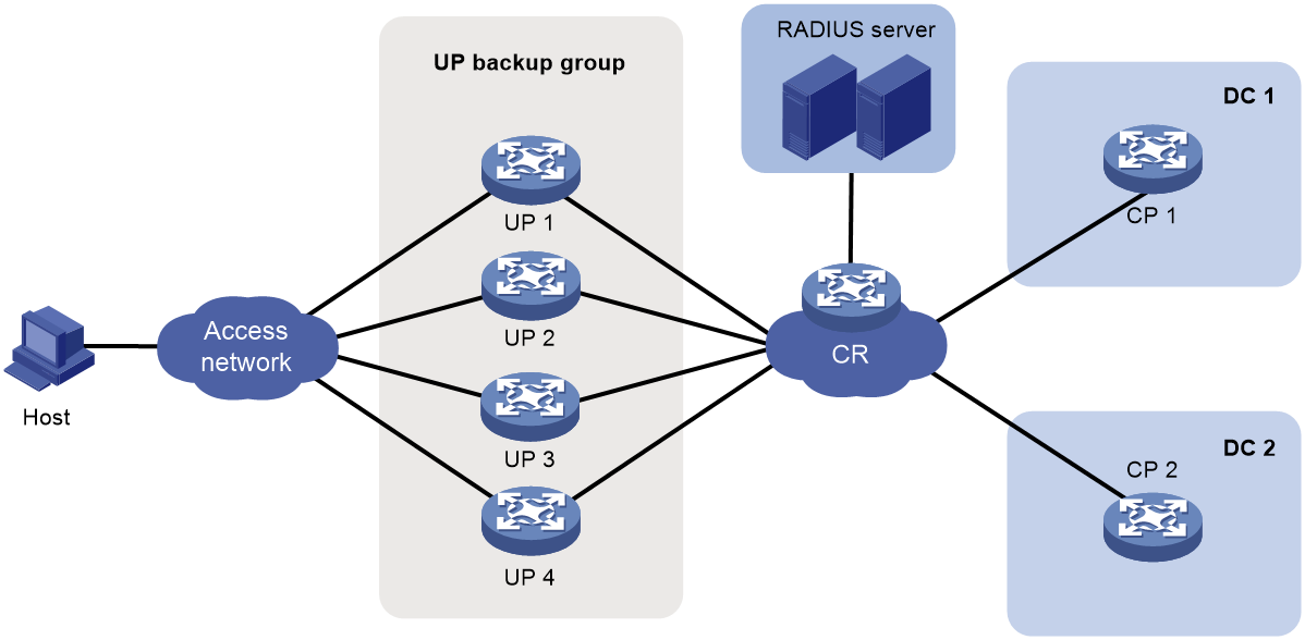
Analysis
For the device to operate in user plane mode, execute the work-mode user-plane command.
To implement CPDR, perform the following tasks:
· On CP 1 and CP 2, create a CPDR group with name g2 and ID 2. Specify the CPDR group as the master on CP 1 and the backup on CP 2.
· Add UPs 1026, 1027, 1028, 1029 to CPDR group g2.
To deploy configurations and service entries to UPs and exchange protocol packets with UPs, configure CP-UP channels.
To implement the UP 1:3 warm standby mode, configure the UP warm load balancing mode.
For users to come online, configure IPoE, AAA, portal, and address pools.
For CPDR, you can use one loopback interface as the CP-UP tunnel interface, the CPDR tunnel interface, and the communication interface between the CP and RADIUS server. This mode features simple configuration. You can also use three different loopback interfaces. This mode features flexible configuration. In this example, one loopback interface is used as both the CP-UP tunnel interface and CPDR tunnel interface. One loopback interface is used as the communication interface between the CP and RADIUS server.
Prerequisites
Configure IP addresses for interfaces, and make sure devices can reach each other at Layer 3.
Configure the AAA server correctly. (Details not shown.)
Configure the portal server correctly. (Details not shown.)
Restrictions and guidelines
Make sure the required configurations, such as CP-UP channel, UP backup, CPDR, AAA, and IPoE, are performed on both CP 1 and CP 2.
The remote interface, address pool, domain, UP backup configurations must be the same on the two CPs.
Procedure
Configuring CPDR settings
1. Configure CP 1:
# Specify local IPv4 address 180.96.185.8 and peer IPv4 address 58.223.243.8 used for establishing CPDR channels.
<CP1> system-view
[CP1] ip vpn-instance CP2UP_L3VPN_H3C
[CP1-vpn-instance CP2UP_L3VPN_H3C] quit
[CP1] cp disaster-recovery tunnel ipv4 local 180.96.185.8 peer 58.223.243.8 vpn-instance CP2UP_L3VPN_H3C
# Create CPDR group g2 and enter CPDR group view.
[CP1] cp disaster-recovery group g2 id 2
# Assign the master role to CPDR group g2.
[CP1-cpdr-group-g2] set role master
# Add UPs 1026, 1027, 1028, 1029 to CPDR group g2.
[CP1-cpdr-group-g2] up-id 1026 1027 1028 1029
# Specify the hot backup mode for CPDR group g2. (The hot backup mode is used by default, and you can skip this configuration.)
[CP1-cpdr-group-g2] mode hot
# Enable automatic role switchover upon CPDR group failure.
[CP1-cpdr-group-g2] switchover auto enable
# Specify the source interface for sending RADIUS packets.
[CP1-cpdr-group-g2] radius source-interface LoopBack3
# Enable strict CU connection failure ratio calculation.
[CP1-cpdr-group-g2] fault-ratio-calculate strict
[CP1-cpdr-group-g2] quit
2. Configure CP 2:
# Specify local IPv4 address 58.223.243.8 and peer IPv4 address 180.96.185.8 used for establishing CPDR channels.
<CP2> system-view
[CP2] ip vpn-instance CP2UP_L3VPN_H3C
[CP2-vpn-instance CP2UP_L3VPN_H3C] quit
[CP2] cp disaster-recovery tunnel ipv4 local 58.223.243.8 peer 180.96.185.8 vpn-instance CP2UP_L3VPN_H3C
# Create CPDR group g2 and enter CPDR group view.
[CP2] cp disaster-recovery group g2 id 2
# Specify CPDR group g1 as the backup CPDR group.
[CP2-cpdr-group-g1] set role backup
# Add UPs 1026, 1027, 1028, 1029 to CPDR group g2.
[CP2-cpdr-group-g2] up-id 1026 1027 1028 1029
# Specify the hot backup mode for CPDR group g2. (The hot backup mode is used by default, and you can skip this configuration.)
[CP2-cpdr-group-g2] mode hot
# Enable automatic role switchover upon CPDR group failure.
[CP2-cpdr-group-g2] switchover auto enable
# Specify the source interface for sending RADIUS packets.
[CP2-cpdr-group-g2] radius source-interface LoopBack3
# Enable strict CU connection failure ratio calculation.
[CP2-cpdr-group-g2] fault-ratio-calculate strict
[CP2-cpdr-group-g2] quit
Configuring CP-UP channels
1. Configure UP 1:
a. Configure the device to operate in user plane mode.
# Configure the device to operate in user plane mode.
<UP1> system-view
[UP1] work-mode user-plane
b. Configure the UP as the NETCONF server.
# Enable the Stelnet server.
[UP1] ssh server enable
# Enable NETCONF over SSH.
[UP1] netconf ssh server enable
# Enable scheme authentication for user lines VTY 0 through VTY 63, through which the NETCONF over SSH clients log in.
[UP1] line vty 0 63
[UP1-line-vty0-63] authentication-mode scheme
[UP1-line-vty0-63] quit
# Add a device management user named admin and set the password to 123456TESTplat&! in plaintext form. Authorize the user to use the SSH service and assign the network-admin user role to the user.
[UP1] local-user admin class manage
[UP1-luser-manage-netconf] password simple 123456TESTplat&!
[UP1-luser-manage-netconf] service-type ssh
[UP1-luser-manage-netconf] authorization-attribute user-role network-admin
[UP1-luser-manage-netconf] quit
# Configure a BFD template. The parameter values are based on the actual network conditions. The BFD template must be configured on both the CPs and UPs.
[UP1] bfd template BFD_CUSP
[UP1-bfd-template-BFD_CUSP] bfd min-transmit-interval 200
[UP1-bfd-template-BFD_CUSP] bfd min-receive-interval 200
[UP1-bfd-template-BFD_CUSP] bfd detect-multiplier 10
[UP1-bfd-template-BFD_CUSP] quit
# Configure the server type as NETCONF and authentication mode as password authentication for SSH user admin.
[UP1] ssh user admin service-type netconf authentication-type password
2. Configure UP 2, UP 3, and UP 4:
# Configure UP 2, UP 3, and UP 4 in the same way UP 1 is configured. (Details not shown.)
3. Configure CP 1:
a. Configure the management channel for the NETCONF client:
# Create a VPN instance. This VPN instance is used for CP-UP communication to prevent attacks from the public network and hide addresses.
<CP1> system-view
[CP1] ip vpn-instance CP2UP_L3VPN_H3C
[CP1-vpn-instance CP2UP_L3VPN_H3C] quit
# Enter NETCONF client view.
[CP1] netconf-client
# Configure the source IP address for setting up a NETCONF connection to a UP.
[CP1-netconf-client] source-address 180.96.185.8
# Create NETCONF connection profile 1026 and enter NETCONF connection profile view.
[CP1-netconf-client] connection 1026
# Specify username admin and password 123456TESTplat&! for the NETCONF connection established between CP 1 and UP 1.
[CP1-netconf-client-connection-1026] user-name admin password simple 123456TESTplat&!
# Enable CP 1 to send NETCONF connection requests to the IP address of UP 1 (2.1. 1.101).
[CP1-netconf-client-connection-1026] destination-address 2.1.1.101 vpn-instance CP2UP_L3VPN_H3C
[CP1-netconf-client-connection-1026] quit
# Create NETCONF connection profile 1027 and enter NETCONF connection profile view.
[CP1-netconf-client] connection 1027
# Specify username admin and password 123456TESTplat&! for the NETCONF connection established between CP 1 and UP 2.
[CP1-netconf-client-connection-1027] user-name admin password simple 123456TESTplat&!
# Enable CP 1 to send NETCONF connection requests to the IP address of UP 2 (2.1.1.102).
[CP1-netconf-client-connection-1027] destination-address 2.1.1.102 vpn-instance CP2UP_L3VPN_H3C
[CP1-netconf-client-connection-1027] quit
# Configure NETCONF connection 1028 and enter NETCONF connection profile view.
[CP1-netconf-client] connection 1028
# Specify username admin and password 123456TESTplat&! for the NETCONF connection established between CP 1 and UP 3.
[CP1-netconf-client-connection-1028] user-name admin password simple 123456TESTplat&!
# Enable CP 1 to send NETCONF connection requests to the IP address of UP 3 (2.1.1.103).
[CP1-netconf-client-connection-1028] destination-address 2.1.1.103 vpn-instance CP2UP_L3VPN_H3C
[CP1-netconf-client-connection-1028] quit
# Create NETCONF connection profile 1029 and enter NETCONF connection profile view.
[CP1-netconf-client] connection 1029
# Specify username admin and password 123456TESTplat&! for the NETCONF connection established between CP 1 and UP 4.
[CP1-netconf-client-connection-1029] user-name admin password simple 123456TESTplat&!
# Enable CP 1 to send NETCONF connection requests to the IP address of UP 4 (2.1.1.104).
[CP1-netconf-client-connection-1029] destination-address 2.1.1.104 vpn-instance CP2UP_L3VPN_H3C
[CP1-netconf-client-connection-1029] quit
[CP1-netconf-client] quit
# Create UP 1026 and enter UP-manage view.
[CP1] up-manage id 1026
# Bind UP 1026 to NETCONF connection profile 1026.
[CP1-up-manage-1026] bind netconf-connection 1026
[CP1-up-manage-1026] quit
# Create UP 1027 and enter UP-manage view.
[CP1] up-manage id 1027
# Bind UP 1027 to NETCONF connection profile 1027.
[CP1-up-manage-1027] bind netconf-connection 1027
[CP1-up-manage-1027] quit
# Create UP 1028 and enter UP-manage view.
[CP1] up-manage id 1028
# Bind UP 1028 to NETCONF connection profile 1028.
[CP1-up-manage-1028] bind netconf-connection 1028
[CP1-up-manage-1028] quit
# Create UP 1029 and enter UP-manage view.
[CP1] up-manage id 1029
# Bind UP 1029 to NETCONF connection profile 1029.
[CP1-up-manage-1029] bind netconf-connection 1029
[CP1-up-manage-1029] quit
b. Configure protocol channels for the CP:
# Configure a protocol channel between CP 1 and UP 1, with VXLAN ID 11026, source IP address 180.96.185.8, and destination IP address 2.1.1.101.
[CP1] up-manage id 1026
[CP1-up-manage-1026] protocol-tunnel vxlan 11026 source 180.96.185.8 destination 2.1.1.101 vpn-instance CP2UP_L3VPN_H3C
[CP1-up-manage-1026] quit
# Configure a protocol channel between CP 1 and UP 2, with VXLAN ID 11027, source IP address 180.96.185.8, and destination IP address 2.1.1.102.
[CP1] up-manage id 1027
[CP1-up-manage-1027] protocol-tunnel vxlan 11027 source 180.96.185.8 destination 2.1.1.102 vpn-instance CP2UP_L3VPN_H3C
[CP1-up-manage-1027] quit
# Configure a protocol channel between CP 1 and UP 3, with VXLAN ID 11028, source IP address 180.96.185.8, and destination IP address 2.1.1.103.
[CP1] up-manage id 1028
[CP1-up-manage-1028] protocol-tunnel vxlan 11028 source 180.96.185.8 destination 2.1.1.103 vpn-instance CP2UP_L3VPN_H3C
[CP1-up-manage-1028] quit
# Configure a protocol channel between CP 1 and UP 4, with VXLAN ID 11029, source IP address 180.96.185.8, and destination IP address 2.1.1.104.
[CP1] up-manage id 1029
[CP1-up-manage-1029] protocol-tunnel vxlan 11029 source 180.96.185.8 destination 2.1.1.104 vpn-instance CP2UP_L3VPN_H3C
[CP1-up-manage-1029] quit
c. Configure protocol channels for UPs:
# Create UP 1026 and enter UP-config view.
[CP1] up-manage id 1026
[CP1-up-manage-1026] up-config
# In CU-agent view, configure a protocol channel between UP 1 and CP 1, with VXLAN ID 11026, source IP address 2.1.1.101, and destination IP address 180.96.185.8. Configure a protocol channel between UP 1 and CP 2, with VXLAN ID 21026, source IP address 2.1.1.101, and destination IP address 58.223.243.8.
[CP1-up-manage-1026-up-config] cu-agent
[CP1-up-manage-1026-up-config-cu-agent] protocol-tunnel vxlan 11026 source 2.1.1.101 destination 180.96.185.8 vpn-instance CP2UP_L3VPN_H3C
[CP1-up-manage-1026-up-config-cu-agent] protocol-tunnel vxlan 21026 source 2.1.1.101 destination 58.223.243.8 vpn-instance CP2UP_L3VPN_H3C
[CP1-up-manage-1026-up-config-cu-agent] quit
[CP1-up-manage-1026-up-config] quit
[CP1-up-manage-1026] quit
# Create UP 1027 and enter UP-config view.
[CP1] up-manage id 1027
[CP1-up-manage-1027] up-config
# In CU-agent view, configure a protocol channel between UP 2 and CP 1, with VXLAN ID 11027, source IP address 2.1.1.102, and destination IP address 180.96.185.8. Configure a protocol channel between UP 2 and CP 2, with VXLAN ID 21027, source IP address 2.1.1.102, and destination IP address 58.223.243.8.
[CP1-up-manage-1027-up-config] cu-agent
[CP1-up-manage-1027-up-config-cu-agent] protocol-tunnel vxlan 11027 source 2.1.1.102 destination 180.96.185.8 vpn-instance CP2UP_L3VPN_H3C
[CP1-up-manage-1027-up-config-cu-agent] protocol-tunnel vxlan 21027 source 2.1.1.102 destination 58.223.243.8 vpn-instance CP2UP_L3VPN_H3C
[CP1-up-manage-1027-up-config-cu-agent] quit
[CP1-up-manage-1027-up-config] quit
[CP1-up-manage-1027] quit
# Create UP 1028 and enter UP-config view.
[CP1] up-manage id 1028
[CP1-up-manage-1028] up-config
# In CU-agent view, configure a protocol channel between UP 3 and CP 1, with VXLAN ID 11028, source IP address 2.1.1.103, and destination IP address 180.96.185.8. Configure a protocol channel between UP 3 and CP 2, with VXLAN ID 21028, source IP address 2.1.1.103, and destination IP address 58.223.243.8.
[CP1-up-manage-1028-up-config] cu-agent
[CP1-up-manage-1028-up-config-cu-agent] protocol-tunnel vxlan 11028 source 2.1.1.103 destination 180.96.185.8 vpn-instance CP2UP_L3VPN_H3C
[CP1-up-manage-1028-up-config-cu-agent] protocol-tunnel vxlan 21028 source 2.1.1.103 destination 58.223.243.8 vpn-instance CP2UP_L3VPN_H3C
[CP1-up-manage-1028-up-config-cu-agent] quit
[CP1-up-manage-1028-up-config] quit
[CP1-up-manage-1028] quit
# Create UP 1029 and enter UP-config view.
[CP1] up-manage id 1029
[CP1-up-manage-1029] up-config
# In CU-agent view, configure a protocol channel between UP 4 and CP 1, with VXLAN ID 11029, source IP address 2.1.1.104, and destination IP address 180.96.185.8. Configure a protocol channel between UP 4 and CP 2, with VXLAN ID 21029, source IP address 2.1.1.104, and destination IP address 58.223.243.8.
[CP1-up-manage-1029-up-config] cu-agent
[CP1-up-manage-1029-up-config-cu-agent] protocol-tunnel vxlan 11029 source 2.1.1.104 destination 180.96.185.8 vpn-instance CP2UP_L3VPN_H3C
[CP1-up-manage-1029-up-config-cu-agent] protocol-tunnel vxlan 21029 source 2.1.1.104 destination 58.223.243.8 vpn-instance CP2UP_L3VPN_H3C
[CP1-up-manage-1029-up-config-cu-agent] quit
[CP1-up-manage-1029-up-config] quit
[CP1-up-manage-1029] quit
d. Configure control channels for the CP:
# Enable the CUSP controller feature and enter CUSP controller view.
[CP1] cusp controller
# Specify the listening IP address as 180.96.185.8 for the CUSP controller.
[CP1-cusp-controller] listening-ip 180.96.185.8
# Enable BFD for CUSP.
[CP1-cusp-controller] bfd enable template BFD_CUSP
# Create CUSP agent up1 and enter CUSP agent view.
[CP1-cusp-controller] agent up1
# Configure the IP address for CUSP agent up1 as 2.1.1.101.
[CP1-cusp-controller-agent-up1] agent-ip 2.1.1.101
[CP1-cusp-controller-agent-up1] quit
# Create CUSP agent up2 and enter CUSP agent view.
[CP1-cusp-controller] agent up2
# Configure the IP address for CUSP agent up2 as 2.1.1.102.
[CP1-cusp-controller-agent-up2] agent-ip 2.1.1.102
[CP1-cusp-controller-agent-up2] quit
# Create CUSP agent up3 and enter CUSP agent view.
[CP1-cusp-controller] agent up3
# Configure the IP address for CUSP agent up3 as 2.1.1.103.
[CP1-cusp-controller-agent-up3] agent-ip 2.1.1.103
[CP1-cusp-controller-agent-up3] quit
# Create CUSP agent up4 and enter CUSP agent view.
[CP1-cusp-controller] agent up4
# Configure the IP address for CUSP agent up4 as 2.1.1.104.
[CP1-cusp-controller-agent-up4] agent-ip 2.1.1.104
[CP1-cusp-controller-agent-up4] quit
[CP1-cusp-controller] quit
# Enable control channel establishment for UP 1026 by using CUSP agent up1.
[CP1] up-manage id 1026
[CP1-up-manage-1026] control-tunnel cusp-agent up1
[CP1-up-manage-1026] quit
# Enable control channel establishment for UP 1027 by using CUSP agent up2.
[CP1] up-manage id 1027
[CP1-up-manage-1027] control-tunnel cusp-agent up2
[CP1-up-manage-1027] quit
# Enable control channel establishment for UP 1028 by using CUSP agent up3.
[CP1] up-manage id 1028
[CP1-up-manage-1028] control-tunnel cusp-agent up3
[CP1-up-manage-1028] quit
# Enable control channel establishment for UP 1029 by using CUSP agent up4.
[CP1] up-manage id 1029
[CP1-up-manage-1029] control-tunnel cusp-agent up4
[CP1-up-manage-1029] quit
e. Configure control channels for UPs:
# Configure a BFD template. The parameter values are based on the actual network conditions. The BFD template must be configured on both the CPs and UPs.
[CP1] bfd template BFD_CUSP
[CP1-bfd-template-BFD_CUSP] bfd min-transmit-interval 200
[CP1-bfd-template-BFD_CUSP] bfd min-receive-interval 200
[CP1-bfd-template-BFD_CUSP] bfd detect-multiplier 10
[CP1-bfd-template-BFD_CUSP] quit
# Enter UP-config view.
[CP1] up-manage id 1026
[CP1-up-manage-1026] up-config
# Create CUSP agent up1 and enter CUSP agent view.
[CP1-up-manage-1026-up-config] cusp agent up1
# Enable UP 1 to establish CUSP connections with CP 1 (180.96.185.8) and CP 2 (58.223.243.8) by using source IP address 2.1.1.101, and enable BFD for CUSP.
[CP1-up-manage-1026-up-config-cusp-agent-up1] local-address 2.1.1.101 vpn-instance CP2UP_L3VPN_H3C
[CP1-up-manage-1026-up-config-cusp-agent-up1] controller address 180.96.185.8
[CP1-up-manage-1026-up-config-cusp-agent-up1] controller address 58.223.243.8
[CP1-up-manage-1026-up-config-cusp-agent-up1] bfd enable template BFD_CUSP
[CP1-up-manage-1026-up-config-cusp-agent-up1] quit
[CP1-up-manage-1026-up-config] quit
[CP1-up-manage-1026] quit
# Enter UP-config view.
[CP1] up-manage id 1027
[CP1-up-manage-1027] up-config
# Create CUSP agent up2 and enter CUSP agent view.
[CP1-up-manage-1027-up-config] cusp agent up2
# Enable UP 2 to establish CUSP connections with CP 1 (180.96.185.8) and CP 2 (58.223.243.8) by using source IP address 2.1.1.102, and enable BFD for CUSP.
[CP1-up-manage-1027-up-config-cusp-agent-up2] local-address 2.1.1.102 vpn-instance CP2UP_L3VPN_H3C
[CP1-up-manage-1027-up-config-cusp-agent-up2] controller address 180.96.185.8
[CP1-up-manage-1027-up-config-cusp-agent-up2] controller address 58.223.243.8
[CP1-up-manage-1027-up-config-cusp-agent-up2] bfd enable template BFD_CUSP
[CP1-up-manage-1027-up-config-cusp-agent-up2] quit
[CP1-up-manage-1027-up-config] quit
[CP1-up-manage-1027] quit
# Enter UP-config view.
[CP1] up-manage id 1028
[CP1-up-manage-1028] up-config
# Create CUSP agent up3 and enter CUSP agent view.
[CP1-up-manage-1028-up-config] cusp agent up3
# Enable UP 3 to establish CUSP connections with CP 1 (180.96.185.8) and CP 2 (58.223.243.8) by using source IP address 2.1.1.103, and enable BFD for CUSP.
[CP1-up-manage-1028-up-config-cusp-agent-up3] local-address 2.1.1.103 vpn-instance CP2UP_L3VPN_H3C
[CP1-up-manage-1028-up-config-cusp-agent-up3] controller address 180.96.185.8
[CP1-up-manage-1028-up-config-cusp-agent-up3] controller address 58.223.243.8
[CP1-up-manage-1028-up-config-cusp-agent-up3] bfd enable template BFD_CUSP
[CP1-up-manage-1028-up-config-cusp-agent-up3] quit
[CP1-up-manage-1028-up-config] quit
[CP1-up-manage-1028] quit
# Enter UP-config view.
[CP1] up-manage id 1029
[CP1-up-manage-1029] up-config
# Create CUSP agent up4 and enter CUSP agent view.
[CP1-up-manage-1029-up-config] cusp agent up4
# Enable UP 4 to establish CUSP connections with CP 1 (180.96.185.8) and CP 2 (58.223.243.8) by using source IP address 2.1.1.104, and enable BFD for CUSP.
[CP1-up-manage-1029-up-config-cusp-agent-up4] local-address 2.1.1.104 vpn-instance CP2UP_L3VPN_H3C
[CP1-up-manage-1029-up-config-cusp-agent-up4] controller address 180.96.185.8
[CP1-up-manage-1029-up-config-cusp-agent-up4] controller address 58.223.243.8
[CP1-up-manage-1029-up-config-cusp-agent-up4] bfd enable template BFD_CUSP
[CP1-up-manage-1029-up-config-cusp-agent-up4] quit
[CP1-up-manage-1029-up-config] quit
[CP1-up-manage-1029] quit
f. Create remote interfaces:
# Create remote UP interface Route-Aggregation701 for UP 1026.
[CP1] up-manage id 1026
[CP1-up-manage-1026] remote interface Route-Aggregation701
[CP1-up-manage-1026] quit
# Create remote UP interface Route-Aggregation701 for UP 1027.
[CP1] up-manage id 1027
[CP1-up-manage-1027] remote interface Route-Aggregation701
[CP1-up-manage-1027] quit
# Create remote UP interface Route-Aggregation701 for UP 1028.
[CP1] up-manage id 1028
[CP1-up-manage-1028] remote interface Route-Aggregation701
[CP1-up-manage-1028] quit
# Create remote UP interface Route-Aggregation701 for UP 1029.
[CP1] up-manage id 1029
[CP1-up-manage-1029] remote interface Route-Aggregation701
[CP1-up-manage-1029] quit
4. Configure CP 2:
a. Configure the management channel for the NETCONF client:
# Create a VPN instance. This VPN instance is used for CP-UP communication to prevent attacks from the public network and hide addresses.
<CP2> system-view
[CP2] ip vpn-instance CP2UP_L3VPN_H3C
[CP2-vpn-instance CP2UP_L3VPN_H3C] quit
# Enter NETCONF client view.
[CP2] netconf-client
# Configure the source IP address for setting up a NETCONF connection to a UP.
[CP2-netconf-client] source-address 58.223.243.8
# Create NETCONF connection profile 1026 and enter NETCONF connection profile view.
[CP2-netconf-client] connection 1026
# Specify username admin and password 123456TESTplat&! for the NETCONF connection established between CP 2 and UP 1.
[CP2-netconf-client-connection-1026] user-name admin password simple 123456TESTplat&!
# Enable CP 2 to send NETCONF connection requests to the IP address of UP 1 (2.1.1.101).
[CP2-netconf-client-connection-1026] destination-address 2.1.1.101 vpn-instance CP2UP_L3VPN_H3C
[CP2-netconf-client-connection-1026] quit
# Create NETCONF connection profile 1027 and enter NETCONF connection profile view.
[CP2-netconf-client] connection 1027
# Specify username admin and password 123456TESTplat&! for the NETCONF connection established between CP 2 and UP 2.
[CP2-netconf-client-connection-1027] user-name admin password simple 123456TESTplat&!
# Enable CP 2 to send NETCONF connection requests to the IP address of UP 2 (2.1.1.102).
[CP2-netconf-client-connection-1027] destination-address 2.1.1.102 vpn-instance CP2UP_L3VPN_H3C
[CP2-netconf-client-connection-1027] quit
# Configure NETCONF connection 1028 and enter NETCONF connection profile view.
[CP2-netconf-client] connection 1028
# Specify username admin and password 123456TESTplat&! for the NETCONF connection established between CP 2 and UP 3.
[CP2-netconf-client-connection-1028] user-name admin password simple 123456TESTplat&!
# Enable CP 2 to send NETCONF connection requests to the IP address of UP 2 (2.1.1.103).
[CP2-netconf-client-connection-1028] destination-address 2.1.1.103 vpn-instance CP2UP_L3VPN_H3C
[CP2-netconf-client-connection-1028] quit
# Create NETCONF connection profile 1029 and enter NETCONF connection profile view.
[CP2-netconf-client] connection 1029
# Specify username admin and password 123456TESTplat&! for the NETCONF connection established between CP 2 and UP 4.
[CP2-netconf-client-connection-1029] user-name admin password simple 123456TESTplat&!
# Enable CP 2 to send NETCONF connection requests to the IP address of UP 4 (2.1.1.104).
[CP2-netconf-client-connection-1029] destination-address 2.1.1.104 vpn-instance CP2UP_L3VPN_H3C
[CP2-netconf-client-connection-1029] quit
[CP2-netconf-client] quit
# Create UP 1026 and enter UP-manage view.
[CP2] up-manage id 1026
# Bind UP 1026 to NETCONF connection profile 1026.
[CP2-up-manage-1026] bind netconf-connection 1026
[CP2-up-manage-1026] quit
# Create UP 1027 and enter UP-manage view.
[CP2] up-manage id 1027
# Bind UP 1027 to NETCONF connection profile 1027.
[CP2-up-manage-1027] bind netconf-connection 1027
[CP2-up-manage-1027] quit
# Create UP 1028 and enter UP-manage view.
[CP2] up-manage id 1028
# Bind UP 1028 to NETCONF connection profile 1028.
[CP2-up-manage-1028] bind netconf-connection 1028
[CP2-up-manage-1028] quit
# Create UP 1029 and enter UP-manage view.
[CP2] up-manage id 1029
# Bind UP 1029 to NETCONF connection profile 1029.
[CP2-up-manage-1029] bind netconf-connection 1029
[CP2-up-manage-1029] quit
b. Configure protocol channels for the CP:
# Configure a protocol channel between CP 2 and UP 1, with VXLAN ID 21026, source IP address 58,223,243.8, and destination IP address 2.1. 1.101.
[CP2] up-manage id 1026
[CP2-up-manage-1026] protocol-tunnel vxlan 21026 source 58.223.243.8 destination 2.1.1.101 vpn-instance CP2UP_L3VPN_H3C
[CP2-up-manage-1026] quit
# Configure a protocol channel between CP 2 and UP 2, with VXLAN ID 21027, source IP address 58,223,243.8, and destination IP address 2.1.1.102.
[CP2] up-manage id 1027
[CP2-up-manage-1027] protocol-tunnel vxlan 21027 source 58.223.243.8 destination 2.1.1.102 vpn-instance CP2UP_L3VPN_H3C
[CP2-up-manage-1027] quit
# Configure a protocol channel between CP 2 and UP 3, with VXLAN ID 21028, source IP address 58,223,243.8, and destination IP address 2.1.1.103.
[CP2] up-manage id 1028
[CP2-up-manage-1028] protocol-tunnel vxlan 21028 source 58.223.243.8 destination 2.1.1.102 vpn-instance CP2UP_L3VPN_H3C
[CP2-up-manage-1028] quit
# Configure a protocol channel between CP 2 and UP 4, with VXLAN ID 21029, source IP address 58,223,243.8, and destination IP address 2.1.1.104.
[CP2] up-manage id 1029
[CP2-up-manage-1029] protocol-tunnel vxlan 21029 source 58.223.243.8 destination 2.1.1.104 vpn-instance CP2UP_L3VPN_H3C
[CP2-up-manage-1029] quit
c. Configure protocol channels for UPs:
# Create UP 1026 and enter UP-config view.
[CP2] up-manage id 1026
[CP2-up-manage-1026] up-config
# In CU-agent view, configure a protocol channel between UP 1 and CP 1, with VXLAN ID 11026, source IP address 2.1.1.101, and destination IP address 180.96.185.8. Configure a protocol channel between UP 1 and CP 2, with VXLAN ID 21026, source IP address 2.1.1.101, and destination IP address 58.223.243.8.
[CP2-up-manage-1026-up-config] cu-agent
[CP2-up-manage-1026-up-config-cu-agent] protocol-tunnel vxlan 11026 source 2.1.1.101 destination 180.96.185.8 vpn-instance CP2UP_L3VPN_H3C
[CP2-up-manage-1026-up-config-cu-agent] protocol-tunnel vxlan 21026 source 2.1.1.101 destination 58.223.243.8 vpn-instance CP2UP_L3VPN_H3C
[CP2-up-manage-1026-up-config-cu-agent] quit
[CP2-up-manage-1026-up-config] quit
[CP2-up-manage-1026] quit
# Create UP 1027 and enter UP-config view.
[CP2] up-manage id 1027
[CP2-up-manage-1027] up-config
# In CU-agent view, configure a protocol channel between UP 2 and CP 1, with VXLAN ID 11027, source IP address 2.1.1.102, and destination IP address 180.96.185.8. Configure a protocol channel between UP 2 and CP 2, with VXLAN ID 21027, source IP address 2.1.1.102, and destination IP address 58.223.243.8.
[CP2-up-manage-1027-up-config] cu-agent
[CP2-up-manage-1027-up-config-cu-agent] protocol-tunnel vxlan 11027 source 2.1.1.102 destination 180.96.185.8 vpn-instance CP2UP_L3VPN_H3C
[CP2-up-manage-1027-up-config-cu-agent] protocol-tunnel vxlan 21027 source 2.1.1.102 destination 58.223.243.8 vpn-instance CP2UP_L3VPN_H3C
[CP2-up-manage-1027-up-config-cu-agent] quit
[CP2-up-manage-1027-up-config] quit
[CP2-up-manage-1027] quit
# Create UP 1028 and enter UP-config view.
[CP2] up-manage id 1028
[CP2-up-manage-1028] up-config
# In CU-agent view, configure a protocol channel between UP 3 and CP 1, with VXLAN ID 11028, source IP address 2.1.1.103, and destination IP address 180.96.185.8. Configure a protocol channel between UP 3 and CP 2, with VXLAN ID 21028, source IP address 2.1.1.103, and destination IP address 58.223.243.8.
[CP2-up-manage-1028-up-config] cu-agent
[CP2-up-manage-1028-up-config-cu-agent] protocol-tunnel vxlan 11028 source 2.1.1.103 destination 180.96.185.8 vpn-instance CP2UP_L3VPN_H3C
[CP2-up-manage-1028-up-config-cu-agent] protocol-tunnel vxlan 21028 source 2.1.1.103 destination 58.223.243.8 vpn-instance CP2UP_L3VPN_H3C
[CP2-up-manage-1028-up-config-cu-agent] quit
[CP2-up-manage-1028-up-config] quit
[CP2-up-manage-1028] quit
# Create UP 1029 and enter UP-config view.
[CP2] up-manage id 1029
[CP2-up-manage-1029] up-config
# In CU-agent view, configure a protocol channel between UP 4 and CP 1, with VXLAN ID 11029, source IP address 2.1.1.104, and destination IP address 180.96.185.8. Configure a protocol channel between UP 4 and CP 2, with VXLAN ID 21029, source IP address 2.1.1.104, and destination IP address 58.223.243.8.
[CP2-up-manage-1029-up-config] cu-agent
[CP2-up-manage-1029-up-config-cu-agent] protocol-tunnel vxlan 11029 source 2.1.1.104 destination 180.96.185.8 vpn-instance CP2UP_L3VPN_H3C
[CP2-up-manage-1029-up-config-cu-agent] protocol-tunnel vxlan 21029 source 2.1.1.104 destination 58.223.243.8 vpn-instance CP2UP_L3VPN_H3C
[CP2-up-manage-1029-up-config-cu-agent] quit
[CP2-up-manage-1029-up-config] quit
[CP2-up-manage-1029] quit
d. Configure the control channel for the CP:
# Enable the CUSP controller feature and enter CUSP controller view.
[CP2] cusp controller
# Specify the listening IP address as 58.223.243.8 for the CUSP controller, and enable BFD for CUSP.
[CP2-cusp-controller] listening-ip 58.223.243.8 vpn-instance CP2UP_L3VPN_H3C
[CP2-cusp-controller] bfd enable template BFD_CUSP
# Create CUSP agent up1 and enter CUSP agent view.
[CP2-cusp-controller] agent up1
# Configure the IP address for CUSP agent up1 as 2.1. 1.101.
[CP2-cusp-controller-agent-up1] agent-ip 2.1.1.101
[CP2-cusp-controller-agent-up1] quit
# Create CUSP agent up2 and enter CUSP agent view.
[CP2-cusp-controller] agent up2
# Configure the IP address for CUSP agent up2 as 2.1.1.102.
[CP2-cusp-controller-agent-up2] agent-ip 2.1.1.102
[CP2-cusp-controller-agent-up2] quit
# Create CUSP agent up3 and enter CUSP agent view.
[CP2-cusp-controller] agent up3
# Configure the IP address for CUSP agent up3 as 2.1.1.103.
[CP2-cusp-controller-agent-up3] agent-ip 2.1.1.103
[CP2-cusp-controller-agent-up3] quit
# Create CUSP agent up4 and enter CUSP agent view.
[CP2-cusp-controller] agent up4
# Configure the IP address for CUSP agent up4 as 2.1.1.104.
[CP2-cusp-controller-agent-up4] agent-ip 2.1.1.104
[CP2-cusp-controller-agent-up4] quit
[CP2-cusp-controller] quit
# Enable control channel establishment for UP 1026 by using CUSP agent up1.
[CP2] up-manage id 1026
[CP2-up-manage-1026] control-tunnel cusp-agent up1
[CP2-up-manage-1026] quit
# Enable control channel establishment for UP 1027 by using CUSP agent up2.
[CP2] up-manage id 1027
[CP2-up-manage-1027] control-tunnel cusp-agent up2
[CP2-up-manage-1027] quit
# Enable control channel establishment for UP 1028 by using CUSP agent up3.
[CP2] up-manage id 1028
[CP2-up-manage-1028] control-tunnel cusp-agent up3
[CP2-up-manage-1028] quit
# Enable control channel establishment for UP 1029 by using CUSP agent up4.
[CP2] up-manage id 1029
[CP2-up-manage-1029] control-tunnel cusp-agent up4
[CP2-up-manage-1029] quit
e. Configure the control channel for UPs:
# Configure a BFD template. The parameter values are based on the actual network conditions. The BFD template must be configured on both the CP and UPs.
[CP2] bfd template BFD_CUSP
[CP2-bfd-template-BFD_CUSP] bfd min-transmit-interval 200
[CP2-bfd-template-BFD_CUSP] bfd min-receive-interval 200
[CP2-bfd-template-BFD_CUSP] bfd detect-multiplier 10
[CP2-bfd-template-BFD_CUSP] quit
# Enter UP-config view.
[CP2] up-manage id 1026
[CP2-up-manage-1026] up-config
# Create CUSP agent up1 and enter CUSP agent view.
[CP2-up-manage-1026-up-config] cusp agent up1
# Enable UP 1 to establish CUSP connections with CP 1 (180.96.185.8) and CP 2 (58.223.243.8) by using source IP address 2.1.1.101, and enable BFD for CUSP.
[CP2-up-manage-1026-up-config-cusp-agent-up1] local-address 2.1.1.101 vpn-instance CP2UP_L3VPN_H3C
[CP2-up-manage-1026-up-config-cusp-agent-up1] controller address 180.96.185.8
[CP2-up-manage-1026-up-config-cusp-agent-up1] controller address 58.223.243.8
[CP2-up-manage-1026-up-config-cusp-agent-up1] bfd enable template BFD_CUSP
[CP2-up-manage-1026-up-config-cusp-agent-up1] quit
[CP2-up-manage-1026-up-config] quit
[CP2-up-manage-1026] quit
# Enter UP-config view.
[CP2] up-manage id 1027
[CP2-up-manage-1027] up-config
# Create CUSP agent up2 and enter CUSP agent view.
[CP2-up-manage-1027-up-config] cusp agent up2
# Enable UP 2 to establish CUSP connections with CP 1 (180.96.185.8) and CP 2 (58.223.243.8) by using source IP address 2.1.1.102, and enable BFD for CUSP.
[CP2-up-manage-1027-up-config-cusp-agent-up1] local-address 2.1.1.102 vpn-instance CP2UP_L3VPN_H3C
[CP2-up-manage-1027-up-config-cusp-agent-up1] controller address 180.96.185.8
[CP2-up-manage-1027-up-config-cusp-agent-up1] controller address 58.223.243.8
[CP2-up-manage-1027-up-config-cusp-agent-up1] bfd enable template BFD_CUSP
[CP2-up-manage-1027-up-config-cusp-agent-up1] quit
[CP2-up-manage-1027-up-config] quit
[CP2-up-manage-1027] quit
# Enter UP-config view.
[CP2] up-manage id 1028
[CP2-up-manage-1028] up-config
# Create CUSP agent up3 and enter CUSP agent view.
[CP2-up-manage-1028-up-config] cusp agent up3
# Enable UP 3 to establish CUSP connections with CP 1 (180.96.185.8) and CP 2 (58.223.243.8) by using source IP address 2.1.1.103, and enable BFD for CUSP.
[CP2-up-manage-1028-up-config-cusp-agent-up1] local-address 2.1.1.103 vpn-instance CP2UP_L3VPN_H3C
[CP2-up-manage-1028-up-config-cusp-agent-up1] controller address 180.96.185.8
[CP2-up-manage-1028-up-config-cusp-agent-up1] controller address 58.223.243.8
[CP2-up-manage-1028-up-config-cusp-agent-up1] bfd enable template BFD_CUSP
[CP2-up-manage-1028-up-config-cusp-agent-up1] quit
[CP2-up-manage-1028-up-config] quit
[CP2-up-manage-1028] quit
# Enter UP-config view.
[CP2] up-manage id 1029
[CP2-up-manage-1029] up-config
# Create CUSP agent up4 and enter CUSP agent view.
[CP2-up-manage-1029-up-config] cusp agent up4
# Enable UP 4 to establish CUSP connections with CP 1 (180.96.185.8) and CP 2 (58.223.243.8) by using source IP address 2.1.1.104, and enable BFD for CUSP.
[CP2-up-manage-1029-up-config-cusp-agent-up4] local-address 2.1.1.104 vpn-instance CP2UP_L3VPN_H3C
[CP2-up-manage-1029-up-config-cusp-agent-up4] controller address 180.96.185.8
[CP2-up-manage-1029-up-config-cusp-agent-up4] controller address 58.223.243.8
[CP2-up-manage-1029-up-config-cusp-agent-up4] bfd enable template BFD_CUSP
[CP2-up-manage-1029-up-config-cusp-agent-up4] quit
[CP2-up-manage-1029-up-config] quit
[CP2-up-manage-1029] quit
f. Create remote interfaces:
# Create remote UP interface Route-Aggregation701 for UP 1026.
[CP2] up-manage id 1026
[CP2-up-manage-1026] remote interface Route-Aggregation701
[CP2-up-manage-1026] quit
# Create remote UP interface Route-Aggregation701 for UP 1027.
[CP2] up-manage id 1027
[CP2-up-manage-1027] remote interface Route-Aggregation701
[CP2-up-manage-1027] quit
# Create remote UP interface Route-Aggregation701 for UP 1028.
[CP2] up-manage id 1028
[CP2-up-manage-1028] remote interface Route-Aggregation701
[CP2-up-manage-1028] quit
# Create remote UP interface Route-Aggregation701 for UP 1029.
[CP2] up-manage id 1029
[CP2-up-manage-1029] remote interface Route-Aggregation701
[CP2-up-manage-1029] quit
Configuring UP backup
1. Configure CP 1:
a. Configure a UP backup group.
[CP1] up-backup-group group2
[CP1-up-backup-group-group2] backup up-id 1026
[CP1-up-backup-group-group2] backup up-id 1027
[CP1-up-backup-group-group2] backup up-id 1028
[CP1-up-backup-group-group2] backup up-id 1029
[CP1-up-backup-group-group2] quit
b. Configure a UP backup profile:
# Create UP backup profile 2 in warm standby mode.
[CP1] up-backup-profile 2 warm-load-balance
# Specify master interfaces for the UP backup profile.
[CP1-up-backup-profile-2] master-interface Remote-RAGG1026/701 vrid 1
[CP1-up-backup-profile-2] master-interface Remote-RAGG1027/701 vrid 2
[CP1-up-backup-profile-2] master-interface Remote-RAGG1028/701 vrid 3
[CP1-up-backup-profile-2] master-interface Remote-RAGG1029/701 vrid 4
# Specify the interface-based method to select master interfaces and load balances traffic based on the outer VLAN and inner VLAN.
[CP1-up-backup-profile-2] load-balance-mode interface by-qinq
# Disable the original master UP or interface from switching back to master upon failure recovery.
[CP1-up-backup-profile-2] undo failure-recovery-switch enable
# Configure the logical access interface for UP backup profile 1 as Remote-RAGG1026/701. When the CP sends RADIUS packets to the RADIUS server, it adds the logical access interface specified in this command to the NAS-Port-ID attribute in the RADIUS packets.
[CP1-up-backup-profile-2] nas logic-port Remote-RAGG1026/701
# Configure the switchover delay upon CUSP channel failure as 5 seconds.
[CP1-up-backup-profile-2] control-tunnel-down switchover delay 5
# Configure the switchover delay upon CUSP channel failure recovery as 60000 milliseconds.
[CP1-up-backup-profile-2] control-tunnel-up switchover msec-delay 60000
2. Configure CP 2:
Configure CP 2 in the same way CP 1 is configured. (Details not shown.)
Configuring CGN
1. Configure CGN on CP 1 and CP 2:
a. Configure NAT instances and user groups on CPs:
# Configure the NAT instance name and user group name on the CP, ensuring the instance name and ID match those on the UP side. The user group configured on the CP will be deployed to all UPs.
[CP1] nat instance CGN-A id 1
[CP1-nat-instance-CGN-A] quit
[CP1] user-group cgn-a
[CP1-ugroup-cgn-a] quit
[CP1] user-group web-a
[CP1-ugroup-web-a] quit
[CP1] nat instance CGN-B id 2
[CP1-nat-instance-CGN-B] quit
[CP1] user-group cgn-b
[CP1-ugroup-cgn-b] quit
[CP1] user-group web-b
[CP1-ugroup-web-b] quit
2. Configure CGN on UP 1:
a. Configure failover groups:
# Assign CPU 0 on the CGN card in slot 5 and CPU 0 on the CGN card in slot 6 to the failover groups.
[UP1] failover group cgn1 id 1
[UP1-failover-group-cgn1] bind slot 5 cpu 0 primary
[UP1-failover-group-cgn1] bind slot 6 cpu 0 secondary
[UP1-failover-group-cgn1] quit
[UP1] failover group cgn2 id 2
[UP1-failover-group-cgn2] bind slot 6 cpu 0 primary
[UP1-failover-group-cgn2] bind slot 5 cpu 0 secondary
[UP1-failover-group-cgn2] quit
b. Configure service instance groups.
[UP1] service-instance-group CGN-A
[UP1-service-instance-group-CGN-A] failover-group cgn1
[UP1-service-instance-group-CGN-A] quit
[UP1] service-instance-group CGN-B
[UP1-service-instance-group-CGN-B] failover-group cgn2
[UP1-service-instance-group-CGN-B] quit
c. Configure NAT address groups:
# Specify the port range as 1024 to 65535 for a NAT address group and set the port block size to 4096, allowing one public address to be used for 15 private network users.
[UP1] nat address-group 1
[UP1-address-group-1] port-range 1024 65535
[UP1-address-group-1] port-block block-size 4096
[UP1-address-group-1] quit
[UP1] nat address-group 2
[UP1-address-group-2] port-range 1024 65535
[UP1-address-group-2] port-block block-size 4096
[UP1-address-group-2] quit
Tip: The port range for a public network address contains 64512 ports, and the port block for a single user contains 4096 ports. This allows 15 users to share 61440 ports (15 users * 4096 ports/user = 61440 ports), leaving 3072 ports (64512 - 61440 = 3072 ports) which are insufficient for allocating to another full user and are thus considered unusable.
d. Configure NAT IP pools:
[UP1] nat ip-pool public-01-A dynamic
# Bind the NAT IP pool to public-group, the public network address pool configured on the CP.
[UP1-nat-ip-pool-public-01-A] bind dhcp-server-pool public-group
# Set the subnet acquisition and release thresholds in the global address pool.
[UP1-nat-ip-pool-public-01-A] ip-usage-threshold upper-limit 100 lower-limit 90
[UP1-nat-ip-pool-public-01-A] quit
[UP1] nat ip-pool public-01-B dynamic
[UP1-nat-ip-pool-public-01-B] bind dhcp-server-pool public-group
[UP1-nat-ip-pool-public-01-B] ip-usage-threshold upper-limit 100 lower-limit 90
[UP1-nat-ip-pool-public-01-B] quit
e. Create ACL rules.
[UP1] acl advanced 3320
[UP1-acl-ipv4-adv-3320] rule 5 permit ip user-group cgn-a
[UP1-acl-ipv4-adv-3320] rule 10 permit ip user-group web-a
[UP1-acl-ipv4-adv-3320] quit
[UP1] acl advanced 3321
[UP1-acl-ipv4-adv-3321] rule 5 permit ip user-group cgn-b
[UP1-acl-ipv4-adv-3321] rule 10 permit ip user-group web-b
[UP1-acl-ipv4-adv-3321] quit
f. Configure NAT instances.
[UP1] nat instance CGN-A id 1
[UP1-nat-instance-CGN-A] service-instance-group CGN-A
[UP1-nat-instance-CGN-A] nat outbound 3320 address-group 1
[UP1-nat-instance-CGN-A] nat address-group 1 bind-ip-pool public-01-A
[UP1-nat-instance-CGN-A] quit
[UP1] nat instance CGN-B id 2
[UP1-nat-instance-CGN-B] service-instance-group CGN-B
[UP1-nat-instance-CGN-B] nat outbound 3321 address-group 2
[UP1-nat-instance-CGN-B] nat address-group 2 bind-ip-pool public-01-B
[UP1-nat-instance-CGN-B] quit
3. Configure CGN on UP 2:
a. Configure failover groups.
# Assign CPU 0 on the CGN card in slot 5 and CPU 0 on the CGN card in slot 6 to the failover groups.
[UP2] failover group cgn1 id 1
[UP2-failover-group-cgn1] bind slot 5 cpu 0 primary
[UP2-failover-group-cgn1] bind slot 6 cpu 0 secondary
[UP2-failover-group-cgn1] quit
[UP2] failover group cgn2 id 2
[UP2-failover-group-cgn2] bind slot 6 cpu 0 primary
[UP2-failover-group-cgn2] bind slot 5 cpu 0 secondary
[UP2-failover-group-cgn2] quit
b. Configure service instance groups.
[UP2] service-instance-group CGN-A
[UP2-service-instance-group-CGN-A] failover-group cgn1
[UP2-service-instance-group-CGN-A] quit
[UP2] service-instance-group CGN-B
[UP2-service-instance-group-CGN-B] failover-group cgn2
[UP2-service-instance-group-CGN-B] quit
c. Configure NAT address groups:
# Specify the port range as 1024 to 65535 for a NAT address group and set the port block size to 4096, allowing one public address to be used for 15 private network users.
[UP2] nat address-group 1
[UP2-address-group-1] port-range 1024 65535
[UP2-address-group-1] port-block block-size 4096
[UP2-address-group-1] quit
[UP2] nat address-group 2
[UP2-address-group-2] port-range 1024 65535
[UP2-address-group-2] port-block block-size 4096
[UP2-address-group-2] quit
d. Configure NAT IP pools:
[UP2] nat ip-pool public-01-A dynamic
# Bind the NAT IP pool to public-group, the public network address pool configured on the CP.
[UP2-nat-ip-pool-public-01-A] bind dhcp-server-pool public-group
# Set the subnet acquisition and release thresholds in the global address pool.
[UP2-nat-ip-pool-public-01-A] ip-usage-threshold upper-limit 100 lower-limit 90
[UP2-nat-ip-pool-public-01-A] quit
[UP2] nat ip-pool public-01-B dynamic
[UP2-nat-ip-pool-public-01-B] bind dhcp-server-pool public-group
[UP2-nat-ip-pool-public-01-B] ip-usage-threshold upper-limit 100 lower-limit 90
[UP2-nat-ip-pool-public-01-B] quit
e. Create ACL rules.
[UP2] acl advanced 3320
[UP2-acl-ipv4-adv-3320] rule 5 permit ip user-group cgn-a
[UP2-acl-ipv4-adv-3320] rule 10 permit ip user-group web-a
[UP2-acl-ipv4-adv-3320] quit
[UP2] acl advanced 3321
[UP2-acl-ipv4-adv-3321] rule 5 permit ip user-group cgn-b
[UP2-acl-ipv4-adv-3321] rule 10 permit ip user-group web-b
[UP2-acl-ipv4-adv-3321] quit
f. Configure NAT instances.
[UP2] nat instance CGN-A id 1
[UP2-nat-instance-CGN-A] service-instance-group CGN-A
[UP2-nat-instance-CGN-A] nat outbound 3320 address-group 1
[UP2-nat-instance-CGN-A] nat address-group 1 bind-ip-pool public-01-A
[UP2-nat-instance-CGN-A] quit
[UP2] nat instance CGN-B id 2
[UP2-nat-instance-CGN-B] service-instance-group CGN-B
[UP2-nat-instance-CGN-B] nat outbound 3321 address-group 2
[UP2-nat-instance-CGN-B] nat address-group 2 bind-ip-pool public-01-B
[UP2-nat-instance-CGN-B] quit
4. Configure CGN on UP 3:
a. Configure failover groups.
# Assign CPU 0 on the CGN card in slot 5 and CPU 0 on the CGN card in slot 6 to the failover groups.
[UP3] failover group cgn1 id 1
[UP3-failover-group-cgn1] bind slot 5 cpu 0 primary
[UP3-failover-group-cgn1] bind slot 6 cpu 0 secondary
[UP3-failover-group-cgn1] quit
[UP3] failover group cgn2 id 2
[UP3-failover-group-cgn2] bind slot 6 cpu 0 primary
[UP3-failover-group-cgn2] bind slot 5 cpu 0 secondary
[UP3-failover-group-cgn2] quit
b. Configure service instance groups.
[UP3] service-instance-group CGN-A
[UP3-service-instance-group-CGN-A] failover-group cgn1
[UP3-service-instance-group-CGN-A] quit
[UP3] service-instance-group CGN-B
[UP3-service-instance-group-CGN-B] failover-group cgn2
[UP3-service-instance-group-CGN-B] quit
c. Configure NAT address groups:
# Specify the port range as 1024 to 65535 for a NAT address group and set the port block size to 4096, allowing one public address to be used for 15 private network users.
[UP3] nat address-group 1
[UP3-address-group-1] port-range 1024 65535
[UP3-address-group-1] port-block block-size 4096
[UP3-address-group-1] quit
[UP3] nat address-group 2
[UP3-address-group-2] port-range 1024 65535
[UP3-address-group-2] port-block block-size 4096
[UP3-address-group-2] quit
d. Configure NAT IP pools:
[UP3] nat ip-pool public-01-A dynamic
# Bind the NAT IP pool to public-group, the public network address pool configured on the CP.
[UP3-nat-ip-pool-public-01-A] bind dhcp-server-pool public-group
# Set the subnet acquisition and release thresholds in the global address pool.
[UP3-nat-ip-pool-public-01-A] ip-usage-threshold upper-limit 100 lower-limit 90
[UP3-nat-ip-pool-public-01-A] quit
[UP3] nat ip-pool public-01-B dynamic
[UP3-nat-ip-pool-public-01-B] bind dhcp-server-pool public-group
[UP3-nat-ip-pool-public-01-B] ip-usage-threshold upper-limit 100 lower-limit 90
[UP3-nat-ip-pool-public-01-B] quit
e. Create ACL rules.
[UP3] acl advanced 3320
[UP3-acl-ipv4-adv-3320] rule 5 permit ip user-group cgn-a
[UP3-acl-ipv4-adv-3320] rule 10 permit ip user-group web-a
[UP3-acl-ipv4-adv-3320] quit
[UP3] acl advanced 3321
[UP3-acl-ipv4-adv-3321] rule 5 permit ip user-group cgn-b
[UP3-acl-ipv4-adv-3321] rule 10 permit ip user-group web-b
[UP3-acl-ipv4-adv-3321] quit
f. Configure NAT instances.
[UP3] nat instance CGN-A id 1
[UP3-nat-instance-CGN-A] service-instance-group CGN-A
[UP3-nat-instance-CGN-A] nat outbound 3320 address-group 1
[UP3-nat-instance-CGN-A] nat address-group 1 bind-ip-pool public-01-A
[UP3-nat-instance-CGN-A] quit
[UP3] nat instance CGN-B id 2
[UP3-nat-instance-CGN-B] service-instance-group CGN-B
[UP3-nat-instance-CGN-B] nat outbound 3321 address-group 2
[UP3-nat-instance-CGN-B] nat address-group 2 bind-ip-pool public-01-B
[UP3-nat-instance-CGN-B] quit
5. Configure CGN on UP 4:
a. Configure failover groups.
# Assign CPU 0 on the CGN card in slot 5 and CPU 0 on the CGN card in slot 6 to the failover groups.
[UP4] failover group cgn1 id 1
[UP4-failover-group-cgn1] bind slot 5 cpu 0 primary
[UP4-failover-group-cgn1] bind slot 6 cpu 0 secondary
[UP4-failover-group-cgn1] quit
[UP4] failover group cgn2 id 2
[UP4-failover-group-cgn2] bind slot 6 cpu 0 primary
[UP4-failover-group-cgn2] bind slot 5 cpu 0 secondary
[UP4-failover-group-cgn2] quit
b. Configure service instance groups.
[UP4] service-instance-group CGN-A
[UP4-service-instance-group-CGN-A] failover-group cgn1
[UP4-service-instance-group-CGN-A] quit
[UP4] service-instance-group CGN-B
[UP4-service-instance-group-CGN-B] failover-group cgn2
[UP4-service-instance-group-CGN-B] quit
c. Configure NAT address groups.
# Specify the port range as 1024 to 65535 for a NAT address group and set the port block size to 4096, allowing one public address to be used for 15 private network users.
[UP4] nat address-group 1
[UP4-address-group-1] port-range 1024 65535
[UP4-address-group-1] port-block block-size 4096
[UP4-address-group-1] quit
[UP4] nat address-group 2
[UP4-address-group-2] port-range 1024 65535
[UP4-address-group-2] port-block block-size 4096
[UP4-address-group-2] quit
d. Configure NAT IP pools:
[UP4] nat ip-pool public-01-A dynamic
# Bind the NAT IP pool to public-group, the public network address pool configured on the CP.
[UP4-nat-ip-pool-public-01-A] bind dhcp-server-pool public-group
# Set the subnet acquisition and release thresholds in the global address pool.
[UP4-nat-ip-pool-public-01-A] ip-usage-threshold upper-limit 100 lower-limit 90
[UP4-nat-ip-pool-public-01-A] quit
[UP4] nat ip-pool public-01-B dynamic
[UP4-nat-ip-pool-public-01-B] bind dhcp-server-pool public-group
[UP4-nat-ip-pool-public-01-B] ip-usage-threshold upper-limit 100 lower-limit 90
[UP4-nat-ip-pool-public-01-B] quit
e. Create ACL rules.
[UP4] acl advanced 3320
[UP4-acl-ipv4-adv-3320] rule 5 permit ip user-group cgn-a
[UP4-acl-ipv4-adv-3320] rule 10 permit ip user-group web-a
[UP4-acl-ipv4-adv-3320] quit
[UP4] acl advanced 3321
[UP4-acl-ipv4-adv-3321] rule 5 permit ip user-group cgn-b
[UP4-acl-ipv4-adv-3321] rule 10 permit ip user-group web-b
[UP4-acl-ipv4-adv-3321] quit
f. Configure NAT instances.
[UP4] nat instance CGN-A id 1
[UP4-nat-instance-CGN-A] service-instance-group CGN-A
[UP4-nat-instance-CGN-A] nat outbound 3320 address-group 1
[UP4-nat-instance-CGN-A] nat address-group 1 bind-ip-pool public-01-A
[UP4-nat-instance-CGN-A] quit
[UP4] nat instance CGN-B id 2
[UP4-nat-instance-CGN-B] service-instance-group CGN-B
[UP4-nat-instance-CGN-B] nat outbound 3321 address-group 2
[UP4-nat-instance-CGN-B] nat address-group 2 bind-ip-pool public-01-B
[UP4-nat-instance-CGN-B] quit
Configuring UP monitoring
1. Configure UP 1:
# Create a static BFD session and enter its view. The static BFD session detects the next-hop address for the network-side interface and two output interfaces for the next hop.
[UP1] bfd static up1toSLEAF1 peer-ipv6 2:1:1::5 source-ipv6 2:1:1::101 discriminator auto
[UP1-bfd-static-session-up1oSLEAF1] bfd multi-hop detect-multiplier 10
[UP1-bfd-static-session-up1oSLEAF1] quit
[UP1] bfd static up1toSLEAF2 peer-ipv6 2:1:1::6 source-ipv6 2:1:1::101 discriminator auto
[UP1-bfd-static-session-up1oSLEAF2] bfd multi-hop detect-multiplier 10
[UP1-bfd-static-session-up1oSLEAF2] quit
[UP1] track 1 bfd static up1oSLEAF1
[UP1] track 2 bfd static up1oSLEAF2
[UP1-track-1] quit
# Create Boolean OR list 5 and enter its view. Add track entries 1 and 2 as tracked objects to the list.
[UP1] track 5 list boolean or
[UP1-track-5] object 1
[UP1-track-5] object 2
[UP1-track-5] quit
# Disable master/backup interface switchover on the UP, and specify track entry 5 to monitor the link between the UP and the upstream router.
[UP1] user-plane control-tunnel-down switchover track 5
# Configure network-side bandwidth detection.
[UP1] track 12 bfd echo interface HundredGigE2/2/1 remote ipv6 176:1:1:13::7 local ipv6 176:1:1:13::6
[UP1] track 13 bfd echo interface HundredGigE2/1/1 remote ipv6 176:1:1:2::3 local ipv6 176:1:1:2::2
[UP1] track 14 bfd echo interface HundredGigE4/2/1 remote ipv6 176:1:1:1::3 local ipv6 176:1:1:1::2
[UP1] track 15 bfd echo interface HundredGigE4/1/1 remote ipv6 176:1:1:13::3 local ipv6 176:1:1:13::2
# Create a percentage threshold list and enter its view. Set the negative state threshold to 49% and the positive state threshold to 50% for the percentage threshold list.
[UP1] track 16 list threshold percentage
[UP1-track-16] threshold percentage negative 49 positive 50
[UP1-track-16] object 12
[UP1-track-16] object 13
[UP1-track-16] object 14
[UP1-track-16] object 15
[UP1-track-16] quit
# Create Boolean AND list 11 and enter its view. Add track entry 16 as a tracked object to the list.
[UP1] track 11 list boolean and
[UP1-track-11] object 16
[UP1-track-11] quit
# Associate the UP with track entry 11.
[UP1] user-plane switchover track 11 uplink-group JH-CN-PUP1026
2. Configure UP 2:
# Create a static BFD session and enter its view. The static BFD session detects the next-hop address for the network-side interface.
[UP2] bfd static up2toSLEAF1 peer-ipv6 2:1:1::5 source-ipv6 2:1:1::102 discriminator auto
[UP2-bfd-static-session-up2toSLEAF1] bfd multi-hop detect-multiplier 10
[UP2-bfd-static-session-up2toSLEAF1] quit
[UP2] bfd static up2toSLEAF2 peer-ipv6 2:1:1::6 source-ipv6 2:1:1::102 discriminator auto
[UP2-bfd-static-session-up2toSLEAF2] bfd multi-hop detect-multiplier 10
[UP2-bfd-static-session-up2toSLEAF2] quit
[UP2] track 1 bfd static up2toSLEAF1
[UP2] track 2 bfd static up2toSLEAF2
[UP2-track-1] quit
# Create Boolean OR list 5 and enter its view. Add track entries 1 and 2 as tracked objects to the list.
[UP2] track 5 list boolean or
[UP2-track-5] object 1
[UP2-track-5] object 2
[UP2-track-5] quit
# Disable master/backup interface switchover on the UP, and specify track entry 5 to monitor the link between the UP and the upstream router.
[UP2] user-plane control-tunnel-down switchover track 5
# Configure network-side bandwidth detection.
[UP2] track 12 bfd echo interface HundredGigE2/2/1 remote ipv6 176:2:1:13::7 local ipv6 176:2:1:13::6
[UP2] track 13 bfd echo interface HundredGigE2/1/1 remote ipv6 176:2:1:2::3 local ipv6 176:2:1:2::2
[UP2] track 14 bfd echo interface HundredGigE4/2/1 remote ipv6 176:2:1:1::3 local ipv6 176:2:1:1::2
[UP2] track 15 bfd echo interface HundredGigE4/1/1 remote ipv6 176:2:1:13::3 local ipv6 176:2:1:13::2
# Create a percentage threshold list and enter its view. Set the negative state threshold to 49% and the positive state threshold to 50% for the percentage threshold list.
[UP2] track 16 list threshold percentage
[UP2-track-16] threshold percentage negative 49 positive 50
[UP2-track-16] object 12
[UP2-track-16] object 13
[UP2-track-16] object 14
[UP2-track-16] object 15
[UP2-track-16] quit
# Create Boolean AND list 11 and enter its view. Add track entry 16 as a tracked object to the list.
[UP2] track 11 list boolean and
[UP2-track-11] object 16
[UP2-track-11] quit
# Associate the UP with track entry 11.
[UP2] user-plane switchover track 11 uplink-group JH-CN-PUP1027
3. Configure UP 3:
# Create a static BFD session and enter its view. The static BFD session detects the next-hop address for the network-side interface.
[UP3] bfd static up3toSLEAF1 peer-ipv6 2:1:1::5 source-ipv6 58:223:116::136 discriminator auto
[UP3-bfd-static-session-up3SLEAF1] bfd multi-hop detect-multiplier 10
[UP3-bfd-static-session-up3SLEAF1] quit
[UP3] bfd static up3toSLEAF2 peer-ipv6 2:1:1::6 source-ipv6 58:223:116::136 discriminator auto
[UP3-bfd-static-session-up3toSLEAF2] bfd multi-hop detect-multiplier 10
[UP3-bfd-static-session-up3toSLEAF2] quit
[UP3] track 1 bfd static up3toSLEAF1
[UP3] track 2 bfd static up3toSLEAF2
[UP3-track-1] quit
# Create Boolean OR list 5 and enter its view. Add track entries 1 and 2 as tracked objects to the list.
[UP3] track 5 list boolean or
[UP3-track-5] object 1
[UP3-track-5] object 2
[UP3-track-5] quit
# Disable master/backup interface switchover on the UP, and specify track entry 5 to monitor the link between the UP and the upstream router.
[UP3] user-plane control-tunnel-down switchover track 5
# Configure network-side bandwidth detection.
[UP3] track 12 bfd echo interface HundredGigE2/2/1 remote ipv6 176:3:1:13::7 local ipv6 176:3:1:13::6
[UP3] track 13 bfd echo interface HundredGigE2/1/1 remote ipv6 176:3:1:2::3 local ipv6 176:3:1:2::2
[UP3] track 14 bfd echo interface HundredGigE4/2/1 remote ipv6 176:3:1:1::3 local ipv6 176:3:1:1::2
[UP3] track 15 bfd echo interface HundredGigE4/1/1 remote ipv6 176:3:1:13::3 local ipv6 176:3:1:13::2
# Create a percentage threshold list and enter its view. Set the negative state threshold to 49% and the positive state threshold to 50% for the percentage threshold list.
[UP3] track 16 list threshold percentage
[UP3-track-16] threshold percentage negative 49 positive 50
[UP3-track-16] object 12
[UP3-track-16] object 13
[UP3-track-16] object 14
[UP3-track-16] object 15
[UP3-track-16] quit
# Create Boolean AND list 11 and enter its view. Add track entry 16 as a tracked object to the list.
[UP3] track 11 list boolean and
[UP3-track-11] object 16
[UP3-track-11] quit
# Associate the UP with track entry 11.
[UP3] user-plane switchover track 11 uplink-group JH-CN-PUP1028
4. Configure UP 4:
# Create a static BFD session and enter its view. The static BFD session detects the next-hop address for the network-side interface.
[UP4] bfd static up3toSLEAF1 peer-ipv6 2:1:1::5 source-ipv6 2:1:1::104 discriminator auto
[UP4-bfd-static-session-up3SLEAF1] bfd multi-hop detect-multiplier 10
[UP4-bfd-static-session-up3SLEAF1] quit
[UP4] bfd static up3toSLEAF2 peer-ipv6 2:1:1::6 source-ipv6 2:1:1::104 discriminator auto
[UP4-bfd-static-session-up3toSLEAF2] bfd multi-hop detect-multiplier 10
[UP4-bfd-static-session-up3toSLEAF2] quit
[UP4] track 1 bfd static up3toSLEAF1
[UP4] track 2 bfd static up3toSLEAF2
[UP4-track-1] quit
# Create Boolean OR list 5 and enter its view. Add track entries 1 and 2 as tracked objects to the list.
[UP4] track 5 list boolean or
[UP4-track-5] object 1
[UP4-track-5] object 2
[UP4-track-5] quit
# Disable master/backup interface switchover on the UP, and specify track entry 5 to monitor the link between the UP and the upstream router.
[UP4] user-plane control-tunnel-down switchover track 5
# Configure network-side bandwidth detection.
[UP4] track 12 bfd echo interface HundredGigE2/2/1 remote ipv6 176:4:1:13::7 local ipv6 176:4:1:13::6
[UP4] track 13 bfd echo interface HundredGigE2/1/1 remote ipv6 176:4:1:2::3 local ipv6 176:4:1:2::2
[UP4] track 14 bfd echo interface HundredGigE4/2/1 remote ipv6 176:4:1:1::3 local ipv6 176:4:1:1::2
[UP4] track 15 bfd echo interface HundredGigE4/1/1 remote ipv6 176:4:1:13::3 local ipv6 176:4:1:13::2
# Create a percentage threshold list and enter its view. Set the negative state threshold to 49% and the positive state threshold to 50% for the percentage threshold list.
[UP4] track 16 list threshold percentage
[UP4-track-16] threshold percentage negative 49 positive 50
[UP4-track-16] object 12
[UP4-track-16] object 13
[UP4-track-16] object 14
[UP4-track-16] object 15
[UP4-track-16] quit
# Create Boolean AND list 11 and enter its view. Add track entry 16 as a tracked object to the list.
[UP4] track 11 list boolean and
[UP4-track-11] object 16
[UP4-track-11] quit
# Associate the UP with track entry 11.
[UP4] user-plane switchover track 11 uplink-group JH-CN-PUP1029
5. Configure CP 1:
In UP backup profile 2, configure the CP to perform master/backup switchover for a UP or interfaces on the UP according to the track entry state reported by the specified monitoring UP.
[CP1] up-backup-profile 2 warm-load-balance
[CP1-up-backup-profile-2] up-id 1026 network-state track uplink-group JH-CN-PUP1026
[CP1-up-backup-profile-2] up-id 1027 network-state track uplink-group JH-CN-PUP1027
[CP1-up-backup-profile-2] up-id 1028 network-state track uplink-group JH-CN-PUP1028
[CP1-up-backup-profile-2] up-id 1029 network-state track uplink-group JH-CN-PUP1029
[CP1-up-backup-profile-2] quit
6. Configure CP 2:
Configure CP 2 in the same way CP 1 is configured. (Details not shown.)
Onboarding IPoE+Web+CGN services
1. Configure CP 1:
a. Configure a RADIUS scheme:
# Configure primary and secondary RADIUS servers.
[CP1] radius scheme js.radius
[CP1-radius-js.radius] primary authentication 192.168.40.200 key simple 123456 weight 50
[CP1-radius-js.radius] primary accounting 192.168.40.200 key simple 123456 weight 50
[CP1-radius-js.radius] secondary authentication 192.168.40.201 key simple 123456 weight 50
[CP1-radius-js.radius] secondary accounting 192.168.40.201 key simple 123456 weight 50
# Enable the RADIUS server load sharing feature.
[CP1-radius-js.radius] server-load-sharing enable
# Set the value of RADIUS Attribute 6.
[CP1-radius-js.radius] attribute 6 value outbound user-type ipoe
# Set the real-time accounting interval to 120 minutes.
[CP1-radius-js.radius] timer realtime-accounting 120
# Set the maximum number of RADIUS request transmission attempts to 2.
[CP1-radius-js.radius] retry 2
# Specify the IP address of the source interface specified in the radius source-interface command as the NAS IPv4 address of RADIUS packets.
[CP1-radius-js.radius] nas-ip 58.223.116.200
If you specify an IP address other than the IP address of the source interface specified in the radius source-interface command, you must add the IP address for a client for the client to come online successfully. The source-ip command in RADIUS scheme view does not affect the NAS IP address in outgoing RADIUS packets. The NAS IP address in outgoing RADIUS packets is always the IP address of the source interface specified in the radius source-interface command.
# Set the maximum number of pending RADIUS requests.
[CP1-radius-js.radius] response-pending-limit authentication 255
[CP1-radius-js.radius] quit
b. Configure a preauthentication domain on CP 1:
# In ISP domain pre, specify authorization address pool group.
[CP1] domain name pre
[CP1-isp-pre] authorization-attribute ip-pool-group private-group
# Specify a user priority for users. The device uses the specified user priority to perform QoS priority mapping on user packets, and then assigns the user packets to a queue based on the target priority. Packets in a high-priority queue are preferentially scheduled when congestion occurs.
[CP1-isp-pre] authorization-attribute user-priority inbound 0
[CP1-isp-pre] authorization-attribute user-priority outbound 0
# Configure the AAA escape feature.
[CP1-isp-pre] authentication ipoe none
[CP1-isp-pre] authorization ipoe none
[CP1-isp-pre] accounting ipoe none
[CP1-isp-pre] user-address-type private-ipv4
# Configure the URL of the Web server, and add the user private IP address to the URL.
[CP1-isp-pre] web-server url http://172.168.1.211/index_1.html
[CP1-isp-pre] web-server ip 172.168.1.211
[CP1-isp-pre] web-server url-parameter userip source-address
# Bind user groups to corresponding NAT instances.
[CP1-isp-pre] user-group name cgn-a bind nat-instance CGN-A
[CP1-isp-pre] user-group name cgn-b bind nat-instance CGN-B
c. Configure a postauthentication domain on CP 1:
[CP1] domain name web
# Specify a user priority for users. The device uses the specified user priority to perform QoS priority mapping on user packets, and then assigns the user packets to a queue based on the target priority. Packets in a high-priority queue are preferentially scheduled when congestion occurs.
[CP1-isp-web] authorization-attribute user-priority inbound 0
[CP1-isp-web] authorization-attribute user-priority outbound 0
# Associate the RADIUS scheme and configure the AAA escape feature.
[CP1-isp-web] authentication ipoe radius-scheme js.radius none
[CP1-isp-web] authorization ipoe radius-scheme js.radius none
[CP1-isp-web] accounting ipoe radius-scheme js.radius
[CP1-isp-web] user-address-type private-ipv4
# Bind user groups to corresponding NAT instances.
[CP1-isp-web] user-group name web-a bind nat-instance CGN-A
[CP1-isp-web] user-group name web-b bind nat-instance CGN-B
d. Configure the DHCP server:
# Configure ODAP IP pool nat-pravite-1.
|
|
CAUTION: UPs in a UP backup profile form backup relationships in pairs. Each pair corresponds to one virtual MAC. Calculate the number of virtual MACs using the formula: (N-1)*N, where N is the number of UPs in the UP backup profile. For example, four UPs result in 12 virtual MACs. The number of subnets in the IP pool must be greater than or equal to the number of virtual MACs. |
[CP1] ip pool nat-pravite-1 odap
[CP1-ip-pool-nat-pravite-1] network 100.120.0.0 mask 255.255.0.0
[CP1-ip-pool-nat-pravite-1] subnet mask-length 24
[CP1-ip-pool-nat-pravite-1] subnet idle-time 2400
[CP1-ip-pool-nat-pravite-1] subnet alloc-mode up-backup-profile
[CP1-ip-pool-nat-pravite-1] subnet utilization mark high 100 low 75
[CP1-ip-pool-nat-pravite-1] dns-list 218.2.2.2 218.4.4.4
[CP1-ip-pool-nat-pravite-1] ip-in-use threshold 90
[CP1-ip-pool-nat-pravite-1] ip-subnet-in-use threshold 90
[CP1-ip-pool-nat-pravite-1] gateway 100.120.0.254 mask 255.255.0.0
# Configure a private IP pool group.
[CP1] ip pool-group private-group
[CP1-ip-pool-private-group] pool nat-pravite-1
[CP1-ip-pool-private-group] quit
# Add the private IP pool to the CPDR group.
[CP1] cp disaster-recovery group g2
[CP1-cpdr-group-g2] ip-pool nat-pravite-1
[CP1-cpdr-group-g2] quit
# Configure the CGN public IP pool with the address type set to NAT-central. Ensure the number of subnets is 16 or more.
[CP1] ip pool public-01 nat-central
[CP1-ip-pool-public-01] network 174.99.1.0 mask 255.255.255.0
# Set the mask length to 27 for dynamic subnet allocation from the CGN public IP pool to UPs.
[CP1-ip-pool-public-01] subnet mask-length 27
[CP1-ip-pool-public-01] expired day 0 hour 2
# Set the subnet usage threshold for the IP pool.
[CP1-ip-pool-public-01] ip-subnet-in-use threshold 75
[CP1-ip-pool-public-01] network 174.99.2.0 mask 255.255.255.0 secondary
# Configure a public IP pool group.
[CP1] ip pool-group public-group
[CP1-ip-pool-public-01-group] pool public-01
[CP1-ip-pool-public-01-group] quit
# Add the public IP pool to the CPDR group.
[CP1] cp disaster-recovery group g2
[CP1-cpdr-group-g2] ip-pool public-01
[CP1-cpdr-group-g2] quit
e. Configure IPoE:
# Create an interface range that contains Remote-RAGG 1026/701.9, Remote-RAGG 1027/701.9, Remote-RAGG 1028/701.9, and Remote-RAGG 1029/701.9, and enter the interface range view. In this example, all the subinterfaces have been created.
[CP1] interface range Remote-RAGG1026/701.9 Remote-RAGG1027/701.9 Remote-RAGG1028/701.9 Remote-RAGG1029/701.9
# Configure user VLAN QinQ termination on the subinterfaces.
[CP1-if-range] user-vlan dot1q vid 41 to 43 second-dot1q any
# Enable IPoE and configure Layer 2 access mode.
[CP1-if-range] ip subscriber l2-connected enable
# Enable ARP packet initiation.
[CP1-if-range] ip subscriber initiator arp enable
# Configure the authentication method as Web authentication and Web MAC authentication.
[CP1-if-range] ip subscriber authentication-method web mac-auth
# Configure the preauthentication domain for Web authentication as pre.
[CP1-if-range] ip subscriber pre-auth domain pre
# Configure the MAC authentication domain as web.
[CP1-if-range] ip subscriber mac-auth domain web
# Configure the postauthentication domain for Web authentication as web.
[CP1-if-range] ip subscriber web-auth domain web
# Enable unclassified-IPv4 packet initiation.
[CP1-if-range] ip subscriber initiator unclassified-ip enable matching-user
[CP1-if-range] quit
f. Configure portal:
# Globally deploy the portal server configuration.
[CP1] portal server web
[CP-portal-server-imc] ip 172.168.1.211 key simple 123
[CP-portal-server-imc] quit
# Configure the BAS-IP attribute for portal packets sent to the IPv4 portal authentication server.
[CP1] portal bas-ip 68.223.116.200
# Configure the device to get user access information from ARP and ND entries.
[CP1] portal access-info trust arp
[CP1] portal access-info trust nd
g. Configure a QoS policy:
# Configure the ACL for Web MAC authentication.
[CP1] acl advanced name ip
[CP1-acl-ipv4-adv-name-ip] rule 5 permit ip user-group cgn-a
[CP1-acl-ipv4-adv-name-ip] rule 10 permit ip user-group cgn-b
[CP1-acl-ipv4-adv-name-ip] quit
# Configure the ACL for the Web postauthentication domain.
[CP1] acl advanced name web_houyu-a
[CP1-acl-ipv4-adv-name-web_houyu-a] rule 5 permit ip user-group cgn-b
[CP1-acl-ipv4-adv-name-web_houyu-a] quit
[CP1] acl advanced name web_houyu-b
[CP1-acl-ipv4-adv-name-web_houyu-b] rule 5 permit ip user-group cgn-b
[CP1-acl-ipv4-adv-name-web_houyu-b] quit
# Configure the ACL for HTTP packets in the Web preauthentication domain.
[CP1] acl advanced name web_http
[CP1-acl-ipv4-adv-name-web_http] rule 5 permit tcp destination-port eq www user-group cgn-a
[CP1-acl-ipv4-adv-name-web_http] rule 10 permit tcp destination-port eq www user-group cgn-b
[CP1-acl-ipv4-adv-name-web_http] quit
# Configure the ACL for HTTPS packets in the Web preauthentication domain.
[CP1] acl advanced name web_https
[CP1-acl-ipv4-adv-name-web_https] rule 5 permit tcp destination-port eq 443 user-group cgn-a
[CP1-acl-ipv4-adv-name-web_https] rule 10 permit tcp destination-port eq 443 user-group cgn-b
[CP1-acl-ipv4-adv-name-web_http] quit
# Configure the ACL for packets destined for the portal server in the Web preauthentication domain.
[CP1] acl advanced name web_permit-a
[CP1-acl-ipv4-adv-name-web_permit-a] rule 5 permit ip destination 172.168.1.211 0 user-group cgn-a
[CP1-acl-ipv4-adv-name-web_permit-a] quit
[CP1] acl advanced name web_permit-b
[CP1-acl-ipv4-adv-name-web_permit-b] rule 5 permit ip destination 172.168.1.211 0 user-group cgn-b
[CP1-acl-ipv4-adv-name-web_permit-b] quit
# Configure class-behavior associations.
# Match traffic for Web MAC authentication.
[CP1] traffic classifier web_cpu operator or
[CP1-classifier-web_cpu] if-match acl name ip
[CP1-classifier-web_cpu] quit
# Match traffic before Web authentication.
[CP1] traffic classifier web_deny operator or
[CP1-classifier-web_deny] if-match acl name ip
[CP1-classifier-web_deny] quit
# Match traffic after Web authentication.
[CP1] traffic classifier web_houyu-a operator or
[CP1-classifier-web_houyu-a] if-match acl name web_a
[CP1-classifier-web_houyu-a] quit
[CP1] traffic classifier web_houyu-b operator or
[CP1-classifier-web_houyu-b] if-match acl name web_b
[CP1-classifier-web_houyu-b] quit
# Match HTTP packets before Web authentication to redirect them.
[CP1] traffic classifier web_http operator or
[CP1-classifier-web_http] if-match acl name web_http
[CP1-classifier-web_http] quit
# Match HTTPS packets before Web authentication to redirect them.
[CP1] traffic classifier web_https operator or
[CP1-classifier-web_https] if-match acl name web_https
[CP1-classifier-web_https] quit
Match traffic for specific destinations before Web authentication.
[CP1] traffic classifier web_permit-a operator or
[CP1-classifier-web_permit-a] if-match acl name web_permit-a
[CP1-classifier-web_permit-a] quit
[CP1] traffic classifier web_permit-b operator or
[CP1-classifier-web_permit-b] if-match acl name web_permit-b
[CP1-classifier-web_permit-b] quit
# Configure traffic behaviors.
[CP1] traffic behavior web_cpu
[CP1-behavior-web_cpu] redirect cpu
[CP1-behavior-web_cpu] quit
[CP1] traffic behavior web_deny
[CP1-behavior-web_deny] filter deny
[CP1-behavior-web_deny] quit
[CP1] traffic behavior web_houyu-a
[CP1-behavior-web_houyu-a] bind nat-instance CGN-A
[CP1-behavior-web_houyu-a] quit
[CP1] traffic behavior web_houyu-b
[CP1-behavior-web_houyu-b] bind nat-instance CGN-B
[CP1-behavior-web_houyu-b] quit
[CP1] traffic behavior web_http
[CP1-behavior-web_http] redirect http-to-cpu
[CP1-behavior-web_http] quit
[CP1] traffic behavior web_https
[CP1-behavior-web_https] redirect https-to-cpu
[CP1-behavior-web_https] quit
[CP1] traffic behavior web_permit-a
[CP1-behavior-web_permit-a] bind nat-instance CGN-A
[CP1-behavior-web_permit-a] quit
[CP1] traffic behavior web_permit-b
[CP1-behavior-web_permit-b] bind nat-instance CGN-B
[CP1-behavior-web_permit-b] quit
# Apply the QoS policy globally in the inbound direction.
[CP1] qos policy global-inbound
[CP1-qospolicy-global-inbound] classifier web_permit-a behavior web_permit-a
[CP1-qospolicy-global-inbound] classifier web_permit-b behavior web_permit-b
[CP1-qospolicy-global-inbound] classifier web_http behavior web_http
[CP1-qospolicy-global-inbound] classifier web_https behavior web_https
[CP1-qospolicy-global-inbound] classifier web_cpu behavior web_cpu
[CP1-qospolicy-global-inbound] classifier web_deny behavior web_deny
[CP1-qospolicy-global-inbound] classifier web_houyu-a behavior web_houyu-a
[CP1-qospolicy-global-inbound] classifier web_houyu-b behavior web_houyu-b
[CP1-qospolicy-global-inbound] quit
[CP1] qos apply policy global-inbound global up-id 1026 inbound
[CP1] qos apply policy global-inbound global up-id 1027 inbound
[CP1] qos apply policy global-inbound global up-id 1028 inbound
[CP1] qos apply policy global-inbound global up-id 1029 inbound
2. Configure CP 2:
Configure CP 2 in the same way CP 1 is configured. (Details not shown.)
Verifying the configuration
Verifying the UP warm standby configuration
# Display UP backup profile information.
[CP1] display up-backup-profile 2
Profile ID: 2
Backup mode: Warm load balancing
NAS logical interface: Remote-RAGG1026/701
Failure recovery: Disabled
CUSP tunnel down switchover Delay time: 5 seconds
CUSP tunnel up switchover Delay time: 60000 milliseconds
Route advertise: Enabled Cost: 10 20
Interface backup mode: Inherit-main
Load balancing mode: Interface Group users: By SVLAN and CVLAN
UP 1026 uplink group name: JH-CN-PUP1026
UP 1027 uplink group name: JH-CN-PUP1027
UP 1028 uplink group name: JH-CN-PUP1028
UP 1029 uplink group name: JH-CN-PUP1029
Master: Remote-RAGG1027/701, state=master(normal), VRID=2
Master: Remote-RAGG1029/701, state=master(normal), VRID=4
Master: Remote-RAGG1026/701, state=master(normal), VRID=1
Master: Remote-RAGG1028/701, state=master(normal), VRID=3
# Display the primary and secondary interface information for a virtual MAC address in a warm-load-balancing UP backup profile.
[CP1] display up-backup-profile 2 virtual-mac
Virtual MAC Master Backup
0000-5e00-0111 Remote-RAGG1027/701(working) Remote-RAGG1026/701
0000-5e00-0113 Remote-RAGG1027/701(working) Remote-RAGG1028/701
0000-5e00-0114 Remote-RAGG1027/701(working) Remote-RAGG1029/701
0000-5e00-0132 Remote-RAGG1029/701(working) Remote-RAGG1027/701
0000-5e00-0131 Remote-RAGG1029/701(working) Remote-RAGG1026/701
0000-5e00-0133 Remote-RAGG1029/701(working) Remote-RAGG1028/701
0000-5e00-0102 Remote-RAGG1026/701(working) Remote-RAGG1027/701
0000-5e00-0103 Remote-RAGG1026/701(working) Remote-RAGG1028/701
0000-5e00-0104 Remote-RAGG1026/701(working) Remote-RAGG1029/701
0000-5e00-0122 Remote-RAGG1028/701(working) Remote-RAGG1027/701
0000-5e00-0121 Remote-RAGG1028/701(working) Remote-RAGG1026/701
0000-5e00-0124 Remote-RAGG1028/701(working) Remote-RAGG1029/701
The output shows that Remote-RAGG1026/701, Remote-RAGG1027/701, Remote-RAGG1028/701, and Remote-RAGG1029/701 are all primary interfaces and back up one another. User services are load shared among the primary interfaces.
Verifying the CPDR configuration
# Display information about CPDR group g2 on CP 1.
[CP1] display cp disaster-recovery group g2
Group name: g2
Status: Stable
Remaining switchover delay time: -
Current CUSP connection failure ratio:
Local: 0
Peer: 0
Local info:
Configured role: Master
Negotiated role: Master
Backup mode: Hot
Auto switchover: Enabled
Auto switchback: Disabled
Auto switchover delay: 30s
Auto switchback delay: 1800s
CUSP connection failure ratio to trigger auto switchover: 100%
CUSP connection failure ratio to trigger auto switchback: 0
Local IP: 180.96.185.8
Peer IP: 58.223.243.8
RADIUS source interface: LoopBack3
Web-auth source interface: N/A
Running role: Master
Running priority: 211
IP pool: nat-pravite-1
IP pool: public-01
Peer Info:
Running role: Backup
Running priority: 211
CUSP Info from BRAS-VM:
UP ID Local-connect Peer-connect
1026 Connected Connected
1027 Connected Connected
1028 Connected Connected
1029 Connected Connected
CUSP Info from heartbeat tunnel:
UP ID Local-connect Peer-connect
1026 Connected Connected
1027 Connected Connected
1028 Connected Connected
1029 Connected Connected
Total users: 1000
UP ID Users
1026 251
1027 248
1028 251
1029 250
# Display information about CPDR group g2 on CP 2.
[CP2] display cp disaster-recovery group g2
Group name: g2
Status: Stable
Remaining switchover delay time: -
Current CUSP connection failure ratio:
Local: 0
Peer: 0
Local info:
Configured role: Backup
Negotiated role: Backup
Backup mode: Hot
Auto switchover: Enabled
Auto switchback: Disabled
Auto switchover delay: 30s
Auto switchback delay: 1800s
CUSP connection failure ratio to trigger auto switchover: 100%
CUSP connection failure ratio to trigger auto switchback: 0
Local IP: 58.223.243.8
Peer IP: 180.96.185.8
RADIUS source interface: LoopBack3
Web-auth source interface: N/A
Running role: Backup
Running priority: 211
IP pool: nat-pravite-1
IP pool: public-01
Peer Info:
Running role: Master
Running priority: 211
CUSP Info from BRAS-VM:
UP ID Local-connect Peer-connect
1026 Connected Connected
1027 Connected Connected
1028 Connected Connected
1029 Connected Connected
CUSP Info from heartbeat tunnel:
UP ID Local-connect Peer-connect
1026 Connected Connected
1027 Connected Connected
1028 Connected Connected
1029 Connected Connected
Total users: 1000
UP ID Users
1026 251
1027 248
1028 251
1029 250
The output shows that CP 1 is the master and CP 2 is the backup. Users come online through the master CP. When the master CP fails, user services are switched to the backup CP.
Displaying access user information
[CP1] display access-user interface Remote-RAGG1026/701.9
Slot 97:
UserID Interface IP address MAC address S-/C-VLAN
Username Access type
IPv6 address
0x8025dee1 R-RAGG1026/701.9 30.65.168.9 0010-9407-9d67 41/8
100.120.168.9 Web auth
-
[CP1] display access-user interface Remote-RAGG1027/701.9
Slot 97:
UserID Interface IP address MAC address S-/C-VLAN
Username Access type
IPv6 address
0x803000a1 R-RAGG1027/701.9 30.65.170.154 0010-9407-9ff8 41/665
100.120.170.154 Web auth
-
[CP1] display access-user interface Remote-RAGG1028/701.9
Slot 97:
UserID Interface IP address MAC address S-/C-VLAN
Username Access type
IPv6 address
0x8046d361 R-RAGG1028/701.9 30.65.169.231 0010-9407-9f45 41/486
100.120.169.231 Web auth
-
[CP1] display access-user interface Remote-RAGG1029/701.9
Slot 97:
UserID Interface IP address MAC address S-/C-VLAN
Username Access type
IPv6 address
0x80549544 R-RAGG1029/701.9 30.65.171.5 0010-9407-9d63 41/4
100.120.166.5 Web auth
-
The output shows that users are load shared among the four master UPs (UP 1026, UP 1027, UP 1028, and UP 1029).
Configuration files
CP 1:
netconf-client
source-address 180.96.185.8
connection 1026
user-name admin password cipher $c$3$hzpbTXx1p2pXNlV/Xp7gRQvh3ey3ZbJ9
destination-address 2.1.1.101 vpn-instance CP2UP_L3VPN_H3C
connection 1027
user-name admin password cipher $c$3$hybxV4PiRMF+h5L/JlhyHB8nT0G7Jboh
destination-address 2.1.1.102 vpn-instance CP2UP_L3VPN_H3C
connection 1028
user-name admin password cipher $c$3$qAF2g2AUBnAg7ciNQS+UxOdj2XD65CM2u7YzJXjCtA==
destination-address 2.1.1.103 vpn-instance CP2UP_L3VPN_H3C
connection 1029
user-name admin password cipher $c$3$hybxV4PiRMF+h5L/JlhyHB8nT0G7Jboh
destination-address 2.1.1.104 vpn-instance CP2UP_L3VPN_H3C
#
cusp controller
listening-ip 180.96.185.8 vpn-instance CP2UP_L3VPN_H3C
bfd enable template BFD_CUSP
agent up1
agent-ip 2.1.1.101
agent up2
agent-ip 2.1.1.102
agent up3
agent-ip 2.1.1.103
agent up4
agent-ip 2.1.1.104
#
bfd template BFD_CUSP
bfd min-transmit-interval 200
bfd min-receive-interval 200
bfd detect-multiplier 10
#
up-manage id 1026
bind netconf-connection 1026
control-tunnel cusp-agent up1
protocol-tunnel vxlan 11026 source 180.96.185.8 destination 2.1.1.101 vpn-instance CP2UP_L3VPN_H3C
remote interface Route-Aggregation701
#
up-config
cusp agent up1
local-address 2.1.1.101 vpn-instance CP2UP_L3VPN_H3C
bfd enable template BFD_CUSP
controller address 58.223.243.8
controller address 180.96.185.8
#
cu-agent
protocol-tunnel vxlan 11026 source 2.1.1.101 destination 180.96.185.8 vpn-instance CP2UP_L3VPN_H3C
protocol-tunnel vxlan 21026 source 2.1.1.101 destination 58.223.243.8 vpn-instance CP2UP_L3VPN_H3C
#
up-manage id 1027
bind netconf-connection 1027
control-tunnel cusp-agent up2
protocol-tunnel vxlan 11027 source 180.96.185.8 destination 2.1.1.102 vpn-instance CP2UP_L3VPN_H3C
remote interface Route-Aggregation701
#
up-config
cusp agent up2
local-address 2.1.1.102 vpn-instance CP2UP_L3VPN_H3C
bfd enable template BFD_CUSP
controller address 58.223.243.8
controller address 180.96.185.8
#
cu-agent
protocol-tunnel vxlan 11027 source 2.1.1.102 destination 180.96.185.8 vpn-instance CP2UP_L3VPN_H3C
protocol-tunnel vxlan 21027 source 2.1.1.102 destination 58.223.243.8 vpn-instance CP2UP_L3VPN_H3C
#
up-manage id 1028
bind netconf-connection 1028
control-tunnel cusp-agent up3
protocol-tunnel vxlan 11028 source 180.96.185.8 destination 2.1.1.103 vpn-instance CP2UP_L3VPN_H3C
remote interface Route-Aggregation701
#
up-config
cusp agent up3
local-address 2.1.1.103 vpn-instance CP2UP_L3VPN_H3C
bfd enable template BFD_CUSP
controller address 58.223.243.8
controller address 180.96.185.8
#
cu-agent
protocol-tunnel vxlan 11028 source 2.1.1.103 destination 180.96.185.8 vpn-instance CP2UP_L3VPN_H3C
protocol-tunnel vxlan 21028 source 2.1.1.103 destination 58.223.243.8 vpn-instance CP2UP_L3VPN_H3C
#
up-manage id 1029
bind netconf-connection 1029
control-tunnel cusp-agent up4
protocol-tunnel vxlan 11029 source 180.96.185.8 destination 2.1.1.104 vpn-instance CP2UP_L3VPN_H3C
remote interface Route-Aggregation701
#
up-config
cusp agent up4
local-address 2.1.1.104 vpn-instance CP2UP_L3VPN_H3C
bfd enable template BFD_CUSP
controller address 58.223.243.8
controller address 180.96.185.8
#
cu-agent
protocol-tunnel vxlan 11029 source 2.1.1.104 destination 180.96.185.8 vpn-instance CP2UP_L3VPN_H3C
protocol-tunnel vxlan 21029 source 2.1.1.104 destination 58.223.243.8 vpn-instance CP2UP_L3VPN_H3C
#
cp disaster-recovery group g2 id 2
set role master
up-id 1026 to 1029
ip-pool nat-pravite-1
ip-pool public-01
switchover auto enable
radius source-interface LoopBack3
fault-ratio-calculate strict
#
up-backup-profile 2 warm-load-balance
undo failure-recovery-switch enable
nas logic-port Remote-RAGG1026/701
up-id 1026 network-state track uplink-group JH-CN-PUP1026
up-id 1027 network-state track uplink-group JH-CN-PUP1027
up-id 1028 network-state track uplink-group JH-CN-PUP1028
up-id 1029 network-state track uplink-group JH-CN-PUP1029
control-tunnel-up switchover msec-delay 60000
control-tunnel-down switchover delay 5
load-balance-mode interface by-qinq
master-interface Remote-RAGG1026/701 vrid 1
master-interface Remote-RAGG1027/701 vrid 2
master-interface Remote-RAGG1028/701 vrid 3
master-interface Remote-RAGG1029/701 vrid 4
#
radius scheme js.radius
primary authentication 192.168.40.200 weight 50
primary accounting 192.168.40.200 weight 50
secondary authentication 192.168.40.201 weight 50
secondary accounting 192.168.40.201 weight 50
key authentication cipher $c$3$x8Bw4UZ4ymdiO5mGzgjmU8xAf0gMTdFxeQ==
key accounting cipher $c$3$9l24FFFeVlvf1lseFXzeYe+8LlYpohk6aw==
retry 2
timer realtime-accounting 120
user-name-format keep-original
nas-ip 58.223.116.200
attribute 6 value outbound user-type ipoe
server-load-sharing enable
response-pending-limit authentication 255
username-authorization apply
#
user-group cgn-a
user-group cgn-b
user-group web-a
user-group web-b
#
nat instance CGN-A id 1
nat instance CGN-B id 2
#
domain name pre
authorization-attribute ip-pool-group private-group
authentication ipoe none
authorization ipoe none
accounting ipoe none
user-address-type private-ipv4
web-server url http://172.168.1.211/index_1.html
web-server ip 172.168.1.211
web-server url-parameter userip source-address
user-group name cgn-a bind nat-instance CGN-A
user-group name cgn-b bind nat-instance CGN-B
#
domain name web
authentication ipoe radius-scheme js.radius none
authorization ipoe radius-scheme js.radius none
accounting ipoe radius-scheme js.radius
user-address-type private-ipv4
user-group name web-a bind nat-instance CGN-A
user-group name web-b bind nat-instance CGN-B
#
ip pool nat-pravite-1 odap
network 100.120.0.0 mask 255.255.0.0
subnet mask-length 24
subnet idle-time 2400
subnet alloc-mode up-backup-profile
subnet utilization mark high 100 low 75
dns-list 218.2.2.2 218.4.4.4
ip-in-use threshold 90
ip-subnet-in-use threshold 90
gateway 100.120.0.254 mask 255.255.0.0
#
ip pool-group pravite-group
pool nat-pravite-1
#
ip pool public-01 nat-central
network 174.99.1.0 mask 255.255.255.0
subnet mask-length 27
expired day 0 hour 2
ip-subnet-in-use threshold 90
network 174.99.2.0 mask 255.255.255.0 secondary
#
ip pool-group public-group
pool public-01
#
portal server web
ip 192.168.1.181 key simple 123
#
portal bas-ip 68.223.116.200
portal access-info trust arp
portal access-info trust nd
#
interface Remote-RAGG1026/701.9
ip subscriber initiator arp enable
user-vlan dot1q vid 41 to 43 second-dot1q any
ip subscriber l2-connected enable
ip subscriber authentication-method web mac-auth
ip subscriber pre-auth domain pre
ip subscriber mac-auth domain web
ip subscriber web-auth domain web
ip subscriber initiator unclassified-ip enable matching-user
#
interface Remote-RAGG1027/701.9
ip subscriber initiator arp enable
user-vlan dot1q vid 41 to 43 second-dot1q any
ip subscriber l2-connected enable
ip subscriber authentication-method web mac-auth
ip subscriber pre-auth domain pre
ip subscriber mac-auth domain web
ip subscriber web-auth domain web
ip subscriber initiator unclassified-ip enable matching-user
#
interface Remote-RAGG1028/701.9
ip subscriber initiator arp enable
user-vlan dot1q vid 41 to 43 second-dot1q any
ip subscriber l2-connected enable
ip subscriber authentication-method web mac-auth
ip subscriber pre-auth domain pre
ip subscriber mac-auth domain web
ip subscriber web-auth domain web
ip subscriber initiator unclassified-ip enable matching-user
#
interface Remote-RAGG1029/701.9
ip subscriber initiator arp enable
user-vlan dot1q vid 41 to 43 second-dot1q any
ip subscriber l2-connected enable
ip subscriber authentication-method web mac-auth
ip subscriber pre-auth domain pre
ip subscriber mac-auth domain web
ip subscriber web-auth domain web
ip subscriber initiator unclassified-ip enable matching-user
#
acl advanced name ip
rule 5 permit ip user-group cgn-a
rule 10 permit ip user-group cgn-b
#
acl advanced name web_houyu-a
rule 5 permit ip user-group web-a
#
acl advanced name web_houyu-b
rule 5 permit ip user-group web-b
#
acl advanced name web_http
rule 5 permit tcp destination-port eq www user-group cgn-a
rule 10 permit tcp destination-port eq www user-group cgn-b
#
acl advanced name web_https
rule 5 permit tcp destination-port eq 443 user-group cgn-a
rule 10 permit tcp destination-port eq 443 user-group cgn-b
#
acl advanced name web_permit-a
rule 5 permit ip destination 172.168.1.211 0 user-group cgn-a
#
acl advanced name web_permit-b
rule 5 permit ip destination 172.168.1.211 0 user-group cgn-b
#
traffic classifier web_cpu operator or
if-match acl name ip
#
traffic classifier web_deny operator or
if-match acl name ip
#
traffic classifier web_houyu-a operator or
if-match acl name web_a
#
traffic classifier web_houyu-b operator or
if-match acl name web_b
#
traffic classifier web_http operator or
if-match acl name web_http
#
traffic classifier web_https operator or
if-match acl name web_https
#
traffic classifier web_permit-a operator or
if-match acl name web_permit-a
#
traffic classifier web_permit-b operator or
if-match acl name web_permit-b
#
traffic behavior web_cpu
redirect cpu
#
traffic behavior web_deny
filter deny
#
traffic behavior web_houyu-a
bind nat-instance CGN-A
#
traffic behavior web_houyu-b
bind nat-instance CGN-B
#
traffic behavior web_http
redirect http-to-cpu
#
traffic behavior web_https
redirect https-to-cpu
#
traffic behavior web_permit-a
bind nat-instance CGN-A
#
traffic behavior web_permit-b
bind nat-instance CGN-B
#
qos policy global-inbound
classifier web_permit-a behavior web_permit-a
classifier web_permit-b behavior web_permit-b
classifier web_http behavior web_http
classifier web_https behavior web_https
classifier web_cpu behavior web_cpu
classifier web_deny behavior web_deny
classifier web_houyu-a behavior web_houyu-a
classifier web_houyu-b behavior web_houyu-b
#
qos apply policy global-inbound global up-id 1026 inbound
qos apply policy global-inbound global up-id 1027 inbound
qos apply policy global-inbound global up-id 1028 inbound
qos apply policy global-inbound global up-id 1029 inbound
CP 2:
netconf-client
source-address 58.223.243.8
connection 1026
user-name admin password cipher $c$3$HgMBH37nq8K9nF2ZiruHccvzI6D/X6od
destination-address 2.1.1.101 vpn-instance CP2UP_L3VPN_H3C
connection 1027
user-name admin password cipher $c$3$ivsBOqOmMPSrtRFgOHKMRJuKm5sAoC5z
destination-address 2.1.1.102 vpn-instance CP2UP_L3VPN_H3C
connection 1028
user-name admin password cipher $c$3$A7uD2dTkB9Djwl3ZC7PfTtXuG9S1x18M/H5/NxDRJg==
destination-address 2.1.1.103 vpn-instance CP2UP_L3VPN_H3C
connection 1029
user-name admin password cipher $c$3$A7uD2dTkB9Djwl3ZC7PfTtXuG9S1x18M/H5/NxDRJg==
destination-address 2.1.1.104 vpn-instance CP2UP_L3VPN_H3C
#
cusp controller
listening-ip 58.223.243.8 vpn-instance CP2UP_L3VPN_H3C
bfd enable template BFD_CUSP
#
agent up1
agent-ip 2.1.1.101
agent up2
agent-ip 2.1.1.102
agent up3
agent-ip 2.1.1.103
agent up4
agent-ip 2.1.1.104
#
#
bfd template BFD_CUSP
bfd min-transmit-interval 200
bfd min-receive-interval 200
bfd detect-multiplier 10
#
up-manage id 1026
bind netconf-connection 1026
control-tunnel cusp-agent up1
protocol-tunnel vxlan 21026 source 58.223.243.8 destination 2.1.1.101 vpn-instance CP2UP_L3VPN_H3C
remote interface Route-Aggregation701
#
up-config
cusp agent up1
local-address 2.1.1.101 vpn-instance CP2UP_L3VPN_H3C
bfd enable template BFD_CUSP
controller address 58.223.243.8
controller address 180.96.185.8
#
cu-agent
protocol-tunnel vxlan 11026 source 2.1.1.101 destination 180.96.185.8 vpn-instance CP2UP_L3VPN_H3C
protocol-tunnel vxlan 21026 source 2.1.1.101 destination 58.223.243.8 vpn-instance CP2UP_L3VPN_H3C
#
up-manage id 1027
bind netconf-connection 1027
control-tunnel cusp-agent up2
protocol-tunnel vxlan 21027 source 58.223.243.8 destination 2.1.1.102 vpn-instance CP2UP_L3VPN_H3C
remote interface Route-Aggregation701
up-config
cusp agent up2
local-address 2.1.1.102 vpn-instance CP2UP_L3VPN_H3C
bfd enable template BFD_CUSP
controller address 58.223.243.8
controller address 180.96.185.8
#
cu-agent
protocol-tunnel vxlan 11027 source 2.1.1.102 destination 180.96.185.8 vpn-instance CP2UP_L3VPN_H3C
protocol-tunnel vxlan 21027 source 2.1.1.102 destination 58.223.243.8 vpn-instance CP2UP_L3VPN_H3C
#
up-manage id 1028
bind netconf-connection 1028
control-tunnel cusp-agent up3
protocol-tunnel vxlan 21028 source 58.223.243.8 destination 2.1.1.103 vpn-instance CP2UP_L3VPN_H3C
remote interface Route-Aggregation701
#
up-config
cusp agent up3
local-address 2.1.1.103 vpn-instance CP2UP_L3VPN_H3C
bfd enable template BFD_CUSP
controller address 58.223.243.8
controller address 180.96.185.8
#
cu-agent
protocol-tunnel vxlan 11028 source 2.1.1.103 destination 180.96.185.8 vpn-instance CP2UP_L3VPN_H3C
protocol-tunnel vxlan 21028 source 2.1.1.103 destination 58.223.243.8 vpn-instance CP2UP_L3VPN_H3C
#
up-manage id 1029
bind netconf-connection 1029
control-tunnel cusp-agent up4
protocol-tunnel vxlan 21029 source 58.223.243.8 destination 2.1.1.104 vpn-instance CP2UP_L3VPN_H3C
remote interface Route-Aggregation701
#
up-config
cusp agent up4
local-address 2.1.1.104 vpn-instance CP2UP_L3VPN_H3C
bfd enable template BFD_CUSP
controller address 58.223.243.8
controller address 180.96.185.8
#
cu-agent
protocol-tunnel vxlan 11029 source 2.1.1.104 destination 180.96.185.8 vpn-instance CP2UP_L3VPN_H3C
protocol-tunnel vxlan 21029 source 2.1.1.104 destination 58.223.243.8 vpn-instance CP2UP_L3VPN_H3C
#
cp disaster-recovery group g2 id 2
set role backup
up-id 1026 to 1029
ip-pool nat-pravite-1
ip-pool public-01
switchover auto enable
radius source-interface LoopBack3
fault-ratio-calculate strict
#
up-backup-profile 2 warm-load-balance
undo failure-recovery-switch enable
nas logic-port Remote-RAGG1026/701
up-id 1026 network-state track uplink-group JH-CN-PUP1026
up-id 1027 network-state track uplink-group JH-CN-PUP1027
up-id 1028 network-state track uplink-group JH-CN-PUP1028
up-id 1029 network-state track uplink-group JH-CN-PUP1029
control-tunnel-up switchover msec-delay 60000
control-tunnel-down switchover delay 5
load-balance-mode interface by-qinq
master-interface Remote-RAGG1026/701 vrid 1
master-interface Remote-RAGG1027/701 vrid 2
master-interface Remote-RAGG1028/701 vrid 3
master-interface Remote-RAGG1029/701 vrid 4
#
radius scheme js.radius
primary authentication 192.168.40.200 weight 50
primary accounting 192.168.40.200 weight 50
secondary authentication 192.168.40.201 weight 50
secondary accounting 192.168.40.201 weight 50
key authentication cipher $c$3$x8Bw4UZ4ymdiO5mGzgjmU8xAf0gMTdFxeQ==
key accounting cipher $c$3$9l24FFFeVlvf1lseFXzeYe+8LlYpohk6aw==
retry 2
timer realtime-accounting 120
user-name-format keep-original
nas-ip 58.223.116.200
attribute 6 value outbound user-type ipoe
server-load-sharing enable
response-pending-limit authentication 255
username-authorization apply
#
user-group cgn-a
user-group cgn-b
user-group web-a
user-group web-b
#
nat instance CGN-A id 1
nat instance CGN-B id 2
#
domain name pre
authorization-attribute ip-pool-group private-group
authentication ipoe none
authorization ipoe none
accounting ipoe none
user-address-type private-ipv4
web-server url http://172.168.1.211/index_1.html
web-server ip 172.168.1.211
web-server url-parameter userip source-address
user-group name cgn-a bind nat-instance CGN-A
user-group name cgn-b bind nat-instance CGN-B
#
domain name web
authentication ipoe radius-scheme js.radius none
authorization ipoe radius-scheme js.radius none
accounting ipoe radius-scheme js.radius
user-address-type private-ipv4
user-group name web-a bind nat-instance CGN-A
user-group name web-b bind nat-instance CGN-B
#
ip pool nat-pravite-1 odap
network 100.120.0.0 mask 255.255.0.0
subnet mask-length 24
subnet idle-time 2400
subnet alloc-mode up-backup-profile
subnet utilization mark high 100 low 75
dns-list 218.2.2.2 218.4.4.4
ip-in-use threshold 90
ip-subnet-in-use threshold 90
gateway 100.120.0.254 mask 255.255.0.0
#
ip pool-group pravite-group
pool nat-pravite-1
#
ip pool public-01 nat-central
network 174.99.1.0 mask 255.255.255.0
subnet mask-length 27
expired day 0 hour 2
ip-subnet-in-use threshold 90
network 174.99.2.0 mask 255.255.255.0 secondary
#
ip pool-group public-group
pool public-01
#
portal server web
ip 192.168.1.181 key simple 123
#
portal bas-ip 68.223.116.200
portal access-info trust arp
portal access-info trust nd
#
interface Remote-RAGG1026/701.9
ip subscriber initiator arp enable
user-vlan dot1q vid 41 to 43 second-dot1q any
ip subscriber l2-connected enable
ip subscriber authentication-method web mac-auth
ip subscriber pre-auth domain pre
ip subscriber mac-auth domain web
ip subscriber web-auth domain web
ip subscriber initiator unclassified-ip enable matching-user
#
interface Remote-RAGG1027/701.9
ip subscriber initiator arp enable
user-vlan dot1q vid 41 to 43 second-dot1q any
ip subscriber l2-connected enable
ip subscriber authentication-method web mac-auth
ip subscriber pre-auth domain pre
ip subscriber mac-auth domain web
ip subscriber web-auth domain web
ip subscriber initiator unclassified-ip enable matching-user
#
interface Remote-RAGG1028/701.9
ip subscriber initiator arp enable
user-vlan dot1q vid 41 to 43 second-dot1q any
ip subscriber l2-connected enable
ip subscriber authentication-method web mac-auth
ip subscriber pre-auth domain pre
ip subscriber mac-auth domain web
ip subscriber web-auth domain web
ip subscriber initiator unclassified-ip enable matching-user
#
interface Remote-RAGG1029/701.9
ip subscriber initiator arp enable
user-vlan dot1q vid 41 to 43 second-dot1q any
ip subscriber l2-connected enable
ip subscriber authentication-method web mac-auth
ip subscriber pre-auth domain pre
ip subscriber mac-auth domain web
ip subscriber web-auth domain web
ip subscriber initiator unclassified-ip enable matching-user
#
acl advanced name ip
rule 5 permit ip user-group cgn-a
rule 10 permit ip user-group cgn-b
#
acl advanced name web_houyu-a
rule 5 permit ip user-group web-a
#
acl advanced name web_houyu-b
rule 5 permit ip user-group web-b
#
acl advanced name web_http
rule 5 permit tcp destination-port eq www user-group cgn-a
rule 10 permit tcp destination-port eq www user-group cgn-b
#
acl advanced name web_https
rule 5 permit tcp destination-port eq 443 user-group cgn-a
rule 10 permit tcp destination-port eq 443 user-group cgn-b
#
acl advanced name web_permit-a
rule 5 permit ip destination 172.168.1.211 0 user-group cgn-a
#
acl advanced name web_permit-b
rule 5 permit ip destination 172.168.1.211 0 user-group cgn-b
#
traffic classifier web_cpu operator or
if-match acl name ip
#
traffic classifier web_deny operator or
if-match acl name ip
#
traffic classifier web_houyu-a operator or
if-match acl name web_a
#
traffic classifier web_houyu-b operator or
if-match acl name web_b
#
traffic classifier web_http operator or
if-match acl name web_http
#
traffic classifier web_https operator or
if-match acl name web_https
#
traffic classifier web_permit-a operator or
if-match acl name web_permit-a
#
traffic classifier web_permit-b operator or
if-match acl name web_permit-b
#
traffic behavior web_cpu
redirect cpu
#
traffic behavior web_deny
filter deny
#
traffic behavior web_houyu-a
bind nat-instance CGN-A
#
traffic behavior web_houyu-b
bind nat-instance CGN-B
#
traffic behavior web_http
redirect http-to-cpu
#
traffic behavior web_https
redirect https-to-cpu
#
traffic behavior web_permit-a
bind nat-instance CGN-A
#
traffic behavior web_permit-b
bind nat-instance CGN-B
#
qos policy global-inbound
classifier web_permit-a behavior web_permit-a
classifier web_permit-b behavior web_permit-b
classifier web_http behavior web_http
classifier web_https behavior web_https
classifier web_cpu behavior web_cpu
classifier web_deny behavior web_deny
classifier web_houyu-a behavior web_houyu-a
classifier web_houyu-b behavior web_houyu-b
#
qos apply policy global-inbound global up-id 1026 inbound
qos apply policy global-inbound global up-id 1027 inbound
qos apply policy global-inbound global up-id 1028 inbound
qos apply policy global-inbound global up-id 1029 inbound
#
UP 1:
#
work-mode user-plane
netconf ssh server enable
#
#
ssh server enable
ssh user admin service-type all authentication-type password
#
local-user admin class manage
password hash $h$6$fKFmbDEhfCRMytYI$w4aXJHfoRzZnG6A5/gon/bitlQmInK0IW2wp76zCEnDSa9woo+1GcnMLJe2gUReBRd0gLq7mhhsqfmF3ouCe3Q==
service-type ssh
authorization-attribute user-role network-admin
authorization-attribute user-role network-operator
#
bfd template BFD_CUSP
bfd min-transmit-interval 200
bfd min-receive-interval 200
bfd detect-multiplier 10
#
failover group cgn1 id 1
bind slot 5 cpu 0 primary
bind slot 6 cpu 0 secondary
failover group cgn2 id 2
bind slot 6 cpu 0 primary
bind slot 5 cpu 0 secondary
#
service-instance-group CGN-A
failover-group cgn1
service-instance-group CGN-B
failover-group cgn2
#
nat address-group 1
port-range 1024 65535
port-block block-size 4096
nat address-group 2
port-range 1024 65535
port-block block-size 4096
#
nat ip-pool public-01-A dynamic
bind dhcp-server-pool public-group
ip-usage-threshold upper-limit 100 lower-limit 90
nat ip-pool public-01-B dynamic
bind dhcp-server-pool public-group
ip-usage-threshold upper-limit 100 lower-limit 90
#
acl advanced 3320
rule 5 permit ip user-group cgn-a
rule 10 permit ip user-group web-a
acl advanced 3321
rule 5 permit ip user-group cgn-b
rule 10 permit ip user-group web-b
#
nat instance CGN-A id 1
service-instance-group CGN-A
nat outbound 3320 address-group 1
nat address-group 1 bind-ip-pool public-01-A
nat instance CGN-B id 2
service-instance-group CGN-B
nat outbound 3321 address-group 2
nat address-group 2 bind-ip-pool public-01-B
#
bfd static up1toSLEAF1 peer-ipv6 2:1:1::5 source-ipv6 2:1:1::101 discriminator auto
bfd multi-hop detect-multiplier 10
#
bfd static up1toSLEAF2 peer-ipv6 2:1:1::6 source-ipv6 2:1:1::101 discriminator auto
bfd multi-hop detect-multiplier 10
#
track 12 bfd echo interface HundredGigE2/2/1 remote ipv6 176:1:1:13::7 local ipv6 176:1:1:13::6
track 13 bfd echo interface HundredGigE2/1/1 remote ipv6 176:1:1:2::3 local ipv6 176:1:1:2::2
track 14 bfd echo interface HundredGigE4/2/1 remote ipv6 176:1:1:1::3 local ipv6 176:1:1:1::2
track 15 bfd echo interface HundredGigE4/1/1 remote ipv6 176:1:1:13::3 local ipv6 176:1:1:13::2
#
track 1 bfd static up1toSLEAF1
#
track 2 bfd static up1toSLEAF2
#
track 5 list boolean or
object 1
object 2
#
track 7 failover-group cgn1
track 8 failover-group cgn2
#
track 16 list threshold percentage
threshold percentage negative 49 positive 50
object 12
object 13
object 14
object 15
#
track 17 list boolean and
object 7
object 8
#
track 11 list boolean and
object 16
object 17
#
user-plane switchover track 11 uplink-group JH-CN-PUP1026
#
user-plane control-tunnel-down switchover track 5
#
UP 2:
#
work-mode user-plane
netconf ssh server enable
#
ssh server enable
ssh user admin service-type all authentication-type password
#
local-user admin class manage
password hash $h$6$fKFmbDEhfCRMytYI$w4aXJHfoRzZnG6A5/gon/bitlQmInK0IW2wp76zCEnDSa9woo+1GcnMLJe2gUReBRd0gLq7mhhsqfmF3ouCe3Q==
service-type ssh
authorization-attribute user-role network-admin
authorization-attribute user-role network-operator
#
bfd template BFD_CUSP
bfd min-transmit-interval 200
bfd min-receive-interval 200
bfd detect-multiplier 10
#
failover group cgn1 id 1
bind slot 5 cpu 0 primary
bind slot 6 cpu 0 secondary
failover group cgn2 id 2
bind slot 6 cpu 0 primary
bind slot 5 cpu 0 secondary
#
service-instance-group CGN-A
failover-group cgn1
service-instance-group CGN-B
failover-group cgn2
#
nat address-group 1
port-range 1024 65535
port-block block-size 4096
nat address-group 2
port-range 1024 65535
port-block block-size 4096
#
nat ip-pool public-01-A dynamic
bind dhcp-server-pool public-group
ip-usage-threshold upper-limit 100 lower-limit 90
nat ip-pool public-01-B dynamic
bind dhcp-server-pool public-group
ip-usage-threshold upper-limit 100 lower-limit 90
#
acl advanced 3320
rule 5 permit ip user-group cgn-a
rule 10 permit ip user-group web-a
acl advanced 3321
rule 5 permit ip user-group cgn-b
rule 10 permit ip user-group web-b
#
nat instance CGN-A id 1
service-instance-group CGN-A
nat outbound 3320 address-group 1
nat address-group 1 bind-ip-pool public-01-A
nat instance CGN-B id 2
service-instance-group CGN-B
nat outbound 3321 address-group 2
nat address-group 2 bind-ip-pool public-01-B
#
bfd static up2toSLEAF1 peer-ipv6 2:1:1::5 source-ipv6 2:1:1::102 discriminator auto
bfd multi-hop detect-multiplier 10
#
bfd static up2toSLEAF2 peer-ipv6 2:1:1::6 source-ipv6 2:1:1::102 discriminator auto
bfd multi-hop detect-multiplier 10
#
track 12 bfd echo interface HundredGigE2/2/1 remote ipv6 176:2:1:13::7 local ipv6 176:2:1:13::6
track 13 bfd echo interface HundredGigE2/1/1 remote ipv6 176:2:1:2::3 local ipv6 176:2:1:2::2
track 14 bfd echo interface HundredGigE4/2/1 remote ipv6 176:2:1:1::3 local ipv6 176:2:1:1::2
track 15 bfd echo interface HundredGigE4/1/1 remote ipv6 176:2:1:13::3 local ipv6 176:2:1:13::2
#
track 1 bfd static up2toSLEAF1
#
track 2 bfd static up2toSLEAF2
#
track 5 list boolean or
object 1
object 2
#
#
track 7 failover-group cgn1
track 8 failover-group cgn2
#
track 16 list threshold percentage
threshold percentage negative 49 positive 50
object 12
object 13
object 14
object 15
#
track 17 list boolean and
object 7
object 8
#
track 11 list boolean and
object 16
object 17
#
user-plane switchover track 11 uplink-group JH-CN-PUP1027
#
user-plane control-tunnel-down switchover track 5
#
UP 3:
#
work-mode user-plane
netconf ssh server enable
#
ssh server enable
ssh user admin service-type all authentication-type password
#
local-user admin class manage
password hash $h$6$fKFmbDEhfCRMytYI$w4aXJHfoRzZnG6A5/gon/bitlQmInK0IW2wp76zCEnDSa9woo+1GcnMLJe2gUReBRd0gLq7mhhsqfmF3ouCe3Q==
service-type ssh
authorization-attribute user-role network-admin
authorization-attribute user-role network-operator
#
bfd template BFD_CUSP
bfd min-transmit-interval 200
bfd min-receive-interval 200
bfd detect-multiplier 10
#
failover group cgn1 id 1
bind slot 5 cpu 0 primary
bind slot 6 cpu 0 secondary
failover group cgn2 id 2
bind slot 6 cpu 0 primary
bind slot 5 cpu 0 secondary
#
service-instance-group CGN-A
failover-group cgn1
service-instance-group CGN-B
failover-group cgn2
#
nat address-group 1
port-range 1024 65535
port-block block-size 4096
nat address-group 2
port-range 1024 65535
port-block block-size 4096
#
nat ip-pool public-01-A dynamic
bind dhcp-server-pool public-group
ip-usage-threshold upper-limit 100 lower-limit 90
nat ip-pool public-01-B dynamic
bind dhcp-server-pool public-group
ip-usage-threshold upper-limit 100 lower-limit 90
#
acl advanced 3320
rule 5 permit ip user-group cgn-a
rule 10 permit ip user-group web-a
acl advanced 3321
rule 5 permit ip user-group cgn-b
rule 10 permit ip user-group web-b
#
nat instance CGN-A id 1
service-instance-group CGN-A
nat outbound 3320 address-group 1
nat address-group 1 bind-ip-pool public-01-A
nat instance CGN-B id 2
service-instance-group CGN-B
nat outbound 3321 address-group 2
nat address-group 2 bind-ip-pool public-01-B
#
bfd static up3toSLEAF1 peer-ipv6 2:1:1::5 source-ipv6 58:223:116::136 discriminator auto
bfd multi-hop detect-multiplier 10
#
bfd static up3toSLEAF2 peer-ipv6 2:1:1::6 source-ipv6 58:223:116::136 discriminator auto
bfd multi-hop detect-multiplier 10
#
track 12 bfd echo interface HundredGigE2/2/1 remote ipv6 176:3:1:13::7 local ipv6 176:3:1:13::6
track 13 bfd echo interface HundredGigE2/1/1 remote ipv6 176:3:1:2::3 local ipv6 176:3:1:2::2
track 14 bfd echo interface HundredGigE4/2/1 remote ipv6 176:3:1:1::3 local ipv6 176:3:1:1::2
track 15 bfd echo interface HundredGigE4/1/1 remote ipv6 176:3:1:13::3 local ipv6 176:3:1:13::2
#
track 1 bfd static up3toSLEAF1
#
track 2 bfd static up3toSLEAF2
#
track 5 list boolean or
object 1
object 2
#
track 7 failover-group cgn1
track 8 failover-group cgn2
#
track 16 list threshold percentage
threshold percentage negative 49 positive 50
object 12
object 13
object 14
object 15
#
track 17 list boolean and
object 7
object 8
#
track 11 list boolean and
object 16
object 17
#
user-plane switchover track 11 uplink-group JH-CN-PUP1028
#
user-plane control-tunnel-down switchover track 5
#
UP 4:
#
work-mode user-plane
netconf ssh server enable
#
ssh server enable
ssh user admin service-type all authentication-type password
#
local-user admin class manage
password hash $h$6$fKFmbDEhfCRMytYI$w4aXJHfoRzZnG6A5/gon/bitlQmInK0IW2wp76zCEnDSa9woo+1GcnMLJe2gUReBRd0gLq7mhhsqfmF3ouCe3Q==
service-type ssh
authorization-attribute user-role network-admin
authorization-attribute user-role network-operator
#
bfd template BFD_CUSP
bfd min-transmit-interval 200
bfd min-receive-interval 200
bfd detect-multiplier 10
#
failover group cgn1 id 1
bind slot 5 cpu 0 primary
bind slot 6 cpu 0 secondary
failover group cgn2 id 2
bind slot 6 cpu 0 primary
bind slot 5 cpu 0 secondary
#
service-instance-group CGN-A
failover-group cgn1
service-instance-group CGN-B
failover-group cgn2
#
nat address-group 1
port-range 1024 65535
port-block block-size 4096
nat address-group 2
port-range 1024 65535
port-block block-size 4096
#
nat ip-pool public-01-A dynamic
bind dhcp-server-pool public-group
ip-usage-threshold upper-limit 100 lower-limit 90
nat ip-pool public-01-B dynamic
bind dhcp-server-pool public-group
ip-usage-threshold upper-limit 100 lower-limit 90
#
acl advanced 3320
rule 5 permit ip user-group cgn-a
rule 10 permit ip user-group web-a
acl advanced 3321
rule 5 permit ip user-group cgn-b
rule 10 permit ip user-group web-b
#
nat instance CGN-A id 1
service-instance-group CGN-A
nat outbound 3320 address-group 1
nat address-group 1 bind-ip-pool public-01-A
nat instance CGN-B id 2
service-instance-group CGN-B
nat outbound 3321 address-group 2
nat address-group 2 bind-ip-pool public-01-B
#
bfd static up4toSLEAF1 peer-ipv6 2:1:1::5 source-ipv6 2:1:1::104 discriminator auto
bfd multi-hop detect-multiplier 10
#
bfd static up4toSLEAF2 peer-ipv6 2:1:1::6 source-ipv6 2:1:1::104 discriminator auto
bfd multi-hop detect-multiplier 10
#
#
track 12 bfd echo interface HundredGigE2/2/1 remote ipv6 176:4:1:13::7 local ipv6 176:4:1:13::6
track 13 bfd echo interface HundredGigE2/1/1 remote ipv6 176:4:1:2::3 local ipv6 176:4:1:2::2
track 14 bfd echo interface HundredGigE4/2/1 remote ipv6 176:4:1:1::3 local ipv6 176:4:1:1::2
track 15 bfd echo interface HundredGigE4/1/1 remote ipv6 176:4:1:13::3 local ipv6 176:4:1:13::2
#
track 1 bfd static up4toSLEAF1
#
track 2 bfd static up4toSLEAF2
#
track 5 list boolean or
object 1
object 2
#
track 7 failover-group cgn1
track 8 failover-group cgn2
#
track 16 list threshold percentage
threshold percentage negative 49 positive 50
object 12
object 13
object 14
object 15
#
track 17 list boolean and
object 7
object 8
#
track 11 list boolean and
object 16
object 17
#
user-plane switchover track 11 uplink-group JH-CN-PUP1029
#
user-plane control-tunnel-down switchover track 5
#
Example: Configuring SRv6 for vBRAS-UPs
Networking configuration
As shown in Figure 41, vBRAS-CPs are deployed in CP Disaster Recovery (CPDR) mode. Distributed vBRAS-UP A and distributed vBRAS-UP B join the same UP backup group in 1:1 hot standby mode, with distributed vBRAS-UP A as the master device and distributed vBRAS-UP B as the backup device.
EVPN VPLS over SRv6 is deployed along the TC 1 (customer side) <> A-Leaf <> vBRAS-UP path for traffic forwarding. The distributed vBRAS-UPs terminate Layer 2 services through L2VE and steer them to L3VE interfaces. EVPN L3VPN over SRv6 is deployed along the vBRAS-UP <> S-Leaf <> TC 2 (network side) path for traffic forwarding:
· The traffic forwarding path for uplink services is:
TC 1 (customer side) > SW > A-Leaf (VSRP) > S-Leaf > DC-GW > vBRAS-UP A > DC-GW > S-Leaf > TC 2 (network side).
· The traffic forwarding path for downlink services is:
TC 2 (network side) > S-Leaf > DC-GW > vBRAS-UP A > DC-GW > S-Leaf > A-Leaf (VSRP) > SW > TC 1 (customer site).
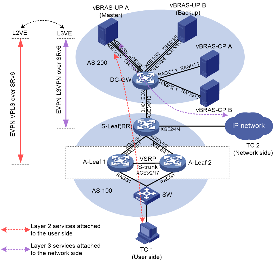
A-Leaf 1 and A-Leaf 2 are SR8800-X routers, the S-Leaf is a CR19000 core router, and the DC-GW is an S12500R switching router. Each vBRAS-UP is connected the DC-GW with four physical links. Due to the high density of connected interfaces, only two physical links are marked in the diagram for each vBRAS-UP.
Table 5 Interface IP plan
|
Device name |
Interface name |
IP address |
|
vBRAS-CP A |
LoopBack1 |
61.61.1.1/32 |
|
Route-Aggregation1.2 |
11.2.0.2/24 |
|
|
vBRAS-CP B |
LoopBack1 |
78.78.1.1/32 |
|
Route-Aggregation1.2 |
12.2.0.2/24 |
|
|
vBRAS-UP A |
LoopBack1 |
1.88.10.1/32 |
|
LoopBack2 |
1.88.10.100/32 1:88:10:100/128 |
|
|
XGE5/3/0.1 |
125.53.0.2/24 1250::2/64 |
|
|
XGE5/3/0.2 |
125.53.10.2/24 |
|
|
XGE5/4/0.1 |
125.54.0.2/24 1251::2/64 |
|
|
XGE5/4/0.2 |
125.54.10.2/24 |
|
|
XGE6/3/0.1 |
125.63.0.2/24 1252::2/64 |
|
|
XGE6/3/0.2 |
125.63.10.2/24 |
|
|
XGE6/4/0.1 |
125.64.0.2/24 1253::2/64 |
|
|
XGE6/4/0.2 |
125.64.10.2/24 |
|
|
vBRAS-UP B |
LoopBack1 |
1.88.11.1/32 |
|
LoopBack2 |
1.88.11.100/32 1:88:11::100/128 |
|
|
XGE5/3/0.1 |
126.53.0.2/24 1260::2/64 |
|
|
XGE5/3/0.2 |
126.53.10.2/24 |
|
|
XGE5/4/0.1 |
126.54.0.2/24 1261::2/64 |
|
|
XGE5/4/0.2 |
126.54.10.2/24 |
|
|
XGE6/3/0.1 |
126.63.0.2/24 1262::2/64 |
|
|
XGE6/3/0.2 |
126.63.10.2/24 |
|
|
XGE6/4/0.1 |
126.64.0.2/24 1263::2/64 |
|
|
XGE6/4/0.2 |
126.64.10.2/24 |
|
|
DC-GW |
LoopBack1 |
11.11.100.100/32 |
|
Route-Aggregation1.1 |
11.2.0.1/24 |
|
|
Route-Aggregation2.1 |
12.2.0.1/24 |
|
|
XGE1/0/1.1 |
125.53.0.1/24 1250::1/64 |
|
|
XGE1/0/1.2 |
125.53.10.1/24 |
|
|
XGE1/0/2.1 |
126.53.0.1/24 1260::1/64 |
|
|
XGE1/0/2.2 |
126.53.10.1/24 |
|
|
XGE1/0/3.1 |
125.54.0.1/24 1251::1/64 |
|
|
XGE1/0/3.2 |
125.54.10.1/24 |
|
|
XGE1/0/4.1 |
126.54.0.1/24 1261::1/64 |
|
|
XGE1/0/4.2 |
126.54.10.1/24 |
|
|
XGE1/0/5.1 |
125.63.0.1/24 1252::1/64 |
|
|
XGE1/0/5.2 |
125.63.10.1/24 |
|
|
XGE1/0/6.1 |
126.63.0.1/24 1262::1/64 |
|
|
XGE1/0/6.2 |
126.63.10.1/24 |
|
|
XGE1/0/7.1 |
125.64.0.1/24 1253::1/64 |
|
|
XGE1/0/7.2 |
125.64.10.1/24 |
|
|
XGE1/0/8.1 |
126.64.0.1/24 1263::1/64 |
|
|
XGE1/0/8.2 |
126.64.10.1/24 |
|
|
XGE1/0/10 |
709:1025::2/64 |
|
|
S-Leaf(RR) |
XGE3/0/10 |
709:1025::1/64 |
|
XGE3/0/1 |
3214::2/64 |
|
|
XGE3/0/2 |
3215::2/64 |
|
|
LoopBack1 |
17:14::1/128 |
|
|
XGE2/4/4.1 |
8.41.0.1/24 |
|
|
A-Leaf 1 |
XGE2/0/1 |
3214::1/64 |
|
XGE3/2/17 |
32.17.0.2/24 |
|
|
LoopBack1 |
8804::1/128 |
|
|
A-Leaf 2 |
XGE2/0/1 |
3215::1/64 |
|
XGE3/2/17 |
32.17.0.1/24 |
|
|
LoopBack1 |
8805::1/128 |
Analysis
· vBRAS-UP A and vBRAS-UP B each consist of four VMs. Two VMs act as MPU-VMs in primary and backup mode, and the other two VMs operate in standalone mode. Each VM has two logical interfaces for internal communication. Each MPU has one OM management port for communication with MANO and network management platforms. Each LPU has two external interfaces that forward traffic of all services except for management services.
· The vBRAS-CPs, the vBRAS-UPs, and the DC-GW are in one AS. The S-Leaf and the two A-Leafs are in another AS. The DC-GW and the S-Leaf act as ASBRs, and they have an EBGP peer session. With this session, the two ASs can import IGP routes from each other and advertise information (such as interconnect addresses and SRv6 locators) to each other, achieving inter-AS communication.
· Each distributed vBRAS-UP is connected to the DC-GW through four subinterfaces. ECMP routes are used to distribute uplink and downlink traffic across those subinterfaces. OSPFv3 routes traffic between the directly connected interfaces of the vBRAS-UP and the DC-GW.
· The S-Leaf and the two A-Leafs use OSPFv3 for communication.
· In this example, the S-Leaf also acts as a route reflector (RR), reflecting BGP EVPN routes between the vBRAS-UP side and the A-Leaf side.
· VSRP and S-Trunk are deployed on the two A-Leafs to ensure service reliability.
· The two A-Leafs are added to a VSRP group to synchronize ARP data. They also form an S-trunk system and each of them is configured with aggregate subinterfaces that provide access services for users.
· Both L2VE and L3VE interfaces are created on each distributed vBRAS-UP. The L2VE interfaces are used to terminate Layer 2 services through and steer them to L3VE interfaces. The L3VE interfaces are managed by vBRAS-CPs. Users can connect to either L3VE interfaces or L3VE subinterfaces for network access. In this example, users are connected to L3VE interfaces.
· Users come online from L3VE interfaces through EVPN VPLS over SRv6. A physical subinterface of the S-Leaf is configured as the gateway of the network side. The network is attached to the distributed vBRAS-UPs through EVPN L3VPN over SRv6.
Restrictions and guidelines
This example focuses on configuring EVPN VPLS over SRv6 and EVPN L3VPN over Srv6 for vBRAS-UPs.
|
No. |
Description |
Configuration example |
|
1 |
On the CAS platform, set a MTU value greater than 3500 for the related interfaces of VMs. As a best practice, set the MTU value to 9000. |
|
|
2 |
If the vBRAS-UPs use a user-defined load balancing group, you must add their LPUs to the group to ensure correct traffic forwarding. However, adding an LPU to the group will clear all configurations on the external interfaces of that LPU. Therefore, the configuration order should be: 1. Create a user-defined load balancing group. 2. Add the related LPUs to the group. 3. Configure the external interfaces. |
|
|
3 |
After adding the related LPUs to the user-defined load balancing group, you must bind the L3VE interfaces to that load balancing group. |
|
|
3 |
The IGPs supported by vBRAS-UPs only include OSPF and OSPFv3. OSPF uses the links of those vBRAS-UPs for route calculation only after the vBRAS-UPs finish startup. |
|
|
4 |
When multiple VSIs are deployed, each VSI must be bound to a unique L2VE interface. An L2VE interface can have only one VSI binding. |
|
|
5 |
In live networks, distributed vBRAS-UPs only use the ECMP method for traffic forwarding, not the link aggregation method. |
|
|
6 |
On the vBRAS-UPs, subinterfaces of logical interfaces (such as VE-L3VPN interfaces) only support common VLAN termination (vlan-type) and do not support user VLAN termination (user-vlan). |
|
|
7 |
On an A-Leaf, if the access mode of an AC port is VLAN, it only supports exact VLAN match, not fuzzy match. |
|
|
8 |
Set the mask length for the ODAP subnet as small as possible. |
|
|
9 |
On the A-Leaf devices, VSIs should not use the default broadcast suppression settings, because these settings lead to low performance in terms of users coming online. As a best practice, make sure the bandwidth threshold that triggers broadcast suppression is greater than 6000. |
|
|
10 |
On the vBRAS-UPs, disable online-user detection on all user-facing L3VE interfaces as a best practice. If online-user detection is required, the recommended detection interval is 7200 (1200*6). |
As a best practice, disable online-user detection on all user-facing L3VE interfaces as follows: If online-user detection is required, enable this feature as follows: |
|
11 |
Distributed vBRAS-UPs only support the SRv6 BE scenario. TE is not involved. |
|
|
12 |
Configure the substitute-as feature on the S-Leaf. |
This feature is mainly applicable to dual-DC scenarios. Traffic can be routed between two DCs with the same AS number, traversing the carrier network. |
|
13 |
Configure the SoO feature on the S-Leaf. |
When two DC-GWs are deployed within a DC, use the SoO feature to prevent loops. |
Prerequisites
Before configuring network functions on devices (including vBRAS-CPs and vBRAS-UPs), deploy distributed vBRAS-UPs.
Software environment
Before deploying distributed vBRAS-UPs (also called vUPs), ensure that the related vBRAS-CPs and software platforms are deployed. These software platforms include H3C UIS, CAS, CloudOS, VNF Manager, and VNFM-vBRAS.
|
|
NOTE: After installing CAS, you can deploy CAS-CVMs (also called CVM) or CAS-CVK (also called CVK). In this document, CVMs and CVKs are deployed as follows: · CVMs are deployed in the UIS cluster as VMs. They are used for CVK management, acting as virtualization management systems. · CVKs are deployed on servers. They host various VMs for vBRAS, acting as virtualization kernel platforms. |
Hardware environment
To deploy a minimal distributed vUP system consisting of two MPU-VMs and two LPU-VMs, prepare 2 CVK servers for the deployment. Each CVK server must be deployed with one MPU-VM and one LPU-VM. A CVK server refers to a server that is already installed with the CVK software or is waiting for CVK software installment.
To ensure that VMs in the distributed vUP and the CVK software can have sufficient hardware resources, the minimum hardware requirements for a single CVK server are as follows:
· CPU: 2 * 12 cores
· Memory: 256 GB. Each VM uses 64 GB, and part of the memory must be reserved for the CVK software.
· NIC: 3 * 4-port 10-GE NICs with fiber interfaces. For more information about the NIC and interface plan, see Figure 42.
Figure 42 NIC and interface plan
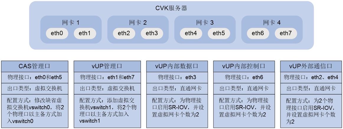
|
|
NOTE: · SR-IOV requires support from physical NICs. Currently, only Intel 82599ES and Intel X710 support configuring SR-IOV. · The number of vNICs refers to the number of virtual NICs into which the physical NICs are virtualized. If the related BIOS or NIC is using an outdated firmware version, the number of vNICs might be -1. In this situation, you cannot change the number of vNICs. |
Basic configuration
Before deploying the distributed vUPs, perform the following tasks:
· On the two CVK servers:
¡ Access the BIOS page, disable the hyper-threading feature, and then enable the high performance mode on the power management module.
¡ Install the related CAS image and select Cloud Virtualization Kernel (CVK) as the base environment.
· On the CAS platform, configure CVMs to manage CVKs.
· Interoperate CloudOS with CAS.
|
|
NOTE: · For more information about BIOS, see the BIOS user guide for the related server model. · For more information about CAS image installation and CAS, see the installation guide for the related version of H3C CAS Installation Guide. · For more information about CloudOS, see the related version of H3C CloudOS Deployment Guide. |
Configure the boot configuration of CVK hosts
Configure the startup items for the two CVK hosts separately (IOMMU and CPU isolation) as follows:
1. Log in to CAS, select Resources from the left navigation pane, select the CVK host used for distributed-vUP deployment, click Advanced > Boot Configuration, and then enable IOMMU and CPU isolation.
|
|
NOTE: The CAS login method depends on the version. For example, in E0710P09, you can access the login page by entering http://IP address:8080/cas in the address bar of the browser. The IP address argument represents is the hot standby VIP of the CVM nodes. |
2. Click the ![]() icon in the Actions column for a NUMA
node and select the CPUs to be isolated, ensuring that each NUMA node has a
minimum of one CPU that is not isolated.
icon in the Actions column for a NUMA
node and select the CPUs to be isolated, ensuring that each NUMA node has a
minimum of one CPU that is not isolated.
3. Click OK, and then click Save to complete the boot configuration.
4. After modifying the IOMMU configuration, restart the CVK host to have the modification take effect. To prevent the restart from affecting existing VMs, restart the CVK host in maintenance mode as a best practice.
Configure vSwitches for CVK hosts
Configure vSwitches for the two CVK hosts separately as follows:
1. Log in to CAS, select Resources from the left navigation pane, select the CVK host used for distributed-vUP deployment, and then click the vSwitches tab.
2. Use the default vSwitch (vswitch0) as the CAS management port and select the related physical NIC for it.
3. Create a new virtual switch, vswitch1, to act as the vUP management port and select the related physical NIC for it.
Configure physical NICs for CVK hosts
Configure physical NICs for the two CVK hosts separately as follows:
· For all pass-through NICs, enable SR-IOV and set the number of vNICs to 2.
· For pass-through NICs corresponding to the vUP internal control ports and data ports, set the MTU value to 9000.
1. Log in to CAS, select Resources from the left navigation pane, select the CVK host used for distributed-vUP deployment, and then click the Physical NICs tab.
2. Select each physical interface corresponding to a pass-through NIC, enable SR-IOV, and set the number of vNICs to 2.
3. Select each physical interface corresponding to a vUP internal control or data port, and then change the MTU value to 9000.
Add CloudOS clusters as cloud platforms on VNFM-vBRAS
Log in to VNFM-vBRAS, navigate to the cloud platform page, click Add to add a CloudOS cluster by its management-network VIP.
Edit the configuration file
Contact H3C Technical Support to obtain the installation package (including a zipped VNF package and an ISO image file), and modify the yml file in the VNF package according to the actual network condition.
After decompression, the VNF package includes:
· Folder Definitions: Contains two files, nodes.yml and vbras.yml.
· Folder TOSCA-Metadata: Contains the TOSCA.meta file.
· csar.meta file
You must modify the attributes in the vbras.yml file based on the actual networking conditions. This file is located in the Definitions folder of the VNF package.
1. Decompress the VNF package for distributed vUPs, open the Definitions folder, and then double click the vbras.yml file. This file describes MPU_VM and LPU-VM information. The key information is as shown in Table 6.
|
Object |
Attribute |
Description |
|
init |
control_network_vlan |
Control VLAN. Modify this attribute based on the actual networking conditions, and ensure that all control links on VMs are configured with the same control VLAN. |
|
data_network_vlan |
Data VLAN. Modify this attribute based on the actual networking conditions. |
|
|
control_network_segment |
Control network. Modify this attribute based on the actual networking conditions, and ensure that all control links on VMs are in the same control network. |
|
|
data_network_segment |
Data network. Modify this attribute based on the actual networking conditions. |
|
|
om_default_vpn |
Default VPN for the vUP management port. Modify this attribute based on the actual networking conditions. |
|
|
mpuvm_count |
Number of MPU-VMs. The default value is 2. As a best practice, use the default value. |
|
|
lpuvm_count |
Number of LPU-VMs. The default value is 2. As a best practice, use the default value. |
|
|
mpuvm_slot_id |
Slot numbers of the MPU-VMs, which corresponds to the number of MPU-VMs. The default value range is 1 to 2. As a best practice, use the default value range. |
|
|
lpuvm_slot_id |
Slot numbers of the LPU-VMs, which corresponds to the number of LPU-VMs. The default value range is 5 to 6. As a best practice, use the default value range. |
|
|
MPU_VM and LPU-VM |
cpu_num |
Number of CPU cores. The recommended value is 11. |
|
memory |
Memory size. The recommended value is 65536. |
|
|
storage |
Storage capacity. The recommended value is 32768. |
|
|
vm_port_name |
Interface name, which is not editable. |
|
|
vm_port_type |
Interface type, which is not editable. Supported interface types include: · om: vUP management port. · inner-ctrl: Internal control port on the vUP. · inner-data: Internal data port on the vUP. · external: External communication port on the vUP. |
|
|
logical_nic_name |
Logic NIC name, which corresponds to the classic network name during the interoperation between CloudOS and CAS. Modify this attribute based on the actual networking conditions. |
2. Modify the configuration information in the vbras.yml file according to the actual networking conditions. After confirming that the new configuration is correct, save it. In this example, the modified configuration (in gray) is as follows:
...
node_templates:
init:
type: toscale-group.nodes.vbrasso.init
properties:
ctrlvm_ip: {get_input: ctrlvm_ip}
login_user: {get_input: login_user}
login_password: {get_input: login_password}
mask: {get_input: mask}
control_network_vlan: 281
data_network_vlan: 282
control_network_segment: 2.81.0.0/24
data_network_segment: 2.82.0.0/24
om_default_vpn: mge
mpuvm_count: 2
lpuvm_count: 2
mpuvm_slot_id: 1-2
lpuvm_slot_id: 5-6
MPU_VM:
type: tosca.nodes.vbrasso.vm
properties:
cpu_num: 11
memory: 65536
storage: 32768
network_binding:
- vm_port_name: Interface2/0
vm_port_type: inner-ctrl
logical_nic_name: SRIOV-vUPeth2
start_ip: ''
end_ip: ''
mask: ''
- vm_port_name: Interface3/0
vm_port_type: inner-data
logical_nic_name: SRIOV-vUPeth3
start_ip: ''
end_ip: ''
mask: ''
- vm_port_name: Interface1/0
vm_port_type: om
logical_nic_name: vUPvswitch0
start_ip: ''
end_ip: ''
mask: ''
LPU_VM:
type: tosca.nodes.vbrasso.vm
properties:
cpu_num: 11
memory: 65536
storage: 32768
network_binding:
- vm_port_name: Interface1/0
vm_port_type: inner-ctrl
logical_nic_name: SRIOV-vUPeth2
start_ip: ''
end_ip: ''
mask: ''
- vm_port_name: Interface2/0
vm_port_type: inner-data
logical_nic_name: SRIOV-vUPeth3
start_ip: ''
end_ip: ''
mask: ''
- vm_port_name: Interface3/0
vm_port_type: external
logical_nic_name: SRIOV-vUPeth4
start_ip: ''
end_ip: ''
mask: ''
- vm_port_name: Interface4/0
vm_port_type: external
logical_nic_name: SRIOV-vUPeth5
start_ip: ''
end_ip: ''
mask: ''
3. Return to the parent folder, select all contents of the VNF package (including the Definitions folder, the TOSCA-Metadata folder, and the csar.meta file), and zip them as a package.
|
|
CAUTION: To avoid VNF package resolution failure during deployment, make sure: · All contents of the VNF package are selected and the parent folder is not selected. · The VNF package is in .zip format. |
Deploy distributed vUP VMs (including MPU-VMs and LPU-VMs) through VNFM-vBRAS
On the VNFM-vBRAS page, navigate to the Deployment > Deployment page, and then follow the deployment wizard to complete the following operations:
1. In the VNF Package step, click Upload, select and upload the desired VNF package, and then click Next.
2. In the Mirroring step, click Upload, select and upload the desired image file of distributed vUPs, and then click Next.
3. In the Cloud Platform step, select the cloud platform added in Add CloudOS clusters as cloud platforms on VNFM-vBRAS, and select the AZ created during the configuration of Cloud OS interoperability with CAS. Click Next.
4. In the Deployment Parameters step, enter the vBRAS name, username, and password as needed, and fill in the management IP and subnet mask based on the network plan (used to manage and access distributed vUPs).
5. Click Finish. In the pop-up dialog box, verify that the configuration is correct, and then click Apply to start the initial deployment. The system will complete the deployment after a while.
Verify that the VM configurations on CAS CVM
1. After the deployment, CAS CVM displays the VMs created on the two CVK hosts. Each CVK host has one MPU-VM and one LPU-VM.
2. From the left navigation pane, select a new VM in the Resources menu, click Edit, and then identify whether the following settings are correct:
¡ Bindings of physical CPUs and vCPUs. The bound physical CPUs must be consistent with the CPUs selected during CPU isolation configuration in “Configure the boot configuration of CVK hosts”.
¡ VLAN ID for the Intel 82599ES NIC. The VLAN ID should be 4095.
¡ Enabling status of virtual NUMA. Make sure this feature is enabled.
Procedures
Configuring vBRAS-CP A
# Create VPN-instance cusp, which maintains IP addresses of various channels in its routing table.
[CPA] ip vpn-instance cusp
[CPA-vpn-instance-cusp] quit
# Assign an IP address to the Lookback1 interface of vBRAS-CP A.
[CPA] interface LoopBack1
[CPA-LoopBack1] ip binding vpn-instance cusp
[CPA-LoopBack1] ip address 61.61.1.1 255.255.255.255
[CPA-LoopBack1] quit
# Configure aggregate interface Route-Aggregation1, which connects vBRAS-CP A with the DC-GW.
[CPA] interface Route-Aggregation1
[CPA-Route-Aggregation1] link-aggregation mode dynamic
[CPA-Route-Aggregation1] quit
[CPA] interface Route-Aggregation1.2
[CPA-Route-Aggregation1.2] ip binding vpn-instance cusp
[CPA-Route-Aggregation1.2] ip address 11.2.0.2 255.255.255.0
[CPA-Route-Aggregation1.2] vlan-type dot1q vid 1102
[CPA-Route-Aggregation1.2] quit
# Configure the member interfaces of aggregate interface Route-Aggregation1.
[CPA] interface GigabitEthernet5/3/0
[CPA-GigabitEthernet5/3/0] port link-aggregation group 1
[CPA-GigabitEthernet5/3/0] quit
[CPA] interface GigabitEthernet5/4/0
[CPA-GigabitEthernet5/4/0] port link-aggregation group 1
[CPA-GigabitEthernet5/4/0] quit
# Establish management control, and protocol channels between vBRAS-CP A and vBRAS-UP A, and create a remote interface to manage the L3VE interface on vBRAS-UP A.
[CPA] netconf-client
[CPA-netconf-client] source-address 61.61.1.1
[CPA-netconf-client] connection 10
[CPA-netconf-client-connection-10] user-name netconf password simple 123456TESTplat&!
[CPA-netconf-client-connection-10] destination-address 1.88.10.1 vpn-instance cusp
[CPA-netconf-client-connection-10] quit
[CPA-netconf-client] quit
[CPA] cusp controller
[CPA-cusp-controller] listening-ip 61.61.1.1
[CPA-cusp-controller] agent up10
[CPA-cusp-controller-agent-up10] agent-ip 1.88.10.1
[CPA-cusp-controller-agent-up10] quit
[CPA-cusp-controller] quit
[CPA] up-manage id 1040
[CPA-up-manage-1040] bind netconf-connection 10
[CPA-up-manage-1040] control-tunnel cusp-agent up10
[CPA-up-manage-1040] protocol-tunnel vxlan 110 source 61.61.1.1 destination 1.88.10.1 vpn-instance cusp
[CPA-up-manage-1040] remote interface VE-L3VPN13
[CPA-up-manage-1040] up-config
[CPA-up-manage-1040-up-config] cusp agent up10
[CPA-up-manage-1040-up-config-cusp-agent-up10] local-address 1.88.10.1 vpn-instance cusp
[CPA-up-manage-1040-up-config-cusp-agent-up10] bfd enable template BFD_CUSP
[CPA-up-manage-1040-up-config-cusp-agent-up10] controller address 61.61.1.1
[CPA-up-manage-1040-up-config-cusp-agent-up10] quit
[CPA-up-manage-1040-up-config] cu-agent
[CPA-up-manage-1040-up-config-cu-agent] protocol-tunnel vxlan 110 source 1.88.10.1 destination 61.61.1.1 vpn-instance cusp
[CPA-up-manage-1040-up-config-cu-agent] quit
[CPA-up-manage-1040-up-config] quit
[CPA-up-manage-1040] quit
# Establish management, control, and protocol channels between vBRAS-CP A and vBRAS-UP B, and create a remote interface to manage the L3VE interface on vBRAS-UP B.
[CPA] netconf-client
[CPA-netconf-client] source-address 61.61.1.1
[CPA-netconf-client] connection 11
[CPA-netconf-client-connection-11] user-name netconf password simple 123456TESTplat&!
[CPA-netconf-client-connection-11] destination-address 1.88.11.1 vpn-instance cusp
[CPA-netconf-client-connection-11] quit
[CPA-netconf-client] quit
[CPA] cusp controller
[CPA-cusp-controller] listening-ip 61.61.1.1
[CPA-cusp-controller] agent up11
[CPA-cusp-controller-agent-up11] agent-ip 1.88.11.1
[CPA-cusp-controller-agent-up11] quit
[CPA-cusp-controller] quit
[CPA] up-manage id 1044
[CPA-up-manage-1044] bind netconf-connection 11
[CPA-up-manage-1044] control-tunnel cusp-agent up11
[CPA-up-manage-1044] protocol-tunnel vxlan 111 source 61.61.1.1 destination 1.88.11.1 vpn-instance cusp
[CPA-up-manage-1044] remote interface VE-L3VPN13
[CPA-up-manage-1044] up-config
[CPA-up-manage-1044-up-config] cusp agent up11
[CPA-up-manage-1044-up-config-agent-up11] local-address 1.88.11.1 vpn-instance cusp
[CPA-up-manage-1044-up-config-agent-up11] bfd enable template BFD_CUSP
[CPA-up-manage-1044-up-config-agent-up11] controller address 61.61.1.1
[CPA-up-manage-1044-up-config-agent-up11] quit
[CPA-up-manage-1044-up-config] cu-agent
[CPA-up-manage-1044-up-config-cu-agent] protocol-tunnel vxlan 111 source 1.88.11.1 destination 61.61.1.1 vpn-instance cusp
[CPA-up-manage-1044-up-config-cu-agent] quit
[CPA-up-manage-1044-up-config] quit
[CPA-up-manage-1044] quit
# Create BFD template BFD_CUSP, which enables BFD-based fast fault detection for CUSP connections.
[CPA] bfd template BFD_CUSP
[CPA-bfd-template-BFD_CUSP] bfd min-transmit-interval 200
[CPA-bfd-template-BFD_CUSP] bfd min-receive-interval 200
[CPA-bfd-template-BFD_CUSP] bfd detect-multiplier 10
[CPA-bfd-template-BFD_CUSP] quit
# Create a CPDR group.
[CPA] cp disaster-recovery group 2 id 2
[CPA-cpdr-group-2] set role master
[CPA-cpdr-group-2] up-id 1040 1044
[CPA-cpdr-group-2] switchover auto enable
[CPA-cpdr-group-2] quit
# Configure the 1:1 hot standby mode for vBRAS-CP A.
[CPA] up-backup-group 2
[CPA-up-backup-group-2] backup up-id 1040
[CPA-up-backup-group-2] backup up-id 1044
[CPA-up-backup-group-2] quit
[CPA] up-backup-profile 3 hot-standby
[CPA-up-backup-profile-3] undo failure-recovery-switch enable
[CPA-up-backup-profile-3] backup route-advertise
[CPA-up-backup-profile-3] up-id 1040 network-state track uplink-group 1
[CPA-up-backup-profile-3] up-id 1044 network-state track uplink-group 2
[CPA-up-backup-profile-3] control-tunnel-up switchover msec-delay 60000
[CPA-up-backup-profile-3] control-tunnel-down switchover delay 5
[CPA-up-backup-profile-3] backup-group master Remote-L3VE1040/1 backup Remote-L3VE1044/1 vrid 102 resource-id 1
[CPA-up-backup-profile-3] quit
# Create a VPN instance for ITMS services.
[CPA] ip vpn-instance itms
[CPA-vpn-ipv4-itms] quit
# Configure an IP address pool on vBRAS-CP A.
[CPA] ip pool itms odap
[CPA-ip-pool-itms] vpn-instance itms
[CPA-ip-pool-itms] network 175.59.0.0 mask 255.255.0.0
[CPA-ip-pool-itms] subnet mask-length 20
[CPA-ip-pool-itms] subnet alloc-mode interface
[CPA-ip-pool-itms] subnet utilization mark high 90 low 50
[CPA-ip-pool-itms] dns-list 172.30.2.1 172.41.255.1
[CPA-ip-pool-itms] ip-in-use threshold 90
[CPA-ip-pool-itms] network 175.94.0.0 mask 255.255.0.0 secondary
[CPA-ip-pool-itms-secondary] quit
[CPA-ip-pool-itms] network 175.95.0.0 mask 255.255.0.0 secondary
[CPA-ip-pool-itms-secondary] quit
[CPA-ip-pool-itms] network 175.96.0.0 mask 255.255.0.0 secondary
[CPA-ip-pool-itms-secondary] quit
[CPA-ip-pool-itms] quit
# Create an ISP domain for ITMS services and enter its view to configure user authorization and accounting settings.
[CPA] domain name itms
[CPA-isp-itms] authorization-attribute ip-pool itms
[CPA-isp-itms] authorization-attribute vpn-instance itms
[CPA-isp-itms] authentication ipoe none
[CPA-isp-itms] authorization ipoe none
[CPA-isp-itms] accounting ipoe none
[CPA-isp-itms] quit
# Configure the master and backup interfaces in hot standby mode. These interfaces provide access services for IPoE users.
[CPA] interface Remote-L3VE1040/1.1
[CPA-Remote-L3VE1040/1.1] vlan-type dot1q vid 319 second-dot1q 100
[CPA-Remote-L3VE1040/1.1] ip subscriber initiator arp enable
[CPA-Remote-L3VE1040/1.1] ip subscriber l2-connected enable
[CPA-Remote-L3VE1040/1.1] ip subscriber dhcp domain itms
[CPA-Remote-L3VE1040/1.1] ip subscriber initiator unclassified-ip enable matching-user
[CPA-Remote-L3VE1040/1.1] undo ip subscriber user-detect
[CPA-Remote-L3VE1040/1.1] quit
[CPA] interface Remote-L3VE1044/1.1
[CPA-Remote-L3VE1044/1.1] vlan-type dot1q vid 319 second-dot1q 100
[CPA-Remote-L3VE1044/1.1] ip subscriber initiator arp enable
[CPA-Remote-L3VE1044/1.1] ip subscriber l2-connected enable
[CPA-Remote-L3VE1044/1.1] ip subscriber dhcp domain itms
[CPA-Remote-L3VE1044/1.1] ip subscriber initiator unclassified-ip enable matching-user
[CPA-Remote-L3VE1044/1.1] undo ip subscriber user-detect
[CPA-Remote-L3VE1044/1.1] quit
Configuring vBRAS-CP B
# Create VPN-instance cusp, which maintains protocol channel address information in its routing table.
[CPB] ip vpn-instance cusp
[CPB-vpn-instance-cusp] quit
# Assign an IP address to the Lookback1 interface of vBRAS-CP B.
[CPB] interface LoopBack1
[CPB-LoopBack1] ip binding vpn-instance cusp
[CPB-LoopBack1] ip address 78.78.1.1 255.255.255.255
[CPB-LoopBack1] quit
# Configure aggregate interface Route-Aggregation1, which connects vBRAS-CP B with the DC-GW.
[CPB] interface Route-Aggregation1
[CPB-Route-Aggregation1] link-aggregation mode dynamic
[CPB-Route-Aggregation1] quit
[CPB] interface Route-Aggregation1.2
[CPB-Route-Aggregation1.2] ip binding vpn-instance cusp
[CPB-Route-Aggregation1.2] ip address 12.2.0.2 255.255.255.0
[CPB-Route-Aggregation1.2] vlan-type dot1q vid 1202
[CPB-Route-Aggregation1.2] quit
# Configure the member interfaces of aggregate interface Route-Aggregation1.
[CPB] interface GigabitEthernet5/3/0
[CPB-GigabitEthernet5/3/0] port link-aggregation group 1
[CPB] interface GigabitEthernet5/4/0
[CPB-GigabitEthernet5/4/0] port link-aggregation group 1
# Establish management, control, and protocol channels between vBRAS-CP B and vBRAS-UP A, and create a remote interface to manage the L3VE interface on vBRAS-UP A.
[CPB] netconf-client
[CPB-netconf-client] source-address 78.78.1.1
[CPB-netconf-client] connection 10
[CPB-netconf-client-connection-10] user-name netconf password simple 123456TESTplat&!
[CPB-netconf-client-connection-10] destination-address 1.88.10.1 vpn-instance cusp
[CPB-netconf-client-connection-10] quit
[CPB-netconf-client] quit
[CPB] cusp controller
[CPB-cusp-controller] listening-ip 78.78.1.1
[CPB-cusp-controller] agent up10
[CPB-cusp-controller-agent-up10] agent-ip 1.88.10.1
[CPB-cusp-controller-agent-up10] quit
[CPB-cusp-controller] quit
[CPB] up-manage id 1040
[CPB-up-manage-1040] bind netconf-connection 10
[CPB-up-manage-1040] control-tunnel cusp-agent up10
[CPB-up-manage-1040] protocol-tunnel vxlan 210 source 78.78.1.1 destination 1.88.10.1 vpn-instance cusp
[CPB-up-manage-1040] remote interface VE-L3VPN13
[CPB-up-manage-1040] up-config
[CPB-up-manage-1040-up-config] cusp agent up10
[CPB-up-manage-1040-up-config-cusp-agent-up10] local-address 1.88.10.1 vpn-instance cusp
[CPB-up-manage-1040-up-config-cusp-agent-up10] bfd enable template BFD_CUSP
[CPB-up-manage-1040-up-config-cusp-agent-up10] controller address 78.78.1.1
[CPB-up-manage-1040-up-config-cusp-agent-up10] quit
[CPB-up-manage-1040-up-config] cu-agent
[CPB-up-manage-1040-up-config-cu-agent] protocol-tunnel vxlan 210 source 1.88.10.1 destination 78.78.1.1 vpn-instance cusp
[CPB-up-manage-1040-up-config-cu-agent] quit
[CPB-up-manage-1040-up-config] quit
[CPB-up-manage-1040] quit
# Establish management, control, and protocol channels between vBRAS-CP B and vBRAS-UP B, and create a remote interface to manage the L3VE interface on vBRAS-UP B.
[CPB] netconf-client
[CPB-netconf-client] source-address 78.78.1.1
[CPB-netconf-client] connection 11
[CPB-netconf-client-connection-11] user-name netconf password simple 123456TESTplat&!
[CPB-netconf-client-connection-11] destination-address 1.88.11.1 vpn-instance cusp
[CPB-netconf-client-connection-11] quit
[CPB-netconf-client] quit
[CPB] cusp controller
[CPB-cusp-controller] listening-ip 78.78.1.1
[CPB-cusp-controller] agent up11
[CPB-cusp-controller-agent-up11] agent-ip 1.88.10.1
[CPB-cusp-controller-agent-up11] quit
[CPB-cusp-controller] quit
[CPB] up-manage id 1044
[CPB-up-manage-1044] bind netconf-connection 11
[CPB-up-manage-1044] control-tunnel cusp-agent up11
[CPB-up-manage-1044] protocol-tunnel vxlan 211 source 78.78.1.1 destination 1.88.11.1 vpn-instance cusp
[CPB-up-manage-1044] remote interface VE-L3VPN13
[CPB-up-manage-1044] up-config
[CPB-up-manage-1044-up-config] cusp agent up11
[CPB-up-manage-1044-up-config-agent-up11] local-address 1.88.11.1 vpn-instance cusp
[CPB-up-manage-1044-up-config-agent-up11] bfd enable template BFD_CUSP
[CPB-up-manage-1044-up-config-agent-up11] controller address 78.78.1.1
[CPB-up-manage-1044-up-config-agent-up11] quit
[CPB-up-manage-1044-up-config] cu-agent
[CPB-up-manage-1044-up-config-cu-agent] protocol-tunnel vxlan 211 source 1.88.11.1 destination 78.78.1.1 vpn-instance cusp
[CPB-up-manage-1044-up-config-cu-agent] quit
[CPB-up-manage-1044-up-config] quit
[CPB-up-manage-1044] quit
# Create BFD template BFD_CUSP, which enables BFD-based fast fault detection for CUSP connections.
[CPB] bfd template BFD_CUSP
[CPB-bfd-template-BFD_CUSP] bfd min-transmit-interval 200
[CPB-bfd-template-BFD_CUSP] bfd min-receive-interval 200
[CPB-bfd-template-BFD_CUSP] bfd detect-multiplier 10
[CPB-bfd-template-BFD_CUSP] quit
# Create a CPDR group.
[CPB] cp disaster-recovery group 2 id 2
[CPB-cpdr-group-2] set role backup
[CPB-cpdr-group-2] up-id 1040 1044
[CPB-cpdr-group-2] switchover auto enable
[CPB-cpdr-group-2] quit
# Configure the 1:1 hot standby mode for vBRAS-CP B.
[CPB] up-backup-group 2
[CPB-up-backup-group-2] backup up-id 1040
[CPB-up-backup-group-2] backup up-id 1044
[CPB-up-backup-group-2] quit
[CPB] up-backup-profile 3 hot-standby
[CPB-up-backup-profile-3] undo failure-recovery-switch enable
[CPB-up-backup-profile-3] backup route-advertise
[CPB-up-backup-profile-3] up-id 1040 network-state track uplink-group 1
[CPB-up-backup-profile-3] up-id 1044 network-state track uplink-group 2
[CPB-up-backup-profile-3] control-tunnel-up switchover msec-delay 60000
[CPB-up-backup-profile-3] control-tunnel-down switchover delay 5
[CPB-up-backup-profile-3] backup-group master Remote-L3VE1040/1 backup Remote-L3VE1044/1 vrid 102 resource-id 1
[CPB-up-backup-profile-3] quit
# Create a VPN instance for ITMS services.
[CPB] ip vpn-instance itms
[CPB-vpn-ipv6-itms] quit
# Configure an IP address pool on vBRAS-CP B.
[CPB] ip pool itms odap
[CPB-ip-pool-itms] vpn-instance itms
[CPB-ip-pool-itms] network 175.59.0.0 mask 255.255.0.0
[CPB-ip-pool-itms] subnet mask-length 20
[CPB-ip-pool-itms] subnet alloc-mode interface
[CPB-ip-pool-itms] subnet utilization mark high 90 low 50
[CPB-ip-pool-itms] dns-list 172.30.2.1 172.41.255.1
[CPB-ip-pool-itms] ip-in-use threshold 90
[CPB-ip-pool-itms] network 175.94.0.0 mask 255.255.0.0 secondary
[CPB-ip-pool-itms-secondary] quit
[CPB-ip-pool-itms] network 175.95.0.0 mask 255.255.0.0 secondary
[CPB-ip-pool-itms-secondary] quit
[CPB-ip-pool-itms] network 175.96.0.0 mask 255.255.0.0 secondary
[CPB-ip-pool-itms-secondary] quit
[CPB-ip-pool-itms] quit
# Create an ISP domain for ITMS services and enter its view to configure user authorization and accounting settings.
[CPB] domain name itms
[CPB-isp-itms] authorization-attribute ip-pool itms
[CPB-isp-itms] authorization-attribute vpn-instance itms
[CPB-isp-itms] authentication ipoe none
[CPB-isp-itms] authorization ipoe none
[CPB-isp-itms] accounting ipoe none
[CPB-isp-itms] quit
# Configure the master and backup interfaces in hot standby mode. These interfaces provide access services for IPoE users.
[CPB] interface Remote-L3VE1040/1.1
[CPB-Remote-L3VE1040/1.1] vlan-type dot1q vid 319 second-dot1q 100
[CPB-Remote-L3VE1040/1.1] ip subscriber initiator arp enable
[CPB-Remote-L3VE1040/1.1] ip subscriber l2-connected enable
[CPB-Remote-L3VE1040/1.1] ip subscriber dhcp domain itms
[CPB-Remote-L3VE1040/1.1] ip subscriber initiator unclassified-ip enable matching-user
[CPB-Remote-L3VE1040/1.1] undo ip subscriber user-detect
[CPB-Remote-L3VE1040/1.1] quit
[CPB] interface Remote-L3VE1044/1.1
[CPB-Remote-L3VE1044/1.1] vlan-type dot1q vid 319 second-dot1q 100
[CPB-Remote-L3VE1044/1.1] ip subscriber initiator arp enable
[CPB-Remote-L3VE1044/1.1] ip subscriber l2-connected enable
[CPB-Remote-L3VE1044/1.1] ip subscriber dhcp domain itms
[CPB-Remote-L3VE1044/1.1] ip subscriber initiator unclassified-ip enable matching-user
[CPB-Remote-L3VE1044/1.1] undo ip subscriber user-detect
[CPB-Remote-L3VE1044/1.1] quit
Configuring vBRAS-UP A
# Configure the device to operate in user plane mode.
<UPA> system-view
[UPA] work-mode user-plane
Configure the management channel (on NETCONF server)
# Enable the Stelnet server.
[UPA] ssh server enable
# Enable NETCONF over SSH.
[UPA] netconf ssh server enable
# Enable scheme authentication for user lines VTY 0 through VTY 63, through which the NETCONF over SSH clients log in.
[UPA] line vty 0 63
[UPA-line-vty0-63] authentication-mode scheme
[UPA-line-vty0-63] quit
# Add a device management user named admin and set the password to 123456TESTplat&! in plaintext form. Authorize the user to use the SSH service and assign the network-admin user role to the user.
[UPA] local-user admin class manage
[UPA-luser-manage-netconf] password simple 123456TESTplat&!
[UPA-luser-manage-netconf] service-type ssh
[UPA-luser-manage-netconf] authorization-attribute user-role network-admin
[UPA-luser-manage-netconf] quit
# Configure a BFD template. The parameter values are based on the actual network conditions. The BFD template must be configured on both the CPs and UPs.
[UPA] bfd template BFD_CUSP
[UPA-bfd-template-BFD_CUSP] bfd min-transmit-interval 200
[UPA-bfd-template-BFD_CUSP] bfd min-receive-interval 200
[UPA-bfd-template-BFD_CUSP] bfd detect-multiplier 10
[UPA-bfd-template-BFD_CUSP] quit
# Configure the server type as NETCONF and authentication mode as password authentication for SSH user admin.
[UPA] ssh user admin service-type netconf authentication-type password
# Create an auto scaling group and add LPU-VMs to it.
[UPA] scale-group name 1 id 1
[UPA-scale-group-1] route-tag 100
[UPA-scale-group-1] load-balance metric users
[UPA-scale-group-1] slot 5 to 6
[UPA-scale-group-1] quit
# Enable SRv6, and then configure an SRv6 locator and a source address for the outer IPv6 header of SRv6 VPN packets. The specified source address must be the IPv6 address of the local Loopback2 interface.
[UPA] segment-routing ipv6
[UPA-segment-routing-ipv6] encapsulation source-address 1:88:10::100
[UPA-segment-routing-ipv6] locator vup1040 ipv6-prefix 2008:: 96 static 12 args 16
# Enable the OSPFv3 process to advertise the created SRv6 locator, and then enable the OSPF and OSPFv3 processes to collect IGP link topology information through BGP-LS.
[UPA] ospf 1 router-id 1.88.10.100
[UPA-ospf-1] lsa-generation-interval 1 50 100
[UPA-ospf-1] area 0.0.0.0
[UPA-ospf-1] quit
[UPA] ospfv3 1
[UPA-ospfv3-1] router-id 1.88.10.100
[UPA-ospfv3-1] lsa-generation-interval 1 50 100
[UPA-ospfv3-1] fast-reroute lfa
[UPA-ospfv3-1] graceful-restart enable
[UPA-ospfv3-1] distribute bgp-ls
[UPA-ospfv3-1] metric-delay advertisement enable
[UPA-ospfv3-1] metric-bandwidth advertisement enable
[UPA-ospfv3-1] advertise application link-attributes te
[UPA-ospfv3-1] segment-routing ipv6 locator vup1040
[UPA-ospfv3-1] area 0.0.0.0
[UPA-ospfv3-1] quit
# Configure the load sharing mode to evenly distribute traffic across each link.
[UPA] ip load-sharing mode per-flow dest-ip src-ip dest-port src-port global
# Create VPN-instance cusp, which maintains protocol channel address information in its routing table.
[UPA] ip vpn-instance cusp
[UPA-vpn-instance-cusp] route-distinguisher 116:116
[UPA-vpn-instance-cusp] vpn-target 116:116 import-extcommunity
[UPA-vpn-instance-cusp] vpn-target 116:116 export-extcommunity
[UPA-vpn-instance-cusp] quit
# Create a tunnel policy that allows using a maximum of eight ECMP tunnels for load sharing.
[UPA] tunnel-policy 1
[UPA-tunnel-policy-1] select-seq lsp load-balance-number 8
[UPA-tunnel-policy-1] quit
# Create an ITMS VPN instance and associate it with the created tunnel policy. ITMS services are mainly used for terminal management.
[UPA] ip vpn-instance itms
[UPA-vpn-instance-itms] route-distinguisher 100:995
[UPA-vpn-instance-itms] tnl-policy 1
[UPA-vpn-instance-itms] routing-table limit 2000000 simply-alert
[UPA-vpn-instance-itms] vpn-target 100:995 import-extcommunity
[UPA-vpn-instance-itms] vpn-target 100:995 export-extcommunity
[UPA-vpn-instance-itms] quit
# Enable L2VPN.
[UPA] l2vpn enable
# Create a Layer 2 VSI, create an EVPN instance and specify it to use SRv6 encapsulation, recurse routes for services of the VSI to SRv6 BE tunnels, and enable receiving UMRs the remote A-Leaf.
[UPA] vsi vpna
[UPA-vsi-vpna] evpn encapsulation srv6
[UPA-vsi-vpna-evpn-srv6] e-tree enable
[UPA-vsi-vpna-evpn-srv6] route-distinguisher 1:1
[UPA-vsi-vpna-evpn-srv6] vpn-target 1:1 export-extcommunity
[UPA-vsi-vpna-evpn-srv6] vpn-target 1:1 import-extcommunity
[UPA-vsi-vpna-evpn-srv6] segment-routing ipv6 locator vup1040
[UPA-vsi-vpna-evpn-srv6] segment-routing ipv6 best-effort
[UPA-vsi-vpna-evpn-srv6] unknown-mac-route receive
[UPA-vsi-vpna-evpn-srv6] quit
[UPA-vsi-vpna] quit
# Configure the Loopback1 interface. The IP address of this interface is used for establishing protocol channels with the vBRAS-CPs.
[UPA] interface LoopBack1
[UPA-LoopBack1] ip binding vpn-instance cusp
[UPA-LoopBack1] ip address 1.88.10.1 255.255.255.255
[UPA-LoopBack1] quit
# Configure the Loopback2 interface. This interface is used as the source port for establishing BGP sessions to the S-Leaf node.
[UPA] interface LoopBack2
[UPA-LoopBack2] ip address 1.88.10.100 255.255.255.255
[UPA-LoopBack2] ospf 1 area 0.0.0.0
[UPA-LoopBack2] ospfv3 1 area 0.0.0.0
[UPA-LoopBack2] ipv6 address 1:88:10::100/128
[UPA-LoopBack2] quit
# Configure all physical interfaces that directly connect the vBRAS-UP to the DC-GW. Each physical interface has two subinterfaces, subinterface 1 and subinterface 2. Subinterface 1 communicates with the DC-GW through OSPFv3, enabling the vBRAS-UP and the DC-GW to communicate with each other within AS 200. Subinterface 2 is bound to the same VPN instance as the CUPS channels and communicates with the DC-GW through BGP-VPN, enabling the vBRAS-UP, the DC-GW, and the vBRAS-CPs to exchange protocol channel address information through BGP-VPN.
[UPA] interface Ten-GigabitEthernet5/3/0.1
[UPA-Ten-GigabitEthernet5/3/0.1] mtu 9000
[UPA-Ten-GigabitEthernet5/3/0.1] ipv6 mtu 9000
[UPA-Ten-GigabitEthernet5/3/0.1] ip address 125.53.0.2 255.255.255.0
[UPA-Ten-GigabitEthernet5/3/0.1] ospf 1 area 0.0.0.0
[UPA-Ten-GigabitEthernet5/3/0.1] ospfv3 1 area 0.0.0.0
[UPA-Ten-GigabitEthernet5/3/0.1] ospfv3 bfd enable
[UPA-Ten-GigabitEthernet5/3/0.1] vlan-type dot1q vid 1250
[UPA-Ten-GigabitEthernet5/3/0.1] ipv6 address 1250::2/64
[UPA-Ten-GigabitEthernet5/3/0.1] bfd min-transmit-interval 50
[UPA-Ten-GigabitEthernet5/3/0.1] bfd min-receive-interval 50
[UPA-Ten-GigabitEthernet5/3/0.1] bfd detect-multiplier 6
[UPA-Ten-GigabitEthernet5/3/0.1] quit
[UPA] interface Ten-GigabitEthernet5/3/0.2
[UPA-Ten-GigabitEthernet5/3/0.2] description to_cusp
[UPA-Ten-GigabitEthernet5/3/0.2] mtu 9000
[UPA-Ten-GigabitEthernet5/3/0.2] ip binding vpn-instance cusp
[UPA-Ten-GigabitEthernet5/3/0.2] ip address 125.53.10.2 255.255.255.0
[UPA-Ten-GigabitEthernet5/3/0.2] vlan-type dot1q vid 2250
[UPA-Ten-GigabitEthernet5/3/0.2] quit
[UPA] interface Ten-GigabitEthernet5/4/0.1
[UPA-Ten-GigabitEthernet5/4/0.1] mtu 9000
[UPA-Ten-GigabitEthernet5/4/0.1] ipv6 mtu 9000
[UPA-Ten-GigabitEthernet5/4/0.1] ip address 125.54.0.2 255.255.255.0
[UPA-Ten-GigabitEthernet5/4/0.1] ospf 1 area 0.0.0.0
[UPA-Ten-GigabitEthernet5/4/0.1] ospfv3 1 area 0.0.0.0
[UPA-Ten-GigabitEthernet5/4/0.1] ospfv3 bfd enable
[UPA-Ten-GigabitEthernet5/4/0.1] vlan-type dot1q vid 1251
[UPA-Ten-GigabitEthernet5/4/0.1] ipv6 address 1251::2/64
[UPA-Ten-GigabitEthernet5/4/0.1] bfd min-transmit-interval 50
[UPA-Ten-GigabitEthernet5/4/0.1] bfd min-receive-interval 50
[UPA-Ten-GigabitEthernet5/4/0.1] bfd detect-multiplier 6
[UPA-Ten-GigabitEthernet5/4/0.1] quit
[UPA] interface Ten-GigabitEthernet5/4/0.2
[UPA-Ten-GigabitEthernet5/4/0.2] description to_cusp
[UPA-Ten-GigabitEthernet5/4/0.2] mtu 9000
[UPA-Ten-GigabitEthernet5/4/0.2] ip binding vpn-instance cusp
[UPA-Ten-GigabitEthernet5/4/0.2] ip address 125.54.10.2 255.255.255.0
[UPA-Ten-GigabitEthernet5/4/0.2] vlan-type dot1q vid 2251
[UPA-Ten-GigabitEthernet5/4/0.2] quit
[UPA] interface Ten-GigabitEthernet6/3/0.1
[UPA-Ten-GigabitEthernet6/3/0.1] mtu 9000
[UPA-Ten-GigabitEthernet6/3/0.1] ipv6 mtu 9000
[UPA-Ten-GigabitEthernet6/3/0.1] ip address 125.63.0.2 255.255.255.0
[UPA-Ten-GigabitEthernet6/3/0.1] ospf 1 area 0.0.0.0
[UPA-Ten-GigabitEthernet6/3/0.1] ospfv3 1 area 0.0.0.0
[UPA-Ten-GigabitEthernet6/3/0.1] ospfv3 bfd enable
[UPA-Ten-GigabitEthernet6/3/0.1] vlan-type dot1q vid 1252
[UPA-Ten-GigabitEthernet6/3/0.1] ipv6 address 1252::2/64
[UPA-Ten-GigabitEthernet6/3/0.1] bfd min-transmit-interval 50
[UPA-Ten-GigabitEthernet6/3/0.1] bfd min-receive-interval 50
[UPA-Ten-GigabitEthernet6/3/0.1] bfd detect-multiplier 6
[UPA-Ten-GigabitEthernet6/3/0.1] quit
[UPA] interface Ten-GigabitEthernet6/3/0.2
[UPA-Ten-GigabitEthernet6/3/0.2] description to_cusp
[UPA-Ten-GigabitEthernet6/3/0.2] mtu 9000
[UPA-Ten-GigabitEthernet6/3/0.2] ip binding vpn-instance cusp
[UPA-Ten-GigabitEthernet6/3/0.2] ip address 125.63.10.2 255.255.255.0
[UPA-Ten-GigabitEthernet6/3/0.2] vlan-type dot1q vid 2252
[UPA-Ten-GigabitEthernet6/3/0.2] quit
[UPA] interface Ten-GigabitEthernet6/4/0.1
[UPA-Ten-GigabitEthernet6/4/0.1] mtu 9000
[UPA-Ten-GigabitEthernet6/4/0.1] ipv6 mtu 9000
[UPA-Ten-GigabitEthernet6/4/0.1] ip address 125.64.0.2 255.255.255.0
[UPA-Ten-GigabitEthernet6/4/0.1] ospf 1 area 0.0.0.0
[UPA-Ten-GigabitEthernet6/4/0.1] ospfv3 1 area 0.0.0.0
[UPA-Ten-GigabitEthernet6/4/0.1] ospfv3 bfd enable
[UPA-Ten-GigabitEthernet6/4/0.1] vlan-type dot1q vid 1253
[UPA-Ten-GigabitEthernet6/4/0.1] ipv6 address 1253::2/64
[UPA-Ten-GigabitEthernet6/4/0.1] bfd min-transmit-interval 50
[UPA-Ten-GigabitEthernet6/4/0.1] bfd min-receive-interval 50
[UPA-Ten-GigabitEthernet6/4/0.1] bfd detect-multiplier 6
[UPA-Ten-GigabitEthernet6/4/0.1] quit
[UPA] interface Ten-GigabitEthernet6/4/0.2
[UPA-Ten-GigabitEthernet6/4/0.2] description to_cusp
[UPA-Ten-GigabitEthernet6/4/0.2] mtu 9000
[UPA-Ten-GigabitEthernet6/4/0.2] ip binding vpn-instance cusp
[UPA-Ten-GigabitEthernet6/4/0.2] ip address 125.64.10.2 255.255.255.0
[UPA-Ten-GigabitEthernet6/4/0.2] vlan-type dot1q vid 2253
[UPA-Ten-GigabitEthernet6/4/0.2] quit
# Create a routing policy that only allows the vBRAS-UP to advertise the local protocol channel address to the vBRAS-CPs.
[UPA] route-policy cusp permit node 1
[UPA-route-policy-cusp-1] if-match ip address prefix-list cusp
[UPA-route-policy-cusp-1] quit
[UPA] ip prefix-list cusp index 10 permit 1.88.10.1 32
# Establish a BGP EVPN peer relationship between the vBRAS-UP and the RR (S-Leaf), and enable them to exchange SRv6-encapsulated EVPN routes.
[UPA] bgp 200
[UPA-bgp-default] router-id 1.88.10.100
[UPA-bgp-default] group gvup external
[UPA-bgp-default] peer gvup connect-interface LoopBack2
[UPA-bgp-default] peer gvup ebgp-max-hop 128
[UPA-bgp-default] peer gvup timer keepalive 30 hold 90
[UPA-bgp-default] peer gvup bfd
[UPA-bgp-default] peer gvup bfd parameters min-transmit-interval 300 min-receive-interval 300 detect-multiplier 7
[UPA-bgp-default] peer 11:11::1 as-number 200
[UPA-bgp-default] peer 11:11::1 connect-interface LoopBack2
[UPA-bgp-default] peer 17:14::1 as-number 100
[UPA-bgp-default] peer 17:14::1 group gvup
[UPA-bgp-default] address-family link-state
[UPA-bgp-default-ls] peer gvup enable
[UPA-bgp-default-ls] quit
[UPA-bgp-default] address-family ipv6 unicast
[UPA-bgp-default-ipv6] peer 11:11::1 enable
[UPA-bgp-default-ipv6] quit
[UPA-bgp-default] address-family l2vpn evpn
[UPA-bgp-default-evpn] additional-paths select-best 8
[UPA-bgp-default-evpn] peer gvup enable
[UPA-bgp-default-evpn] peer gvup additional-paths receive
[UPA-bgp-default-evpn] peer gvup advertise additional-paths best 8
[UPA-bgp-default-evpn] peer gvup advertise encap-type srv6
[UPA-bgp-default-evpn] quit
# Establish a BGP VPN peer relationship between the vBRAS-UP and the DC-GW. On the vBRAS-UP, enable BGP to redistribute routes destined for the local loopback interface address used for CP-UP channel establishment. On the DC-GW, configure static routes destined for the loopback addresses used for CP-UP channel establishment on the vBRAS-CP side, and then redistribute those static routes to BGP.
[UPA-bgp-default] ip vpn-instance cusp
[UPA-bgp-default-cusp] peer 125.53.10.1 as-number 200
[UPA-bgp-default-cusp] peer 125.53.10.1 bfd
[UPA-bgp-default-cusp] peer 125.54.10.1 as-number 200
[UPA-bgp-default-cusp] peer 125.54.10.1 bfd
[UPA-bgp-default-cusp] peer 125.63.10.1 as-number 200
[UPA-bgp-default-cusp] peer 125.63.10.1 bfd
[UPA-bgp-default-cusp] peer 125.64.10.1 as-number 200
[UPA-bgp-default-cusp] peer 125.64.10.1 bfd
[UPA-bgp-default-cusp] address-family ipv4 unicast
[UPA-bgp-default-ipv4-cusp] balance 8
[UPA-bgp-default-ipv4-cusp] import-route direct route-policy cusp
[UPA-bgp-default-ipv4-cusp] peer 125.53.10.1 enable
[UPA-bgp-default-ipv4-cusp] peer 125.54.10.1 enable
[UPA-bgp-default-ipv4-cusp] peer 125.63.10.1 enable
[UPA-bgp-default-ipv4-cusp] peer 125.64.10.1 enable
[UPA-bgp-default-ipv4-cusp] quit
[UPA-bgp-default-cusp] quit
[UPA-bgp-default] quit
# Redistribute routes destined for the ITMS gateway IP of TC 2 into the BGP VPN routing table, and allow them to be recursed to SRv6 BE tunnels after EVPN encapsulation.
[UPA-bgp-default] ip vpn-instance itms
[UPA-bgp-default-itms] address-family ipv4 unicast
[UPA-bgp-default-ipv4-itms] balance 8
[UPA-bgp-default-ipv4-itms] segment-routing ipv6 best-effort evpn
[UPA-bgp-default-ipv4-itms] segment-routing ipv6 locator vup1040 evpn
[UPA-bgp-default-ipv4-itms] import-route unr
[UPA-bgp-default-ipv4-itms] quit
[UPA-bgp-default-itms] address-family ipv6 unicast
[UPA-bgp-default-ipv6-itms] balance 8
[UPA-bgp-default-ipv6-itms] segment-routing ipv6 best-effort evpn
[UPA-bgp-default-ipv6-itms] segment-routing ipv6 locator vup1040 evpn
[UPA-bgp-default-ipv6-itms] import-route unr
[UPA-bgp-default-ipv6-itms] quit
[UPA-bgp-default-itms] quit
[UPA-bgp-default] quit
# Configure an L2VE interface and an L3VE interface with the same interface number. The L2VE interface terminates L2VPN packets.
[UPA] interface VE-L2VPN13
[UPA-VE-L2VPN13] xconnect vsi vpna
[UPA-VE-L2VPN13] qui
[UPA] interface VE-L3VPN13
[UPA-VE-L3VPN13] port scale-group 1
[UPA-VE-L3VPN13] quit
# Configure a static BFD session that monitors connections between the vBRAS-UP and the two SRv6 locators on the A-Leafs. When a connection fails, BFD can trigger fast route switchover.
[UPA] bfd static to-aleaf1 peer-ipv6 2017:: source-ipv6 2008:: discriminator local 2001 remote 2001
[UPA-bfd-static-session-to-aleaf1] bfd multi-hop min-transmit-interval 200
[UPA-bfd-static-session-to-aleaf1] bfd multi-hop min-receive-interval 200
[UPA-bfd-static-session-to-aleaf1] quit
[UPA] bfd static to-aleaf2 peer-ipv6 2018:: source-ipv6 2008:: discriminator local 2002 remote 2002
[UPA-bfd-static-session-to-aleaf2] bfd multi-hop min-transmit-interval 200
[UPA-bfd-static-session-to-aleaf2] bfd multi-hop min-receive-interval 200
[UPA-bfd-static-session-to-aleaf2] quit
# Enable the vBRAS-UP to collaborate with Track.
[UPA] track 2 bfd echo interface Ten-GigabitEthernet5/3/0.1 remote ip 125.53.0.1 local ip 125.53.0.2
[UPA-track-2] quit
[UPA] track 3 bfd echo interface Ten-GigabitEthernet5/4/0.1 remote ip 125.54.0.1 local ip 125.54.0.2
[UPA-track-3] quit
[UPA] track 4 list boolean or
[UPA-track-4] object 2
[UPA-track-4] object 3
[UPA-track-4] quit
[UPA] track 5 bfd static to-aleaf1
[UPA-track-5] quit
[UPA] track 6 bfd static to-aleaf2
[UPA-track-6] quit
[UPA] user-plane switchover track 4 uplink-group 1
[UPA] user-plane control-tunnel-down switchover track 4
|
|
CAUTION: The distributed vUP has two LPUs, but BFD sessions exist on only one LPU. When the hosting LPU fails, the BFD sessions will migrate to another LPU. The switchover time in the inbound direction of a BFD session might not meet the requirements, potentially causing the BFD session to go down. In this case, execute the primary-path-detect bfd command on the peer device to shorten the switchover time. |
Configuring vBRAS-UP B
# Configure the device to operate in user plane mode.
<UPB> system-view
[UPB] work-mode user-plane
# Configure the management channel (NETCONF server).
# Enable the Stelnet server.
[UPB] ssh server enable
# Enable NETCONF over SSH.
[UPB] netconf ssh server enable
# Enable scheme authentication for user lines VTY 0 through VTY 63, through which the NETCONF over SSH clients log in.
[UPB] line vty 0 63
[UPB-line-vty0-63] authentication-mode scheme
[UPB-line-vty0-63] quit
# Add a device management user named admin and set the password to 123456TESTplat&! in plaintext form. Authorize the user to use the SSH service and assign the network-admin user role to the user.
[UPB] local-user admin class manage
[UPB-luser-manage-netconf] password simple 123456TESTplat&!
[UPB-luser-manage-netconf] service-type ssh
[UPB-luser-manage-netconf] authorization-attribute user-role network-admin
[UPB-luser-manage-netconf] quit
# Configure a BFD template. The parameter values are based on the actual network conditions. The BFD template must be configured on both the CPs and UPs.
[UPB] bfd template BFD_CUSP
[UPB-bfd-template-BFD_CUSP] bfd min-transmit-interval 200
[UPB-bfd-template-BFD_CUSP] bfd min-receive-interval 200
[UPB-bfd-template-BFD_CUSP] bfd detect-multiplier 10
[UPB-bfd-template-BFD_CUSP] quit
# Configure the server type as NETCONF and authentication mode as password authentication for SSH user admin.
[UPB] ssh user admin service-type netconf authentication-type password
# Create an auto scaling group and add LPU-VMs to it.
[UPB] scale-group name 1 id 1
[UPB-scale-group-1] route-tag 100
[UPB-scale-group-1] load-balance metric users
[UPB-scale-group-1] slot 5 to 6
[UPB-scale-group-1] quit
# Enable SRv6, and then configure an SRv6 locator and a source address for the outer IPv6 header of SRv6 VPN packets. The specified source address must be the IPv6 address of the local Loopback2 interface.
[UPB] segment-routing ipv6
[UPB-segment-routing-ipv6] encapsulation source-address 1:88:11::100
[UPB-segment-routing-ipv6] locator vup1044 ipv6-prefix 2009:: 96 static 12 args 16
# Enable the OSPFv3 process to advertise the created SRv6 locator, and then enable the OSPF and OSPFv3 processes to collect IGP link topology information through BGP-LS.
[UPA] ospf 1 router-id 1.88.11.100
[UPA-ospf-1] lsa-generation-interval 1 50 100
[UPA-ospf-1] area 0.0.0.0
[UPA-ospf-1] quit
[UPB] ospfv3 1
[UPB-ospfv3-1] router-id 1.88.11.100
[UPB-ospfv3-1] lsa-generation-interval 1 50 100
[UPB-ospfv3-1] fast-reroute lfa
[UPB-ospfv3-1] graceful-restart enable
[UPB-ospfv3-1] distribute bgp-ls
[UPB-ospfv3-1] metric-delay advertisement enable
[UPB-ospfv3-1] metric-bandwidth advertisement enable
[UPB-ospfv3-1] advertise application link-attributes te
[UPB-ospfv3-1] segment-routing ipv6 locator vup1044
[UPB-ospfv3-1] area 0.0.0.0
[UPB-ospfv3-1] quit
# Configure the load sharing mode to evenly distribute traffic across each link.
[UPB] ip load-sharing mode per-flow dest-ip src-ip dest-port src-port global
# Create VPN-instance cusp, which maintains protocol channel address information in its routing table.
[UPB] ip vpn-instance cusp
[UPB-vpn-instance-cusp] route-distinguisher 116:116
[UPB-vpn-instance-cusp] vpn-target 116:116 import-extcommunity
[UPB-vpn-instance-cusp] vpn-target 116:116 export-extcommunity
[UPB-vpn-instance-cusp] quit
# Create a tunnel policy that allows using a maximum of eight ECMP tunnels for load sharing.
[UPB] tunnel-policy 1
[UPB-tunnel-policy-1] select-seq lsp load-balance-number 8
[UPB-tunnel-policy-1] quit
# Create an ITMS VPN instance and associate it with the created tunnel policy. ITMS services are mainly used for terminal management.
[UPB] ip vpn-instance itms
[UPB-vpn-instance-itms] route-distinguisher 100:995
[UPB-vpn-instance-itms] tnl-policy 1
[UPB-vpn-instance-itms] routing-table limit 2000000 simply-alert
[UPB-vpn-instance-itms] vpn-target 100:995 import-extcommunity
[UPB-vpn-instance-itms] vpn-target 100:995 export-extcommunity
[UPB-vpn-instance-itms] quit
# Enable L2VPN.
[UPB] l2vpn enable
# Create a Layer 2 VSI, create an EVPN instance and specify it to use SRv6 encapsulation, recurse routes for services of the VSI to SRv6 BE tunnels, and enable receiving UMRs the remote A-Leaf.
[UPB] vsi vpna
[UPB-vsi-vpna] evpn encapsulation srv6
[UPB-vsi-vpna-evpn-srv6] e-tree enable
[UPB-vsi-vpna-evpn-srv6] route-distinguisher 1:1
[UPB-vsi-vpna-evpn-srv6] vpn-target 1:1 export-extcommunity
[UPB-vsi-vpna-evpn-srv6] vpn-target 1:1 import-extcommunity
[UPB-vsi-vpna-evpn-srv6] segment-routing ipv6 locator vup1044
[UPB-vsi-vpna-evpn-srv6] segment-routing ipv6 best-effort
[UPB-vsi-vpna-evpn-srv6] unknown-mac-route receive
[UPB-vsi-vpna-evpn-srv6] quit
[UPB-vsi-vpna] quit
# Configure the Loopback1 interface. The IP address of this interface is used for establishing protocol channels with the vBRAS-CPs.
[UPB] interface LoopBack1
[UPB-LoopBack1] ip binding vpn-instance cusp
[UPB-LoopBack1] ip address 1.88.11.1 255.255.255.255
[UPB-LoopBack1] quit
# Configure the Loopback2 interface. This interface is used as the source port for establishing BGP sessions to the S-Leaf node.
[UPB] interface LoopBack2
[UPB-LoopBack2] ip address 1.88.11.100 255.255.255.255
[UPB-LoopBack2] ospf 1 area 0.0.0.0
[UPB-LoopBack2] ospfv3 1 area 0.0.0.0
[UPB-LoopBack2] ipv6 address 1:88:11::100/128
[UPB-LoopBack2] quit
# Configure all physical interfaces that directly connect the vBRAS-UP to the DC-GW. Each physical interface has two subinterfaces, subinterface 1 and subinterface 2. Subinterface 1 communicates with the DC-GW through OSPFv3, enabling the vBRAS-UP and the DC-GW to communicate with each other within AS 200. Subinterface 2 is bound to the same VPN instance as the CUPS channels and communicates with the DC-GW through BGP-VPN, enabling the vBRAS-UP, the DC-GW, and the vBRAS-CPs to exchange protocol channel address information through BGP-VPN.
[UPB] interface Ten-GigabitEthernet5/3/0.1
[UPB-Ten-GigabitEthernet5/3/0.1] mtu 9000
[UPB-Ten-GigabitEthernet5/3/0.1] ipv6 mtu 9000
[UPB-Ten-GigabitEthernet5/3/0.1] ip address 126.53.0.2 255.255.255.0
[UPB-Ten-GigabitEthernet5/3/0.1] ospf 1 area 0.0.0.0
[UPB-Ten-GigabitEthernet5/3/0.1] ospfv3 1 area 0.0.0.0
[UPB-Ten-GigabitEthernet5/3/0.1] ospfv3 bfd enable
[UPB-Ten-GigabitEthernet5/3/0.1] vlan-type dot1q vid 1260
[UPB-Ten-GigabitEthernet5/3/0.1] ipv6 address 1260::2/64
[UPB-Ten-GigabitEthernet5/3/0.1] bfd min-transmit-interval 50
[UPB-Ten-GigabitEthernet5/3/0.1] bfd min-receive-interval 50
[UPB-Ten-GigabitEthernet5/3/0.1] bfd detect-multiplier 6
[UPB-Ten-GigabitEthernet5/3/0.1] quit
[UPB] interface Ten-GigabitEthernet5/3/0.2
[UPB-Ten-GigabitEthernet5/3/0.2] description to_cusp
[UPB-Ten-GigabitEthernet5/3/0.2] mtu 9000
[UPB-Ten-GigabitEthernet5/3/0.2] ip binding vpn-instance cusp
[UPB-Ten-GigabitEthernet5/3/0.2] ip address 126.53.10.2 255.255.255.0
[UPB-Ten-GigabitEthernet5/3/0.2] vlan-type dot1q vid 2260
[UPB-Ten-GigabitEthernet5/3/0.2] quit
[UPB] interface Ten-GigabitEthernet5/4/0.1
[UPB-Ten-GigabitEthernet5/4/0.1] mtu 9000
[UPB-Ten-GigabitEthernet5/4/0.1] ipv6 mtu 9000
[UPB-Ten-GigabitEthernet5/4/0.1] ip address 126.54.0.2 255.255.255.0
[UPB-Ten-GigabitEthernet5/4/0.1] ospf 1 area 0.0.0.0
[UPB-Ten-GigabitEthernet5/4/0.1] ospfv3 1 area 0.0.0.0
[UPB-Ten-GigabitEthernet5/4/0.1] ospfv3 bfd enable
[UPB-Ten-GigabitEthernet5/4/0.1] vlan-type dot1q vid 1261
[UPB-Ten-GigabitEthernet5/4/0.1] ipv6 address 1261::2/64
[UPB-Ten-GigabitEthernet5/4/0.1] bfd min-transmit-interval 50
[UPB-Ten-GigabitEthernet5/4/0.1] bfd min-receive-interval 50
[UPB-Ten-GigabitEthernet5/4/0.1] bfd detect-multiplier 6
[UPB-Ten-GigabitEthernet5/4/0.1] quit
[UPB] interface Ten-GigabitEthernet5/4/0.2
[UPB-Ten-GigabitEthernet5/4/0.2] description to_cusp
[UPB-Ten-GigabitEthernet5/4/0.2] mtu 9000
[UPB-Ten-GigabitEthernet5/4/0.2] ip binding vpn-instance cusp
[UPB-Ten-GigabitEthernet5/4/0.2] ip address 126.54.10.2 255.255.255.0
[UPB-Ten-GigabitEthernet5/4/0.2] vlan-type dot1q vid 2261
[UPB-Ten-GigabitEthernet5/4/0.2] quit
[UPB] interface Ten-GigabitEthernet6/3/0.1
[UPB-Ten-GigabitEthernet6/3/0.1] mtu 9000
[UPB-Ten-GigabitEthernet6/3/0.1] ipv6 mtu 9000
[UPB-Ten-GigabitEthernet6/3/0.1] ip address 126.63.0.2 255.255.255.0
[UPB-Ten-GigabitEthernet6/3/0.1] ospf 1 area 0.0.0.0
[UPB-Ten-GigabitEthernet6/3/0.1] ospfv3 1 area 0.0.0.0
[UPB-Ten-GigabitEthernet6/3/0.1] ospfv3 bfd enable
[UPB-Ten-GigabitEthernet6/3/0.1] vlan-type dot1q vid 1262
[UPB-Ten-GigabitEthernet6/3/0.1] ipv6 address 1262::2/64
[UPB-Ten-GigabitEthernet6/3/0.1] bfd min-transmit-interval 50
[UPB-Ten-GigabitEthernet6/3/0.1] bfd min-receive-interval 50
[UPB-Ten-GigabitEthernet6/3/0.1] bfd detect-multiplier 6
[UPB-Ten-GigabitEthernet6/3/0.1] quit
[UPB] interface Ten-GigabitEthernet6/3/0.2
[UPB-Ten-GigabitEthernet6/3/0.2] description to_cusp
[UPB-Ten-GigabitEthernet6/3/0.2] mtu 9000
[UPB-Ten-GigabitEthernet6/3/0.2] ip binding vpn-instance cusp
[UPB-Ten-GigabitEthernet6/3/0.2] ip address 126.63.10.2 255.255.255.0
[UPB-Ten-GigabitEthernet6/3/0.2] vlan-type dot1q vid 2262
[UPB-Ten-GigabitEthernet6/3/0.2] quit
[UPB] interface Ten-GigabitEthernet6/4/0.1
[UPB-Ten-GigabitEthernet6/4/0.1] mtu 9000
[UPB-Ten-GigabitEthernet6/4/0.1] ipv6 mtu 9000
[UPB-Ten-GigabitEthernet6/4/0.1] ip address 126.64.0.2 255.255.255.0
[UPB-Ten-GigabitEthernet6/4/0.1] ospf 1 area 0.0.0.0
[UPB-Ten-GigabitEthernet6/4/0.1] ospfv3 1 area 0.0.0.0
[UPB-Ten-GigabitEthernet6/4/0.1] ospfv3 bfd enable
[UPB-Ten-GigabitEthernet6/4/0.1] vlan-type dot1q vid 1263
[UPB-Ten-GigabitEthernet6/4/0.1] ipv6 address 1263::2/64
[UPB-Ten-GigabitEthernet6/4/0.1] bfd min-transmit-interval 50
[UPB-Ten-GigabitEthernet6/4/0.1] bfd min-receive-interval 50
[UPB-Ten-GigabitEthernet6/4/0.1] bfd detect-multiplier 6
[UPB-Ten-GigabitEthernet6/4/0.1] quit
[UPB] interface Ten-GigabitEthernet6/4/0.2
[UPB-Ten-GigabitEthernet6/4/0.2] description to_cusp
[UPB-Ten-GigabitEthernet6/4/0.2] mtu 9000
[UPB-Ten-GigabitEthernet6/4/0.2] ip binding vpn-instance cusp
[UPB-Ten-GigabitEthernet6/4/0.2] ip address 126.64.10.2 255.255.255.0
[UPB-Ten-GigabitEthernet6/4/0.2] vlan-type dot1q vid 2263
[UPB-Ten-GigabitEthernet6/4/0.2] quit
# Create a routing policy that only allows the vBRAS-UP to advertise the local protocol channel address to the vBRAS-CPs.
[UPB] route-policy cusp permit node 1
[UPB-route-policy-cusp-1] if-match ip address prefix-list cusp
[UPB-route-policy-cusp-1] quit
[UPB] ip prefix-list cusp index 10 permit 1.88.11.1 32
# Establish a BGP EVPN peer relationship between the vBRAS-UP and the RR (S-Leaf), and enable them to exchange SRv6-encapsulated EVPN routes.
[UPB] bgp 200
[UPB-bgp-default] router-id 1.88.11.100
[UPB-bgp-default] group gvup external
[UPB-bgp-default] peer gvup connect-interface LoopBack2
[UPB-bgp-default] peer gvup ebgp-max-hop 128
[UPB-bgp-default] peer gvup timer keepalive 30 hold 90
[UPB-bgp-default] peer gvup bfd
[UPB-bgp-default] peer gvup bfd parameters min-transmit-interval 300 min-receive-interval 300 detect-multiplier 7
[UPB-bgp-default] peer 11:11::1 as-number 200
[UPB-bgp-default] peer 11:11::1 connect-interface LoopBack2
[UPB-bgp-default] peer 17:14::1 as-number 100
[UPB-bgp-default] peer 17:14::1 group gvup
[UPB-bgp-default] address-family link-state
[UPB-bgp-default-ls] peer gvup enable
[UPB-bgp-default-ls] quit
[UPB-bgp-default] address-family ipv6 unicast
[UPB-bgp-default-ipv6] peer 11:11::1 enable
[UPB-bgp-default-ipv6] quit
[UPB-bgp-default] address-family l2vpn evpn
[UPB-bgp-default-evpn] additional-paths select-best 8
[UPB-bgp-default-evpn] peer gvup enable
[UPB-bgp-default-evpn] peer gvup additional-paths receive
[UPB-bgp-default-evpn] peer gvup advertise additional-paths best 8
[UPB-bgp-default-evpn] peer gvup advertise encap-type srv6
[UPB-bgp-default-evpn] quit
# Establish a BGP VPN peer relationship between the vBRAS-UP and the DC-GW. On the vBRAS-UP, enable BGP to redistribute routes destined for the local loopback interface address used for CP-UP channel establishment. On the DC-GW, configure static routes destined for the loopback addresses used for CP-UP channel establishment on the vBRAS-CP side, and then redistribute those static routes to BGP.
[UPB-bgp-default] ip vpn-instance cusp
[UPB-bgp-default-cusp] peer 126.53.10.1 as-number 200
[UPB-bgp-default-cusp] peer 126.53.10.1
[UPB-bgp-default-cusp] peer 126.54.10.1 as-number 200
[UPB-bgp-default-cusp] peer 126.54.10.1
[UPB-bgp-default-cusp] peer 126.63.10.1 as-number 200
[UPB-bgp-default-cusp] peer 126.63.10.1 bfd
[UPB-bgp-default-cusp] peer 126.64.10.1 as-number 200
[UPB-bgp-default-cusp] peer 126.64.10.1 bfd
[UPB-bgp-default-cusp] address-family ipv4 unicast
[UPB-bgp-default-ipv4-cusp] balance 8
[UPB-bgp-default-ipv4-cusp] import-route direct route-policy cusp
[UPB-bgp-default-ipv4-cusp] peer 126.53.10.1 enable
[UPB-bgp-default-ipv4-cusp] peer 126.54.10.1 enable
[UPB-bgp-default-ipv4-cusp] peer 126.63.10.1 enable
[UPB-bgp-default-ipv4-cusp] peer 126.64.10.1 enable
[UPB-bgp-default-ipv4-cusp] quit
[UPB-bgp-default-cusp] quit
[UPB-bgp-default] quit
# Redistribute routes destined for the ITMS gateway IP of TC 2 into the BGP VPN routing table, and allow them to be recursed to SRv6 BE tunnels after EVPN encapsulation.
[UPB-bgp-default] ip vpn-instance itms
[UPB-bgp-default-itms] address-family ipv4 unicast
[UPB-bgp-default-ipv4-itms] balance 8
[UPB-bgp-default-ipv4-itms] vpn-route cross multipath
[UPB-bgp-default-ipv4-itms] segment-routing ipv6 best-effort evpn
[UPB-bgp-default-ipv4-itms] segment-routing ipv6 locator vup1044 evpn
[UPB-bgp-default-ipv4-itms] import-route unr
[UPB-bgp-default-ipv4-itms] quit
[UPB-bgp-default-itms] address-family ipv6 unicast
[UPB-bgp-default-ipv6-itms] balance 8
[UPB-bgp-default-ipv6-itms] vpn-route cross multipath
[UPB-bgp-default-ipv6-itms] segment-routing ipv6 best-effort evpn
[UPB-bgp-default-ipv6-itms] segment-routing ipv6 locator vup1044 evpn
[UPB-bgp-default-ipv6-itms] import-route unr
[UPB-bgp-default-ipv6-itms] quit
[UPB-bgp-default-itms] quit
[UPB-bgp-default] quit
# Configure an L2VE interface and an L3VE interface with the same interface number. The L2VE interface terminates L2VPN packets.
[UPB] interface VE-L2VPN13
[UPB-VE-L2VPN13] xconnect vsi vpna
[UPB-VE-L2VPN13] quit
[UPB] interface VE-L3VPN13
[UPB-VE-L3VPN13] port scale-group 1
[UPB-VE-L3VPN13] quit
# Configure a static BFD session that monitors connections between the vBRAS-UP and the two SRv6 locators on the A-Leafs. When a connection fails, BFD can trigger fast route switchover.
[UPB] bfd static to-aleaf1 peer-ipv6 2017:: source-ipv6 2009:: discriminator local 2003 remote 2003
[UPB-bfd-static-session-to-aleaf1] bfd multi-hop min-transmit-interval 200
[UPB-bfd-static-session-to-aleaf1] bfd multi-hop min-receive-interval 200
[UPB-bfd-static-session-to-aleaf1] quit
[UPB] bfd static to-aleaf2 peer-ipv6 2018:: source-ipv6 2009:: discriminator local 2004 remote 2004
[UPB-bfd-static-session-to-aleaf2] bfd multi-hop min-transmit-interval 200
[UPB-bfd-static-session-to-aleaf2] bfd multi-hop min-receive-interval 200
[UPB-bfd-static-session-to-aleaf2] quit
# Enable the vBRAS-UP to collaborate with Track.
[UPB] track 2 bfd echo interface Ten-GigabitEthernet5/3/0.1 remote ip 126.53.0.1 local ip 125.53.0.2
[UPB-track-2] quit
[UPB] track 3 bfd echo interface Ten-GigabitEthernet5/4/0.1 remote ip 126.54.0.1 local ip 125.54.0.2
[UPB-track-3] quit
[UPB-track-8] quit
[UPB] track 4 list boolean or
[UPB-track-4] object 2
[UPB-track-4] object 3
[UPB-track-4] quit
[UPB] track 5 bfd static to-aleaf1
[UPB-track-5] quit
[UPB] track 6 bfd static to-aleaf2
[UPB-track-6] quit
[UPB] user-plane switchover track 4 uplink-group 2
[UPB] user-plane control-tunnel-down switchover track 4
|
|
CAUTION: The distributed vUP has two LPUs, but BFD sessions exist on only one LPU. When the hosting LPU fails, the BFD sessions will migrate to another LPU. The switchover time in the inbound direction of a BFD session might not meet the requirements, potentially causing the BFD session to go down. In this case, execute the primary-path-detect bfd command on the peer device to shorten the switchover time. |
Configuring the DC-GW
# Create VPN instance cusp whose routing table maintains information about the IP addresses used for establishment of vBRAS-CP/vBRAS-UP protocol channels.
[GW] ip vpn-instance cusp
[GW-vpn-instance-cusp] route-distinguisher 116:116
[GW-vpn-instance-cusp] vpn-target 116:116 import-extcommunity
[GW-vpn-instance-cusp] vpn-target 116:116 export-extcommunity
[GW-vpn-instance-cusp] quit
# Assign an IP address to the Lookback1 interface of the DC-GW.
[GW] interface LoopBack1
[GW-LoopBack1] ip binding vpn-instance cusp
[GW-LoopBack1] ip address 11.11.100.100 255.255.255.255
[GW-LoopBack1] quit
# Configure aggregate interface Route-Aggregation1, which connects the DC-GW with vBRAS-CP A.
[GW] interface Route-Aggregation1
[GW-Route-Aggregation1] link-aggregation mode dynamic
[GW-Route-Aggregation1] quit
[GW] interface Route-Aggregation1.1
[GW-Route-Aggregation1.1] description to_cusp
[GW-Route-Aggregation1.1] ip binding vpn-instance cusp
[GW-Route-Aggregation1.1] ip address 11.2.0.1 255.255.255.0
[GW-Route-Aggregation1.1] vlan-type dot1q vid 1102
[GW-Route-Aggregation1.1] quit
# Configure the member interfaces of aggregate interface Route-Aggregation1.
[GW]interface Ten-GigabitEthernet1/0/11
[GW-Ten-GigabitEthernet1/0/11] port link-mode route
[GW-Ten-GigabitEthernet1/0/11] port link-aggregation group 1
[GW]interface Ten-GigabitEthernet1/0/12
[GW-Ten-GigabitEthernet1/0/12] port link-mode route
[GW-Ten-GigabitEthernet1/0/12] port link-aggregation group 1
# Configure aggregate interface Route-Aggregation2, which connects the DC-GW with vBRAS-CP B.
[GW] interface Route-Aggregation2
[GW-Route-Aggregation2] link-aggregation mode dynamic
[GW-Route-Aggregation2] quit
[GW] interface Route-Aggregation2.1
[GW-Route-Aggregation2.1] description to_cusp
[GW-Route-Aggregation2.1] ip binding vpn-instance cusp
[GW-Route-Aggregation2.1] ip address 12.2.0.1 255.255.255.0
[GW-Route-Aggregation2.1] vlan-type dot1q vid 1202
[GW-Route-Aggregation2.1] quit
# Configure the member interfaces of aggregate interface Route-Aggregation2.
[GW]interface Ten-GigabitEthernet1/0/21
[GW-Ten-GigabitEthernet1/0/21] port link-mode route
[GW-Ten-GigabitEthernet1/0/21] port link-aggregation group 2
[GW]interface Ten-GigabitEthernet1/0/22
[GW-Ten-GigabitEthernet1/0/22] port link-mode route
[GW-Ten-GigabitEthernet1/0/22] port link-aggregation group 2
# Configure the OSPF and OSPFv3 processes to ensure intra-domain SRv6 locator reachability.
[GW] ospf 1 router-id 11.11.100.100
[GW-ospf-1] non-stop-routing
[GW-ospf-1] lsa-generation-interval 1 50 100
[GW-ospf-1] area 0.0.0.0
[GW-ospf-1] quit
[GW] ospfv3 1
[GW-ospfv3-1] router-id 11.11.100.100
[GW-ospfv3-1] non-stop-routing
[GW-ospfv3-1] lsa-generation-interval 1 50 100
[GW-ospfv3-1] area 0.0.0.0
# Create interface Loopback1 to ensure that the routes destined for interface Loopback1 are reachable within the related routing domains.
[GW] interface LoopBack1
[GW-LoopBack1] ip address 11.11.100.100 255.255.255.255
[GW-LoopBack1] ospf 1 area 0.0.0.0
[GW-LoopBack1] ospfv3 1 area 0.0.0.0
[GW-LoopBack1] ipv6 address 11:11::1/128
[GW-LoopBack1] quit
# Interconnect XGE1/0/1.1 on the DC-GW to XGE5/3/0.1 on vBRAS-UP A, and enable OSPFv3 on the two interfaces to allow communication between the DC-GW and vBRAS-UP A within AS 200. This example only introduces the configuration of XGE1/0/1.1. Configuration of the other interface is not shown.
[GW] interface Ten-GigabitEthernet1/0/1.1
[GW-Ten-GigabitEthernet1/0/1.1] mtu 9000
[GW-Ten-GigabitEthernet1/0/1.1] ip address 125.53.0.1 255.255.255.0
[GW-Ten-GigabitEthernet1/0/1.1] ospf 1 area 0.0.0.0
[GW-Ten-GigabitEthernet1/0/1.1] ospfv3 1 area 0.0.0.0
[GW-Ten-GigabitEthernet1/0/1.1] ospfv3 bfd enable
[GW-Ten-GigabitEthernet1/0/1.1] ipv6 address 1250::1/64
[GW-Ten-GigabitEthernet1/0/1.1] bfd min-transmit-interval 50
[GW-Ten-GigabitEthernet1/0/1.1] bfd min-receive-interval 50
[GW-Ten-GigabitEthernet1/0/1.1] bfd detect-multiplier 6
[GW-Ten-GigabitEthernet1/0/1.1] quit
# Interconnect XGE1/0/2.1 on the DC-GW to XGE5/3/0.1 on vBRAS-UP B, and enable OSPFv3 on the two interfaces to allow communication between the DC-GW and vBRAS-UP B within AS 200. This example only introduces the configuration of XGE1/0/2.1. Configuration of the other interface is not shown.
[GW] interface Ten-GigabitEthernet1/0/2.1
[GW-Ten-GigabitEthernet1/0/2.1] mtu 9000
[GW-Ten-GigabitEthernet1/0/2.1] ip address 126.53.0.1 255.255.255.0
[GW-Ten-GigabitEthernet1/0/2.1] ospf 1 area 0.0.0.0
[GW-Ten-GigabitEthernet1/0/2.1] ospfv3 1 area 0.0.0.0
[GW-Ten-GigabitEthernet1/0/2.1] ospfv3 bfd enable
[GW-Ten-GigabitEthernet1/0/2.1] ipv6 address 1260::1/64
[GW-Ten-GigabitEthernet1/0/2.1] undo ipv6 nd ra halt
[GW-Ten-GigabitEthernet1/0/2.1] bfd min-transmit-interval 50
[GW-Ten-GigabitEthernet1/0/2.1] bfd min-receive-interval 50
[GW-Ten-GigabitEthernet1/0/2.1] bfd detect-multiplier 6
[GW-Ten-GigabitEthernet1/0/2.1] quit
# Assign an IP address to the interface that directly connects the DC-GW to the S-Leaf.
[GW] interface Ten-GigabitEthernet1/0/10
[GW-Ten-GigabitEthernet1/0/10] ipv6 address 709:1025::2/64
[GW-Ten-GigabitEthernet1/0/10] quit
# Configure a routing policy that redistributes OSPFv3 routes to BGP. Only the routes destined for a Loopback interface address or locator address prefix of vBRAS-UP A or vBRAS-UP B will be redistributed.
[GW] route-policy vup permit node 1
[GW-route-policy-vup-1] if-match ipv6 address prefix-list 101
[GW-route-policy-vup-1] quit
[GW] route-policy vup permit node 2
[GW-route-policy-vup-2] if-match ipv6 address prefix-list 102
[GW-route-policy-vup-2] quit
[GW] route-policy vup permit node 3
[GW-route-policy-vup-3] if-match ipv6 address prefix-list 103
[GW-route-policy-vup-3] quit
[GW] route-policy vup permit node 4
[GW-route-policy-vup-4] if-match ipv6 address prefix-list 104
[GW-route-policy-vup-4] quit
[GW] ipv6 prefix-list 101 index 10 permit 1:88:10::100 128
[GW] ipv6 prefix-list 102 index 10 permit 1:88:11::100 128
[GW] ipv6 prefix-list 103 index 10 permit 2008:: 96
[GW] ipv6 prefix-list 104 index 10 permit 2009:: 96
# Establish BGP VPN peer relationships between the DC-GW and the vBRAS-UPs, and create the static routes destined for VPN instance cusp (VPN instance of the vBRAS-CP DR group).
[GW] ip route-static vpn-instance cusp 61.61.1.1 32 11.2.0.2
[GW] ip route-static vpn-instance cusp 78.78.1.1 32 12.2.0.2
[GW] bgp 200
[GW-bgp-default] non-stop-routing
[GW-bgp-default] router-id 11.11.100.100
[GW-bgp-default] ip vpn-instance cusp
[GW-bgp-default-cusp] peer 125.53.10.2 as-number 200
[GW-bgp-default-cusp] peer 125.53.10.2 bfd
[GW-bgp-default-cusp] peer 125.54.10.2 as-number 200
[GW-bgp-default-cusp] peer 125.54.10.2 bfd
[GW-bgp-default-cusp] peer 125.63.10.2 as-number 200
[GW-bgp-default-cusp] peer 125.63.10.2 bfd
[GW-bgp-default-cusp] peer 125.64.10.2 as-number 200
[GW-bgp-default-cusp] peer 125.64.10.2 bfd
[GW-bgp-default-cusp] peer 126.53.10.2 as-number 200
[GW-bgp-default-cusp] peer 126.53.10.2 bfd
[GW-bgp-default-cusp] peer 126.54.10.2 as-number 200
[GW-bgp-default-cusp] peer 126.54.10.2 bfd
[GW-bgp-default-cusp] peer 126.63.10.2 as-number 200
[GW-bgp-default-cusp] peer 126.63.10.2 bfd
[GW-bgp-default-cusp] peer 126.64.10.2 as-number 200
[GW-bgp-default-cusp] peer 126.64.10.2 bfd
[GW-bgp-default-ipv4-cusp] address-family ipv4 unicast
[GW-bgp-default-ipv4-cusp] balance 8
[GW-bgp-default-ipv4-cusp] import-route static
[GW-bgp-default-ipv4-cusp] peer 125.53.10.2 enable
[GW-bgp-default-ipv4-cusp] peer 125.54.10.2 enable
[GW-bgp-default-ipv4-cusp] peer 125.63.10.2 enable
[GW-bgp-default-ipv4-cusp] peer 125.64.10.2 enable
[GW-bgp-default-ipv4-cusp] peer 126.53.10.2 enable
[GW-bgp-default-ipv4-cusp] peer 126.54.10.2 enable
[GW-bgp-default-ipv4-cusp] peer 126.63.10.2 enable
[GW-bgp-default-ipv4-cusp] peer 126.64.10.2 enable
[GW-bgp-default-ipv4-cusp] quit
[GW-bgp-default-cusp] quit
# Establish IBGP peer relationships between the DC-GW and the master and backup vUPs.
[GW-bgp-default] peer 1:88:10::100 as-number 200
[GW-bgp-default] peer 1:88:10::100 connect-interface LoopBack1
[GW-bgp-default] peer 1:88:11::100 as-number 200
[GW-bgp-default] peer 1:88:11::100 connect-interface LoopBack1
# Establish an EBGP peer relationship between the DC-GW and the S-Leaf on the public network.
[GW-bgp-default] peer 709:1025::1 as-number 100
[GW-bgp-default] peer 709:1025::1 connect-interface Ten-GigabitEthernet1/0/10
[GW-bgp-default] address-family ipv6 unicast
[GW-bgp-default-ipv6] balance 8
[GW-bgp-default-ipv6] import-route ospfv3 1 route-policy vup
[GW-bgp-default-ipv6] peer 1:88:10::100 enable
[GW-bgp-default-ipv6] peer 1:88:10::100 next-hop-local
[GW-bgp-default-ipv6] peer 1:88:11::100 enable
[GW-bgp-default-ipv6] peer 1:88:11::100 next-hop-local
[GW-bgp-default-ipv6] peer 709:1025::1 enable
[GW-bgp-default-ipv6] quit
[GW-bgp-default] quit
Configuring the S-Leaf (RR)
In this example, the S-Leaf and the RR are the same device.
# Create VPN instance itms.
[S-Leaf] ip vpn-instance itms
[S-Leaf-vpn-instance-itms] route-distinguisher 100:995
[S-Leaf-vpn-instance-itms] routing-table limit 2000000 simply-alert
[S-Leaf-vpn-instance-itms] vpn-target 100:995 import-extcommunity
[S-Leaf-vpn-instance-itms] vpn-target 100:995 export-extcommunity
[S-Leaf-vpn-instance-itms] quit
# Configure an IP prefix list that only permits routes destined for locators or loopback interface IPv6 addresses of the vBRAS-UPs, and then apply the IP prefix list to a routing policy.
[S-Leaf] ipv6 prefix-list vup index 1 permit 1:88:10::100 128
[S-Leaf] ipv6 prefix-list vup index 2 permit 1:88:11::100 128
[S-Leaf] ipv6 prefix-list vup index 3 permit 2008:: 96
[S-Leaf] ipv6 prefix-list vup index 4 permit 2009:: 96
[S-Leaf] route-policy vup permit node 1
[S-Leaf-route-policy-vup-1] if-match ipv6 address prefix-list vup
[S-Leaf-route-policy-vup-1] quit
# Configure the OSPFv3 process to enable communication between the S-Leaf and the A-Leafs within As 100. Redistribute the public-network BGP routes learned from the DC-GW into the OSPFv3 process, and use the previous routing policy to filter those routes. The routing policy only permits routes destined for locators or loopback interface IPv6 addresses of the vBRAS-UPs.
[S-Leaf] ospfv3 50
[S-Leaf-ospfv3-50] router-id 17.14.100.100
[S-Leaf-ospfv3-50] non-stop-routing
[S-Leaf-ospfv3-50] lsa-generation-interval 1 50 100
[S-Leaf-ospfv3-50] area 0.0.0.0
[S-Leaf-ospfv3-50] quit
[S-Leaf] interface LoopBack50
[S-Leaf-LoopBack50] ip address 17.14.100.100 255.255.255.255
[S-Leaf-LoopBack50] ospfv3 50 area 0.0.0.0
[S-Leaf-LoopBack50] ipv6 address 17:14::1/128
[S-Leaf-LoopBack50] quit
# Assign an IP address to the interface that directly connects the S-Leaf and the DC-GW.
[S-Leaf] interface Ten-GigabitEthernet3/0/10
[S-Leaf-Ten-GigabitEthernet3/0/10] ipv6 address 709:1025::1/64
[S-Leaf-Ten-GigabitEthernet3/0/10] quit
# Assign an IP address to the interface that directly connects the S-Leaf and A-Leaf 1.
[S-Leaf] interface Ten-GigabitEthernet3/0/1
[S-Leaf-Ten-GigabitEthernet3/0/1] ipv6 address 3214::2/64
[S-Leaf-Ten-GigabitEthernet3/0/1] ospfv3 50 area 0.0.0.0
[S-Leaf-Ten-GigabitEthernet3/0/1] quit
# Assign an IP address to the interface that directly connects the S-Leaf and A-Leaf 2.
[S-Leaf] interface Ten-GigabitEthernet3/0/2
[S-Leaf-Ten-GigabitEthernet3/0/2] ipv6 address 3215::2/64
[S-Leaf-Ten-GigabitEthernet3/0/2] ospfv3 50 area 0.0.0.0
[S-Leaf-Ten-GigabitEthernet3/0/2] quit
# Connect a physical subinterface on the S-Leaf to TC 2.
[S-Leaf] interface Ten-GigabitEthernet2/4/4.1
[S-Leaf-Ten-GigabitEthernet2/4/4.1] ip binding vpn-instance itms
[S-Leaf-Ten-GigabitEthernet2/4/4.1] ip address 8.41.0.1 255.255.255.0
[S-Leaf-Ten-GigabitEthernet2/4/4.1] ipv6 mtu 9000
[S-Leaf-Ten-GigabitEthernet2/4/4.1] vlan-type dot1q vid 841
[S-Leaf-Ten-GigabitEthernet2/4/4.1] ipv6 address 841::1/64
[S-Leaf-Ten-GigabitEthernet2/4/4.1] undo ipv6 nd ra halt
[S-Leaf-Ten-GigabitEthernet2/4/4.1] quit
# Enable SRv6, and then then configure an SRv6 locator and a source address for the outer IPv6 header of SRv6 VPN packets.
[S-Leaf] segment-routing ipv6
[S-Leaf-segment-routing-ipv6] encapsulation source-address 17:14::1
[S-Leaf-segment-routing-ipv6] locator cr ipv6-prefix 2020:: 96 static 12 args 16
[S-Leaf-segment-routing-ipv6] quit
# Establish an EBGP peer relationship between the S-Leaf (ASBR) and the DC-GW, establish BGP EVPN peer relationships between the S-Leaf (RR) and the two A-Leafs (client), and establish cross-AS BGP EVPN peer relationships between the S-Leaf and the two vBRAS-UPs. The S-Leaf reflects EVPN routes of the A-Leafs to the vBRAS-UPs and reflects EVPN routes of the vBRAS-UPs to the A-Leafs.
[S-Leaf] bgp 100
[S-Leaf-bgp-default] non-stop-routing
[S-Leaf-bgp-default] router-id 17.14.100.100
[S-Leaf-bgp-default] group g88 internal
[S-Leaf-bgp-default] peer g88 connect-interface LoopBack50
[S-Leaf-bgp-default] peer g88 timer keepalive 30 hold 90
[S-Leaf-bgp-default] peer g88 bfd
[S-Leaf-bgp-default] peer g88 bfd parameters min-transmit-interval 50 min-receive-interval 50 detect-multiplier 9
[S-Leaf-bgp-default] group gvup external
[S-Leaf-bgp-default] peer gvup connect-interface LoopBack50
[S-Leaf-bgp-default] peer gvup ebgp-max-hop 128
[S-Leaf-bgp-default] peer gvup timer keepalive 30 hold 90
[S-Leaf-bgp-default] peer gvup bfd
[S-Leaf-bgp-default] peer gvup bfd parameters min-transmit-interval 300 min-receive-interval 300 detect-multiplier 7
[S-Leaf-bgp-default] peer 1:88:10::100 as-number 200
[S-Leaf-bgp-default] peer 1:88:10::100 group gvup
[S-Leaf-bgp-default] peer 1:88:11::100 as-number 200
[S-Leaf-bgp-default] peer 1:88:11::100 group gvup
[S-Leaf-bgp-default] peer 709:1025::2 as-number 200
[S-Leaf-bgp-default] peer 709:1025::2 connect-interface Ten-GigabitEthernet3/0/10
[S-Leaf-bgp-default] peer 8804::1 group g88
[S-Leaf-bgp-default] peer 8805::1 group g88
[S-Leaf-bgp-default] address-family ipv6 unicast
[S-Leaf-bgp-default-ipv6] import-route ospfv3 50 allow-direct
[S-Leaf-bgp-default-ipv6] peer g88 enable
[S-Leaf-bgp-default-ipv6] peer g88 next-hop-local
[S-Leaf-bgp-default-ipv6] peer 709:1025::2 enable
[S-Leaf-bgp-default-ipv6] advertise srv6 locator cr
[S-Leaf-bgp-default-ipv6] quit
[S-Leaf-bgp-default] address-family l2vpn evpn
[S-Leaf-bgp-default-evpn] undo policy vpn-target
[S-Leaf-bgp-default-evpn] additional-paths select-best 8
[S-Leaf-bgp-default-evpn] peer g88 enable
[S-Leaf-bgp-default-evpn] peer g88 reflect-client
[S-Leaf-bgp-default-evpn] peer g88 additional-paths receive send
[S-Leaf-bgp-default-evpn] peer g88 advertise additional-paths best 8
[S-Leaf-bgp-default-evpn] peer g88 advertise encap-type srv6
[S-Leaf-bgp-default-evpn] peer gvup enable
[S-Leaf-bgp-default-evpn] peer gvup next-hop-invariable
[S-Leaf-bgp-default-evpn] peer gvup additional-paths receive send
[S-Leaf-bgp-default-evpn] peer gvup advertise additional-paths best 8
[S-Leaf-bgp-default-evpn] peer gvup advertise encap-type srv6
[S-Leaf-bgp-default-evpn] quit
[S-Leaf-bgp-default] ip vpn-instance itms
[S-Leaf-bgp-default-itms] address-family ipv4 unicast
[S-Leaf-bgp-default-ipv4-itms] balance 8
[S-Leaf-bgp-default-ipv4-itms] segment-routing ipv6 best-effort evpn
[S-Leaf-bgp-default-ipv4-itms] segment-routing ipv6 locator 88 evpn
[S-Leaf-bgp-default-ipv4-itms] import-route direct
[S-Leaf-bgp-default-ipv4-itms] quit
[S-Leaf-bgp-default-itms] address-family ipv6 unicast
[S-Leaf-bgp-default-ipv6-itms] balance 8
[S-Leaf-bgp-default-ipv6-itms] segment-routing ipv6 best-effort evpn
[S-Leaf-bgp-default-ipv6-itms] segment-routing ipv6 locator 88 evpn
[S-Leaf-bgp-default-ipv6-itms] import-route direct
[S-Leaf-bgp-default-ipv6-itms] quit
[S-Leaf-bgp-default-itms] quit
[S-Leaf-bgp-default] quit
Configuring A-Leaf 1
|
|
NOTE: An SR88 router does not support SRv6 if the chip type of its service cards is NP5. To have the router support SRv6, execute the system-working-mode sdn-wan command to set the system operating mode to sdn-wan. |
# Enable SRv6, and then configure an SRv6 locator and a source address for the outer IPv6 header of SRv6 VPN packets. The specified source address must be the IPv6 address of the local loopback interface.
[A-Leaf1] segment-routing ipv6
[A-Leaf1-segment-routing-ipv6] encapsulation source-address 8804::1
[A-Leaf1-segment-routing-ipv6] locator 88 ipv6-prefix 2017:: 96 static 12 args 16
[A-Leaf1-segment-routing-ipv6] quit
# Configure the OSPF and OSPFv3 processes, and advertise the created SRv6 locator through OSPFv3.
[A-Leaf1] ospf 1 router-id 88.4.0.1
[A-Leaf1-ospf-1] lsa-generation-interval 1 50 100
[A-Leaf1-ospf-1] area 0.0.0.0
[A-Leaf1-ospf-1] quit
[A-Leaf1] ospfv3 1
[A-Leaf1-ospfv3-1] router-id 88.4.0.1
[A-Leaf1-ospfv3-1] lsa-generation-interval 1 50 10
[A-Leaf1-ospfv3-1] fast-reroute lfa
[A-Leaf1-ospfv3-1] segment-routing ipv6 locator 88
[A-Leaf1-ospfv3-1] area 0.0.0.0
[A-Leaf1-ospfv3-1] quit
# Enable Layer 2 VPN (L2VPN).
[A-Leaf1] l2vpn enable
# Enable FRR for EVPN VPLS globally.
[A-Leaf1] evpn multihoming vpls-frr local
# Create a Layer 2 VSI, create an EVPN instance and specify it to use SRv6 encapsulation, recurse routes for services of the VSI to SRv6 BE tunnels, enable FRR for the EVPN instance, and enable the EVPN instance to advertise summary UMRs to the vBRAS-UPs.
[A-Leaf1] vsi vpna
[A-Leaf1-vsi-vpna] esi 0010.0000.0000.0000.0001
[A-Leaf1-vsi-vpna] mac-address source-mac-check ac 0000-5e00-0166 ffff-ffff-ffff
[A-Leaf1-vsi-vpna] restrain broadcast 6000
[A-Leaf1-vsi-vpna] restrain multicast 6000
[A-Leaf1-vsi-vpna] restrain unknown-unicast 6000
[A-Leaf1-vsi-vpnaa-evpn-srv6] evpn encapsulation srv6
[A-Leaf1-vsi-vpnaa-evpn-srv6] evpn frr local enable
[A-Leaf1-vsi-vpnaa-evpn-srv6] e-tree enable
[A-Leaf1-vsi-vpnaa-evpn-srv6] route-distinguisher 1:1
[A-Leaf1-vsi-vpnaa-evpn-srv6] vpn-target 1:1 export-extcommunity
[A-Leaf1-vsi-vpnaa-evpn-srv6] vpn-target 1:1 import-extcommunity
[A-Leaf1-vsi-vpnaa-evpn-srv6] segment-routing ipv6 locator 88
[A-Leaf1-vsi-vpnaa-evpn-srv6] segment-routing ipv6 best-effort
[A-Leaf1-vsi-vpnaa-evpn-srv6] unknown-mac-route send detail-suppressed
[A-Leaf1-vsi-vpnaa-evpn-srv6] quit
[A-Leaf1-vsi-vpna] quit
# Assign an IP address to the port connected to another A-Leaf, and enable OSPF on the port.
[A-Leaf1] interface Ten-GigabitEthernet3/2/17
[A-Leaf1-Ten-GigabitEthernet3/2/17] port link-mode route
[A-Leaf1-Ten-GigabitEthernet3/2/17] ip address 32.17.0.1 255.255.255.0
[A-Leaf1-Ten-GigabitEthernet3/2/17] ospf 1 area 0.0.0.0
[A-Leaf1-Ten-GigabitEthernet3/2/17] ospfv3 1 area 0.0.0.0
[A-Leaf1-Ten-GigabitEthernet3/2/17] ipv6 address 3217::1/64
[A-Leaf1-Ten-GigabitEthernet3/2/17] quit
# Assign an IP address to the port connected to the S-Leaf, and enable OSPFv3 on the port.
[A-Leaf1] interface Ten-GigabitEthernet2/0/1
[A-Leaf1-Ten-GigabitEthernet2/0/1] port link-mode route
[A-Leaf1-Ten-GigabitEthernet2/0/1] ip address 32.14.0.1 255.255.255.0
[A-Leaf1-Ten-GigabitEthernet2/0/1] ospf 1 area 0.0.0.0
[A-Leaf1-Ten-GigabitEthernet2/0/1] ospfv3 1 area 0.0.0.0
[A-Leaf1-Ten-GigabitEthernet2/0/1] ipv6 address 3214::1/64
[A-Leaf1-Ten-GigabitEthernet2/0/1] quit
# Deploy S-Trunk, and specify the source IP address and destination IP address for S-Trunk packets.
[A-Leaf1] s-trunk id 1
[A-Leaf1-s-trunk1] s-trunk timeout multiplier 3
[A-Leaf1-s-trunk1] s-trunk ip destination 32.17.0.2 source 32.17.0.1
# Create Layer 3 aggregate interface Route-Aggregation1, add it to the S-Trunk group, and set it as the primary interface.
[A-Leaf1] interface Route-Aggregation1
[A-Leaf1-Route-Aggregation1] link-aggregation mode dynamic
[A-Leaf1-Route-Aggregation1] s-trunk 1
[A-Leaf1-Route-Aggregation1] s-trunk port-role primary
[A-Leaf1-Route-Aggregation1] mac-address 0003-0003-0003
[A-Leaf1-Route-Aggregation1] esi 0000.0000.0007.0000.0101
[A-Leaf1-Route-Aggregation1] quit
# Configure member ports of the Layer 3 aggregate interface.
[A-Leaf1] interface Ten-GigabitEthernet3/2/16
[A-Leaf1-Ten-GigabitEthernet3/2/16] port link-mode route
[A-Leaf1-Ten-GigabitEthernet3/2/16] port link-aggregation group 1
# Configure link aggregation settings, such as the LACP system MAC address, LACP system number, and LACP system priority.
[A-Leaf1] lacp system-mac 0001-0001-0001
[A-Leaf1] lacp system-number 1
[A-Leaf1] lacp system-priority 10
# Deploy VSRP on the two A-Leafs, so VSRP can collaborate with S-Trunk. Configure the TCP connection between the two A-Leafs for the establishment of VSRP control and data channels.
[A-Leaf1] vsrp peer pr1
[A-Leaf1-vsrp-peer-pr1] peer 32.17.0.2 local 32.17.0.1
[A-Leaf1-vsrp-peer-pr1] quit
# Configure a VSRP instance, and associate it with the S-Trunk group. The default hot standby mode is used.
[A-Leaf1] vsrp instance vs1
[A-Leaf1-vsrp-instance-vs1] backup id 1 peer pr1
[A-Leaf1-vsrp-instance-vs1] bind s-trunk 1 interface Route-Aggregation1
[A-Leaf1-vsrp-instance-vs1] quit
# Create Layer 3 aggregate subinterface Route-Aggregation1.1 and bind it to VSI vpna. This subinterface acts as an AC connected to Layer 2 services.
[A-Leaf1] interface Route-Aggregation1.1
[A-Leaf1-Route-Aggregation1.1] mtu 9000
[A-Leaf1-Route-Aggregation1.1] ipv6 mtu 9000
[A-Leaf1-Route-Aggregation1.1] vlan-type dot1q vid 319 second-dot1q 100
[A-Leaf1-Route-Aggregation1.1] xconnect vsi vpna access-mode ethernet leaf
[A-Leaf1-Route-Aggregation1.1] quit
# Configure the Loopback1 interface on the A-Leaf, which is used as the source port for establishing BGP sessions to the vBRAS-UPs.
[A-Leaf1] interface LoopBack1
[A-Leaf1-LoopBack1] ip address 88.4.0.1 255.255.255.255
[A-Leaf1-LoopBack1] ospf 1 area 0.0.0.0
[A-Leaf1-LoopBack1] ospfv3 1 area 0.0.0.0
[A-Leaf1-LoopBack1] ipv6 address 8804::1/128
[A-Leaf1-LoopBack1] quit
# Establish a BGP EVPN peer relationship between the A-Leaf and the RR (S-Leaf) within AS 100, import direct routes to VPN instance itms, and establish a BGP EVPN peer relationship between A-Leaf 1 and A-Leaf 2 for S-Trunk communication.
[A-Leaf1] bgp 100
[A-Leaf1-bgp-default] bgp update-delay on-startup 1800
[A-Leaf1-bgp-default] router-id 88.4.0.1
[A-Leaf1-bgp-default] group RR internal
[A-Leaf1-bgp-default] peer RR connect-interface LoopBack1
[A-Leaf1-bgp-default] peer RR timer keepalive 30 hold 90
[A-Leaf1-bgp-default] peer RR bfd
[A-Leaf1-bgp-default] peer RR bfd parameters min-transmit-interval 50 min-receive-interval 50 detect-multiplier 9
[A-Leaf1-bgp-default] peer 17:14::1 group RR
[A-Leaf1-bgp-default] peer 8805::1 as-number 100
[A-Leaf1-bgp-default] peer 8805::1 connect-interface LoopBack1
[A-Leaf1-bgp-default] peer 8805::1 timer keepalive 30 hold 90
[A-Leaf1-bgp-default] peer 8805::1 bfd
[A-Leaf1-bgp-default] peer 8805::1 bfd parameters min-transmit-interval 50 min-receive-interval 50 detect-multiplier 9
[A-Leaf1-bgp-default] address-family ipv6 unicast
[A-Leaf1-bgp-default-ipv6] peer RR enable
[A-Leaf1-bgp-default-ipv6] quit
[A-Leaf1-bgp-default] address-family l2vpn evpn
[A-Leaf1-bgp-default-evpn] additional-paths select-best 8
[A-Leaf1-bgp-default-evpn] peer RR enable
[A-Leaf1-bgp-default-evpn] peer RR additional-paths receive
[A-Leaf1-bgp-default-evpn] peer RR advertise additional-paths best 8
[A-Leaf1-bgp-default-evpn] peer RR advertise encap-type srv6
[A-Leaf1-bgp-default-evpn] peer 8805::1 enable
[A-Leaf1-bgp-default-evpn] peer 8805::1 advertise encap-type srv6
[A-Leaf1-bgp-default-evpn] peer 8805::1 advertise evpn mac-route detail-only
[A-Leaf1-bgp-default-evpn] quit
[A-Leaf1-bgp-default] ip vpn-instance itms
[A-Leaf1-bgp-default-cusp] address-family ipv4 unicast
[A-Leaf1-bgp-default-ipv4-cusp] balance 8
[A-Leaf1-bgp-default-ipv4-cusp] vpn-route cross multipath
[A-Leaf1-bgp-default-ipv4-cusp] segment-routing ipv6 best-effort evpn
[A-Leaf1-bgp-default-ipv4-cusp] segment-routing ipv6 locator 88 evpn
[A-Leaf1-bgp-default-ipv4-cusp] import-route direct
[A-Leaf1-bgp-default-ipv4-cusp] quit
[A-Leaf1-bgp-default-cusp] address-family ipv6 unicast
[A-Leaf1-bgp-default-ipv6-cusp] balance 8
[A-Leaf1-bgp-default-ipv6-cusp] vpn-route cross multipath
[A-Leaf1-bgp-default-ipv6-cusp] segment-routing ipv6 best-effort evpn
[A-Leaf1-bgp-default-ipv6-cusp] segment-routing ipv6 locator 88 evpn
[A-Leaf1-bgp-default-ipv6-cusp] import-route direct
[A-Leaf1-bgp-default-ipv6-cusp] quit
# Configure a static BFD session that monitors connections between the A-Leaf and the SRv6 locators on the two vBRAS-UPs. When a connection fails, BFD can trigger fast route switchover.
[A-Leaf1] bfd static to-vup1 peer-ipv6 2008:: source-ipv6 2017:: discriminator local 2001 remote 2001
[A-Leaf1-bfd-static-session-to-vup1] bfd multi-hop min-transmit-interval 200
[A-Leaf1-bfd-static-session-to-vup1] bfd multi-hop min-receive-interval 200
[A-Leaf1-bfd-static-session-to-vup1] quit
[A-Leaf1] bfd static to-vup2 peer-ipv6 2009:: source-ipv6 2017:: discriminator local 2003 remote 2003
[A-Leaf1-bfd-static-session-to-vup2] bfd multi-hop min-transmit-interval 200
[A-Leaf1-bfd-static-session-to-vup2] bfd multi-hop min-receive-interval 200
[A-Leaf1-bfd-static-session-to-vup2] quit
# Create a monitor link group. The uplink port is the interface connecting the A-Leaf to the S-Leaf, and the downlink port is the aggregate interface that acts as an AC connecting the A-Leaf to the customer side.
[A-Leaf1] monitor-link group 1
[A-Leaf1-mtlk-group1] downlink up-delay 2100
[A-Leaf1-mtlk-group1] quit
[A-Leaf1] interface Ten-GigabitEthernet2/0/1
[A-Leaf1-Ten-GigabitEthernet2/0/1] port monitor-link group 1 uplink
[A-Leaf1-Ten-GigabitEthernet2/0/1] quit
[A-Leaf1]interface Route-Aggregation1
[A-Leaf1-Route-Aggregation1] port monitor-link group 1 downlink
Configuring A-Leaf 2
|
|
NOTE: An SR88 router does not support SRv6 if the chip type of its service cards is NP5. To have the router support SRv6, execute the system-working-mode sdn-wan command to set the system operating mode to sdn-wan. |
# Enable SRv6, and then configure an SRv6 locator and a source address for the outer IPv6 header of SRv6 VPN packets. The specified source address must be the IPv6 address of the local loopback interface.
[A-Leaf2] segment-routing ipv6
[A-Leaf2-segment-routing-ipv6] encapsulation source-address 8805::1
[A-Leaf2-segment-routing-ipv6] locator 88-2 ipv6-prefix 2018:: 96 static 12 args 16
[A-Leaf2-segment-routing-ipv6] quit
# Configure the OSPF and OSPFv3 processes, and advertise the created SRv6 locator through OSPFv3.
[A-Leaf2] ospf 1 router-id 88.5.0.1
[A-Leaf2-ospf-1] lsa-generation-interval 1 50 100
[A-Leaf2-ospf-1] area 0.0.0.0
[A-Leaf2-ospf-1] quit
[A-Leaf2] ospfv3 1
[A-Leaf2-ospfv3-1] router-id 88.5.0.1
[A-Leaf2-ospfv3-1] lsa-generation-interval 1 50 10
[A-Leaf2-ospfv3-1] fast-reroute lfa
[A-Leaf2-ospfv3-1] segment-routing ipv6 locator 88-2
[A-Leaf2-ospfv3-1] area 0.0.0.0
[A-Leaf2-ospfv3-1] quit
# Enable L2VPN.
[A-Leaf2] l2vpn enable
Enable FRR for EVPN VPLS globally.
[A-Leaf2] evpn multihoming vpls-frr local
Create a VSI for Layer 2 services, specifying that EVPN uses SRv6 encapsulation, with the VSI's services iterated to SRv6 BE forwarding. Enable the FRR feature of the EVPN instance and release non-detailed UMR routes to vBRAS-UP.
[A-Leaf2] vsi vpna
[A-Leaf2-vsi-vpna] esi 0010.0000.0000.0000.0001
[A-Leaf2-vsi-vpna] mac-address source-mac-check ac 0000-5e00-0166 ffff-ffff-ffff
[A-Leaf2-vsi-vpna] restrain broadcast 6000
[A-Leaf2-vsi-vpna] restrain multicast 6000
[A-Leaf2-vsi-vpna] restrain unknown-unicast 6000
[A-Leaf2-vsi-vpnaa-evpn-srv6] evpn encapsulation srv6
[A-Leaf2-vsi-vpnaa-evpn-srv6] evpn frr local enable
[A-Leaf2-vsi-vpnaa-evpn-srv6] e-tree enable
[A-Leaf2-vsi-vpnaa-evpn-srv6] route-distinguisher 1:1
[A-Leaf2-vsi-vpnaa-evpn-srv6] vpn-target 1:1 export-extcommunity
[A-Leaf2-vsi-vpnaa-evpn-srv6] vpn-target 1:1 import-extcommunity
[A-Leaf2-vsi-vpnaa-evpn-srv6] segment-routing ipv6 locator 88-2
[A-Leaf2-vsi-vpnaa-evpn-srv6] segment-routing ipv6 best-effort
[A-Leaf2-vsi-vpnaa-evpn-srv6] unknown-mac-route send detail-suppressed
[A-Leaf2-vsi-vpnaa-evpn-srv6] quit
[A-Leaf2-vsi-vpna] quit
# Assign an IP address to the port connected to another A-Leaf, and enable OSPF on the port.
[A-Leaf2] interface Ten-GigabitEthernet3/2/17
[A-Leaf2-Ten-GigabitEthernet3/2/17] port link-mode route
[A-Leaf2-Ten-GigabitEthernet3/2/17] ip address 32.17.0.2 255.255.255.0
[A-Leaf2-Ten-GigabitEthernet3/2/17] ospf 1 area 0.0.0.0
[A-Leaf2-Ten-GigabitEthernet3/2/17] ospfv3 1 area 0.0.0.0
[A-Leaf2-Ten-GigabitEthernet3/2/17] ipv6 address 3217::2/64
[A-Leaf2-Ten-GigabitEthernet3/2/17] quit
# Assign an IP address to the port connected to the S-Leaf, and enable OSPFv3 on the port.
[A-Leaf2] interface Ten-GigabitEthernet2/0/1
[A-Leaf2-Ten-GigabitEthernet2/0/1] port link-mode route
[A-Leaf2-Ten-GigabitEthernet2/0/1] ip address 32.15.0.1 255.255.255.0
[A-Leaf2-Ten-GigabitEthernet2/0/1] ospf 1 area 0.0.0.0
[A-Leaf2-Ten-GigabitEthernet2/0/1] ospfv3 1 area 0.0.0.0
[A-Leaf2-Ten-GigabitEthernet2/0/1] ipv6 address 3215::1/64
[A-Leaf2-Ten-GigabitEthernet2/0/1] quit
# Deploy S-Trunk, and specify the source IP address and destination IP address for S-Trunk packets.
[A-Leaf2] s-trunk id 1
[A-Leaf2-s-trunk1] s-trunk timeout multiplier 3
[A-Leaf2-s-trunk1] s-trunk ip destination 32.17.0.1 source 32.17.0.2
[A-Leaf2-s-trunk1] quit
# Create Layer 3 aggregate interface Route-Aggregation1, add it to the S-Trunk group, and set it as the primary interface.
[A-Leaf2] interface Route-Aggregation1
[A-Leaf2-Route-Aggregation1] link-aggregation mode dynamic
[A-Leaf2-Route-Aggregation1] s-trunk 1
[A-Leaf2-Route-Aggregation1] s-trunk port-role secondary
[A-Leaf2-Route-Aggregation1] mac-address 0003-0003-0003
[A-Leaf2-Route-Aggregation1] esi 0000.0000.0007.0000.0101
[A-Leaf2-Route-Aggregation1] quit
# Configure member ports of the Layer 3 aggregate interface.
[A-Leaf2] interface Ten-GigabitEthernet2/1/4
[A-Leaf2-Ten-GigabitEthernet2/1/4] port link-mode route
[A-Leaf2-Ten-GigabitEthernet2/1/4] port link-aggregation group 1
# Configure link aggregation settings, such as the LACP system MAC address, LACP system number, and LACP system priority.
[A-Leaf2] lacp system-mac 0001-0001-0001
[A-Leaf2] lacp system-number 2
[A-Leaf2] lacp system-priority 20
# Deploy VSRP on the two A-Leafs, so VSRP can collaborate with S-Trunk. Configure the TCP connection between the two A-Leafs for the establishment of VSRP control and data channels.
[A-Leaf2] vsrp peer pr1
[A-Leaf2-vsrp-peer-pr1] peer 32.17.0.1 local 32.17.0.2
[A-Leaf2-vsrp-peer-pr1] quit
# Configure a VSRP instance, and associate it with the S-Trunk group. The default hot standby mode is used.
[A-Leaf2] vsrp instance vs1
[A-Leaf2-vsrp-instance-vs1] backup id 1 peer pr1
[A-Leaf2-vsrp-instance-vs1] bind s-trunk 1 interface Route-Aggregation1
[A-Leaf2-vsrp-instance-vs1] quit
# Create Layer 3 aggregate subinterface Route-Aggregation1.1 and bind it to VSI vpna. This subinterface acts as an AC connected to Layer 2 services.
[A-Leaf2] interface Route-Aggregation1.1
[A-Leaf2-Route-Aggregation1.1] mtu 9000
[A-Leaf2-Route-Aggregation1.1] ipv6 mtu 9000
[A-Leaf2-Route-Aggregation1.1] vlan-type dot1q vid 319 second-dot1q 100
[A-Leaf2-Route-Aggregation1.1] xconnect vsi vpna access-mode ethernet leaf
[A-Leaf2-Route-Aggregation1.1] quit
# Configure the Loopback1 interface on the A-Leaf, which is used as the source port for establishing BGP sessions to the vBRAS-UPs.
[A-Leaf2] interface LoopBack1
[A-Leaf2-LoopBack1] ip address 88.5.0.1 255.255.255.255
[A-Leaf2-LoopBack1] ospf 1 area 0.0.0.0
[A-Leaf2-LoopBack1] ospfv3 1 area 0.0.0.0
[A-Leaf2-LoopBack1] ipv6 address 8805::1/128
[A-Leaf2-LoopBack1] quit
# Establish an L2VPN EVPN peer relationship between the A-Leaf and the RR (S-Leaf) within AS 100, import direct routes to VPN instance itms, and establish an EVPN peer relationship between A-Leaf 1 and A-Leaf 2 for S-Trunk communication.
[A-Leaf2] bgp 100
[A-Leaf2-bgp-default] bgp update-delay on-startup 1800
[A-Leaf2-bgp-default] router-id 88.5.0.1
[A-Leaf2-bgp-default] group RR internal
[A-Leaf2-bgp-default] peer RR connect-interface LoopBack1
[A-Leaf2-bgp-default] peer RR timer keepalive 30 hold 90
[A-Leaf2-bgp-default] peer RR bfd
[A-Leaf2-bgp-default] peer RR bfd parameters min-transmit-interval 50 min-receive-interval 50 detect-multiplier 9
[A-Leaf2-bgp-default] peer 17:14::1 group RR
[A-Leaf2-bgp-default] peer 8804::1 as-number 100
[A-Leaf2-bgp-default] peer 8804::1 connect-interface LoopBack1
[A-Leaf2-bgp-default] peer 8804::1 timer keepalive 30 hold 90
[A-Leaf2-bgp-default] peer 8804::1 bfd
[A-Leaf2-bgp-default] peer 8804::1 bfd parameters min-transmit-interval 50 min-receive-interval 50 detect-multiplier 9
[A-Leaf2-bgp-default] address-family ipv6 unicast
[A-Leaf2-bgp-default-ipv6] peer RR enable
[A-Leaf2-bgp-default-ipv6] quit
[A-Leaf2-bgp-default] address-family l2vpn evpn
[A-Leaf2-bgp-default-evpn] additional-paths select-best 8
[A-Leaf2-bgp-default-evpn] peer RR enable
[A-Leaf2-bgp-default-evpn] peer RR additional-paths receive
[A-Leaf2-bgp-default-evpn] peer RR advertise additional-paths best 8
[A-Leaf2-bgp-default-evpn] peer RR advertise encap-type srv6
[A-Leaf2-bgp-default-evpn] peer 8804::1 enable
[A-Leaf2-bgp-default-evpn] peer 8804::1 advertise encap-type srv6
[A-Leaf2-bgp-default-evpn] peer 8804::1 advertise evpn mac-route detail-only
[A-Leaf2-bgp-default-evpn] quit
[A-Leaf2-bgp-default] ip vpn-instance itms
[A-Leaf2-bgp-default-cusp] address-family ipv4 unicast
[A-Leaf2-bgp-default-ipv4-cusp] balance 8
[A-Leaf2-bgp-default-ipv4-cusp] vpn-route cross multipath
[A-Leaf2-bgp-default-ipv4-cusp] segment-routing ipv6 best-effort evpn
[A-Leaf2-bgp-default-ipv4-cusp] segment-routing ipv6 locator 88-2 evpn
[A-Leaf2-bgp-default-ipv4-cusp] import-route direct
[A-Leaf2-bgp-default-ipv4-cusp] quit
[A-Leaf2-bgp-default-cusp] address-family ipv6 unicast
[A-Leaf2-bgp-default-ipv6-cusp] balance 8
[A-Leaf2-bgp-default-ipv6-cusp] vpn-route cross multipath
[A-Leaf2-bgp-default-ipv6-cusp] segment-routing ipv6 best-effort evpn
[A-Leaf2-bgp-default-ipv6-cusp] segment-routing ipv6 locator 88-2 evpn
[A-Leaf2-bgp-default-ipv6-cusp] import-route direct
[A-Leaf2-bgp-default-ipv6-cusp] quit
# Configure a static BFD session that monitors connections between the A-Leaf and the SRv6 locators on the two vBRAS-UPs. When a connection fails, BFD can trigger fast route switchover.
[A-Leaf2] bfd static to-vup1 peer-ipv6 2008:: source-ipv6 2018:: discriminator local 2002 remote 2002
[A-Leaf2-bfd-static-session-to-vup1] bfd multi-hop min-transmit-interval 200
[A-Leaf2-bfd-static-session-to-vup1] bfd multi-hop min-receive-interval 200
[A-Leaf2-bfd-static-session-to-vup1] quit
[A-Leaf2] bfd static to-vup2 peer-ipv6 2009:: source-ipv6 2018:: discriminator local 2004 remote 2004
[A-Leaf2-bfd-static-session-to-vup2] bfd multi-hop min-transmit-interval 200
[A-Leaf2-bfd-static-session-to-vup2] bfd multi-hop min-receive-interval 200
[A-Leaf2-bfd-static-session-to-vup2] quit
# Create a monitor link group. The uplink port is the interface connecting the A-Leaf to the S-Leaf, and the downlink port is the aggregate interface that acts as an AC connecting the A-Leaf to the customer side.
[A-Leaf2] monitor-link group 1
[A-Leaf2-mtlk-group1] downlink up-delay 2100
[A-Leaf2-mtlk-group1] quit
[A-Leaf2] interface Ten-GigabitEthernet2/0/1
[A-Leaf2-Ten-GigabitEthernet2/0/1] port monitor-link group 1 uplink
[A-Leaf2-Ten-GigabitEthernet2/0/1] quit
[A-Leaf2]interface Route-Aggregation1
[A-Leaf2-Route-Aggregation1] port monitor-link group 1 downlink
[A-Leaf2-Route-Aggregation1] quit
Verifying the configuration
A-Leaf
# Verify that the A-Leafs have established BGP EVPN peer relationships with the vBRAS-UPs and the peer state is Established.
[A-Leaf1] display bgp peer l2vpn evpn
BGP local router ID: 88.4.0.1
Local AS number: 100
Total number of peers: 3 Peers in established state: 3
* - Dynamically created peer
Peer AS MsgRcvd MsgSent OutQ PrefRcv Up/Down State
1:88:10::100 100 42848 7809 0 1156 0040h40m Established
1:88:11::100 100 35152 10870 0 1142 0065h24m Established
8805::1 100 2296758 5251550 0 1160 0162h21m Established
# Verify that SRv6 peer information on the A-Leafs is correct.
[A-Leaf1] display l2vpn peer srv6 vsi vpn13
Total number of SRv6 Tunnels: 3
3 up, 0 blocked, 0 down, 0 defect
VSI Name: vpn13
Peer : 1:88:10::100
Flag : Main
State : Up
Peer : 1:88:11::100
Flag : Main
State : Up
Peer : 8805::1
Flag : Main
State : Up
# Verify that SRv6 forwarding information on the A-Leafs is correct.
[A-Leaf1] display l2vpn forwarding srv6 vsi vpn13
Total number of VSIs: 1
Total number of SRv6 tunnels: 3, 3 up, 0 blocked, 0 down
VSI Name : vpn13
Link ID : 0x9000000 Type: BE State: Up
In SID : 2017::1025:0
Out SID : 2008::1017:0
Link ID : 0x9000001 Type: BE State: Up
In SID : 2017::1025:0
Out SID : 2009::1017:0
Link ID : 0x9000002 Type: BE State: Up
In SID : 2017::1025:0
Out SID : 2018::1026:0
# Verify that SRv6 routing information on the A-Leafs is correct.
[A-Leaf1] display ipv6 routing-table 1:88:10::100
Summary count : 2
Destination: 1:88:10::100/128 Protocol : O_ASE2
NextHop : FE80::327B:ACFF:FEC3:60C7 Preference: 150
Interface : XGE3/2/15 Cost : 1
Destination: 1:88:10::100/128 Protocol : O_ASE2
NextHop : FE80::327B:ACFF:FEC3:60C9 Preference: 150
Interface : XGE3/2/7 Cost : 1
[A-Leaf1] display ipv6 routing-table 2017::
Summary count : 2
Destination: 2017::/96 Protocol : O_INTRA
NextHop : :: Preference: 10
Interface : NULL0 Cost : 0
Destination: 2017::/128 Protocol : SRv6
NextHop : ::1 Preference: 4
Interface : InLoop0 Cost : 0
S-Leaf
# Verify that EVPN peer information on the S-Leaf (RR) is correct.
[S-Leaf] display bgp peer l2vpn evpn
BGP local router ID: 100.1.1.10
Local AS number: 100
Total number of peers: 4 Peers in established state: 4
* - Dynamically created peer
Peer AS MsgRcvd MsgSent OutQ PrefRcv Up/Down State
1:88:10::100 200 3504 6089 0 320 23:54:11 Established
1:88:11::100 200 3372 6338 0 307 23:51:02 Established
8804::1 100 7290 19199 0 1182 0047h18m Established
8805::1 100 26595 290843 0 1275 0172h39m Established
# Verify that VPN route information on the S-Leaf (RR) is correct.
[S-Leaf] display ip routing-table vpn-instance itms
Destinations : 298 Routes : 299
Destination/Mask Proto Pre Cost NextHop Interface
8.41.0.0/24 Direct 0 0 1.61.0.1 XGE2/4/4.1
8.41.0.1/32 Direct 0 0 127.0.0.1 InLoop0
8.41.0.255/32 Direct 0 0 1.61.0.1 XGE2/4/4.1
155.88.0.0/24 BGP 255 10 2021:: XGE3/0/10
vBRAS-UP
# Verify that the vBRAS-UPs can correctly learn user-toward and network-toward BGP EVPN routes from the A-Leaf.
[UPA] display bgp l2vpn evpn peer 8804::1 accepted-routes
Total number of routes: 98
BGP local router ID is 1.88.10.100
Status codes: * - valid, > - best, d - dampened, h - history,
s - suppressed, S - stale, i - internal, e - external
a - additional-path
Origin: i - IGP, e - EGP, ? - incomplete
Route distinguisher: 2:2
Total number of routes: 4
* >i Network : [1][0000.0000.0007.0000.0101][320]/120
NextHop : 8804::1 LocPrf : 100
PrefVal : 0 OutLabel : 3
MED : 0
Path/Ogn: i
* >i Network : [1][0010.0000.0000.0000.0002][0]/120
NextHop : 8804::1 LocPrf : 100
PrefVal : 0 OutLabel : 3
MED : 0
Path/Ogn: i
* >i Network : [2][0][48][0000-0000-0000][0][0.0.0.0]/104
NextHop : 8804::1 LocPrf : 100
PrefVal : 0 OutLabel : 3
MED : 0
Path/Ogn: i
* >i Network : [3][0][32][88.4.0.1]/80
NextHop : 8804::1 LocPrf : 100
PrefVal : 0 OutLabel : 3
MED : 0
Path/Ogn: i
Route distinguisher: 3:3
Total number of routes: 4
# Verify that the vBRAS-UPs can correctly learn network-side ITMS private routes from the A-Leaf.
[UPA]display ip routing-table vpn-instance itms
Destinations : 1040597 Routes : 1040601
Destination/Mask Proto Pre Cost NextHop Interface
8.41.0.0/24 BGP 255 0 2017:: XGE5/4/0.1
BGP 255 0 2017:: XGE5/3/0.1
BGP 255 0 2018:: XGE5/4/0.1
BGP 255 0 2018:: XGE5/3/0.1
8.42.0.0/24 BGP 255 0 2017:: XGE5/4/0.1
BGP 255 0 2017:: XGE5/3/0.1
BGP 255 0 2018:: XGE5/4/0.1
BGP 255 0 2018:: XGE5/3/0.1
# Execute the display bgp link-state command to view BGP-LS information. The following is a brief display.
[UPA] display bgp link-state
Total number of routes: 70
BGP local router ID is 1.88.10.100
Status codes: * - valid, > - best, d - dampened, h - history,
s - suppressed, S - stale, i - internal, e - external
a - additional-path
Origin: i - IGP, e - EGP, ? - incomplete
Prefix codes: E link, V node, T4 IPv4 route, T6 IPv6 route, SD SRv6 SID desc
u/U unknown,
I Identifier, N local node, R remote node, L link, P prefix,
L1/L2 ISIS level-1/level-2, O OSPF, O3 OSPFv3,
D direct, S static, B BGP, SS SRv6 SID,
a area-ID, l link-ID, t topology-ID, s ISO-ID,
c confed-ID/ASN, b bgp-identifier, r router-ID,
i if-address, n peer-address, o OSPF Route-type, p IP-prefix
d designated router address/interface, ID Link Descriptor Identifer
* > Network : [V][O3][I0x0][N[c200][b1.88.10.100][a0.0.0.0][r1.88.10.100]]/376
NextHop : 0.0.0.0 LocPrf :
PrefVal : 32768 OutLabel : NULL
MED :
Path/Ogn: i
* > Network : [V][O3][I0x0][N[c200][b1.88.10.100][a0.0.0.0][r1.88.11.100]]/376
NextHop : 0.0.0.0 LocPrf :
PrefVal : 32768 OutLabel : NULL
MED :
Path/Ogn: i
* > Network : [V][O3][I0x0][N[c200][b1.88.10.100][a0.0.0.0][r11.11.100.100]]/376
NextHop : 0.0.0.0 LocPrf :
PrefVal : 32768 OutLabel : NULL
MED :
Path/Ogn: i
* > Network : [V][O3][I0x0][N[c200][b1.88.10.100][a0.0.0.0][r55.55.100.100]]/376
NextHop : 0.0.0.0 LocPrf :
PrefVal : 32768 OutLabel : NULL
MED :
Path/Ogn: i
* > Network : [V][O3][I0x0][N[c200][b1.88.10.100][a0.0.0.0][r11.11.100.100d0.0.182.117]]/408
NextHop : 0.0.0.0 LocPrf :
PrefVal : 32768 OutLabel : NULL
MED :
Path/Ogn: i
* > Network : [V][O3][I0x0][N[c200][b1.88.10.100][a0.0.0.0][r11.11.100.100d0.0.182.118]]/408
NextHop : 0.0.0.0 LocPrf :
PrefVal : 32768 OutLabel : NULL
MED :
Path/Ogn: i
…
Configuration files
vBRAS-CP A
#
sysname CPA
#
ip vpn-instance cusp
#
ip vpn-instance itms
#
bfd template BFD_CUSP
bfd min-transmit-interval 200
bfd min-receive-interval 200
bfd detect-multiplier 10
#
cusp controller
listening-ip 61.61.1.1
agent up10
agent-ip 1.88.10.1
agent up11
agent-ip 1.88.11.1
#
up-backup-group 2
backup up-id 1040
backup up-id 1044
#
up-manage id 1040
bind netconf-connection 10
control-tunnel cusp-agent up10
protocol-tunnel vxlan 110 source 61.61.1.1 destination 1.88.10.1 vpn-instance cusp
remote interface VE-L3VPN13
#
up-config
cusp agent up10
local-address 1.88.10.1 vpn-instance cusp
controller address 61.61.1.1
bfd enable template BFD_CUSP
#
cu-agent
protocol-tunnel vxlan 110 source 1.88.10.1 destination 61.61.1.1 vpn-instance cusp
#
up-manage id 1044
bind netconf-connection 11
control-tunnel cusp-agent up11
protocol-tunnel vxlan 111 source 61.61.1.1 destination 1.88.11.1 vpn-instance cusp
remote interface VE-L3VPN13
#
up-config
cusp agent up11
local-address 1.88.11.1 vpn-instance cusp
controller address 61.61.1.1
bfd enable template BFD_CUSP
#
cu-agent
protocol-tunnel vxlan 111 source 1.88.11.1 destination 61.61.1.1 vpn-instance cusp
#
ip pool itms odap
vpn-instance itms
network 175.59.0.0 mask 255.255.0.0
subnet mask-length 20
subnet alloc-mode interface
subnet utilization mark high 90 low 50
dns-list 172.30.2.1 172.41.255.1
ip-in-use threshold 90
network 175.94.0.0 mask 255.255.0.0 secondary
network 175.95.0.0 mask 255.255.0.0 secondary
network 175.96.0.0 mask 255.255.0.0 secondary
#
interface Route-Aggregation1
link-aggregation mode dynamic
#
interface Route-Aggregation1.2
description to_cusp
ip binding vpn-instance cusp
ip address 11.2.0.2 255.255.255.0
vlan-type dot1q vid 1102
#
interface LoopBack1
ip binding vpn-instance cusp
ip address 61.61.1.1 255.255.255.255
#
interface GigabitEthernet5/3/0
port link-mode route
port link-aggregation group 1
#
interface GigabitEthernet5/4/0
port link-mode route
port link-aggregation group 1
#
interface Remote-L3VE1040/1.1
vlan-type dot1q vid 319 second-dot1q 100
ip subscriber initiator arp enable
ip subscriber l2-connected enable
ip subscriber dhcp domain itms
ip subscriber initiator unclassified-ip enable matching-user
undo ip subscriber user-detect
#
interface Remote-L3VE1044/1.1
vlan-type dot1q vid 319 second-dot1q 100
ip subscriber initiator arp enable
ip subscriber l2-connected enable
ip subscriber dhcp domain itms
ip subscriber initiator unclassified-ip enable matching-user
undo ip subscriber user-detect
#
cp disaster-recovery group 2 id 2
set role master
up-id 1040 1044
switchover auto enable
#
up-backup-profile 3 hot-standby
undo failure-recovery-switch enable
backup route-advertise
up-id 1040 network-state track uplink-group 1
up-id 1044 network-state track uplink-group 2
control-tunnel-up switchover msec-delay 60000
control-tunnel-down switchover delay 5
backup-group master Remote-L3VE1040/1 backup Remote-L3VE1044/1 vrid 102 resource-id 1
#
domain name itms
authorization-attribute ip-pool itms
authorization-attribute vpn-instance itms
authentication ipoe none
authorization ipoe none
accounting ipoe none
#
netconf-client
source-address 61.61.1.1
connection 10
user-name netconf password simple 123456TESTplat&!
destination-address 1.88.10.1 vpn-instance cusp
connection 11
user-name netconf password simple 123456TESTplat&!
destination-address 1.88.11.1 vpn-instance cusp
#
vBRAS-CP B
#
sysname CPB
#
ip vpn-instance cusp
#
ip vpn-instance itms
#
bfd template BFD_CUSP
bfd min-transmit-interval 200
bfd min-receive-interval 200
bfd detect-multiplier 10
#
cusp controller
listening-ip 78.78.1.1
agent up10
agent-ip 1.88.10.1
agent up11
agent-ip 1.88.11.1
#
up-backup-group 2
backup up-id 1040
backup up-id 1044
#
up-manage id 1040
bind netconf-connection 10
control-tunnel cusp-agent up10
protocol-tunnel vxlan 210 source 78.78.1.1 destination 1.88.10.1 vpn-instance cusp
remote interface VE-L3VPN13
#
up-config
cusp agent up10
local-address 1.88.10.1 vpn-instance cusp
bfd enable template BFD_CUSP
controller address 78.78.1.1
#
cu-agent
protocol-tunnel vxlan 210 source 1.88.10.1 destination 78.78.1.1 vpn-instance cusp
#
up-manage id 1044
bind netconf-connection 11
control-tunnel cusp-agent up11
protocol-tunnel vxlan 111 source 78.78.1.1 destination 1.88.11.1 vpn-instance cusp
remote interface VE-L3VPN13
#
up-config
cusp agent up11
local-address 1.88.11.1 vpn-instance cusp
controller address 78.78.1.1
bfd enable template BFD_CUSP
#
cu-agent
protocol-tunnel vxlan 211 source 1.88.11.1 destination 78.78.1.1 vpn-instance cusp
#
ip pool itms odap
vpn-instance itms
network 175.59.0.0 mask 255.255.0.0
subnet mask-length 20
subnet alloc-mode interface
subnet utilization mark high 90 low 50
dns-list 172.30.2.1 172.41.255.1
ip-in-use threshold 90
network 175.94.0.0 mask 255.255.0.0 secondary
network 175.95.0.0 mask 255.255.0.0 secondary
network 175.96.0.0 mask 255.255.0.0 secondary
#
interface Route-Aggregation1
link-aggregation mode dynamic
#
interface Route-Aggregation1.2
description to_cusp
ip binding vpn-instance cusp
ip address 12.2.0.2 255.255.255.0
vlan-type dot1q vid 1202
#
interface LoopBack1
ip binding vpn-instance cusp
ip address 78.78.1.1 255.255.255.255
#
interface GigabitEthernet5/3/0
port link-mode route
port link-aggregation group 1
#
interface GigabitEthernet5/4/0
port link-mode route
port link-aggregation group 1
#
interface Remote-L3VE1040/1.1
vlan-type dot1q vid 319 second-dot1q 100
ip subscriber initiator arp enable
ip subscriber l2-connected enable
ip subscriber dhcp domain itms
ip subscriber initiator unclassified-ip enable matching-user
undo ip subscriber user-detect
#
interface Remote-L3VE1044/1.1
vlan-type dot1q vid 319 second-dot1q 100
ip subscriber initiator arp enable
ip subscriber l2-connected enable
ip subscriber dhcp domain itms
ip subscriber initiator unclassified-ip enable matching-user
undo ip subscriber user-detect
#
cp disaster-recovery group 2 id 2
set role master
up-id 1040 1044
switchover auto enable
#
up-backup-profile 3 hot-standby
undo failure-recovery-switch enable
backup route-advertise
up-id 1040 network-state track uplink-group 1
up-id 1044 network-state track uplink-group 2
control-tunnel-up switchover msec-delay 60000
control-tunnel-down switchover delay 5
backup-group master Remote-L3VE1040/1 backup Remote-L3VE1044/1 vrid 102 resource-id 1
#
domain name itms
authorization-attribute ip-pool itms
authorization-attribute vpn-instance itms
authentication ipoe none
authorization ipoe none
accounting ipoe none
#
netconf-client
source-address 78.78.1.1
connection 10
user-name netconf password simple 123456TESTplat&!
destination-address 1.88.10.1 vpn-instance cusp
connection 11
user-name netconf password simple 123456TESTplat&!
destination-address 1.88.11.1 vpn-instance cusp
#
vBRAS-UP A
#
sysname UPA
#
ip vpn-instance cusp
route-distinguisher 116:116
vpn-target 116:116 import-extcommunity
vpn-target 116:116 export-extcommunity
#
ip vpn-instance itms
route-distinguisher 100:995
tnl-policy 1
routing-table limit 2000000 simply-alert
vpn-target 100:995 import-extcommunity
vpn-target 100:995 export-extcommunity
#
track 2 bfd echo interface Ten-GigabitEthernet5/3/0.1 remote ip 125.53.0.1 local ip 125.53.0.2
track 3 bfd echo interface Ten-GigabitEthernet5/4/0.1 remote ip 125.54.0.1 local ip 125.54.0.2
#
track 4 list boolean or
object 2
object 3
#
track 5 bfd static to-aleaf1
#
track 6 bfd static to-aleaf2
#
ospf 1 router-id 1.88.10.100
lsa-generation-interval 1 50 100
area 0.0.0.0
#
ospfv3 1
router-id 1.88.10.100
lsa-generation-interval 1 50 100
fast-reroute lfa
graceful-restart enable
distribute bgp-ls
metric-delay advertisement enable
metric-bandwidth advertisement enable
advertise application link-attributes te
segment-routing ipv6 locator vup1040
area 0.0.0.0
#
ip load-sharing mode per-flow dest-ip src-ip dest-port src-port global
#
scale-group name 1 id 1
route-tag 100
load-balance metric users
slot 5 to 6
#
tunnel-policy 1
select-seq lsp load-balance-number 8
#
l2vpn enable
#
vsi vpna
evpn encapsulation srv6
e-tree enable
route-distinguisher 1:1
vpn-target 1:1 export-extcommunity
vpn-target 1:1 import-extcommunity
segment-routing ipv6 locator vup1040
segment-routing ipv6 best-effort
unknown-mac-route receive
#
interface LoopBack1
ip binding vpn-instance cusp
ip address 1.88.10.1 255.255.255.255
#
interface LoopBack2
ip address 1.88.10.100 255.255.255.255
ospf 1 area 0.0.0.0
ospfv3 1 area 0.0.0.0
ipv6 address 1:88:10::100/128
#
interface Ten-GigabitEthernet5/3/0.1
mtu 9000
ipv6 mtu 9000
ip address 125.53.0.2 255.255.255.0
ospf 1 area 0.0.0.0
ospfv3 1 area 0.0.0.0
ospfv3 bfd enable
vlan-type dot1q vid 1250
ipv6 address 1250::2/64
bfd min-transmit-interval 50
bfd min-receive-interval 50
bfd detect-multiplier 6
#
interface Ten-GigabitEthernet5/3/0.2
description to_cusp
mtu 9000
ip binding vpn-instance cusp
ip address 125.53.10.2 255.255.255.0
vlan-type dot1q vid 2250
#
interface Ten-GigabitEthernet5/4/0.1
mtu 9000
ipv6 mtu 9000
ip address 125.54.0.2 255.255.255.0
ospf 1 area 0.0.0.0
ospfv3 1 area 0.0.0.0
ospfv3 bfd enable
vlan-type dot1q vid 1250
ipv6 address 1251::2/64
bfd min-transmit-interval 50
bfd min-receive-interval 50
bfd detect-multiplier 6
#
interface Ten-GigabitEthernet5/4/0.2
description to_cusp
mtu 9000
ip binding vpn-instance cusp
ip address 125.54.10.2 255.255.255.0
vlan-type dot1q vid 2251
#
interface Ten-GigabitEthernet6/3/0.1
mtu 9000
ipv6 mtu 9000
ip address 125.63.0.2 255.255.255.0
ospf 1 area 0.0.0.0
ospfv3 1 area 0.0.0.0
ospfv3 bfd enable
vlan-type dot1q vid 1252
ipv6 address 1252::2/64
bfd min-transmit-interval 50
bfd min-receive-interval 50
bfd detect-multiplier 6
#
interface Ten-GigabitEthernet6/3/0.2
description to_cusp
mtu 9000
ip binding vpn-instance cusp
ip address 125.63.10.2 255.255.255.0
vlan-type dot1q vid 2252
#
interface Ten-GigabitEthernet6/4/0.1
mtu 9000
ipv6 mtu 9000
ip address 125.64.0.2 255.255.255.0
ospf 1 area 0.0.0.0
ospfv3 1 area 0.0.0.0
ospfv3 bfd enable
vlan-type dot1q vid 1253
ipv6 address 1253::2/64
bfd min-transmit-interval 50
bfd min-receive-interval 50
bfd detect-multiplier 6
#
interface Ten-GigabitEthernet6/4/0.2
description to_cusp
mtu 9000
ip binding vpn-instance cusp
ip address 125.64.10.2 255.255.255.0
vlan-type dot1q vid 2253
#
interface VE-L2VPN13
xconnect vsi vpna
#
interface VE-L3VPN13
port scale-group 1
#
bfd static to-aleaf1 peer-ipv6 2017:: source-ipv6 2008:: discriminator local 2001 remote 2001
bfd multi-hop min-transmit-interval 200
bfd multi-hop min-receive-interval 200
#
bfd static to-aleaf2 peer-ipv6 2018:: source-ipv6 2008:: discriminator local 2002 remote 2002
bfd multi-hop min-transmit-interval 200
bfd multi-hop min-receive-interval 200
#
bgp 200
router-id 1.88.10.100
group gvup external
peer gvup connect-interface LoopBack2
peer gvup ebgp-max-hop 128
peer gvup timer keepalive 30 hold 90
peer gvup bfd
peer gvup bfd parameters min-transmit-interval 300 min-receive-interval 300 detect-multiplier 7
peer 11:11::1 as-number 200
peer 11:11::1 connect-interface LoopBack2
peer 17:14::1 as-number 100
peer 17:14::1 group gvup
#
address-family ipv6 unicast
peer 11:11::1 enable
#
address-family l2vpn evpn
additional-paths select-best 8
peer gvup enable
peer gvup additional-paths receive
peer gvup advertise additional-paths best 8
peer gvup advertise encap-type srv6
#
address-family link-state
peer gvup enable
#
ip vpn-instance cusp
peer 125.53.10.1 as-number 200
peer 125.53.10.1 bfd
peer 125.54.10.1 as-number 200
peer 125.54.10.1 bfd
peer 125.63.10.1 as-number 200
peer 125.63.10.1 bfd
peer 125.64.10.1 as-number 200
peer 125.64.10.1 bfd
#
address-family ipv4 unicast
balance 8
import-route direct route-policy cusp
peer 125.53.10.1 enable
peer 125.54.10.1 enable
peer 125.63.10.1 enable
peer 125.64.10.1 enable
#
ip vpn-instance itms
#
address-family ipv4 unicast
balance 8
segment-routing ipv6 best-effort evpn
segment-routing ipv6 locator vup1040 evpn
import-route unr
#
address-family ipv6 unicast
balance 8
segment-routing ipv6 best-effort evpn
segment-routing ipv6 locator vup1040 evpn
import-route unr
#
route-policy cusp permit node 1
if-match ip address prefix-list cusp
#
ip prefix-list cusp index 10 permit 1.88.10.1 32
#
segment-routing ipv6
encapsulation source-address 1:88:10::100
locator vup1040 ipv6-prefix 2008:: 96 static 12 args 16
#
user-plane switchover track 4 uplink-group 1
user-plane control-tunnel-down switchover track 4
#
work-mode user-plane
#
ssh server enable
#
netconf ssh server enable
#
line vty 0 63
authentication-mode scheme
#
#
local-user admin class manage
password simple 123456TESTplat&!
service-type ssh
authorization-attribute user-role network-admin
#
bfd template BFD_CUSP
bfd min-transmit-interval 200
bfd min-receive-interval 200
bfd detect-multiplier 10
#
ssh user admin service-type netconf authentication-type password
vBRAS-UP B
#
sysname UPB
#
ip vpn-instance cusp
route-distinguisher 116:116
vpn-target 116:116 import-extcommunity
vpn-target 116:116 export-extcommunity
#
ip vpn-instance itms
route-distinguisher 100:995
tnl-policy 1
routing-table limit 2000000 simply-alert
vpn-target 100:995 import-extcommunity
vpn-target 100:995 export-extcommunity
#
track 2 bfd echo interface Ten-GigabitEthernet5/3/0.1 remote ip 125.53.0.1 local ip 125.53.0.2
track 3 bfd echo interface Ten-GigabitEthernet5/4/0.1 remote ip 125.54.0.1 local ip 125.54.0.2
#
track 4 list boolean or
object 2
object 3
#
track 5 bfd static to-aleaf1
#
track 6 bfd static to-aleaf2
#
ospf 1 router-id 1.88.11.100
lsa-generation-interval 1 50 100
area 0.0.0.0
#
ospfv3 1
router-id 1.88.11.100
lsa-generation-interval 1 50 100
fast-reroute lfa
graceful-restart enable
distribute bgp-ls
metric-delay advertisement enable
metric-bandwidth advertisement enable
advertise application link-attributes te
segment-routing ipv6 locator vup1040
area 0.0.0.0
#
ip load-sharing mode per-flow dest-ip src-ip dest-port src-port global
#
scale-group name 1 id 1
route-tag 100
load-balance metric users
slot 5 to 6
#
tunnel-policy 1
select-seq lsp load-balance-number 8
#
l2vpn enable
#
vsi vpna
evpn encapsulation srv6
e-tree enable
route-distinguisher 1:1
vpn-target 1:1 export-extcommunity
vpn-target 1:1 import-extcommunity
segment-routing ipv6 locator vup1044
segment-routing ipv6 best-effort
unknown-mac-route receive
#
interface LoopBack1
ip binding vpn-instance cusp
ip address 1.88.11.1 255.255.255.255
#
interface LoopBack2
ip address 1.88.11.100 255.255.255.255
ospf 1 area 0.0.0.0
ospfv3 1 area 0.0.0.0
ipv6 address 1:88:11::100/128
#
interface Ten-GigabitEthernet5/3/0.1
mtu 9000
ipv6 mtu 9000
ip address 126.53.0.2 255.255.255.0
ospf 1 area 0.0.0.0
ospfv3 1 area 0.0.0.0
ospfv3 bfd enable
vlan-type dot1q vid 1260
ipv6 address 1260::2/64
bfd min-transmit-interval 50
bfd min-receive-interval 50
bfd detect-multiplier 6
#
interface Ten-GigabitEthernet5/3/0.2
description to_cusp
mtu 9000
ip binding vpn-instance cusp
ip address 126.53.10.2 255.255.255.0
vlan-type dot1q vid 2260
#
interface Ten-GigabitEthernet5/4/0.1
mtu 9000
ipv6 mtu 9000
ip address 126.54.0.2 255.255.255.0
ospf 1 area 0.0.0.0
ospfv3 1 area 0.0.0.0
ospfv3 bfd enable
vlan-type dot1q vid 1260
ipv6 address 1261::2/64
bfd min-transmit-interval 50
bfd min-receive-interval 50
bfd detect-multiplier 6
#
interface Ten-GigabitEthernet5/4/0.2
description to_cusp
mtu 9000
ip binding vpn-instance cusp
ip address 126.54.10.2 255.255.255.0
vlan-type dot1q vid 2261
#
interface Ten-GigabitEthernet6/3/0.1
mtu 9000
ipv6 mtu 9000
ip address 126.63.0.2 255.255.255.0
ospf 1 area 0.0.0.0
ospfv3 1 area 0.0.0.0
ospfv3 bfd enable
vlan-type dot1q vid 1262
ipv6 address 1262::2/64
bfd min-transmit-interval 50
bfd min-receive-interval 50
bfd detect-multiplier 6
#
interface Ten-GigabitEthernet6/3/0.2
description to_cusp
mtu 9000
ip binding vpn-instance cusp
ip address 126.63.10.2 255.255.255.0
vlan-type dot1q vid 2262
#
interface Ten-GigabitEthernet6/4/0.1
mtu 9000
ipv6 mtu 9000
ip address 126.64.0.2 255.255.255.0
ospf 1 area 0.0.0.0
ospfv3 1 area 0.0.0.0
ospfv3 bfd enable
vlan-type dot1q vid 1263
ipv6 address 1263::2/64
bfd min-transmit-interval 50
bfd min-receive-interval 50
bfd detect-multiplier 6
#
interface Ten-GigabitEthernet6/4/0.2
description to_cusp
mtu 9000
ip binding vpn-instance cusp
ip address 126.64.10.2 255.255.255.0
vlan-type dot1q vid 2263
#
interface VE-L2VPN13
xconnect vsi vpna
#
interface VE-L3VPN13
port scale-group 1
#
bfd static to-aleaf1 peer-ipv6 2017:: source-ipv6 2009:: discriminator local 2003 remote 2003
bfd multi-hop min-transmit-interval 200
bfd multi-hop min-receive-interval 200
#
bfd static to-aleaf2 peer-ipv6 2018:: source-ipv6 2009:: discriminator local 2004 remote 2004
bfd multi-hop min-transmit-interval 200
bfd multi-hop min-receive-interval 200
#
bgp 200
router-id 1.88.11.100
group gvup external
peer gvup connect-interface LoopBack2
peer gvup ebgp-max-hop 128
peer gvup timer keepalive 30 hold 90
peer gvup bfd
peer gvup bfd parameters min-transmit-interval 300 min-receive-interval 300 detect-multiplier 7
peer 11:11::1 as-number 200
peer 11:11::1 connect-interface LoopBack2
peer 17:14::1 as-number 100
peer 17:14::1 group gvup
#
address-family ipv6 unicast
peer 11:11::1 enable
#
address-family l2vpn evpn
additional-paths select-best 8
peer gvup enable
peer gvup additional-paths receive
peer gvup advertise additional-paths best 8
peer gvup advertise encap-type srv6
#
address-family l2vpn link-state
peer gvup enable
#
ip vpn-instance cusp
peer 126.53.10.1 as-number 200
peer 126.53.10.1 bfd
peer 126.54.10.1 as-number 200
peer 126.54.10.1 bfd
peer 126.63.10.1 as-number 200
peer 126.63.10.1 bfd
peer 126.64.10.1 as-number 200
peer 126.64.10.1 bfd
#
address-family ipv4 unicast
balance 8
import-route direct route-policy cusp
peer 126.53.10.1 enable
peer 126.54.10.1 enable
peer 126.63.10.1 enable
peer 126.64.10.1 enable
#
ip vpn-instance itms
#
address-family ipv4 unicast
balance 8
segment-routing ipv6 best-effort evpn
segment-routing ipv6 locator vup1044 evpn
import-route unr
#
address-family ipv6 unicast
balance 8
segment-routing ipv6 best-effort evpn
segment-routing ipv6 locator vup1044 evpn
import-route unr
#
route-policy cusp permit node 1
if-match ip address prefix-list cusp
#
ip prefix-list cusp index 10 permit 1.88.11.1 32
#
segment-routing ipv6
encapsulation source-address 1:88:11::100
locator vup1044 ipv6-prefix 2009:: 96 static 12 args 16
#
user-plane switchover track 4 uplink-group 1
user-plane control-tunnel-down switchover track 4
#
work-mode user-plane
#
ssh server enable
#
netconf ssh server enable
#
line vty 0 63
authentication-mode scheme
#
#
local-user admin class manage
password simple 123456TESTplat&!
service-type ssh
authorization-attribute user-role network-admin
#
bfd template BFD_CUSP
bfd min-transmit-interval 200
bfd min-receive-interval 200
bfd detect-multiplier 10
#
ssh user admin service-type netconf authentication-type password
DC-GW
#
sysname GW
#
ip vpn-instance cusp
route-distinguisher 116:116
vpn-target 116:116 import-extcommunity
vpn-target 116:116 export-extcommunity
#
ospf 1 router-id 11.11.100.100
non-stop-routing
lsa-generation-interval 1 50 100
area 0.0.0.0
#
ospfv3 1
router-id 11.11.100.100
non-stop-routing
lsa-generation-interval 1 50 100
area 0.0.0.0
#
interface Route-Aggregation1
link-aggregation mode dynamic
#
interface Route-Aggregation1.1
description to_cusp
ip binding vpn-instance cusp
ip address 11.2.0.1 255.255.255.0
vlan-type dot1q vid 1102
#
interface Ten-GigabitEthernet1/0/11
port link-mode route
port link-aggregation group 1
#
interface Ten-GigabitEthernet1/0/12
port link-mode route
port link-aggregation group 1
#
interface Route-Aggregation2
link-aggregation mode dynamic
#
interface Route-Aggregation2.1
description to_cusp
ip binding vpn-instance cusp
ip address 12.2.0.1 255.255.255.0
vlan-type dot1q vid 1202
#
interface Ten-GigabitEthernet1/0/21
port link-mode route
port link-aggregation group 2
#
interface Ten-GigabitEthernet1/0/22
port link-mode route
port link-aggregation group 2
#
interface LoopBack1
ip address 11.11.100.100 255.255.255.255
ospf 1 area 0.0.0.0
ospfv3 1 area 0.0.0.0
ipv6 address 11:11::1/128
#
interface Ten-GigabitEthernet1/0/1.1
mtu 9000
ip address 125.53.0.1 255.255.255.0
ospf 1 area 0.0.0.0
ospfv3 1 area 0.0.0.0
ospfv3 bfd enable
ipv6 address 1250::1/64
bfd min-transmit-interval 50
bfd min-receive-interval 50
bfd detect-multiplier 6
#
interface Ten-GigabitEthernet1/0/1.2
description to_cusp
ip binding vpn-instance cusp
ip address 125.53.10.1 255.255.255.0
vlan-type dot1q vid 2250
#
interface Ten-GigabitEthernet1/0/2.1
mtu 9000
ip address 126.53.0.1 255.255.255.0
ospf 1 area 0.0.0.0
ospfv3 1 area 0.0.0.0
ospfv3 bfd enable
ipv6 address 1260::1/64
undo ipv6 nd ra halt
bfd min-transmit-interval 50
bfd min-receive-interval 50
bfd detect-multiplier 6
#
interface Ten-GigabitEthernet1/0/2.2
description to_cusp
ip binding vpn-instance cusp
ip address 126.53.10.1 255.255.255.0
vlan-type dot1q vid 2260
#
interface Ten-GigabitEthernet1/0/3.1
mtu 9000
ip address 125.54.0.1 255.255.255.0
ospf 1 area 0.0.0.0
ospfv3 1 area 0.0.0.0
ospfv3 bfd enable
ipv6 address 1251::1/64
bfd min-transmit-interval 50
bfd min-receive-interval 50
bfd detect-multiplier 6
#
interface Ten-GigabitEthernet1/0/3.2
description to_cusp
ip binding vpn-instance cusp
ip address 125.54.10.1 255.255.255.0
vlan-type dot1q vid 2251
#
interface Ten-GigabitEthernet1/0/4.1
mtu 9000
ip address 126.54.0.1 255.255.255.0
ospf 1 area 0.0.0.0
ospfv3 1 area 0.0.0.0
ospfv3 bfd enable
ipv6 address 1261::1/64
undo ipv6 nd ra halt
bfd min-transmit-interval 50
bfd min-receive-interval 50
bfd detect-multiplier 6
#
interface Ten-GigabitEthernet1/0/4.2
description to_cusp
ip binding vpn-instance cusp
ip address 126.54.10.1 255.255.255.0
vlan-type dot1q vid 2261
#
interface Ten-GigabitEthernet1/0/5.1
mtu 9000
ip address 125.63.0.1 255.255.255.0
ospf 1 area 0.0.0.0
ospfv3 1 area 0.0.0.0
ospfv3 bfd enable
ipv6 address 1252::1/64
bfd min-transmit-interval 50
bfd min-receive-interval 50
bfd detect-multiplier 6
#
interface Ten-GigabitEthernet1/0/5.2
description to_cusp
ip binding vpn-instance cusp
ip address 125.63.10.1 255.255.255.0
vlan-type dot1q vid 2252
#
interface Ten-GigabitEthernet1/0/6.1
mtu 9000
ip address 126.63.0.1 255.255.255.0
ospf 1 area 0.0.0.0
ospfv3 1 area 0.0.0.0
ospfv3 bfd enable
ipv6 address 1262::1/64
undo ipv6 nd ra halt
bfd min-transmit-interval 50
bfd min-receive-interval 50
bfd detect-multiplier 6
#
interface Ten-GigabitEthernet1/0/6.2
description to_cusp
ip binding vpn-instance cusp
ip address 126.63.10.1 255.255.255.0
vlan-type dot1q vid 2262
#
interface Ten-GigabitEthernet1/0/7.1
mtu 9000
ip address 125.64.0.1 255.255.255.0
ospf 1 area 0.0.0.0
ospfv3 1 area 0.0.0.0
ospfv3 bfd enable
ipv6 address 1253::1/64
bfd min-transmit-interval 50
bfd min-receive-interval 50
bfd detect-multiplier 6
#
interface Ten-GigabitEthernet1/0/7.2
description to_cusp
ip binding vpn-instance cusp
ip address 125.64.10.1 255.255.255.0
vlan-type dot1q vid 2253
#
interface Ten-GigabitEthernet1/0/8.1
mtu 9000
ip address 126.64.0.1 255.255.255.0
ospf 1 area 0.0.0.0
ospfv3 1 area 0.0.0.0
ospfv3 bfd enable
ipv6 address 1263::1/64
undo ipv6 nd ra halt
bfd min-transmit-interval 50
bfd min-receive-interval 50
bfd detect-multiplier 6
#
interface Ten-GigabitEthernet1/0/8.2
description to_cusp
ip binding vpn-instance cusp
ip address 126.64.10.1 255.255.255.0
vlan-type dot1q vid 2263
#
interface Ten-GigabitEthernet1/0/10
ipv6 address 709:1025::2/64
#
bgp 200
non-stop-routing
router-id 11.11.100.100
peer 1:88:10::100 as-number 200
peer 1:88:10::100 connect-interface LoopBack1
peer 1:88:11::100 as-number 200
peer 1:88:11::100 connect-interface LoopBack1
peer 709:1025::1 as-number 100
peer 709:1025::1 connect-interface Ten-GigabitEthernet1/0/10
#
ip vpn-instance cusp
peer 125.53.10.2 as-number 200
peer 125.53.10.2 bfd
peer 125.54.10.2 as-number 200
peer 125.54.10.2 bfd
peer 125.63.10.2 as-number 200
peer 125.63.10.2 bfd
peer 125.64.10.2 as-number 200
peer 125.64.10.2 bfd
peer 126.53.10.2 as-number 200
peer 126.53.10.2 bfd
peer 126.54.10.2 as-number 200
peer 126.54.10.2 bfd
peer 126.63.10.2 as-number 200
peer 126.63.10.2 bfd
peer 126.64.10.2 as-number 200
peer 126.64.10.2 bfd
#
address-family ipv4 unicast
balance 8
import-route static
peer 125.53.10.2 enable
peer 125.54.10.2 enable
peer 125.63.10.2 enable
peer 125.64.10.2 enable
peer 126.53.10.2 enable
peer 126.54.10.2 enable
peer 126.63.10.2 enable
peer 126.64.10.2 enable
#
address-family ipv6 unicast
balance 8
import-route ospfv3 1 route-policy vup
peer 1:88:10::100 enable
peer 1:88:10::100 next-hop-local
peer 1:88:11::100 enable
peer 1:88:11::100 next-hop-local
peer 709:1025::1 enable
#
route-policy vup permit node 1
if-match ipv6 address prefix-list 101
route-policy vup permit node 2
if-match ipv6 address prefix-list 102
route-policy vup permit node 3
if-match ipv6 address prefix-list 103
route-policy vup permit node 4
if-match ipv6 address prefix-list 104
#
ipv6 prefix-list 101 index 10 permit 1:88:10::100 128
ipv6 prefix-list 102 index 10 permit 1:88:11::100 128
ipv6 prefix-list 103 index 10 permit 2008:: 96
ipv6 prefix-list 104 index 10 permit 2009:: 96
#
ip route-static vpn-instance cusp 61.61.1.1 32 11.2.0.2
ip route-static vpn-instance cusp 78.78.1.1 32 12.2.0.2
S-Leaf (RR)
#
sysname S-Leaf
#
ip vpn-instance itms
route-distinguisher 100:995
routing-table limit 2000000 simply-alert
vpn-target 100:995 import-extcommunity
vpn-target 100:995 export-extcommunity
#
ospfv3 50
router-id 17.14.100.100
non-stop-routing
lsa-generation-interval 1 50 100
area 0.0.0.0
#
interface LoopBack50
ip address 17.14.100.100 255.255.255.255
ospfv3 50 area 0.0.0.0
ipv6 address 17:14::1/128
#
interface Ten-GigabitEthernet3/0/10
ipv6 address 709:1025::1/64
#
interface Ten-GigabitEthernet3/0/1
ipv6 address 3214::2/64
ospfv3 50 area 0.0.0.0
#
interface Ten-GigabitEthernet3/0/2
ipv6 address 3215::2/64
ospfv3 50 area 0.0.0.0
#
interface Ten-GigabitEthernet2/4/4.1
ip binding vpn-instance itms
ip address 8.41.0.1 255.255.255.0
ipv6 mtu 9000
vlan-type dot1q vid 841
ipv6 address 841::1/64
undo ipv6 nd ra halt
#
bgp 100
non-stop-routing
router-id 17.14.100.100
group g88 internal
peer g88 connect-interface LoopBack50
peer g88 timer keepalive 30 hold 90
peer g88 bfd
peer g88 bfd parameters min-transmit-interval 50 min-receive-interval 50 detect-multiplier 9
group gvup external
peer gvup connect-interface LoopBack50
peer gvup ebgp-max-hop 128
peer gvup timer keepalive 30 hold 90
peer gvup bfd
peer gvup bfd parameters min-transmit-interval 300 min-receive-interval 300 detect-multiplier 7
peer 1:88:10::100 as-number 200
peer 1:88:10::100 group gvup
peer 1:88:11::100 as-number 200
peer 1:88:11::100 group gvup
peer 709:1025::2 as-number 200
peer 709:1025::2 connect-interface Ten-GigabitEthernet3/0/10
peer 8804::1 group g88
peer 8805::1 group g88
#
address-family ipv6 unicast
import-route ospfv3 50 allow-direct
peer g88 enable
peer g88 next-hop-local
peer 709:1025::2 enable
advertise srv6 locator cr
#
address-family l2vpn evpn
undo policy vpn-target
additional-paths select-best 8
peer g88 enable
peer g88 reflect-client
peer g88 additional-paths receive send
peer g88 advertise additional-paths best 8
peer g88 advertise encap-type srv6
peer gvup enable
peer gvup next-hop-invariable
peer gvup additional-paths receive send
peer gvup advertise additional-paths best 8
peer gvup advertise encap-type srv6
#
ip vpn-instance itms
#
address-family ipv4 unicast
balance 8
segment-routing ipv6 best-effort evpn
segment-routing ipv6 locator 88 evpn
import-route direct
#
address-family ipv6 unicast
balance 8
segment-routing ipv6 best-effort evpn
segment-routing ipv6 locator 88 evpn
import-route direct
#
route-policy vup permit node 1
if-match ipv6 address prefix-list vup
#
ipv6 prefix-list vup index 1 permit 1:88:10::100 128
ipv6 prefix-list vup index 2 permit 1:88:11::100 128
ipv6 prefix-list vup index 3 permit 2008:: 96
ipv6 prefix-list vup index 4 permit 2009:: 96
#
segment-routing ipv6
encapsulation source-address 17:14::1
locator cr ipv6-prefix 2020:: 96 static 12 args 16
#
A-Leaf 1
#
sysname S-Leaf1
#
lacp system-mac 0001-0001-0001
lacp system-number 1
lacp system-priority 10
#
ospf 1 router-id 88.4.0.1
lsa-generation-interval 1 50 100
area 0.0.0.0
#
ospfv3 1
router-id 88.4.0.1
lsa-generation-interval 1 50 10
fast-reroute lfa
segment-routing ipv6 locator 88
area 0.0.0.0
#
monitor-link group 1
downlink up-delay 2100
#
vsrp peer pr1
peer 32.17.0.2 local 32.17.0.1
#
vsrp instance vs1
backup id 1 peer pr1
bind s-trunk 1 interface Route-Aggregation1
#
l2vpn enable
evpn multihoming vpls-frr local
#
vsi vpna
esi 0010.0000.0000.0000.0001
mac-address source-mac-check ac 0000-5e00-0166 ffff-ffff-ffff
restrain broadcast 6000
restrain multicast 6000
restrain unknown-unicast 6000
evpn encapsulation srv6
evpn frr local enable
e-tree enable
route-distinguisher 1:1
vpn-target 1:1 export-extcommunity
vpn-target 1:1 import-extcommunity
segment-routing ipv6 locator 88
segment-routing ipv6 best-effort
unknown-mac-route send detail-suppressed
#
s-trunk id 1
s-trunk timeout multiplier 3
s-trunk ip destination 32.17.0.2 source 32.17.0.1
#
interface Route-Aggregation1
link-aggregation mode dynamic
port monitor-link group 1 downlink
s-trunk 1
s-trunk port-role primary
mac-address 0003-0003-0003
esi 0000.0000.0007.0000.0101
#
interface Route-Aggregation1.1
mtu 9000
ipv6 mtu 9000
vlan-type dot1q vid 319 second-dot1q 100
xconnect vsi vpna access-mode ethernet leaf
#
interface LoopBack1
ip address 88.4.0.1 255.255.255.255
ospf 1 area 0.0.0.0
ospfv3 1 area 0.0.0.0
ipv6 address 8804::1/128
#
interface Ten-GigabitEthernet2/0/1
port link-mode route
ip address 32.14.0.1 255.255.255.0
ospf 1 area 0.0.0.0
ospfv3 1 area 0.0.0.0
ipv6 address 3214::1/64
port monitor-link group 1 uplink
#
interface Ten-GigabitEthernet3/2/16
port link-mode route
port link-aggregation group 1
#
interface Ten-GigabitEthernet3/2/17
port link-mode route
ip address 32.17.0.1 255.255.255.0
ospf 1 area 0.0.0.0
ospfv3 1 area 0.0.0.0
ipv6 address 3217::1/64
#
bfd static to-vup1 peer-ipv6 2008:: source-ipv6 2017:: discriminator local 2001 remote 2001
bfd multi-hop min-transmit-interval 200
bfd multi-hop min-receive-interval 200
#
bfd static to-vup2 peer-ipv6 2009:: source-ipv6 2017:: discriminator local 2003 remote 2003
bfd multi-hop min-transmit-interval 200
bfd multi-hop min-receive-interval 200
#
bgp 100
bgp update-delay on-startup 1800
router-id 88.4.0.1
group RR internal
peer RR connect-interface LoopBack1
peer RR timer keepalive 30 hold 90
peer RR bfd
peer RR bfd parameters min-transmit-interval 50 min-receive-interval 50 detect-multiplier 9
peer 17:14::1 group RR
peer 8805::1 as-number 100
peer 8805::1 connect-interface LoopBack1
peer 8805::1 timer keepalive 30 hold 90
peer 8805::1 bfd
peer 8805::1 bfd parameters min-transmit-interval 50 min-receive-interval 50 detect-multiplier 9
#
address-family ipv6 unicast
peer RR enable
#
address-family l2vpn evpn
additional-paths select-best 8
peer RR enable
peer RR additional-paths receive
peer RR advertise additional-paths best 8
peer RR advertise encap-type srv6
peer 8805::1 enable
peer 8805::1 advertise encap-type srv6
peer 8805::1 advertise evpn mac-route detail-only
#
ip vpn-instance itms
#
address-family ipv4 unicast
balance 8
vpn-route cross multipath
segment-routing ipv6 best-effort evpn
segment-routing ipv6 locator 88 evpn
import-route direct
#
address-family ipv6 unicast
balance 8
vpn-route cross multipath
segment-routing ipv6 best-effort evpn
segment-routing ipv6 locator 88 evpn
import-route direct
#
segment-routing ipv6
encapsulation source-address 8804::1
locator 88 ipv6-prefix 2017:: 96 static 12 args 16
#
A-Leaf 2
#
sysname S-Leaf2
#
lacp system-mac 0001-0001-0001
lacp system-number 2
lacp system-priority 20
#
ospf 1 router-id 88.5.0.1
lsa-generation-interval 1 50 100
area 0.0.0.0
#
ospfv3 1
router-id 88.5.0.1
lsa-generation-interval 1 50 10
fast-reroute lfa
segment-routing ipv6 locator 88-2
area 0.0.0.0
#
monitor-link group 1
downlink up-delay 2100
#
vsrp peer pr1
peer 32.17.0.1 local 32.17.0.2
#
vsrp instance vs1
backup id 1 peer pr1
bind s-trunk 1 interface Route-Aggregation1
#
l2vpn enable
evpn multihoming vpls-frr local
#
vsi vpna
esi 0010.0000.0000.0000.0001
mac-address source-mac-check ac 0000-5e00-0166 ffff-ffff-ffff
restrain broadcast 6000
restrain multicast 6000
restrain unknown-unicast 6000
evpn encapsulation srv6
evpn frr local enable
e-tree enable
route-distinguisher 1:1
vpn-target 1:1 export-extcommunity
vpn-target 1:1 import-extcommunity
segment-routing ipv6 locator 88-2
segment-routing ipv6 best-effort
unknown-mac-route send detail-suppressed
#
s-trunk id 1
s-trunk timeout multiplier 3
s-trunk ip destination 32.17.0.1 source 32.17.0.2
#
interface Route-Aggregation1
link-aggregation mode dynamic
port monitor-link group 1 downlink
s-trunk 1
s-trunk port-role secondary
mac-address 0003-0003-0003
esi 0000.0000.0007.0000.0101
#
interface Route-Aggregation1.1
mtu 9000
ipv6 mtu 9000
vlan-type dot1q vid 319 second-dot1q 100
xconnect vsi vpna access-mode ethernet leaf
#
interface LoopBack1
ip address 88.5.0.1 255.255.255.255
ospf 1 area 0.0.0.0
ospfv3 1 area 0.0.0.0
ipv6 address 8805::1/128
#
interface Ten-GigabitEthernet2/0/1
port link-mode route
ip address 32.15.0.1 255.255.255.0
ospf 1 area 0.0.0.0
ospfv3 1 area 0.0.0.0
ipv6 address 3215::1/64
port monitor-link group 1 uplink
#
interface Ten-GigabitEthernet2/1/4
port link-mode route
port link-aggregation group 1
#
interface Ten-GigabitEthernet3/2/17
port link-mode route
ip address 32.17.0.2 255.255.255.0
ospf 1 area 0.0.0.0
ospfv3 1 area 0.0.0.0
ipv6 address 3217::1/64
#
bfd static to-vup1 peer-ipv6 2008:: source-ipv6 2018:: discriminator local 2002 remote 2002
bfd multi-hop min-transmit-interval 200
bfd multi-hop min-receive-interval 200
#
bfd static to-vup2 peer-ipv6 2009:: source-ipv6 2018:: discriminator local 2004 remote 2004
bfd multi-hop min-transmit-interval 200
bfd multi-hop min-receive-interval 200
#
bgp 100
bgp update-delay on-startup 1800
router-id 88.4.0.1
group RR internal
peer RR connect-interface LoopBack1
peer RR timer keepalive 30 hold 90
peer RR bfd
peer RR bfd parameters min-transmit-interval 50 min-receive-interval 50 detect-multiplier 9
peer 17:14::1 group RR
peer 8804::1 as-number 100
peer 8804::1 connect-interface LoopBack1
peer 8804::1 timer keepalive 30 hold 90
peer 8804::1 bfd
peer 8804::1 bfd parameters min-transmit-interval 50 min-receive-interval 50 detect-multiplier 9
#
address-family ipv6 unicast
peer RR enable
#
address-family l2vpn evpn
additional-paths select-best 8
peer RR enable
peer RR additional-paths receive
peer RR advertise additional-paths best 8
peer RR advertise encap-type srv6
peer 8804::1 enable
peer 8804::1 advertise encap-type srv6
peer 8804::1 advertise evpn mac-route detail-only
#
ip vpn-instance itms
#
address-family ipv4 unicast
balance 8
vpn-route cross multipath
segment-routing ipv6 best-effort evpn
segment-routing ipv6 locator 88-2 evpn
import-route direct
#
address-family ipv6 unicast
balance 8
vpn-route cross multipath
segment-routing ipv6 best-effort evpn
segment-routing ipv6 locator 88-2 evpn
import-route direct
#
segment-routing ipv6
encapsulation source-address 8805::1
locator 88-2 ipv6-prefix 2018:: 96 static 12 args 16
#
Appendix
Address pool adjustments in scenarios where DHCP relay is deployed
In the example above, the vBRAS-CP IP address pool is an ODAP pool. In a DHCP relay scenario, you can use a remote BAS IP address pool and add a DHCP server on the public network side. If the IP address of the added DHCP server is 120.120.0.120 and the above routing configurations remain unchanged, you can adjust the IP address pool configurations as follows:
1. Configuration adjustments on vBRAS-CP A.
#
interface LoopBack3
ip address 33.33.33.1 255.255.255.255
#
ip pool r-itms1 bas remote
vpn-instance itms
binding up-backup-profile 3 route-refresh
gateway 194.0.0.1 mask 255.252.0.0
forbidden-ip 194.0.0.1
dhcp-server source-address 33.33.33.1
remote-server 120.120.0.120 public
ip-in-use threshold 60
#
ip pool r-itms2 bas remote
vpn-instance itms
binding up-backup-profile 3 route-refresh
gateway 195.0.0.1 mask 255.252.0.0
forbidden-ip 195.0.0.1
dhcp-server source-address 33.33.33.1
remote-server 120.120.0.120 public
ip-in-use threshold 60
#
ip pool-group r-itms
vpn-instance itms
pool r-itms1
pool r-itms2
#
domain name itms
authorization-attribute ip-pool-group r-itms
authorization-attribute vpn-instance itms
authentication ipoe none
authorization ipoe none
accounting ipoe none
#
interface Remote-L3VE1040/1.1
ip subscriber initiator arp enable
vlan-type dot1q vid 319 second-dot1q 100
ip subscriber l2-connected enable
ip subscriber dhcp domain itms
ip subscriber initiator unclassified-ip enable matching-user
undo ip subscriber user-detect
#
2. Configuration adjustments on vBRAS-CP A.
#
interface LoopBack3
ip address 33.33.33.2 255.255.255.255
#
ip pool r-itms1 bas remote
vpn-instance itms
binding up-backup-profile 3 route-refresh
gateway 194.0.0.1 mask 255.252.0.0
forbidden-ip 194.0.0.1
dhcp-server source-address 33.33.33.2
remote-server 120.120.0.120 public
ip-in-use threshold 60
#
ip pool r-itms2 bas remote
vpn-instance itms
binding up-backup-profile 3 route-refresh
gateway 195.0.0.1 mask 255.252.0.0
forbidden-ip 195.0.0.1
dhcp-server source-address 33.33.33.2
remote-server 120.120.0.120 public
ip-in-use threshold 60
#
ip pool-group r-itms
vpn-instance itms
pool r-itms1
pool r-itms2
#
domain name itms
authorization-attribute ip-pool-group r-itms
authorization-attribute vpn-instance itms
authentication ipoe none
authorization ipoe none
accounting ipoe none
#
interface Remote-L3VE1040/1.1
ip subscriber initiator arp enable
vlan-type dot1q vid 319 second-dot1q 100
ip subscriber l2-connected enable
ip subscriber dhcp domain itms
ip subscriber initiator unclassified-ip enable matching-user
undo ip subscriber user-detect
#
3. Configuration on the DHCP server.
#
interface Ten-GigabitEthernet1/2/0.1
ip address 120.120.0.120 255.255.255.0
vlan-type dot1q vid 120
#
ip pool r-itms1
gateway-list 194.0.0.1
network 194.0.0.0 mask 255.252.0.0
forbidden-ip 194.0.0.1
#
ip pool r-itms2
gateway-list 195.0.0.1
network 195.0.0.0 mask 255.252.0.0
forbidden-ip 195.0.0.1
#
ip route-static 0.0.0.0 0 120.120.0.1
Service upgrade and scaling
Manually scaling out the vBRAS-CP through the VNFM-vBRAS
About this task
The following information describes how to manually scale out the vBRAS-CP with the VNFM-vBRAS.
|
|
NOTE: · A VNFM-vBRAS provides lifecycle management and orchestration of VNFs and hardware and software resources in the NFVI. For detailed deployment information about this product, see the H3C vBRAS series CUPS routers installation and deployment guide. · Scaling out the vBRAS-CP means to increase the number of BRAS-VMs. |
After the initial deployment of the vBRAS-CP, two BRAS-VMs are created by default with slot numbers 97 and 98. These two BRAS-VMs, one acting as the primary and the other as the backup, together form a BRAS-VM group, which is considered a single network element. Before the vBRAS-CP is scaled out, all UPs are connected to this BRAS-VM group.
By default, each BRAS-VM group can manage a maximum of eight UPs. The system automatically detects the number of UPs managed by each BRAS-VM group. If the number of UPs managed by a BRAS-VM group exceeds 8, it automatically scales out according to the principles of auto scaling. Use bras-scale capacity up-count-threshold command to set the UP-count threshold for auto scaling. Set this value to 64 as a best practice.
Aside from automatic scaling, you can manually scale out the vBRAS-CP by increasing the number of BRAS-VMs from the VNFM-vBRAS as needed. After the vBRAS-CP is manually scaled out, you need to manually migrate some UPs to the newly added BRAS-VM group to better utilize the system hardware resources.
Restrictions and guidelines
If there are no online users on a UP, you can directly migrate the UP. However, if there are online users on a UP, you must migrate both the UP and the RMDB remote database, or you risk users getting disconnected.
Therefore, in scenarios without an RMDB remote database or when the remote database is not functioning properly, you should plan the number of UPs managed by each BRAS-VM group in advance. This avoids migrating UPs after users are online, reducing the risk of user disconnections due to UP migrations.
Procedure
|
|
NOTE: Execute the commands mentioned in this section on the CTRL-VM, unless otherwise specified. |
Manually scaling out the vBRAS-CP
1. Connect the CP to the VNFM-vBRAS:
# Configure the parameters for accessing a VNFM-vBRAS. The username and password are those required for login to the VNFM-vBRAS.
<CP> system
[CP] vnfm address 10.16.12.18 user admin password simple Pwd@12345 vpn-instance mgmt http-method port 30000
# Display the communication state between the CP and VNFM modules and verify that the state is Connected.
<CP> display vbras-cp stable state vnfm
VNFM communication state: Connected
2. Add BRAS-VMs:
# Manually create BRAS-VMs.
[CP] alloc board 99 board-type BRAS-VM
The operation is in execution. Please wait.....Done.
[CP] alloc board 100 board-type BRAS-VM
The operation is in execution. Please wait......Done.
# Display information for all VMs and verify that the newly added BRAS-VMs are in Registered state.
[CP] display vm
Abbreviation: R-Role M-Master S-Standby MD-MAD down DING-DESTROYING
Slot VM name Type State(R) Registration
1 cp_CTRL_VM_1 CTRL-VM Normal(S) --
2 cp_CTRL_VM_2 CTRL-VM Normal(M) --
5 cp_FWD_VM_5 FWD-VM Normal(-) Registered
6 cp_FWD_VM_6 FWD-VM Normal(-) Registered
97 cp_BRAS_VM_97 BRAS-VM Normal(M) Registered
98 cp_BRAS_VM_98 BRAS-VM Normal(S) Registered
99 cp_BRAS_VM_99 BRAS-VM Normal(M) Registered
100 cp_BRAS_VM_100 BRAS-VM Normal(S) Registered
3. Verify the scaling-out on the CAS cloud computing management platform.
Log in to the CAS CVM. Click the Cloud Resources tab on the server host management page to see if the newly created BRAS-VMs exist and are in a green state (normal startup).
|
|
NOTE: The CAS CVM login method depends on the version. Taking version E0710P09 as an example, you can access the login page by entering http://IP address:8080/cas in the browser's address bar, where the IP address is the VIP of the CVM stateful failover system. |
Migrating UPs to a newly added BRAS-VM
1. Pre-migration information verification
# Display UP and BRAS-VM association information.
<CP> display bras-vm-up associated-info
Slot UP ID
97, 98 1024
1025
1026
1027
1028
1030//UPs 1024 to 1030 belong to the BRAS-VM group formed by BRAS-VM 97 and BRAS-VM 98.
# View the number of users before migration.
<CP> display cp disaster-recovery group 2
Group name: 2
Status: Stable
Remaining switchover delay time: -
Current CUSP connection failure ratio:
Local: 0
Peer: 0
Local info:
Configured role: Backup
Negotiated role: Backup
Backup mode: Hot
Auto switchover: Enabled
Auto switchback: Disabled
Auto switchover delay: 30s
Auto switchback delay: 1800s
CUSP connection failure ratio to trigger auto switchover: 100%
CUSP connection failure ratio to trigger auto switchback: 0
Local IP: 19.1.11.128
Peer IP: 19.1.10.128
RADIUS source interface: LoopBack3
Web-auth source interface: N/A
Running role: Backup
Running priority: 16
Peer Info:
Running role: Master
Running priority: 16
CUSP Info from BRAS-VM:
UP ID Local-connect Peer-connect
1026 Connected Connected
1027 Connected Connected
1028 Connected Connected
CUSP Info from heartbeat tunnel:
UP ID Local-connect Peer-connect
1026 Connected Connected
1027 Connected Connected
1028 Connected Connected
Total users: 323282//Before migration, the number of online users is 323282.
UP ID Users
1026 85500
1027 152281
1028 85501
2. Migrate UPs:
|
|
NOTE: · UP migration supports two methods: individual migration and batch migration using a UP backup group. · In a UP backup group, you cannot migrate UPs individually. You must migrate them in bulk based on the UP backup group. |
# Method 1: Migrate UP 1026 individually to the newly added BRAS-VM 99.
[CP] up-migrate up-id 1026 to bras-vm slot 99
Please enable RMDB and specify the Zookeeper server IP address first. Do you want to start migration? [Y/N]y //Enable and configure RMDB remote database for the BRAS-VM to ensure simultaneous migration of the UP and database.
The UP device is already in a UP backup group. Please migrate the UP backup group.//This error will be displayed if you individually migrate a UP that is already in a UP backup group.
# Method 2: Bulk migrate all UPs from UP backup group 2 to the newly added BRAS-VM 99.
[CP] up-migrate up-backup-group 2 to bras-vm slot 99
Please enable RMDB and specify the Zookeeper server IP address first. Do you want to start migration? [Y/N]y
3. Post-migration information verification
# Check the migration records to verify that the migration is successful.
[CP] display up-migrate history
UP ID: 1026~1028(BRAS-VM 97 to BRAS-VM 99)
Migration reason: Manual UP migration
Phase Start time End time Elapsed Time(sec)
Initial 09/17 17:18:36:928 09/17 17:18:36:929 0
Set config 09/17 17:18:36:929 09/17 17:18:40:825 4
Set config over 09/17 17:18:40:825 09/17 17:18:40:825 0
Block 09/17 17:18:40:825 09/17 17:18:40:827 0
Block over 09/17 17:18:40:827 09/17 17:18:40:829 0
Bras in 09/17 17:18:40:829 09/17 17:19:18:795 38
Bras in over 09/17 17:19:18:795 09/17 17:19:18:970 0
Ctrl in finish 09/17 17:19:18:970 09/17 17:19:18:971 0
Active 09/17 17:19:18:971 09/17 17:19:19:156 1
Active over 09/17 17:19:19:156 09/17 17:19:19:157 0
Ctrl out 09/17 17:19:19:157 09/17 17:19:19:157 0
Bras out 09/17 17:19:19:157 09/17 17:20:05:172 46
Bras out over 09/17 17:20:05:172 09/17 17:20:05:173 0
Ctrl out over 09/17 17:20:05:173 09/17 17:20:05:173 0
Total migration time (sec): 89
Migrate Result: Succeeded//This output indicates that the migration has succeeded.
# Display UP and BRAS-VM association information.
[CP] display bras-vm-up associated-info
Slot UP ID
97, 98 1024
1025
1030
99, 100 1026
1027
1028//UPs 1026 to 1028 have migrated to the new BRAS-VM group formed by BRAS-VM 99 and BRAS-VM 100
# Check the number of users after migration and compare it with the number before migration to verify that no users are disconnected abnormally.
<CP> display cp disaster-recovery group 2
Group name: 2
Status: Stable
Remaining switchover delay time: -
Current CUSP connection failure ratio:
Local: 0
Peer: 0
Local info:
Configured role: Backup
Negotiated role: Backup
Backup mode: Hot
Auto switchover: Enabled
Auto switchback: Disabled
Auto switchover delay: 30s
Auto switchback delay: 1800s
CUSP connection failure ratio to trigger auto switchover: 100%
CUSP connection failure ratio to trigger auto switchback: 0
Local IP: 19.1.11.128
Peer IP: 19.1.10.128
RADIUS source interface: LoopBack3
Web-auth source interface: N/A
Running role: Backup
Running priority: 16
Peer Info:
Running role: Master
Running priority: 16
CUSP Info from BRAS-VM:
UP ID Local-connect Peer-connect
1026 Connected Connected
1027 Connected Connected
1028 Connected Connected
CUSP Info from heartbeat tunnel:
UP ID Local-connect Peer-connect
1026 Connected Connected
1027 Connected Connected
1028 Connected Connected
Total users: 323282//After the migration, the number of online users is still 323282. No users are disconnected.
UP ID Users
1026 85500
1027 152281
1028 85501
Security hardening
After completing the BRAS provisioning, configure security hardening to enhance network and service security if needed. For specific configuration and details on security hardening, see the security hardening manual for your device.
Troubleshooting
During BRAS provisioning, if a fault occurs, consult the troubleshooting manual for your device to obtain the diagnosis and resolution of common BRAS service faults.
