- Table of Contents
- Related Documents
-
| Title | Size | Download |
|---|---|---|
| 02-Comprehensive Deployment Guide in H3C Campus Network BRAS Scenario | 4.95 MB |
|
|
|
|
|
Comprehensive Deployment Guide in H3C Campus Network BRAS Scenario |
|
|
|
|
|
|
|
New H3C Technologies Co., Ltd. http://www.h3c.com
Document version: 6W100-20220630 |
Copyright © 2022 New H3C Technologies Co., Ltd. All rights reserved.
No part of this manual may be reproduced or transmitted in any form or by any means without prior written consent of New H3C Technologies Co., Ltd.
Except for the trademarks of New H3C Technologies Co., Ltd., any trademarks that may be mentioned in this document are the property of their respective owners.
The information in this document is subject to change without notice. All contents in this document, including statements, information, and recommendations, are believed to be accurate, but they are presented without warranty of any kind, express or implied. H3C shall not be liable for technical or editorial errors or omissions contained herein.
Contents
Introductions to key technologies
IPoE Web authentication user roaming
Transparent IPoE Web authentication
Layer 2/3 transparent authentication
IPoE Web dual-stack authentication
Dual-stack authentication types
Compositions of IPv4/IPv6 online authentication triggers
URL allowlist for IPoE Web authentication
IPoE Web authentication security protection
Comparison of security protection measures
BRAS-level 802.1X authentication
Co-existence of BRAS-level 802.1X authentication and IPoE Web authentication
Co-existence of BRAS-level 802.1X authentication and wireless 802.1X authentication
Intelligent acceleration (ITA&EDSG)
IP address acquisition methods
(Layer 2 network) The BRAS acts as the DHCP server
IP address acquisition from ordinary local IP address pools
IP address acquisition from local BAS IP address pools
(Layer 2 network) The BRAS acts as the DHCP relay agent
IP address acquisition from authorization address pools
IP address acquisition from non-authorization address pools
(Layer 3 network) The BRAS acts as the DHCP server
IP address acquisition from ordinary local IP address pools
IP address acquisition from local BAS IP address pools
(Layer 3 network) The BRAS acts as the Level 2 DHCP relay agent
IP address acquisition from authorization address pools
IP address acquisition from non-authorization address pools
(Layer 3 network) The BRAS acts as neither of the DHCP server and the DHCP relay agent
IP address acquisition from authorization address pools
IP address acquisition from non-authorization address pools
Basic service key configuration
Transparent MAC authentication
Hybrid dual-stack global IPoE static individual sessions
Pure dual-stack global IPoE static individual sessions
BRAS-level IPoE 802.1X authentication
NAS-Port-ID three-/four-dimensional interfaces
Configuring Web authentication fail-permit
Enabling the DHCPv6 relay agent to support Option 79
Configuring trusted DHCP options for DHCP users
Enabling the DHCP server to return a DHCP-NAK message upon client notions of incorrect IP addresses
Configuring the captive-bypass feature
RADIUS proxy feature configuration
PPPoE agency forwarding policy configuration
Specify the traffic level for accounting
Specify the accounting method for the ITA service
Separate ITA traffic from overall accounting traffic
Configure access control for users that have used up their ITA data quotas
Configuring the traffic permission action
Source MAC-based ARP attack detection
Source MAC-based ND attack detection
DHCPv6 flood attack protection
Configuring flow-based TCP SYN flood attack prevention
Configuring IPoE web support for HTTP/HTTPS attack defense
Configuring HTTP packet fast reply
Layer 2 static IPoE user configuration example (dumb terminal)
PPPoE agency configuration example (DHCP relay agent+authorization address pool)
Layer 2 multi-egress configuration example for IPoE Web user groups (RADIUS authorization)
Introduction
Conventions
This document mainly describes the typical configuration of BRAS services in the campus network application scenario. Other non-BRAS service-related technologies and configurations used in campus network applications are not within the scope of this document.
This document is not restricted to specific software or hardware versions. Procedures and information in the examples might be slightly different depending on the software or hardware version of the device.
Screenshots and examples provided in this documentation are for illustration only. They might differ depending on the hardware model, software version, and configuration. Examples in this document might use devices that differ from your device in hardware model, configuration, or software version.
It is normal that the port numbers, sample output, screenshots, and other information in the examples differ from what you have on your device.
Campus network requirements
The following are some common requirements on campus networks.
· A large number of users exist, typically more than 20K.
· Both wired users and wireless user are deployed, and they both need authentication. Wired users can select Internet Protocol over Ethernet (IPoE) or 802.1X authentication, and wireless users can select IPoE Web authentication.
· Different users have different network access permissions, for example, teachers and students have different access permissions.
Hardware restrictions
IPoE, 802.1X, and Point-to-Point Protocol over Ethernet (PPPoE) agency are available only on the specific cards. For more information, see the configuration guides for your device.
Introductions to key technologies
IPoE Web authentication user roaming
Introduction
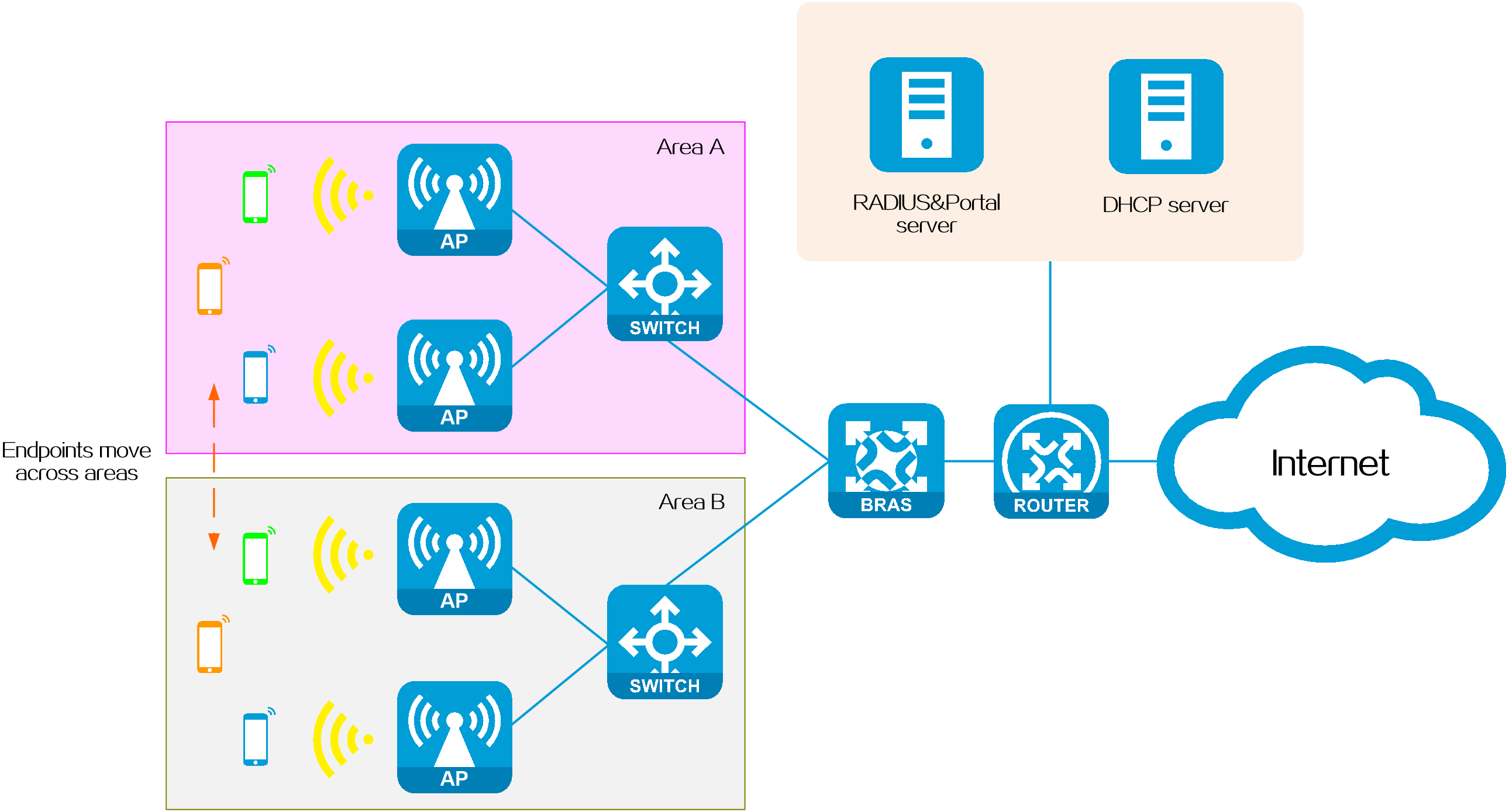
As mobile devices become more popular, public places like schools, companies, and hotels deploy Wi-Fi networks for wireless access. After IPoE users connect to a wireless network, they inevitably move between different areas. To improve network access experience, make sure users do not experience disconnections while moving between different areas. The IPoE Web user roaming feature effectively addresses this issue.
IPoE Web user roaming allows an IPoE Web user to stay online when moving among the specified areas covered by multiple wireless networks. Three IPoE Web user roaming methods are available: inter-VLAN roaming, inter-interface roaming, and inter-device roaming. You can limit the user roaming scope.
Figure 1 IPoE Web authentication user roaming
Technical benefits
· Users can seamlessly move between the specified areas covered by wireless networks without disconnections, which improves the network access experience.
· The roaming scope of users can be flexibly controlled as needed, allowing for managed and controlled roaming areas.
Operating mechanism
The basic process of IPoE Web user roaming is as follows:
1. After a user comes online through authentication on the source interface or VLAN, the user can roam from the source interface or VLAN in one area to the destination interface or VLAN in another area.
2. When the BRAS receives the user's ARP, IPv4, or IPv6 packets from the destination interface or VLAN, it checks the roaming policy set by the administrator to determine whether to allow the user to roam to the area of that destination interface or VLAN :
¡If allowed, the user's online session information is updated based on the destination interface or VLAN information. The user does not need reauthentication or reapplying for an address during the roaming process.
¡If not allowed, the user needs to perform re-authentication to come online on the destination interface or VLAN.
Roaming methods
Cross-VLAN roaming
· Application scenario: The BRAS divides different areas based on VLANs for user management and access control. For example, area A is VLAN 100, and area B is VLAN 200.
· Roaming method: IPoE users can roam between different VLANs on the same subinterface or between different VLANs on different subinterfaces on the BRAS.
Figure 2 Cross-VLAN roaming

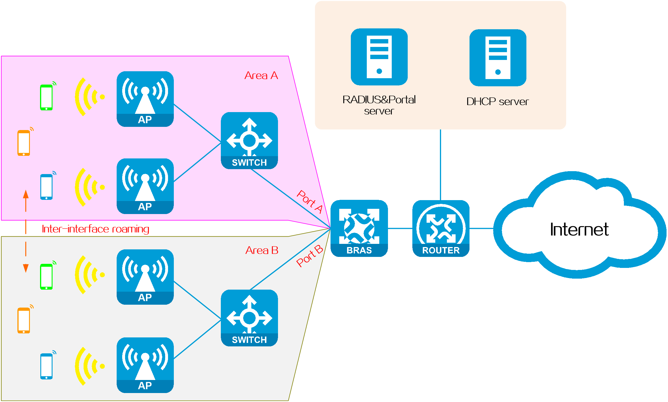
Cross-interface roaming
· Application scenario: The BRAS divides different areas based on interfaces for user management and access control. For example, users in area A access through Port A and users in area B access through Port B on the BRAS.
· Roaming method: IPoE users can roam between different interfaces on the same card or between different interfaces on different cards on the BRAS.
Figure 3 Cross-interface roaming
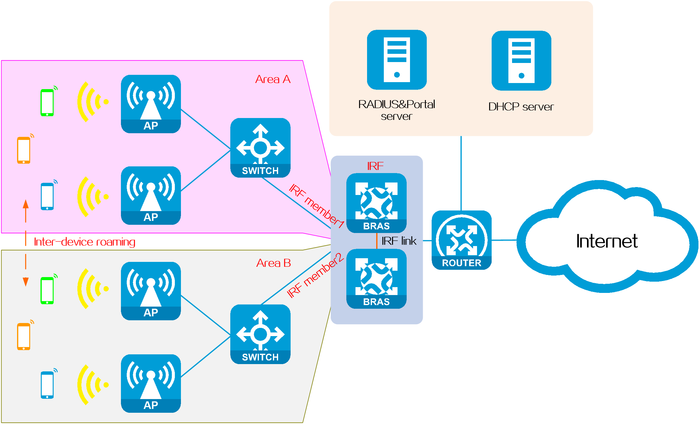
Cross-device roaming
· Application scenario: Two BRASs form an Intelligent Resilient Framework (IRF) fabric. The BRAS divides different areas based on IRF member devices for user management and access control. For example, users in area A access through IRF member device 1, and users in area B access through IRF member device 2.
· Roaming method: IPoE users can roam between different IRF member devices of the same IRF fabric.
Figure 4 Cross-device roaming
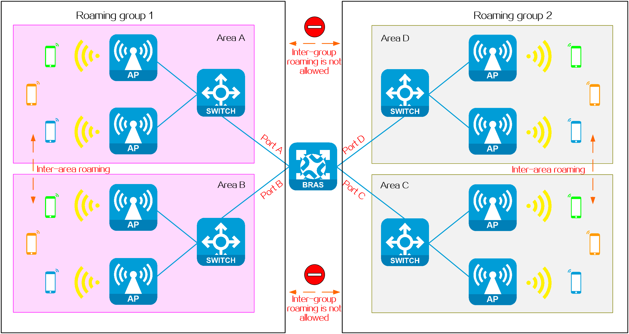
Controlling the roaming scope
In high-security networks, it is crucial to control the roaming scope of users. The users can roam only within the specified scope. When they go beyond the roaming scope, they must perform re-authentication to come online. To meet this requirement, deploy IPoE roaming groups to control the roaming scope of users.
An IPoE roaming group is a collection of interfaces among which IPoE Web users can roam. IPoE Web users can roam only among interfaces belonging to the same roaming group and cannot roam across different roaming groups. For example, if four interfaces (including Port A, Port B, Port C, and Port D) support user roaming on a BRAS. Port A and Port B belong to roaming group 1, and Port C and Port D belong to roaming group 2. Users who come online from any interface in roaming group 1 can only roam between Port A and Port B. Similarly, users who come online from any interface in roaming group 2 can only roam between Port C and Port D.
For an IPoE Web user to roam correctly, configure the interface before roaming and the interface after roaming as follows:
1. Enable IPoE for the same protocol stack.
2. Configure the same IPoE authentication method, authentication domain, roaming group, and Option79 trusting state (required only for DHCPv6 users).
This method is only applicable to Layer 2 access.
Figure 5 Controlling the roaming scope
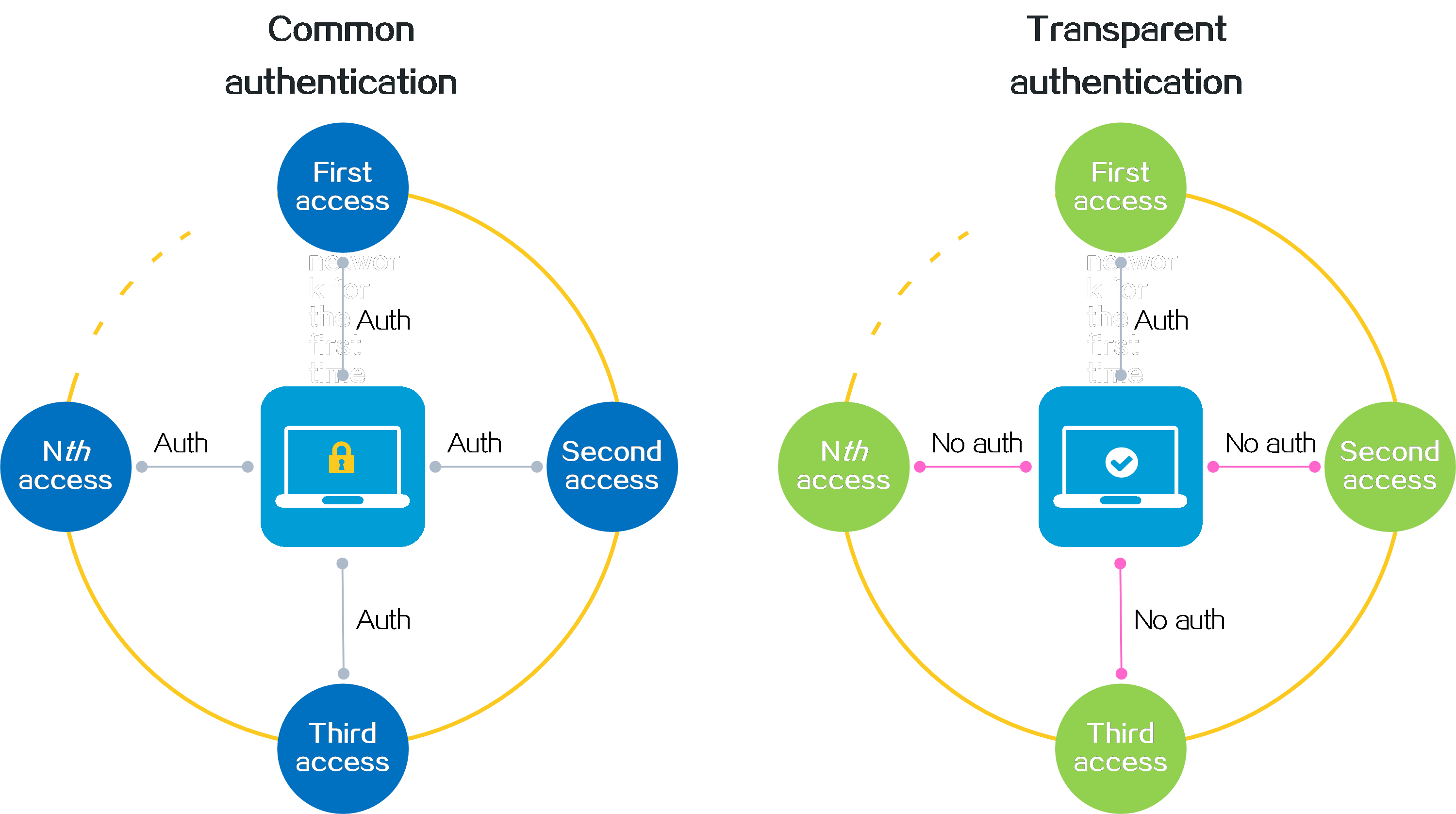
Transparent IPoE Web authentication
Introduction
IPoE Web authentication requires a user to manually enter the username and password on the authentication page of the browser for passing authentication. As networks continue to evolve and smart devices become more widespread, the traditional IPoE Web authentication method, which requires users to manually enter their usernames and passwords each time they come online, no longer meets the network access convenience requirements. To solve this problem, configure transparent IPoE Web authentication.
This feature provides MAC-based quick authentication. With this feature enabled, a user needs to enter the correct username and password only when accessing the network for the first time. Then, the user can directly access the network subsequently without entering the username or password. This feature implements "one authentication for forever use", which greatly simplifies the user operation and improves the user experience.
Figure 6 Transparent IPoE Web authentication
Technical benefits
· Simple operation, quick network access, and improved network access experience.
· High compatibility (compatible with almost all endpoints).
· Support for wired+wireless unified transparent authentication.
· Various transparent authentication types, which can be selected according to the network type (Layer 2 or 3 ) and server support for MAC binding.
Operating mechanism
Transparent IPoE Web authentication is implemented by the cooperation of common IPoE Web authentication and the MAC binding server. The detailed process is as follows:
1. When a user accesses the network for the first time, the user needs to enter the username and password for passing IPoE authentication on the authentication page that the BRAS pushes to the user.
2. After the user passes authentication, the bindings server automatically binds the user MAC address to the authentication information.
3. When the user accesses the network subsequently, the binding server directly completes authentication for the user according to the recorded binding. In this case, the device does not push an authentication page to the user. The user does not sense the authentication process. The user can quickly access the network without any operations
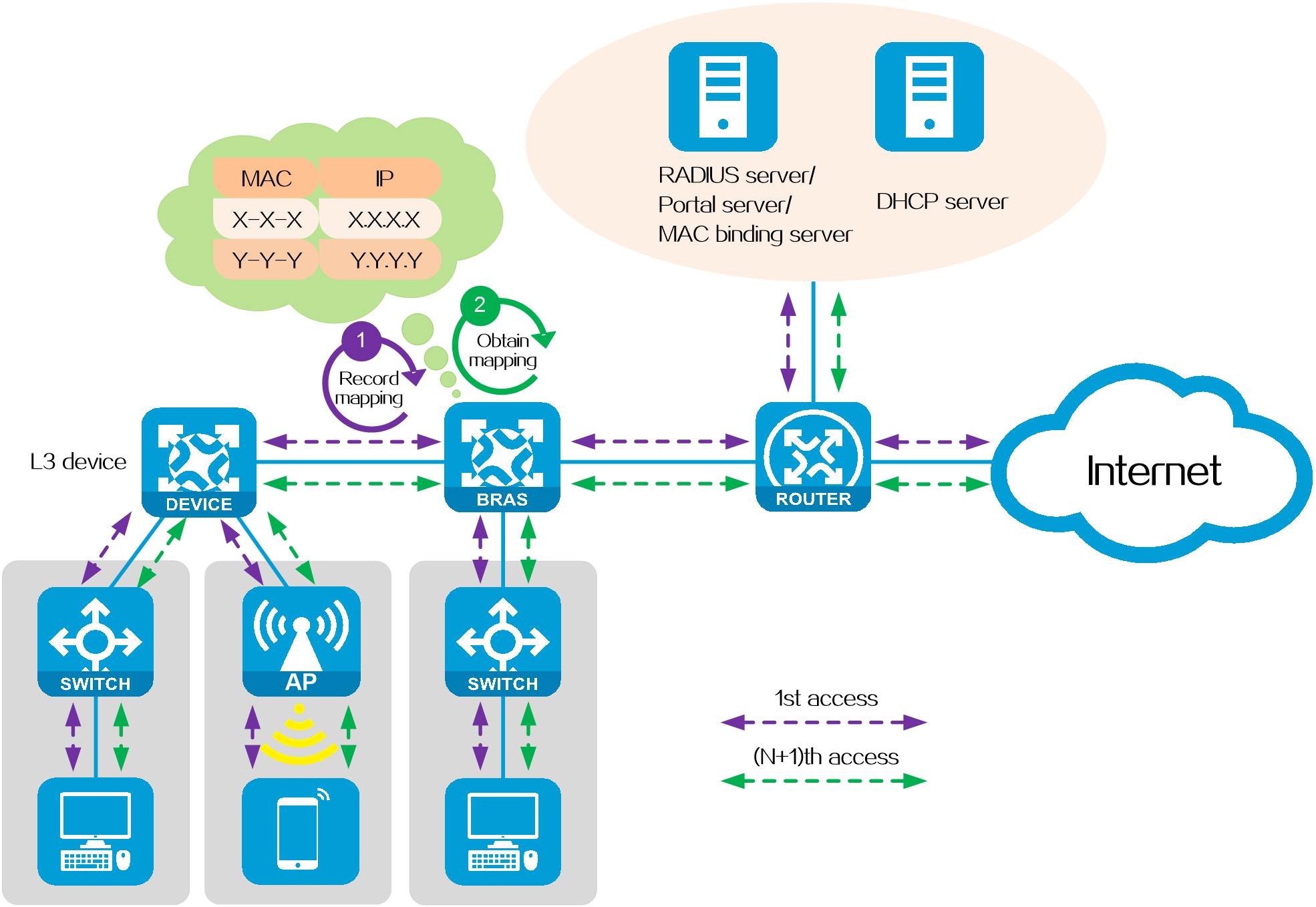
Layer 2/3 transparent authentication
IPoE Web authentication is divided into two types based on the presence of a Layer 3 device between the user and BRAS: Layer 2 transparent authentication and Layer 3 transparent authentication.
On a transparent authentication network, the BRAS must obtain the user's MAC address and send it to the authentication server. Based on this information, the server can determine whether the user meets the transparent authentication criteria.
· For Layer 2 transparent authentication, the BRAS can directly obtain the user's MAC address from the user's packets.
· For Layer 3 transparent authentication, the BRAS cannot directly obtain the user's MAC address from the user's packets due to the existence of a Layer 3 device between the user and BRAS. In such a scenario, the BRAS must obtain the user's MAC address as follows:
a. When the user comes online for the first time, the BRAS obtains the user's MAC address and IP address from the DHCP packets that assign the IP address to the user, and records the mapping between the MAC address and IP address.
b. When the user comes online for the second time or later, the BRAS uses the IP-MAC mapping to search for the MAC address corresponding to the user's IP address.
Figure 7 Layer 2/3 transparent authentication
|
|
NOTE: Layer 3 transparent authentication only supports the DHCP packet initiation mode, and other modes such as static session mode are not supported. |
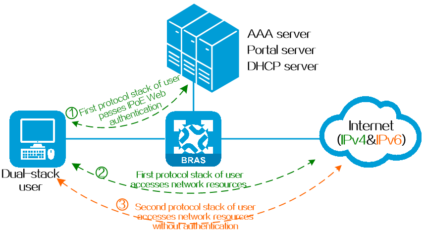
IPoE Web dual-stack authentication
Introduction
Dual-stack is one of the simplest and more user-friendly transition techniques among the many IPv4 to IPv6 transition technologies. In IPoE Web authentication, a dual-stack authentication means that when a dual-stack user is authenticated in one protocol stack (such as IPv4), the user is permitted to come online in the other protocol stack (such as IPv6) without authentication.
Based on the different ways in which users have their two protocol stacks come online, IPoE Web dual-stack authentication users are divided into three categories: dynamic dual-stack users, static dual-stack users, and mixed dual-stack users.
Figure 8 User authenticated in single stack and permitted in dual stack
Technical benefits
· For users, both protocol stacks come online through a single authentication process, improving the user experience.
· For servers, dual-stack authentication requires only one authentication process, reducing the load of AAA and portal servers.
· For administrators, treating the IPv4 and IPv6 protocol stacks of the same user as a single dual-stack user reduces the complexity of network management and maintenance.
Operating mechanism
The basic process of IPoE Web dual-stack authentication is as follows:
1. When a dual-stack user tries to come online in the first protocol stack (such as IPv4), the user enters the username and password on the authentication page. After successful authentication, the user can access the network resources of the protocol stack. The BRAS device records the user's MAC address, username, and authentication status.
2. When the user tries to come online in the second protocol stack (such as IPv6), the BRAS device checks whether the user has come online in the other protocol stack based on the user's MAC address. If it is online, the device permits the user in the second protocol stack without authentication.
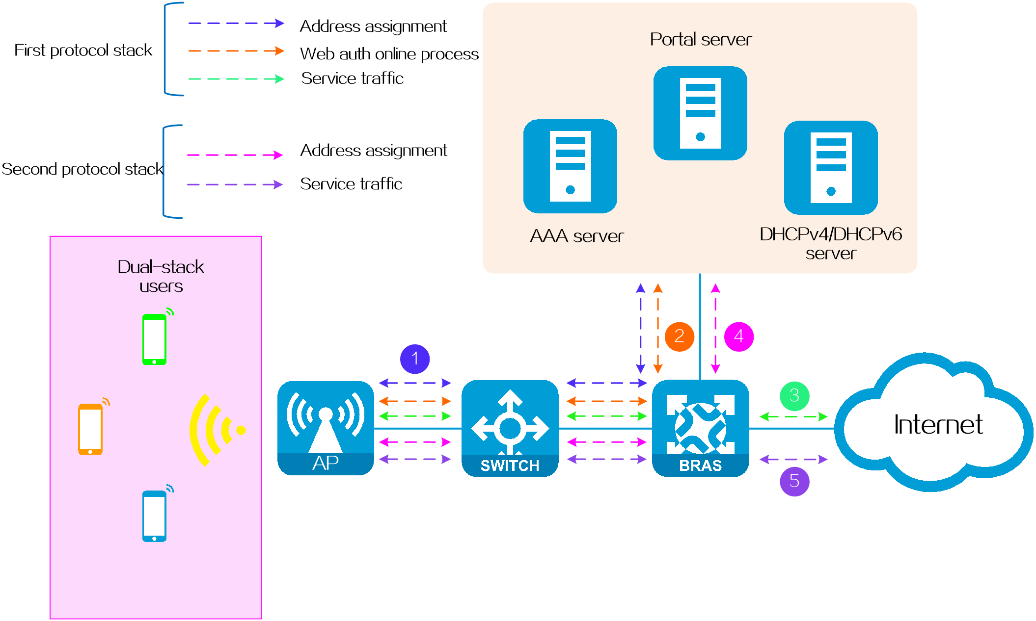
Dual-stack authentication types
Dynamic dual-stack authentication
Application scenario
This type is mostly used in scenarios where the mobile terminals of users do not have a fixed IP address. For example, students access the campus network through mobile terminals.
Operating mechanism
Both the IPv4 and IPv6 protocol stacks of this type of dual-stack user come online dynamically.
· In the IPv4 protocol stack: Users can trigger dynamic online authentication through DHCPv4 messages.
· In the IPv6 protocol stack: Users can trigger dynamic online authentication through DHCPv6 messages or ND RS messages.
Figure 9 Dynamic dual-stack authentication
|
|
NOTE: IPoE Web dual-stack authentication enables users and the BRAS device to communicate across a Layer 3 network. When crossing a Layer 3 network, a user's MAC address cannot be directly passed to the BRAS device. In this case, the BRAS device retrieves the user's MAC address from the chaddr field of the DHCPv4 message or Option 79 of the DHCPv6 message. |
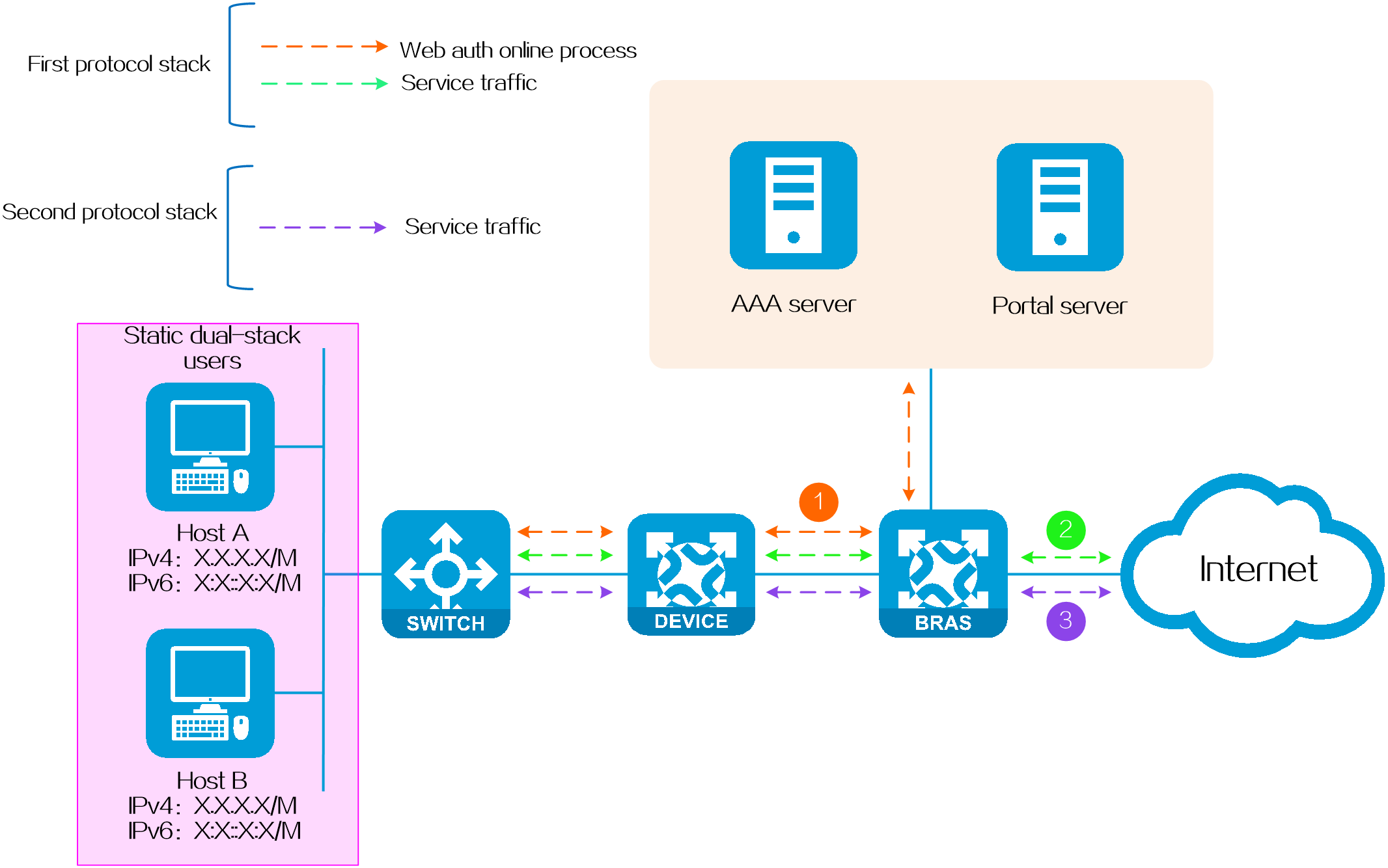
Static dual-stack authentication
Application scenario
It is often used in scenarios where the terminal IP address is fixed. For example, students access the campus network through a fixed network port in their dormitory.
Operating mechanism
Both the IPv4 and IPv6 protocol stacks of this type of dual-stack user come online in the static method.
· In the IPv4 protocol stack: Users can trigger online authentication statically by sending IPv4 packets or ARP packets.
· In the IPv6 protocol stack: Users can trigger online authentication statically by sending IPv6 packets, NS packets or NA packets.
Figure 10 Static dual-stack authentication
Hybrid dual-stack authentication
Application scenario
It is often used in scenarios where both fixed IP and non-fixed IP terminals exist in the network. For example, an IPv4 network of a university uses fixed IPv4 addresses. With the rise of IPv6, schools hope to upgrade the existing network so as to access IPv6 networks without changing the original IPv4 network deployment. At the same time, considering that IPv6 addresses are complex and inconvenient to remember, schools hope to dynamically allocate IPv6 addresses through DHCPv6, that is, using a mixed address allocation method of static IPv4 + dynamic IPv6.
Operating mechanism
One protocol stack of this type of dual-stack user comes online using the static method, and the other protocol stack comes online using the dynamic method.
Figure 11 Hybrid dual-stack authentication
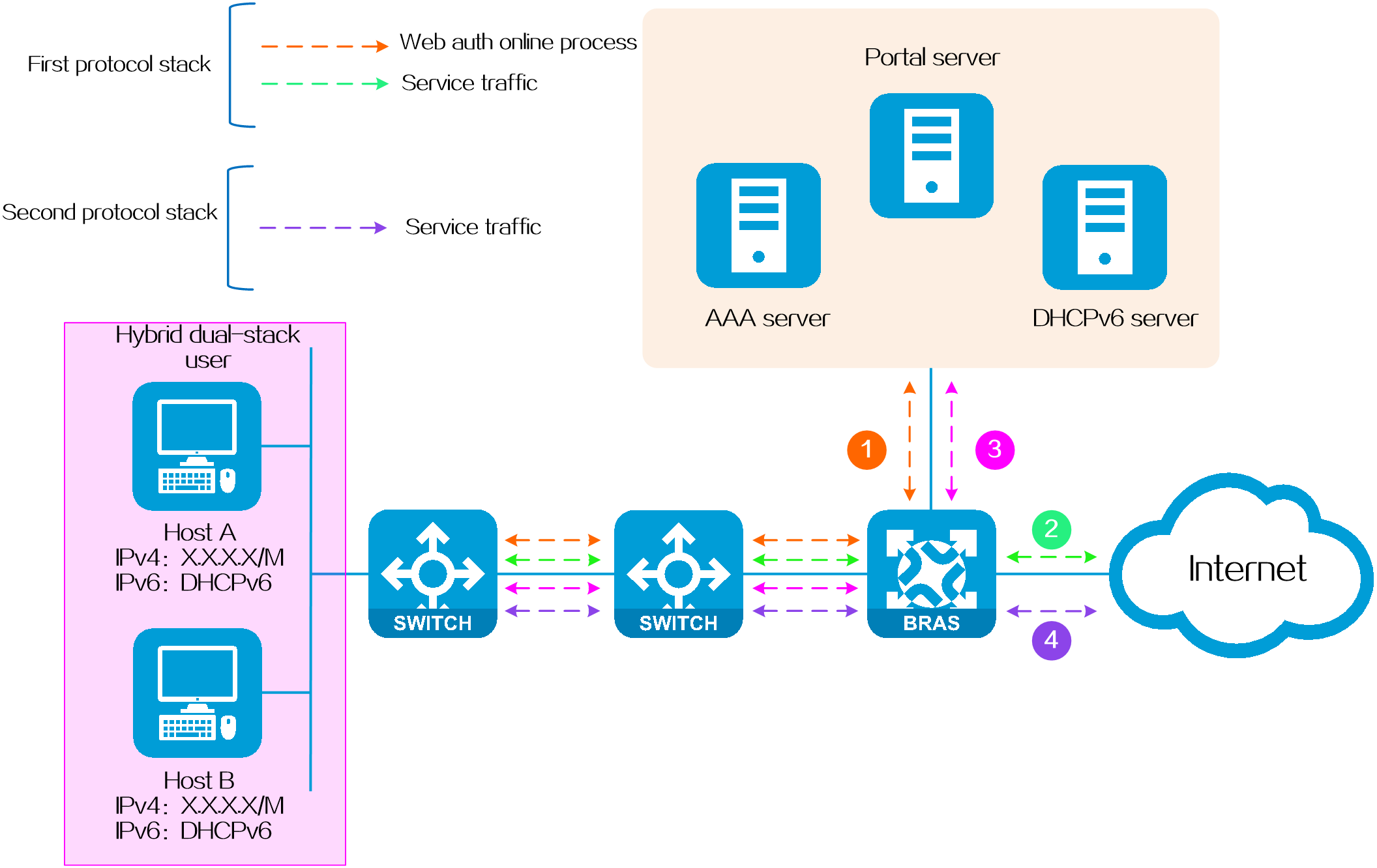
|
|
NOTE: · Only Layer 2 networking supports hybrid dual-stack authentication, while Layer 3 networking does not. · When a hybrid dual-stack user comes online, the stack in which the user comes online first is not determined. To ensure consistency in user attributes, you must configure the same usernames and authorization attributes for both stacks. This will prevent any user attribute inconsistencies when the dual-stack user first comes online in the IPv4 stack or the IPv6 stack. |
Compositions of IPv4/IPv6 online authentication triggers
The IPv4 and IPv6 protocol stacks of IPoE Web authentication users support multiple online authentication triggers. The table below shows the details.
Table 1 Support for compositions of IPv4/IPv6 online authentication triggers
|
IPv6 IPv4 |
IPv6 interface static user |
IPv6 global static user |
DHCPv6 |
NDRS |
IPv6 packets with unknown sources |
|
IPv4 interface static user |
Supported |
Not supported |
Not supported |
Not supported |
Not supported |
|
IPv4 global static user |
Not supported |
Supported |
Supported |
Supported |
Not supported |
|
DHCPv4 |
Not supported |
Yes |
Supported |
Supported |
Not supported |
|
IPv4 packets with unknown sources |
Not supported |
Not supported |
Not supported |
Not supported |
Not supported |
|
|
NOTE: Interface static user refers to a static user configured on a specific interface. A static user configured on an interface takes effect only on that interface. Global static user refers to a static user configured in system view. A global static user takes effect globally. Using global static user configuration together with interface parameters can meet all the application requirements for interface-level static users. As a best practice, use global static users. |
URL allowlist for IPoE Web authentication
Introduction
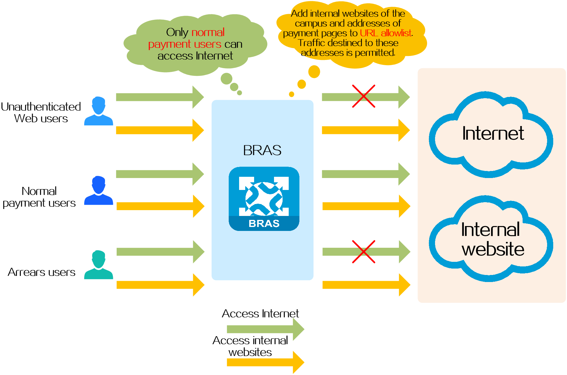
With this feature configured, the unauthenticated or defaulting users can still access the network resource list. For example, on a campus network that uses IPoE Web authentication, you can add the internal websites of the campus and the payment page of the service provider to the URL allowlist.
· When a student does not pass IPoE Web authentication or has passed IPoE Web authentication but has owed fees, the student is still allowed to access the internal websites of the campus. In this way, the student can still learn and communicate normally.
· When a student owes fees, the student is still allowed to access the payment page of the service provider and pay the charge on the payment page pushed by the service provider. In this way, the student can quickly restore access to Internet.
Depending on the application scenarios, the URL allowlists for IPoE Web authentication include IP-based URL allowlists and domain name-based URL allowlists.
Technical benefits
· Ensure that users can access the internal websites of the campus while effectively controlling their access to the Internet.
· Support local online payment for users' Internet access needs, with easy operation.
· Allow the addition of new URL addresses based on existing allowlist configurations. Configurations (such as QoS) are reused, making it easy to expand the allowlist.
· Support URL allowlist entries based on domain names and IP addresses, which you can choose flexibly as needed.
Operating mechanism
In IPoE Web authentication, the basic working process of URL allowlist is as follows:
1. QoS policies are deployed on the BRAS device to control access rights of normal payment and arrears users. The specific rules are as follows:
¡ Allow normal payment users' network traffic.
¡ Allow arrears users to access resources on the URL allowlist and the payment pages. The payment pages are pushed by the BRAS device when arrears users access resources not in the URL allowlist. Other access traffic of arrears users is discarded.
2. Before users pass Web authentication, they can only access the network resources specified in the URL allowlist.
3. After users pass Web authentication and come online, they can access network resources normally.
4. After the payment of a user is overdue, the AAA server issues a COA (Change of Authorization) message to the BRAS device, changing the authorization attribute of the user from normal payment user to arrears user. When arrears users access the Internet, the BRAS device pushes the payment page to require the users to pay.
5. After a user pays, the AAA server changes the user's Internet access rights from an arrears user to a normal payment user by COA, allowing the user to access network resources normally.
Figure 12 Schematic diagram
URL allowlist types
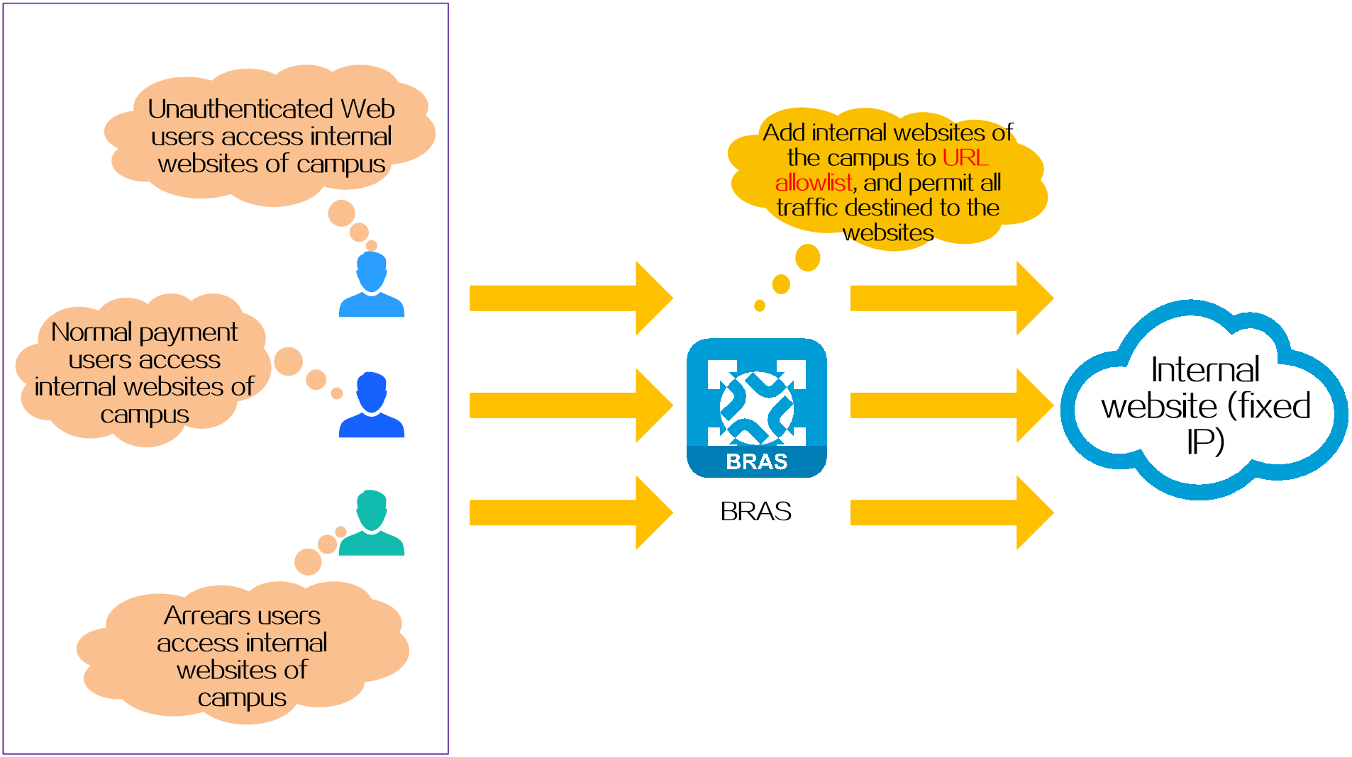
IP-based URL allowlist
Application scenarios
This type of URL allowlist specifies network resources with fixed IP addresses, for example, the internal websites of the campus.
Operating mechanism
Configure IP-based URL allowlist entries on the BRAS device, for example, https://x.x.x.x.edu.cn.
Benefits
This type does not require deployment of a DNS server on the network. Therefore, the configuration is relatively simple.
Figure 13 IP-based URL allowlist
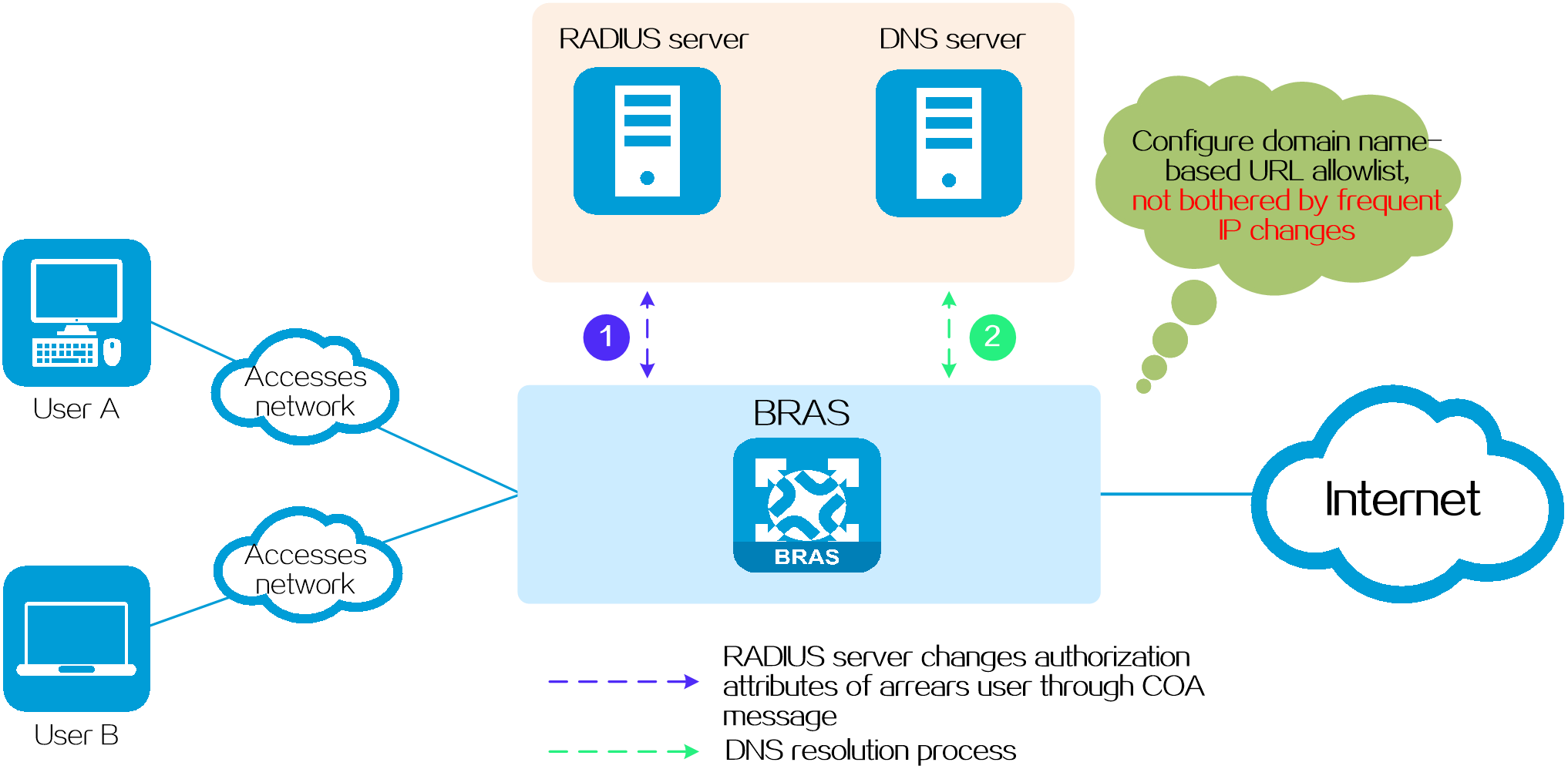
Domain name-based allowlist
Application scenarios
This type of URL allowlist specifies network resources whose IP addresses are not fixed. For example, when the payment of a student is overdue, the system needs to push a payment page to the student. For security purpose, the IP address of the payment page changes at intervals. To avoid frequent changes to the URL allowlist entry, you can add the domain name of the payment page to the URL allowlist.
Operating mechanism
On the BRAS device, configure a domain name-based URL allowlist entry (for example, https://abc.com/jiaofei), and then collaborate with a DNS server, which resolves the IP address dynamically.
Benefits
This method dynamically resolves IP addresses through DNS, which avoids frequent modifications to the URL allowlist configuration due to changes in IP addresses in the allowlist, making it easy to maintain.
Figure 14 Domain name-based allowlist
|
|
NOTE: The domain-based URL allowlist only supports exact domain name matching and does not support fuzzy domain name matching. The domain-based URL allowlist supports both exact domain name matching and fuzzy domain name matching. |
IPoE Web authentication security protection
Introduction
In networks where IPoE Web authentication is used, the following types of HTTP/HTTPS attacks might occur:
· Certain non-browser applications, such as chat software, online disk, etc., continue to send a large number of HTTP and HTTPS request packets to a fixed IP address.
· Maliciously attack endpoints on the Internet, continuously sending a large number of HTTP and HTTPS request packets to different IP addresses randomly.
As the IPoE Web authentication process is triggered by HTTP/HTTPS messages, illegal HTTP/HTTPS messages will be regarded as normal IPoE Web authentication requests. This will occupy a large amount of system resources, causing the performance degradation of the BRAS device and delaying the processing of authentication requests from legitimate users. As the IPoE Web authentication requires the cooperation of the portal server, a large number of illegal authentication requests will also decrease the performance of the portal server.
IPoE Web authentication supports multiple security protection measures to resolve the attack issues: Web attack prevention, Web noise reduction, and specifying the URLs to trigger the push of the Web authentication page.
Figure 15 Schematic diagram

Technical benefits
· Provide network security protection and enhance network security.
· Support multiple security measures to provide network security protection from different dimensions.
Security protection measures
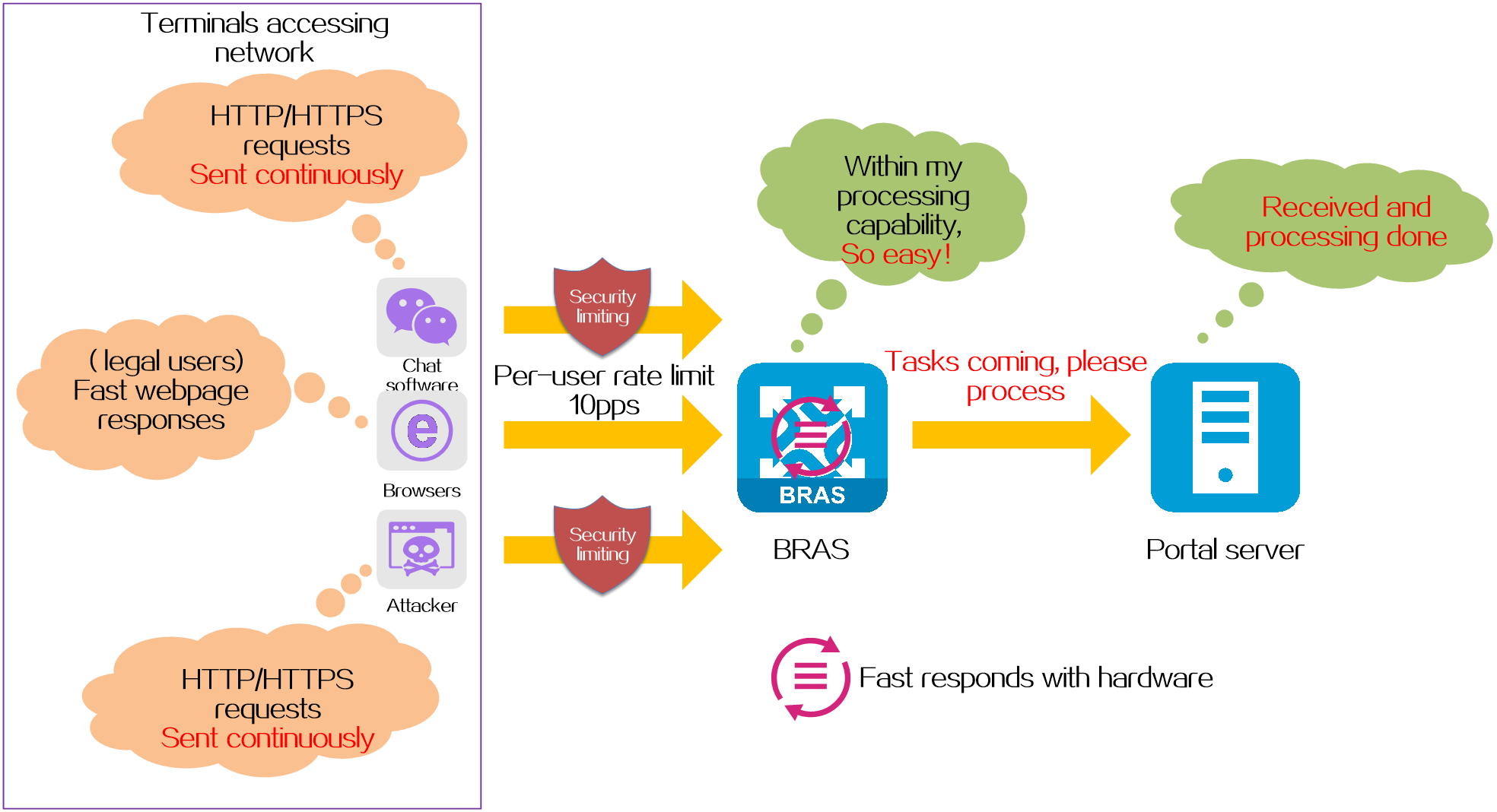
Web attack prevention
Protection targets
Protects the BRAS device and reduces the load on the portal server.
Protection mechanism
Uses the following anti-attack methods to intercept HTTP/HTTPS attack packets on the BRAS device.
· CAR for protocols of a single user—Limits the rate of all protocol packets sent by each user on the BRAS device, discards the packets that exceed the rate limit, and thus controls the overall receiving rate of protocol packets within the range that the BRAS device can bear.
· Fast responses to HTTP packets—The BRAS device identifies HTTP requests through hardware and automatically responds the requests, reducing the burden on the CPU and avoiding being a target of denial of service attacks.
· Destination IP-based HTTP/HTTPS attack defense—The BRAS device will monitor and collect statistics of HTTP/HTTPS packets sent by unauthenticated users to any destination IP address. If the total number of HTTP/HTTPS packets sent to a destination IP address within a statistics collection interval exceeds the specified threshold, the device determines an attack has occurred. Then, the device blocks attack packets or outputs attack logs as configured.
Figure 16 Web attack prevention
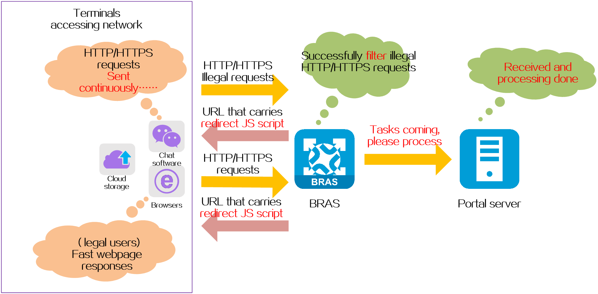
Web noise reduction
Protection targets
Protects the portal server from HTTP/HTTPS redirects initiated by non-browsers such as chat software and cloud storage.
Protection mechanism
The BRAS device uses its built-in redirect JS script to implement Web noise reduction.
Web noise reduction works as follows:
1. When the BRAS device receives an HTTP/HTTPS request packet from a terminal, it sends a URL redirect packet carrying the redirect JS script. These redirect URLs can only be recognized by standard browsers.
2. Terminals using standard browsers receive the redirect packet from the BRAS device, analyze the URL, and send a web authentication request to the specified portal server. Other terminals such as chat software and cloud storage are unable to recognize the redirect URLs and do not initiate Web authentication requests to the portal server.
Figure 17 Web noise reduction
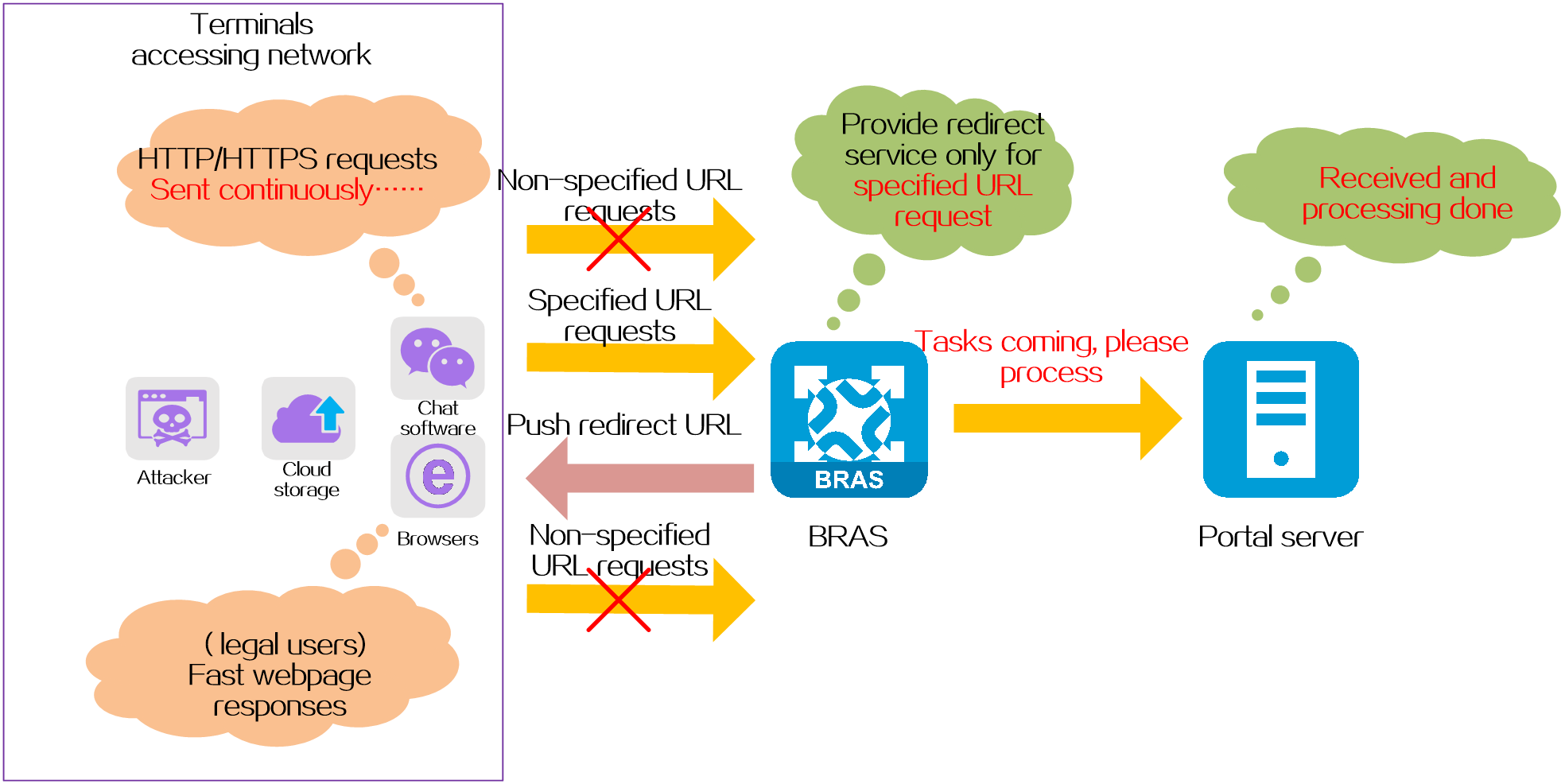
Specify the URL that can trigger pushing of the Web authentication page
Protection targets
Protects the BRAS device and reduces the load on the portal server.
Protection mechanism
Normally, when the BRAS device receives an HTTP/HTTPS request sent from a terminal to any destination IP address, it pushes a redirect Web authentication page to the terminal. In networks that require high security, you can specify the URL that can trigger pushing of a Web authentication page on the BRAS device. After deploying this function, the BRAS device will only push a Web authentication page for terminals accessing the specified URL, and directly discard HTTP/HTTPS requests accessing other URLs.
Figure 18 Specify the URL that can trigger pushing of the Web authentication page
Comparison of security protection measures
Table 2 Comparison of security protection measures
|
Attack prevention methods |
Protection targets |
Redirect for any URL request |
Redirect for fixed URL requests |
Fixed dest IPs attack prevention |
Random dest IPs attack prevention |
|
Web attack prevention |
BRAS device Portal server |
Supported |
Not supported |
Supported |
Supported |
|
Web noise reduction |
Portal server |
Supported |
Not supported |
Not supported |
Not supported |
|
Specify the URL that can trigger pushing of the Web authentication page |
BRAS device Portal server |
Not supported |
Supported |
Supported |
Supported |
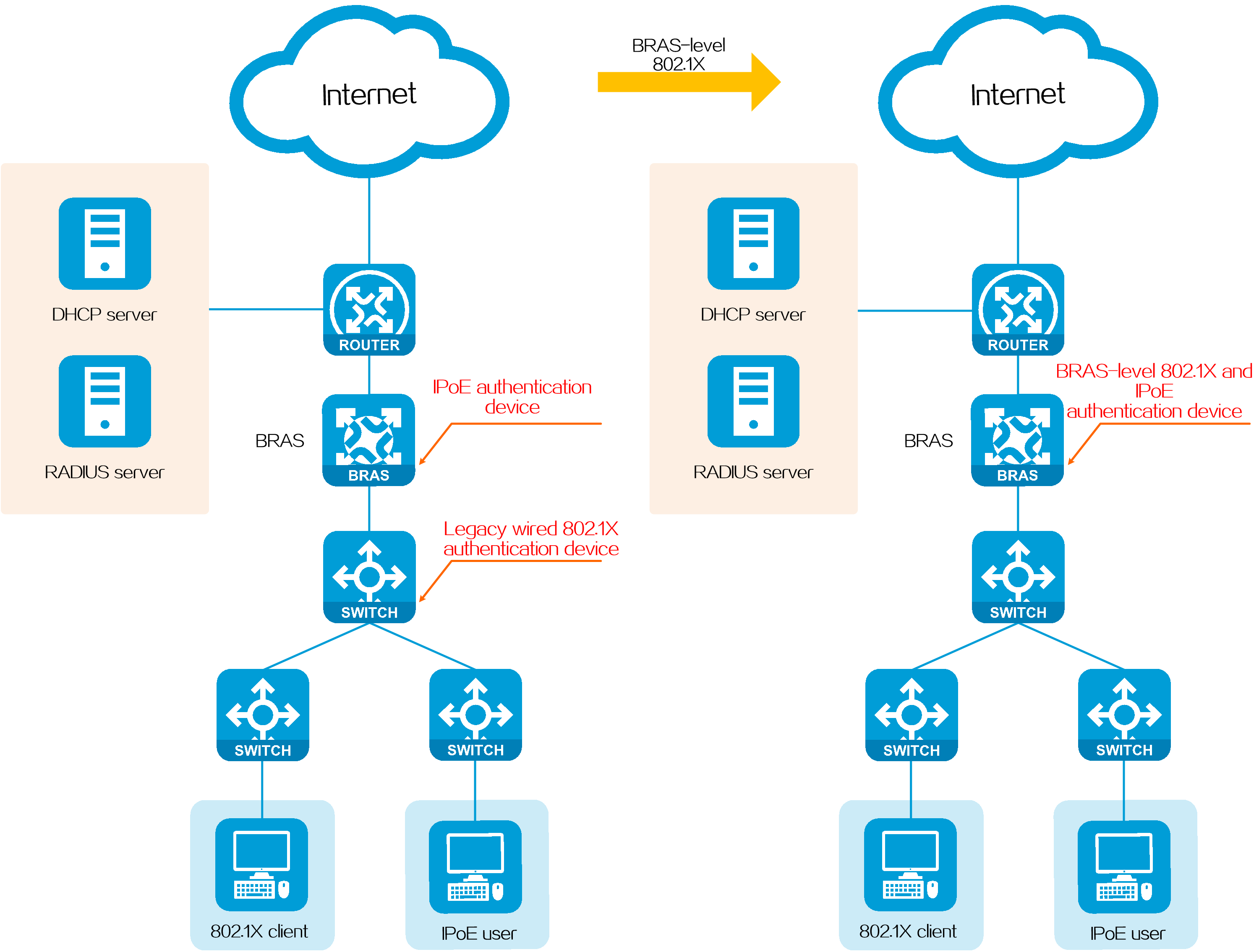
BRAS-level 802.1X authentication
Introduction
Traditional wired 802.1X is a network access control protocol based on Layer 2 interfaces, typically deployed on access or aggregation switches. Traditional BRAS access methods such as IPoE are Layer 3 interface-based network access control protocols, typically deployed on BRASs. On a hybrid network where both 802.1X authentication and traditional BRAS authentication are required, deploying 802.1X directly on the BRAS and supporting coexistence with other BRAS access methods such as IPoE can bring the following benefits:
· Allows administrators to flexibly deploy one or multiple access methods on the BRAS as needed.
· Allows administrators to manage both 802.1X users and BRAS users on the same BRAS, simplifying network management and reducing operations costs.
BRAS-level 802.1X authentication provides wired 802.1X access authentication on a BRAS. It uses 802.1X as an authentication method for IPoE, and enables 802.1X and IPoE to work together to provide 802.1X access on the BRAS.
Figure 19 BRAS-level 802.1X authentication
Technical benefits
· Allows administrators to flexibly deploy one or multiple access methods on the BRAS as needed.
· Allows administrators to manage both 802.1X users and BRAS users on the same BRAS, simplifying network management and reducing operations costs.
Operating mechanism
BRAS-level 802.1X authentication supports DHCP users, IPv6 ND RS users, and static users. The authentication process includes two phases, including preauthentication and postauthentication.
Based on whether 802.1X authentication is prioritized, the following situations exist:
· If 802.1X authentication is not prioritized, the following rules apply:
¡An IPoE user can perform authentication to come online no matter whether the 802.1X client of the IPoE user is authenticated.
¡An 802.1X user must perform IPoE preauthentication and 802.1X postauthentication to come online.
· If 802.1X authentication is prioritized, the following rules apply:
¡An IPoE user cannot perform authentication to come online before the 802.1X client of the IPoE user is authenticated.
¡An 802.1X user only needs to perform one authentication on the 802.1X client.
|
|
NOTE: On an actual network, you can select whether to prioritize 802.1X authentication as needed. |
802.1X authentication not prioritized
When 802.1X authentication is not prioritized, the basic process of BRAS-level 802.1X authentication is as follows:
· In the preauthentication phase:
The user access procedure in the preauthentication phase is the same as the user access procedure in the bind authentication mode. This phase does not involve 802.1X authentication.
· In the postauthentication phase:
After an IPoE user comes online in the preauthentication domain, the system determines the processing method in the postauthentication domain according to the authentication result of the 802.1X client as follows:
¡If the 802.1X client of the user is already online, IPoE uses the 802.1X authentication result to have the user come online directly in the postauthentication domain. In this case, the recorded user information is the 802.1X user information, including the 802.1X username, authentication domain, and authorized attributes.
¡If the 802.1X client of the user is not online, the IPoE user stays in the preauthentication phase. When the 802.1X client of the user comes online, the processing is the same as that in the previous step.
¡When both 802.1X authentication and Web authentication are configured on an interface, the following rules apply:
- If an IPoE user has come online in the postauthentication domain through Web authentication before the 802.1X client comes online, the device will force the user to return to the preauthentication domain from the postauthentication domain of Web authentication after the 802.1X client comes online. Then, the user will use 802.1X authentication to come online in the postauthentication domain of 802.1X authentication.
- After an IPoE user uses 802.1X authentication to come online in the postauthentication domain, the user cannot use Web authentication to come online in the postauthentication domain.
802.1X authentication prioritized
When 802.1X authentication is prioritized, the basic process of BRAS-level 802.1X authentication is as follows:
· When an IPoE user tries to come online in the
preauthentication phase:
If the 802.1X client of the IPoE user is not online, the IPoE user will stay in
the state before the preauthentication phase.
After the 802.1X client of the user comes online, IPoE uses the 802.1X
authentication result to have the user come online directly in the
postauthentication domain. In this case, the recorded user information is the
802.1X user information, including the 802.1X username, authentication domain,
and authorized attributes.
· When an IPoE user tries to come online in the preauthentication phase, IPoE uses the 802.1X authentication result to have the user come online directly in the postauthentication domain if the 802.1X client of the IPoE user is already online. In this case, the recorded user information is the 802.1X user information, including the 802.1X username, authentication domain, and authorized attributes.
· When an IPoE user tries to come online in the preauthentication phase, the IPoE user continues to come online through the IPoE authentication process if the 802.1X client of the IPoE user fails to pass authentication. In this case, the recorded user information is the IPoE user information, including the IPoE username, authentication domain, and authorized attributes.
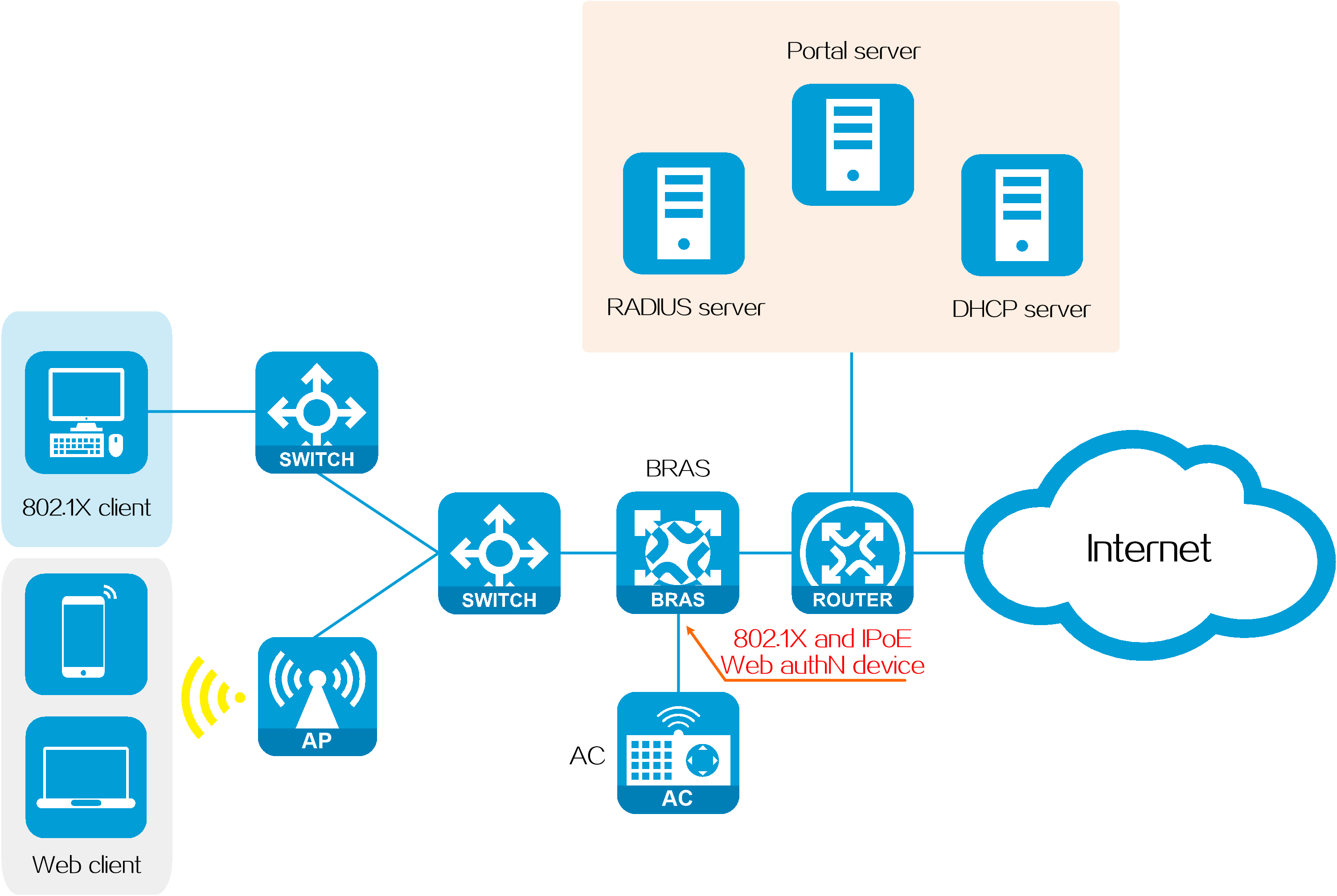
Co-existence of BRAS-level 802.1X authentication and IPoE Web authentication
On some networks, traditional wired 802.1X authentication is used due to historical reasons. However, as the network grows and mobile smart endpoints become more popular, an upgrade is desired while maintaining current 802.1X user habits. The upgrade must meet the new requirements for wireless IPoE Web access and simplify the network structure for future management. To meet the wired/wireless hybrid network requirements, deploy both BRAS-level 802.1X authentication and IPoE Web authentication on the BRAS.
· BRAS-level 802.1X authentication replaces traditional wired 802.1X authentication deployed on switches, and provides access services for wired 802.1X clients.
· IPoE Web authentication provides wireless access services for mobile smart endpoints.
· The BRAS uniformly manages authentication information for both wired and wireless users, and simplifies network management and maintenance.
Figure 20 Co-existence of BRAS-level 802.1X authentication and IPoE Web authentication
|
|
NOTE: When the BRAS has both BRAS-level 802.1X authentication and IPoE Web authentication configured on a specific interface, each user coming online through that interface can select only one authentication method at a time. Additionally, BRAS-level 802.1X authentication takes priority over IPoE Web authentication. |
Co-existence of BRAS-level 802.1X authentication and wireless 802.1X authentication
· RADIUS proxy not deployed
On a wired/wireless hybrid network as shown in Figure 21, the BRAS can provide BRAS-level 802.1X authentication for wired clients, and the access controller (AC) can be attached to the BRAS to provide 802.1X authentication for wireless clients. This setup meets the requirements of a wired/wireless hybrid 802.1X network.
Figure 21 RADIUS proxy not deployed

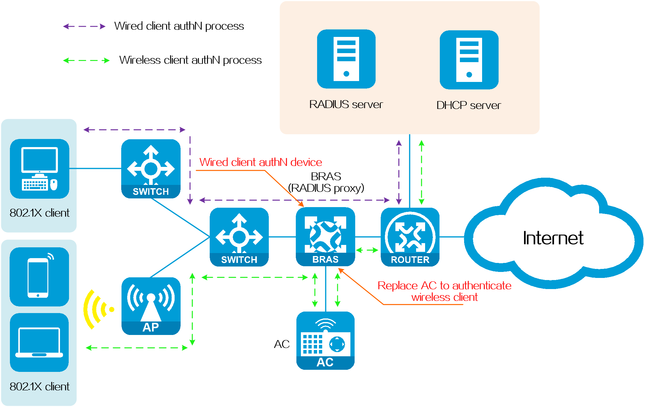
· RADIUS proxy deployed
In the hybrid network with RADIUS proxy deployed as shown in Figure 21, the wired 802.1X authentication point is the BRAS, and the wireless 802.1X authentication point is the AC. As a result, the authentication information for wired users and that for wireless users are stored on different devices, leading to complex user information management and inconsistent user access policies.
Deploying the RADIUS proxy on the BRAS effectively solves this problem. As shown in Figure 22, after the RADIUS proxy is deployed on the BRAS, the BRAS replaces the AC to interact with the RADIUS server. In this case, the BRAS completes the authentication process, maintains wireless user authentication/authorization information, and notifies the AC of the authentication result. Subsequently, IPoE performs traffic statistics collection and accounting. In this way, unified authentication and management of wired and wireless users is achieved on the BRAS.
Figure 22 RADIUS proxy deployed
PPPoE agency
Introduction
To meet the diverse requirements of campus network users for a variety of network egresses, improve user satisfaction, and simplify the campus network construction and maintenance, an increasing number of universities are choosing to cooperate and jointly operate with multiple ISPs to establish multiple network egresses. In this way, the choice of network egresses is delegated to students, and students can select and activate broadband accounts from different ISPs as needed.
In a joint operation scenario, deploying PPPoE agency on the campus BRAS can help improve BRAS service deployment efficiency, simplify the joint operations model, and provide excellent network access experience for campus network users.
With the PPPoE agency technology, the campus BRAS initiates agency dial-up authentication to the BRAS of the user's ISP for a campus user who has subscribed to the agency service of the ISP.
|
|
NOTE: The agency service generally refers to the network access service of activating broadband accounts provided by ISPs. |
Technical benefits
· For schools:
¡Simplifies the construction and maintenance of campus networks.
¡Meets the growing requirements of high-bandwidth and high-traffic applications by campus users.
¡Provides the schools with full control over the campus network and ensures network security.
¡Facilitates seamless integration of the existing AAA systems between the ISP and the school without integration development workload, and protects previous investments.
· For students:
¡Provides multiple ISPs for selection and provides a better network access experience and service.
¡Allows single login for both campus and ISP network authentication, and makes network access simple and convenient.
¡Supports unified wired and wireless access for campus users.
· For ISPs:
¡Supports one account per student, allows ISPs to provide different bandwidth values based on user tariffs, increases customer account openings, and ensures return on investment (ROI).
¡Provides a flexible solution, reduces system integration, and improves BRAS service deployment and agency service deployment efficiency.
¡Clearly demarcates responsibilities with the cooperation boundary at the campus network egresses, and allows the ISPs and the school to each do their own jobs.
Typical networks
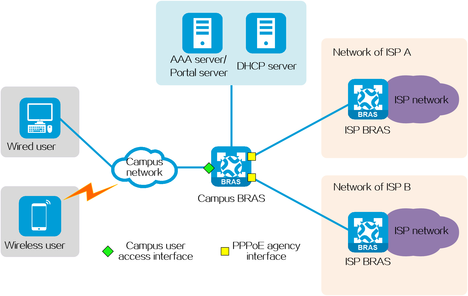
As shown in the following diagram, the PPPoE agency network contains the following components:
· Campus user—User who accesses the campus network by using IPoE or PPPoE.
· Campus BRAS—Provides BRAS access services and PPPoE agency services for campus users. The interfaces on the campus BRAS include the following types:
¡Campus user access interface—Provides BRAS access services for campus users on the campus BRAS. On a PPPoE agency network, the campus network administrator deploys QoS policies on the campus BRAS to control access permissions for campus users. When campus users use their campus accounts to perform authentication to come online on this interface, they can access only the campus network, and cannot access the external network.
¡PPPoE agency interface—Provides the agency dialup services for campus users who have subscribed to the agency service with the ISP on the campus BRAS. When these users use their campus accounts to perform authentication and come online on the campus BRAS, the campus BRAS automatically sends agency authentication requests to the corresponding ISP BRASs through the PPPoE agency interface. Once the authentication is successful, the users can access the external network through their ISPs.
· Campus DHCP server—Dynamically assigns IP addresses to campus access authentication users.
· Campus AAA server—Interacts with the campus BRAS to complete authentication, authorization, and accounting for users.
· Campus portal server—Server-side system that receives authentication requests from campus users, provides the Web authentication page to campus users, and exchanges user authentication information (username and password) with the campus BRAS to authenticate campus users.
· ISP BRAS—Provides BRAS access services for PPPoE agency on the campus BRAS.
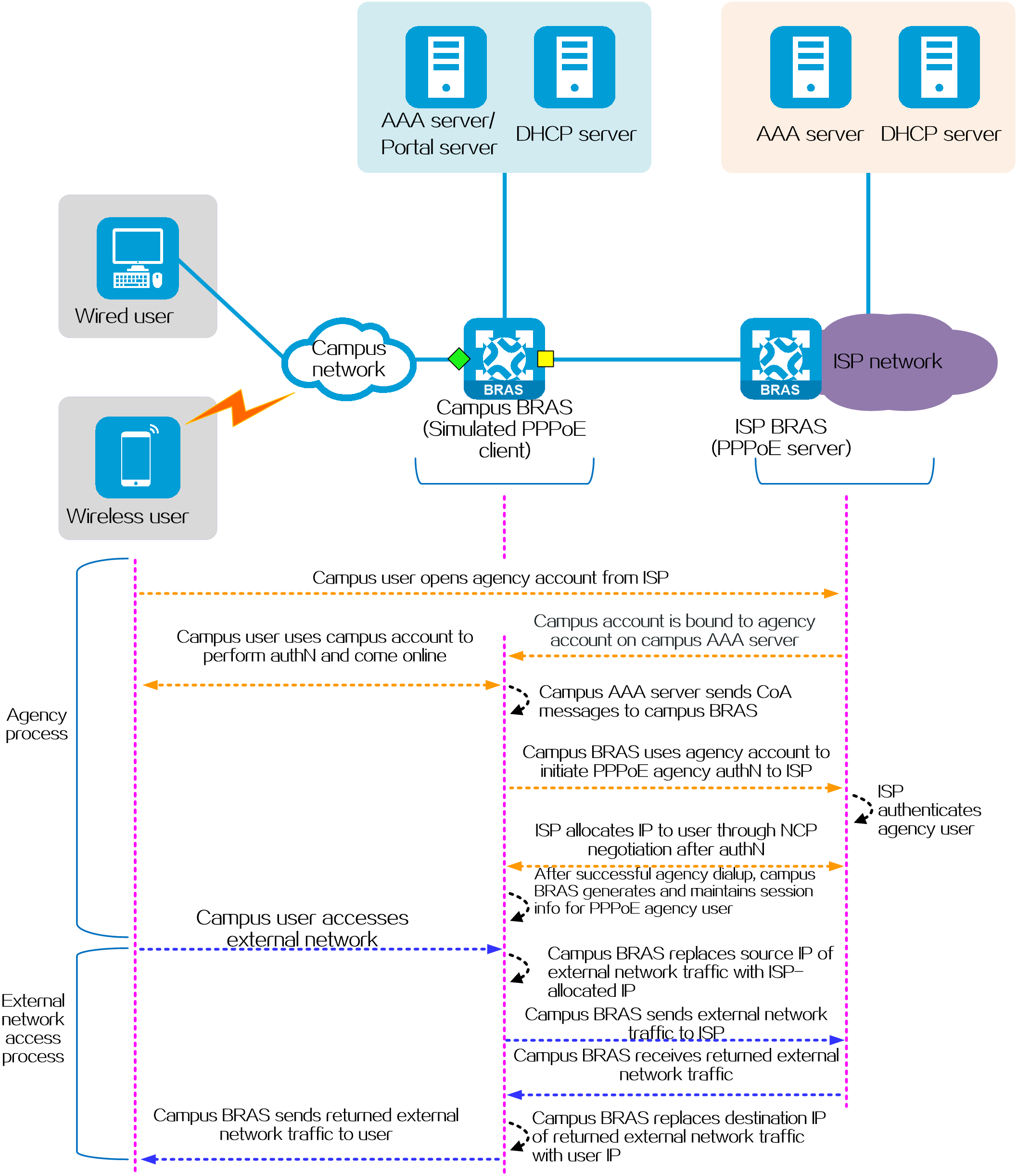
Figure 23 Typical networks
Operating mechanism
The basic process of PPPoE agency is as follows:
1. Campus users subscribe to the ISP agency service from ISPs. The provided ISP agency accounts are bound to their campus accounts on the campus AAA server. The binding operation can be done by campus users or by the campus network administrator after campus users report their accounts, depending on the campus AAA server capabilities.
2. After campus users use their campus accounts to pass authentication on the campus BRAS, the BRAS will maintain both campus access authentication user and PPPoE agency user identities for each user who has subscribed to the agency service. The BRAS processes traffic for these users as follows:
¡For internal network traffic of campus users, the BRAS directly permits the traffic to pass through as the traffic of campus access authentication users (for example, IPoE users).
¡For external network traffic of campus users, the BRAS processes the traffic as the traffic of PPPoE agency users.
3. When the campus AAA server receives the Accounting Start message about a user sent by the campus BRAS, the AAA server will notify the campus BRAS to initiate PPPoE agency for the accounting user through a CoA message, which carries the information such as the agency account opened by the user.
4. The campus BRAS simulates a PPPoE client by using the agency account information in the CoA messages, and then initiates PPPoE agency to the corresponding ISP BRAS through the agency interface. The ISP BRAS acts as the PPPoE server.
5. The ISP authenticates the PPPoE agency user. After the user passes authentication, the ISP allocates an IP address and other information to the PPPoE agency user through NCP negotiation.
6. After a successful agency dialup, the campus BRAS generates and maintains session information for the agency user.
7. When the campus BRAS receives external network traffic from a user, it replaces the source IP address of the packets with the IP address allocated by the ISP to the agency user. Then, the campus BRAS forwards them to the corresponding ISP BRAS.
8. When the campus BRAS receives the returned external network traffic, the campus BRAS replaces the destination IP address with the internal network IP address of the user and then forwards the packets to the corresponding campus user.
Figure 24 Operating mechanism
Intelligent acceleration (ITA&EDSG)
Introduction
Intelligent acceleration dynamically increases the user's network access speed to meet diverse user bandwidth requirements. Intelligent Target Accounting (ITA) and Enhanced Dynamic Service Gateway (EDSG) techniques are used on the ISP BRASs to meet various intelligent acceleration requirements:
· ITA—Provides separate accounting and traffic control based on the destination addresses of users' traffic.
· EDSG—Identifies a specific flow from users and provides separate accounting and flexible rate limiting services for that flow.
Technical benefits
· Improves the user's Internet access experience
By providing bandwidth as needed and letting users pay for the experience, ITA and EDSG ensure the optimal Internet access experience for the user. For example, when a user is watching a high-definition video, the basic bandwidth can be temporarily increased to the required bandwidth level (such as 30 Mbps to 80 Mbps ) to ensure an optimal video watching experience. After the program is over, the user's available bandwidth can automatically drop to the basic bandwidth.
· Achieves differentiated operations and services for network bandwidth resources
By differentiating various service types according to the destination addresses, ITA and EDSG can implement differentiated rate limiting, scheduling, and accounting for different types of services. A large difference exists in the charging rates of Internet traffic and internal traffic. ITA and EDSG can distinguish and charge the two types of traffic according to different charging rate levels, ensuring the operating revenues of the local ISPs.
· Expands the ISPs' commercial values in the industry chain
Without changing the current network structure, ITA and EDSG can help ISPs meet users' differentiated bandwidth and content requirements, stimulating greater broadband consumption potential. At the same time, after a user uses the broadband acceleration feature, the user can obtain short-term value-added services through monthly accounting and per-use accounting. After long-term use, the user is likely to become a high-bandwidth user of an ISP.
Operating mechanism (ITA)
Fundamentals
ITA performs differentiated management of user access services based on destination addresses. ITA defines different charging rate levels for different destination addresses and provides traffic control functions.
Service processing flow
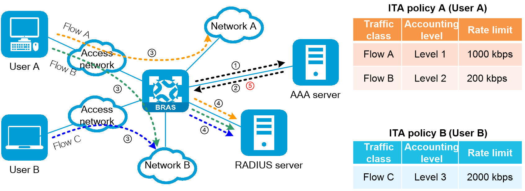
The ITA service processing flow is as follows:
1. The user initiates an online request to the BRAS, and the BRAS sends an authentication request to the AAA server.
2. The AAA server responds to the BRAS with an authentication success message and deploys an ITA policy to the user. The ITA policy specifies the charging rate level for separate accounting, rate limit parameters, and the separate accounting plan used. The number of traffic accounting levels configured for users varies by access method. For more information, see the configuration guides for your product.
3. When the user accesses the network after authentication, the BRAS identifies the flow that needs to be separately accounted and marks the flow with the corresponding accounting level based on the user profile authorized to the user or the QoS policy applied to the access interface.
4. For ITA flows, the BRAS sends accounting requests to the RADIUS accounting server in the ITA policy and performs accounting separately.
5. The ISP can use the AAA server to issue CoA messages to online modify the user's ITA policies.
Figure 25 Service processing flow
Operating mechanism (EDSG)
Fundamentals
The main function of EDSG is to provide separate accounting and dynamic rate limiting for the specified user flows. It identifies specific user flows and accounts them separately at different charging rates. EDSG also offers flexible dynamic traffic control.
Compared with ITA, EDSG has the following features:
· Flexible service expansion—Supports deploying multiple EDSG service policies to a single user. Different EDSG policies can use different authentication and accounting schemes, as well as different rate limiting policies.
· Dynamic policy deployment—Allows a user to increase bandwidth for a specific service flow and separately account the service flow by applying the corresponding EDSG policy after selecting a service. Once the service ends, the corresponding EDSG policy can be immediately canceled.
Service processing flow
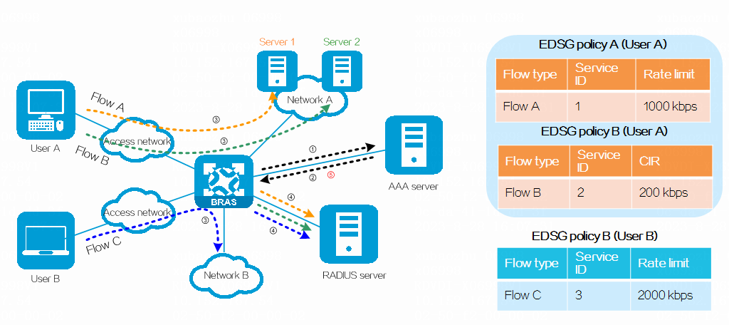
The EDSG service processing flow is as follows:
1. The user initiates an online request to the BRAS, and the BRAS sends an authentication request to the AAA server.
2. The AAA server responds to the BRAS with an authentication success message and deploys several EDSG policies to the user. Each EDSG policy specifies a service ID, a set of rate limit parameters, and an separate authentication/accounting scheme.
3. After the user accesses the network through authentication, the BRAS identifies different service flows based on the user profile authorized to the user or QoS policy applied to the access interface, and marks the service flows with the corresponding service IDs. Different service IDs can use different traffic charging rate levels.
4. If an separate EDSG authentication scheme is configured, the BRAS needs to initiate EDSG authentication requests for various services to the RADIUS authentication server specified in the EDSG policy. After a service passes EDSG authentication, the BRAS will initiate an separate EDSG accounting request to the RADIUS accounting server specified in the EDSG policy, and separately rate-limit it based on the EDSG authorization information of the service.
5. When a certain service ends, the ISP issues CoA parameters to the BRAS through the AAA server to cancel the specified EDSG policy to restore the initial rate limit parameters and accounting level for the user traffic.
Figure 26 Service processing flow
Technique comparison
Table 3 ITA vs EDSG
|
ITA |
EDSG |
|
Suitable for environments with few service policies, such as campus networks. |
Suitable for environments with multiple service policies and rich combinations, such as ISP networks. |
|
Supports authorizing service policies to users after they come online, and dynamically deploying service policies through CoA. |
Supports authorizing service policies to users after they come online, and dynamically deploying service policies through CoA. |
|
Only one service policy can be deployed to a user at a time. Each service policy can define multiple levels of service parameters, and the charging rates for services are defined by the BRAS. |
Multiple service policies can be deployed simultaneously to a user, with each policy having its own set of service parameters. The charging rates for services are defined by the server. |
|
Only online replacement of service policies is supported through CoA. |
Online adding, changing, and canceling of service policies are supported through CoA. |
|
Once a user is authenticated successfully, each level of service can be accounted separately, and separate authentication is not required or supported. |
· After successful authentication, each service can be authenticated separately before accounting, and can be authorized separate service parameters by the server. · Usernames and passwords for service authentication can be different from those used for user authentication. |
|
The service flows need to be marked with levels. |
The service flows need to be marked with service IDs. |
|
Accounting and rate limiting can be done separately for IPv4 and IPv6 traffic. |
Accounting and rate limiting can be done separately for IPv4 and IPv6 traffic. |
|
Only out-of-band rate limiting is supported. |
Two rate-limiting modes are supported: · In-band—Obtains the service flow bandwidth from the total user bandwidth, and affects normal service bandwidth after separate rate limiting. · Out-of-band—Rate-limits service flow bandwidth separately without using basic user bandwidth. |
|
Supports merging service flows of multiple levels into a single flow with the lowest level for unified accounting. |
Multiple service flows cannot be merged for accounting. |
|
By default, the BRAS reports all ITA service traffic as part of the user's total traffic to the accounting server. You can exclude the service flow of a specific level from the total traffic. |
By default, the BRAS does not report EDSG service flows as part of the user's total traffic to the accounting server. You can include a service flow of a specific ID in the total traffic. |
|
When a user's ITA service traffic is exhausted, the BRAS sends an accounting update message to the server to get a new quota. You can specify that the user goes offline or does not send accounting update messages. |
Once the EDSG service traffic of the user is exhausted, the service will stop. |
IRF BRAS hot backup
About IRF BRAS hot backup
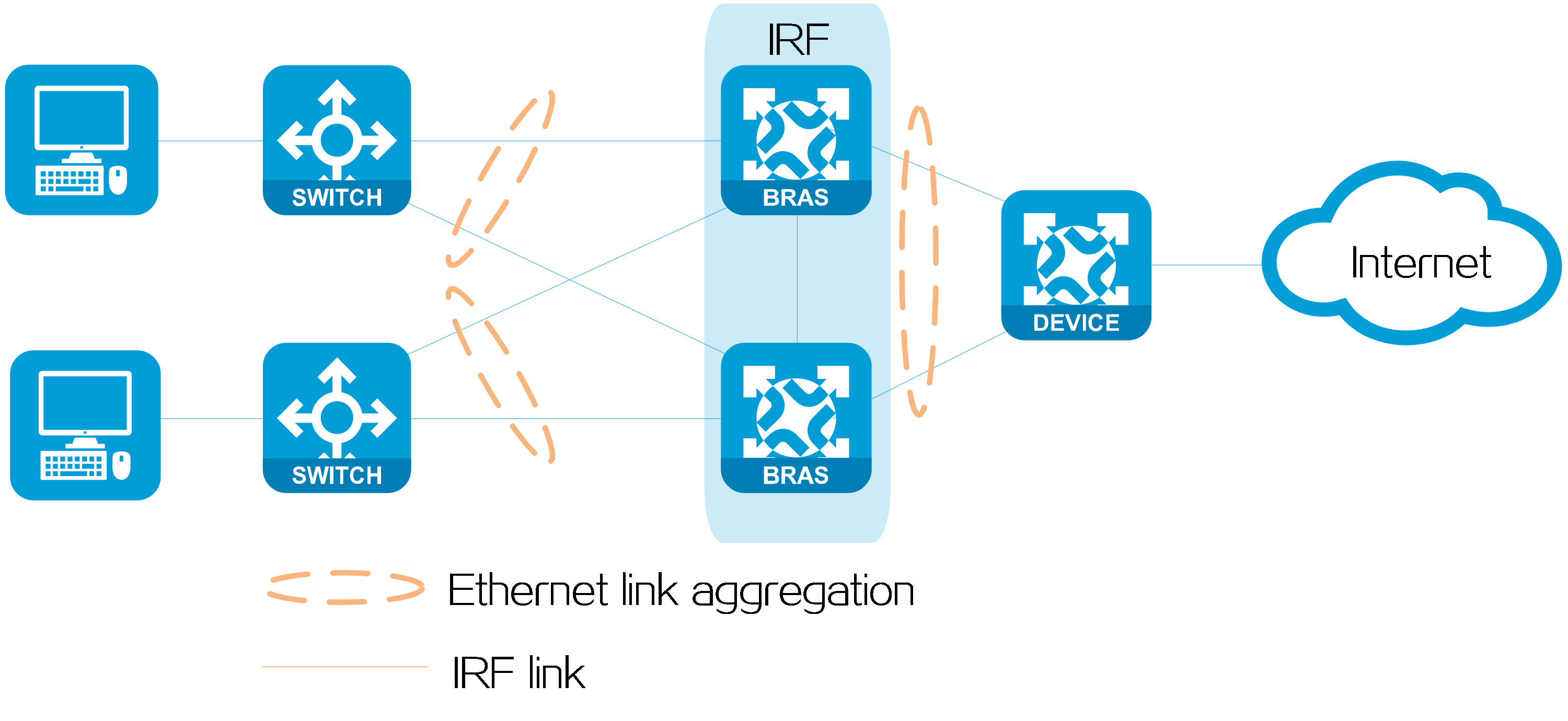
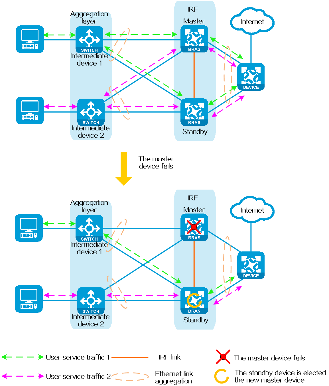
The Intelligent Resilient Framework (IRF) technology virtualizes two physical devices into a logical device called an IRF fabric. This technology offers processing power, interaction, unified management, and simplified maintenance of two devices. IRF BRAS hot backup uses this technology to provide node redundancy for BRAS. When the master BRAS device fails, the standby BRAS device can quickly take over the master role to provide services without interruption.
Figure 27 IRF BRAS hot backup
Benefits
· Simplified network topology—For the upstream and downstream devices of an IRF fabric that has two physical BRAS devices, the IRF fabric appears as one node. Although the physical connections connected to the BRAS devices remain unchanged, they transition from connecting two physical devices to connecting one logical device, which simplifies the network topology.
· Enhanced network scalability—As the number of BRAS access users increases, the demands for network ports and bandwidth continue to increase. IRF can increase port density by adding expandable service modules on BRAS devices. In conjunction with Ethernet link aggregation, IRF can also improve interface bandwidth. Additionally, because each member device can independently handle protocol packets and forward packets, IRF not only enables service expansion but also improves the service processing capability of BRAS devices.
· Simplifying network deployment—To improve the efficiency of master/standby switchover upon a failure, non-IRF BRAS hot backup typically requires multiple protection techniques between the master and standby systems depending on the network type. However, a BRAS IRF fabric is a logically unified system and does not require any additional protection techniques between the master and standby systems. By deploying an IRF fabric, the complexity of network deployment can be significantly reduced.
· Address resource conversation—Link aggregation is available for the physical links between an IRF fabric and its upstream or downstream devices. After multiple physical links are aggregated, you do not need to assign an IP address for each physical link. You only need to configure IP addresses on the aggregate interfaces, which effectively conserves IP address resources.
· Powerful multiservice capabilities—A single BRAS device can support various services, including PPPoE, IPoE, and L2TP. A BRAS IRF fabric not only inherits the powerful service capabilities of a single BRAS device, but also provides node-level redundancy for BRAS services.
· Enhancing network robustness—If a device or link fails before BRAS devices form an IRF fabric, traffic destined for the affected BRAS device cannot be switched over to other BRAS devices until route convergence is complete. After BRAS devices form an IRF fabric, links between the IRF fabric and its upstream or downstream devices are aggregated. When a device or link fails, traffic destined for the affected BRAS device can be quickly switched over to other BRAS devices through the aggregate link. The convergence is fast.
Operating mechanism
After two BRAS devices form an IRF fabric, the aggregation switches load share traffic among the aggregate links connected to the BRAS devices. Upon receiving traffic, both the master and standby BRAS devices can forward the traffic. When the master device fails, the system automatically elects a new master device. Then, the aggregation switches switch over all upstream traffic to the links connected to the new master device to ensure service continuity.
Figure 28 Operating mechanism
IP address acquisition methods
Introduction
This chapter introduces the common methods used for IP address acquisition in IPoE networks:
· (Layer 2 network) The BRAS acts as the DHCP server
· (Layer 2 network) The BRAS acts as the DHCP relay agent
· (Layer 3 network) The BRAS acts as the DHCP server
· (Layer 3 network) The BRAS acts as the Level 2 DHCP relay agent
· (Layer 3 network) The BRAS acts as neither of the DHCP server and the DHCP relay agent
The following concepts are used in this chapter:
· Preferred IPv4 address of an interface: If the interface is configured with a primary address, the primary address is selected as the preferred IPv4 address. If the interface is not configured with a primary address, the first secondary address displayed in the output of the display ip interface interface-type interface-number command is selected as the preferred IPv4 address. In this document, such a secondary address is called preferred secondary address.
· Preferred IPv6 address of an interface: This address refers to the first valid IPv6 global unicast address displayed in the output of the display ipv6 interface interface-type interface-number command.
· Ordinary IP address pool: IP address pool created by the ip pool pool-name command or the ipv6 pool pool-name command. This type of IP address pools can be further divided into the following:
¡ Ordinary local IP address pool—Ordinary IP address pool that is not configured with the remote-server command.
¡ Ordinary remote IP address pool—Ordinary IP address pool that is configured with the remote-server command.
· Local BAS IP address pool: IP address pool created by the ip pool pool-name bas local command.
· Remote BAS IP address pool: IP address pool created by the ip pool pool-name bas remote command.
(Layer 2 network) The BRAS acts as the DHCP server
Network configuration
As shown in Figure 29, the Layer 2 switch connects the host and the BRAS. The BRAS acts as the DHCP server for user address assignment.
Figure 29 The BRAS acts as the DHCP server on Layer 2 network

|
|
NOTE: In this networking model, you need to create an ordinary IP address pool or local BAS IP address pool on the BRAS, regardless of whether the IP address acquisition method is authorization address pool. For better readability, configurations of different IP address pools are introduced separately. You can see "IP address acquisition from ordinary local IP address pools" and "IP address acquisition from local BAS IP address pools". Each topic further introduces the restrictions and guidelines on using authorization address pools or non-authorization address pools for IP address acquisition. |
IP address acquisition from ordinary local IP address pools
Ordinary local IPv4 address pools
|
IP address acquisition method |
Restrictions and guidelines |
|
Authorization IP address pool |
· Do not configure IP addresses for the user-facing interface. · When you configure the gateway-list command in the authorization IP address pool, you must specify the export-route keyword. |
|
Authorization IP address pool group |
· Do not configure IP addresses for the user-facing interface. · When you configure the gateway-list command for any member of the authorization IP address pool group, you must specify the export-route keyword. |
|
Non-authorization IP address pool (either IP address pool or IP address pool group). The BRAS selects an IP address pool based on the preferred IPv4 address of the user-facing interface for user address assignment. |
· You must configure IP addresses for the user-facing interface. · If the user-facing interface is configured with a primary address, the BRAS selects an IP address pool based on the primary address. If the user-facing interface is not configured with a primary address, the BRAS selects an IP address pool based on the preferred secondary address. |
|
Non-authorization IP address pool (either IP address pool or IP address pool group). An IP address pool is applied to the user-facing interface of the BRAS by using the dhcp server apply ip-pool command. When the BRAS receives a DHCP request on the user-facing interface, it will use the IP address pool bound to that interface for user address assignment. |
· You must configure IP addresses for the user-facing interface. · When you apply an IP address pool to the user-facing interface, make sure the address pool must belong to the same network segment as the preferred IPv4 address of the interface. For example, if the interface is not configured with a primary address, the address pool must belong to the same network segment as the preferred secondary address of the interface. |
Ordinary local IPv6 address pools
|
IP address acquisition method |
Restrictions and guidelines |
|
Authorization IPv6 address pool |
· You must configure the ipv6 address auto link-local command to enable automatic link-local address generation on the user-facing interface. · Do not configure IPv6 global unicast addresses for the user-facing interface. |
|
Authorization IPv6 address pool group |
· You must configure the ipv6 address auto link-local command to enable automatic link-local address generation on the user-facing interface. · Do not configure IPv6 global unicast addresses for the user-facing interface. |
|
Non-authorization IPv6 address pool (either IPv6 address pool or IPv6 address pool group). The BRAS selects an IPv6 address pool based on the preferred IPv6 global unicast address of the user-facing interface for user address assignment. |
You must configure IPv6 global unicast addresses for the user-facing interface. |
|
Non-authorization IPv6 address pool (either IPv6 address pool or IPv6 address pool group). An IPv6 address pool is applied to the user-facing interface of the BRAS by using the ipv6 dhcp server apply pool command. When the BRAS receives a DHCPv6 request on the user-facing interface, it will use the IPv6 address pool bound to that interface for user address assignment. |
· You must configure IPv6 global unicast addresses for the user-facing interface. · When you apply an IPv6 address pool to the user-facing interface, make sure the interface has an IPv6 global unicast address that belongs to the same network segment as the address pool. The IPv6 global unicast address can be a non-preferred IPv6 address. |
|
Authorization ND prefix pool (Use this method when each user requires a different prefix.) |
· You must configure the ipv6 address auto link-local command to enable automatic link-local address generation on the user-facing interface. · Do not configure IPv6 global unicast addresses for the user-facing interface. |
|
Authorization ND prefix pool group (Use this method when each user requires a different prefix.) |
· You must configure the ipv6 address auto link-local command to enable automatic link-local address generation on the user-facing interface. · Do not configure IPv6 global unicast addresses for the user-facing interface. |
IP address acquisition from local BAS IP address pools
Local BAS IPv4 address pools
|
Restrictions and guidelines |
|
|
Authorization IP address pool |
Do not configure IP addresses for the user-facing interface. |
|
Authorization IP address pool group |
Do not configure IP addresses for the user-facing interface. |
|
Non-authorization IPv4 address pool (either IP address pool or IP address pool group). The BRAS selects an IP address pool based on the preferred IPv4 address of the user-facing interface for user address assignment. |
· You must configure IP addresses for the user-facing interface. · If the user-facing interface is configured with a primary address, the BRAS selects an IP address pool based on the primary address. If the user-facing interface is not configured with a primary address, the BRAS selects an IP address pool based on the preferred secondary address. |
|
Non-authorization IP address pool (either IP address pool or IP address pool group). An IP address pool is applied to the user-facing interface of the BRAS by using the dhcp server apply ip-pool command. When the BRAS receives a DHCP request on the user-facing interface, it will use the IP address pool bound to that interface for user address assignment. |
· You must configure IP addresses for the user-facing interface. · When you apply an IP address pool to the user-facing interface, make sure the address pool must belong to the same network segment as the preferred IPv4 address of the interface. For example, if the interface is not configured with a primary address, the address pool must belong to the same network segment as the preferred secondary address of the interface. |
Local BAS IPv6 address pools
This scenario is not supported, because BAS IPv6 address pools do not exist.
(Layer 2 network) The BRAS acts as the DHCP relay agent
Network configuration
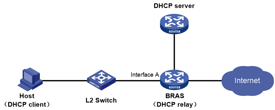
As shown in Figure 30, the Layer 2 switch connects the host and the BRAS. The BRAS acts as the DHCP relay agent to obtain user IP addresses from the remote DHCP server.
Figure 30 The BRAS acts as the DHCP relay agent on Layer 2 network
|
|
NOTE: In this networking model, you need to create an ordinary remote IP address pool or remote BAS IP address pool on the BRAS only if the IP address acquisition method is authorization address pool. If the IP address acquisition method is non-authorization address pool, you do not need to create any IP address pool on the BRAS. For better readability, configurations of different IP address pools are introduced separately. You can see "IP address acquisition from authorization address pools" and "IP address acquisition from non-authorization address pools". Each topic further introduces the restrictions and guidelines on using different types of address pools for IP address acquisition. |
IP address acquisition from authorization address pools
Ordinary remote IPv4 address pools
|
IP address acquisition method |
Restrictions and guidelines |
|
Authorization IP address pool Do not configure IP addresses for the user-facing interface. |
When you configure the gateway-list command in the authorization IP address pool, you must specify the export-route keyword. |
|
Authorization IPv4 address pool group |
· Do not configure IP addresses for the user-facing interface. · When you configure the gateway-list command for any member of the authorization IP address pool group, you must specify the export-route keyword. |
Ordinary remote IPv6 address pools
|
IP address acquisition method |
Restrictions and guidelines |
|
Authorization IPv6 address pool |
· You must configure the ipv6 address auto link-local command to enable automatic link-local address generation on the user-facing interface. · Do not configure IPv6 global unicast addresses for the user-facing interface. |
|
Authorization IPv6 address pool group |
· You must configure the ipv6 address auto link-local command to enable automatic link-local address generation on the user-facing interface. · Do not configure IPv6 global unicast addresses for the user-facing interface. |
Remote BAS IPv4 address pools
|
IP address acquisition method |
Restrictions and guidelines |
|
Authorization IP address pool |
Do not configure IP addresses for the user-facing interface. |
|
Authorization IP address pool group |
Do not configure IP addresses for the user-facing interface. |
Remote BAS IPv6 address pools
This scenario is not supported, because BAS IPv6 address pools do not exist.
IP address acquisition from non-authorization address pools
About this task
When you use the non-authorization address pool method (either IP address pool or IP address pool group) for address assignment, you do not need to create any IP address pool on the BRAS. The following configurations are required on the BRAS:
· In IPv4 network:
¡ On the user-facing interface, enable the DHCP relay agent by using the dhcp select relay command.
¡ On the user-facing interface, specify IP address of the real DHCP server as the DHCP server address by using the dhcp relay server-address command.
· In IPv6 network:
¡ On the user-facing interface, enable the DHCPv6 relay agent by using the ipv6 dhcp select relay command.
¡ On the user-facing interface, specify IPv6 global unicast address of the real DHCPv6 server as the DHCPv6 server address by using the ipv6 dhcp relay server-address command.
Restrictions and guidelines
· In IPv4 network:
¡ You must configure IP addresses for the user-facing interface of the BRAS.
¡ By default, the BRAS uses the preferred IPv4 address of the user-facing interface as the DHCP relay gateway address (giaddr). The remote DHCP server performs IP address pool selection based on the address carried by the giaddr field. For example, if the user-facing interface has a primary address, the BRAS uses that primary address as the DHCP relay gateway address. If the user-facing interface does not have a primary address, the BRAS uses the preferred secondary address as the DHCP relay gateway address.
¡ When you use a device as the remote DHCP server, you must configure an ordinary local address pool on the DHCP server. When you configure the network and gateway-list commands in that address pool, you must not specify the export-route keyword.
· In IPv6 network:
¡ You must configure IPv6 global unicast addresses for the user-facing interface of the BRAS.
¡ By default, the BRAS uses the preferred IPv6 global unicast address of the user-facing interface as the DHCPv6 relay gateway address (Link-address). The remote DHCP server performs IPv6 address pool selection based on the address carried by the Link-address field.
(Layer 3 network) The BRAS acts as the DHCP server
Network configuration
As shown in Figure 31, the host and the BRAS are connected at Layer 3. The BRAS acts as the DHCP server for user address assignment.
Figure 31 The BRAS acts as the DHCP server on Layer 3 network

|
|
NOTE: In this networking model, you need to create the related address pool on the BRAS, regardless of whether the IP address acquisition method is authorization address pool. For better readability, configurations of different IP address pools are introduced separately. You can see "IP address acquisition from ordinary local IP address pools" and "IP address acquisition from local BAS IP address pools". Each topic further introduces the restrictions and guidelines on using authorization address pools or non-authorization address pools for IP address acquisition. |
IP address acquisition from ordinary local IP address pools
Ordinary local IPv4 address pools
|
IP address acquisition method |
Restrictions and guidelines |
|
Authorization IP address pool |
· You must configure IP addresses for the user-facing interface. · The authorization IP address pool must belong to the same network segment as the user gateway address of the DHCP relay agent. · When you configure the network and gateway-list commands in the authorization IP address pool, you must not specify the export-route keyword. |
|
Authorization IP address pool group |
· You must configure IP addresses for the user-facing interface. · The authorization IP address pool group must contain an address pool that belongs to the same network segment as the user gateway address of the DHCP relay agent. · When you configure the network and gateway-list commands for a member in the authorization IP address pool group, you must not specify the export-route keyword. |
|
Non-authorization IP address pool (either IP address pool or IP address pool group). The BRAS selects an IP address pool based on the DHCP relay gateway address (giaddr) for user address assignment. |
· You must configure IP addresses for the user-facing interface. · When you configure the network and gateway-list commands in the selected IP address pool, you must not specify the export-route keyword. |
Ordinary local IPv6 address pools
|
IP address acquisition method |
Restrictions and guidelines |
|
Authorization IPv6 address pool |
· You must configure IPv6 global unicast addresses for the user-facing interface. · The authorization IPv6 address pool must belong to the same network segment as the user gateway address of the DHCPv6 relay agent. · When you configure the network command in the authorization IPv6 address pool, you must not specify the export-route keyword. |
|
Authorization IPv6 address pool group |
· You must configure IPv6 global unicast addresses for the user-facing interface. · The authorization IPv6 address pool group must contain an address pool that belongs to the same network segment as the user gateway address of the DHCPv6 relay agent. · When you configure the network command for a member in the authorization IPv6 address pool group, you must not specify the export-route keyword. |
|
Non-authorization IPv6 address pool (either IPv6 address pool or IPv6 address pool group). The BRAS selects an IPv6 address pool based on the DHCPv6 relay gateway address (Link-address) for user address assignment. |
· You must configure IPv6 global unicast addresses for the user-facing interface. · When you configure the network command in the selected IPv6 address pool, you must not specify the export-route keyword. |
IP address acquisition from local BAS IP address pools
Local BAS IPv4 address pools
This scenario is not supported. By default, the BRAS generates host routes to the gateway addresses specified in local BAS IPv4 address pools and this action cannot be canceled. As a result, DHCP replies cannot be returned to DHCP clients.
Local BAS IPv6 address pools
This scenario is not supported, because BAS IPv6 address pools do not exist.
(Layer 3 network) The BRAS acts as the Level 2 DHCP relay agent
Network configuration
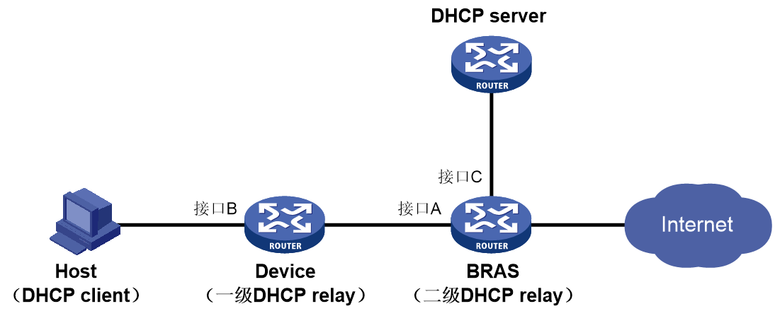
As shown in Figure 32, the host and the BRAS are connected at Layer 3. The device acts as the Level 1 DHCP relay agent. The BRAS acts as the Level 2 DHCP relay agent to obtain user IP addresses from the remote DHCP server.
Figure 32 The BRAS acts as the Level 2 DHCP relay agent on Layer 3 network
|
|
NOTE: In this networking model, only the non-authorization address pool method is supported. For better readability, this chapter separately introduces the authorization address pool method in "IP address acquisition from authorization address pools” and the non-authorization address pool method in "IP address acquisition from non-authorization address pools". |
IP address acquisition from authorization address pools
This IP address acquisition method is not supported.
The DHCP server performs IP address pool selection only based on the gateway address of the Level 1 DHCP relay agent. The BRAS must not authorize any IP address pool, because it is the Level 2 DHCP relay agent.
IP address acquisition from non-authorization address pools
About this task
When you use the non-authorization address pool method (either IP address pool or IP address pool group) for address assignment, you do not need to create any IP address pool on the BRAS. The following configurations are required on the BRAS:
· In IPv4 network:
¡ Perform the following tasks on interface B (user-facing interface) of the Level 1 DHCP relay agent:
- Enable the DHCP relay agent by using the dhcp select relay command.
- Specify the IP address of interface A (user-facing interface) as the DHCP server address by using the dhcp relay server-address command.
¡ Perform the following tasks for the Level 2 DHCP relay agent:
- On interface A (user-facing interface), enable the DHCP relay agent by using the dhcp select relay command.
- On interface A (user-facing interface), specify IP address of the real DHCP server as the DHCP server address by using the dhcp relay server-address command.
- On interface A (user-facing interface) and interface C (DHCP server-facing interface), enable the non-first-hop DHCP relay agent feature by using the dhcp relay non-first-hop enable command. This configuration is required because the BRAS acts as the Level 2 DHCP relay agent that connects the Level 1 DHCP relay agent and the DHCP server.
· In IPv6 network:
¡ Perform the following tasks on interface B (user-facing interface) of the Level 1 DHCP relay agent:
- Enable the DHCPv6 relay agent by using the ipv6 dhcp select relay command.
- Enable support for Option 79 by using the ipv6 dhcp relay client-link-address enable command.
- Specify IPv6 global unicast address of interface A (user-facing interface) as the DHCPv6 server address by using the ipv6 dhcp relay server-address command.
¡ Perform the following tasks on interface A (user-facing interface) of the Level 2 DHCP relay agent:
- Enable the DHCPv6 relay agent by using the ipv6 dhcp select relay command.
- Configure Option 79 as a trusted option by using the ip subscriber trust option79 command.
- Specify IPv6 global unicast address of the real DHCPv6 server as the DHCPv6 server address by using the ipv6 dhcp relay server-address command.
- On receipt of DHCPv6 requests from the Level 1 DHCP relay agent, the BRAS delivers those requests to the access and authentication module for user authentication and authorization by default. Therefore, you do not need to enable the non-first-hop DHCP relay agent feature on interface A or interface C of the BRAS.
Restrictions and guidelines
· In IPv4 network:
¡ You must configure IP addresses for the user-facing interface of the BRAS.
¡ By default, the Level 1 DHCP relay agent uses the preferred IPv4 address of interface B as the DHCP relay gateway address (giaddr). The remote DHCP server performs IP address pool selection based on the DHCP relay gateway address. For example, if interface B has a primary address, the Level 1 DHCP relay agent uses that primary address as the DHCP relay gateway address. If interface B does not have a primary address, the Level 1 DHCP relay agent uses the preferred secondary address as the DHCP relay gateway address.
¡ When you use a device as the remote DHCP server, you must configure an ordinary local address pool on the DHCP server. When you configure the network and gateway-list commands in that address pool, you must not specify the export-route keyword.
· In IPv6 network:
¡ You must configure IPv6 global unicast addresses for the user-facing interface of the BRAS.
¡ By default, the Level 1 DHCP relay agent uses the preferred IPv6 global unicast address of interface B as the DHCP relay gateway address (Link-address). The remote DHCPv6 server performs IPv6 address pool selection based on the DHCP relay gateway address.
¡ When you use a device as the remote DHCPv6 server, you must configure an ordinary local address pool on the DHCPv6 server. When you configure the network command in that address pool, you must not specify the export-route keyword.
(Layer 3 network) The BRAS acts as neither of the DHCP server and the DHCP relay agent
Network configuration
As shown in Figure 33, the host and the BRAS are connected at Layer 3. The BRAS does not act as the DHCP relay agent or DHCP server. The device acts as the DHCP relay agent and a remote DHCP server is used for IP address assignment.
Figure 33 The BRAS acts as neither of the DHCP server and the DHCP relay agent on Layer 3 network
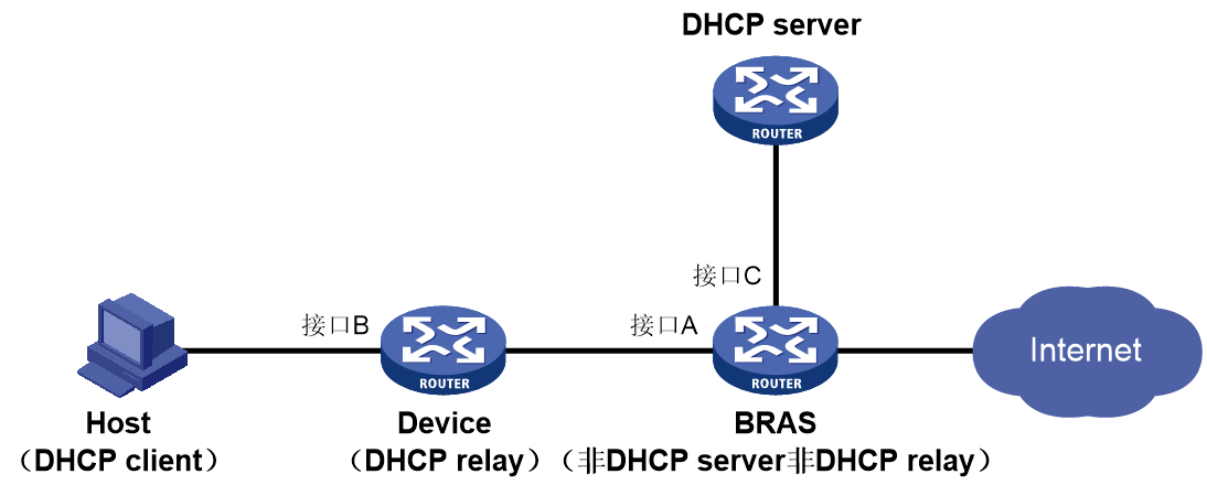
|
|
NOTE: In this networking model, only the non-authorization address pool method is supported. For better readability, this chapter separately introduces the authorization address pool method in "IP address acquisition from authorization address pools” and the non-authorization address pool method in "IP address acquisition from non-authorization address pools". |
IP address acquisition from authorization address pools
This IP address acquisition method is not supported.
The DHCP server performs IP address pool selection only based on the gateway address of the DHCP relay agent. The BRAS must not authorize any IP address pool, because it does not act as the DHCP server or DHCP relay agent.
IP address acquisition from non-authorization address pools
About this task
When you use the non-authorization address pool method (either IP address pool or IP address pool group) for address assignment, you do not need to create any IP address pool on the BRAS.
The DHCP server addresses specified for the DHCP relay agent are IP address of real DHCP servers. When you configure the BRAS, you do not need to configure any authorization address pool in ISP domain view, because the BRAS does not act as the DHCP server or DHCP relay agent. To ensure the BRAS can detect and process the DHCP packets exchanged between the DHCP server and the DHCP relay agent, the following configurations are required:
· In IPv4 network:
¡ Perform the following tasks on interface B (user-facing interface) of the DHCP relay agent:
- Enable the DHCP relay agent by using the dhcp select relay command.
- Specify IP address of the real DHCP server as the DHCP server address by using the dhcp relay server-address command.
¡ Perform the following tasks for the BRAS:
- On interface A (user-facing interface), enable the DHCP relay agent by using the dhcp select relay command.
- On interface A (user-facing interface) and interface C (DHCP server-facing interface), enable the non-first-hop DHCP relay agent feature by using the dhcp relay non-first-hop enable command.
· In IPv6 network:
¡ Perform the following tasks on interface B (user-facing interface) of the DHCP relay agent:
- Enable the DHCPv6 relay agent by using the ipv6 dhcp select relay command.
- Enable support for Option 79 by using the ipv6 dhcp relay client-link-address enable command.
- Specify IPv6 global unicast address of the real DHCPv6 server as the DHCPv6 server address by using the ipv6 dhcp relay server-address command.
¡ Perform the following tasks for the BRAS:
- Enable the DHCPv6 relay agent by using the ipv6 dhcp select relay command.
- Configure Option 79 as a trusted option by using the ip subscriber trust option79 command.
- On interface A (user-facing interface) and interface C (DHCP server-facing interface), enable the non-first-hop DHCP relay agent feature by using the dhcp relay non-first-hop enable command.
Restrictions and guidelines
· In IPv4 network:
¡ You must configure IP addresses for the user-facing interface of the BRAS.
¡ Since the BRAS does not act as the DHCP relay agent, you do not need to use the dhcp relay server-address command to specify DHCP server addresses on interface A.
¡ By default, the DHCP relay agent uses the preferred IPv4 address of interface B as the DHCP relay gateway address (giaddr). The remote DHCP server performs IP address pool selection based on the DHCP relay gateway address. For example, if interface B has a primary address, the DHCP relay agent uses that primary address as the DHCP relay gateway address. If interface B does not have a primary address, the DHCP relay agent uses the preferred secondary address as the DHCP relay gateway address.
¡ When you use a device as the remote DHCP server, you must configure an ordinary local address pool on the DHCP server. When you configure the network and gateway-list commands in that address pool, you must not specify the export-route keyword.
· In IPv6 network:
¡ You must configure IPv6 global unicast addresses for the user-facing interface of the BRAS.
¡ Since the BRAS does not act as the DHCP relay agent, you do not need to use the ipv6 dhcp relay server-address command to specify DHCPv6 server addresses on interface A.
¡ By default, the DHCP relay agent uses the preferred IPv6 global unicast address of interface B as the DHCP relay gateway address (Link-address). The remote DHCPv6 server performs IPv6 address pool selection based on the DHCP relay gateway address.
¡ When you use a device as the remote DHCPv6 server, you must configure an ordinary local address pool on the DHCPv6 server. When you configure the network command in that address pool, you must not specify the export-route keyword.
Differences between the Level 2 DHCP relay agent networking model and the non-DHCP server/relay agent networking model
For brief introduction:
· The networking model involved in “(Layer 3 network) The BRAS acts as the Level 2 DHCP relay agent” is called Level 2 DHCP relay agent.
· The networking model involved in “(Layer 3 network) The BRAS acts as neither of the DHCP server and the DHCP relay agent” is called non-DHCP relay agent/server.
To help users fast understand the key differences between these two scenarios in terms of IP address acquisition configuration, this chapter provides a comparison table as follows:
Table 4 Configuration differences
|
Item |
The BRAS acts as the Level 2 DHCP relay agent |
The BRAS does not act as the DHCP server or DHCP relay agent |
|
Whether the DHCP server address specified for the first-hop DHCP relay agent is real DHCP server address |
No. In fact, the specified DHCP server address is IP address of the user-facing interface on the BRAS. |
Yes |
|
Whether the dhcp select relay or ipv6 dhcp select relay command is required to enable the DHCP relay agent on the user-facing interface of the BRAS |
Required |
Required |
|
Whether the dhcp relay server-address or ipv6 dhcp relay server-address command is required to specify DHCP server addresses on the user-facing interface of the BRAS |
Required. The specified DHCP server addresses must be real DHCP server addresses. |
Not required |
|
In IPv4 network, whether the dhcp relay non-first-hop enable command is required to enable the non-first-hop DHCP relay agent feature on the user-facing interface and the DHCP server-facing interface of the BRAS |
Required |
Required |
|
In IPv6 network, whether the ipv6 dhcp relay non-first-hop enable command is required to enable the non-first-hop DHCP relay agent feature on the user-facing interface and the DHCP server-facing interface of the BRAS |
Not required |
Required |
Basic service key configuration
IPoE roaming configuration
Commands
Use ip subscriber roaming enable [ roam-group roam-group-name ] to enable roaming for IPoE individual users on an interface.
Usage guidelines
About this task
IPoE user roaming allows an IPoE user to stay online when moving among areas covered by multiple wireless networks specified.
Restrictions and guidelines
Make sure the user access interfaces before and after the roaming have IPoE enabled for the same protocol stacks and are configured with the same IPoE authentication method, authentication domain, roaming group, and Option79 trusting state (required only for DHCPv6 users).
Typically, the following packets can trigger roaming: ARP packets, IPv4 packets, and IPv6 packets.
In an IPv4 network:
· To use IPv4 packets to trigger roaming, you must configure the ip subscriber initiator unclassified-ip enable matching-user command on the target interface of roaming.
· To use ARP packets to trigger roaming, you must configure the ip subscriber initiator arp enable and ip subscriber initiator unclassified-ip enable matching-user commands on the target interface of roaming.
As a best practice for roaming in an IPv4 network, configure both unclassified-IPv4 packet initiation and ARP packet initiation.
In an IPv6 network:
· To use IPv6 packets to trigger roaming, you must execute the ip subscriber initiator unclassified-ipv6 enable matching-user command on the target interface of roaming.
· To use NS or NA packets to trigger roaming, you must execute both the ip subscriber initiator nsna enable and ip subscriber initiator unclassified-ipv6 enable matching-user commands on the target interface of roaming.
For roaming in an IPv6 network, as a best practice, use both use IPv6 packets and NS or NA packets to trigger roaming.
For IPoE DHCP user roaming, make sure the following requirements are met:
· For IPoE DHCPv4 users, you must execute the dhcp session-mismatch action roam command on all interfaces for roaming.
· For IPoE DHCPv6 users, you must execute the ipv6 dhcp session-mismatch action roam command on all interfaces for roaming.
· In a DHCP relay agent network, you must execute the dhcp-proxy enable command (default configuration) on the DHCP relay agent interface to enable DHCP server proxy on the relay agent.
For IPoE NDRS users, you must execute the ipv6 dhcp session-mismatch action roam command on all interfaces for roaming.
Examples
# Enable roaming for IPoE individual users and specify roaming group roam1 on subinterface Ten-GigabitEthernet 3/1/1.1.
<Sysname> system-view
[Sysname] interface ten-gigabitethernet 3/1/1.1
[Sysname-Ten-GigabitEthernet3/1/1.1] ip subscriber roaming enable roam-group roam1
Transparent MAC authentication
Commands
Use ip subscriber authentication-method web mac-auth [ basic-service-ipv4 ] [ support-authorized-vpn ] to configure the Web MAC authentication method for IPoE users.
Usage guidelines
About this task
A user needs to enter the username and password only for the first login. Then, the user can access the network without entering the username and password.
Restrictions and guidelines
If Web MAC authentication is configured on an interface, the DHCP user or static user uses common transparent MAC authentication no matter whether a MAC binding server is configured by using the portal apply mac-trigger-server command on the interface.
Examples
# Configure the Web MAC authentication method for IPoE users on Ten-GigabitEthernet 3/1/1.
<Sysname> system-view
[Sysname] interface ten-gigabitethernet 3/1/1
[Sysname-Ten-GigabitEthernet3/1/1] ip subscriber authentication-method web mac-auth
The operation may cut all users on this interface. Continue?[Y/N]:y
Hybrid dual-stack global IPoE static individual sessions
Commands
Syntax 1
· Configure IPv4-stack global IPoE static individual sessions:
ip subscriber session static ip start-ipv4-address [ end-ipv4-address ] [ mac mac-address ] [ domain domain-name ] [ password mac ] [ interface interface-type interface-number [ vlan vlan-id [ second-vlan vlan-id ] ] [ request-online ] ] [ description string ] [ gateway ip ipv4-address ] [ vpn-instance vpn-instance-name ] [ keep-online | support-ds ]
· Configure IPv6-stack global IPoE static individual sessions:
ip subscriber session static ipv6 start-ipv6-address [ end-ipv6-address ] [ delegation-prefix start-ipv6-prefix [ end-ipv6-prefix ] prefix-length ] [ mac mac-address ] [ domain domain-name ] [ password mac ] [ interface interface-type interface-number [ vlan vlan-id [ second-vlan vlan-id ] ] [ request-online ] ] [ description string ] [ gateway ipv6 ipv6-address ] [ vpn-instance vpn-instance-name ] [ keep-online | support-ds ]
Syntax 2
· Configure IPv4-stack global IPoE static individual sessions:
ip subscriber session static ip start-ipv4-address [ end-ipv4-address ] interface-list list-id [ mac mac-address ] [ domain domain-name ] [ password mac ] [ description string ] [ vpn-instance vpn-instance-name ] [ keep-online | support-ds ]
· Configure IPv6-stack global IPoE static individual sessions:
ip subscriber session static ipv6 start-ipv6-address [ end-ipv6-address ] interface-list list-id [ delegation-prefix start-ipv6-prefix [ end-ipv6-prefix ] prefix-length ] [ mac mac-address ] [ domain domain-name ] [ password mac ] [ description string ] [ vpn-instance vpn-instance-name ] [ keep-online | support-ds ]
Usage guidelines
About this task
Specify the support-ds keyword in the command to enable dual stack support.
With this keyword specified, the device allows a global static session and a global dynamic session with the same MAC address and different IP protocols to form a dual-stack session. If the user of a protocol stack passes authentication, the user of the other protocol stack can come online without authentication.
Restrictions and guidelines
· The support-ds keyword takes effect only in Layer 2 access mode.
· Both protocol stacks use the same authentication domain.
· The support-ds keyword and the delegation-prefix keyword cannot be both configured.
Examples
# Configure a hybrid dual-stack global IPoE static session in system view.
<Sysname> system-view
[Sysname] ip subscriber session static ip 192.168.0.2 domain dm1 interface route-aggregation 1 support-ds
Pure dual-stack global IPoE static individual sessions
Commands
Syntax 1
· Configure dual-stack global IPoE static individual sessions:
ip subscriber session static ip start-ipv4-address [ end-ipv4-address ] ipv6 start-ipv6-address [ end-ipv6-address ] [ delegation-prefix start-ipv6-prefix [ end-ipv6-prefix ] prefix-length ] [ mac mac-address ] [ domain domain-name ] [ password mac ] [ interface interface-type interface-number [ vlan vlan-id [ second-vlan vlan-id ] ] [ request-online [ ip | ipv6 ] ] ] [ description string ] [ gateway { ip ipv4-address | ipv6 ipv6-address } * ] [ vpn-instance vpn-instance-name ] [ keep-online ]
Syntax 2
· Configure dual-stack global IPoE static individual sessions:
ip subscriber session static ip start-ipv4-address [ end-ipv4-address ] ipv6 start-ipv6-address [ end-ipv6-address ] interface-list list-id [ delegation-prefix start-ipv6-prefix [ end-ipv6-prefix ] prefix-length ] [ mac mac-address ] [ domain domain-name ] [ password mac ] [ description string ] [ vpn-instance vpn-instance-name ] [ keep-online ]
Usage guidelines
About this task
This type of dual-stack users come online as static users in both the IPv4 protocol stack and IPv6 protocol stack.
· For the IPv4 protocol stack, users can initiate coming online as static users through IPv4 packets or Address Resolution Protocol (ARP) packets.
· For the IPv6 protocol stack, users can initiate coming online as static users through IPv6 packets, Neighbor Solicitation (NS) packets, or Neighbor Advertisement (NA) packets.
Restrictions and guidelines
· In a global static session, the IPv4 addresses and IPv6 addresses specified for dual-stack users must correspond in one-one mode.
· IPv4 addresses are in dotted decimal notation, and IPv6 addresses are in hexadecimal notation. For example, IPv4 addresses 1.1.1.1 through 1.1.1.100 can correspond to IPv6 addresses 1::1 through 1::64 but cannot correspond to IPv6 addresses 1::1 to 1::100.
Examples
# In system view, configure a dual-stack global static IPoE session.
<Sysname> system-view
[Sysname] ip subscriber session static ip 1.1.1.1 1.1.1.100 ipv6 1::1 1::64 domain dm1 interface route-aggregation 1
BRAS-level IPoE 802.1X authentication
Commands
Use ip subscriber authentication-method dot1x [ high-priority ] to configure the IPoE 802.1X authentication method.
Usage guidelines
About this task
IPoE 802.1X authentication supports DHCP users, IPv6 ND RS users, and static users.
When both 802.1X authentication and Web authentication are configured on an interface, a user can use only one of them to perform authentication and come online at a time. 802.1X authentication takes priority over Web authentication.
Restrictions and guidelines
When you configure 802.1X authentication, follow these restrictions and guidelines:
· You can configure 802.1X authentication on an interface only when the interface operates in Layer 2 IPoE access mode.
· On an interface, 802.1X authentication is mutually exclusive with Layer 3 IPoE access mode, IPoE interface-leased users, IPoE subnet-leased users, and IPoE L2VPN-leased users.
Examples
# Configure the 802.1X authentication method for IPoE users on Ten-GigabitEthernet 3/1/1.
<Sysname> system-view
[Sysname] interface ten-gigabitethernet 3/1/1
[Sysname-Ten-GigabitEthernet3/1/1] ip subscriber authentication-method dot1x
The operation may cut all users on this interface. Continue?[Y/N]:y
NAS-Port-ID three-/four-dimensional interfaces
Commands
Use access-user four-dimension-mode enable to configure the device to use four-dimensional interfaces to communicate with AAA servers.
Usage guidelines
About this task
By default, in a unified network, when the device communicates with AAA servers, the device uses three-dimensional interface numbers without the chassis information in interface information, for example, NAS-Port-ID. On an IRF fabric, when you need to specify the access IRF member device of a user on the AAA server, use this command to configure the device to use four-dimensional interfaces to communicate with AAA servers.
Restrictions and guidelines
· This command takes effect only on users coming online after this command is executed.
· This feature takes effect only on users coming online through physical interfaces, and does not take effect on users coming online through global interfaces such as Layer 3 aggregate interfaces.
Examples
# Configure the device to use four-dimensional interfaces to communicate with AAA servers.
<Sysname> system-view
[Sysname] access-user four-dimension-mode enable
Configuring Web authentication fail-permit
Commands
Use ip subscriber pre-auth track track-entry-number fail-permit user-group group-name to associate a fail-permit user group with a track entry.
Usage guidelines
About this task
With this feature configured, when the device detects that the Web authentication server or AAA server is unreachable, the device allows users to access network resources without Web authentication. This process is called Web authentication fail-permit. You can implement Web authentication fail-permit by associating a fail-permit user group with a track entry.
By default, the Web authentication users that come online in the preauthentication domain belong to the user group authorized by AAA or authorized in the ISP domain when the users come online. After a fail-permit user group is associated with a track entry, the following rules apply:
· When the status of the track entry becomes Negative, the BRAS device moves all online users in the current preauthentication domain from the authorized user group to the fail-permit user group. Then, the users can access network resources according to the privilege of the fail-permit user group.
· When the status of the track entry becomes Positive, the BRAS device will move all online users in the current preauthentication domain back to the authorized user group. Then, the users can access network resources only after passing Web authentication.
Restrictions and guidelines
To monitor the status of multiple servers, you can configure the tracked object list.
This feature takes effect only on users in the preauthentication domain.
If you execute the ip subscriber pre-auth track track-entry-number fail-permit user-group group-name command multiple times, the most recent configuration takes effect.
Examples
· Configure an NQA operation with administrator name admin and operation tag test1.
<Sysname> system-view
# Create an NQA operation with administrator name admin and operation tag test1.
[Sysname] nqa entry admin test1
# Configure the NQA operation type as ICMP echo.
[Sysname-nqa-admin-test1] type icmp-echo
# Specify 4.4.4.5 as the destination IP address.
[Sysname-nqa-admin-test1-icmp-echo] destination ip 4.4.4.5
# Configure the operation to repeat every 100 milliseconds.
[Sysname-nqa-admin-test1-icmp-echo] frequency 100
# Create reaction entry 1. If the number of consecutive probe failures reaches 5, collaboration is triggered.
[Sysname-nqa-admin-test1-icmp-echo] reaction 1 checked-element probe-fail threshold-type consecutive 5 action-type trigger-only
[Sysname-nqa-admin-test1-icmp-echo] quit
# Start the ICMP echo operation.
[Sysname] nqa schedule admin test1 start-time now lifetime forever
· Configure an NQA operation with administrator name admin and operation tag test2.
# Create an NQA operation with administrator name admin and operation tag test2.
[Sysname] nqa entry admin test2
# Configure the NQA operation type as ICMP echo.
[Sysname-nqa-admin-test2] type icmp-echo
# Specify 4.4.4.6 as the destination IP address.
[Sysname-nqa-admin-test2-icmp-echo] destination ip 4.4.4.6
# Configure the operation to repeat every 100 milliseconds.
[Sysname-nqa-admin-test2-icmp-echo] frequency 100
# Create reaction entry 2. If the number of consecutive probe failures reaches 5, collaboration is triggered.
[Sysname-nqa-admin-test2-icmp-echo] reaction 2 checked-element probe-fail threshold-type consecutive 5 action-type trigger-only
[Sysname-nqa-admin-test2-icmp-echo] quit
# Start the ICMP echo operation.
[Sysname] nqa schedule admin test2 start-time now lifetime forever
· Create track entries.
# Create track entry 1, and associate it with reaction entry 1 of the NQA operation with administrator name admin and operation tag test1.
[Sysname] track 1 nqa entry admin test1 reaction 1
# Create track entry 2, and associate it with reaction entry 2 of the NQA operation with administrator name admin and operation tag test2.
[Sysname] track 2 nqa entry admin test2 reaction 2
· Configure a Boolean tracked list.
# Create Boolean AND list 100 and enter its view.
[Sysname] track 100 list boolean and
# Add track entries 1 and 2 as tracked objects to the list.
[Sysname-track-100] object 1
[Sysname-track-100] object 2
· Create a local user group named flee.
[BRAS] user-group flee
New user group added.
[BRAS-ugroup-flee] quit
· Associate fail-permit user group flee with Boolean tracked list 100 on Ten-GigabitEthernet 3/1/1.
[Sysname] interface ten-gigabitethernet 3/1/1
[Sysname-Ten-GigabitEthernet3/1/1] ip subscriber pre-auth track 100 fail-permit user-group flee
AAA fail-permit and recovery
Commands
· Use authen-radius-unavailable online domain new-isp-name to specify a critical domain for an ISP domain to accommodate users that access the ISP domain when all RADIUS servers are unavailable.
· Use authen-radius-recover { offline | online domain new-isp-name } to specify the action to take on users in the critical domain when a RADIUS server in the users' original authentication domain becomes available.
· Use radius-server authen-state-check interval interval to set the interval at which the device detects the status of RADIUS authentication servers.
Usage guidelines
About this task
This feature is used to resolve the issue that users that use a RADIUS scheme cannot come online when all RADIUS servers in the RADIUS scheme are unavailable. The feature contains the following settings in a user authentication domain:
In the user authentication domain, specify a critical domain (also known as fail-permit domain) to accommodate users that access the authentication domain when all RADIUS servers are unavailable. The users can come online in the critical domain without being authenticated when all RADIUS servers are unavailable.
In the user authentication domain, specify an action to take on users that have been assigned to the critical domain when a RADIUS server for the authentication domain becomes available.
· To perform authentication, authorization, and accounting for the users, log off the users.
· To assign the users back to the authentication domain, allow the users to stay online and specify the authentication domain as the recovery domain. The device does not perform authentication, authorization, or accounting for the users after the users are assigned to the recovery domain. The users can obtain the effective authorization attributes in the recovery domain. To specify the effective authorization attributes, use the dynamic-authorization effective-attribute command.
For the device to obtain the status of RADIUS authentication servers in time, it detects the status of the RADIUS authentication servers in each RADIUS scheme at intervals. In addition, the device notifies access modules to remove users that use a RADIUS scheme from the critical domain when that RADIUS scheme has reachable RADIUS servers.
Restrictions and guidelines
This feature takes effect only on IPoE and PPPoE users.
The action to take on users in the critical domain when a RADIUS server in the users' original authentication domain becomes available is online for fail-permit recovery in the IPoE Web preauthentication domain and offline for fail-permit recovery in the Web postauthentication domain.
When you specify a critical domain for an ISP domain, follow these restrictions and guidelines:
· If non-none authentication, authorization, or accounting methods are configured in the critical domain for an ISP domain, the non-none authentication or authorization methods cannot take effect on users. However, the non-none accounting methods in the critical domain can take effect on users.
· If an ISP domain has been specified as a critical domain, do not specify a critical domain for that ISP domain. If you do so, the critical domain specified for that ISP domain cannot take effect. If a critical domain has been specified for an ISP domain, do not specify that ISP domain as a critical domain. If you do so, that ISP domain cannot act as a critical domain.
· To delete an ISP domain that has been specified as the critical domain, you must first use undo authen-radius-unavailable online domain command to remove the critical domain setting from the ISP domain.
When you specify a recovery domain for an ISP domain, follow these restrictions and guidelines:
· If the none method is configured as the backup authentication method in the original authentication domain before the users are assigned to the critical domain, the users still can be assigned to the recovery domain when a RADIUS server becomes available.
· As a best practice to accurately identify whether a RADIUS authentication server is available and the recovery configuration can take effect in time, configure RADIUS server status detection.
· If you do not specify the original authentication domain as the recovery domain, users in the critical domain are assigned to the recovery domain after a RADIUS server becomes available. However, the device does not perform authentication, authorization, or accounting for the users.
· To delete an ISP domain that has been specified as the recovery domain, you must first use the undo authen-radius-recover command to remove the recovery domain setting from the ISP domain.
When you set the interval at which the device detects the status of RADIUS authentication servers, follow these restrictions and guidelines:
· A too short detection interval consumes too many system resources for access services. A too long detection interval cannot detect server status changes in time.
· As a best practice, consider the processing efficiency for access services and the accuracy for fail-permit and recovery when a large number of users come online in a short time.
Examples
# In ISP domain test, specify the critical domain as dm1, and log off users in the critical domain when a RADIUS server in the users' original authentication domain becomes available.
<Sysname> system-view
[Sysname] domain name test
[Sysname-isp-test] authen-radius-unavailable online domain dm1
[Sysname-isp-test] authen-radius-recover offline
[Sysname-isp-test] quit
# Configure the device to detect the status of RADIUS authentication servers at intervals of 2 minutes.
[Sysname] radius-server authen-state-check interval 2
Enabling the DHCPv6 relay agent to support Option 79
Commands
Use ipv6 dhcp relay client-link-address enable to enable the DHCPv6 relay agent to support Option 79.
Usage guidelines
About this tasks
If DHCPv6 relay agents exist in the network, the DHCPv6 server needs the MAC address of a DHCPv6 client for authentication, IPv6 address assignment, prefix assignment, or assignment of other network settings. To meet the requirement, enable the DHCPv6 relay agent that the client first passes to support Option 79. This feature allows the DHCPv6 relay agent to learn the MAC address in the client request. When the relay agent generates a Relay-Forward packet for the request, it fills the MAC address of the client in Option 79. The Relay-Forward packet is then forwarded to the DHCPv6 server.
Restrictions and guidelines
You can configure this feature on cross-Layer 3 networks. To ensure that users need to pass authentication only once in the IPv4/IPv6 dual-stack scenario, perform the following tasks:
· Enable the DHCPv6 relay agent to support Option 79 by using the ipv6 dhcp relay client-link-address enable command.
· Configure Option 79 as a trusted option on the BRAS device by using the ip subscriber trust option79 command.
Examples
# On Ten-GigabitEthernet 3/1/1, enable the relay agent to support Option 79.
<Sysname> system-view
[Sysname] interface ten-gigabitethernet 3/1/1
[Sysname-Ten-GigabitEthernet3/1/1] ipv6 dhcp relay client-link-address enable
Configuring trusted DHCP options for DHCP users
Commands
Use ip subscriber trust { option12 | option60 | option77 | option82 | option16 | option17 | option18 | option37 | option79 } to configure a trusted DHCP option for DHCP users.
Usage guidelines
About this tasks
By default, only Option 79 is trusted and other DHCP options are not trusted. To use an untrusted DHCP option, first perform this task to configure the option as a trusted option.
Restrictions and guidelines
You can configure this feature on cross-Layer 3 networks. To ensure that users need to pass authentication only once in the IPv4/IPv6 dual-stack scenario, perform the following tasks:
· Enable the DHCPv6 relay agent to support Option 79 by using the ipv6 dhcp relay client-link-address enable command.
· Configure Option 79 as a trusted option on the BRAS device by using the ip subscriber trust option79 command.
Examples
# On Ten-GigabitEthernet 3/1/1, configure Option 79 as a trusted option.
<Sysname> system-view
[Sysname] interface ten-gigabitethernet 3/1/1
[Sysname-Ten-GigabitEthernet3/1/1] ip subscriber trust option79
Enabling the DHCP server to return a DHCP-NAK message upon client notions of incorrect IP addresses
Commands
Use dhcp server request-ip-address check to enable the DHCP server to return a DHCP-NAK message if the client notions of their IP addresses are incorrect.
Usage guidelines
About this task
A DHCP client can send a DHCP-REQUEST message directly or upon receiving a DHCP-OFFER message. Upon receiving the request, the DHCP server will check if the client notion of its IP address is correct. If the requested IP address is different from the allocated one or has no matching lease record, the DHCP server remains silent by default. After the allocated IP address lease for the client expires, the DHCP server will make response to request from the client.
This feature enables the DHCP server to return DHCP-NAK messages if the client notions of their IP addresses are incorrect. After receiving the DHCP-NAK message, the DHCP client will request an IP address again.
Recommended configurations
Configure this feature for all of the DHCP servers on the BRAS networking model.
Examples
# Enable the DHCP server to return a DHCP-NAK message if the client notions of their IP addresses are incorrect.
<Sysname> system-view
[Sysname] dhcp server request-ip-address check
Configuring the captive-bypass feature
Commands
Use ip subscriber captive-bypass enable [ android | ios ] [ optimize ] to enable the captive-bypass feature.
· android: Specifies Android users.
· ios: Specifies iOS users.
· optimize: Enables captive-bypass optimization.
Application scenarios
This feature is applicable in scenarios where you configure the device to push the Web authentication page only when a user in the network accesses the Internet by using a browser.
Usage guidelines
About this task
By default, the device automatically pushes the Web authentication page to the iOS devices and some Android devices when they are connected to the network with IPoE Web authentication enabled. With the captive-bypass feature enabled, the device does not automatically push the Web authentication page to iOS devices and some Android devices when they are connected to the network. The device pushes the Web authentication page only when the user accesses the Internet by using a browser.
Restrictions and guidelines
The captive-bypass optimization feature takes effect only on iOS users and does not take effect on Android users.
With the captive-bypass optimization feature enabled, when an iOS user uses a browser to access the Internet, the Web authentication page automatically opens. When the user does not perform authentication and presses the home button to return to the home screen, the Wi-Fi connection is not disconnected.
When you execute this command without specifying any keyword, this command enables the captive-bypass feature for both Android users and iOS users. If you specify only the optimize keyword, this command enables the captive-bypass feature for Android users and the captive-bypass optimization feature for iOS users.
Examples
# Enable the captive-bypass feature.
<Sysname> system-view
[Sysname] interface ten-gigabitethernet 3/1/1
[Sysname-Ten-GigabitEthernet3/1/1] ip subscriber captive-bypass enable
# Enable the captive-bypass optimization feature for iOS users.
<Sysname> system-view
[Sysname] interface ten-gigabitethernet 3/1/1
[Sysname-Ten-GigabitEthernet3/1/1] ip subscriber captive-bypass enable ios optimize
# Enable the captive-bypass feature for Android users.
<Sysname> system-view
[Sysname] interface ten-gigabitethernet 3/1/1
[Sysname-Ten-GigabitEthernet3/1/1] ip subscriber captive-bypass enable android
RADIUS proxy
RADIUS proxy feature configuration
Commands
Use radius-proxy to enable the RADIUS proxy feature and enter RADIUS proxy view.
Usage guidelines
About this task
Use this command to enable the RADIUS proxy feature on the access device if both of the following conditions exist:
· 802.1X authentication is configured for wireless clients to access the network and IPoE authentication is configured for all clients to access the network.
· The access device enabled with IPoE authentication does not support 802.1X authentication for wireless clients. IPoE authentication and 802.1X authentication are enabled on different devices.
This command enables the access device to act as a RADIUS proxy to participate in the RADIUS authentication, authorization, and accounting process of wireless 802.1X clients. The device performs RADIUS proxy as follows:
· Listens for authentication request packets from the specified RADIUS clients and forwards the request packets to the corresponding RADIUS servers of the RADIUS clients.
· Upon receiving authentication response packets from the RADIUS servers, the RADIUS proxy forwards the response packets to the RADIUS clients. In addition, the device generates local proxy user entries for authenticated 802.1X clients to record their username, IP address, MAC address, RADIUS client, and authorization information.
· Upon receiving accounting request packets from the RADIUS clients, the RADIUS proxy responds to them directly without forwarding the request packets to the RADIUS servers.
Restrictions and guidelines
· Use the RADIUS proxy feature only in scenarios where both IPoE authentication and wireless 802.1X authentication are configured for clients to access the network. As a best practice to ensure successful accounting for users that do not need a RADIUS proxy, do not enable the RADIUS proxy feature in any other scenarios.
·By default, the RADIUS proxy feature and the RADIUS session-control feature use UDP port 1812 to listen for authentication request packets and session-control packets, respectively. If you use both the RADIUS proxy and RADIUS session-control features, make sure the two features use different ports to listen for packets.
· Disabling the RADIUS proxy feature deletes all settings from RADIUS proxy view.
Examples
# Enable the RADIUS proxy feature and enter RADIUS proxy view.
<Sysname> system-view
[Sysname] radius-proxy
[Sysname-radius-proxy]
Specifying a RADIUS client
Commands
Use client { ip ipv4-address | ipv6 ipv6-address } [ vpn-instance vpn-instance-name ] radius-scheme radius-scheme-name [ key { cipher | simple } string ] [ authentication-port authentication-port-num ] [ accounting-port accounting-port-num ] [ dae-server-port dae-server-port-num ] to specify a RADIUS client.
Usage guidelines
About this task
With the RADIUS proxy feature, the device listens for and processes authentication and accounting request packets from the specified RADIUS clients.
· When the device receives an authentication request packet from a RADIUS client, it first matches the source IP address and VPN instance of the packet with local RADIUS client settings.
¡ If no matching RADIUS client is found or no RADIUS client has been specified on the device , the device discards the packet.
¡ If a matching RADIUS client is found, the device uses the shared key of the matching RADIUS client to validate the packet. If the packet fails the validation, the device discards the packet. If the packet passes the validation, the device forwards the packet to the RADIUS server in the RADIUS scheme specified by using the radius-scheme keyword. Then, the device listens for the response to the request packet and forwards the response to the RADIUS client.
· When the device receives an accounting request packet from a RADIUS client, it first validates the packet in the same way the authentication request packet was validated. If the packet passes the validation, the device responds to the request with accounting success. If the packet fails the validation, the device responds to the request with accounting failure. Unlike authentication, the device does not forward the accounting request packet to the RADIUS server after it passes the validation.
Restrictions and guidelines
· Make sure a RADIUS client uses the same RADIUS scheme for wireless client authentication, authorization, and accounting. This configuration ensures that the RADIUS proxy can listen for the stop-accounting request packets of wireless online users from the RADIUS client. As a result, the RADIUS proxy can clear local proxy user entries in time to release memory space.
· For a RADIUS client, make sure the authentication and accounting ports configured on the RADIUS proxy are the same as the destination UDP ports of authentication and accounting packets sent by the RADIUS client, respectively. In addition, the authentication and accounting ports must be different.
· If you specify a RADIUS client that has the same IP address and VPN instance as an existing RADIUS client, the most recent configuration overwrites the previous configuration.
· Make sure the RADIUS proxy and a RADIUS client use the same port to forward DAE packets. On the RADIUS proxy, the port is the destination UDP port that the RADIUS proxy uses to forward DAE packets to the RADIUS client (acts as a DAS). On the RADIUS client, the port is the RADIUS DAS port configured by using the port command in RADIUS DAS view.
Examples
# Specify the RADIUS client at 3.3.3.3 for the RADIUS proxy and set the shared key to 123456 in plaintext form for secure RADIUS communication with the RADIUS client. The RADIUS proxy uses the RADIUS servers in RADIUS scheme rs1 for the users from the RADIUS client.
<Sysname> system-view
[Sysname] radius-proxy
[Sysname-radius-proxy] client ip 3.3.3.3 radius-scheme rs1 key simple 123456
PPPoE agency
PPPoE agency configuration
Commands
Use pppoe-agency bind virtual-template number pppoe-agency-group pppoe-agency-group-name to enable the PPPoE agency on an interface and bind the interface to a PPPoE agency group.
Usage guidelines
About this task
With this feature configured, when a campus BRAS user initiates the agency process, the campus BRAS will select one interface that matches the PPPoE agency group name carried in COA messages from the interfaces with the pppoe-agency bind command executed (PPPoE agency interfaces, called agency interface for short). Then, the campus BRAS will use the selected interface to simulate a PPPoE client and initiate PPPoE dialup for network access to the PPPoE server of the corresponding ISP.
If the PPPoE agency group name carried in the COA messages authorized to a user matches the pppoe-agency-group-name argument value configured on multiple interfaces, the device will select the interface with the least online PPPoE agency users to simulate a PPPoE client for the user to perform PPPoE dialup. If multiple interfaces meet the requirements, the device randomly selects one from them.
Restrictions and guidelines
· When the PPPoE agency is enabled on an interface, the VT interface bound to the interface must exist.
· When online PPPoE agency users exist on an interface, you cannot directly use the undo pppoe-agency bind command to disable the PPPoE agency on the interface. To do that, first log out all online PPPoE agency users on the interface, and then execute the undo pppoe-agency bind command.
· If an interface has the PPPoE agency enabled and is bound to a VT interface, you cannot directly use this command to bind the interface to a new VT interface. To do that, first disable the PPPoE agency on the interface, and then re-enable the PPPoE agency on the interface and bind it to a new VT interface.
· If both the PPPoE client and PPPoE agency are enabled on an interface, the PPPoE client does not take effect.
· When the device is configured to operate in user plane mode by using the work-mode user-plane command, you cannot enable the PPPoE agency on any interface of the device.
· On an interface, the pppoe-agency bind command and the pppoe-server bind command are mutually exclusive.
Examples
# Enable the PPPoE agency on Ten-GigabitEthernet 3/1/1, and bind Ten-GigabitEthernet 3/1/1 to VT interface 1 and PPPoE agency group 1.
<Sysname> system-view
[Sysname] interface ten-gigabitethernet 3/1/1
[Sysname-Ten-GigabitEthernet3/1/1] pppoe-agency bind virtual-template 1 pppoe-agency-group 1
PPPoE agency forwarding policy configuration
Commands
Use pppoe-agency forward { ipv4 | ipv6 } acl { acl-number | name acl-name } to configure a PPPoE agency forwarding policy.
Usage guidelines
About this task
If a campus BRAS receives the external network traffic of a PPPoE agency user before the campus BRAS initiates PPPoE dialup for network access to the PPPoE server of the corresponding ISP, the campus BRAS directly drops the traffic.
In the current software version, only IPoE individual users and PPPoE users support the PPPoE agency feature. Among these users, IPoE Web individual users support the PPPoE agency feature only in the postauthentication phase, and do not support the PPPoE agency feature in the preauthentication phase.
Restrictions and guidelines
When specifying an ACL, follow these restrictions and guidelines:
· Do not specify the user-group keyword in any ACL rule. If you do that, the PPPoE agency function based on the ACL is not available.
· If the specified ACL does not exist or does not have any rules, all traffic is external network traffic and must be forwarded through the PPPoE agency.
· In the specified ACL, the following rules apply:
¡ If a rule has the vpn-instance keyword specified, the rule takes effect only on users in the specified VPN instance, and user traffic matching the ACL rule in the specified VPN instance is considered as internal network traffic and directly forwarded.
¡ If a rule does not have the vpn-instance keyword specified, the rule takes effect only on all users (including users in VPN instances). When user traffic is compared with the ACL rule, its VPN attributes are ignored. User traffic matching the ACL rule is considered as internal network traffic and directly forwarded.
Examples
# Configure user group group1 to directly forward traffic matching IPv4 ACL 3000 and forward non-matching traffic through the PPPoE agency or drop the non-matching traffic.
<Sysname> system-view
[Sysname] user-group group1
[Sysname-ugroup-group1] pppoe-agency forward ipv4 acl 3000
ITA configuration
Specify the traffic level for accounting
Commands
Use accounting-level level { { ipv4 | ipv6 } | car { inbound cir committed-information-rate [ pir peak-information-rate ] | outbound cir committed-information-rate [ pir peak-information-rate ] } * } * to specify the traffic level for accounting.
Usage guidelines
About this task
By default, no traffic levels are specified for accounting.
By defining different traffic levels based on the destination addresses of users' traffic, you can use ITA to separate the traffic accounting statistics of different levels for each user.
Restrictions and guidelines
· You can execute this command multiple times to specify different traffic levels for accounting and specify different traffic monitoring parameters for different traffic levels. If you specify only the traffic monitoring parameters for a traffic level but do not specify the ipv4 or ipv6 keyword, the system does not perform accounting for traffic of the level.
· If you do not specify the level keyword when executing the undo accounting-level command, the command deletes all the specified traffic levels for the ITA policy.
· If the IP type specified by using this command is inconsistent from the actual IP type of ITA traffic, the system performs accounting on ITA traffic based on the specified IP type.
· If you do not specify the ipv4 or ipv6 keyword, the system does not perform accounting on ITA traffic.
Examples
# In ITA policy ita1, specify the traffic level 2 and 4 for IPv4 and IPv6 traffic, respectively.
<Sysname> system-view
[Sysname] ita policy ita1
[Sysname-ita-policy-ita1] accounting-level 2 ipv4
[Sysname-ita-policy-ita1] accounting-level 4 ipv6
Specify the accounting method for the ITA service
Commands
Use accounting-method { none | radius-scheme radius-scheme-name [ none ] } to specify the accounting method for an ITA policy.
Usage guidelines
About this task
By default, an ITA policy uses the none accounting scheme.
You can perform this task to specify an accounting scheme only for ITA traffic.
Restrictions and guidelines
You can specify a backup accounting method for the system to use when the current accounting method fails. For example, the radius-scheme radius-scheme-name none configuration indicates using the RADIUS scheme for accounting and using none scheme if the specified RADIUS scheme is invalid. Remote accounting is invalid if the specified accounting scheme does not exist, accounting packet sending fails, or the server is not responding. Local accounting is invalid if the corresponding local user configuration is not found.
Examples
# Specify accounting scheme radius1 for ITA policy ita1.
<Sysname> system-view
[Sysname] ita policy ita1
[Sysname-ita-policy-ita1] accounting-method radius-scheme radius1
Separate ITA traffic from overall accounting traffic
Commands
Use traffic-separate enable [ level level&<1-8> ] to exclude the amount of ITA traffic from the overall traffic statistics that are sent to the accounting server.
Usage guidelines
By default, the amount of ITA traffic is included in the overall traffic statistics that are sent to the accounting server.
After you separate ITA traffic from the overall accounting traffic, the total accounting traffic reported by a BRAS device to the accounting server does not include ITA traffic of the specified level.
Examples
# In ITA policy ita1, exclude the amount of ITA traffic of level 1 from the overall traffic statistics that sent to the accounting server.
<Sysname> system-view
[Sysname] ita policy ita1
[Sysname-ita-policy-ita1] traffic-separate enable level 1
Configure accounting merge
Commands
Use accounting-merge enable to enable accounting merge feature.
Usage guidelines
By default, the accounting merge feature is disabled.
When accounting merge is enabled, the device merges accounting statistics for the ITA traffic of all levels in the ITA policy. It reports the traffic as the lowest level of the policy to the accounting server.
Examples
# Enable the accounting merge feature for ITA policy ita1.
<Sysname> system-view
[Sysname] ita policy ita1
[Sysname-ita-policy-ita1] accounting-merge enable
Configure access control for users that have used up their ITA data quotas
Commands
Use traffic-quota-out { offline | online } [ no-accounting-update ] to configure access control for users that have used up their ITA data quotas.
Usage guidelines
About this task
By default, after a user uses up its ITA data quota, the device sends accounting update requests to the server to obtain a new data quota. If the accounting response does not carry any new data quota, the user cannot access the authorized IP subnets.
Recommended configuration
If the server does not support issuing traffic quotas to online users multiple times, specify the no-accounting-update keyword when you execute this command as a best practice to reduce the burden on the server.
Examples
# In ITA policy ita1, prohibit users from accessing the authorized IP subnets after their ITA data quotas are used up.
<Sysname> system-view
[Sysname] ita policy ita1
[Sysname-ita-policy-ita1] traffic-quota-out offline
Configuring the traffic permission action
Commands
Use the free account command to permit packets, without rate limiting and accounting.
Usage guidelines
About this task
By default, the BRAS device processes packets as follows:
· For packets matching a QoS policy:
¡ The filter permit and filter deny commands have higher priority than the free account command.
¡ The free account command does not rate limit or count packets.
For example, if you execute both the filter deny and free account commands in traffic behavior web_deny, the device drops matching packets and does not count the dropped packets.
<Sysname> system-view
[Sysname] traffic behavior web_deny
[Sysname-behavior-web_deny] filter deny
[Sysname-behavior-web_deny] free account
· By default, the device drops packets from users that are not online. To permit matching packets without rate limiting and accounting, use the free account command.
For example, if you execute the free account command in traffic behavior web_permit, the BRAS device permits matching packets and does not rate limit or count the permitted packets.
<Sysname> system-view
[Sysname] traffic behavior web_permit
[Sysname-behavior-web_permit] free account
· The BRAS device processes packets from online users according to the configured QoS policy. To permit matching packets without rate limiting and accounting, execute both the filter permit and free account commands in a traffic behavior.
For example, if you execute both the filter permit and free account commands in traffic behavior web_permit, the device permits matching packets and does not rate limit or count the permitted packets.
<Sysname> system-view
[Sysname] traffic behavior web_permit
[Sysname-behavior-web_permit] filter permit
[Sysname-behavior-web_permit] free account
Restrictions and guidelines
For a QoS policy that matches internal traffic in an IPoE network:
· If you do not need to count internal traffic, use the free account command.
· If you need to count internal traffic, do not use the free account command.
Configuration example
In traffic behavior web_permit, permit matching packets without rate limiting and accounting.
<Sysname> system-view
[Sysname] traffic behavior web_permit
[Sysname-behavior-web_permit] free account
Attack detection key settings
To ensure network security, network administrators must perform required attack detection configuration as described in this section.
Source MAC-based ARP attack detection
Commands
· Use arp source-mac { filter | monitor } to enable the source MAC-based ARP attack detection feature and specify the filter handling method.
· Use arp source-mac check-interval interval to set the check interval for source MAC-based ARP attack detection.
· Use arp source-mac threshold threshold-value to set the threshold for source MAC-based ARP attack detection.
· Use arp source-mac aging-time time to set the aging time for source MAC-based ARP attack detection entries.
· Use arp source-mac exclude-mac mac-address&<1-n> to exclude specific MAC addresses from source MAC-based ARP attack detection.
Usage guidelines
Application scenarios
When there are abnormal situations in the network, such as loop, BRAS devices need to process a large number of received ARP request packets, which consumes CPU resources and affects the CPU processing capability for other services.
To resolve the issue, configure the source MAC-based ARP attack detection feature.
About this task
This feature checks the number of ARP packets delivered to the CPU. If the number of packets from the same MAC address within the check interval exceeds the threshold, the device generates an ARP attack detection entry for the MAC address.
The device handles the attack by using either of the following methods before the ARP attack entry ages out:
· Filter—Generates log messages and filters out subsequent ARP packets from the MAC address.
· Monitor—Only generates log messages.
For a MAC address that has been added to the ARP attack detection table with a fixed source MAC address, if the number of ARP packets discarded within the aging time is greater than or equal to the specified value, the device resets the aging time of the entry. If the number is less than the specified value, the device restores the MAC address as a normal MAC address.
Restrictions and guidelines
As a best practice, enable this feature after the network is connected correctly to prevent the device from regarding the gratuitous ARP packets sent by the peer as attack packets when the interface is up.
In a Layer 3 network, a gateway (such as a DHCP relay agent) might exist before the BRAS device. The ARP packets received on the interface connected to the gateway might have the same source MAC address. To prevent the BRAS device from intercepting normal ARP packets as attack packets and affecting user access, you can exclude the MAC address of the gateway from source MAC-based ARP attack detection.
Examples
The parameter values in this example are recommended configurations for most networks. You can adjust them according to actual conditions.
# Enable source MAC-based ARP attack detection and specify the filter handling method.
<Sysname> system-view
[Sysname] arp source-mac filter
# Set the check interval to 5 seconds for source MAC-based ARP attack detection.
[Sysname] arp source-mac check-interval 5
# Set the threshold to 30 for source MAC-based ARP attack detection.
[Sysname] arp source-mac threshold 30
# Set the aging time to 300 seconds for source MAC-based ARP attack detection entries.
[Sysname] arp source-mac aging-time 300
# Exclude MAC address 001e-1200-0213 from source MAC-based ARP attack detection.
[Sysname] arp source-mac exclude-mac 001e-1200-0213
Source MAC-based ND attack detection
Commands
· Use ipv6 nd source-mac { filter | monitor } to enable the source MAC-based ND attack detection feature and specify the filter handling method.
· Use ipv6 nd source-mac aging-time time to set the aging time for source MAC-based ND attack detection entries.
· Use ipv6 nd source-mac check-interval interval to set the check interval for source MAC-based ND attack detection.
· Use ipv6 nd source-mac threshold threshold-value to set the threshold for source MAC-based ND attack detection.
· Use ipv6 nd source-mac exclude-mac mac-address&<1-n> to exclude specific MAC addresses from source MAC-based ND attack detection.
Usage guidelines
Application scenarios
When there are abnormal situations in the network, such as loop, BRAS devices need to process a large number of received NS packets, which consumes CPU resources and affects the CPU processing capability for other services.
To resolve the issue, configure the source MAC-based ND attack detection feature.
About this task
This feature checks the number of ND packets delivered to the CPU. If the number of packets from the same MAC address within the check interval exceeds the threshold, the device generates an ND attack detection entry for the MAC address.
The device handles the attack by using either of the following methods before the ND attack entry ages out:
· Filter—Generates log messages and filters out subsequent ND packets from the MAC address.
· Monitor—Only generates log messages.
For a MAC address that has been added to the ND attack detection table with a fixed source MAC address, if the number of ND packets discarded within the aging time is greater than or equal to the specified value, the device resets the aging time of the entry. If the number is less than the specified value, the device deletes the entry and restores MAC address a normal MAC address.
Restrictions and guidelines
As a best practice, enable this feature on the gateway.
As a best practice, enable this feature after the network is connected correctly to prevent the device from regarding the NS packets sent by the peer as attack packets when the interface is up.
In a Layer 3 network, a gateway (such as a DHCP relay agent) might exist before the BRAS device. The ND packets received on the interface connected to the gateway might have the same source MAC address. To prevent the BRAS device from intercepting normal ND packets as attack packets and affecting user access, you can exclude the MAC address of the gateway from source MAC-based ND attack detection.
Examples
The parameter values in this example are recommended configurations for most networks. You can adjust them according to actual conditions.
# Enable source MAC-based ND attack detection and specify the filter handling method.
<Sysname> system-view
[Sysname] ipv6 nd source-mac filter
# Set the check interval to 5 seconds for source MAC-based ND attack detection.
[Sysname] ipv6 nd source-mac check-interval 5
# Set the threshold to 30 for source MAC-based ND attack detection.
[Sysname] ipv6 nd source-mac threshold 30
# Set the aging time to 300 seconds for source MAC-based ND attack detection entries.
[Sysname] ipv6 nd source-mac aging-time 300
# Exclude MAC address 001e-1200-0213 from source MAC-based ND attack detection.
[Sysname] ipv6 nd source-mac exclude-mac 001e-1200-0213
DHCP flood attack protection
Commands
· Use dhcp flood-protection enable to enable DHCP flood attack protection.
· Use dhcp flood-protection aging-time time to set the DHCP flood attack entry aging time.
· Use dhcp flood-protection threshold packet-number milliseconds to set the DHCP packet rate threshold for DHCP flood attack detection.
Usage guidelines
Application scenarios
When there are abnormal situations in the network, such as loops or attack devices exist, BRAS devices need to process a large number of received DHCP packets, which consumes CPU resources and affects the CPU processing capability for other services.
To address the previous issues, you need to enable DHCP flood attack protection.
About this task
With this feature enabled, when the device receives a DHCP packet from a client (MAC address), it creates a DHCP flood attack entry in check state. If the number of DHCP packets from the same MAC address exceeds the upper limit in the detection duration, the server determines that the client is launching a DHCP flood attack. The DHCP flood attack entry changes to the restrain state, and the DHCP server discards the DHCP packets from that client.
Restrictions and guidelines
In a Layer 3 network, a DHCP relay agent might exist between the BRAS and client. In this case, the DHCP packets received by the interface connecting the BRAS and DHCP relay agent have the same source MAC address. To prevent the device from intercepting normal packets as attack packets and affecting normal user access, you can configure this feature to enable the device to not process DHCP packets sent from the DHCP relay agent. As a best practice, enable this feature on the first-hop relay agent in the Layer 3 network.
Examples
|
c |
NOTE: The parameter values in this configuration example are recommended configuration for most network scenarios. You can adjust the configuration as needed. |
# Enable DHCP flood attack protection on Ten-GigabitEthernet3/1/1.
<Sysname> system-view
[Sysname] interface ten-gigabitethernet 3/1/1
[Sysname-Ten-GigabitEthernet3/1/1] dhcp flood-protection enable
[Sysname-Ten-GigabitEthernet3/1/1] quit
# Configure the device to allow a maximum of 30 DHCP packets per 10000 milliseconds from each DHCP client.
[Sysname] dhcp flood-protection threshold 30 10000
# Set the aging timer to 300 seconds for DHCP flood attack entries.
[Sysname] dhcp flood-protection aging-time 300
DHCPv6 flood attack protection
Commands
· Use ipv6 dhcp flood-protection enable to enable DHCPv6 flood attack protection.
· Use ipv6 dhcp flood-protection aging-time time to set the DHCPv6 flood attack entry aging time.
· Use ipv6 dhcp flood-protection threshold packet-number milliseconds to set the DHCPv6 packet rate threshold for DHCPv6 flood attack detection.
Usage guidelines
Application scenarios
When there are abnormal situations in the network, such as loops or attack devices exist, BRAS devices need to process a large number of received DHCPv6 packets, which consumes CPU resources and affects the CPU processing capability for other services.
To address the previous issues, you need to enable DHCPv6 flood attack protection.
About this task
With this feature enabled, when the the DHCPv6 server receives a DHCPv6 packet from a client (MAC address), it creates a DHCPv6 flood attack entry in check state. If the number of DHCPv6 packets from the same MAC address exceeds the upper limit in the detection duration, the DHCPv6 server determines that the client is launching a DHCPv6 attack. The DHCPv6 flood attack entry changes to the restrain state, and the DHCPv6 server discards the DHCPv6 packets from that DHCPv6 client.
Restrictions and guidelines
In a Layer 3 network, a DHCPv6 relay agent might exist between the BRAS and client. In this case, the DHCPv6 packets received by the interface connecting the BRAS and DHCPv6 relay agent have the same source MAC address. To prevent the device from intercepting normal packets as attack packets and affecting normal user access, you can configure this feature to enable the device to not process DHCPv6 packets sent from the DHCPv6 relay agent. As a best practice, enable this feature on the first-hop relay agent in the Layer 3 network.
Examples
|
|
NOTE: The parameter values in this configuration example are recommended configuration for most network scenarios. You can adjust the configuration as needed. |
# Enable DHCPv6 flood attack protection on Ten-GigabitEthernet3/1/1.
<Sysname> system-view
[Sysname] interface ten-gigabitethernet 3/1/1
[Sysname-Ten-GigabitEthernet3/1/1] ipv6 dhcp flood-protection enable
[Sysname-Ten-GigabitEthernet3/1/1] quit
# Configure the device to allow a maximum of 30 DHCPv6 packets per 10000 milliseconds from each DHCPv6 client.
[Sysname] ipv6 dhcp flood-protection threshold 30 10000
# Set the aging timer to 300 seconds for DHCPv6 flood attack entries.
[Sysname] ipv6 dhcp flood-protection aging-time 300
ICMP attack prevention
Commands
· Use ip icmp fast-reply enable to enable ICMP fast reply.
· Use ipv6 icmpv6 fast-reply enable to enable ICMPv6 fast reply.
Usage guidelines
The ICMP request attack sends excessive number of ICMP request packets, such as ping packets, to a target in a short period of time. Because the CPU of the target device is busy replying to these requests, it is unable to provide services. To prevent ICMP request attacks, you can enable the ICMP fast reply feature. This feature allows the hardware to reply to the ICMP requests without delivering them to the CPU for processing.
Examples
# Enable ICMP fast reply.
<Sysname> system-view
[Sysname] ip icmp fast-reply enable
# Enable ICMPv6 fast reply.
[Sysname] ipv6 icmpv6 fast-reply enable
Configuring flow-based TCP SYN flood attack prevention
Commands
· Use tcp anti-syn-flood flow-based enable to enable flow-based TCP SYN flood attack prevention.
· Use tcp anti-syn-flood flow-based check-interval interval to set the check interval for flow-based TCP SYN flood attack prevention.
· Use tcp anti-syn-flood flow-based threshold threshold-value to set the threshold for triggering flow-based TCP SYN flood attack prevention.
· Use tcp anti-syn-flood flow-based duration minutes to set the flow-based TCP SYN flood attack prevention duration.
Usage guidelines
Application scenarios
A SYN flood attacker exploits the TCP three-way handshake characteristics and makes the victim unresponsive to legal users. An attacker sends a large number of SYN packets to a server. This causes the server to open a large number of half-open connections and respond to the requests. However, the server will never receive the expected ACK packets. Because all of its resources are bound to half-open connections, the server is unable to accept new incoming connection requests.
To resolve this issue, you can enable flow-based TCP SYN flood attack prevention.
About this task
After you enable TCP SYN flood attack prevention, the device enters attack detection state. When the number of received SYN packets reaches or exceeds the threshold within a check interval, the device changes to prevention state and rate limits or drops subsequent SYN packets. When the prevention duration is reached, the device returns to the attack detection state.
Configuration examples
|
|
NOTE: The parameter values in this example are recommended configurations for most networks. You can adjust them according to actual conditions. |
# Enable flow-based TCP SYN flood attack prevention.
<Sysname> system-view
[Sysname] tcp anti-syn-flood flow-based enable
# Set the check interval to 20 seconds for flow-based TCP SYN flood attack prevention.
[Sysname] tcp anti-syn-flood flow-based check-interval 20
# Set the threshold to 2000 for triggering flow-based TCP SYN flood attack prevention.
[Sysname] tcp anti-syn-flood flow-based threshold 2000
# Set the flow-based TCP SYN flood attack prevention duration to 5 minutes.
[Sysname] tcp anti-syn-flood flow-based duration 5
Configuring IPoE web support for HTTP/HTTPS attack defense
Commands
· Use ip subscriber http-defense destination-ip enable [ action { block [ period blocking-period ] | logging } ] to enable destination IP-based IPoE HTTP/HTTPS attack defense.
· Use ip subscriber http-defense destination-ip threshold packet-number interval interval to configure the threshold for triggering IPoE HTTP/HTTPS attack defense.
· Use ip subscriber http-defense free-destination-ip { ipv4-address | ipv6 ipv6-address } [ vpn-instance vpn-instance-name ] to configure the allowlist addresses for IPoE HTTP/HTTP attack defense.
Usage guidelines
Application scenarios
When various tool software products (for example, Baidu cloud) are installed on a client, each tool software product will periodically send HTTP/HTTPS requests to a fixed destination IP address. HTTP/HTTPS requests generated by these tool software products will result in high resource usage before users perform IPoE Web authentication. As a result, the authentication efficiency of users is affected, and the authentication might even fail. To resolve this issue, you can enable destination IP-based IPoE HTTP/HTTPS attack defense. Use the attack defense function in the following scenarios:
· To limit the HTTP/HTTPS requests frequently initiated and reduce the resource usage of these massive HTTP/HTTPS packets, use the ip subscriber http-defense destination-ip enable action block command to generate blocking entries when the blocking conditions are met and block HTTP/HTTPS requests sent to the specified destination IP addresses based on the blocking entries.
· Blocking HTTP/HTTPS requests will affect users’ access to the specified destination IP addresses. To only detect the HTTP/HTTPS requests frequently initiated to the specified destination IP addresses rather than block them, use the ip subscriber http-defense destination-ip enable action logging command to output attack logs and generate attack defense blocking entries that are used to view blocked users but will not block attack packets when the blocking conditions are met. The generated attack log messages by the device will be sent to the information center. The information center configuration specifies the log message sending rule and destination. For more information about the information center, see Network Management and Monitoring Configuration Guide.
About this task
After you enable destination IP-based IPoE HTTP/HTTPS attack defense, the device will monitor and collect statistics of HTTP/HTTPS packets that IPoE Web preauthentication users send to any destination IP address. If the total number of HTTP/HTTPS packets sent to a destination IP address within a statistics collection interval exceeds the specified threshold, the device will generate blocking entries to block attack packets or output attack logs as configured in the ip subscriber http-defense destination-ip enable command.
During the packet blocking period, the device directly drops packets destined to the specified destination IP address to reduce the impact on the user onboarding speed. If the device receives packets sent to the destination IP address again after the blocking period expires, the device monitors and collects statistics of packets again.
Restrictions and guidelines
In the current software version, the IPoE HTTP/HTTPS attack defense function takes effect only on HTTP/HTTPS packets sent by IPoE Web users that have come online in the preauthentication domain.
If the administrator does not want to collect attack defense statistics of HTTP/HTTPS packets sent by users to the specified destination IP addresses and wants to unconditionally push the Web authentication page to users accessing these destination IP addresses, you can use the ip subscriber http-defense free-destination-ip command to add these destination IP addresses to the allowlist.
Configuration examples
|
|
NOTE: The parameter values in this example are recommended configurations for most networks. You can adjust them according to actual conditions. |
# Enable destination IP-based IPoE HTTP/HTTPS attack defense.
<Sysname> system-view
[Sysname] ip subscriber http-defense destination-ip enable
# Trigger attack defense when the total number of HTTP/HTTPS packets sent to the same destination IP address within 300 seconds reaches 6000.
[Sysname] ip subscriber http-defense destination-ip threshold 6000 interval 300
# Add IP address 1.1.1.2 to the allowlist for IPoE HTTP/HTTPS attack defense.
[Sysname] ip subscriber http-defense free-destination-ip 1.1.1.2
Configuring HTTP packet fast reply
Commands
Use ip subscriber http-fast-reply enable to enable HTTP packet fast reply.
Usage guidelines
About this task
When a user using a browser to perform Web authentication does not access the portal Web server, the access device will redirect the HTTP requests to the CPU. Then, the CPU pushes the Web authentication page of the portal Web server to the user. If an attacker sends a large number of HTTP requests to the device, the device suffers DoS attacks.
With this feature enabled on an interface, the device uses hardware to recognize HTTP requests and automatically responds with HTTP replies. This feature reduces the workload of the CPU and prevents DoS attacks.
Restrictions and guidelines
This feature does not immediately take effect on users that have passed preauthentication and come online before this feature is enabled. This feature takes effect only when these users go offline and come online again after passing preauthentication or return to the preauthentication domain after passing Web authentication.
With both this feature and transparent authentication configured, a user first attempts to come online through transparent authentication. The hardware responds and pushes the Web authentication page if the user fails to come online through transparent authentication for one of the following reasons:
· Transparent authentication binding query request times out.
· The portal server returns a message showing that the user is not bound.
· The AAA server returns authentication failure.
Configuration examples
# Enable HTTP packet fast reply on interface Ten-GigabitEthernet 3/1/1.
<Sysname> system-view
[Sysname] interface ten-gigabitethernet 3/1/1
[Sysname-Ten-GigabitEthernet3/1/1] ip subscriber http-fast-reply enable
Configuration examples
Introduction
The following information provides broadband remote access server (BRAS) configuration examples on campus networks.
Prerequisites
The configuration examples were created and verified in a lab environment, and all the devices were started with the factory default configuration. When you are working on a live network, make sure you understand the potential impact of every command on your network.
This document assumes that you have basic knowledge of Internet Protocol over Ethernet (IPoE), RADIUS proxy, Point-to-Point Protocol over Ethernet (PPPoE) agency, 802.1X, Virtual Local Area Network (VLAN) termination, and 802.1Q-in-802.1Q (QinQ).
Layer 2 common Web authentication configuration example for IPv4 single-stack IPoE users (ITA+Web fail-permit) (DHCP relay agent+authorized address pool)
This example uses a basic wired authentication scenario. In actual applications, both wired and wireless users can use IPv4 single-stack IP over Ethernet (IPoE) Web authentication.
Network configuration
As shown in Figure 34, Router A and Router B are two broadband remote access servers (BRASs) of a school, and they form an Intelligent Resilient Framework (IRF) fabric to provide IPoE access services for school users. Configure the network to meet the following requirements:
· The Dynamic Host Configuration Protocol (DHCP) client accesses the BRASs through a Layer 2 network by using IPoE.
· The BRASs request IP addresses from the remote DHCP server as a DHCP relay agent.
· A server with Srun software installed acts as a Remote Authentication Dial-In User Service (RADIUS) server, portal authentication server, and portal Web server at the same time.
· The FTP server is an internal network server.
· For internal network traffic, set the accounting level to 2 through a QoS policy. Do not set an accounting level for the external network traffic.
· After users pass IPoE Web authentication, the rate limit is 5 Mbps. Accounting is not performed for internal network access, and non-Intelligent Target Accounting (ITA) accounting is performed for external network access.
· When the BRASs detect that the Web authentication server or Authentication, Authorization, and Accounting (AAA) authentication server is unreachable, they can automatically cancel the network access restrictions on the interfaces and allow users to access the external network without Web authentication.
· Configure basic attack protection features for some protocol packets (for example, ARP and DHCP) on BRASs to prevent illegal packets from impacting the network.
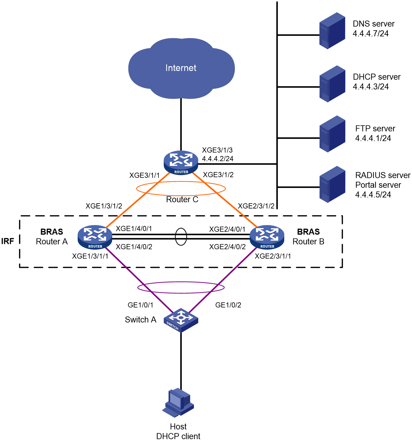
Table 5 IP planning table
|
Device |
Interface |
IP address |
Device |
Interface |
IP address |
|
DNS server |
- |
4.4.4.7/24 |
IRF (BRAS) |
RAGG1 |
- |
|
DHCP server |
- |
4.4.4.3/24 |
RAGG1023 |
100.1.1.1/24 |
|
|
FTP server |
- |
4.4.4.1/24 |
XGE1/3/1/1 |
- |
|
|
RADIUS server & portal server |
- |
4.4.4.5/24 |
XGE2/3/1/1 |
- |
|
|
Router C |
RAGG1023 |
100.1.1.2/24 |
XGE1/3/1/2 |
- |
|
|
XGE3/1/1 |
- |
XGE2/3/1/2 |
- |
||
|
XGE3/1/2 |
- |
LoopBack1 |
80.1.1.1/32 |
||
|
XGE3/1/3 |
4.4.4.2/24 |
|
|
Analysis
· To avoid the impact of a single point of failure in member devices on normal traffic forwarding, configure multichassis aggregate interfaces on the IRF fabric for traffic forwarding.
· To minimize the impact of IRF fabric split on services, configure Link Aggregation Control Protocol (LACP) Multiple Active Detection (MAD) on the IRF fabric. You need to configure LACP MAD for only one aggregate group. The intermediate device used for LACP MAD must be an H3C device and its software version used must support recognizing and processing link aggregation control protocol data units (LACPDUs) carrying active IDs. In this example, Switch A is used as the intermediate device for LACP MAD.
· To meet users' bandwidth requirements, use committed access rate (CAR) authorization for rate limiting in this example.
· Configure the following class-behavior associations to process the incoming traffic in the IPoE Web preauthentication domain:
¡ Configure a class to match traffic of the DNS server and with the user group of the preauthentication domain. Associate the class with a behavior containing the filter permit action.
¡ Configure a class to match traffic of the portal server and with the user group of the preauthentication domain. Associate the class with a behavior containing the filter permit action.
¡ Configure a class to match traffic of the internal network server and with the user group of the preauthentication domain. Associate the class with a behavior containing the filter permit action.
¡ Configure a class to match HTTP traffic with the user group of the preauthentication domain, and associate the class with a behavior containing the redirect http-to-cpu action.
¡ Configure a class to match HTTPS traffic with the user group of the preauthentication domain, and associate the class with a behavior containing the redirect https-to-cpu action.
¡ Configure a class to match IP traffic with the user group of the preauthentication domain, and associate the class with a behavior containing the redirect cpu action. (Required only for transparent authentication.)
¡ Configure a class to match IP traffic with the user group of the preauthentication domain, and associate the class with a behavior containing the filter deny action.
· Configure the following class-behavior associations to process the outgoing traffic in the IPoE Web preauthentication domain:
¡ Configure a class to match traffic of the DNS server and with the user group of the preauthentication domain. Associate the class with a behavior containing the filter permit action.
¡ Configure a class to match traffic of the portal server and with the user group of the preauthentication domain. Associate the class with a behavior containing the filter permit action.
¡ Configure a class to match traffic of the internal network server and with the user group of the preauthentication domain. Associate the class with a behavior containing the filter permit action.
¡ Configure a class to match IP traffic with the user group of the preauthentication domain, and associate the class with a behavior containing the filter deny action.
· For users to access the internal network without accounting and access the external network with non-ITA accounting after passing IPoE Web authentication, configure the following ITA policy on the BRASs:
¡ For the internal network access traffic (traffic with accounting level 2), do not specify the accounting type (do not specify the ipv4 keyword) so that ITA accounting will not be performed.
¡ Do not configure the accounting type for external network traffic on the device.
¡ Exclude the amount of ITA traffic from the overall traffic statistics that are sent to the accounting server.
Restrictions and guidelines
The DHCP server in this configuration is simulated by a device. As a best practice, use a dedicated DHCP server in actual applications.
To avoid service unavailability caused by port number conflicts, make sure the internal listening port number is not used by any well-known protocol and is not used by a TCP-based service. To view the TCP port numbers used by other services, execute the display tcp command.
Procedure
Configure IP addresses and routes
# Assign IP address 4.4.4.2/24 to Ten-GigabitEthernet 3/1/3 on Router C.
<RouterC> system-view
[RouterC] interface ten-gigabitethernet 3/1/3
[RouterC-Ten-GigabitEthernet3/1/3] ip address 4.4.4.2 24
[RouterC-Ten-GigabitEthernet3/1/3] quit
# Configure the static route from Router C to users.
[RouterC] ip route-static 192.168.0.0 24 100.1.1.1
Configure the DNS server
Configure the DNS server correctly, so that the server can parse the IPv4 URL for the Web authentication page http://www.ipv4.web.com based on the first stack through which dual-stack IPoE users come online.
|
|
NOTE: The following information uses Windows Server 2016 to describe the basic configuration of the DNS server. |
1. Install the DNS component:
a. Log in to the server, click Windows, and select Server Manager.
b. Click Add Roles and Features, and configure DNS.
c. On the Before you begin page, click Next.
d. On the Select installation type page, leave the default options (Role-based or feature-based installation), and click Next.
e. On the Select destination server page, leave the default options (Select a server from the server pool), and click Next.
f. On the Select server roles page, select DNS Server. On the Add Roles and Features Wizard page that opens, click Add Features, and then click Next.
g. On the Select features page, leave the default options, and click Next.
h. On the DNS Server page, click Next.
i. Click Install on the Confirm installation selections page and wait for the installation to complete.
j. Once installation completes, click Close to complete the installation of the DNS component.
2. Create a forward lookup zone:
a. On the Server Manager page, click Tools, and select DNS.
b. Right-click Forward Lookup Zones on the DNS Manager page and select New Zone.
c. On the New Zone Wizard page, click Next.
d. On the Zone Type page, select Primary Zone, and click Next.
e. On the Zone Name page, enter zone name ipv4.web.com.
f. On the Zone File page, leave the default configuration and click Next.
g. On the Dynamic Update page, select Do not allow dynamic updates and click Next.
h. On the New Zone Wizard page, click Finish.
i. On the DNS Manager page, click Forward Lookup Zones, right-click ipv4.web.com, and click New Host.
j. On the New Host page, enter host name www, enter IP address 4.4.4.7, and click Add Host.
The forward lookup zone has been successfully created.
3. Create a reverse lookup zone:
a. Right-click Reverse Lookup Zones on the DNS Manager page and select New Zone.
b. On the New Zone Wizard page, click Next.
c. On the Zone Type page, select Primary Zone, and click Next.
d. On the Reverse Lookup Zone Name page, select IPv4 Reverse Lookup Zone(4), and click Next.
e. On the Reverse Lookup Zone Name page, enter network ID 4.4.4, and click Next.
f. On the Zone File page, leave the default configuration and click Next.
g. On the Dynamic Update page, select Do not allow dynamic updates and click Next.
h. On the New Zone Wizard page, click Finish.
i. On the DNS Manager page, click Reverse Lookup Zones, right-click 4.4.4.in-addr.arpa.dns, and click New Pointer.
j. On the New Resource Record page, enter host IP address 4.4.4.7, enter host name www.ipv4.web.com, and click OK.
The reverse lookup zone has been successfully created.
Configure the DHCP server
# Enable DHCP.
<DHCP> system-view
[DHCP] dhcp enable
# Enable the DHCP server to return a DHCP-NAK message if the client notions of their IP addresses are incorrect.
[DHCP] dhcp server request-ip-address check
# Create IP address pool pool1 and enter its view.
[DHCP] ip pool pool1
# Specify primary subnet 192.168.0.0/24 for dynamic allocation in the address pool. Specify DNS server address 4.4.4.7 in the address pool.
[DHCP-ip-pool-pool1] network 192.168.0.0 24
[DHCP-ip-pool-pool1] dns-list 4.4.4.7
# Specify gateway address 192.168.0.1.
[DHCP-ip-pool-pool1] gateway-list 192.168.0.1
# Exclude IP address 192.168.0.1 from dynamic allocation.
[DHCP-ip-pool-pool1] forbidden-ip 192.168.0.1
[DHCP-ip-pool-pool1] quit
# Configure a route. (This example configures a default route. On a live network, configure the route as needed.)
[DHCP] ip route-static 0.0.0.0 0 4.4.4.2
Configure the RADIUS server and portal server
|
|
NOTE: This section uses the Srun software of version 4.0.9 as an example to describe how to configure basic settings of the RADIUS server and portal server. |
1. Enter http://4.4.4.5:8081 in the address bar of a browser to log in to the server. Add access devices:
# Select Device Management from the navigation tree. Click the Add Device tab. On the tab, click Add.
¡ Set the device name to BRAS.
¡ Set the NAS IP address to the IP address of interface LoopBack1 on the BRAS, 80.1.1.1.
¡ Set the device IP to 4.4.4.5.
¡ Select Huawei, H3C, and Srun Gateways from the NAS type list.
¡ Set the DM port to 3799.
¡ Set the RADIUS key to 123456.
¡ Select No from the whether to drop traffic list.
¡ Select h3c v1.2 from the portal server list.
¡ Set the portal key to 123456.
# Set the RADIUS trust. Select RADIUS from the navigation tree. Click the RADIUS Trust Settings link to enter the RADIUS trust settings page. Click Generate in the upper right corner until the trust is successfully generated. Then, restart the radius process of Srun.
# Click the RADIUS Service Settings tab, and specify the device to carry the ISP domain name in the username sent to the RADIUS server.
2. Enter https://4.4.4.5:8080 in the address bar of a browser to log in to the server. Add users:
a. Navigate to the User Management > Add Users page. Click Add.
b. Add user user1 with account user1 and password pass.
For information about deploying other configurations such as control policies and product policies, see the configuration guides for Srun.
Set up an IRF fabric
1. Configure Router A and Router B to form an IRF fabric:
# Configure member ID 1 for Router A. Create IRF port 2, and bind it to physical interfaces Ten-GigabitEthernet 4/0/1 and Ten-GigabitEthernet 4/0/2.
<RouterA> system-view
[RouterA] irf member 1 priority 2
[RouterA] interface ten-gigabitethernet 4/0/1
[RouterA-Ten-GigabitEthernet4/0/1] port link-mode bridge
[RouterA-Ten-GigabitEthernet4/0/1] quit
[RouterA] interface ten-gigabitethernet 4/0/2
[RouterA-Ten-GigabitEthernet4/0/2] port link-mode bridge
[RouterA-Ten-GigabitEthernet4/0/2] quit
[RouterA] irf-port 2
[RouterA-irf-port2] port group interface ten-gigabitethernet 4/0/1
[RouterA-irf-port2] port group interface ten-gigabitethernet 4/0/2
[RouterA-irf-port2] quit
# Save the current configuration into the next startup configuration file.
[RouterA] quit
<RouterA> save
# Enable IRF mode.
<RouterA> system-view
[RouterA] chassis convert mode irf
The device will switch to IRF mode and reboot. Continue?[Y/N]:y
You are recommended to save the current running configuration and specify the configuration file for the next startup. Now save the running configuration to the next-startup configuration file? [Y/N]:y
Please input the file name(*.cfg)[cfa0:/test.cfg]
(To leave the existing filename unchanged, press the enter key):
cfa0:/test.cfg exists, overwrite? [Y/N]:y
Validating file. Please wait...
Saved the current configuration to mainboard device successfully.
Do you want to convert the content of the next startup configuration file cfa0:/test.cfg to make it available in IRF mode? [Y/N]:y
Now rebooting, please wait...
After reboot, Router A forms an IRF fabric with only one member device.
# Configure member ID 2 for Router B. Create IRF port 1, and bind it to physical interfaces Ten-GigabitEthernet 4/0/1 and Ten-GigabitEthernet 4/0/2.
<RouterB> system-view
[RouterB] irf member 2 priority 1
[RouterB] interface ten-gigabitethernet 4/0/1
[RouterB-Ten-GigabitEthernet4/0/1] port link-mode bridge
[RouterB-Ten-GigabitEthernet4/0/1] quit
[RouterB] interface ten-gigabitethernet 4/0/2
[RouterB-Ten-GigabitEthernet4/0/2] port link-mode bridge
[RouterB-Ten-GigabitEthernet4/0/2] quit
[RouterB] irf-port 1
[RouterB-irf-port1] port group interface ten-gigabitethernet 4/0/1
[RouterB-irf-port1] port group interface ten-gigabitethernet 4/0/2
[RouterB-irf-port1] quit
# Save the current configuration into the next startup configuration file.
[RouterB] quit
<RouterB> save
# Enable IRF mode.
<RouterB> system-view
[RouterB] chassis convert mode irf
The device will switch to IRF mode and reboot. Continue?[Y/N]:y
You are recommended to save the current running configuration and specify the configuration file for the next startup. Now save the running configuration to the next-startup configuration file? [Y/N]:y
Please input the file name(*.cfg)[cfa0:/test.cfg]
(To leave the existing filename unchanged, press the enter key):
cfa0:/test.cfg exists, overwrite? [Y/N]:y
Validating file. Please wait...
Saved the current configuration to mainboard device successfully.
Do you want to convert the content of the next startup configuration file cfa0:/test.cfg to make it available in IRF mode? [Y/N]:y
Now rebooting, please wait...
After reboot, Router B forms an IRF fabric with Router A.
2. Configure downlink services of the IRF fabric:
a. Configure LACP MAD:
|
|
NOTE: In this example, Router A acts as the master member in the IRF fabric and acts as the BRAS in the IPoE configuration. For ease of understanding, Router A is referred to as IRF in the IRF fabric configuration section and BRAS in the IPoE configuration section. |
After the IRF fabric is set up, you can configure various service modules. Once the IRF fabric is set up, you can log in to any member device for configuration. The default device name is the name of the master member device, which is Router A in this example.
# Create a dynamic aggregation group numbered 1 for connecting to Switch A and enable LACP MAD.
<IRF> system-view
[IRF] interface route-aggregation 1
[IRF-Route-Aggregation1] link-aggregation mode dynamic
[IRF-Route-Aggregation1] mad enable
You need to assign a domain ID (range: 0-4294967295)
[Current domain is: 0]:
The assigned domain ID is: 0
MAD LACP only enable on dynamic aggregation interface.
[IRF-Route-Aggregation1] quit
# Assign the interfaces connecting to Switch A to aggregation group 1.
[IRF] interface ten-gigabitethernet 1/3/1/1
[IRF-Ten-GigabitEthernet1/3/1/1] port link-aggregation group 1
[IRF-Ten-GigabitEthernet1/3/1/1] quit
[IRF] interface ten-gigabitethernet 2/3/1/1
[IRF-Ten-GigabitEthernet2/3/1/1] port link-aggregation group 1
[IRF-Ten-GigabitEthernet2/3/1/1] quit
b. Configure Switch A:
# Create a dynamic aggregation group numbered 1 for connecting to the IRF fabric. This aggregation group is also used for LACP MAD.
<SwitchA> system-view
[SwitchA] interface bridge-aggregation 1
[SwitchA-Bridge-Aggregation1] link-aggregation mode dynamic
[SwitchA-Bridge-Aggregation1] quit
# Assign the interfaces connecting to the IRF fabric to aggregation group 1.
[SwitchA] interface gigabitethernet 1/0/1
[SwitchA-GigabitEthernet1/0/1] port link-aggregation group 1
[SwitchA-GigabitEthernet1/0/1] quit
[SwitchA] interface gigabitethernet 1/0/2
[SwitchA-GigabitEthernet1/0/2] port link-aggregation group 1
[SwitchA-GigabitEthernet1/0/2] quit
3. Configure uplink services of the IRF fabric:
a. Configure an aggregation group on the IRF fabric:
# Create a dynamic aggregation group numbered 1023 for connecting to border router Router C. Assign IP address 100.1.1.1/24 to the aggregate interface.
[IRF] interface route-aggregation 1023
[IRF-Route-Aggregation1023] link-aggregation mode dynamic
[IRF-Route-Aggregation1023] ip address 100.1.1.1 24
[IRF-Route-Aggregation1023] quit
# Assign the interfaces connecting to Router C to aggregation group 1023.
[IRF] interface ten-gigabitethernet 1/3/1/2
[IRF-Ten-GigabitEthernet1/3/1/2] port link-aggregation group 1023
[IRF-Ten-GigabitEthernet1/3/1/2] quit
[IRF] interface ten-gigabitethernet 2/3/1/2
[IRF-Ten-GigabitEthernet2/3/1/2] port link-aggregation group 1023
[IRF-Ten-GigabitEthernet2/3/1/2] quit
# Configure a static default route to Router C for accessing the servers and Internet.
[IRF] ip route-static 0.0.0.0 0 100.1.1.2
b. Configure Router C:
|
|
NOTE: The section only covers the configuration for connecting to the IRF fabric and does not describe the routing protocol used for the external network. |
# Create a dynamic aggregation group numbered 1023 for connecting to the IRF fabric. Assign IP address 100.1.1.2/24 to the aggregate interface.
<RouterC> system-view
[RouterC] interface route-aggregation 1023
[RouterC-Route-Aggregation1023] link-aggregation mode dynamic
[RouterC-Route-Aggregation1023] ip address 100.1.1.2 24
[RouterC-Route-Aggregation1023] quit
# Assign the interfaces connecting to the IRF fabric to aggregation group 1023.
[RouterC] interface ten-gigabitethernet 3/1/1
[RouterC-Ten-GigabitEthernet3/1/1] port link-aggregation group 1023
[RouterC-Ten-GigabitEthernet3/1/1] quit
[RouterC] interface ten-gigabitethernet 3/1/2
[RouterC-Ten-GigabitEthernet3/1/2] port link-aggregation group 1023
[RouterC-Ten-GigabitEthernet3/1/2] quit
Configure BRAS
1. Configure the DHCP relay agent:
# Enable DHCP globally.
[BRAS] dhcp enable
# Create DHCP relay address pool pool1, and specify the gateway address and the DHCP server for the address pool.
[BRAS] ip pool pool1 bas remote
[BRAS-ip-pool-pool1] gateway 192.168.0.1 24
[BRAS-ip-pool-pool1] remote-server 4.4.4.3
[BRAS-ip-pool-pool1] quit
# Enable the DHCPv4 relay agent on the interface.
[BRAS] interface route-aggregation 1
[BRAS–Route-Aggregation1] dhcp select relay
[BRAS–Route-Aggregation1] quit
2. Create an IPv4 portal authentication server named newpt1. Specify IP address 4.4.4.5 and plaintext password 123456 for the server.
[BRAS] portal server newpt1
[BRAS-portal-server-newpt1] ip 4.4.4.5 key simple 123456
[BRAS-portal-server-newpt1] quit
3. Specify the HTTPS redirect listening port number. Make sure it does not conflict with a port in use. To view the TCP port numbers used by other services, execute the display tcp command.
[BRAS] http-redirect https-port 11111
4. Configure the device to get user access information from ARP entries.
[BRAS] portal access-info trust arp
5. Create local user groups:
# Create a user group named pre for the preauthentication domain.
[BRAS] user-group pre
New user group added.
[BRAS-ugroup-pre] quit
# Create a fail-permit user group named flee.
[BRAS] user-group flee
New user group added.
[BRAS-ugroup-flee] quit
# Create a Web user group named web.
[BRAS] user-group web
New user group added.
[BRAS-ugroup-web] quit
6. Configure QoS:
a. Configure the ACLs for users in the preauthentication domain:
# Create IPv4 advanced ACL dns_permit to match packets destined to the DNS server for users in user group pre.
[BRAS] acl advanced name dns_permit
[BRAS-acl-ipv4-adv-dns_permit] rule 0 permit ip destination 4.4.4.7 0 user-group pre
[BRAS-acl-ipv4-adv-dns_permit] quit
# Create IPv4 advanced ACL web_permit to match packets destined to the portal server for users in user group pre.
[BRAS] acl advanced name web_permit
[BRAS-acl-ipv4-adv-web_permit] rule 0 permit ip destination 4.4.4.5 0 user-group pre
[BRAS-acl-ipv4-adv-web_permit] quit
# Create IPv4 advanced ACL neiwang to match packets destined to the internal network server for users in user groups pre and web.
[BRAS] acl advanced name neiwang
[BRAS-acl-ipv4-adv-neiwang] rule 0 permit ip destination 4.4.4.1 0 user-group pre
[BRAS-acl-ipv4-adv-neiwang] rule 10 permit ip destination 4.4.4.1 0 user-group web
[BRAS-acl-ipv4-adv-neiwang] quit
# Create IPv4 advanced ACL web_http to match TCP packets with destination port 80 (HTTP packets) for users in user group pre.
[BRAS] acl advanced name web_http
[BRAS-acl-ipv4-adv-web_http] rule 0 permit tcp destination-port eq www user-group pre
[BRAS-acl-ipv4-adv-web_http] quit
# Create IPv4 advanced ACL web_https to match TCP packets with destination port 443 (HTTPS packets) for users in user group pre.
[BRAS] acl advanced name web_https
[BRAS-acl-ipv4-adv-web_https] rule 0 permit tcp destination-port eq 443 user-group pre
[BRAS-acl-ipv4-adv-web_https] quit
# Create IPv4 advanced ACL ip to match IP packets for users in user group pre.
[BRAS] acl advanced name ip
[BRAS-acl-ipv4-adv-ip] rule 0 permit ip user-group pre
[BRAS-acl-ipv4-adv-ip] quit
# Create IPv4 advanced ACL neiwang_out to match packets sourced from the internal network server for users in user groups pre and web.
[BRAS] acl advanced name neiwang_out
[BRAS-acl-ipv4-adv-neiwang_out] rule 0 permit ip source 4.4.4.1 0 user-group pre
[BRAS-acl-ipv4-adv-neiwang_out] rule 10 permit ip source 4.4.4.1 0 user-group web
[BRAS-acl-ipv4-adv-neiwang_out] quit
# Create IPv4 advanced ACL web_out to match packets sourced from the portal server for users in user group pre.
[BRAS] acl advanced name web_out
[BRAS-acl-ipv4-adv-web_out] rule 0 permit ip source 4.4.4.5 0 user-group pre
[BRAS-acl-ipv4-adv-web_out] quit
Create IPv4 advanced ACL dns_out to match packets sourced from the DNS server for users in user group pre.
[BRAS] acl advanced name dns_out
[BRAS-acl-ipv4-adv-dns_out] rule 0 permit ip source 4.4.4.7 0 user-group pre
[BRAS-acl-ipv4-adv-dns_out] quit
b. Configure traffic classes for users in the preauthentication domain:
# Create a traffic class named dns_permit, and use ACL dns_permit as the match criterion.
[BRAS] traffic classifier dns_permit operator or
[BRAS-classifier-dns_permit] if-match acl name dns_permit
[BRAS-classifier-dns_permit] quit
# Create a traffic class named web_permit, and use ACL web_permit as the match criterion.
[BRAS] traffic classifier web_permit operator or
[BRAS-classifier-web_permit] if-match acl name web_permit
[BRAS-classifier-web_permit] quit
# Create a traffic class named neiwang, and use ACL neiwang as the match criterion.
[BRAS] traffic classifier neiwang operator or
[BRAS-classifier-neiwang] if-match acl name neiwang
[BRAS-classifier-neiwang] quit
# Create a traffic class named web_http and use ACL web_http as the match criterion.
[BRAS] traffic classifier web_http operator or
[BRAS-classifier-web_http] if-match acl name web_http
[BRAS-classifier-web_http] quit
# Create a traffic class named web_https, and use ACL web_https as the match criterion.
[BRAS] traffic classifier web_https operator or
[BRAS-classifier-web_https] if-match acl name web_https
[BRAS-classifier-web_https] quit
# Create a traffic class named web_deny, and use ACL ip as the match criterion.
[BRAS] traffic classifier web_deny operator or
[BRAS-classifier-web_deny] if-match acl name ip
[BRAS-classifier-web_deny] quit
# Create a traffic class named neiwang_out, and use ACL neiwang_out as the match criterion.
[BRAS] traffic classifier neiwang_out operator or
[BRAS-classifier-neiwang_out] if-match acl name neiwang_out
[BRAS-classifier-neiwang_out] quit
# Create a traffic class named web_out, and use ACL web_out as the match criterion.
[BRAS] traffic classifier web_out operator or
[BRAS-classifier-web_out] if-match acl name web_out
[BRAS-classifier-web_out] quit
# Create a traffic class named dns_out, and use ACL dns_out as the match criterion.
[BRAS] traffic classifier dns_out operator or
[BRAS-classifier-dns_out] if-match acl name dns_out
[BRAS-classifier-dns_out] quit
c. Configure traffic behaviors:
# Configure a traffic behavior named dns_permit to permit packets.
[BRAS] traffic behavior dns_permit
[BRAS-behavior-dns_permit] filter permit
[BRAS-behavior-dns_permit] free account
[BRAS-behavior-dns_permit] quit
# Configure a traffic behavior named web_permit to permit packets.
[BRAS] traffic behavior web_permit
[BRAS-behavior-web_permit] filter permit
[BRAS-behavior-web_permit] free account
[BRAS-behavior-web_permit] quit
# Configure a traffic behavior named neiwang to permit packets and set the accounting level to 2.
[BRAS] traffic behavior neiwang
[BRAS-behavior-neiwang] remark account-level 2
[BRAS-behavior-neiwang] quit
# Configure a traffic behavior named web_http to redirect HTTP packets to the CPU.
[BRAS] traffic behavior web_http
[BRAS-behavior-web_http] redirect http-to-cpu
[BRAS-behavior-web_http] quit
# Configure a traffic behavior named web_https to redirect HTTPS packets to the CPU.
[BRAS] traffic behavior web_https
[BRAS-behavior-web_https] redirect https-to-cpu
[BRAS-behavior-web_https] quit
# Create a traffic behavior named web_deny to deny packets.
[BRAS] traffic behavior web_deny
[BRAS-behavior-web_deny] filter deny
[BRAS-behavior-web_deny] free account
[BRAS-behavior-web_deny] quit
# Configure a traffic behavior named neiwang_out to permit packets and set the accounting level to 2.
[BRAS] traffic behavior neiwang_out
[BRAS-behavior-neiwang_out] remark account-level 2
[BRAS-behavior-neiwang_out] quit
# Configure a traffic behavior named web_out to permit packets.
[BRAS] traffic behavior web_out
[BRAS-behavior-web_out] filter permit
[BRAS-behavior-web_out] free account
[BRAS-behavior-web_out] quit
# Configure a traffic behavior named dns_out to permit packets.
[BRAS] traffic behavior dns_out
[BRAS-behavior-dns_out] filter permit
[BRAS-behavior-dns_out] free account
[BRAS-behavior-dns_out] quit
d. Configure QoS policies:
# Configure an inbound QoS policy named web.
[BRAS] qos policy web
# Associate traffic classes with traffic behaviors. For users in user group pre:
- Permit packets destined to the DNS server, portal server, and internal network server.
- Redirect packets with destination ports 80 (HTTP) and 443 (HTTPS) to the CPU.
- Deny any other packets.
[BRAS-qospolicy-web] classifier dns_permit behavior dns_permit
[BRAS-qospolicy-web] classifier web_permit behavior web_permit
[BRAS-qospolicy-web] classifier neiwang behavior neiwang
[BRAS-qospolicy-web] classifier web_http behavior web_http
[BRAS-qospolicy-web] classifier web_https behavior web_https
[BRAS-qospolicy-web] classifier web_deny behavior web_deny
[BRAS-qospolicy-web] quit
# Configure an outbound QoS policy named out.
[BRAS] qos policy out
# Associate traffic classes with traffic behaviors to permit packet sourced from the DNS server, portal server, and internal network server for users in user group pre and deny any other packets.
[BRAS-qospolicy-out] classifier dns_out behavior dns_out
[BRAS-qospolicy-out] classifier web_out behavior web_out
[BRAS-qospolicy-out] classifier neiwang_out behavior neiwang_out
[BRAS-qospolicy-out] classifier web_deny behavior web_deny
[BRAS-qospolicy-out] quit
e. Apply QoS policies:
# Apply QoS policy web to the incoming traffic. To identify whether the QoS policy takes effect, execute the display qos policy global inbound command.
[BRAS] qos apply policy web global inbound
# Apply QoS policy out to the outgoing traffic. To identify whether the QoS policy takes effect, execute the display qos policy global outbound command.
[BRAS] qos apply policy out global outbound
7. Configure a RADIUS scheme:
# Create RADIUS scheme rs1, and enter its view.
[BRAS] radius scheme rs1
# Configure the primary authentication and accounting servers and the keys for secure RADIUS authentication and accounting communication for the RADIUS scheme.
[BRAS-radius-rs1] primary authentication 4.4.4.5
[BRAS-radius-rs1] primary accounting 4.4.4.5
[BRAS-radius-rs1] key authentication simple 123456
[BRAS-radius-rs1] key accounting simple 123456
# Exclude the ISP name from the username sent to the RADIUS server.
[BRAS-radius-rs1] user-name-format without-domain
# Specify source IP address 80.1.1.1 for outgoing RADIUS packets.
[BRAS-radius-rs1] nas-ip 80.1.1.1
[BRAS-radius-rs1] quit
# Specify the DAC as 4.4.4.5. Set the shared key to 123456 in plaintext form for secure communication between the DAS and DAC. Make sure the plaintext key is the same on both ends.
[BRAS] radius dynamic-author server
[BRAS-radius-da-server] client ip 4.4.4.5 key simple 123456
[BRAS-radius-da-server] quit
8. Configure an ITA policy:
# Create an ITA policy named ita1 and enter its view.
[BRAS] ita policy ita1
# Configure an accounting method for the ITA policy.
[BRAS-ita-policy-ita1] accounting-method radius-scheme rs1
# Configure an accounting level.
[BRAS-ita-policy-ita1] accounting-level 2 car inbound cir 5120 outbound cir 5120
# Exclude the amount of ITA traffic from the overall traffic statistics that are sent to the accounting server.
[BRAS-ita-policy-ita1] traffic-separate enable
[BRAS-ita-policy-ita1] quit
9. Configure the preauthentication domain and Web authentication domain:
# Configure the preauthentication domain for IPoE users.
[BRAS] domain name dm1
[BRAS-isp-dm1] authentication ipoe none
[BRAS-isp-dm1] authorization ipoe none
[BRAS-isp-dm1] accounting ipoe none
# Configure the authorization user group and address pool in the preauthentication domain.
[BRAS-isp-dm1] authorization-attribute user-group pre
[BRAS-isp-dm1] authorization-attribute ip-pool pool1
# Configure the Web authentication page URL.
[BRAS-isp-dm1] web-server url http://www.ipv4.web.com
# Apply ITA policy ita1 to the domain.
[BRAS-isp-dm1] ita-policy ita1
[BRAS-isp-dm1] quit
# Configure the Web authentication domain for IPoE users.
[BRAS] domain name dm2
[BRAS-isp-dm2] authentication ipoe radius-scheme rs1
[BRAS-isp-dm2] authorization ipoe radius-scheme rs1
[BRAS-isp-dm2] accounting ipoe radius-scheme rs1
[BRAS-isp-dm2] authorization-attribute car inbound cir 5120 outbound cir 5120
# Apply ITA policy ita1 to the domain.
[BRAS-isp-dm2] ita-policy ita1
[BRAS-isp-dm2] quit
10. Configure track for Web fail-permit:
a. Create an NQA operation with administrator name admin and operation tag test1
# Create an NQA operation with administrator name admin and operation tag test1.
[BRAS] nqa entry admin test1
# Configure the operation type as ICMP echo.
[BRAS-nqa-admin-test1] type icmp-echo
# Specify 4.4.4.5 as the destination IPv4 address for the operation.
[BRAS-nqa-admin-test1-icmp-echo] destination ip 4.4.4.5
# Configure the operation to repeat every 100 milliseconds.
[BRAS-nqa-admin-test1-icmp-echo] frequency 100
# Create reaction entry 1. Trigger collaboration if the number of consecutive probe failures reaches 5.
[BRAS-nqa-admin-test1-icmp-echo] reaction 1 checked-element probe-fail threshold-type consecutive 5 action-type trigger-only //Use "trigger-only" instead of "trap-only" at the end of the command.
# Set the maximum number of history records to 10 for the operation.
[BRAS-nqa-admin-test1-icmp-echo] history-record enable
[BRAS-nqa-admin-test1-icmp-echo] history-record number 10
[BRAS-nqa-admin-test1-icmp-echo] quit
# Perform the operation until you stop it.
[BRAS] nqa schedule admin test1 start-time now lifetime forever
b. Configure track entry 1, and associate it with reaction entry 1 of the NQA operation with administrator name admin and operation tag test1.
[BRAS] track 1 nqa entry admin test1 reaction 1
[BRAS-track-1] quit
c. Configure a tracked list:
# Create Boolean AND list 100 and enter its view.
[BRAS] track 100 list boolean and
# Add track entry 1 as an object to the tracked list.
[BRAS-track-100] object 1
11. Configure IPoE:
# Enable IPoE and configure the Layer 2 access mode.
[BRAS] interface route-aggregation 1
[BRAS–Route-Aggregation1] ip subscriber l2-connected enable
# Configure the Web authentication method for IPoE users.
[BRAS–Route-Aggregation1] ip subscriber authentication-method web
The operation may cut all users on this interface. Continue?[Y/N]:y
# Configure the Web preauthentication domain as dm1 and Web authentication domain as dm2.
[BRAS–Route-Aggregation1] ip subscriber pre-auth domain dm1
[BRAS–Route-Aggregation1] ip subscriber web-auth domain dm2
# Enable unclassified-IPv4 packet initiation (with the matching-user parameter) and ARP packet initiation for restoring abnormally logged-out users.
[BRAS–Route-Aggregation1] ip subscriber initiator unclassified-ip enable matching-user
[BRAS–Route-Aggregation1] ip subscriber initiator arp enable
# Associate fail-permit user group flee with tracked list 100.
[BRAS–Route-Aggregation1] ip subscriber pre-auth track 100 fail-permit user-group flee
[BRAS–Route-Aggregation1] quit
12. Configure attack defense:
¡ Configure source MAC-based ARP attack detection:
# Enable the source MAC-based ARP attack detection feature and specify the filter handling method.
[BRAS] arp source-mac filter
# Set the check interval for source MAC-based ARP attack detection to 5 seconds.
[BRAS] arp source-mac check-interval 5
# Set the threshold for source MAC-based ARP attack detection to 30.
[BRAS] arp source-mac threshold 30
# Set the aging time for ARP attack entries to 300 seconds.
[BRAS] arp source-mac aging-time 300
¡ Configure DHCP flood attack protection:
# Enable DHCP flood attack protection on interface Route-Aggregation1.
[BRAS] interface route-aggregation 1
[BRAS-Route-Aggregation1] dhcp flood-protection enable
[BRAS–Route-Aggregation1] quit
# Configure the device to allow a maximum of 30 DHCP packets per 10000 milliseconds from each DHCP client.
[BRAS] dhcp flood-protection threshold 30 10000
# Set the DHCP flood attack entry aging time to 300 seconds.
[BRAS] dhcp flood-protection aging-time 300
¡ Enable ICMP fast reply:
[BRAS] ip icmp fast-reply enable
¡ Configure TCP SYN flood attack prevention:
# Enable flow-based TCP SYN flood attack prevention.
[BRAS] tcp anti-syn-flood flow-based enable
# Set the check interval to 20 seconds for flow-based TCP SYN flood attack prevention.
[BRAS] tcp anti-syn-flood flow-based check-interval 20
# Set the threshold to 2000 for triggering flow-based TCP SYN flood attack prevention.
[BRAS] tcp anti-syn-flood flow-based threshold 2000
# Set the flow-based TCP SYN flood attack prevention duration to 5 minutes.
[BRAS] tcp anti-syn-flood flow-based duration 5
¡ Configure HTTP/HTTPS attack defense:
# Enable destination IP-based IPoE HTTP/HTTPS attack defense.
[BRAS] ip subscriber http-defense destination-ip enable
# Trigger attack defense when the total number of HTTP/HTTPS packets sent to the same destination IP address within 300 seconds reaches 6000.
[BRAS] ip subscriber http-defense destination-ip threshold 6000 interval 300
¡ Configure HTTP packet fast reply:
# Enable HTTP packet fast reply on interface Route-Aggregation 1.
[BRAS] interface route-aggregation 1
[BRAS-Route-Aggregation1] ip subscriber http-fast-reply enable
[BRAS-Route-Aggregation1] quit
Verifying the configuration
# After a user passes preauthentication, use the following command to view online IPoE user information. The output shows that the user obtains IPv4 address 192.168.0.2.
[BRAS] display access-user interface route-aggregation 1
UserID Interface IP address MAC address S-/C-VLAN
Username Access type
IPv6 address
0x5c RAGG1 192.168.0.2 000c-29a6-b656 -/-
000c29a6b656 L2 IPoE dynamic
-
# After the user passes authentication in the preauthentication domain, log in to the Web interface.
# Enter the username and password, and then click Log In to perform Web authentication on the authentication page. Use the following command to view online IPoE user information.
[BRAS] display access-user interface route-aggregation 1
UserID Interface IP address MAC address S-/C-VLAN
Username Access type
IPv6 address
0x5c RAGG1 192.168.0.2 000c-29a6-b656 -/-
user1 Web auth
-
Configuration files
· DHCP server:
#
dhcp enable
dhcp server request-ip-address check
#
ip pool pool1
gateway-list 192.168.0.1
network 192.168.0.0 mask 255.255.255.0
dns-list 4.4.4.7
forbidden-ip 192.168.0.1
#
interface Ten-GigabitEthernet3/1/1
ip address 4.4.4.3 255.255.255.0
#
ip route-static 0.0.0.0 0 4.4.4.2
#
· Router C:
#
interface Route-Aggregation1023
ip address 100.1.1.2 255.255.255.0
link-aggregation mode dynamic
#
interface Ten-GigabitEthernet3/1/1
port link-aggregation group 1023
#
interface Ten-GigabitEthernet3/1/2
port link-aggregation group 1023
#
interface Ten-GigabitEthernet3/1/3
ip address 4.4.4.2 255.255.255.0
#
ip route-static 192.168.0.0 24 100.1.1.1
#
· IRF (BRAS):
#
irf mac-address persistent always
irf auto-update enable
irf auto-merge enable
undo irf link-delay
irf member 1 priority 2
irf member 2 priority 1
#
irf-port 1/2
port group interface Ten-GigabitEthernet1/4/0/1 mode enhanced
port group interface Ten-GigabitEthernet1/4/0/2 mode enhanced
#
irf-port 2/1
port group interface Ten-GigabitEthernet2/4/0/1 mode enhanced
port group interface Ten-GigabitEthernet2/4/0/2 mode enhanced
#
track 1 nqa entry admin test1 reaction 1
#
track 100 list boolean and
object 1
#
dhcp enable
#
traffic classifier dns_out operator or
if-match acl name dns_out
#
traffic classifier dns_permit operator or
if-match acl name dns_permit
#
traffic classifier neiwang operator or
if-match acl name neiwang
#
traffic classifier neiwang_out operator or
if-match acl name neiwang_out
#
traffic classifier web_deny operator or
if-match acl name ip
#
traffic classifier web_http operator or
if-match acl name web_http
#
traffic classifier web_https operator or
if-match acl name web_https
#
traffic classifier web_out operator or
if-match acl name web_out
#
traffic classifier web_permit operator or
if-match acl name web_permit
#
traffic behavior dns_out
filter permit
free account
#
traffic behavior dns_permit
filter permit
free account
#
traffic behavior neiwang
remark account-level 2
#
traffic behavior neiwang_out
remark account-level 2
#
traffic behavior web_deny
filter deny
free account
#
traffic behavior web_http
redirect http-to-cpu
#
traffic behavior web_https
redirect https-to-cpu
#
traffic behavior web_out
filter permit
free account
#
traffic behavior web_permit
filter permit
free account
#
qos policy out
classifier dns_out behavior dns_out
classifier web_out behavior web_out
classifier neiwang_out behavior neiwang_out
classifier web_deny behavior web_deny
#
qos policy web
classifier dns_permit behavior dns_permit
classifier web_permit behavior web_permit
classifier neiwang behavior neiwang
classifier web_http behavior web_http
classifier web_https behavior web_https
classifier web_deny behavior web_deny
#
interface Route-Aggregation1
link-aggregation mode dynamic
mad enable
ip subscriber initiator arp enable
dhcp select relay
dhcp flood-protection enable
ip subscriber l2-connected enable
ip subscriber http-fast-reply enable
ip subscriber authentication-method web
ip subscriber pre-auth domain dm1
ip subscriber web-auth domain dm2
ip subscriber initiator unclassified-ip enable matching-user
ip subscriber pre-auth track 100 fail-permit user-group flee
#
interface Route-Aggregation1023
ip address 100.1.1.1 255.255.255.0
link-aggregation mode dynamic
#
interface Ten-GigabitEthernet1/3/1/1
port link-aggregation group 1
#
interface Ten-GigabitEthernet2/3/1/1
port link-aggregation group 1
#
interface Ten-GigabitEthernet1/3/1/2
port link-aggregation group 1023
#
interface Ten-GigabitEthernet2/3/1/2
port link-aggregation group 1023
#
qos apply policy web global inbound
qos apply policy out global outbound
#
ip pool pool1 bas remote
gateway 192.168.0.1 mask 255.255.255.0
remote-server 4.4.4.3
#
nqa entry admin test1
type icmp-echo
destination ip 4.4.4.5
frequency 100
history-record enable
history-record number 10
reaction 1 checked-element probe-fail threshold-type consecutive 5 action-type trigger-only
#
nqa schedule admin test1 start-time now lifetime forever
#
acl advanced name dns_out
rule 0 permit ip source 4.4.4.7 0 user-group pre
#
acl advanced name dns_permit
rule 0 permit ip destination 4.4.4.7 0 user-group pre
#
acl advanced name ip
rule 0 permit ip user-group pre
#
acl advanced name neiwang
rule 0 permit ip destination 4.4.4.1 0 user-group pre
rule 10 permit ip destination 4.4.4.1 0 user-group web
#
acl advanced name neiwang_out
rule 0 permit ip source 4.4.4.1 0 user-group pre
rule 0 permit ip source 4.4.4.1 0 user-group web
#
acl advanced name web_http
rule 0 permit tcp destination-port eq www user-group pre
#
acl advanced name web_https
rule 0 permit tcp destination-port eq 443 user-group pre
#
acl advanced name web_out
rule 0 permit ip source 4.4.4.5 0 user-group pre
#
acl advanced name web_permit
rule 0 permit ip destination 4.4.4.5 0 user-group pre
#
radius scheme rs1
primary authentication 4.4.4.5
primary accounting 4.4.4.5
key authentication cipher $c$3$FhQVcgn3kq1exL0CdTzatcgc9xF9vL3ZOw==
key accounting cipher $c$3$ntIHBRM4ZkG+2JRZQTdKmNl0kYJmhZz5Zg==
user-name-format without-domain
nas-ip 80.1.1.1
#
radius dynamic-author server
client ip 4.4.4.5 key cipher $c$3$lYC2ERe8ts2gtE6M2xfoDDB8NmGw6J9v/Q==
#
ita policy ita1
accounting-method radius-scheme rs1
accounting-level 2 car inbound cir 5120 outbound cir 5120
traffic-separate enable
#
ip route-static 0.0.0.0 24 100.1.1.2
#
domain name dm1
authorization-attribute user-group pre
authorization-attribute ip-pool pool1
authentication ipoe none
authorization ipoe none
accounting ipoe none
web-server url http://www.ipv4.web.com
#
domain name dm2
authorization-attribute car inbound cir 5120 outbound cir 5120
authentication ipoe radius-scheme rs1
authorization ipoe radius-scheme rs1
accounting ipoe radius-scheme rs1
#
user-group pre
#
user-group web
#
portal server newpt1
ip 4.4.4.5 key cipher $c$3$UnoFeLybwld9jDwLnHJQptDE7YZry2EVlw==
#
portal access-info trust arp
#
http-redirect https-port 11111
#
tcp anti-syn-flood flow-based enable
tcp anti-syn-flood flow-based threshold 2000
tcp anti-syn-flood flow-based check-interval 20
#
dhcp flood-protection threshold 30 10000
#
ip icmp fast-reply enable
#
ip subscriber http-defense destination-ip enable
#
arp source-mac filter
#
Layer 2 common Web authentication configuration example for IPv6 single-stack IPoE users (DHCP relay agent+authorized address pool)
This example uses a basic wired authentication scenario. In actual applications, both wired and wireless users can use IPv6 single-stack IP over Ethernet (IPoE) Web authentication.
This example uses DHCPv6 to assign IPv6 addresses, which is more suitable for wired users. Android devices do not support DHCPv6, so they cannot obtain an IPv6 address to access IPv6 network resources.
Network configuration
As shown in Figure 34, Router A and Router B are two broadband remote access servers (BRASs) of a school, and they form an Intelligent Resilient Framework (IRF) fabric to provide IPoE access services for school users. Configure the network to meet the following requirements:
· The Dynamic Host Configuration Protocol (DHCP) client accesses the BRASs through a Layer 2 network by using IPoE.
· The BRASs request IP addresses from the remote DHCP server as a DHCP relay agent.
· A server with Srun software installed acts as a Remote Authentication Dial-In User Service (RADIUS) server, portal authentication server, and portal Web server at the same time.
· The FTP server is an internal network server.
· After users pass IPoE Web authentication, the rate limit is 5 Mbps.
· Configure basic attack protection features for some protocol packets (for example, ND and DHCP) on BRASs to prevent illegal packets from impacting the network.
Figure 35 Network diagram

Table 6 IP planning table
|
Device |
Interface |
IP address |
Device |
Interface |
IP address |
|
DNS server |
- |
4::7/64 |
IRF (BRAS) |
RAGG1 |
- |
|
DHCP server |
- |
4::3/64 |
RAGG1023 |
100::1/64 |
|
|
FTP server |
- |
4::1/64 |
XGE1/3/1/1 |
- |
|
|
RADIUS server & portal server |
- |
4::5/64 |
XGE2/3/1/1 |
- |
|
|
Router C |
RAGG1023 |
100::2/64 |
XGE1/3/1/2 |
- |
|
|
XGE3/1/1 |
- |
XGE2/3/1/2 |
- |
||
|
XGE3/1/2 |
- |
LoopBack1 |
80::1/128 |
||
|
XGE3/1/3 |
4::2/64 |
|
|
Analysis
· To avoid the impact of a single point of failure in member devices on normal traffic forwarding, configure multichassis aggregate interfaces on the IRF fabric for traffic forwarding.
· To minimize the impact of IRF fabric split on services, configure Link Aggregation Control Protocol (LACP) Multiple Active Detection (MAD) on the IRF fabric. You need to configure LACP MAD for only one aggregate group. The intermediate device used for LACP MAD must be an H3C device and its software version used must support recognizing and processing link aggregation control protocol data units (LACPDUs) carrying active IDs. In this example, Switch A is used as the intermediate device for LACP MAD.
· To meet users' bandwidth requirements, use committed access rate (CAR) authorization for rate limiting in this example.
· Configure the following class-behavior associations to process the incoming traffic in the IPoE Web preauthentication domain:
¡ Configure a class to match traffic of the DNS server and with the user group of the preauthentication domain. Associate the class with a behavior containing the filter permit action.
¡ Configure a class to match traffic of the portal server and with the user group of the preauthentication domain. Associate the class with a behavior containing the filter permit action.
¡ Configure a class to match traffic of the internal network server and with the user group of the preauthentication domain. Associate the class with a behavior containing the filter permit action.
¡ Configure a class to match HTTP traffic with the user group of the preauthentication domain, and associate the class with a behavior containing the redirect http-to-cpu action.
¡ Configure a class to match HTTPS traffic with the user group of the preauthentication domain, and associate the class with a behavior containing the redirect https-to-cpu action.
¡ Configure a class to match IP traffic with the user group of the preauthentication domain, and associate the class with a behavior containing the redirect cpu action. (Required only for transparent authentication.)
¡ Configure a class to match IP traffic with the user group of the preauthentication domain, and associate the class with a behavior containing the filter deny action.
· Configure the following class-behavior associations to process the outgoing traffic in the IPoE Web preauthentication domain:
¡ Configure a class to match traffic of the DNS server and with the user group of the preauthentication domain. Associate the class with a behavior containing the filter permit action.
¡ Configure a class to match traffic of the portal server and with the user group of the preauthentication domain. Associate the class with a behavior containing the filter permit action.
¡ Configure a class to match traffic of the internal network server and with the user group of the preauthentication domain. Associate the class with a behavior containing the filter permit action.
¡ Configure a class to match IP traffic with the user group of the preauthentication domain, and associate the class with a behavior containing the filter deny action.
Restrictions and guidelines
The DHCP server in this configuration is simulated by a device. As a best practice, use a dedicated DHCP server in actual applications.
To avoid service unavailability caused by port number conflicts, make sure the internal listening port number is not used by any well-known protocol and is not used by a TCP-based service. To view the TCP port numbers used by other services, execute the display tcp command.
Procedure
Configure IP addresses and routes
# Assign IP address 4::2/64 to Ten-GigabitEthernet 3/1/3 on Router C.
<RouterC> system-view
[RouterC] interface ten-gigabitethernet 3/1/3
[RouterC-Ten-GigabitEthernet3/1/3] ipv6 address 4::2 64
[RouterC-Ten-GigabitEthernet3/1/3] quit
# Configure the static route from Router C to users.
[RouterC] ipv6 route-static 192:: 64 100::1
Configure the DNS server
Configure the DNS server correctly, so that the server can parse the IPv6 URL for the Web authentication page http://www.ipv6.web.com based on the first stack through which dual-stack IPoE users come online.
|
|
NOTE: The following information uses Windows Server 2016 to describe the basic configuration of the DNS server. |
1. Install the DNS component:
a. Log in to the server, click Windows, and select Server Manager.
b. Click Add Roles and Features, and configure DNS.
c. On the Before you begin page, click Next.
d. On the Select installation type page, leave the default options (Role-based or feature-based installation), and click Next.
e. On the Select destination server page, leave the default options (Select a server from the server pool), and click Next.
f. On the Select server roles page, select DNS Server. On the Add Roles and Features Wizard page that opens, click Add Features, and then click Next.
g. On the Select features page, leave the default options, and click Next.
h. On the DNS Server page, click Next.
i. Click Install on the Confirm installation selections page and wait for the installation to complete.
j. Once installation completes, click Close to complete the installation of the DNS component.
2. Create a forward lookup zone:
a. On the Server Manager page, click Tools, and select DNS.
b. Right-click Forward Lookup Zones on the DNS Manager page and select New Zone.
c. On the New Zone Wizard page, click Next.
d. On the Zone Type page, select Primary Zone, and click Next.
e. On the Zone Name page, enter zone name ipv6.web.com.
f. On the Zone File page, leave the default configuration and click Next.
g. On the Dynamic Update page, select Do not allow dynamic updates and click Next.
h. On the New Zone Wizard page, click Finish.
i. On the DNS Manager page, click Forward Lookup Zones, right-click ipv6.web.com, and click New Host.
j. On the New Host page, enter host name www, enter IP address 4::7, and click Add Host.
The forward lookup zone has been successfully created.
3. Create a reverse lookup zone:
a. Right-click Reverse Lookup Zones on the DNS Manager page and select New Zone.
b. On the New Zone Wizard page, click Next.
c. On the Zone Type page, select Primary Zone, and click Next.
d. On the Reverse Lookup Zone Name page, select IPv6 Reverse Lookup Zone(6), and click Next.
e. On the Reverse Lookup Zone Name page, enter network ID 4000:0000:0000:0000::/64, and click Next.
f. On the Zone File page, leave the default configuration and click Next.
g. On the Dynamic Update page, select Do not allow dynamic updates and click Next.
h. On the New Zone Wizard page, click Finish.
i. On the DNS Manager page, click Reverse Lookup Zones, right-click 0.0.0.0.0.0.0.0.0.0.0.0.0.0.0.4.in-addr.arpa.dns, and click New Pointer.
j. On the New Resource Record page, enter host IP address 4000.0000.0000.0000.0000.0000.0000.0007, enter host name www.ipv6.web.com, and click OK.
The reverse lookup zone has been successfully created.
Configure the DHCPv6 server
# Create a DHCPv6 address pool pool2 and enter its view.
<DHCP> system-view
[DHCP] ipv6 pool pool2
# Specify IPv6 address network segment 192::/64 for dynamic allocation in the address pool. Specify DNS server address 4::7 in the address pool.
[DHCP-ipv6-pool-pool2] network 192::/64
[DHCP-ipv6-pool-pool2] dns-server 4::7
[DHCP-ipv6-pool-pool2] quit
# Exclude IP address 192::1 from dynamic allocation.
[DHCP] ipv6 dhcp server forbidden-address 192::1
# Enable the DHCPv6 server on Ten-GigabitEthernet 3/1/1.
[DHCP] interface ten-gigabitethernet 3/1/1
[DHCP-Ten-GigabitEthernet3/1/1] ipv6 dhcp select server
[DHCP-Ten-GigabitEthernet3/1/1] quit
# Configure a route. (This example configures a default route. On a live network, configure the route as needed.)
[DHCP] ipv6 route-static :: 0 4::2
Configure the RADIUS server and portal server
|
|
NOTE: This section uses the Srun software of version 4.0.9 as an example to describe how to configure basic settings of the RADIUS server and portal server. |
1. Enter http://[4::5]:8081 in the address bar of a browser to log in to the server. Add access devices:
# Select Device Management from the navigation tree. Click the Add Device tab. On the tab, click Add.
¡ Set the device name to BRAS.
¡ Set the NAS IP address to the IP address of interface LoopBack1 on the BRAS, 80::1.
¡ Set the device IP to 4::5.
¡ Select Huawei, H3C, and Srun Gateways from the NAS type list.
¡ Set the DM port to 3799.
¡ Set the RADIUS key to 123456.
¡ Select No from the whether to drop traffic list.
¡ Select h3c v1.2 from the portal server list.
¡ Set the portal key to 123456.
# Set the RADIUS trust. Select RADIUS from the navigation tree. Click the RADIUS Trust Settings link to enter the RADIUS trust settings page. Click Generate in the upper right corner until the trust is successfully generated. Then, restart the radius process of Srun.
# Click the RADIUS Service Settings tab, and specify the device to carry the ISP domain name in the username sent to the RADIUS server.
2. Enter https://[4::5]:8080 in the address bar of a browser to log in to the server. Add users:
a. Navigate to the User Management > Add Users page. Click Add.
b. Add user user1 with account user1 and password pass.
For information about deploying other configurations such as control policies and product policies, see the configuration guides for Srun.
Set up an IRF fabric
1. Configure Router A and Router B to form an IRF fabric:
# Configure member ID 1 for Router A. Create IRF port 2, and bind it to physical interfaces Ten-GigabitEthernet 4/0/1 and Ten-GigabitEthernet 4/0/2.
<RouterA> system-view
[RouterA] irf member 1 priority 2
[RouterA] interface ten-gigabitethernet 4/0/1
[RouterA-Ten-GigabitEthernet4/0/1] port link-mode bridge
[RouterA-Ten-GigabitEthernet4/0/1] quit
[RouterA] interface ten-gigabitethernet 4/0/2
[RouterA-Ten-GigabitEthernet4/0/2] port link-mode bridge
[RouterA-Ten-GigabitEthernet4/0/2] quit
[RouterA] irf-port 2
[RouterA-irf-port2] port group interface ten-gigabitethernet 4/0/1
[RouterA-irf-port2] port group interface ten-gigabitethernet 4/0/2
[RouterA-irf-port2] quit
# Save the current configuration into the next startup configuration file.
[RouterA] quit
<RouterA> save
# Enable IRF mode.
<RouterA> system-view
[RouterA] chassis convert mode irf
The device will switch to IRF mode and reboot. Continue?[Y/N]:y
You are recommended to save the current running configuration and specify the configuration file for the next startup. Now save the running configuration to the next-startup configuration file? [Y/N]:y
Please input the file name(*.cfg)[cfa0:/test.cfg]
(To leave the existing filename unchanged, press the enter key):
cfa0:/test.cfg exists, overwrite? [Y/N]:y
Validating file. Please wait...
Saved the current configuration to mainboard device successfully.
Do you want to convert the content of the next startup configuration file cfa0:/test.cfg to make it available in IRF mode? [Y/N]:y
Now rebooting, please wait...
After reboot, Router A forms an IRF fabric with only one member device.
# Configure member ID 2 for Router B. Create IRF port 1, and bind it to physical interfaces Ten-GigabitEthernet 4/0/1 and Ten-GigabitEthernet 4/0/2.
<RouterB> system-view
[RouterB] irf member 2 priority 1
[RouterB] interface ten-gigabitethernet 4/0/1
[RouterB-Ten-GigabitEthernet4/0/1] port link-mode bridge
[RouterB-Ten-GigabitEthernet4/0/1] quit
[RouterB] interface ten-gigabitethernet 4/0/2
[RouterB-Ten-GigabitEthernet4/0/2] port link-mode bridge
[RouterB-Ten-GigabitEthernet4/0/2] quit
[RouterB] irf-port 1
[RouterB-irf-port1] port group interface ten-gigabitethernet 4/0/1
[RouterB-irf-port1] port group interface ten-gigabitethernet 4/0/2
[RouterB-irf-port1] quit
# Save the current configuration into the next startup configuration file.
[RouterB] quit
<RouterB> save
# Enable IRF mode.
<RouterB> system-view
[RouterB] chassis convert mode irf
The device will switch to IRF mode and reboot. Continue?[Y/N]:y
You are recommended to save the current running configuration and specify the configuration file for the next startup. Now save the running configuration to the next-startup configuration file? [Y/N]:y
Please input the file name(*.cfg)[cfa0:/test.cfg]
(To leave the existing filename unchanged, press the enter key):
cfa0:/test.cfg exists, overwrite? [Y/N]:y
Validating file. Please wait...
Saved the current configuration to mainboard device successfully.
Do you want to convert the content of the next startup configuration file cfa0:/test.cfg to make it available in IRF mode? [Y/N]:y
Now rebooting, please wait...
After reboot, Router B forms an IRF fabric with Router A.
2. Configure downlink services of the IRF fabric:
a. Configure LACP MAD:
|
|
NOTE: In this example, Router A acts as the master member in the IRF fabric and acts as the BRAS in the IPoE configuration. For ease of understanding, Router A is referred to as IRF in the IRF fabric configuration section and BRAS in the IPoE configuration section. |
After the IRF fabric is set up, you can configure various service modules. Once the IRF fabric is set up, you can log in to any member device for configuration. The default device name is the name of the master member device, which is Router A in this example.
# Create a dynamic aggregation group numbered 1 for connecting to Switch A and enable LACP MAD.
<IRF> system-view
[IRF] interface route-aggregation 1
[IRF-Route-Aggregation1] link-aggregation mode dynamic
[IRF-Route-Aggregation1] mad enable
You need to assign a domain ID (range: 0-4294967295)
[Current domain is: 0]:
The assigned domain ID is: 0
MAD LACP only enable on dynamic aggregation interface.
[IRF-Route-Aggregation1] quit
# Assign the interfaces connecting to Switch A to aggregation group 1.
[IRF] interface ten-gigabitethernet 1/3/1/1
[IRF-Ten-GigabitEthernet1/3/1/1] port link-aggregation group 1
[IRF-Ten-GigabitEthernet1/3/1/1] quit
[IRF] interface ten-gigabitethernet 2/3/1/1
[IRF-Ten-GigabitEthernet2/3/1/1] port link-aggregation group 1
[IRF-Ten-GigabitEthernet2/3/1/1] quit
b. Configure Switch A:
# Create a dynamic aggregation group numbered 1 for connecting to the IRF fabric. This aggregation group is also used for LACP MAD.
<SwitchA> system-view
[SwitchA] interface bridge-aggregation 1
[SwitchA-Bridge-Aggregation1] link-aggregation mode dynamic
[SwitchA-Bridge-Aggregation1] quit
# Assign the interfaces connecting to the IRF fabric to aggregation group 1.
[SwitchA] interface gigabitethernet 1/0/1
[SwitchA-GigabitEthernet1/0/1] port link-aggregation group 1
[SwitchA-GigabitEthernet1/0/1] quit
[SwitchA] interface gigabitethernet 1/0/2
[SwitchA-GigabitEthernet1/0/2] port link-aggregation group 1
[SwitchA-GigabitEthernet1/0/2] quit
3. Configure uplink services of the IRF fabric:
a. Configure an aggregation group on the IRF fabric:
# Create a dynamic aggregation group numbered 1023 for connecting to border router Router C. Assign IPv6 address 100::1/64 to the aggregate interface.
[IRF] interface route-aggregation 1023
[IRF-Route-Aggregation1023] link-aggregation mode dynamic
[IRF-Route-Aggregation1023] ipv6 address 100::1 64
[IRF-Route-Aggregation1023] quit
# Assign the interfaces connecting to Router C to aggregation group 1023.
[IRF] interface ten-gigabitethernet 1/3/1/2
[IRF-Ten-GigabitEthernet1/3/1/2] port link-aggregation group 1023
[IRF-Ten-GigabitEthernet1/3/1/2] quit
[IRF] interface ten-gigabitethernet 2/3/1/2
[IRF-Ten-GigabitEthernet2/3/1/2] port link-aggregation group 1023
[IRF-Ten-GigabitEthernet2/3/1/2] quit
# Configure a static default route to Router C for accessing the servers and Internet.
[IRF] ipv6 route-static :: 0 100::2
b. Configure Router C:
|
|
NOTE: The section only covers the configuration for connecting to the IRF fabric and does not describe the routing protocol used for the external network. |
# Create a dynamic aggregation group numbered 1023 for connecting to the IRF fabric. Assign IPv6 address 100::2/64 to the aggregate interface.
<RouterC> system-view
[RouterC] interface route-aggregation 1023
[RouterC-Route-Aggregation1023] link-aggregation mode dynamic
[RouterC-Route-Aggregation1023] ipv6 address 100::2 64
[RouterC-Route-Aggregation1023] quit
# Assign the interfaces connecting to the IRF fabric to aggregation group 1023.
[RouterC] interface ten-gigabitethernet 3/1/1
[RouterC-Ten-GigabitEthernet3/1/1] port link-aggregation group 1023
[RouterC-Ten-GigabitEthernet3/1/1] quit
[RouterC] interface ten-gigabitethernet 3/1/2
[RouterC-Ten-GigabitEthernet3/1/2] port link-aggregation group 1023
[RouterC-Ten-GigabitEthernet3/1/2] quit
Configure BRAS
1. Configure the DHCP relay agent:
# Create DHCP relay address pool pool2, and specify the gateway address and the DHCPv6 server for the address pool.
[BRAS] ipv6 pool pool2
[BRAS-ipv6-pool-pool2] gateway-list 192::1
[BRAS-ipv6-pool-pool2] network 192::/64 export-route
[BRAS-ipv6-pool-pool2] remote-server 4::3
[BRAS-ipv6-pool-pool2] quit
# Configure the interface to automatically generate an IPv6 link-local address, which will serve as the gateway for users.
[BRAS] interface route-aggregation 1
[BRAS–Route-Aggregation1] ipv6 address auto link-local
# Enable the DHCPv6 relay agent on the interface.
[BRAS–Route-Aggregation1] dhcp select relay
# Disable RA message suppression on the interface. Configure the configuration flag for managed address as 1 so that the host can obtain IPv6 addresses through the DHCPv6 server. Configure the configuration flag for other information as 1 so that the host can obtain other information except for IPv6 addresses through the DHCPv6 server.
[BRAS–Route-Aggregation1] undo ipv6 nd ra halt
[BRAS–Route-Aggregation1] ipv6 nd autoconfig managed-address-flag
[BRAS–Route-Aggregation1] ipv6 nd autoconfig other-flag
[BRAS–Route-Aggregation1] quit
2. Create an IPv6 portal authentication server named newpt2. Specify IP address 4::5 and plaintext password 123456 for the server.
[BRAS] portal server newpt2
[BRAS-portal-server-newpt2] ipv6 4::5 key simple 123456
[BRAS-portal-server-newpt2] quit
3. Specify the HTTPS redirect listening port number. Make sure it does not conflict with a port in use. To view the TCP port numbers used by other services, execute the display tcp command.
[BRAS] http-redirect https-port 11111
4. Configure the device to get user access information from ND entries.
[BRAS] portal access-info trust nd
5. Create local user groups:
# Create a user group named pre for the preauthentication domain.
[BRAS] user-group pre
New user group added.
[BRAS-ugroup-pre] quit
6. Configure QoS:
a. Configure the ACLs for users in the preauthentication domain:
# Create IPv6 advanced ACL dns_permit to match packets destined to the DNS server for users in group pre.
[BRAS] acl ipv6 advanced name dns_permit
[BRAS-acl-ipv6-adv-dns_permit] rule 0 permit ipv6 destination 4::7 128 user-group pre
[BRAS-acl-ipv6-adv-dns_permit] quit
# Create IPv6 advanced ACL web_permit to match packets destined to the portal server for users in user group pre.
[BRAS] acl ipv6 advanced name web_permit
[BRAS-acl-ipv6-adv-web_permit] rule 0 permit ipv6 destination 4::5 128 user-group pre
[BRAS-acl-ipv6-adv-web_permit] quit
# Create IPv6 advanced ACL neiwang to match packets destined to the internal network server for users in user groups pre and web.
[BRAS] acl ipv6 advanced name neiwang
[BRAS-acl-ipv6-adv-neiwang] rule 0 permit ipv6 destination 4::1 128 user-group pre
[BRAS-acl-ipv6-adv-neiwang] quit
# Create IPv6 advanced ACL web_http to match TCP packets with destination port 80 (HTTP packets) for users in user group pre.
[BRAS] acl ipv6 advanced name web_http
[BRAS-acl-ipv6-adv-web_http] rule 0 permit tcp destination-port eq www user-group pre
[BRAS-acl-ipv6-adv-web_http] quit
# Create IPv6 advanced ACL web_https to match TCP packets with destination port 443 (HTTPS packets) for users in group pre.
[BRAS] acl ipv6 advanced name web_https
[BRAS-acl-ipv6-adv-web_https] rule 0 permit tcp destination-port eq 443 user-group pre
[BRAS-acl-ipv6-adv-web_https] quit
# Create IPv6 advanced ACL ip to match IP packets for users in user group pre.
[BRAS] acl ipv6 advanced name ip
[BRAS-acl-ipv6-adv-ip] rule 0 permit ipv6 user-group pre
[BRAS-acl-ipv6-adv-ip] quit
# Create IPv6 advanced ACL neiwang_out to match packets sourced from the internal network server for users in user groups pre and web.
[BRAS] acl ipv6 advanced name neiwang_out
[BRAS-acl-ipv6-adv-neiwang_out] rule 0 permit ipv6 source 4::1 128 user-group pre
[BRAS-acl-ipv6-adv-neiwang_out] quit
# Create IPv6 advanced ACL web_out to match packets sourced from the portal server for users in user group pre.
[BRAS] acl ipv6 advanced name web_out
[BRAS-acl-ipv6-adv-web_out] rule 0 permit ipv6 source 4::5 128 user-group pre
[BRAS-acl-ipv6-adv-web_out] quit
Create IPv6 advanced ACL dns_out to match packets sourced from the DNS server for users in group pre.
[BRAS] acl ipv6 advanced name dns_out
[BRAS-acl-ipv6-adv-dns_out] rule 0 permit ipv6 source 4::7 128 user-group pre
[BRAS-acl-ipv6-adv-dns_out] quit
b. Configure traffic classes for users in the preauthentication domain:
# Create a traffic class named dns_permit, and use ACL dns_permit as the match criterion.
[BRAS] traffic classifier dns_permit operator or
[BRAS-classifier-dns_permit] if-match acl ipv6 name dns_permit
[BRAS-classifier-dns_permit] quit
# Create a traffic class named web_permit, and use ACL web_permit as the match criterion.
[BRAS] traffic classifier web_permit operator or
[BRAS-classifier-web_permit] if-match acl ipv6 name web_permit
[BRAS-classifier-web_permit] quit
# Create a traffic class named neiwang, and use ACL neiwang as the match criterion.
[BRAS] traffic classifier neiwang operator or
[BRAS-classifier-neiwang] if-match acl ipv6 name neiwang
[BRAS-classifier-neiwang] quit
# Create a traffic class named web_http and use ACL web_http as the match criterion.
[BRAS] traffic classifier web_http operator or
[BRAS-classifier-web_http] if-match acl ipv6 name web_http
[BRAS-classifier-web_http] quit
# Create a traffic class named web_https, and use ACL web_https as the match criterion.
[BRAS] traffic classifier web_https operator or
[BRAS-classifier-web_https] if-match acl ipv6 name web_https
[BRAS-classifier-web_https] quit
# Create a traffic class named web_deny, and use ACL ip as the match criterion.
[BRAS] traffic classifier web_deny operator or
[BRAS-classifier-web_deny] if-match acl ipv6 name ip
[BRAS-classifier-web_deny] quit
# Create a traffic class named neiwang_out, and use ACL neiwang_out as the match criterion.
[BRAS] traffic classifier neiwang_out operator or
[BRAS-classifier-neiwang_out] if-match acl ipv6 name neiwang_out
[BRAS-classifier-neiwang_out] quit
# Create a traffic class named web_out, and use ACL web_out as the match criterion.
[BRAS] traffic classifier web_out operator or
[BRAS-classifier-web_out] if-match acl ipv6 name web_out
[BRAS-classifier-web_out] quit
# Create a traffic class named dns_out, and use ACL dns_out as the match criterion.
[BRAS] traffic classifier dns_out operator or
[BRAS-classifier-dns_out] if-match acl ipv6 name dns_out
[BRAS-classifier-dns_out] quit
c. Configure traffic behaviors:
# Configure a traffic behavior named dns_permit to permit packets.
[BRAS] traffic behavior dns_permit
[BRAS-behavior-dns_permit] filter permit
[BRAS-behavior-dns_permit] free account
[BRAS-behavior-dns_permit] quit
# Configure a traffic behavior named web_permit to permit packets.
[BRAS] traffic behavior web_permit
[BRAS-behavior-web_permit] filter permit
[BRAS-behavior-web_permit] free account
[BRAS-behavior-web_permit] quit
# Configure a traffic behavior named neiwang to permit packets.
[BRAS] traffic behavior neiwang
[BRAS-behavior-neiwang] filter permit
[BRAS-behavior-neiwang] free account
[BRAS-behavior-neiwang] quit
# Configure a traffic behavior named web_http to redirect packets to the CPU.
[BRAS] traffic behavior web_http
[BRAS-behavior-web_http] redirect http-to-cpu
[BRAS-behavior-web_http] quit
# Configure a traffic behavior named web_https to redirect packets to the CPU.
[BRAS] traffic behavior web_https
[BRAS-behavior-web_https] redirect https-to-cpu
[BRAS-behavior-web_https] quit
# Create a traffic behavior named web_deny to deny packets.
[BRAS] traffic behavior web_deny
[BRAS-behavior-web_deny] filter deny
[BRAS-behavior-web_deny] free account
[BRAS-behavior-web_deny] quit
# Configure a traffic behavior named neiwang_out to permit packets.
[BRAS] traffic behavior neiwang_out
[BRAS-behavior-neiwang_out] filter permit
[BRAS-behavior-neiwang_out] free account
[BRAS-behavior-neiwang_out] quit
# Configure a traffic behavior named web_out to permit packets.
[BRAS] traffic behavior web_out
[BRAS-behavior-web_out] filter permit
[BRAS-behavior-web_out] free account
[BRAS-behavior-web_out] quit
# Configure a traffic behavior named dns_out to permit packets.
[BRAS] traffic behavior dns_out
[BRAS-behavior-dns_out] filter permit
[BRAS-behavior-dns_out] free account
[BRAS-behavior-dns_out] quit
d. Configure QoS policies:
# Configure an inbound QoS policy named web.
[BRAS] qos policy web
# Associate traffic classes with traffic behaviors. For users in user group pre:
- Permit packets destined to the DNS server, portal server, and internal network server.
- Redirect packets with destination ports 80 (HTTP) and 443 (HTTPS) to the CPU.
- Deny any other packets.
[BRAS-qospolicy-web] classifier dns_permit behavior dns_permit
[BRAS-qospolicy-web] classifier web_permit behavior web_permit
[BRAS-qospolicy-web] classifier neiwang behavior neiwang
[BRAS-qospolicy-web] classifier web_http behavior web_http
[BRAS-qospolicy-web] classifier web_https behavior web_https
[BRAS-qospolicy-web] classifier web_deny behavior web_deny
[BRAS-qospolicy-web] quit
# Configure an outbound QoS policy named out.
[BRAS] qos policy out
# Associate traffic classes with traffic behaviors to permit packet sourced from the DNS server, portal server, and internal network server for users in user group pre and deny any other packets.
[BRAS-qospolicy-out] classifier dns_out behavior dns_out
[BRAS-qospolicy-out] classifier web_out behavior web_out
[BRAS-qospolicy-out] classifier neiwang_out behavior neiwang_out
[BRAS-qospolicy-out] classifier web_deny behavior web_deny
[BRAS-qospolicy-out] quit
e. Apply QoS policies:
# Apply QoS policy web to the incoming traffic. To identify whether the QoS policy takes effect, execute the display qos policy global inbound command.
[BRAS] qos apply policy web global inbound
# Apply QoS policy out to the outgoing traffic. To identify whether the QoS policy takes effect, execute the display qos policy global outbound command.
[BRAS] qos apply policy out global outbound
7. Configure a RADIUS scheme:
# Create RADIUS scheme rs1, and enter its view.
[BRAS] radius scheme rs1
# Configure the primary authentication and accounting servers and the keys for secure RADIUS authentication and accounting communication for the RADIUS scheme.
[BRAS-radius-rs1] primary authentication ipv6 4::5
[BRAS-radius-rs1] primary accounting ipv6 4::5
[BRAS-radius-rs1] key authentication simple 123456
[BRAS-radius-rs1] key accounting simple 123456
# Exclude the ISP name from the username sent to the RADIUS server.
[BRAS-radius-rs1] user-name-format without-domain
# Specify source IPv6 address 80::1 for outgoing RADIUS packets.
[BRAS-radius-rs1] nas-ip ipv6 80::1
[BRAS-radius-rs1] quit
# Specify the DAC as 4::5. Set the shared key to 123456 in plaintext form for secure communication between the DAS and DAC. Make sure the plaintext key is the same on both ends.
[BRAS] radius dynamic-author server
[BRAS-radius-da-server] client ipv6 4::5 key simple 123456
[BRAS-radius-da-server] quit
8. Configure the preauthentication domain and Web authentication domain:
# Configure the preauthentication domain for IPoE users.
[BRAS] domain name dm1
[BRAS-isp-dm1] authentication ipoe none
[BRAS-isp-dm1] authorization ipoe none
[BRAS-isp-dm1] accounting ipoe none
# Configure the authorization user group and address pool in the preauthentication domain.
[BRAS-isp-dm1] authorization-attribute user-group pre
[BRAS-isp-dm1] authorization-attribute ipv6-pool pool2
# Configure the Web authentication page URL.
[BRAS-isp-dm1] web-server ipv6-url http://www.ipv6.web.com
[BRAS-isp-dm1] quit
# Configure the Web authentication domain for IPoE users.
[BRAS] domain name dm2
[BRAS-isp-dm2] authentication ipoe radius-scheme rs1
[BRAS-isp-dm2] authorization ipoe radius-scheme rs1
[BRAS-isp-dm2] accounting ipoe radius-scheme rs1
[BRAS-isp-dm2] authorization-attribute car inbound cir 5120 outbound cir 5120
[BRAS-isp-dm2] quit
9. Configure IPoE:
# Enable IPoE and configure the Layer 2 access mode.
[BRAS] interface route-aggregation 1
[BRAS–Route-Aggregation1] ip subscriber l2-connected enable
# Configure the Web authentication method for IPoE users.
[BRAS–Route-Aggregation1] ip subscriber authentication-method web
The operation may cut all users on this interface. Continue?[Y/N]:y
# Configure the Web preauthentication domain as dm1 and Web authentication domain as dm2.
[BRAS–Route-Aggregation1] ip subscriber pre-auth domain dm1
[BRAS–Route-Aggregation1] ip subscriber web-auth domain dm2
# Enable unclassified-IPv6 packet initiation (with the matching-user parameter) and NS/NA packet initiation for restoring abnormally logged-out users.
[BRAS–Route-Aggregation1] ip subscriber initiator unclassified-ipv6 enable matching-user
[BRAS–Route-Aggregation1] ip subscriber initiator nsna enable
[BRAS–Route-Aggregation1] quit
10. Configure attack defense:
¡ Configure source MAC-based ND attack detection:
# Enable the source MAC-based ND attack detection feature and specify the filter handling method.
[BRAS] ipv6 nd source-mac filter
# Set the check interval for source MAC-based ND attack detection to 5 seconds.
[BRAS] ipv6 nd source-mac check-interval 5
# Set the threshold for source MAC-based ND attack detection to 30 packets.
[BRAS] ipv6 nd source-mac threshold 30
# Set the aging time for ND attack entries to 300 seconds.
[BRAS] ipv6 nd source-mac aging-time 300
¡ Configure DHCPv6 flood attack protection:
# Enable DHCPv6 flood attack protection on interface Route-Aggregation1.
[BRAS] interface route-aggregation 1
[BRAS-Route-Aggregation1] ipv6 dhcp flood-protection enable
[BRAS–Route-Aggregation1] quit
# Configure the device to allow a maximum of 30 DHCPv6 packets per 10000 milliseconds from each DHCPv6 client.
[BRAS] ipv6 dhcp flood-protection threshold 30 10000
# Set the DHCPv6 flood attack entry aging time to 300 seconds.
[BRAS] ipv6 dhcp flood-protection aging-time 300
¡ Enable ICMPv6 fast reply:
[BRAS] ipv6 icmpv6 fast-reply enable
¡ Configure TCP SYN flood attack prevention:
# Enable flow-based TCP SYN flood attack prevention.
[BRAS] tcp anti-syn-flood flow-based enable
# Set the check interval to 20 seconds for flow-based TCP SYN flood attack prevention.
[BRAS] tcp anti-syn-flood flow-based check-interval 20
# Set the threshold to 2000 for triggering flow-based TCP SYN flood attack prevention.
[BRAS] tcp anti-syn-flood flow-based threshold 2000
# Set the flow-based TCP SYN flood attack prevention duration to 5 minutes.
[BRAS] tcp anti-syn-flood flow-based duration 5
¡ Configure HTTP/HTTPS attack defense:
# Enable destination IP-based IPoE HTTP/HTTPS attack defense.
[BRAS] ip subscriber http-defense destination-ip enable
# Trigger attack defense when the total number of HTTP/HTTPS packets sent to the same destination IP address within 300 seconds reaches 6000.
[BRAS] ip subscriber http-defense destination-ip threshold 6000 interval 300
¡ Configure HTTP packet fast reply:
# Enable HTTP packet fast reply on interface Route-Aggregation 1.
[BRAS] interface route-aggregation 1
[BRAS-Route-Aggregation1] ip subscriber http-fast-reply enable
[BRAS-Route-Aggregation1] quit
Verifying the configuration
# After a user passes preauthentication, use the following command to view online IPoE user information. The output shows that the user obtains IPv6 address 192::2.
[BRAS] display access-user interface route-aggregation 1
UserID Interface IP address MAC address S-/C-VLAN
Username Access type
IPv6 address
0x5c RAGG1 - 000c-29a6-b656 -/-
000c29a6b656 L2 IPoE dynamic
192::2
# After the user passes authentication in the preauthentication domain, log in to the Web interface.
# Enter the username and password, and then click Log In to perform Web authentication on the authentication page. Use the following command to view online IPoE user information.
[BRAS] display access-user interface route-aggregation 1
UserID Interface IP address MAC address S-/C-VLAN
Username Access type
IPv6 address
0x5c RAGG1 - 000c-29a6-b656 -/-
user1 Web auth
192::2
Configuration files
· DHCP server:
#
ipv6 dhcp server forbidden-address 192::1
#
ipv6 pool pool2
network 192::/64
dns-server 4::7
#
interface Ten-GigabitEthernet3/1/1
ipv6 dhcp select server
ipv6 address 4::3/64
#
ipv6 route-static :: 0 4::2
#
· Router C:
#
interface Route-Aggregation1023
ipv6 address 100::2/64
link-aggregation mode dynamic
#
interface Ten-GigabitEthernet3/1/1
port link-aggregation group 1023
#
interface Ten-GigabitEthernet3/1/2
port link-aggregation group 1023
#
interface Ten-GigabitEthernet3/1/3
ipv6 address 4::2/64
#
ipv6 route-static 192:: 64 100::1
#
· IRF (BRAS):
#
irf mac-address persistent always
irf auto-update enable
irf auto-merge enable
undo irf link-delay
irf member 1 priority 2
irf member 2 priority 1
#
irf-port 1/2
port group interface Ten-GigabitEthernet1/4/0/1 mode enhanced
port group interface Ten-GigabitEthernet1/4/0/2 mode enhanced
#
irf-port 2/1
port group interface Ten-GigabitEthernet2/4/0/1 mode enhanced
port group interface Ten-GigabitEthernet2/4/0/2 mode enhanced
#
traffic classifier dns_out operator or
if-match acl ipv6 name dns_out
#
traffic classifier dns_permit operator or
if-match acl ipv6 name dns_permit
#
traffic classifier neiwang operator or
if-match acl ipv6 name neiwang
#
traffic classifier neiwang_out operator or
if-match acl ipv6 name neiwang_out
#
traffic classifier web_deny operator or
if-match acl ipv6 name ip
#
traffic classifier web_http operator or
if-match acl ipv6 name web_http
#
traffic classifier web_https operator or
if-match acl ipv6 name web_https
#
traffic classifier web_out operator or
if-match acl ipv6 name web_out
#
traffic classifier web_permit operator or
if-match acl ipv6 name web_permit
#
traffic behavior dns_out
filter permit
free account
#
traffic behavior dns_permit
filter permit
free account
#
traffic behavior neiwang
filter permit
free account
#
traffic behavior neiwang_out
filter permit
free account
#
traffic behavior web_deny
filter deny
free account
#
traffic behavior web_http
redirect http-to-cpu
#
traffic behavior web_https
redirect https-to-cpu
#
traffic behavior web_out
filter permit
free account
#
traffic behavior web_permit
filter permit
free account
#
qos policy out
classifier dns_out behavior dns_out
classifier web_out behavior web_out
classifier neiwang_out behavior neiwang_out
classifier web_deny behavior web_deny
#
qos policy web
classifier dns_permit behavior dns_permit
classifier web_permit behavior web_permit
classifier neiwang behavior neiwang
classifier web_http behavior web_http
classifier web_https behavior web_https
classifier web_deny behavior web_deny
#
interface Route-Aggregation1
link-aggregation mode dynamic
mad enable
ipv6 dhcp select relay
ipv6 dhcp flood-protection enable
ipv6 address auto link-local
ipv6 nd autoconfig managed-address-flag
ipv6 nd autoconfig other-flag
undo ipv6 nd ra halt
ip subscriber initiator nsna enable
ip subscriber l2-connected enable
ip subscriber http-fast-reply enable
ip subscriber authentication-method web
ip subscriber pre-auth domain dm1
ip subscriber web-auth domain dm2
ip subscriber initiator unclassified-ipv6 enable matching-user
#
interface Route-Aggregation1023
ipv6 address 100::1/64
link-aggregation mode dynamic
#
interface Ten-GigabitEthernet1/3/1/1
port link-aggregation group 1
#
interface Ten-GigabitEthernet2/3/1/1
port link-aggregation group 1
#
interface Ten-GigabitEthernet1/3/1/2
port link-aggregation group 1023
#
interface Ten-GigabitEthernet2/3/1/2
port link-aggregation group 1023
#
qos apply policy web global inbound
qos apply policy out global outbound
#
ipv6 pool pool2
network 192::/64 export-route
gateway-list 192::1
remote-server 4::3
#
acl ipv6 advanced name dns_out
rule 0 permit ipv6 source 4::7/128 user-group pre
#
acl ipv6 advanced name dns_permit
rule 0 permit ipv6 destination 4::7/128 user-group pre
#
acl ipv6 advanced name ip
rule 0 permit ipv6 user-group pre
#
acl ipv6 advanced name neiwang
rule 0 permit ipv6 destination 4::1/128 user-group pre
#
acl ipv6 advanced name neiwang_out
rule 0 permit ipv6 source 4::1/128 user-group pre
#
acl ipv6 advanced name web_http
rule 0 permit tcp destination-port eq www user-group pre
#
acl ipv6 advanced name web_https
rule 0 permit tcp destination-port eq 443 user-group pre
#
acl ipv6 advanced name web_out
rule 0 permit ipv6 source 4::5/128 user-group pre
#
acl ipv6 advanced name web_permit
rule 0 permit ipv6 destination 4::5/128 user-group pre
#
radius scheme rs1
primary authentication ipv6 4::5
primary accounting ipv6 4::5
key authentication cipher $c$3$FhQVcgn3kq1exL0CdTzatcgc9xF9vL3ZOw==
key accounting cipher $c$3$ntIHBRM4ZkG+2JRZQTdKmNl0kYJmhZz5Zg==
user-name-format without-domain
nas-ip ipv6 80::1
#
radius dynamic-author server
client ipv6 4::5 key cipher $c$3$lYC2ERe8ts2gtE6M2xfoDDB8NmGw6J9v/Q==
#
ipv6 route-static :: 0 100::2
#
domain name dm1
authorization-attribute user-group pre
authorization-attribute ip-pool pool1
authorization-attribute ipv6-pool pool2
authentication ipoe none
authorization ipoe none
accounting ipoe none
web-server ipv6-url http://www.ipv6.web.com
#
domain name dm2
authorization-attribute car inbound cir 5120 outbound cir 5120
authentication ipoe radius-scheme rs1
authorization ipoe radius-scheme rs1
accounting ipoe radius-scheme rs1
#
user-group pre
#
portal server newpt2
ipv6 4::5 key cipher $c$3$HxisNWeML9fhYRS+7umwGbYwAkL+KGiCjw==
#
portal access-info trust nd
#
http-redirect https-port 11111
#
tcp anti-syn-flood flow-based enable
tcp anti-syn-flood flow-based threshold 2000
tcp anti-syn-flood flow-based check-interval 20
#
ipv6 dhcp flood-protection threshold 30 10000
#
ipv6 icmpv6 fast-reply enable
#
ip subscriber http-defense destination-ip enable
#
ipv6 nd source-mac filter
#
Layer 2 static IPoE user configuration example (dumb terminal)
In a campus network environment, there are many network resources (such as printers and servers) that do not need to access the external network. These resources only require accessibility from users within the campus, without any further authentication requirements. This example is based on IP over Ethernet (IPoE). Compared to directly configuring interface addresses for IP forwarding, the main advantage of IPoE is that it simplifies port and address planning and it does not require dedicated lines.
Network configuration
As shown in Figure 36, Router A and Router B are two broadband remote access servers (BRASs) of a school, and they form an Intelligent Resilient Framework (IRF) fabric. The dormitory area and office area of the campus network are directly attached to the BRASs. As the border devices, the BRASs are connected to different service providers ISP1 and ISP2. Configure BRASs to meet the following requirements:
· Printers in the office area access through static IPoE and are not allowed to access the Internet.
· Configure basic attack protection features for some protocol packets (for example, ARP and DHCP) on BRASs to prevent illegal packets from impacting the network.
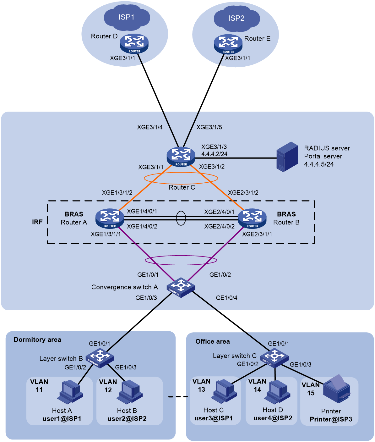
Table 7 IP planning table
|
Device |
Interface |
IP address |
Device |
Interface |
IP address |
|
RADIUS server |
- |
4.4.4.5/24 |
IRF (BRAS) |
RAGG1.1 |
- |
|
Portal server |
- |
4.4.4.5/24 |
RAGG1023 |
100.1.1.1/24 |
|
|
Router C |
RAGG1023 |
100.1.1.2/24 |
XGE1/3/1/1 |
- |
|
|
XGE3/1/1 |
- |
XGE2/3/1/1 |
- |
||
|
XGE3/1/2 |
- |
XGE1/3/1/2 |
- |
||
|
XGE3/1/3 |
4.4.4.2/24 |
XGE2/3/1/2 |
- |
||
|
XGE3/1/4 |
3.3.3.1/24 |
LoopBack1 |
80.1.1.1/32 |
||
|
XGE3/1/5 |
5.5.5.1/24 |
Printer |
- |
2.1.6.1/24 |
|
|
Router D |
XGE3/1/1 |
3.3.3.2/24 |
Router E |
XGE3/1/1 |
5.5.5.2/24 |
Analysis
· To avoid the impact of a single point of failure in member devices on normal traffic forwarding, configure multichassis aggregate interfaces on the IRF fabric for traffic forwarding.
· To minimize the impact of IRF fabric split on services, configure Link Aggregation Control Protocol (LACP) Multiple Active Detection (MAD) on the IRF fabric. You need to configure LACP MAD for only one aggregate group. The intermediate device used for LACP MAD must be an H3C device and its software version used must support recognizing and processing link aggregation control protocol data units (LACPDUs) carrying active IDs. In this example, Switch A is used as the intermediate device for LACP MAD.
· To disable printers in the office area from accessing the Internet, filter the packets sent out of XGE 3/1/4 and XGE 3/1/5 on Router C.
Procedure
Configure IP addresses and routes
1. Configure Router C:
# Assign IPv4 address 4.4.4.2/24 to Ten-GigabitEthernet 3/1/3 on Router C, which connects to the server.
<RouterC> system-view
[RouterC] interface ten-gigabitethernet 3/1/3
[RouterC-Ten-GigabitEthernet3/1/3] ip address 4.4.4.2 24
[RouterC-Ten-GigabitEthernet3/1/3] quit
# Assign IPv4 address 3.3.3.1/24 to Ten-GigabitEthernet 3/1/4 on Router C.
[RouterC] interface ten-gigabitethernet 3/1/4
[RouterC-Ten-GigabitEthernet3/1/4] ip address 3.3.3.1 24
[RouterC-Ten-GigabitEthernet3/1/4] quit
# Assign IPv4 address 5.5.5.1/24 to Ten-GigabitEthernet 3/1/5 on Router C.
[RouterC] interface ten-gigabitethernet 3/1/5
[RouterC-Ten-GigabitEthernet3/1/5] ip address 5.5.5.1 24
[RouterC-Ten-GigabitEthernet3/1/5] quit
# Configure the static route from Router C to users.
[RouterC] ip route-static 2.1.0.0 16 100.1.1.1
# Configure the static route from Router C to ISP1.
[RouterC] ip route-static 0.0.0.0 0 3.3.3.2
# Configure the static route from Router C to ISP2.
[RouterC] ip route-static 0.0.0.0 0 5.5.5.2
Set up an IRF fabric
1. Configure Router A and Router B to form an IRF fabric:
# Configure member ID 1 for Router A. Create IRF port 2, and bind it to physical interfaces Ten-GigabitEthernet 4/0/1 and Ten-GigabitEthernet 4/0/2.
<RouterA> system-view
[RouterA] irf member 1 priority 2
[RouterA] interface ten-gigabitethernet 4/0/1
[RouterA-Ten-GigabitEthernet4/0/1] port link-mode bridge
[RouterA-Ten-GigabitEthernet4/0/1] quit
[RouterA] interface ten-gigabitethernet 4/0/2
[RouterA-Ten-GigabitEthernet4/0/2] port link-mode bridge
[RouterA-Ten-GigabitEthernet4/0/2] quit
[RouterA] irf-port 2
[RouterA-irf-port2] port group interface ten-gigabitethernet 4/0/1
[RouterA-irf-port2] port group interface ten-gigabitethernet 4/0/2
[RouterA-irf-port2] quit
# Save the current configuration into the next startup configuration file.
[RouterA] quit
<RouterA> save
# Enable IRF mode.
<RouterA> system-view
[RouterA] chassis convert mode irf
The device will switch to IRF mode and reboot. Continue?[Y/N]:y
You are recommended to save the current running configuration and specify the configuration file for the next startup. Now save the running configuration to the next-startup configuration file? [Y/N]:y
Please input the file name(*.cfg)[cfa0:/test.cfg]
(To leave the existing filename unchanged, press the enter key):
cfa0:/test.cfg exists, overwrite? [Y/N]:y
Validating file. Please wait...
Saved the current configuration to mainboard device successfully.
Do you want to convert the content of the next startup configuration file cfa0:/test.cfg to make it available in IRF mode? [Y/N]:y
Now rebooting, please wait...
After reboot, Router A forms an IRF fabric with only one member device.
# Configure member ID 2 for Router B. Create IRF port 1, and bind it to physical interfaces Ten-GigabitEthernet 4/0/1 and Ten-GigabitEthernet 4/0/2.
<RouterB> system-view
[RouterB] irf member 2 priority 1
[RouterB] interface ten-gigabitethernet 4/0/1
[RouterB-Ten-GigabitEthernet4/0/1] port link-mode bridge
[RouterB-Ten-GigabitEthernet4/0/1] quit
[RouterB] interface ten-gigabitethernet 4/0/2
[RouterB-Ten-GigabitEthernet4/0/2] port link-mode bridge
[RouterB-Ten-GigabitEthernet4/0/2] quit
[RouterB] irf-port 1
[RouterB-irf-port1] port group interface ten-gigabitethernet 4/0/1
[RouterB-irf-port1] port group interface ten-gigabitethernet 4/0/2
[RouterB-irf-port1] quit
# Save the current configuration into the next startup configuration file.
[RouterB] quit
<RouterB> save
# Enable IRF mode.
<RouterB> system-view
[RouterB] chassis convert mode irf
The device will switch to IRF mode and reboot. Continue?[Y/N]:y
You are recommended to save the current running configuration and specify the configuration file for the next startup. Now save the running configuration to the next-startup configuration file? [Y/N]:y
Please input the file name(*.cfg)[cfa0:/test.cfg]
(To leave the existing filename unchanged, press the enter key):
cfa0:/test.cfg exists, overwrite? [Y/N]:y
Validating file. Please wait...
Saved the current configuration to mainboard device successfully.
Do you want to convert the content of the next startup configuration file cfa0:/test.cfg to make it available in IRF mode? [Y/N]:y
Now rebooting, please wait...
After reboot, Router B forms an IRF fabric with Router A.
2. Configure downlink services of the IRF fabric:
a. Configure LACP MAD:
|
|
NOTE: In this example, Router A acts as the master member in the IRF fabric and acts as the BRAS in the IPoE configuration. For ease of understanding, Router A is referred to as IRF in the IRF fabric configuration section and BRAS in the IPoE configuration section. |
After the IRF fabric is set up, you can configure various service modules. Once the IRF fabric is set up, you can log in to any member device for configuration. The default device name is the name of the master member device, which is Router A in this example.
# Create a dynamic aggregation group numbered 1 for connecting to Switch A and enable LACP MAD.
<IRF> system-view
[IRF] interface route-aggregation 1
[IRF-Route-Aggregation1] link-aggregation mode dynamic
[IRF-Route-Aggregation1] mad enable
You need to assign a domain ID (range: 0-4294967295)
[Current domain is: 0]:
The assigned domain ID is: 0
MAD LACP only enable on dynamic aggregation interface.
[IRF-Route-Aggregation1] quit
# Assign the interfaces connecting to Switch A to aggregation group 1.
[IRF] interface ten-gigabitethernet 1/3/1/1
[IRF-Ten-GigabitEthernet1/3/1/1] port link-aggregation group 1
[IRF-Ten-GigabitEthernet1/3/1/1] quit
[IRF] interface ten-gigabitethernet 2/3/1/1
[IRF-Ten-GigabitEthernet2/3/1/1] port link-aggregation group 1
[IRF-Ten-GigabitEthernet2/3/1/1] quit
b. Configure Switch A:
# Create a dynamic aggregation group numbered 1 for connecting to the IRF fabric. This aggregation group is also used for LACP MAD.
<SwitchA> system-view
[SwitchA] interface bridge-aggregation 1
[SwitchA-Bridge-Aggregation1] link-aggregation mode dynamic
[SwitchA-Bridge-Aggregation1] quit
# Assign the interfaces connecting to the IRF fabric to aggregation group 1.
[SwitchA] interface gigabitethernet 1/0/1
[SwitchA-GigabitEthernet1/0/1] port link-aggregation group 1
[SwitchA-GigabitEthernet1/0/1] quit
[SwitchA] interface gigabitethernet 1/0/2
[SwitchA-GigabitEthernet1/0/2] port link-aggregation group 1
[SwitchA-GigabitEthernet1/0/2] quit
3. Configure uplink services of the IRF fabric:
a. Configure an aggregation group on the IRF fabric:
# Create a dynamic aggregation group numbered 1023 for connecting to border router Router C. Assign IP address 100.1.1.1/24 to the aggregate interface.
[IRF] interface route-aggregation 1023
[IRF-Route-Aggregation1023] link-aggregation mode dynamic
[IRF-Route-Aggregation1023] ip address 100.1.1.1 24
[IRF-Route-Aggregation1023] quit
# Assign the interfaces connecting to Router C to aggregation group 1023.
[IRF] interface ten-gigabitethernet 1/3/1/2
[IRF-Ten-GigabitEthernet1/3/1/2] port link-aggregation group 1023
[IRF-Ten-GigabitEthernet1/3/1/2] quit
[IRF] interface ten-gigabitethernet 2/3/1/2
[IRF-Ten-GigabitEthernet2/3/1/2] port link-aggregation group 1023
[IRF-Ten-GigabitEthernet2/3/1/2] quit
# Configure a static default route to Router C for accessing the servers and ISPs.
[IRF] ip route-static 0.0.0.0 24 100.1.1.2
b. Configure Router C:
|
|
NOTE: The section only covers the configuration for connecting to the IRF fabric and does not describe the routing protocol used for the external network. |
# Create a dynamic aggregation group numbered 1023 for connecting to the IRF fabric. Assign IP address 100.1.1.2/24 to the aggregate interface.
<RouterC> system-view
[RouterC] interface route-aggregation 1023
[RouterC-Route-Aggregation1023] link-aggregation mode dynamic
[RouterC-Route-Aggregation1023] ip address 100.1.1.2 24
[RouterC-Route-Aggregation1023] quit
# Assign the interfaces connecting to the IRF fabric to aggregation group 1023.
[RouterC] interface ten-gigabitethernet 3/1/1
[RouterC-Ten-GigabitEthernet3/1/1] port link-aggregation group 1023
[RouterC-Ten-GigabitEthernet3/1/1] quit
[RouterC] interface ten-gigabitethernet 3/1/2
[RouterC-Ten-GigabitEthernet3/1/2] port link-aggregation group 1023
[RouterC-Ten-GigabitEthernet3/1/2] quit
Configure BRAS
1. Configure the address pools:
# Create address pool pool1, and enter its view.
[BRAS] dhcp enable
# Enable the DHCP server to return a DHCP-NAK message if the client notions of their IP addresses are incorrect.
[BRAS] dhcp server request-ip-address check
[BRAS] ip pool pool1 bas local
[BRAS-ip-pool-pool1] gateway 2.1.1.1 16
[BRAS-ip-pool-pool1] dns-list 8.8.8.8
[BRAS-ip-pool-pool1] quit
[BRAS] dhcp server forbidden-ip 2.1.0.0 2.1.255.255
2. Create ISP domain isp3, and enter its view.
[BRAS] domain name isp3
3. Configure IPoE users not to use authentication, authorization, and accounting in ISP domain isp3.
[BRAS-isp-isp3] authentication ipoe none
[BRAS-isp-isp3] authorization ipoe none
[BRAS-isp-isp3] accounting ipoe none
[BRAS-isp-isp3] authorization-attribute ip-pool pool1
[BRAS-isp-isp3] quit
4. Configure static IPoE user access:
# Enable IPoE and configure the Layer 2 access mode.
[BRAS] interface route-aggregation 1.1
[BRAS–Route-Aggregation1.1] ip subscriber l2-connected enable
# Enable unclassified-IP packet initiation.
[BRAS–Route-Aggregation1.1] ip subscriber initiator unclassified-ip enable matching-user
# Enable ARP packet initiation.
[BRAS–Route-Aggregation1.1] ip subscriber initiator arp enable
# Configure an IPv4 static IPoE session with IP address 2.1.6.1 and ISP domain isp3 for the printer in the office area.
[BRAS–Route-Aggregation1.1] quit
[BRAS] ip subscriber session static ip 2.1.6.1 mac 000c-29b6-c756 domain isp3 interface route-aggregation 1.1 vlan 15 request-online gateway ip 2.1.1.1
5. Configure VLAN termination:
# Enable user VLAN dot1q termination on the subinterface.
[BRAS] interface route-aggregation 1.1
[BRAS-Route-Aggregation1.1] user-vlan dot1q vid 11 to 15
# Enable the interface to send broadcast and multicast packets
[BRAS-Route-Aggregation1.1] vlan-termination broadcast enable
# (Optional.) Enable both local proxy ARP and common proxy ARP on the interface (to facilitate communication between users).
[BRAS-Route-Aggregation1.1] local-proxy-arp enable
[BRAS-Route-Aggregation1.1] proxy-arp enable
[BRAS–Route-Aggregation1.1] quit
6. Configure attack defense:
¡ Configure source MAC-based ARP attack detection:
# Enable the source MAC-based ARP attack detection feature and specify the filter handling method.
[BRAS] arp source-mac filter
# Set the check interval for source MAC-based ARP attack detection to 5 seconds.
[BRAS] arp source-mac check-interval 5
# Set the threshold for source MAC-based ARP attack detection to 30.
[BRAS] arp source-mac threshold 30
# Set the aging time for ARP attack entries to 300 seconds.
[BRAS] arp source-mac aging-time 300
¡ Configure DHCP flood attack protection:
# Enable DHCP flood attack protection on interface Route-Aggregation1.1.
[BRAS] interface route-aggregation 1.1
[BRAS-Route-Aggregation1.1] dhcp flood-protection enable
[BRAS–Route-Aggregation1.1] quit
# Configure the device to allow a maximum of 30 DHCP packets per 10000 milliseconds from each DHCP client.
[BRAS] dhcp flood-protection threshold 30 10000
# Set the DHCP flood attack entry aging time to 300 seconds.
[BRAS] dhcp flood-protection aging-time 300
¡ Enable ICMP fast reply:
[BRAS] ip icmp fast-reply enable
¡ Configure TCP SYN flood attack prevention:
# Enable flow-based TCP SYN flood attack prevention.
[BRAS] tcp anti-syn-flood flow-based enable
# Set the check interval to 20 seconds for flow-based TCP SYN flood attack prevention.
[BRAS] tcp anti-syn-flood flow-based check-interval 20
# Set the threshold to 2000 for triggering flow-based TCP SYN flood attack prevention.
[BRAS] tcp anti-syn-flood flow-based threshold 2000
# Set the flow-based TCP SYN flood attack prevention duration to 5 minutes.
[BRAS] tcp anti-syn-flood flow-based duration 5
7. Configure Router C:
# Configure ACL 3002 to match packets from the printer.
[RouterC] acl advanced 3002
[RouterC-acl-ipv4-adv-3002] rule 5 deny ip source 2.1.6.1 0
[RouterC-acl-ipv4-adv-3002] quit
# Apply ACL 3002 to filter the outgoing packets on Ten- GigabitEthernet 3/1/4.
[RouterC] interface ten-gigabitethernet 3/1/4
[RouterC–Ten-GigabitEthernet3/1/4] packet-filter 3002 outbound
[RouterC–Ten-GigabitEthernet3/1/4] quit
# Apply ACL 3002 to filter the outgoing packets on GigabitEthernet 3/1/5.
[RouterC] interface ten-gigabitethernet 3/1/5
[RouterC–Ten-GigabitEthernet3/1/5] packet-filter 3002 outbound
[RouterC–Ten-GigabitEthernet3/1/5] quit
Verifying the configuration
# View detailed information about the static IPoE user for the printer.
[BRAS] display access-user interface route-aggregation 1.1
UserID Interface IP address MAC address S-/C-VLAN
Username Access type
IPv6 address
0x5c RAGG1.1 2.1.6.1 000c-29a6-b656 15/-
2.1.6.1 L2 IPoE static
-
Configuration files
· Router C:
#
interface Route-Aggregation1023
ip address 100.1.1.2 255.255.255.0
link-aggregation mode dynamic
#
interface Ten-GigabitEthernet3/1/1
port link-aggregation group 1023
#
interface Ten-GigabitEthernet3/1/2
port link-aggregation group 1023
#
interface Ten-GigabitEthernet3/1/3
ip address 4.4.4.2 255.255.255.0
#
interface Ten-GigabitEthernet3/1/4
port link-mode route
ip address 3.3.3.1 255.255.255.0
packet-filter 3002 outbound
#
interface Ten-GigabitEthernet3/1/5
port link-mode route
ip address 5.5.5.1 255.255.255.0
packet-filter 3002 outbound
#
ip route-static 0.0.0.0 0 3.3.3.2
ip route-static 0.0.0.0 0 5.5.5.2
ip route-static 2.1.0.0 16 100.1.1.1
#
acl advanced 3002
rule 5 deny ip source 2.1.6.1 0
#
· IRF (BRAS):
#
irf mac-address persistent always
irf auto-update enable
irf auto-merge enable
undo irf link-delay
irf member 1 priority 2
irf member 2 priority 1
#
irf-port 1/2
port group interface Ten-GigabitEthernet1/4/0/1 mode enhanced
port group interface Ten-GigabitEthernet1/4/0/2 mode enhanced
#
irf-port 2/1
port group interface Ten-GigabitEthernet2/4/0/1 mode enhanced
port group interface Ten-GigabitEthernet2/4/0/2 mode enhanced
#
dhcp enable
dhcp server request-ip-address check
dhcp server forbidden-ip 2.1.0.0 2.1.255.255
#
ip pool pool1 bas local
gateway 2.1.1.1 mask 255.255.0.0
dns-list 8.8.8.8
#
ip subscriber session static ip 2.1.6.1 mac 000c-29b6-c756 domain isp3 interface Route-Aggregation1.1 vlan 15 request-online gateway ip 2.1.1.1
#
interface Route-Aggregation1
link-aggregation mode dynamic
mad enable
#
interface Route-Aggregation1.1
local-proxy-arp enable
proxy-arp enable
user-vlan dot1q vid 11 to 15
vlan-termination broadcast enable
dhcp flood-protection enable
ip subscriber l2-connected enable
ip subscriber initiator unclassified-ip enable matching-user
ip subscriber initiator arp enable
#
interface Route-Aggregation1023
ip address 100.1.1.1 255.255.255.0
link-aggregation mode dynamic
#
interface Ten-GigabitEthernet1/3/1/1
port link-aggregation group 1
#
interface Ten-GigabitEthernet2/3/1/1
port link-aggregation group 1
#
interface Ten-GigabitEthernet1/3/1/2
port link-aggregation group 1023
#
interface Ten-GigabitEthernet2/3/1/2
port link-aggregation group 1023
#
ip route-static 0.0.0.0 24 100.1.1.2
#
domain name isp3
authorization-attribute ip-pool pool1
authentication ipoe none
authorization ipoe none
accounting ipoe none
#
tcp anti-syn-flood flow-based enable
tcp anti-syn-flood flow-based threshold 2000
tcp anti-syn-flood flow-based check-interval 20
#
dhcp flood-protection threshold 30 10000
#
ip icmp fast-reply enable
#
arp source-mac filter
#
RADIUS proxy configuration example (with BRASs as IPoE access points and AC as wireless 802.1X access point) (Layer 2)
The authentication information of wired and wireless users is stored on different devices when the following conditions are met:
· The BRASs are enabled with IPoE authentication to provide access authentication service for users.
· The AC is attached to the BRAS side to perform 802.1X authentication on wireless clients.
To simplify user information management and unify user access policies, enable the Remote Authentication Dial-In User Service (RADIUS) proxy feature on the BRASs and specify the AC as a RADIUS client.
On a RADIUS proxy network, you can attach the AC to the BRAS device side or the switch side under the BRASs. When you attach the AC to the BRAS side, you can deploy Layer 3 devices between the AC and BRASs. In this example, the AC is attached to the switch side.
Network configuration
As shown in Figure 37, Router A and Router B are two broadband remote access servers (BRASs) of a school, and they form an IRF fabric to provide IPoE access services for school users. The AC is attached to Switch B side to perform 802.1X authentication on wireless clients. Configure the network to meet the following requirements:
· Use BRASs as RADIUS proxies to perform authentication, authorization, and accounting for wireless 802.1X users.
· Configure the BRASs and the RADIUS server to use a shared key of 123456 for secure RADIUS communication. The authentication and accounting ports are 1812 and 1813, respectively.
· Enable IPoE on Layer 3 aggregate subinterface 1.2. Configure the BRASs to use Layer 3 aggregate subinterface 1.3 to communicate with the AC as RADIUS proxies.
· Configure the AC and the RADIUS proxies to use a shared key of 123456 for secure RADIUS communication. The authentication and accounting ports are 2016 and 2017, respectively.
· The BRASs request IPv4 addresses from the remote DHCP server as the DHCP relay agent. Configure ND prefix pools on the BRASs to assign ND prefixes to users for IPv6 address generation.
· Configure the DHCP server to assign IP addresses to the APs and wireless clients.
· Configure the AP to forward the data traffic from the wireless clients directly.
· Configure the wireless clients and BRASs to use inner VLAN 20 and outer VLAN 10 as service VLANs to communicate with each other.
· Configure the AC and BRASs to use inner VLAN 50 and outer VLAN 10 as management VLANs to communicate with each other.
· Configure the APs and AC to use VLAN 50 as a management VLAN to establish CAPWAP tunnels.
· Use a server with Srun software installed as a RADIUS server.
· Configure basic attack protection features for some protocol packets (for example, ARP and DHCP) on BRASs to prevent illegal packets from impacting the network.
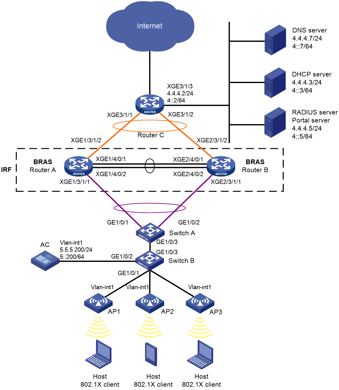
Table 8 IP planning table
|
Device |
Interface |
IP address |
Device |
Interface |
IP address |
|
DNS server |
N/A |
4.4.4.7/24 4::7/64 |
IRF (BRAS) |
RAGG1.1 |
N/A |
|
DHCP server |
N/A |
4.4.4.3/24 4::3/64 |
|
RAGG1.2 (IPoE) |
N/A |
|
RADIUS server & portal server |
|
4.4.4.5/24 4::5/64 |
|
RAGG1.3 (RADIUS proxy) |
5.5.5.254/24 5::254/64 |
|
Router C |
RAGG1023 |
100.1.1.2/24 100::2/64 |
|
RAGG1023 |
100.1.1.1/24 100::1/64 |
|
XGE3/1/1 |
N/A |
|
XGE1/3/1/1 |
N/A |
|
|
XGE3/1/2 |
N/A |
|
XGE2/3/1/1 |
N/A |
|
|
XGE3/1/3 |
4.4.4.2/24 4::2/64 |
|
XGE1/3/1/2 |
N/A |
|
|
AC |
Vlan-int50 |
5.5.5.200/24 5::200/64 |
|
XGE2/3/1/2 |
N/A |
|
|
|
|
|
LoopBack1 |
80.1.1.1/32 80::1/128 |
Analysis
· To avoid the impact of a single point of failure in member devices on normal traffic forwarding, configure multichassis aggregate interfaces on the IRF fabric for traffic forwarding.
· To minimize the impact of IRF fabric split on services, configure Link Aggregation Control Protocol (LACP) Multiple Active Detection (MAD) on the IRF fabric. You need to configure LACP MAD for only one aggregate group. The intermediate device used for LACP MAD must be an H3C device and its software version used must support recognizing and processing link aggregation control protocol data units (LACPDUs) carrying active IDs. In this example, Switch A is used as the intermediate device for LACP MAD.
· Enable IPoE and configure the Layer 2 access mode on the BRASs and configure RADIUS proxy authentication and authorization for IPoE users. Configure the accounting methods if required.
· Specify the BRAS devices as the authentication and accounting servers.
· Configure the DHCP server to send the AC's IP address to the APs through DHCP Option 43.
· Configure the ISP domain not to perform accounting for LAN users on the AC.
· Execute the client forwarding-location command in service template view on the AC to configure the AC or APs to forward client data traffic. (This example configures the APs to forward client data traffic.) For wireless application, DHCP packets are data packets and comply with the following forwarding principles:
¡ If you configure the AC to forward client data (centralized forwarding), data packets from clients are transparently transmitted by the APs to the AC over the CAPWAP tunnels, and the AC forwards the data packets. To have the configuration take effect, make sure the client traffic forwarding feature is enabled. To enable client traffic forwarding, use the wlan client forwarding enable command
¡ If you configure the APs to forward client data (local forwarding), the APs forward the data packets from clients directly.
· To have the APs forward client data traffic in service VLAN 20 on GigabitEthernet 1/0/1, edit a .txt configuration file to add the port to VLAN 20 and upload the file to the AC.
Restrictions and guidelines
The DHCP server in this configuration is simulated by a device. As a best practice, use a dedicated DHCP server in actual applications.
This configuration example uses a DHCPv4 server to assign IPv4 addresses to endpoints and ND RS method to assign IPv6 addresses to endpoints. Once users have passed the authentication, they can come online in both the IPv4 and IPv6 protocol stacks.
On a single-VLAN or dual-VLAN (QinQ) network, the Layer 1 VLAN of a wireless client can be added on an AP or on the switch connected to the AP. The outer VLAN can only be added on the switch connected to the AP by using QinQ. To directly add the Layer 1 VLAN on an AP, execute the vlan command in service template view on the AC.
For example:
[AC] wlan service-template 1x
[AC-wlan-st-1x] vlan 20 //Service VLAN to which a wireless client belongs after it connects to the AP. Make sure the interface that connects to the switch on the AP is assigned to the VLAN.
Procedure
Configure IP addresses and routes
# Assign IPv4 address 4.4.4.2/24 and IPv6 address 4::2/64 to Ten-GigabitEthernet 3/1/3 on Router C.
<RouterC> system-view
[RouterC] interface ten-gigabitethernet 3/1/3
[RouterC-Ten-GigabitEthernet3/1/3] ip address 4.4.4.2 24
[RouterC-Ten-GigabitEthernet3/1/3] ipv6 address 4::2 64
[RouterC-Ten-GigabitEthernet3/1/3] quit
# Configure the static routes from Router C to users.
[RouterC] ip route-static 192.168.0.0 24 100.1.1.1
[RouterC] ipv6 route-static 192:: 64 100::1
# Configure the static routes from Router C to the AC.
[RouterC] ip route-static 5.5.5.0 24 100.1.1.1
[RouterC] ipv6 route-static 5:: 64 100::1
Configure the DHCP server
1. Enable the DHCP service:
# Enable DHCP.
<DHCP> system-view
[DHCP] dhcp enable
# Enable the DHCP server to return a DHCP-NAK message if the client notions of their IP addresses are incorrect.
[DHCP] dhcp server request-ip-address check
2. Configure the DHCP address pool used by the wireless 802.1X clients:
# Create IP address pool pool1 and enter its view.
[DHCP] ip pool pool1
# Specify primary subnet 192.168.0.0/24 for dynamic allocation in the address pool and specify DNS server address 4.4.4.7 in the address pool.
[DHCP-ip-pool-pool1] network 192.168.0.0 24
[DHCP-ip-pool-pool1] dns-list 4.4.4.7
# Specify gateway address 192.168.0.1.
[DHCP-ip-pool-pool1] gateway-list 192.168.0.1
# Exclude gateway address 192.168.0.1 from dynamic allocation.
[DHCP-ip-pool-pool1] forbidden-ip 192.168.0.1
[DHCP-ip-pool-pool1] quit
# Configure a route. (This example configures a default route. On a live network, configure the route as needed.)
[DHCP] ip route-static 0.0.0.0 0 4.4.4.2
3. Configure the DHCP address pool used by the APs:
# Create IP address pool pool_ap and enter its view.
[DHCP] ip pool pool_ap
# Specify network segment 5.5.5.0/24 in address pool pool_ap.
[DHCP-ip-pool-pool_ap] network 5.5.5.0 24
# Specify gateway address 5.5.5.254 in address pool pool_ap.
[DHCP-ip-pool-pool_ap] gateway-list 5.5.5.254
# Exclude gateway address 5.5.5.254 and AC's IP address 5.5.5.200 from dynamic allocation in address pool pool_ap.
[DHCP-ip-pool-pool_ap] forbidden-ip 5.5.5.254
[DHCP-ip-pool-pool_ap] forbidden-ip 5.5.5.200
# Configure Option 43 to specify the IP address of the AC in address pool pool_ap. The right-most bytes 050505C8 (5.5.5.200) represent the IP address of the AC.
[DHCP-ip-pool-pool_ap] option 43 hex 8007000001050505C8
[DHCP-ip-pool-pool_ap] quit
# Configure a route. (This example configures a default route. On a live network, configure the route as needed.)
[DHCP] ip route-static 0.0.0.0 0 4.4.4.2
Configure the RADIUS server
The following uses a server with Srun software 4.0.9 installed as an example.
To configure the RADIUS server:
1. Enter http://4.4.4.5:8081 in the address bar of a browser to log in to the server. Add access devices:
# Select Device Management from the navigation tree. Click the Add Device tab. On the tab, click Add.
¡ Set the device name to BRAS.
¡ Set the NAS IP address to the IP address of interface LoopBack1 on the BRAS, 80.1.1.1.
¡ Set the device IP to 4.4.4.5.
¡ Select Huawei, H3C, and Srun Gateways from the NAS type list.
¡ Set the DM port to 3799.
¡ Set the RADIUS key to 123456.
¡ Select No from the whether to drop traffic list.
¡ Select h3c v1.2 from the portal server list.
¡ Set the portal key to 123456.
# Set the RADIUS trust. Select RADIUS from the navigation tree. Click the RADIUS Trust Settings link to enter the RADIUS trust settings page. Click Generate in the upper right corner until the trust is successfully generated. Then, restart the radius process of Srun.
# Click the RADIUS Service Settings tab, and specify the device to carry the ISP domain name in the username sent to the RADIUS server.
2. Enter https://4.4.4.5:8080 in the address bar of a browser to log in to the server. Add users:
a. Navigate to the User Management > Add Users page. Click Add.
b. Add user user1 with account user1 and password pass.
3. For information about deploying other configurations such as control policies and product policies, see the configuration guides for Srun.
Set up an IRF fabric
1. Configure Router A and Router B to form an IRF fabric:
# Configure member ID 1 for Router A. Create IRF port 2, and bind it to physical interfaces Ten-GigabitEthernet 4/0/1 and Ten-GigabitEthernet 4/0/2.
<RouterA> system-view
[RouterA] irf member 1 priority 2
[RouterA] interface ten-gigabitethernet 4/0/1
[RouterA-Ten-GigabitEthernet4/0/1] port link-mode bridge
[RouterA-Ten-GigabitEthernet4/0/1] quit
[RouterA] interface ten-gigabitethernet 4/0/2
[RouterA-Ten-GigabitEthernet4/0/2] port link-mode bridge
[RouterA-Ten-GigabitEthernet4/0/2] quit
[RouterA] irf-port 2
[RouterA-irf-port2] port group interface ten-gigabitethernet 4/0/1
[RouterA-irf-port2] port group interface ten-gigabitethernet 4/0/2
[RouterA-irf-port2] quit
# Save the current configuration into the next startup configuration file.
[RouterA] quit
<RouterA> save
# Enable IRF mode.
<RouterA> system-view
[RouterA] chassis convert mode irf
The device will switch to IRF mode and reboot. Continue?[Y/N]:y
You are recommended to save the current running configuration and specify the configuration file for the next startup. Now save the running configuration to the next-startup configuration file? [Y/N]:y
Please input the file name(*.cfg)[cfa0:/test.cfg]
(To leave the existing filename unchanged, press the enter key):
cfa0:/test.cfg exists, overwrite? [Y/N]:y
Validating file. Please wait...
Saved the current configuration to mainboard device successfully.
Do you want to convert the content of the next startup configuration file cfa0:/test.cfg to make it available in IRF mode? [Y/N]:y
Now rebooting, please wait...
After reboot, Router A forms an IRF fabric with only one member device.
# Configure member ID 2 for Router B. Create IRF port 1, and bind it to physical interfaces Ten-GigabitEthernet 4/0/1 and Ten-GigabitEthernet 4/0/2.
<RouterB> system-view
[RouterB] irf member 2 priority 1
[RouterB] interface ten-gigabitethernet 4/0/1
[RouterB-Ten-GigabitEthernet4/0/1] port link-mode bridge
[RouterB-Ten-GigabitEthernet4/0/1] quit
[RouterB] interface ten-gigabitethernet 4/0/2
[RouterB-Ten-GigabitEthernet4/0/2] port link-mode bridge
[RouterB-Ten-GigabitEthernet4/0/2] quit
[RouterB] irf-port 1
[RouterB-irf-port1] port group interface ten-gigabitethernet 4/0/1
[RouterB-irf-port1] port group interface ten-gigabitethernet 4/0/2
[RouterB-irf-port1] quit
# Save the current configuration into the next startup configuration file.
[RouterB] quit
<RouterB> save
# Enable IRF mode.
<RouterB> system-view
[RouterB] chassis convert mode irf
The device will switch to IRF mode and reboot. Continue?[Y/N]:y
You are recommended to save the current running configuration and specify the configuration file for the next startup. Now save the running configuration to the next-startup configuration file? [Y/N]:y
Please input the file name(*.cfg)[cfa0:/test.cfg]
(To leave the existing filename unchanged, press the enter key):
cfa0:/test.cfg exists, overwrite? [Y/N]:y
Validating file. Please wait...
Saved the current configuration to mainboard device successfully.
Do you want to convert the content of the next startup configuration file cfa0:/test.cfg to make it available in IRF mode? [Y/N]:y
Now rebooting, please wait...
After reboot, Router B forms an IRF fabric with Router A.
2. Configure downlink services of the IRF fabric:
a. Configure LACP MAD:
|
i |
ii NOTE: iii In this example, Router A acts as the master member in the IRF fabric and acts as the BRAS in the IPoE configuration. For ease of understanding, Router A is referred to as IRF in the IRF fabric configuration section and BRAS in the IPoE configuration section. |
After the IRF fabric is set up, you can configure various service modules. Once the IRF fabric is set up, you can log in to any member device for configuration. The default device name is the name of the master member device, which is Router A in this example.
# Create a dynamic aggregation group numbered 1 for connecting to Switch A and enable LACP MAD.
<IRF> system-view
[IRF] interface route-aggregation 1
[IRF-Route-Aggregation1] link-aggregation mode dynamic
[IRF-Route-Aggregation1] mad enable
You need to assign a domain ID (range: 0-4294967295)
[Current domain is: 0]:
The assigned domain ID is: 0
MAD LACP only enable on dynamic aggregation interface.
[IRF-Route-Aggregation1] quit
# Assign the interfaces connecting to Switch A to aggregation group 1.
[IRF] interface ten-gigabitethernet 1/3/1/1
[IRF-Ten-GigabitEthernet1/3/1/1] port link-aggregation group 1
[IRF-Ten-GigabitEthernet1/3/1/1] quit
[IRF] interface ten-gigabitethernet 2/3/1/1
[IRF-Ten-GigabitEthernet2/3/1/1] port link-aggregation group 1
[IRF-Ten-GigabitEthernet2/3/1/1] quit
b. Configure Switch A:
# Create a dynamic aggregation group numbered 1 for connecting to the IRF fabric. This aggregation group is also used for LACP MAD.
<SwitchA> system-view
[SwitchA] interface bridge-aggregation 1
[SwitchA-Bridge-Aggregation1] link-aggregation mode dynamic
[SwitchA-Bridge-Aggregation1] quit
# Assign the interfaces connecting to the IRF fabric to aggregation group 1.
[SwitchA] interface gigabitethernet 1/0/1
[SwitchA-GigabitEthernet1/0/1] port link-aggregation group 1
[SwitchA-GigabitEthernet1/0/1] quit
[SwitchA] interface gigabitethernet 1/0/2
[SwitchA-GigabitEthernet1/0/2] port link-aggregation group 1
[SwitchA-GigabitEthernet1/0/2] quit
3. Configure uplink services of the IRF fabric:
a. Configure an aggregation group on the IRF fabric:
# Create a dynamic aggregation group numbered 1023 for connecting to border router Router C. Assign IPv4 address 100.1.1.1/24 and IPv6 address 100::1/64 to the aggregate interface.
[IRF] interface route-aggregation 1023
[IRF-Route-Aggregation1023] link-aggregation mode dynamic
[IRF-Route-Aggregation1023] ip address 100.1.1.1 24
[IRF-Route-Aggregation1023] ipv6 address 100::1 64
[IRF-Route-Aggregation1023] quit
# Assign the interfaces connecting to Router C to aggregation group 1023.
[IRF] interface ten-gigabitethernet 1/3/1/2
[IRF-Ten-GigabitEthernet1/3/1/2] port link-aggregation group 1023
[IRF-Ten-GigabitEthernet1/3/1/2] quit
[IRF] interface ten-gigabitethernet 2/3/1/2
[IRF-Ten-GigabitEthernet2/3/1/2] port link-aggregation group 1023
[IRF-Ten-GigabitEthernet2/3/1/2] quit
# Configure a static default route to Router C for accessing the servers and Internet.
[IRF] ip route-static 0.0.0.0 0 100.1.1.2
[IRF] ipv6 route-static :: 0 100::2
b. Configure Router C:
|
|
iv NOTE: v The section only covers the configuration for connecting to the IRF fabric and does not describe the routing protocol used for the external network. |
# Create a dynamic aggregation group numbered 1023 for connecting to the IRF fabric. Assign IPv4 address 100.1.1.1/24 and IPv6 address 100::2/64 to the aggregate interface.
<RouterC> system-view
[RouterC] interface route-aggregation 1023
[RouterC-Route-Aggregation1023] link-aggregation mode dynamic
[RouterC-Route-Aggregation1023] ip address 100.1.1.2 24
[RouterC-Route-Aggregation1023] ipv6 address 100::2 64
[RouterC-Route-Aggregation1023] quit
# Assign the interfaces connecting to the IRF fabric to aggregation group 1023.
[RouterC] interface ten-gigabitethernet 3/1/1
[RouterC-Ten-GigabitEthernet3/1/1] port link-aggregation group 1023
[RouterC-Ten-GigabitEthernet3/1/1] quit
[RouterC] interface ten-gigabitethernet 3/1/2
[RouterC-Ten-GigabitEthernet3/1/2] port link-aggregation group 1023
[RouterC-Ten-GigabitEthernet3/1/2] quit
Configure BRAS
1. (IPv4) Configure the DHCP relay agent:
# Enable DHCP globally.
[BRAS] dhcp enable
# For the wireless clients, create DHCP relay address pool pool1, and specify the gateway address and the DHCP server for the address pool.
[BRAS] ip pool pool1 bas remote
[BRAS-ip-pool-pool1] gateway 192.168.0.1 24
[BRAS-ip-pool-pool1] remote-server 4.4.4.3
[BRAS-ip-pool-pool1] quit
# For the APs, enable the DHCPv4 relay agent on Route-Aggregation 1.3.
[BRAS] interface route-aggregation 1.3
[BRAS–Route-Aggregation1.3] dhcp select relay
[BRAS–Route-Aggregation1.3] dhcp relay server-address 4.4.4.3
[BRAS–Route-Aggregation1.3] quit
2. Configure the ND prefix pool:
# Configure prefix pool 1 that contains prefix 10::/32 and specify the length of prefixes to be assigned as 64. Prefix pool 1 can assign 4294967296 prefixes in the range of 10::/64 to 10:0:FFFF:FFFF::/64.
[BRAS] ipv6 dhcp prefix-pool 1 prefix 10::/32 assign-len 64
# Create IPv6 address pool ndra, and reference prefix pool 1.
[BRAS] ipv6 pool ndra
[BRAS-ipv6-pool-ndra] prefix-pool 1 export-route
# Enable IPv6 prefix reservation in IPv6 address pool ndra.
[BRAS-ipv6-pool-ndra] reserve expired-pd enable
[BRAS-ipv6-pool-ndra] quit
3. Configure a RADIUS scheme:
# Create RADIUS scheme rs1, and enter its view.
[BRAS] radius scheme rs1
# Configure the primary authentication and accounting servers and the keys for secure RADIUS authentication and accounting communication for the RADIUS scheme.
[BRAS-radius-rs1] primary authentication 4.4.4.5
[BRAS-radius-rs1] primary accounting 4.4.4.5
[BRAS-radius-rs1] key authentication simple 123456
[BRAS-radius-rs1] key accounting simple 123456
# Exclude the ISP name from the username sent to the RADIUS server.
[BRAS-radius-rs1] user-name-format without-domain
# Specify source IP address 80.1.1.1 for outgoing RADIUS packets.
[BRAS-radius-rs1] nas-ip 80.1.1.1
[BRAS-radius-rs1] quit
# Specify the DAC as 4.4.4.5. Set the shared key to 123456 in plaintext form for secure communication between the DAS and DAC. Make sure the plaintext key is the same on both ends.
[BRAS] radius dynamic-author server
[BRAS-radius-da-server] client ip 4.4.4.5 key simple 123456
[BRAS-radius-da-server] quit
4. Configure RADIUS proxy:
# Enable the RADIUS proxy feature and enter RADIUS proxy view.
[BRAS] radius-proxy
# Specify the RADIUS client (AC) at 5.5.5.200 for the RADIUS proxy and set the shared key to 123456 in plaintext form for secure RADIUS communication with the RADIUS client. Set the authentication port to 2016 and the accounting port to 2017 for communication with the RADIUS client. Configure the RADIUS proxy to use the RADIUS servers in RADIUS scheme rs1 for the users from the RADIUS client.
[BRAS-radius-proxy] client ip 5.5.5.200 radius-scheme rs1 key simple 123456 authentication-port 2016 accounting-port 2017
|
|
If multiple ACs exist, use the client ip command to distribute client IP addresses to different RADIUS schemes for load balancing. |
5. Configure the authentication domain:
# Create an ISP domain named 1X and enter its view.
[BRAS] domain name 1X
# Configure the authorized IP address pool and ND prefix pool in ISP domain 1X.
[BRAS-isp-1X] authorization-attribute ip-pool pool1
[BRAS-isp-1X] authorization-attribute ipv6-nd-prefix-pool ndra
# Configure the ISP domain to use RADIUS proxy for IPoE user authentication and authorization.
[BRAS-isp-1X] authentication ipoe radius-proxy
[BRAS-isp-1X] authorization ipoe radius-proxy
# Configure the ISP domain to use RADIUS scheme rs1 for IPoE user accounting.
[BRAS-isp-1X] accounting ipoe radius-scheme rs1
[BRAS-isp-1X] quit
6. Configure IPoE:
# Enable IPoE and configure the Layer 2 access mode.
[BRAS] interface route-aggregation 1.2
[BRAS–Route-Aggregation1.2] ip subscriber l2-connected enable
# Configure packet initiation methods.
[BRAS–Route-Aggregation1.2] ip subscriber initiator arp enable
[BRAS–Route-Aggregation1.2] ip subscriber initiator unclassified-ip enable matching-user
[BRAS–Route-Aggregation1.2] ip subscriber initiator unclassified-ipv6 enable matching-user
[BRAS–Route-Aggregation1.2] ip subscriber initiator nsna enable
[BRAS–Route-Aggregation1.2] ip subscriber initiator ndrs enable
# Configure the authentication domain for IPoE users.
[BRAS–Route-Aggregation1.2] ip subscriber dhcp domain 1x
[BRAS–Route-Aggregation1.2] ip subscriber ndrs domain 1x
# Configure the DHCP and DHCPv6 servers to use the fast-renew method for roaming clients.
[BRAS–Route-Aggregation1.2] dhcp session-mismatch action fast-renew
[BRAS–Route-Aggregation1.2] ipv6 dhcp session-mismatch action fast-renew
# Enable the DHCP relay agent on interface Route-Aggregation 1.2.
[BRAS–Route-Aggregation1.2] dhcp select relay
# Enable the DHCPv6 server on interface Route-Aggregation 1.2.
[BRAS–Route-Aggregation1.2] ipv6 dhcp select server
# Disable RA message suppression on interface Route-Aggregation 1.2 and configure the interface to automatically generate a link-local address. The IPv6 link-local address is to be used as the gateway of users.
[BRAS–Route-Aggregation1.2] undo ipv6 nd ra halt
[BRAS–Route-Aggregation1.2] ipv6 address auto link-local
# Enable user VLAN QinQ termination on interface Route-Aggregation 1.2. Configure the interface to terminate VLAN-tagged packets with Layer 1 VLAN ID 10 and Layer 2 VLAN ID 20.
[BRAS–Route-Aggregation1.2] user-vlan dot1q vid 10 second-dot1q 20
[BRAS–Route-Aggregation1.2] quit
7. Configure VLAN termination for RADIUS proxy:
# Enable user VLAN QinQ termination on interface Route-Aggregation 1.3. Configure the interface to terminate VLAN-tagged packets with Layer 1 VLAN ID 10 and Layer 2 VLAN ID 50.
[BRAS] interface route-aggregation 1.3
[BRAS–Route-Aggregation1.3] vlan-type dot1q vid 10 second-dot1q 50
[BRAS–Route-Aggregation1.3] quit
8. Configure attack defense:
¡ Configure source MAC-based ARP attack detection:
# Enable the source MAC-based ARP attack detection feature and specify the filter handling method.
[BRAS] arp source-mac filter
# Set the check interval for source MAC-based ARP attack detection to 5 seconds.
[BRAS] arp source-mac check-interval 5
# Set the threshold for source MAC-based ARP attack detection to 30.
[BRAS] arp source-mac threshold 30
# Set the aging time for ARP attack entries to 300 seconds.
[BRAS] arp source-mac aging-time 300
¡ Configure source MAC-based ND attack detection:
# Enable the source MAC-based ND attack detection feature and specify the filter handling method.
[BRAS] ipv6 nd source-mac filter
# Set the check interval for source MAC-based ND attack detection to 5 seconds.
[BRAS] ipv6 nd source-mac check-interval 5
# Set the threshold for source MAC-based ND attack detection to 30.
[BRAS] ipv6 nd source-mac threshold 30
# Set the aging time for ND attack entries to 300 seconds.
[BRAS] ipv6 nd source-mac aging-time 300
¡ Configure DHCP flood attack protection:
# Enable DHCP flood attack protection on interface Route-Aggregation 1.2.
[BRAS] interface route-aggregation 1.2
[BRAS-Route-Aggregation1.2] dhcp flood-protection enable
[BRAS–Route-Aggregation1.2] quit
# Configure the device to allow a maximum of 30 DHCP packets per 10000 milliseconds from each DHCP client.
[BRAS] dhcp flood-protection threshold 30 10000
# Set the DHCP flood attack entry aging time to 300 seconds.
[BRAS] dhcp flood-protection aging-time 300
¡ Configure DHCPv6 flood attack protection:
# Enable DHCPv6 flood attack protection on interface Route-Aggregation 1.2.
[BRAS] interface route-aggregation 1.2
[BRAS-Route-Aggregation1.2] ipv6 dhcp flood-protection enable
[BRAS-Route-Aggregation1.2] quit
# Configure the device to allow a maximum of 30 DHCPv6 packets per 10000 milliseconds from each DHCPv6 client.
[BRAS] ipv6 dhcp flood-protection threshold 30 10000
# Set the DHCPv6 flood attack entry aging time to 300 seconds.
[BRAS] ipv6 dhcp flood-protection aging-time 300
¡ Enable ICMP and ICMPv6 fast reply.
[BRAS] ip icmp fast-reply enable
[BRAS] ipv6 icmpv6 fast-reply enable
¡ Configure TCP SYN flood attack prevention:
# Enable flow-based TCP SYN flood attack prevention.
[BRAS] tcp anti-syn-flood flow-based enable
# Set the check interval to 20 seconds for flow-based TCP SYN flood attack prevention.
[BRAS] tcp anti-syn-flood flow-based check-interval 20
# Set the threshold to 2000 for triggering flow-based TCP SYN flood attack prevention.
[BRAS] tcp anti-syn-flood flow-based threshold 2000
# Set the flow-based TCP SYN flood attack prevention duration to 5 minutes.
[BRAS] tcp anti-syn-flood flow-based duration 5
¡ Configure HTTP/HTTPS attack defense:
# Enable destination IP-based IPoE HTTP/HTTPS attack defense.
[BRAS] ip subscriber http-defense destination-ip enable
# Trigger attack defense when the total number of HTTP/HTTPS packets sent to the same destination IP address within 300 seconds reaches 6000.
[BRAS] ip subscriber http-defense destination-ip threshold 6000 interval 300
¡ Enable HTTP packet fast reply on interface Route-Aggregation 1.2.
[BRAS] interface route-aggregation 1.2
[BRAS-Route-Aggregation1.2] ip subscriber http-fast-reply enable
[BRAS-Route-Aggregation1.2] quit
Edit the AP configuration file
Edit the AP configuration file only when you configure the APs to forward data traffic from the wireless clients directly. This enables the APs to allow packets from the service VLANs to pass through.
You do not need to edit the AP configuration file when you configure centralized forwarding. Data packets from clients are transparently transmitted by the APs to the AC over the CAPWAP tunnels. In the process, and the management VLANs are used for communication between the APs and AC. When the AC forwards the data packets, allow packets from the service VLANs to pass through.
To edit the AP configuration file:
# Edit the AP’s configuration file, name it map.txt and upload the configuration file to the storage media on the AC. The following shows the content and format of the configuration file. If an AP has multiple service VLANs, create the VLANs and allow packets from the VLANs to pass through. This example uses service VLAN 20 as an example.
System view
vlan 20
interface gigabitethernet1/0/1
port link-type trunk
port trunk permit vlan 20
Configure the AC
The configuration for the device acting as the AC varies by version. The configuration in this section is for reference only. For more information, see the manual for the device acting as the AC.
To configure the AC:
1. Configure wireless 802.1X authentication:
# Enable 802.1X globally and 802.1X EAP relay.
<AC> system-view
[AC] dot1x
[AC] dot1x authentication-method eap
2. Configure a RADIUS scheme:
# Create RADIUS scheme rs1, and enter its view.
[AC] radius scheme rs1
# Specify the primary authentication server and primary accounting server, and configure the keys for communication with the servers.
[AC-radius-rs1] primary authentication 5.5.5.254 2016
[AC-radius-rs1] primary accounting 5.5.5.254 2017
[AC-radius-rs1] key authentication simple 123456
[AC-radius-rs1] key accounting simple 123456
# Exclude the ISP name from the username sent to the RADIUS server.
[AC-radius-rs1] user-name-format without-domain
[AC-radius-rs1] quit
3. Configure the authentication domain:
# Create an ISP domain named dm1 and enter its view.
[AC] domain name dm1
# Configure the ISP domain to use RADIUS scheme rs1 for LAN user authentication and authorization.
[AC-isp-dm1] authentication lan-access radius-scheme rs1
[AC-isp-dm1] authorization lan-access radius-scheme rs1
[AC-isp-dm1] accounting lan-access none
[AC-isp-dm1] quit
4. Configure interfaces on the AC:
# Create VLAN 50 and VLAN-interface 50, and assign IP addresses to the VLAN interface. The AC will use the IP addresses to establish CAPWAP tunnels with the APs.
[AC] vlan 50
[AC-vlan50] quit
[AC] interface vlan-interface 50
[AC-Vlan-interface50] ip address 5.5.5.200 255.255.255.0
[AC-Vlan-interface50] ipv6 address 5::200/64
[AC-Vlan-interface50] quit
# Configure GigabitEthernet 1/0/1 (the port connected to Switch B) as a trunk port and assign it to VLAN 50.
[AC] interface gigabitethernet 1/0/1
[AC-GigabitEthernet1/0/1] port link-type trunk
[AC-GigabitEthernet1/0/1] port trunk permit vlan 50
[AC-GigabitEthernet1/0/1] quit
5. Configure a service template:
# Create service template 1x, set the authentication mode to 802.1X for clients, and specify ISP domain dm1 for the service template. Set the SSID to 1x-access, the AKM mode to 802.1X, and the CCMP cipher suite, and enable the RSN-IE in the beacon and probe responses.
[AC] wlan service-template 1x
[AC-wlan-st-1x] client-security authentication-mode dot1x
[AC-wlan-st-1x] dot1x domain dm1
[AC-wlan-st-1x] ssid 1x-access
[AC-wlan-st-1x] akm mode dot1x
[AC-wlan-st-1x] cipher-suite ccmp
[AC-wlan-st-1x] security-ie rsn
# Assign clients coming online through service template 1x to VLAN 20.
[AC-wlan-st-1x] vlan 20
# Enable SSID-based user isolation.
[AC-wlan-st-1x] user-isolation enable
# Enable the APs to forward client data traffic.
[AC-wlan-st-1x] client forwarding-location ap
# Disable snooping ND packets.
[AC-wlan-st-1x] undo client ipv6-snooping nd-learning enable
# Enable snooping DHCPv6 packets.
[AC-wlan-st-1x] client ipv6-snooping dhcpv6-learning enable
# Enable the service template.
[AC-wlan-st-1x] service-template enable
[AC-wlan-st-1x] quit
6. The following uses AP1 as an example. Configure the AP and bind the service template to radios.
# Create an AP named ap1 with model WA4620i-ACN.
[AC] wlan ap ap1 model WA4620i-ACN
[AC-wlan-ap-ap1] serial-id 210235A1BSC161001222
# Deploy configuration file map.txt to the AP.
[AC-wlan-ap-ap1] map-configuration map.txt
# Enter radio 1's view and enable radio 1.
[AC-wlan-ap-ap1] radio 1
[AC-wlan-ap-ap1-radio-1] radio enable
# Enable decreasing the sleep interval of wireless clients.
[AC-wlan-ap-ap1-radio-1] option keep-active enable
# Bind service template 1x to radio 1.
[AC-wlan-ap-ap1-radio-1] service-template 1x
[AC-wlan-ap-ap1-radio-1] quit
# Enter radio 2's view and enable radio 2.
[AC-wlan-ap-ap1] radio 2
[AC-wlan-ap-ap1-radio-2] radio enable
# Enable decreasing the sleep interval of wireless clients.
[AC-wlan-ap-ap1-radio-2] option keep-active enable
# Bind service template 1x to radio 2.
[AC-wlan-ap-ap1-radio-2] service-template 1x
[AC-wlan-ap-ap1-radio-2] quit
[AC-wlan-ap-ap1] quit
7. Configure routes between the AC and BRAS. (This example configures default routes. On a live network, configure the routes as needed.)
[AC] ip route-static 0.0.0.0 0 5.5.5.254
[AC] ipv6 route-static :: 0 5::254
Configure Switch A
# Create VLANs:
· VLAN 10 (outer VLAN) and VLAN 50 (inner VLAN) operate as management VLANs, which are used for forwarding RADIUS proxy packets between the AC and BRAS.
· VLAN 10 (outer VLAN) and VLAN 20 (inner VLAN) operate as service VLANs, which are used for forwarding packets between the AC and BRAS.
<SwitchA> system-view
[SwitchA] vlan 10
[SwitchA-vlan10] quit
[SwitchA] vlan 20
[SwitchA-vlan20] quit
[SwitchA] vlan 50
[SwitchA-vlan50] quit
# Configure GigabitEthernet 1/0/3 (the port connected to Switch B) as a trunk port and assign it to VLAN 50, VLAN 10, and VLAN 20. Set the PVID of GigabitEthernet 1/0/3 to VLAN 10 and enable QinQ on the interface. This enables the interface to add the tag of VLAN 10 when it receives packets from the wireless clients and strip the tag when it sends packets.
[SwitchA] interface gigabitethernet 1/0/3
[SwitchA-GigabitEthernet1/0/3] port link-type trunk
[SwitchA-GigabitEthernet1/0/3] port trunk permit vlan 50 10 20
[SwitchA-GigabitEthernet1/0/3] port trunk pvid vlan 10
[SwitchA-GigabitEthernet1/0/3] qinq enable
[SwitchA-GigabitEthernet1/0/3] quit
# Configure Bridge-Aggregation 1 (the port connected to the BRAS) as a trunk port and assign it to VLAN 10.
[SwitchA] interface bridge-aggregation 1
[SwitchA-Bridge-Aggregation1] port link-type trunk
[SwitchA-Bridge-Aggregation1] port trunk permit vlan 10
[SwitchA-Bridge-Aggregation1] quit
Configure Switch B
# Create VLAN 50, which is used for forwarding traffic on the CAPWAP tunnels between the AC and AP.
<SwitchB> system-view
[SwitchB] vlan 50
[SwitchB-vlan50] quit
# Create VLAN 20, which is used for forwarding packets of the wireless clients.
[SwitchB] vlan 20
[SwitchB-vlan20] quit
# Configure GigabitEthernet 1/0/1 (the port connected to the AP) as a trunk port and assign it to VLAN 50 and VLAN 20. Set the PVID of GigabitEthernet 1/0/1 to VLAN 50.
[SwitchB] interface gigabitethernet 1/0/1
[SwitchB-GigabitEthernet1/0/1] port link-type trunk
[SwitchB-GigabitEthernet1/0/1] port trunk permit vlan 50 20
[SwitchB-GigabitEthernet1/0/1] port trunk pvid vlan 50
[SwitchB-GigabitEthernet1/0/1] quit
# Configure GigabitEthernet 1/0/2 (the port connected to AC) as a trunk port and assign it to VLAN 50.
[SwitchB] interface gigabitethernet 1/0/2
[SwitchB-GigabitEthernet1/0/2] port link-type trunk
[SwitchB-GigabitEthernet1/0/2] port trunk permit vlan 50
[SwitchB-GigabitEthernet1/0/2] quit
# Configure GigabitEthernet 1/0/3 (the port connected to Switch A) as a trunk port and assign it to VLAN 50 and VLAN 20.
[SwitchB] interface gigabitethernet 1/0/3
[SwitchB-GigabitEthernet1/0/3] port link-type trunk
[SwitchB-GigabitEthernet1/0/3] port trunk permit vlan 50 20
[SwitchB-GigabitEthernet1/0/3] quit
Configure APs (AP1 as an example)
This section helps you understand the configuration on the APs. In the live network, the configuration on the APs is issued by the AC and you do not need to configure the APs separately.
The configuration for the devices acting as the APs varies by version. The configuration in this section is for reference only. For more information, see the manuals for the devices acting as the APs.
To configure AP1:
1. Create service VLAN 20.
<AP1> system-view
[AP1] vlan 20
[AP1-vlan20] quit
2. Configure GigabitEthernet 1/0/1.
[AP1] interface GigabitEthernet1/0/1
[AP1-GigabitEthernet1/0/1] port link-type trunk
[AP1-GigabitEthernet1/0/1] port trunk permit vlan 20
[AP1-GigabitEthernet1/0/1] quit
[AP1] interface Vlan-interface1
[AP1-Vlan-interface1] ip address dhcp-alloc
[AP1-Vlan-interface1] quit
3. Specify IP address 5.5.5.200 for the AC.
[AP1] wlan ac ip 5.5.5.200
Verifying the configuration
# Use a wireless client to initiate 802.1X authentication. (Details not shown.)
# On the BRAS, display RADIUS proxy user information for the RADIUS client.
[BRAS] display radius-proxy user
Username MAC address IP address Client IP Client VPN
user1 000c-29a6-b656 - 5.5.5.200 -
# On the BRAS, display online IPoE user information.
[BRAS] display access-user auth-type bind
UserID Interface IP address MAC address S-/C-VLAN
Username Access type
IPv6 address
0x1348 RAGG1 192.168.0.2 000c-29a6-b656 10/20
user1 L2 IPoE dynamic
10::20C:29FF:FEA6:B656
Configuration files
· DHCP server:
#
dhcp enable
dhcp server request-ip-address check
#
ip pool pool1
gateway-list 192.168.0.1
network 192.168.0.0 mask 255.255.255.0
dns-list 4.4.4.7
forbidden-ip 192.168.0.1
#
ip pool pool_ap
gateway-list 5.5.5.254
network 5.5.5.0 mask 255.255.255.0
forbidden-ip 5.5.5.200
forbidden-ip 5.5.5.254
option 43 hex 8007000001050505C8
#
interface Ten-GigabitEthernet3/1/1
ip address 4.4.4.3 255.255.255.0
ipv6 dhcp select server
ipv6 address 4::3/64
#
ip route-static 0.0.0.0 0 4.4.4.2
#
· Router C:
#
interface Route-Aggregation1023
ip address 100.1.1.2 255.255.255.0
ipv6 address 100::2/64
link-aggregation mode dynamic
#
interface Ten-GigabitEthernet3/1/1
port link-aggregation group 1023
#
interface Ten-GigabitEthernet3/1/2
port link-aggregation group 1023
#
interface Ten-GigabitEthernet3/1/3
ip address 4.4.4.2 255.255.255.0
ipv6 address 4::2/64
#
ip route-static 5.5.5.0 24 100.1.1.1
ip route-static 192.168.0.0 24 100.1.1.1
ipv6 route-static 5:: 64 100::1
ipv6 route-static 192:: 64 100::1
#
· IRF (BRAS):
#
irf mac-address persistent always
irf auto-update enable
irf auto-merge enable
undo irf link-delay
irf member 1 priority 2
irf member 2 priority 1
#
irf-port 1/2
port group interface Ten-GigabitEthernet1/4/0/1 mode enhanced
port group interface Ten-GigabitEthernet1/4/0/2 mode enhanced
#
irf-port 2/1
port group interface Ten-GigabitEthernet2/4/0/1 mode enhanced
port group interface Ten-GigabitEthernet2/4/0/2 mode enhanced
#
dhcp enable
#
ipv6 dhcp prefix-pool 1 prefix 10::/32 assign-len 64
#
interface Route-Aggregation1.2
link-aggregation mode dynamic
mad enable
ip subscriber initiator arp enable
user-vlan dot1q vid 10 second-dot1q 20
dhcp select relay
dhcp session-mismatch action fast-renew
dhcp flood-protection enable
ipv6 dhcp flood-protection enable
ip subscriber http-fast-reply enable
ipv6 dhcp select server
ipv6 dhcp session-mismatch action fast-renew
ipv6 address auto link-local
undo ipv6 nd ra halt
ip subscriber initiator nsna enable
ip subscriber initiator ndrs enable
ip subscriber l2-connected enable
ip subscriber dhcp domain 1x
ip subscriber ndrs domain 1x
ip subscriber initiator unclassified-ip enable matching-user
ip subscriber initiator unclassified-ipv6 enable matching-user
#
interface Route-Aggregation1.3
ip address 5.5.5.254 255.255.255.0
ipv6 address 5::254/64
link-aggregation mode dynamic
dhcp select relay
dhcp relay server-address 4.4.4.3
vlan-type dot1q vid 10 second-dot1q 50
#
interface Route-Aggregation1023
ip address 100.1.1.1 255.255.255.0
ipv6 address 100::1/64
link-aggregation mode dynamic
#
interface Ten-GigabitEthernet1/3/1/1
port link-aggregation group 1
#
interface Ten-GigabitEthernet2/3/1/1
port link-aggregation group 1
#
interface Ten-GigabitEthernet1/3/1/2
port link-aggregation group 1023
#
interface Ten-GigabitEthernet2/3/1/2
port link-aggregation group 1023
#
ip pool pool_ap
gateway-list 5.5.5.254
remote-server 4.4.4.3
#
ip pool pool1 bas remote
gateway 192.168.0.1 mask 255.255.255.0
remote-server 4.4.4.3
#
ipv6 pool ndra
prefix-pool 1 export-route
reserve expired-pd enable
#
ip route-static 0.0.0.0 0 100.1.1.2
ipv6 route-static :: 0 100::2
#
radius scheme rs1
primary authentication 4.4.4.5
primary accounting 4.4.4.5
key authentication cipher $c$3$FhQVcgn3kq1exL0CdTzatcgc9xF9vL3ZOw==
key accounting cipher $c$3$ntIHBRM4ZkG+2JRZQTdKmNl0kYJmhZz5Zg==
user-name-format without-domain
nas-ip 80.1.1.1
#
radius dynamic-author server
client ip 4.4.4.5 key cipher $c$3$lYC2ERe8ts2gtE6M2xfoDDB8NmGw6J9v/Q==
#
domain name 1x
authorization-attribute ip-pool pool1
authorization-attribute ipv6-nd-prefix-pool ndra
authentication ipoe radius-proxy radius-scheme rs1
authorization ipoe radius-proxy radius-scheme rs1
accounting ipoe radius-scheme rs1
#
radius-proxy
client ip 5.5.5.200 radius-scheme rs1 key cipher $c$3$4YqVzxUgGB9zQdtMNdpmai0DIt/
rMTyoqQ== authentication-port 2016 accounting-port 2017
#
tcp anti-syn-flood flow-based enable
tcp anti-syn-flood flow-based threshold 2000
tcp anti-syn-flood flow-based check-interval 20
#
ip icmp fast-reply enable
#
dhcp flood-protection threshold 30 10000
#
ipv6 dhcp flood-protection threshold 30 10000
#
ipv6 icmpv6 fast-reply enable
#
ip subscriber http-defense destination-ip enable
#
ipv6 nd source-mac filter
#
arp source-mac filter
#
· AC:
#
vlan 50
#
dot1x
dot1x authentication-method eap
#
domain dm1
authentication lan-access radius-scheme rs1
authorization lan-access radius-scheme rs1
accounting lan-access none
#
radius scheme rs1
primary authentication 5.5.5.254 2016
primary accounting 5.5.5.254 2017
key authentication cipher $c$3$FhQVcgn3kq1exL0CdTzatcgc9xF9vL3ZOw==
key accounting cipher $c$3$ntIHBRM4ZkG+2JRZQTdKmNl0kYJmhZz5Zg==
user-name-format without-domain
#
wlan service-template 1x
ssid 1x-access
vlan 20
client forwarding-location ap
user-isolation enable
akm mode dot1x
cipher-suite ccmp
security-ie rsn
client-security authentication-mode dot1x
dot1x domain dm1
client ipv6-snooping nd-learning enable
client ipv6-snooping dhcpv6-learning enable
service-template enable
#
wlan ap ipoe model WA4620i-ACN
serial-id 210235A1BSC161001222
map-configuration map.txt
radio 1
radio enable
option keep-active enable
service-template 1x
radio 2
radio enable
option keep-active enable
service-template 1x
#
ip route-static 0.0.0.0 0 5.5.5.254
ipv6 route-static :: 0 5::254
#
interface GigabitEthernet1/0/1
port link-mode bridge
port link-type trunk
port trunk permit vlan 50
#
interface Vlan-interface50
ip address 5.5.5.200 255.255.255.0
ipv6 address 5::200/64
#
· Switch A:
#
vlan 10
#
vlan 20
#
vlan 50
#
interface gigabitethernet 1/0/1
port link-aggregation group 1
#
interface gigabitethernet 1/0/2
port link-aggregation group 1
#
interface gigabitethernet 1/0/3
description To-SwitchB
port link-type trunk
port trunk permit vlan 10 20 50
port trunk pvid vlan 10
qinq enable
#
interface Bridge-Aggregation1
description To-BRAS
port link-type trunk
port trunk permit vlan 10
link-aggregation mode dynamic
#
· Switch B:
#
vlan 20
#
vlan 50
#
interface gigabitethernet 1/0/1
description To-AP
port link-type trunk
port trunk permit vlan 20 50
port trunk pvid vlan 50
#
interface gigabitethernet 1/0/2
description To-AC
port link-type trunk
port trunk permit vlan 50
#
interface gigabitethernet 1/0/3
description To-SwitchA
port link-type trunk
port trunk permit vlan 20 50
#
· AP:
#
interface Vlan-interface1
ip address dhcp-alloc
#
interface GigabitEthernet1/0/1
description To-SwitchB
port link-type trunk
port trunk permit vlan all
#
ip route-static 0.0.0.0 0 5.5.5.200
#
wlan ac ip 5.5.5.200
#
PPPoE agency configuration example (DHCP relay agent+authorization address pool)
To alleviate the pressure on the campus network egress bandwidth and provide students with flexible egress options, schools can choose to jointly build multiple egresses with internet service providers (ISP)s.
This example is based on the Point-to-Point Protocol over Ethernet (PPPoE) agency technology to meet the requirements for diversified network egresses.
Network configuration
As shown in Figure 38, Router A and Router B are two broadband remote access servers (BRASs) of a school, and they form an Intelligent Resilient Framework (IRF) fabric to provide IPoE access services for school users. The campus BRAS is connected to the ISP BRAS to perform PPPoE agency for external network traffic of campus users. When a campus user accesses the external network, the campus BRAS simulates a PPPoE client to initiate dialup requests for network access to the ISP BRAS acting as the PPPoE server. Configure the network to meet the following requirements:
· The Dynamic Host Configuration Protocol (DHCP) client accesses the BRASs through a Layer 2 network by using IPoE.
· The BRASs request IP addresses from the remote DHCP server as a DHCP relay agent.
· A server with Srun software installed acts as a Remote Authentication Dial-In User Service (RADIUS) server, portal authentication server, and portal Web server at the same time.
· The FTP server is an internal network server.
· After users pass IPoE Web authentication, the rate limit is 5 Mbps.
· Enable PPPoE agency on Layer 3 aggregate interface Route-Aggregation100 on the campus BRAS. When a campus user needs to access the external network, the campus BRAS provides the agency service for the user. After the agency is performed successfully for the user, the user can access the specified ISP network.
· Configure basic attack protection features for some protocol packets (for example, ARP and DHCP) on BRASs to prevent illegal packets from impacting the network.

Table 9 IP planning table
|
Device |
Interface |
IP address |
Device |
Interface |
IP address |
|
DNS server |
- |
4.4.4.7/24 4::7/64 |
IRF (BRAS) |
RAGG1 |
- |
|
DHCP server |
- |
4.4.4.3/24 4::3/64 |
RAGG1023 |
100.1.1.1/24 100::1/64 |
|
|
FTP server |
- |
4.4.4.1/24 4::1/64 |
RAGG100 (agency interface) |
- |
|
|
RADIUS server & portal server |
- |
4.4.4.5/24 4::5/64 |
XGE1/3/1/1 |
- |
|
|
Router C |
RAGG1023 |
100.1.1.2/24 100::2/64- |
XGE2/3/1/1 |
- |
|
|
XGE3/1/1 |
- |
XGE1/3/1/2 |
- |
||
|
XGE3/1/2 |
- |
XGE2/3/1/2 |
- |
||
|
XGE3/1/3 |
4.4.4.2/24 4::2/64 |
LoopBack1 |
80.1.1.1/32 80::1/128 |
Analysis
· To avoid the impact of a single point of failure in member devices on normal traffic forwarding, configure multichassis aggregate interfaces on the IRF fabric for traffic forwarding.
· To minimize the impact of IRF fabric split on services, configure Link Aggregation Control Protocol (LACP) Multiple Active Detection (MAD) on the IRF fabric. You need to configure LACP MAD for only one aggregate group. The intermediate device used for LACP MAD must be an H3C device and its software version used must support recognizing and processing link aggregation control protocol data units (LACPDUs) carrying active IDs. In this example, Switch A is used as the intermediate device for LACP MAD.
· To meet users' bandwidth requirements, use committed access rate (CAR) authorization for rate limiting in this example.
· Configure the following class-behavior associations to process the incoming traffic in the IPoE Web preauthentication domain:
¡ Configure a class to match traffic of the DNS server and with the user group of the preauthentication domain. Associate the class with a behavior containing the filter permit action.
¡ Configure a class to match traffic of the portal server and with the user group of the preauthentication domain. Associate the class with a behavior containing the filter permit action.
¡ Configure a class to match traffic of the internal network server and with the user group of the preauthentication domain. Associate the class with a behavior containing the filter permit action.
¡ Configure a class to match HTTP traffic with the user group of the preauthentication domain, and associate the class with a behavior containing the redirect http-to-cpu action.
¡ Configure a class to match HTTPS traffic with the user group of the preauthentication domain, and associate the class with a behavior containing the redirect https-to-cpu action.
¡ Configure a class to match IP traffic with the user group of the preauthentication domain, and associate the class with a behavior containing the redirect cpu action. (Required only for transparent authentication.)
¡ Configure a class to match IP traffic with the user group of the preauthentication domain, and associate the class with a behavior containing the filter deny action.
· Configure the following class-behavior associations to process the outgoing traffic in the IPoE Web preauthentication domain:
¡ Configure a class to match traffic of the DNS server and with the user group of the preauthentication domain. Associate the class with a behavior containing the filter permit action.
¡ Configure a class to match traffic of the portal server and with the user group of the preauthentication domain. Associate the class with a behavior containing the filter permit action.
¡ Configure a class to match traffic of the internal network server and with the user group of the preauthentication domain. Associate the class with a behavior containing the filter permit action.
¡ Configure a class to match IP traffic with the user group of the preauthentication domain, and associate the class with a behavior containing the filter deny action.
Restrictions and guidelines
The DHCP server in this example is simulated by a device. As a best practice, use a dedicated DHCP server in actual applications.
To avoid service unavailability caused by port number conflicts, make sure the internal listening port number is not used by any well-known protocol and is not used by a TCP-based service. To view the TCP port numbers used by other services, execute the display tcp command.
In this configuration, DHCPv4 assigns IPv4 addresses to the endpoints, and DHCPv6 assigns IPv6 addresses to the endpoints. Authentication in single stack for dual-stack network access is implemented. However, with this configuration, Android phones might fail to obtain an IPv6 address.
For a campus user, you must open an ISP account, and bind the internal network account of the campus user to the opened ISP account and PPPoE agency group name of the ISP. Then, a campus user can trigger the agency process and pass the PPPoE authentication of the ISP after coming online.
Procedure
Configure IP addresses and routes
# Assign IPv4 address 4.4.4.2/24 and IPv6 address 4::2/64 to Ten-GigabitEthernet 3/1/3 on Router C, which connects to the server.
<RouterC> system-view
[RouterC] interface ten-gigabitethernet 3/1/3
[RouterC-Ten-GigabitEthernet3/1/3] ip address 4.4.4.2 24
[RouterC-Ten-GigabitEthernet3/1/3] ipv6 address 4::2 64
[RouterC-Ten-GigabitEthernet3/1/3] quit
# Configure the static route from Router C to users.
[RouterC] ip route-static 192.168.0.0 24 100.1.1.1
[RouterC] ipv6 route-static 192:: 64 100::1
Configure the DNS server
Configure the DNS server correctly, so that the server can parse the IPv4 URL and IPv6 URL for the Web authentication pages http://www.ipv4.web.com and http://www.ipv6.web.com based on the first stack through which dual-stack IPoE users come online.
|
|
NOTE: The following information uses Windows Server 2016 to describe the basic configuration of the DNS server. |
1. Install the DNS component:
a. Log in to the server, click Windows, and select Server Manager.
b. Click Add Roles and Features, and configure DNS.
c. On the Before you begin page, click Next.
d. On the Select installation type page, leave the default options (Role-based or feature-based installation), and click Next.
e. On the Select destination server page, leave the default options (Select a server from the server pool), and click Next.
f. On the Select server roles page, select DNS Server. On the Add Roles and Features Wizard page that opens, click Add Features, and then click Next.
g. On the Select features page, leave the default options, and click Next.
h. On the DNS Server page, click Next.
i. Click Install on the Confirm installation selections page and wait for the installation to complete.
j. Once installation completes, click Close to complete the installation of the DNS component.
2. Create a forward lookup zone (IPv4):
a. On the Server Manager page, click Tools, and select DNS.
b. Right-click Forward Lookup Zones on the DNS Manager page and select New Zone.
c. On the New Zone Wizard page, click Next.
d. On the Zone Type page, select Primary Zone, and click Next.
e. On the Zone Name page, enter zone name ipv4.web.com.
f. On the Zone File page, leave the default configuration and click Next.
g. On the Dynamic Update page, select Do not allow dynamic updates and click Next.
h. On the New Zone Wizard page, click Finish.
i. On the DNS Manager page, click Forward Lookup Zones, right-click ipv4.web.com, and click New Host.
j. On the New Host page, enter host name www, enter IP address 4.4.4.7, and click Add Host.
The forward lookup zone has been successfully created.
3. Create a reverse lookup zone (IPv4):
a. Right-click Reverse Lookup Zones on the DNS Manager page and select New Zone.
b. On the New Zone Wizard page, click Next.
c. On the Zone Type page, select Primary Zone, and click Next.
d. On the Reverse Lookup Zone Name page, select IPv4 Reverse Lookup Zone(4), and click Next.
e. On the Reverse Lookup Zone Name page, enter network ID 4.4.4, and click Next.
f. On the Zone File page, leave the default configuration and click Next.
g. On the Dynamic Update page, select Do not allow dynamic updates and click Next.
h. On the New Zone Wizard page, click Finish.
i. On the DNS Manager page, click Reverse Lookup Zones, right-click 4.4.4.in-addr.arpa.dns, and click New Pointer.
j. On the New Resource Record page, enter host IP address 4.4.4.7, enter host name www.ipv4.web.com, and click OK.
The reverse lookup zone has been successfully created.
4. Create a forward lookup zone (IPv6):
a. On the Server Manager page, click Tools, and select DNS.
b. Right-click Forward Lookup Zones on the DNS Manager page and select New Zone.
c. On the New Zone Wizard page, click Next.
d. On the Zone Type page, select Primary Zone, and click Next.
e. On the Zone Name page, enter zone name ipv6.web.com.
f. On the Zone File page, leave the default configuration and click Next.
g. On the Dynamic Update page, select Do not allow dynamic updates and click Next.
h. On the New Zone Wizard page, click Finish.
i. On the DNS Manager page, click Forward Lookup Zones, right-click ipv6.web.com, and click New Host.
j. On the New Host page, enter host name www, enter IP address 4::7, and click Add Host.
The forward lookup zone has been successfully created.
5. Create a reverse lookup zone (IPv6):
a. Right-click Reverse Lookup Zones on the DNS Manager page and select New Zone.
b. On the New Zone Wizard page, click Next.
c. On the Zone Type page, select Primary Zone, and click Next.
d. On the Reverse Lookup Zone Name page, select IPv6 Reverse Lookup Zone(6), and click Next.
e. On the Reverse Lookup Zone Name page, enter network ID 4000:0000:0000:0000::/64, and click Next.
f. On the Zone File page, leave the default configuration and click Next.
g. On the Dynamic Update page, select Do not allow dynamic updates and click Next.
h. On the New Zone Wizard page, click Finish.
i. On the DNS Manager page, click Reverse Lookup Zones, right-click 0.0.0.0.0.0.0.0.0.0.0.0.0.0.0.4.in-addr.arpa.dns, and click New Pointer.
j. On the New Resource Record page, enter host IP address 4000.0000.0000.0000.0000.0000.0000.0007, enter host name www.ipv6.web.com, and click OK.
The reverse lookup zone has been successfully created.
Configure the DHCP server
1. Configure a DHCPv4 address pool:
# Enable DHCP.
<DHCP> system-view
[DHCP] dhcp enable
# Enable the DHCP server to return a DHCP-NAK message if the client notions of their IP addresses are incorrect.
[DHCP] dhcp server request-ip-address check
# Create IP address pool pool1 and enter its view.
[DHCP] ip pool pool1
# Specify primary subnet 192.168.0.0/24 for dynamic allocation in the address pool. Specify DNS server address 4.4.4.7 in the address pool.
[DHCP-ip-pool-pool1] network 192.168.0.0 24
[DHCP-ip-pool-pool1] dns-list 4.4.4.7
# Specify gateway address 192.168.0.1.
[DHCP-ip-pool-pool1] gateway-list 192.168.0.1
# Exclude IP address 192.168.0.1 from dynamic allocation.
[DHCP-ip-pool-pool1] forbidden-ip 192.168.0.1
[DHCP-ip-pool-pool1] quit
# Configure a route. (This example configures a default route. On a live network, configure the route as needed.)
[DHCP] ip route-static 0.0.0.0 0 4.4.4.2
2. Configure a DHCPv6 address pool:
# Create DHCPv6 address pool pool2 and enter its view.
[DHCP] ipv6 pool pool2
# Specify primary subnet 192::/64 for dynamic allocation in the address pool. Specify DNS server address 4::7 in the address pool.
[DHCP-ipv6-pool-pool2] network 192::/64
[DHCP-ipv6-pool-pool2] dns-server 4::7
[DHCP-ipv6-pool-pool2] quit
# Exclude IP address 192::1 from dynamic allocation.
[DHCP] ipv6 dhcp server forbidden-address 192::1
# Enable the DHCPv6 server on interface Ten-GigabitEthernet 3/1/1.
[DHCP] interface ten-gigabitethernet 3/1/1
[DHCP-Ten-GigabitEthernet3/1/1] ipv6 dhcp select server
[DHCP-Ten-GigabitEthernet3/1/1] quit
# Configure a route. (This example configures a default route. On a live network, configure the route as needed.)
[DHCP] ipv6 route-static :: 0 4::2
Configure the RADIUS server and portal server
|
|
NOTE: This section uses the Srun software of version 4.0.9 as an example to describe how to configure basic settings of the RADIUS server and portal server. |
1. Enter http://4.4.4.5:8081 in the address bar of a browser to log in to the server. Add access devices:
# Select Device Management from the navigation tree. Click the Add Device tab. On the tab, click Add.
¡ Set the device name to BRAS.
¡ Set the NAS IP address to the IP address of interface LoopBack1 on the BRAS, 80.1.1.1.
¡ Set the device IP to 4.4.4.5.
¡ Select Huawei, H3C, and Srun Gateways from the NAS type list.
¡ Set the DM port to 3799.
¡ Set the RADIUS key to 123456.
¡ Select No from the whether to drop traffic list.
¡ Select h3c v1.2 from the portal server list.
¡ Set the portal key to 123456.
# Set the RADIUS trust. Select RADIUS from the navigation tree. Click the RADIUS Trust Settings link to enter the RADIUS trust settings page. Click Generate in the upper right corner until the trust is successfully generated. Then, restart the radius process of Srun.
# Click the RADIUS Service Settings tab, and specify the device to carry the ISP domain name in the username sent to the RADIUS server.
2. Enter https://4.4.4.5:8080 in the address bar of a browser to log in to the server. Add users:
a. Navigate to the User Management > Add Users page.
b. Click Add.
c. Add user user1 with account user1 and password pass.
For information about deploying other configurations such as control policies and product policies, see the configuration guides for Srun.
Set up an IRF fabric
1. Configure Router A and Router B to form an IRF fabric:
# Configure member ID 1 for Router A. Create IRF port 2, and bind it to physical interfaces Ten-GigabitEthernet 4/0/1 and Ten-GigabitEthernet 4/0/2.
<RouterA> system-view
[RouterA] irf member 1 priority 2
[RouterA] interface ten-gigabitethernet 4/0/1
[RouterA-Ten-GigabitEthernet4/0/1] port link-mode bridge
[RouterA-Ten-GigabitEthernet4/0/1] quit
[RouterA] interface ten-gigabitethernet 4/0/2
[RouterA-Ten-GigabitEthernet4/0/2] port link-mode bridge
[RouterA-Ten-GigabitEthernet4/0/2] quit
[RouterA] irf-port 2
[RouterA-irf-port2] port group interface ten-gigabitethernet 4/0/1
[RouterA-irf-port2] port group interface ten-gigabitethernet 4/0/2
[RouterA-irf-port2] quit
# Save the current configuration into the next startup configuration file.
[RouterA] quit
<RouterA> save
# Enable IRF mode.
<RouterA> system-view
[RouterA] chassis convert mode irf
The device will switch to IRF mode and reboot. Continue?[Y/N]:y
You are recommended to save the current running configuration and specify the configuration file for the next startup. Now save the running configuration to the next-startup configuration file? [Y/N]:y
Please input the file name(*.cfg)[cfa0:/test.cfg]
(To leave the existing filename unchanged, press the enter key):
cfa0:/test.cfg exists, overwrite? [Y/N]:y
Validating file. Please wait...
Saved the current configuration to mainboard device successfully.
Do you want to convert the content of the next startup configuration file cfa0:/test.cfg to make it available in IRF mode? [Y/N]:y
Now rebooting, please wait...
After reboot, Router A forms an IRF fabric with only one member device.
# Configure member ID 2 for Router B. Create IRF port 1, and bind it to physical interfaces Ten-GigabitEthernet 4/0/1 and Ten-GigabitEthernet 4/0/2.
<RouterB> system-view
[RouterB] irf member 2 priority 1
[RouterB] interface ten-gigabitethernet 4/0/1
[RouterB-Ten-GigabitEthernet4/0/1] port link-mode bridge
[RouterB-Ten-GigabitEthernet4/0/1] quit
[RouterB] interface ten-gigabitethernet 4/0/2
[RouterB-Ten-GigabitEthernet4/0/2] port link-mode bridge
[RouterB-Ten-GigabitEthernet4/0/2] quit
[RouterB] irf-port 1
[RouterB-irf-port1] port group interface ten-gigabitethernet 4/0/1
[RouterB-irf-port1] port group interface ten-gigabitethernet 4/0/2
[RouterB-irf-port1] quit
# Save the current configuration into the next startup configuration file.
[RouterB] quit
<RouterB> save
# Enable IRF mode.
<RouterB> system-view
[RouterB] chassis convert mode irf
The device will switch to IRF mode and reboot. Continue?[Y/N]:y
You are recommended to save the current running configuration and specify the configuration file for the next startup. Now save the running configuration to the next-startup configuration file? [Y/N]:y
Please input the file name(*.cfg)[cfa0:/test.cfg]
(To leave the existing filename unchanged, press the enter key):
cfa0:/test.cfg exists, overwrite? [Y/N]:y
Validating file. Please wait...
Saved the current configuration to mainboard device successfully.
Do you want to convert the content of the next startup configuration file cfa0:/test.cfg to make it available in IRF mode? [Y/N]:y
Now rebooting, please wait...
After reboot, Router B forms an IRF fabric with Router A.
2. Configure downlink services of the IRF fabric:
a. Configure LACP MAD:
|
|
NOTE: In this example, Router A acts as the master member in the IRF fabric and acts as the BRAS in the IPoE configuration. For ease of understanding, Router A is referred to as IRF in the IRF fabric configuration section and BRAS in the IPoE configuration section. |
After the IRF fabric is set up, you can configure various service modules. Once the IRF fabric is set up, you can log in to any member device for configuration. The default device name is the name of the master member device, which is Router A in this example.
# Create a dynamic aggregation group numbered 1 for connecting to Switch A and enable LACP MAD.
<IRF> system-view
[IRF] interface route-aggregation 1
[IRF-Route-Aggregation1] link-aggregation mode dynamic
[IRF-Route-Aggregation1] mad enable
You need to assign a domain ID (range: 0-4294967295)
[Current domain is: 0]:
The assigned domain ID is: 0
MAD LACP only enable on dynamic aggregation interface.
[IRF-Route-Aggregation1] quit
# Assign the interfaces connecting to Switch A to aggregation group 1.
[IRF] interface ten-gigabitethernet 1/3/1/1
[IRF-Ten-GigabitEthernet1/3/1/1] port link-aggregation group 1
[IRF-Ten-GigabitEthernet1/3/1/1] quit
[IRF] interface ten-gigabitethernet 2/3/1/1
[IRF-Ten-GigabitEthernet2/3/1/1] port link-aggregation group 1
[IRF-Ten-GigabitEthernet2/3/1/1] quit
b. Configure Switch A:
# Create a dynamic aggregation group numbered 1 for connecting to the IRF fabric. This aggregation group is also used for LACP MAD.
<SwitchA> system-view
[SwitchA] interface bridge-aggregation 1
[SwitchA-Bridge-Aggregation1] link-aggregation mode dynamic
[SwitchA-Bridge-Aggregation1] quit
# Assign the interfaces connecting to the IRF fabric to aggregation group 1.
[SwitchA] interface gigabitethernet 1/0/1
[SwitchA-GigabitEthernet1/0/1] port link-aggregation group 1
[SwitchA-GigabitEthernet1/0/1] quit
[SwitchA] interface gigabitethernet 1/0/2
[SwitchA-GigabitEthernet1/0/2] port link-aggregation group 1
[SwitchA-GigabitEthernet1/0/2] quit
3. Configure uplink services of the IRF fabric:
a. Configure an aggregation group on the IRF fabric:
# Create a dynamic aggregation group numbered 1023 for connecting to border router Router C. Assign IPv4 address 100.1.1.1/24 and IPv6 address 100::1/64 to the aggregate interface.
[IRF] interface route-aggregation 1023
[IRF-Route-Aggregation1023] link-aggregation mode dynamic
[IRF-Route-Aggregation1023] ip address 100.1.1.1 24
[IRF-Route-Aggregation1023] ipv6 address 100::1 64
[IRF-Route-Aggregation1023] quit
# Assign the interfaces connecting to Router C to aggregation group 1023.
[IRF] interface ten-gigabitethernet 1/3/1/2
[IRF-Ten-GigabitEthernet1/3/1/2] port link-aggregation group 1023
[IRF-Ten-GigabitEthernet1/3/1/2] quit
[IRF] interface ten-gigabitethernet 2/3/1/2
[IRF-Ten-GigabitEthernet2/3/1/2] port link-aggregation group 1023
[IRF-Ten-GigabitEthernet2/3/1/2] quit
# Create a dynamic aggregation group numbered 100 for connecting to Switch B.
[IRF] interface route-aggregation 100
[IRF-Route-Aggregation100] link-aggregation mode dynamic
[IRF-Route-Aggregation100] quit
# Assign the interfaces connecting to Switch B to aggregation group 100.
[IRF] interface ten-gigabitethernet 1/3/1/3
[IRF-Ten-GigabitEthernet1/3/1/3] port link-aggregation group 100
[IRF-Ten-GigabitEthernet1/3/1/3] quit
[IRF] interface ten-gigabitethernet 2/3/1/3
[IRF-Ten-GigabitEthernet2/3/1/3] port link-aggregation group 100
[IRF-Ten-GigabitEthernet2/3/1/3] quit
# Configure a static default route to Router C for accessing the servers and Internet.
[IRF] ip route-static 0.0.0.0 24 100.1.1.2
[IRF] ipv6 route-static :: 0 100::2
b. Configure Router C:
|
|
NOTE: The section only covers the configuration for connecting to the IRF fabric and does not describe the routing protocol used for the external network. |
# Create a dynamic aggregation group numbered 1023 for connecting to the IRF fabric. Assign IPv4 address 100.1.1.2/24 and IPv6 address 100::2/64 to the aggregate interface.
<RouterC> system-view
[RouterC] interface route-aggregation 1023
[RouterC-Route-Aggregation1023] link-aggregation mode dynamic
[RouterC-Route-Aggregation1023] ip address 100.1.1.2 24
[RouterC-Route-Aggregation1023] ipv6 address 100::2 64
[RouterC-Route-Aggregation1023] quit
# Assign the interfaces connecting to the IRF fabric to aggregation group 1023.
[RouterC] interface ten-gigabitethernet 3/1/1
[RouterC-Ten-GigabitEthernet3/1/1] port link-aggregation group 1023
[RouterC-Ten-GigabitEthernet3/1/1] quit
[RouterC] interface ten-gigabitethernet 3/1/2
[RouterC-Ten-GigabitEthernet3/1/2] port link-aggregation group 1023
[RouterC-Ten-GigabitEthernet3/1/2] quit
c. Configure Switch B:
# Create a dynamic aggregation group numbered 100 for connecting to the IRF fabric.
<SwitchB> system-view
[SwitchB] interface bridge-aggregation 1023
[SwitchB-Bridge-Aggregation1023] link-aggregation mode dynamic
[SwitchB-Bridge-Aggregation1023] quit
# Assign the interfaces connecting to the IRF fabric to aggregation group 100.
[SwitchB] interface ten-gigabitethernet 3/1/1
[SwitchB-Ten-GigabitEthernet3/1/1] port link-aggregation group 100
[SwitchB-Ten-GigabitEthernet3/1/1] quit
[SwitchB] interface ten-gigabitethernet 3/1/2
[SwitchB-Ten-GigabitEthernet3/1/2] port link-aggregation group 100
[SwitchB-Ten-GigabitEthernet3/1/2] quit
Configure BRAS
1. Configure the DHCP relay agent:
# Enable DHCP globally.
[BRAS] dhcp enable
# Create DHCP relay address pool pool1, and specify the gateway address and the DHCP server for the address pool.
[BRAS] ip pool pool1 bas remote
[BRAS-ip-pool-pool1] gateway 192.168.0.1 24
[BRAS-ip-pool-pool1] remote-server 4.4.4.3
[BRAS-ip-pool-pool1] quit
# Create DHCP relay address pool pool2. Specify gateway addresses, subnet for dynamic allocation, and the DHCPv6 server for DHCPv6 clients in the address pool.
[BRAS] ipv6 pool pool2
[BRAS-ipv6-pool-pool2] gateway-list 192::1
[BRAS-ipv6-pool-pool2] network 192::/64 export-route
[BRAS-ipv6-pool-pool2] remote-server 4::3
[BRAS-ipv6-pool-pool2] quit
# Enable the DHCPv4 relay agent on the interface.
[BRAS] interface route-aggregation 1
[BRAS–Route-Aggregation1] dhcp select relay
# Automatically generate a link-local address. The IPv6 link-local address is to be used as the gateway of users.
[BRAS–Route-Aggregation1] ipv6 address auto link-local
# Enable the DHCPv6 relay agent on the interface.
[BRAS–Route-Aggregation1] ipv6 dhcp select relay
# Enable the interface to advertise RA messages. Set the M flag bit to 1. When the M flag is set to 1 in RA advertisements, hosts obtain IPv6 addresses from a DHCPv6 server. Set the other stateful configuration flag (O) to 1 in RA advertisements to be sent. When the O flag is set to 1 in RA advertisements, hosts obtain configuration information other than IPv6 addresses from a DHCPv6 server.
[BRAS–Route-Aggregation1] undo ipv6 nd ra halt
[BRAS–Route-Aggregation1] ipv6 nd autoconfig managed-address-flag
[BRAS–Route-Aggregation1] ipv6 nd autoconfig other-flag
[BRAS–Route-Aggregation1] quit
2. Configure the portal authentication server:
# Create an IPv4 portal authentication server named newpt1. Specify IP address 4.4.4.5 and plaintext password 123456 for the server.
[BRAS] portal server newpt1
[BRAS-portal-server-newpt1] ip 4.4.4.5 key simple 123456
[BRAS-portal-server-newpt1] quit
# Create an IPv6 portal authentication server named newpt2. Specify IPv6 address 4::5 and plaintext password 123456 for the server.
[BRAS] portal server newpt2
[BRAS-portal-server-newpt2] ipv6 4::5 key simple 123456
[BRAS-portal-server-newpt2] quit
3. Specify the HTTPS redirect listening port number. Make sure it does not conflict with a port in use. To view the TCP port numbers used by other services, execute the display tcp command.
[BRAS] http-redirect https-port 11111
4. Configure the device to get user access information from ARP/ND entries.
[BRAS] portal access-info trust arp
[BRAS] portal access-info trust nd
5. Create a user group named pre for the preauthentication domain.
[BRAS] user-group pre
New user group added.
[BRAS-ugroup-pre] quit
6. Configure QoS:
a. Configure the ACLs for users in the preauthentication domain:
# Create IPv4 and IPv6 advanced ACLs dns_permit separately to match packets destined to the DNS server for users in user group pre.
[BRAS] acl advanced name dns_permit
[BRAS-acl-ipv4-adv-dns_permit] rule 0 permit ip destination 4.4.4.7 0 user-group pre
[BRAS-acl-ipv4-adv-dns_permit] quit
[BRAS] acl ipv6 advanced name dns_permit
[BRAS-acl-ipv6-adv-dns_permit] rule 0 permit ipv6 destination 4::7 128 user-group pre
[BRAS-acl-ipv6-adv-dns_permit] quit
# Create IPv4 and IPv6 advanced ACLs web_permit separately to match packets destined to the portal server for users in user group pre.
[BRAS] acl advanced name web_permit
[BRAS-acl-ipv4-adv-web_permit] rule 0 permit ip destination 4.4.4.5 0 user-group pre
[BRAS-acl-ipv4-adv-web_permit] quit
[BRAS] acl ipv6 advanced name web_permit
[BRAS-acl-ipv6-adv-web_permit] rule 0 permit ipv6 destination 4::5 128 user-group pre
[BRAS-acl-ipv6-adv-web_permit] quit
# Configure IPv4 and IPv6 advanced ACLs neiwang separately to match packets destined to the internal network server for users in user group pre.
[BRAS] acl advanced name neiwang
[BRAS-acl-ipv4-adv-neiwang] rule 0 permit ip destination 4.4.4.1 0 user-group pre
[BRAS-acl-ipv4-adv-neiwang] quit
[BRAS] acl ipv6 advanced name neiwang
[BRAS-acl-ipv6-adv-neiwang] rule 0 permit ipv6 destination 4::1 128 user-group pre
[BRAS-acl-ipv6-adv-neiwang] quit
# Create IPv4 and IPv6 advanced ACLs web_http separately to match TCP packets with destination port 80 (HTTP packets) for users in user group pre.
[BRAS] acl advanced name web_http
[BRAS-acl-ipv4-adv-web_http] rule 0 permit tcp destination-port eq www user-group pre
[BRAS-acl-ipv4-adv-web_http] quit
[BRAS] acl ipv6 advanced name web_http
[BRAS-acl-ipv6-adv-web_http] rule 0 permit tcp destination-port eq www user-group pre
[BRAS-acl-ipv6-adv-web_http] quit
# Create IPv4 and IPv6 advanced ACL web_https separately to match TCP packets with destination port 443 (HTTPS packets) for users in user group pre.
[BRAS] acl advanced name web_https
[BRAS-acl-ipv4-adv-web_https] rule 0 permit tcp destination-port eq 443 user-group pre
[BRAS-acl-ipv4-adv-web_https] quit
[BRAS] acl ipv6 advanced name web_https
[BRAS-acl-ipv6-adv-web_https] rule 0 permit tcp destination-port eq 443 user-group pre
[BRAS-acl-ipv6-adv-web_https] quit
# Create IPv4 and IPv6 advanced ACLs ip separately to match IP packets for users in user group pre.
[BRAS] acl advanced name ip
[BRAS-acl-ipv4-adv-ip] rule 0 permit ip user-group pre
[BRAS-acl-ipv4-adv-ip] quit
[BRAS] acl ipv6 advanced name ip
[BRAS-acl-ipv6-adv-ip] rule 0 permit ipv6 user-group pre
[BRAS-acl-ipv6-adv-ip] quit
# Create IPv4 and IPv6 advanced ACLs neiwang_out separately to match packets sourced from the internal network server for users in user group pre.
[BRAS] acl advanced name neiwang_out
[BRAS-acl-ipv4-adv-neiwang_out] rule 0 permit ip source 4.4.4.1 0 user-group pre
[BRAS-acl-ipv4-adv-neiwang_out] quit
[BRAS] acl ipv6 advanced name neiwang_out
[BRAS-acl-ipv6-adv-neiwang_out] rule 0 permit ipv6 source 4::1 128 user-group pre
[BRAS-acl-ipv6-adv-neiwang_out] quit
# Create IPv4 and IPv6 advanced ACLs web_out separately to match packets sourced from the portal server for users in user group pre.
[BRAS] acl advanced name web_out
[BRAS-acl-ipv4-adv-web_out] rule 0 permit ip source 4.4.4.5 0 user-group pre
[BRAS-acl-ipv4-adv-web_out] quit
[BRAS] acl ipv6 advanced name web_out
[BRAS-acl-ipv6-adv-web_out] rule 0 permit ipv6 source 4::5 128 user-group pre
[BRAS-acl-ipv6-adv-web_out] quit
# Create IPv4 and IPv6 advanced ACLs dns_out separately to match packets sourced from the DNS server for users in user group pre.
[BRAS] acl advanced name dns_out
[BRAS-acl-ipv4-adv-dns_out] rule 0 permit ip source 4.4.4.7 0 user-group pre
[BRAS-acl-ipv4-adv-dns_out] quit
[BRAS] acl ipv6 advanced name dns_out
[BRAS-acl-ipv6-adv-dns_out] rule 0 permit ipv6 source 4::7 128 user-group pre
[BRAS-acl-ipv6-adv-dns_out] quit
b. Configure traffic classes for users in the preauthentication domain:
# Create a traffic class named dns_permit, and use ACL dns_permit as the match criterion.
[BRAS] traffic classifier dns_permit operator or
[BRAS-classifier-dns_permit] if-match acl name dns_permit
[BRAS-classifier-dns_permit] if-match acl ipv6 name dns_permit
[BRAS-classifier-dns_permit] quit
# Create a traffic class named web_permit, and use ACL web_permit as the match criterion.
[BRAS] traffic classifier web_permit operator or
[BRAS-classifier-web_permit] if-match acl name web_permit
[BRAS-classifier-web_permit] if-match acl ipv6 name web_permit
[BRAS-classifier-web_permit] quit
# Create a traffic class named neiwang, and use ACL neiwang as the match criterion.
[BRAS] traffic classifier neiwang operator or
[BRAS-classifier-neiwang] if-match acl name neiwang
[BRAS-classifier-neiwang] if-match acl ipv6 name neiwang
[BRAS-classifier-neiwang] quit
# Create a traffic class named web_http, and use ACL web_http as the match criterion.
[BRAS] traffic classifier web_http operator or
[BRAS-classifier-web_http] if-match acl name web_http
[BRAS-classifier-web_http] if-match acl ipv6 name web_http
[BRAS-classifier-web_http] quit
# Create a traffic class named web_https, and use ACL web_https as the match criterion.
[BRAS] traffic classifier web_https operator or
[BRAS-classifier-web_https] if-match acl name web_https
[BRAS-classifier-web_https] if-match acl ipv6 name web_https
[BRAS-classifier-web_https] quit
# Create a traffic class named web_deny, and use ACL ip as the match criterion.
[BRAS] traffic classifier web_deny operator or
[BRAS-classifier-web_deny] if-match acl name ip
[BRAS-classifier-web_deny] if-match acl ipv6 name ip
[BRAS-classifier-web_deny] quit
# Create a traffic class named neiwang_out, and use ACL neiwang_out as the match criterion.
[BRAS] traffic classifier neiwang_out operator or
[BRAS-classifier-neiwang_out] if-match acl name neiwang_out
[BRAS-classifier-neiwang_out] if-match acl ipv6 name neiwang_out
[BRAS-classifier-neiwang_out] quit
# Create a traffic class named web_out, and use ACL web_out as the match criterion.
[BRAS] traffic classifier web_out operator or
[BRAS-classifier-web_out] if-match acl name web_out
[BRAS-classifier-web_out] if-match acl ipv6 name web_out
[BRAS-classifier-web_out] quit
# Create a traffic class named dns_out, and use ACL dns_out as the match criterion.
[BRAS] traffic classifier dns_out operator or
[BRAS-classifier-dns_out] if-match acl name dns_out
[BRAS-classifier-dns_out] if-match acl ipv6 name dns_out
[BRAS-classifier-dns_out] quit
c. Configure traffic behaviors:
# Configure a traffic behavior named dns_permit to permit packets.
[BRAS] traffic behavior dns_permit
[BRAS-behavior-dns_permit] filter permit
[BRAS-behavior-dns_permit] free account
[BRAS-behavior-dns_permit] quit
# Configure a traffic behavior named web_permit to permit packets.
[BRAS] traffic behavior web_permit
[BRAS-behavior-web_permit] filter permit
[BRAS-behavior-web_permit] free account
[BRAS-behavior-web_permit] quit
# Configure a traffic behavior named neiwang to permit packets.
[BRAS] traffic behavior neiwang
[BRAS-behavior-neiwang] filter permit
[BRAS-behavior-neiwang] free account
[BRAS-behavior-neiwang] quit
# Configure a traffic behavior named web_http to redirect HTTP packets to the CPU.
[BRAS] traffic behavior web_http
[BRAS-behavior-web_http] redirect http-to-cpu
[BRAS-behavior-web_http] quit
# Configure a traffic behavior named web_https to redirect HTTPS packets to the CPU.
[BRAS] traffic behavior web_https
[BRAS-behavior-web_https] redirect https-to-cpu
[BRAS-behavior-web_https] quit
# Configure a traffic behavior named web_deny to deny packets.
[BRAS] traffic behavior web_deny
[BRAS-behavior-web_deny] filter deny
[BRAS-behavior-web_deny] free account
[BRAS-behavior-web_deny] quit
# Configure a traffic behavior named neiwang_out to permit packets.
[BRAS] traffic behavior neiwang_out
[BRAS-behavior-neiwang_out] filter permit
[BRAS-behavior-neiwang_out] free account
[BRAS-behavior-neiwang_out] quit
# Configure a traffic behavior named web_out to permit packets.
[BRAS] traffic behavior web_out
[BRAS-behavior-web_out] filter permit
[BRAS-behavior-web_out] free account
[BRAS-behavior-web_out] quit
# Configure a traffic behavior named dns_out to permit packets.
[BRAS] traffic behavior dns_out
[BRAS-behavior-dns_out] filter permit
[BRAS-behavior-dns_out] free account
[BRAS-behavior-dns_out] quit
d. Configure QoS policies:
# Configure an inbound QoS policy named web.
[BRAS] qos policy web
# Associate traffic classes with traffic behaviors. For users in user group pre:
Permit packets destined to the DNS server, portal server, and internal network server.
Redirect packets with destination ports 80 (HTTP) and 443 (HTTPS) to the CPU.
Deny any other packets.
[BRAS-qospolicy-web] classifier dns_permit behavior dns_permit
[BRAS-qospolicy-web] classifier web_permit behavior web_permit
[BRAS-qospolicy-web] classifier neiwang behavior neiwang
[BRAS-qospolicy-web] classifier web_http behavior web_http
[BRAS-qospolicy-web] classifier web_https behavior web_https
[BRAS-qospolicy-web] classifier web_deny behavior web_deny
[BRAS-qospolicy-web] quit
# Configure an outbound QoS policy named out.
[BRAS] qos policy out
# Associate traffic classes with traffic behaviors to permit packet sourced from the DNS server, portal server, and internal network server for users in user group pre and deny any other packets.
[BRAS-qospolicy-out] classifier dns_out behavior dns_out
[BRAS-qospolicy-out] classifier web_out behavior web_out
[BRAS-qospolicy-out] classifier neiwang_out behavior neiwang_out
[BRAS-qospolicy-out] classifier web_deny behavior web_deny
[BRAS-qospolicy-out] quit
e. Apply QoS policies:
# Apply QoS policy web to the incoming traffic. To identify whether the QoS policy takes effect, execute the display qos policy global inbound command.
[BRAS] qos apply policy web global inbound
# Apply QoS policy out to the outgoing traffic. To identify whether the QoS policy takes effect, execute the display qos policy global outbound command.
[BRAS] qos apply policy out global outbound
7. Configure a RADIUS scheme:
# Create RADIUS scheme rs1, and enter its view.
[BRAS] radius scheme rs1
# Configure the primary authentication and accounting servers and the keys for secure RADIUS authentication and accounting communication for the RADIUS scheme.
[BRAS-radius-rs1] primary authentication 4.4.4.5
[BRAS-radius-rs1] primary accounting 4.4.4.5
[BRAS-radius-rs1] key authentication simple 123456
[BRAS-radius-rs1] key accounting simple 123456
# Send the username to the RADIUS server as the username is entered.
[BRAS-radius-rs1] user-name-format keep-original
# Specify source IP address 80.1.1.1 for outgoing RADIUS packets.
[BRAS-radius-rs1] nas-ip 80.1.1.1
[BRAS-radius-rs1] quit
# Specify the DAC as 4.4.4.5. Set the shared key to 123456 in plaintext form for secure communication between the DAS and DAC. Make sure the plaintext key is the same on both ends.
[BRAS] radius dynamic-author server
[BRAS-radius-da-server] client ip 4.4.4.5 key simple 123456
[BRAS-radius-da-server] quit
8. Configure the preauthentication domain and Web authentication domain:
# (IPoE preauthentication domain.) Configure the preauthentication domain for IPoE users.
[BRAS] domain name dm1
[BRAS-isp-dm1] authentication ipoe none
[BRAS-isp-dm1] authorization ipoe none
[BRAS-isp-dm1] accounting ipoe none
# Configure the authorization user group and address pools in the preauthentication domain.
[BRAS-isp-dm1] authorization-attribute user-group pre
[BRAS-isp-dm1] authorization-attribute ip-pool pool1
[BRAS-isp-dm1] authorization-attribute ipv6-pool pool2
# Configure the Web authentication page URL.
[BRAS-isp-dm1] web-server url http://www.ipv4.web.com
[BRAS-isp-dm1] web-server ipv6-url http://www.ipv6.web.com
[BRAS-isp-dm1] quit
# (IPoE postauthentication domain.) Configure the postauthentication domain for IPoE users.
[BRAS] domain name dm2
[BRAS-isp-dm2] authentication ipoe radius-scheme rs1
[BRAS-isp-dm2] authorization ipoe radius-scheme rs1
[BRAS-isp-dm2] accounting ipoe radius-scheme rs1
[BRAS-isp-dm2] authorization-attribute car inbound cir 5120 outbound cir 5120
# Configure the authorized PPPoE agency user group in the postauthentication domain.
[BRAS-isp-dm2] authorization-attribute user-group pppoea
[BRAS-isp-dm2] quit
# (Authentication domain for PPPoE agency users.) Create ISP domain dm3, and enter its view.
[BRAS] domain name dm3
# Configure the PPPoE agency users to use RADIUS scheme rs1 for accounting. For PPPoE agency users in the domain, you can configure only the accounting method and cannot configure the authentication or authorization method in the current software version. The system uses the default authentication method (no authentication) and the default authorization method (no authorization) for PPPoE agency users in the domain.
[BRAS-isp-dm3] accounting pppoea radius-scheme rs1
[BRAS-isp-dm3] quit
9. Configure IPoE:
# Enable IPoE and configure the Layer 2 access mode.
[BRAS] interface route-aggregation 1
[BRAS–Route-Aggregation1] ip subscriber l2-connected enable
# Configure the Web authentication method for IPoE users.
[BRAS–Route-Aggregation1] ip subscriber authentication-method web
The operation may cut all users on this interface. Continue?[Y/N]:y
# Configure the Web preauthentication domain as dm1 and Web authentication domain as dm2.
[BRAS–Route-Aggregation1] ip subscriber pre-auth domain dm1
[BRAS–Route-Aggregation1] ip subscriber web-auth domain dm2
[BRAS–Route-Aggregation1] quit
10. Configure the PPPoE agency:
# Configure advanced IPv4 ACL neiwang_permit with the following rules:
¡ Configure a rule to match traffic destined to 4.4.4.1. In this example, traffic destined to 4.4.4.1 is internal network traffic. You can modify the destination IP address as needed.
¡ Configure a rule to match traffic destined to user network segment 192.168.0.0/24, so that users on the same network segment can communicate with each other and the gateway. If you do not configure this rule, this type of traffic will be processed as the external network traffic. As a result, users on the same network segment cannot communicate with each other and the gateway.
[BRAS] acl advanced name neiwang_permit
[BRAS-acl-ipv4-adv-neiwang_permit] rule 0 permit ip destination 4.4.4.1 0
[BRAS-acl-ipv4-adv-neiwang_permit] rule 10 permit ip destination 192.168.0.0 0.0.0.255
[BRAS-acl-ipv4-adv-neiwang_permit] quit
# Configure advanced IPv6 ACL neiwang_permit with the following rules:
¡ Configure a rule to match traffic destined to 4::1. In this example, traffic destined to 4::1 is internal network traffic. You can modify the destination IP address as needed.
¡ Configure a rule to match traffic destined to user network segment 192::/64, so that users on the same network segment can communicate with each other and the gateway. If you do not configure this rule, this type of traffic will be processed as the external network traffic. As a result, users on the same network segment cannot communicate with each other and the gateway.
[BRAS] acl ipv6 advanced name neiwang_permit
[BRAS-acl-ipv6-adv-neiwang_permit] rule 0 permit ipv6 destination 4::1/128
[BRAS-acl-ipv6-adv-neiwang_permit] rule 10 permit ipv6 destination 192::/64
[BRAS-acl-ipv6-adv-neiwang_permit] quit
# Create a PPPoE agency user group named pppoea.
[BRAS] user-group pppoea
New user group added.
# Configure a PPPoE agency forwarding policy. Traffic matching the specified ACL is considered as the internal network traffic and is directly forwarded. Traffic not matching the specified ACL is considered as the external network traffic and forwarded through the PPPoE agency.
[BRAS-ugroup-pppoea] pppoe-agency forward ipv4 acl name neiwang_permit
[BRAS-ugroup-pppoea] pppoe-agency forward ipv6 acl name neiwang_permit
# Configure the authentication domain for PPPoE agency users. The BRAS can initiate PPPoE dialup to the corresponding ISP only after a PPPoE agency user passes authentication and comes online in the domain. The username and password used for authentication can only be deployed through Change of authorization (CoA) messages by the AAA server, and an account must be opened for the campus user in an ISP.
[BRAS-ugroup-pppoea] pppoe-agency authentication domain dm3
[BRAS-ugroup-pppoea] quit
# Create VT interface 1.
[BRAS] interface virtual-template 1
[BRAS-Virtual-Template1] quit
# Enable the PPPoE agency on the Layer 3 aggregate interface for connecting to an ISP on the campus BRAS. Bind the interface to a PPPoE agency group. The PPPoE agency group name is deployed through CoA messages by the AAA server., cmcc in this example.
[BRAS] interface route-aggregation 100
[BRAS–Route-Aggregation100] pppoe-agency bind virtual-template 1 pppoe-agency-group cmcc
[BRAS–Route-Aggregation100] quit
# Enable the RADIUS DAS feature and enter RADIUS DAS view.
[BRAS] radius dynamic-author server
# Specify the DAC as 4.4.4.5. Set the shared key to 123456 in plaintext form for secure communication between the DAS and DAC.
[BRAS-radius-da-server] client ip 4.4.4.5 key simple 123456
# Configure the listening port of the server for agency reply packets as 3799 during the PPPoE agency process. This example uses the default port number 3799.
[BRAS-radius-da-server] pppoe-agency reply-port 3799
[BRAS-radius-da-server] quit
# Configure the TCP MSS as 1400 bytes (recommended setting).
|
|
NOTE: As a best practice to prevent large packets from being dropped during transmission between campus BRAS and ISP BRAS, which affects network service, use the tcp modify-mss command in system view to set a smaller TCP MSS value. |
[BRAS] tcp modify-mss 1400
11. Configure attack defense:
¡ Configure source MAC-based ARP attack detection:
# Enable the source MAC-based ARP attack detection feature and specify the filter handling method.
[BRAS] arp source-mac filter
# Set the check interval for source MAC-based ARP attack detection to 5 seconds.
[BRAS] arp source-mac check-interval 5
# Set the threshold for source MAC-based ARP attack detection to 30.
[BRAS] arp source-mac threshold 30
# Set the aging time for ARP attack entries to 300 seconds.
[BRAS] arp source-mac aging-time 300
¡ Configure source MAC-based ND attack detection:
# Enable the source MAC-based ND attack detection feature and specify the filter handling method.
[BRAS] ipv6 nd source-mac filter
# Set the check interval for source MAC-based ND attack detection to 5 seconds.
[BRAS] ipv6 nd source-mac check-interval 5
# Set the threshold for source MAC-based ND attack detection to 30 packets.
[BRAS] ipv6 nd source-mac threshold 30
# Set the aging time for ND attack entries to 300 seconds.
[BRAS] ipv6 nd source-mac aging-time 300
¡ Configure DHCP flood attack protection:
# Enable DHCP flood attack protection on interface Route-Aggregation1.
[BRAS] interface route-aggregation 1
[BRAS-Route-Aggregation1] dhcp flood-protection enable
[BRAS–Route-Aggregation1] quit
# Configure the device to allow a maximum of 30 DHCP packets per 10000 milliseconds from each DHCP client.
[BRAS] dhcp flood-protection threshold 30 10000
# Set the DHCP flood attack entry aging time to 300 seconds.
[BRAS] dhcp flood-protection aging-time 300
¡ Configure DHCPv6 flood attack protection:
# Enable DHCPv6 flood attack protection on interface Route-Aggregation1.
[BRAS] interface route-aggregation 1
[BRAS-Route-Aggregation1] ipv6 dhcp flood-protection enable
[BRAS-Route-Aggregation1] quit
# Configure the device to allow a maximum of 30 DHCPv6 packets per 10000 milliseconds from each DHCP client.
[BRAS] ipv6 dhcp flood-protection threshold 30 10000
# Set the DHCPv6 flood attack entry aging time to 300 seconds.
[BRAS] ipv6 dhcp flood-protection aging-time 300
¡ Enable ICMP/ICMPv6 fast reply:
[BRAS] ip icmp fast-reply enable
[BRAS] ipv6 icmpv6 fast-reply enable
¡ Configure TCP SYN flood attack prevention:
# Enable flow-based TCP SYN flood attack prevention.
[BRAS] tcp anti-syn-flood flow-based enable
# Set the check interval to 20 seconds for flow-based TCP SYN flood attack prevention.
[BRAS] tcp anti-syn-flood flow-based check-interval 20
# Set the threshold to 2000 for triggering flow-based TCP SYN flood attack prevention.
[BRAS] tcp anti-syn-flood flow-based threshold 2000
# Set the flow-based TCP SYN flood attack prevention duration to 5 minutes.
[BRAS] tcp anti-syn-flood flow-based duration 5
¡ Configure HTTP/HTTPS attack defense:
# Enable destination IP-based IPoE HTTP/HTTPS attack defense.
[BRAS] ip subscriber http-defense destination-ip enable
# Trigger attack defense when the total number of HTTP/HTTPS packets sent to the same destination IP address within 300 seconds reaches 6000.
[BRAS] ip subscriber http-defense destination-ip threshold 6000 interval 300
¡ Enable HTTP packet fast reply on interface Route-Aggregation 1.
[BRAS] interface route-aggregation 1
[BRAS-Route-Aggregation1] ip subscriber http-fast-reply enable
[BRAS-Route-Aggregation1] quit
Verifying the configuration
# After a user passes preauthentication, use the following command to view online IPoE user information. The output shows that the user obtains IPv4 address 192.168.0.2 and IPv6 address 192::2.
[BRAS] display access-user interface route-aggregation 1
UserID Interface IP address MAC address S-/C-VLAN
Username Access type
IPv6 address
0x5c RAGG1 192.168.0.2 000c-29a6-b656 -/-
000c29a6b656 L2 IPoE dynamic
192::2
# After the user passes authentication in the preauthentication domain, log in to the Web interface.
# Enter the username and password, and then click Log In to perform Web authentication on the authentication page. Use the following command to view online IPoE user information.
[BRAS] display access-user interface route-aggregation 1
UserID Interface IP address MAC address S-/C-VLAN
Username Access type
IPv6 address
0x5c RAGG1 192.168.0.2 000c-29a6-b656 -/-
user1 Web auth
192::2
# The AAA server uses a CoA message to issue a PPPoE agency request. In the request, the agency group name is cmcc, and the username and password are the account information registered in the ISP. After the user comes online through the PPPoE agency successfully, verify that the user information is as follows.
[BRAS] display access-user interface route-aggregation 1
UserID Interface IP address MAC address S-/C-VLAN
Username Access type
IPv6 address
0x5d RAGG100 6.0.0.2 000c-29a6-b656 -/-
test PPPoEA
-
Configuration files
· DHCP server:
#
dhcp enable
dhcp server request-ip-address check
#
ipv6 dhcp server forbidden-address 192::1
#
ip pool pool1
gateway-list 192.168.0.1
network 192.168.0.0 mask 255.255.255.0
dns-list 4.4.4.7
forbidden-ip 192.168.0.1
#
ipv6 pool pool2
network 192::/64
dns-server 4::7
#
interface Ten-GigabitEthernet3/1/1
ip address 4.4.4.3 255.255.255.0
ipv6 dhcp select server
ipv6 address 4::3/64
#
ip route-static 0.0.0.0 0 4.4.4.2
ipv6 route-static :: 0 4::2
#
· Router C:
#
interface Route-Aggregation1023
ip address 100.1.1.2 255.255.255.0
ipv6 address 100::2/64
link-aggregation mode dynamic
#
interface Ten-GigabitEthernet3/1/1
port link-aggregation group 1023
#
interface Ten-GigabitEthernet3/1/2
port link-aggregation group 1023
#
interface Ten-GigabitEthernet3/1/3
ip address 4.4.4.2 255.255.255.0
ipv6 address 4::2/64
#
ip route-static 192.168.0.0 24 100.1.1.1
ipv6 route-static 192:: 64 100::1
#
· IRF (BRAS):
#
irf mac-address persistent always
irf auto-update enable
irf auto-merge enable
undo irf link-delay
irf member 1 priority 2
irf member 2 priority 1
#
irf-port 1/2
port group interface Ten-GigabitEthernet1/4/0/1 mode enhanced
port group interface Ten-GigabitEthernet1/4/0/2 mode enhanced
#
irf-port 2/1
port group interface Ten-GigabitEthernet2/4/0/1 mode enhanced
port group interface Ten-GigabitEthernet2/4/0/2 mode enhanced
#
dhcp enable
#
traffic classifier dns_out operator or
if-match acl name dns_out
if-match acl ipv6 name dns_out
#
traffic classifier dns_permit operator or
if-match acl name dns_permit
if-match acl ipv6 name dns_permit
#
traffic classifier neiwang operator or
if-match acl name neiwang
if-match acl ipv6 name neiwang
#
traffic classifier neiwang_out operator or
if-match acl name neiwang_out
if-match acl ipv6 name neiwang_out
#
traffic classifier web_deny operator or
if-match acl name ip
if-match acl ipv6 name ip
#
traffic classifier web_http operator or
if-match acl name web_http
if-match acl ipv6 name web_http
#
traffic classifier web_https operator or
if-match acl name web_https
if-match acl ipv6 name web_https
#
traffic classifier web_out operator or
if-match acl name web_out
if-match acl ipv6 name web_out
#
traffic classifier web_permit operator or
if-match acl name web_permit
if-match acl ipv6 name web_permit
#
traffic behavior dns_out
filter permit
free account
#
traffic behavior dns_permit
filter permit
free account
#
traffic behavior neiwang
filter permit
free account
#
traffic behavior neiwang_out
filter permit
free account
#
traffic behavior web_deny
filter deny
free account
#
traffic behavior web_http
redirect http-to-cpu
#
traffic behavior web_https
redirect https-to-cpu
#
traffic behavior web_out
filter permit
free account
#
traffic behavior web_permit
filter permit
free account
#
qos policy out
classifier dns_out behavior dns_out
classifier web_out behavior web_out
classifier neiwang_out behavior neiwang_out
classifier web_deny behavior web_deny
#
qos policy web
classifier dns_permit behavior dns_permit
classifier web_permit behavior web_permit
classifier neiwang behavior neiwang
classifier web_http behavior web_http
classifier web_https behavior web_https
classifier web_deny behavior web_deny
#
interface Route-Aggregation1
link-aggregation mode dynamic
mad enable
dhcp select relay
dhcp flood-protection enable
ipv6 dhcp select relay
ipv6 dhcp flood-protection enable
ipv6 address auto link-local
ipv6 nd autoconfig managed-address-flag
ipv6 nd autoconfig other-flag
undo ipv6 nd ra halt
ip subscriber l2-connected enable
ip subscriber http-fast-reply enable
ip subscriber authentication-method web
ip subscriber pre-auth domain dm1
ip subscriber web-auth domain dm2
#
interface Route-Aggregation1023
ip address 100.1.1.1 255.255.255.0
ipv6 address 100::1/64
link-aggregation mode dynamic
#
interface Route-Aggregation100
link-aggregation mode dynamic
pppoe-agency bind virtual-template 1 pppoe-agency-group cmcc
#
interface Ten-GigabitEthernet1/3/1/1
port link-aggregation group 1
#
interface Ten-GigabitEthernet2/3/1/1
port link-aggregation group 1
#
interface Ten-GigabitEthernet1/3/1/2
port link-aggregation group 1023
#
interface Ten-GigabitEthernet2/3/1/2
port link-aggregation group 1023
#
qos apply policy web global inbound
qos apply policy out global outbound
#
ip pool pool1 bas remote
gateway 192.168.0.1 mask 255.255.255.0
remote-server 4.4.4.3
#
ipv6 pool pool2
network 192::/64 export-route
gateway-list 192::1
remote-server 4::3
#
ip route-static 0.0.0.0 0 100.1.1.2
ipv6 route-static :: 0 100::2
#
acl advanced name dns_out
rule 0 permit ip source 4.4.4.7 0 user-group pre
#
acl advanced name dns_permit
rule 0 permit ip destination 4.4.4.7 0 user-group pre
#
acl advanced name ip
rule 0 permit ip user-group pre
#
acl advanced name neiwang
rule 0 permit ip destination 4.4.4.1 0 user-group pre
#
acl advanced name neiwang_out
rule 0 permit ip source 4.4.4.1 0 user-group pre
#
acl advanced name web_http
rule 0 permit tcp destination-port eq www user-group pre
#
acl advanced name web_https
rule 0 permit tcp destination-port eq 443 user-group pre
#
acl advanced name web_out
rule 0 permit ip source 4.4.4.5 0 user-group pre
#
acl advanced name web_permit
rule 0 permit ip destination 4.4.4.5 0 user-group pre
#
acl advanced name neiwang_permit
rule 0 permit ip destination 4.4.4.1 0
rule 10 permit ip destination 192.168.0.0 0.0.0.255
#
acl ipv6 advanced name neiwang_permit
rule 0 permit ipv6 destination 4::1/128
rule 10 permit ipv6 destination 192::/64
#
acl ipv6 advanced name dns_out
rule 0 permit ipv6 source 4::7/128 user-group pre
#
acl ipv6 advanced name dns_permit
rule 0 permit ipv6 destination 4::7/128 user-group pre
#
acl ipv6 advanced name ip
rule 0 permit ipv6 user-group pre
#
acl ipv6 advanced name neiwang
rule 0 permit ipv6 destination 4::1/128 user-group pre
#
acl ipv6 advanced name neiwang_out
rule 0 permit ipv6 source 4::1/128 user-group pre
#
acl ipv6 advanced name web_http
rule 0 permit tcp destination-port eq www user-group pre
#
acl ipv6 advanced name web_https
rule 0 permit tcp destination-port eq 443 user-group pre
#
acl ipv6 advanced name web_out
rule 0 permit ipv6 source 4::5/128 user-group pre
#
acl ipv6 advanced name web_permit
rule 0 permit ipv6 destination 4::5/128 user-group pre
#
radius scheme rs1
primary authentication 4.4.4.5
primary accounting 4.4.4.5
key authentication cipher $c$3$FhQVcgn3kq1exL0CdTzatcgc9xF9vL3ZOw==
key accounting cipher $c$3$ntIHBRM4ZkG+2JRZQTdKmNl0kYJmhZz5Zg==
user-name-format keep-original
#
radius dynamic-author server
client ip 4.4.4.5 key cipher $c$3$lYC2ERe8ts2gtE6M2xfoDDB8NmGw6J9v/Q==
#
domain name dm1
authorization-attribute user-group pre
authorization-attribute ip-pool pool1
authorization-attribute ipv6-pool pool2
authentication ipoe none
authorization ipoe none
accounting ipoe none
web-server url http://www.ipv4.web.com
web-server ipv6-url http://www.ipv6.web.com
#
domain name dm2
authorization-attribute user-group pppoea
authorization-attribute car inbound cir 5120 outbound cir 5120
authentication ipoe radius-scheme rs1
authorization ipoe radius-scheme rs1
accounting ipoe radius-scheme rs1
#
domain name dm2
accounting pppoea radius-scheme rs1
#
user-group pre
#
user-group pppoea
pppoe-agency forward ipv4 acl name neiwang_permit
pppoe-agency forward ipv6 acl name neiwang_permit
pppoe-agency authentication domain dm3
#
portal server newpt1
ip 4.4.4.5 key cipher $c$3$UnoFeLybwld9jDwLnHJQptDE7YZry2EVlw==
#
portal server newpt2
ipv6 4::5 key cipher $c$3$HxisNWeML9fhYRS+7umwGbYwAkL+KGiCjw==
#
portal access-info trust arp
portal access-info trust nd
#
http-redirect https-port 11111
#
tcp anti-syn-flood flow-based enable
tcp anti-syn-flood flow-based threshold 2000
tcp anti-syn-flood flow-based check-interval 20
#
ip icmp fast-reply enable
#
dhcp flood-protection threshold 30 10000
#
ipv6 dhcp flood-protection threshold 30 10000
#
ipv6 icmpv6 fast-reply enable
#
ip subscriber http-defense destination-ip enable
#
ipv6 nd source-mac filter
#
arp source-mac filter
#
Layer 2 multi-egress configuration example for IPoE Web user groups (RADIUS authorization)
In campus network deployment, multiple ISP egresses with varying bandwidth and resources exist typically. To improve the user experience, this example distributes traffic to multiple egresses through user groups.
Network configuration
As shown in Figure 34, Router A and Router B are two broadband remote access servers (BRASs) of a school, and they form an Intelligent Resilient Framework (IRF) fabric. The dormitory area and office area are directly connected to BRASs, and the BRASs serve as the egress devices to connect to different ISPs ISP1 and ISP2 separately. Configure the network to meet the following requirements:
· Users in the dormitory and office areas access the network by using IPoE Web. Before authentication, they can only access the Web server, but after authentication, they can access the Internet..
· Users in the dormitory and office areas can log in by adding @ISP1 and @ISP2 to their usernames. The BRAS specifies a fixed ISP egress interface for a user according to the domain name of the user.
· When accessing network resources through domain names, users are assigned the best IP addresses based on their respective ISP's DNS server.
· The user group-based multiple egresses function is achieved through remote AAA server authorization.
· After users pass IPoE Web authentication, the rate limit is 5 Mbps.
· Configure basic attack protection features for some protocol packets (for example, ARP and DHCP) on BRASs to prevent illegal packets from impacting the network.
Figure 39 Network diagram
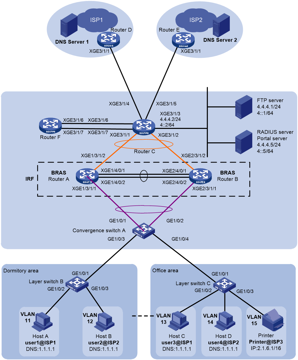
Table 10 IP planning table
|
Device |
Interface |
IP address |
Device |
Interface |
IP address |
|
RADIUS server |
- |
4.4.4.5/24 |
DNS Server 1 |
RAGG1 |
30.1.1.1/24 |
|
Portal server |
- |
4.4.4.5/24 |
DNS Server 2 |
- |
50.1.1.1/24 |
|
Router C |
RAGG1023 |
100.1.1.2/24 |
IRF(BRAS) |
RAGG1.1 |
- |
|
|
XGE3/1/1 |
- |
|
RAGG1023 |
100.1.1.1/24 |
|
|
XGE3/1/2 |
- |
|
XGE1/3/1/1 |
- |
|
|
XGE3/1/3 |
4.4.4.2/24 |
|
XGE2/3/1/1 |
- |
|
|
XGE3/1/4 |
3.3.3.1/24 |
|
XGE1/3/1/2 |
- |
|
|
XGE3/1/5 |
5.5.5.1/24 |
|
XGE2/3/1/2 |
- |
|
|
XGE3/1/7 |
- |
|
LoopBack1 |
80.1.1.1/32 |
|
|
XGE3/1/7.100 |
6.6.100.1/24 |
|
XGE3/1/7 |
- |
|
|
XGE3/1/7.200 |
6.6.200.1/24 |
|
XGE3/1/7.100 |
6.6.100.2/24 |
|
|
XGE3/1/6 |
7.7.7.1/24 |
|
XGE3/1/7.200 |
6.6.200.2/24 |
|
Router D |
XGE3/1/1 |
3.3.3.2/24 |
|
XGE3/1/6 |
7.7.7.2/24 |
|
|
|
|
Router E |
XGE3/1/1 |
5.5.5.2/24 |
Analysis
· To avoid the impact of a single point of failure in member devices on normal traffic forwarding, configure multichassis aggregate interfaces on the IRF fabric for traffic forwarding.
· To minimize the impact of IRF fabric split on services, configure Link Aggregation Control Protocol (LACP) Multiple Active Detection (MAD) on the IRF fabric. You need to configure LACP MAD for only one aggregate group. The intermediate device used for LACP MAD must be an H3C device and its software version used must support recognizing and processing link aggregation control protocol data units (LACPDUs) carrying active IDs. In this example, Switch A is used as the intermediate device for LACP MAD.
· Configure the access devices on the RADIUS server, and add the usernames and passwords.
· To use Srun software as a portal server, set the portal protocol and key on the access device page.
· To enable IPoE authentication for campus network access, configure a portal server on the BRAS.
· To perform authentication, authorization, and accounting for IPoE users by using RADIUS, configure a RADIUS scheme on the BRAS. Specify the authentication, authorization, and accounting servers, and apply the scheme to the authentication domain of the IPoE users.
· To securely transmit user passwords between the BRAS and RADIUS server, and verify the integrity of RADIUS server response packets on the BRAS, set shared keys on both devices for exchanging messages. In this example, the shared key is 123456.
· To achieve multiple egresses based on user groups, configure different user groups group1 and group2 on the BRAS, corresponding to users in ISP1 and ISP2 respectively. Configure a routing policy to specify the traffic forwarding egress for each user group.
· To enable a user to use the DNS server of the user’s ISP for obtaining the optimal IP address, redirect the DNS query packets and perform NAT translation based on the user’s ISP. Then, the DNS query packets from a user can be forwarded to the DNS server of the user's ISP for obtaining an IP address. This example uses Router F (SR6608) as the NTA device.
· To achieve multiple egresses based on user groups by using remote AAA server authorization, add RADIUS attributes group1 and group2 on the server, and configure RADIUS attributes, control policies, and product policies.
Restrictions and guidelines
To avoid service unavailability caused by port number conflicts, make sure the internal listening port number is not used by any well-known protocol and is not used by a TCP-based service. To view the TCP port numbers used by other services, execute the display tcp command.
Procedure
Configure the RADIUS server and portal server
|
|
NOTE: This section uses the Srun software of version 4.0.9 as an example to describe how to configure basic settings of the RADIUS server and portal server. |
1. Enter http://4.4.4.5:8081 in the address bar of a browser to log in to the server. Add access devices and RADIUS attributes:
# Select Device Management from the navigation tree. Click the Add Device tab. On the tab, click Add.
¡ Set the device name to BRAS.
¡ Set the NAS IP address to the IP address of interface LoopBack1 on the BRAS, 80.1.1.1.
¡ Set the device IP to 4.4.4.5.
¡ Select Huawei, H3C, and Srun Gateways from the NAS type list.
¡ Set the DM port to 3799.
¡ Set the RADIUS key to 123456.
¡ Select No from the whether to drop traffic list.
¡ Select h3c v1.2 from the portal server list.
¡ Set the portal key to 123456.
# Set the RADIUS trust. Select RADIUS from the navigation tree. Click the RADIUS Trust Settings link to enter the RADIUS trust settings page. Click Generate in the upper right corner until the trust is successfully generated. Then, restart the radius process of Srun.
# Click the RADIUS Service Settings tab, and specify the device to carry the ISP domain name in the username sent to the RADIUS server.
# Add RADIUS attributes group1 and group2. Taking group1 as an example.
Select RADIUS from the navigation tree, click the Add RADIUS Attribute tab, and click Add.
¡ Set the name to gp1. (Set the name to gp2 for RADIUS attribute group2.)
¡ Set the attribute name to group1. (Set the attribute name to group2 for RADIUS attribute group2.)
¡ Set the Vendor ID to 25506.
¡ Set the Vendor name to H3C.
¡ Set the attribute ID to 140.
¡ Select the value type as string.
¡ Set the dictionary file to dictionary.h3c.
¡ Select Huawei, H3C, and Srun Gateways from the NAS type list.
¡ Select the sending condition to normal user sending.
¡ Set the format to %s.
¡ Select Variability as None (use fixed values).
¡ Set the fixed value to group1. (Set the fixed value to group2 for RADIUS attribute group2).
2. Enter https://4.4.4.5:8080 in the address bar of a browser to log in to the server and configure the policy and users.
# Configure control policies group1 and group2.
Navigate to the Policy Management > Control Policy page. Click Add to add a control policy.
¡ Set the control policy to group1. (For control policy group2, set it to group2).
¡ Select group1 as the custom attribute under RADIUS. (For control policy group2, set it to group2).
# Configure product policies policy1 and policy2.
Navigate to the Policy Management > Product Policies page. Click Add to add product policies policy1 and policy2. Taking policy1 as an example.
¡ Set the product name to policy1. (For product policy policy2, set it to policy2).
¡ Choose Free Policy as the accounting mode.
¡ Select group1 as the control policy. (For product policy policy2, set it to group2).
# Add organizational structures.
Navigate to the System Settings
> Permission Management > Organizational
Structure page. Click the ![]() icon to create new dormitory
area and office area groups.
icon to create new dormitory
area and office area groups.
3. Add users:
Navigate to the User Management > Add Users page. Click Add.
¡ Add user user1 with account user1@isp1 and password pass1. Select the organizational structure as dormitory area. Select the product as policy1.
¡ Add user user2 with account user2@isp2 and password pass2. Select the organizational structure as dormitory area. Select the product as policy2.
¡ Add user user3 with account user3@isp1 and password pass3. Select the organizational structure as office area. Select the product as policy1.
¡ Add user user4 with account user4@isp2 and password pass4. Select the organizational structure as office area. Select the product as policy2.
Configure IP addresses and routes
1. Configure Router C:
# Assign IP address 4.4.4.2/24 to Ten-GigabitEthernet 3/1/3 on Router C.
<RouterC> system-view
[RouterC] interface ten-gigabitethernet 3/1/3
[RouterC-Ten-GigabitEthernet3/1/3] ip address 4.4.4.2 24
[RouterC-Ten-GigabitEthernet3/1/3] quit
# Assign IP address 3.3.3.1/24 to Ten-GigabitEthernet 3/1/4 on Router C.
[RouterC] interface ten-gigabitethernet 3/1/4
[RouterC-Ten-GigabitEthernet3/1/4] ip address 3.3.3.1 24
[RouterC-Ten-GigabitEthernet3/1/4] quit
# Assign IP address 5.5.5.1/24 to Ten-GigabitEthernet 3/1/5 on Router C.
[RouterC] interface ten-gigabitethernet 3/1/5
[RouterC-Ten-GigabitEthernet3/1/5] ip address 5.5.5.1 24
[RouterC-Ten-GigabitEthernet3/1/5] quit
# Assign IP address 7.7.7.1/24 to Ten-GigabitEthernet 3/1/6 on Router C.
[RouterC] interface ten-gigabitethernet 3/1/6
[RouterC-Ten-GigabitEthernet3/1/6] ip address 7.7.7.1 24
[RouterC-Ten-GigabitEthernet3/1/6] quit
# Assign IP address 6.6.100.1/24 to Ten-GigabitEthernet 3/1/7.100 on Router C.
[RouterC] interface ten-gigabitethernet 3/1/7.100
[RouterC-Ten-GigabitEthernet3/1/7.100] ip address 6.6.100.1 24
[RouterC-Ten-GigabitEthernet3/1/7.100] quit
# Assign IP address 6.6.200.1/24 to Ten-GigabitEthernet 3/1/7.200 on Router C.
[RouterC] interface ten-gigabitethernet 3/1/7.200
[RouterC-Ten-GigabitEthernet3/1/7.200] ip address 6.6.200.1 24
[RouterC-Ten-GigabitEthernet3/1/7.200] quit
# Configure the static route from Router C to users.
[RouterC] ip route-static 2.1.0.0 16 100.1.1.1
# Configure the static route from Router C to ISP1.
[RouterC] ip route-static 0.0.0.0 0 3.3.3.2
# Configure the static route from Router C to ISP2.
[RouterC] ip route-static 0.0.0.0 0 5.5.5.2
2. Configure Router F:
# Assign IP address 6.6.100.2/24 to Ten-GigabitEthernet 3/1/7.100 on Router F.
<RouterF> system-view
[RouterF] interface ten-gigabitethernet 3/1/7.100
[RouterF-Ten-GigabitEthernet3/1/7.100] ip address 6.6.100.2 24
[RouterF-Ten-GigabitEthernet3/1/7.100] quit
# Assign IP address 6.6.200.2/24 to Ten-GigabitEthernet 3/1/7.200 on Router F.
<RouterF> system-view
[RouterF] interface ten-gigabitethernet 3/1/7.200
[RouterF-Ten-GigabitEthernet3/1/7.200] ip address 6.6.200.2 24
[RouterF-Ten-GigabitEthernet3/1/7.200] quit
# Configure the static route from Router F to users.
[RouterF] ip route-static 2.1.0.0 16 6.6.100.1
[RouterF] ip route-static 2.1.0.0 16 6.6.200.1
# Configure the static route from Router F to Router C. (Access to servers and operators.)
[RouterF] ip route-static 0.0.0.0 0 7.7.7.1
Set up an IRF fabric
1. Configure Router A and Router B to form an IRF fabric:
# Configure member ID 1 for Router A. Create IRF port 2, and bind it to physical interfaces Ten-GigabitEthernet 4/0/1 and Ten-GigabitEthernet 4/0/2.
<RouterA> system-view
[RouterA] irf member 1 priority 2
[RouterA] interface ten-gigabitethernet 4/0/1
[RouterA-Ten-GigabitEthernet4/0/1] port link-mode bridge
[RouterA-Ten-GigabitEthernet4/0/1] quit
[RouterA] interface ten-gigabitethernet 4/0/2
[RouterA-Ten-GigabitEthernet4/0/2] port link-mode bridge
[RouterA-Ten-GigabitEthernet4/0/2] quit
[RouterA] irf-port 2
[RouterA-irf-port2] port group interface ten-gigabitethernet 4/0/1
[RouterA-irf-port2] port group interface ten-gigabitethernet 4/0/2
[RouterA-irf-port2] quit
# Save the current configuration into the next startup configuration file.
[RouterA] quit
<RouterA> save
# Enable IRF mode.
<RouterA> system-view
[RouterA] chassis convert mode irf
The device will switch to IRF mode and reboot. Continue?[Y/N]:y
You are recommended to save the current running configuration and specify the configuration file for the next startup. Now save the running configuration to the next-startup configuration file? [Y/N]:y
Please input the file name(*.cfg)[cfa0:/test.cfg]
(To leave the existing filename unchanged, press the enter key):
cfa0:/test.cfg exists, overwrite? [Y/N]:y
Validating file. Please wait...
Saved the current configuration to mainboard device successfully.
Do you want to convert the content of the next startup configuration file cfa0:/test.cfg to make it available in IRF mode? [Y/N]:y
Now rebooting, please wait...
After reboot, Router A forms an IRF fabric with only one member device.
# Configure member ID 2 for Router B. Create IRF port 1, and bind it to physical interfaces Ten-GigabitEthernet 4/0/1 and Ten-GigabitEthernet 4/0/2.
<RouterB> system-view
[RouterB] irf member 2 priority 1
[RouterB] interface ten-gigabitethernet 4/0/1
[RouterB-Ten-GigabitEthernet4/0/1] port link-mode bridge
[RouterB-Ten-GigabitEthernet4/0/1] quit
[RouterB] interface ten-gigabitethernet 4/0/2
[RouterB-Ten-GigabitEthernet4/0/2] port link-mode bridge
[RouterB-Ten-GigabitEthernet4/0/2] quit
[RouterB] irf-port 1
[RouterB-irf-port1] port group interface ten-gigabitethernet 4/0/1
[RouterB-irf-port1] port group interface ten-gigabitethernet 4/0/2
[RouterB-irf-port1] quit
# Save the current configuration into the next startup configuration file.
[RouterB] quit
<RouterB> save
# Enable IRF mode.
<RouterB> system-view
[RouterB] chassis convert mode irf
The device will switch to IRF mode and reboot. Continue?[Y/N]:y
You are recommended to save the current running configuration and specify the configuration file for the next startup. Now save the running configuration to the next-startup configuration file? [Y/N]:y
Please input the file name(*.cfg)[cfa0:/test.cfg]
(To leave the existing filename unchanged, press the enter key):
cfa0:/test.cfg exists, overwrite? [Y/N]:y
Validating file. Please wait...
Saved the current configuration to mainboard device successfully.
Do you want to convert the content of the next startup configuration file cfa0:/test.cfg to make it available in IRF mode? [Y/N]:y
Now rebooting, please wait...
After reboot, Router B forms an IRF fabric with Router A.
2. Configure downlink services of the IRF fabric:
a. Configure LACP MAD:
|
|
NOTE: In this example, Router A acts as the master member in the IRF fabric and acts as the BRAS in the IPoE configuration. For ease of understanding, Router A is referred to as IRF in the IRF fabric configuration section and BRAS in the IPoE configuration section. |
After the IRF fabric is set up, you can configure various service modules. Once the IRF fabric is set up, you can log in to any member device for configuration. The default device name is the name of the master member device, which is Router A in this example.
# Create a dynamic aggregation group numbered 1 for connecting to Switch A and enable LACP MAD.
<IRF> system-view
[IRF] interface route-aggregation 1
[IRF-Route-Aggregation1] link-aggregation mode dynamic
[IRF-Route-Aggregation1] mad enable
You need to assign a domain ID (range: 0-4294967295)
[Current domain is: 0]:
The assigned domain ID is: 0
MAD LACP only enable on dynamic aggregation interface.
[IRF-Route-Aggregation1] quit
# Assign the interfaces connecting to Switch A to aggregation group 1.
[IRF] interface ten-gigabitethernet 1/3/1/1
[IRF-Ten-GigabitEthernet1/3/1/1] port link-aggregation group 1
[IRF-Ten-GigabitEthernet1/3/1/1] quit
[IRF] interface ten-gigabitethernet 2/3/1/1
[IRF-Ten-GigabitEthernet2/3/1/1] port link-aggregation group 1
[IRF-Ten-GigabitEthernet2/3/1/1] quit
b. Configure Switch A:
# Create a dynamic aggregation group numbered 1 for connecting to the IRF fabric. This aggregation group is also used for LACP MAD.
<SwitchA> system-view
[SwitchA] interface bridge-aggregation 1
[SwitchA-Bridge-Aggregation1] link-aggregation mode dynamic
[SwitchA-Bridge-Aggregation1] quit
# Assign the interfaces connecting to the IRF fabric to aggregation group 1.
[SwitchA] interface gigabitethernet 1/0/1
[SwitchA-GigabitEthernet1/0/1] port link-aggregation group 1
[SwitchA-GigabitEthernet1/0/1] quit
[SwitchA] interface gigabitethernet 1/0/2
[SwitchA-GigabitEthernet1/0/2] port link-aggregation group 1
[SwitchA-GigabitEthernet1/0/2] quit
3. Configure uplink services of the IRF fabric:
a. Configure an aggregation group on the IRF fabric:
# Create a dynamic aggregation group numbered 1023 for connecting to border router Router C. Assign IPv4 address 100.1.1.1/24 and IPv6 address 100::1/64 to the aggregate interface.
[IRF] interface route-aggregation 1023
[IRF-Route-Aggregation1023] link-aggregation mode dynamic
[IRF-Route-Aggregation1023] ip address 100.1.1.1 24
[IRF-Route-Aggregation1023] ipv6 address 100::1 64
[IRF-Route-Aggregation1023] quit
# Assign the interfaces connecting to Router C to aggregation group 1023.
[IRF] interface ten-gigabitethernet 1/3/1/2
[IRF-Ten-GigabitEthernet1/3/1/2] port link-aggregation group 1023
[IRF-Ten-GigabitEthernet1/3/1/2] quit
[IRF] interface ten-gigabitethernet 2/3/1/2
[IRF-Ten-GigabitEthernet2/3/1/2] port link-aggregation group 1023
[IRF-Ten-GigabitEthernet2/3/1/2] quit
# Configure a static default route to Router C for accessing the servers and Internet.
[IRF] ip route-static 0.0.0.0 24 100.1.1.2
[IRF] ipv6 route-static :: 0 100::2
b. Configure Router C:
|
|
NOTE: The section only covers the configuration for connecting to the IRF fabric and does not describe the routing protocol used for the external network. |
# Create a dynamic aggregation group numbered 1023 for connecting to the IRF fabric. Assign IPv4 address 100.1.1.2/24 and IPv6 address 100::2/64 to the aggregate interface.
<RouterC> system-view
[RouterC] interface route-aggregation 1023
[RouterC-Route-Aggregation1023] link-aggregation mode dynamic
[RouterC-Route-Aggregation1023] ip address 100.1.1.2 24
[RouterC-Route-Aggregation1023] ipv6 address 100::2 64
[RouterC-Route-Aggregation1023] quit
# Assign the interfaces connecting to the IRF fabric to aggregation group 1023.
[RouterC] interface ten-gigabitethernet 3/1/1
[RouterC-Ten-GigabitEthernet3/1/1] port link-aggregation group 1023
[RouterC-Ten-GigabitEthernet3/1/1] quit
[RouterC] interface ten-gigabitethernet 3/1/2
[RouterC-Ten-GigabitEthernet3/1/2] port link-aggregation group 1023
[RouterC-Ten-GigabitEthernet3/1/2] quit
Configure BRAS
1. Configure the DHCP server:
# Enable DHCP globally.
[BRAS] dhcp enable
# Enable the DHCP server to return a DHCP-NAK message if the client notions of their IP addresses are incorrect.
[BRAS] dhcp server request-ip-address check
# Create DHCP relay address pool pool1, and specify the DHCPv4 gateway address and the network segment address for the address pool.
[BRAS] ip pool pool1 bas local
[BRAS-ip-pool-pool1] gateway 2.1.1.1 16
# Configure the address for DNS server.
[BRAS-ip-pool-pool1] dns-list 8.8.8.8
# Exclude the gateway IP address 2.1.1.1 and the printer static IP address 2.1.6.1 from dynamic allocation.
[BRAS-ip-pool-pool1] forbidden-ip 2.1.1.1 2.1.6.1
[BRAS-ip-pool-pool1] quit
2. Create an IPv4 portal authentication server named newpt1. Specify IP address 4.4.4.5 and plaintext password 123456 for the server.
[BRAS] portal server newpt1
[BRAS-portal-server-newpt1] ip 4.4.4.5 key simple 123456
[BRAS-portal-server-newpt1] quit
3. Specify the HTTPS redirect listening port number. Make sure it does not conflict with a port in use. To view the TCP port numbers used by other services, execute the display tcp command.
[BRAS] http-redirect https-port 11111
4. Configure the device to get user access information from ARP/ND entries.
[BRAS] portal access-info trust arp
[BRAS] portal access-info trust nd
5. Create local user groups:
# Create a user group named pre for the preauthentication domain.
[BRAS] user-group pre
New user group added.
[BRAS-ugroup-pre] quit
# Create a user group named group1.
[BRAS] user-group group1
New user group added.
[BRAS-ugroup-group1] quit
# Create a user group named group2.
[BRAS] user-group group2
New user group added.
[BRAS-ugroup-group2] quit
6. Configure QoS:
a. Configure the ACLs for users in the preauthentication domain:
# Create IPv4 advanced ACL web_permit to match packets destined to the portal server for users in user group pre.
[BRAS] acl advanced name web_permit
[BRAS-acl-ipv4-adv-web_permit] rule 0 permit ip destination 4.4.4.5 0 user-group pre
[BRAS-acl-ipv4-adv-web_permit] quit
# Create IPv4 advanced ACL neiwang to match packets destined to the internal network server for users in user groups pre.
[BRAS] acl advanced name neiwang
[BRAS-acl-ipv4-adv-neiwang] rule 0 permit ip destination 4.4.4.1 0 user-group pre
[BRAS-acl-ipv4-adv-neiwang] quit
# Create IPv4 advanced ACL web_http to match TCP packets with destination port 80 (HTTP packets) for users in user group pre.
[BRAS] acl advanced name web_http
[BRAS-acl-ipv4-adv-web_http] rule 0 permit tcp destination-port eq www user-group pre
[BRAS-acl-ipv4-adv-web_http] quit
# Create IPv4 advanced ACL web_https to match TCP packets with destination port 443 (HTTPS packets) for users in group pre.
[BRAS] acl advanced name web_https
[BRAS-acl-ipv4-adv-web_https] rule 0 permit tcp destination-port eq 443 user-group pre
[BRAS-acl-ipv4-adv-web_https] quit
# Create IPv4 advanced ACL ip to match IP packets for users in user group pre.
[BRAS] acl advanced name ip
[BRAS-acl-ipv4-adv-ip] rule 0 permit ip user-group pre
[BRAS-acl-ipv4-adv-ip] quit
# Create IPv4 advanced ACL neiwang_out to match packets sourced from the internal network server for users in user groups pre and web.
[BRAS] acl advanced name neiwang_out
[BRAS-acl-ipv4-adv-neiwang_out] rule 0 permit ip source 4.4.4.1 0 user-group pre
[BRAS-acl-ipv4-adv-neiwang_out] quit
# Create IPv4 advanced ACL web_out to match packets sourced from the portal server for users in user group pre.
[BRAS] acl advanced name web_out
[BRAS-acl-ipv4-adv-web_out] rule 0 permit ip source 4.4.4.5 0 user-group pre
[BRAS-acl-ipv4-adv-web_out] quit
# Create IPv4 advanced ACL redirect_nat_group to match DNS packets destined to 8.8.8.8 for users in group group1 and group2.
[BRAS] acl advanced name redirect_nat_group1
[BRAS-acl-ipv4-adv-redirect_nat_group1] rule 5 permit udp destination 8.8.8.8 0 destination-port eq dns user-group group1
[BRAS-acl-ipv4-adv-redirect_nat_group1] quit
[BRAS] acl advanced name redirect_nat_group2
[BRAS-acl-ipv4-adv-redirect_nat_group2] rule 5 permit udp destination 8.8.8.8 0 destination-port eq dns user-group group2
[BRAS-acl-ipv4-adv-redirect_nat_group2] quit
# Create IPv4 advanced ACL redirect_isp_group to match IP packets for users in user group group1 and group2.
[BRAS] acl advanced name redirect_isp_group1
[BRAS-acl-ipv4-adv-redirect_isp_group1] rule 0 permit ip user-group group1
[BRAS-acl-ipv4-adv-redirect_isp_group1] quit
[BRAS] acl advanced name redirect_isp_group2
[BRAS-acl-ipv4-adv-redirect_isp_group2] rule 0 permit ip user-group group2
[BRAS-acl-ipv4-adv-redirect_isp_group2] quit
b. Configure traffic classes for users in the preauthentication domain:
# Create a traffic class named web_permit, and use ACL web_permit as the match criterion.
[BRAS] traffic classifier web_permit operator or
[BRAS-classifier-web_permit] if-match acl name web_permit
[BRAS-classifier-web_permit] quit
# Create a traffic class named neiwang, and use ACL neiwang as the match criterion.
[BRAS] traffic classifier neiwang operator or
[BRAS-classifier-neiwang] if-match acl name neiwang
[BRAS-classifier-neiwang] quit
# Create a traffic class named web_http and use ACL web_http as the match criterion.
[BRAS] traffic classifier web_http operator or
[BRAS-classifier-web_http] if-match acl name web_http
[BRAS-classifier-web_http] quit
# Create a traffic class named web_https, and use ACL web_https as the match criterion.
[BRAS] traffic classifier web_https operator or
[BRAS-classifier-web_https] if-match acl name web_https
[BRAS-classifier-web_https] quit
# Create a traffic class named web_deny, and use ACL ip as the match criterion.
[BRAS] traffic classifier web_deny operator or
[BRAS-classifier-web_deny] if-match acl name ip
[BRAS-classifier-web_deny] quit
# Create a traffic class named neiwang_out, and use ACL neiwang_out as the match criterion.
[BRAS] traffic classifier neiwang_out operator or
[BRAS-classifier-neiwang_out] if-match acl name neiwang_out
[BRAS-classifier-neiwang_out] quit
# Create a traffic class named web_out, and use ACL web_out as the match criterion.
[BRAS] traffic classifier web_out operator or
[BRAS-classifier-web_out] if-match acl name web_out
[BRAS-classifier-web_out] quit
# Create a traffic class named redirect_nat_group1, and use ACL redirect_nat_group1 as the match criterion.
[BRAS] traffic classifier redirect_nat_group1 operator or
[BRAS-classifier-redirect_nat_group1] if-match acl name redirect_nat_group1
[BRAS-classifier-redirect_nat_group1] quit
# Create a traffic class named redirect_nat_group2, and use ACL redirect_nat_group2 as the match criterion.
[BRAS] traffic classifier redirect_nat_group2 operator or
[BRAS-classifier-redirect_nat_group2] if-match acl name redirect_nat_group2
[BRAS-classifier-redirect_nat_group2] quit
# Create a traffic class named redirect_isp_group1, and use ACL redirect_isp_group1 as the match criterion.
[BRAS] traffic classifier redirect_isp_group1 operator or
[BRAS-classifier-redirect_isp_group1] if-match acl name redirect_isp_group1
[BRAS-classifier-redirect_isp_group1] quit
# Create a traffic class named redirect_isp_group2, and use ACL redirect_isp_group2 as the match criterion.
[BRAS] traffic classifier redirect_isp_group2 operator or
[BRAS-classifier-redirect_isp_group2] if-match acl name redirect_isp_group2
[BRAS-classifier-redirect_isp_group2] quit
c. Configure traffic behaviors:
# Configure a traffic behavior named web_permit to permit packets.
[BRAS] traffic behavior web_permit
[BRAS-behavior-neiwang] filter permit
[BRAS-behavior-neiwang] free account
[BRAS-behavior-web_permit] quit
# Configure a traffic behavior named neiwang to permit packets.
[BRAS] traffic behavior neiwang
[BRAS-behavior-neiwang] remark account-level 2
[BRAS-behavior-neiwang] quit
# Configure a traffic behavior named web_http to redirect packets to the CPU.
[BRAS] traffic behavior web_http
[BRAS-behavior-web_http] redirect http-to-cpu
[BRAS-behavior-web_http] quit
# Configure a traffic behavior named web_https to redirect packets to the CPU.
[BRAS] traffic behavior web_https
[BRAS-behavior-web_https] redirect https-to-cpu
[BRAS-behavior-web_https] quit
# Create a traffic behavior named web_deny to deny packets.
[BRAS] traffic behavior web_deny
[BRAS-behavior-web_deny] filter deny
[BRAS-behavior-web_deny] free account
[BRAS-behavior-web_deny] quit
# Configure a traffic behavior named neiwang_out to permit packets.
[BRAS] traffic behavior neiwang_out
[BRAS-behavior-neiwang_out] filter permit
[BRAS-behavior-neiwang_out] free account
[BRAS-behavior-neiwang_out] quit
# Configure a traffic behavior named web_out to permit packets.
[BRAS] traffic behavior web_out
[BRAS-behavior-web_out] filter permit
[BRAS-behavior-web_out] free account
[BRAS-behavior-web_out] quit
# Configure a traffic behavior named redirect_nat_group1 to redirect the DNS packets destined to 8.8.8.8 sent by users in user group group1 to subinterface GigabitEthernet 3/1/7.100 on Router F.
[BRAS] traffic behavior redirect_nat_group1
[BRAS-behavior-redirect_nat_group1] redirect next-hop 6.6.100.2
[BRAS-behavior-redirect_nat_group1] quit
# Configure a traffic behavior named redirect_nat_group2 to redirect the DNS packets destined to 8.8.8.8 sent by users in user group group2 to subinterface GigabitEthernet 3/1/7.200 of Router F.
[BRAS] traffic behavior redirect_nat_group2
[BRAS-behavior-redirect_nat_group2] redirect next-hop 6.6.200.2
[BRAS-behavior-redirect_nat_group2] quit
# Configure a traffic behavior named redirect_isp_group1 to forward all user packets in user group group1 except the DNS packets destined to 8.8.8.8 within ISP1.
[BRAS] traffic behavior redirect_isp_group1
[BRAS-behavior-redirect_isp_group1] redirect next-hop 3.3.3.2
[BRAS-behavior-redirect_isp_group1] quit
# Configure a traffic behavior named redirect_isp_group2 to forward all user packets in user group group2 except the DNS packets destined to 8.8.8.8 within ISP2.
[BRAS] traffic behavior redirect_isp_group2
[BRAS-behavior-redirect_isp_group2] redirect next-hop 5.5.5.2
[BRAS-behavior-redirect_isp_group2] quit
d. Configure QoS policies:
# Configure an inbound QoS policy named web.
[BRAS] qos policy web
# Associate traffic classes with traffic behaviors. For users in user group pre:
- Permit packets destined to the portal server and internal network server.
- Redirect packets with destination ports 80 (HTTP) and 443 (HTTPS) to the CPU.
- Redirect other packets to the CPU. If the redirected packets fail to pass transparent authentication, discard the packets.
[BRAS-qospolicy-web] classifier web_permit behavior web_permit
[BRAS-qospolicy-web] classifier neiwang behavior neiwang
[BRAS-qospolicy-web] classifier web_http behavior web_http
[BRAS-qospolicy-web] classifier web_https behavior web_https
[BRAS-qospolicy-web] classifier web_deny behavior web_deny
[BRAS-qospolicy-web] quit
# Associate traffic classes with traffic behaviors. For users in user group group1 or group2:
- Redirect the DNS packets destined to 8.8.8.8 sent by users in the user group group1 to Router F for NAT translation.
- Redirect the DNS packets destined to 8.8.8.8 sent by users in the user group group2 to Router F for NAT translation.
- Forward all user packets in the user group group1 except the DNS packets destined to 8.8.8.8 in ISP1.
- Forward all user packets in the user group group2 except the DNS packets destined to 8.8.8.8 in ISP2.
[BRAS-qospolicy-web] classifier redirect_nat_group1 behavior redirect_nat_group1
[BRAS-qospolicy-web] classifier redirect_nat_group2 behavior redirect_nat_group2
[BRAS-qospolicy-web] classifier redirect_isp_group1 behavior redirect_isp_group1
[BRAS-qospolicy-web] classifier redirect_isp_group2 behavior redirect_isp_group2
[BRAS-qospolicy-web] quit
# Configure an outbound QoS policy named out.
[BRAS] qos policy out
# Associate traffic classes with traffic behaviors to permit packet sourced from the portal server and internal network server for users in user group pre and deny any other packets.
[BRAS-qospolicy-out] classifier web_out behavior web_out
[BRAS-qospolicy-out] classifier neiwang_out behavior neiwang_out
[BRAS-qospolicy-out] classifier web_deny behavior web_deny
[BRAS-qospolicy-out] quit
e. Apply QoS policies:
# Apply QoS policy web to the incoming traffic. To identify whether the QoS policy takes effect, execute the display qos policy global inbound command.
[BRAS] qos apply policy web global inbound
# Apply QoS policy out to the outgoing traffic. To identify whether the QoS policy takes effect, execute the display qos policy global outbound command.
[BRAS] qos apply policy out global outbound
7. Configure a RADIUS scheme:
# Create RADIUS scheme rs1, and enter its view.
[BRAS] radius scheme rs1
# Configure the primary authentication and accounting servers and the keys for secure RADIUS authentication and accounting communication for the RADIUS scheme.
[BRAS-radius-rs1] primary authentication 4.4.4.5
[BRAS-radius-rs1] primary accounting 4.4.4.5
[BRAS-radius-rs1] key authentication simple 123456
[BRAS-radius-rs1] key accounting simple 123456
# Exclude the ISP name from the username sent to the RADIUS server.
[BRAS-radius-rs1] user-name-format without-domain
# Specify source IP address 80.1.1.1 for outgoing RADIUS packets.
[BRAS-radius-rs1] nas-ip 80.1.1.1
[BRAS-radius-rs1] quit
# Specify the DAC as 4.4.4.5. Set the shared key to 123456 in plaintext form for secure communication between the DAS and DAC.
[BRAS] radius dynamic-author server
[BRAS-radius-da-server] client ip 4.4.4.5 key simple 123456
[BRAS-radius-da-server] quit
8. Configure the preauthentication domain and Web authentication domain:
# Configure the preauthentication domain for IPoE users.
[BRAS] domain name dm1
[BRAS-isp-dm1] authentication ipoe none
[BRAS-isp-dm1] authorization ipoe none
[BRAS-isp-dm1] accounting ipoe none
# Configure the authorization user group and address pool in the preauthentication domain.
[BRAS-isp-dm1] authorization-attribute user-group pre
[BRAS-isp-dm1] authorization-attribute ip-pool pool1
# Configure the Web authentication page URL.
[BRAS-isp-dm1] web-server url http://www.ipv4.web.com
# Configure the Web authentication domain for IPoE users.
[BRAS] domain name dm2
[BRAS-isp-dm2] authentication ipoe radius-scheme rs1
[BRAS-isp-dm2] authorization ipoe radius-scheme rs1
[BRAS-isp-dm2] accounting ipoe radius-scheme rs1
[BRAS-isp-dm2] authorization-attribute car inbound cir 5120 outbound cir 5120
9. Configure IPoE:
# Enable IPoE and configure the Layer 2 access mode.
[BRAS] interface route-aggregation 1.1
[BRAS–Route-Aggregation1.1] ip subscriber l2-connected enable
# Enable unclassified-IP packet initiation.
[BRAS–Route-Aggregation1.1] ip subscriber initiator unclassified-ip enable matching-user
# Configure the Web MAC authentication method for IPoE users.
[BRAS–Route-Aggregation1.1] ip subscriber authentication-method web mac-auth
The operation may cut all users on this interface. Continue?[Y/N]:y
# Configure the Web preauthentication domain as dm1, and Web and Web MAC authentication domain as dm2.
[BRAS–Route-Aggregation1.1] ip subscriber pre-auth domain dm1
[BRAS–Route-Aggregation1.1] ip subscriber web-auth domain dm2
[BRAS–Route-Aggregation1.1] ip subscriber mac-auth domain dm2
10. Configure VLAN termination:
# Configure the user VLAN Dot1q termination function on the subinterface.
[BRAS-Route-Aggregation1.1] user-vlan dot1q vid 11 to 15
# Configure the interface to send broadcast and multicast packets.
[BRAS-Route-Aggregation1.1] vlan-termination broadcast enable
# Enable the local proxy ARP function on the interface..
[BRAS-Route-Aggregation1.1] local-proxy-arp enable
[BRAS–Route-Aggregation1.1] quit
11. Configure attack defense:
¡ Configure source MAC-based ARP attack detection:
# Enable the source MAC-based ARP attack detection feature and specify the filter handling method.
[BRAS] arp source-mac filter
# Set the check interval for source MAC-based ARP attack detection to 5 seconds.
[BRAS] arp source-mac check-interval 5
# Set the threshold for source MAC-based ARP attack detection to 30.
[BRAS] arp source-mac threshold 30
# Set the aging time for ARP attack entries to 300 seconds.
[BRAS] arp source-mac aging-time 300
¡ Configure source MAC-based ND attack detection:
# Enable the source MAC-based ND attack detection feature and specify the filter handling method.
[BRAS] ipv6 nd source-mac filter
# Set the check interval for source MAC-based ND attack detection to 5 seconds.
[BRAS] ipv6 nd source-mac check-interval 5
# Set the threshold for source MAC-based ND attack detection to 30.
[BRAS] ipv6 nd source-mac threshold 30
# Set the aging time for ND attack entries to 300 seconds.
[BRAS] ipv6 nd source-mac aging-time 300
¡ Configure DHCP flood attack protection:
# Enable DHCP flood attack protection on interface Route-Aggregation1.1.
[BRAS] interface route-aggregation 1.1
[BRAS-Route-Aggregation1.1] dhcp flood-protection enable
[BRAS–Route-Aggregation1.1] quit
# Configure the device to allow a maximum of 30 DHCP packets per 10000 milliseconds from each DHCP client.
[BRAS] dhcp flood-protection threshold 30 10000
# Set the DHCP flood attack entry aging time to 300 seconds.
[BRAS] dhcp flood-protection aging-time 300
¡ Configure DHCPv6 flood attack protection:
# Enable DHCPv6 flood attack protection on interface Route-Aggregation1.1.
[BRAS] interface route-aggregation 1.1
[BRAS-Route-Aggregation1.1] ipv6 dhcp flood-protection enable
[BRAS-Route-Aggregation1.1] quit
# Configure the device to allow a maximum of 30 DHCPv6 packets per 10000 milliseconds from each DHCPv6 client.
[BRAS] ipv6 dhcp flood-protection threshold 30 10000
# Set the DHCPv6 flood attack entry aging time to 300 seconds.
[BRAS] ipv6 dhcp flood-protection aging-time 300
¡ Enable ICMP/ICMPv6 fast reply:
[BRAS] ip icmp fast-reply enable
[BRAS] ipv6 icmpv6 fast-reply enable
¡ Configure TCP SYN flood attack prevention:
# Enable flow-based TCP SYN flood attack prevention.
[BRAS] tcp anti-syn-flood flow-based enable
# Set the check interval to 20 seconds for flow-based TCP SYN flood attack prevention.
[BRAS] tcp anti-syn-flood flow-based check-interval 20
# Set the threshold to 2000 for triggering flow-based TCP SYN flood attack prevention.
[BRAS] tcp anti-syn-flood flow-based threshold 2000
# Set the flow-based TCP SYN flood attack prevention duration to 5 minutes.
[BRAS] tcp anti-syn-flood flow-based duration 5
¡ Configure HTTP/HTTPS attack defense:
# Enable destination IP-based IPoE HTTP/HTTPS attack defense.
[BRAS] ip subscriber http-defense destination-ip enable
# Trigger attack defense when the total number of HTTP/HTTPS packets sent to the same destination IP address within 300 seconds reaches 6000.
[BRAS] ip subscriber http-defense destination-ip threshold 6000 interval 300
¡ Configure HTTP packet fast reply:
# Enable HTTP packet fast reply on interface Route-Aggregation 1.1.
[BRAS] interface route-aggregation 1.1
[BRAS-Route-Aggregation1.1] ip subscriber http-fast-reply enable
[BRAS-Route-Aggregation1.1] quit
Configure Router F (NAT device)
|
|
IMPORTANT: · Take the SR6608 router as the NAT device for example. When using the SR8800-X/SR8800-F/CR16000-F router as a NAT device, in addition to the current configuration, you must also use the nat service command to specify the slot that provides NAT processing on the interface that has NAT services configured. If you do not do that, the NAT function on the interface will not take effect. For more information about the nat service command, see the command references for your device. · For DNS request and response packets to be forwarded correctly, make sure the outgoing interfaces of the route from Router F to the user network segment 2.1.0.0/16 are Ten-Gigabitethernet 3/1/7.100 and Ten-Gigabitethernet 3/1/7.200, and the outgoing interface of the route to the DNS server is Ten-Gigabitethernet 3/1/6. |
1. Configure internal NAT servers:
# Configure the internal NAT server on interface Ten-GigabitEthernet 3/1/7.100. Perform destination IP address translation (8.8.8.8->30.1.1.1) on DNS packets received from this interface. Perform source IP address translation (30.1.1.1->8.8.8.8) on DNS packets sent out this interface.
[RouterF] interface ten-gigabitethernet 3/1/7.100
[RouterF-Ten-GigabitEthernet3/1/7.100] nat server protocol udp global 8.8.8.8 53 inside 30.1.1.1 53
# Configure interface Ten-GigabitEthernet 3/1/7.100 to terminate VLAN packets with the outermost VLAN ID of 100.
[RouterF-Ten-GigabitEthernet3/1/7.100] vlan-type dot1q vid 100
[RouterF-Ten-GigabitEthernet3/1/7.100] quit
# Configure the internal NAT server on interface Ten-GigabitEthernet 3/1/7.200. Perform destination IP address translation (8.8.8.8->50.1.1.1) on DNS packets received from this interface. Perform source IP address translation (50.1.1.1->8.8.8.8) on DNS packets sent out from this interface.
[RouterF] interface ten-gigabitethernet 3/1/7.200
[RouterF-Ten-GigabitEthernet3/1/7.200] nat server protocol udp global 8.8.8.8 53 inside 50.1.1.1 53
# Configure interface Ten-GigabitEthernet 3/1/7.200 to terminate VLAN packets with the outermost VLAN ID of 200.
[RouterF-Ten-GigabitEthernet3/1/7.200] vlan-type dot1q vid 200
[RouterF-Ten-GigabitEthernet3/1/7.200] quit
2. Configure outbound dynamic NAT:
# Configure ACL 3000 to match the DNS packets of users whose source IP addresses are on the 2.1.0.0/16 network segment and the DNS packets of the DNS server whose source IP addresses are 30.1.1.1 and 50.1.1.1.
[RouterF] acl advanced 3000
[RouterF-acl-ipv4-adv-3000] rule 5 permit udp source 2.1.0.0 0.0.255.255 source-port eq dns
[RouterF-acl-ipv4-adv-3000] rule 10 permit udp source 30.1.1.1 0 source-port eq dns
[RouterF-acl-ipv4-adv-3000] rule 15 permit udp source 50.1.1.1 0 source-port eq dns
[RouterF-acl-ipv4-adv-3000] quit
# Create address group 1 and add address group members 7.7.7.100 to 7.7.7.254.
[RouterF] nat address-group 1
[RouterF-address-group-1] address 7.7.7.100 7.7.7.254
[RouterF-address-group-1] quit
# Configure outbound dynamic address translation on interface Ten-GigabitEthernet 3/1/6. Allow packets matching ACL 3000 to use addresses in address group 1 for address translation, and use UDP port information during translation.
[RouterF] interface ten-gigabitethernet 3/1/6
[RouterF-Ten-GigabitEthernet3/1/6] nat outbound 3000 address-group 1
[RouterF-Ten-GigabitEthernet3/1/6] quit
Verifying the configuration
# Before a user passes preauthentication, users can only access the Web authentication homepage of the portal Web server.
# Users can access Internet resources after passing the preauthentication. Take Host A as an example. After the user name user1@isp1 and password pass1 are entered, the login succeeds.
# View detailed information about user user1@isp1.
[BRAS] display access-user interface route-aggregation 1.1
UserID Interface IP address MAC address S-/C-VLAN
Username Access type
IPv6 address
0x5c RAGG1.1 2.1.2.1 000c-29a6-b656 11/-
user1@isp1 L2 IPoE dynamic
-
# Enable NAT packet debugging on Router F.
<RouterF> terminal monitor
<RouterF> terminal debugging
<RouterF> debugging nat packet
# Ping www.test1.com on host A.
C:\Users>ping www.test1.com
Pinging 100.100.1.1 with 32 bytes of data:
Reply from 100.100.1.1: bytes=32 time=1ms TTL=127
Reply from 100.100.1.1: bytes=32 time=1ms TTL=127
Reply from 100.100.1.1: bytes=32 time=1ms TTL=127
Reply from 100.100.1.1: bytes=32 time=1ms TTL=127
Ping statistics for 100.100.1.1:
Packets: Sent = 4, Received = 4, Lost = 0 (0% loss),
Approximate round trip times in mili-senconds:
Minimum = 1ms, Maximum = 1ms, Average = 1ms
C:\Users>
# Print the following NAT debugging information on Router F.
<RouterF>*Apr 10 19:35:23:097 2021 RouterF NAT/7/COMMON: -MDC=1-Slot=3;
PACKET: (Ten-GigabitEthernet3/1/7.100-in-config) Protocol: UDP
2.1.2.1:64192 - 8.8.8.8: 53(VPN: 0) ------>
2.1.2.1:64192 - 30.1.1.1: 53(VPN: 0)
*Apr 10 19:35:23:097 2021 RouterF NAT/7/COMMON: -MDC=1-Slot=3;
PACKET: (Ten-GigabitEthernet3/1/6-out-config) Protocol: UDP
2.1.2.1:64192 - 30.1.1.1: 53(VPN: 0) ------>
7.7.7.116: 1754 - 30.1.1.1: 53(VPN: 0)
*Apr 10 19:35:23:098 2021 RouterF NAT/7/COMMON: -MDC=1-Slot=3;
PACKET: (Ten-GigabitEthernet3/1/6-in-session) Protocol: UDP
30.1.1.1: 53 - 7.7.7.116: 1754(VPN: 0) ------>
30.1.1.1: 53 - 2.1.2.1:64192(VPN: 0)
*Apr 10 19:35:23:098 2021 RouterF NAT/7/COMMON: -MDC=1-Slot=3;
PACKET: (Ten-GigabitEthernet3/1/7.100-out-session) Protocol: UDP
30.1.1.1: 53 - 2.1.2.1:64192(VPN: 0) ------>
8.8.8.8: 53 - 2.1.2.1:64192(VPN: 0)
The output shows that when Host A logs in as user1@isp1 and accesses the domain www.test1.com, the DNS packet destined to 8.8.8.8 sent by the user is redirected to Router F. A series of NAT translations is performed for the packet by Router F,. At last, the DNS request is sent to ISP1's DNS Server1. DNS Server1 resolves the optimal IP address 100.100.1.1 for Host A.
Configuration files
· Router C:
#
interface Route-Aggregation1023
ip address 100.1.1.2 255.255.255.0
link-aggregation mode dynamic
#
interface Ten-GigabitEthernet3/1/1
port link-aggregation group 1023
#
interface Ten-GigabitEthernet3/1/2
port link-aggregation group 1023
#
interface Ten-GigabitEthernet3/1/3
ip address 4.4.4.2 255.255.255.0
#
ip route-static 0.0.0.0 0 3.3.3.2
ip route-static 0.0.0.0 0 5.5.5.2
ip route-static 2.1.0.0 16 100.1.1.1#
· IRF (BRAS):
#
irf mac-address persistent always
irf auto-update enable
irf auto-merge enable
undo irf link-delay
irf member 1 priority 2
irf member 2 priority 1
#
irf-port 1/2
port group interface Ten-GigabitEthernet1/4/0/1 mode enhanced
port group interface Ten-GigabitEthernet1/4/0/2 mode enhanced
#
irf-port 2/1
port group interface Ten-GigabitEthernet2/4/0/1 mode enhanced
port group interface Ten-GigabitEthernet2/4/0/2 mode enhanced
#
dhcp enable
dhcp server request-ip-address check
#
traffic classifier web_http operator or
if-match acl name web_http
#
traffic classifier web_https operator or
if-match acl name web_https
#
traffic classifier web_out operator or
if-match acl name web_out
#
traffic classifier web_permit operator or
if-match acl name web_permit
#
traffic classifier web_deny operator or
if-match acl name ip
#
traffic classifier neiwang operator or
if-match acl name neiwang
#
traffic classifier neiwang_out operator or
if-match acl name neiwang_out
#
traffic classifier redirect_isp_group1 operator or
if-match acl name redirect_isp_group1
#
traffic classifier redirect_isp_group2 operator or
if-match acl name redirect_isp_group2
#
traffic classifier redirect_nat_group1 operator or
if-match acl name redirect_nat_group1
#
traffic classifier redirect_nat_group2 operator or
if-match acl name redirect_nat_group2
#
traffic behavior web_deny
filter deny
free account
#
traffic behavior web_http
redirect http-to-cpu
#
traffic behavior web_https
redirect https-to-cpu
#
traffic behavior web_out
filter permit
free account
#
traffic behavior web_permit
filter permit
free account
#
traffic behavior neiwang
filter permit
free account
#
traffic behavior neiwang_out
filter permit
free account
#
traffic behavior redirect_isp_group1
redirect next-hop 3.3.3.2
#
traffic behavior redirect_isp_group2
redirect next-hop 5.5.5.2
#
traffic behavior redirect_nat_group1
redirect next-hop 6.6.100.2
#
traffic behavior redirect_nat_group2
redirect next-hop 2.2.2.1
#
qos policy web
classifier web_permit behavior web_permit
classifier neiwang behavior neiwang
classifier web_http behavior web_http
classifier web_https behavior web_https
classifier web_deny behavior web_deny
classifier redirect_nat_group1 behavior redirect_nat_group1
classifier redirect_nat_group2 behavior redirect_nat_group2
classifier redirect_isp_group1 behavior redirect_isp_group1
classifier redirect_isp_group2 behavior redirect_isp_group2
#
qos policy out
classifier web_out behavior web_out
classifier neiwang_out behavior neiwang_out
classifier web_deny behavior web_deny
#
ip pool pool1 bas local
gateway 2.1.1.1 mask 255.255.0.0
dns-list 8.8.8.8
forbidden-ip 2.1.1.1 2.1.6.1
#
interface Route-Aggregation1
link-aggregation mode dynamic
mad enable
#
interface Route-Aggregation1.1
local-proxy-arp enable
user-vlan dot1q vid 11 to 15
vlan-termination broadcast enable
dhcp flood-protection enable
ipv6 dhcp flood-protection enable
ip subscriber l2-connected enable
ip subscriber http-fast-reply enable
ip subscriber initiator unclassified-ip enable matching-user
ip subscriber authentication-method web mac-auth
ip subscriber pre-auth domain dm1
ip subscriber web-auth domain dm2
ip subscriber mac-auth domain dm2
#
interface Route-Aggregation1023
ip address 100.1.1.1 255.255.255.0
link-aggregation mode dynamic
#
interface Ten-GigabitEthernet1/3/1/1
port link-aggregation group 1
#
interface Ten-GigabitEthernet2/3/1/1
port link-aggregation group 1
#
interface Ten-GigabitEthernet1/3/1/2
port link-aggregation group 1023
#
interface Ten-GigabitEthernet2/3/1/2
port link-aggregation group 1023
#
ip route-static 0.0.0.0 0 100.1.1.2
ipv6 route-static :: 0 100::2
#
qos apply policy web global inbound
qos apply policy out global outbound
#
acl advanced name web_http
rule 0 permit tcp destination-port eq www user-group pre
#
acl advanced name web_https
rule 0 permit tcp destination-port eq 443 user-group pre
#
acl advanced name web_out
rule 0 permit ip source 4.4.4.5 0 user-group pre
#
acl advanced name web_permit
rule 0 permit ip destination 4.4.4.5 0 user-group pre
#
acl advanced name ip
rule 0 permit ip user-group pre
#
acl advanced name neiwang
rule 0 permit ip destination 4.4.4.1 0 user-group pre
#
acl advanced name neiwang_out
rule 0 permit ip source 4.4.4.1 0 user-group pre
#
acl advanced name redirect_isp_group1
rule 0 permit ip user-group group1
#
acl advanced name redirect_isp_group2
rule 0 permit ip user-group group2
#
acl advanced name redirect_nat_group1
rule 5 permit udp destination 8.8.8.8 0 destination-port eq dns user-group group1
#
acl advanced name redirect_nat_group2
rule 5 permit udp destination 8.8.8.8 0 destination-port eq dns user-group group2
#
radius scheme rs1
primary authentication 4.4.4.5
primary accounting 4.4.4.5
key authentication simple 123456
key accounting simple 123456
user-name-format without-domain
nas-ip 80.1.1.1
#
radius dynamic-author server
client ip 4.4.4.5 key simple 123456
#
domain name dm1
authorization-attribute user-group pre
authorization-attribute ip-pool pool1
authentication ipoe none
authorization ipoe none
accounting ipoe none
web-server url http://www.ipv4.web.com
#
domain name dm2
authorization-attribute car inbound cir 5120 outbound cir 5120
authentication ipoe radius-scheme rs1
authorization ipoe radius-scheme rs1
accounting ipoe radius-scheme rs1
#
user-group group1
#
user-group group2
#
user-group pre
#
portal server newpt1
ip 4.4.4.5 simple 123456
#
portal access-info trust arp
portal access-info trust nd
#
http-redirect https-port 11111
#
tcp anti-syn-flood flow-based enable
tcp anti-syn-flood flow-based threshold 2000
tcp anti-syn-flood flow-based check-interval 20
#
ip icmp fast-reply enable
#
dhcp flood-protection threshold 30 10000
#
ipv6 dhcp flood-protection threshold 30 10000
#
ipv6 icmpv6 fast-reply enable
#
ip subscriber http-defense destination-ip enable
#
ipv6 nd source-mac filter
#
arp source-mac filter
#
· Router F (NAT):
#
nat address-group 1
address 7.7.7.100 7.7.7.254
#
interface Ten-GigabitEthernet3/1/7
#
interface Ten-GigabitEthernet3/1/7.100
ip address 6.6.100.2 255.255.255.0
nat server protocol udp global 8.8.8.8 53 inside 30.1.1.1 53
vlan-type dot1q vid 100
#
interface Ten-GigabitEthernet3/1/7.200
ip address 6.6.200.2 255.255.255.0
nat server protocol udp global 8.8.8.8 53 inside 50.1.1.1 53
vlan-type dot1q vid 200
#
interface Ten-GigabitEthernet3/1/6
ip address 7.7.7.2 255.255.255.0
nat outbound 3000 address-group 1
#
ip route-static 0.0.0.0 0 7.7.7.1
ip route-static 2.1.0.0 16 6.6.100.1
ip route-static 2.1.0.0 16 6.6.200.1
#
acl advanced 3000
rule 5 permit udp source 2.1.0.0 0.0.255.255 source-port eq dns
rule 10 permit udp source 30.1.1.1 0 source-port eq dns
rule 15 permit udp source 50.1.1.1 0 source-port eq dns
#
Configuring Layer 2 common Web authentication for dual-stack IPoE users (DHCP server + authorization address pool)
In the process of network transition to IPv6, various network resources might take a long time to fully support IPv6. In the transition period, the network is required to run dual protocol stacks of IPv4 and IPv6. In this example, authentication is deployed for both the IPv4 and IPv6 stacks. Once an endpoint passes authentication in one stack, it can access the network resources in both stacks.
This example uses DHCPv6 to assign IPv6 addresses, which is more suitable for wired users. Since Android endpoints do not support DHCPv6, they cannot obtain IPv6 addresses to access IPv6 network resources.
This example is applicable to scenarios where multiple interfaces share one gateway.
Network configuration
As shown in Figure 40, Router A and Router B are two BRAS devices in a school. They form an IRF fabric to provide IPoE access services for school users.
Configure the entities in the network to meet the following requirements:
· The DHCP client uses IPoE to connect to the BRAS device through a Layer 2 network.
· The BRAS device acts as a DHCP server for IP address allocation.
· A server installed with Srun software acts as the RADIUS server, portal authentication server, and portal Web server.
· The FTP server is an internal network server.
· After a user passes IPoE Web authentication, its speed is limited to 5 Mbps.
· On the BRAS device, configure basic attack defense settings for protocol packets, such as ARP and DHCP packets, to prevent illegal packets from impacting the network.

Table 11 IP address planning table
|
Device |
Interface |
IP address |
Device |
Interface |
IP address |
|
DNS server |
N/A |
4.4.4.7/24 4::7/64 |
IRF fabric (BRAS) |
RAGG1 |
N/A |
|
FTP server |
N/A |
4.4.4.1/24 4::1/64 |
|
RAGG1023 |
100.1.1.1/24 100::1/64 |
|
RADIUS server and portal server |
|
4.4.4.5/24 4::5/64 |
|
XGE1/3/1/1 |
N/A |
|
Router C |
RAGG1023 |
100.1.1.2/24 100::2/64 |
|
XGE2/3/1/1 |
N/A |
|
|
XGE3/1/1 |
N/A |
|
XGE1/3/1/2 |
N/A |
|
|
XGE3/1/2 |
N/A |
|
XGE2/3/1/2 |
N/A |
|
|
XGE3/1/3 |
4.4.4.2/24 4::2/64 |
|
LoopBack1 |
80.1.1.1/32 80::1/128 |
|
|
|
|
|
|
|
Analysis
· To prevent single points of failure from affecting normal service traffic forwarding, configure multichassis link aggregation on the IRF fabric for service traffic forwarding.
· To minimize the impacts of IRF split on services, configure LACP MAD on the IRF fabric. You only need to configure LACP MAD on one aggregate interface. LACP MAD requires an IRF-capable intermediate device running software that can recognize and process LACPDUs containing the ActiveID field. In this example, Switch A is used as the intermediate device for LACP MAD.
· To guarantee bandwidth for users, authorize CAR actions to users for rate limiting.
· For the inbound traffic in the IPoE Web preauthentication domain, configure the following traffic classes and behaviors:
¡ Configure a traffic class to match traffic destined for the DNS server in a user group that accommodates users in the preauthentication domain, and configure the filter permit traffic behavior accordingly. The user group that accommodates users in the preauthentication domain is referred to as the preauthentication user group for simplicity in this example.
¡ Configure a traffic class to match traffic destined for the portal server in the preauthentication user group, and configure the filter permit traffic behavior accordingly.
¡ Configure a traffic class to match traffic destined for the internal network server in the preauthentication user group, and configure the filter permit traffic behavior accordingly.
¡ Configure a traffic class to match HTTP traffic in the preauthentication user group, and configure the redirect http-to-cpu traffic behavior accordingly.
¡ Configure a traffic class to match HTTPS traffic in the preauthentication user group, and configure the redirect https-to-cpu traffic behavior accordingly.
¡ Configure a traffic class to match IP traffic in the preauthentication user group, and configure the redirect cpu traffic behavior accordingly. (The configuration is required only for transparent authentication.)
¡ Configure a traffic class to match IP traffic in the preauthentication user group, and configure the filter deny traffic behavior accordingly.
· For the outbound traffic in the IPoE Web preauthentication domain, configure the following traffic classes and behaviors:
¡ Configure a traffic class to match traffic from the DNS server in the preauthentication user group, and configure the filter permit traffic behavior accordingly.
¡ Configure a traffic class to match traffic from the portal server in the preauthentication user group, and configure the filter permit traffic behavior accordingly.
¡ Configure a traffic class to match traffic from the internal network server in the preauthentication user group, and configure the filter permit traffic behavior accordingly.
¡ Configure a traffic class to match IP traffic in the preauthentication user group, and configure the filter deny traffic behavior accordingly.
Restrictions and guidelines
To prevent port conflicts from causing service unavailability, make sure the listening port numbers are not well-known port numbers or port numbers used by other TCP-based services. To view the TCP port numbers already used by services, use the display tcp command.
In this example, DHCPv4 assigns IPv4 addresses to endpoints, and DHCPv6 assigns IPv6 addresses to endpoints. Once an endpoint passes authentication in one stack, it can access the network resources in both stacks. However, the configuration in this example might cause an Android phone failing to obtain an IPv6 address.
Procedure
Configuring IP addresses and routes
# On Router C, assign an IPv4 address and an IPv6 address to Ten-GigabitEthernet 3/1/3 (the interface connected to the servers).
<RouterC> system-view
[RouterC] interface ten-gigabitethernet 3/1/3
[RouterC-Ten-GigabitEthernet3/1/3] ip address 4.4.4.2 24
[RouterC-Ten-GigabitEthernet3/1/3] ipv6 address 4::2 64
[RouterC-Ten-GigabitEthernet3/1/3] quit
# On Router C, configure static routes destined for users.
[RouterC] ip route-static 192.168.0.0 24 100.1.1.1
[RouterC] ipv6 route-static 192:: 64 100::1
Configuring the DNS server
Configure the DNS server correctly so that the server can resolve the IPv4 or IPv6 URL address corresponding to the Web authentication page (in this example, http://www.ipv4.web.com and http://www.ipv6.web.com) based on the first protocol stack type used by a dual-stack IPoE user when the user comes online.
In this example, Windows Server 2016 is used to describe the basic DNS server configuration.
To configure the DNS server:
1. Install the DNS component:
a. Log in to the server, click Start, and then select Server Manager.
b. Click Add roles and features.
c. In the Before You Begin step, click Next.
d. In the Installation Type step, use the default setting, which is role-based or feature-based installation, and then click Next.
e. In the Server Selection step, use the default setting, which is Select a server from the server pool, and then click Next.
f. In the Server Roles step, select DNS Server. In the wizard window that opens, click Add Features, and then click Next.
g. In the Features step, use the default settings, and then click Next.
h. In the DNS Server step, click Next.
i. In the Confirmation step, click Install and wait for the installation to complete.
j. In the Results step, click Close.
2. Create an IPv4 forward lookup zone:
a. In the Server Manager window, click Tools, and then select DNS.
b. In the DNS Manager window, right click Forward Lookup Zones, and then select New Zone.
c. In the New Zone Wizard window, click Next.
d. In the Zone Type step, select Primary zone, and then click Next.
e. In the Zone Name step, enter zone name ipv4.web.com.
f. In the Zone File step, use the default settings, and then click Next.
g. In the Dynamic Update step, select Do not allow dynamic updates, and then click Next.
h. Click Finish.
i. In the DNS Manager window, click Forward Lookup Zones, right click ipv4.web.com, and then select New Host.
j. In the New Host window, enter host name www and IP address 4.4.4.7, and then click Add Host.
3. Create an IPv4 reverse lookup zone:
a. In the DNS Manager window, right click Reverse Lookup Zones, and then select New Zone.
b. In the New Zone Wizard window, click Next.
c. In the Zone Type step, select Primary zone, and then click Next.
d. In the Reverse Lookup Zone Name step, select IPv4 Reverse Lookup Zone, and then click Next.
e. Enter network ID 4.4.4, and then click Next.
f. In the Zone File step, use the default settings, and then click Next.
g. In the Dynamic Update step, select Do not allow dynamic updates, and then click Next.
h. Click Finish.
i. In the DNS Manager window, click Reverse Lookup Zones, right click 4.4.4.in-addr.arpa.dns, and then select New Pointer.
j. In the New Resource Record window, enter host IP address 4.4.4.7 and host name www.ipv4.web.com, and then click OK.
4. Create an IPv6 forward lookup zone:
a. In the Server Manager window, click Tools, and then select DNS.
b. In the DNS Manager window, right click Forward Lookup Zones, and then select New Zone.
c. In the New Zone Wizard window, click Next.
d. In the Zone Type step, select Primary zone, and then click Next.
e. In the Zone Name step, enter zone name ipv6.web.com.
f. In the Zone File step, use the default settings, and then click Next.
g. In the Dynamic Update step, select Do not allow dynamic updates, and then click Next.
h. Click Finish.
i. In the DNS Manager window, click Forward Lookup Zones, right click ipv6.web.com, and then select New Host.
j. In the New Host window, enter host name www and IP address 4::7, and then click Add Host.
5. Create an IPv6 reverse lookup zone:
a. In the DNS Manager window, right click Reverse Lookup Zones, and then select New Zone.
b. In the New Zone Wizard window, click Next.
c. In the Zone Type step, select Primary zone, and then click Next.
d. In the Reverse Lookup Zone Name step, select IPv6 Reverse Lookup Zone, and then click Next.
e. Enter network ID 4000:0000:0000:0000::/64, and then click Next.
f. In the Zone File step, use the default settings, and then click Next.
g. In the Dynamic Update step, select Do not allow dynamic updates, and then click Next.
h. Click Finish.
i. In the DNS Manager window, click Reverse Lookup Zones, right click 0.0.0.0.0.0.0.0.0.0.0.0.0.0.0.4.in-addr.arpa.dns, and then select New Pointer.
j. In the New Resource Record window, enter host IP address 4000.0000.0000.0000.0000.0000.0000.0007 and host name www.ipv6.web.com, and then click OK.
Configuring the RADIUS server and portal server
In this example, Srun 4.0.9 is installed on the server.
To configure the RADIUS server and portal server:
1. Enter http://4.4.4.5:8081 in the address bar of a Web browser, log in to the server, and add an access device:
# Open the page for managing devices, click the tab for adding devices, and add a device.
¡ Set the device name to BRAS.
¡ Use the IP address of Loopback 1 on the BRAS device as the NAS IP address. In this example, the IP address is 80.1.1.1.
¡ Use IP address 4.4.4.5 as ours IP address.
¡ Select NAS types Huawei, H3C, and Srun gateway.
¡ Set the DM port to 3799.
¡ Set the RADIUS key to 123456.
¡ Select to not discard traffic.
¡ Select H3C and Huawei (h3c v1.2) as the portal protocols.
¡ Set the portal key to 123456.
# Configure RADIUS trust settings:
a. Enter the RADIUS page, and click the link for accessing the RADIUS trust settings page.
b. On the page, continuously click Generate in the upper right corner until the generation succeeds.
c. Restart the Srun RADIUS process.
# Click the tab for configuring RADIUS service settings, and configure the system to validate usernames with the domain name.
2. Enter https://4.4.4.5:8080 in the address bar of a Web browser, log in to the server, and add a user:
a. Click the tab for managing and adding users, and then add a user.
b. Set the account name to user1 and the password to pass.
3. To deploy other settings such as control policies and product policies, see the manuals for the Srun server.
Setting up an IRF fabric
1. Use Router A and Router B to set up an IRF fabric:
# Assign member ID 1 to Router A, and bind Ten-GigabitEthernet 4/0/1 and Ten-GigabitEthernet 4/0/2 to IRF-port 2.
<RouterA> system-view
[RouterA] irf member 1 priority 2
[RouterA] interface ten-gigabitethernet 4/0/1
[RouterA-Ten-GigabitEthernet4/0/1] port link-mode bridge
[RouterA-Ten-GigabitEthernet4/0/1] quit
[RouterA] interface ten-gigabitethernet 4/0/2
[RouterA-Ten-GigabitEthernet4/0/2] port link-mode bridge
[RouterA-Ten-GigabitEthernet4/0/2] quit
[RouterA] irf-port 2
[RouterA-irf-port2] port group interface ten-gigabitethernet 4/0/1
[RouterA-irf-port2] port group interface ten-gigabitethernet 4/0/2
[RouterA-irf-port2] quit
# Save the running configuration to the main next-startup configuration file.
[RouterA] quit
<RouterA> save
# Enable IRF mode.
<RouterA> system-view
[RouterA] chassis convert mode irf
The device will switch to IRF mode and reboot. Continue?[Y/N]:y
You are recommended to save the current running configuration and specify the configuration file for the next startup. Now save the running configuration to the next-startup configuration file? [Y/N]:y
Please input the file name(*.cfg)[cfa0:/test.cfg]
(To leave the existing filename unchanged, press the enter key):
cfa0:/test.cfg exists, overwrite? [Y/N]:y
Validating file. Please wait...
Saved the current configuration to mainboard device successfully.
Do you want to convert the content of the next startup configuration file cfa0:/test.cfg to make it available in IRF mode? [Y/N]:y
Now rebooting, please wait...
A single-member IRF fabric that contains only Router A is set up after the router reboots.
# Assign member ID 2 to Router B, and bind Ten-GigabitEthernet 4/0/1 and Ten-GigabitEthernet 4/0/2 to IRF-port 1.
<RouterB> system-view
[RouterB] irf member 2 priority 1
[RouterB] interface ten-gigabitethernet 4/0/1
[RouterB-Ten-GigabitEthernet4/0/1] port link-mode bridge
[RouterB-Ten-GigabitEthernet4/0/1] quit
[RouterB] interface ten-gigabitethernet 4/0/2
[RouterB-Ten-GigabitEthernet4/0/2] port link-mode bridge
[RouterB-Ten-GigabitEthernet4/0/2] quit
[RouterB] irf-port 1
[RouterB-irf-port1] port group interface ten-gigabitethernet 4/0/1
[RouterB-irf-port1] port group interface ten-gigabitethernet 4/0/2
[RouterB-irf-port1] quit
# Save the running configuration to the main next-startup configuration file.
[RouterB] quit
<RouterB> save
# Enable IRF mode.
<RouterB> system-view
[RouterB] chassis convert mode irf
The device will switch to IRF mode and reboot. Continue?[Y/N]:y
You are recommended to save the current running configuration and specify the configuration file for the next startup. Now save the running configuration to the next-startup configuration file? [Y/N]:y
Please input the file name(*.cfg)[cfa0:/test.cfg]
(To leave the existing filename unchanged, press the enter key):
cfa0:/test.cfg exists, overwrite? [Y/N]:y
Validating file. Please wait...
Saved the current configuration to mainboard device successfully.
Do you want to convert the content of the next startup configuration file cfa0:/test.cfg to make it available in IRF mode? [Y/N]:y
Now rebooting, please wait...
Router B joins the IRF fabric that contains Router A after it reboots.
2. Configure downlink services for the IRF fabric:
a. Configure LACP MAD:
In this example, Router A acts as the master device in the IRF fabric and acts as a BRAS device in IPoE. For ease of understanding, Router A will be referred to as IRF in the subsequent IRF configuration steps and as BRAS in the subsequent IPoE configuration steps.
After the IRF fabric is established, you can configure settings for service modules. Once the IRF fabric is established, you can log in to the IRF fabric from any member device for configuration. By default, the device name of the IRF fabric is the name of the master device. In this example, the master device is Router A.
# Create Route-Aggregation 1 (the Layer 3 aggregate interface connected to Switch A), configure the aggregation group to operate in dynamic aggregation mode, and enable LACP MAD on the aggregate interface.
<IRF> system-view
[IRF] interface route-aggregation 1
[IRF-Route-Aggregation1] link-aggregation mode dynamic
[IRF-Route-Aggregation1] mad enable
You need to assign a domain ID (range: 0-4294967295)
[Current domain is: 0]:
The assigned domain ID is: 0
MAD LACP only enable on dynamic aggregation interface.
[IRF-Route-Aggregation1] quit
# Assign interfaces connected to Switch A to Layer 3 aggregation group 1.
[IRF] interface ten-gigabitethernet 1/3/1/1
[IRF-Ten-GigabitEthernet1/3/1/1] port link-aggregation group 1
[IRF-Ten-GigabitEthernet1/3/1/1] quit
[IRF] interface ten-gigabitethernet 2/3/1/1
[IRF-Ten-GigabitEthernet2/3/1/1] port link-aggregation group 1
[IRF-Ten-GigabitEthernet2/3/1/1] quit
b. Configure Switch A:
# Create Bridge-Aggregation 1 (the Layer 2 aggregate interface connected to the IRF fabric), and configure the aggregation group to operate in dynamic aggregation mode. The aggregate interface will be used for IRF LACP MAD.
<SwitchA> system-view
[SwitchA] interface bridge-aggregation 1
[SwitchA-Bridge-Aggregation1] link-aggregation mode dynamic
[SwitchA-Bridge-Aggregation1] quit
# Assign interfaces connected to the IRF fabric to Layer 2 aggregation group 1.
[SwitchA] interface gigabitethernet 1/0/1
[SwitchA-GigabitEthernet1/0/1] port link-aggregation group 1
[SwitchA-GigabitEthernet1/0/1] quit
[SwitchA] interface gigabitethernet 1/0/2
[SwitchA-GigabitEthernet1/0/2] port link-aggregation group 1
[SwitchA-GigabitEthernet1/0/2] quit
3. Configure uplink services for the IRF fabric:
a. Configure aggregation group settings on the IRF fabric:
# Create Route-Aggregation 1023 (the Layer 3 aggregate interface connected to Router C), configure the aggregation group to operate in dynamic aggregation mode, and assign an IPv4 address and an IPv6 address to the aggregate interface.
[IRF] interface route-aggregation 1023
[IRF-Route-Aggregation1023] link-aggregation mode dynamic
[IRF-Route-Aggregation1023] ip address 100.1.1.1 24
[IRF-Route-Aggregation1023] ipv6 address 100::1 64
[IRF-Route-Aggregation1023] quit
# Assign interfaces connected to Router C to Layer 3 aggregation group 1023.
[IRF] interface ten-gigabitethernet 1/3/1/2
[IRF-Ten-GigabitEthernet1/3/1/2] port link-aggregation group 1023
[IRF-Ten-GigabitEthernet1/3/1/2] quit
[IRF] interface ten-gigabitethernet 2/3/1/2
[IRF-Ten-GigabitEthernet2/3/1/2] port link-aggregation group 1023
[IRF-Ten-GigabitEthernet2/3/1/2] quit
# Configure static routes destined for Router C (for accessing servers and the Internet).
[IRF] ip route-static 0.0.0.0 0 100.1.1.2
[IRF] ipv6 route-static :: 0 100::2
b. Configure Router C:
In this example, the configuration steps only cover the IRF-side settings. The routing protocol used for the external network is not described.
# Create Route-Aggregation 1023 (the Layer 3 aggregate interface connected to the IRF fabric), configure the aggregation group to operate in dynamic aggregation mode, and assign an IPv4 address and an IPv6 address to the aggregate interface.
<RouterC> system-view
[RouterC] interface route-aggregation 1023
[RouterC-Route-Aggregation1023] link-aggregation mode dynamic
[RouterC-Route-Aggregation1023] ip address 100.1.1.2 24
[RouterC-Route-Aggregation1023] ipv6 address 100::2 64
[RouterC-Route-Aggregation1023] quit
# Assign interfaces connected to the IRF fabric to Layer 3 aggregation group 1023.
[RouterC] interface ten-gigabitethernet 3/1/1
[RouterC-Ten-GigabitEthernet3/1/1] port link-aggregation group 1023
[RouterC-Ten-GigabitEthernet3/1/1] quit
[RouterC] interface ten-gigabitethernet 3/1/2
[RouterC-Ten-GigabitEthernet3/1/2] port link-aggregation group 1023
[RouterC-Ten-GigabitEthernet3/1/2] quit
Configuring BRAS settings
1. Configure the DHCP server:
a. Configure an IPv4 address pool:
# Enable DHCP.
<BRAS> system-view
[BRAS] dhcp enable
# Enable the DHCP server to return a DHCP-NAK message if the client notions of their IP addresses are incorrect.
[BRAS] dhcp server request-ip-address check
# Create an IPv4 address pool named pool1 and enter its view.
[BRAS] ip pool pool1
# Specify primary subnet 192.168.0.0/24 for dynamic allocation and DNS server 4.4.4.7 in address pool pool1.
[BRAS-ip-pool-pool1] network 192.168.0.0 24 export-route
[BRAS-ip-pool-pool1] dns-list 4.4.4.7
# Specify gateway address 192.168.0.1 in address pool pool1.
[BRAS-ip-pool-pool1] gateway-list 192.168.0.1 export-route
# Exclude IP address 192.168.0.1 from dynamic allocation in address pool pool1.
[BRAS-ip-pool-pool1] forbidden-ip 192.168.0.1
[BRAS-ip-pool-pool1] quit
b. Configure an IPv6 address pool:
# Create an IPv6 address pool named pool2 and enter its view.
[BRAS] ipv6 pool pool2
# Specify primary subnet 192::/64 for dynamic allocation, gateway address 192::1, and DNS server 4::7 in address pool pool2.
[BRAS-ipv6-pool-pool2] network 192::/64 export-route
[BRAS-ipv6-pool-pool2] gateway-list 192::1
[BRAS-ipv6-pool-pool2] dns-server 4::7
[BRAS-ipv6-pool-pool2] quit
# Exclude IP address 192::1 from dynamic allocation in address pool pool2.
[BRAS] ipv6 dhcp server forbidden-address 192::1
# Enable the DHCPv6 server on Route-Aggregation 1. (By default, the DHCPv4 server is enabled on an interface.)
[BRAS] interface route-aggregation 1
[BRAS–Route-Aggregation1] ipv6 dhcp select server
# Automatically generate a link-local address for Route-Aggregation 1. This link-local address will be used as the gateway address of users.
[BRAS–Route-Aggregation1] ipv6 address auto link-local
# Disable RA message suppression on Route-Aggregation 1. Set the managed address configuration flag (M) to 1 in RA advertisements to be sent. Then, the host uses a DHCPv6 server to obtain IPv6 addresses. Set the other stateful configuration flag (O) to 1 in RA advertisements to be sent. Then, the host uses a DHCPv6 server to obtain configuration information other than IPv6 addresses.
[BRAS–Route-Aggregation1] undo ipv6 nd ra halt
[BRAS–Route-Aggregation1] ipv6 nd autoconfig managed-address-flag
[BRAS–Route-Aggregation1] ipv6 nd autoconfig other-flag
# Disable Route-Aggregation 1 from advertising the specified prefix in RA messages, preventing the endpoint from obtaining a temporary IPv6 address. In an IPv6 network, an endpoint might use a temporary IPv6 address for IPoE Web authentication, which will cause authentication failure.
[BRAS–Route-Aggregation1] ipv6 nd ra prefix 192::/64 no-advertise
[BRAS–Route-Aggregation1] quit
2. Configure the portal authentication server:
# Create an IPv4 portal authentication server named newpt1, configure its IP address as 4.4.4.5, and set its key to 123456 in plaintext form.
[BRAS] portal server newpt1
[BRAS-portal-server-newpt1] ip 4.4.4.5 key simple 123456
[BRAS-portal-server-newpt1] quit
# Create an IPv6 portal authentication server named newpt2, configure its IPv6 address as 4::5, and set its key to 123456 in plaintext form.
[BRAS] portal server newpt2
[BRAS-portal-server-newpt2] ipv6 4::5 key simple 123456
[BRAS-portal-server-newpt2] quit
3. Configure the HTTPS redirect listening port number:
# Specify 11111 as the HTTPS redirect listening port number. Make sure the port number is not used by any other service. To see the TCP port numbers used by other services, execute the display tcp command.
[BRAS] http-redirect https-port 11111
4. Configure the BRAS to get user access information from ARP and ND entries:
# Configure the BRAS to get user access information from ARP and ND entries.
[BRAS] portal access-info trust arp
[BRAS] portal access-info trust nd
5. Create a local user group:
# Create a user group named pre for preauthentication.
[BRAS] user-group pre
New user group added.
[BRAS-ugroup-pre] quit
6. Configure QoS settings:
a. Configure ACLs for preauthentication:
# Create an IPv4 and IPv6 advanced ACL named dns_permit separately. Configure a rule to permit all packets destined for the DNS server from users in user group pre.
[BRAS] acl advanced name dns_permit
[BRAS-acl-ipv4-adv-dns_permit] rule 0 permit ip destination 4.4.4.7 0 user-group pre
[BRAS-acl-ipv4-adv-dns_permit] quit
[BRAS] acl ipv6 advanced name dns_permit
[BRAS-acl-ipv6-adv-dns_permit] rule 0 permit ipv6 destination 4::7 128 user-group pre
[BRAS-acl-ipv6-adv-dns_permit] quit
# Create an IPv4 and IPv6 advanced ACL named web_permit separately. Configure a rule to permit all packets destined for the portal server from users in user group pre.
[BRAS] acl advanced name web_permit
[BRAS-acl-ipv4-adv-web_permit] rule 0 permit ip destination 4.4.4.5 0 user-group pre
[BRAS-acl-ipv4-adv-web_permit] quit
[BRAS] acl ipv6 advanced name web_permit
[BRAS-acl-ipv6-adv-web_permit] rule 0 permit ipv6 destination 4::5 128 user-group pre
[BRAS-acl-ipv6-adv-web_permit] quit
# Create an IPv4 and IPv6 advanced ACL named neiwang separately. Configure a rule to permit all packets destined for the internal network server from users in user group pre.
[BRAS] acl advanced name neiwang
[BRAS-acl-ipv4-adv-neiwang] rule 0 permit ip destination 4.4.4.1 0 user-group pre
[BRAS-acl-ipv4-adv-neiwang] quit
[BRAS] acl ipv6 advanced name neiwang
[BRAS-acl-ipv6-adv-neiwang] rule 0 permit ipv6 destination 4::1 128 user-group pre
[BRAS-acl-ipv6-adv-neiwang] quit
# Create an IPv4 and IPv6 advanced ACL named web_http separately. Configure a rule to permit TCP packets with the destination port 80 (HTTP packets) from users in user group pre.
[BRAS] acl advanced name web_http
[BRAS-acl-ipv4-adv-web_http] rule 0 permit tcp destination-port eq www user-group pre
[BRAS-acl-ipv4-adv-web_http] quit
[BRAS] acl ipv6 advanced name web_http
[BRAS-acl-ipv6-adv-web_http] rule 0 permit tcp destination-port eq www user-group pre
[BRAS-acl-ipv6-adv-web_http] quit
# Create an IPv4 and IPv6 advanced ACL named web_https separately, and configure a rule to permit TCP packets with the destination port 443 (HTTPS packets) from users in user group pre.
[BRAS] acl advanced name web_https
[BRAS-acl-ipv4-adv-web_https] rule 0 permit tcp destination-port eq 443 user-group pre
[BRAS-acl-ipv4-adv-web_https] quit
[BRAS] acl ipv6 advanced name web_https
[BRAS-acl-ipv6-adv-web_https] rule 0 permit tcp destination-port eq 443 user-group pre
[BRAS-acl-ipv6-adv-web_https] quit
# Create an IPv4 and IPv6 advanced ACL named ip separately, and configure a rule to permit IP packets from users in user group pre.
[BRAS] acl advanced name ip
[BRAS-acl-ipv4-adv-ip] rule 0 permit ip user-group pre
[BRAS-acl-ipv4-adv-ip] quit
[BRAS] acl ipv6 advanced name ip
[BRAS-acl-ipv6-adv-ip] rule 0 permit ipv6 user-group pre
[BRAS-acl-ipv6-adv-ip] quit
# Create an IPv4 and IPv6 advanced ACL named neiwang_out separately, and configure a rule to permit IP packets from the internal network server in user group pre.
[BRAS] acl advanced name neiwang_out
[BRAS-acl-ipv4-adv-neiwang_out] rule 0 permit ip source 4.4.4.1 0 user-group pre
[BRAS-acl-ipv4-adv-neiwang_out] quit
[BRAS] acl ipv6 advanced name neiwang_out
[BRAS-acl-ipv6-adv-neiwang_out] rule 0 permit ipv6 source 4::1 128 user-group pre
[BRAS-acl-ipv6-adv-neiwang_out] quit
# Create an IPv4 and IPv6 advanced ACL named web_out separately, and configure a rule to permit IP packets from the portal server in user group pre.
[BRAS] acl advanced name web_out
[BRAS-acl-ipv4-adv-web_out] rule 0 permit ip source 4.4.4.5 0 user-group pre
[BRAS-acl-ipv4-adv-web_out] quit
[BRAS] acl ipv6 advanced name web_out
[BRAS-acl-ipv6-adv-web_out] rule 0 permit ipv6 source 4::5 128 user-group pre
[BRAS-acl-ipv6-adv-web_out] quit
# Create an IPv4 and IPv6 advanced ACL named dns_out separately, and configure a rule to permit IP packets from the DNS server in user group pre.
[BRAS] acl advanced name dns_out
[BRAS-acl-ipv4-adv-dns_out] rule 0 permit ip source 4.4.4.7 0 user-group pre
[BRAS-acl-ipv4-adv-dns_out] quit
[BRAS] acl ipv6 advanced name dns_out
[BRAS-acl-ipv6-adv-dns_out] rule 0 permit ipv6 source 4::7 128 user-group pre
[BRAS-acl-ipv6-adv-dns_out] quit
b. Configure QoS traffic classes for preauthentication users:
# Create traffic class dns_permit and specify ACL dns_permit as the match criterion.
[BRAS] traffic classifier dns_permit operator or
[BRAS-classifier-dns_permit] if-match acl name dns_permit
[BRAS-classifier-dns_permit] if-match acl ipv6 name dns_permit
[BRAS-classifier-dns_permit] quit
# Create traffic class web_permit and specify ACL web_permit as the match criterion.
[BRAS] traffic classifier web_permit operator or
[BRAS-classifier-web_permit] if-match acl name web_permit
[BRAS-classifier-web_permit] if-match acl ipv6 name web_permit
[BRAS-classifier-web_permit] quit
# Create traffic class neiwang and specify ACL neiwang as the match criterion.
[BRAS] traffic classifier neiwang operator or
[BRAS-classifier-neiwang] if-match acl name neiwang
[BRAS-classifier-neiwang] if-match acl ipv6 name neiwang
[BRAS-classifier-neiwang] quit
# Create traffic class web_http and specify ACL web_http as the match criterion.
[BRAS] traffic classifier web_http operator or
[BRAS-classifier-web_http] if-match acl name web_http
[BRAS-classifier-web_http] if-match acl ipv6 name web_http
[BRAS-classifier-web_http] quit
# Create traffic class web_https and specify ACL web_https as the match criterion.
[BRAS] traffic classifier web_https operator or
[BRAS-classifier-web_https] if-match acl name web_https
[BRAS-classifier-web_https] if-match acl ipv6 name web_https
[BRAS-classifier-web_https] quit
# Create traffic class web_deny and specify ACL ip as the match criterion.
[BRAS] traffic classifier web_deny operator or
[BRAS-classifier-web_deny] if-match acl name ip
[BRAS-classifier-web_deny] if-match acl ipv6 name ip
[BRAS-classifier-web_deny] quit
# Create traffic class neiwang_out and specify ACL neiwang_out as the match criterion.
[BRAS] traffic classifier neiwang_out operator or
[BRAS-classifier-neiwang_out] if-match acl name neiwang_out
[BRAS-classifier-neiwang_out] if-match acl ipv6 name neiwang_out
[BRAS-classifier-neiwang_out] quit
# Create traffic class web_out and specify ACL web_out as the match criterion.
[BRAS] traffic classifier web_out operator or
[BRAS-classifier-web_out] if-match acl name web_out
[BRAS-classifier-web_out] if-match acl ipv6 name web_out
[BRAS-classifier-web_out] quit
# Create traffic class dns_out and specify ACL dns_out as the match criterion.
[BRAS] traffic classifier dns_out operator or
[BRAS-classifier-dns_out] if-match acl name dns_out
[BRAS-classifier-dns_out] if-match acl ipv6 name dns_out
[BRAS-classifier-dns_out] quit
c. Configure QoS traffic behaviors:
# Configure traffic behavior dns_permit to permit traffic to pass through without rate limiting or accounting.
[BRAS] traffic behavior dns_permit
[BRAS-behavior-dns_permit] filter permit
[BRAS-behavior-dns_permit] free account
[BRAS-behavior-dns_permit] quit
# Configure traffic behavior web_permit to permit traffic to pass through without rate limiting or accounting.
[BRAS] traffic behavior web_permit
[BRAS-behavior-web_permit] filter permit
[BRAS-behavior-web_permit] free account
[BRAS-behavior-web_permit] quit
# Configure traffic behavior neiwang to permit traffic to pass through without rate limiting or accounting.
[BRAS] traffic behavior neiwang
[BRAS-behavior-neiwang] filter permit
[BRAS-behavior-neiwang] free account
[BRAS-behavior-neiwang] quit
# Configure traffic behavior web_http to redirect HTTP packets to the CPU.
[BRAS] traffic behavior web_http
[BRAS-behavior-web_http] redirect http-to-cpu
[BRAS-behavior-web_http] quit
# Configure traffic behavior web_https to redirect HTTPS packets to the CPU.
[BRAS] traffic behavior web_https
[BRAS-behavior-web_https] redirect https-to-cpu
[BRAS-behavior-web_https] quit
# Configure traffic behavior web_deny to deny traffic.
[BRAS] traffic behavior web_deny
[BRAS-behavior-web_deny] filter deny
[BRAS-behavior-web_deny] free account
[BRAS-behavior-web_deny] quit
# Configure traffic behavior neiwang_out to permit traffic to pass through without rate limiting or accounting.
[BRAS] traffic behavior neiwang_out
[BRAS-behavior-neiwang_out] filter permit
[BRAS-behavior-neiwang_out] free account
[BRAS-behavior-neiwang_out] quit
# Configure traffic behavior web_out to permit traffic to pass through without rate limiting or traffic accounting.
[BRAS] traffic behavior web_out
[BRAS-behavior-web_out] filter permit
[BRAS-behavior-web_out] free account
[BRAS-behavior-web_out] quit
# Configure traffic behavior dns_out to permit traffic to pass through without rate limiting or traffic accounting.
[BRAS] traffic behavior dns_out
[BRAS-behavior-dns_out] filter permit
[BRAS-behavior-dns_out] free account
[BRAS-behavior-dns_out] quit
d. Configure QoS policies:
Create a QoS policy named web.
[BRAS] qos policy web
# Associate traffic classes with traffic behaviors to
permit packets destined for the DNS server, portal server, and internal network server to pass through and
redirect packets with destination port 80 (HTTP packets) and packets with destination port 443 (HTTPS packets) to the CPU.
All other packets are denied.
[BRAS-qospolicy-web] classifier dns_permit behavior dns_permit
[BRAS-qospolicy-web] classifier web_permit behavior web_permit
[BRAS-qospolicy-web] classifier neiwang behavior neiwang
[BRAS-qospolicy-web] classifier web_http behavior web_http
[BRAS-qospolicy-web] classifier web_https behavior web_https
[BRAS-qospolicy-web] classifier web_deny behavior web_deny
[BRAS-qospolicy-web] quit
# Create a QoS policy named out.
[BRAS] qos policy out
# Associate traffic classes with traffic behaviors to permit packets from the DNS server, portal server, and internal network server in user group pre to pass through. All other packets are denied.
[BRAS-qospolicy-out] classifier dns_out behavior dns_out
[BRAS-qospolicy-out] classifier web_out behavior web_out
[BRAS-qospolicy-out] classifier neiwang_out behavior neiwang_out
[BRAS-qospolicy-out] classifier web_deny behavior web_deny
[BRAS-qospolicy-out] quit
e. Apply the QoS policies:
# Apply QoS policy web to the inbound traffic globally. To identify whether the QoS policy takes effect, execute the display qos policy global inbound command.
[BRAS] qos apply policy web global inbound
# Apply QoS policy out to the outbound traffic globally. To identify whether the QoS policy takes effect, execute the display qos policy global outbound command.
[BRAS] qos apply policy out global outbound
7. Configure a RADIUS scheme:
# Create a RADIUS scheme named rs1 and enter its view.
[BRAS] radius scheme rs1
# Configure primary servers and keys for authentication and accounting.
[BRAS-radius-rs1] primary authentication 4.4.4.5
[BRAS-radius-rs1] primary accounting 4.4.4.5
[BRAS-radius-rs1] key authentication simple 123456
[BRAS-radius-rs1] key accounting simple 123456
# Exclude the ISP domain name from the usernames sent to the RADIUS servers.
[BRAS-radius-rs1] user-name-format without-domain
# Set the IPv4 NAS-IP address carried in RADIUS packets to 80.1.1.1.
[BRAS-radius-rs1] nas-ip 80.1.1.1
[BRAS-radius-rs1] quit
# Specify the RADIUS DAE client at 4.4.4.5, and set the shared key to 123456 in plaintext form for secure communication between the DAE server and client. Make sure the shared key is the same as the key configured on the RADIUS DAE client.
[BRAS] radius dynamic-author server
[BRAS-radius-da-server] client ip 4.4.4.5 key simple 123456
[BRAS-radius-da-server] quit
8. Configure the preauthentication ISP domain and Web authentication ISP domain:
# Configure ISP domain dm1 for IPoE user preauthentication.
[BRAS] domain name dm1
[BRAS-isp-dm1] authentication ipoe none
[BRAS-isp-dm1] authorization ipoe none
[BRAS-isp-dm1] accounting ipoe none
# Configure the authorization user group and IPv4 and IPv6 address pools in preauthentication ISP domain dm1.
[BRAS-isp-dm1] authorization-attribute user-group pre
[BRAS-isp-dm1] authorization-attribute ip-pool pool1
[BRAS-isp-dm1] authorization-attribute ipv6-pool pool2
# Configure the Web authentication page URLs in ISP domain dm1.
[BRAS-isp-dm1] web-server url http://www.ipv4.web.com
[BRAS-isp-dm1] web-server ipv6-url http://www.ipv6.web.com
[BRAS-isp-dm1] quit
# Configure ISP domain dm2 for IPoE user Web authentication.
[BRAS] domain name dm2
[BRAS-isp-dm2] authentication ipoe radius-scheme rs1
[BRAS-isp-dm2] authorization ipoe radius-scheme rs1
[BRAS-isp-dm2] accounting ipoe radius-scheme rs1
[BRAS-isp-dm2] authorization-attribute car inbound cir 5120 outbound cir 5120
[BRAS-isp-dm2] quit
9. Configure IPoE:
# Enable IPoE and configure the Layer 2 access mode for users on Route-Aggregation 1.
[BRAS] interface route-aggregation 1
[BRAS–Route-Aggregation1] ip subscriber l2-connected enable
# Configure the Web authentication method for IPoE users on Route-Aggregation 1.
[BRAS–Route-Aggregation1] ip subscriber authentication-method web
The operation may cut all users on this interface. Continue?[Y/N]:y
# Specify ISP domain dm1 as the Web preauthentication domain and ISP domain dm2 as the Web authentication domain on Route-Aggregation 1.
[BRAS–Route-Aggregation1] ip subscriber pre-auth domain dm1
[BRAS–Route-Aggregation1] ip subscriber web-auth domain dm2
# Enable unclassified-IPv4 packet initiation and unclassified-IPv6 packet initiation with the matching-user keyword specified. Enable ARP packet initiation and NS/NA packet initiation.
[BRAS–Route-Aggregation1] ip subscriber initiator unclassified-ip enable matching-user
[BRAS–Route-Aggregation1] ip subscriber initiator unclassified-ipv6 enable matching-user
[BRAS–Route-Aggregation1] ip subscriber initiator arp enable
[BRAS–Route-Aggregation1] ip subscriber initiator nsna enable
[BRAS–Route-Aggregation1] quit
10. Configure attack defense:
¡ Configure source MAC-based ARP attack detection:
# Enable source MAC-based ARP attack detection and specify the filter handling method.
[BRAS] arp source-mac filter
Set the check interval for source MAC-based ARP attack detection to 5 seconds.
[BRAS] arp source-mac check-interval 5
# Set the threshold for source MAC-based ARP attack detection to 30.
[BRAS] arp source-mac threshold 30
# Set the aging time for ARP attack entries to 300 seconds.
[BRAS] arp source-mac aging-time 300
¡ Configure source MAC-based ND attack detection:
# Enable source MAC-based ND attack detection and specify the filter handling method.
[BRAS] ipv6 nd source-mac filter
# Set the check interval for source MAC-based ND attack detection to 5 seconds.
[BRAS] ipv6 nd source-mac check-interval 5
# Set the threshold for source MAC-based ND attack detection to 30.
[BRAS] ipv6 nd source-mac threshold 30
# Set the aging time for ND attack entries to 300 seconds.
[BRAS] ipv6 nd source-mac aging-time 300
¡ Configure DHCP flood attack protection:
# Enable DHCP flood attack protection on Route-Aggregation 1.
[BRAS] interface route-aggregation 1
[BRAS-Route-Aggregation1] dhcp flood-protection enable
[BRAS–Route-Aggregation1] quit
# Configure the device to allow a maximum of 30 DHCP packets per 10000 milliseconds from each DHCP client.
[BRAS] dhcp flood-protection threshold 30 10000
# Set the DHCP flood attack entry aging time to 300 seconds.
[BRAS] dhcp flood-protection aging-time 300
¡ Configure DHCPv6 flood attack protection:
# Enable DHCPv6 flood attack protection on Route-Aggregation 1.
[BRAS] interface route-aggregation 1
[BRAS-Route-Aggregation1] ipv6 dhcp flood-protection enable
[BRAS-Route-Aggregation1] quit
# Configure the device to allow a maximum of 30 DHCPv6 packets per 10000 milliseconds from each DHCPv6 client.
[BRAS] ipv6 dhcp flood-protection threshold 30 10000
# Set the DHCPv6 flood attack entry aging time to 300 seconds.
[BRAS] ipv6 dhcp flood-protection aging-time 300
¡ Enable ICMP/ICMPv6 fast reply.
[BRAS] ip icmp fast-reply enable
[BRAS] ipv6 icmpv6 fast-reply enable
¡ Configure TCP SYN flood attack prevention:
# Enable flow-based TCP SYN flood attack prevention.
[BRAS] tcp anti-syn-flood flow-based enable
# Set the check interval to 20 seconds for flow-based TCP SYN flood attack prevention.
[BRAS] tcp anti-syn-flood flow-based check-interval 20
# Set the threshold to 2000 for triggering flow-based TCP SYN flood attack prevention.
[BRAS] tcp anti-syn-flood flow-based threshold 2000
# Set the flow-based TCP SYN flood attack prevention duration to 5 minutes.
[BRAS] tcp anti-syn-flood flow-based duration 5
¡ Configure HTTP/HTTPS attack defense:
# Enable destination IP-based IPoE HTTP/HTTPS attack defense.
[BRAS] ip subscriber http-defense destination-ip enable
# Trigger attack defense when the total number of HTTP/HTTPS packets sent to the same destination IP address within 300 seconds reaches 6000.
[BRAS] ip subscriber http-defense destination-ip threshold 6000 interval 300
¡ Enable HTTP packet fast reply:
# Enable HTTP packet fast reply on Route-Aggregation 1.
[BRAS] interface route-aggregation 1
[BRAS-Route-Aggregation1] ip subscriber http-fast-reply enable
[BRAS-Route-Aggregation1] quit
Verifying the configuration
# After the user passes authentication in the preauthentication domain, display information about online IPoE users to verify that the user has come online and obtained IPv4 address 192.168.0.2 and IPv6 address 192::2.
[BRAS] display access-user interface route-aggregation 1
UserID Interface IP address MAC address S-/C-VLAN
Username Access type
IPv6 address
0x5c RAGG1 192.168.0.2 000c-29a6-b656 -/-
000c29a6b656 L2 IPoE dynamic
192::2
# On the Web authentication page, enter the username and password, and then bring the user online. After the user passes Web authentication, display information about online IPoE users.
[BRAS] display access-user interface route-aggregation 1
UserID Interface IP address MAC address S-/C-VLAN
Username Access type
IPv6 address
0x5c RAGG1 192.168.0.2 000c-29a6-b656 -/-
user1 Web auth
192::2
Configuration files
· Router C:
#
interface Route-Aggregation1023
ip address 100.1.1.2 255.255.255.0
ipv6 address 100::2/64
link-aggregation mode dynamic
#
interface Ten-GigabitEthernet3/1/1
port link-aggregation group 1023
#
interface Ten-GigabitEthernet3/1/2
port link-aggregation group 1023
#
interface Ten-GigabitEthernet3/1/3
ip address 4.4.4.2 255.255.255.0
ipv6 address 4::2/64
#
ip route-static 192.168.0.0 24 100.1.1.1
ipv6 route-static 192:: 64 100::1
#
· IRF fabric (BRAS):
#
irf mac-address persistent always
irf auto-update enable
irf auto-merge enable
undo irf link-delay
irf member 1 priority 2
irf member 2 priority 1
#
irf-port 1/2
port group interface Ten-GigabitEthernet1/4/0/1 mode enhanced
port group interface Ten-GigabitEthernet1/4/0/2 mode enhanced
#
irf-port 2/1
port group interface Ten-GigabitEthernet2/4/0/1 mode enhanced
port group interface Ten-GigabitEthernet2/4/0/2 mode enhanced
#
dhcp enable
#
dhcp server request-ip-address check
#
ipv6 dhcp server forbidden-address 192::1
#
ip pool pool1
gateway-list 192.168.0.1 export-route
network 192.168.0.0 mask 255.255.255.0 export-route
dns-list 4.4.4.7
forbidden-ip 192.168.0.1
#
ipv6 pool pool2
network 192::/64 export-route
dns-server 4::7
gateway-list 192::1
#
traffic classifier dns_out operator or
if-match acl name dns_out
if-match acl ipv6 name dns_out
#
traffic classifier dns_permit operator or
if-match acl name dns_permit
if-match acl ipv6 name dns_permit
#
traffic classifier neiwang operator or
if-match acl name neiwang
if-match acl ipv6 name neiwang
#
traffic classifier neiwang_out operator or
if-match acl name neiwang_out
if-match acl ipv6 name neiwang_out
#
traffic classifier web_deny operator or
if-match acl name ip
if-match acl ipv6 name ip
#
traffic classifier web_http operator or
if-match acl name web_http
if-match acl ipv6 name web_http
#
traffic classifier web_https operator or
if-match acl name web_https
if-match acl ipv6 name web_https
#
traffic classifier web_out operator or
if-match acl name web_out
if-match acl ipv6 name web_out
#
traffic classifier web_permit operator or
if-match acl name web_permit
if-match acl ipv6 name web_permit
#
traffic behavior dns_out
filter permit
free account
#
traffic behavior dns_permit
filter permit
free account
#
traffic behavior neiwang
filter permit
free account
#
traffic behavior neiwang_out
filter permit
free account
#
traffic behavior web_deny
filter deny
free account
#
traffic behavior web_http
redirect http-to-cpu
#
traffic behavior web_https
redirect https-to-cpu
#
traffic behavior web_out
filter permit
free account
#
traffic behavior web_permit
filter permit
free account
#
qos policy out
classifier dns_out behavior dns_out
classifier web_out behavior web_out
classifier neiwang_out behavior neiwang_out
classifier web_deny behavior web_deny
#
qos policy web
classifier dns_permit behavior dns_permit
classifier web_permit behavior web_permit
classifier neiwang behavior neiwang
classifier web_http behavior web_http
classifier web_https behavior web_https
classifier web_deny behavior web_deny
#
interface Route-Aggregation1
link-aggregation mode dynamic
mad enable
ip subscriber initiator arp enable
dhcp flood-protection enable
ipv6 dhcp select server
ipv6 dhcp flood-protection enable
ipv6 nd ra prefix 192::/64 no-advertise
ipv6 address auto link-local
ipv6 nd autoconfig managed-address-flag
ipv6 nd autoconfig other-flag
undo ipv6 nd ra halt
ip subscriber initiator nsna enable
ip subscriber l2-connected enable
ip subscriber http-fast-reply enable
ip subscriber authentication-method web
ip subscriber pre-auth domain dm1
ip subscriber web-auth domain dm2
ip subscriber initiator unclassified-ip enable matching-user
ip subscriber initiator unclassified-ipv6 enable matching-user
#
interface Route-Aggregation1023
ip address 100.1.1.1 255.255.255.0
ipv6 address 100::1/64
link-aggregation mode dynamic
#
interface Ten-GigabitEthernet1/3/1/1
port link-aggregation group 1
#
interface Ten-GigabitEthernet2/3/1/1
port link-aggregation group 1
#
interface Ten-GigabitEthernet1/3/1/2
port link-aggregation group 1023
#
interface Ten-GigabitEthernet2/3/1/2
port link-aggregation group 1023
#
ip route-static 0.0.0.0 0 100.1.1.2
ipv6 route-static :: 0 100::2
#
qos apply policy web global inbound
qos apply policy out global outbound
#
acl advanced name dns_out
rule 0 permit ip source 4.4.4.7 0 user-group pre
#
acl advanced name dns_permit
rule 0 permit ip destination 4.4.4.7 0 user-group pre
#
acl advanced name ip
rule 0 permit ip user-group pre
#
acl advanced name neiwang
rule 0 permit ip destination 4.4.4.1 0 user-group pre
#
acl advanced name neiwang_out
rule 0 permit ip source 4.4.4.1 0 user-group pre
#
acl advanced name web_http
rule 0 permit tcp destination-port eq www user-group pre
#
acl advanced name web_https
rule 0 permit tcp destination-port eq 443 user-group pre
#
acl advanced name web_out
rule 0 permit ip source 4.4.4.5 0 user-group pre
#
acl advanced name web_permit
rule 0 permit ip destination 4.4.4.5 0 user-group pre
#
acl ipv6 advanced name dns_out
rule 0 permit ipv6 source 4::7/128 user-group pre
#
acl ipv6 advanced name dns_permit
rule 0 permit ipv6 destination 4::7/128 user-group pre
#
acl ipv6 advanced name ip
rule 0 permit ipv6 user-group pre
#
acl ipv6 advanced name neiwang
rule 0 permit ipv6 destination 4::1/128 user-group pre
#
acl ipv6 advanced name neiwang_out
rule 0 permit ipv6 source 4::1/128 user-group pre
#
acl ipv6 advanced name web_http
rule 0 permit tcp destination-port eq www user-group pre
#
acl ipv6 advanced name web_https
rule 0 permit tcp destination-port eq 443 user-group pre
#
acl ipv6 advanced name web_out
rule 0 permit ipv6 source 4::5/128 user-group pre
#
acl ipv6 advanced name web_permit
rule 0 permit ipv6 destination 4::5/128 user-group pre
#
radius scheme rs1
primary authentication 4.4.4.5
primary accounting 4.4.4.5
key authentication cipher $c$3$FhQVcgn3kq1exL0CdTzatcgc9xF9vL3ZOw==
key accounting cipher $c$3$ntIHBRM4ZkG+2JRZQTdKmNl0kYJmhZz5Zg==
user-name-format without-domain
nas-ip 80.1.1.1
#
radius dynamic-author server
client ip 4.4.4.5 key cipher $c$3$lYC2ERe8ts2gtE6M2xfoDDB8NmGw6J9v/Q==
#
domain name dm1
authorization-attribute user-group pre
authorization-attribute ip-pool pool1
authorization-attribute ipv6-pool pool2
authentication ipoe none
authorization ipoe none
accounting ipoe none
web-server url http://www.ipv4.web.com
web-server ipv6-url http://www.ipv6.web.com
#
domain name dm2
authorization-attribute car inbound cir 5120 outbound cir 5120
authentication ipoe radius-scheme rs1
authorization ipoe radius-scheme rs1
accounting ipoe radius-scheme rs1
#
user-group pre
#
portal server newpt1
ip 4.4.4.5 key cipher $c$3$UnoFeLybwld9jDwLnHJQptDE7YZry2EVlw==
#
portal server newpt2
ipv6 4::5 key cipher $c$3$HxisNWeML9fhYRS+7umwGbYwAkL+KGiCjw==
#
portal access-info trust arp
portal access-info trust nd
#
http-redirect https-port 11111
#
tcp anti-syn-flood flow-based enable
tcp anti-syn-flood flow-based threshold 2000
tcp anti-syn-flood flow-based check-interval 20
#
ip icmp fast-reply enable
#
dhcp flood-protection threshold 30 10000
#
ipv6 dhcp flood-protection threshold 30 10000
#
ipv6 icmpv6 fast-reply enable
#
ip subscriber http-defense destination-ip enable
#
ipv6 nd source-mac filter
#
arp source-mac filter
#
Configuring Layer 2 common Web authentication for dual-stack IPoE users (DHCP server + non-authorization address pool)
In the process of network transition to IPv6, various network resources might take a long time to fully support IPv6. In the transition period, the network is required to run dual protocol stacks of IPv4 and IPv6. In this example, authentication is deployed for both the IPv4 and IPv6 stacks. Once an endpoint passes authentication in one stack, it can access the network resources in both stacks.
This example uses DHCPv6 to assign IPv6 addresses, which is more suitable for wired users. Since Android endpoints do not support DHCPv6, they cannot obtain IPv6 addresses to access IPv6 network resources.
This example is applicable to scenarios where interfaces are configured with IP addresses and each interface exclusively uses an address pool.
Network configuration
As shown in Figure 40, Router A and Router B are two BRAS devices in a school. They form an IRF fabric to provide IPoE access services for school users.
Configure the entities in the network to meet the following requirements:
· The DHCP client uses IPoE to connect to the BRAS device through a Layer 2 network.
· The BRAS device acts as a DHCP server for IP address allocation.
· A server installed with Srun software acts as the RADIUS server, portal authentication server, and portal Web server.
· The FTP server is an internal network server.
· After a user passes IPoE Web authentication, its speed is limited to 5 Mbps.
· On the BRAS device, configure basic attack defense settings for protocol packets, such as ARP and DHCP packets, to prevent illegal packets from impacting the network.
Figure 41 Network diagram
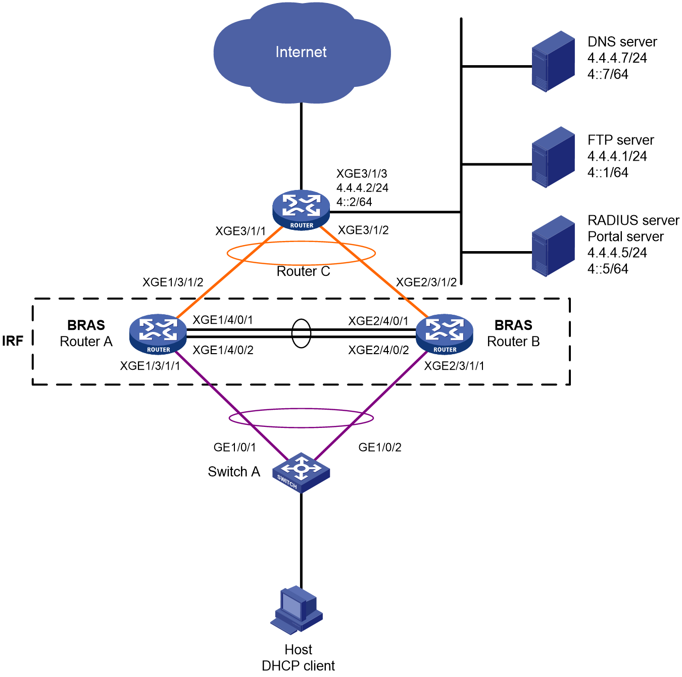
Table 12 IP address planning table
|
Device |
Interface |
IP address |
Device |
Interface |
IP address |
|
DNS server |
N/A |
4.4.4.7/24 4::7/64 |
IRF fabric (BRAS) |
RAGG1 |
N/A |
|
FTP server |
N/A |
4.4.4.1/24 4::1/64 |
|
RAGG1023 |
100.1.1.1/24 100::1/64 |
|
RADIUS server and portal server |
|
4.4.4.5/24 4::5/64 |
|
XGE1/3/1/1 |
N/A |
|
Router C |
RAGG1023 |
100.1.1.2/24 100::2/64 |
|
XGE2/3/1/1 |
N/A |
|
|
XGE3/1/1 |
N/A |
|
XGE1/3/1/2 |
N/A |
|
|
XGE3/1/2 |
N/A |
|
XGE2/3/1/2 |
N/A |
|
|
XGE3/1/3 |
4.4.4.2/24 4::2/64 |
|
LoopBack1 |
80.1.1.1/32 80::1/128 |
|
|
|
|
|
|
|
Analysis
· To prevent single points of failure from affecting normal service traffic forwarding, configure multichassis link aggregation on the IRF fabric for service traffic forwarding.
· To minimize the impacts of IRF split on services, configure LACP MAD on the IRF fabric. You only need to configure LACP MAD on one aggregate interface. LACP MAD requires an IRF-capable intermediate device running software that can recognize and process LACPDUs containing the ActiveID field. In this example, Switch A is used as the intermediate device for LACP MAD.
· To guarantee bandwidth for users, authorize CAR actions to users for rate limiting.
· For the inbound traffic in the IPoE Web preauthentication domain, configure the following traffic classes and behaviors:
¡ Configure a traffic class to match traffic destined for the DNS server in a user group that accommodates users in the preauthentication domain, and configure the filter permit traffic behavior accordingly. The user group that accommodates users in the preauthentication domain is referred to as the preauthentication user group for simplicity in this example.
¡ Configure a traffic class to match traffic destined for the portal server in the preauthentication user group, and configure the filter permit traffic behavior accordingly.
¡ Configure a traffic class to match traffic destined for the internal network server in the preauthentication user group, and configure the filter permit traffic behavior accordingly.
¡ Configure a traffic class to match HTTP traffic in the preauthentication user group, and configure the redirect http-to-cpu traffic behavior accordingly.
¡ Configure a traffic class to match HTTPS traffic in the preauthentication user group, and configure the redirect https-to-cpu traffic behavior accordingly.
¡ Configure a traffic class to match IP traffic in the preauthentication user group, and configure the redirect cpu traffic behavior accordingly. (The configuration is required only for transparent authentication.)
¡ Configure a traffic class to match IP traffic in the preauthentication user group, and configure the filter deny traffic behavior accordingly.
· For the outbound traffic in the IPoE Web preauthentication domain, configure the following traffic classes and behaviors:
¡ Configure a traffic class to match traffic from the DNS server in the preauthentication user group, and configure the filter permit traffic behavior accordingly.
¡ Configure a traffic class to match traffic from the portal server in the preauthentication user group, and configure the filter permit traffic behavior accordingly.
¡ Configure a traffic class to match traffic from the internal network server in the preauthentication user group, and configure the filter permit traffic behavior accordingly.
¡ Configure a traffic class to match IP traffic in the preauthentication user group, and configure the filter deny traffic behavior accordingly.
Restrictions and guidelines
To prevent port conflicts from causing service unavailability, make sure the listening port numbers are not well-known port numbers or port numbers used by other TCP-based services. To view the TCP port numbers already used by services, use the display tcp command.
In this example, DHCPv4 assigns IPv4 addresses to endpoints, and DHCPv6 assigns IPv6 addresses to endpoints. Once an endpoint passes authentication in one stack, it can access the network resources in both stacks. However, the configuration in this example might cause an Android phone failing to obtain an IPv6 address.
Procedure
Configuring IP addresses and routes
# On Router C, assign an IPv4 address and an IPv6 address to Ten-GigabitEthernet 3/1/3 (the interface connected to the servers).
<RouterC> system-view
[RouterC] interface ten-gigabitethernet 3/1/3
[RouterC-Ten-GigabitEthernet3/1/3] ip address 4.4.4.2 24
[RouterC-Ten-GigabitEthernet3/1/3] ipv6 address 4::2 64
[RouterC-Ten-GigabitEthernet3/1/3] quit
# On Router C, configure static routes destined for users.
[RouterC] ip route-static 192.168.0.0 24 100.1.1.1
[RouterC] ipv6 route-static 192:: 64 100::1
Configuring the DNS server
Configure the DNS server correctly so that the server can resolve the IPv4 or IPv6 URL address corresponding to the Web authentication page (in this example, http://www.ipv4.web.com and http://www.ipv6.web.com) based on the first protocol stack type used by a dual-stack IPoE user when the user comes online.
In this example, Windows Server 2016 is used to describe the basic DNS server configuration.
To configure the DNS server:
1. Install the DNS component:
a. Log in to the server, click Start, and then select Server Manager.
b. Click Add roles and features.
c. In the Before You Begin step, click Next.
d. In the Installation Type step, use the default setting, which is role-based or feature-based installation, and then click Next.
e. In the Server Selection step, use the default setting, which is Select a server from the server pool, and then click Next.
f. In the Server Roles step, select DNS Server. In the wizard window that opens, click Add Features, and then click Next.
g. In the Features step, use the default settings, and then click Next.
h. In the DNS Server step, click Next.
i. In the Confirmation step, click Install and wait for the installation to complete.
j. In the Results step, click Close.
2. Create an IPv4 forward lookup zone:
a. In the Server Manager window, click Tools, and then select DNS.
b. In the DNS Manager window, right click Forward Lookup Zones, and then select New Zone.
c. In the New Zone Wizard window, click Next.
d. In the Zone Type step, select Primary zone, and then click Next.
e. In the Zone Name step, enter zone name ipv4.web.com.
f. In the Zone File step, use the default settings, and then click Next.
g. In the Dynamic Update step, select Do not allow dynamic updates, and then click Next.
h. Click Finish.
i. In the DNS Manager window, click Forward Lookup Zones, right click ipv4.web.com, and then select New Host.
j. In the New Host window, enter host name www and IP address 4.4.4.7, and then click Add Host.
3. Create an IPv4 reverse lookup zone:
a. In the DNS Manager window, right click Reverse Lookup Zones, and then select New Zone.
b. In the New Zone Wizard window, click Next.
c. In the Zone Type step, select Primary zone, and then click Next.
d. In the Reverse Lookup Zone Name step, select IPv4 Reverse Lookup Zone, and then click Next.
e. Enter network ID 4.4.4, and then click Next.
f. In the Zone File step, use the default settings, and then click Next.
g. In the Dynamic Update step, select Do not allow dynamic updates, and then click Next.
h. Click Finish.
i. In the DNS Manager window, click Reverse Lookup Zones, right click 4.4.4.in-addr.arpa.dns, and then select New Pointer.
j. In the New Resource Record window, enter host IP address 4.4.4.7 and host name www.ipv4.web.com, and then click OK.
4. Create an IPv6 forward lookup zone:
a. In the Server Manager window, click Tools, and then select DNS.
b. In the DNS Manager window, right click Forward Lookup Zones, and then select New Zone.
c. In the New Zone Wizard window, click Next.
d. In the Zone Type step, select Primary zone, and then click Next.
e. In the Zone Name step, enter zone name ipv6.web.com.
f. In the Zone File step, use the default settings, and then click Next.
g. In the Dynamic Update step, select Do not allow dynamic updates, and then click Next.
h. Click Finish.
i. In the DNS Manager window, click Forward Lookup Zones, right click ipv6.web.com, and then select New Host.
j. In the New Host window, enter host name www and IP address 4::7, and then click Add Host.
5. Create an IPv6 reverse lookup zone:
a. In the DNS Manager window, right click Reverse Lookup Zones, and then select New Zone.
b. In the New Zone Wizard window, click Next.
c. In the Zone Type step, select Primary zone, and then click Next.
d. In the Reverse Lookup Zone Name step, select IPv6 Reverse Lookup Zone, and then click Next.
e. Enter network ID 4000:0000:0000:0000::/64, and then click Next.
f. In the Zone File step, use the default settings, and then click Next.
g. In the Dynamic Update step, select Do not allow dynamic updates, and then click Next.
h. Click Finish.
i. In the DNS Manager window, click Reverse Lookup Zones, right click 0.0.0.0.0.0.0.0.0.0.0.0.0.0.0.4.in-addr.arpa.dns, and then select New Pointer.
j. In the New Resource Record window, enter host IP address 4000.0000.0000.0000.0000.0000.0000.0007 and host name www.ipv6.web.com, and then click OK.
Configuring the RADIUS server and portal server
In this example, Srun 4.0.9 is installed on the server.
To configure the RADIUS server and portal server:
1. Enter http://4.4.4.5:8081 in the address bar of a Web browser, log in to the server, and add an access device:
# Open the page for managing devices, click the tab for adding devices, and add a device.
¡ Set the device name to BRAS.
¡ Use the IP address of Loopback 1 on the BRAS device as the NAS IP address. In this example, the IP address is 80.1.1.1.
¡ Use IP address 4.4.4.5 as ours IP address.
¡ Select NAS types Huawei, H3C, and Srun gateway.
¡ Set the DM port to 3799.
¡ Set the RADIUS key to 123456.
¡ Select to not discard traffic.
¡ Select H3C and Huawei (h3c v1.2) as the portal protocols.
¡ Set the portal key to 123456.
# Configure RADIUS trust settings:
a. Enter the RADIUS page, and click the link for accessing the RADIUS trust settings page.
b. On the page, continuously click Generate in the upper right corner until the generation succeeds.
c. Restart the Srun RADIUS process.
# Click the tab for configuring RADIUS service settings, and configure the system to validate usernames with the domain name.
2. Enter https://4.4.4.5:8080 in the address bar of a Web browser, log in to the server, and add a user:
a. Click the tab for managing and adding users, and then add a user.
b. Set the account name to user1 and the password to pass.
3. To deploy other settings such as control policies and product policies, see the manuals for the Srun server.
Setting up an IRF fabric
1. Use Router A and Router B to set up an IRF fabric:
# Assign member ID 1 to Router A, and bind Ten-GigabitEthernet 4/0/1 and Ten-GigabitEthernet 4/0/2 to IRF-port 2.
<RouterA> system-view
[RouterA] irf member 1 priority 2
[RouterA] interface ten-gigabitethernet 4/0/1
[RouterA-Ten-GigabitEthernet4/0/1] port link-mode bridge
[RouterA-Ten-GigabitEthernet4/0/1] quit
[RouterA] interface ten-gigabitethernet 4/0/2
[RouterA-Ten-GigabitEthernet4/0/2] port link-mode bridge
[RouterA-Ten-GigabitEthernet4/0/2] quit
[RouterA] irf-port 2
[RouterA-irf-port2] port group interface ten-gigabitethernet 4/0/1
[RouterA-irf-port2] port group interface ten-gigabitethernet 4/0/2
[RouterA-irf-port2] quit
# Save the running configuration to the main next-startup configuration file.
[RouterA] quit
<RouterA> save
# Enable IRF mode.
<RouterA> system-view
[RouterA] chassis convert mode irf
The device will switch to IRF mode and reboot. Continue?[Y/N]:y
You are recommended to save the current running configuration and specify the configuration file for the next startup. Now save the running configuration to the next-startup configuration file? [Y/N]:y
Please input the file name(*.cfg)[cfa0:/test.cfg]
(To leave the existing filename unchanged, press the enter key):
cfa0:/test.cfg exists, overwrite? [Y/N]:y
Validating file. Please wait...
Saved the current configuration to mainboard device successfully.
Do you want to convert the content of the next startup configuration file cfa0:/test.cfg to make it available in IRF mode? [Y/N]:y
Now rebooting, please wait...
A single-member IRF fabric that contains only Router A is set up after the router reboots.
# Assign member ID 2 to Router B, and bind Ten-GigabitEthernet 4/0/1 and Ten-GigabitEthernet 4/0/2 to IRF-port 1.
<RouterB> system-view
[RouterB] irf member 2 priority 1
[RouterB] interface ten-gigabitethernet 4/0/1
[RouterB-Ten-GigabitEthernet4/0/1] port link-mode bridge
[RouterB-Ten-GigabitEthernet4/0/1] quit
[RouterB] interface ten-gigabitethernet 4/0/2
[RouterB-Ten-GigabitEthernet4/0/2] port link-mode bridge
[RouterB-Ten-GigabitEthernet4/0/2] quit
[RouterB] irf-port 1
[RouterB-irf-port1] port group interface ten-gigabitethernet 4/0/1
[RouterB-irf-port1] port group interface ten-gigabitethernet 4/0/2
[RouterB-irf-port1] quit
# Save the running configuration to the main next-startup configuration file.
[RouterB] quit
<RouterB> save
# Enable IRF mode.
<RouterB> system-view
[RouterB] chassis convert mode irf
The device will switch to IRF mode and reboot. Continue?[Y/N]:y
You are recommended to save the current running configuration and specify the configuration file for the next startup. Now save the running configuration to the next-startup configuration file? [Y/N]:y
Please input the file name(*.cfg)[cfa0:/test.cfg]
(To leave the existing filename unchanged, press the enter key):
cfa0:/test.cfg exists, overwrite? [Y/N]:y
Validating file. Please wait...
Saved the current configuration to mainboard device successfully.
Do you want to convert the content of the next startup configuration file cfa0:/test.cfg to make it available in IRF mode? [Y/N]:y
Now rebooting, please wait...
Router B joins the IRF fabric that contains Router A after it reboots.
2. Configure downlink services for the IRF fabric:
a. Configure LACP MAD:
In this example, Router A acts as the master device in the IRF fabric and acts as a BRAS device in IPoE. For ease of understanding, Router A will be referred to as IRF in the subsequent IRF configuration steps and as BRAS in the subsequent IPoE configuration steps.
After the IRF fabric is established, you can configure settings for service modules. Once the IRF fabric is established, you can log in to the IRF fabric from any member device for configuration. By default, the device name of the IRF fabric is the name of the master device. In this example, the master device is Router A.
# Create Route-Aggregation 1 (the Layer 3 aggregate interface connected to Switch A), configure the aggregation group to operate in dynamic aggregation mode, and enable LACP MAD on the aggregate interface.
<IRF> system-view
[IRF] interface route-aggregation 1
[IRF-Route-Aggregation1] link-aggregation mode dynamic
[IRF-Route-Aggregation1] mad enable
You need to assign a domain ID (range: 0-4294967295)
[Current domain is: 0]:
The assigned domain ID is: 0
MAD LACP only enable on dynamic aggregation interface.
[IRF-Route-Aggregation1] quit
# Assign interfaces connected to Switch A to Layer 3 aggregation group 1.
[IRF] interface ten-gigabitethernet 1/3/1/1
[IRF-Ten-GigabitEthernet1/3/1/1] port link-aggregation group 1
[IRF-Ten-GigabitEthernet1/3/1/1] quit
[IRF] interface ten-gigabitethernet 2/3/1/1
[IRF-Ten-GigabitEthernet2/3/1/1] port link-aggregation group 1
[IRF-Ten-GigabitEthernet2/3/1/1] quit
b. Configure Switch A:
# Create Bridge-Aggregation 1 (the Layer 2 aggregate interface connected to the IRF fabric), and configure the aggregation group to operate in dynamic aggregation mode. The aggregate interface will be used for IRF LACP MAD.
<SwitchA> system-view
[SwitchA] interface bridge-aggregation 1
[SwitchA-Bridge-Aggregation1] link-aggregation mode dynamic
[SwitchA-Bridge-Aggregation1] quit
# Assign interfaces connected to the IRF fabric to Layer 2 aggregation group 1.
[SwitchA] interface gigabitethernet 1/0/1
[SwitchA-GigabitEthernet1/0/1] port link-aggregation group 1
[SwitchA-GigabitEthernet1/0/1] quit
[SwitchA] interface gigabitethernet 1/0/2
[SwitchA-GigabitEthernet1/0/2] port link-aggregation group 1
[SwitchA-GigabitEthernet1/0/2] quit
3. Configure uplink services for the IRF fabric:
a. Configure aggregation group settings on the IRF fabric:
# Create Route-Aggregation 1023 (the Layer 3 aggregate interface connected to Router C), configure the aggregation group to operate in dynamic aggregation mode, and assign an IPv4 address and an IPv6 address to the aggregate interface.
[IRF] interface route-aggregation 1023
[IRF-Route-Aggregation1023] link-aggregation mode dynamic
[IRF-Route-Aggregation1023] ip address 100.1.1.1 24
[IRF-Route-Aggregation1023] ipv6 address 100::1 64
[IRF-Route-Aggregation1023] quit
# Assign interfaces connected to Router C to Layer 3 aggregation group 1023.
[IRF] interface ten-gigabitethernet 1/3/1/2
[IRF-Ten-GigabitEthernet1/3/1/2] port link-aggregation group 1023
[IRF-Ten-GigabitEthernet1/3/1/2] quit
[IRF] interface ten-gigabitethernet 2/3/1/2
[IRF-Ten-GigabitEthernet2/3/1/2] port link-aggregation group 1023
[IRF-Ten-GigabitEthernet2/3/1/2] quit
# Configure static routes destined for Router C (for accessing servers and the Internet).
[IRF] ip route-static 0.0.0.0 0 100.1.1.2
[IRF] ipv6 route-static :: 0 100::2
b. Configure Router C:
In this example, the configuration steps only cover the IRF-side settings. The routing protocol used for the external network is not described.
# Create Route-Aggregation 1023 (the Layer 3 aggregate interface connected to the IRF fabric), configure the aggregation group to operate in dynamic aggregation mode, and assign an IPv4 address and an IPv6 address to the aggregate interface.
<RouterC> system-view
[RouterC] interface route-aggregation 1023
[RouterC-Route-Aggregation1023] link-aggregation mode dynamic
[RouterC-Route-Aggregation1023] ip address 100.1.1.2 24
[RouterC-Route-Aggregation1023] ipv6 address 100::2 64
[RouterC-Route-Aggregation1023] quit
# Assign interfaces connected to the IRF fabric to Layer 3 aggregation group 1023.
[RouterC] interface ten-gigabitethernet 3/1/1
[RouterC-Ten-GigabitEthernet3/1/1] port link-aggregation group 1023
[RouterC-Ten-GigabitEthernet3/1/1] quit
[RouterC] interface ten-gigabitethernet 3/1/2
[RouterC-Ten-GigabitEthernet3/1/2] port link-aggregation group 1023
[RouterC-Ten-GigabitEthernet3/1/2] quit
Configuring BRAS settings
1. Configure the DHCP server:
a. Configure an IPv4 address pool:
# Enable DHCP.
<BRAS> system-view
[BRAS] dhcp enable
# Enable the DHCP server to return a DHCP-NAK message if the client notions of their IP addresses are incorrect.
[BRAS] dhcp server request-ip-address check
# Create an IPv4 address pool named pool1 and enter its view.
[BRAS] ip pool pool1
# Specify primary subnet 192.168.0.0/24 for dynamic allocation and DNS server 4.4.4.7 in address pool pool1.
[BRAS-ip-pool-pool1] network 192.168.0.0 24 export-route
[BRAS-ip-pool-pool1] dns-list 4.4.4.7
# Specify gateway address 192.168.0.1 in address pool pool1.
[BRAS-ip-pool-pool1] gateway-list 192.168.0.1 export-route
# Exclude IP address 192.168.0.1 from dynamic allocation in address pool pool1.
[BRAS-ip-pool-pool1] forbidden-ip 192.168.0.1
[BRAS-ip-pool-pool1] quit
b. Configure an IPv6 address pool:
# Create an IPv6 address pool named pool2 and enter its view.
[BRAS] ipv6 pool pool2
# Specify primary subnet 192::/64 for dynamic allocation, gateway address 192::1, and DNS server 4::7 in address pool pool2.
[BRAS-ipv6-pool-pool2] network 192::/64 export-route
[BRAS-ipv6-pool-pool2] gateway-list 192::1
[BRAS-ipv6-pool-pool2] dns-server 4::7
[BRAS-ipv6-pool-pool2] quit
# Exclude IP address 192::1 from dynamic allocation in address pool pool2.
[BRAS] ipv6 dhcp server forbidden-address 192::1
# Enable the DHCPv6 server on Route-Aggregation 1. (By default, the DHCPv4 server is enabled on an interface.)
[BRAS] interface route-aggregation 1
[BRAS–Route-Aggregation1] ipv6 dhcp select server
# Configure the interface gateway address.
[BRAS–Route-Aggregation1] ip address 192.168.0.1 255.255.255.0
[BRAS–Route-Aggregation1] ipv6 address 192::1/64
# Disable RA message suppression on Route-Aggregation 1. Set the managed address configuration flag (M) to 1 in RA advertisements to be sent. Then, the host uses a DHCPv6 server to obtain IPv6 addresses. Set the other stateful configuration flag (O) to 1 in RA advertisements to be sent. Then, the host uses a DHCPv6 server to obtain configuration information other than IPv6 addresses.
[BRAS–Route-Aggregation1] undo ipv6 nd ra halt
[BRAS–Route-Aggregation1] ipv6 nd autoconfig managed-address-flag
[BRAS–Route-Aggregation1] ipv6 nd autoconfig other-flag
# Disable Route-Aggregation 1 from advertising the specified prefix in RA messages, preventing the endpoint from obtaining a temporary IPv6 address. In an IPv6 network, an endpoint might use a temporary IPv6 address for IPoE Web authentication, which will cause authentication failure.
[BRAS–Route-Aggregation1] ipv6 nd ra prefix 192::/64 no-advertise
[BRAS–Route-Aggregation1] quit
2. Configure the portal authentication server:
# Create an IPv4 portal authentication server named newpt1, configure its IP address as 4.4.4.5, and set its key to 123456 in plaintext form.
[BRAS] portal server newpt1
[BRAS-portal-server-newpt1] ip 4.4.4.5 key simple 123456
[BRAS-portal-server-newpt1] quit
# Create an IPv6 portal authentication server named newpt2, configure its IPv6 address as 4::5, and set its key to 123456 in plaintext form.
[BRAS] portal server newpt2
[BRAS-portal-server-newpt2] ipv6 4::5 key simple 123456
[BRAS-portal-server-newpt2] quit
3. Configure the HTTPS redirect listening port number:
# Specify 11111 as the HTTPS redirect listening port number. Make sure the port number is not used by any other service. To see the TCP port numbers used by other services, execute the display tcp command.
[BRAS] http-redirect https-port 11111
4. Configure the BRAS to get user access information from ARP and ND entries:
# Configure the BRAS to get user access information from ARP and ND entries.
[BRAS] portal access-info trust arp
[BRAS] portal access-info trust nd
5. Create a local user group:
# Create a user group named pre for preauthentication.
[BRAS] user-group pre
New user group added.
[BRAS-ugroup-pre] quit
6. Configure QoS settings:
a. Configure ACLs for preauthentication:
# Create an IPv4 and IPv6 advanced ACL named dns_permit separately. Configure a rule to permit all packets destined for the DNS server from users in user group pre.
[BRAS] acl advanced name dns_permit
[BRAS-acl-ipv4-adv-dns_permit] rule 0 permit ip destination 4.4.4.7 0 user-group pre
[BRAS-acl-ipv4-adv-dns_permit] quit
[BRAS] acl ipv6 advanced name dns_permit
[BRAS-acl-ipv6-adv-dns_permit] rule 0 permit ipv6 destination 4::7 128 user-group pre
[BRAS-acl-ipv6-adv-dns_permit] quit
# Create an IPv4 and IPv6 advanced ACL named web_permit separately. Configure a rule to permit all packets destined for the portal server from users in user group pre.
[BRAS] acl advanced name web_permit
[BRAS-acl-ipv4-adv-web_permit] rule 0 permit ip destination 4.4.4.5 0 user-group pre
[BRAS-acl-ipv4-adv-web_permit] quit
[BRAS] acl ipv6 advanced name web_permit
[BRAS-acl-ipv6-adv-web_permit] rule 0 permit ipv6 destination 4::5 128 user-group pre
[BRAS-acl-ipv6-adv-web_permit] quit
# Create an IPv4 and IPv6 advanced ACL named neiwang separately. Configure a rule to permit all packets destined for the internal network server from users in user group pre.
[BRAS] acl advanced name neiwang
[BRAS-acl-ipv4-adv-neiwang] rule 0 permit ip destination 4.4.4.1 0 user-group pre
[BRAS-acl-ipv4-adv-neiwang] quit
[BRAS] acl ipv6 advanced name neiwang
[BRAS-acl-ipv6-adv-neiwang] rule 0 permit ipv6 destination 4::1 128 user-group pre
[BRAS-acl-ipv6-adv-neiwang] quit
# Create an IPv4 and IPv6 advanced ACL named web_http separately. Configure a rule to permit TCP packets with the destination port 80 (HTTP packets) from users in user group pre.
[BRAS] acl advanced name web_http
[BRAS-acl-ipv4-adv-web_http] rule 0 permit tcp destination-port eq www user-group pre
[BRAS-acl-ipv4-adv-web_http] quit
[BRAS] acl ipv6 advanced name web_http
[BRAS-acl-ipv6-adv-web_http] rule 0 permit tcp destination-port eq www user-group pre
[BRAS-acl-ipv6-adv-web_http] quit
# Create an IPv4 and IPv6 advanced ACL named web_https separately, and configure a rule to permit TCP packets with the destination port 443 (HTTPS packets) from users in user group pre.
[BRAS] acl advanced name web_https
[BRAS-acl-ipv4-adv-web_https] rule 0 permit tcp destination-port eq 443 user-group pre
[BRAS-acl-ipv4-adv-web_https] quit
[BRAS] acl ipv6 advanced name web_https
[BRAS-acl-ipv6-adv-web_https] rule 0 permit tcp destination-port eq 443 user-group pre
[BRAS-acl-ipv6-adv-web_https] quit
# Create an IPv4 and IPv6 advanced ACL named ip separately, and configure a rule to permit IP packets from users in user group pre.
[BRAS] acl advanced name ip
[BRAS-acl-ipv4-adv-ip] rule 0 permit ip user-group pre
[BRAS-acl-ipv4-adv-ip] quit
[BRAS] acl ipv6 advanced name ip
[BRAS-acl-ipv6-adv-ip] rule 0 permit ipv6 user-group pre
[BRAS-acl-ipv6-adv-ip] quit
# Create an IPv4 and IPv6 advanced ACL named neiwang_out separately, and configure a rule to permit IP packets from the internal network server in user group pre.
[BRAS] acl advanced name neiwang_out
[BRAS-acl-ipv4-adv-neiwang_out] rule 0 permit ip source 4.4.4.1 0 user-group pre
[BRAS-acl-ipv4-adv-neiwang_out] quit
[BRAS] acl ipv6 advanced name neiwang_out
[BRAS-acl-ipv6-adv-neiwang_out] rule 0 permit ipv6 source 4::1 128 user-group pre
[BRAS-acl-ipv6-adv-neiwang_out] quit
# Create an IPv4 and IPv6 advanced ACL named web_out separately, and configure a rule to permit IP packets from the portal server in user group pre.
[BRAS] acl advanced name web_out
[BRAS-acl-ipv4-adv-web_out] rule 0 permit ip source 4.4.4.5 0 user-group pre
[BRAS-acl-ipv4-adv-web_out] quit
[BRAS] acl ipv6 advanced name web_out
[BRAS-acl-ipv6-adv-web_out] rule 0 permit ipv6 source 4::5 128 user-group pre
[BRAS-acl-ipv6-adv-web_out] quit
# Create an IPv4 and IPv6 advanced ACL named dns_out separately, and configure a rule to permit IP packets from the DNS server in user group pre.
[BRAS] acl advanced name dns_out
[BRAS-acl-ipv4-adv-dns_out] rule 0 permit ip source 4.4.4.7 0 user-group pre
[BRAS-acl-ipv4-adv-dns_out] quit
[BRAS] acl ipv6 advanced name dns_out
[BRAS-acl-ipv6-adv-dns_out] rule 0 permit ipv6 source 4::7 128 user-group pre
[BRAS-acl-ipv6-adv-dns_out] quit
b. Configure QoS traffic classes for preauthentication users:
# Create traffic class dns_permit and specify ACL dns_permit as the match criterion.
[BRAS] traffic classifier dns_permit operator or
[BRAS-classifier-dns_permit] if-match acl name dns_permit
[BRAS-classifier-dns_permit] if-match acl ipv6 name dns_permit
[BRAS-classifier-dns_permit] quit
# Create traffic class web_permit and specify ACL web_permit as the match criterion.
[BRAS] traffic classifier web_permit operator or
[BRAS-classifier-web_permit] if-match acl name web_permit
[BRAS-classifier-web_permit] if-match acl ipv6 name web_permit
[BRAS-classifier-web_permit] quit
# Create traffic class neiwang and specify ACL neiwang as the match criterion.
[BRAS] traffic classifier neiwang operator or
[BRAS-classifier-neiwang] if-match acl name neiwang
[BRAS-classifier-neiwang] if-match acl ipv6 name neiwang
[BRAS-classifier-neiwang] quit
# Create traffic class web_http and specify ACL web_http as the match criterion.
[BRAS] traffic classifier web_http operator or
[BRAS-classifier-web_http] if-match acl name web_http
[BRAS-classifier-web_http] if-match acl ipv6 name web_http
[BRAS-classifier-web_http] quit
# Create traffic class web_https and specify ACL web_https as the match criterion.
[BRAS] traffic classifier web_https operator or
[BRAS-classifier-web_https] if-match acl name web_https
[BRAS-classifier-web_https] if-match acl ipv6 name web_https
[BRAS-classifier-web_https] quit
# Create traffic class web_deny and specify ACL ip as the match criterion.
[BRAS] traffic classifier web_deny operator or
[BRAS-classifier-web_deny] if-match acl name ip
[BRAS-classifier-web_deny] if-match acl ipv6 name ip
[BRAS-classifier-web_deny] quit
# Create traffic class neiwang_out and specify ACL neiwang_out as the match criterion.
[BRAS] traffic classifier neiwang_out operator or
[BRAS-classifier-neiwang_out] if-match acl name neiwang_out
[BRAS-classifier-neiwang_out] if-match acl ipv6 name neiwang_out
[BRAS-classifier-neiwang_out] quit
# Create traffic class web_out and specify ACL web_out as the match criterion.
[BRAS] traffic classifier web_out operator or
[BRAS-classifier-web_out] if-match acl name web_out
[BRAS-classifier-web_out] if-match acl ipv6 name web_out
[BRAS-classifier-web_out] quit
# Create traffic class dns_out and specify ACL dns_out as the match criterion.
[BRAS] traffic classifier dns_out operator or
[BRAS-classifier-dns_out] if-match acl name dns_out
[BRAS-classifier-dns_out] if-match acl ipv6 name dns_out
[BRAS-classifier-dns_out] quit
c. Configure QoS traffic behaviors:
# Configure traffic behavior dns_permit to permit traffic to pass through without rate limiting or accounting.
[BRAS] traffic behavior dns_permit
[BRAS-behavior-dns_permit] filter permit
[BRAS-behavior-dns_permit] free account
[BRAS-behavior-dns_permit] quit
# Configure traffic behavior web_permit to permit traffic to pass through without rate limiting or accounting.
[BRAS] traffic behavior web_permit
[BRAS-behavior-web_permit] filter permit
[BRAS-behavior-web_permit] free account
[BRAS-behavior-web_permit] quit
# Configure traffic behavior neiwang to permit traffic to pass through without rate limiting or accounting.
[BRAS] traffic behavior neiwang
[BRAS-behavior-neiwang] filter permit
[BRAS-behavior-neiwang] free account
[BRAS-behavior-neiwang] quit
# Configure traffic behavior web_http to redirect HTTP packets to the CPU.
[BRAS] traffic behavior web_http
[BRAS-behavior-web_http] redirect http-to-cpu
[BRAS-behavior-web_http] quit
# Configure traffic behavior web_https to redirect HTTPS packets to the CPU.
[BRAS] traffic behavior web_https
[BRAS-behavior-web_https] redirect https-to-cpu
[BRAS-behavior-web_https] quit
# Configure traffic behavior web_deny to deny traffic.
[BRAS] traffic behavior web_deny
[BRAS-behavior-web_deny] filter deny
[BRAS-behavior-web_deny] free account
[BRAS-behavior-web_deny] quit
# Configure traffic behavior neiwang_out to permit traffic to pass through without rate limiting or accounting.
[BRAS] traffic behavior neiwang_out
[BRAS-behavior-neiwang_out] filter permit
[BRAS-behavior-neiwang_out] free account
[BRAS-behavior-neiwang_out] quit
# Configure traffic behavior web_out to permit traffic to pass through without rate limiting or traffic accounting.
[BRAS] traffic behavior web_out
[BRAS-behavior-web_out] filter permit
[BRAS-behavior-web_out] free account
[BRAS-behavior-web_out] quit
# Configure traffic behavior dns_out to permit traffic to pass through without rate limiting or traffic accounting.
[BRAS] traffic behavior dns_out
[BRAS-behavior-dns_out] filter permit
[BRAS-behavior-dns_out] free account
[BRAS-behavior-dns_out] quit
d. Configure QoS policies:
Create a QoS policy named web.
[BRAS] qos policy web
# Associate traffic classes with traffic behaviors to
permit packets destined for the DNS server, portal server, and internal network server to pass through and
redirect packets with destination port 80 (HTTP packets) and packets with destination port 443 (HTTPS packets) to the CPU.
All other packets are denied.
[BRAS-qospolicy-web] classifier dns_permit behavior dns_permit
[BRAS-qospolicy-web] classifier web_permit behavior web_permit
[BRAS-qospolicy-web] classifier neiwang behavior neiwang
[BRAS-qospolicy-web] classifier web_http behavior web_http
[BRAS-qospolicy-web] classifier web_https behavior web_https
[BRAS-qospolicy-web] classifier web_deny behavior web_deny
[BRAS-qospolicy-web] quit
# Create a QoS policy named out.
[BRAS] qos policy out
# Associate traffic classes with traffic behaviors to permit packets from the DNS server, portal server, and internal network server in user group pre to pass through. All other packets are denied.
[BRAS-qospolicy-out] classifier dns_out behavior dns_out
[BRAS-qospolicy-out] classifier web_out behavior web_out
[BRAS-qospolicy-out] classifier neiwang_out behavior neiwang_out
[BRAS-qospolicy-out] classifier web_deny behavior web_deny
[BRAS-qospolicy-out] quit
e. Apply the QoS policies:
# Apply QoS policy web to the inbound traffic globally. To identify whether the QoS policy takes effect, execute the display qos policy global inbound command.
[BRAS] qos apply policy web global inbound
# Apply QoS policy out to the outbound traffic globally. To identify whether the QoS policy takes effect, execute the display qos policy global outbound command.
[BRAS] qos apply policy out global outbound
7. Configure a RADIUS scheme:
# Create a RADIUS scheme named rs1 and enter its view.
[BRAS] radius scheme rs1
# Configure primary servers and keys for authentication and accounting.
[BRAS-radius-rs1] primary authentication 4.4.4.5
[BRAS-radius-rs1] primary accounting 4.4.4.5
[BRAS-radius-rs1] key authentication simple 123456
[BRAS-radius-rs1] key accounting simple 123456
# Exclude the ISP domain name from the usernames sent to the RADIUS servers.
[BRAS-radius-rs1] user-name-format without-domain
# Set the IPv4 NAS-IP address carried in RADIUS packets to 80.1.1.1.
[BRAS-radius-rs1] nas-ip 80.1.1.1
[BRAS-radius-rs1] quit
# Specify the RADIUS DAE client at 4.4.4.5, and set the shared key to 123456 in plaintext form for secure communication between the DAE server and client. Make sure the shared key is the same as the key configured on the RADIUS DAE client.
[BRAS] radius dynamic-author server
[BRAS-radius-da-server] client ip 4.4.4.5 key simple 123456
[BRAS-radius-da-server] quit
8. Configure the preauthentication ISP domain and Web authentication ISP domain:
# Configure ISP domain dm1 for IPoE user preauthentication.
[BRAS] domain name dm1
[BRAS-isp-dm1] authentication ipoe none
[BRAS-isp-dm1] authorization ipoe none
[BRAS-isp-dm1] accounting ipoe none
# Configure the authorization user group in preauthentication ISP domain dm1.
[BRAS-isp-dm1] authorization-attribute user-group pre
# Configure the Web authentication page URLs in ISP domain dm1.
[BRAS-isp-dm1] web-server url http://www.ipv4.web.com
[BRAS-isp-dm1] web-server ipv6-url http://www.ipv6.web.com
[BRAS-isp-dm1] quit
# Configure ISP domain dm2 for IPoE user Web authentication.
[BRAS] domain name dm2
[BRAS-isp-dm2] authentication ipoe radius-scheme rs1
[BRAS-isp-dm2] authorization ipoe radius-scheme rs1
[BRAS-isp-dm2] accounting ipoe radius-scheme rs1
[BRAS-isp-dm2] authorization-attribute car inbound cir 5120 outbound cir 5120
[BRAS-isp-dm2] quit
9. Configure IPoE:
# Enable IPoE and configure the Layer 2 access mode for users on Route-Aggregation 1.
[BRAS] interface route-aggregation 1
[BRAS–Route-Aggregation1] ip subscriber l2-connected enable
# Configure the Web authentication method for IPoE users on Route-Aggregation 1.
[BRAS–Route-Aggregation1] ip subscriber authentication-method web
The operation may cut all users on this interface. Continue?[Y/N]:y
# Specify ISP domain dm1 as the Web preauthentication domain and ISP domain dm2 as the Web authentication domain on Route-Aggregation 1.
[BRAS–Route-Aggregation1] ip subscriber pre-auth domain dm1
[BRAS–Route-Aggregation1] ip subscriber web-auth domain dm2
# Enable unclassified-IPv4 packet initiation and unclassified-IPv6 packet initiation with the matching-user keyword specified. Enable ARP packet initiation and NS/NA packet initiation.
[BRAS–Route-Aggregation1] ip subscriber initiator unclassified-ip enable matching-user
[BRAS–Route-Aggregation1] ip subscriber initiator unclassified-ipv6 enable matching-user
[BRAS–Route-Aggregation1] ip subscriber initiator arp enable
[BRAS–Route-Aggregation1] ip subscriber initiator nsna enable
[BRAS–Route-Aggregation1] quit
10. Configure attack defense:
¡ Configure source MAC-based ARP attack detection:
# Enable source MAC-based ARP attack detection and specify the filter handling method.
[BRAS] arp source-mac filter
Set the check interval for source MAC-based ARP attack detection to 5 seconds.
[BRAS] arp source-mac check-interval 5
# Set the threshold for source MAC-based ARP attack detection to 30.
[BRAS] arp source-mac threshold 30
# Set the aging time for ARP attack entries to 300 seconds.
[BRAS] arp source-mac aging-time 300
¡ Configure source MAC-based ND attack detection:
# Enable source MAC-based ND attack detection and specify the filter handling method.
[BRAS] ipv6 nd source-mac filter
# Set the check interval for source MAC-based ND attack detection to 5 seconds.
[BRAS] ipv6 nd source-mac check-interval 5
# Set the threshold for source MAC-based ND attack detection to 30.
[BRAS] ipv6 nd source-mac threshold 30
# Set the aging time for ND attack entries to 300 seconds.
[BRAS] ipv6 nd source-mac aging-time 300
¡ Configure DHCP flood attack protection:
# Enable DHCP flood attack protection on Route-Aggregation 1.
[BRAS] interface route-aggregation 1
[BRAS-Route-Aggregation1] dhcp flood-protection enable
[BRAS–Route-Aggregation1] quit
# Configure the device to allow a maximum of 30 DHCP packets per 10000 milliseconds from each DHCP client.
[BRAS] dhcp flood-protection threshold 30 10000
# Set the DHCP flood attack entry aging time to 300 seconds.
[BRAS] dhcp flood-protection aging-time 300
¡ Configure DHCPv6 flood attack protection:
# Enable DHCPv6 flood attack protection on Route-Aggregation 1.
[BRAS] interface route-aggregation 1
[BRAS-Route-Aggregation1] ipv6 dhcp flood-protection enable
[BRAS-Route-Aggregation1] quit
# Configure the device to allow a maximum of 30 DHCPv6 packets per 10000 milliseconds from each DHCPv6 client.
[BRAS] ipv6 dhcp flood-protection threshold 30 10000
# Set the DHCPv6 flood attack entry aging time to 300 seconds.
[BRAS] ipv6 dhcp flood-protection aging-time 300
¡ Enable ICMP/ICMPv6 fast reply.
[BRAS] ip icmp fast-reply enable
[BRAS] ipv6 icmpv6 fast-reply enable
¡ Configure TCP SYN flood attack prevention:
# Enable flow-based TCP SYN flood attack prevention.
[BRAS] tcp anti-syn-flood flow-based enable
# Set the check interval to 20 seconds for flow-based TCP SYN flood attack prevention.
[BRAS] tcp anti-syn-flood flow-based check-interval 20
# Set the threshold to 2000 for triggering flow-based TCP SYN flood attack prevention.
[BRAS] tcp anti-syn-flood flow-based threshold 2000
# Set the flow-based TCP SYN flood attack prevention duration to 5 minutes.
[BRAS] tcp anti-syn-flood flow-based duration 5
¡ Configure HTTP/HTTPS attack defense:
# Enable destination IP-based IPoE HTTP/HTTPS attack defense.
[BRAS] ip subscriber http-defense destination-ip enable
# Trigger attack defense when the total number of HTTP/HTTPS packets sent to the same destination IP address within 300 seconds reaches 6000.
[BRAS] ip subscriber http-defense destination-ip threshold 6000 interval 300
¡ Enable HTTP packet fast reply:
# Enable HTTP packet fast reply on Route-Aggregation 1.
[BRAS] interface route-aggregation 1
[BRAS-Route-Aggregation1] ip subscriber http-fast-reply enable
[BRAS-Route-Aggregation1] quit
Verifying the configuration
# After the user passes authentication in the preauthentication domain, display information about online IPoE users to verify that the user has come online and obtained IPv4 address 192.168.0.2 and IPv6 address 192::2.
[BRAS] display access-user interface route-aggregation 1
UserID Interface IP address MAC address S-/C-VLAN
Username Access type
IPv6 address
0x5c RAGG1 192.168.0.2 000c-29a6-b656 -/-
000c29a6b656 L2 IPoE dynamic
192::2
# On the Web authentication page, enter the username and password, and then bring the user online. After the user passes Web authentication, display information about online IPoE users.
[BRAS] display access-user interface route-aggregation 1
UserID Interface IP address MAC address S-/C-VLAN
Username Access type
IPv6 address
0x5c RAGG1 192.168.0.2 000c-29a6-b656 -/-
user1 Web auth
192::2
Configuration files
· Router C:
#
interface Route-Aggregation1023
ip address 100.1.1.2 255.255.255.0
ipv6 address 100::2/64
link-aggregation mode dynamic
#
interface Ten-GigabitEthernet3/1/1
port link-aggregation group 1023
#
interface Ten-GigabitEthernet3/1/2
port link-aggregation group 1023
#
interface Ten-GigabitEthernet3/1/3
ip address 4.4.4.2 255.255.255.0
ipv6 address 4::2/64
#
ip route-static 192.168.0.0 24 100.1.1.1
ipv6 route-static 192:: 64 100::1
#
· IRF fabric (BRAS):
#
irf mac-address persistent always
irf auto-update enable
irf auto-merge enable
undo irf link-delay
irf member 1 priority 2
irf member 2 priority 1
#
irf-port 1/2
port group interface Ten-GigabitEthernet1/4/0/1 mode enhanced
port group interface Ten-GigabitEthernet1/4/0/2 mode enhanced
#
irf-port 2/1
port group interface Ten-GigabitEthernet2/4/0/1 mode enhanced
port group interface Ten-GigabitEthernet2/4/0/2 mode enhanced
#
dhcp enable
#
dhcp server request-ip-address check
#
ipv6 dhcp server forbidden-address 192::1
#
ip pool pool1
gateway-list 192.168.0.1 export-route
network 192.168.0.0 mask 255.255.255.0 export-route
dns-list 4.4.4.7
forbidden-ip 192.168.0.1
#
ipv6 pool pool2
network 192::/64 export-route
dns-server 4::7
gateway-list 192::1
#
traffic classifier dns_out operator or
if-match acl name dns_out
if-match acl ipv6 name dns_out
#
traffic classifier dns_permit operator or
if-match acl name dns_permit
if-match acl ipv6 name dns_permit
#
traffic classifier neiwang operator or
if-match acl name neiwang
if-match acl ipv6 name neiwang
#
traffic classifier neiwang_out operator or
if-match acl name neiwang_out
if-match acl ipv6 name neiwang_out
#
traffic classifier web_deny operator or
if-match acl name ip
if-match acl ipv6 name ip
#
traffic classifier web_http operator or
if-match acl name web_http
if-match acl ipv6 name web_http
#
traffic classifier web_https operator or
if-match acl name web_https
if-match acl ipv6 name web_https
#
traffic classifier web_out operator or
if-match acl name web_out
if-match acl ipv6 name web_out
#
traffic classifier web_permit operator or
if-match acl name web_permit
if-match acl ipv6 name web_permit
#
traffic behavior dns_out
filter permit
free account
#
traffic behavior dns_permit
filter permit
free account
#
traffic behavior neiwang
filter permit
free account
#
traffic behavior neiwang_out
filter permit
free account
#
traffic behavior web_deny
filter deny
free account
#
traffic behavior web_http
redirect http-to-cpu
#
traffic behavior web_https
redirect https-to-cpu
#
traffic behavior web_out
filter permit
free account
#
traffic behavior web_permit
filter permit
free account
#
qos policy out
classifier dns_out behavior dns_out
classifier web_out behavior web_out
classifier neiwang_out behavior neiwang_out
classifier web_deny behavior web_deny
#
qos policy web
classifier dns_permit behavior dns_permit
classifier web_permit behavior web_permit
classifier neiwang behavior neiwang
classifier web_http behavior web_http
classifier web_https behavior web_https
classifier web_deny behavior web_deny
#
interface Route-Aggregation1
ip address 192.168.0.1 255.255.255.0
link-aggregation mode dynamic
mad enable
ip subscriber initiator arp enable
dhcp flood-protection enable
ipv6 dhcp select server
ipv6 dhcp flood-protection enable
ipv6 nd ra prefix 192::/64 no-advertise
ipv6 address 192::1/64
ipv6 nd autoconfig managed-address-flag
ipv6 nd autoconfig other-flag
undo ipv6 nd ra halt
ip subscriber initiator nsna enable
ip subscriber l2-connected enable
ip subscriber http-fast-reply enable
ip subscriber authentication-method web
ip subscriber pre-auth domain dm1
ip subscriber web-auth domain dm2
ip subscriber initiator unclassified-ip enable matching-user
ip subscriber initiator unclassified-ipv6 enable matching-user
#
interface Route-Aggregation1023
ip address 100.1.1.1 255.255.255.0
ipv6 address 100::1/64
link-aggregation mode dynamic
#
interface Ten-GigabitEthernet1/3/1/1
port link-aggregation group 1
#
interface Ten-GigabitEthernet2/3/1/1
port link-aggregation group 1
#
interface Ten-GigabitEthernet1/3/1/2
port link-aggregation group 1023
#
interface Ten-GigabitEthernet2/3/1/2
port link-aggregation group 1023
#
ip route-static 0.0.0.0 0 100.1.1.2
ipv6 route-static :: 0 100::2
#
qos apply policy web global inbound
qos apply policy out global outbound
#
acl advanced name dns_out
rule 0 permit ip source 4.4.4.7 0 user-group pre
#
acl advanced name dns_permit
rule 0 permit ip destination 4.4.4.7 0 user-group pre
#
acl advanced name ip
rule 0 permit ip user-group pre
#
acl advanced name neiwang
rule 0 permit ip destination 4.4.4.1 0 user-group pre
#
acl advanced name neiwang_out
rule 0 permit ip source 4.4.4.1 0 user-group pre
#
acl advanced name web_http
rule 0 permit tcp destination-port eq www user-group pre
#
acl advanced name web_https
rule 0 permit tcp destination-port eq 443 user-group pre
#
acl advanced name web_out
rule 0 permit ip source 4.4.4.5 0 user-group pre
#
acl advanced name web_permit
rule 0 permit ip destination 4.4.4.5 0 user-group pre
#
acl ipv6 advanced name dns_out
rule 0 permit ipv6 source 4::7/128 user-group pre
#
acl ipv6 advanced name dns_permit
rule 0 permit ipv6 destination 4::7/128 user-group pre
#
acl ipv6 advanced name ip
rule 0 permit ipv6 user-group pre
#
acl ipv6 advanced name neiwang
rule 0 permit ipv6 destination 4::1/128 user-group pre
#
acl ipv6 advanced name neiwang_out
rule 0 permit ipv6 source 4::1/128 user-group pre
#
acl ipv6 advanced name web_http
rule 0 permit tcp destination-port eq www user-group pre
#
acl ipv6 advanced name web_https
rule 0 permit tcp destination-port eq 443 user-group pre
#
acl ipv6 advanced name web_out
rule 0 permit ipv6 source 4::5/128 user-group pre
#
acl ipv6 advanced name web_permit
rule 0 permit ipv6 destination 4::5/128 user-group pre
#
radius scheme rs1
primary authentication 4.4.4.5
primary accounting 4.4.4.5
key authentication cipher $c$3$FhQVcgn3kq1exL0CdTzatcgc9xF9vL3ZOw==
key accounting cipher $c$3$ntIHBRM4ZkG+2JRZQTdKmNl0kYJmhZz5Zg==
user-name-format without-domain
nas-ip 80.1.1.1
#
radius dynamic-author server
client ip 4.4.4.5 key cipher $c$3$lYC2ERe8ts2gtE6M2xfoDDB8NmGw6J9v/Q==
#
domain name dm1
authorization-attribute user-group pre
authentication ipoe none
authorization ipoe none
accounting ipoe none
web-server url http://www.ipv4.web.com
web-server ipv6-url http://www.ipv6.web.com
#
domain name dm2
authorization-attribute car inbound cir 5120 outbound cir 5120
authentication ipoe radius-scheme rs1
authorization ipoe radius-scheme rs1
accounting ipoe radius-scheme rs1
#
user-group pre
#
portal server newpt1
ip 4.4.4.5 key cipher $c$3$UnoFeLybwld9jDwLnHJQptDE7YZry2EVlw==
#
portal server newpt2
ipv6 4::5 key cipher $c$3$HxisNWeML9fhYRS+7umwGbYwAkL+KGiCjw==
#
portal access-info trust arp
portal access-info trust nd
#
http-redirect https-port 11111
#
tcp anti-syn-flood flow-based enable
tcp anti-syn-flood flow-based threshold 2000
tcp anti-syn-flood flow-based check-interval 20
#
ip icmp fast-reply enable
#
dhcp flood-protection threshold 30 10000
#
ipv6 dhcp flood-protection threshold 30 10000
#
ipv6 icmpv6 fast-reply enable
#
ip subscriber http-defense destination-ip enable
#
ipv6 nd source-mac filter
#
arp source-mac filter
#
Configuring Layer 2 common Web authentication for dual-stack IPoE users (DHCP relay + authorization address pool)
In the process of network transition to IPv6, various network resources might take a long time to fully support IPv6. In the transition period, the network is required to run dual protocol stacks of IPv4 and IPv6. In this example, authentication is deployed for both the IPv4 and IPv6 stacks. Once an endpoint passes authentication in one stack, it can access the network resources in both stacks.
This example uses DHCPv6 to assign IPv6 addresses, which is more suitable for wired users. Since Android endpoints do not support DHCPv6, they cannot obtain IPv6 addresses to access IPv6 network resources.
This example is applicable to scenarios where multiple interfaces share one gateway.
Network configuration
As shown in Figure 40, Router A and Router B are two BRAS devices in a school. They form an IRF fabric to provide IPoE access services for school users.
Configure the entities in the network to meet the following requirements:
· The DHCP client uses IPoE to connect to the BRAS device through a Layer 2 network.
· The BRAS device acts as a DHCP relay agent to request IP addresses from the remote DHCP server.
· A server installed with Srun software acts as the RADIUS server, portal authentication server, and portal Web server.
· The FTP server is an internal network server.
· After a user passes IPoE Web authentication, its speed is limited to 5 Mbps.
· On the BRAS device, configure basic attack defense settings for protocol packets, such as ARP and DHCP packets, to prevent illegal packets from impacting the network.
Figure 42 Network diagram

Table 13 IP address planning table
|
Device |
Interface |
IP address |
Device |
Interface |
IP address |
|
DNS server |
N/A |
4.4.4.7/24 4::7/64 |
IRF fabric (BRAS) |
RAGG1 |
N/A |
|
DHCP server |
N/A |
4.4.4.3/24 4::3/64 |
|
RAGG1023 |
100.1.1.1/24 100::1/64 |
|
FTP server |
N/A |
4.4.4.1/24 4::1/64 |
|
XGE1/3/1/1 |
N/A |
|
RADIUS server and portal server |
|
4.4.4.5/24 4::5/64 |
|
XGE2/3/1/1 |
N/A |
|
Router C |
RAGG1023 |
100.1.1.2/24 100::2/64 |
|
XGE1/3/1/2 |
N/A |
|
|
XGE3/1/1 |
N/A |
|
XGE1/3/1/2 |
N/A |
|
|
XGE3/1/2 |
N/A |
|
XGE2/3/1/2 |
N/A |
|
|
XGE3/1/3 |
4.4.4.2/24 4::2/64 |
|
LoopBack1 |
80.1.1.1/32 80::1/128 |
|
|
|
|
|
|
|
Analysis
· To prevent single points of failure from affecting normal service traffic forwarding, configure multichassis link aggregation on the IRF fabric for service traffic forwarding.
· To minimize the impacts of IRF split on services, configure LACP MAD on the IRF fabric. You only need to configure LACP MAD on one aggregate interface. LACP MAD requires an IRF-capable intermediate device running software that can recognize and process LACPDUs containing the ActiveID field. In this example, Switch A is used as the intermediate device for LACP MAD.
· To guarantee bandwidth for users, authorize CAR actions to users for rate limiting.
· For the inbound traffic in the IPoE Web preauthentication domain, configure the following traffic classes and behaviors:
¡ Configure a traffic class to match traffic destined for the DNS server in a user group that accommodates users in the preauthentication domain, and configure the filter permit traffic behavior accordingly. The user group that accommodates users in the preauthentication domain is referred to as the preauthentication user group for simplicity in this example.
¡ Configure a traffic class to match traffic destined for the portal server in the preauthentication user group, and configure the filter permit traffic behavior accordingly.
¡ Configure a traffic class to match traffic destined for the internal network server in the preauthentication user group, and configure the filter permit traffic behavior accordingly.
¡ Configure a traffic class to match HTTP traffic in the preauthentication user group, and configure the redirect http-to-cpu traffic behavior accordingly.
¡ Configure a traffic class to match HTTPS traffic in the preauthentication user group, and configure the redirect https-to-cpu traffic behavior accordingly.
¡ Configure a traffic class to match IP traffic in the preauthentication user group, and configure the redirect cpu traffic behavior accordingly. (The configuration is required only for transparent authentication.)
¡ Configure a traffic class to match IP traffic in the preauthentication user group, and configure the filter deny traffic behavior accordingly.
· For the outbound traffic in the IPoE Web preauthentication domain, configure the following traffic classes and behaviors:
¡ Configure a traffic class to match traffic from the DNS server in the preauthentication user group, and configure the filter permit traffic behavior accordingly.
¡ Configure a traffic class to match traffic from the portal server in the preauthentication user group, and configure the filter permit traffic behavior accordingly.
¡ Configure a traffic class to match traffic from the internal network server in the preauthentication user group, and configure the filter permit traffic behavior accordingly.
¡ Configure a traffic class to match IP traffic in the preauthentication user group, and configure the filter deny traffic behavior accordingly.
Restrictions and guidelines
In this example, the device simulates the DHCP server. As a best practice in practical applications, use a dedicated DHCP server.
To prevent port conflicts from causing service unavailability, make sure the listening port numbers are not well-known port numbers or port numbers used by other TCP-based services. To view the TCP port numbers already used by services, use the display tcp command.
In this example, DHCPv4 assigns IPv4 addresses to endpoints, and DHCPv6 assigns IPv6 addresses to endpoints. Once an endpoint passes authentication in one stack, it can access the network resources in both stacks. However, the configuration in this example might cause an Android phone failing to obtain an IPv6 address.
Procedure
Configuring IP addresses and routes
# On Router C, assign an IPv4 address and an IPv6 address to Ten-GigabitEthernet 3/1/3 (the interface connected to the servers).
<RouterC> system-view
[RouterC] interface ten-gigabitethernet 3/1/3
[RouterC-Ten-GigabitEthernet3/1/3] ip address 4.4.4.2 24
[RouterC-Ten-GigabitEthernet3/1/3] ipv6 address 4::2 64
[RouterC-Ten-GigabitEthernet3/1/3] quit
# On Router C, configure static routes destined for users.
[RouterC] ip route-static 192.168.0.0 24 100.1.1.1
[RouterC] ipv6 route-static 192:: 64 100::1
Configuring the DNS server
Configure the DNS server correctly so that the server can resolve the IPv4 or IPv6 URL address corresponding to the Web authentication page (in this example, http://www.ipv4.web.com and http://www.ipv6.web.com) based on the first protocol stack type used by a dual-stack IPoE user when the user comes online.
In this example, Windows Server 2016 is used to describe the basic DNS server configuration.
To configure the DNS server:
1. Install the DNS component:
a. Log in to the server, click Start, and then select Server Manager.
b. Click Add roles and features.
c. In the Before You Begin step, click Next.
d. In the Installation Type step, use the default setting, which is role-based or feature-based installation, and then click Next.
e. In the Server Selection step, use the default setting, which is Select a server from the server pool, and then click Next.
f. In the Server Roles step, select DNS Server. In the wizard window that opens, click Add Features, and then click Next.
g. In the Features step, use the default settings, and then click Next.
h. In the DNS Server step, click Next.
i. In the Confirmation step, click Install and wait for the installation to complete.
j. In the Results step, click Close.
2. Create an IPv4 forward lookup zone:
a. In the Server Manager window, click Tools, and then select DNS.
b. In the DNS Manager window, right click Forward Lookup Zones, and then select New Zone.
c. In the New Zone Wizard window, click Next.
d. In the Zone Type step, select Primary zone, and then click Next.
e. In the Zone Name step, enter zone name ipv4.web.com.
f. In the Zone File step, use the default settings, and then click Next.
g. In the Dynamic Update step, select Do not allow dynamic updates, and then click Next.
h. Click Finish.
i. In the DNS Manager window, click Forward Lookup Zones, right click ipv4.web.com, and then select New Host.
j. In the New Host window, enter host name www and IP address 4.4.4.7, and then click Add Host.
3. Create an IPv4 reverse lookup zone:
a. In the DNS Manager window, right click Reverse Lookup Zones, and then select New Zone.
b. In the New Zone Wizard window, click Next.
c. In the Zone Type step, select Primary zone, and then click Next.
d. In the Reverse Lookup Zone Name step, select IPv4 Reverse Lookup Zone, and then click Next.
e. Enter network ID 4.4.4, and then click Next.
f. In the Zone File step, use the default settings, and then click Next.
g. In the Dynamic Update step, select Do not allow dynamic updates, and then click Next.
h. Click Finish.
i. In the DNS Manager window, click Reverse Lookup Zones, right click 4.4.4.in-addr.arpa.dns, and then select New Pointer.
j. In the New Resource Record window, enter host IP address 4.4.4.7 and host name www.ipv4.web.com, and then click OK.
4. Create an IPv6 forward lookup zone:
a. In the Server Manager window, click Tools, and then select DNS.
b. In the DNS Manager window, right click Forward Lookup Zones, and then select New Zone.
c. In the New Zone Wizard window, click Next.
d. In the Zone Type step, select Primary zone, and then click Next.
e. In the Zone Name step, enter zone name ipv6.web.com.
f. In the Zone File step, use the default settings, and then click Next.
g. In the Dynamic Update step, select Do not allow dynamic updates, and then click Next.
h. Click Finish.
i. In the DNS Manager window, click Forward Lookup Zones, right click ipv6.web.com, and then select New Host.
j. In the New Host window, enter host name www and IP address 4::7, and then click Add Host.
5. Create an IPv6 reverse lookup zone:
a. In the DNS Manager window, right click Reverse Lookup Zones, and then select New Zone.
b. In the New Zone Wizard window, click Next.
c. In the Zone Type step, select Primary zone, and then click Next.
d. In the Reverse Lookup Zone Name step, select IPv6 Reverse Lookup Zone, and then click Next.
e. Enter network ID 4000:0000:0000:0000::/64, and then click Next.
f. In the Zone File step, use the default settings, and then click Next.
g. In the Dynamic Update step, select Do not allow dynamic updates, and then click Next.
h. Click Finish.
i. In the DNS Manager window, click Reverse Lookup Zones, right click 0.0.0.0.0.0.0.0.0.0.0.0.0.0.0.4.in-addr.arpa.dns, and then select New Pointer.
j. In the New Resource Record window, enter host IP address 4000.0000.0000.0000.0000.0000.0000.0007 and host name www.ipv6.web.com, and then click OK.
Configuring the DHCP server
1. Configure an IPv4 address pool:
# Enable DHCP.
<DHCP> system-view
[DHCP] dhcp enable
# Enable the DHCP server to return a DHCP-NAK message if the client notions of their IP addresses are incorrect.
[DHCP] dhcp server request-ip-address check
# Create an IP address pool named pool1 and enter its view.
[DHCP] ip pool pool1
# Specify primary subnet 192.168.0.0/24 for dynamic allocation and DNS server 4.4.4.7 in address pool pool1.
[DHCP-ip-pool-pool1] network 192.168.0.0 24
[DHCP-ip-pool-pool1] dns-list 4.4.4.7
# Specify gateway address 192.168.0.1 in address pool pool1.
[DHCP-ip-pool-pool1] gateway-list 192.168.0.1
# Exclude IP address 192.168.0.1 from dynamic allocation in address pool pool1.
[DHCP-ip-pool-pool1] forbidden-ip 192.168.0.1
[DHCP-ip-pool-pool1] quit
# Configure the default route. (This example uses the default route. In the live network, configure the route according to actual needs.)
[DHCP] ip route-static 0.0.0.0 0 4.4.4.2
2. Configure an IPv6 address pool:
# Create an IP address pool named pool2 and enter its view.
[DHCP] ipv6 pool pool2
# Specify primary subnet 192::/64 for dynamic allocation, gateway address 192::1, and DNS server 4::7 in address pool pool2.
[DHCP-ipv6-pool-pool2] network 192::/64
[DHCP-ipv6-pool-pool2] dns-server 4::7
[DHCP-ipv6-pool-pool2] quit
# Exclude IPv6 address 192::1 from dynamic allocation in address pool pool2.
[DHCP] ipv6 dhcp server forbidden-address 192::1
# Enable the DHCPv6 server on Ten-GigabitEthernet 3/1/1.
[DHCP] interface ten-gigabitethernet 3/1/1
[DHCP-Ten-GigabitEthernet3/1/1] ipv6 dhcp select server
[DHCP-Ten-GigabitEthernet3/1/1] quit
# Configure the default route. (This example uses the default route. In the live network, configure the route according to actual needs.)
[DHCP] ipv6 route-static :: 0 4::2
Configuring the RADIUS server and portal server
In this example, Srun 4.0.9 is installed on the server.
To configure the RADIUS server and portal server:
1. Enter http://4.4.4.5:8081 in the address bar of a Web browser, log in to the server, and add an access device:
# Open the page for managing devices, click the tab for adding devices, and add a device.
¡ Set the device name to BRAS.
¡ Use the IP address of Loopback 1 on the BRAS device as the NAS IP address. In this example, the IP address is 80.1.1.1.
¡ Use IP address 4.4.4.5 as ours IP address.
¡ Select NAS types Huawei, H3C, and Srun gateway.
¡ Set the DM port to 3799.
¡ Set the RADIUS key to 123456.
¡ Select to not discard traffic.
¡ Select H3C and Huawei (h3c v1.2) as the portal protocols.
¡ Set the portal key to 123456.
# Configure RADIUS trust settings:
a. Enter the RADIUS page, and click the link for accessing the RADIUS trust settings page.
b. On the page, continuously click Generate in the upper right corner until the generation succeeds.
c. Restart the Srun RADIUS process.
# Click the tab for configuring RADIUS service settings, and configure the system to validate usernames with the domain name.
2. Enter https://4.4.4.5:8080 in the address bar of a Web browser, log in to the server, and add a user:
a. Click the tab for managing and adding users, and then add a user.
b. Set the account name to user1 and the password to pass.
3. To deploy other settings such as control policies and product policies, see the manuals for the Srun server.
Setting up an IRF fabric
1. Use Router A and Router B to set up an IRF fabric:
# Assign member ID 1 to Router A, and bind Ten-GigabitEthernet 4/0/1 and Ten-GigabitEthernet 4/0/2 to IRF-port 2.
<RouterA> system-view
[RouterA] irf member 1 priority 2
[RouterA] interface ten-gigabitethernet 4/0/1
[RouterA-Ten-GigabitEthernet4/0/1] port link-mode bridge
[RouterA-Ten-GigabitEthernet4/0/1] quit
[RouterA] interface ten-gigabitethernet 4/0/2
[RouterA-Ten-GigabitEthernet4/0/2] port link-mode bridge
[RouterA-Ten-GigabitEthernet4/0/2] quit
[RouterA] irf-port 2
[RouterA-irf-port2] port group interface ten-gigabitethernet 4/0/1
[RouterA-irf-port2] port group interface ten-gigabitethernet 4/0/2
[RouterA-irf-port2] quit
# Save the running configuration to the main next-startup configuration file.
[RouterA] quit
<RouterA> save
# Enable IRF mode.
<RouterA> system-view
[RouterA] chassis convert mode irf
The device will switch to IRF mode and reboot. Continue?[Y/N]:y
You are recommended to save the current running configuration and specify the configuration file for the next startup. Now save the running configuration to the next-startup configuration file? [Y/N]:y
Please input the file name(*.cfg)[cfa0:/test.cfg]
(To leave the existing filename unchanged, press the enter key):
cfa0:/test.cfg exists, overwrite? [Y/N]:y
Validating file. Please wait...
Saved the current configuration to mainboard device successfully.
Do you want to convert the content of the next startup configuration file cfa0:/test.cfg to make it available in IRF mode? [Y/N]:y
Now rebooting, please wait...
A single-member IRF fabric that contains only Router A is set up after the router reboots.
# Assign member ID 2 to Router B, and bind Ten-GigabitEthernet 4/0/1 and Ten-GigabitEthernet 4/0/2 to IRF-port 1.
<RouterB> system-view
[RouterB] irf member 2 priority 1
[RouterB] interface ten-gigabitethernet 4/0/1
[RouterB-Ten-GigabitEthernet4/0/1] port link-mode bridge
[RouterB-Ten-GigabitEthernet4/0/1] quit
[RouterB] interface ten-gigabitethernet 4/0/2
[RouterB-Ten-GigabitEthernet4/0/2] port link-mode bridge
[RouterB-Ten-GigabitEthernet4/0/2] quit
[RouterB] irf-port 1
[RouterB-irf-port1] port group interface ten-gigabitethernet 4/0/1
[RouterB-irf-port1] port group interface ten-gigabitethernet 4/0/2
[RouterB-irf-port1] quit
# Save the running configuration to the main next-startup configuration file.
[RouterB] quit
<RouterB> save
# Enable IRF mode.
<RouterB> system-view
[RouterB] chassis convert mode irf
The device will switch to IRF mode and reboot. Continue?[Y/N]:y
You are recommended to save the current running configuration and specify the configuration file for the next startup. Now save the running configuration to the next-startup configuration file? [Y/N]:y
Please input the file name(*.cfg)[cfa0:/test.cfg]
(To leave the existing filename unchanged, press the enter key):
cfa0:/test.cfg exists, overwrite? [Y/N]:y
Validating file. Please wait...
Saved the current configuration to mainboard device successfully.
Do you want to convert the content of the next startup configuration file cfa0:/test.cfg to make it available in IRF mode? [Y/N]:y
Now rebooting, please wait...
Router B joins the IRF fabric that contains Router A after it reboots.
2. Configure downlink services for the IRF fabric:
a. Configure LACP MAD:
In this example, Router A acts as the master device in the IRF fabric and acts as a BRAS device in IPoE. For ease of understanding, Router A will be referred to as IRF in the subsequent IRF configuration steps and as BRAS in the subsequent IPoE configuration steps.
After the IRF fabric is established, you can configure settings for service modules. Once the IRF fabric is established, you can log in to the IRF fabric from any member device for configuration. By default, the device name of the IRF fabric is the name of the master device. In this example, the master device is Router A.
# Create Route-Aggregation 1 (the Layer 3 aggregate interface connected to Switch A), configure the aggregation group to operate in dynamic aggregation mode, and enable LACP MAD on the aggregate interface.
<IRF> system-view
[IRF] interface route-aggregation 1
[IRF-Route-Aggregation1] link-aggregation mode dynamic
[IRF-Route-Aggregation1] mad enable
You need to assign a domain ID (range: 0-4294967295)
[Current domain is: 0]:
The assigned domain ID is: 0
MAD LACP only enable on dynamic aggregation interface.
[IRF-Route-Aggregation1] quit
# Assign interfaces connected to Switch A to Layer 3 aggregation group 1.
[IRF] interface ten-gigabitethernet 1/3/1/1
[IRF-Ten-GigabitEthernet1/3/1/1] port link-aggregation group 1
[IRF-Ten-GigabitEthernet1/3/1/1] quit
[IRF] interface ten-gigabitethernet 2/3/1/1
[IRF-Ten-GigabitEthernet2/3/1/1] port link-aggregation group 1
[IRF-Ten-GigabitEthernet2/3/1/1] quit
b. Configure Switch A:
# Create Bridge-Aggregation 1 (the Layer 2 aggregate interface connected to the IRF fabric), and configure the aggregation group to operate in dynamic aggregation mode. The aggregate interface will be used for IRF LACP MAD.
<SwitchA> system-view
[SwitchA] interface bridge-aggregation 1
[SwitchA-Bridge-Aggregation1] link-aggregation mode dynamic
[SwitchA-Bridge-Aggregation1] quit
# Assign interfaces connected to the IRF fabric to Layer 2 aggregation group 1.
[SwitchA] interface gigabitethernet 1/0/1
[SwitchA-GigabitEthernet1/0/1] port link-aggregation group 1
[SwitchA-GigabitEthernet1/0/1] quit
[SwitchA] interface gigabitethernet 1/0/2
[SwitchA-GigabitEthernet1/0/2] port link-aggregation group 1
[SwitchA-GigabitEthernet1/0/2] quit
3. Configure uplink services for the IRF fabric:
a. Configure aggregation group settings on the IRF fabric:
# Create Route-Aggregation 1023 (the Layer 3 aggregate interface connected to Router C), configure the aggregation group to operate in dynamic aggregation mode, and assign an IPv4 address and an IPv6 address to the aggregate interface.
[IRF] interface route-aggregation 1023
[IRF-Route-Aggregation1023] link-aggregation mode dynamic
[IRF-Route-Aggregation1023] ip address 100.1.1.1 24
[IRF-Route-Aggregation1023] ipv6 address 100::1 64
[IRF-Route-Aggregation1023] quit
# Assign interfaces connected to Router C to Layer 3 aggregation group 1023.
[IRF] interface ten-gigabitethernet 1/3/1/2
[IRF-Ten-GigabitEthernet1/3/1/2] port link-aggregation group 1023
[IRF-Ten-GigabitEthernet1/3/1/2] quit
[IRF] interface ten-gigabitethernet 2/3/1/2
[IRF-Ten-GigabitEthernet2/3/1/2] port link-aggregation group 1023
[IRF-Ten-GigabitEthernet2/3/1/2] quit
# Configure static routes destined for Router C (for accessing servers and the Internet).
[IRF] ip route-static 0.0.0.0 0 100.1.1.2
[IRF] ipv6 route-static :: 0 100::2
b. Configure Router C:
In this example, the configuration steps only cover the IRF-side settings. The routing protocol used for the external network is not described.
# Create Route-Aggregation 1023 (the Layer 3 aggregate interface connected to the IRF fabric), configure the aggregation group to operate in dynamic aggregation mode, and assign an IPv4 address and an IPv6 address to the aggregate interface.
<RouterC> system-view
[RouterC] interface route-aggregation 1023
[RouterC-Route-Aggregation1023] link-aggregation mode dynamic
[RouterC-Route-Aggregation1023] ip address 100.1.1.2 24
[RouterC-Route-Aggregation1023] ipv6 address 100::2 64
[RouterC-Route-Aggregation1023] quit
# Assign interfaces connected to the IRF fabric to Layer 3 aggregation group 1023.
[RouterC] interface ten-gigabitethernet 3/1/1
[RouterC-Ten-GigabitEthernet3/1/1] port link-aggregation group 1023
[RouterC-Ten-GigabitEthernet3/1/1] quit
[RouterC] interface ten-gigabitethernet 3/1/2
[RouterC-Ten-GigabitEthernet3/1/2] port link-aggregation group 1023
[RouterC-Ten-GigabitEthernet3/1/2] quit
Configuring BRAS settings
1. Configure the DHCP relay agent:
# Enable DHCP.
[BRAS] dhcp enable
# Create a DHCP relay address pool named pool1, specify the IPv4 gateway address and IPv4 DHCP server in the DHCP relay address pool.
[BRAS] ip pool pool1 bas remote
[BRAS-ip-pool-pool1] gateway 192.168.0.1 24
[BRAS-ip-pool-pool1] remote-server 4.4.4.3
[BRAS-ip-pool-pool1] quit
# Create a DHCP relay address pool named pool2, specify the IPv6 gateway address and IPv6 DHCP server in the DHCP relay address pool.
[BRAS] ipv6 pool pool2
[BRAS-ipv6-pool-pool2] gateway-list 192::1
[BRAS-ipv6-pool-pool2] network 192::/64 export-route
[BRAS-ipv6-pool-pool2] remote-server 4::3
[BRAS-ipv6-pool-pool2] quit
# Enable the DHCPv4 relay agent on interface Route-Aggregation 1.
[BRAS] interface route-aggregation 1
[BRAS–Route-Aggregation1] dhcp select relay
# Automatically generate a link-local address for Route-Aggregation 1. This link-local address will be used as the gateway address of users.
[BRAS–Route-Aggregation1] ipv6 address auto link-local
# Enable the DHCPv6 relay agent on interface Route-Aggregation 1.
[BRAS–Route-Aggregation1] ipv6 dhcp select relay
# Disable RA message suppression on Route-Aggregation 1. Set the managed address configuration flag (M) to 1 in RA advertisements to be sent. Then, the host uses a DHCPv6 server to obtain IPv6 addresses. Set the other stateful configuration flag (O) to 1 in RA advertisements to be sent. Then, the host uses a DHCPv6 server to obtain configuration information other than IPv6 addresses.
[BRAS–Route-Aggregation1] undo ipv6 nd ra halt
[BRAS–Route-Aggregation1] ipv6 nd autoconfig managed-address-flag
[BRAS–Route-Aggregation1] ipv6 nd autoconfig other-flag
[BRAS–Route-Aggregation1] quit
2. Configure the portal authentication server:
# Create an IPv4 portal authentication server named newpt1, configure its IP address as 4.4.4.5, and set its key to 123456 in plaintext form.
[BRAS] portal server newpt1
[BRAS-portal-server-newpt1] ip 4.4.4.5 key simple 123456
[BRAS-portal-server-newpt1] quit
# Create an IPv6 portal authentication server named newpt2, configure its IPv6 address as 4::5, and set its key to 123456 in plaintext form.
[BRAS] portal server newpt2
[BRAS-portal-server-newpt2] ipv6 4::5 key simple 123456
[BRAS-portal-server-newpt2] quit
3. Configure the HTTPS redirect listening port number:
# Specify 11111 as the HTTPS redirect listening port number. Make sure the port number is not used by any other service. To see the TCP port numbers used by other services, execute the display tcp command.
[BRAS] http-redirect https-port 11111
4. Configure the BRAS to get user access information from ARP and ND entries:
# Configure the BRAS to get user access information from ARP and ND entries.
[BRAS] portal access-info trust arp
[BRAS] portal access-info trust nd
5. Create a local user group:
# Create a user group named pre for preauthentication.
[BRAS] user-group pre
New user group added.
[BRAS-ugroup-pre] quit
6. Configure QoS settings:
a. Configure ACLs for preauthentication:
# Create an IPv4 and IPv6 advanced ACL named dns_permit separately. Configure a rule to permit all packets destined for the DNS server from users in user group pre.
[BRAS] acl advanced name dns_permit
[BRAS-acl-ipv4-adv-dns_permit] rule 0 permit ip destination 4.4.4.7 0 user-group pre
[BRAS-acl-ipv4-adv-dns_permit] quit
[BRAS] acl ipv6 advanced name dns_permit
[BRAS-acl-ipv6-adv-dns_permit] rule 0 permit ipv6 destination 4::7 128 user-group pre
[BRAS-acl-ipv6-adv-dns_permit] quit
# Create an IPv4 and IPv6 advanced ACL named web_permit separately. Configure a rule to permit all packets destined for the portal server from users in user group pre.
[BRAS] acl advanced name web_permit
[BRAS-acl-ipv4-adv-web_permit] rule 0 permit ip destination 4.4.4.5 0 user-group pre
[BRAS-acl-ipv4-adv-web_permit] quit
[BRAS] acl ipv6 advanced name web_permit
[BRAS-acl-ipv6-adv-web_permit] rule 0 permit ipv6 destination 4::5 128 user-group pre
[BRAS-acl-ipv6-adv-web_permit] quit
# Create an IPv4 and IPv6 advanced ACL named neiwang separately. Configure a rule to permit all packets destined for the internal network server from users in user group pre.
[BRAS] acl advanced name neiwang
[BRAS-acl-ipv4-adv-neiwang] rule 0 permit ip destination 4.4.4.1 0 user-group pre
[BRAS-acl-ipv4-adv-neiwang] quit
[BRAS] acl ipv6 advanced name neiwang
[BRAS-acl-ipv6-adv-neiwang] rule 0 permit ipv6 destination 4::1 128 user-group pre
[BRAS-acl-ipv6-adv-neiwang] quit
# Create an IPv4 and IPv6 advanced ACL named web_http separately. Configure a rule to permit TCP packets with the destination port 80 (HTTP packets) from users in user group pre.
[BRAS] acl advanced name web_http
[BRAS-acl-ipv4-adv-web_http] rule 0 permit tcp destination-port eq www user-group pre
[BRAS-acl-ipv4-adv-web_http] quit
[BRAS] acl ipv6 advanced name web_http
[BRAS-acl-ipv6-adv-web_http] rule 0 permit tcp destination-port eq www user-group pre
[BRAS-acl-ipv6-adv-web_http] quit
# Create an IPv4 and IPv6 advanced ACL named web_https separately, and configure a rule to permit TCP packets with the destination port 443 (HTTPS packets) from users in user group pre.
[BRAS] acl advanced name web_https
[BRAS-acl-ipv4-adv-web_https] rule 0 permit tcp destination-port eq 443 user-group pre
[BRAS-acl-ipv4-adv-web_https] quit
[BRAS] acl ipv6 advanced name web_https
[BRAS-acl-ipv6-adv-web_https] rule 0 permit tcp destination-port eq 443 user-group pre
[BRAS-acl-ipv6-adv-web_https] quit
# Create an IPv4 and IPv6 advanced ACL named ip separately, and configure a rule to permit IP packets from users in user group pre.
[BRAS] acl advanced name ip
[BRAS-acl-ipv4-adv-ip] rule 0 permit ip user-group pre
[BRAS-acl-ipv4-adv-ip] quit
[BRAS] acl ipv6 advanced name ip
[BRAS-acl-ipv6-adv-ip] rule 0 permit ipv6 user-group pre
[BRAS-acl-ipv6-adv-ip] quit
# Create an IPv4 and IPv6 advanced ACL named neiwang_out separately, and configure a rule to permit IP packets from the internal network server in user group pre.
[BRAS] acl advanced name neiwang_out
[BRAS-acl-ipv4-adv-neiwang_out] rule 0 permit ip source 4.4.4.1 0 user-group pre
[BRAS-acl-ipv4-adv-neiwang_out] quit
[BRAS] acl ipv6 advanced name neiwang_out
[BRAS-acl-ipv6-adv-neiwang_out] rule 0 permit ipv6 source 4::1 128 user-group pre
[BRAS-acl-ipv6-adv-neiwang_out] quit
# Create an IPv4 and IPv6 advanced ACL named web_out separately, and configure a rule to permit IP packets from the portal server in user group pre.
[BRAS] acl advanced name web_out
[BRAS-acl-ipv4-adv-web_out] rule 0 permit ip source 4.4.4.5 0 user-group pre
[BRAS-acl-ipv4-adv-web_out] quit
[BRAS] acl ipv6 advanced name web_out
[BRAS-acl-ipv6-adv-web_out] rule 0 permit ipv6 source 4::5 128 user-group pre
[BRAS-acl-ipv6-adv-web_out] quit
# Create an IPv4 and IPv6 advanced ACL named dns_out separately, and configure a rule to permit IP packets from the DNS server in user group pre.
[BRAS] acl advanced name dns_out
[BRAS-acl-ipv4-adv-dns_out] rule 0 permit ip source 4.4.4.7 0 user-group pre
[BRAS-acl-ipv4-adv-dns_out] quit
[BRAS] acl ipv6 advanced name dns_out
[BRAS-acl-ipv6-adv-dns_out] rule 0 permit ipv6 source 4::7 128 user-group pre
[BRAS-acl-ipv6-adv-dns_out] quit
b. Configure QoS traffic classes for preauthentication users:
# Create traffic class dns_permit and specify ACL dns_permit as the match criterion.
[BRAS] traffic classifier dns_permit operator or
[BRAS-classifier-dns_permit] if-match acl name dns_permit
[BRAS-classifier-dns_permit] if-match acl ipv6 name dns_permit
[BRAS-classifier-dns_permit] quit
# Create traffic class web_permit and specify ACL web_permit as the match criterion.
[BRAS] traffic classifier web_permit operator or
[BRAS-classifier-web_permit] if-match acl name web_permit
[BRAS-classifier-web_permit] if-match acl ipv6 name web_permit
[BRAS-classifier-web_permit] quit
# Create traffic class neiwang and specify ACL neiwang as the match criterion.
[BRAS] traffic classifier neiwang operator or
[BRAS-classifier-neiwang] if-match acl name neiwang
[BRAS-classifier-neiwang] if-match acl ipv6 name neiwang
[BRAS-classifier-neiwang] quit
# Create traffic class web_http and specify ACL web_http as the match criterion.
[BRAS] traffic classifier web_http operator or
[BRAS-classifier-web_http] if-match acl name web_http
[BRAS-classifier-web_http] if-match acl ipv6 name web_http
[BRAS-classifier-web_http] quit
# Create traffic class web_https and specify ACL web_https as the match criterion.
[BRAS] traffic classifier web_https operator or
[BRAS-classifier-web_https] if-match acl name web_https
[BRAS-classifier-web_https] if-match acl ipv6 name web_https
[BRAS-classifier-web_https] quit
# Create traffic class web_deny and specify ACL ip as the match criterion.
[BRAS] traffic classifier web_deny operator or
[BRAS-classifier-web_deny] if-match acl name ip
[BRAS-classifier-web_deny] if-match acl ipv6 name ip
[BRAS-classifier-web_deny] quit
# Create traffic class neiwang_out and specify ACL neiwang_out as the match criterion.
[BRAS] traffic classifier neiwang_out operator or
[BRAS-classifier-neiwang_out] if-match acl name neiwang_out
[BRAS-classifier-neiwang_out] if-match acl ipv6 name neiwang_out
[BRAS-classifier-neiwang_out] quit
# Create traffic class web_out and specify ACL web_out as the match criterion.
[BRAS] traffic classifier web_out operator or
[BRAS-classifier-web_out] if-match acl name web_out
[BRAS-classifier-web_out] if-match acl ipv6 name web_out
[BRAS-classifier-web_out] quit
# Create traffic class dns_out and specify ACL dns_out as the match criterion.
[BRAS] traffic classifier dns_out operator or
[BRAS-classifier-dns_out] if-match acl name dns_out
[BRAS-classifier-dns_out] if-match acl ipv6 name dns_out
[BRAS-classifier-dns_out] quit
c. Configure QoS traffic behaviors:
# Configure traffic behavior dns_permit to permit traffic to pass through without rate limiting or accounting.
[BRAS] traffic behavior dns_permit
[BRAS-behavior-dns_permit] filter permit
[BRAS-behavior-dns_permit] free account
[BRAS-behavior-dns_permit] quit
# Configure traffic behavior web_permit to permit traffic to pass through without rate limiting or accounting.
[BRAS] traffic behavior web_permit
[BRAS-behavior-web_permit] filter permit
[BRAS-behavior-web_permit] free account
[BRAS-behavior-web_permit] quit
# Configure traffic behavior neiwang to permit traffic to pass through without rate limiting or accounting.
[BRAS] traffic behavior neiwang
[BRAS-behavior-neiwang] filter permit
[BRAS-behavior-neiwang] free account
[BRAS-behavior-neiwang] quit
# Configure traffic behavior web_http to redirect HTTP packets to the CPU.
[BRAS] traffic behavior web_http
[BRAS-behavior-web_http] redirect http-to-cpu
[BRAS-behavior-web_http] quit
# Configure traffic behavior web_https to redirect HTTPS packets to the CPU.
[BRAS] traffic behavior web_https
[BRAS-behavior-web_https] redirect https-to-cpu
[BRAS-behavior-web_https] quit
# Configure traffic behavior web_deny to deny traffic.
[BRAS] traffic behavior web_deny
[BRAS-behavior-web_deny] filter deny
[BRAS-behavior-web_deny] free account
[BRAS-behavior-web_deny] quit
# Configure traffic behavior neiwang_out to permit traffic to pass through without rate limiting or accounting.
[BRAS] traffic behavior neiwang_out
[BRAS-behavior-neiwang_out] filter permit
[BRAS-behavior-neiwang_out] free account
[BRAS-behavior-neiwang_out] quit
# Configure traffic behavior web_out to permit traffic to pass through without rate limiting or traffic accounting.
[BRAS] traffic behavior web_out
[BRAS-behavior-web_out] filter permit
[BRAS-behavior-web_out] free account
[BRAS-behavior-web_out] quit
# Configure traffic behavior dns_out to permit traffic to pass through without rate limiting or traffic accounting.
[BRAS] traffic behavior dns_out
[BRAS-behavior-dns_out] filter permit
[BRAS-behavior-dns_out] free account
[BRAS-behavior-dns_out] quit
d. Configure QoS policies:
Create a QoS policy named web.
[BRAS] qos policy web
# Associate traffic classes with traffic behaviors to
permit packets destined for the DNS server, portal server, and internal network server to pass through and
redirect packets with destination port 80 (HTTP packets) and packets with destination port 443 (HTTPS packets) to the CPU.
All other packets are denied.
[BRAS-qospolicy-web] classifier dns_permit behavior dns_permit
[BRAS-qospolicy-web] classifier web_permit behavior web_permit
[BRAS-qospolicy-web] classifier neiwang behavior neiwang
[BRAS-qospolicy-web] classifier web_http behavior web_http
[BRAS-qospolicy-web] classifier web_https behavior web_https
[BRAS-qospolicy-web] classifier web_deny behavior web_deny
[BRAS-qospolicy-web] quit
# Create a QoS policy named out.
[BRAS] qos policy out
# Associate traffic classes with traffic behaviors to permit packets from the DNS server, portal server, and internal network server in user group pre to pass through. All other packets are denied.
[BRAS-qospolicy-out] classifier dns_out behavior dns_out
[BRAS-qospolicy-out] classifier web_out behavior web_out
[BRAS-qospolicy-out] classifier neiwang_out behavior neiwang_out
[BRAS-qospolicy-out] classifier web_deny behavior web_deny
[BRAS-qospolicy-out] quit
e. Apply the QoS policies:
# Apply QoS policy web to the inbound traffic globally. To identify whether the QoS policy takes effect, execute the display qos policy global inbound command.
[BRAS] qos apply policy web global inbound
# Apply QoS policy out to the outbound traffic globally. To identify whether the QoS policy takes effect, execute the display qos policy global outbound command.
[BRAS] qos apply policy out global outbound
7. Configure a RADIUS scheme:
# Create a RADIUS scheme named rs1 and enter its view.
[BRAS] radius scheme rs1
# Configure primary servers and keys for authentication and accounting.
[BRAS-radius-rs1] primary authentication 4.4.4.5
[BRAS-radius-rs1] primary accounting 4.4.4.5
[BRAS-radius-rs1] key authentication simple 123456
[BRAS-radius-rs1] key accounting simple 123456
# Exclude the ISP domain name from the usernames sent to the RADIUS servers.
[BRAS-radius-rs1] user-name-format without-domain
# Set the IPv4 NAS-IP address carried in RADIUS packets to 80.1.1.1.
[BRAS-radius-rs1] nas-ip 80.1.1.1
[BRAS-radius-rs1] quit
# Specify the RADIUS DAE client at 4.4.4.5, and set the shared key to 123456 in plaintext form for secure communication between the DAE server and client. Make sure the shared key is the same as the key configured on the RADIUS DAE client.
[BRAS] radius dynamic-author server
[BRAS-radius-da-server] client ip 4.4.4.5 key simple 123456
[BRAS-radius-da-server] quit
8. Configure the preauthentication ISP domain and Web authentication ISP domain:
# Configure ISP domain dm1 for IPoE user preauthentication.
[BRAS] domain name dm1
[BRAS-isp-dm1] authentication ipoe none
[BRAS-isp-dm1] authorization ipoe none
[BRAS-isp-dm1] accounting ipoe none
# Configure the authorization user group and IPv4 and IPv6 address pools in preauthentication ISP domain dm1.
[BRAS-isp-dm1] authorization-attribute user-group pre
[BRAS-isp-dm1] authorization-attribute ip-pool pool1
[BRAS-isp-dm1] authorization-attribute ipv6-pool pool2
# Configure the Web authentication page URLs in ISP domain dm1.
[BRAS-isp-dm1] web-server url http://www.ipv4.web.com
[BRAS-isp-dm1] web-server ipv6-url http://www.ipv6.web.com
[BRAS-isp-dm1] quit
# Configure ISP domain dm2 for IPoE user Web authentication.
[BRAS] domain name dm2
[BRAS-isp-dm2] authentication ipoe radius-scheme rs1
[BRAS-isp-dm2] authorization ipoe radius-scheme rs1
[BRAS-isp-dm2] accounting ipoe radius-scheme rs1
[BRAS-isp-dm2] authorization-attribute car inbound cir 5120 outbound cir 5120
[BRAS-isp-dm2] quit
9. Configure IPoE:
# Enable IPoE and configure the Layer 2 access mode for users on Route-Aggregation 1.
[BRAS] interface route-aggregation 1
[BRAS–Route-Aggregation1] ip subscriber l2-connected enable
# Configure the Web authentication method for IPoE users on Route-Aggregation 1.
[BRAS–Route-Aggregation1] ip subscriber authentication-method web
The operation may cut all users on this interface. Continue?[Y/N]:y
# Specify ISP domain dm1 as the Web preauthentication domain and ISP domain dm2 as the Web authentication domain on Route-Aggregation 1.
[BRAS–Route-Aggregation1] ip subscriber pre-auth domain dm1
[BRAS–Route-Aggregation1] ip subscriber web-auth domain dm2
# Enable unclassified-IPv4 packet initiation and unclassified-IPv6 packet initiation with the matching-user keyword specified. Enable ARP packet initiation and NS/NA packet initiation.
[BRAS–Route-Aggregation1] ip subscriber initiator unclassified-ip enable matching-user
[BRAS–Route-Aggregation1] ip subscriber initiator unclassified-ipv6 enable matching-user
[BRAS–Route-Aggregation1] ip subscriber initiator arp enable
[BRAS–Route-Aggregation1] ip subscriber initiator nsna enable
[BRAS–Route-Aggregation1] quit
10. Configure attack defense:
¡ Configure source MAC-based ARP attack detection:
# Enable source MAC-based ARP attack detection and specify the filter handling method.
[BRAS] arp source-mac filter
Set the check interval for source MAC-based ARP attack detection to 5 seconds.
[BRAS] arp source-mac check-interval 5
# Set the threshold for source MAC-based ARP attack detection to 30.
[BRAS] arp source-mac threshold 30
# Set the aging time for ARP attack entries to 300 seconds.
[BRAS] arp source-mac aging-time 300
¡ Configure source MAC-based ND attack detection:
# Enable source MAC-based ND attack detection and specify the filter handling method.
[BRAS] ipv6 nd source-mac filter
# Set the check interval for source MAC-based ND attack detection to 5 seconds.
[BRAS] ipv6 nd source-mac check-interval 5
# Set the threshold for source MAC-based ND attack detection to 30.
[BRAS] ipv6 nd source-mac threshold 30
# Set the aging time for ND attack entries to 300 seconds.
[BRAS] ipv6 nd source-mac aging-time 300
¡ Configure DHCP flood attack protection:
# Enable DHCP flood attack protection on Route-Aggregation 1.
[BRAS] interface route-aggregation 1
[BRAS-Route-Aggregation1] dhcp flood-protection enable
[BRAS–Route-Aggregation1] quit
# Configure the device to allow a maximum of 30 DHCP packets per 10000 milliseconds from each DHCP client.
[BRAS] dhcp flood-protection threshold 30 10000
# Set the DHCP flood attack entry aging time to 300 seconds.
[BRAS] dhcp flood-protection aging-time 300
¡ Configure DHCPv6 flood attack protection:
# Enable DHCPv6 flood attack protection on Route-Aggregation 1.
[BRAS] interface route-aggregation 1
[BRAS-Route-Aggregation1] ipv6 dhcp flood-protection enable
[BRAS-Route-Aggregation1] quit
# Configure the device to allow a maximum of 30 DHCPv6 packets per 10000 milliseconds from each DHCPv6 client.
[BRAS] ipv6 dhcp flood-protection threshold 30 10000
# Set the DHCPv6 flood attack entry aging time to 300 seconds.
[BRAS] ipv6 dhcp flood-protection aging-time 300
¡ Enable ICMP/ICMPv6 fast reply.
[BRAS] ip icmp fast-reply enable
[BRAS] ipv6 icmpv6 fast-reply enable
¡ Configure TCP SYN flood attack prevention:
# Enable flow-based TCP SYN flood attack prevention.
[BRAS] tcp anti-syn-flood flow-based enable
# Set the check interval to 20 seconds for flow-based TCP SYN flood attack prevention.
[BRAS] tcp anti-syn-flood flow-based check-interval 20
# Set the threshold to 2000 for triggering flow-based TCP SYN flood attack prevention.
[BRAS] tcp anti-syn-flood flow-based threshold 2000
# Set the flow-based TCP SYN flood attack prevention duration to 5 minutes.
[BRAS] tcp anti-syn-flood flow-based duration 5
¡ Configure HTTP/HTTPS attack defense:
# Enable destination IP-based IPoE HTTP/HTTPS attack defense.
[BRAS] ip subscriber http-defense destination-ip enable
# Trigger attack defense when the total number of HTTP/HTTPS packets sent to the same destination IP address within 300 seconds reaches 6000.
[BRAS] ip subscriber http-defense destination-ip threshold 6000 interval 300
¡ Enable HTTP packet fast reply:
# Enable HTTP packet fast reply on Route-Aggregation 1.
[BRAS] interface route-aggregation 1
[BRAS-Route-Aggregation1] ip subscriber http-fast-reply enable
[BRAS-Route-Aggregation1] quit
Verifying the configuration
# After the user passes authentication in the preauthentication domain, display information about online IPoE users to verify that the user has come online and obtained IPv4 address 192.168.0.2 and IPv6 address 192::2.
[BRAS] display access-user interface route-aggregation 1
UserID Interface IP address MAC address S-/C-VLAN
Username Access type
IPv6 address
0x5c RAGG1 192.168.0.2 000c-29a6-b656 -/-
000c29a6b656 L2 IPoE dynamic
192::2
# On the Web authentication page, enter the username and password, and then bring the user online. After the user passes Web authentication, display information about online IPoE users.
[BRAS] display access-user interface route-aggregation 1
UserID Interface IP address MAC address S-/C-VLAN
Username Access type
IPv6 address
0x5c RAGG1 192.168.0.2 000c-29a6-b656 -/-
user1 Web auth
192::2
Configuration files
· DHCP server:
#
dhcp enable
dhcp server request-ip-address check
#
ipv6 dhcp server forbidden-address 192::1
#
ip pool pool1
gateway-list 192.168.0.1
network 192.168.0.0 mask 255.255.255.0
dns-list 4.4.4.7
forbidden-ip 192.168.0.1
#
ipv6 pool pool2
network 192::/64
dns-server 4::7
#
interface Ten-GigabitEthernet3/1/1
ip address 4.4.4.3 255.255.255.0
ipv6 dhcp select server
ipv6 address 4::3/64
#
ip route-static 0.0.0.0 0 4.4.4.2
ipv6 route-static :: 0 4::2
#
· Router C:
#
interface Route-Aggregation1023
ip address 100.1.1.2 255.255.255.0
ipv6 address 100::2/64
link-aggregation mode dynamic
#
interface Ten-GigabitEthernet3/1/1
port link-aggregation group 1023
#
interface Ten-GigabitEthernet3/1/2
port link-aggregation group 1023
#
interface Ten-GigabitEthernet3/1/3
ip address 4.4.4.2 255.255.255.0
ipv6 address 4::2/64
#
ip route-static 192.168.0.0 24 100.1.1.1
ipv6 route-static 192:: 64 100::1
#
· IRF fabric (BRAS):
#
irf mac-address persistent always
irf auto-update enable
irf auto-merge enable
undo irf link-delay
irf member 1 priority 2
irf member 2 priority 1
#
irf-port 1/2
port group interface Ten-GigabitEthernet1/4/0/1 mode enhanced
port group interface Ten-GigabitEthernet1/4/0/2 mode enhanced
#
irf-port 2/1
port group interface Ten-GigabitEthernet2/4/0/1 mode enhanced
port group interface Ten-GigabitEthernet2/4/0/2 mode enhanced
#
dhcp enable
#
traffic classifier dns_out operator or
if-match acl name dns_out
if-match acl ipv6 name dns_out
#
traffic classifier dns_permit operator or
if-match acl name dns_permit
if-match acl ipv6 name dns_permit
#
traffic classifier neiwang operator or
if-match acl name neiwang
if-match acl ipv6 name neiwang
#
traffic classifier neiwang_out operator or
if-match acl name neiwang_out
if-match acl ipv6 name neiwang_out
#
traffic classifier web_deny operator or
if-match acl name ip
if-match acl ipv6 name ip
#
traffic classifier web_http operator or
if-match acl name web_http
if-match acl ipv6 name web_http
#
traffic classifier web_https operator or
if-match acl name web_https
if-match acl ipv6 name web_https
#
traffic classifier web_out operator or
if-match acl name web_out
if-match acl ipv6 name web_out
#
traffic classifier web_permit operator or
if-match acl name web_permit
if-match acl ipv6 name web_permit
#
traffic behavior dns_out
filter permit
free account
#
traffic behavior dns_permit
filter permit
free account
#
traffic behavior neiwang
filter permit
free account
#
traffic behavior neiwang_out
filter permit
free account
#
traffic behavior web_deny
filter deny
free account
#
traffic behavior web_http
redirect http-to-cpu
#
traffic behavior web_https
redirect https-to-cpu
#
traffic behavior web_out
filter permit
free account
#
traffic behavior web_permit
filter permit
free account
#
qos policy out
classifier dns_out behavior dns_out
classifier web_out behavior web_out
classifier neiwang_out behavior neiwang_out
classifier web_deny behavior web_deny
#
qos policy web
classifier dns_permit behavior dns_permit
classifier web_permit behavior web_permit
classifier neiwang behavior neiwang
classifier web_http behavior web_http
classifier web_https behavior web_https
classifier web_deny behavior web_deny
#
interface Route-Aggregation1
link-aggregation mode dynamic
mad enable
ip subscriber initiator arp enable
dhcp select relay
dhcp flood-protection enable
ipv6 dhcp select relay
ipv6 dhcp flood-protection enable
ipv6 address auto link-local
ipv6 nd autoconfig managed-address-flag
ipv6 nd autoconfig other-flag
undo ipv6 nd ra halt
ip subscriber initiator nsna enable
ip subscriber l2-connected enable
ip subscriber http-fast-reply enable
ip subscriber authentication-method web
ip subscriber pre-auth domain dm1
ip subscriber web-auth domain dm2
ip subscriber initiator unclassified-ip enable matching-user
ip subscriber initiator unclassified-ipv6 enable matching-user
#
interface Route-Aggregation1023
ip address 100.1.1.1 255.255.255.0
ipv6 address 100::1/64
link-aggregation mode dynamic
#
interface Ten-GigabitEthernet1/3/1/1
port link-aggregation group 1
#
interface Ten-GigabitEthernet2/3/1/1
port link-aggregation group 1
#
interface Ten-GigabitEthernet1/3/1/2
port link-aggregation group 1023
#
interface Ten-GigabitEthernet2/3/1/2
port link-aggregation group 1023
#
qos apply policy web global inbound
qos apply policy out global outbound
#
ip pool pool1 bas remote
gateway 192.168.0.1 mask 255.255.255.0
remote-server 4.4.4.3
#
ipv6 pool pool2
network 192::/64 export-route
gateway-list 192::1
remote-server 4::3
#
ip route-static 0.0.0.0 0 100.1.1.2
ipv6 route-static :: 0 100::2
#
acl advanced name dns_out
rule 0 permit ip source 4.4.4.7 0 user-group pre
#
acl advanced name dns_permit
rule 0 permit ip destination 4.4.4.7 0 user-group pre
#
acl advanced name ip
rule 0 permit ip user-group pre
#
acl advanced name neiwang
rule 0 permit ip destination 4.4.4.1 0 user-group pre
#
acl advanced name neiwang_out
rule 0 permit ip source 4.4.4.1 0 user-group pre
#
acl advanced name web_http
rule 0 permit tcp destination-port eq www user-group pre
#
acl advanced name web_https
rule 0 permit tcp destination-port eq 443 user-group pre
#
acl advanced name web_out
rule 0 permit ip source 4.4.4.5 0 user-group pre
#
acl advanced name web_permit
rule 0 permit ip destination 4.4.4.5 0 user-group pre
#
acl ipv6 advanced name dns_out
rule 0 permit ipv6 source 4::7/128 user-group pre
#
acl ipv6 advanced name dns_permit
rule 0 permit ipv6 destination 4::7/128 user-group pre
#
acl ipv6 advanced name ip
rule 0 permit ipv6 user-group pre
#
acl ipv6 advanced name neiwang
rule 0 permit ipv6 destination 4::1/128 user-group pre
#
acl ipv6 advanced name neiwang_out
rule 0 permit ipv6 source 4::1/128 user-group pre
#
acl ipv6 advanced name web_http
rule 0 permit tcp destination-port eq www user-group pre
#
acl ipv6 advanced name web_https
rule 0 permit tcp destination-port eq 443 user-group pre
#
acl ipv6 advanced name web_out
rule 0 permit ipv6 source 4::5/128 user-group pre
#
acl ipv6 advanced name web_permit
rule 0 permit ipv6 destination 4::5/128 user-group pre
#
radius scheme rs1
primary authentication 4.4.4.5
primary accounting 4.4.4.5
key authentication cipher $c$3$FhQVcgn3kq1exL0CdTzatcgc9xF9vL3ZOw==
key accounting cipher $c$3$ntIHBRM4ZkG+2JRZQTdKmNl0kYJmhZz5Zg==
user-name-format without-domain
nas-ip 80.1.1.1
#
radius dynamic-author server
client ip 4.4.4.5 key cipher $c$3$lYC2ERe8ts2gtE6M2xfoDDB8NmGw6J9v/Q==
#
domain name dm1
authorization-attribute user-group pre
authorization-attribute ip-pool pool1
authorization-attribute ipv6-pool pool2
authentication ipoe none
authorization ipoe none
accounting ipoe none
web-server url http://www.ipv4.web.com
web-server ipv6-url http://www.ipv6.web.com
#
domain name dm2
authorization-attribute car inbound cir 5120 outbound cir 5120
authentication ipoe radius-scheme rs1
authorization ipoe radius-scheme rs1
accounting ipoe radius-scheme rs1
#
user-group pre
#
portal server newpt1
ip 4.4.4.5 key cipher $c$3$UnoFeLybwld9jDwLnHJQptDE7YZry2EVlw==
#
portal server newpt2
ipv6 4::5 key cipher $c$3$HxisNWeML9fhYRS+7umwGbYwAkL+KGiCjw==
#
portal access-info trust arp
portal access-info trust nd
#
http-redirect https-port 11111
#
tcp anti-syn-flood flow-based enable
tcp anti-syn-flood flow-based threshold 2000
tcp anti-syn-flood flow-based check-interval 20
#
ip icmp fast-reply enable
#
dhcp flood-protection threshold 30 10000
#
ipv6 dhcp flood-protection threshold 30 10000
#
ipv6 icmpv6 fast-reply enable
#
ip subscriber http-defense destination-ip enable
#
ipv6 nd source-mac filter
#
arp source-mac filter
#
Configuring Layer 2 common Web authentication for dual-stack IPoE users (DHCP relay agent + no authorization address pool)
In the process of network transition to IPv6, various network resources might take a long time to fully support IPv6. In the transition period, the network is required to run dual protocol stacks of IPv4 and IPv6. In this example, authentication is deployed for both the IPv4 and IPv6 stacks. Once an endpoint passes authentication in one stack, it can access the network resources in both stacks.
This example uses DHCPv6 to assign IPv6 addresses, which is more suitable for wired users. Since Android endpoints do not support DHCPv6, they cannot obtain IPv6 addresses to access IPv6 network resources.
This example is applicable to scenarios where interfaces do not share one gateway.
Network configuration
As shown in Figure 40, Router A and Router B are two BRAS devices in a school. They form an IRF fabric to provide IPoE access services for school users.
Configure the entities in the network to meet the following requirements:
· The DHCP client uses IPoE to connect to the BRAS device through a Layer 2 network.
· The BRAS device acts as a DHCP relay agent to request IP addresses from the DHCP server.
· A server installed with Srun software acts as the RADIUS server, portal authentication server, and portal Web server.
· The FTP server is an internal network server.
· After a user passes IPoE Web authentication, its speed is limited to 5 Mbps.
· On the BRAS device, configure basic attack defense settings for protocol packets, such as ARP and DHCP packets, to prevent illegal packets from affecting the network.
Figure 43 Network diagram

Table 14 IP address planning table
|
Device |
Interface |
IP address |
Device |
Interface |
IP address |
|
DNS server |
N/A |
4.4.4.7/24 4::7/64 |
IRF fabric (BRAS) |
RAGG1 |
192.168.0.1/24 192::1/64 |
|
DHCP server |
N/A |
4.4.4.3/24 4::3/64 |
|
RAGG1023 |
100.1.1.1/24 100::1/64 |
|
FTP server |
N/A |
4.4.4.1/24 4::1/64 |
|
XGE1/3/1/1 |
N/A |
|
RADIUS server and portal server |
|
4.4.4.5/24 4::5/64 |
|
XGE2/3/1/1 |
N/A |
|
Router C |
RAGG1023 |
100.1.1.2/24 100::2/64 |
|
XGE1/3/1/2 |
N/A |
|
|
XGE3/1/1 |
N/A |
|
XGE2/3/1/2 |
N/A |
|
|
XGE3/1/2 |
N/A |
|
LoopBack1 |
80.1.1.1/32 80::1/128 |
|
|
XGE3/1/3 |
4.4.4.2/24 4::2/64 |
|
|
|
Analysis
· To prevent single points of failure from affecting normal service traffic forwarding, configure multichassis link aggregation on the IRF fabric for service traffic forwarding.
· To minimize the impacts of IRF split on services, configure LACP MAD on the IRF fabric. You only need to configure LACP MAD on one aggregate interface. LACP MAD requires an IRF-capable intermediate device running software that can recognize and process LACPDUs containing the ActiveID field. In this example, Switch A is used as the intermediate device for LACP MAD.
· To guarantee bandwidth for users, authorize CAR actions to users for rate limiting.
· For the inbound traffic in the IPoE Web preauthentication domain, configure the following traffic classes and behaviors:
¡ Configure a traffic class to match traffic destined for the DNS server in a user group that accommodates users in the preauthentication domain, and configure the filter permit traffic behavior accordingly. The user group that accommodates users in the preauthentication domain is referred to as the preauthentication user group for simplicity in this example.
¡ Configure a traffic class to match traffic destined for the portal server in the preauthentication user group, and configure the filter permit traffic behavior accordingly.
¡ Configure a traffic class to match traffic destined for the internal network server in the preauthentication user group, and configure the filter permit traffic behavior accordingly.
¡ Configure a traffic class to match HTTP traffic in the preauthentication user group, and configure the redirect http-to-cpu traffic behavior accordingly.
¡ Configure a traffic class to match HTTPS traffic in the preauthentication user group, and configure the redirect https-to-cpu traffic behavior accordingly.
¡ Configure a traffic class to match IP traffic in the preauthentication user group, and configure the redirect cpu traffic behavior accordingly. (The configuration is required only for transparent authentication.)
¡ Configure a traffic class to match IP traffic in the preauthentication user group, and configure the filter deny traffic behavior accordingly.
· For the outbound traffic in the IPoE Web preauthentication domain, configure the following traffic classes and behaviors:
¡ Configure a traffic class to match traffic from the DNS server in the preauthentication user group, and configure the filter permit traffic behavior accordingly.
¡ Configure a traffic class to match traffic from the portal server in the preauthentication user group, and configure the filter permit traffic behavior accordingly.
¡ Configure a traffic class to match traffic from the internal network server in the preauthentication user group, and configure the filter permit traffic behavior accordingly.
¡ Configure a traffic class to match IP traffic in the preauthentication user group, and configure the filter deny traffic behavior accordingly.
Restrictions and guidelines
In this example, the DHCP server is simulated by a device. As a best practice, use a dedicated DHCP server in practical applications.
To prevent port conflicts from causing service unavailability, make sure the listening port numbers are not well-known port numbers or port numbers used by other TCP-based services. To view the TCP port numbers already used by services, use the display tcp command.
In this example, DHCPv4 assigns IPv4 addresses to endpoints, and DHCPv6 assigns IPv6 addresses to endpoints. Once an endpoint passes authentication in one stack, it can access the network resources in both stacks. However, the configuration in this example might cause an Android phone failing to obtain an IPv6 address.
Procedure
Configuring IP addresses and routes
# On Router C, assign an IPv4 address and an IPv6 address to Ten-GigabitEthernet 3/1/3 (the interface connected to the servers).
<RouterC> system-view
[RouterC] interface ten-gigabitethernet 3/1/3
[RouterC-Ten-GigabitEthernet3/1/3] ip address 4.4.4.2 24
[RouterC-Ten-GigabitEthernet3/1/3] ipv6 address 4::2 64
[RouterC-Ten-GigabitEthernet3/1/3] quit
# On Router C, configure static routes destined for users.
[RouterC] ip route-static 192.168.0.0 24 100.1.1.1
[RouterC] ipv6 route-static 192:: 64 100::1
Configuring the DNS server
Configure the DNS server correctly so that the server can resolve the IPv4 or IPv6 URL address corresponding to the Web authentication page (in this example, http://www.ipv4.web.com and http://www.ipv6.web.com) based on the first protocol stack type used by a dual-stack IPoE user when the user comes online.
In this example, Windows Server 2016 is used to describe the basic DNS server configuration.
To configure the DNS server:
1. Install the DNS component:
a. Log in to the server, click Start, and then select Server Manager.
b. Click Add roles and features.
c. In the Before You Begin step, click Next.
d. In the Installation Type step, use the default setting, which is role-based or feature-based installation, and then click Next.
e. In the Server Selection step, use the default setting, which is Select a server from the server pool, and then click Next.
f. In the Server Roles step, select DNS Server. In the wizard window that opens, click Add Features, and then click Next.
g. In the Features step, use the default settings, and then click Next.
h. In the DNS Server step, click Next.
i. In the Confirmation step, click Install and wait for the installation to complete.
j. In the Results step, click Close.
2. Create an IPv4 forward lookup zone:
a. In the Server Manager window, click Tools, and then select DNS.
b. In the DNS Manager window, right click Forward Lookup Zones, and then select New Zone.
c. In the New Zone Wizard window, click Next.
d. In the Zone Type step, select Primary zone, and then click Next.
e. In the Zone Name step, enter zone name ipv4.web.com.
f. In the Zone File step, use the default settings, and then click Next.
g. In the Dynamic Update step, select Do not allow dynamic updates, and then click Next.
h. Click Finish.
i. In the DNS Manager window, click Forward Lookup Zones, right click ipv4.web.com, and then select New Host.
j. In the New Host window, enter host name www and IP address 4.4.4.7, and then click Add Host.
3. Create an IPv4 reverse lookup zone:
a. In the DNS Manager window, right click Reverse Lookup Zones, and then select New Zone.
b. In the New Zone Wizard window, click Next.
c. In the Zone Type step, select Primary zone, and then click Next.
d. In the Reverse Lookup Zone Name step, select IPv4 Reverse Lookup Zone, and then click Next.
e. Enter network ID 4.4.4, and then click Next.
f. In the Zone File step, use the default settings, and then click Next.
g. In the Dynamic Update step, select Do not allow dynamic updates, and then click Next.
h. Click Finish.
i. In the DNS Manager window, click Reverse Lookup Zones, right click 4.4.4.in-addr.arpa.dns, and then select New Pointer.
j. In the New Resource Record window, enter host IP address 4.4.4.7 and host name www.ipv4.web.com, and then click OK.
4. Create an IPv6 forward lookup zone:
a. In the Server Manager window, click Tools, and then select DNS.
b. In the DNS Manager window, right click Forward Lookup Zones, and then select New Zone.
c. In the New Zone Wizard window, click Next.
d. In the Zone Type step, select Primary zone, and then click Next.
e. In the Zone Name step, enter zone name ipv6.web.com.
f. In the Zone File step, use the default settings, and then click Next.
g. In the Dynamic Update step, select Do not allow dynamic updates, and then click Next.
h. Click Finish.
i. In the DNS Manager window, click Forward Lookup Zones, right click ipv6.web.com, and then select New Host.
j. In the New Host window, enter host name www and IP address 4::7, and then click Add Host.
5. Create an IPv6 reverse lookup zone:
a. In the DNS Manager window, right click Reverse Lookup Zones, and then select New Zone.
b. In the New Zone Wizard window, click Next.
c. In the Zone Type step, select Primary zone, and then click Next.
d. In the Reverse Lookup Zone Name step, select IPv6 Reverse Lookup Zone, and then click Next.
e. Enter network ID 4000:0000:0000:0000::/64, and then click Next.
f. In the Zone File step, use the default settings, and then click Next.
g. In the Dynamic Update step, select Do not allow dynamic updates, and then click Next.
h. Click Finish.
i. In the DNS Manager window, click Reverse Lookup Zones, right click 0.0.0.0.0.0.0.0.0.0.0.0.0.0.0.4.in-addr.arpa.dns, and then select New Pointer.
j. In the New Resource Record window, enter host IP address 4000.0000.0000.0000.0000.0000.0000.0007 and host name www.ipv6.web.com, and then click OK.
Configuring the DHCP server
1. Configure a DHCPv4 address pool:
# Enable DHCP.
<DHCP> system-view
[DHCP] dhcp enable
# Enable the DHCP server to return a DHCP-NAK message if the client notions of their IP addresses are incorrect.
[DHCP] dhcp server request-ip-address check
# Create a DHCPv4 address pool named pool1 and enter its view.
[DHCP] ip pool pool1
# Specify primary subnet 192.168.0.0/24 for dynamic allocation and DNS server 4.4.4.7 in address pool pool1.
[DHCP-ip-pool-pool1] network 192.168.0.0 24
[DHCP-ip-pool-pool1] dns-list 4.4.4.7
# Specify gateway address 192.168.0.1 in address pool pool1.
[DHCP-ip-pool-pool1] gateway-list 192.168.0.1
# Exclude IP address 192.168.0.1 from dynamic allocation in address pool pool1.
[DHCP-ip-pool-pool1] forbidden-ip 192.168.0.1
[DHCP-ip-pool-pool1] quit
# Configure a static route. You can configure routing according to the actual network situation.
[DHCP] ip route-static 0.0.0.0 0 4.4.4.2
2. Configure a DHCPv6 address pool:
# Create a DHCPv6 address pool named pool2 and enter its view.
[DHCP] ipv6 pool pool2
# Specify primary subnet 192::/64 for dynamic allocation and DNS server 4::7 in address pool pool2.
[DHCP-ipv6-pool-pool2] network 192::/64
[DHCP-ipv6-pool-pool2] dns-server 4::7
[DHCP-ipv6-pool-pool2] quit
# Exclude IP address 192::1 from dynamic allocation in address pool pool2.
[DHCP] ipv6 dhcp server forbidden-address 192::1
# Enable the DHCPv6 server on Ten-GigabitEthernet 3/1/1.
[DHCP] interface ten-gigabitethernet 3/1/1
[DHCP-Ten-GigabitEthernet3/1/1] ipv6 dhcp select server
[DHCP-Ten-GigabitEthernet3/1/1] quit
# Configure a static route. You can configure routing according to the actual network situation.
[DHCP] ipv6 route-static :: 0 4::2
Configuring the RADIUS server and portal server
In this example, Srun 4.0.9 is installed on the server.
To configure the RADIUS server and portal server:
1. Enter http://4.4.4.5:8081 in the address bar of a Web browser, log in to the server, and add an access device:
# Open the page for managing devices, click the tab for adding devices, and add a device.
¡ Set the device name to BRAS.
¡ Use the IP address of Loopback 1 on the BRAS device as the NAS IP address. In this example, the IP address is 80.1.1.1.
¡ Use IP address 4.4.4.5 as ours IP address.
¡ Select NAS types Huawei, H3C, and Srun gateway.
¡ Set the DM port to 3799.
¡ Set the RADIUS key to 123456.
¡ Select to not discard traffic.
¡ Select H3C and Huawei (h3c v1.2) as the portal protocols.
¡ Set the portal key to 123456.
# Configure RADIUS trust settings:
a. Enter the RADIUS page, and click the link for accessing the RADIUS trust settings page.
b. On the page, continuously click Generate in the upper right corner until the generation succeeds.
c. Restart the Srun RADIUS process.
# Click the tab for configuring RADIUS service settings, and configure the system to validate usernames with the domain name.
2. Enter https://4.4.4.5:8080 in the address bar of a Web browser, log in to the server, and add a user:
a. Click the tab for managing and adding users, and then add a user.
b. Set the account name to user1 and the password to pass.
3. To deploy other settings such as control policies and product policies, see the manuals for the Srun server.
Setting up an IRF fabric
1. Use Router A and Router B to set up an IRF fabric:
# Assign member ID 1 to Router A, and bind Ten-GigabitEthernet 4/0/1 and Ten-GigabitEthernet 4/0/2 to IRF-port 2.
<RouterA> system-view
[RouterA] irf member 1 priority 2
[RouterA] interface ten-gigabitethernet 4/0/1
[RouterA-Ten-GigabitEthernet4/0/1] port link-mode bridge
[RouterA-Ten-GigabitEthernet4/0/1] quit
[RouterA] interface ten-gigabitethernet 4/0/2
[RouterA-Ten-GigabitEthernet4/0/2] port link-mode bridge
[RouterA-Ten-GigabitEthernet4/0/2] quit
[RouterA] irf-port 2
[RouterA-irf-port2] port group interface ten-gigabitethernet 4/0/1
[RouterA-irf-port2] port group interface ten-gigabitethernet 4/0/2
[RouterA-irf-port2] quit
# Save the running configuration to the main next-startup configuration file.
[RouterA] quit
<RouterA> save
# Enable IRF mode.
<RouterA> system-view
[RouterA] chassis convert mode irf
The device will switch to IRF mode and reboot. Continue?[Y/N]:y
You are recommended to save the current running configuration and specify the configuration file for the next startup. Now save the running configuration to the next-startup configuration file? [Y/N]:y
Please input the file name(*.cfg)[cfa0:/test.cfg]
(To leave the existing filename unchanged, press the enter key):
cfa0:/test.cfg exists, overwrite? [Y/N]:y
Validating file. Please wait...
Saved the current configuration to mainboard device successfully.
Do you want to convert the content of the next startup configuration file cfa0:/test.cfg to make it available in IRF mode? [Y/N]:y
Now rebooting, please wait...
A single-member IRF fabric that contains only Router A is set up after the router reboots.
# Assign member ID 2 to Router B, and bind Ten-GigabitEthernet 4/0/1 and Ten-GigabitEthernet 4/0/2 to IRF-port 1.
<RouterB> system-view
[RouterB] irf member 2 priority 1
[RouterB] interface ten-gigabitethernet 4/0/1
[RouterB-Ten-GigabitEthernet4/0/1] port link-mode bridge
[RouterB-Ten-GigabitEthernet4/0/1] quit
[RouterB] interface ten-gigabitethernet 4/0/2
[RouterB-Ten-GigabitEthernet4/0/2] port link-mode bridge
[RouterB-Ten-GigabitEthernet4/0/2] quit
[RouterB] irf-port 1
[RouterB-irf-port1] port group interface ten-gigabitethernet 4/0/1
[RouterB-irf-port1] port group interface ten-gigabitethernet 4/0/2
[RouterB-irf-port1] quit
# Save the running configuration to the main next-startup configuration file.
[RouterB] quit
<RouterB> save
# Enable IRF mode.
<RouterB> system-view
[RouterB] chassis convert mode irf
The device will switch to IRF mode and reboot. Continue?[Y/N]:y
You are recommended to save the current running configuration and specify the configuration file for the next startup. Now save the running configuration to the next-startup configuration file? [Y/N]:y
Please input the file name(*.cfg)[cfa0:/test.cfg]
(To leave the existing filename unchanged, press the enter key):
cfa0:/test.cfg exists, overwrite? [Y/N]:y
Validating file. Please wait...
Saved the current configuration to mainboard device successfully.
Do you want to convert the content of the next startup configuration file cfa0:/test.cfg to make it available in IRF mode? [Y/N]:y
Now rebooting, please wait...
Router B joins the IRF fabric that contains Router A after it reboots.
2. Configure downlink services for the IRF fabric:
a. Configure LACP MAD:
In this example, Router A acts as the master device in the IRF fabric and acts as a BRAS device in IPoE. For ease of understanding, Router A will be referred to as IRF in the subsequent IRF configuration steps and as BRAS in the subsequent IPoE configuration steps.
After the IRF fabric is established, you can configure settings for service modules. Once the IRF fabric is established, you can log in to the IRF fabric from any member device for configuration. By default, the device name of the IRF fabric is the name of the master device. In this example, the master device is Router A.
# Create Route-Aggregation 1 (the Layer 3 aggregate interface connected to Switch A), configure the aggregation group to operate in dynamic aggregation mode, and enable LACP MAD on the aggregate interface.
<IRF> system-view
[IRF] interface route-aggregation 1
[IRF-Route-Aggregation1] link-aggregation mode dynamic
[IRF-Route-Aggregation1] mad enable
You need to assign a domain ID (range: 0-4294967295)
[Current domain is: 0]:
The assigned domain ID is: 0
MAD LACP only enable on dynamic aggregation interface.
[IRF-Route-Aggregation1] quit
# Assign interfaces connected to Switch A to Layer 3 aggregation group 1.
[IRF] interface ten-gigabitethernet 1/3/1/1
[IRF-Ten-GigabitEthernet1/3/1/1] port link-aggregation group 1
[IRF-Ten-GigabitEthernet1/3/1/1] quit
[IRF] interface ten-gigabitethernet 2/3/1/1
[IRF-Ten-GigabitEthernet2/3/1/1] port link-aggregation group 1
[IRF-Ten-GigabitEthernet2/3/1/1] quit
b. Configure Switch A:
# Create Bridge-Aggregation 1 (the Layer 2 aggregate interface connected to the IRF fabric), and configure the aggregation group to operate in dynamic aggregation mode. The aggregate interface will be used for IRF LACP MAD.
<SwitchA> system-view
[SwitchA] interface bridge-aggregation 1
[SwitchA-Bridge-Aggregation1] link-aggregation mode dynamic
[SwitchA-Bridge-Aggregation1] quit
# Assign interfaces connected to the IRF fabric to Layer 2 aggregation group 1.
[SwitchA] interface gigabitethernet 1/0/1
[SwitchA-GigabitEthernet1/0/1] port link-aggregation group 1
[SwitchA-GigabitEthernet1/0/1] quit
[SwitchA] interface gigabitethernet 1/0/2
[SwitchA-GigabitEthernet1/0/2] port link-aggregation group 1
[SwitchA-GigabitEthernet1/0/2] quit
3. Configure uplink services for the IRF fabric:
a. Configure aggregation group settings on the IRF fabric:
# Create Route-Aggregation 1023 (the Layer 3 aggregate interface connected to Router C), configure the aggregation group to operate in dynamic aggregation mode, and assign an IPv4 address and an IPv6 address to the aggregate interface.
[IRF] interface route-aggregation 1023
[IRF-Route-Aggregation1023] link-aggregation mode dynamic
[IRF-Route-Aggregation1023] ip address 100.1.1.1 24
[IRF-Route-Aggregation1023] ipv6 address 100::1 64
[IRF-Route-Aggregation1023] quit
# Assign interfaces connected to Router C to Layer 3 aggregation group 1023.
[IRF] interface ten-gigabitethernet 1/3/1/2
[IRF-Ten-GigabitEthernet1/3/1/2] port link-aggregation group 1023
[IRF-Ten-GigabitEthernet1/3/1/2] quit
[IRF] interface ten-gigabitethernet 2/3/1/2
[IRF-Ten-GigabitEthernet2/3/1/2] port link-aggregation group 1023
[IRF-Ten-GigabitEthernet2/3/1/2] quit
# Configure static routes destined for Router C (for accessing servers and the Internet).
[IRF] ip route-static 0.0.0.0 0 100.1.1.2
[IRF] ipv6 route-static :: 0 100::2
b. Configure Router C:
In this example, the configuration steps only cover the IRF-side settings. The routing protocol used for the external network is not described.
# Create Route-Aggregation 1023 (the Layer 3 aggregate interface connected to the IRF fabric), configure the aggregation group to operate in dynamic aggregation mode, and assign an IPv4 address and an IPv6 address to the aggregate interface.
<RouterC> system-view
[RouterC] interface route-aggregation 1023
[RouterC-Route-Aggregation1023] link-aggregation mode dynamic
[RouterC-Route-Aggregation1023] ip address 100.1.1.2 24
[RouterC-Route-Aggregation1023] ipv6 address 100::2 64
[RouterC-Route-Aggregation1023] quit
# Assign interfaces connected to the IRF fabric to Layer 3 aggregation group 1023.
[RouterC] interface ten-gigabitethernet 3/1/1
[RouterC-Ten-GigabitEthernet3/1/1] port link-aggregation group 1023
[RouterC-Ten-GigabitEthernet3/1/1] quit
[RouterC] interface ten-gigabitethernet 3/1/2
[RouterC-Ten-GigabitEthernet3/1/2] port link-aggregation group 1023
[RouterC-Ten-GigabitEthernet3/1/2] quit
Configuring BRAS settings
1. Configure the DHCP relay agent:
# Enable DHCP globally.
[BRAS] dhcp enable
# Enable recording client information in relay entries.
[BRAS] dhcp relay client-information record
# Disable the DHCP relay agent from periodically refreshing dynamic relay entries.
[BRAS] undo dhcp relay client-information refresh enable
# Enable the DHCPv4 relay agent and specify DHCPv4 server address 4.4.4.3 on Route-Aggregation 1.
[BRAS] interface route-aggregation 1
[BRAS–Route-Aggregation1] dhcp select relay
[BRAS–Route-Aggregation1] dhcp relay server-address 4.4.4.3
# Enable the DHCPv6 relay agent and specify DHCPv6 server address 4::3 on Route-Aggregation 1.
[BRAS–Route-Aggregation1] ipv6 dhcp select relay
[BRAS–Route-Aggregation1] ipv6 dhcp relay server-address 4::3
# Enable the recording of DHCPv6 relay entries on Route-Aggregation 1.
[BRAS–Route-Aggregation1] ipv6 dhcp relay client-information record
# Disable RA message suppression on Route-Aggregation 1. Set the managed address configuration flag (M) to 1 in RA advertisements to be sent. Then, the host uses a DHCPv6 server to obtain IPv6 addresses. Set the other stateful configuration flag (O) to 1 in RA advertisements to be sent. Then, the host uses a DHCPv6 server to obtain configuration information other than IPv6 addresses.
[BRAS–Route-Aggregation1] undo ipv6 nd ra halt
[BRAS–Route-Aggregation1] ipv6 nd autoconfig managed-address-flag
[BRAS–Route-Aggregation1] ipv6 nd autoconfig other-flag
# Disable Route-Aggregation 1 from advertising the specified prefix in RA messages, preventing the endpoint from obtaining a temporary IPv6 address. In an IPv6 network, an endpoint might use a temporary IPv6 address for IPoE Web authentication, which will cause authentication failure.
[BRAS–Route-Aggregation1] ipv6 nd ra prefix 192::/64 no-advertise
# Configure an IPv4 address and an IPv6 address for Route-Aggregation 1.
[BRAS–Route-Aggregation1] ip address 192.168.0.1 255.255.255.0
[BRAS–Route-Aggregation1] ipv6 address 192::1/64
[BRAS–Route-Aggregation1] quit
2. Configure the portal authentication server:
# Create an IPv4 portal authentication server named newpt1, configure its IP address as 4.4.4.5, and set its key to 123456 in plaintext form.
[BRAS] portal server newpt1
[BRAS-portal-server-newpt1] ip 4.4.4.5 key simple 123456
[BRAS-portal-server-newpt1] quit
# Create an IPv6 portal authentication server named newpt2, configure its IPv6 address as 4::5, and set its key to 123456 in plaintext form.
[BRAS] portal server newpt2
[BRAS-portal-server-newpt2] ipv6 4::5 key simple 123456
[BRAS-portal-server-newpt2] quit
3. Configure the HTTPS redirect listening port number:
# Specify 11111 as the HTTPS redirect listening port number. Make sure the port number is not used by any other service. To see the TCP port numbers used by other services, execute the display tcp command.
[BRAS] http-redirect https-port 11111
4. Configure the BRAS to get user access information from ARP and ND entries:
# Configure the BRAS to get user access information from ARP and ND entries.
[BRAS] portal access-info trust arp
[BRAS] portal access-info trust nd
5. Create a local user group:
# Create a user group named pre for preauthentication.
[BRAS] user-group pre
New user group added.
[BRAS-ugroup-pre] quit
6. Configure QoS settings:
a. Configure ACLs for preauthentication:
# Create an IPv4 and IPv6 advanced ACL named dns_permit separately. Configure a rule to permit all packets destined for the DNS server from users in user group pre.
[BRAS] acl advanced name dns_permit
[BRAS-acl-ipv4-adv-dns_permit] rule 0 permit ip destination 4.4.4.7 0 user-group pre
[BRAS-acl-ipv4-adv-dns_permit] quit
[BRAS] acl ipv6 advanced name dns_permit
[BRAS-acl-ipv6-adv-dns_permit] rule 0 permit ipv6 destination 4::7 128 user-group pre
[BRAS-acl-ipv6-adv-dns_permit] quit
# Create an IPv4 and IPv6 advanced ACL named web_permit separately. Configure a rule to permit all packets destined for the portal server from users in user group pre.
[BRAS] acl advanced name web_permit
[BRAS-acl-ipv4-adv-web_permit] rule 0 permit ip destination 4.4.4.5 0 user-group pre
[BRAS-acl-ipv4-adv-web_permit] quit
[BRAS] acl ipv6 advanced name web_permit
[BRAS-acl-ipv6-adv-web_permit] rule 0 permit ipv6 destination 4::5 128 user-group pre
[BRAS-acl-ipv6-adv-web_permit] quit
# Create an IPv4 and IPv6 advanced ACL named neiwang separately. Configure a rule to permit all packets destined for the internal network server from users in user group pre.
[BRAS] acl advanced name neiwang
[BRAS-acl-ipv4-adv-neiwang] rule 0 permit ip destination 4.4.4.1 0 user-group pre
[BRAS-acl-ipv4-adv-neiwang] quit
[BRAS] acl ipv6 advanced name neiwang
[BRAS-acl-ipv6-adv-neiwang] rule 0 permit ipv6 destination 4::1 128 user-group pre
[BRAS-acl-ipv6-adv-neiwang] quit
# Create an IPv4 and IPv6 advanced ACL named web_http separately. Configure a rule to permit TCP packets with the destination port 80 (HTTP packets) from users in user group pre.
[BRAS] acl advanced name web_http
[BRAS-acl-ipv4-adv-web_http] rule 0 permit tcp destination-port eq www user-group pre
[BRAS-acl-ipv4-adv-web_http] quit
[BRAS] acl ipv6 advanced name web_http
[BRAS-acl-ipv6-adv-web_http] rule 0 permit tcp destination-port eq www user-group pre
[BRAS-acl-ipv6-adv-web_http] quit
# Create an IPv4 and IPv6 advanced ACL named web_https separately, and configure a rule to permit TCP packets with the destination port 443 (HTTPS packets) from users in user group pre.
[BRAS] acl advanced name web_https
[BRAS-acl-ipv4-adv-web_https] rule 0 permit tcp destination-port eq 443 user-group pre
[BRAS-acl-ipv4-adv-web_https] quit
[BRAS] acl ipv6 advanced name web_https
[BRAS-acl-ipv6-adv-web_https] rule 0 permit tcp destination-port eq 443 user-group pre
[BRAS-acl-ipv6-adv-web_https] quit
# Create an IPv4 and IPv6 advanced ACL named ip separately, and configure a rule to permit IP packets from users in user group pre.
[BRAS] acl advanced name ip
[BRAS-acl-ipv4-adv-ip] rule 0 permit ip user-group pre
[BRAS-acl-ipv4-adv-ip] quit
[BRAS] acl ipv6 advanced name ip
[BRAS-acl-ipv6-adv-ip] rule 0 permit ipv6 user-group pre
[BRAS-acl-ipv6-adv-ip] quit
# Create an IPv4 and IPv6 advanced ACL named neiwang_out separately, and configure a rule to permit IP packets from the internal network server in user group pre.
[BRAS] acl advanced name neiwang_out
[BRAS-acl-ipv4-adv-neiwang_out] rule 0 permit ip source 4.4.4.1 0 user-group pre
[BRAS-acl-ipv4-adv-neiwang_out] quit
[BRAS] acl ipv6 advanced name neiwang_out
[BRAS-acl-ipv6-adv-neiwang_out] rule 0 permit ipv6 source 4::1 128 user-group pre
[BRAS-acl-ipv6-adv-neiwang_out] quit
# Create an IPv4 and IPv6 advanced ACL named web_out separately, and configure a rule to permit IP packets from the portal server in user group pre.
[BRAS] acl advanced name web_out
[BRAS-acl-ipv4-adv-web_out] rule 0 permit ip source 4.4.4.5 0 user-group pre
[BRAS-acl-ipv4-adv-web_out] quit
[BRAS] acl ipv6 advanced name web_out
[BRAS-acl-ipv6-adv-web_out] rule 0 permit ipv6 source 4::5 128 user-group pre
[BRAS-acl-ipv6-adv-web_out] quit
# Create an IPv4 and IPv6 advanced ACL named dns_out separately, and configure a rule to permit IP packets from the DNS server in user group pre.
[BRAS] acl advanced name dns_out
[BRAS-acl-ipv4-adv-dns_out] rule 0 permit ip source 4.4.4.7 0 user-group pre
[BRAS-acl-ipv4-adv-dns_out] quit
[BRAS] acl ipv6 advanced name dns_out
[BRAS-acl-ipv6-adv-dns_out] rule 0 permit ipv6 source 4::7 128 user-group pre
[BRAS-acl-ipv6-adv-dns_out] quit
b. Configure QoS traffic classes for preauthentication users:
# Create traffic class dns_permit and specify ACL dns_permit as the match criterion.
[BRAS] traffic classifier dns_permit operator or
[BRAS-classifier-dns_permit] if-match acl name dns_permit
[BRAS-classifier-dns_permit] if-match acl ipv6 name dns_permit
[BRAS-classifier-dns_permit] quit
# Create traffic class web_permit and specify ACL web_permit as the match criterion.
[BRAS] traffic classifier web_permit operator or
[BRAS-classifier-web_permit] if-match acl name web_permit
[BRAS-classifier-web_permit] if-match acl ipv6 name web_permit
[BRAS-classifier-web_permit] quit
# Create traffic class neiwang and specify ACL neiwang as the match criterion.
[BRAS] traffic classifier neiwang operator or
[BRAS-classifier-neiwang] if-match acl name neiwang
[BRAS-classifier-neiwang] if-match acl ipv6 name neiwang
[BRAS-classifier-neiwang] quit
# Create traffic class web_http and specify ACL web_http as the match criterion.
[BRAS] traffic classifier web_http operator or
[BRAS-classifier-web_http] if-match acl name web_http
[BRAS-classifier-web_http] if-match acl ipv6 name web_http
[BRAS-classifier-web_http] quit
# Create traffic class web_https and specify ACL web_https as the match criterion.
[BRAS] traffic classifier web_https operator or
[BRAS-classifier-web_https] if-match acl name web_https
[BRAS-classifier-web_https] if-match acl ipv6 name web_https
[BRAS-classifier-web_https] quit
# Create traffic class web_deny and specify ACL ip as the match criterion.
[BRAS] traffic classifier web_deny operator or
[BRAS-classifier-web_deny] if-match acl name ip
[BRAS-classifier-web_deny] if-match acl ipv6 name ip
[BRAS-classifier-web_deny] quit
# Create traffic class neiwang_out and specify ACL neiwang_out as the match criterion.
[BRAS] traffic classifier neiwang_out operator or
[BRAS-classifier-neiwang_out] if-match acl name neiwang_out
[BRAS-classifier-neiwang_out] if-match acl ipv6 name neiwang_out
[BRAS-classifier-neiwang_out] quit
# Create traffic class web_out and specify ACL web_out as the match criterion.
[BRAS] traffic classifier web_out operator or
[BRAS-classifier-web_out] if-match acl name web_out
[BRAS-classifier-web_out] if-match acl ipv6 name web_out
[BRAS-classifier-web_out] quit
# Create traffic class dns_out and specify ACL dns_out as the match criterion.
[BRAS] traffic classifier dns_out operator or
[BRAS-classifier-dns_out] if-match acl name dns_out
[BRAS-classifier-dns_out] if-match acl ipv6 name dns_out
[BRAS-classifier-dns_out] quit
c. Configure QoS traffic behaviors:
# Configure traffic behavior dns_permit to permit traffic to pass through without rate limiting or accounting.
[BRAS] traffic behavior dns_permit
[BRAS-behavior-dns_permit] filter permit
[BRAS-behavior-dns_permit] free account
[BRAS-behavior-dns_permit] quit
# Configure traffic behavior web_permit to permit traffic to pass through without rate limiting or accounting.
[BRAS] traffic behavior web_permit
[BRAS-behavior-web_permit] filter permit
[BRAS-behavior-web_permit] free account
[BRAS-behavior-web_permit] quit
# Configure traffic behavior neiwang to permit traffic to pass through without rate limiting or accounting.
[BRAS] traffic behavior neiwang
[BRAS-behavior-neiwang] filter permit
[BRAS-behavior-neiwang] free account
[BRAS-behavior-neiwang] quit
# Configure traffic behavior web_http to redirect HTTP packets to the CPU.
[BRAS] traffic behavior web_http
[BRAS-behavior-web_http] redirect http-to-cpu
[BRAS-behavior-web_http] quit
# Configure traffic behavior web_https to redirect HTTPS packets to the CPU.
[BRAS] traffic behavior web_https
[BRAS-behavior-web_https] redirect https-to-cpu
[BRAS-behavior-web_https] quit
# Configure traffic behavior web_deny to deny traffic.
[BRAS] traffic behavior web_deny
[BRAS-behavior-web_deny] filter deny
[BRAS-behavior-web_deny] free account
[BRAS-behavior-web_deny] quit
# Configure traffic behavior neiwang_out to permit traffic to pass through without rate limiting or accounting.
[BRAS] traffic behavior neiwang_out
[BRAS-behavior-neiwang_out] filter permit
[BRAS-behavior-neiwang_out] free account
[BRAS-behavior-neiwang_out] quit
# Configure traffic behavior web_out to permit traffic to pass through without rate limiting or traffic accounting.
[BRAS] traffic behavior web_out
[BRAS-behavior-web_out] filter permit
[BRAS-behavior-web_out] free account
[BRAS-behavior-web_out] quit
# Configure traffic behavior dns_out to permit traffic to pass through without rate limiting or traffic accounting.
[BRAS] traffic behavior dns_out
[BRAS-behavior-dns_out] filter permit
[BRAS-behavior-dns_out] free account
[BRAS-behavior-dns_out] quit
d. Configure QoS policies:
# Create a QoS policy named web.
[BRAS] qos policy web
# Associate traffic classes with traffic behaviors to permit packets destined for the DNS server, portal server, and internal network server to pass through and redirect packets with destination port 80 (HTTP packets) and packets with destination port 443 (HTTPS packets) to the CPU. All other packets are denied.
[BRAS-qospolicy-web] classifier dns_permit behavior dns_permit
[BRAS-qospolicy-web] classifier web_permit behavior web_permit
[BRAS-qospolicy-web] classifier neiwang behavior neiwang
[BRAS-qospolicy-web] classifier web_http behavior web_http
[BRAS-qospolicy-web] classifier web_https behavior web_https
[BRAS-qospolicy-web] classifier web_deny behavior web_deny
[BRAS-qospolicy-web] quit
# Create a QoS policy named out.
[BRAS] qos policy out
# Associate traffic classes with traffic behaviors to permit packets from the DNS server, portal server, and internal network server in user group pre to pass through. All other packets are denied.
[BRAS-qospolicy-out] classifier dns_out behavior dns_out
[BRAS-qospolicy-out] classifier web_out behavior web_out
[BRAS-qospolicy-out] classifier neiwang_out behavior neiwang_out
[BRAS-qospolicy-out] classifier web_deny behavior web_deny
[BRAS-qospolicy-out] quit
e. Apply the QoS policies:
# Apply QoS policy web to the inbound traffic globally. To identify whether the QoS policy takes effect, execute the display qos policy global inbound command.
[BRAS] qos apply policy web global inbound
# Apply QoS policy out to the outbound traffic globally. To identify whether the QoS policy takes effect, execute the display qos policy global outbound command.
[BRAS] qos apply policy out global outbound
7. Configure a RADIUS scheme:
# Create a RADIUS scheme named rs1 and enter its view.
[BRAS] radius scheme rs1
# Configure primary servers and keys for authentication and accounting.
[BRAS-radius-rs1] primary authentication 4.4.4.5
[BRAS-radius-rs1] primary accounting 4.4.4.5
[BRAS-radius-rs1] key authentication simple 123456
[BRAS-radius-rs1] key accounting simple 123456
# Exclude the ISP domain name from the usernames sent to the RADIUS servers.
[BRAS-radius-rs1] user-name-format without-domain
# Set the IPv4 NAS-IP address carried in RADIUS packets to 80.1.1.1.
[BRAS-radius-rs1] nas-ip 80.1.1.1
[BRAS-radius-rs1] quit
# Specify the RADIUS DAE client at 4.4.4.5, and set the shared key to 123456 in plaintext form for secure communication between the DAE server and client. Make sure the shared key is the same as the key configured on the RADIUS DAE client.
[BRAS] radius dynamic-author server
[BRAS-radius-da-server] client ip 4.4.4.5 key simple 123456
[BRAS-radius-da-server] quit
8. Configure the preauthentication ISP domain and Web authentication ISP domain:
# Configure ISP domain dm1 for IPoE user preauthentication.
[BRAS] domain name dm1
[BRAS-isp-dm1] authentication ipoe none
[BRAS-isp-dm1] authorization ipoe none
[BRAS-isp-dm1] accounting ipoe none
# Configure the authorization user group in preauthentication ISP domain dm1.
[BRAS-isp-dm1] authorization-attribute user-group pre
# Configure the Web authentication page URLs in ISP domain dm1.
[BRAS-isp-dm1] web-server url http://www.ipv4.web.com
[BRAS-isp-dm1] web-server ipv6-url http://www.ipv6.web.com
[BRAS-isp-dm1] quit
# Configure ISP domain dm2 for IPoE user Web authentication.
[BRAS] domain name dm2
[BRAS-isp-dm2] authentication ipoe radius-scheme rs1
[BRAS-isp-dm2] authorization ipoe radius-scheme rs1
[BRAS-isp-dm2] accounting ipoe radius-scheme rs1
[BRAS-isp-dm2] authorization-attribute car inbound cir 5120 outbound cir 5120
[BRAS-isp-dm2] quit
9. Configure IPoE:
# Enable IPoE and configure the Layer 2 access mode for users on Route-Aggregation 1.
[BRAS] interface route-aggregation 1
[BRAS–Route-Aggregation1] ip subscriber l2-connected enable
# Configure the Web authentication method for IPoE users on Route-Aggregation 1.
[BRAS–Route-Aggregation1] ip subscriber authentication-method web
The operation may cut all users on this interface. Continue?[Y/N]:y
# Specify ISP domain dm1 as the Web preauthentication domain and ISP domain dm2 as the Web authentication domain on Route-Aggregation 1.
[BRAS–Route-Aggregation1] ip subscriber pre-auth domain dm1
[BRAS–Route-Aggregation1] ip subscriber web-auth domain dm2
# Enable unclassified-IPv4 packet initiation and unclassified-IPv6 packet initiation with the matching-user keyword specified. Enable ARP packet initiation and NS/NA packet initiation.
[BRAS–Route-Aggregation1] ip subscriber initiator unclassified-ip enable matching-user
[BRAS–Route-Aggregation1] ip subscriber initiator unclassified-ipv6 enable matching-user
[BRAS–Route-Aggregation1] ip subscriber initiator arp enable
[BRAS–Route-Aggregation1] ip subscriber initiator nsna enable
[BRAS–Route-Aggregation1] quit
10. Configure attack defense:
¡ Configure source MAC-based ARP attack detection:
# Enable source MAC-based ARP attack detection and specify the filter handling method.
[BRAS] arp source-mac filter
Set the check interval for source MAC-based ARP attack detection to 5 seconds.
[BRAS] arp source-mac check-interval 5
# Set the threshold for source MAC-based ARP attack detection to 30.
[BRAS] arp source-mac threshold 30
# Set the aging time for ARP attack entries to 300 seconds.
[BRAS] arp source-mac aging-time 300
¡ Configure source MAC-based ND attack detection:
# Enable source MAC-based ND attack detection and specify the filter handling method.
[BRAS] ipv6 nd source-mac filter
# Set the check interval for source MAC-based ND attack detection to 5 seconds.
[BRAS] ipv6 nd source-mac check-interval 5
# Set the threshold for source MAC-based ND attack detection to 30.
[BRAS] ipv6 nd source-mac threshold 30
# Set the aging time for ND attack entries to 300 seconds.
[BRAS] ipv6 nd source-mac aging-time 300
¡ Configure DHCP flood attack protection:
# Enable DHCP flood attack protection on Route-Aggregation 1.
[BRAS] interface route-aggregation 1
[BRAS-Route-Aggregation1] dhcp flood-protection enable
[BRAS–Route-Aggregation1] quit
# Configure the device to allow a maximum of 30 DHCP packets per 10000 milliseconds from each DHCP client.
[BRAS] dhcp flood-protection threshold 30 10000
# Set the DHCP flood attack entry aging time to 300 seconds.
[BRAS] dhcp flood-protection aging-time 300
¡ Configure DHCPv6 flood attack protection:
# Enable DHCPv6 flood attack protection on Route-Aggregation 1.
[BRAS] interface route-aggregation 1
[BRAS-Route-Aggregation1] ipv6 dhcp flood-protection enable
[BRAS-Route-Aggregation1] quit
# Configure the device to allow a maximum of 30 DHCPv6 packets per 10000 milliseconds from each DHCPv6 client.
[BRAS] ipv6 dhcp flood-protection threshold 30 10000
# Set the DHCPv6 flood attack entry aging time to 300 seconds.
[BRAS] ipv6 dhcp flood-protection aging-time 300
¡ Enable ICMP/ICMPv6 fast reply.
[BRAS] ip icmp fast-reply enable
[BRAS] ipv6 icmpv6 fast-reply enable
¡ Configure TCP SYN flood attack prevention:
# Enable flow-based TCP SYN flood attack prevention.
[BRAS] tcp anti-syn-flood flow-based enable
# Set the check interval to 20 seconds for flow-based TCP SYN flood attack prevention.
[BRAS] tcp anti-syn-flood flow-based check-interval 20
# Set the threshold to 2000 for triggering flow-based TCP SYN flood attack prevention.
[BRAS] tcp anti-syn-flood flow-based threshold 2000
# Set the flow-based TCP SYN flood attack prevention duration to 5 minutes.
[BRAS] tcp anti-syn-flood flow-based duration 5
¡ Configure HTTP/HTTPS attack defense:
# Enable destination IP-based IPoE HTTP/HTTPS attack defense.
[BRAS] ip subscriber http-defense destination-ip enable
# Trigger attack defense when the total number of HTTP/HTTPS packets sent to the same destination IP address within 300 seconds reaches 6000.
[BRAS] ip subscriber http-defense destination-ip threshold 6000 interval 300
¡ Enable HTTP packet fast reply:
# Enable HTTP packet fast reply on Route-Aggregation 1.
[BRAS] interface route-aggregation 1
[BRAS-Route-Aggregation1] ip subscriber http-fast-reply enable
[BRAS-Route-Aggregation1] quit
Verifying the configuration
# After the user passes authentication in the preauthentication domain, display information about online IPoE users to verify that the user has come online and obtained IPv4 address 192.168.0.2 and IPv6 address 192::2.
[BRAS] display access-user interface route-aggregation 1
UserID Interface IP address MAC address S-/C-VLAN
Username Access type
IPv6 address
0x5c RAGG1 192.168.0.2 000c-29a6-b656 -/-
000c29a6b656 L2 IPoE dynamic
192::2
# On the Web authentication page, enter the username and password, and then bring the user online. After the user passes Web authentication, display information about online IPoE users.
[BRAS] display access-user interface route-aggregation 1
UserID Interface IP address MAC address S-/C-VLAN
Username Access type
IPv6 address
0x5c RAGG1 192.168.0.2 000c-29a6-b656 -/-
user1 Web auth
192::2
Configuration files
· DHCP server:
#
dhcp enable
dhcp server request-ip-address check
#
ipv6 dhcp server forbidden-address 192::1
#
ip pool pool1
gateway-list 192.168.0.1
network 192.168.0.0 mask 255.255.255.0
dns-list 4.4.4.7
forbidden-ip 192.168.0.1
#
ipv6 pool pool2
network 192::/64
dns-server 4::7
#
interface Ten-GigabitEthernet3/1/1
ip address 4.4.4.3 255.255.255.0
ipv6 dhcp select server
ipv6 address 4::3/64
#
ip route-static 0.0.0.0 0 4.4.4.2
ipv6 route-static :: 0 4::2
#
· Router C:
#
interface Route-Aggregation1023
ip address 100.1.1.2 255.255.255.0
ipv6 address 100::2/64
link-aggregation mode dynamic
#
interface Ten-GigabitEthernet3/1/1
port link-aggregation group 1023
#
interface Ten-GigabitEthernet3/1/2
port link-aggregation group 1023
#
interface Ten-GigabitEthernet3/1/3
ip address 4.4.4.2 255.255.255.0
ipv6 address 4::2/64
#
ip route-static 192.168.0.0 24 100.1.1.1
ipv6 route-static 192:: 64 100::1
#
· IRF fabric (BRAS):
#
irf mac-address persistent always
irf auto-update enable
irf auto-merge enable
undo irf link-delay
irf member 1 priority 2
irf member 2 priority 1
#
irf-port 1/2
port group interface Ten-GigabitEthernet1/4/0/1 mode enhanced
port group interface Ten-GigabitEthernet1/4/0/2 mode enhanced
#
irf-port 2/1
port group interface Ten-GigabitEthernet2/4/0/1 mode enhanced
port group interface Ten-GigabitEthernet2/4/0/2 mode enhanced
#
dhcp enable
dhcp relay client-information record
undo dhcp relay client-information refresh
#
traffic classifier dns_out operator or
if-match acl name dns_out
if-match acl ipv6 name dns_out
#
traffic classifier dns_permit operator or
if-match acl name dns_permit
if-match acl ipv6 name dns_permit
#
traffic classifier neiwang operator or
if-match acl name neiwang
if-match acl ipv6 name neiwang
#
traffic classifier neiwang_out operator or
if-match acl name neiwang_out
if-match acl ipv6 name neiwang_out
#
traffic classifier web_deny operator or
if-match acl name ip
if-match acl ipv6 name ip
#
traffic classifier web_http operator or
if-match acl name web_http
if-match acl ipv6 name web_http
#
traffic classifier web_https operator or
if-match acl name web_https
if-match acl ipv6 name web_https
#
traffic classifier web_out operator or
if-match acl name web_out
if-match acl ipv6 name web_out
#
traffic classifier web_permit operator or
if-match acl name web_permit
if-match acl ipv6 name web_permit
#
traffic behavior dns_out
filter permit
free account
#
traffic behavior dns_permit
filter permit
free account
#
traffic behavior neiwang
filter permit
free account
#
traffic behavior neiwang_out
filter permit
free account
#
traffic behavior web_deny
filter deny
free account
#
traffic behavior web_http
redirect http-to-cpu
#
traffic behavior web_https
redirect https-to-cpu
#
traffic behavior web_out
filter permit
free account
#
traffic behavior web_permit
filter permit
free account
#
qos policy out
classifier dns_out behavior dns_out
classifier web_out behavior web_out
classifier neiwang_out behavior neiwang_out
classifier web_deny behavior web_deny
#
qos policy web
classifier dns_permit behavior dns_permit
classifier web_permit behavior web_permit
classifier neiwang behavior neiwang
classifier web_http behavior web_http
classifier web_https behavior web_https
classifier web_deny behavior web_deny
#
interface Route-Aggregation1
ip address 192.168.0.1 255.255.255.0
link-aggregation mode dynamic
mad enable
ip subscriber initiator arp enable
dhcp select relay
dhcp relay server-address 4.4.4.3
dhcp flood-protection enable
ipv6 dhcp select relay
ipv6 dhcp relay client-information record
ipv6 dhcp relay server-address 4::3
ipv6 dhcp flood-protection enable
ipv6 nd ra prefix 192::/64 no-advertise
ipv6 address 192::1/64
ipv6 nd autoconfig managed-address-flag
ipv6 nd autoconfig other-flag
undo ipv6 nd ra halt
ip subscriber initiator nsna enable
ip subscriber l2-connected enable
ip subscriber http-fast-reply enable
ip subscriber authentication-method web
ip subscriber pre-auth domain dm1
ip subscriber web-auth domain dm2
ip subscriber initiator unclassified-ip enable matching-user
ip subscriber initiator unclassified-ipv6 enable matching-user
#
interface Route-Aggregation1023
ip address 100.1.1.1 255.255.255.0
ipv6 address 100::1/64
link-aggregation mode dynamic
#
interface Ten-GigabitEthernet1/3/1/1
port link-aggregation group 1
#
interface Ten-GigabitEthernet2/3/1/1
port link-aggregation group 1
#
interface Ten-GigabitEthernet1/3/1/2
port link-aggregation group 1023
#
interface Ten-GigabitEthernet2/3/1/2
port link-aggregation group 1023
#
ip route-static 0.0.0.0 0 100.1.1.2
ipv6 route-static :: 0 100::2
#
qos apply policy web global inbound
qos apply policy out global outbound
#
acl advanced name dns_out
rule 0 permit ip source 4.4.4.7 0 user-group pre
#
acl advanced name dns_permit
rule 0 permit ip destination 4.4.4.7 0 user-group pre
#
acl advanced name ip
rule 0 permit ip user-group pre
#
acl advanced name neiwang
rule 0 permit ip destination 4.4.4.1 0 user-group pre
#
acl advanced name neiwang_out
rule 0 permit ip source 4.4.4.1 0 user-group pre
#
acl advanced name web_http
rule 0 permit tcp destination-port eq www user-group pre
#
acl advanced name web_https
rule 0 permit tcp destination-port eq 443 user-group pre
#
acl advanced name web_out
rule 0 permit ip source 4.4.4.5 0 user-group pre
#
acl advanced name web_permit
rule 0 permit ip destination 4.4.4.5 0 user-group pre
#
acl ipv6 advanced name dns_out
rule 0 permit ipv6 source 4::7/128 user-group pre
#
acl ipv6 advanced name dns_permit
rule 0 permit ipv6 destination 4::7/128 user-group pre
#
acl ipv6 advanced name ip
rule 0 permit ipv6 user-group pre
#
acl ipv6 advanced name neiwang
rule 0 permit ipv6 destination 4::1/128 user-group pre
#
acl ipv6 advanced name neiwang_out
rule 0 permit ipv6 source 4::1/128 user-group pre
#
acl ipv6 advanced name web_http
rule 0 permit tcp destination-port eq www user-group pre
#
acl ipv6 advanced name web_https
rule 0 permit tcp destination-port eq 443 user-group pre
#
acl ipv6 advanced name web_out
rule 0 permit ipv6 source 4::5/128 user-group pre
#
acl ipv6 advanced name web_permit
rule 0 permit ipv6 destination 4::5/128 user-group pre
#
radius scheme rs1
primary authentication 4.4.4.5
primary accounting 4.4.4.5
key authentication cipher $c$3$FhQVcgn3kq1exL0CdTzatcgc9xF9vL3ZOw==
key accounting cipher $c$3$ntIHBRM4ZkG+2JRZQTdKmNl0kYJmhZz5Zg==
user-name-format without-domain
nas-ip 80.1.1.1
#
radius dynamic-author server
client ip 4.4.4.5 key cipher $c$3$lYC2ERe8ts2gtE6M2xfoDDB8NmGw6J9v/Q==
#
domain name dm1
authorization-attribute user-group pre
authentication ipoe none
authorization ipoe none
accounting ipoe none
web-server url http://www.ipv4.web.com
web-server ipv6-url http://www.ipv6.web.com
#
domain name dm2
authorization-attribute car inbound cir 5120 outbound cir 5120
authentication ipoe radius-scheme rs1
authorization ipoe radius-scheme rs1
accounting ipoe radius-scheme rs1
#
user-group pre
#
portal server newpt1
ip 4.4.4.5 key cipher $c$3$UnoFeLybwld9jDwLnHJQptDE7YZry2EVlw==
#
portal server newpt2
ipv6 4::5 key cipher $c$3$HxisNWeML9fhYRS+7umwGbYwAkL+KGiCjw==
#
portal access-info trust arp
portal access-info trust nd
#
http-redirect https-port 11111
#
tcp anti-syn-flood flow-based enable
tcp anti-syn-flood flow-based threshold 2000
tcp anti-syn-flood flow-based check-interval 20
#
ip icmp fast-reply enable
#
dhcp flood-protection threshold 30 10000
#
ipv6 dhcp flood-protection threshold 30 10000
#
ipv6 icmpv6 fast-reply enable
#
ip subscriber http-defense destination-ip enable
#
ipv6 nd source-mac filter
#
arp source-mac filter
#
Configuring Layer 2 common Web authentication for dual-stack IPoE users (URL allowlist)(DHCP relay agent + authorization address pool)
In the process of network transition to IPv6, various network resources might take a long time to fully support IPv6. In the transition period, the network is required to run dual protocol stacks of IPv4 and IPv6. In this example, authentication is deployed for both the IPv4 and IPv6 stacks. Once an endpoint passes authentication in one stack, it can access the network resources in both stacks.
This example covers the configuration of Layer 2 common Web authentication for dual-stack IPoE users with the IPoE Web authentication URL allowlist feature.
This example uses DHCPv6 to assign IPv6 addresses, which is more suitable for wired users. Since Android endpoints do not support DHCPv6, they cannot obtain IPv6 addresses to access IPv6 network resources.
Network configuration
As shown in Figure 40, Router A and Router B are two BRAS devices in a school. They form an IRF fabric to provide IPoE access services for school users.
Configure the entities in the network to meet the following requirements:
· The DHCP client uses IPoE to connect to the BRAS device through a Layer 2 network.
· The BRAS device acts as a DHCP relay agent to request IP addresses from the DHCP server.
· A server installed with Srun software acts as the RADIUS server, portal authentication server, and portal Web server.
· The FTP server is an internal network server.
· After a user passes IPoE Web authentication, its speed is limited to 5 Mbps.
· When a student does not pass IPoE Web authentication or has passed IPoE Web authentication but has owed fees, the student is still allowed to access the internal websites of the campus. In this way, the student can still learn and communicate normally.
· When a student owes fees, the student is still allowed to access the payment page of the service provider and pay the charge on the payment page pushed by the service provider. In this way, the student can quickly restore access to Internet.
· On the BRAS device, configure basic attack defense settings for protocol packets, such as ARP and DHCP packets, to prevent illegal packets from impacting the network.
Figure 44 Network diagram
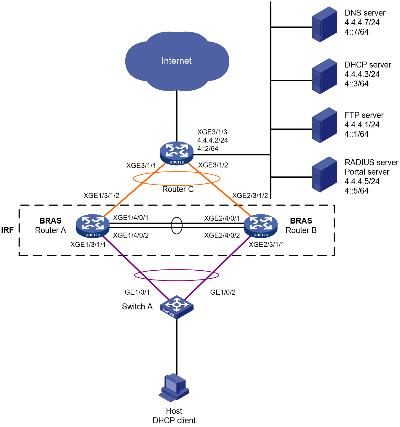
Table 15 IP address planning table
|
Device |
Interface |
IP address |
Device |
Interface |
IP address |
|
DNS server |
N/A |
4.4.4.7/24 4::7/64 |
IRF fabric (BRAS) |
RAGG1 |
N/A |
|
DHCP server |
N/A |
4.4.4.3/24 4::3/64 |
|
RAGG1023 |
100.1.1.1/24 100::1/64 |
|
FTP server |
N/A |
4.4.4.1/24 4::1/64 |
|
XGE1/3/1/1 |
N/A |
|
RADIUS server and portal server |
|
4.4.4.5/24 4::5/64 |
|
XGE2/3/1/1 |
N/A |
|
Router C |
RAGG1023 |
100.1.1.2/24 100::2/64 |
|
XGE1/3/1/2 |
N/A |
|
|
XGE3/1/1 |
N/A |
|
XGE2/3/1/2 |
N/A |
|
|
XGE3/1/2 |
N/A |
|
LoopBack1 |
80.1.1.1/32 80::1/128 |
|
|
XGE3/1/3 |
4.4.4.2/24 4::2/64 |
|
|
|
Analysis
· To prevent single points of failure from affecting normal service traffic forwarding, configure multichassis link aggregation on the IRF fabric for service traffic forwarding.
· To minimize the impacts of IRF split on services, configure LACP MAD on the IRF fabric. You only need to configure LACP MAD on one aggregate interface. LACP MAD requires an IRF-capable intermediate device running software that can recognize and process LACPDUs containing the ActiveID field. In this example, Switch A is used as the intermediate device for LACP MAD.
· To guarantee bandwidth for users, authorize CAR actions to users for rate limiting.
· For the inbound traffic in the IPoE Web preauthentication domain, configure the following traffic classes and behaviors:
¡ Configure a traffic class to match traffic destined for the DNS server in a user group that accommodates users in the preauthentication domain, and configure the filter permit traffic behavior accordingly. The user group that accommodates users in the preauthentication domain is referred to as the preauthentication user group for simplicity in this example.
¡ Configure a traffic class to match traffic destined for the portal server in the preauthentication user group, and configure the filter permit traffic behavior accordingly.
¡ Configure a traffic class to match traffic destined for the internal network server in the preauthentication user group, and configure the filter permit traffic behavior accordingly.
¡ Configure a traffic class to match HTTP traffic in the preauthentication user group, and configure the redirect http-to-cpu traffic behavior accordingly.
¡ Configure a traffic class to match HTTPS traffic in the preauthentication user group, and configure the redirect https-to-cpu traffic behavior accordingly.
¡ Configure a traffic class to match IP traffic in the preauthentication user group, and configure the redirect cpu traffic behavior accordingly. (The configuration is required only for transparent authentication.)
¡ Configure a traffic class to match IP traffic in the preauthentication user group, and configure the filter deny traffic behavior accordingly.
· For the outbound traffic in the IPoE Web preauthentication domain, configure the following traffic classes and behaviors:
¡ Configure a traffic class to match traffic from the DNS server in the preauthentication user group, and configure the filter permit traffic behavior accordingly.
¡ Configure a traffic class to match traffic from the portal server in the preauthentication user group, and configure the filter permit traffic behavior accordingly.
¡ Configure a traffic class to match traffic from the internal network server in the preauthentication user group, and configure the filter permit traffic behavior accordingly.
¡ Configure a traffic class to match IP traffic in the preauthentication user group, and configure the filter deny traffic behavior accordingly.
· To ensure that an unauthenticated or defaulting user can still access the internal websites of the campus and actively pay the charge, you can configure the object group-based URL allowlist and add the internal websites of the campus (FTP server, and AAA and portal server in this example) and the payment page address (https://www.alipay.com/xxx in this example) to the URL allowlist.
· To facilitate QoS policy-based control for users, assign users to different user groups based on their states:
¡ Preauthentication users: In this phase, users have not passed IPoE Web authentication and need access control. Assign these users to the user group named pre.
¡ Defaulting users: Defaulting users need access control. Assign these users to the user group named qianfei.
¡ Normal users: These users do not need access control. Assign these users to the user group named web.
· For users in user group pre and user group qianfei, perform the following QoS policy-based controls separately:
¡ Users in user group pre
- Can access the addresses on the URL allowlist.
- When a user accesses an address not on the URL allowlist through HTTP or HTTPS, all requests are redirected to the Web authentication page (http://www.ipv4web.com or http://www.ipv6.web.com in this example), and the other traffic is dropped.
¡ Users in user group qianfei
- Can access the addresses on the URL allowlist.
- When a user accesses an address not on the URL allowlist through HTTP or HTTPS, all requests are redirected to the payment page (https://www.alipay.com/xxx in this example), and the other traffic is dropped.
Restrictions and guidelines
In this example, the DHCP server is simulated by a device. As a best practice, use a dedicated DHCP server in practical applications.
To prevent port conflicts from causing service unavailability, make sure the listening port numbers are not well-known port numbers or port numbers used by other TCP-based services. To view the TCP port numbers already used by services, use the display tcp command.
In this example, DHCPv4 assigns IPv4 addresses to endpoints, and DHCPv6 assigns IPv6 addresses to endpoints. Once an endpoint passes authentication in one stack, it can access the network resources in both stacks. However, the configuration in this example might cause an Android phone failing to obtain an IPv6 address.
Procedure
Configuring IP addresses and routes
# On Router C, assign an IPv4 address and an IPv6 address to Ten-GigabitEthernet 3/1/3 (the interface connected to the servers).
<RouterC> system-view
[RouterC] interface ten-gigabitethernet 3/1/3
[RouterC-Ten-GigabitEthernet3/1/3] ip address 4.4.4.2 24
[RouterC-Ten-GigabitEthernet3/1/3] ipv6 address 4::2 64
[RouterC-Ten-GigabitEthernet3/1/3] quit
# On Router C, configure static routes destined for users.
[RouterC] ip route-static 192.168.0.0 24 100.1.1.1
[RouterC] ipv6 route-static 192:: 64 100::1
Configuring the DNS server
Configure the DNS server correctly so that the server can resolve the IPv4 or IPv6 URL address corresponding to the Web authentication page at http://www.ipv4.web.com or http://www.ipv6.web.com based on the first protocol stack type used by a dual-stack IPoE user when the user comes online.
In this example, Windows Server 2016 is used to describe the basic DNS server configuration.
To configure the DNS server:
1. Install the DNS component:
a. Log in to the server, click Start, and then select Server Manager.
b. Click Add roles and features.
c. In the Before You Begin step, click Next.
d. In the Installation Type step, use the default setting, which is role-based or feature-based installation, and then click Next.
e. In the Server Selection step, use the default setting, which is Select a server from the server pool, and then click Next.
f. In the Server Roles step, select DNS Server. In the wizard window that opens, click Add Features, and then click Next.
g. In the Features step, use the default settings, and then click Next.
h. In the DNS Server step, click Next.
i. In the Confirmation step, click Install and wait for the installation to complete.
j. In the Results step, click Close.
2. Create an IPv4 forward lookup zone:
a. In the Server Manager window, click Tools, and then select DNS.
b. In the DNS Manager window, right click Forward Lookup Zones, and then select New Zone.
c. In the New Zone Wizard window, click Next.
d. In the Zone Type step, select Primary zone, and then click Next.
e. In the Zone Name step, enter zone name ipv4.web.com.
f. In the Zone File step, use the default settings, and then click Next.
g. In the Dynamic Update step, select Do not allow dynamic updates, and then click Next.
h. Click Finish.
i. In the DNS Manager window, click Forward Lookup Zones, right click ipv4.web.com, and then select New Host.
j. In the New Host window, enter host name www and IP address 4.4.4.7, and then click Add Host.
3. Create an IPv4 reverse lookup zone:
a. In the DNS Manager window, right click Reverse Lookup Zones, and then select New Zone.
b. In the New Zone Wizard window, click Next.
c. In the Zone Type step, select Primary zone, and then click Next.
d. In the Reverse Lookup Zone Name step, select IPv4 Reverse Lookup Zone, and then click Next.
e. Enter network ID 4.4.4, and then click Next.
f. In the Zone File step, use the default settings, and then click Next.
g. In the Dynamic Update step, select Do not allow dynamic updates, and then click Next.
h. Click Finish.
i. In the DNS Manager window, click Reverse Lookup Zones, right click 4.4.4.in-addr.arpa.dns, and then select New Pointer.
j. In the New Resource Record window, enter host IP address 4.4.4.7 and host name www.ipv4.web.com, and then click OK.
4. Create an IPv6 forward lookup zone:
a. In the Server Manager window, click Tools, and then select DNS.
b. In the DNS Manager window, right click Forward Lookup Zones, and then select New Zone.
c. In the New Zone Wizard window, click Next.
d. In the Zone Type step, select Primary zone, and then click Next.
e. In the Zone Name step, enter zone name ipv6.web.com.
f. In the Zone File step, use the default settings, and then click Next.
g. In the Dynamic Update step, select Do not allow dynamic updates, and then click Next.
h. Click Finish.
i. In the DNS Manager window, click Forward Lookup Zones, right click ipv6.web.com, and then select New Host.
j. In the New Host window, enter host name www and IP address 4::7, and then click Add Host.
5. Create an IPv6 reverse lookup zone:
a. In the DNS Manager window, right click Reverse Lookup Zones, and then select New Zone.
b. In the New Zone Wizard window, click Next.
c. In the Zone Type step, select Primary zone, and then click Next.
d. In the Reverse Lookup Zone Name step, select IPv6 Reverse Lookup Zone, and then click Next.
e. Enter network ID 4000:0000:0000:0000::/64, and then click Next.
f. In the Zone File step, use the default settings, and then click Next.
g. In the Dynamic Update step, select Do not allow dynamic updates, and then click Next.
h. Click Finish.
i. In the DNS Manager window, click Reverse Lookup Zones, right click 0.0.0.0.0.0.0.0.0.0.0.0.0.0.0.4.in-addr.arpa.dns, and then select New Pointer.
j. In the New Resource Record window, enter host IP address 4000.0000.0000.0000.0000.0000.0000.0007 and host name www.ipv6.web.com, and then click OK.
Configuring the AAA server
You must use this feature together with AAA. Before configuring this feature, make sure the AAA server supports H3C private attributes 246 (H3C-Auth-Detail-Result) and 250 (H3C-WEB-URL) and can assign these attributes to defaulting users. This example does not cover detailed AAA server configuration.
· Attribute 246 (H3C-Auth-Detail-Result) indicates the user authentication result details. Possible values for the attribute include:
¡ 0—Normal user. In this case, the server will cancel assigning attribute 250 and allow the user to access any network resources.
¡ 1—Defaulting user. In this case, the server will assign attribute 250 and allow the user to access network resources on the URL allowlist. If the user accesses other network resources, the requests will be redirected to the URL defined in attribute 250.
¡ 2—User whose broadband usage has expired. In this case, the server will assign attribute 250. The first Web access request of the user will be redirected to the URL defined in attribute 250.
· Attribute 250 (H3C-WEB-URL) is used to carry the Web redirection URL for users, and is used together with attribute 246.
Configuring the DHCP server
1. Configure a DHCPv4 address pool:
# Enable DHCP.
<DHCP> system-view
[DHCP] dhcp enable
# Enable the DHCP server to return a DHCP-NAK message if the client notions of their IP addresses are incorrect.
[DHCP] dhcp server request-ip-address check
# Create a DHCPv4 address pool named pool1 and enter its view.
[DHCP] ip pool pool1
# Specify primary subnet 192.168.0.0/24 for dynamic allocation and DNS server 4.4.4.7 in address pool pool1.
[DHCP-ip-pool-pool1] network 192.168.0.0 24
[DHCP-ip-pool-pool1] dns-list 4.4.4.7
# Specify gateway address 192.168.0.1 in address pool pool1.
[DHCP-ip-pool-pool1] gateway-list 192.168.0.1
# Exclude IP address 192.168.0.1 from dynamic allocation in address pool pool1.
[DHCP-ip-pool-pool1] forbidden-ip 192.168.0.1
[DHCP-ip-pool-pool1] quit
# Configure a static route. You can configure routing according to the actual network situation.
[DHCP] ip route-static 0.0.0.0 0 4.4.4.2
2. Configure a DHCPv6 address pool:
# Create a DHCPv6 address pool named pool2 and enter its view.
[DHCP] ipv6 pool pool2
# Specify primary subnet 192::/64 for dynamic allocation and DNS server 4::7 in address pool pool2.
[DHCP-ipv6-pool-pool2] network 192::/64
[DHCP-ipv6-pool-pool2] dns-server 4::7
[DHCP-ipv6-pool-pool2] quit
# Exclude IP address 192::1 from dynamic allocation in address pool pool2.
[DHCP] ipv6 dhcp server forbidden-address 192::1
# Enable the DHCPv6 server on Ten-GigabitEthernet 3/1/1.
[DHCP] interface ten-gigabitethernet 3/1/1
[DHCP-Ten-GigabitEthernet3/1/1] ipv6 dhcp select server
[DHCP-Ten-GigabitEthernet3/1/1] quit
# Configure a static route. You can configure routing according to the actual network situation.
[DHCP] ipv6 route-static :: 0 4::2
Configuring the RADIUS server and portal server
In this example, Srun 4.0.9 is installed on the server.
To configure the RADIUS server and portal server:
1. Enter http://4.4.4.5:8081 in the address bar of a Web browser, log in to the server, and add an access device:
# Open the page for managing devices, click the tab for adding devices, and add a device.
¡ Set the device name to BRAS.
¡ Use the IP address of Loopback 1 on the BRAS device as the NAS IP address. In this example, the IP address is 80.1.1.1.
¡ Use IP address 4.4.4.5 as ours IP address.
¡ Select NAS types Huawei, H3C, and Srun gateway.
¡ Set the DM port to 3799.
¡ Set the RADIUS key to 123456.
¡ Select to not discard traffic.
¡ Select H3C and Huawei (h3c v1.2) as the portal protocols.
¡ Set the portal key to 123456.
# Configure RADIUS trust settings:
a. Enter the RADIUS page, and click the link for accessing the RADIUS trust settings page.
b. On the page, continuously click Generate in the upper right corner until the generation succeeds.
c. Restart the Srun RADIUS process.
# Click the tab for configuring RADIUS service settings, and configure the system to validate usernames with the domain name.
2. Enter https://4.4.4.5:8080 in the address bar of a Web browser, log in to the server, and add a user:
a. Click the tab for managing and adding users, and then add a user.
b. Set the account name to user1 and the password to pass.
3. To deploy other settings such as control policies and product policies, see the manuals for the Srun server.
Setting up an IRF fabric
1. Use Router A and Router B to set up an IRF fabric:
# Assign member ID 1 to Router A, and bind Ten-GigabitEthernet 4/0/1 and Ten-GigabitEthernet 4/0/2 to IRF-port 2.
<RouterA> system-view
[RouterA] irf member 1 priority 2
[RouterA] interface ten-gigabitethernet 4/0/1
[RouterA-Ten-GigabitEthernet4/0/1] port link-mode bridge
[RouterA-Ten-GigabitEthernet4/0/1] quit
[RouterA] interface ten-gigabitethernet 4/0/2
[RouterA-Ten-GigabitEthernet4/0/2] port link-mode bridge
[RouterA-Ten-GigabitEthernet4/0/2] quit
[RouterA] irf-port 2
[RouterA-irf-port2] port group interface ten-gigabitethernet 4/0/1
[RouterA-irf-port2] port group interface ten-gigabitethernet 4/0/2
[RouterA-irf-port2] quit
# Save the running configuration to the main next-startup configuration file.
[RouterA] quit
<RouterA> save
# Enable IRF mode.
<RouterA> system-view
[RouterA] chassis convert mode irf
The device will switch to IRF mode and reboot. Continue?[Y/N]:y
You are recommended to save the current running configuration and specify the configuration file for the next startup. Now save the running configuration to the next-startup configuration file? [Y/N]:y
Please input the file name(*.cfg)[cfa0:/test.cfg]
(To leave the existing filename unchanged, press the enter key):
cfa0:/test.cfg exists, overwrite? [Y/N]:y
Validating file. Please wait...
Saved the current configuration to mainboard device successfully.
Do you want to convert the content of the next startup configuration file cfa0:/test.cfg to make it available in IRF mode? [Y/N]:y
Now rebooting, please wait...
A single-member IRF fabric that contains only Router A is set up after the router reboots.
# Assign member ID 2 to Router B, and bind Ten-GigabitEthernet 4/0/1 and Ten-GigabitEthernet 4/0/2 to IRF-port 1.
<RouterB> system-view
[RouterB] irf member 2 priority 1
[RouterB] interface ten-gigabitethernet 4/0/1
[RouterB-Ten-GigabitEthernet4/0/1] port link-mode bridge
[RouterB-Ten-GigabitEthernet4/0/1] quit
[RouterB] interface ten-gigabitethernet 4/0/2
[RouterB-Ten-GigabitEthernet4/0/2] port link-mode bridge
[RouterB-Ten-GigabitEthernet4/0/2] quit
[RouterB] irf-port 1
[RouterB-irf-port1] port group interface ten-gigabitethernet 4/0/1
[RouterB-irf-port1] port group interface ten-gigabitethernet 4/0/2
[RouterB-irf-port1] quit
# Save the running configuration to the main next-startup configuration file.
[RouterB] quit
<RouterB> save
# Enable IRF mode.
<RouterB> system-view
[RouterB] chassis convert mode irf
The device will switch to IRF mode and reboot. Continue?[Y/N]:y
You are recommended to save the current running configuration and specify the configuration file for the next startup. Now save the running configuration to the next-startup configuration file? [Y/N]:y
Please input the file name(*.cfg)[cfa0:/test.cfg]
(To leave the existing filename unchanged, press the enter key):
cfa0:/test.cfg exists, overwrite? [Y/N]:y
Validating file. Please wait...
Saved the current configuration to mainboard device successfully.
Do you want to convert the content of the next startup configuration file cfa0:/test.cfg to make it available in IRF mode? [Y/N]:y
Now rebooting, please wait...
Router B joins the IRF fabric that contains Router A after it reboots.
2. Configure downlink services for the IRF fabric:
a. Configure LACP MAD:
In this example, Router A acts as the master device in the IRF fabric and acts as a BRAS device in IPoE. For ease of understanding, Router A will be referred to as IRF in the subsequent IRF configuration steps and as BRAS in the subsequent IPoE configuration steps.
After the IRF fabric is established, you can configure settings for service modules. Once the IRF fabric is established, you can log in to the IRF fabric from any member device for configuration. By default, the device name of the IRF fabric is the name of the master device. In this example, the master device is Router A.
# Create Route-Aggregation 1 (the Layer 3 aggregate interface connected to Switch A), configure the aggregation group to operate in dynamic aggregation mode, and enable LACP MAD on the aggregate interface.
<IRF> system-view
[IRF] interface route-aggregation 1
[IRF-Route-Aggregation1] link-aggregation mode dynamic
[IRF-Route-Aggregation1] mad enable
You need to assign a domain ID (range: 0-4294967295)
[Current domain is: 0]:
The assigned domain ID is: 0
MAD LACP only enable on dynamic aggregation interface.
[IRF-Route-Aggregation1] quit
# Assign interfaces connected to Switch A to Layer 3 aggregation group 1.
[IRF] interface ten-gigabitethernet 1/3/1/1
[IRF-Ten-GigabitEthernet1/3/1/1] port link-aggregation group 1
[IRF-Ten-GigabitEthernet1/3/1/1] quit
[IRF] interface ten-gigabitethernet 2/3/1/1
[IRF-Ten-GigabitEthernet2/3/1/1] port link-aggregation group 1
[IRF-Ten-GigabitEthernet2/3/1/1] quit
b. Configure Switch A:
# Create Bridge-Aggregation 1 (the Layer 2 aggregate interface connected to the IRF fabric), and configure the aggregation group to operate in dynamic aggregation mode. The aggregate interface will be used for IRF LACP MAD.
<SwitchA> system-view
[SwitchA] interface bridge-aggregation 1
[SwitchA-Bridge-Aggregation1] link-aggregation mode dynamic
[SwitchA-Bridge-Aggregation1] quit
# Assign interfaces connected to the IRF fabric to Layer 2 aggregation group 1.
[SwitchA] interface gigabitethernet 1/0/1
[SwitchA-GigabitEthernet1/0/1] port link-aggregation group 1
[SwitchA-GigabitEthernet1/0/1] quit
[SwitchA] interface gigabitethernet 1/0/2
[SwitchA-GigabitEthernet1/0/2] port link-aggregation group 1
[SwitchA-GigabitEthernet1/0/2] quit
3. Configure uplink services for the IRF fabric:
a. Configure aggregation group settings on the IRF fabric:
# Create Route-Aggregation 1023 (the Layer 3 aggregate interface connected to Router C), configure the aggregation group to operate in dynamic aggregation mode, and assign an IPv4 address and an IPv6 address to the aggregate interface.
[IRF] interface route-aggregation 1023
[IRF-Route-Aggregation1023] link-aggregation mode dynamic
[IRF-Route-Aggregation1023] ip address 100.1.1.1 24
[IRF-Route-Aggregation1023] ipv6 address 100::1 64
[IRF-Route-Aggregation1023] quit
# Assign interfaces connected to Router C to Layer 3 aggregation group 1023.
[IRF] interface ten-gigabitethernet 1/3/1/2
[IRF-Ten-GigabitEthernet1/3/1/2] port link-aggregation group 1023
[IRF-Ten-GigabitEthernet1/3/1/2] quit
[IRF] interface ten-gigabitethernet 2/3/1/2
[IRF-Ten-GigabitEthernet2/3/1/2] port link-aggregation group 1023
[IRF-Ten-GigabitEthernet2/3/1/2] quit
# Configure static routes destined for Router C (for accessing servers and the Internet).
[IRF] ip route-static 0.0.0.0 0 100.1.1.2
[IRF] ipv6 route-static :: 0 100::2
b. Configure Router C:
In this example, the configuration steps only cover the IRF-side settings. The routing protocol used for the external network is not described.
# Create Route-Aggregation 1023 (the Layer 3 aggregate interface connected to the IRF fabric), configure the aggregation group to operate in dynamic aggregation mode, and assign an IPv4 address and an IPv6 address to the aggregate interface.
<RouterC> system-view
[RouterC] interface route-aggregation 1023
[RouterC-Route-Aggregation1023] link-aggregation mode dynamic
[RouterC-Route-Aggregation1023] ip address 100.1.1.2 24
[RouterC-Route-Aggregation1023] ipv6 address 100::2 64
[RouterC-Route-Aggregation1023] quit
# Assign interfaces connected to the IRF fabric to Layer 3 aggregation group 1023.
[RouterC] interface ten-gigabitethernet 3/1/1
[RouterC-Ten-GigabitEthernet3/1/1] port link-aggregation group 1023
[RouterC-Ten-GigabitEthernet3/1/1] quit
[RouterC] interface ten-gigabitethernet 3/1/2
[RouterC-Ten-GigabitEthernet3/1/2] port link-aggregation group 1023
[RouterC-Ten-GigabitEthernet3/1/2] quit
Configuring BRAS settings
1. Configure the DHCP relay agent:
# Enable DHCP globally.
[BRAS] dhcp enable
# Create a remote BAS IP pool named pool1, specify the gateway IP address of the subnet where the DHCPv4 clients reside, and specify the DHCP server at 4.4.4.3 for the remote BAS IP pool.
[BRAS] ip pool pool1 bas remote
[BRAS-ip-pool-pool1] gateway 192.168.0.1 24
[BRAS-ip-pool-pool1] remote-server 4.4.4.3
[BRAS-ip-pool-pool1] quit
# Create an IPv6 address pool named pool2, specify the subnet where the DHCPv6 clients reside, and specify the DHCP server at 4::3 for the IPv6 address pool.
[BRAS] ipv6 pool pool2
[BRAS-ipv6-pool-pool2] gateway-list 192::1
[BRAS-ipv6-pool-pool2] network 192::/64 export-route
[BRAS-ipv6-pool-pool2] remote-server 4::3
[BRAS-ipv6-pool-pool2] quit
# Enable the DHCPv4 relay agent on Route-Aggregation 1.
[BRAS] interface route-aggregation 1
[BRAS–Route-Aggregation1] dhcp select relay
# Configure Route-Aggregation 1 to automatically generate a link-local address. The link-local address will be used as the gateway IP address of users.
[BRAS–Route-Aggregation1] ipv6 address auto link-local
# Enable the DHCPv6 relay agent on Route-Aggregation 1.
[BRAS–Route-Aggregation1] ipv6 dhcp select relay
# Disable RA message suppression on Route-Aggregation 1. Set the managed address configuration flag (M) to 1 in RA advertisements to be sent. Then, the host uses a DHCPv6 server to obtain IPv6 addresses. Set the other stateful configuration flag (O) to 1 in RA advertisements to be sent. Then, the host uses a DHCPv6 server to obtain configuration information other than IPv6 addresses.
[BRAS–Route-Aggregation1] undo ipv6 nd ra halt
[BRAS–Route-Aggregation1] ipv6 nd autoconfig managed-address-flag
[BRAS–Route-Aggregation1] ipv6 nd autoconfig other-flag
[BRAS–Route-Aggregation1] quit
2. Configure the portal authentication server:
# Create an IPv4 portal authentication server named newpt1, configure its IP address as 4.4.4.5, and set its key to 123456 in plaintext form.
[BRAS] portal server newpt1
[BRAS-portal-server-newpt1] ip 4.4.4.5 key simple 123456
[BRAS-portal-server-newpt1] quit
# Create an IPv6 portal authentication server named newpt2, configure its IPv6 address as 4::5, and set its key to 123456 in plaintext form.
[BRAS] portal server newpt2
[BRAS-portal-server-newpt2] ipv6 4::5 key simple 123456
[BRAS-portal-server-newpt2] quit
3. Configure the HTTPS redirect listening port number:
# Specify 11111 as the HTTPS redirect listening port number. Make sure the port number is not used by any other service. To see the TCP port numbers used by other services, execute the display tcp command.
[BRAS] http-redirect https-port 11111
4. Configure the BRAS to get user access information from ARP and ND entries.
[BRAS] portal access-info trust arp
[BRAS] portal access-info trust nd
5. Create local user groups:
# Create a user group named pre for preauthentication.
[BRAS] user-group pre
New user group added.
[BRAS-ugroup-pre] quit
# Create a user group named qianfei for defaulting users.
[BRAS] user-group qianfei
New user group added.
[BRAS-ugroup-qianfei] quit
# Create a user group named web.
[BRAS] user-group web
New user group added.
[BRAS-ugroup-web] quit
6. Configure QoS settings:
a. Configure URL allowlists:
# Create an IP address object group (URL allowlist) named freeurl_ipv4, and add the internal websites of the campus and the payment page to the URL allowlist.
[BRAS] object-group ip address freeurl_ipv4
[BRAS-obj-grp-ip-freeurl_ipv4] network host address 4.4.4.1 //FTP server address
[BRAS-obj-grp-ip-freeurl_ipv4] network host address 4.4.4.5 //Portal server address
[BRAS-obj-grp-ip-freeurl_ipv4] network host address 4.4.4.7 //DNS server address
[BRAS-obj-grp-ip-freeurl-ipv4] network host name https://www.alipay.com/xxx //Payment page address
[BRAS-obj-grp-ip-freeurlipv4] quit
# Create an IPv6 address object group (URL allowlist) named freeurl_ipv6, and add the internal websites of the campus and the payment page to the URL allowlist.
[BRAS] object-group ipv6 address freeurl_ipv6
[BRAS-obj-grp-ipv6-freeurl_ipv6] network host address 4::1 //FTP server address
[BRAS-obj-grp-ipv6-freeurl_ipv6] network host address 4::5 //Portal server address
[BRAS-obj-grp-ipv6-freeurl_ipv6] network host address 4::7 //DNS server address
[BRAS-obj-grp-ipv6-freeurl_ipv6] network host name https://www.alipay.com/xxx //Payment page address
[BRAS-obj-grp-ipv6-freeurl_ipv6] quit
b. Configure common ACLs for URL allowlists, which apply to both preauthentication users and defaulting users:
# Create rules for IPv4 and IPv6 advanced ACLs freeurl_permit_in separately to allow packets from users in user group pre and user group qianfei to the addresses on the allowlist.
[BRAS] acl advanced name freeurl_permit_in
[BRAS-acl-ipv4-adv-freeurl_permit_in] rule 10 permit ip destination object-group freeurl_ipv4 user-group pre
[BRAS-acl-ipv4-adv-freeurl_permit_in] rule 20 permit ip destination object-group freeurl_ipv4 user-group qianfei
[BRAS-acl-ipv4-adv-freeurl_permit_in] quit
[BRAS] acl ipv6 advanced name freeurl_permit_in
[BRAS-acl-ipv6-adv-freeurl_permit_in] rule 10 permit ipv6 destination object-group freeurl_ipv6 user-group pre
[BRAS-acl-ipv6-adv-freeurl_permit_in] rule 20 permit ipv6 destination object-group freeurl_ipv6 user-group qianfei
[BRAS-acl-ipv6-adv-freeurl_permit_in] quit
# Create rules for IPv4 and IPv6 advanced ACLs freeurl_permit_out separately to match packets that users in user group pre and user group qianfei receive from the addresses on the allowlist.
[BRAS] acl advanced name freeurl_permit_out
[BRAS-acl-ipv4-adv-freeurl_permit_out] rule 10 permit ip source object-group freeurl_ipv4 user-group pre
[BRAS-acl-ipv4-adv-freeurl_permit_out] rule 20 permit ip source object-group freeurl_ipv4 user-group qianfei
[BRAS-acl-ipv4-adv-freeurl_permit_out] quit
[BRAS] acl ipv6 advanced name freeurl_permit_out
[BRAS-acl-ipv6-adv-freeurl_permit_out] rule 10 permit ipv6 source object-group freeurl_ipv6 user-group pre
[BRAS-acl-ipv6-adv-freeurl_permit_out] rule 20 permit ipv6 source object-group freeurl_ipv6 user-group qianfei
[BRAS-acl-ipv6-adv-freeurl_permit_out] quit
c. Configure ACLs for preauthentication:
# Create an IPv4 and IPv6 advanced ACL named web_http separately. Configure a rule to permit TCP packets with the destination port 80 (HTTP packets) from users in user group pre.
[BRAS] acl advanced name web_http
[BRAS-acl-ipv4-adv-web_http] rule 0 permit tcp destination-port eq www user-group pre
[BRAS-acl-ipv4-adv-web_http] quit
[BRAS] acl ipv6 advanced name web_http
[BRAS-acl-ipv6-adv-web_http] rule 0 permit tcp destination-port eq www user-group pre
[BRAS-acl-ipv6-adv-web_http] quit
# Create an IPv4 and IPv6 advanced ACL named web_https separately, and configure a rule to permit TCP packets with the destination port 443 (HTTPS packets) from users in user group pre.
[BRAS] acl advanced name web_https
[BRAS-acl-ipv4-adv-web_https] rule 0 permit tcp destination-port eq 443 user-group pre
[BRAS-acl-ipv4-adv-web_https] quit
[BRAS] acl ipv6 advanced name web_https
[BRAS-acl-ipv6-adv-web_https] rule 0 permit tcp destination-port eq 443 user-group pre
[BRAS-acl-ipv6-adv-web_https] quit
# Create an IPv4 and IPv6 advanced ACL named ip separately, and configure a rule to permit IP packets from users in user group pre.
[BRAS] acl advanced name ip
[BRAS-acl-ipv4-adv-ip] rule 0 permit ip user-group pre
[BRAS-acl-ipv4-adv-ip] quit
[BRAS] acl ipv6 advanced name ip
[BRAS-acl-ipv6-adv-ip] rule 0 permit ipv6 user-group pre
[BRAS-acl-ipv6-adv-ip] quit
d. Configure the ACLs for defaulting users:
# Create rules for IPv4 and IPv6 advanced ACLs qianfei_web_http separately to match TCP packets that users in user group qianfei use to access port 80, that is, HTTP packets.
[BRAS] acl advanced name qianfei_web_http
[BRAS-acl-ipv4-adv-qianfei_web_http] rule 0 permit tcp destination-port eq www user-group qianfei
[BRAS-acl-ipv4-adv-qianfei_web_http] quit
[BRAS] acl ipv6 advanced name qianfei_web_http
[BRAS-acl-ipv6-adv-qianfei_web_http] rule 0 permit tcp destination-port eq www user-group qianfei
[BRAS-acl-ipv6-adv-qianfei_web_http] quit
# Create rules for IPv4 and IPv6 advanced ACLs qianfei_web_https separately to match TCP packets that users in user group qianfei use to access port 443, that is, HTTPS packets.
[BRAS] acl advanced name qianfei_web_https
[BRAS-acl-ipv4-adv-qianfei_web_https] rule 0 permit tcp destination-port eq 443 user-group qianfei
[BRAS-acl-ipv4-adv-qianfei_web_https] quit
[BRAS] acl ipv6 advanced name qianfei_web_https
[BRAS-acl-ipv6-adv-qianfei_web_https] rule 0 permit tcp destination-port eq 443 user-group qianfei
[BRAS-acl-ipv6-adv-qianfei_web_https] quit
# Create rules for IPv4 and IPv6 advanced ACLs qianfei_ip separately to match IP packets of users in user group qianfei.
[BRAS] acl advanced name qianfei_ip
[BRAS-acl-ipv4-adv-qianfei_ip] rule 0 permit ip user-group qianfei
[BRAS-acl-ipv4-adv-qianfei_ip] quit
[BRAS] acl ipv6 advanced name qianfei_ip
[BRAS-acl-ipv6-adv-qianfei_ip] rule 0 permit ipv6 user-group qianfei
[BRAS-acl-ipv6-adv-qianfei_ip] quit
e. Configure common traffic classes for URL allowlists, which apply to both preauthentication users and defaulting users:
# Create a traffic class named freeurl_permit_in, and use ACL freeurl_permit_in as the match criterion.
[BRAS] traffic classifier freeurl_permit_in operator or
[BRAS-classifier-freeurl_permit_in] if-match acl name freeurl_permit_in
[BRAS-classifier-freeurl_permit_in] if-match acl ipv6 name freeurl_permit_in
[BRAS-classifier-freeurl_permit_in] quit
# Create a traffic class named freeurl_permit_out, and use ACL freeurl_permit_out as the match criterion.
[BRAS] traffic classifier freeurl_permit_out operator or
[BRAS-classifier-freeurl_permit_out] if-match acl name freeurl_permit_out
[BRAS-classifier-freeurl_permit_out] if-match acl ipv6 name freeurl_permit_out
[BRAS-classifier-freeurl_permit_out] quit
f. Configure QoS traffic classes for preauthentication users:
# Create traffic class web_http and specify ACL web_http as the match criterion.
[BRAS] traffic classifier web_http operator or
[BRAS-classifier-web_http] if-match acl name web_http
[BRAS-classifier-web_http] if-match acl ipv6 name web_http
[BRAS-classifier-web_http] quit
# Create traffic class web_https and specify ACL web_https as the match criterion.
[BRAS] traffic classifier web_https operator or
[BRAS-classifier-web_https] if-match acl name web_https
[BRAS-classifier-web_https] if-match acl ipv6 name web_https
[BRAS-classifier-web_https] quit
# Create traffic class web_deny and specify ACL ip as the match criterion.
[BRAS] traffic classifier web_deny operator or
[BRAS-classifier-web_deny] if-match acl name ip
[BRAS-classifier-web_deny] if-match acl ipv6 name ip
[BRAS-classifier-web_deny] quit
g. Configure the traffic classes for defaulting users:
# Create a traffic class named qianfei_web_http and use ACL qianfei_web_http as the match criterion.
[BRAS] traffic classifier qianfei_web_http operator or
[BRAS-classifier-qianfei_web_http] if-match acl name qianfei_web_http
[BRAS-classifier-qianfei_web_http] if-match acl ipv6 name qianfei_web_http
[BRAS-classifier-qianfei_web_http] quit
# Create a traffic class named qianfei_web_https, and use ACL qianfei_web_https as the match criterion.
[BRAS] traffic classifier qianfei_web_https operator or
[BRAS-classifier-qianfei_web_https] if-match acl name qianfei_web_https
[BRAS-classifier-qianfei_web_https] if-match acl ipv6 name qianfei_web_https
[BRAS-classifier-qianfei_web_https] quit
# Create a traffic class named qianfei_web_deny, and use ACL qianfei_ip as the match criterion.
[BRAS] traffic classifier qianfei_web_deny operator or
[BRAS-classifier-qianfei_web_deny] if-match acl name qianfei_ip
[BRAS-classifier-qianfei_web_deny] if-match acl ipv6 name qianfei_ip
[BRAS-classifier-qianfei_web_deny] quit
h. Configure common traffic behaviors for URL allowlists, which apply to both preauthentication users and defaulting users:
# Create a traffic behavior named freeurl_permit_in, and allow users in user group pre and user group qianfei to access the addresses on the allowlist.
[BRAS] traffic behavior freeurl_permit_in
[BRAS-behavior-freeurl_permit_in] filter permit
[BRAS-behavior-freeurl_permit_in] free account
[BRAS-behavior-freeurl_permit_in] quit
# Create a traffic behavior named freeurl_permit_out, and allow packets from the addresses on the allowlist to users in user group pre and user group qianfei.
[BRAS] traffic behavior freeurl_permit_out
[BRAS-behavior-freeurl_permit_out] filter permit
[BRAS-behavior-freeurl_permit_out] free account
[BRAS-behavior-freeurl_permit_out] quit
i. Configure QoS traffic behaviors for preauthentication users:
# Configure traffic behavior web_http to redirect HTTP packets to the CPU.
[BRAS] traffic behavior web_http
[BRAS-behavior-web_http] redirect http-to-cpu
[BRAS-behavior-web_http] quit
# Configure traffic behavior web_https to redirect HTTPS packets to the CPU.
[BRAS] traffic behavior web_https
[BRAS-behavior-web_https] redirect https-to-cpu
[BRAS-behavior-web_https] quit
# Configure traffic behavior web_deny to deny traffic.
[BRAS] traffic behavior web_deny
[BRAS-behavior-web_deny] filter deny
[BRAS-behavior-web_deny] free account
[BRAS-behavior-web_deny] quit
j. Configure traffic behaviors for defaulting users:
# Create a traffic behavior named qianfei_web_http, and redirect TCP packets that users in user group qianfei use to access port 80 (HTTP packets) to the CPU.
[BRAS] traffic behavior qianfei_web_http
[BRAS-behavior-qianfei_web_http] redirect http-to-cpu
[BRAS-behavior-qianfei_web_http] quit
# Create a traffic behavior named qianfei_web_https, and redirect TCP packets that users in user group qianfei use to access port 443 (HTTPS packets) to the CPU.
[BRAS] traffic behavior qianfei_web_https
[BRAS-behavior-qianfei_web_https] redirect https-to-cpu
[BRAS-behavior-qianfei_web_https] quit
# Create a traffic behavior named qianfei_web_deny, and deny all IP packets from the users in user group qianfei.
[BRAS] traffic behavior qianfei_web_deny
[BRAS-behavior-qianfei_web_deny] filter deny
[BRAS-behavior-qianfei_web_deny] free account
[BRAS-behavior-qianfei_web_deny] quit
k. Configure QoS policies:
# Create a QoS policy named web.
[BRAS] qos policy web
# Permit the traffic from users in user group pre and user group qianfei to the addresses on the allowlist to pass through. Then, when a student does not pass IPoE Web authentication or has passed IPoE Web authentication but has owed fees, the student is still allowed to access the internal websites of the campus and access the payment page to pay the charge. In this way, the student can still learn and communicate normally.
[BRAS-qospolicy-web] classifier freeurl_permit_in behavior freeurl_permit_in
# Redirect the HTTP packets from users in user group pre to the Web authentication page.
[BRAS-qospolicy-web] classifier web_http behavior web_http
# Redirect the HTTPS packets from users in user group pre to the Web authentication page.
[BRAS-qospolicy-web] classifier web_https behavior web_https
# Redirect the HTTP packets from users in user group qianfei to the payment page.
[BRAS-qospolicy-web] classifier qianfei_web_http behavior qianfei_web_http
# Redirect the HTTPS packets from users in user group qianfei to the payment page.
[BRAS-qospolicy-web] classifier qianfei_web_https behavior qianfei_web_https
# Drop all the other traffic from users in user group pre.
[BRAS-qospolicy-web] classifier web_deny behavior web_deny
# Drop all the other traffic from users in user group qianfei.
[BRAS-qospolicy-web] classifier qianfei_web_deny behavior qianfei_web_deny
[BRAS-qospolicy-web] quit
# Create a QoS policy named out.
[BRAS] qos policy out
# Allow packets from the addresses on the allowlist to users in user group pre and user group qianfei to pass through.
[BRAS-qospolicy-out] classifier freeurl_permit_out behavior freeurl_permit_out
# Drop all the other traffic from users in user group pre.
[BRAS-qospolicy-out] classifier web_deny behavior web_deny
# Drop all the other traffic from users in user group qianfei.
[BRAS-qospolicy-out] classifier qianfei_web_deny behavior qianfei_web_deny
[BRAS-qospolicy-out] quit
l. Apply the QoS policies:
# Apply QoS policy web to the inbound traffic globally. To identify whether the QoS policy takes effect, execute the display qos policy global inbound command.
[BRAS] qos apply policy web global inbound
# Apply QoS policy out to the outbound traffic globally. To identify whether the QoS policy takes effect, execute the display qos policy global outbound command.
[BRAS] qos apply policy out global outbound
7. Configure a RADIUS scheme:
# Create a RADIUS scheme named rs1 and enter its view.
[BRAS] radius scheme rs1
# Configure primary servers and keys for authentication and accounting.
[BRAS-radius-rs1] primary authentication 4.4.4.5
[BRAS-radius-rs1] primary accounting 4.4.4.5
[BRAS-radius-rs1] key authentication simple 123456
[BRAS-radius-rs1] key accounting simple 123456
# Exclude the ISP domain name from the usernames sent to the RADIUS servers.
[BRAS-radius-rs1] user-name-format without-domain
# Set the IPv4 NAS-IP address carried in RADIUS packets to 80.1.1.1.
[BRAS-radius-rs1] nas-ip 80.1.1.1
[BRAS-radius-rs1] quit
# Specify the RADIUS DAE client at 4.4.4.5, and set the shared key to 123456 in plaintext form for secure communication between the DAE server and client. Make sure the shared key is the same as the key configured on the RADIUS DAE client.
[BRAS] radius dynamic-author server
[BRAS-radius-da-server] client ip 4.4.4.5 key simple 123456
[BRAS-radius-da-server] quit
8. Configure the preauthentication ISP domain and Web authentication ISP domain:
# Configure ISP domain dm1 for IPoE user preauthentication.
[BRAS] domain name dm1
[BRAS-isp-dm1] authentication ipoe none
[BRAS-isp-dm1] authorization ipoe none
[BRAS-isp-dm1] accounting ipoe none
# Configure the authorization user group and IPv4 and IPv6 address pools in preauthentication ISP domain dm1.
[BRAS-isp-dm1] authorization-attribute user-group pre
[BRAS-isp-dm1] authorization-attribute ip-pool pool1
[BRAS-isp-dm1] authorization-attribute ipv6-pool pool2
# Configure the Web authentication page URLs in ISP domain dm1.
[BRAS-isp-dm1] web-server url http://www.ipv4.web.com
[BRAS-isp-dm1] web-server ipv6-url http://www.ipv6.web.com
[BRAS-isp-dm1] quit
# Configure ISP domain dm2 for IPoE user Web authentication, and specify a CAR policy and a user group in the ISP domain.
[BRAS] domain name dm2
[BRAS-isp-dm2] authentication ipoe radius-scheme rs1
[BRAS-isp-dm2] authorization ipoe radius-scheme rs1
[BRAS-isp-dm2] accounting ipoe radius-scheme rs1
[BRAS-isp-dm2] authorization-attribute car inbound cir 5120 outbound cir 5120
[BRAS-isp-dm2] authorization-attribute user-group web
[BRAS-isp-dm2] quit
9. Configure IPoE:
# Enable IPoE and configure the Layer 2 access mode for users on Route-Aggregation 1.
[BRAS] interface route-aggregation 1
[BRAS–Route-Aggregation1] ip subscriber l2-connected enable
# Configure the Web authentication method for IPoE users on Route-Aggregation 1.
[BRAS–Route-Aggregation1] ip subscriber authentication-method web
The operation may cut all users on this interface. Continue?[Y/N]:y
# Specify ISP domain dm1 as the Web preauthentication domain and ISP domain dm2 as the Web authentication domain on Route-Aggregation 1.
[BRAS–Route-Aggregation1] ip subscriber pre-auth domain dm1
[BRAS–Route-Aggregation1] ip subscriber web-auth domain dm2
[BRAS–Route-Aggregation1] quit
10. Configure attack defense:
¡ Configure source MAC-based ARP attack detection:
# Enable source MAC-based ARP attack detection and specify the filter handling method.
[BRAS] arp source-mac filter
Set the check interval for source MAC-based ARP attack detection to 5 seconds.
[BRAS] arp source-mac check-interval 5
# Set the threshold for source MAC-based ARP attack detection to 30.
[BRAS] arp source-mac threshold 30
# Set the aging time for ARP attack entries to 300 seconds.
[BRAS] arp source-mac aging-time 300
¡ Configure source MAC-based ND attack detection:
# Enable source MAC-based ND attack detection and specify the filter handling method.
[BRAS] ipv6 nd source-mac filter
# Set the check interval for source MAC-based ND attack detection to 5 seconds.
[BRAS] ipv6 nd source-mac check-interval 5
# Set the threshold for source MAC-based ND attack detection to 30.
[BRAS] ipv6 nd source-mac threshold 30
# Set the aging time for ND attack entries to 300 seconds.
[BRAS] ipv6 nd source-mac aging-time 300
¡ Configure DHCP flood attack protection:
# Enable DHCP flood attack protection on Route-Aggregation 1.
[BRAS] interface route-aggregation 1
[BRAS-Route-Aggregation1] dhcp flood-protection enable
[BRAS–Route-Aggregation1] quit
# Configure the device to allow a maximum of 30 DHCP packets per 10000 milliseconds from each DHCP client.
[BRAS] dhcp flood-protection threshold 30 10000
# Set the DHCP flood attack entry aging time to 300 seconds.
[BRAS] dhcp flood-protection aging-time 300
¡ Configure DHCPv6 flood attack protection:
# Enable DHCPv6 flood attack protection on Route-Aggregation 1.
[BRAS] interface route-aggregation 1
[BRAS-Route-Aggregation1] ipv6 dhcp flood-protection enable
[BRAS-Route-Aggregation1] quit
# Configure the device to allow a maximum of 30 DHCPv6 packets per 10000 milliseconds from each DHCPv6 client.
[BRAS] ipv6 dhcp flood-protection threshold 30 10000
# Set the DHCPv6 flood attack entry aging time to 300 seconds.
[BRAS] ipv6 dhcp flood-protection aging-time 300
¡ Enable ICMP/ICMPv6 fast reply.
[BRAS] ip icmp fast-reply enable
[BRAS] ipv6 icmpv6 fast-reply enable
¡ Configure TCP SYN flood attack prevention:
# Enable flow-based TCP SYN flood attack prevention.
[BRAS] tcp anti-syn-flood flow-based enable
# Set the check interval to 20 seconds for flow-based TCP SYN flood attack prevention.
[BRAS] tcp anti-syn-flood flow-based check-interval 20
# Set the threshold to 2000 for triggering flow-based TCP SYN flood attack prevention.
[BRAS] tcp anti-syn-flood flow-based threshold 2000
# Set the flow-based TCP SYN flood attack prevention duration to 5 minutes.
[BRAS] tcp anti-syn-flood flow-based duration 5
¡ Configure HTTP/HTTPS attack defense:
# Enable destination IP-based IPoE HTTP/HTTPS attack defense.
[BRAS] ip subscriber http-defense destination-ip enable
# Trigger attack defense when the total number of HTTP/HTTPS packets sent to the same destination IP address within 300 seconds reaches 6000.
[BRAS] ip subscriber http-defense destination-ip threshold 6000 interval 300
¡ Enable HTTP packet fast reply:
# Enable HTTP packet fast reply on Route-Aggregation 1.
[BRAS] interface route-aggregation 1
[BRAS-Route-Aggregation1] ip subscriber http-fast-reply enable
[BRAS-Route-Aggregation1] quit
Verifying the configuration
# After the user passes authentication in the preauthentication domain, display information about online IPoE users to verify that the user has come online and obtained IPv4 address 192.168.0.2 and IPv6 address 192::2.
[BRAS] display access-user interface route-aggregation 1
UserID Interface IP address MAC address S-/C-VLAN
Username Access type
IPv6 address
0x5c RAGG1 192.168.0.2 000c-29a6-b656 -/-
000c29a6b656 L2 IPoE dynamic
192::2
# On the Web authentication page, enter the username and password, and then bring the user online. After the user passes Web authentication, display information about online IPoE users.
[BRAS] display access-user interface route-aggregation 1
UserID Interface IP address MAC address S-/C-VLAN
Username Access type
IPv6 address
0x5c RAGG1 192.168.0.2 000c-29a6-b656 -/-
user1 Web auth
192::2
# When a user owes fee, the AAA server assigns the following attributes to the user:
user-name =user1 , H3C-User-Group = qianfei,h3c-web-url = "www.alipay.com/xxx",H3C-Auth_Detail_Result = 1
Where, each attribute is explained as follows:
· user-name =user1 //The username of the defaulting user is user1.
· H3C-User-Group = qianfei //The user group named qianfei is assigned to the defaulting user.
· H3C-Auth-Detail-Result=1 //The value 1 means the user is a defaulting user and can access only addresses on the URL allowlist. When the user accesses an address not on the URL allowlist through HTTP or HTTPS, the packets are redirected to the website specified in the H3C-WEB-URL attribute.
· H3c-WEB-URL="https://www.alipay.com/xxx" //This attribute specifies the website to which packets from the defaulting user are redirected.
In this case, the user can access only addresses on the URL allowlist through HTTP. When the user accesses an address not on the URL allowlist through HTTP, the packets are redirected to the website https://www.alipay.com/xxx. For example, when you enter http://www.163.com/ in the address bar of a browser, you are redirected to the payment page.
# After the user pays the charge, the AAA server assigns the following attributes to the user:
user-name =user1 , H3C-User-Group =web ,H3C-Auth_Detail_Result = 0
Where, each attribute is explained as follows:
· user-name =user1 //The username of the user who has paid the charge is user1.
· H3C-User-Group = web //The user group named web is assigned to the user who has paid the charge, and the user is removed user group qianfei.
· H3C-Auth-Detail-Result=0 //The value 0 means the redirection action is canceled for the user.
In this case, the user can access any network resources. For example, when you enter http://www.baidu.com/ in the address bar of a browser, the Baidu page opens normally.
Configuration files
· DHCP server:
#
dhcp enable
dhcp server request-ip-address check
#
ipv6 dhcp server forbidden-address 192::1
#
ip pool pool1
gateway-list 192.168.0.1
network 192.168.0.0 mask 255.255.255.0
dns-list 4.4.4.7
forbidden-ip 192.168.0.1
#
ipv6 pool pool2
network 192::/64
dns-server 4::7
#
interface Ten-GigabitEthernet3/1/1
ip address 4.4.4.3 255.255.255.0
ipv6 dhcp select server
ipv6 address 4::3/64
#
ip route-static 0.0.0.0 0 4.4.4.2
ipv6 route-static :: 0 4::2
#
· Router C:
#
interface Route-Aggregation1023
ip address 100.1.1.2 255.255.255.0
ipv6 address 100::2/64
link-aggregation mode dynamic
#
interface Ten-GigabitEthernet3/1/1
port link-aggregation group 1023
#
interface Ten-GigabitEthernet3/1/2
port link-aggregation group 1023
#
interface Ten-GigabitEthernet3/1/3
ip address 4.4.4.2 255.255.255.0
ipv6 address 4::2/64
#
ip route-static 192.168.0.0 24 100.1.1.1
ipv6 route-static 192:: 64 100::1
#
· IRF fabric (BRAS):
#
irf mac-address persistent always
irf auto-update enable
irf auto-merge enable
undo irf link-delay
irf member 1 priority 2
irf member 2 priority 1
#
irf-port 1/2
port group interface Ten-GigabitEthernet1/4/0/1 mode enhanced
port group interface Ten-GigabitEthernet1/4/0/2 mode enhanced
#
irf-port 2/1
port group interface Ten-GigabitEthernet2/4/0/1 mode enhanced
port group interface Ten-GigabitEthernet2/4/0/2 mode enhanced
#
dhcp enable
#
object-group ip address freeurl_ipv4
0 network host address 4.4.4.1
10 network host address 4.4.4.5
20 network host address 4.4.4.7
30 network host name https://www.alipay.com/xxx
#
object-group ipv6 address freeurl_ipv6
0 network host address 4::1
10 network host address 4::5
20 network host address 4::7
30 network host name https://www.alipay.com/xxx
#
traffic classifier freeurl_permit_in operator or
if-match acl name freeurl_permit_in
if-match acl ipv6 name freeurl_permit_in
#
traffic classifier freeurl_permit_out operator or
if-match acl name freeurl_permit_out
if-match acl ipv6 name freeurl_permit_out
#
traffic classifier qianfei_web_deny operator or
if-match acl name qianfei_ip
if-match acl ipv6 name qianfei_ip
#
traffic classifier qianfei_web_http operator or
if-match acl name qianfei_web_http
if-match acl ipv6 name qianfei_web_http
#
traffic classifier qianfei_web_https operator or
if-match acl name qianfei_web_https
if-match acl ipv6 name qianfei_web_https
#
traffic classifier web_deny operator or
if-match acl name ip
if-match acl ipv6 name ip
#
traffic classifier web_http operator or
if-match acl name web_http
if-match acl ipv6 name web_http
#
traffic classifier web_https operator or
if-match acl name web_https
if-match acl ipv6 name web_https
#
traffic behavior freeurl_permit_in
filter permit
free account
#
traffic behavior freeurl_permit_out
filter permit
free account
#
traffic behavior qianfei_web_deny
filter deny
free account
#
traffic behavior qianfei_web_http
redirect http-to-cpu
#
traffic behavior qianfei_web_https
redirect https-to-cpu
#
traffic behavior web_deny
filter deny
free account
#
traffic behavior web_http
redirect http-to-cpu
#
traffic behavior web_https
redirect https-to-cpu
#
qos policy out
classifier freeurl_permit_out behavior freeurl_permit_out
classifier web_deny behavior web_deny
classifier qianfei_web_deny behavior qianfei_web_deny
#
qos policy web
classifier freeurl_permit_in behavior freeurl_permit_in
classifier web_http behavior web_http
classifier web_https behavior web_https
classifier qianfei_web_http behavior qianfei_web_http
classifier qianfei_web_https behavior qianfei_web_https
classifier web_deny behavior web_deny
classifier qianfei_web_deny behavior qianfei_web_deny
#
interface Route-Aggregation1
link-aggregation mode dynamic
mad enable
dhcp select relay
dhcp flood-protection enable
ipv6 dhcp select relay
ipv6 dhcp flood-protection enable
ipv6 address auto link-local
ipv6 nd autoconfig managed-address-flag
ipv6 nd autoconfig other-flag
undo ipv6 nd ra halt
ip subscriber l2-connected enable
ip subscriber http-fast-reply enable
ip subscriber authentication-method web
ip subscriber pre-auth domain dm1
ip subscriber web-auth domain dm2
#
interface Route-Aggregation1023
ip address 100.1.1.1 255.255.255.0
ipv6 address 100::1/64
link-aggregation mode dynamic
#
interface Ten-GigabitEthernet1/3/1/1
port link-aggregation group 1
#
interface Ten-GigabitEthernet2/3/1/1
port link-aggregation group 1
#
interface Ten-GigabitEthernet1/3/1/2
port link-aggregation group 1023
#
interface Ten-GigabitEthernet2/3/1/2
port link-aggregation group 1023
#
qos apply policy web global inbound
qos apply policy out global outbound
#
ip pool pool1 bas remote
gateway 192.168.0.1 mask 255.255.255.0
remote-server 4.4.4.3
#
ipv6 pool pool2
network 192::/64 export-route
gateway-list 192::1
remote-server 4::3
#
ip route-static 0.0.0.0 0 100.1.1.2
ipv6 route-static :: 0 100::2
#
acl advanced name freeurl_permit_in
rule 10 permit ip destination object-group freeurl_ipv4 user-group pre
rule 20 permit ip destination object-group freeurl_ipv4 user-group qianfei
#
acl advanced name freeurl_permit_out
rule 10 permit ip source object-group freeurl_ipv4 user-group pre
rule 20 permit ip source object-group freeurl_ipv4 user-group qianfei
#
acl advanced name ip
rule 0 permit ip user-group pre
#
acl advanced name qianfei_ip
rule 0 permit ip user-group qianfei
#
acl advanced name qianfei_web_http
rule 0 permit tcp destination-port eq www user-group qianfei
#
acl advanced name qianfei_web_https
rule 0 permit tcp destination-port eq 443 user-group qianfei
#
acl advanced name web_http
rule 0 permit tcp destination-port eq www user-group pre
#
acl advanced name web_https
rule 0 permit tcp destination-port eq 443 user-group pre
#
acl ipv6 advanced name freeurl_permit_in
rule 10 permit ipv6 destination object-group freeurl_ipv6 user-group pre
rule 20 permit ipv6 destination object-group freeurl_ipv6 user-group qianfei
#
acl ipv6 advanced name freeurl_permit_out
rule 10 permit ipv6 source object-group freeurl_ipv6 user-group pre
rule 20 permit ipv6 source object-group freeurl_ipv6 user-group qianfei
#
acl ipv6 advanced name ip
rule 0 permit ipv6 user-group pre
#
acl ipv6 advanced name qianfei_ip
rule 0 permit ipv6 user-group qianfei
#
acl ipv6 advanced name qianfei_web_http
rule 0 permit tcp destination-port eq www user-group qianfei
#
acl ipv6 advanced name qianfei_web_https
rule 0 permit tcp destination-port eq 443 user-group qianfei
#
acl ipv6 advanced name web_http
rule 0 permit tcp destination-port eq www user-group pre
#
acl ipv6 advanced name web_https
rule 0 permit tcp destination-port eq 443 user-group pre
#
radius scheme rs1
primary authentication 4.4.4.5
primary accounting 4.4.4.5
key authentication cipher $c$3$FhQVcgn3kq1exL0CdTzatcgc9xF9vL3ZOw==
key accounting cipher $c$3$ntIHBRM4ZkG+2JRZQTdKmNl0kYJmhZz5Zg==
user-name-format without-domain
nas-ip 80.1.1.1
#
radius dynamic-author server
client ip 4.4.4.5 key cipher $c$3$lYC2ERe8ts2gtE6M2xfoDDB8NmGw6J9v/Q==
#
domain name dm1
authorization-attribute user-group pre
authorization-attribute ip-pool pool1
authorization-attribute ipv6-pool pool2
authentication ipoe none
authorization ipoe none
accounting ipoe none
web-server url http://www.ipv4.web.com
web-server ipv6-url http://www.ipv6.web.com
#
domain name dm2
authorization-attribute user-group web
authorization-attribute car inbound cir 5120 outbound cir 5120
authentication ipoe radius-scheme rs1
authorization ipoe radius-scheme rs1
accounting ipoe radius-scheme rs1
#
user-group pre
#
user-group qianfei
#
user-group web
#
portal server newpt1
ip 4.4.4.5 key cipher $c$3$UnoFeLybwld9jDwLnHJQptDE7YZry2EVlw==
#
portal server newpt2
ipv6 4::5 key cipher $c$3$HxisNWeML9fhYRS+7umwGbYwAkL+KGiCjw==
#
portal access-info trust arp
portal access-info trust nd
#
http-redirect https-port 11111
#
tcp anti-syn-flood flow-based enable
tcp anti-syn-flood flow-based threshold 2000
tcp anti-syn-flood flow-based check-interval 20
#
ip icmp fast-reply enable
#
dhcp flood-protection threshold 30 10000
#
ipv6 dhcp flood-protection threshold 30 10000
#
ipv6 icmpv6 fast-reply enable
#
ip subscriber http-defense destination-ip enable
#
ipv6 nd source-mac filter
#
arp source-mac filter
#
Layer 2 common Web authentication + 802.1x authentication configuration example for dual-stack IPoE users (DHCP relay + authorization address pool)
Traditional wired 802.1X is a Layer 2 port-based network access control protocol that is usually deployed on access or aggregation switches. IPoE and other traditional BRAS access methods are Layer 3 interface-based network access control protocols that are typically deployed on BRAS devices. In hybrid networks where there both 802.1X authentication and traditional BRAS authentication are required, deploying 802.1X directly on the BRAS device and supporting coexistence with other BRAS access methods such as IPoE on a single interface offers the following benefits:
· Administrators can flexibly choose one or more access methods to deploy on BRAS devices according to their business needs.
· It facilitates simultaneous management of 802.1X users and BRAS users on the BRAS device, simplifying network management and reducing operational costs.
This example introduces the application of BRAS-level 802.1X authentication and IPoE coexistence scenarios.
Network configuration
As shown in Figure 45, Router A and Router B are two BRAS devices in a school. They form an IRF fabric to provide IPoE access services for school users. Configure the entities in the network to meet the following requirements:
· The host is connected to the BRAS device through a Layer 2 network using IPoE. The host can choose to go online using either 802.1X authentication or IPoE Web authentication as needed.
· The BRAS acts a DHCP relay agent to request IP addresses from the remote DHCP server.
· A server installed with Srun software acts as the RADIUS server, portal authentication server, and portal Web server.
· The FTP server is an internal network server.
· After a user passes IPoE Web authentication, its speed is limited to 5 Mbps.
· On the BRAS device, configure basic attack defense settings for protocol packets, such as ARP and DHCP packets, to prevent illegal packets from impacting the network.
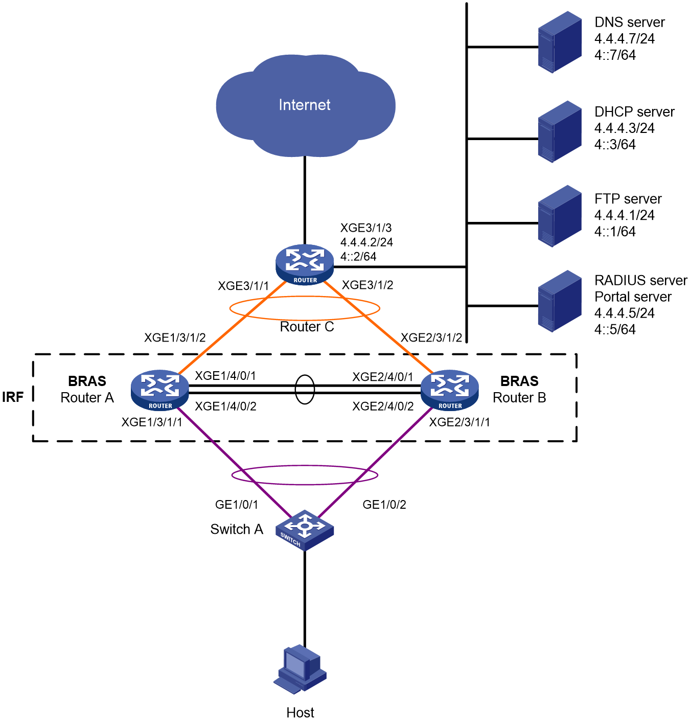
Table 16 IP address planning table
|
Device |
Interface |
IP address |
Device |
Interface |
IP address |
|
DNS server |
N/A |
4.4.4.7/24 4::7/64 |
IRF fabric (BRAS) |
RAGG1 |
N/A |
|
DHCP server |
N/A |
4.4.4.3/24 4::3/64 |
|
RAGG1023 |
100.1.1.1/24 100::1/64 |
|
FTP server |
N/A |
4.4.4.1/24 4::1/64 |
|
XGE1/3/1/1 |
N/A |
|
RADIUS server and portal server |
|
4.4.4.5/24 4::5/64 |
|
XGE2/3/1/1 |
N/A |
|
Router C |
RAGG1023 |
100.1.1.2/24 100::2/64 |
|
XGE1/3/1/2 |
N/A |
|
|
XGE3/1/1 |
N/A |
|
XGE2/3/1/2 |
N/A |
|
|
XGE3/1/2 |
N/A |
|
LoopBack1 |
80.1.1.1/32 80::1/128 |
|
|
XGE3/1/3 |
4.4.4.2/24 4::2/64 |
|
|
|
Analysis
· To prevent single points of failure from affecting normal service traffic forwarding, configure multichassis link aggregation on the IRF fabric for service traffic forwarding.
· To minimize the impacts of IRF split on services, configure LACP MAD on the IRF fabric. You only need to configure LACP MAD on one aggregate interface. LACP MAD requires an IRF-capable intermediate device running software that can recognize and process LACPDUs containing the ActiveID field. In this example, Switch A is used as the intermediate device for LACP MAD.
· To guarantee bandwidth for users, authorize CAR actions to users for rate limiting.
· For the inbound traffic in the IPoE Web preauthentication domain, configure the following traffic classes and behaviors:
¡ Configure a traffic class to match traffic destined for the DNS server in a user group that accommodates users in the preauthentication domain, and configure the filter permit traffic behavior accordingly. The user group that accommodates users in the preauthentication domain is referred to as the preauthentication user group for simplicity in this example.
¡ Configure a traffic class to match traffic from the portal server in the preauthentication user group, and configure the filter permit traffic behavior accordingly.
¡ Configure a traffic class to match traffic from the internal network server in the preauthentication user group, and configure the filter permit traffic behavior accordingly.
¡ Configure a traffic class to match HTTP traffic in the preauthentication user group, and configure the redirect http-to-cpu traffic behavior accordingly.
¡ Configure a traffic class to match HTTPS traffic in the preauthentication user group, and configure the redirect https-to-cpu traffic behavior accordingly.
¡ Configure a traffic class to match IP traffic in the preauthentication user group, and configure the redirect cpu traffic behavior accordingly. (The configuration is required only for transparent authentication.)
¡ Configure a traffic class to match IP traffic in the preauthentication user group, and configure the filter deny traffic behavior accordingly.
· For the outbound traffic in the IPoE Web preauthentication domain, configure the following traffic classes and behaviors:
¡ Configure a traffic class to match traffic from the DNS server in the preauthentication user group, and configure the filter permit traffic behavior accordingly.
¡ Configure a traffic class to match traffic from the portal server in the preauthentication user group, and configure the filter permit traffic behavior accordingly.
¡ Configure a traffic class to match traffic from the internal network server in the preauthentication user group, and configure the filter permit traffic behavior accordingly.
¡ Configure a traffic class to match IP traffic in the preauthentication user group, and configure the filter deny traffic behavior accordingly.
Restrictions and guidelines
The DHCP server in this example is simulated by a device. As a best practice, use a dedicated DHCP server in actual applications.
To prevent port conflicts from causing service unavailability, make sure the listening port numbers are not well-known port numbers or port numbers used by other TCP-based services. To view the TCP port numbers already used by services, use the display tcp command.
In this example, DHCPv4 assigns IPv4 addresses to endpoints, and DHCPv6 assigns IPv6 addresses to endpoints. Once an endpoint passes authentication in one stack, it can access the networks in both stacks. However, the configuration in this example might cause an Android phone failing to obtain an IPv6 address.
Procedures
Configuring IP addresses and routes
# On Router C, assign an IPv4 address and an IPv6 address to Ten-GigabitEthernet 3/1/3 (the interface connected to the servers).
<RouterC> system-view
[RouterC] interface ten-gigabitethernet 3/1/3
[RouterC-Ten-GigabitEthernet3/1/3] ip address 4.4.4.2 24
[RouterC-Ten-GigabitEthernet3/1/3] ipv6 address 4::2 64
[RouterC-Ten-GigabitEthernet3/1/3] quit
# On Router C, configure static routes destined for users.
[RouterC] ip route-static 192.168.0.0 24 100.1.1.1
[RouterC] ipv6 route-static 192:: 64 100::1
Configuring the DNS server
Configure the DNS server correctly so that the server can resolve the IPv4 or IPv6 URL address corresponding to the Web authentication page (in this example, http://www.ipv4.web.com and http://www.ipv6.web.com) based on the first protocol stack type used by a dual-stack IPoE user when the user comes online.
In this example, Windows Server 2016 is used to describe the basic DNS server configuration.
To configure the DNS server:
1. Install the DNS component:
a. Log in to the server, click Start, and then select Server Manager.
b. Click Add roles and features.
c. In the Before You Begin step, click Next.
d. In the Installation Type step, use the default setting, which is role-based or feature-based installation, and then click Next.
e. In the Server Selection step, use the default setting, which is Select a server from the server pool, and then click Next.
f. In the Server Roles step, select DNS Server. In the wizard window that opens, click Add Features, and then click Next.
g. In the Features step, use the default settings, and then click Next.
h. In the DNS Server step, click Next.
i. In the Confirmation step, click Install and wait for the installation to complete.
j. In the Results step, click Close.
2. Create an IPv4 forward lookup zone:
a. In the Server Manager window, click Tools, and then select DNS.
b. In the DNS Manager window, right click Forward Lookup Zones, and then select New Zone.
c. In the New Zone Wizard window, click Next.
d. In the Zone Type step, select Primary zone, and then click Next.
e. In the Zone Name step, enter zone name ipv4.web.com.
f. In the Zone File step, use the default settings, and then click Next.
g. In the Dynamic Update step, select Do not allow dynamic updates, and then click Next.
h. Click Finish.
i. In the DNS Manager window, click Forward Lookup Zones, right click ipv4.web.com, and then select New Host.
j. In the New Host window, enter host name www and IP address 4.4.4.7, and then click Add Host.
3. Create an IPv4 reverse lookup zone:
a. In the DNS Manager window, right click Reverse Lookup Zones, and then select New Zone.
b. In the New Zone Wizard window, click Next.
c. In the Zone Type step, select Primary zone, and then click Next.
d. In the Reverse Lookup Zone Name step, select IPv4 Reverse Lookup Zone, and then click Next.
e. Enter network ID 4.4.4, and then click Next.
f. In the Zone File step, use the default settings, and then click Next.
g. In the Dynamic Update step, select Do not allow dynamic updates, and then click Next.
h. Click Finish.
i. In the DNS Manager window, click Reverse Lookup Zones, right click 4.4.4.in-addr.arpa.dns, and then select New Pointer.
j. In the New Resource Record window, enter host IP address 4.4.4.7 and host name www.ipv4.web.com, and then click OK.
4. Create an IPv6 forward lookup zone:
a. In the Server Manager window, click Tools, and then select DNS.
b. In the DNS Manager window, right click Forward Lookup Zones, and then select New Zone.
c. In the New Zone Wizard window, click Next.
d. In the Zone Type step, select Primary zone, and then click Next.
e. In the Zone Name step, enter zone name ipv6.web.com.
f. In the Zone File step, use the default settings, and then click Next.
g. In the Dynamic Update step, select Do not allow dynamic updates, and then click Next.
h. Click Finish.
i. In the DNS Manager window, click Forward Lookup Zones, right click ipv6.web.com, and then select New Host.
j. In the New Host window, enter host name www and IP address 4::7, and then click Add Host.
5. Create an IPv6 reverse lookup zone:
a. In the DNS Manager window, right click Reverse Lookup Zones, and then select New Zone.
b. In the New Zone Wizard window, click Next.
c. In the Zone Type step, select Primary zone, and then click Next.
d. In the Reverse Lookup Zone Name step, select IPv6 Reverse Lookup Zone, and then click Next.
e. Enter network ID 4000:0000:0000:0000::/64, and then click Next.
f. In the Zone File step, use the default settings, and then click Next.
g. In the Dynamic Update step, select Do not allow dynamic updates, and then click Next.
h. Click Finish.
i. In the DNS Manager window, click Reverse Lookup Zones, right click 0.0.0.0.0.0.0.0.0.0.0.0.0.0.0.4.in-addr.arpa.dns, and then select New Pointer.
j. In the New Resource Record window, enter host IP address 4000.0000.0000.0000.0000.0000.0000.0007 and host name www.ipv6.web.com, and then click OK.
Configure the DHCP server:
1. Configure an IPv4 address pool:
# Enable DHCP.
<DHCP> system-view
[DHCP] dhcp enable
# Enable the DHCP server to return a DHCP-NAK message if the client notions of their IP addresses are incorrect.
[DHCP] dhcp server request-ip-address check
# Create an IPv4 address pool named pool1 and enter its view.
[DHCP] ip pool pool1
# Specify primary subnet 192.168.0.0/24 for dynamic allocation and DNS server 4.4.4.7 in address pool pool1.
[DHCP-ip-pool-pool1] network 192.168.0.0 24
[DHCP-ip-pool-pool1] dns-list 4.4.4.7
# Specify gateway address 192.168.0.1 in address pool pool1.
[DHCP-ip-pool-pool1] gateway-list 192.168.0.1
# Exclude IP address 192.168.0.1 from dynamic allocation in address pool pool1.
[DHCP-ip-pool-pool1] forbidden-ip 192.168.0.1
[DHCP-ip-pool-pool1] quit
Configure the default route. (This example uses the default route. In the live network, configure the route according to actual needs.)
[DHCP] ip route-static 0.0.0.0 0 4.4.4.2
2. Configure an IPv6 address pool:
# Create an IPv6 address pool named pool2 and enter its view.
[DHCP] ipv6 pool pool2
# Specify primary subnet 192::/64 for dynamic allocation and DNS server 4::7 in address pool pool2.
[DHCP-ipv6-pool-pool2] network 192::/64
[DHCP-ipv6-pool-pool2] dns-server 4::7
[DHCP-ipv6-pool-pool2] quit
# Exclude IP address 192::1 from dynamic allocation in address pool pool2.
[DHCP] ipv6 dhcp server forbidden-address 192::1
# Enable the DHCPv6 server on interface Ten-GigabitEthernet 3/1/1.
[DHCP] interface ten-gigabitethernet 3/1/1
[DHCP-Ten-GigabitEthernet3/1/1] ipv6 dhcp select server
[DHCP-Ten-GigabitEthernet3/1/1] quit
Configure the default route. (This example uses the default route. In the live network, configure the route according to actual needs.)
[DHCP] ipv6 route-static :: 0 4::2
Configuring the RADIUS server and portal server
In this example, Srun 4.0.9 is installed on the server.
1. Enter http://4.4.4.5:8081 in the address bar of a Web browser, log in to the server, and add an access device:
# Open the page for managing devices, click the tab for adding devices, and add a device.
¡ Set the device name to BRAS.
¡ Use the IP address of Loopback 1 on the BRAS device as the NAS IP address. In this example, the IP address is 80.1.1.1.
¡ Use IP address 4.4.4.5 as ours IP address.
¡ Select NAS types Huawei, H3C, and Srun gateway.
¡ Set the DM port to 3799.
¡ Set the RADIUS key to 123456.
¡ Select to not discard traffic.
¡ Select H3C and Huawei (h3c v1.2) as the portal protocols.
¡ Set the portal key to 123456.
# Configure RADIUS trust settings:
a. Enter the RADIUS page, and click the link for accessing the RADIUS trust settings page.
b. On the page, continuously click Generate in the upper right corner until the generation succeeds.
c. Restart the Srun RADIUS process.
# Click the tab for configuring RADIUS service settings, and configure the system to validate usernames with the domain name.
2. Enter https://4.4.4.5:8080 in the address bar of a Web browser, log in to the server, and add a user:
Click the tab for managing and adding users, and then add a user.
¡ Set the account name to user1 and the password to pass.
3. To deploy other settings such as control policies and product policies, see the manuals for the Srun server.
Setting up an IRF fabric
1. Use Router A and Router B to set up an IRF fabric:
# Assign member ID 1 to Router A, and bind Ten-GigabitEthernet 4/0/1 and Ten-GigabitEthernet 4/0/2 to IRF-port 2.
<RouterA> system-view
[RouterA] irf member 1 priority 2
[RouterA] interface ten-gigabitethernet 4/0/1
[RouterA-Ten-GigabitEthernet4/0/1] port link-mode bridge
[RouterA-Ten-GigabitEthernet4/0/1] quit
[RouterA] interface ten-gigabitethernet 4/0/2
[RouterA-Ten-GigabitEthernet4/0/2] port link-mode bridge
[RouterA-Ten-GigabitEthernet4/0/2] quit
[RouterA] irf-port 2
[RouterA-irf-port2] port group interface ten-gigabitethernet 4/0/1
[RouterA-irf-port2] port group interface ten-gigabitethernet 4/0/2
[RouterA-irf-port2] quit
# Save the running configuration to the main next-startup configuration file.
[RouterA] quit
<RouterA> save
# Enable IRF mode.
<RouterA> system-view
[RouterA] chassis convert mode irf
The device will switch to IRF mode and reboot. Continue?[Y/N]:y
You are recommended to save the current running configuration and specify the configuration file for the next startup. Now save the running configuration to the next-startup configuration file? [Y/N]:y
Please input the file name(*.cfg)[cfa0:/test.cfg]
(To leave the existing filename unchanged, press the enter key):
cfa0:/test.cfg exists, overwrite? [Y/N]:y
Validating file. Please wait...
Saved the current configuration to mainboard device successfully.
Do you want to convert the content of the next startup configuration file cfa0:/test.cfg to make it available in IRF mode? [Y/N]:y
Now rebooting, please wait...
A single-member IRF fabric that contains only Router A is set up after the router reboots.
# Assign member ID 2 to Router B, and bind Ten-GigabitEthernet 4/0/1 and Ten-GigabitEthernet 4/0/2 to IRF-port 1.
<RouterB> system-view
[RouterB] irf member 2 priority 1
[RouterB] interface ten-gigabitethernet 4/0/1
[RouterB-Ten-GigabitEthernet4/0/1] port link-mode bridge
[RouterB-Ten-GigabitEthernet4/0/1] quit
[RouterB] interface ten-gigabitethernet 4/0/2
[RouterB-Ten-GigabitEthernet4/0/2] port link-mode bridge
[RouterB-Ten-GigabitEthernet4/0/2] quit
[RouterB] irf-port 1
[RouterB-irf-port1] port group interface ten-gigabitethernet 4/0/1
[RouterB-irf-port1] port group interface ten-gigabitethernet 4/0/2
[RouterB-irf-port1] quit
# Save the running configuration to the main next-startup configuration file.
[RouterB] quit
<RouterB> save
# Enable IRF mode.
<RouterB> system-view
[RouterB] chassis convert mode irf
The device will switch to IRF mode and reboot. Continue?[Y/N]:y
You are recommended to save the current running configuration and specify the configuration file for the next startup. Now save the running configuration to the next-startup configuration file? [Y/N]:y
Please input the file name(*.cfg)[cfa0:/test.cfg]
(To leave the existing filename unchanged, press the enter key):
cfa0:/test.cfg exists, overwrite? [Y/N]:y
Validating file. Please wait...
Saved the current configuration to mainboard device successfully.
Do you want to convert the content of the next startup configuration file cfa0:/test.cfg to make it available in IRF mode? [Y/N]:y
Now rebooting, please wait...
Router B joins the IRF fabric that contains Router A after it reboots.
2. Configure downlink services for the IRF fabric:
a. Configure LACP MAD:
In this example, Router A acts as the master device in the IRF fabric and acts as a BRAS device in IPoE. For ease of understanding, Router A will be referred to as IRF in the subsequent IRF configuration steps and as BRAS in the subsequent IPoE configuration steps.
After the IRF fabric is established, you can configure settings for service modules. Once the IRF fabric is established, you can log in to the IRF fabric from any member device for configuration. By default, the device name of the IRF fabric is the name of the master device. In this example, the master device is Router A.
# Create Route-Aggregation 1 (the Layer 3 aggregate interface connected to Switch A), configure the aggregation group to operate in dynamic aggregation mode, and enable LACP MAD on the aggregate interface.
<IRF> system-view
[IRF] interface route-aggregation 1
[IRF-Route-Aggregation1] link-aggregation mode dynamic
[IRF-Route-Aggregation1] mad enable
You need to assign a domain ID (range: 0-4294967295)
[Current domain is: 0]:
The assigned domain ID is: 0
MAD LACP only enable on dynamic aggregation interface.
[IRF-Route-Aggregation1] quit
# Assign interfaces connected to Switch A to Layer 3 aggregation group 1.
[IRF] interface ten-gigabitethernet 1/3/1/1
[IRF-Ten-GigabitEthernet1/3/1/1] port link-aggregation group 1
[IRF-Ten-GigabitEthernet1/3/1/1] quit
[IRF] interface ten-gigabitethernet 2/3/1/1
[IRF-Ten-GigabitEthernet2/3/1/1] port link-aggregation group 1
[IRF-Ten-GigabitEthernet2/3/1/1] quit
b. Configure Switch A:
# Create Bridge-Aggregation 1 (the Layer 2 aggregate interface connected to the IRF fabric), and configure the aggregation group to operate in dynamic aggregation mode. The aggregate interface will be used for IRF LACP MAD.
<SwitchA> system-view
[SwitchA] interface bridge-aggregation 1
[SwitchA-Bridge-Aggregation1] link-aggregation mode dynamic
[SwitchA-Bridge-Aggregation1] quit
# Assign interfaces connected to the IRF fabric to Layer 2 aggregation group 1.
[SwitchA] interface gigabitethernet 1/0/1
[SwitchA-GigabitEthernet1/0/1] port link-aggregation group 1
[SwitchA-GigabitEthernet1/0/1] quit
[SwitchA] interface gigabitethernet 1/0/2
[SwitchA-GigabitEthernet1/0/2] port link-aggregation group 1
[SwitchA-GigabitEthernet1/0/2] quit
3. Configure uplink services for the IRF fabric:
a. Configure aggregation group settings on the IRF fabric:
# Create Route-Aggregation 1023 (the Layer 3 aggregate interface connected to Router C), configure the aggregation group to operate in dynamic aggregation mode, and assign an IPv4 address and an IPv6 address to the aggregate interface.
[IRF] interface route-aggregation 1023
[IRF-Route-Aggregation1023] link-aggregation mode dynamic
[IRF-Route-Aggregation1023] ip address 100.1.1.1 24
[IRF-Route-Aggregation1023] ipv6 address 100::1 64
[IRF-Route-Aggregation1023] quit
# Assign interfaces connected to Router C to Layer 3 aggregation group 1023.
[IRF] interface ten-gigabitethernet 1/3/1/2
[IRF-Ten-GigabitEthernet1/3/1/2] port link-aggregation group 1023
[IRF-Ten-GigabitEthernet1/3/1/2] quit
[IRF] interface ten-gigabitethernet 2/3/1/2
[IRF-Ten-GigabitEthernet2/3/1/2] port link-aggregation group 1023
[IRF-Ten-GigabitEthernet2/3/1/2] quit
# Configure static routes destined for Router C (for accessing servers and the Internet).
[IRF] ip route-static 0.0.0.0 0 100.1.1.2
[IRF] ipv6 route-static :: 0 100::2
b. Configure Router C:
In this example, the configuration steps only cover the IRF-side settings. The routing protocol used for the external network is not described.
# Create Route-Aggregation 1023 (the Layer 3 aggregate interface connected to the IRF fabric), configure the aggregation group to operate in dynamic aggregation mode, and assign an IPv4 address and an IPv6 address to the aggregate interface.
<RouterC> system-view
[RouterC] interface route-aggregation 1023
[RouterC-Route-Aggregation1023] link-aggregation mode dynamic
[RouterC-Route-Aggregation1023] ip address 100.1.1.2 24
[RouterC-Route-Aggregation1023] ipv6 address 100::2 64
[RouterC-Route-Aggregation1023] quit
# Assign interfaces connected to the IRF fabric to Layer 2 aggregation group 1023.
[RouterC] interface ten-gigabitethernet 3/1/1
[RouterC-Ten-GigabitEthernet3/1/1] port link-aggregation group 1023
[RouterC-Ten-GigabitEthernet3/1/1] quit
[RouterC] interface ten-gigabitethernet 3/1/2
[RouterC-Ten-GigabitEthernet3/1/2] port link-aggregation group 1023
[RouterC-Ten-GigabitEthernet3/1/2] quit
Configuring BRAS settings
1. Configure the DHCP relay agent:
# Enable DHCP globally.
[BRAS] dhcp enable
# Create DHCP relay address pool pool1, and specify the IPv4 gateway address and the DHCPv4 server for the address pool.
[BRAS] ip pool pool1 bas remote
[BRAS-ip-pool-pool1] gateway 192.168.0.1 24
[BRAS-ip-pool-pool1] remote-server 4.4.4.3
[BRAS-ip-pool-pool1] quit
# Create DHCP relay address pool pool2, and specify the IPv4 gateway address and the DHCPv6 server for the address pool.
[BRAS] ipv6 pool pool2
[BRAS-ipv6-pool-pool2] gateway-list 192::1
[BRAS-ipv6-pool-pool2] network 192::/64 export-route
[BRAS-ipv6-pool-pool2] remote-server 4::3
[BRAS-ipv6-pool-pool2] quit
# Enable the DHCPv4 relay agent on the interface.
[BRAS] interface route-aggregation 1
[BRAS–Route-Aggregation1] dhcp select relay
# Automatically generate a link-local address for Route-Aggregation 1. This link-local address will be used as the gateway address of users.
[BRAS–Route-Aggregation1] ipv6 address auto link-local
# Enable the DHCPv6 relay agent on the interface.
[BRAS–Route-Aggregation1] ipv6 dhcp select relay
# Disable RA message suppression on Route-Aggregation 1. Set the managed address configuration flag (M) to 1 in RA advertisements to be sent. Then, the host uses a DHCPv6 server to obtain IPv6 addresses. Set the other stateful configuration flag (O) to 1 in RA advertisements to be sent. Then, the host uses a DHCPv6 server to obtain configuration information other than IPv6 addresses.
[BRAS–Route-Aggregation1] undo ipv6 nd ra halt
[BRAS–Route-Aggregation1] ipv6 nd autoconfig managed-address-flag
[BRAS–Route-Aggregation1] ipv6 nd autoconfig other-flag
[BRAS–Route-Aggregation1] quit
2. Configure the portal authentication server:
# Create an IPv4 portal authentication server named newpt1, configure its IP address as 4.4.4.5, and set its key to 123456 in plaintext form.
[BRAS] portal server newpt1
[BRAS-portal-server-newpt1] ip 4.4.4.5 key simple 123456
[BRAS-portal-server-newpt1] quit
# Create an IPv6 portal authentication server named newpt2, configure its IPv6 address as 4::5, and set its key to 123456 in plaintext form.
[BRAS] portal server newpt2
[BRAS-portal-server-newpt2] ipv6 4::5 key simple 123456
[BRAS-portal-server-newpt2] quit
3. Configure the HTTPS redirect listening port number:
# Specify 11111 as the HTTPS redirect listening port number. Make sure the port number is not used by any other service. To see the TCP port numbers used by other services, execute the display tcp command.
[BRAS] http-redirect https-port 11111
4. Configure the BRAS to get user access information from ARP and ND entries:
# Configure the BRAS to get user access information from ARP and ND entries.
[BRAS] portal access-info trust arp
[BRAS] portal access-info trust nd
5. Create a local user group:
# Create a user group named pre for preauthentication.
[BRAS] user-group pre
New user group added.
[BRAS-ugroup-pre] quit
6. Configure QoS settings:
a. Configure ACLs for preauthentication:
# Create an IPv4 and IPv6 advanced ACL named dns_permit separately. Configure a rule to permit all packets destined for the DNS server from users in user group pre.
[BRAS] acl advanced name dns_permit
[BRAS-acl-ipv4-adv-dns_permit] rule 0 permit ip destination 4.4.4.7 0 user-group pre
[BRAS-acl-ipv4-adv-dns_permit] quit
[BRAS] acl ipv6 advanced name dns_permit
[BRAS-acl-ipv6-adv-dns_permit] rule 0 permit ipv6 destination 4::7 128 user-group pre
[BRAS-acl-ipv6-adv-dns_permit] quit
# Create an IPv4 and IPv6 advanced ACL named web_permit separately. Configure a rule to permit all packets destined for the portal server from users in user group pre.
[BRAS] acl advanced name web_permit
[BRAS-acl-ipv4-adv-web_permit] rule 0 permit ip destination 4.4.4.5 0 user-group pre
[BRAS-acl-ipv4-adv-web_permit] quit
[BRAS] acl ipv6 advanced name web_permit
[BRAS-acl-ipv6-adv-web_permit] rule 0 permit ipv6 destination 4::5 128 user-group pre
[BRAS-acl-ipv6-adv-web_permit] quit
# Create an IPv4 and IPv6 advanced ACL named neiwang separately. Configure a rule to permit all packets destined for the internal network server from users in user group pre.
[BRAS] acl advanced name neiwang
[BRAS-acl-ipv4-adv-neiwang] rule 0 permit ip destination 4.4.4.1 0 user-group pre
[BRAS-acl-ipv4-adv-neiwang] quit
[BRAS] acl ipv6 advanced name neiwang
[BRAS-acl-ipv6-adv-neiwang] rule 0 permit ipv6 destination 4::1 128 user-group pre
[BRAS-acl-ipv6-adv-neiwang] quit
# Create an IPv4 and IPv6 advanced ACL named web_http separately. Configure a rule to permit TCP packets with the destination port 80 (HTTP packets) from users in user group pre.
[BRAS] acl advanced name web_http
[BRAS-acl-ipv4-adv-web_http] rule 0 permit tcp destination-port eq www user-group pre
[BRAS-acl-ipv4-adv-web_http] quit
[BRAS] acl ipv6 advanced name web_http
[BRAS-acl-ipv6-adv-web_http] rule 0 permit tcp destination-port eq www user-group pre
[BRAS-acl-ipv6-adv-web_http] quit
# Create an IPv4 and IPv6 advanced ACL named web_https separately, and configure a rule to permit TCP packets with the destination port 443 (HTTPS packets) from users in user group pre.
[BRAS] acl advanced name web_https
[BRAS-acl-ipv4-adv-web_https] rule 0 permit tcp destination-port eq 443 user-group pre
[BRAS-acl-ipv4-adv-web_https] quit
[BRAS] acl ipv6 advanced name web_https
[BRAS-acl-ipv6-adv-web_https] rule 0 permit tcp destination-port eq 443 user-group pre
[BRAS-acl-ipv6-adv-web_https] quit
# Create an IPv4 and IPv6 advanced ACL named ip separately, and configure a rule to permit IP packets from users in user group pre.
[BRAS] acl advanced name ip
[BRAS-acl-ipv4-adv-ip] rule 0 permit ip user-group pre
[BRAS-acl-ipv4-adv-ip] quit
[BRAS] acl ipv6 advanced name ip
[BRAS-acl-ipv6-adv-ip] rule 0 permit ipv6 user-group pre
[BRAS-acl-ipv6-adv-ip] quit
# Create an IPv4 and IPv6 advanced ACL named neiwang_out separately, and configure a rule to permit IP packets from the internal network server in user group pre.
[BRAS] acl advanced name neiwang_out
[BRAS-acl-ipv4-adv-neiwang_out] rule 0 permit ip source 4.4.4.1 0 user-group pre
[BRAS-acl-ipv4-adv-neiwang_out] quit
[BRAS] acl ipv6 advanced name neiwang_out
[BRAS-acl-ipv6-adv-neiwang_out] rule 0 permit ipv6 source 4::1 128 user-group pre
[BRAS-acl-ipv6-adv-neiwang_out] quit
# Create an IPv4 and IPv6 advanced ACL named web_out separately, and configure a rule to permit IP packets from the portal server in user group pre.
[BRAS] acl advanced name web_out
[BRAS-acl-ipv4-adv-web_out] rule 0 permit ip source 4.4.4.5 0 user-group pre
[BRAS-acl-ipv4-adv-web_out] quit
[BRAS] acl ipv6 advanced name web_out
[BRAS-acl-ipv6-adv-web_out] rule 0 permit ipv6 source 4::5 128 user-group pre
[BRAS-acl-ipv6-adv-web_out] quit
# Create an IPv4 and IPv6 advanced ACL named dns_out separately, and configure a rule to permit IP packets from the DNS server in user group pre.
[BRAS] acl advanced name dns_out
[BRAS-acl-ipv4-adv-dns_out] rule 0 permit ip source 4.4.4.7 0 user-group pre
[BRAS-acl-ipv4-adv-dns_out] quit
[BRAS] acl ipv6 advanced name dns_out
[BRAS-acl-ipv6-adv-dns_out] rule 0 permit ipv6 source 4::7 128 user-group pre
[BRAS-acl-ipv6-adv-dns_out] quit
b. Configure QoS traffic classes for preauthentication users:
# Create traffic class dns_permit and specify ACL dns_permit as the match criterion.
[BRAS] traffic classifier dns_permit operator or
[BRAS-classifier-dns_permit] if-match acl name dns_permit
[BRAS-classifier-dns_permit] if-match acl ipv6 name dns_permit
[BRAS-classifier-dns_permit] quit
# Create traffic class web_permit and specify ACL web_permit as the match criterion.
[BRAS] traffic classifier web_permit operator or
[BRAS-classifier-web_permit] if-match acl name web_permit
[BRAS-classifier-web_permit] if-match acl ipv6 name web_permit
[BRAS-classifier-web_permit] quit
# Create traffic class neiwang and specify ACL neiwang as the match criterion.
[BRAS] traffic classifier neiwang operator or
[BRAS-classifier-neiwang] if-match acl name neiwang
[BRAS-classifier-neiwang] if-match acl ipv6 name neiwang
[BRAS-classifier-neiwang] quit
# Create traffic class web_http and specify ACL web_http as the match criterion.
[BRAS] traffic classifier web_http operator or
[BRAS-classifier-web_http] if-match acl name web_http
[BRAS-classifier-web_http] if-match acl ipv6 name web_http
[BRAS-classifier-web_http] quit
# Create traffic class web_https and specify ACL web_https as the match criterion.
[BRAS] traffic classifier web_https operator or
[BRAS-classifier-web_https] if-match acl name web_https
[BRAS-classifier-web_https] if-match acl ipv6 name web_https
[BRAS-classifier-web_https] quit
# Create traffic class web_deny and specify ACL ip as the match criterion.
[BRAS] traffic classifier web_deny operator or
[BRAS-classifier-web_deny] if-match acl name ip
[BRAS-classifier-web_deny] if-match acl ipv6 name ip
[BRAS-classifier-web_deny] quit
# Create traffic class neiwang_out and specify ACL neiwang_out as the match criterion.
[BRAS] traffic classifier neiwang_out operator or
[BRAS-classifier-neiwang_out] if-match acl name neiwang_out
[BRAS-classifier-neiwang_out] if-match acl ipv6 name neiwang_out
[BRAS-classifier-neiwang_out] quit
# Create traffic class web_out and specify ACL web_out as the match criterion.
[BRAS] traffic classifier web_out operator or
[BRAS-classifier-web_out] if-match acl name web_out
[BRAS-classifier-web_out] if-match acl ipv6 name web_out
[BRAS-classifier-web_out] quit
# Create traffic class dns_out and specify ACL dns_out as the match criterion.
[BRAS] traffic classifier dns_out operator or
[BRAS-classifier-dns_out] if-match acl name dns_out
[BRAS-classifier-dns_out] if-match acl ipv6 name dns_out
[BRAS-classifier-dns_out] quit
c. Configure QoS traffic behaviors:
# Configure traffic behavior dns_permit to permit traffic to pass through without rate limiting or accounting.
[BRAS] traffic behavior dns_permit
[BRAS-behavior-dns_permit] filter permit
[BRAS-behavior-dns_permit] free account
[BRAS-behavior-dns_permit] quit
# Configure traffic behavior web_permit to permit traffic to pass through without rate limiting or accounting.
[BRAS] traffic behavior web_permit
[BRAS-behavior-web_permit] filter permit
[BRAS-behavior-web_permit] free account
[BRAS-behavior-web_permit] quit
# Configure traffic behavior neiwang to permit traffic to pass through without rate limiting or accounting.
[BRAS] traffic behavior neiwang
[BRAS-behavior-neiwang] filter permit
[BRAS-behavior-neiwang] free account
[BRAS-behavior-neiwang] quit
# Configure traffic behavior web_http to redirect HTTP packets to the CPU.
[BRAS] traffic behavior web_http
[BRAS-behavior-web_http] redirect http-to-cpu
[BRAS-behavior-web_http] quit
# Configure traffic behavior web_https to redirect HTTPS packets to the CPU.
[BRAS] traffic behavior web_https
[BRAS-behavior-web_https] redirect https-to-cpu
[BRAS-behavior-web_https] quit
# Configure traffic behavior web_deny to deny traffic.
[BRAS] traffic behavior web_deny
[BRAS-behavior-web_deny] filter deny
[BRAS-behavior-web_deny] free account
[BRAS-behavior-web_deny] quit
# Configure traffic behavior neiwang_out to permit traffic to pass through without rate limiting or accounting.
[BRAS] traffic behavior neiwang_out
[BRAS-behavior-neiwang_out] filter permit
[BRAS-behavior-neiwang_out] free account
[BRAS-behavior-neiwang_out] quit
# Configure traffic behavior web_out to permit traffic to pass through without rate limiting or traffic accounting.
[BRAS] traffic behavior web_out
[BRAS-behavior-web_out] filter permit
[BRAS-behavior-web_out] free account
[BRAS-behavior-web_out] quit
# Configure traffic behavior dns_out to permit traffic to pass through without rate limiting or traffic accounting.
[BRAS] traffic behavior dns_out
[BRAS-behavior-dns_out] filter permit
[BRAS-behavior-dns_out] free account
[BRAS-behavior-dns_out] quit
d. Configure QoS policies:
Create a QoS policy named web.
[BRAS] qos policy web
# Associate traffic classes with traffic behaviors to
permit packets destined for the DNS server, portal server, and internal network server to pass through and
redirect packets with destination port 80 (HTTP packets) and packets with destination port 443 (HTTPS packets) to the CPU.
All other packets are denied.
[BRAS-qospolicy-web] classifier dns_permit behavior dns_permit
[BRAS-qospolicy-web] classifier web_permit behavior web_permit
[BRAS-qospolicy-web] classifier neiwang behavior neiwang
[BRAS-qospolicy-web] classifier web_http behavior web_http
[BRAS-qospolicy-web] classifier web_https behavior web_https
[BRAS-qospolicy-web] classifier web_deny behavior web_deny
[BRAS-qospolicy-web] quit
# Create a QoS policy named out.
[BRAS] qos policy out
# Associate traffic classes with traffic behaviors to permit packets from the DNS server, portal server, and internal network server in user group pre to pass through. All other packets are denied.
[BRAS-qospolicy-out] classifier dns_out behavior dns_out
[BRAS-qospolicy-out] classifier web_out behavior web_out
[BRAS-qospolicy-out] classifier neiwang_out behavior neiwang_out
[BRAS-qospolicy-out] classifier web_deny behavior web_deny
[BRAS-qospolicy-out] quit
e. Apply the QoS policies:
# Apply QoS policy web to the inbound traffic globally. To identify whether the QoS policy takes effect, execute the display qos policy global inbound command.
[BRAS] qos apply policy web global inbound
# Apply QoS policy out to the outbound traffic globally. To identify whether the QoS policy takes effect, execute the display qos policy global outbound command.
[BRAS] qos apply policy out global outbound
7. Configure a RADIUS scheme:
# Create a RADIUS scheme named rs1 and enter its view.
[BRAS] radius scheme rs1
# Configure primary servers and keys for authentication and accounting.
[BRAS-radius-rs1] primary authentication 4.4.4.5
[BRAS-radius-rs1] primary accounting 4.4.4.5
[BRAS-radius-rs1] key authentication simple 123456
[BRAS-radius-rs1] key accounting simple 123456
# Exclude the ISP name from the username sent to the RADIUS server.
[BRAS-radius-rs1] user-name-format without-domain
# Set the IPv4 NAS-IP address carried in RADIUS packets to 80.1.1.1.
[BRAS-radius-rs1] nas-ip 80.1.1.1
[BRAS-radius-rs1] quit
# Specify the RADIUS DAE client at 4.4.4.5, and set the shared key to 123456 in plaintext form for secure communication between the DAE server and client. Make sure the shared key is the same as the key configured on the RADIUS DAE client.
[BRAS] radius dynamic-author server
[BRAS-radius-da-server] client ip 4.4.4.5 key simple 123456
[BRAS-radius-da-server] quit
8. Configure the preauthentication ISP domain, 802.1X authentication ISP domain, and Web authentication ISP domain:
a. Configure the preauthentication domain:
# Configure ISP domain dm1 for IPoE user preauthentication.
[BRAS] domain name dm1
[BRAS-isp-dm1] authentication ipoe none
[BRAS-isp-dm1] authorization ipoe none
[BRAS-isp-dm1] accounting ipoe none
# Configure the authorization user group and IPv4 and IPv6 address pools in preauthentication ISP domain dm1.
[BRAS-isp-dm1] authorization-attribute user-group pre
[BRAS-isp-dm1] authorization-attribute ip-pool pool1
[BRAS-isp-dm1] authorization-attribute ipv6-pool pool2
# Configure the Web authentication page URLs in ISP domain dm1.
[BRAS-isp-dm1] web-server url http://www.ipv4.web.com
[BRAS-isp-dm1] web-server ipv6-url http://www.ipv6.web.com
[BRAS-isp-dm1] quit
b. Configure the 802.1X authentication domain:
# Configure the 802.1X authentication domain for IPoE users.
[BRAS] domain name dot1x
[BRAS-isp-dot1x] authentication lan-access radius-scheme rs1
[BRAS-isp-dot1x] authorization lan-access radius-scheme rs1
[BRAS-isp-dot1x] accounting lan-access radius-scheme rs1
# Configure the authorized address pool. (This step is required when 802.1X authentication is prioritized and optional in this example.)
[BRAS-isp-dot1x] authorization-attribute ip-pool pool1
[BRAS-isp-dot1x] authorization-attribute ipv6-pool pool2
[BRAS-isp-dot1x] quit
c. Configure Web authentication domain:
# Configure ISP domain dm2 for IPoE user Web authentication.
[BRAS] domain name dm2
[BRAS-isp-dm2] authentication ipoe radius-scheme rs1
[BRAS-isp-dm2] authorization ipoe radius-scheme rs1
[BRAS-isp-dm2] accounting ipoe radius-scheme rs1
[BRAS-isp-dm2] authorization-attribute car inbound cir 5120 outbound cir 5120
[BRAS-isp-dm2] quit
9. Configure IPoE:
# Enable IPoE and configure the Layer 2 access mode for users on Route-Aggregation 1.
[BRAS] interface route-aggregation 1
[BRAS–Route-Aggregation1] ip subscriber l2-connected enable
# Configure the Web authentication method and 802.1X authentication method for IPoE users on Route-Aggregation 1.
|
|
NOTE: When there are endpoint users using IOS system in the network, and the users authenticate their identities with the built-in 802.1X service of the IOS system, configure prioritized 802.1X authentication as a best practice. Otherwise, the users might not be able to use the built-in 802.1X service of the IOS system for authentication. In this example, 802.1X authentication is not prioritized. |
[BRAS–Route-Aggregation1] ip subscriber authentication-method web dot1x
The operation may cut all users on this interface. Continue?[Y/N]:y
# Specify ISP domain dm1 as the Web preauthentication domain, ISP domain dot1x as the 802.1X authentication domain, and ISP domain dm2 as the Web authentication domain on Route-Aggregation 1.
[BRAS–Route-Aggregation1] ip subscriber pre-auth domain dm1
[BRAS–Route-Aggregation1] dot1x mandatory-domain dot1x
[BRAS–Route-Aggregation1] ip subscriber web-auth domain dm2
# (Optional.) Forcibly log out the 802.1X client of an IPoE user when the IP address of the IPoE user is released. (This step is required if you wish to disconnect the IPoE user and its 802.1X client when the IP address lease expires, the lease renewal fails, or the device receives DHCP-RELEASE, DHCP-DECLINE, or DHCP-NAK messages sent by the user.)
[BRAS–Route-Aggregation1] ip subscriber dhcp-release-ip dot1x-offline
# (Optional.) Forcibly log out an IPoE user when the 802.1X client of the IPoE user goes offline. To log out an IPoE user when the 802.1X client of the IPoE user goes offline, configure this feature.
[BRAS–Route-Aggregation1] ip subscriber dot1x-offline user-offline
# (Optional.) Enable online user handshake and send online handshake success messages after successful handshakes. (This step is required if you want to perform online detection on the 802.1X client and disconnect it when the detection fails. The detection interval can be set by using the dot1x timer handshake-period command, and the default interval is 15 seconds. The maximum number of allowed detection failures can be set by using the dot1x retry command, and the default number is 2.)
[BRAS–Route-Aggregation1] dot1x handshake
[BRAS–Route-Aggregation1] dot1x handshake reply enable
# (Optional.) Enable the online user handshake security feature. (This step is required in the network that deploys the iNode client and IMC server for authentication.)
[BRAS–Route-Aggregation1] dot1x handshake secure
[BRAS–Route-Aggregation1] quit
10. Configure attack defense:
¡ Configure source MAC-based ARP attack detection:
# Enable source MAC-based ARP attack detection and specify the filter handling method.
[BRAS] arp source-mac filter
Set the check interval for source MAC-based ARP attack detection to 5 seconds.
[BRAS] arp source-mac check-interval 5
# Set the threshold for source MAC-based ARP attack detection to 30.
[BRAS] arp source-mac threshold 30
# Set the aging time for ARP attack entries to 300 seconds.
[BRAS] arp source-mac aging-time 300
¡ Configure source MAC-based ND attack detection:
# Enable source MAC-based ND attack detection and specify the filter handling method.
[BRAS] ipv6 nd source-mac filter
# Set the check interval for source MAC-based ND attack detection to 5 seconds.
[BRAS] ipv6 nd source-mac check-interval 5
# Set the threshold for source MAC-based ND attack detection to 30.
[BRAS] ipv6 nd source-mac threshold 30
# Set the aging time for ND attack entries to 300 seconds.
[BRAS] ipv6 nd source-mac aging-time 300
¡ Configure DHCP flood attack protection:
# Enable DHCP flood attack protection on Route-Aggregation 1.
[BRAS] interface route-aggregation 1
[BRAS-Route-Aggregation1] dhcp flood-protection enable
[BRAS–Route-Aggregation1] quit
# Configure the device to allow a maximum of 30 DHCP packets per 10000 milliseconds from each DHCP client.
[BRAS] dhcp flood-protection threshold 30 10000
# Set the DHCP flood attack entry aging time to 300 seconds.
[BRAS] dhcp flood-protection aging-time 300
¡ Configure DHCPv6 flood attack protection:
# Enable DHCPv6 flood attack protection on Route-Aggregation 1.
[BRAS] interface route-aggregation 1
[BRAS-Route-Aggregation1] ipv6 dhcp flood-protection enable
[BRAS-Route-Aggregation1] quit
# Configure the device to allow a maximum of 30 DHCPv6 packets per 10000 milliseconds from each DHCPv6 client.
[BRAS] ipv6 dhcp flood-protection threshold 30 10000
# Set the DHCPv6 flood attack entry aging time to 300 seconds.
[BRAS] ipv6 dhcp flood-protection aging-time 300
¡ Enable ICMP/ICMPv6 fast reply.
[BRAS] ip icmp fast-reply enable
[BRAS] ipv6 icmpv6 fast-reply enable
¡ Configure TCP SYN flood attack prevention:
# Enable flow-based TCP SYN flood attack prevention.
[BRAS] tcp anti-syn-flood flow-based enable
# Set the check interval to 20 seconds for flow-based TCP SYN flood attack prevention.
[BRAS] tcp anti-syn-flood flow-based check-interval 20
# Set the threshold to 2000 for triggering flow-based TCP SYN flood attack prevention.
[BRAS] tcp anti-syn-flood flow-based threshold 2000
# Set the flow-based TCP SYN flood attack prevention duration to 5 minutes.
[BRAS] tcp anti-syn-flood flow-based duration 5
¡ Configure HTTP/HTTPS attack defense:
# Enable destination IP-based IPoE HTTP/HTTPS attack defense.
[BRAS] ip subscriber http-defense destination-ip enable
# Trigger attack defense when the total number of HTTP/HTTPS packets sent to the same destination IP address within 300 seconds reaches 6000.
[BRAS] ip subscriber http-defense destination-ip threshold 6000 interval 300
¡ Enable HTTP packet fast reply:
# Enable HTTP packet fast reply on Route-Aggregation 1.
[BRAS] interface route-aggregation 1
[BRAS-Route-Aggregation1] ip subscriber http-fast-reply enable
[BRAS-Route-Aggregation1] quit
Verifying the configuration
# After the user passes authentication in the preauthentication domain, display information about online IPoE users to verify that the user has come online and obtained IPv4 address 192.168.0.2 and IPv6 address 192::2.
[BRAS] display access-user interface route-aggregation 1
UserID Interface IP address MAC address S-/C-VLAN
Username Access type
IPv6 address
0x5c RAGG1 192.168.0.2 000c-29a6-b656 -/-
000c29a6b656 L2 IPoE dynamic
192::2
# Open the Web authentication page, enter the username and password, and then bring the user online. After the user passes Web authentication, display information about online IPoE users.
[BRAS] display access-user interface route-aggregation 1
UserID Interface IP address MAC address S-/C-VLAN
Username Access type
IPv6 address
0x5c RAGG1 192.168.0.2 000c-29a6-b656 -/-
user1 Web auth
192::2
# An 802.1X client uses username user1 and password pass1 to perform 802.1X authentication. Use the following command to view online IPoE user information.
[BRAS] display access-user interface route-aggregation 1
UserID Interface IP address MAC address S-/C-VLAN
Username Access type
IPv6 address
0x5c RAGG1 192.168.0.2 000c-29a6-b656 -/-
user1 L2 IPoE dynamic
192::2
Configuration files
· DHCP Server:
#
dhcp enable
dhcp server request-ip-address check
#
ipv6 dhcp server forbidden-address 192::1
#
ip pool pool1
gateway-list 192.168.0.1
network 192.168.0.0 mask 255.255.255.0
dns-list 4.4.4.7
forbidden-ip 192.168.0.1
#
ipv6 pool pool2
network 192::/64
dns-server 4::7
#
interface Ten-GigabitEthernet3/1/1
ip address 4.4.4.3 255.255.255.0
ipv6 dhcp select server
ipv6 address 4::3/64
#
ip route-static 0.0.0.0 0 4.4.4.2
ipv6 route-static :: 0 4::2
#
· Router C:
#
interface Route-Aggregation1023
ip address 100.1.1.2 255.255.255.0
ipv6 address 100::2/64
link-aggregation mode dynamic
#
interface Ten-GigabitEthernet3/1/1
port link-aggregation group 1023
#
interface Ten-GigabitEthernet3/1/2
port link-aggregation group 1023
#
interface Ten-GigabitEthernet3/1/3
ip address 4.4.4.2 255.255.255.0
ipv6 address 4::2/64
#
ip route-static 192.168.0.0 24 100.1.1.1
ipv6 route-static 192:: 64 100::1
#
· IRF fabric (BRAS):
#
irf mac-address persistent always
irf auto-update enable
irf auto-merge enable
undo irf link-delay
irf member 1 priority 2
irf member 2 priority 1
#
irf-port 1/2
port group interface Ten-GigabitEthernet1/4/0/1 mode enhanced
port group interface Ten-GigabitEthernet1/4/0/2 mode enhanced
#
irf-port 2/1
port group interface Ten-GigabitEthernet2/4/0/1 mode enhanced
port group interface Ten-GigabitEthernet2/4/0/2 mode enhanced
#
dhcp enable
#
traffic classifier dns_out operator or
if-match acl name dns_out
if-match acl ipv6 name dns_out
#
traffic classifier dns_permit operator or
if-match acl name dns_permit
if-match acl ipv6 name dns_permit
#
traffic classifier neiwang operator or
if-match acl name neiwang
if-match acl ipv6 name neiwang
#
traffic classifier neiwang_out operator or
if-match acl name neiwang_out
if-match acl ipv6 name neiwang_out
#
traffic classifier web_deny operator or
if-match acl name ip
if-match acl ipv6 name ip
#
traffic classifier web_http operator or
if-match acl name web_http
if-match acl ipv6 name web_http
#
traffic classifier web_https operator or
if-match acl name web_https
if-match acl ipv6 name web_https
#
traffic classifier web_out operator or
if-match acl name web_out
if-match acl ipv6 name web_out
#
traffic classifier web_permit operator or
if-match acl name web_permit
if-match acl ipv6 name web_permit
#
traffic behavior dns_out
filter permit
free account
#
traffic behavior dns_permit
filter permit
free account
#
traffic behavior neiwang
filter permit
free account
#
traffic behavior neiwang_out
filter permit
free account
#
traffic behavior web_deny
filter deny
free account
#
traffic behavior web_http
redirect http-to-cpu
#
traffic behavior web_https
redirect https-to-cpu
#
traffic behavior web_out
filter permit
free account
#
traffic behavior web_permit
filter permit
free account
#
qos policy out
classifier dns_out behavior dns_out
classifier web_out behavior web_out
classifier neiwang_out behavior neiwang_out
classifier web_deny behavior web_deny
#
qos policy web
classifier dns_permit behavior dns_permit
classifier web_permit behavior web_permit
classifier neiwang behavior neiwang
classifier web_http behavior web_http
classifier web_https behavior web_https
classifier web_deny behavior web_deny
#
interface Route-Aggregation1
link-aggregation mode dynamic
mad enable
dhcp select relay
dhcp flood-protection enable
ipv6 dhcp select relay
ipv6 dhcp flood-protection enable
ipv6 address auto link-local
ipv6 nd autoconfig managed-address-flag
ipv6 nd autoconfig other-flag
undo ipv6 nd ra halt
dot1x handshake
dot1x handshake reply enable
dot1x handshake secure
dot1x mandatory-domain dot1x
ip subscriber l2-connected enable
ip subscriber http-fast-reply enable
ip subscriber authentication-method web dot1x
ip subscriber pre-auth domain dm1
ip subscriber web-auth domain dm2
ip subscriber dhcp-release-ip dot1x-offline
ip subscriber dot1x-offline user-offline
#
interface Route-Aggregation1023
ip address 100.1.1.1 255.255.255.0
ipv6 address 100::1/64
link-aggregation mode dynamic
#
interface Ten-GigabitEthernet1/3/1/1
port link-aggregation group 1
#
interface Ten-GigabitEthernet2/3/1/1
port link-aggregation group 1
#
interface Ten-GigabitEthernet1/3/1/2
port link-aggregation group 1023
#
interface Ten-GigabitEthernet2/3/1/2
port link-aggregation group 1023
#
qos apply policy web global inbound
qos apply policy out global outbound
#
ip pool pool1 bas remote
gateway 192.168.0.1 mask 255.255.255.0
remote-server 4.4.4.3
#
ipv6 pool pool2
network 192::/64 export-route
gateway-list 192::1
remote-server 4::3
#
ip route-static 0.0.0.0 0 100.1.1.2
ipv6 route-static :: 0 100::2
#
acl advanced name dns_out
rule 0 permit ip source 4.4.4.7 0 user-group pre
#
acl advanced name dns_permit
rule 0 permit ip destination 4.4.4.7 0 user-group pre
#
acl advanced name ip
rule 0 permit ip user-group pre
#
acl advanced name neiwang
rule 0 permit ip destination 4.4.4.1 0 user-group pre
#
acl advanced name neiwang_out
rule 0 permit ip source 4.4.4.1 0 user-group pre
#
acl advanced name web_http
rule 0 permit tcp destination-port eq www user-group pre
#
acl advanced name web_https
rule 0 permit tcp destination-port eq 443 user-group pre
#
acl advanced name web_out
rule 0 permit ip source 4.4.4.5 0 user-group pre
#
acl advanced name web_permit
rule 0 permit ip destination 4.4.4.5 0 user-group pre
#
acl ipv6 advanced name dns_out
rule 0 permit ipv6 source 4::7/128 user-group pre
#
acl ipv6 advanced name dns_permit
rule 0 permit ipv6 destination 4::7/128 user-group pre
#
acl ipv6 advanced name ip
rule 0 permit ipv6 user-group pre
#
acl ipv6 advanced name neiwang
rule 0 permit ipv6 destination 4::1/128 user-group pre
#
acl ipv6 advanced name neiwang_out
rule 0 permit ipv6 source 4::1/128 user-group pre
#
acl ipv6 advanced name web_http
rule 0 permit tcp destination-port eq www user-group pre
#
acl ipv6 advanced name web_https
rule 0 permit tcp destination-port eq 443 user-group pre
#
acl ipv6 advanced name web_out
rule 0 permit ipv6 source 4::5/128 user-group pre
#
acl ipv6 advanced name web_permit
rule 0 permit ipv6 destination 4::5/128 user-group pre
#
radius scheme rs1
primary authentication 4.4.4.5
primary accounting 4.4.4.5
key authentication cipher $c$3$FhQVcgn3kq1exL0CdTzatcgc9xF9vL3ZOw==
key accounting cipher $c$3$ntIHBRM4ZkG+2JRZQTdKmNl0kYJmhZz5Zg==
user-name-format without-domain
nas-ip 80.1.1.1
#
radius dynamic-author server
client ip 4.4.4.5 key cipher $c$3$lYC2ERe8ts2gtE6M2xfoDDB8NmGw6J9v/Q==
#
domain name dm1
authorization-attribute user-group pre
authorization-attribute ip-pool pool1
authorization-attribute ipv6-pool pool2
authentication ipoe none
authorization ipoe none
accounting ipoe none
web-server url http://www.ipv4.web.com
web-server ipv6-url http://www.ipv6.web.com
#
domain name dm2
authorization-attribute car inbound cir 5120 outbound cir 5120
authentication ipoe radius-scheme rs1
authorization ipoe radius-scheme rs1
accounting ipoe radius-scheme rs1
#
domain name dot1x
authorization-attribute ip-pool pool1
authorization-attribute ipv6-pool pool2
authentication lan-access radius-scheme rs1
authorization lan-access radius-scheme rs1
accounting lan-access radius-scheme rs1
#
user-group pre
#
portal server newpt1
ip 4.4.4.5 key cipher $c$3$UnoFeLybwld9jDwLnHJQptDE7YZry2EVlw==
#
portal server newpt2
ipv6 4::5 key cipher $c$3$HxisNWeML9fhYRS+7umwGbYwAkL+KGiCjw==
#
portal access-info trust arp
portal access-info trust nd
#
http-redirect https-port 11111
#
tcp anti-syn-flood flow-based enable
tcp anti-syn-flood flow-based threshold 2000
tcp anti-syn-flood flow-based check-interval 20
#
ip icmp fast-reply enable
#
dhcp flood-protection threshold 30 10000
#
ipv6 dhcp flood-protection threshold 30 10000
#
ipv6 icmpv6 fast-reply enable
#
ip subscriber http-defense destination-ip enable
#
ipv6 nd source-mac filter
#
arp source-mac filter
#
Configuring Layer 2 common Web authentication for dual-stack IPoE users (IPv4 static address, IPv6 dynamic address)
In the process of network transition to IPv6, various network resources might take a long time to fully support IPv6. In the transition period, the network is required to run dual protocol stacks of IPv4 and IPv6.
Some users are using IPv4 static addresses and would like to continue doing so. Other users use IPv6 addresses. Configuring IPv6 addresses statically can be complicated, so the users prefer to use dynamic allocation. This example introduces the dynamic-static mixed dual-stack configuration where IPv4 users use static addresses and IPv6 users use DHCPv6 for dynamic address allocation.
Network configuration
As shown in Figure 40, Router A and Router B are two BRAS devices in a school. They form an IRF fabric to provide IPoE access services for school users.
Configure the entities in the network to meet the following requirements:
· The DHCP client uses IPoE to connect to the BRAS device through a Layer 2 network.
· The BRAS device acts as a DHCPv6 server for IPv6 address allocation to endpoints.
· A server installed with Srun software acts as the RADIUS server, portal authentication server, and portal Web server.
· The FTP server is an internal network server.
· After a user passes IPoE Web authentication, its speed is limited to 5 Mbps.
· On the BRAS device, configure basic attack defense settings for protocol packets, such as ARP and DHCP packets, to prevent illegal packets from impacting the network.
Figure 46 Network diagram
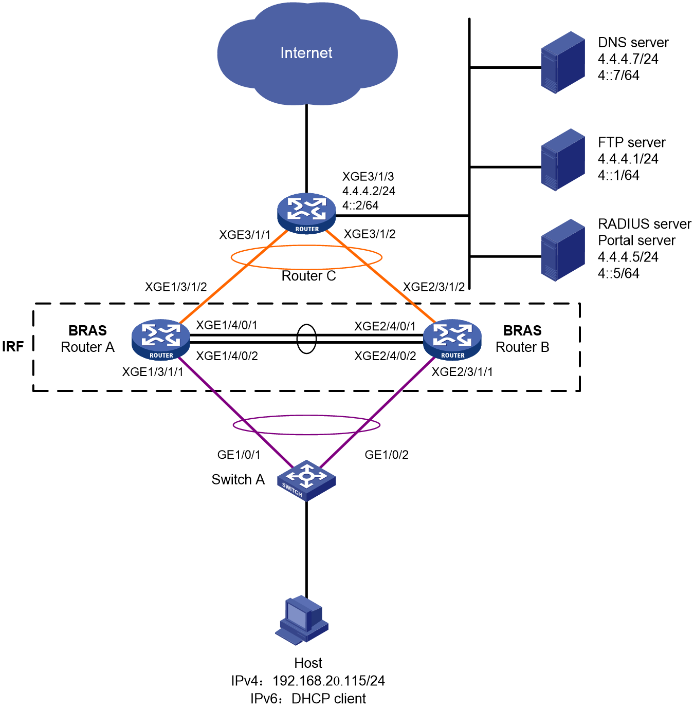
Table 17 IP address planning table
|
Device |
Interface |
IP address |
Device |
Interface |
IP address |
|
DNS server |
N/A |
4.4.4.7/24 4::7/64 |
IRF fabric (BRAS) |
RAGG1 |
N/A |
|
FTP server |
N/A |
4.4.4.1/24 4::1/64 |
|
RAGG1023 |
100.1.1.1/24 100::1/64 |
|
RADIUS server and portal server |
|
4.4.4.5/24 4::5/64 |
|
XGE1/3/1/1 |
N/A |
|
Router C |
RAGG1023 |
100.1.1.2/24 100::2/64 |
|
XGE2/3/1/1 |
N/A |
|
|
XGE3/1/1 |
N/A |
|
XGE1/3/1/2 |
N/A |
|
|
XGE3/1/2 |
N/A |
|
XGE2/3/1/2 |
N/A |
|
|
XGE3/1/3 |
4.4.4.2/24 4::2/64 |
|
LoopBack1 |
80.1.1.1/32 80::1/128 |
Analysis
· To prevent single points of failure from affecting normal service traffic forwarding, configure multichassis link aggregation on the IRF fabric for service traffic forwarding.
· To minimize the impacts of IRF split on services, configure LACP MAD on the IRF fabric. You only need to configure LACP MAD on one aggregate interface. LACP MAD requires an IRF-capable intermediate device running software that can recognize and process LACPDUs containing the ActiveID field. In this example, Switch A is used as the intermediate device for LACP MAD.
· To guarantee bandwidth for users, authorize CAR actions to users for rate limiting.
· For the inbound traffic in the IPoE Web preauthentication domain, configure the following traffic classes and behaviors:
¡ Configure a traffic class to match traffic destined for the DNS server in a user group that accommodates users in the preauthentication domain, and configure the filter permit traffic behavior accordingly. The user group that accommodates users in the preauthentication domain is referred to as the preauthentication user group for simplicity in this example.
¡ Configure a traffic class to match traffic destined for the portal server in the preauthentication user group, and configure the filter permit traffic behavior accordingly.
¡ Configure a traffic class to match traffic destined for the internal network server in the preauthentication user group, and configure the filter permit traffic behavior accordingly.
¡ Configure a traffic class to match HTTP traffic in the preauthentication user group, and configure the redirect http-to-cpu traffic behavior accordingly.
¡ Configure a traffic class to match HTTPS traffic in the preauthentication user group, and configure the redirect https-to-cpu traffic behavior accordingly.
¡ Configure a traffic class to match IP traffic in the preauthentication user group, and configure the redirect cpu traffic behavior accordingly. (The configuration is required only for transparent authentication.)
¡ Configure a traffic class to match IP traffic in the preauthentication user group, and configure the filter deny traffic behavior accordingly.
· For the outbound traffic in the IPoE Web preauthentication domain, configure the following traffic classes and behaviors:
¡ Configure a traffic class to match traffic from the DNS server in the preauthentication user group, and configure the filter permit traffic behavior accordingly.
¡ Configure a traffic class to match traffic from the portal server in the preauthentication user group, and configure the filter permit traffic behavior accordingly.
¡ Configure a traffic class to match traffic from the internal network server in the preauthentication user group, and configure the filter permit traffic behavior accordingly.
¡ Configure a traffic class to match IP traffic in the preauthentication user group, and configure the filter deny traffic behavior accordingly.
Restrictions and guidelines
To prevent port conflicts from causing service unavailability, make sure the listening port numbers are not well-known port numbers or port numbers used by other TCP-based services. To view the TCP port numbers already used by services, use the display tcp command.
Procedure
Configuring IP addresses and routes
# On Router C, assign an IPv4 address and an IPv6 address to Ten-GigabitEthernet 3/1/3 (the interface connected to the servers).
<RouterC> system-view
[RouterC] interface ten-gigabitethernet 3/1/3
[RouterC-Ten-GigabitEthernet3/1/3] ip address 4.4.4.2 24
[RouterC-Ten-GigabitEthernet3/1/3] ipv6 address 4::2 64
[RouterC-Ten-GigabitEthernet3/1/3] quit
# On Router C, configure static routes destined for users.
[RouterC] ip route-static 192.168.0.0 24 100.1.1.1
[RouterC] ipv6 route-static 192:: 64 100::1
Configuring the DNS server
Configure the DNS server correctly so that the server can resolve the IPv4 or IPv6 URL address corresponding to the Web authentication page (in this example, http://www.ipv4.web.com and http://www.ipv6.web.com) based on the first protocol stack type used by a dual-stack IPoE user when the user comes online.
In this example, Windows Server 2016 is used to describe the basic DNS server configuration.
To configure the DNS server:
1. Install the DNS component:
a. Log in to the server, click Start, and then select Server Manager.
b. Click Add roles and features.
c. In the Before You Begin step, click Next.
d. In the Installation Type step, use the default setting, which is role-based or feature-based installation, and then click Next.
e. In the Server Selection step, use the default setting, which is Select a server from the server pool, and then click Next.
f. In the Server Roles step, select DNS Server. In the wizard window that opens, click Add Features, and then click Next.
g. In the Features step, use the default settings, and then click Next.
h. In the DNS Server step, click Next.
i. In the Confirmation step, click Install and wait for the installation to complete.
j. In the Results step, click Close.
2. Create an IPv4 forward lookup zone:
a. In the Server Manager window, click Tools, and then select DNS.
b. In the DNS Manager window, right click Forward Lookup Zones, and then select New Zone.
c. In the New Zone Wizard window, click Next.
d. In the Zone Type step, select Primary zone, and then click Next.
e. In the Zone Name step, enter zone name ipv4.web.com.
f. In the Zone File step, use the default settings, and then click Next.
g. In the Dynamic Update step, select Do not allow dynamic updates, and then click Next.
h. Click Finish.
i. In the DNS Manager window, click Forward Lookup Zones, right click ipv4.web.com, and then select New Host.
j. In the New Host window, enter host name www and IP address 4.4.4.7, and then click Add Host.
3. Create an IPv4 reverse lookup zone:
a. In the DNS Manager window, right click Reverse Lookup Zones, and then select New Zone.
b. In the New Zone Wizard window, click Next.
c. In the Zone Type step, select Primary zone, and then click Next.
d. In the Reverse Lookup Zone Name step, select IPv4 Reverse Lookup Zone, and then click Next.
e. Enter network ID 4.4.4, and then click Next.
f. In the Zone File step, use the default settings, and then click Next.
g. In the Dynamic Update step, select Do not allow dynamic updates, and then click Next.
h. Click Finish.
i. In the DNS Manager window, click Reverse Lookup Zones, right click 4.4.4.in-addr.arpa.dns, and then select New Pointer.
j. In the New Resource Record window, enter host IP address 4.4.4.7 and host name www.ipv4.web.com, and then click OK.
4. Create an IPv6 forward lookup zone:
a. In the Server Manager window, click Tools, and then select DNS.
b. In the DNS Manager window, right click Forward Lookup Zones, and then select New Zone.
c. In the New Zone Wizard window, click Next.
d. In the Zone Type step, select Primary zone, and then click Next.
e. In the Zone Name step, enter zone name ipv6.web.com.
f. In the Zone File step, use the default settings, and then click Next.
g. In the Dynamic Update step, select Do not allow dynamic updates, and then click Next.
h. Click Finish.
i. In the DNS Manager window, click Forward Lookup Zones, right click ipv6.web.com, and then select New Host.
j. In the New Host window, enter host name www and IP address 4::7, and then click Add Host.
5. Create an IPv6 reverse lookup zone:
a. In the DNS Manager window, right click Reverse Lookup Zones, and then select New Zone.
b. In the New Zone Wizard window, click Next.
c. In the Zone Type step, select Primary zone, and then click Next.
d. In the Reverse Lookup Zone Name step, select IPv6 Reverse Lookup Zone, and then click Next.
e. Enter network ID 4000:0000:0000:0000::/64, and then click Next.
f. In the Zone File step, use the default settings, and then click Next.
g. In the Dynamic Update step, select Do not allow dynamic updates, and then click Next.
h. Click Finish.
i. In the DNS Manager window, click Reverse Lookup Zones, right click 0.0.0.0.0.0.0.0.0.0.0.0.0.0.0.4.in-addr.arpa.dns, and then select New Pointer.
j. In the New Resource Record window, enter host IP address 4000.0000.0000.0000.0000.0000.0000.0007 and host name www.ipv6.web.com, and then click OK.
Configuring the RADIUS server and portal server
In this example, Srun 4.0.9 is installed on the server.
To configure the RADIUS server and portal server:
1. Enter http://4.4.4.5:8081 in the address bar of a Web browser, log in to the server, and add an access device:
# Open the page for managing devices, click the tab for adding devices, and add a device.
¡ Set the device name to BRAS.
¡ Use the IP address of Loopback 1 on the BRAS device as the NAS IP address. In this example, the IP address is 80.1.1.1.
¡ Use IP address 4.4.4.5 as ours IP address.
¡ Select NAS types Huawei, H3C, and Srun gateway.
¡ Set the DM port to 3799.
¡ Set the RADIUS key to 123456.
¡ Select to not discard traffic.
¡ Select H3C and Huawei (h3c v1.2) as the portal protocols.
¡ Set the portal key to 123456.
# Configure RADIUS trust settings:
a. Enter the RADIUS page, and click the link for accessing the RADIUS trust settings page.
b. On the page, continuously click Generate in the upper right corner until the generation succeeds.
c. Restart the Srun RADIUS process.
# Click the tab for configuring RADIUS service settings, and configure the system to validate usernames with the domain name.
2. Enter https://4.4.4.5:8080 in the address bar of a Web browser, log in to the server, and add a user:
a. Click the tab for managing and adding users, and then add a user.
b. Set the account name to user1 and the password to pass.
3. To deploy other settings such as control policies and product policies, see the manuals for the Srun server.
Setting up an IRF fabric
1. Use Router A and Router B to set up an IRF fabric:
# Assign member ID 1 to Router A, and bind Ten-GigabitEthernet 4/0/1 and Ten-GigabitEthernet 4/0/2 to IRF-port 2.
<RouterA> system-view
[RouterA] irf member 1 priority 2
[RouterA] interface ten-gigabitethernet 4/0/1
[RouterA-Ten-GigabitEthernet4/0/1] port link-mode bridge
[RouterA-Ten-GigabitEthernet4/0/1] quit
[RouterA] interface ten-gigabitethernet 4/0/2
[RouterA-Ten-GigabitEthernet4/0/2] port link-mode bridge
[RouterA-Ten-GigabitEthernet4/0/2] quit
[RouterA] irf-port 2
[RouterA-irf-port2] port group interface ten-gigabitethernet 4/0/1
[RouterA-irf-port2] port group interface ten-gigabitethernet 4/0/2
[RouterA-irf-port2] quit
# Save the running configuration to the main next-startup configuration file.
[RouterA] quit
<RouterA> save
# Enable IRF mode.
<RouterA> system-view
[RouterA] chassis convert mode irf
The device will switch to IRF mode and reboot. Continue?[Y/N]:y
You are recommended to save the current running configuration and specify the configuration file for the next startup. Now save the running configuration to the next-startup configuration file? [Y/N]:y
Please input the file name(*.cfg)[cfa0:/test.cfg]
(To leave the existing filename unchanged, press the enter key):
cfa0:/test.cfg exists, overwrite? [Y/N]:y
Validating file. Please wait...
Saved the current configuration to mainboard device successfully.
Do you want to convert the content of the next startup configuration file cfa0:/test.cfg to make it available in IRF mode? [Y/N]:y
Now rebooting, please wait...
A single-member IRF fabric that contains only Router A is set up after the router reboots.
# Assign member ID 2 to Router B, and bind Ten-GigabitEthernet 4/0/1 and Ten-GigabitEthernet 4/0/2 to IRF-port 1.
<RouterB> system-view
[RouterB] irf member 2 priority 1
[RouterB] interface ten-gigabitethernet 4/0/1
[RouterB-Ten-GigabitEthernet4/0/1] port link-mode bridge
[RouterB-Ten-GigabitEthernet4/0/1] quit
[RouterB] interface ten-gigabitethernet 4/0/2
[RouterB-Ten-GigabitEthernet4/0/2] port link-mode bridge
[RouterB-Ten-GigabitEthernet4/0/2] quit
[RouterB] irf-port 1
[RouterB-irf-port1] port group interface ten-gigabitethernet 4/0/1
[RouterB-irf-port1] port group interface ten-gigabitethernet 4/0/2
[RouterB-irf-port1] quit
# Save the running configuration to the main next-startup configuration file.
[RouterB] quit
<RouterB> save
# Enable IRF mode.
<RouterB> system-view
[RouterB] chassis convert mode irf
The device will switch to IRF mode and reboot. Continue?[Y/N]:y
You are recommended to save the current running configuration and specify the configuration file for the next startup. Now save the running configuration to the next-startup configuration file? [Y/N]:y
Please input the file name(*.cfg)[cfa0:/test.cfg]
(To leave the existing filename unchanged, press the enter key):
cfa0:/test.cfg exists, overwrite? [Y/N]:y
Validating file. Please wait...
Saved the current configuration to mainboard device successfully.
Do you want to convert the content of the next startup configuration file cfa0:/test.cfg to make it available in IRF mode? [Y/N]:y
Now rebooting, please wait...
Router B joins the IRF fabric that contains Router A after it reboots.
2. Configure downlink services for the IRF fabric:
a. Configure LACP MAD:
In this example, Router A acts as the master device in the IRF fabric and acts as a BRAS device in IPoE. For ease of understanding, Router A will be referred to as IRF in the subsequent IRF configuration steps and as BRAS in the subsequent IPoE configuration steps.
After the IRF fabric is established, you can configure settings for service modules. Once the IRF fabric is established, you can log in to the IRF fabric from any member device for configuration. By default, the device name of the IRF fabric is the name of the master device. In this example, the master device is Router A.
# Create Route-Aggregation 1 (the Layer 3 aggregate interface connected to Switch A), configure the aggregation group to operate in dynamic aggregation mode, and enable LACP MAD on the aggregate interface.
<IRF> system-view
[IRF] interface route-aggregation 1
[IRF-Route-Aggregation1] link-aggregation mode dynamic
[IRF-Route-Aggregation1] mad enable
You need to assign a domain ID (range: 0-4294967295)
[Current domain is: 0]:
The assigned domain ID is: 0
MAD LACP only enable on dynamic aggregation interface.
[IRF-Route-Aggregation1] quit
# Assign interfaces connected to Switch A to Layer 3 aggregation group 1.
[IRF] interface ten-gigabitethernet 1/3/1/1
[IRF-Ten-GigabitEthernet1/3/1/1] port link-aggregation group 1
[IRF-Ten-GigabitEthernet1/3/1/1] quit
[IRF] interface ten-gigabitethernet 2/3/1/1
[IRF-Ten-GigabitEthernet2/3/1/1] port link-aggregation group 1
[IRF-Ten-GigabitEthernet2/3/1/1] quit
b. Configure Switch A:
# Create Bridge-Aggregation 1 (the Layer 2 aggregate interface connected to the IRF fabric), and configure the aggregation group to operate in dynamic aggregation mode. The aggregate interface will be used for IRF LACP MAD.
<SwitchA> system-view
[SwitchA] interface bridge-aggregation 1
[SwitchA-Bridge-Aggregation1] link-aggregation mode dynamic
[SwitchA-Bridge-Aggregation1] quit
# Assign interfaces connected to the IRF fabric to Layer 2 aggregation group 1.
[SwitchA] interface gigabitethernet 1/0/1
[SwitchA-GigabitEthernet1/0/1] port link-aggregation group 1
[SwitchA-GigabitEthernet1/0/1] quit
[SwitchA] interface gigabitethernet 1/0/2
[SwitchA-GigabitEthernet1/0/2] port link-aggregation group 1
[SwitchA-GigabitEthernet1/0/2] quit
3. Configure uplink services for the IRF fabric:
a. Configure aggregation group settings on the IRF fabric:
# Create Route-Aggregation 1023 (the Layer 3 aggregate interface connected to Router C), configure the aggregation group to operate in dynamic aggregation mode, and assign an IPv4 address and an IPv6 address to the aggregate interface.
[IRF] interface route-aggregation 1023
[IRF-Route-Aggregation1023] link-aggregation mode dynamic
[IRF-Route-Aggregation1023] ip address 100.1.1.1 24
[IRF-Route-Aggregation1023] ipv6 address 100::1 64
[IRF-Route-Aggregation1023] quit
# Assign interfaces connected to Router C to Layer 3 aggregation group 1023.
[IRF] interface ten-gigabitethernet 1/3/1/2
[IRF-Ten-GigabitEthernet1/3/1/2] port link-aggregation group 1023
[IRF-Ten-GigabitEthernet1/3/1/2] quit
[IRF] interface ten-gigabitethernet 2/3/1/2
[IRF-Ten-GigabitEthernet2/3/1/2] port link-aggregation group 1023
[IRF-Ten-GigabitEthernet2/3/1/2] quit
# Configure static routes destined for Router C (for accessing servers and the Internet).
[IRF] ip route-static 0.0.0.0 0 100.1.1.2
[IRF] ipv6 route-static :: 0 100::2
b. Configure Router C:
In this example, the configuration steps only cover the IRF-side settings. The routing protocol used for the external network is not described.
# Create Route-Aggregation 1023 (the Layer 3 aggregate interface connected to the IRF fabric), configure the aggregation group to operate in dynamic aggregation mode, and assign an IPv4 address and an IPv6 address to the aggregate interface.
<RouterC> system-view
[RouterC] interface route-aggregation 1023
[RouterC-Route-Aggregation1023] link-aggregation mode dynamic
[RouterC-Route-Aggregation1023] ip address 100.1.1.2 24
[RouterC-Route-Aggregation1023] ipv6 address 100::2 64
[RouterC-Route-Aggregation1023] quit
# Assign interfaces connected to the IRF fabric to Layer 3 aggregation group 1023.
[RouterC] interface ten-gigabitethernet 3/1/1
[RouterC-Ten-GigabitEthernet3/1/1] port link-aggregation group 1023
[RouterC-Ten-GigabitEthernet3/1/1] quit
[RouterC] interface ten-gigabitethernet 3/1/2
[RouterC-Ten-GigabitEthernet3/1/2] port link-aggregation group 1023
[RouterC-Ten-GigabitEthernet3/1/2] quit
Configuring BRAS settings
1. Configure the DHCP server:
# Enable DHCP globally.
[BRAS] dhcp enable
# Enable the DHCP server to return a DHCP-NAK message if the client notions of their IP addresses are incorrect.
[BRAS] dhcp server request-ip-address check
# Create a local BAS IPv4 address pool named pool1 and enter its view.
[BRAS] ip pool pool1 bas local
# Specify the gateway address and DNS server address in the address pool, and exclude the gateway address and the specified user address of the static IPoE session from the address pool.
[BRAS-ip-pool-pool1] gateway 192.168.0.1 24
[BRAS-ip-pool-pool1] forbidden-ip 192.168.0.1
[BRAS-ip-pool-pool1] forbidden-ip 192.168.0.2
[BRAS-ip-pool-pool1] dns-list 4.4.4.7
[BRAS-ip-pool-pool1] quit
# Create an IPv6 address pool named pool2 and enter its view.
[BRAS] ipv6 pool pool2
# Specify primary subnet 192::/64 for dynamic allocation and DNS server 4::7 in address pool pool2.
[BRAS-ipv6-pool-pool2] network 192::/64 export-route
[BRAS-ipv6-pool-pool2] dns-server 4::7
[BRAS-ipv6-pool-pool2] quit
# Enable the DHCPv6 server on Route-Aggregation 1.
[BRAS] interface route-aggregation 1
[BRAS–Route-Aggregation1] ipv6 dhcp select server
2. Configure basic IPv6 settings:
# Automatically generate a link-local address for Route-Aggregation 1. This link-local address will be used as the gateway address of users.
[BRAS–Route-Aggregation1] ipv6 address auto link-local
# (Optional.) Configure DHCP flood attack protection on Route-Aggregation 1.
[BRAS–Route-Aggregation1] dhcp flood-protection enable
[BRAS–Route-Aggregation1] ipv6 dhcp flood-protection enable
# Disable RA message suppression on Route-Aggregation 1. Set the managed address configuration flag (M) to 1 in RA advertisements to be sent. Then, the host uses a DHCPv6 server to obtain IPv6 addresses. Set the other stateful configuration flag (O) to 1 in RA advertisements to be sent. Then, the host uses a DHCPv6 server to obtain configuration information other than IPv6 addresses.
[BRAS–Route-Aggregation1] undo ipv6 nd ra halt
[BRAS–Route-Aggregation1] ipv6 nd autoconfig managed-address-flag
[BRAS–Route-Aggregation1] ipv6 nd autoconfig other-flag
[BRAS–Route-Aggregation1] quit
3. Configure the portal authentication server:
# Create an IPv4 portal authentication server named newpt1, configure its IP address as 4.4.4.5, and set its key to 123456 in plaintext form.
[BRAS] portal server newpt1
[BRAS-portal-server-newpt1] ip 4.4.4.5 key simple 123456
[BRAS-portal-server-newpt1] quit
# Create an IPv6 portal authentication server named newpt2, configure its IPv6 address as 4::5, and set its key to 123456 in plaintext form.
[BRAS] portal server newpt2
[BRAS-portal-server-newpt2] ipv6 4::5 key simple 123456
[BRAS-portal-server-newpt2] quit
4. Configure the HTTPS redirect listening port number:
# Specify 11111 as the HTTPS redirect listening port number. Make sure the port number is not used by any other service. To see the TCP port numbers used by other services, execute the display tcp command.
[BRAS] http-redirect https-port 11111
5. Configure the BRAS to get user access information from ARP and ND entries:
# Configure the BRAS to get user access information from ARP and ND entries.
[BRAS] portal access-info trust arp
[BRAS] portal access-info trust nd
6. Create a local user group:
# Create a user group named pre for preauthentication.
[BRAS] user-group pre
New user group added.
[BRAS-ugroup-pre] quit
7. Configure QoS settings:
a. Configure ACLs for preauthentication:
# Create an IPv4 and IPv6 advanced ACL named dns_permit separately. Configure a rule to permit all packets destined for the DNS server from users in user group pre.
[BRAS] acl advanced name dns_permit
[BRAS-acl-ipv4-adv-dns_permit] rule 0 permit ip destination 4.4.4.7 0 user-group pre
[BRAS-acl-ipv4-adv-dns_permit] quit
[BRAS] acl ipv6 advanced name dns_permit
[BRAS-acl-ipv6-adv-dns_permit] rule 0 permit ipv6 destination 4::7 128 user-group pre
[BRAS-acl-ipv6-adv-dns_permit] quit
# Create an IPv4 and IPv6 advanced ACL named web_permit separately. Configure a rule to permit all packets destined for the portal server from users in user group pre.
[BRAS] acl advanced name web_permit
[BRAS-acl-ipv4-adv-web_permit] rule 0 permit ip destination 4.4.4.5 0 user-group pre
[BRAS-acl-ipv4-adv-web_permit] quit
[BRAS] acl ipv6 advanced name web_permit
[BRAS-acl-ipv6-adv-web_permit] rule 0 permit ipv6 destination 4::5 128 user-group pre
[BRAS-acl-ipv6-adv-web_permit] quit
# Create an IPv4 and IPv6 advanced ACL named neiwang separately. Configure a rule to permit all packets destined for the internal network server from users in user group pre.
[BRAS] acl advanced name neiwang
[BRAS-acl-ipv4-adv-neiwang] rule 0 permit ip destination 4.4.4.1 0 user-group pre
[BRAS-acl-ipv4-adv-neiwang] quit
[BRAS] acl ipv6 advanced name neiwang
[BRAS-acl-ipv6-adv-neiwang] rule 0 permit ipv6 destination 4::1 128 user-group pre
[BRAS-acl-ipv6-adv-neiwang] quit
# Create an IPv4 and IPv6 advanced ACL named web_http separately. Configure a rule to permit TCP packets with the destination port 80 and 8080 (HTTP packets) from users in user group pre.
[BRAS] acl advanced name web_http
[BRAS-acl-ipv4-adv-web_http] rule 0 permit tcp destination-port eq www user-group pre
[BRAS-acl-ipv4-adv-web_http] rule 5 permit tcp destination-port eq 8080 user-group pre
[BRAS-acl-ipv4-adv-web_http] quit
[BRAS] acl ipv6 advanced name web_http
[BRAS-acl-ipv6-adv-web_http] rule 0 permit tcp destination-port eq www user-group pre
[BRAS-acl-ipv6-adv-web_http] rule 5 permit tcp destination-port 8080 www user-group pre
[BRAS-acl-ipv6-adv-web_http] quit
# Create an IPv4 and IPv6 advanced ACL named web_https separately, and configure a rule to permit TCP packets with the destination port 443 (HTTPS packets) from users in user group pre.
[BRAS] acl advanced name web_https
[BRAS-acl-ipv4-adv-web_https] rule 0 permit tcp destination-port eq 443 user-group pre
[BRAS-acl-ipv4-adv-web_https] quit
[BRAS] acl ipv6 advanced name web_https
[BRAS-acl-ipv6-adv-web_https] rule 0 permit tcp destination-port eq 443 user-group pre
[BRAS-acl-ipv6-adv-web_https] quit
# Create an IPv4 and IPv6 advanced ACL named ip separately, and configure a rule to permit IP packets from users in user group pre.
[BRAS] acl advanced name ip
[BRAS-acl-ipv4-adv-ip] rule 0 permit ip user-group pre
[BRAS-acl-ipv4-adv-ip] quit
[BRAS] acl ipv6 advanced name ip
[BRAS-acl-ipv6-adv-ip] rule 0 permit ipv6 user-group pre
[BRAS-acl-ipv6-adv-ip] quit
# Create an IPv4 and IPv6 advanced ACL named neiwang_out separately, and configure a rule to permit IP packets from the internal network server in user group pre.
[BRAS] acl advanced name neiwang_out
[BRAS-acl-ipv4-adv-neiwang_out] rule 0 permit ip source 4.4.4.1 0 user-group pre
[BRAS-acl-ipv4-adv-neiwang_out] quit
[BRAS] acl ipv6 advanced name neiwang_out
[BRAS-acl-ipv6-adv-neiwang_out] rule 0 permit ipv6 source 4::1 128 user-group pre
[BRAS-acl-ipv6-adv-neiwang_out] quit
# Create an IPv4 and IPv6 advanced ACL named web_out separately, and configure a rule to permit IP packets from the portal server in user group pre.
[BRAS] acl advanced name web_out
[BRAS-acl-ipv4-adv-web_out] rule 0 permit ip source 4.4.4.5 0 user-group pre
[BRAS-acl-ipv4-adv-web_out] quit
[BRAS] acl ipv6 advanced name web_out
[BRAS-acl-ipv6-adv-web_out] rule 0 permit ipv6 source 4::5 128 user-group pre
[BRAS-acl-ipv6-adv-web_out] quit
# Create an IPv4 and IPv6 advanced ACL named dns_out separately, and configure a rule to permit IP packets from the DNS server in user group pre.
[BRAS] acl advanced name dns_out
[BRAS-acl-ipv4-adv-dns_out] rule 0 permit ip source 4.4.4.7 0 user-group pre
[BRAS-acl-ipv4-adv-dns_out] quit
[BRAS] acl ipv6 advanced name dns_out
[BRAS-acl-ipv6-adv-dns_out] rule 0 permit ipv6 source 4::7 128 user-group pre
[BRAS-acl-ipv6-adv-dns_out] quit
b. Configure QoS traffic classes for preauthentication users:
# Create traffic class dns_permit and specify ACL dns_permit as the match criterion.
[BRAS] traffic classifier dns_permit operator or
[BRAS-classifier-dns_permit] if-match acl name dns_permit
[BRAS-classifier-dns_permit] if-match acl ipv6 name dns_permit
[BRAS-classifier-dns_permit] quit
# Create traffic class web_permit and specify ACL web_permit as the match criterion.
[BRAS] traffic classifier web_permit operator or
[BRAS-classifier-web_permit] if-match acl name web_permit
[BRAS-classifier-web_permit] if-match acl ipv6 name web_permit
[BRAS-classifier-web_permit] quit
# Create traffic class neiwang and specify ACL neiwang as the match criterion.
[BRAS] traffic classifier neiwang operator or
[BRAS-classifier-neiwang] if-match acl name neiwang
[BRAS-classifier-neiwang] if-match acl ipv6 name neiwang
[BRAS-classifier-neiwang] quit
# Create traffic class web_http and specify ACL web_http as the match criterion.
[BRAS] traffic classifier web_http operator or
[BRAS-classifier-web_http] if-match acl name web_http
[BRAS-classifier-web_http] if-match acl ipv6 name web_http
[BRAS-classifier-web_http] quit
# Create traffic class web_https and specify ACL web_https as the match criterion.
[BRAS] traffic classifier web_https operator or
[BRAS-classifier-web_https] if-match acl name web_https
[BRAS-classifier-web_https] if-match acl ipv6 name web_https
[BRAS-classifier-web_https] quit
# Create traffic class web_deny and specify ACL ip as the match criterion.
[BRAS] traffic classifier web_deny operator or
[BRAS-classifier-web_deny] if-match acl name ip
[BRAS-classifier-web_deny] if-match acl ipv6 name ip
[BRAS-classifier-web_deny] quit
# Create traffic class neiwang_out and specify ACL neiwang_out as the match criterion.
[BRAS] traffic classifier neiwang_out operator or
[BRAS-classifier-neiwang_out] if-match acl name neiwang_out
[BRAS-classifier-neiwang_out] if-match acl ipv6 name neiwang_out
[BRAS-classifier-neiwang_out] quit
# Create traffic class web_out and specify ACL web_out as the match criterion.
[BRAS] traffic classifier web_out operator or
[BRAS-classifier-web_out] if-match acl name web_out
[BRAS-classifier-web_out] if-match acl ipv6 name web_out
[BRAS-classifier-web_out] quit
# Create traffic class dns_out and specify ACL dns_out as the match criterion.
[BRAS] traffic classifier dns_out operator or
[BRAS-classifier-dns_out] if-match acl name dns_out
[BRAS-classifier-dns_out] if-match acl ipv6 name dns_out
[BRAS-classifier-dns_out] quit
c. Configure QoS traffic behaviors:
# Configure traffic behavior dns_permit to permit traffic to pass through without rate limiting or accounting.
[BRAS] traffic behavior dns_permit
[BRAS-behavior-dns_permit] filter permit
[BRAS-behavior-dns_permit] free account
[BRAS-behavior-dns_permit] quit
# Configure traffic behavior web_permit to permit traffic to pass through without rate limiting or accounting.
[BRAS] traffic behavior web_permit
[BRAS-behavior-web_permit] filter permit
[BRAS-behavior-web_permit] free account
[BRAS-behavior-web_permit] quit
# Configure traffic behavior neiwang to permit traffic to pass through without rate limiting or accounting.
[BRAS] traffic behavior neiwang
[BRAS-behavior-neiwang] filter permit
[BRAS-behavior-neiwang] free account
[BRAS-behavior-neiwang] quit
# Configure traffic behavior web_http to redirect HTTP packets to the CPU.
[BRAS] traffic behavior web_http
[BRAS-behavior-web_http] redirect http-to-cpu
[BRAS-behavior-web_http] quit
# Configure traffic behavior web_https to redirect HTTPS packets to the CPU.
[BRAS] traffic behavior web_https
[BRAS-behavior-web_https] redirect https-to-cpu
[BRAS-behavior-web_https] quit
# Configure traffic behavior web_deny to deny traffic.
[BRAS] traffic behavior web_deny
[BRAS-behavior-web_deny] filter deny
[BRAS-behavior-web_deny] free account
[BRAS-behavior-web_deny] quit
# Configure traffic behavior neiwang_out to permit traffic to pass through without rate limiting or accounting.
[BRAS] traffic behavior neiwang_out
[BRAS-behavior-neiwang_out] filter permit
[BRAS-behavior-neiwang_out] free account
[BRAS-behavior-neiwang_out] quit
# Configure traffic behavior web_out to permit traffic to pass through without rate limiting or traffic accounting.
[BRAS] traffic behavior web_out
[BRAS-behavior-web_out] filter permit
[BRAS-behavior-web_out] free account
[BRAS-behavior-web_out] quit
# Configure traffic behavior dns_out to permit traffic to pass through without rate limiting or traffic accounting.
[BRAS] traffic behavior dns_out
[BRAS-behavior-dns_out] filter permit
[BRAS-behavior-dns_out] free account
[BRAS-behavior-dns_out] quit
d. Configure QoS policies:
Create a QoS policy named web.
[BRAS] qos policy web
# Associate traffic classes with traffic behaviors to
permit packets destined for the DNS server, portal server, and internal network server to pass through and
redirect packets with destination port 80 (HTTP packets) and packets with destination port 443 (HTTPS packets) to the CPU.
All other packets are denied.
[BRAS-qospolicy-web] classifier dns_permit behavior dns_permit
[BRAS-qospolicy-web] classifier web_permit behavior web_permit
[BRAS-qospolicy-web] classifier neiwang behavior neiwang
[BRAS-qospolicy-web] classifier web_http behavior web_http
[BRAS-qospolicy-web] classifier web_https behavior web_https
[BRAS-qospolicy-web] classifier web_deny behavior web_deny
[BRAS-qospolicy-web] quit
# Create a QoS policy named out.
[BRAS] qos policy out
# Associate traffic classes with traffic behaviors to permit packets from the DNS server, portal server, and internal network server in user group pre to pass through. All other packets are denied.
[BRAS-qospolicy-out] classifier dns_out behavior dns_out
[BRAS-qospolicy-out] classifier web_out behavior web_out
[BRAS-qospolicy-out] classifier neiwang_out behavior neiwang_out
[BRAS-qospolicy-out] classifier web_deny behavior web_deny
[BRAS-qospolicy-out] quit
e. Apply the QoS policies:
# Apply QoS policy web to the inbound traffic globally. To identify whether the QoS policy takes effect, execute the display qos policy global inbound command.
[BRAS] qos apply policy web global inbound
# Apply QoS policy out to the outbound traffic globally. To identify whether the QoS policy takes effect, execute the display qos policy global outbound command.
[BRAS] qos apply policy out global outbound
8. Configure a RADIUS scheme:
# Create a RADIUS scheme named rs1 and enter its view.
[BRAS] radius scheme rs1
# Configure primary servers and keys for authentication and accounting.
[BRAS-radius-rs1] primary authentication 4.4.4.5
[BRAS-radius-rs1] primary accounting 4.4.4.5
[BRAS-radius-rs1] key authentication simple 123456
[BRAS-radius-rs1] key accounting simple 123456
# Exclude the ISP domain name from the usernames sent to the RADIUS servers.
[BRAS-radius-rs1] user-name-format without-domain
# Set the IPv4 NAS-IP address carried in RADIUS packets to 80.1.1.1.
[BRAS-radius-rs1] nas-ip 80.1.1.1
[BRAS-radius-rs1] quit
# Specify the RADIUS DAE client at 4.4.4.5, and set the shared key to 123456 in plaintext form for secure communication between the DAE server and client. Make sure the shared key is the same as the key configured on the RADIUS DAE client.
[BRAS] radius dynamic-author server
[BRAS-radius-da-server] client ip 4.4.4.5 key simple 123456
[BRAS-radius-da-server] quit
9. Configure the preauthentication ISP domain and Web authentication ISP domain:
# Configure ISP domain dm1 for IPoE user preauthentication.
[BRAS] domain name dm1
[BRAS-isp-dm1] authentication ipoe none
[BRAS-isp-dm1] authorization ipoe none
[BRAS-isp-dm1] accounting ipoe none
# Configure the authorization user group and IPv4 and IPv6 address pools in preauthentication ISP domain dm1.
[BRAS-isp-dm1] authorization-attribute user-group pre
[BRAS-isp-dm1] authorization-attribute ipv6-pool pool2
# Configure the Web authentication page URLs in ISP domain dm1.
[BRAS-isp-dm1] web-server url http://www.ipv4.web.com
[BRAS-isp-dm1] web-server ipv6-url http://www.ipv6.web.com
[BRAS-isp-dm1] quit
# Configure ISP domain dm2 for IPoE user Web authentication.
[BRAS] domain name dm2
[BRAS-isp-dm2] authentication ipoe radius-scheme rs1
[BRAS-isp-dm2] authorization ipoe radius-scheme rs1
[BRAS-isp-dm2] accounting ipoe radius-scheme rs1
[BRAS-isp-dm2] authorization-attribute car inbound cir 5120 outbound cir 5120
[BRAS-isp-dm2] quit
10. Configure IPoE:
# Enable IPoE and configure the Layer 2 access mode for users on Route-Aggregation 1.
[BRAS] interface route-aggregation 1
[BRAS–Route-Aggregation1] ip subscriber l2-connected enable
# Enable unclassified-IPv4 packet initiation and unclassified-IPv6 packet initiation with the matching-user keyword specified.
[BRAS–Route-Aggregation1] ip subscriber initiator unclassified-ip enable matching-user
[BRAS–Route-Aggregation1] ip subscriber initiator unclassified-ipv6 enable matching-user
# Configure the Web authentication method for IPoE users on Route-Aggregation 1.
[BRAS–Route-Aggregation1] ip subscriber authentication-method web
The operation may cut all users on this interface. Continue?[Y/N]:y
# Specify ISP domain dm1 as the Web preauthentication domain and ISP domain dm2 as the Web authentication domain on Route-Aggregation 1.
[BRAS–Route-Aggregation1] ip subscriber pre-auth domain dm1
[BRAS–Route-Aggregation1] ip subscriber web-auth domain dm2
[BRAS–Route-Aggregation1] quit
# Configure the statically configured IPv4 address as the IPoE static user address.
[BRAS] ip subscriber session static ip 192.168.0.2 domain dm1 interface route-aggregation 1 support-ds
11. Configure attack defense:
¡ Configure source MAC-based ARP attack detection:
# Enable source MAC-based ARP attack detection and specify the filter handling method.
[BRAS] arp source-mac filter
Set the check interval for source MAC-based ARP attack detection to 5 seconds.
[BRAS] arp source-mac check-interval 5
# Set the threshold for source MAC-based ARP attack detection to 30.
[BRAS] arp source-mac threshold 30
# Set the aging time for ARP attack entries to 300 seconds.
[BRAS] arp source-mac aging-time 300
¡ Configure source MAC-based ND attack detection:
# Enable source MAC-based ND attack detection and specify the filter handling method.
[BRAS] ipv6 nd source-mac filter
# Set the check interval for source MAC-based ND attack detection to 5 seconds.
[BRAS] ipv6 nd source-mac check-interval 5
# Set the threshold for source MAC-based ND attack detection to 30.
[BRAS] ipv6 nd source-mac threshold 30
# Set the aging time for ND attack entries to 300 seconds.
[BRAS] ipv6 nd source-mac aging-time 300
¡ Configure DHCP flood attack protection:
# Enable DHCP flood attack protection on Route-Aggregation 1.
[BRAS] interface route-aggregation 1
[BRAS-Route-Aggregation1] dhcp flood-protection enable
[BRAS–Route-Aggregation1] quit
# Configure the device to allow a maximum of 30 DHCP packets per 10000 milliseconds from each DHCP client.
[BRAS] dhcp flood-protection threshold 30 10000
# Set the DHCP flood attack entry aging time to 300 seconds.
[BRAS] dhcp flood-protection aging-time 300
¡ Configure DHCPv6 flood attack protection:
# Enable DHCPv6 flood attack protection on Route-Aggregation 1.
[BRAS] interface route-aggregation 1
[BRAS-Route-Aggregation1] ipv6 dhcp flood-protection enable
[BRAS-Route-Aggregation1] quit
# Configure the device to allow a maximum of 30 DHCPv6 packets per 10000 milliseconds from each DHCPv6 client.
[BRAS] ipv6 dhcp flood-protection threshold 30 10000
# Set the DHCPv6 flood attack entry aging time to 300 seconds.
[BRAS] ipv6 dhcp flood-protection aging-time 300
¡ Enable ICMP/ICMPv6 fast reply.
[BRAS] ip icmp fast-reply enable
[BRAS] ipv6 icmpv6 fast-reply enable
¡ Configure TCP SYN flood attack prevention:
# Enable flow-based TCP SYN flood attack prevention.
[BRAS] tcp anti-syn-flood flow-based enable
# Set the check interval to 20 seconds for flow-based TCP SYN flood attack prevention.
[BRAS] tcp anti-syn-flood flow-based check-interval 20
# Set the threshold to 2000 for triggering flow-based TCP SYN flood attack prevention.
[BRAS] tcp anti-syn-flood flow-based threshold 2000
# Set the flow-based TCP SYN flood attack prevention duration to 5 minutes.
[BRAS] tcp anti-syn-flood flow-based duration 5
¡ Configure HTTP/HTTPS attack defense:
# Enable destination IP-based IPoE HTTP/HTTPS attack defense.
[BRAS] ip subscriber http-defense destination-ip enable
# Trigger attack defense when the total number of HTTP/HTTPS packets sent to the same destination IP address within 300 seconds reaches 6000.
[BRAS] ip subscriber http-defense destination-ip threshold 6000 interval 300
¡ Enable HTTP packet fast reply:
# Enable HTTP packet fast reply on Route-Aggregation 1.
[BRAS] interface route-aggregation 1
[BRAS-Route-Aggregation1] ip subscriber http-fast-reply enable
[BRAS-Route-Aggregation1] quit
Verifying the configuration
# After the user passes authentication in the preauthentication domain, display information about online IPoE users to verify that the user has come online and obtained IPv4 address 192.168.0.2 and IPv6 address 192::2.
[BRAS] display access-user interface route-aggregation 1
UserID Interface IP address MAC address S-/C-VLAN
Username Access type
IPv6 address
0x5c RAGG1 192.168.0.2 000c-29a6-b656 -/-
000c29a6b656 L2 IPoE dynamic
192::2
# On the Web authentication page, enter the username and password, and then bring the user online. After the user passes Web authentication, display information about online IPoE users.
[BRAS] display access-user interface route-aggregation 1
UserID Interface IP address MAC address S-/C-VLAN
Username Access type
IPv6 address
0x5c RAGG1 192.168.0.2 000c-29a6-b656 -/-
user1 Web auth
192::2
Configuration files
· Router C:
#
interface Route-Aggregation1023
ip address 100.1.1.2 255.255.255.0
ipv6 address 100::2/64
link-aggregation mode dynamic
#
interface Ten-GigabitEthernet3/1/1
port link-aggregation group 1023
#
interface Ten-GigabitEthernet3/1/2
port link-aggregation group 1023
#
interface Ten-GigabitEthernet3/1/3
ip address 4.4.4.2 255.255.255.0
ipv6 address 4::2/64
#
ip route-static 192.168.0.0 24 100.1.1.1
ipv6 route-static 192:: 64 100::1
#
· IRF fabric (BRAS):
#
irf mac-address persistent always
irf auto-update enable
irf auto-merge enable
undo irf link-delay
irf member 1 priority 2
irf member 2 priority 1
#
irf-port 1/2
port group interface Ten-GigabitEthernet1/4/0/1 mode enhanced
port group interface Ten-GigabitEthernet1/4/0/2 mode enhanced
#
irf-port 2/1
port group interface Ten-GigabitEthernet2/4/0/1 mode enhanced
port group interface Ten-GigabitEthernet2/4/0/2 mode enhanced
#
dhcp enable
ip subscriber session static ip 192.168.0.2 domain dm1 interface route-aggregation 1 support-ds
#
traffic classifier dns_out operator or
if-match acl name dns_out
if-match acl ipv6 name dns_out
#
traffic classifier dns_permit operator or
if-match acl name dns_permit
if-match acl ipv6 name dns_permit
#
traffic classifier neiwang operator or
if-match acl name neiwang
if-match acl ipv6 name neiwang
#
traffic classifier neiwang_out operator or
if-match acl name neiwang_out
if-match acl ipv6 name neiwang_out
#
traffic classifier web_deny operator or
if-match acl name ip
if-match acl ipv6 name ip
#
traffic classifier web_http operator or
if-match acl name web_http
if-match acl ipv6 name web_http
#
traffic classifier web_https operator or
if-match acl name web_https
if-match acl ipv6 name web_https
#
traffic classifier web_out operator or
if-match acl name web_out
if-match acl ipv6 name web_out
#
traffic classifier web_permit operator or
if-match acl name web-permit
if-match acl ipv6 name web-permit
#
traffic behavior dns_out
filter permit
free account
#
traffic behavior dns_permit
filter permit
free account
#
traffic behavior neiwang
filter permit
free account
#
traffic behavior neiwang_out
filter permit
free account
#
traffic behavior web_deny
filter deny
free account
#
traffic behavior web_http
redirect http-to-cpu
#
traffic behavior web_https
redirect https-to-cpu
#
traffic behavior web_out
free account
#
traffic behavior web_permit
free account
#
qos policy out
classifier dns_out behavior dns_out
classifier web_out behavior web_out
classifier neiwang_out behavior neiwang_out
classifier web_deny behavior web_deny
#
qos policy web
classifier dns_permit behavior dns_permit
classifier web_permit behavior web_permit
classifier neiwang behavior neiwang
classifier web_http behavior web_http
classifier web_https behavior web_https
classifier web_deny behavior web_deny
#
ip pool pool1 bas local
gateway 192.168.0.1 mask 255.255.255.0
dns-list 4.4.4.7
forbidden-ip 192.168.0.1
forbidden-ip 192.168.0.2
#
ipv6 pool pool2
network 192::/64 export-route
dns-server 4::7
#
ipv6 dhcp server forbidden-address 192::1
#
interface Route-Aggregation1
link-aggregation mode dynamic
mad enable
dhcp flood-protection enable
ipv6 dhcp select server
ipv6 dhcp flood-protection enable
ipv6 address auto link-local
ipv6 nd autoconfig managed-address-flag
ipv6 nd autoconfig other-flag
undo ipv6 nd ra halt
ip subscriber l2-connected enable
ip subscriber http-fast-reply enable
ip subscriber initiator dhcpv6 enable
ip subscriber initiator unclassified-ip enable matching-user
ip subscriber initiator unclassified-ipv6 enable matching-user
ip subscriber initiator arp enable
ip subscriber authentication-method web
ip subscriber pre-auth domain dm1
ip subscriber web-auth domain dm2
#
interface Route-Aggregation1023
ip address 100.1.1.1 255.255.255.0
ipv6 address 100::1/64
link-aggregation mode dynamic
#
interface Ten-GigabitEthernet1/3/1/1
port link-aggregation group 1
#
interface Ten-GigabitEthernet2/3/1/1
port link-aggregation group 1
#
interface Ten-GigabitEthernet1/3/1/2
port link-aggregation group 1023
#
interface Ten-GigabitEthernet2/3/1/2
port link-aggregation group 1023
#
ip route-static 0.0.0.0 0 100.1.1.2
ipv6 route-static :: 0 100::2
#
qos apply policy web global inbound
qos apply policy out global outbound
#
acl advanced name dns_out
rule 0 permit ip source 4.4.4.7 0 user-group pre
#
acl advanced name dns_permit
rule 0 permit ip destination 4.4.4.7 0 user-group pre
#
acl advanced name ip
rule 0 permit ip user-group pre
#
acl advanced name neiwang
rule 0 permit ip destination 4.4.4.1 0 user-group pre
#
acl advanced name neiwang_out
rule 0 permit ip source 4.4.4.1 0 user-group pre
#
acl advanced name web_http
rule 0 permit tcp destination-port eq www user-group pre
rule 5 permit tcp destination-port eq 8080 user-group pre
#
acl advanced name web_https
rule 0 permit tcp destination-port eq 443 user-group pre
#
acl advanced name web_out
rule 0 permit ip source 4.4.4.5 0 user-group pre
#
acl advanced name web-permit
rule 0 permit ip destination 4.4.4.5 0 user-group pre
#
acl ipv6 advanced name dns_out
rule 0 permit ipv6 source 4::7/128 user-group pre
#
acl ipv6 advanced name dns_permit
rule 0 permit ipv6 destination 4::7/128 user-group pre
#
acl ipv6 advanced name ip
rule 0 permit ipv6 user-group pre
#
acl ipv6 advanced name neiwang
rule 0 permit ipv6 destination 4::1/128 user-group pre
#
acl ipv6 advanced name neiwang_out
rule 0 permit ipv6 source 4::1/128 user-group pre
#
acl ipv6 advanced name web-permit
rule 0 permit ipv6 destination 4::5/128 user-group pre
#
acl ipv6 advanced name web_http
rule 0 permit tcp destination-port eq www user-group pre
rule 5 permit tcp destination-port eq 8080 user-group pre
#
acl ipv6 advanced name web_https
rule 0 permit tcp destination-port eq 443 user-group pre
#
acl ipv6 advanced name web_out
rule 0 permit ipv6 source 4::5/128 user-group pre
#
radius scheme rs1
primary authentication 192.168.2.249
primary accounting 192.168.2.249
key authentication simple 123456
key accounting simple 123456
nas-ip 80.1.1.1
#
radius dynamic-author server
client ip 4.4.4.5 key simple 123456
#
domain name dm1
authorization-attribute user-group pre
authorization-attribute ipv6-pool pool2
authentication ipoe none
authorization ipoe none
accounting ipoe none
web-server url http://www.ipv4.web.com
web-server ipv6-url http://www.ipv6.web.com
#
domain name dm2
authorization-attribute car inbound cir 5120 outbound cir 5120
authentication ipoe radius-scheme rs1
authorization ipoe radius-scheme rs1
accounting ipoe radius-scheme rs1
#
user-group pre
#
portal server newpt1
ip 4.4.4.5 key simple 123456
#
portal server newpt2
ipv6 4::5 key simple 123456
#
portal access-info trust arp
portal access-info trust nd
#
http-redirect https-port 11111
#
tcp anti-syn-flood flow-based enable
tcp anti-syn-flood flow-based threshold 2000
tcp anti-syn-flood flow-based check-interval 20
#
ip icmp fast-reply enable
#
dhcp flood-protection threshold 30 10000
#
ipv6 dhcp flood-protection threshold 30 10000
#
ipv6 icmpv6 fast-reply enable
#
ip subscriber http-defense destination-ip enable
#
ipv6 nd source-mac filter
#
arp source-mac filter
#
IPoE Web dual-stack transparent MAC authentication configuration example (no authentication for IPv6)
As networks evolve towards IPv6, not all network resources fully support IPv6 for a period of time. Therefore, using IPv4/IPv6 dual stacks is necessary.
This example describes a basic IPv6 application scenario. During deployment, configure authentication for only IPv4, while allowing direct access to network resources without authentication for IPv6.
Network configuration
As shown in Figure 47, BRAS devices Router A and Router B in a school form an IRF fabric to provide IPoE access services for school users. The network requirements are as follows:
· The DHCP client accesses the BRAS in IPoE mode through a Layer 2 network.
· The BRAS acts a DHCP relay agent to request IP addresses from the remote DHCP server.
· A server deployed with Srun software acts as the RADIUS server, portal authentication server, and portal Web server.
· The FTP server is an internal network server.
· Set the speed limit after successful IPoE Web authentication to 5 Mbps.
· Configure basic attack protection features for some protocol packets (such as ARP and DHCP) on the BRAS to prevent illegal packets from impacting the network.
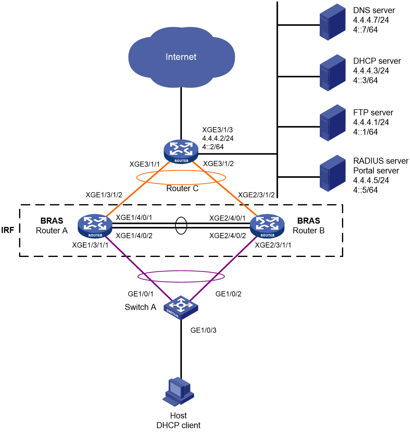
Table 18 IP address plan
|
Device |
Interface |
IP address |
Device |
Interface |
IP address |
|
DNS server |
N/A |
4.4.4.7/24 4::7/64 |
IRF (BRAS) |
RAGG1 |
192::1/64 |
|
DHCP server |
N/A |
4.4.4.3/24 4::3/64 |
|
RAGG1023 |
100.1.1.1/24 100::1/64 |
|
RADIUS server & Portal server |
N/A |
4.4.4.5/24 4::5/64 |
|
XGE1/3/1/1 |
N/A |
|
FTP server |
N/A |
4.4.4.1/24 4::1/64 |
|
XGE2/3/1/1 |
N/A |
|
Router C |
RAGG1023 |
100.1.1.2/24 100::2/64 |
|
XGE1/3/1/2 |
N/A |
|
|
XGE3/1/1 |
N/A |
|
XGE2/3/1/2 |
N/A |
|
|
XGE3/1/2 |
N/A |
|
LoopBack1 |
80.1.1.1/32 80::1/128 |
|
|
XGE3/1/3 |
4.4.4.2/24 4::2/64 |
|
|
|
Analysis
· To prevent single-point failures of member devices from affecting normal service forwarding, configure cross-member device aggregated ports for service forwarding in IRF.
· To minimize the impact of IRF fabric split on services, configure LACP MAD in IRF. Configure LACP MAD in only one aggregate interface. The intermediate device used for LACP MAD must be an H3C device with a software version that can recognize and process LACPDU protocol packets carrying ActiveID values. This example uses Switch A as the intermediate device for LACP MAD.
· To meet user bandwidth requirements, this example controls the rate through CAR authorization.
· Configure the following types of traffic classes and traffic behaviors to process incoming traffic in the IPoE Web preauthentication domain:
¡ Configure a class to match DNS traffic whose user group is marked in the preauthentication domain, and associate the class with a behavior containing the filter permit action.
¡ Configure a class to match portal authentication traffic whose user group is marked in the preauthentication domain, and associate the class with a behavior containing the filter permit action.
¡ Configure a class to match traffic to the internal network server with marked user group in the preauthentication domain, and associate the class with a behavior containing the filter permit action.
¡ Configure a class to match HTTP traffic whose user group is marked in the preauthentication domain, and associate the class with a behavior containing the redirect http-to-cpu action.
¡ Configure a class to match HTTPS traffic whose user group is marked in the preauthentication domain, and associate the class with a behavior containing the redirect https-to-cpu action.
¡ Configure a class to match IP traffic whose user group is marked in the preauthentication domain, and associate the class with a behavior containing the redirect cpu action. (Only for transparent authentication)
¡ Configure a class to match IP traffic whose user group is marked in the preauthentication domain, and associate the class with a behavior containing the filter deny action.
· Configure the following types of traffic classes and traffic behaviors to process outgoing traffic in the IPoE Web preauthentication domain:
¡ Configure a class to match DNS traffic whose user group is marked in the preauthentication domain, and associate the class with a behavior containing the filter permit action.
¡ Configure a class to match portal authentication traffic whose user group is marked in the preauthentication domain, and associate the class with a behavior containing the filter permit action.
¡ Configure a class to match traffic to the internal network server with marked user group in the preauthentication domain, and associate the class with a behavior containing the filter permit action.
¡ Configure a class to match IP traffic whose user group is marked in the preauthentication domain, and associate the class with a behavior containing the filter deny action.
Restrictions and guidelines
The DHCP server in this example is simulated by a device. As a best practice, use a dedicated DHCP server in actual applications.
To avoid service unavailability caused by port number conflicts, make sure the internal listening port number is not used by any well-known protocol and is not used by a TCP-based service. To view the TCP port numbers used by other services, execute the display tcp command.
Use NDRA to assign IPv6 addresses to the client, but allow direct access to network resources without authentication for IPv6 services.
Procedure
Configuring IP addresses and routes
# Assign IPv4 address 4.4.4.2/24 and IPv6 address 4::2/64 to Ten-GigabitEthernet 3/1/3 on Router C.
<RouterC> system-view
[RouterC] interface ten-gigabitethernet 3/1/3
[RouterC-Ten-GigabitEthernet3/1/3] ip address 4.4.4.2 24
[RouterC-Ten-GigabitEthernet3/1/3] ipv6 address 4::2 64
[RouterC-Ten-GigabitEthernet3/1/3] quit
# Configure a static route from Router C to the client.
[RouterC] ip route-static 192.168.0.0 24 100.1.1.1
[RouterC] ipv6 route-static 192:: 64 100::1
Configuring the DNS server
Configure the DNS server properly, so that the server can parse the IPv4 URL and IPv6 URL for corresponding Web authentication pages (http://www.ipv4.web.com and http://www.ipv6.web.com) according to the first stack through which dual-stack users come online.
|
|
NOTE: This section uses the Windows Server 2016 as an example to describe how to configure basic settings of the DNS server. |
1. Install the DNS component:
a. Log in to the server. Click Windows, and then select Server Manager.
b. Click Add roles and features.
c. On the Before You Begin page, click Next.
d. On the Installation Type page, use the default option (Role-based or feature-based installation), and then click Next.
e. On the Server Selection page, use the default option (Select a server from the server pool), and then click Next.
f. On the Server Roles page, select DNS Server.
g. On the Add Roles and Features Wizard that opens, click Add features and then click Next.
h. On the Features page, use the default setting, and then click Next.
i. On the DNS Server page, click Next.
j. On the Confirmation page, click Install, and wait for the installation to complete.
k. On the Results page, click Close.
2. Configuring an IPv4 forward lookup zone:
a. On the Server Manager page, click Tools, and then select DNS.
b. On the DNS Manager page, click Forward Lookup Zones, and then select New Zones....
c. On the New Zone Wizard page, click Next.
d. In the Zone Type area, select Primary zone, and then click Next.
e. In the Forward or Reverse Lookup Zone area, select Forward lookup zone, and then click Next.
f. In the Zone Name area, enter zone name ipv4.web.com.
g. In the Zone File area, use the default settings, and then click Next.
h. In the Dynamic Update area, click Do not allow dynamic updates, and then click Next.
i. Click Finish.
j. On the DNS Manager page, click Forward Lookup Zones, right-click ipv4.web.com, and then click New Host (A or AAAA)….
k. On the New Host page, enter name www and IP address 4.4.4.7, and then click Add Host.
3. Configuring an IPv4 reverse lookup zone:
a. On the DNS Manager page, click Reverse Lookup Zones, and then select New Zones....
b. On the New Zone Wizard page, click Next.
c. In the Zone Type area, select Primary zone, and then click Next.
d. In the Forward or Reverse Lookup Zone area, select Reverse lookup zone, and then click Next.
e. In the Reverse Lookup Zone Name area, select IPv4 Reverse Lookup Zone.
f. In the Reverse Lookup Zone Name area, enter network ID 4.4.4, and then click Next.
g. In the Zone File area, use the default settings, and then click Next.
h. In the Dynamic Update area, click Do not allow dynamic updates, and then click Next.
i. Click Finish.
j. On the DNS Manager page, click Reverse Lookup Zones, right-click 4.4.4.in-addr.arpa.dns, and then click New Pointer (PTR)….
k. On the New Resource Record page, enter host IP address 4.4.4.7 and host name www.ipv4.web.com, and then click OK.
4. Configuring an IPv6 forward lookup zone:
a. On the Server Manager page, click Tools, and then select DNS.
b. On the DNS Manager page, click Forward Lookup Zones, and then select New Zones....
c. On the New Zone Wizard page, click Next.
d. In the Zone Type area, select Primary zone, and then click Next.
e. In the Zone Name area, enter zone name ipv6.web.com.
f. In the Zone File area, use the default settings, and then click Next.
g. In the Dynamic Update area, click Do not allow dynamic updates, and then click Next.
h. Click Finish.
i. On the DNS Manager page, click Forward Lookup Zones, right-click ipv6.web.com, and then click New Host (A or AAAA)….
j. On the New Host page, enter name www and IP address 4::7, and then click Add Host.
5. Configuring an IPv6 reverse lookup zone:
a. On the DNS Manager page, click Reverse Lookup Zones, and then select New Zones....
b. On the New Zone Wizard page, click Next.
c. In the Zone Type area, select Primary zone, and then click Next.
d. In the Forward or Reverse Lookup Zone area, select Reverse lookup zone, and then click Next.
e. In the Reverse Lookup Zone Name area, select IPv6 Reverse Lookup Zone.
f. In the Reverse Lookup Zone Name area, enter network ID 4000:0000:0000:0000::/64, and then click Next.
g. In the Zone File area, use the default settings, and then click Next.
h. In the Dynamic Update area, click Do not allow dynamic updates, and then click Next.
i. Click Finish.
j. On the DNS Manager page, click Reverse Lookup Zones, right-click 0.0.0.0.0.0.0.0.0.0.0.0.0.0.0.4.in-addr.arpa.dns, and then click New Pointer (PTR)….
k. On the New Resource Record page, enter host IP address 4000.0000.0000.0000.0000.0000.0000.0007 and host name www.ipv6.web.com, and then click OK.
Configuring the DHCP server
# Enable DHCP.
<DHCP> system-view
[DHCP] dhcp enable
# Enable the DHCP server to return a DHCP-NAK message if the client notions of their IP addresses are incorrect.
[DHCP] dhcp server request-ip-address check
# Create address pool pool1 and enter its view.
[DHCP] ip pool pool1
# Specify primary subnet 192.168.0.0/24 for dynamic allocation in the address pool. Specify DNS server address 4.4.4.7 in the address pool.
[DHCP-ip-pool-pool1] network 192.168.0.0 24
[DHCP-ip-pool-pool1] dns-list 4.4.4.7
# Specify gateway address 192.168.0.1 for the address pool.
[DHCP-ip-pool-pool1] gateway-list 192.168.0.1
# Exclude IP address 192.168.0.1 from dynamic allocation.
[DHCP-ip-pool-pool1] forbidden-ip 192.168.0.1
[DHCP-ip-pool-pool1] quit
# Configure the default route. (The route below is used as an example. Configure the default route according to actual needs in the live network.)
[DHCP] ip route-static 0.0.0.0 0 4.4.4.2
Configuring the RADIUS server and portal server
|
|
NOTE: This section uses the Srun software of version 4.0.9 as an example to describe how to configure basic settings of the RADIUS server and portal server. |
1. Enter http://4.4.4.5:8081 in the address bar of a browser to log in to the server. Add access devices.
# Select Device Management from the navigation tree. Click the Add Label tab. On the tab, click Add.
¡ Set the device name to BRAS.
¡ Set the NAS IP to the IP address of interface LoopBack1 on BRAS. This example uses 80.1.1.1.
¡ Set the device IP to 4.4.4.5.
¡ Select Huawei, H3C, and Srun Gateways from the NAS type list.
¡ Set the DM port to 3799.
¡ Set the RADIUS key to 123456.
¡ Select No from the whether to drop traffic list.
¡ Select h3c v1.2 from the portal server list.
¡ Set the portal key to 123456.
# Set the RADIUS trust. Select RADIUS from the navigation tree. Click the RADIUS Trust Settings link to enter the RADIUS trust settings page. Click Generate in the upper right corner until the trust is successfully generated. Then restart Srun's RADIUS process.
# Click the RADIUS Service Settings tab, and specify the device to carry the ISP domain name in the usernames sent to the RADIUS server.
2. Enter https://4.4.4.5:8080 in the address bar of a browser to log in to the server. Add users.
Navigate to the User Management > Add Users page. Click Add to add a user with account user1 and password pass.
3. To deploy other configurations such as control policies and product policies, see the relevant Srun product documents.
Setting up IRF
1. Configure IRF on Router A and Router B:
# Assign member ID 1 and priority 2 to Router A. Bind Ten-GigabitEthernet 4/0/1 and Ten-GigabitEthernet 4/0/2 to IRF-port 2.
<RouterA> system-view
[RouterA] irf member 1 priority 2
[RouterA] interface ten-gigabitethernet 4/0/1
[RouterA-Ten-GigabitEthernet4/0/1] port link-mode bridge
[RouterA-Ten-GigabitEthernet4/0/1] quit
[RouterA] interface ten-gigabitethernet 4/0/2
[RouterA-Ten-GigabitEthernet4/0/2] port link-mode bridge
[RouterA-Ten-GigabitEthernet4/0/2] quit
[RouterA] irf-port 2
[RouterA-irf-port2] port group interface ten-gigabitethernet 4/0/1
[RouterA-irf-port2] port group interface ten-gigabitethernet 4/0/2
[RouterA-irf-port2] quit
# Save the current configurations to the next-startup configuration file.
[RouterA] quit
<RouterA> save
# Enable IRF mode.
<RouterA> system-view
[RouterA] chassis convert mode irf
The device will switch to IRF mode and reboot. Continue?[Y/N]:y
You are recommended to save the current running configuration and specify the configuration file for the next startup. Now save the running configuration to the next-startup configuration file? [Y/N]:y
Please input the file name(*.cfg)[cfa0:/test.cfg]
(To leave the existing filename unchanged, press the enter key):
cfa0:/test.cfg exists, overwrite? [Y/N]:y
Validating file. Please wait...
Saved the current configuration to mainboard device successfully.
Do you want to convert the content of the next startup configuration file cfa0:/test.cfg to make it available in IRF mode? [Y/N]:y
Now rebooting, please wait...
After rebooting, an IRF fabric with only one member device Router A is set up.
# Assign member ID 2 and priority 1 to Router B. Bind Ten-GigabitEthernet 4/0/1 and Ten-GigabitEthernet 4/0/2 to IRF-port 1.
<RouterB> system-view
[RouterB] irf member 2 priority 1
[RouterB] interface ten-gigabitethernet 4/0/1
[RouterB-Ten-GigabitEthernet4/0/1] port link-mode bridge
[RouterB-Ten-GigabitEthernet4/0/1] quit
[RouterB] interface ten-gigabitethernet 4/0/2
[RouterB-Ten-GigabitEthernet4/0/2] port link-mode bridge
[RouterB-Ten-GigabitEthernet4/0/2] quit
[RouterB] irf-port 1
[RouterB-irf-port1] port group interface ten-gigabitethernet 4/0/1
[RouterB-irf-port1] port group interface ten-gigabitethernet 4/0/2
[RouterB-irf-port1] quit
# Save the current configurations to the next-startup configuration file.
[RouterB] quit
<RouterB> save
# Enable IRF mode.
<RouterB> system-view
[RouterB] chassis convert mode irf
The device will switch to IRF mode and reboot. Continue?[Y/N]:y
You are recommended to save the current running configuration and specify the configuration file for the next startup. Now save the running configuration to the next-startup configuration file? [Y/N]:y
Please input the file name(*.cfg)[cfa0:/test.cfg]
(To leave the existing filename unchanged, press the enter key):
cfa0:/test.cfg exists, overwrite? [Y/N]:y
Validating file. Please wait...
Saved the current configuration to mainboard device successfully.
Do you want to convert the content of the next startup configuration file cfa0:/test.cfg to make it available in IRF mode? [Y/N]:y
Now rebooting, please wait...
An IRF fabric with member devices Router B and Router A is set up.
2. Configure downlink IRF services:
a. Configure LACP MAD:
|
|
NOTE: In this example, Router A acts as the master device in IRF and acts as the BRAS in IPoE. For ease of understanding, Router A is described as IRF in the IRF configuration section and described as BRAS in the IPoE configuration section. |
After the IRF fabric is set up, you can configure various service modules. Once the IRF fabric is set up, you can log in from any member device to configure the master device (Router A in this example) with default name Master.
# Create a dynamic aggregate interface Route-Aggregation 1 to connect to Switch A and enable LACP MAD.
<IRF> system-view
[IRF] interface route-aggregation 1
[IRF-Route-Aggregation1] link-aggregation mode dynamic
[IRF-Route-Aggregation1] mad enable
You need to assign a domain ID (range: 0-4294967295)
[Current domain is: 0]:
The assigned domain ID is: 0
MAD LACP only enable on dynamic aggregation interface.
[IRF-Route-Aggregation1] quit
# Assign the physical interfaces connecting to Switch A to Route-Aggregation 1.
[IRF] interface ten-gigabitethernet 1/3/1/1
[IRF-Ten-GigabitEthernet1/3/1/1] port link-aggregation group 1
[IRF-Ten-GigabitEthernet1/3/1/1] quit
[IRF] interface ten-gigabitethernet 2/3/1/1
[IRF-Ten-GigabitEthernet2/3/1/1] port link-aggregation group 1
[IRF-Ten-GigabitEthernet2/3/1/1] quit
b. Configure Switch A:
# Create a dynamic aggregate interface Route-Aggregation 1 to connect to the IRF fabric. This aggregate interface will be used for LACP MAD.
<SwitchA> system-view
[SwitchA] interface bridge-aggregation 1
[SwitchA-Bridge-Aggregation1] link-aggregation mode dynamic
[SwitchA-Bridge-Aggregation1] quit
# Assign the physical interfaces connecting to the IRF fabric to Route-Aggregation 1.
[SwitchA] interface gigabitethernet 1/0/1
[SwitchA-GigabitEthernet1/0/1] port link-aggregation group 1
[SwitchA-GigabitEthernet1/0/1] quit
[SwitchA] interface gigabitethernet 1/0/2
[SwitchA-GigabitEthernet1/0/2] port link-aggregation group 1
[SwitchA-GigabitEthernet1/0/2] quit
3. Configure uplink IRF services:
a. Configure a dynamic aggregation interface on the IRF fabric:
# Create a dynamic aggregate interface Route-Aggregation 1023 to connect to the egress router Router C, and assign IPv4 address 100.1.1.1/24 and IPv6 address 100::1/64 to the interface.
[IRF] interface route-aggregation 1023
[IRF-Route-Aggregation1023] link-aggregation mode dynamic
[IRF-Route-Aggregation1023] ip address 100.1.1.1 24
[IRF-Route-Aggregation1023] ipv6 address 100::1 64
[IRF-Route-Aggregation1023] quit
# Assign the physical interfaces connecting to Router C to Route-Aggregation 1023.
[IRF] interface ten-gigabitethernet 1/3/1/2
[IRF-Ten-GigabitEthernet1/3/1/2] port link-aggregation group 1023
[IRF-Ten-GigabitEthernet1/3/1/2] quit
[IRF] interface ten-gigabitethernet 2/3/1/2
[IRF-Ten-GigabitEthernet2/3/1/2] port link-aggregation group 1023
[IRF-Ten-GigabitEthernet2/3/1/2] quit
# Configure static default routes to Router C (for accessing the servers and the Internet).
[IRF] ip route-static 0.0.0.0 0 100.1.1.2
[IRF] ipv6 route-static :: 0 100::2
b. Configure Router C:
|
|
NOTE: This example describes only IRF-connection related configurations on the egress router, excluding the routing protocol configurations used by the external network. |
# Create a dynamic aggregate interface Route-Aggregation 1023 to connect to the IRF fabric, and assign IPv4 address 100.1.1.2/24 and IPv6 address 100::2/64 to the interface.
<RouterC> system-view
[RouterC] interface route-aggregation 1023
[RouterC-Route-Aggregation1023] link-aggregation mode dynamic
[RouterC-Route-Aggregation1023] ip address 100.1.1.2 24
[RouterC-Route-Aggregation1023] ipv6 address 100::2 64
[RouterC-Route-Aggregation1023] quit
# Assign the physical interfaces connecting to the IRF fabric to Route-Aggregation 1023.
[RouterC] interface ten-gigabitethernet 3/1/1
[RouterC-Ten-GigabitEthernet3/1/1] port link-aggregation group 1023
[RouterC-Ten-GigabitEthernet3/1/1] quit
[RouterC] interface ten-gigabitethernet 3/1/2
[RouterC-Ten-GigabitEthernet3/1/2] port link-aggregation group 1023
[RouterC-Ten-GigabitEthernet3/1/2] quit
Configuring BRAS
1. Configure DHCP relay:
# Enable DHCP globally.
[BRAS] dhcp enable
# Create DHCP relay address pool pool1, and specify the gateway address and DHCP server for the address pool.
[BRAS] ip pool pool1 bas remote
[BRAS-ip-pool-pool1] gateway 192.168.0.1 24
[BRAS-ip-pool-pool1] remote-server 4.4.4.3
[BRAS-ip-pool-pool1] quit
# Enable the DHCPv4 relay agent on Route-Aggregation 1.
[BRAS] interface route-aggregation 1
[BRAS–Route-Aggregation1] dhcp select relay
# Configure an IPv6 address for the interface.
[BRAS–Route-Aggregation1] ipv6 address 192::1 64
# Enable the interface to advertise RA messages.
[BRAS–Route-Aggregation1] undo ipv6 nd ra halt
[BRAS–Route-Aggregation1] quit
2. Configure a portal authentication server named newpt1, specify IP address 4.4.4.5 and plaintext shared key 123456 for the server.
[BRAS] portal server newpt1
[BRAS-portal-server-newpt1] ip 4.4.4.5 key simple 123456
[BRAS-portal-server-newpt1] quit
3. Specify the HTTPS redirect listening port number.
Make sure the port number does not conflict with existing port numbers. To view the TCP port numbers used by other services, execute the display tcp command.
[BRAS] http-redirect https-port 11111
4. Configure BRAS to obtain user information from ARP entries.
[BRAS] portal access-info trust arp
5. Create a user group named pre for the preauthentication domain.
[BRAS] user-group pre
New user group added.
[BRAS-ugroup-pre] quit
6. Configure QoS policies:
a. Configure the ACLs for users in the preauthentication domain.
# Configure IPv4 advanced ACL dns_permit to match packets destined to the DNS server for users in user group pre.
[BRAS] acl advanced name dns_permit
[BRAS-acl-ipv4-adv-dns_permit] rule 0 permit ip destination 4.4.4.7 0 user-group pre
[BRAS-acl-ipv4-adv-dns_permit] quit
# Configure IPv4 advanced ACL web_permit to match packets destined to the portal server for users in user group pre.
[BRAS] acl advanced name web_permit
[BRAS-acl-ipv4-adv-web_permit] rule 0 permit ip destination 4.4.4.5 0 user-group pre
[BRAS-acl-ipv4-adv-web_permit] quit
# Configure IPv4 advanced ACL neiwang to match packets destined to the internal network server for users in user group pre.
[BRAS] acl advanced name neiwang
[BRAS-acl-ipv4-adv-neiwang] rule 0 permit ip destination 4.4.4.1 0 user-group pre
[BRAS-acl-ipv4-adv-neiwang] quit
# Create IPv4 advanced ACL web_http to match TCP packets (HTTP packets) with a destination port of 80 for users in user group pre.
[BRAS] acl advanced name web_http
[BRAS-acl-ipv4-adv-web_http] rule 0 permit tcp destination-port eq www user-group pre
[BRAS-acl-ipv4-adv-web_http] quit
# Configure IPv4 advanced ACL web_https to match TCP packets (HTTPS packets) with a destination port of 443 for users in user group pre.
[BRAS] acl advanced name web_https
[BRAS-acl-ipv4-adv-web_https] rule 0 permit tcp destination-port eq 443 user-group pre
[BRAS-acl-ipv4-adv-web_https] quit
# Configure IPv4 advanced ACL ip to match IP packets for users in user group pre.
[BRAS] acl advanced name ip
[BRAS-acl-ipv4-adv-ip] rule 0 permit ip user-group pre
[BRAS-acl-ipv4-adv-ip] quit
# Configure IPv4 advanced ACL neiwang_out to match packets sourced from the internal network server for users in user group pre.
[BRAS] acl advanced name neiwang_out
[BRAS-acl-ipv4-adv-neiwang_out] rule 0 permit ip source 4.4.4.1 0 user-group pre
[BRAS-acl-ipv4-adv-neiwang_out] quit
# Configure IPv4 advanced ACL web_out to match packets sourced from the portal server for users in user group pre.
[BRAS] acl advanced name web_out
[BRAS-acl-ipv4-adv-web_out] rule 0 permit ip source 4.4.4.5 0 user-group pre
[BRAS-acl-ipv4-adv-web_out] quit
# Configure IPv4 advanced ACL dns_out to match packets sourced from the DNS server for users in user group pre.
[BRAS] acl advanced name dns_out
[BRAS-acl-ipv4-adv-dns_out] rule 0 permit ip source 4.4.4.7 0 user-group pre
[BRAS-acl-ipv4-adv-dns_out] quit
b. Configure traffic classes for users in the preauthentication domain:
# Create a traffic class named dns_permit, and use ACL dns_permit as the match criterion.
[BRAS] traffic classifier dns_permit operator or
[BRAS-classifier-dns_permit] if-match acl name dns_permit
[BRAS-classifier-dns_permit] quit
# Create a traffic class named web_permit, and use ACL web_permit as the match criterion.
[BRAS] traffic classifier web_permit operator or
[BRAS-classifier-web_permit] if-match acl name web_permit
[BRAS-classifier-web_permit] quit
# Create a traffic class named neiwang, and use ACL neiwang as the match criterion.
[BRAS] traffic classifier neiwang operator or
[BRAS-classifier-neiwang] if-match acl name neiwang
[BRAS-classifier-neiwang] quit
# Create a traffic class named web_http, and use ACL web_http as the match criterion.
[BRAS] traffic classifier web_http operator or
[BRAS-classifier-web_http] if-match acl name web_http
[BRAS-classifier-web_http] quit
# Create a traffic class named web_https, and use ACL web_https as the match criterion.
[BRAS] traffic classifier web_https operator or
[BRAS-classifier-web_https] if-match acl name web_https
[BRAS-classifier-web_https] quit
# Create a traffic class named ip_cpu, and use ACL ip as the match criterion.
[BRAS] traffic classifier ip_cpu operator or
[BRAS-classifier-ip_cpu] if-match acl name ip
[BRAS-classifier-ip_cpu] quit
# Create a traffic class named web_deny, and use ACL ip as the match criterion.
[BRAS] traffic classifier web_deny operator or
[BRAS-classifier-web_deny] if-match acl name ip
[BRAS-classifier-web_deny] quit
# Create a traffic class named neiwang_out, and use ACL neiwang_out as the match criterion.
[BRAS] traffic classifier neiwang_out operator or
[BRAS-classifier-neiwang_out] if-match acl name neiwang_out
[BRAS-classifier-neiwang_out] quit
# Create a traffic class named web_out, and use ACL web_out as the match criterion.
[BRAS] traffic classifier web_out operator or
[BRAS-classifier-web_out] if-match acl name web_out
[BRAS-classifier-web_out] quit
# Create a traffic class named dns_out, and use ACL dns_out as the match criterion.
[BRAS] traffic classifier dns_out operator or
[BRAS-classifier-dns_out] if-match acl name dns_out
[BRAS-classifier-dns_out] quit
c. Configure traffic behaviors:
# Configure a traffic behavior named dns_permit to permit packets.
[BRAS] traffic behavior dns_permit
[BRAS-behavior-dns_permit] filter permit
[BRAS-behavior-dns_permit] free account
[BRAS-behavior-dns_permit] quit
# Configure a traffic behavior named web_permit to permit packets.
[BRAS] traffic behavior web_permit
[BRAS-behavior-web_permit] filter permit
[BRAS-behavior-web_permit] free account
[BRAS-behavior-web_permit] quit
# Configure a traffic behavior named neiwang to permit packets.
[BRAS] traffic behavior neiwang
[BRAS-behavior-neiwang] filter permit
[BRAS-behavior-neiwang] free account
[BRAS-behavior-neiwang] quit
# Create a traffic behavior named web_http to redirect TCP packets (HTTP packets) with a destination port of 80.
[BRAS] traffic behavior web_http
[BRAS-behavior-web_http] redirect http-to-cpu
[BRAS-behavior-web_http] quit
# Create a traffic behavior named web_https to redirect TCP packets (HTTPS packets) with a destination port of 443 to the CPU.
[BRAS] traffic behavior web_https
[BRAS-behavior-web_https] redirect https-to-cpu
[BRAS-behavior-web_https] quit
# Create a traffic behavior named web_cpu to redirect IP packets.
[BRAS] traffic behavior web_cpu
[BRAS-behavior-web_cpu] redirect cpu
[BRAS-behavior-web_cpu] quit
# Create a traffic behavior named web_deny to deny IP packets.
[BRAS] traffic behavior web_deny
[BRAS-behavior-web_deny] filter deny
[BRAS-behavior-web_deny] free account
[BRAS-behavior-web_deny] quit
# Configure a traffic behavior named neiwang_out to permit packets.
[BRAS] traffic behavior neiwang_out
[BRAS-behavior-neiwang_out] filter permit
[BRAS-behavior-neiwang_out] free account
[BRAS-behavior-neiwang_out] quit
# Configure a traffic behavior named web_out to permit packets.
[BRAS] traffic behavior web_out
[BRAS-behavior-web_out] filter permit
[BRAS-behavior-web_out] free account
[BRAS-behavior-web_out] quit
# Configure a traffic behavior named dns_out to permit packets.
[BRAS] traffic behavior dns_out
[BRAS-behavior-dns_out] filter permit
[BRAS-behavior-dns_out] free account
[BRAS-behavior-dns_out] quit
d. Configure QoS policies:
# Configure a QoS policy named web for inbound traffic.
[BRAS] qos policy web
# Associate traffic classes with traffic behaviors. For users in user group pre:
- Permit packets destined to the DNS server, portal server, and internal network server.
- Redirect HTTP and HTTPS packets to the CPU.
- Redirect all other packets to the CPU. If transparent authentication after redirection fails, the packets will be dropped.
[BRAS-qospolicy-web] classifier dns_permit behavior dns_permit
[BRAS-qospolicy-web] classifier web_permit behavior web_permit
[BRAS-qospolicy-web] classifier neiwang behavior neiwang
[BRAS-qospolicy-web] classifier web_http behavior web_http
[BRAS-qospolicy-web] classifier web_https behavior web_https
[BRAS-qospolicy-web] classifier ip_cpu behavior web_cpu
[BRAS-qospolicy-web] classifier web_deny behavior web_deny
[BRAS-qospolicy-web] quit
# Configure an outbound QoS policy named out.
[BRAS] qos policy out
# Associate traffic classes with traffic behaviors to permit packet sourced from the DNS server, portal server, and internal network server for users in user group pre and deny any other packets.
[BRAS-qospolicy-out] classifier dns_out behavior dns_out
[BRAS-qospolicy-out] classifier web_out behavior web_out
[BRAS-qospolicy-out] classifier neiwang_out behavior neiwang_out
[BRAS-qospolicy-out] classifier web_deny behavior web_deny
[BRAS-qospolicy-out] quit
e. Apply QoS policies:
# Apply QoS policy web to the incoming traffic. (To view the application status of QoS policies applied in the inbound direction, execute the display qos policy global inbound command.)
[BRAS] qos apply policy web global inbound
# Apply QoS policy out to the outgoing traffic. (To view the application status of QoS policies applied in the outbound direction, execute the display qos policy global outbound command.)
[BRAS] qos apply policy out global outbound
7. Configure a RADIUS scheme:
# Create RADIUS scheme rs1, and enter its view.
[BRAS] radius scheme rs1
# Configure the primary authentication server, the primary accounting server, and the keys for the servers to communicate.
[BRAS-radius-rs1] primary authentication 4.4.4.5
[BRAS-radius-rs1] primary accounting 4.4.4.5
[BRAS-radius-rs1] key authentication simple 123456
[BRAS-radius-rs1] key accounting simple 123456
# Exclude the ISP name from the usernames sent to the RADIUS server.
[BRAS-radius-rs1] user-name-format without-domain
# Specify IP address 80.1.1.1 as the NAS IPv4 address of RADIUS packets.
[BRAS-radius-rs1] nas-ip 80.1.1.1
[BRAS-radius-rs1] quit
# Specify the RADIUS server at 4.4.4.5 as a DAC and set the shared key to 123456 in plain text for validating DAE packets from the RADIUS server.
[BRAS] radius dynamic-author server
[BRAS-radius-da-server] client ip 4.4.4.5 key simple 123456
[BRAS-radius-da-server] quit
8. Configure the preauthentication domain and Web authentication domain:
# Configure the preauthentication domain for IPoE users.
[BRAS] domain name dm1
[BRAS-isp-dm1] authentication ipoe none
[BRAS-isp-dm1] authorization ipoe none
[BRAS-isp-dm1] accounting ipoe none
# Configure preauthentication domain pre for IPoE users, and specify IPv4 address pool pool1 as the authorization address pool.
[BRAS-isp-dm1] authorization-attribute user-group pre
[BRAS-isp-dm1] authorization-attribute ip-pool pool1
# Configure a Web authentication page URL.
[BRAS-isp-dm1] web-server url http://www.ipv4.web.com
[BRAS-isp-dm1] quit
# Configure a Web authentication domain for IPoE users.
[BRAS] domain name dm2
[BRAS-isp-dm2] authentication ipoe radius-scheme rs1
[BRAS-isp-dm2] authorization ipoe radius-scheme rs1
[BRAS-isp-dm2] accounting ipoe radius-scheme rs1
[BRAS-isp-dm2] authorization-attribute car inbound cir 5120 outbound cir 5120
[BRAS-isp-dm2] quit
9. Configure IPoE:
# Enable IPoE for the IPv4 stack users and configure the Layer 2 access mode.
[BRAS] interface route-aggregation 1
[BRAS–Route-Aggregation1] ip subscriber l2-connected enable ipv4 // Because no authentication is performed on the IPv6 stack, IPoE is enabled for only the IPv4 stack.
# Configure Web MAC authentication for IPoE users.
[BRAS–Route-Aggregation1] ip subscriber authentication-method web mac-auth
The operation may cut all users on this interface. Continue?[Y/N]:y
# Configure ISP domain dm1 for preauthentication and ISP domain dm2 for Web authentication and Web MAC authentication.
[BRAS–Route-Aggregation1] ip subscriber pre-auth domain dm1
[BRAS–Route-Aggregation1] ip subscriber web-auth domain dm2
[BRAS–Route-Aggregation1] ip subscriber mac-auth domain dm2
# Enable ARP packet initiation.
[BRAS–Route-Aggregation1] ip subscriber initiator arp enable
# Enable unclassified-IP packet initiation.
[BRAS–Route-Aggregation1] ip subscriber initiator unclassified-ip enable matching-user
[BRAS–Route-Aggregation1] quit
10. Configure attack protection features:
¡ Configure source MAC-based ARP attack detection:
# Enable source MAC-based ARP attack detection and specify the filter handling method.
[BRAS] arp source-mac filter
# Set the check interval for source MAC-based ARP attack detection to 5 seconds.
[BRAS] arp source-mac check-interval 5
# Set the threshold for source MAC-based ARP attack detection to 30.
[BRAS] arp source-mac threshold 30
# Set the aging time for ARP attack entries to 300 seconds.
[BRAS] arp source-mac aging-time 300
¡ Configure source MAC-based ND attack detection:
# Enable source MAC-based ND attack detection and specify the filter handling method.
[BRAS] ipv6 nd source-mac filter
# Set the check interval for source MAC-based ND attack detection to 5 seconds.
[BRAS] ipv6 nd source-mac check-interval 5
# Set the threshold for source MAC-based ND attack detection to 30.
[BRAS] ipv6 nd source-mac threshold 30
# Set the aging time for ND attack entries to 300 seconds.
[BRAS] ipv6 nd source-mac aging-time 300
¡ Enable DHCP flood attack protection:
# Enable DHCP flood attack protection on Route-Aggregation 1.
[BRAS] interface route-aggregation 1
[BRAS-Route-Aggregation1] dhcp flood-protection enable
[BRAS–Route-Aggregation1] quit
# Configure BRAS to allow a maximum of 30 DHCP packets per 10000 milliseconds from each DHCP client.
[BRAS] dhcp flood-protection threshold 30 10000
# Set the DHCP flood attack entry aging time to 300 seconds.
[BRAS] dhcp flood-protection aging-time 300
¡ Enable DHCPv6 flood attack protection:
# Enable DHCPv6 flood attack protection on Route-Aggregation 1.
[BRAS] interface route-aggregation 1
[BRAS-Route-Aggregation1] ipv6 dhcp flood-protection enable
[BRAS-Route-Aggregation1] quit
# Configure BRAS to allow a maximum of 30 DHCPv6 packets per 10000 milliseconds from each DHCPv6 client.
[BRAS] ipv6 dhcp flood-protection threshold 30 10000
# Set the DHCPv6 flood attack entry aging time to 300 seconds.
[BRAS] ipv6 dhcp flood-protection aging-time 300
¡ Enable ICMP fast reply and ICMPv6 fast reply.
[BRAS] ip icmp fast-reply enable
[BRAS] ipv6 icmpv6 fast-reply enable
¡ Enable TCP SYN flood attack prevention:
# Enable flow-based TCP SYN flood attack prevention
[BRAS] tcp anti-syn-flood flow-based enable
# Set the check interval to 20 seconds for flow-based TCP SYN flood attack prevention.
[BRAS] tcp anti-syn-flood flow-based check-interval 20
# Set the threshold to 2000 for triggering flow-based TCP SYN flood attack prevention.
[BRAS] tcp anti-syn-flood flow-based threshold 2000
# Set the flow-based TCP SYN flood attack prevention duration to 5 minutes.
[BRAS] tcp anti-syn-flood flow-based duration 5
¡ Configure HTTP/HTTPS attack defense:
# Enable destination IP-based IPoE HTTP/HTTPS attack defense.
[BRAS] ip subscriber http-defense destination-ip enable
# Trigger attack defense when the total number of HTTP/HTTPS packets sent to the same destination IP address within 300 seconds reaches 6000.
[BRAS] ip subscriber http-defense destination-ip threshold 6000 interval 300
¡ # Enable HTTP packet fast reply on Route-Aggregation 1.
[BRAS] interface route-aggregation 1
[BRAS-Route-Aggregation1] ip subscriber http-fast-reply enable
[BRAS-Route-Aggregation1] quit
Verifying the configuration
# After a user passes preauthentication, use the following command to view online IPoE user information. The output shows that the user obtains IP address 192.168. 0.2.
[BRAS] display access-user interface route-aggregation 1
UserID Interface IP address MAC address S-/C-VLAN
Username Access type
IPv6 address
0x5c RAGG1 192.168.0.2 000c-29a6-b656 -/-
000c29a6b656 L2 IPoE dynamic
-
# After the user passes preauthentication, log in to the Web page.
Figure 48 Logging in to the Web page

# Enter the username and password on the Web authentication page, and then click Log In to perform Web authentication. You can use the following command to view online IPoE user information.
[BRAS] display access-user interface route-aggregation 1
UserID Interface IP address MAC address S-/C-VLAN
Username Access type
IPv6 address
0x5c RAGG1 192.168.0.2 000c-29a6-b656 -/-
user1 Web auth
-
Configuration files
· DHCP server:
#
dhcp enable
dhcp server request-ip-address check
#
ip pool pool1
gateway-list 192.168.0.1
network 192.168.0.0 mask 255.255.255.0
dns-list 4.4.4.7
forbidden-ip 192.168.0.1
#
interface Ten-GigabitEthernet3/1/1
ip address 4.4.4.3 255.255.255.0
#
ip route-static 0.0.0.0 0 4.4.4.2
#
· Router C:
#
interface Route-Aggregation1023
ip address 100.1.1.2 255.255.255.0
ipv6 address 100::2/64
link-aggregation mode dynamic
#
interface Ten-GigabitEthernet3/1/1
port link-aggregation group 1023
#
interface Ten-GigabitEthernet3/1/2
port link-aggregation group 1023
#
interface Ten-GigabitEthernet3/1/3
ip address 4.4.4.2 255.255.255.0
ipv6 address 4::2/64
#
ip route-static 192.168.0.0 24 100.1.1.1
ipv6 route-static 192:: 64 100::1
#
· IRF (BRAS):
#
irf mac-address persistent always
irf auto-update enable
irf auto-merge enable
undo irf link-delay
irf member 1 priority 2
irf member 2 priority 1
#
irf-port 1/2
port group interface Ten-GigabitEthernet1/4/0/1 mode enhanced
port group interface Ten-GigabitEthernet1/4/0/2 mode enhanced
#
irf-port 2/1
port group interface Ten-GigabitEthernet2/4/0/1 mode enhanced
port group interface Ten-GigabitEthernet2/4/0/2 mode enhanced
#
dhcp enable
#
traffic classifier dns_out operator or
if-match acl name dns_out
#
traffic classifier dns_permit operator or
if-match acl name dns_permit
#
traffic classifier ip_cpu operator or
if-match acl name ip
#
traffic classifier neiwang operator or
if-match acl name neiwang
#
traffic classifier neiwang_out operator or
if-match acl name neiwang_out
#
traffic classifier web_deny operator or
if-match acl name ip
#
traffic classifier web_http operator or
if-match acl name web_http
#
traffic classifier web_https operator or
if-match acl name web_https
#
traffic classifier web_out operator or
if-match acl name web_out
#
traffic classifier web_permit operator or
if-match acl name web_permit
#
traffic behavior dns_out
filter permit
free account
#
traffic behavior dns_permit
filter permit
free account
#
traffic behavior neiwang
filter permit
free account
#
traffic behavior neiwang_out
filter permit
free account
#
traffic behavior web_cpu
redirect cpu
#
traffic behavior web_deny
filter deny
free account
#
traffic behavior web_http
redirect http-to-cpu
#
traffic behavior web_https
redirect https-to-cpu
#
traffic behavior web_out
filter permit
free account
#
traffic behavior web_permit
filter permit
free account
#
qos policy out
classifier dns_out behavior dns_out
classifier web_out behavior web_out
classifier neiwang_out behavior neiwang_out
classifier web_deny behavior web_deny
#
qos policy web
classifier dns_permit behavior dns_permit
classifier web_permit behavior web_permit
classifier neiwang behavior neiwang
classifier web_http behavior web_http
classifier web_https behavior web_https
classifier ip_cpu behavior web_cpu
classifier web_deny behavior web_deny
#
interface Route-Aggregation1
link-aggregation mode dynamic
mad enable
dhcp select relay
dhcp flood-protection enable
ipv6 address 192::1/64
ipv6 dhcp flood-protection enable
undo ipv6 nd ra halt
ip subscriber l2-connected enable ipv4
ip subscriber http-fast-reply enable
ip subscriber authentication-method web mac-auth
ip subscriber pre-auth domain dm1
ip subscriber mac-auth domain dm2
ip subscriber web-auth domain dm2
ip subscriber initiator arp enable
ip subscriber initiator nsna enable
ip subscriber initiator unclassified-ip enable matching-user
ip subscriber initiator unclassified-ipv6 enable matching-user
#
interface Route-Aggregation1023
ip address 100.1.1.1 255.255.255.0
ipv6 address 100::1/64
link-aggregation mode dynamic
#
interface Ten-GigabitEthernet1/3/1/1
port link-aggregation group 1
#
interface Ten-GigabitEthernet2/3/1/1
port link-aggregation group 1
#
interface Ten-GigabitEthernet1/3/1/2
port link-aggregation group 1023
#
interface Ten-GigabitEthernet2/3/1/2
port link-aggregation group 1023
#
qos apply policy web global inbound
qos apply policy out global outbound
#
ip pool pool1 bas remote
gateway 192.168.0.1 mask 255.255.255.0
remote-server 4.4.4.3
#
ip route-static 0.0.0.0 0 100.1.1.2
ipv6 route-static :: 0 100::2
#
acl advanced name dns_out
rule 0 permit ip source 4.4.4.7 0 user-group pre
#
acl advanced name dns_permit
rule 0 permit ip destination 4.4.4.7 0 user-group pre
#
acl advanced name ip
rule 0 permit ip user-group pre
#
acl advanced name neiwang
rule 0 permit ip destination 4.4.4.1 0 user-group pre
#
acl advanced name neiwang_out
rule 0 permit ip source 4.4.4.1 0 user-group pre
#
acl advanced name web_http
rule 0 permit tcp destination-port eq www user-group pre
#
acl advanced name web_https
rule 0 permit tcp destination-port eq 443 user-group pre
#
acl advanced name web_out
rule 0 permit ip source 4.4.4.5 0 user-group pre
#
acl advanced name web_permit
rule 0 permit ip destination 4.4.4.5 0 user-group pre
#
radius scheme rs1
primary authentication 4.4.4.5
primary accounting 4.4.4.5
key authentication cipher $c$3$FhQVcgn3kq1exL0CdTzatcgc9xF9vL3ZOw==
key accounting cipher $c$3$ntIHBRM4ZkG+2JRZQTdKmNl0kYJmhZz5Zg==
user-name-format without-domain
nas-ip 80.1.1.1
#
radius dynamic-author server
client ip 4.4.4.5 key cipher $c$3$lYC2ERe8ts2gtE6M2xfoDDB8NmGw6J9v/Q==
#
domain name dm1
authorization-attribute user-group pre
authorization-attribute ip-pool pool1
authentication ipoe none
authorization ipoe none
accounting ipoe none
web-server url http://www.ipv4.web.com
#
domain name dm2
authorization-attribute car inbound cir 5120 outbound cir 5120
authentication ipoe radius-scheme rs1
authorization ipoe radius-scheme rs1
accounting ipoe radius-scheme rs1
#
user-group pre
#
portal server newpt1
ip 4.4.4.5 key cipher $c$3$UnoFeLybwld9jDwLnHJQptDE7YZry2EVlw==
#
portal access-info trust arp
#
http-redirect https-port 11111
#
tcp anti-syn-flood flow-based enable
tcp anti-syn-flood flow-based threshold 2000
tcp anti-syn-flood flow-based check-interval 20
#
ip icmp fast-reply enable
#
dhcp flood-protection threshold 30 10000
#
ipv6 dhcp flood-protection threshold 30 10000
#
ipv6 icmpv6 fast-reply enable
#
ip subscriber http-defense destination-ip enable
#
ipv6 nd source-mac filter
#
arp source-mac filter
#
Layer 2 transparent MAC authentication configuration example for roaming dual-stack IPoE Web users (using ND prefix pool)
As networks evolve towards IPv6, not all network resources fully support IPv6 for a period of time. Therefore, using IPv4/IPv6 dual stacks is necessary.
In this example, authentication is deployed for both the IPv4 and IPv6 stacks. A user can access the network resources in both stacks once passing authentication in one stack.
This example uses NDRA to assign IPv6 addresses, which is suitable for both wired and wireless users. However, it requires a large amount of IPv6 address resources, which might not be suitable for some users.
Network configuration
As shown in Figure 47, BRAS devices Router A and Router B in a school form an IRF fabric to provide IPoE access services for school users. The network requirements are as follows:
· The DHCP client accesses the BRAS in IPoE mode through a Layer 2 network.
· The BRAS acts a DHCP relay agent to request IP addresses from the remote DHCP server.
· A server deployed with Srun software acts as the RADIUS server, portal authentication server, and portal Web server.
· The FTP server is an internal network server.
· Set the speed limit after successful IPoE Web authentication to 5 Mbps.
· Configure basic attack protection features for some protocol packets (such as ARP and DHCP) on the BRAS to prevent illegal packets from impacting the network.
Figure 49 Network diagram

Table 19 IP address plan
|
Device |
Interface |
IP address |
Device |
Interface |
IP address |
|
DNS server |
N/A |
4.4.4.7/24 4::7/64 |
IRF (BRAS) |
RAGG1 |
N/A |
|
DHCP server |
N/A |
4.4.4.3/24 4::3/64 |
|
RAGG1023 |
100.1.1.1/24 100::1/64 |
|
RADIUS server & Portal server |
N/A |
4.4.4.5/24 4::5/64 |
|
XGE1/3/1/1 |
N/A |
|
FTP server |
N/A |
4.4.4.1/24 4::1/64 |
|
XGE2/3/1/1 |
N/A |
|
Router C |
RAGG1023 |
100.1.1.2/24 100::2/64 |
|
XGE1/3/1/2 |
N/A |
|
|
XGE3/1/1 |
N/A |
|
XGE2/3/1/2 |
N/A |
|
|
XGE3/1/2 |
N/A |
|
LoopBack1 |
80.1.1.1/32 80::1/128 |
|
|
XGE3/1/3 |
4.4.4.2/24 4::2/64 |
|
|
|
Analysis
· To prevent single-point failures of member devices from affecting normal service forwarding, configure cross-member device aggregated ports for service forwarding in IRF.
· To minimize the impact of IRF fabric split on services, configure LACP MAD in IRF. Configure LACP MAD in only one aggregate interface. The intermediate device used for LACP MAD must be an H3C device with a software version that can recognize and process LACPDU protocol packets carrying ActiveID values. This example uses Switch A as the intermediate device for LACP MAD.
· To meet user bandwidth requirements, this example controls the rate through CAR authorization.
· Configure the following types of traffic classes and traffic behaviors to process incoming traffic in the IPoE Web preauthentication domain:
¡ Configure a class to match DNS traffic whose user group is marked in the preauthentication domain, and associate the class with a behavior containing the filter permit action.
¡ Configure a class to match portal authentication traffic whose user group is marked in the preauthentication domain, and associate the class with a behavior containing the filter permit action.
¡ Configure a class to match traffic to the internal network server with marked user group in the preauthentication domain, and associate the class with a behavior containing the filter permit action.
¡ Configure a class to match HTTP traffic whose user group is marked in the preauthentication domain, and associate the class with a behavior containing the redirect http-to-cpu action.
¡ Configure a class to match HTTPS traffic whose user group is marked in the preauthentication domain, and associate the class with a behavior containing the redirect https-to-cpu action.
¡ Configure a class to match IP traffic whose user group is marked in the preauthentication domain, and associate the class with a behavior containing the redirect cpu action. (Only for transparent authentication)
¡ Configure a class to match IP traffic whose user group is marked in the preauthentication domain, and associate the class with a behavior containing the filter deny action.
· Configure the following types of traffic classes and traffic behaviors to process outgoing traffic in the IPoE Web preauthentication domain:
¡ Configure a class to match DNS traffic whose user group is marked in the preauthentication domain, and associate the class with a behavior containing the filter permit action.
¡ Configure a class to match portal authentication traffic whose user group is marked in the preauthentication domain, and associate the class with a behavior containing the filter permit action.
¡ Configure a class to match traffic to the internal network server with marked user group in the preauthentication domain, and associate the class with a behavior containing the filter permit action.
¡ Configure a class to match IP traffic whose user group is marked in the preauthentication domain, and associate the class with a behavior containing the filter deny action.
Restrictions and guidelines
The DHCP server in this example is simulated by a device. As a best practice, use a dedicated DHCP server in actual applications.
To avoid service unavailability caused by port number conflicts, make sure the internal listening port number is not used by any well-known protocol and is not used by a TCP-based service. To view the TCP port numbers used by other services, execute the display tcp command.
The following configuration can allocate IPv4/IPv6 addresses to Android phones, iPhones, and PCs, and perform authentication on them. However, it requires a large amount of IPv6 address resources. You can select the deployment method based on the actual situation.
Procedure
Configuring IP addresses and routes
# Assign IPv4 address 4.4.4.2/24 and IPv6 address 4::2/64 to Ten-GigabitEthernet 3/1/3 on Router C.
<RouterC> system-view
[RouterC] interface ten-gigabitethernet 3/1/3
[RouterC-Ten-GigabitEthernet3/1/3] ip address 4.4.4.2 24
[RouterC-Ten-GigabitEthernet3/1/3] ipv6 address 4::2 64
[RouterC-Ten-GigabitEthernet3/1/3] quit
# Configure a static route from Router C to the client.
[RouterC] ip route-static 192.168.0.0 24 100.1.1.1
[RouterC] ipv6 route-static 192:: 64 100::1
Configuring the DNS server
Configure the DNS server properly, so that the server can parse the IPv4 URL and IPv6 URL for corresponding Web authentication pages (http://www.ipv4.web.com and http://www.ipv6.web.com) according to the first stack through which dual-stack users come online.
|
|
NOTE: This section uses the Windows Server 2016 as an example to describe how to configure basic settings of the DNS server. |
1. Install the DNS component:
a. Log in to the server. Click Windows, and then select Server Manager.
b. Click Add roles and features.
c. On the Before You Begin page, click Next.
d. On the Installation Type page, use the default option (Role-based or feature-based installation), and then click Next.
e. On the Server Selection page, use the default option (Select a server from the server pool), and then click Next.
f. On the Server Roles page, select DNS Server.
g. On the Add Roles and Features Wizard that opens, click Add features and then click Next.
h. On the Features page, use the default setting, and then click Next.
i. On the DNS Server page, click Next.
j. On the Confirmation page, click Install, and wait for the installation to complete.
k. On the Results page, click Close.
2. Configuring an IPv4 forward lookup zone:
a. On the Server Manager page, click Tools, and then select DNS.
b. On the DNS Manager page, click Forward Lookup Zones, and then select New Zones....
c. On the New Zone Wizard page, click Next.
d. In the Zone Type area, select Primary zone, and then click Next.
e. In the Forward or Reverse Lookup Zone area, select Forward lookup zone, and then click Next.
f. In the Zone Name area, enter zone name ipv4.web.com.
g. In the Zone File area, use the default settings, and then click Next.
h. In the Dynamic Update area, click Do not allow dynamic updates, and then click Next.
i. Click Finish.
j. On the DNS Manager page, click Forward Lookup Zones, right-click ipv4.web.com, and then click New Host (A or AAAA)….
k. On the New Host page, enter name www and IP address 4.4.4.7, and then click Add Host.
3. Configuring an IPv4 reverse lookup zone:
a. On the DNS Manager page, click Reverse Lookup Zones, and then select New Zones....
b. On the New Zone Wizard page, click Next.
c. In the Zone Type area, select Primary zone, and then click Next.
d. In the Forward or Reverse Lookup Zone area, select Reverse lookup zone, and then click Next.
e. In the Reverse Lookup Zone Name area, select IPv4 Reverse Lookup Zone.
f. In the Reverse Lookup Zone Name area, enter network ID 4.4.4, and then click Next.
g. In the Zone File area, use the default settings, and then click Next.
h. In the Dynamic Update area, click Do not allow dynamic updates, and then click Next.
i. Click Finish.
j. On the DNS Manager page, click Reverse Lookup Zones, right-click 4.4.4.in-addr.arpa.dns, and then click New Pointer (PTR)….
k. On the New Resource Record page, enter host IP address 4.4.4.7 and host name www.ipv4.web.com, and then click OK.
4. Configuring an IPv6 forward lookup zone:
a. On the Server Manager page, click Tools, and then select DNS.
b. On the DNS Manager page, click Forward Lookup Zones, and then select New Zones....
c. On the New Zone Wizard page, click Next.
d. In the Zone Type area, select Primary zone, and then click Next.
e. In the Zone Name area, enter zone name ipv6.web.com.
f. In the Zone File area, use the default settings, and then click Next.
g. In the Dynamic Update area, click Do not allow dynamic updates, and then click Next.
h. Click Finish.
i. On the DNS Manager page, click Forward Lookup Zones, right-click ipv6.web.com, and then click New Host (A or AAAA)….
j. On the New Host page, enter name www and IP address 4::7, and then click Add Host.
5. Configuring an IPv6 reverse lookup zone:
a. On the DNS Manager page, click Reverse Lookup Zones, and then select New Zones....
b. On the New Zone Wizard page, click Next.
c. In the Zone Type area, select Primary zone, and then click Next.
d. In the Forward or Reverse Lookup Zone area, select Reverse lookup zone, and then click Next.
e. In the Reverse Lookup Zone Name area, select IPv6 Reverse Lookup Zone.
f. In the Reverse Lookup Zone Name area, enter network ID 4000:0000:0000:0000::/64, and then click Next.
g. In the Zone File area, use the default settings, and then click Next.
h. In the Dynamic Update area, click Do not allow dynamic updates, and then click Next.
i. Click Finish.
j. On the DNS Manager page, click Reverse Lookup Zones, right-click 0.0.0.0.0.0.0.0.0.0.0.0.0.0.0.4.in-addr.arpa.dns, and then click New Pointer (PTR)….
k. On the New Resource Record page, enter host IP address 4000.0000.0000.0000.0000.0000.0000.0007 and host name www.ipv6.web.com, and then click OK.
Configuring the DHCP server
# Enable DHCP.
<DHCP> system-view
[DHCP] dhcp enable
# Enable the DHCP server to return a DHCP-NAK message if the client notions of their IP addresses are incorrect.
[DHCP] dhcp server request-ip-address check
# Create address pool pool1 and enter its view.
[DHCP] ip pool pool1
# Specify primary subnet 192.168.0.0/24 for dynamic allocation in the address pool. Specify DNS server address 4.4.4.7 in the address pool.
[DHCP-ip-pool-pool1] network 192.168.0.0 24
[DHCP-ip-pool-pool1] dns-list 4.4.4.7
# Specify gateway address 192.168.0.1 for the address pool.
[DHCP-ip-pool-pool1] gateway-list 192.168.0.1
# Exclude IP address 192.168.0.1 from dynamic allocation.
[DHCP-ip-pool-pool1] forbidden-ip 192.168.0.1
[DHCP-ip-pool-pool1] quit
# Configure the default route. (The route below is used as an example. Configure the default route according to actual needs in the live network.)
[DHCP] ip route-static 0.0.0.0 0 4.4.4.2
Configuring the RADIUS server and portal server
|
|
NOTE: This section uses the Srun software of version 4.0.9 as an example to describe how to configure basic settings of the RADIUS server and portal server. |
1. Enter http://4.4.4.5:8081 in the address bar of a browser to log in to the server. Add access devices.
# Select Device Management from the navigation tree. Click the Add Label tab. On the tab, click Add.
¡ Set the device name to BRAS.
¡ Set the NAS IP to the IP address of interface LoopBack1 on BRAS. This example uses 80.1.1.1.
¡ Set the device IP to 4.4.4.5.
¡ Select Huawei, H3C, and Srun Gateways from the NAS type list.
¡ Set the DM port to 3799.
¡ Set the RADIUS key to 123456.
¡ Select No from the whether to drop traffic list.
¡ Select h3c v3.0 from the portal server list.
¡ Set the portal key to 123456.
# Set the RADIUS trust. Select RADIUS from the navigation tree. Click the RADIUS Trust Settings link to enter the RADIUS trust settings page. Click Generate in the upper right corner until the trust is successfully generated. Then restart Srun's RADIUS process.
# Click the RADIUS Service Settings tab, and specify the device to carry the ISP domain name in the usernames sent to the RADIUS server.
2. Enter https://4.4.4.5:8080 in the address bar of a browser to log in to the server. Add users.
Navigate to the User Management > Add Users page. Click Add to add a user with account user1 and password pass.
3. To deploy other configurations such as control policies and product policies, see the relevant Srun product documents.
Setting up IRF
1. Configure IRF on Router A and Router B:
# Assign member ID 1 and priority 2 to Router A. Bind Ten-GigabitEthernet 4/0/1 and Ten-GigabitEthernet 4/0/2 to IRF-port 2.
<RouterA> system-view
[RouterA] irf member 1
[RouterA] irf priority 2
[RouterA] interface ten-gigabitethernet 4/0/1
[RouterA-Ten-GigabitEthernet4/0/1] port link-mode bridge
[RouterA-Ten-GigabitEthernet4/0/1] quit
[RouterA] interface ten-gigabitethernet 4/0/2
[RouterA-Ten-GigabitEthernet4/0/2] port link-mode bridge
[RouterA-Ten-GigabitEthernet4/0/2] quit
[RouterA] irf-port 2
[RouterA-irf-port2] port group interface ten-gigabitethernet 4/0/1
[RouterA-irf-port2] port group interface ten-gigabitethernet 4/0/2
[RouterA-irf-port2] quit
# Save the current configurations to the next-startup configuration file.
[RouterA] quit
<RouterA> save
# Enable IRF mode.
<RouterA> system-view
[RouterA] chassis convert mode irf
The device will switch to IRF mode and reboot. Continue?[Y/N]:y
You are recommended to save the current running configuration and specify the configuration file for the next startup. Now save the running configuration to the next-startup configuration file? [Y/N]:y
Please input the file name(*.cfg)[cfa0:/test.cfg]
(To leave the existing filename unchanged, press the enter key):
cfa0:/test.cfg exists, overwrite? [Y/N]:y
Validating file. Please wait...
Saved the current configuration to mainboard device successfully.
Do you want to convert the content of the next startup configuration file cfa0:/test.cfg to make it available in IRF mode? [Y/N]:y
Now rebooting, please wait...
After rebooting, an IRF fabric with only one member device Router A is set up.
# Assign member ID 2 and priority 1 to Router B. Bind Ten-GigabitEthernet 4/0/1 and Ten-GigabitEthernet 4/0/2 to IRF-port 1.
<RouterB> system-view
[RouterB] irf member 2
[RouterB] irf priority 1
[RouterB] interface ten-gigabitethernet 4/0/1
[RouterB-Ten-GigabitEthernet4/0/1] port link-mode bridge
[RouterB-Ten-GigabitEthernet4/0/1] quit
[RouterB] interface ten-gigabitethernet 4/0/2
[RouterB-Ten-GigabitEthernet4/0/2] port link-mode bridge
[RouterB-Ten-GigabitEthernet4/0/2] quit
[RouterB] irf-port 1
[RouterB-irf-port1] port group interface ten-gigabitethernet 4/0/1
[RouterB-irf-port1] port group interface ten-gigabitethernet 4/0/2
[RouterB-irf-port1] quit
# Save the current configurations to the next-startup configuration file.
[RouterB] quit
<RouterB> save
# Enable IRF mode.
<RouterB> system-view
[RouterB] chassis convert mode irf
The device will switch to IRF mode and reboot. Continue?[Y/N]:y
You are recommended to save the current running configuration and specify the configuration file for the next startup. Now save the running configuration to the next-startup configuration file? [Y/N]:y
Please input the file name(*.cfg)[cfa0:/test.cfg]
(To leave the existing filename unchanged, press the enter key):
cfa0:/test.cfg exists, overwrite? [Y/N]:y
Validating file. Please wait...
Saved the current configuration to mainboard device successfully.
Do you want to convert the content of the next startup configuration file cfa0:/test.cfg to make it available in IRF mode? [Y/N]:y
Now rebooting, please wait...
An IRF fabric with member devices Router B and Router A is set up.
2. Configure downlink IRF services:
a. Configure LACP MAD:
|
|
NOTE: In this example, Router A acts as the master device in IRF and acts as the BRAS in IPoE. For ease of understanding, Router A is described as IRF in the IRF configuration section and described as BRAS in the IPoE configuration section. |
After the IRF fabric is set up, you can configure various service modules. Once the IRF fabric is set up, you can log in from any member device to configure the master device (Router A in this example) with default name Master.
# Create a dynamic aggregate interface Route-Aggregation 1 to connect to Switch A and enable LACP MAD.
<IRF> system-view
[IRF] interface route-aggregation 1
[IRF-Route-Aggregation1] link-aggregation mode dynamic
[IRF-Route-Aggregation1] mad enable
You need to assign a domain ID (range: 0-4294967295)
[Current domain is: 0]:
The assigned domain ID is: 0
MAD LACP only enable on dynamic aggregation interface.
[IRF-Route-Aggregation1] quit
# Assign the physical interfaces connecting to Switch A to Route-Aggregation 1.
[IRF] interface ten-gigabitethernet 1/3/1/1
[IRF-Ten-GigabitEthernet1/3/1/1] port link-aggregation group 1
[IRF-Ten-GigabitEthernet1/3/1/1] quit
[IRF] interface ten-gigabitethernet 2/3/1/1
[IRF-Ten-GigabitEthernet2/3/1/1] port link-aggregation group 1
[IRF-Ten-GigabitEthernet2/3/1/1] quit
b. Configure Switch A:
# Create a dynamic aggregate interface Route-Aggregation 1 to connect to the IRF fabric. This aggregate interface will be used for LACP MAD.
<SwitchA> system-view
[SwitchA] interface bridge-aggregation 1
[SwitchA-Bridge-Aggregation1] link-aggregation mode dynamic
[SwitchA-Bridge-Aggregation1] quit
# Assign the physical interfaces connecting to the IRF fabric to Route-Aggregation 1.
[SwitchA] interface gigabitethernet 1/0/1
[SwitchA-GigabitEthernet1/0/1] port link-aggregation group 1
[SwitchA-GigabitEthernet1/0/1] quit
[SwitchA] interface gigabitethernet 1/0/2
[SwitchA-GigabitEthernet1/0/2] port link-aggregation group 1
[SwitchA-GigabitEthernet1/0/2] quit
3. Configure uplink IRF services:
a. Configure a dynamic aggregation interface on the IRF fabric:
# Create a dynamic aggregate interface Route-Aggregation 1023 to connect to the egress router Router C, and assign IPv4 address 100.1.1.1/24 and IPv6 address 100::1/64 to the interface.
[IRF] interface route-aggregation 1023
[IRF-Route-Aggregation1023] link-aggregation mode dynamic
[IRF-Route-Aggregation1023] ip address 100.1.1.1 24
[IRF-Route-Aggregation1023] ipv6 address 100::1 64
[IRF-Route-Aggregation1023] quit
# Assign the physical interfaces connecting to Router C to Route-Aggregation 1023.
[IRF] interface ten-gigabitethernet 1/3/1/2
[IRF-Ten-GigabitEthernet1/3/1/2] port link-aggregation group 1023
[IRF-Ten-GigabitEthernet1/3/1/2] quit
[IRF] interface ten-gigabitethernet 2/3/1/2
[IRF-Ten-GigabitEthernet2/3/1/2] port link-aggregation group 1023
[IRF-Ten-GigabitEthernet2/3/1/2] quit
# Configure static default routes to Router C (for accessing the servers and the Internet).
[IRF] ip route-static 0.0.0.0 0 100.1.1.2
[IRF] ipv6 route-static :: 0 100::2
b. Configure Router C:
|
|
NOTE: This example describes only IRF-connection related configurations on the egress router, excluding the routing protocol configurations used by the external network. |
# Create a dynamic aggregate interface Route-Aggregation 1023 to connect to the IRF fabric, and assign IPv4 address 100.1.1.2/24 and IPv6 address 100::2/64 to the interface.
<RouterC> system-view
[RouterC] interface route-aggregation 1023
[RouterC-Route-Aggregation1023] link-aggregation mode dynamic
[RouterC-Route-Aggregation1023] ip address 100.1.1.2 24
[RouterC-Route-Aggregation1023] ipv6 address 100::2 64
[RouterC-Route-Aggregation1023] quit
# Assign the physical interfaces connecting to the IRF fabric to Route-Aggregation 1023.
[RouterC] interface ten-gigabitethernet 3/1/1
[RouterC-Ten-GigabitEthernet3/1/1] port link-aggregation group 1023
[RouterC-Ten-GigabitEthernet3/1/1] quit
[RouterC] interface ten-gigabitethernet 3/1/2
[RouterC-Ten-GigabitEthernet3/1/2] port link-aggregation group 1023
[RouterC-Ten-GigabitEthernet3/1/2] quit
Configuring BRAS
1. Configure DHCP relay:
# Enable DHCP globally.
[BRAS] dhcp enable
# Create DHCP relay address pool pool1, and specify the gateway address and DHCP server for the address pool.
[BRAS] ip pool pool1 bas remote
[BRAS-ip-pool-pool1] gateway 192.168.0.1 24
[BRAS-ip-pool-pool1] remote-server 4.4.4.3
[BRAS-ip-pool-pool1] quit
# Enable the DHCPv4 relay agent on Route-Aggregation 1.
[BRAS] interface route-aggregation 1
[BRAS–Route-Aggregation1] dhcp select relay
[BRAS–Route-Aggregation1] quit
2. Configure the ND prefix pool:
# Create prefix pool 1 that contains the prefix 192::/48 and specify the length of prefixes to be assigned as 64.
[BRAS] ipv6 dhcp prefix-pool 1 prefix 192::/48 assign-len 64
# Create an IPv6 address pool named pool2 and enter its view.
[DHCP] ipv6 pool pool2
# Configure address pool pool2 to reference prefix pool 1.
[DHCP-ipv6-pool-pool2] prefix-pool 1 export-route
[DHCP-ipv6-pool-pool2] quit
# Automatically generate a link-local address for Route-Aggregation 1. This link-local address will be used as the gateway address of users.
[BRAS] interface route-aggregation 1
[BRAS–Route-Aggregation1] ipv6 address auto link-local
# Enable the interface to advertise RA messages.
[BRAS–Route-Aggregation1] undo ipv6 nd ra halt
[BRAS–Route-Aggregation1] quit
3. Configure portal authentication servers:
# Configure a portal authentication server named newpt1, specify IP address 4.4.4.5 and plaintext shared key 123456 for the server.
[BRAS] portal server newpt1
[BRAS-portal-server-newpt1] ip 4.4.4.5 key simple 123456
[BRAS-portal-server-newpt1] quit
# Configure a portal authentication server named newpt2, specify IP address 4::5 and plaintext shared key 123456 for the server.
[BRAS] portal server newpt2
[BRAS-portal-server-newpt2] ipv6 4::5 key simple 123456
[BRAS-portal-server-newpt2] quit
4. Specify the HTTPS redirect listening port number.
Make sure the port number does not conflict with existing port numbers. To view the TCP port numbers used by other services, execute the display tcp command.
[BRAS] http-redirect https-port 11111
5. Configure BRAS to obtain user information from ARP and ND entries.
[BRAS] portal access-info trust arp
[BRAS] portal access-info trust nd
6. Create a user group named pre for the preauthentication domain.
[BRAS] user-group pre
New user group added.
[BRAS-ugroup-pre] quit
7. Configure QoS policies:
a. Configure the ACLs for users in the preauthentication domain.
# Configure IPv4 advanced ACL dns_permit and IPv6 advanced ACL dns_permit to match packets destined to the DNS server for users in user group pre.
[BRAS] acl advanced name dns_permit
[BRAS-acl-ipv4-adv-dns_permit] rule 0 permit ip destination 4.4.4.7 0 user-group pre
[BRAS-acl-ipv4-adv-dns_permit] quit
[BRAS] acl ipv6 advanced name dns_permit
[BRAS-acl-ipv6-adv-dns_permit] rule 0 permit ipv6 destination 4::7 128 user-group pre
[BRAS-acl-ipv6-adv-dns_permit] quit
# Configure IPv4 advanced ACL web_permit and IPv6 advanced ACL web_permit to match packets destined to the portal server for users in user group pre.
[BRAS] acl advanced name web_permit
[BRAS-acl-ipv4-adv-web_permit] rule 0 permit ip destination 4.4.4.5 0 user-group pre
[BRAS-acl-ipv4-adv-web_permit] quit
[BRAS] acl ipv6 advanced name web_permit
[BRAS-acl-ipv6-adv-web_permit] rule 0 permit ipv6 destination 4::5 128 user-group pre
[BRAS-acl-ipv6-adv-web_permit] quit
# Configure IPv4 advanced ACL neiwang and IPv6 advanced ACL neiwang to match packets destined to the internal network server for users in user group pre.
[BRAS] acl advanced name neiwang
[BRAS-acl-ipv4-adv-neiwang] rule 0 permit ip destination 4.4.4.1 0 user-group pre
[BRAS-acl-ipv4-adv-neiwang] quit
[BRAS] acl ipv6 advanced name neiwang
[BRAS-acl-ipv6-adv-neiwang] rule 0 permit ipv6 destination 4::1 128 user-group pre
[BRAS-acl-ipv6-adv-neiwang] quit
# Create IPv4 advanced ACL web_http and IPv6 advanced ACL web_http to match TCP packets (HTTP packets) with a destination port of 80 for users in user group pre.
[BRAS] acl advanced name web_http
[BRAS-acl-ipv4-adv-web_http] rule 0 permit tcp destination-port eq www user-group pre
[BRAS-acl-ipv4-adv-web_http] quit
[BRAS] acl ipv6 advanced name web_http
[BRAS-acl-ipv6-adv-web_http] rule 0 permit tcp destination-port eq www user-group pre
[BRAS-acl-ipv6-adv-web_http] quit
# Configure IPv4 advanced ACL web_https and IPv6 advanced ACL web_https to match TCP packets (HTTPS packets) with a destination port of 443 for users in user group pre.
[BRAS] acl advanced name web_https
[BRAS-acl-ipv4-adv-web_https] rule 0 permit tcp destination-port eq 443 user-group pre
[BRAS-acl-ipv4-adv-web_https] quit
[BRAS] acl ipv6 advanced name web_https
[BRAS-acl-ipv6-adv-web_https] rule 0 permit tcp destination-port eq 443 user-group pre
[BRAS-acl-ipv6-adv-web_https] quit
# Configure IPv4 advanced ACL ip and IPv6 advanced ACL ip to match IP packets for users in user group pre.
[BRAS] acl advanced name ip
[BRAS-acl-ipv4-adv-ip] rule 0 permit ip user-group pre
[BRAS-acl-ipv4-adv-ip] quit
[BRAS] acl ipv6 advanced name ip
[BRAS-acl-ipv6-adv-ip] rule 0 permit ipv6 user-group pre
[BRAS-acl-ipv6-adv-ip] quit
# Configure IPv4 advanced ACL neiwang_out and IPv6 advanced ACL neiwang_out to match packets sourced from the internal network server for users in user group pre.
[BRAS] acl advanced name neiwang_out
[BRAS-acl-ipv4-adv-neiwang_out] rule 0 permit ip source 4.4.4.1 0 user-group pre
[BRAS-acl-ipv4-adv-neiwang_out] quit
[BRAS] acl ipv6 advanced name neiwang_out
[BRAS-acl-ipv6-adv-neiwang_out] rule 0 permit ipv6 source 4::1 128 user-group pre
[BRAS-acl-ipv6-adv-neiwang_out] quit
# Configure IPv4 advanced ACL web_out and IPv6 advanced ACL web_out to match packets sourced from the portal server for users in user group pre.
[BRAS] acl advanced name web_out
[BRAS-acl-ipv4-adv-web_out] rule 0 permit ip source 4.4.4.5 0 user-group pre
[BRAS-acl-ipv4-adv-web_out] quit
[BRAS] acl ipv6 advanced name web_out
[BRAS-acl-ipv6-adv-web_out] rule 0 permit ipv6 source 4::5 128 user-group pre
[BRAS-acl-ipv6-adv-web_out] quit
# Configure IPv4 advanced ACL dns_out and IPv6 advanced ACL dns_out to match packets sourced from the DNS server for users in user group pre.
[BRAS] acl advanced name dns_out
[BRAS-acl-ipv4-adv-dns_out] rule 0 permit ip source 4.4.4.7 0 user-group pre
[BRAS-acl-ipv4-adv-dns_out] quit
[BRAS] acl ipv6 advanced name dns_out
[BRAS-acl-ipv6-adv-dns_out] rule 0 permit ipv6 source 4::7 128 user-group pre
[BRAS-acl-ipv6-adv-dns_out] quit
b. Configure traffic classes for users in the preauthentication domain:
# Create a traffic class named dns_permit, and use IPv4 and IPv6 ACLs dns_permit as the match criterion.
[BRAS] traffic classifier dns_permit operator or
[BRAS-classifier-dns_permit] if-match acl name dns_permit
[BRAS-classifier-dns_permit] if-match acl ipv6 name dns_permit
[BRAS-classifier-dns_permit] quit
# Create a traffic class named web_permit, and use IPv4 and IPv6 ACLs web_permit as the match criterion.
[BRAS] traffic classifier web_permit operator or
[BRAS-classifier-web_permit] if-match acl name web_permit
[BRAS-classifier-web_permit] if-match acl ipv6 name web_permit
[BRAS-classifier-web_permit] quit
# Create a traffic class named neiwang, and use IPv4 and IPv6 ACLs neiwang as the match criterion.
[BRAS] traffic classifier neiwang operator or
[BRAS-classifier-neiwang] if-match acl name neiwang
[BRAS-classifier-neiwang] if-match acl ipv6 name neiwang
[BRAS-classifier-neiwang] quit
# Create a traffic class named web_http, and use IPv4 and IPv6 ACLs web_http as the match criterion.
[BRAS] traffic classifier web_http operator or
[BRAS-classifier-web_http] if-match acl name web_http
[BRAS-classifier-web_http] if-match acl ipv6 name web_http
[BRAS-classifier-web_http] quit
# Create a traffic class named web_https, and use IPv4 and IPv6 ACLs web_https as the match criterion.
[BRAS] traffic classifier web_https operator or
[BRAS-classifier-web_https] if-match acl name web_https
[BRAS-classifier-web_https] if-match acl ipv6 name web_https
[BRAS-classifier-web_https] quit
# Create a traffic class named ip_cpu, and use IPv4 and IPv6 ACLs ip as the match criterion.
[BRAS] traffic classifier ip_cpu operator or
[BRAS-classifier-ip_cpu] if-match acl name ip
[BRAS-classifier-ip_cpu] if-match acl ipv6 name ip
[BRAS-classifier-ip_cpu] quit
# Create a traffic class named web_deny, and use IPv4 and IPv6 ACLs ip as the match criterion.
[BRAS] traffic classifier web_deny operator or
[BRAS-classifier-web_deny] if-match acl name ip
[BRAS-classifier-web_deny] if-match acl ipv6 name ip
[BRAS-classifier-web_deny] quit
# Create a traffic class named neiwang_out, and use IPv4 and IPv6 ACLs neiwang_out as the match criterion.
[BRAS] traffic classifier neiwang_out operator or
[BRAS-classifier-neiwang_out] if-match acl name neiwang_out
[BRAS-classifier-neiwang_out] if-match acl ipv6 name neiwang_out
[BRAS-classifier-neiwang_out] quit
# Create a traffic class named web_out, and use IPv4 and IPv6 ACLs web_out as the match criterion.
[BRAS] traffic classifier web_out operator or
[BRAS-classifier-web_out] if-match acl name web_out
[BRAS-classifier-web_out] if-match acl ipv6 name web_out
[BRAS-classifier-web_out] quit
# Create a traffic class named dns_out, and use IPv4 and IPv6 ACLs dns_out as the match criterion.
[BRAS] traffic classifier dns_out operator or
[BRAS-classifier-dns_out] if-match acl name dns_out
[BRAS-classifier-dns_out] if-match acl ipv6 name dns_out
[BRAS-classifier-dns_out] quit
c. Configure traffic behaviors:
# Configure a traffic behavior named dns_permit to permit packets.
[BRAS] traffic behavior dns_permit
[BRAS-behavior-dns_permit] filter permit
[BRAS-behavior-dns_permit] free account
[BRAS-behavior-dns_permit] quit
# Configure a traffic behavior named web_permit to permit packets.
[BRAS] traffic behavior web_permit
[BRAS-behavior-web_permit] filter permit
[BRAS-behavior-web_permit] free account
[BRAS-behavior-web_permit] quit
# Configure a traffic behavior named neiwang to permit packets.
[BRAS] traffic behavior neiwang
[BRAS-behavior-neiwang] filter permit
[BRAS-behavior-neiwang] free account
[BRAS-behavior-neiwang] quit
# Create a traffic behavior named web_http to redirect TCP packets (HTTP packets) with a destination port of 80.
[BRAS] traffic behavior web_http
[BRAS-behavior-web_http] redirect http-to-cpu
[BRAS-behavior-web_http] quit
# Create a traffic behavior named web_https to redirect TCP packets (HTTPS packets) with a destination port of 443 to the CPU.
[BRAS] traffic behavior web_https
[BRAS-behavior-web_https] redirect https-to-cpu
[BRAS-behavior-web_https] quit
# Create a traffic behavior named web_cpu to redirect IP packets.
[BRAS] traffic behavior web_cpu
[BRAS-behavior-web_cpu] redirect cpu
[BRAS-behavior-web_cpu] quit
# Create a traffic behavior named web_deny to deny IP packets.
[BRAS] traffic behavior web_deny
[BRAS-behavior-web_deny] filter deny
[BRAS-behavior-web_deny] free account
[BRAS-behavior-web_deny] quit
# Configure a traffic behavior named neiwang_out to permit packets.
[BRAS] traffic behavior neiwang_out
[BRAS-behavior-neiwang_out] filter permit
[BRAS-behavior-neiwang_out] free account
[BRAS-behavior-neiwang_out] quit
# Configure a traffic behavior named web_out to permit packets.
[BRAS] traffic behavior web_out
[BRAS-behavior-web_out] filter permit
[BRAS-behavior-web_out] free account
[BRAS-behavior-web_out] quit
# Configure a traffic behavior named dns_out to permit packets.
[BRAS] traffic behavior dns_out
[BRAS-behavior-dns_out] filter permit
[BRAS-behavior-dns_out] free account
[BRAS-behavior-dns_out] quit
d. Configure QoS policies:
# Configure a QoS policy named web for inbound traffic.
[BRAS] qos policy web
# Associate traffic classes with traffic behaviors. For users in user group pre:
- Permit packets destined to the DNS server, portal server, and internal network server.
- Redirect HTTP and HTTPS packets to the CPU.
- Redirect all other packets to the CPU. If transparent authentication after redirection fails, the packets will be dropped.
[BRAS-qospolicy-web] classifier dns_permit behavior dns_permit
[BRAS-qospolicy-web] classifier web_permit behavior web_permit
[BRAS-qospolicy-web] classifier neiwang behavior neiwang
[BRAS-qospolicy-web] classifier web_http behavior web_http
[BRAS-qospolicy-web] classifier web_https behavior web_https
[BRAS-qospolicy-web] classifier ip_cpu behavior web_cpu
[BRAS-qospolicy-web] classifier web_deny behavior web_deny
[BRAS-qospolicy-web] quit
# Configure an outbound QoS policy named out.
[BRAS] qos policy out
# Associate traffic classes with traffic behaviors to permit packet sourced from the DNS server, portal server, and internal network server for users in user group pre and deny any other packets.
[BRAS-qospolicy-out] classifier dns_out behavior dns_out
[BRAS-qospolicy-out] classifier web_out behavior web_out
[BRAS-qospolicy-out] classifier neiwang_out behavior neiwang_out
[BRAS-qospolicy-out] classifier web_deny behavior web_deny
[BRAS-qospolicy-out] quit
e. Apply QoS policies:
# Apply QoS policy web to the incoming traffic. (To view the application status of QoS policies applied in the inbound direction, execute the display qos policy global inbound command.)
[BRAS] qos apply policy web global inbound
# Apply QoS policy out to the outgoing traffic. (To view the application status of QoS policies applied in the outbound direction, execute the display qos policy global outbound command.)
[BRAS] qos apply policy out global outbound
8. Configure a RADIUS scheme:
# Create RADIUS scheme rs1, and enter its view.
[BRAS] radius scheme rs1
# Configure the primary authentication server, the primary accounting server, and the keys for the servers to communicate.
[BRAS-radius-rs1] primary authentication 4.4.4.5
[BRAS-radius-rs1] primary accounting 4.4.4.5
[BRAS-radius-rs1] key authentication simple 123456
[BRAS-radius-rs1] key accounting simple 123456
# Exclude the ISP name from the usernames sent to the RADIUS server.
[BRAS-radius-rs1] user-name-format without-domain
# Specify IP address 80.1.1.1 as the NAS IPv4 address of RADIUS packets.
[BRAS-radius-rs1] nas-ip 80.1.1.1
[BRAS-radius-rs1] quit
# Specify the RADIUS server at 4.4.4.5 as a DAC and set the shared key to 123456 in plain text for validating DAE packets from the RADIUS server.
[BRAS] radius dynamic-author server
[BRAS-radius-da-server] client ip 4.4.4.5 key simple 123456
[BRAS-radius-da-server] quit
9. Configure the preauthentication domain and Web authentication domain:
# Configure the preauthentication domain for IPoE users.
[BRAS] domain name dm1
[BRAS-isp-dm1] authentication ipoe none
[BRAS-isp-dm1] authorization ipoe none
[BRAS-isp-dm1] accounting ipoe none
# Configure preauthentication domain pre for IPoE users, and specify IPv4 address pool pool1 as the authorization address pool.
[BRAS-isp-dm1] authorization-attribute user-group pre
[BRAS-isp-dm1] authorization-attribute ip-pool pool1
[BRAS-isp-dm1] authorization-attribute ipv6-nd-prefix-pool pool2
# Configure a Web authentication page URL.
[BRAS-isp-dm1] web-server url http://www.ipv4.web.com
[BRAS-isp-dm1] web-server ipv6-url http://www.ipv6.web.com
[BRAS-isp-dm1] quit
# Configure a Web authentication domain for IPoE users.
[BRAS] domain name dm2
[BRAS-isp-dm2] authentication ipoe radius-scheme rs1
[BRAS-isp-dm2] authorization ipoe radius-scheme rs1
[BRAS-isp-dm2] accounting ipoe radius-scheme rs1
[BRAS-isp-dm2] authorization-attribute car inbound cir 5120 outbound cir 5120
[BRAS-isp-dm2] quit
10. Configure IPoE:
# Enable IPoE and configure the Layer 2 access mode.
[BRAS] interface route-aggregation 1
[BRAS–Route-Aggregation1] ip subscriber l2-connected enable
[BRAS–Route-Aggregation1] ip subscriber initiator ndrs enable
# Configure Web MAC authentication for IPoE users.
[BRAS–Route-Aggregation1] ip subscriber authentication-method web mac-auth
The operation may cut all users on this interface. Continue?[Y/N]:y
# Configure ISP domain dm1 for preauthentication and ISP domain dm2 for Web authentication and Web MAC authentication.
[BRAS–Route-Aggregation1] ip subscriber pre-auth domain dm1
[BRAS–Route-Aggregation1] ip subscriber web-auth domain dm2
[BRAS–Route-Aggregation1] ip subscriber mac-auth domain dm2
# Enable roaming for IPoE individual users and specify roaming group roam1 on interface Route-Aggregation 1.
[BRAS–Route-Aggregation1] ip subscriber roaming enable roam-group roam1
|
|
NOTE: For an IPoE user to roam correctly, configure the interface before roaming and the interface after roaming as follows: · Enable IPoE for the same protocol stack. · Configure the same IPoE authentication method, authentication domain, and roaming group. |
# Enable ARP packet initiation.
[BRAS–Route-Aggregation1] ip subscriber initiator arp enable
# Enable NS/NA packet initiation.
[BRAS–Route-Aggregation1] ip subscriber initiator nsna enable
# Enable unclassified-IPv4 and unclassified-IPv6 packet initiation.
[BRAS–Route-Aggregation1] ip subscriber initiator unclassified-ip enable matching-user
[BRAS–Route-Aggregation1] ip subscriber initiator unclassified-ipv6 enable matching-user
# Assign addresses to roaming clients based on their existing address leases and renew the leases when the clients roam.
[BRAS–Route-Aggregation1] dhcp session-mismatch action roam
[BRAS–Route-Aggregation1] ipv6 dhcp session-mismatch action roam
[BRAS–Route-Aggregation1] quit
11. Configure attack protection features:
¡ Configure source MAC-based ARP attack detection:
# Enable source MAC-based ARP attack detection and specify the filter handling method.
[BRAS] arp source-mac filter
# Set the check interval for source MAC-based ARP attack detection to 5 seconds.
[BRAS] arp source-mac check-interval 5
# Set the threshold for source MAC-based ARP attack detection to 30.
[BRAS] arp source-mac threshold 30
# Set the aging time for ARP attack entries to 300 seconds.
[BRAS] arp source-mac aging-time 300
¡ Configure source MAC-based ND attack detection:
# Enable source MAC-based ND attack detection and specify the filter handling method.
[BRAS] ipv6 nd source-mac filter
# Set the check interval for source MAC-based ND attack detection to 5 seconds.
[BRAS] ipv6 nd source-mac check-interval 5
# Set the threshold for source MAC-based ND attack detection to 30.
[BRAS] ipv6 nd source-mac threshold 30
# Set the aging time for ND attack entries to 300 seconds.
[BRAS] ipv6 nd source-mac aging-time 300
¡ Enable DHCP flood attack protection:
# Enable DHCP flood attack protection on Route-Aggregation 1.
[BRAS] interface route-aggregation 1
[BRAS-Route-Aggregation1] dhcp flood-protection enable
[BRAS–Route-Aggregation1] quit
# Configure BRAS to allow a maximum of 30 DHCP packets per 10000 milliseconds from each DHCP client.
[BRAS] dhcp flood-protection threshold 30 10000
# Set the DHCP flood attack entry aging time to 300 seconds.
[BRAS] dhcp flood-protection aging-time 300
¡ Enable DHCPv6 flood attack protection:
# Enable DHCPv6 flood attack protection on Route-Aggregation 1.
[BRAS] interface route-aggregation 1
[BRAS-Route-Aggregation1] ipv6 dhcp flood-protection enable
[BRAS-Route-Aggregation1] quit
# Configure BRAS to allow a maximum of 30 DHCPv6 packets per 10000 milliseconds from each DHCPv6 client.
[BRAS] ipv6 dhcp flood-protection threshold 30 10000
# Set the DHCPv6 flood attack entry aging time to 300 seconds.
[BRAS] ipv6 dhcp flood-protection aging-time 300
¡ Enable ICMP fast reply and ICMPv6 fast reply.
[BRAS] ip icmp fast-reply enable
[BRAS] ipv6 icmpv6 fast-reply enable
¡ Enable TCP SYN flood attack prevention:
# Enable flow-based TCP SYN flood attack prevention
[BRAS] tcp anti-syn-flood flow-based enable
# Set the check interval to 20 seconds for flow-based TCP SYN flood attack prevention.
[BRAS] tcp anti-syn-flood flow-based check-interval 20
# Set the threshold to 2000 for triggering flow-based TCP SYN flood attack prevention.
[BRAS] tcp anti-syn-flood flow-based threshold 2000
# Set the flow-based TCP SYN flood attack prevention duration to 5 minutes.
[BRAS] tcp anti-syn-flood flow-based duration 5
¡ Configure HTTP/HTTPS attack defense:
# Enable destination IP-based IPoE HTTP/HTTPS attack defense.
[BRAS] ip subscriber http-defense destination-ip enable
# Trigger attack defense when the total number of HTTP/HTTPS packets sent to the same destination IP address within 300 seconds reaches 6000.
[BRAS] ip subscriber http-defense destination-ip threshold 6000 interval 300
¡ # Enable HTTP packet fast reply on Route-Aggregation 1.
[BRAS] interface route-aggregation 1
[BRAS-Route-Aggregation1] ip subscriber http-fast-reply enable
[BRAS-Route-Aggregation1] quit
Verifying the configuration
# After a user passes preauthentication, use the following command to view online IPoE user information. The output shows that the user obtains IPv4 address 192.168. 0.2 and IPv6 address 192::20C:29FF:FEA6:B656.
[BRAS] display access-user interface route-aggregation 1
UserID Interface IP address MAC address S-/C-VLAN
Username Access type
IPv6 address
0x5c RAGG1 192.168.0.2 000c-29a6-b656 -/-
000c29a6b656 L2 IPoE dynamic(D/D)
192::20C:29FF:FEA6:B656
# After the user passes preauthentication, log in to the Web page.
# Enter the username and password on the Web authentication page, and then click Log In to perform Web authentication. You can use the following command to view online IPoE user information.
[BRAS] display access-user interface route-aggregation 1
UserID Interface IP address MAC address S-/C-VLAN
Username Access type
IPv6 address
0x5c RAGG1 192.168.0.2 000c-29a6-b656 -/-
user1 Web auth
192::20C:29FF:FEA6:B656
Configuration files
· DHCP server:
#
dhcp enable
dhcp server request-ip-address check
#
ipv6 dhcp server forbidden-address 192::1
#
ip pool pool1
gateway-list 192.168.0.1
network 192.168.0.0 mask 255.255.255.0
dns-list 4.4.4.7
forbidden-ip 192.168.0.1
#
interface Ten-GigabitEthernet3/1/1
ip address 4.4.4.3 255.255.255.0
#
ip route-static 0.0.0.0 0 4.4.4.2
#
· Router C:
#
interface Route-Aggregation1023
ip address 100.1.1.2 255.255.255.0
ipv6 address 100::2/64
link-aggregation mode dynamic
#
interface Ten-GigabitEthernet3/1/1
port link-aggregation group 1023
#
interface Ten-GigabitEthernet3/1/2
port link-aggregation group 1023
#
interface Ten-GigabitEthernet3/1/3
ip address 4.4.4.2 255.255.255.0
ipv6 address 4::2/64
#
ip route-static 192.168.0.0 24 100.1.1.1
ipv6 route-static 192:: 64 100::1
#
· IRF (BRAS):
#
irf mac-address persistent always
irf auto-update enable
irf auto-merge enable
undo irf link-delay
irf member 1 priority 2
irf member 2 priority 1
#
irf-port 1/2
port group interface Ten-GigabitEthernet1/4/0/1 mode enhanced
port group interface Ten-GigabitEthernet1/4/0/2 mode enhanced
#
irf-port 2/1
port group interface Ten-GigabitEthernet2/4/0/1 mode enhanced
port group interface Ten-GigabitEthernet2/4/0/2 mode enhanced
#
dhcp enable
#
ipv6 dhcp prefix-pool 1 prefix 192::/48 assign-len 64
#
traffic classifier dns_out operator or
if-match acl name dns_out
if-match acl ipv6 name dns_out
#
traffic classifier dns_permit operator or
if-match acl name dns_permit
if-match acl ipv6 name dns_permit
#
traffic classifier ip_cpu operator or
if-match acl name ip
if-match acl ipv6 name ip
#
traffic classifier neiwang operator or
if-match acl name neiwang
if-match acl ipv6 name neiwang
#
traffic classifier neiwang_out operator or
if-match acl name neiwang_out
if-match acl ipv6 name neiwang_out
#
traffic classifier web_deny operator or
if-match acl name ip
if-match acl ipv6 name ip
#
traffic classifier web_http operator or
if-match acl name web_http
if-match acl ipv6 name web_http
#
traffic classifier web_https operator or
if-match acl name web_https
if-match acl ipv6 name web_https
#
traffic classifier web_out operator or
if-match acl name web_out
if-match acl ipv6 name web_out
#
traffic classifier web_permit operator or
if-match acl name web_permit
if-match acl ipv6 name web_permit
#
traffic behavior dns_out
filter permit
free account
#
traffic behavior dns_permit
filter permit
free account
#
traffic behavior neiwang
filter permit
free account
#
traffic behavior neiwang_out
filter permit
free account
#
traffic behavior web_cpu
redirect cpu
#
traffic behavior web_deny
filter deny
free account
#
traffic behavior web_http
redirect http-to-cpu
#
traffic behavior web_https
redirect https-to-cpu
#
traffic behavior web_out
filter permit
free account
#
traffic behavior web_permit
filter permit
free account
#
qos policy out
classifier dns_out behavior dns_out
classifier web_out behavior web_out
classifier neiwang_out behavior neiwang_out
classifier web_deny behavior web_deny
#
qos policy web
classifier dns_permit behavior dns_permit
classifier web_permit behavior web_permit
classifier neiwang behavior neiwang
classifier web_http behavior web_http
classifier web_https behavior web_https
classifier ip_cpu behavior web_cpu
classifier web_deny behavior web_deny
#
interface Route-Aggregation1
link-aggregation mode dynamic
mad enable
dhcp select relay
dhcp session-mismatch action roam
dhcp flood-protection enable
ipv6 dhcp flood-protection enable
ipv6 dhcp session-mismatch action roam
ipv6 address auto link-local
undo ipv6 nd ra halt
ip subscriber l2-connected enable
ip subscriber http-fast-reply enable
ip subscriber initiator ndrs enable
ip subscriber authentication-method web mac-auth
ip subscriber pre-auth domain dm1
ip subscriber mac-auth domain dm2
ip subscriber web-auth domain dm2
ip subscriber roaming enable roam-group roam1
ip subscriber initiator arp enable
ip subscriber initiator nsna enable
ip subscriber initiator unclassified-ip enable matching-user
ip subscriber initiator unclassified-ipv6 enable matching-user
#
interface Route-Aggregation1023
ip address 100.1.1.1 255.255.255.0
ipv6 address 100::1/64
link-aggregation mode dynamic
#
interface Ten-GigabitEthernet1/3/1/1
port link-aggregation group 1
#
interface Ten-GigabitEthernet2/3/1/1
port link-aggregation group 1
#
interface Ten-GigabitEthernet1/3/1/2
port link-aggregation group 1023
#
interface Ten-GigabitEthernet2/3/1/2
port link-aggregation group 1023
#
ip route-static 0.0.0.0 0 100.1.1.2
ipv6 route-static :: 0 100::2
#
qos apply policy web global inbound
qos apply policy out global outbound
#
ip pool pool1 bas remote
gateway 192.168.0.1 mask 255.255.255.0
remote-server 4.4.4.3
#
ipv6 pool pool2
prefix-pool 1 export-route
#
acl advanced name dns_out
rule 0 permit ip source 4.4.4.7 0 user-group pre
#
acl advanced name dns_permit
rule 0 permit ip destination 4.4.4.7 0 user-group pre
#
acl advanced name ip
rule 0 permit ip user-group pre
#
acl advanced name neiwang
rule 0 permit ip destination 4.4.4.1 0 user-group pre
#
acl advanced name neiwang_out
rule 0 permit ip source 4.4.4.1 0 user-group pre
#
acl advanced name web_http
rule 0 permit tcp destination-port eq www user-group pre
#
acl advanced name web_https
rule 0 permit tcp destination-port eq 443 user-group pre
#
acl advanced name web_out
rule 0 permit ip source 4.4.4.5 0 user-group pre
#
acl advanced name web_permit
rule 0 permit ip destination 4.4.4.5 0 user-group pre
#
acl ipv6 advanced name dns_out
rule 0 permit ipv6 source 4::7/128 user-group pre
#
acl ipv6 advanced name dns_permit
rule 0 permit ipv6 destination 4::7/128 user-group pre
#
acl ipv6 advanced name ip
rule 0 permit ipv6 user-group pre
#
acl ipv6 advanced name neiwang
rule 0 permit ipv6 destination 4::1/128 user-group pre
#
acl ipv6 advanced name neiwang_out
rule 0 permit ipv6 source 4::1/128 user-group pre
#
acl ipv6 advanced name web_http
rule 0 permit tcp destination-port eq www user-group pre
#
acl ipv6 advanced name web_https
rule 0 permit tcp destination-port eq 443 user-group pre
#
acl ipv6 advanced name web_out
rule 0 permit ipv6 source 4::5/128 user-group pre
#
acl ipv6 advanced name web_permit
rule 0 permit ipv6 destination 4::5/128 user-group pre
#
radius scheme rs1
primary authentication 4.4.4.5
primary accounting 4.4.4.5
key authentication cipher $c$3$FhQVcgn3kq1exL0CdTzatcgc9xF9vL3ZOw==
key accounting cipher $c$3$ntIHBRM4ZkG+2JRZQTdKmNl0kYJmhZz5Zg==
user-name-format without-domain
nas-ip 80.1.1.1
#
radius dynamic-author server
client ip 4.4.4.5 key cipher $c$3$lYC2ERe8ts2gtE6M2xfoDDB8NmGw6J9v/Q==
#
domain name dm1
authorization-attribute user-group pre
authorization-attribute ip-pool pool1
authorization-attribute ipv6-nd-prefix-pool pool2
authentication ipoe none
authorization ipoe none
accounting ipoe none
web-server url http://www.ipv4.web.com
web-server ipv6-url http://www.ipv6.web.com
#
domain name dm2
authorization-attribute car inbound cir 5120 outbound cir 5120
authentication ipoe radius-scheme rs1
authorization ipoe radius-scheme rs1
accounting ipoe radius-scheme rs1
#
user-group pre
#
portal server newpt1
ip 4.4.4.5 key cipher $c$3$UnoFeLybwld9jDwLnHJQptDE7YZry2EVlw==
#
portal server newpt2
ipv6 4::5 key cipher $c$3$HxisNWeML9fhYRS+7umwGbYwAkL+KGiCjw==
#
portal access-info trust arp
portal access-info trust nd
#
http-redirect https-port 11111
#
tcp anti-syn-flood flow-based enable
tcp anti-syn-flood flow-based threshold 2000
tcp anti-syn-flood flow-based check-interval 20
#
ip icmp fast-reply enable
#
dhcp flood-protection threshold 30 10000
#
ipv6 dhcp flood-protection threshold 30 10000
#
ipv6 icmpv6 fast-reply enable
#
ip subscriber http-defense destination-ip enable
#
ipv6 nd source-mac filter
#
arp source-mac filter
#
Layer 2 transparent MAC authentication configuration example for roaming dual-stack IPoE Web users (using non-static IP)
In a campus network environment, some clients might need to access network resources but do not want to perform authentication even for the first access. Using the static IPoE method requires manual IP configuration on the clients, which might not meet the requirements. You can use the non-static IP method. To implement authentication-free access for a user that access the network resources for the first time, enable MAC authentication and add the user's MAC address information on the RADIUS server.
The following information provides a configuration solution for this scenario.
Network configuration
As shown in Figure 47, BRAS devices Router A and Router B in a school form an IRF fabric to provide IPoE access services for school users. The network requirements are as follows:
· The DHCP client accesses the BRAS in IPoE mode through a Layer 2 network.
· The BRAS acts a DHCP relay agent to request IP addresses from the remote DHCP server.
· A server deployed with Srun software acts as the RADIUS server, portal authentication server, and portal Web server.
· The FTP server is an internal network server.
· Set the speed limit after successful IPoE Web authentication to 5 Mbps.
· Configure basic attack protection features for some protocol packets (such as ARP and DHCP) on the BRAS to prevent illegal packets from impacting the network.
Figure 50 Network diagram

Table 20 IP address plan
|
Device |
Interface |
IP address |
Device |
Interface |
IP address |
|
DNS server |
N/A |
4.4.4.7/24 4::7/64 |
IRF (BRAS) |
RAGG1 |
N/A |
|
DHCP server |
N/A |
4.4.4.3/24 4::3/64 |
|
RAGG1023 |
100.1.1.1/24 100::1/64 |
|
FTP server |
N/A |
4.4.4.1/24 4::1/64 |
|
XGE1/3/1/1 |
N/A |
|
RADIUS server & Portal server |
N/A |
4.4.4.5/24 4::5/64 |
|
XGE2/3/1/1 |
N/A |
|
Router C |
RAGG1023 |
100.1.1.2/24 100::2/64 |
|
XGE1/3/1/2 |
N/A |
|
|
XGE3/1/1 |
N/A |
|
XGE2/3/1/2 |
N/A |
|
|
XGE3/1/2 |
N/A |
|
LoopBack1 |
80.1.1.1/32 80::1/128 |
|
|
XGE3/1/3 |
4.4.4.2/24 4::2/64 |
|
|
|
Analysis
· To simplify client configuration, use the dynamic IP address allocation method. Enter the MAC address information of the client who requires authentication-free for the first access on the server. Configure transparent authentication on the BRAS to implement transparent authentication for the client after the client obtains any IP address.
· To prevent single-point failures of member devices from affecting normal service forwarding, configure cross-member device aggregated ports for service forwarding in IRF.
· To minimize the impact of IRF fabric split on services, configure LACP MAD in IRF. Configure LACP MAD in only one aggregate interface. The intermediate device used for LACP MAD must be an H3C device with a software version that can recognize and process LACPDU protocol packets carrying ActiveID values. This example uses Switch A as the intermediate device for LACP MAD.
· To meet user bandwidth requirements, this example controls the rate through CAR authorization.
· Configure the following types of traffic classes and traffic behaviors to process incoming traffic in the IPoE Web preauthentication domain:
¡ Configure a class to match DNS traffic whose user group is marked in the preauthentication domain, and associate the class with a behavior containing the filter permit action.
¡ Configure a class to match portal authentication traffic whose user group is marked in the preauthentication domain, and associate the class with a behavior containing the filter permit action.
¡ Configure a class to match traffic to the internal network server with marked user group in the preauthentication domain, and associate the class with a behavior containing the filter permit action.
¡ Configure a class to match HTTP traffic whose user group is marked in the preauthentication domain, and associate the class with a behavior containing the redirect http-to-cpu action.
¡ Configure a class to match HTTPS traffic whose user group is marked in the preauthentication domain, and associate the class with a behavior containing the redirect https-to-cpu action.
¡ Configure a class to match IP traffic whose user group is marked in the preauthentication domain, and associate the class with a behavior containing the redirect cpu action. (Only for transparent authentication)
¡ Configure a class to match IP traffic whose user group is marked in the preauthentication domain, and associate the class with a behavior containing the filter deny action.
· Configure the following types of traffic classes and traffic behaviors to process outgoing traffic in the IPoE Web preauthentication domain:
¡ Configure a class to match DNS traffic whose user group is marked in the preauthentication domain, and associate the class with a behavior containing the filter permit action.
¡ Configure a class to match portal authentication traffic whose user group is marked in the preauthentication domain, and associate the class with a behavior containing the filter permit action.
¡ Configure a class to match traffic to the internal network server with marked user group in the preauthentication domain, and associate the class with a behavior containing the filter permit action.
¡ Configure a class to match IP traffic whose user group is marked in the preauthentication domain, and associate the class with a behavior containing the filter deny action.
Restrictions and guidelines
The DHCP server in this example is simulated by a device. As a best practice, use a dedicated DHCP server in actual applications.
To avoid service unavailability caused by port number conflicts, make sure the internal listening port number is not used by any well-known protocol and is not used by a TCP-based service. To view the TCP port numbers used by other services, execute the display tcp command.
This configuration uses DHCPv4 to assign IPv4 addresses to clients, and uses DHCPv6 to assign IPv6 addresses to clients, implementing single authentication for dual stacks. Android phones might be unable to obtain IPv6 addresses through this configuration.
Procedure
Configuring IP addresses and routes
# Assign IPv4 address 4.4.4.2/24 and IPv6 address 4::2/64 to Ten-GigabitEthernet 3/1/3 on Router C.
<RouterC> system-view
[RouterC] interface ten-gigabitethernet 3/1/3
[RouterC-Ten-GigabitEthernet3/1/3] ip address 4.4.4.2 24
[RouterC-Ten-GigabitEthernet3/1/3] ipv6 address 4::2 64
[RouterC-Ten-GigabitEthernet3/1/3] quit
# Configure a static route from Router C to the client.
[RouterC] ip route-static 192.168.0.0 24 100.1.1.1
[RouterC] ipv6 route-static 192:: 64 100::1
Configuring the DNS server
Configure the DNS server properly, so that the server can parse the IPv4 URL and IPv6 URL for corresponding Web authentication pages (http://www.ipv4.web.com and http://www.ipv6.web.com) according to the first stack through which dual-stack users come online.
|
|
NOTE: This section uses the Windows Server 2016 as an example to describe how to configure basic settings of the DNS server. |
1. Install the DNS component:
a. Log in to the server. Click Windows, and then select Server Manager.
b. Click Add roles and features.
c. On the Before You Begin page, click Next.
d. On the Installation Type page, use the default option (Role-based or feature-based installation), and then click Next.
e. On the Server Selection page, use the default option (Select a server from the server pool), and then click Next.
f. On the Server Roles page, select DNS Server.
g. On the Add Roles and Features Wizard that opens, click Add features and then click Next.
h. On the Features page, use the default setting, and then click Next.
i. On the DNS Server page, click Next.
j. On the Confirmation page, click Install, and wait for the installation to complete.
k. On the Results page, click Close.
2. Configuring an IPv4 forward lookup zone:
a. On the Server Manager page, click Tools, and then select DNS.
b. On the DNS Manager page, click Forward Lookup Zones, and then select New Zones....
c. On the New Zone Wizard page, click Next.
d. In the Zone Type area, select Primary zone, and then click Next.
e. In the Forward or Reverse Lookup Zone area, select Forward lookup zone, and then click Next.
f. In the Zone Name area, enter zone name ipv4.web.com.
g. In the Zone File area, use the default settings, and then click Next.
h. In the Dynamic Update area, click Do not allow dynamic updates, and then click Next.
i. Click Finish.
j. On the DNS Manager page, click Forward Lookup Zones, right-click ipv4.web.com, and then click New Host (A or AAAA)….
k. On the New Host page, enter name www and IP address 4.4.4.7, and then click Add Host.
3. Configuring an IPv4 reverse lookup zone:
a. On the DNS Manager page, click Reverse Lookup Zones, and then select New Zones....
b. On the New Zone Wizard page, click Next.
c. In the Zone Type area, select Primary zone, and then click Next.
d. In the Forward or Reverse Lookup Zone area, select Reverse lookup zone, and then click Next.
e. In the Reverse Lookup Zone Name area, select IPv4 Reverse Lookup Zone.
f. In the Reverse Lookup Zone Name area, enter network ID 4.4.4, and then click Next.
g. In the Zone File area, use the default settings, and then click Next.
h. In the Dynamic Update area, click Do not allow dynamic updates, and then click Next.
i. Click Finish.
j. On the DNS Manager page, click Reverse Lookup Zones, right-click 4.4.4.in-addr.arpa.dns, and then click New Pointer (PTR)….
k. On the New Resource Record page, enter host IP address 4.4.4.7 and host name www.ipv4.web.com, and then click OK.
4. Configuring an IPv6 forward lookup zone:
a. On the Server Manager page, click Tools, and then select DNS.
b. On the DNS Manager page, click Forward Lookup Zones, and then select New Zones....
c. On the New Zone Wizard page, click Next.
d. In the Zone Type area, select Primary zone, and then click Next.
e. In the Zone Name area, enter zone name ipv6.web.com.
f. In the Zone File area, use the default settings, and then click Next.
g. In the Dynamic Update area, click Do not allow dynamic updates, and then click Next.
h. Click Finish.
i. On the DNS Manager page, click Forward Lookup Zones, right-click ipv6.web.com, and then click New Host (A or AAAA)….
j. On the New Host page, enter name www and IP address 4::7, and then click Add Host.
5. Configuring an IPv6 reverse lookup zone:
a. On the DNS Manager page, click Reverse Lookup Zones, and then select New Zones....
b. On the New Zone Wizard page, click Next.
c. In the Zone Type area, select Primary zone, and then click Next.
d. In the Forward or Reverse Lookup Zone area, select Reverse lookup zone, and then click Next.
e. In the Reverse Lookup Zone Name area, select IPv6 Reverse Lookup Zone.
f. In the Reverse Lookup Zone Name area, enter network ID 4000:0000:0000:0000::/64, and then click Next.
g. In the Zone File area, use the default settings, and then click Next.
h. In the Dynamic Update area, click Do not allow dynamic updates, and then click Next.
i. Click Finish.
j. On the DNS Manager page, click Reverse Lookup Zones, right-click 0.0.0.0.0.0.0.0.0.0.0.0.0.0.0.4.in-addr.arpa.dns, and then click New Pointer (PTR)….
k. On the New Resource Record page, enter host IP address 4000.0000.0000.0000.0000.0000.0000.0007 and host name www.ipv6.web.com, and then click OK.
Configuring the DHCP server
1. Configure a DHCPv4 address pool:
# Enable DHCP.
<DHCP> system-view
[DHCP] dhcp enable
# Enable the DHCP server to return a DHCP-NAK message if the client notions of their IP addresses are incorrect.
[DHCP] dhcp server request-ip-address check
# Create address pool pool1 and enter its view.
[DHCP] ip pool pool1
# Specify primary subnet 192.168.0.0/24 for dynamic allocation in the address pool. Specify DNS server address 4.4.4.7 in the address pool.
[DHCP-ip-pool-pool1] network 192.168.0.0 24
[DHCP-ip-pool-pool1] dns-list 4.4.4.7
# Specify gateway address 192.168.0.1 for the address pool.
[DHCP-ip-pool-pool1] gateway-list 192.168.0.1
# Exclude IP address 192.168.0.1 from dynamic allocation.
[DHCP-ip-pool-pool1] forbidden-ip 192.168.0.1
[DHCP-ip-pool-pool1] quit
# Configure the default route. (The route below is used as an example. Configure the default route according to actual needs in the live network.)
[DHCP] ip route-static 0.0.0.0 0 4.4.4.2
2. Configure a DHCPv6 address pool:
# Create address pool pool2 and enter its view.
[DHCP] ipv6 pool pool2
# Specify primary subnet 192::/64 for dynamic allocation in the address pool. Specify DNS server address 4::7 in the address pool.
[DHCP-ipv6-pool-pool2] network 192::/64
[DHCP-ipv6-pool-pool2] dns-server 4::7
[DHCP-ipv6-pool-pool2] quit
# Exclude IPv6 address 192::1 from dynamic allocation.
[DHCP] ipv6 dhcp server forbidden-address 192::1
# Enable the DHCPv6 server on Ten-GigabitEthernet 3/1/1.
[DHCP] interface ten-gigabitethernet 3/1/1
[DHCP-Ten-GigabitEthernet3/1/1] ipv6 dhcp select server
[DHCP-Ten-GigabitEthernet3/1/1] quit
# Configure the default route. (The route below is used as an example. Configure the default route according to actual needs in the live network.)
[DHCP] ipv6 route-static :: 0 4::2
Configuring the RADIUS server
|
|
NOTE: This section uses the Srun software of version 4.10 as an example to describe how to configure basic settings of the RADIUS server and portal server. |
1. Enter http://4.4.4.5:8081 in the address bar of a browser to log in to the server. Add access devices.
# Select Device Management from the navigation tree. Click the Add Label tab. On the tab, click Add.
¡ Set the device name to BRAS.
¡ Set the NAS IP to the IP address of interface LoopBack1 on BRAS. This example uses 80.1.1.1.
¡ Set the device IP to 4.4.4.5.
¡ Select Huawei, H3C, and Srun Gateways from the NAS type list.
¡ Set the DM port to 3799.
¡ Set the RADIUS key to 123456.
¡ Select No from the whether to drop traffic list.
¡ Select H3C V3.0 from the portal server list.
¡ Set the portal key to 123456.
# Set the RADIUS trust. Select RADIUS from the navigation tree. Click the RADIUS Trust Settings link to enter the RADIUS trust settings page. Click Generate in the upper right corner until the trust is successfully generated. Then restart Srun's RADIUS process.
# Click the RADIUS Service Settings tab, and specify the device to carry the ISP domain name in the usernames sent to the RADIUS server.
2. Enter https://4.4.4.5:8080 in the address bar of a browser to log in to the server. Add users.
# Navigate to the User Management > Add Users page. Click Add to add a user with account user1 and password pass.
# Because the user requires authentication-free for the first access, enable MAC authentication and enter the MAC address information of the user on the RADIUS server.
3. To deploy other configurations such as control policies and product policies, see the relevant Srun product documents.
Setting up IRF
1. Configure IRF on Router A and Router B:
# Assign member ID 1 and priority 2 to Router A. Bind Ten-GigabitEthernet 4/0/1 and Ten-GigabitEthernet 4/0/2 to IRF-port 2.
<RouterA> system-view
[RouterA] irf member 1 priority 2
[RouterA] interface ten-gigabitethernet 4/0/1
[RouterA-Ten-GigabitEthernet4/0/1] port link-mode bridge
[RouterA-Ten-GigabitEthernet4/0/1] quit
[RouterA] interface ten-gigabitethernet 4/0/2
[RouterA-Ten-GigabitEthernet4/0/2] port link-mode bridge
[RouterA-Ten-GigabitEthernet4/0/2] quit
[RouterA] irf-port 2
[RouterA-irf-port2] port group interface ten-gigabitethernet 4/0/1
[RouterA-irf-port2] port group interface ten-gigabitethernet 4/0/2
[RouterA-irf-port2] quit
# Save the current configurations to the next-startup configuration file.
[RouterA] quit
<RouterA> save
# Enable IRF mode.
<RouterA> system-view
[RouterA] chassis convert mode irf
The device will switch to IRF mode and reboot. Continue?[Y/N]:y
You are recommended to save the current running configuration and specify the configuration file for the next startup. Now save the running configuration to the next-startup configuration file? [Y/N]:y
Please input the file name(*.cfg)[cfa0:/test.cfg]
(To leave the existing filename unchanged, press the enter key):
cfa0:/test.cfg exists, overwrite? [Y/N]:y
Validating file. Please wait...
Saved the current configuration to mainboard device successfully.
Do you want to convert the content of the next startup configuration file cfa0:/test.cfg to make it available in IRF mode? [Y/N]:y
Now rebooting, please wait...
After rebooting, an IRF fabric with only one member device Router A is set up.
# Assign member ID 2 and priority 1 to Router B. Bind Ten-GigabitEthernet 4/0/1 and Ten-GigabitEthernet 4/0/2 to IRF-port 1.
<RouterB> system-view
[RouterB] irf member 2 priority 1
[RouterB] interface ten-gigabitethernet 4/0/1
[RouterB-Ten-GigabitEthernet4/0/1] port link-mode bridge
[RouterB-Ten-GigabitEthernet4/0/1] quit
[RouterB] interface ten-gigabitethernet 4/0/2
[RouterB-Ten-GigabitEthernet4/0/2] port link-mode bridge
[RouterB-Ten-GigabitEthernet4/0/2] quit
[RouterB] irf-port 1
[RouterB-irf-port1] port group interface ten-gigabitethernet 4/0/1
[RouterB-irf-port1] port group interface ten-gigabitethernet 4/0/2
[RouterB-irf-port1] quit
# Save the current configurations to the next-startup configuration file.
[RouterB] quit
<RouterB> save
# Enable IRF mode.
<RouterB> system-view
[RouterB] chassis convert mode irf
The device will switch to IRF mode and reboot. Continue?[Y/N]:y
You are recommended to save the current running configuration and specify the configuration file for the next startup. Now save the running configuration to the next-startup configuration file? [Y/N]:y
Please input the file name(*.cfg)[cfa0:/test.cfg]
(To leave the existing filename unchanged, press the enter key):
cfa0:/test.cfg exists, overwrite? [Y/N]:y
Validating file. Please wait...
Saved the current configuration to mainboard device successfully.
Do you want to convert the content of the next startup configuration file cfa0:/test.cfg to make it available in IRF mode? [Y/N]:y
Now rebooting, please wait...
An IRF fabric with member devices Router B and Router A is set up.
2. Configure downlink IRF services:
a. Configure LACP MAD:
|
|
NOTE: In this example, Router A acts as the master device in IRF and acts as the BRAS in IPoE. For ease of understanding, Router A is described as IRF in the IRF configuration section and described as BRAS in the IPoE configuration section. |
After the IRF fabric is set up, you can configure various service modules. Once the IRF fabric is set up, you can log in from any member device to configure the master device (Router A in this example) with default name Master.
# Create a dynamic aggregate interface Route-Aggregation 1 to connect to Switch A and enable LACP MAD.
<IRF> system-view
[IRF] interface route-aggregation 1
[IRF-Route-Aggregation1] link-aggregation mode dynamic
[IRF-Route-Aggregation1] mad enable
You need to assign a domain ID (range: 0-4294967295)
[Current domain is: 0]:
The assigned domain ID is: 0
MAD LACP only enable on dynamic aggregation interface.
[IRF-Route-Aggregation1] quit
# Assign the physical interfaces connecting to Switch A to Route-Aggregation 1.
[IRF] interface ten-gigabitethernet 1/3/1/1
[IRF-Ten-GigabitEthernet1/3/1/1] port link-aggregation group 1
[IRF-Ten-GigabitEthernet1/3/1/1] quit
[IRF] interface ten-gigabitethernet 2/3/1/1
[IRF-Ten-GigabitEthernet2/3/1/1] port link-aggregation group 1
[IRF-Ten-GigabitEthernet2/3/1/1] quit
b. Configure Switch A:
# Create a dynamic aggregate interface Route-Aggregation 1 to connect to the IRF fabric. This aggregate interface will be used for LACP MAD.
<SwitchA> system-view
[SwitchA] interface bridge-aggregation 1
[SwitchA-Bridge-Aggregation1] link-aggregation mode dynamic
[SwitchA-Bridge-Aggregation1] quit
# Assign the physical interfaces connecting to the IRF fabric to Route-Aggregation 1.
[SwitchA] interface gigabitethernet 1/0/1
[SwitchA-GigabitEthernet1/0/1] port link-aggregation group 1
[SwitchA-GigabitEthernet1/0/1] quit
[SwitchA] interface gigabitethernet 1/0/2
[SwitchA-GigabitEthernet1/0/2] port link-aggregation group 1
[SwitchA-GigabitEthernet1/0/2] quit
3. Configure uplink IRF services:
a. Configure a dynamic aggregation interface on the IRF fabric:
# Create a dynamic aggregate interface Route-Aggregation 1023 to connect to the egress router Router C, and assign IPv4 address 100.1.1.1/24 and IPv6 address 100::1/64 to the interface.
[IRF] interface route-aggregation 1023
[IRF-Route-Aggregation1023] link-aggregation mode dynamic
[IRF-Route-Aggregation1023] ip address 100.1.1.1 24
[IRF-Route-Aggregation1023] ipv6 address 100::1 64
[IRF-Route-Aggregation1023] quit
# Assign the physical interfaces connecting to Router C to Route-Aggregation 1023.
[IRF] interface ten-gigabitethernet 1/3/1/2
[IRF-Ten-GigabitEthernet1/3/1/2] port link-aggregation group 1023
[IRF-Ten-GigabitEthernet1/3/1/2] quit
[IRF] interface ten-gigabitethernet 2/3/1/2
[IRF-Ten-GigabitEthernet2/3/1/2] port link-aggregation group 1023
[IRF-Ten-GigabitEthernet2/3/1/2] quit
# Configure static default routes to Router C (for accessing the servers and the Internet).
[IRF] ip route-static 0.0.0.0 0 100.1.1.2
[IRF] ipv6 route-static :: 0 100::2
b. Configure Router C:
|
|
NOTE: This example describes only IRF-connection related configurations on the egress router, excluding the routing protocol configurations used by the external network. |
# Create a dynamic aggregate interface Route-Aggregation 1023 to connect to the IRF fabric, and assign IPv4 address 100.1.1.2/24 and IPv6 address 100::2/64 to the interface.
<RouterC> system-view
[RouterC] interface route-aggregation 1023
[RouterC-Route-Aggregation1023] link-aggregation mode dynamic
[RouterC-Route-Aggregation1023] ip address 100.1.1.2 24
[RouterC-Route-Aggregation1023] ipv6 address 100::2 64
[RouterC-Route-Aggregation1023] quit
# Assign the physical interfaces connecting to the IRF fabric to Route-Aggregation 1023.
[RouterC] interface ten-gigabitethernet 3/1/1
[RouterC-Ten-GigabitEthernet3/1/1] port link-aggregation group 1023
[RouterC-Ten-GigabitEthernet3/1/1] quit
[RouterC] interface ten-gigabitethernet 3/1/2
[RouterC-Ten-GigabitEthernet3/1/2] port link-aggregation group 1023
[RouterC-Ten-GigabitEthernet3/1/2] quit
Configuring BRAS
1. Configure DHCP relay:
# Enable DHCP globally.
[BRAS] dhcp enable
# Create DHCP relay address pool pool1, and specify the gateway address and DHCP server for the address pool.
[BRAS] ip pool pool1 bas remote
[BRAS-ip-pool-pool1] gateway 192.168.0.1 24
[BRAS-ip-pool-pool1] remote-server 4.4.4.3
[BRAS-ip-pool-pool1] quit
# Create DHCP relay address pool pool2, and specify the gateway address and DHCP server for the address pool.
[BRAS] ipv6 pool pool2
[BRAS-ipv6-pool-pool2] gateway-list 192::1
[BRAS-ipv6-pool-pool2] network 192::/64 export-route
[BRAS-ipv6-pool-pool2] remote-server 4::3
[BRAS-ipv6-pool-pool2] quit
# Enable the DHCPv4 relay agent on Route-Aggregation 1.
[BRAS] interface route-aggregation 1
[BRAS–Route-Aggregation1] dhcp select relay
# Automatically generate a link-local address for Route-Aggregation 1. This link-local address will be used as the gateway address of users.
[BRAS–Route-Aggregation1] ipv6 address auto link-local
# Enable the DHCPv6 relay agent on the interface.
[BRAS–Route-Aggregation1] ipv6 dhcp select relay
Enable the interface to advertise RA messages. Set the M flag to 1, that is, hosts acquire IPv6 addresses through the DHCPv6 server. Set the O flag to 1, that is, hosts use the DHCPv6 server to acquire information other than IPv6 addresses.
[BRAS–Route-Aggregation1] undo ipv6 nd ra halt
[BRAS–Route-Aggregation1] ipv6 nd autoconfig managed-address-flag
[BRAS–Route-Aggregation1] ipv6 nd autoconfig other-flag
[BRAS–Route-Aggregation1] quit
2. Configure portal authentication servers:
# Configure a portal authentication server named newpt1, specify IP address 4.4.4.5 and plaintext shared key 123456 for the server.
[BRAS] portal server newpt1
[BRAS-portal-server-newpt1] ip 4.4.4.5 key simple 123456
[BRAS-portal-server-newpt1] quit
# Configure a portal authentication server named newpt2, specify IP address 4::5 and plaintext shared key 123456 for the server.
[BRAS] portal server newpt2
[BRAS-portal-server-newpt2] ipv6 4::5 key simple 123456
[BRAS-portal-server-newpt2] quit
3. Specify the HTTPS redirect listening port number.
Make sure the port number does not conflict with existing port numbers. To view the TCP port numbers used by other services, execute the display tcp command.
[BRAS] http-redirect https-port 11111
4. Configure BRAS to obtain user information from ARP and ND entries.
[BRAS] portal access-info trust arp
[BRAS] portal access-info trust nd
5. Create a user group named pre for the preauthentication domain.
[BRAS] user-group pre
New user group added.
[BRAS-ugroup-pre] quit
6. Configure QoS policies:
a. Configure the ACLs for users in the preauthentication domain.
# Configure IPv4 advanced ACL dns_permit and IPv6 advanced ACL dns_permit to match packets destined to the DNS server for users in user group pre.
[BRAS] acl advanced name dns_permit
[BRAS-acl-ipv4-adv-dns_permit] rule 0 permit ip destination 4.4.4.7 0 user-group pre
[BRAS-acl-ipv4-adv-dns_permit] quit
[BRAS] acl ipv6 advanced name dns_permit
[BRAS-acl-ipv6-adv-dns_permit] rule 0 permit ipv6 destination 4::7 128 user-group pre
[BRAS-acl-ipv6-adv-dns_permit] quit
# Configure IPv4 advanced ACL web_permit and IPv6 advanced ACL web_permit to match packets destined to the portal server for users in user group pre.
[BRAS] acl advanced name web_permit
[BRAS-acl-ipv4-adv-web_permit] rule 0 permit ip destination 4.4.4.5 0 user-group pre
[BRAS-acl-ipv4-adv-web_permit] quit
[BRAS] acl ipv6 advanced name web_permit
[BRAS-acl-ipv6-adv-web_permit] rule 0 permit ipv6 destination 4::5 128 user-group pre
[BRAS-acl-ipv6-adv-web_permit] quit
# Configure IPv4 advanced ACL neiwang and IPv6 advanced ACL neiwang to match packets destined to the internal network server for users in user group pre.
[BRAS] acl advanced name neiwang
[BRAS-acl-ipv4-adv-neiwang] rule 0 permit ip destination 4.4.4.1 0 user-group pre
[BRAS-acl-ipv4-adv-neiwang] quit
[BRAS] acl ipv6 advanced name neiwang
[BRAS-acl-ipv6-adv-neiwang] rule 0 permit ipv6 destination 4::1 128 user-group pre
[BRAS-acl-ipv6-adv-neiwang] quit
# Create IPv4 advanced ACL web_http and IPv6 advanced ACL web_http to match TCP packets (HTTP packets) with a destination port of 80 for users in user group pre.
[BRAS] acl advanced name web_http
[BRAS-acl-ipv4-adv-web_http] rule 0 permit tcp destination-port eq www user-group pre
[BRAS-acl-ipv4-adv-web_http] quit
[BRAS] acl ipv6 advanced name web_http
[BRAS-acl-ipv6-adv-web_http] rule 0 permit tcp destination-port eq www user-group pre
[BRAS-acl-ipv6-adv-web_http] quit
# Configure IPv4 advanced ACL web_https and IPv6 advanced ACL web_https to match TCP packets (HTTPS packets) with a destination port of 443 for users in user group pre.
[BRAS] acl advanced name web_https
[BRAS-acl-ipv4-adv-web_https] rule 0 permit tcp destination-port eq 443 user-group pre
[BRAS-acl-ipv4-adv-web_https] quit
[BRAS] acl ipv6 advanced name web_https
[BRAS-acl-ipv6-adv-web_https] rule 0 permit tcp destination-port eq 443 user-group pre
[BRAS-acl-ipv6-adv-web_https] quit
# Configure IPv4 advanced ACL ip and IPv6 advanced ACL ip to match IP packets for users in user group pre.
[BRAS] acl advanced name ip
[BRAS-acl-ipv4-adv-ip] rule 0 permit ip user-group pre
[BRAS-acl-ipv4-adv-ip] quit
[BRAS] acl ipv6 advanced name ip
[BRAS-acl-ipv6-adv-ip] rule 0 permit ipv6 user-group pre
[BRAS-acl-ipv6-adv-ip] quit
# Configure IPv4 advanced ACL neiwang_out and IPv6 advanced ACL neiwang_out to match packets sourced from the internal network server for users in user group pre.
[BRAS] acl advanced name neiwang_out
[BRAS-acl-ipv4-adv-neiwang_out] rule 0 permit ip source 4.4.4.1 0 user-group pre
[BRAS-acl-ipv4-adv-neiwang_out] quit
[BRAS] acl ipv6 advanced name neiwang_out
[BRAS-acl-ipv6-adv-neiwang_out] rule 0 permit ipv6 source 4::1 128 user-group pre
[BRAS-acl-ipv6-adv-neiwang_out] quit
# Configure IPv4 advanced ACL web_out and IPv6 advanced ACL web_out to match packets sourced from the portal server for users in user group pre.
[BRAS] acl advanced name web_out
[BRAS-acl-ipv4-adv-web_out] rule 0 permit ip source 4.4.4.5 0 user-group pre
[BRAS-acl-ipv4-adv-web_out] quit
[BRAS] acl ipv6 advanced name web_out
[BRAS-acl-ipv6-adv-web_out] rule 0 permit ipv6 source 4::5 128 user-group pre
[BRAS-acl-ipv6-adv-web_out] quit
# Configure IPv4 advanced ACL dns_out and to IPv6 advanced ACL dns_out match packets sourced from the DNS server for users in user group pre.
[BRAS] acl advanced name dns_out
[BRAS-acl-ipv4-adv-dns_out] rule 0 permit ip source 4.4.4.7 0 user-group pre
[BRAS-acl-ipv4-adv-dns_out] quit
[BRAS] acl ipv6 advanced name dns_out
[BRAS-acl-ipv6-adv-dns_out] rule 0 permit ipv6 source 4::7 128 user-group pre
[BRAS-acl-ipv6-adv-dns_out] quit
b. Configure traffic classes for users in the preauthentication domain:
# Create a traffic class named dns_permit, and use IPv4 and IPv6 ACLs dns_permit as the match criterion.
[BRAS] traffic classifier dns_permit operator or
[BRAS-classifier-dns_permit] if-match acl name dns_permit
[BRAS-classifier-dns_permit] if-match acl ipv6 name dns_permit
[BRAS-classifier-dns_permit] quit
# Create a traffic class named web_permit, and use IPv4 and IPv6 ACLs web_permit as the match criterion.
[BRAS] traffic classifier web_permit operator or
[BRAS-classifier-web_permit] if-match acl name web_permit
[BRAS-classifier-web_permit] if-match acl ipv6 name web_permit
[BRAS-classifier-web_permit] quit
# Create a traffic class named neiwang, and use IPv4 and IPv6 ACLs neiwang as the match criterion.
[BRAS] traffic classifier neiwang operator or
[BRAS-classifier-neiwang] if-match acl name neiwang
[BRAS-classifier-neiwang] if-match acl ipv6 name neiwang
[BRAS-classifier-neiwang] quit
# Create a traffic class named web_http, and use IPv4 and IPv6 ACLs web_http as the match criterion.
[BRAS] traffic classifier web_http operator or
[BRAS-classifier-web_http] if-match acl name web_http
[BRAS-classifier-web_http] if-match acl ipv6 name web_http
[BRAS-classifier-web_http] quit
# Create a traffic class named web_https, and use IPv4 and IPv6 ACLs web_https as the match criterion.
[BRAS] traffic classifier web_https operator or
[BRAS-classifier-web_https] if-match acl name web_https
[BRAS-classifier-web_https] if-match acl ipv6 name web_https
[BRAS-classifier-web_https] quit
# Create a traffic class named ip_cpu, and use IPv4 and IPv6 ACLs ip as the match criterion.
[BRAS] traffic classifier ip_cpu operator or
[BRAS-classifier-ip_cpu] if-match acl name ip
[BRAS-classifier-ip_cpu] if-match acl ipv6 name ip
[BRAS-classifier-ip_cpu] quit
# Create a traffic class named web_deny, and use IPv4 and IPv6 ACLs ip as the match criterion.
[BRAS] traffic classifier web_deny operator or
[BRAS-classifier-web_deny] if-match acl name ip
[BRAS-classifier-web_deny] if-match acl ipv6 name ip
[BRAS-classifier-web_deny] quit
# Create a traffic class named neiwang_out, and use IPv4 and IPv6 ACLs neiwang_out as the match criterion.
[BRAS] traffic classifier neiwang_out operator or
[BRAS-classifier-neiwang_out] if-match acl name neiwang_out
[BRAS-classifier-neiwang_out] if-match acl ipv6 name neiwang_out
[BRAS-classifier-neiwang_out] quit
# Create a traffic class named web_out, and use IPv4 and IPv6 ACLs web_out as the match criterion.
[BRAS] traffic classifier web_out operator or
[BRAS-classifier-web_out] if-match acl name web_out
[BRAS-classifier-web_out] if-match acl ipv6 name web_out
[BRAS-classifier-web_out] quit
# Create a traffic class named dns_out, and use IPv4 and IPv6 ACLs dns_out as the match criterion.
[BRAS] traffic classifier dns_out operator or
[BRAS-classifier-dns_out] if-match acl name dns_out
[BRAS-classifier-dns_out] if-match acl ipv6 name dns_out
[BRAS-classifier-dns_out] quit
c. Configure traffic behaviors:
# Configure a traffic behavior named dns_permit to permit packets.
[BRAS] traffic behavior dns_permit
[BRAS-behavior-dns_permit] filter permit
[BRAS-behavior-dns_permit] free account
[BRAS-behavior-dns_permit] quit
# Configure a traffic behavior named web_permit to permit packets.
[BRAS] traffic behavior web_permit
[BRAS-behavior-web_permit] filter permit
[BRAS-behavior-web_permit] free account
[BRAS-behavior-web_permit] quit
# Configure a traffic behavior named neiwang to permit packets.
[BRAS] traffic behavior neiwang
[BRAS-behavior-neiwang] filter permit
[BRAS-behavior-neiwang] free account
[BRAS-behavior-neiwang] quit
# Create a traffic behavior named web_http to redirect TCP packets (HTTP packets) with a destination port of 80.
[BRAS] traffic behavior web_http
[BRAS-behavior-web_http] redirect http-to-cpu
[BRAS-behavior-web_http] quit
# Create a traffic behavior named web_https to redirect TCP packets (HTTPS packets) with a destination port of 443 to the CPU.
[BRAS] traffic behavior web_https
[BRAS-behavior-web_https] redirect https-to-cpu
[BRAS-behavior-web_https] quit
# Create a traffic behavior named web_cpu to redirect IP packets.
[BRAS] traffic behavior web_cpu
[BRAS-behavior-web_cpu] redirect cpu
[BRAS-behavior-web_cpu] quit
# Create a traffic behavior named web_deny to deny IP packets.
[BRAS] traffic behavior web_deny
[BRAS-behavior-web_deny] filter deny
[BRAS-behavior-web_deny] free account
[BRAS-behavior-web_deny] quit
# Configure a traffic behavior named neiwang_out to permit packets.
[BRAS] traffic behavior neiwang_out
[BRAS-behavior-neiwang_out] filter permit
[BRAS-behavior-neiwang_out] free account
[BRAS-behavior-neiwang_out] quit
# Configure a traffic behavior named web_out to permit packets.
[BRAS] traffic behavior web_out
[BRAS-behavior-web_out] filter permit
[BRAS-behavior-web_out] free account
[BRAS-behavior-web_out] quit
# Configure a traffic behavior named dns_out to permit packets.
[BRAS] traffic behavior dns_out
[BRAS-behavior-dns_out] filter permit
[BRAS-behavior-dns_out] free account
[BRAS-behavior-dns_out] quit
d. Configure QoS policies:
# Configure a QoS policy named web for inbound traffic.
[BRAS] qos policy web
# Associate traffic classes with traffic behaviors. For users in user group pre:
- Permit packets destined to the DNS server, portal server, and internal network server.
- Redirect HTTP and HTTPS packets to the CPU.
- Redirect all other packets to the CPU. If transparent authentication after redirection fails, the packets will be dropped.
[BRAS-qospolicy-web] classifier dns_permit behavior dns_permit
[BRAS-qospolicy-web] classifier web_permit behavior web_permit
[BRAS-qospolicy-web] classifier neiwang behavior neiwang
[BRAS-qospolicy-web] classifier web_http behavior web_http
[BRAS-qospolicy-web] classifier web_https behavior web_https
[BRAS-qospolicy-web] classifier ip_cpu behavior web_cpu
[BRAS-qospolicy-web] classifier web_deny behavior web_deny
[BRAS-qospolicy-web] quit
# Configure an outbound QoS policy named out.
[BRAS] qos policy out
# Associate traffic classes with traffic behaviors to permit packet sourced from the DNS server, portal server, and internal network server for users in user group pre and deny any other packets.
[BRAS-qospolicy-out] classifier dns_out behavior dns_out
[BRAS-qospolicy-out] classifier web_out behavior web_out
[BRAS-qospolicy-out] classifier neiwang_out behavior neiwang_out
[BRAS-qospolicy-out] classifier web_deny behavior web_deny
[BRAS-qospolicy-out] quit
e. Apply QoS policies:
# Apply QoS policy web to the incoming traffic. (To view the application status of QoS policies applied in the inbound direction, execute the display qos policy global inbound command.)
[BRAS] qos apply policy web global inbound
# Apply QoS policy out to the outgoing traffic. (To view the application status of QoS policies applied in the outbound direction, execute the display qos policy global outbound command.)
[BRAS] qos apply policy out global outbound
7. Configure a RADIUS scheme:
# Create RADIUS scheme rs1, and enter its view.
[BRAS] radius scheme rs1
# Configure the primary authentication server, the primary accounting server, and the keys for the servers to communicate.
[BRAS-radius-rs1] primary authentication 4.4.4.5
[BRAS-radius-rs1] primary accounting 4.4.4.5
[BRAS-radius-rs1] key authentication simple 123456
[BRAS-radius-rs1] key accounting simple 123456
# Exclude the ISP name from the usernames sent to the RADIUS server.
[BRAS-radius-rs1] user-name-format without-domain
# Specify IP address 80.1.1.1 as the NAS IPv4 address of RADIUS packets.
[BRAS-radius-rs1] nas-ip 80.1.1.1
[BRAS-radius-rs1] quit
# Specify the RADIUS DAE client at 4.4.4.5, and set the shared key to 123456 in plaintext form for secure communication between the DAE server and client. Make sure the shared key is the same as the key configured on the RADIUS DAE client.
[BRAS] radius dynamic-author server
[BRAS-radius-da-server] client ip 4.4.4.5 key simple 123456
[BRAS-radius-da-server] quit
8. Configure the preauthentication domain and Web authentication domain:
# Configure the preauthentication domain for IPoE users.
[BRAS] domain name dm1
[BRAS-isp-dm1] authentication ipoe none
[BRAS-isp-dm1] authorization ipoe none
[BRAS-isp-dm1] accounting ipoe none
# Configure preauthentication domain pre for IPoE users, and specify IPv4 address pool pool1 as the authorization address pool.
[BRAS-isp-dm1] authorization-attribute user-group pre
[BRAS-isp-dm1] authorization-attribute ip-pool pool1
[BRAS-isp-dm1] authorization-attribute ipv6-pool pool2
# Configure a Web authentication page URL.
[BRAS-isp-dm1] web-server url http://www.ipv4.web.com
[BRAS-isp-dm1] web-server ipv6-url http://www.ipv6.web.com
[BRAS-isp-dm1] quit
# Configure a Web authentication domain for IPoE users.
[BRAS] domain name dm2
[BRAS-isp-dm2] authentication ipoe radius-scheme rs1
[BRAS-isp-dm2] authorization ipoe radius-scheme rs1
[BRAS-isp-dm2] accounting ipoe radius-scheme rs1
[BRAS-isp-dm2] authorization-attribute car inbound cir 5120 outbound cir 5120
[BRAS-isp-dm2] quit
9. Configure IPoE:
# Enable IPoE and configure the Layer 2 access mode.
[BRAS] interface route-aggregation 1
[BRAS–Route-Aggregation1] ip subscriber l2-connected enable
# Configure Web authentication for IPoE users.
[BRAS–Route-Aggregation1] ip subscriber authentication-method web mac-auth
The operation may cut all users on this interface. Continue?[Y/N]:y
# Configure ISP domain dm1 for preauthentication and ISP domain dm2 for Web authentication and Web MAC authentication.
[BRAS–Route-Aggregation1] ip subscriber pre-auth domain dm1
[BRAS–Route-Aggregation1] ip subscriber web-auth domain dm2
[BRAS–Route-Aggregation1] ip subscriber mac-auth domain dm2
# Enable roaming for IPoE individual users and specify roaming group roam1 on subinterface Route-Aggregation1.
[BRAS–Route-Aggregation1] ip subscriber roaming enable roam-group roam1
|
|
NOTE: For an IPoE user to roam correctly, configure the interface before roaming and the interface after roaming as follows: · Enable IPoE for the same protocol stack. · Configure the same IPoE authentication method, authentication domain, and roaming group. |
# Enable ARP packet initiation.
[BRAS–Route-Aggregation1] ip subscriber initiator arp enable
# Enable NS/NA packet initiation.
[BRAS–Route-Aggregation1] ip subscriber initiator nsna enable
# Enable unclassified-IPv4 and unclassified-IPv6 packet initiation.
[BRAS–Route-Aggregation1] ip subscriber initiator unclassified-ip enable matching-user
[BRAS–Route-Aggregation1] ip subscriber initiator unclassified-ipv6 enable matching-user
# Assign addresses to roaming clients based on their existing address leases and renew the leases when the clients roam.
[BRAS–Route-Aggregation1] dhcp session-mismatch action roam
[BRAS–Route-Aggregation1] ipv6 dhcp session-mismatch action roam
[BRAS–Route-Aggregation1] quit
10. Configure attack protection features:
¡ Configure source MAC-based ARP attack detection:
# Enable source MAC-based ARP attack detection and specify the filter handling method.
[BRAS] arp source-mac filter
# Set the check interval for source MAC-based ARP attack detection to 5 seconds.
[BRAS] arp source-mac check-interval 5
# Set the threshold for source MAC-based ARP attack detection to 30.
[BRAS] arp source-mac threshold 30
# Set the aging time for ARP attack entries to 300 seconds.
[BRAS] arp source-mac aging-time 300
¡ Configure source MAC-based ND attack detection:
# Enable source MAC-based ND attack detection and specify the filter handling method.
[BRAS] ipv6 nd source-mac filter
# Set the check interval for source MAC-based ND attack detection to 5 seconds.
[BRAS] ipv6 nd source-mac check-interval 5
# Set the threshold for source MAC-based ND attack detection to 30.
[BRAS] ipv6 nd source-mac threshold 30
# Set the aging time for ND attack entries to 300 seconds.
[BRAS] ipv6 nd source-mac aging-time 300
¡ Enable DHCP flood attack protection:
# Enable DHCP flood attack protection on Route-Aggregation 1.
[BRAS] interface route-aggregation 1
[BRAS-Route-Aggregation1] dhcp flood-protection enable
[BRAS–Route-Aggregation1] quit
# Configure BRAS to allow a maximum of 30 DHCP packets per 10000 milliseconds from each DHCP client.
[BRAS] dhcp flood-protection threshold 30 10000
# Set the DHCP flood attack entry aging time to 300 seconds.
[BRAS] dhcp flood-protection aging-time 300
¡ Enable DHCPv6 flood attack protection:
# Enable DHCPv6 flood attack protection on Route-Aggregation 1.
[BRAS] interface route-aggregation 1
[BRAS-Route-Aggregation1] ipv6 dhcp flood-protection enable
[BRAS-Route-Aggregation1] quit
# Configure BRAS to allow a maximum of 30 DHCPv6 packets per 10000 milliseconds from each DHCPv6 client.
[BRAS] ipv6 dhcp flood-protection threshold 30 10000
# Set the DHCPv6 flood attack entry aging time to 300 seconds.
[BRAS] ipv6 dhcp flood-protection aging-time 300
¡ Enable ICMP fast reply and ICMPv6 fast reply.
[BRAS] ip icmp fast-reply enable
[BRAS] ipv6 icmpv6 fast-reply enable
¡ Enable TCP SYN flood attack prevention:
# Enable flow-based TCP SYN flood attack prevention
[BRAS] tcp anti-syn-flood flow-based enable
# Set the check interval to 20 seconds for flow-based TCP SYN flood attack prevention.
[BRAS] tcp anti-syn-flood flow-based check-interval 20
# Set the threshold to 2000 for triggering flow-based TCP SYN flood attack prevention.
[BRAS] tcp anti-syn-flood flow-based threshold 2000
# Set the flow-based TCP SYN flood attack prevention duration to 5 minutes.
[BRAS] tcp anti-syn-flood flow-based duration 5
¡ Configure HTTP/HTTPS attack defense:
# Enable destination IP-based IPoE HTTP/HTTPS attack defense.
[BRAS] ip subscriber http-defense destination-ip enable
# Trigger attack defense when the total number of HTTP/HTTPS packets sent to the same destination IP address within 300 seconds reaches 6000.
[BRAS] ip subscriber http-defense destination-ip threshold 6000 interval 300
¡ # Enable HTTP packet fast reply on Route-Aggregation 1.
[BRAS] interface route-aggregation 1
[BRAS-Route-Aggregation1] ip subscriber http-fast-reply enable
[BRAS-Route-Aggregation1] quit
Verifying the configuration
# After a user passes preauthentication, use the following command to view online IPoE user information. The output shows that the user obtains IPv4 address 192.168. 0.2 and IPv6 address 192::2.
[BRAS] display access-user interface route-aggregation 1
UserID Interface IP address MAC address S-/C-VLAN
Username Access type
IPv6 address
0x5c RAGG1 192.168.0.2 000c-29a6-b656 -/-
000c29a6b656 L2 IPoE dynamic
192::2
# After the user directly passes transparent authentication, execute the following command to view the online information of the IPoE user.
[BRAS] display access-user interface route-aggregation 1
UserID Interface IP address MAC address S-/C-VLAN
Username Access type
IPv6 address
0x5c RAGG1 192.168.0.2 000c-29a6-b656 -/-
user1 Web auth
192::2
Configuration files
· DHCP server:
#
dhcp enable
dhcp server request-ip-address check
#
ipv6 dhcp server forbidden-address 192::1
#
ip pool pool1
gateway-list 192.168.0.1
network 192.168.0.0 mask 255.255.255.0
dns-list 4.4.4.7
forbidden-ip 192.168.0.1
#
ipv6 pool pool2
network 192::/64
dns-server 4::7
#
interface Ten-GigabitEthernet3/1/1
ip address 4.4.4.3 255.255.255.0
ipv6 dhcp select server
ipv6 address 4::3/64
#
ip route-static 0.0.0.0 0 4.4.4.2
ipv6 route-static :: 0 4::2
#
· Router C:
#
interface Route-Aggregation1023
ip address 100.1.1.2 255.255.255.0
ipv6 address 100::2/64
link-aggregation mode dynamic
#
interface Ten-GigabitEthernet3/1/1
port link-aggregation group 1023
#
interface Ten-GigabitEthernet3/1/2
port link-aggregation group 1023
#
interface Ten-GigabitEthernet3/1/3
ip address 4.4.4.2 255.255.255.0
ipv6 address 4::2/64
#
ip route-static 192.168.0.0 24 100.1.1.1
ipv6 route-static 192:: 64 100::1
#
· IRF (BRAS):
#
irf mac-address persistent always
irf auto-update enable
irf auto-merge enable
undo irf link-delay
irf member 1 priority 2
irf member 2 priority 1
#
irf-port 1/2
port group interface Ten-GigabitEthernet1/4/0/1 mode enhanced
port group interface Ten-GigabitEthernet1/4/0/2 mode enhanced
#
irf-port 2/1
port group interface Ten-GigabitEthernet2/4/0/1 mode enhanced
port group interface Ten-GigabitEthernet2/4/0/2 mode enhanced
#
dhcp enable
#
traffic classifier dns_out operator or
if-match acl name dns_out
if-match acl ipv6 name dns_out
#
traffic classifier dns_permit operator or
if-match acl name dns_permit
if-match acl ipv6 name dns_permit
#
traffic classifier ip_cpu operator or
if-match acl name ip
if-match acl ipv6 name ip
#
traffic classifier neiwang operator or
if-match acl name neiwang
if-match acl ipv6 name neiwang
#
traffic classifier neiwang_out operator or
if-match acl name neiwang_out
if-match acl ipv6 name neiwang_out
#
traffic classifier web_deny operator or
if-match acl name ip
if-match acl ipv6 name ip
#
traffic classifier web_http operator or
if-match acl name web_http
if-match acl ipv6 name web_http
#
traffic classifier web_https operator or
if-match acl name web_https
if-match acl ipv6 name web_https
#
traffic classifier web_out operator or
if-match acl name web_out
if-match acl ipv6 name web_out
#
traffic classifier web_permit operator or
if-match acl name web_permit
if-match acl ipv6 name web_permit
#
traffic behavior dns_out
filter permit
free account
#
traffic behavior dns_permit
filter permit
free account
#
traffic behavior neiwang
filter permit
free account
#
traffic behavior neiwang_out
filter permit
free account
#
traffic behavior web_cpu
redirect cpu
#
traffic behavior web_deny
filter deny
free account
#
traffic behavior web_http
redirect http-to-cpu
#
traffic behavior web_https
redirect https-to-cpu
#
traffic behavior web_out
filter permit
free account
#
traffic behavior web_permit
filter permit
free account
#
qos policy out
classifier dns_out behavior dns_out
classifier web_out behavior web_out
classifier neiwang_out behavior neiwang_out
classifier web_deny behavior web_deny
#
qos policy web
classifier dns_permit behavior dns_permit
classifier web_permit behavior web_permit
classifier neiwang behavior neiwang
classifier web_http behavior web_http
classifier web_https behavior web_https
classifier ip_cpu behavior web_cpu
classifier web_deny behavior web_deny
#
interface Route-Aggregation1
link-aggregation mode dynamic
mad enable
dhcp select relay
dhcp session-mismatch action roam
dhcp flood-protection enable
ipv6 dhcp select relay
ipv6 dhcp session-mismatch action roam
ipv6 dhcp flood-protection enable
ipv6 address auto link-local
ipv6 nd autoconfig managed-address-flag
ipv6 nd autoconfig other-flag
undo ipv6 nd ra halt
ip subscriber l2-connected enable
ip subscriber http-fast-reply enable
ip subscriber authentication-method web mac-auth
ip subscriber pre-auth domain dm1
ip subscriber mac-auth domain dm2
ip subscriber web-auth domain dm2
ip subscriber roaming enable roam-group roam1
ip subscriber initiator arp enable
ip subscriber initiator nsna enable
ip subscriber initiator unclassified-ip enable matching-user
ip subscriber initiator unclassified-ipv6 enable matching-user
#
interface Route-Aggregation1023
ip address 100.1.1.1 255.255.255.0
ipv6 address 100::1/64
link-aggregation mode dynamic
#
interface Ten-GigabitEthernet1/3/1/1
port link-aggregation group 1
#
interface Ten-GigabitEthernet2/3/1/1
port link-aggregation group 1
#
interface Ten-GigabitEthernet1/3/1/2
port link-aggregation group 1023
#
interface Ten-GigabitEthernet2/3/1/2
port link-aggregation group 1023
#
qos apply policy web global inbound
qos apply policy out global outbound
#
ip pool pool1 bas remote
gateway 192.168.0.1 mask 255.255.255.0
remote-server 4.4.4.3
#
ipv6 pool pool2
network 192::/64 export-route
gateway-list 192::1
remote-server 4::3
#
ip route-static 0.0.0.0 0 100.1.1.2
ipv6 route-static :: 0 100::2
#
acl advanced name dns_out
rule 0 permit ip source 4.4.4.7 0 user-group pre
#
acl advanced name dns_permit
rule 0 permit ip destination 4.4.4.7 0 user-group pre
#
acl advanced name ip
rule 0 permit ip user-group pre
#
acl advanced name neiwang
rule 0 permit ip destination 4.4.4.1 0 user-group pre
#
acl advanced name neiwang_out
rule 0 permit ip source 4.4.4.1 0 user-group pre
#
acl advanced name web_http
rule 0 permit tcp destination-port eq www user-group pre
#
acl advanced name web_https
rule 0 permit tcp destination-port eq 443 user-group pre
#
acl advanced name web_out
rule 0 permit ip source 4.4.4.5 0 user-group pre
#
acl advanced name web_permit
rule 0 permit ip destination 4.4.4.5 0 user-group pre
#
acl ipv6 advanced name dns_out
rule 0 permit ipv6 source 4::7/128 user-group pre
#
acl ipv6 advanced name dns_permit
rule 0 permit ipv6 destination 4::7/128 user-group pre
#
acl ipv6 advanced name ip
rule 0 permit ipv6 user-group pre
#
acl ipv6 advanced name neiwang
rule 0 permit ipv6 destination 4::1/128 user-group pre
#
acl ipv6 advanced name neiwang_out
rule 0 permit ipv6 source 4::1/128 user-group pre
#
acl ipv6 advanced name web_http
rule 0 permit tcp destination-port eq www user-group pre
#
acl ipv6 advanced name web_https
rule 0 permit tcp destination-port eq 443 user-group pre
#
acl ipv6 advanced name web_out
rule 0 permit ipv6 source 4::5/128 user-group pre
#
acl ipv6 advanced name web_permit
rule 0 permit ipv6 destination 4::5/128 user-group pre
#
radius scheme rs1
primary authentication 4.4.4.5
primary accounting 4.4.4.5
key authentication cipher $c$3$FhQVcgn3kq1exL0CdTzatcgc9xF9vL3ZOw==
key accounting cipher $c$3$ntIHBRM4ZkG+2JRZQTdKmNl0kYJmhZz5Zg==
user-name-format without-domain
nas-ip 80.1.1.1
#
radius dynamic-author server
client ip 4.4.4.5 key cipher $c$3$lYC2ERe8ts2gtE6M2xfoDDB8NmGw6J9v/Q==
#
domain name dm1
authorization-attribute user-group pre
authorization-attribute ip-pool pool1
authorization-attribute ipv6-pool pool2
authentication ipoe none
authorization ipoe none
accounting ipoe none
web-server url http://www.ipv4.web.com
web-server ipv6-url http://www.ipv6.web.com
#
domain name dm2
authorization-attribute car inbound cir 5120 outbound cir 5120
authentication ipoe radius-scheme rs1
authorization ipoe radius-scheme rs1
accounting ipoe radius-scheme rs1
#
user-group pre
#
portal server newpt1
ip 4.4.4.5 key cipher $c$3$UnoFeLybwld9jDwLnHJQptDE7YZry2EVlw==
#
portal server newpt2
ipv6 4::5 key cipher $c$3$HxisNWeML9fhYRS+7umwGbYwAkL+KGiCjw==
#
portal access-info trust arp
portal access-info trust nd
#
http-redirect https-port 11111
#
tcp anti-syn-flood flow-based enable
tcp anti-syn-flood flow-based threshold 2000
tcp anti-syn-flood flow-based check-interval 20
#
ip icmp fast-reply enable
#
dhcp flood-protection threshold 30 10000
#
ipv6 dhcp flood-protection threshold 30 10000
#
ipv6 icmpv6 fast-reply enable
#
ip subscriber http-defense destination-ip enable
#
ipv6 nd source-mac filter
#
arp source-mac filter
#
Layer 2 transparent MAC authentication configuration example for dual-stack IPoE Web users (one account for one client)
In a campus network environment, multiple clients might use a single account. With transparent authentication deployed, a user who has logged in from one client might be kicked off if another client logs in using the same account through transparent authentication.
This configuration example sets the maximum number of connections to 1 and denies authentication if the number of connections is exceeded. This implements one-client connection for one account. When one of the user's clients comes online, other clients using the same account cannot come online through transparent authentication.
Network configuration
As shown in Figure 47, BRAS devices Router A and Router B in a school form an IRF fabric to provide IPoE access services for school users. The network requirements are as follows:
· The DHCP client accesses the BRAS in IPoE mode through a Layer 2 network.
· The BRAS acts a DHCP relay agent to request IP addresses from the remote DHCP server.
· A server deployed with Srun software acts as the RADIUS server, portal authentication server, and portal Web server.
· The FTP server is an internal network server.
· Set the speed limit after successful IPoE Web authentication to 5 Mbps.
· Configure basic attack protection features for some protocol packets (such as ARP and DHCP) on the BRAS to prevent illegal packets from impacting the network.
Figure 51 Network diagram

Table 21 IP address plan
|
Device |
Interface |
IP address |
Device |
Interface |
IP address |
|
DNS server |
N/A |
4.4.4.7/24 4::7/64 |
IRF (BRAS) |
RAGG1 |
N/A |
|
DHCP server |
N/A |
4.4.4.3/24 4::3/64 |
|
RAGG1023 |
100.1.1.1/24 100::1/64 |
|
FTP server |
N/A |
4.4.4.1/24 4::1/64 |
|
XGE1/3/1/1 |
N/A |
|
RADIUS server & Portal server |
N/A |
4.4.4.5/24 4::5/64 |
|
XGE2/3/1/1 |
N/A |
|
Router C |
RAGG1023 |
100.1.1.2/24 100::2/64 |
|
XGE1/3/1/2 |
N/A |
|
|
XGE3/1/1 |
N/A |
|
XGE2/3/1/2 |
N/A |
|
|
XGE3/1/2 |
N/A |
|
LoopBack1 |
80.1.1.1/32 80::1/128 |
|
|
XGE3/1/3 |
4.4.4.2/24 4::2/64 |
|
|
|
Analysis
· Set the speed limit for multiple clients using an account on the authentication server. Once a client has logged in, the server will no longer accept authentication from other clients using the same account.
· To prevent single-point failures of member devices from affecting normal service forwarding, configure cross-member device aggregated ports for service forwarding in IRF.
· To minimize the impact of IRF fabric split on services, configure LACP MAD in IRF. Configure LACP MAD in only one aggregate interface. The intermediate device used for LACP MAD must be an H3C device with a software version that can recognize and process LACPDU protocol packets carrying ActiveID values. This example uses Switch A as the intermediate device for LACP MAD.
· To meet user bandwidth requirements, this example controls the rate through CAR authorization.
· Configure the following types of traffic classes and traffic behaviors to process incoming traffic in the IPoE Web preauthentication domain:
¡ Configure a class to match DNS traffic whose user group is marked in the preauthentication domain, and associate the class with a behavior containing the filter permit action.
¡ Configure a class to match portal authentication traffic whose user group is marked in the preauthentication domain, and associate the class with a behavior containing the filter permit action.
¡ Configure a class to match traffic to the internal network server with marked user group in the preauthentication domain, and associate the class with a behavior containing the filter permit action.
¡ Configure a class to match HTTP traffic whose user group is marked in the preauthentication domain, and associate the class with a behavior containing the redirect http-to-cpu action.
¡ Configure a class to match HTTPS traffic whose user group is marked in the preauthentication domain, and associate the class with a behavior containing the redirect https-to-cpu action.
¡ Configure a class to match IP traffic whose user group is marked in the preauthentication domain, and associate the class with a behavior containing the redirect cpu action. (Only for transparent authentication)
¡ Configure a class to match IP traffic whose user group is marked in the preauthentication domain, and associate the class with a behavior containing the filter deny action.
· Configure the following types of traffic classes and traffic behaviors to process outgoing traffic in the IPoE Web preauthentication domain:
¡ Configure a class to match DNS traffic whose user group is marked in the preauthentication domain, and associate the class with a behavior containing the filter permit action.
¡ Configure a class to match portal authentication traffic whose user group is marked in the preauthentication domain, and associate the class with a behavior containing the filter permit action.
¡ Configure a class to match traffic to the internal network server with marked user group in the preauthentication domain, and associate the class with a behavior containing the filter permit action.
¡ Configure a class to match IP traffic whose user group is marked in the preauthentication domain, and associate the class with a behavior containing the filter deny action.
Restrictions and guidelines
The DHCP server in this example is simulated by a device. As a best practice, use a dedicated DHCP server in actual applications.
To avoid service unavailability caused by port number conflicts, make sure the internal listening port number is not used by any well-known protocol and is not used by a TCP-based service. To view the TCP port numbers used by other services, execute the display tcp command.
This configuration uses DHCPv4 to assign IPv4 addresses to clients, and uses DHCPv6 to assign IPv6 addresses to clients, implementing single authentication for dual stacks. Android phones might be unable to obtain IPv6 addresses through this configuration.
Procedure
Configuring IP addresses and routes
# Assign IPv4 address 4.4.4.2/24 and IPv6 address 4::2/64 to Ten-GigabitEthernet 3/1/3 on Router C.
<RouterC> system-view
[RouterC] interface ten-gigabitethernet 3/1/3
[RouterC-Ten-GigabitEthernet3/1/3] ip address 4.4.4.2 24
[RouterC-Ten-GigabitEthernet3/1/3] ipv6 address 4::2 64
[RouterC-Ten-GigabitEthernet3/1/3] quit
# Configure a static route from Router C to the client.
[RouterC] ip route-static 192.168.0.0 24 100.1.1.1
[RouterC] ipv6 route-static 192:: 64 100::1
Configuring the DNS server
Configure the DNS server properly, so that the server can parse the IPv4 URL and IPv6 URL for corresponding Web authentication pages (http://www.ipv4.web.com and http://www.ipv6.web.com) according to the first stack through which dual-stack users come online.
|
|
NOTE: This section uses the Windows Server 2016 as an example to describe how to configure basic settings of the DNS server. |
1. Install the DNS component:
a. Log in to the server. Click Windows, and then select Server Manager.
b. Click Add roles and features.
c. On the Before You Begin page, click Next.
d. On the Installation Type page, use the default option (Role-based or feature-based installation), and then click Next.
e. On the Server Selection page, use the default option (Select a server from the server pool), and then click Next.
f. On the Server Roles page, select DNS Server.
g. On the Add Roles and Features Wizard that opens, click Add features and then click Next.
h. On the Features page, use the default setting, and then click Next.
i. On the DNS Server page, click Next.
j. On the Confirmation page, click Install, and wait for the installation to complete.
k. On the Results page, click Close.
2. Configuring an IPv4 forward lookup zone:
a. On the Server Manager page, click Tools, and then select DNS.
b. On the DNS Manager page, click Forward Lookup Zones, and then select New Zones....
c. On the New Zone Wizard page, click Next.
d. In the Zone Type area, select Primary zone, and then click Next.
e. In the Forward or Reverse Lookup Zone area, select Forward lookup zone, and then click Next.
f. In the Zone Name area, enter zone name ipv4.web.com.
g. In the Zone File area, use the default settings, and then click Next.
h. In the Dynamic Update area, click Do not allow dynamic updates, and then click Next.
i. Click Finish.
j. On the DNS Manager page, click Forward Lookup Zones, right-click ipv4.web.com, and then click New Host (A or AAAA)….
k. On the New Host page, enter name www and IP address 4.4.4.7, and then click Add Host.
3. Configuring an IPv4 reverse lookup zone:
a. On the DNS Manager page, click Reverse Lookup Zones, and then select New Zones....
b. On the New Zone Wizard page, click Next.
c. In the Zone Type area, select Primary zone, and then click Next.
d. In the Forward or Reverse Lookup Zone area, select Reverse lookup zone, and then click Next.
e. In the Reverse Lookup Zone Name area, select IPv4 Reverse Lookup Zone.
f. In the Reverse Lookup Zone Name area, enter network ID 4.4.4, and then click Next.
g. In the Zone File area, use the default settings, and then click Next.
h. In the Dynamic Update area, click Do not allow dynamic updates, and then click Next.
i. Click Finish.
j. On the DNS Manager page, click Reverse Lookup Zones, right-click 4.4.4.in-addr.arpa.dns, and then click New Pointer (PTR)….
k. On the New Resource Record page, enter host IP address 4.4.4.7 and host name www.ipv4.web.com, and then click OK.
4. Configuring an IPv6 forward lookup zone:
a. On the Server Manager page, click Tools, and then select DNS.
b. On the DNS Manager page, click Forward Lookup Zones, and then select New Zones....
c. On the New Zone Wizard page, click Next.
d. In the Zone Type area, select Primary zone, and then click Next.
e. In the Zone Name area, enter zone name ipv6.web.com.
f. In the Zone File area, use the default settings, and then click Next.
g. In the Dynamic Update area, click Do not allow dynamic updates, and then click Next.
h. Click Finish.
i. On the DNS Manager page, click Forward Lookup Zones, right-click ipv6.web.com, and then click New Host (A or AAAA)….
j. On the New Host page, enter name www and IP address 4::7, and then click Add Host.
5. Configuring an IPv6 reverse lookup zone:
a. On the DNS Manager page, click Reverse Lookup Zones, and then select New Zones....
b. On the New Zone Wizard page, click Next.
c. In the Zone Type area, select Primary zone, and then click Next.
d. In the Forward or Reverse Lookup Zone area, select Reverse lookup zone, and then click Next.
e. In the Reverse Lookup Zone Name area, select IPv6 Reverse Lookup Zone.
f. In the Reverse Lookup Zone Name area, enter network ID 4000:0000:0000:0000::/64, and then click Next.
g. In the Zone File area, use the default settings, and then click Next.
h. In the Dynamic Update area, click Do not allow dynamic updates, and then click Next.
i. Click Finish.
j. On the DNS Manager page, click Reverse Lookup Zones, right-click 0.0.0.0.0.0.0.0.0.0.0.0.0.0.0.4.in-addr.arpa.dns, and then click New Pointer (PTR)….
k. On the New Resource Record page, enter host IP address 4000.0000.0000.0000.0000.0000.0000.0007 and host name www.ipv6.web.com, and then click OK.
Configuring the DHCP server
1. Configure a DHCPv4 address pool:
# Enable DHCP.
<DHCP> system-view
[DHCP] dhcp enable
# Enable the DHCP server to return a DHCP-NAK message if the client notions of their IP addresses are incorrect.
[DHCP] dhcp server request-ip-address check
# Create address pool pool1 and enter its view.
[DHCP] ip pool pool1
# Specify primary subnet 192.168.0.0/24 for dynamic allocation in the address pool. Specify DNS server address 4.4.4.7 in the address pool.
[DHCP-ip-pool-pool1] network 192.168.0.0 24
[DHCP-ip-pool-pool1] dns-list 4.4.4.7
# Specify gateway address 192.168.0.1 for the address pool.
[DHCP-ip-pool-pool1] gateway-list 192.168.0.1
# Exclude IP address 192.168.0.1 from dynamic allocation.
[DHCP-ip-pool-pool1] forbidden-ip 192.168.0.1
[DHCP-ip-pool-pool1] quit
# Configure the default route. (The route below is used as an example. Configure the default route according to actual needs in the live network.)
[DHCP] ip route-static 0.0.0.0 0 4.4.4.2
2. Configure a DHCPv6 address pool:
# Create address pool pool2 and enter its view.
[DHCP] ipv6 pool pool2
# Specify primary subnet 192::/64 for dynamic allocation in the address pool. Specify DNS server address 4::7 in the address pool.
[DHCP-ipv6-pool-pool2] network 192::/64
[DHCP-ipv6-pool-pool2] dns-server 4::7
[DHCP-ipv6-pool-pool2] quit
# Exclude IPv6 address 192::1 from dynamic allocation.
[DHCP] ipv6 dhcp server forbidden-address 192::1
# Enable the DHCPv6 server on Ten-GigabitEthernet 3/1/1.
[DHCP] interface ten-gigabitethernet 3/1/1
[DHCP-Ten-GigabitEthernet3/1/1] ipv6 dhcp select server
[DHCP-Ten-GigabitEthernet3/1/1] quit
# Configure the default route. (The route below is used as an example. Configure the default route according to actual needs in the live network.)
[DHCP] ipv6 route-static :: 0 4::2
Configuring the RADIUS server and portal server
|
|
NOTE: This section uses the Srun software of version 4.10 as an example to describe how to configure basic settings of the RADIUS server and portal server. |
1. Enter http://4.4.4.5:8081 in the address bar of a browser to log in to the server. Add access devices.
# Select Device Management from the navigation tree. Click the Add Label tab. On the tab, click Add.
¡ Set the device name to BRAS.
¡ Set the NAS IP to the IP address of interface LoopBack1 on BRAS. This example uses 80.1.1.1.
¡ Set the device IP to 4.4.4.5.
¡ Select Huawei, H3C, and Srun Gateways from the NAS type list.
¡ Set the DM port to 3799.
¡ Set the RADIUS key to 123456.
¡ Select No from the whether to drop traffic list.
¡ Select H3C V3.0 from the portal server list.
¡ Set the portal key to 123456.
# Set the RADIUS trust. Select RADIUS from the navigation tree. Click the RADIUS Trust Settings link to enter the RADIUS trust settings page. Click Generate in the upper right corner until the trust is successfully generated. Then restart Srun's RADIUS process.
# Click the RADIUS Service Settings tab, and specify the device to carry the ISP domain name in the usernames sent to the RADIUS server.
2. Enter https://4.4.4.5:8080 in the address bar of a browser to log in to the server. Add users.
# Navigate to the User Management > Add Users page. Click Add to add a user with account user1 and password pass.
# Configure the control policy as follows:
¡Set the maximum connections to 1.
¡Deny authentication if the number of connections is exceeded
¡Set the downlink rate to 5 Mbps.
¡Set the uplink rate to 5 Mbps.
¡Enable transparent MAC authentication.
3. To deploy other configurations such as control policies and product policies, see the relevant Srun product documents.
Setting up IRF
1. Configure IRF on Router A and Router B:
# Assign member ID 1 and priority 2 to Router A. Bind Ten-GigabitEthernet 4/0/1 and Ten-GigabitEthernet 4/0/2 to IRF-port 2.
<RouterA> system-view
[RouterA] irf member 1 priority 2
[RouterA] interface ten-gigabitethernet 4/0/1
[RouterA-Ten-GigabitEthernet4/0/1] port link-mode bridge
[RouterA-Ten-GigabitEthernet4/0/1] quit
[RouterA] interface ten-gigabitethernet 4/0/2
[RouterA-Ten-GigabitEthernet4/0/2] port link-mode bridge
[RouterA-Ten-GigabitEthernet4/0/2] quit
[RouterA] irf-port 2
[RouterA-irf-port2] port group interface ten-gigabitethernet 4/0/1
[RouterA-irf-port2] port group interface ten-gigabitethernet 4/0/2
[RouterA-irf-port2] quit
# Save the current configurations to the next-startup configuration file.
[RouterA] quit
<RouterA> save
# Enable IRF mode.
<RouterA> system-view
[RouterA] chassis convert mode irf
The device will switch to IRF mode and reboot. Continue?[Y/N]:y
You are recommended to save the current running configuration and specify the configuration file for the next startup. Now save the running configuration to the next-startup configuration file? [Y/N]:y
Please input the file name(*.cfg)[cfa0:/test.cfg]
(To leave the existing filename unchanged, press the enter key):
cfa0:/test.cfg exists, overwrite? [Y/N]:y
Validating file. Please wait...
Saved the current configuration to mainboard device successfully.
Do you want to convert the content of the next startup configuration file cfa0:/test.cfg to make it available in IRF mode? [Y/N]:y
Now rebooting, please wait...
After rebooting, an IRF fabric with only one member device Router A is set up.
# Assign member ID 2 and priority 1 to Router B. Bind Ten-GigabitEthernet 4/0/1 and Ten-GigabitEthernet 4/0/2 to IRF-port 1.
<RouterB> system-view
[RouterB] irf member 2 priority 1
[RouterB] interface ten-gigabitethernet 4/0/1
[RouterB-Ten-GigabitEthernet4/0/1] port link-mode bridge
[RouterB-Ten-GigabitEthernet4/0/1] quit
[RouterB] interface ten-gigabitethernet 4/0/2
[RouterB-Ten-GigabitEthernet4/0/2] port link-mode bridge
[RouterB-Ten-GigabitEthernet4/0/2] quit
[RouterB] irf-port 1
[RouterB-irf-port1] port group interface ten-gigabitethernet 4/0/1
[RouterB-irf-port1] port group interface ten-gigabitethernet 4/0/2
[RouterB-irf-port1] quit
# Save the current configurations to the next-startup configuration file.
[RouterB] quit
<RouterB> save
# Enable IRF mode.
<RouterB> system-view
[RouterB] chassis convert mode irf
The device will switch to IRF mode and reboot. Continue?[Y/N]:y
You are recommended to save the current running configuration and specify the configuration file for the next startup. Now save the running configuration to the next-startup configuration file? [Y/N]:y
Please input the file name(*.cfg)[cfa0:/test.cfg]
(To leave the existing filename unchanged, press the enter key):
cfa0:/test.cfg exists, overwrite? [Y/N]:y
Validating file. Please wait...
Saved the current configuration to mainboard device successfully.
Do you want to convert the content of the next startup configuration file cfa0:/test.cfg to make it available in IRF mode? [Y/N]:y
Now rebooting, please wait...
An IRF fabric with member devices Router B and Router A is set up.
2. Configure downlink IRF services:
a. Configure LACP MAD:
|
|
NOTE: In this example, Router A acts as the master device in IRF and acts as the BRAS in IPoE. For ease of understanding, Router A is described as IRF in the IRF configuration section and described as BRAS in the IPoE configuration section. |
After the IRF fabric is set up, you can configure various service modules. Once the IRF fabric is set up, you can log in from any member device to configure the master device (Router A in this example) with default name Master.
# Create a dynamic aggregate interface Route-Aggregation 1 to connect to Switch A and enable LACP MAD.
<IRF> system-view
[IRF] interface route-aggregation 1
[IRF-Route-Aggregation1] link-aggregation mode dynamic
[IRF-Route-Aggregation1] mad enable
You need to assign a domain ID (range: 0-4294967295)
[Current domain is: 0]:
The assigned domain ID is: 0
MAD LACP only enable on dynamic aggregation interface.
[IRF-Route-Aggregation1] quit
# Assign the physical interfaces connecting to Switch A to Route-Aggregation 1.
[IRF] interface ten-gigabitethernet 1/3/1/1
[IRF-Ten-GigabitEthernet1/3/1/1] port link-aggregation group 1
[IRF-Ten-GigabitEthernet1/3/1/1] quit
[IRF] interface ten-gigabitethernet 2/3/1/1
[IRF-Ten-GigabitEthernet2/3/1/1] port link-aggregation group 1
[IRF-Ten-GigabitEthernet2/3/1/1] quit
b. Configure Switch A:
# Create a dynamic aggregate interface Route-Aggregation 1 to connect to the IRF fabric. This aggregate interface will be used for LACP MAD.
<SwitchA> system-view
[SwitchA] interface bridge-aggregation 1
[SwitchA-Bridge-Aggregation1] link-aggregation mode dynamic
[SwitchA-Bridge-Aggregation1] quit
# Assign the physical interfaces connecting to the IRF fabric to Route-Aggregation 1.
[SwitchA] interface gigabitethernet 1/0/1
[SwitchA-GigabitEthernet1/0/1] port link-aggregation group 1
[SwitchA-GigabitEthernet1/0/1] quit
[SwitchA] interface gigabitethernet 1/0/2
[SwitchA-GigabitEthernet1/0/2] port link-aggregation group 1
[SwitchA-GigabitEthernet1/0/2] quit
3. Configure uplink IRF services:
a. Configure a dynamic aggregation interface on the IRF fabric:
# Create a dynamic aggregate interface Route-Aggregation 1023 to connect to the egress router Router C, and assign IPv4 address 100.1.1.1/24 and IPv6 address 100::1/64 to the interface.
[IRF] interface route-aggregation 1023
[IRF-Route-Aggregation1023] link-aggregation mode dynamic
[IRF-Route-Aggregation1023] ip address 100.1.1.1 24
[IRF-Route-Aggregation1023] ipv6 address 100::1 64
[IRF-Route-Aggregation1023] quit
# Assign the physical interfaces connecting to Router C to Route-Aggregation 1023.
[IRF] interface ten-gigabitethernet 1/3/1/2
[IRF-Ten-GigabitEthernet1/3/1/2] port link-aggregation group 1023
[IRF-Ten-GigabitEthernet1/3/1/2] quit
[IRF] interface ten-gigabitethernet 2/3/1/2
[IRF-Ten-GigabitEthernet2/3/1/2] port link-aggregation group 1023
[IRF-Ten-GigabitEthernet2/3/1/2] quit
# Configure static default routes to Router C (for accessing the servers and the Internet).
[IRF] ip route-static 0.0.0.0 0 100.1.1.2
[IRF] ipv6 route-static :: 0 100::2
b. Configure Router C:
|
|
NOTE: This example describes only IRF-connection related configurations on the egress router, excluding the routing protocol configurations used by the external network. |
# Create a dynamic aggregate interface Route-Aggregation 1023 to connect to the IRF fabric, and assign IPv4 address 100.1.1.2/24 and IPv6 address 100::2/64 to the interface.
<RouterC> system-view
[RouterC] interface route-aggregation 1023
[RouterC-Route-Aggregation1023] link-aggregation mode dynamic
[RouterC-Route-Aggregation1023] ip address 100.1.1.2 24
[RouterC-Route-Aggregation1023] ipv6 address 100::2 64
[RouterC-Route-Aggregation1023] quit
# Assign the physical interfaces connecting to the IRF fabric to Route-Aggregation 1023.
[RouterC] interface ten-gigabitethernet 3/1/1
[RouterC-Ten-GigabitEthernet3/1/1] port link-aggregation group 1023
[RouterC-Ten-GigabitEthernet3/1/1] quit
[RouterC] interface ten-gigabitethernet 3/1/2
[RouterC-Ten-GigabitEthernet3/1/2] port link-aggregation group 1023
[RouterC-Ten-GigabitEthernet3/1/2] quit
Configuring BRAS
1. Configure DHCP relay:
# Enable DHCP globally.
[BRAS] dhcp enable
# Create DHCP relay address pool pool1, and specify the gateway address and DHCP server for the address pool.
[BRAS] ip pool pool1 bas remote
[BRAS-ip-pool-pool1] gateway 192.168.0.1 24
[BRAS-ip-pool-pool1] remote-server 4.4.4.3
[BRAS-ip-pool-pool1] quit
# Create DHCP relay address pool pool2, and specify the gateway address and DHCP server for the address pool.
[BRAS] ipv6 pool pool2
[BRAS-ipv6-pool-pool2] gateway-list 192::1
[BRAS-ipv6-pool-pool2] network 192::/64 export-route
[BRAS-ipv6-pool-pool2] remote-server 4::3
[BRAS-ipv6-pool-pool2] quit
# Enable the DHCPv4 relay agent on Route-Aggregation 1.
[BRAS] interface route-aggregation 1
[BRAS–Route-Aggregation1] dhcp select relay
# Automatically generate a link-local address for Route-Aggregation 1. This link-local address will be used as the gateway address of users.
[BRAS–Route-Aggregation1] ipv6 address auto link-local
# Enable the DHCPv6 relay agent on the interface.
[BRAS–Route-Aggregation1] ipv6 dhcp select relay
Enable the interface to advertise RA messages. Set the M flag to 1, that is, hosts acquire IPv6 addresses through the DHCPv6 server. Set the O flag to 1, that is, hosts use the DHCPv6 server to acquire information other than IPv6 addresses.
[BRAS–Route-Aggregation1] undo ipv6 nd ra halt
[BRAS–Route-Aggregation1] ipv6 nd autoconfig managed-address-flag
[BRAS–Route-Aggregation1] ipv6 nd autoconfig other-flag
[BRAS–Route-Aggregation1] quit
2. Configure portal authentication servers:
# Configure a portal authentication server named newpt1, specify IP address 4.4.4.5 and plaintext shared key 123456 for the server.
[BRAS] portal server newpt1
[BRAS-portal-server-newpt1] ip 4.4.4.5 key simple 123456
[BRAS-portal-server-newpt1] quit
# Configure a portal authentication server named newpt2, specify IP address 4::5 and plaintext shared key 123456 for the server.
[BRAS] portal server newpt2
[BRAS-portal-server-newpt2] ipv6 4::5 key simple 123456
[BRAS-portal-server-newpt2] quit
3. Specify the HTTPS redirect listening port number.
Make sure the port number does not conflict with existing port numbers. To view the TCP port numbers used by other services, execute the display tcp command.
[BRAS] http-redirect https-port 11111
4. Configure BRAS to obtain user information from ARP and ND entries.
[BRAS] portal access-info trust arp
[BRAS] portal access-info trust nd
5. Create a user group named pre for the preauthentication domain.
[BRAS] user-group pre
New user group added.
[BRAS-ugroup-pre] quit
6. Configure QoS policies:
a. Configure the ACLs for users in the preauthentication domain.
# Configure IPv4 advanced ACL dns_permit and IPv6 advanced ACL dns_permit to match packets destined to the DNS server for users in user group pre.
[BRAS] acl advanced name dns_permit
[BRAS-acl-ipv4-adv-dns_permit] rule 0 permit ip destination 4.4.4.7 0 user-group pre
[BRAS-acl-ipv4-adv-dns_permit] quit
[BRAS] acl ipv6 advanced name dns_permit
[BRAS-acl-ipv6-adv-dns_permit] rule 0 permit ipv6 destination 4::7 128 user-group pre
[BRAS-acl-ipv6-adv-dns_permit] quit
# Configure IPv4 advanced ACL web_permit and IPv6 advanced ACL web_permit to match packets destined to the portal server for users in user group pre.
[BRAS] acl advanced name web_permit
[BRAS-acl-ipv4-adv-web_permit] rule 0 permit ip destination 4.4.4.5 0 user-group pre
[BRAS-acl-ipv4-adv-web_permit] quit
[BRAS] acl ipv6 advanced name web_permit
[BRAS-acl-ipv6-adv-web_permit] rule 0 permit ipv6 destination 4::5 128 user-group pre
[BRAS-acl-ipv6-adv-web_permit] quit
# Configure IPv4 advanced ACL neiwang and IPv6 advanced ACL neiwang to match packets destined to the internal network server for users in user group pre.
[BRAS] acl advanced name neiwang
[BRAS-acl-ipv4-adv-neiwang] rule 0 permit ip destination 4.4.4.1 0 user-group pre
[BRAS-acl-ipv4-adv-neiwang] quit
[BRAS] acl ipv6 advanced name neiwang
[BRAS-acl-ipv6-adv-neiwang] rule 0 permit ipv6 destination 4::1 128 user-group pre
[BRAS-acl-ipv6-adv-neiwang] quit
# Create IPv4 advanced ACL web_http and IPv6 advanced ACL web_http to match TCP packets (HTTP packets) with a destination port of 80 for users in user group pre.
[BRAS] acl advanced name web_http
[BRAS-acl-ipv4-adv-web_http] rule 0 permit tcp destination-port eq www user-group pre
[BRAS-acl-ipv4-adv-web_http] quit
[BRAS] acl ipv6 advanced name web_http
[BRAS-acl-ipv6-adv-web_http] rule 0 permit tcp destination-port eq www user-group pre
[BRAS-acl-ipv6-adv-web_http] quit
# Configure IPv4 advanced ACL web_https and IPv6 advanced ACL web_https to match TCP packets (HTTPS packets) with a destination port of 443 for users in user group pre.
[BRAS] acl advanced name web_https
[BRAS-acl-ipv4-adv-web_https] rule 0 permit tcp destination-port eq 443 user-group pre
[BRAS-acl-ipv4-adv-web_https] quit
[BRAS] acl ipv6 advanced name web_https
[BRAS-acl-ipv6-adv-web_https] rule 0 permit tcp destination-port eq 443 user-group pre
[BRAS-acl-ipv6-adv-web_https] quit
# Configure IPv4 advanced ACL ip and IPv6 advanced ACL ip to match IP packets for users in user group pre.
[BRAS] acl advanced name ip
[BRAS-acl-ipv4-adv-ip] rule 0 permit ip user-group pre
[BRAS-acl-ipv4-adv-ip] quit
[BRAS] acl ipv6 advanced name ip
[BRAS-acl-ipv6-adv-ip] rule 0 permit ipv6 user-group pre
[BRAS-acl-ipv6-adv-ip] quit
# Configure IPv4 advanced ACL neiwang_out and IPv6 advanced ACL neiwang_out to match packets sourced from the internal network server for users in user group pre.
[BRAS] acl advanced name neiwang_out
[BRAS-acl-ipv4-adv-neiwang_out] rule 0 permit ip source 4.4.4.1 0 user-group pre
[BRAS-acl-ipv4-adv-neiwang_out] quit
[BRAS] acl ipv6 advanced name neiwang_out
[BRAS-acl-ipv6-adv-neiwang_out] rule 0 permit ipv6 source 4::1 128 user-group pre
[BRAS-acl-ipv6-adv-neiwang_out] quit
# Configure IPv4 advanced ACL web_out and IPv6 advanced ACL web_out to match packets sourced from the portal server for users in user group pre.
[BRAS] acl advanced name web_out
[BRAS-acl-ipv4-adv-web_out] rule 0 permit ip source 4.4.4.5 0 user-group pre
[BRAS-acl-ipv4-adv-web_out] quit
[BRAS] acl ipv6 advanced name web_out
[BRAS-acl-ipv6-adv-web_out] rule 0 permit ipv6 source 4::5 128 user-group pre
[BRAS-acl-ipv6-adv-web_out] quit
# Configure IPv4 advanced ACL dns_out and IPv6 advanced ACL dns_out to match packets sourced from the DNS server for users in user group pre.
[BRAS] acl advanced name dns_out
[BRAS-acl-ipv4-adv-dns_out] rule 0 permit ip source 4.4.4.7 0 user-group pre
[BRAS-acl-ipv4-adv-dns_out] quit
[BRAS] acl ipv6 advanced name dns_out
[BRAS-acl-ipv6-adv-dns_out] rule 0 permit ipv6 source 4::7 128 user-group pre
[BRAS-acl-ipv6-adv-dns_out] quit
b. Configure traffic classes for users in the preauthentication domain:
# Create a traffic class named dns_permit, and use IPv4 and IPv6 ACLs dns_permit as the match criterion.
[BRAS] traffic classifier dns_permit operator or
[BRAS-classifier-dns_permit] if-match acl name dns_permit
[BRAS-classifier-dns_permit] if-match acl ipv6 name dns_permit
[BRAS-classifier-dns_permit] quit
# Create a traffic class named web_permit, and use IPv4 and IPv6 ACLs web_permit as the match criterion.
[BRAS] traffic classifier web_permit operator or
[BRAS-classifier-web_permit] if-match acl name web_permit
[BRAS-classifier-web_permit] if-match acl ipv6 name web_permit
[BRAS-classifier-web_permit] quit
# Create a traffic class named neiwang, and use IPv4 and IPv6 ACLs neiwang as the match criterion.
[BRAS] traffic classifier neiwang operator or
[BRAS-classifier-neiwang] if-match acl name neiwang
[BRAS-classifier-neiwang] if-match acl ipv6 name neiwang
[BRAS-classifier-neiwang] quit
# Create a traffic class named web_http, and use IPv4 and IPv6 ACLs web_http as the match criterion.
[BRAS] traffic classifier web_http operator or
[BRAS-classifier-web_http] if-match acl name web_http
[BRAS-classifier-web_http] if-match acl ipv6 name web_http
[BRAS-classifier-web_http] quit
# Create a traffic class named web_https, and use IPv4 and IPv6 ACLs web_https as the match criterion.
[BRAS] traffic classifier web_https operator or
[BRAS-classifier-web_https] if-match acl name web_https
[BRAS-classifier-web_https] if-match acl ipv6 name web_https
[BRAS-classifier-web_https] quit
# Create a traffic class named ip_cpu, and use IPv4 and IPv6 ACLs ip as the match criterion.
[BRAS] traffic classifier ip_cpu operator or
[BRAS-classifier-ip_cpu] if-match acl name ip
[BRAS-classifier-ip_cpu] if-match acl ipv6 name ip
[BRAS-classifier-ip_cpu] quit
# Create a traffic class named web_deny, and use IPv4 and IPv6 ACLs ip as the match criterion.
[BRAS] traffic classifier web_deny operator or
[BRAS-classifier-web_deny] if-match acl name ip
[BRAS-classifier-web_deny] if-match acl ipv6 name ip
[BRAS-classifier-web_deny] quit
# Create a traffic class named neiwang_out, and use IPv4 and IPv6 ACLs neiwang_out as the match criterion.
[BRAS] traffic classifier neiwang_out operator or
[BRAS-classifier-neiwang_out] if-match acl name neiwang_out
[BRAS-classifier-neiwang_out] if-match acl ipv6 name neiwang_out
[BRAS-classifier-neiwang_out] quit
# Create a traffic class named web_out, and use IPv4 and IPv6 ACLs web_out as the match criterion.
[BRAS] traffic classifier web_out operator or
[BRAS-classifier-web_out] if-match acl name web_out
[BRAS-classifier-web_out] if-match acl ipv6 name web_out
[BRAS-classifier-web_out] quit
# Create a traffic class named dns_out, and use IPv4 and IPv6 ACLs dns_out as the match criterion.
[BRAS] traffic classifier dns_out operator or
[BRAS-classifier-dns_out] if-match acl name dns_out
[BRAS-classifier-dns_out] if-match acl ipv6 name dns_out
[BRAS-classifier-dns_out] quit
c. Configure traffic behaviors:
# Configure a traffic behavior named dns_permit to permit packets.
[BRAS] traffic behavior dns_permit
[BRAS-behavior-dns_permit] filter permit
[BRAS-behavior-dns_permit] free account
[BRAS-behavior-dns_permit] quit
# Configure a traffic behavior named web_permit to permit packets.
[BRAS] traffic behavior web_permit
[BRAS-behavior-web_permit] filter permit
[BRAS-behavior-web_permit] free account
[BRAS-behavior-web_permit] quit
# Configure a traffic behavior named neiwang to permit packets.
[BRAS] traffic behavior neiwang
[BRAS-behavior-neiwang] filter permit
[BRAS-behavior-neiwang] free account
[BRAS-behavior-neiwang] quit
# Create a traffic behavior named web_http to redirect TCP packets (HTTP packets) with a destination port of 80.
[BRAS] traffic behavior web_http
[BRAS-behavior-web_http] redirect http-to-cpu
[BRAS-behavior-web_http] quit
# Create a traffic behavior named web_https to redirect TCP packets (HTTPS packets) with a destination port of 443 to the CPU.
[BRAS] traffic behavior web_https
[BRAS-behavior-web_https] redirect https-to-cpu
[BRAS-behavior-web_https] quit
# Create a traffic behavior named web_cpu to redirect IP packets.
[BRAS] traffic behavior web_cpu
[BRAS-behavior-web_cpu] redirect cpu
[BRAS-behavior-web_cpu] quit
# Create a traffic behavior named web_deny to deny IP packets.
[BRAS] traffic behavior web_deny
[BRAS-behavior-web_deny] filter deny
[BRAS-behavior-web_deny] free account
[BRAS-behavior-web_deny] quit
# Configure a traffic behavior named neiwang_out to permit packets.
[BRAS] traffic behavior neiwang_out
[BRAS-behavior-neiwang_out] filter permit
[BRAS-behavior-neiwang_out] free account
[BRAS-behavior-neiwang_out] quit
# Configure a traffic behavior named web_out to permit packets.
[BRAS] traffic behavior web_out
[BRAS-behavior-web_out] filter permit
[BRAS-behavior-web_out] free account
[BRAS-behavior-web_out] quit
# Configure a traffic behavior named dns_out to permit packets.
[BRAS] traffic behavior dns_out
[BRAS-behavior-dns_out] filter permit
[BRAS-behavior-dns_out] free account
[BRAS-behavior-dns_out] quit
d. Configure QoS policies:
# Configure a QoS policy named web for inbound traffic.
[BRAS] qos policy web
# Associate traffic classes with traffic behaviors. For users in user group pre:
- Permit packets destined to the DNS server, portal server, and internal network server.
- Redirect HTTP and HTTPS packets to the CPU.
- Redirect all other packets to the CPU. If transparent authentication after redirection fails, the packets will be dropped.
[BRAS-qospolicy-web] classifier dns_permit behavior dns_permit
[BRAS-qospolicy-web] classifier web_permit behavior web_permit
[BRAS-qospolicy-web] classifier neiwang behavior neiwang
[BRAS-qospolicy-web] classifier web_http behavior web_http
[BRAS-qospolicy-web] classifier web_https behavior web_https
[BRAS-qospolicy-web] classifier ip_cpu behavior web_cpu
[BRAS-qospolicy-web] classifier web_deny behavior web_deny
[BRAS-qospolicy-web] quit
# Configure an outbound QoS policy named out.
[BRAS] qos policy out
# Associate traffic classes with traffic behaviors to permit packet sourced from the DNS server, portal server, and internal network server for users in user group pre and deny any other packets.
[BRAS-qospolicy-out] classifier dns_out behavior dns_out
[BRAS-qospolicy-out] classifier web_out behavior web_out
[BRAS-qospolicy-out] classifier neiwang_out behavior neiwang_out
[BRAS-qospolicy-out] classifier web_deny behavior web_deny
[BRAS-qospolicy-out] quit
e. Apply QoS policies:
# Apply QoS policy web to the incoming traffic. (To view the application status of QoS policies applied in the inbound direction, execute the display qos policy global inbound command.)
[BRAS] qos apply policy web global inbound
# Apply QoS policy out to the outgoing traffic. (To view the application status of QoS policies applied in the outbound direction, execute the display qos policy global outbound command.)
[BRAS] qos apply policy out global outbound
7. Configure a RADIUS scheme:
# Create RADIUS scheme rs1, and enter its view.
[BRAS] radius scheme rs1
# Configure the primary authentication server, the primary accounting server, and the keys for the servers to communicate.
[BRAS-radius-rs1] primary authentication 4.4.4.5
[BRAS-radius-rs1] primary accounting 4.4.4.5
[BRAS-radius-rs1] key authentication simple 123456
[BRAS-radius-rs1] key accounting simple 123456
# Exclude the ISP name from the usernames sent to the RADIUS server.
[BRAS-radius-rs1] user-name-format without-domain
# Specify IP address 80.1.1.1 as the NAS IPv4 address of RADIUS packets.
[BRAS-radius-rs1] nas-ip 80.1.1.1
[BRAS-radius-rs1] quit
# Specify the RADIUS DAE client at 4.4.4.5, and set the shared key to 123456 in plaintext form for secure communication between the DAE server and client. Make sure the shared key is the same as the key configured on the RADIUS DAE client.
[BRAS] radius dynamic-author server
[BRAS-radius-da-server] client ip 4.4.4.5 key simple 123456
[BRAS-radius-da-server] quit
8. Configure the preauthentication domain and Web authentication domain:
# Configure the preauthentication domain for IPoE users.
[BRAS] domain name dm1
[BRAS-isp-dm1] authentication ipoe none
[BRAS-isp-dm1] authorization ipoe none
[BRAS-isp-dm1] accounting ipoe none
# Configure preauthentication domain pre for IPoE users, and specify IPv4 address pool pool1 as the authorization address pool.
[BRAS-isp-dm1] authorization-attribute user-group pre
[BRAS-isp-dm1] authorization-attribute ip-pool pool1
[BRAS-isp-dm1] authorization-attribute ipv6-pool pool2
# Configure a Web authentication page URL.
[BRAS-isp-dm1] web-server url http://www.ipv4.web.com
[BRAS-isp-dm1] web-server ipv6-url http://www.ipv6.web.com
[BRAS-isp-dm1] quit
# Configure a Web authentication domain for IPoE users.
[BRAS] domain name dm2
[BRAS-isp-dm2] authentication ipoe radius-scheme rs1
[BRAS-isp-dm2] authorization ipoe radius-scheme rs1
[BRAS-isp-dm2] accounting ipoe radius-scheme rs1
[BRAS-isp-dm2] authorization-attribute car inbound cir 5120 outbound cir 5120
[BRAS-isp-dm2] quit
9. Configure IPoE:
# Enable IPoE and configure the Layer 2 access mode.
[BRAS] interface route-aggregation 1
[BRAS–Route-Aggregation1] ip subscriber l2-connected enable
# Configure Web authentication for IPoE users.
[BRAS–Route-Aggregation1] ip subscriber authentication-method web mac-auth
The operation may cut all users on this interface. Continue?[Y/N]:y
# Configure ISP domain dm1 for preauthentication and ISP domain dm2 for Web authentication and Web MAC authentication.
[BRAS–Route-Aggregation1] ip subscriber pre-auth domain dm1
[BRAS–Route-Aggregation1] ip subscriber web-auth domain dm2
[BRAS–Route-Aggregation1] ip subscriber mac-auth domain dm2
# Enable roaming for IPoE individual users and specify roaming group roam1 on subinterface Route-Aggregation1.
[BRAS–Route-Aggregation1] ip subscriber roaming enable roam-group roam1
|
|
NOTE: For an IPoE user to roam correctly, configure the interface before roaming and the interface after roaming as follows: · Enable IPoE for the same protocol stack. · Configure the same IPoE authentication method, authentication domain, and roaming group. |
# Enable ARP packet initiation.
[BRAS–Route-Aggregation1] ip subscriber initiator arp enable
# Enable NS/NA packet initiation.
[BRAS–Route-Aggregation1] ip subscriber initiator nsna enable
# Enable unclassified-IPv4 and unclassified-IPv6 packet initiation.
[BRAS–Route-Aggregation1] ip subscriber initiator unclassified-ip enable matching-user
[BRAS–Route-Aggregation1] ip subscriber initiator unclassified-ipv6 enable matching-user
# Assign addresses to roaming clients based on their existing address leases and renew the leases when the clients roam.
[BRAS–Route-Aggregation1] dhcp session-mismatch action roam
[BRAS–Route-Aggregation1] ipv6 dhcp session-mismatch action roam
[BRAS–Route-Aggregation1] quit
10. Configure attack protection features:
¡ Configure source MAC-based ARP attack detection:
# Enable source MAC-based ARP attack detection and specify the filter handling method.
[BRAS] arp source-mac filter
# Set the check interval for source MAC-based ARP attack detection to 5 seconds.
[BRAS] arp source-mac check-interval 5
# Set the threshold for source MAC-based ARP attack detection to 30.
[BRAS] arp source-mac threshold 30
# Set the aging time for ARP attack entries to 300 seconds.
[BRAS] arp source-mac aging-time 300
¡ Configure source MAC-based ND attack detection:
# Enable source MAC-based ND attack detection and specify the filter handling method.
[BRAS] ipv6 nd source-mac filter
# Set the check interval for source MAC-based ND attack detection to 5 seconds.
[BRAS] ipv6 nd source-mac check-interval 5
# Set the threshold for source MAC-based ND attack detection to 30.
[BRAS] ipv6 nd source-mac threshold 30
# Set the aging time for ND attack entries to 300 seconds.
[BRAS] ipv6 nd source-mac aging-time 300
¡ Enable DHCP flood attack protection:
# Enable DHCP flood attack protection on Route-Aggregation 1.
[BRAS] interface route-aggregation 1
[BRAS-Route-Aggregation1] dhcp flood-protection enable
[BRAS–Route-Aggregation1] quit
# Configure BRAS to allow a maximum of 30 DHCP packets per 10000 milliseconds from each DHCP client.
[BRAS] dhcp flood-protection threshold 30 10000
# Set the DHCP flood attack entry aging time to 300 seconds.
[BRAS] dhcp flood-protection aging-time 300
¡ Enable DHCPv6 flood attack protection:
# Enable DHCPv6 flood attack protection on Route-Aggregation 1.
[BRAS] interface route-aggregation 1
[BRAS-Route-Aggregation1] ipv6 dhcp flood-protection enable
[BRAS-Route-Aggregation1] quit
# Configure BRAS to allow a maximum of 30 DHCPv6 packets per 10000 milliseconds from each DHCPv6 client.
[BRAS] ipv6 dhcp flood-protection threshold 30 10000
# Set the DHCPv6 flood attack entry aging time to 300 seconds.
[BRAS] ipv6 dhcp flood-protection aging-time 300
¡ Enable ICMP fast reply and ICMPv6 fast reply.
[BRAS] ip icmp fast-reply enable
[BRAS] ipv6 icmpv6 fast-reply enable
¡ Enable TCP SYN flood attack prevention:
# Enable flow-based TCP SYN flood attack prevention
[BRAS] tcp anti-syn-flood flow-based enable
# Set the check interval to 20 seconds for flow-based TCP SYN flood attack prevention.
[BRAS] tcp anti-syn-flood flow-based check-interval 20
# Set the threshold to 2000 for triggering flow-based TCP SYN flood attack prevention.
[BRAS] tcp anti-syn-flood flow-based threshold 2000
# Set the flow-based TCP SYN flood attack prevention duration to 5 minutes.
[BRAS] tcp anti-syn-flood flow-based duration 5
¡ Configure HTTP/HTTPS attack defense:
# Enable destination IP-based IPoE HTTP/HTTPS attack defense.
[BRAS] ip subscriber http-defense destination-ip enable
# Trigger attack defense when the total number of HTTP/HTTPS packets sent to the same destination IP address within 300 seconds reaches 6000.
[BRAS] ip subscriber http-defense destination-ip threshold 6000 interval 300
¡ # Enable HTTP packet fast reply on Route-Aggregation 1.
[BRAS] interface route-aggregation 1
[BRAS-Route-Aggregation1] ip subscriber http-fast-reply enable
[BRAS-Route-Aggregation1] quit
Verifying the configuration
# After a user passes preauthentication, use the following command to view online IPoE user information. The output shows that the user obtains IPv4 address 192.168. 0.2 and IPv6 address 192::2.
[BRAS] display access-user interface route-aggregation 1
UserID Interface IP address MAC address S-/C-VLAN
Username Access type
IPv6 address
0x5c RAGG1 192.168.0.2 000c-29a6-b656 -/-
000c29a6b656 L2 IPoE dynamic
192::2
# After the user directly passes transparent authentication, execute the following command to view the online information of the IPoE user.
[BRAS] display access-user interface route-aggregation 1
UserID Interface IP address MAC address S-/C-VLAN
Username Access type
IPv6 address
0x5c RAGG1 192.168.0.2 000c-29a6-b656 -/-
user1 Web auth
192::2
# Verify that other clients using the same account cannot directly pass transparent authentication for login, and the login authentication page is displayed.
Configuration files
· DHCP server:
#
dhcp enable
dhcp server request-ip-address check
#
ipv6 dhcp server forbidden-address 192::1
#
ip pool pool1
gateway-list 192.168.0.1
network 192.168.0.0 mask 255.255.255.0
dns-list 4.4.4.7
forbidden-ip 192.168.0.1
#
ipv6 pool pool2
network 192::/64
dns-server 4::7
#
interface Ten-GigabitEthernet3/1/1
ip address 4.4.4.3 255.255.255.0
ipv6 dhcp select server
ipv6 address 4::3/64
#
ip route-static 0.0.0.0 0 4.4.4.2
ipv6 route-static :: 0 4::2
#
· Router C:
#
interface Route-Aggregation1023
ip address 100.1.1.2 255.255.255.0
ipv6 address 100::2/64
link-aggregation mode dynamic
#
interface Ten-GigabitEthernet3/1/1
port link-aggregation group 1023
#
interface Ten-GigabitEthernet3/1/2
port link-aggregation group 1023
#
interface Ten-GigabitEthernet3/1/3
ip address 4.4.4.2 255.255.255.0
ipv6 address 4::2/64
#
ip route-static 192.168.0.0 24 100.1.1.1
ipv6 route-static 192:: 64 100::1
#
· IRF (BRAS):
#
irf mac-address persistent always
irf auto-update enable
irf auto-merge enable
undo irf link-delay
irf member 1 priority 2
irf member 2 priority 1
#
irf-port 1/2
port group interface Ten-GigabitEthernet1/4/0/1 mode enhanced
port group interface Ten-GigabitEthernet1/4/0/2 mode enhanced
#
irf-port 2/1
port group interface Ten-GigabitEthernet2/4/0/1 mode enhanced
port group interface Ten-GigabitEthernet2/4/0/2 mode enhanced
#
dhcp enable
#
traffic classifier dns_out operator or
if-match acl name dns_out
if-match acl ipv6 name dns_out
#
traffic classifier dns_permit operator or
if-match acl name dns_permit
if-match acl ipv6 name dns_permit
#
traffic classifier ip_cpu operator or
if-match acl name ip
if-match acl ipv6 name ip
#
traffic classifier neiwang operator or
if-match acl name neiwang
if-match acl ipv6 name neiwang
#
traffic classifier neiwang_out operator or
if-match acl name neiwang_out
if-match acl ipv6 name neiwang_out
#
traffic classifier web_deny operator or
if-match acl name ip
if-match acl ipv6 name ip
#
traffic classifier web_http operator or
if-match acl name web_http
if-match acl ipv6 name web_http
#
traffic classifier web_https operator or
if-match acl name web_https
if-match acl ipv6 name web_https
#
traffic classifier web_out operator or
if-match acl name web_out
if-match acl ipv6 name web_out
#
traffic classifier web_permit operator or
if-match acl name web_permit
if-match acl ipv6 name web_permit
#
traffic behavior dns_out
filter permit
free account
#
traffic behavior dns_permit
filter permit
free account
#
traffic behavior neiwang
filter permit
free account
#
traffic behavior neiwang_out
filter permit
free account
#
traffic behavior web_cpu
redirect cpu
#
traffic behavior web_deny
filter deny
free account
#
traffic behavior web_http
redirect http-to-cpu
#
traffic behavior web_https
redirect https-to-cpu
#
traffic behavior web_out
filter permit
free account
#
traffic behavior web_permit
filter permit
free account
#
qos policy out
classifier dns_out behavior dns_out
classifier web_out behavior web_out
classifier neiwang_out behavior neiwang_out
classifier web_deny behavior web_deny
#
qos policy web
classifier dns_permit behavior dns_permit
classifier web_permit behavior web_permit
classifier neiwang behavior neiwang
classifier web_http behavior web_http
classifier web_https behavior web_https
classifier ip_cpu behavior web_cpu
classifier web_deny behavior web_deny
#
interface Route-Aggregation1
link-aggregation mode dynamic
mad enable
dhcp select relay
dhcp session-mismatch action roam
dhcp flood-protection enable
ipv6 dhcp select relay
ipv6 dhcp session-mismatch action roam
ipv6 dhcp flood-protection enable
ipv6 address auto link-local
ipv6 nd autoconfig managed-address-flag
ipv6 nd autoconfig other-flag
undo ipv6 nd ra halt
ip subscriber l2-connected enable
ip subscriber http-fast-reply enable
ip subscriber authentication-method web mac-auth
ip subscriber pre-auth domain dm1
ip subscriber mac-auth domain dm2
ip subscriber web-auth domain dm2
ip subscriber roaming enable roam-group roam1
ip subscriber initiator arp enable
ip subscriber initiator nsna enable
ip subscriber initiator unclassified-ip enable matching-user
ip subscriber initiator unclassified-ipv6 enable matching-user
#
interface Route-Aggregation1023
ip address 100.1.1.1 255.255.255.0
ipv6 address 100::1/64
link-aggregation mode dynamic
#
interface Ten-GigabitEthernet1/3/1/1
port link-aggregation group 1
#
interface Ten-GigabitEthernet2/3/1/1
port link-aggregation group 1
#
interface Ten-GigabitEthernet1/3/1/2
port link-aggregation group 1023
#
interface Ten-GigabitEthernet2/3/1/2
port link-aggregation group 1023
#
qos apply policy web global inbound
qos apply policy out global outbound
#
ip pool pool1 bas remote
gateway 192.168.0.1 mask 255.255.255.0
remote-server 4.4.4.3
#
ipv6 pool pool2
network 192::/64 export-route
gateway-list 192::1
remote-server 4::3
#
ip route-static 0.0.0.0 0 100.1.1.2
ipv6 route-static :: 0 100::2
#
acl advanced name dns_out
rule 0 permit ip source 4.4.4.7 0 user-group pre
#
acl advanced name dns_permit
rule 0 permit ip destination 4.4.4.7 0 user-group pre
#
acl advanced name ip
rule 0 permit ip user-group pre
#
acl advanced name neiwang
rule 0 permit ip destination 4.4.4.1 0 user-group pre
#
acl advanced name neiwang_out
rule 0 permit ip source 4.4.4.1 0 user-group pre
#
acl advanced name web_http
rule 0 permit tcp destination-port eq www user-group pre
#
acl advanced name web_https
rule 0 permit tcp destination-port eq 443 user-group pre
#
acl advanced name web_out
rule 0 permit ip source 4.4.4.5 0 user-group pre
#
acl advanced name web_permit
rule 0 permit ip destination 4.4.4.5 0 user-group pre
#
acl ipv6 advanced name dns_out
rule 0 permit ipv6 source 4::7/128 user-group pre
#
acl ipv6 advanced name dns_permit
rule 0 permit ipv6 destination 4::7/128 user-group pre
#
acl ipv6 advanced name ip
rule 0 permit ipv6 user-group pre
#
acl ipv6 advanced name neiwang
rule 0 permit ipv6 destination 4::1/128 user-group pre
#
acl ipv6 advanced name neiwang_out
rule 0 permit ipv6 source 4::1/128 user-group pre
#
acl ipv6 advanced name web_http
rule 0 permit tcp destination-port eq www user-group pre
#
acl ipv6 advanced name web_https
rule 0 permit tcp destination-port eq 443 user-group pre
#
acl ipv6 advanced name web_out
rule 0 permit ipv6 source 4::5/128 user-group pre
#
acl ipv6 advanced name web_permit
rule 0 permit ipv6 destination 4::5/128 user-group pre
#
radius scheme rs1
primary authentication 4.4.4.5
primary accounting 4.4.4.5
key authentication cipher $c$3$FhQVcgn3kq1exL0CdTzatcgc9xF9vL3ZOw==
key accounting cipher $c$3$ntIHBRM4ZkG+2JRZQTdKmNl0kYJmhZz5Zg==
user-name-format without-domain
nas-ip 80.1.1.1
#
radius dynamic-author server
client ip 4.4.4.5 key cipher $c$3$lYC2ERe8ts2gtE6M2xfoDDB8NmGw6J9v/Q==
#
domain name dm1
authorization-attribute user-group pre
authorization-attribute ip-pool pool1
authorization-attribute ipv6-pool pool2
authentication ipoe none
authorization ipoe none
accounting ipoe none
web-server url http://www.ipv4.web.com
web-server ipv6-url http://www.ipv6.web.com
#
domain name dm2
authorization-attribute car inbound cir 5120 outbound cir 5120
authentication ipoe radius-scheme rs1
authorization ipoe radius-scheme rs1
accounting ipoe radius-scheme rs1
#
user-group pre
#
portal server newpt1
ip 4.4.4.5 key cipher $c$3$UnoFeLybwld9jDwLnHJQptDE7YZry2EVlw==
#
portal server newpt2
ipv6 4::5 key cipher $c$3$HxisNWeML9fhYRS+7umwGbYwAkL+KGiCjw==
#
portal access-info trust arp
portal access-info trust nd
#
http-redirect https-port 11111
#
tcp anti-syn-flood flow-based enable
tcp anti-syn-flood flow-based threshold 2000
tcp anti-syn-flood flow-based check-interval 20
#
ip icmp fast-reply enable
#
dhcp flood-protection threshold 30 10000
#
ipv6 dhcp flood-protection threshold 30 10000
#
ipv6 icmpv6 fast-reply enable
#
ip subscriber http-defense destination-ip enable
#
ipv6 nd source-mac filter
#
arp source-mac filter
#
Dual-stack IPoE user Layer 3 common Web-based authentication configuration example (DHCP server + non-authorized address pool)
In the network, another Layer 3 device exists between the user and the BRAS device, and this Layer 3 device needs to serve as the DHCP relay agent and user gateway. In addition, the BRAS device acts as the DHCP server. This configuration example is based on such a network scenario.
This example uses DHCPv6 to allocate IPv6 addresses, which is more applicable to wired users. Because Android devices do not support DHCPv6, they cannot obtain IPv6 addresses to access IPv6 network resources.
Network configuration
As shown in Figure 52, Router A and Router B are two BRAS devices for a school, both of which form an IRF fabric to provide IPoE access services for school users. The requirements are:
· The DHCP client accesses BRAS devices through a Layer 3 network in IPoE mode, with Router D as the DHCP relay agent and Layer 3 gateway.
· The BRAS devices, acting as DHCP servers, assign IPv4 and IPv6 addresses.
· A single server installed with Srun software acts as a RADIUS server, a portal authentication server, and a portal Web server.
· The FTP server is an internal network server.
· After IPoE Web authentication, a rate limit of 5 Mbps is applied.
· Configure basic attack prevention features for some protocol packets (such as ARP and DHCP) on the DHCP relay agent and BRAS devices to prevent illegal packets from impacting the network.

Table 22 IP address plan table
|
Device |
Interface |
IP addresses |
Device |
Interface |
IP addresses |
|
DNS server |
N/A |
4.4.4.7/24 4::7/64 |
IRF (BRAS) |
RAGG1 |
200.1.1.1/24 200::1/64 |
|
FTP server |
N/A |
4.4.4.1/24 4::1/64 |
|
RAGG1023 |
100.1.1.1/24 100::1/64 |
|
RADIUS server & portal server |
|
4.4.4.5/24 4::5/64 |
|
XGE1/3/1/1 |
N/A |
|
Router C |
RAGG1023 |
100.1.1.2/24 100::2/64 |
|
XGE2/3/1/1 |
N/A |
|
|
XGE 3/1/1 |
N/A |
|
XGE1/3/1/2 |
N/A |
|
|
XGE 3/1/2 |
N/A |
|
XGE2/3/1/2 |
N/A |
|
|
XGE 3/1/3 |
4.4.4.2/24 4::2/64 |
|
LoopBack1 |
80.1.1.1/32 80::1/128 |
|
Router D |
RAGG1 |
200.1.1.2/24 200::2/64 |
|
|
|
|
|
XGE 3/1/1 |
N/A |
|
|
|
|
|
XGE 3/1/2 |
N/A |
|
|
|
|
|
XGE 3/1/3 |
192.168.0.1/24 192::1/64 |
|
|
|
Analysis
· To prevent single point failures of member devices from affecting service forwarding, configure cross-chassis aggregation ports for service forwarding in the IRF fabric.
· To minimize the impact of IRF split on the services, configure LACP MAD detection in the IRF fabric. LACP MAD detection only needs to be configured in one aggregate group, and does not need to be configured in other aggregate groups. The intermediate device used for LACP MAD detection must be an H3C device and the software version used must be able to identify and process LACPDU protocol packets carrying ActiveID values. In this example, Router D is used as the intermediate device for LACP MAD detection.
· To ensure user bandwidth requirements, rate limiting is performed through authorized CAR.
· The traffic in the IPoE Web preauthentication domain is processed by using the following classes and traffic behaviors:
¡ The traffic class matching the DNS server and in the preauthentication domain user group corresponds to the filter permit traffic behavior.
¡ The traffic class matching the portal server and in the preauthentication domain user group corresponds to the filter permit traffic behavior.
¡ The traffic class matching the internal network server and in the preauthentication domain user group corresponds to the filter permit traffic behavior.
¡ The traffic class matching HTTP and in the preauthentication domain user group corresponds to the redirect http-to-cpu traffic behavior.
¡ The traffic class matching HTTPS and in the preauthentication domain user group corresponds to the redirect https-to-cpu traffic behavior.
¡ The traffic class matching IP and in the preauthentication domain user group corresponds to the redirect cpu traffic behavior. (Required only for transparent authentication.)
¡ The traffic class matching IP and in the preauthentication domain user group corresponds to the filter deny traffic behavior.
· Outbound traffic in the IPoE Web preauthentication domain is processed by using the following classes and traffic behaviors:
¡ The traffic class matching the DNS server and in the preauthentication domain user group corresponds to the filter permit traffic behavior.
¡ The traffic class matching the portal server and in the preauthentication domain user group corresponds to the filter permit traffic behavior.
¡ The traffic class matching the internal network server and in the preauthentication domain user group corresponds to the filter permit traffic behavior.
¡ The traffic class matching IP and in the preauthentication domain user group corresponds to the filter deny traffic behavior.
Restrictions and guidelines
To avoid port conflict, make sure the internal listening port number is not a well-known protocol port number, and it is not used by any other TCP-based services. To display TCP port numbers that have been used by other services, use the display tcp command.
This configuration uses DHCPv4 to assign IPv4 addresses to endpoints, and uses DHCPv6 to assign IPv6 addresses to endpoints, implementing single authentication for dual stacks. Android phones might be unable to obtain IPv6 addresses through this configuration.
For users to implement single authentication for dual stacks, configure support for adding Option 79 on the DHCPv6 relay agent and configure Option 79 to be trusted on the BRAS device.
DHCP flood attack prevention is not allowed to be enabled for user access interfaces on BRAS devices.
Procedures
Configuring IP addresses and routes
# Configure IPv4 address 4.4.4.2/24 and IPv6 address 4::2/64 for Ten-GigabitEthernet 3/1/3 on Router C.
<RouterC> system-view
[RouterC] interface ten-gigabitethernet 3/1/3
[RouterC-Ten-GigabitEthernet3/1/3] ip address 4.4.4.2 24
[RouterC-Ten-GigabitEthernet3/1/3] ipv6 address 4::2 64
[RouterC-Ten-GigabitEthernet3/1/3] quit
Configure static routes on Router C to the user end.
[RouterC] ip route-static 192.168.0.0 24 100.1.1.1
[RouterC] ipv6 route-static 192:: 64 100::1
Configuring DNS server settings
You need to set up the DNS server correctly, so that the server can resolve the IPv4 URL or IPv6 URL corresponding to the web authentication pages (http://www.ipv4.web.com and http://www.ipv6.web.com in this example) based on the protocol stack type of the dual-stack IPoE user who comes online first.
|
|
NOTE: This section takes Windows Server 2016 as an example to illustrate basic DNS server configuration. |
1. Install the DNS component.
a. Log in to the server, click the Windows button, and select server manager.
b. Click the add roles and features button to configure DNS.
c. On the before you begin step page, click Next.
d. On the installation type step page, keep the default settings (role-based or feature-based installation) and click Next.
e. On the server selection step page, keep the default settings (select server from server pool) and click Next.
f. On the select server roles step page, select DNS server. On the add roles and features wizard page that opens, click the add features button, and then click Next.
g. On the select function step page, keep the default settings and click Next.
h. On the DNS server step page, click Next.
i. Click Install on the confirmation step page and wait for the installation to complete.
j. On the results step page, click Close to complete the installation of the DNS component.
2. Create forward zone (IPv4)
a. On the server manager page, click Tools and select DNS.
b. On the DNS manager page, right-click forward zone and create a new zone.
c. On the new zone creation wizard page, click Next.
d. On the region type page, select primary zone and click Next.
e. On the zone name page, enter zone name ipv4.web.com.
f. On the zone file page, keep the default settings and click Next.
g. On the dynamic update page, specify not to allow dynamic updates and click Next.
h. Click Finish on the new zone wizard page.
i. On the DNS manager page, click forward zones, right-click ipv4.web.com, and create a new host
j. On the create host page, enter host name www, enter IP address 4.4.4.7, and click the add host button to set up the forward zone.
3. Set up the reverse zone (IPv4)
a. On the DNS manager page, right-click reverse zones and select to create a new zone.
b. On the new zone creation wizard page, click Next.
c. On the region type page, select primary zone and click Next.
d. On the reverse zone name page, select IPv4 reverse zone (4), and click Next.
e. On the reverse zone name page, enter the network ID 4.4.4 and click Next.
f. On the zone file page, keep the default settings and click Next.
g. On the dynamic update page, select Do not allow dynamic updates and click Next.
h. Click Finish on the new zone wizard page.
i. On the DNS manager page, click reverse zones, right-click and select 4.4.4.in-addr.arpa.dns, and click the new pointer button.
j. On the create new resource record page, enter host IP address 4.4.4.7, enter host name www.ipv4.web.com, and click OK to set up the reverse zone.
4. Set up the forward zone (IPv6)
a. On the server manager page, click Tools and select DNS.
b. On the DNS manager page, right-click forward zone and create a new zone.
c. On the new zone creation wizard page, click Next.
d. On the region type page, select primary zone and click Next.
e. On the region name page, enter the region name ipv6.web.com.
f. On the zone file page, keep the default settings and click Next.
g. On the dynamic update page, specify not to allow dynamic updates and click Next.
h. Click Finish on the new zone wizard page.
i. On the DNS manager page, click forward zones, right-click ipv6.web.com, and click the create host button.
j. On the new host page, enter host name www, enter IP address 4::7, and click the add host button to set up the forward zone.
5. Set up the reverse zone (IPv6)
a. On the DNS manager page, right-click reverse zones and create a new zone.
b. On the new zone creation wizard page, click Next.
c. On the region type page, select Primary Region and click Next.
d. On the reverse zone name page, select IPv6 reverse zone (6) and click Next.
e. On the reverse zone name page, enter network ID 4000:0000:0000:0000::/64, and click Next.
f. On the zone file page, keep the default settings and click Next.
g. On the dynamic update page, specify not to allow dynamic updates and click Next.
h. Click Finish on the new zone wizard page.
i. On the DNS manager page, click reverse zones, right-click and select 0.0.0.0.0.0.0.0.0.0.0.0.0.0.0.4.in-addr.arpa.dns, and then click the create pointer button.
j. On the new resource record page, enter host IP address, 4000.0000.0000.0000.0000.0000.0000.0007, enter host name www.ipv6.web.com, and click OK to set up the reverse zone.
Configuring DHCP relay agent settings
1. Configure the DHCP relay agent feature
# Enable DHCP globally.
[RouterD] dhcp enable
# Enter the view of interface Ten-GigabitEthernet 3/1/3 connected to the user end.
[RouterD] interface ten-gigabitethernet 3/1/3
# Enable the DHCP relay agent on the interface, and specify the DHCP server address.
[RouterD-Ten-GigabitEthernet3/1/3] dhcp select relay
[RouterD-Ten-GigabitEthernet3/1/3] dhcp relay server-address 200.1.1.1
# Enable the DHCPv6 relay agent on the interface, and specify the DHCPv6 server address.
[RouterD-Ten-GigabitEthernet3/1/3] ipv6 dhcp select relay
[RouterD-Ten-GigabitEthernet3/1/3] ipv6 dhcp relay server-address 200::1
# Disable RA message suppression, and disable the device from advertising the prefix of the interface to avoid generating a temporary address.
[RouterD-Ten-GigabitEthernet3/1/3] undo ipv6 nd ra halt
[RouterD-Ten-GigabitEthernet3/1/3] ipv6 nd ra prefix 192::/64 no-advertise
# Set the M flag to 1, that is, hosts acquire IPv6 addresses through the DHCPv6 server. Set the O flag to 1, that is, hosts use the DHCPv6 server to acquire information other than IPv6 addresses.
[RouterD-Ten-GigabitEthernet3/1/3] ipv6 nd autoconfig managed-address-flag
[RouterD-Ten-GigabitEthernet3/1/3] ipv6 nd autoconfig other-flag
# Enable the DHCPv6 relay agent to support Option 79.
[RouterD-Ten-GigabitEthernet3/1/3] ipv6 dhcp relay client-link-address enable
[RouterD-Ten-GigabitEthernet3/1/3] quit
Configure default routes from the DHCP relay agent to the user end. (This example uses default routes for illustration. You can configure other routes as needed in your network.)
[RouterD] ip route-static 0.0.0.0 0 200.1.1.1
[RouterD] ipv6 route-static :: 0 200::1
2. Configure the attack prevention feature
¡ Configure source MAC-based ARP attack detection
# Enable source MAC-based ARP attack detection and specify the filter handling method.
[RouterD] arp source-mac filter
# Set the check interval to 5 seconds for source MAC-based ARP attack detection.
[RouterD] arp source-mac check-interval 5
# Set the threshold to 30 for source MAC-based ARP attack detection.
[RouterD] arp source-mac threshold 30
# Set the aging time to 300 seconds for source MAC-based ARP attack detection entries.
[RouterD] arp source-mac aging-time 300
¡ Configure source MAC-based ND attack detection
# Enable source MAC-based ND attack detection and specify the filter handling method.
[RouterD] ipv6 nd source-mac filter
# Set the check interval to 5 seconds for source MAC-based ND attack detection.
[RouterD] ipv6 nd source-mac check-interval 5
# Set the threshold to 30 for source MAC-based ND attack detection.
[RouterD] ipv6 nd source-mac threshold 30
# Set the aging time to 300 seconds for source MAC-based ND attack detection entries.
[RouterD] ipv6 nd source-mac aging-time 300
¡ Enable DHCP flood attack protection.
# Enable DHCP flood attack protection on Ten-GigabitEthernet 3/1/3.
[RouterD] interface ten-gigabitEthernet3/1/3
[RouterD-Ten-GigabitEthernet3/1/3] dhcp flood-protection enable
[RouterD–Ten-GigabitEthernet3/1/3] quit
# Configure the device to allow a maximum of 30 DHCP packets per 10000 milliseconds from each DHCP client.
[RouterD] dhcp flood-protection threshold 30 10000
# Set the aging timer to 300 seconds for DHCP flood attack detection entries.
[RouterD] dhcp flood-protection aging-time 300
¡ Configure DHCPv6 flood attack prevention
# Enable DHCPv6 flood attack protection on Ten-GigabitEthernet 3/1/3.
[RouterD] interface ten-gigabitEthernet 3/1/3
[RouterD-Ten-GigabitEthernet3/1/3] ipv6 dhcp flood-protection enable
[RouterD-Ten-GigabitEthernet3/1/3] quit
# Configure the device to allow a maximum of 30 DHCPv6 packets per 10000 milliseconds from each DHCPv6 client.
[RouterD] ipv6 dhcp flood-protection threshold 30 10000
# Set the aging timer to 300 seconds for DHCPv6 flood attack detection entries.
[RouterD] ipv6 dhcp flood-protection aging-time 300
¡ Enable ICMP/ICMPv6 fast reply.
[RouterD] ip icmp fast-reply enable
[RouterD] ipv6 icmpv6 fast-reply enable
¡ Enable TCP SYN flood attack prevention.
# Enable flow-based TCP SYN flood attack prevention.
[RouterD] tcp anti-syn-flood flow-based enable
# Set the check interval to 20 seconds for flow-based TCP SYN flood attack prevention.
[RouterD] tcp anti-syn-flood flow-based check-interval 20
# Set the threshold to 2000 for triggering flow-based TCP SYN flood attack prevention.
[RouterD] tcp anti-syn-flood flow-based threshold 2000
# Set the flow-based TCP SYN flood attack prevention duration to 5 minutes.
[RouterD] tcp anti-syn-flood flow-based duration 5
Configure RADIUS and portal servers
|
|
NOTE: This section takes Srun 4.0.9 server as an example to illustrate basic RADIUS server and portal server configuration. |
1. Enter http://4.4.4.5:8081 in the browser and log in to the server to add an access device.
Click device management on the navigation bar, select the add device tab, and click Add.
¡ Set the device name to BRAS.
¡ Set the NAS IP address to the IP address of LoopBack1 interface (80.1.1.1) on the BRAS device.
¡ Set our IP to 4.4.4.5.
¡ Specify the NAS type as Huawei, H3C, and Srun gateway.
¡ Set the DM port number to 3799.
¡ Set the RADIUS key to 123456.
¡ Specify not to discard traffic.
¡ Select portal protocol H3C or Huawei (H3C v1.2).
¡ Set the portal key to 123456.
# Configure RADIUS trust settings. Click the RADIUS tab on the navigation bar and select the RADIUS trust settings link to enter the RADIUS trust settings page. Click the Generate button in the top right corner repeatedly until the generation is successful. Then, restart the RADIUS process for Srun.
Select the RADIUS service settings tab and specify the username verification as with domain name.
2. Enter https://4.4.4.5:8080 in the browser and log in to the server to add a user.
Select the user management/add user tab and click Add.
¡ Add user user1 with account user1 and password pass.
3. To deploy control policies and product policy configuration, see the Srun product manual.
Setting up an IRF fabric
1. Set up an IRF fabric with Router A and Router B
# Assign member ID 1 to Router A, create IRF port 2, and bind it to physical ports Ten-GigabitEthernet 4/0/1 and Ten-GigabitEthernet4/0/2.
<RouterA> system-view
[RouterA] irf member 1 priority 2
[RouterA] interface ten-gigabitethernet 4/0/1
[RouterA-Ten-GigabitEthernet4/0/1] port link-mode bridge
[RouterA-Ten-GigabitEthernet4/0/1] quit
[RouterA] interface ten-gigabitethernet 4/0/2
[RouterA-Ten-GigabitEthernet4/0/2] port link-mode bridge
[RouterA-Ten-GigabitEthernet4/0/2] quit
[RouterA] irf-port 2
[RouterA-irf-port2] port group interface ten-gigabitethernet 4/0/1
[RouterA-irf-port2] port group interface ten-gigabitethernet 4/0/2
[RouterA-irf-port2] quit
# Save the current configuration to the configuration file for next startup.
[RouterA] quit
<RouterA> save
# Enable IRF mode.
<RouterA> system-view
[RouterA] chassis convert mode irf
The device will switch to IRF mode and reboot. Continue?[Y/N]:y
You are recommended to save the current running configuration and specify the configuration file for the next startup. Now save the running configuration to the next-startup configuration file? [Y/N]:y
Please input the file name(*.cfg)[cfa0:/test.cfg]
(To leave the existing filename unchanged, press the enter key):
cfa0:/test.cfg exists, overwrite? [Y/N]:y
Validating file. Please wait...
Saved the current configuration to mainboard device successfully.
Do you want to convert the content of the next startup configuration file cfa0:/test.cfg to make it available in IRF mode? [Y/N]:y
Now rebooting, please wait...
Upon restart, Router A forms an IRF fabric with only one member device.
# Assign member ID 2 to Router B, create IRF port 1, and bind it to physical ports Ten-GigabitEthernet 4/0/1 and Ten-GigabitEthernet 4/0/2.
<RouterB> system-view
[RouterB] irf member 2 priority 1
[RouterB] interface ten-gigabitethernet 4/0/1
[RouterB-Ten-GigabitEthernet4/0/1] port link-mode bridge
[RouterB-Ten-GigabitEthernet4/0/1] quit
[RouterB] interface ten-gigabitethernet 4/0/2
[RouterB-Ten-GigabitEthernet4/0/2] port link-mode bridge
[RouterB-Ten-GigabitEthernet4/0/2] quit
[RouterB] irf-port 1
[RouterB-irf-port1] port group interface ten-gigabitethernet 4/0/1
[RouterB-irf-port1] port group interface ten-gigabitethernet 4/0/2
[RouterB-irf-port1] quit
# Save the current configuration to the configuration file for next startup.
[RouterB] quit
<RouterB> save
# Enable IRF mode.
<RouterB> system-view
[RouterB] chassis convert mode irf
The device will switch to IRF mode and reboot. Continue?[Y/N]:y
You are recommended to save the current running configuration and specify the configuration file for the next startup. Now save the running configuration to the next-startup configuration file? [Y/N]:y
Please input the file name(*.cfg)[cfa0:/test.cfg]
(To leave the existing filename unchanged, press the enter key):
cfa0:/test.cfg exists, overwrite? [Y/N]:y
Validating file. Please wait...
Saved the current configuration to mainboard device successfully.
Do you want to convert the content of the next startup configuration file cfa0:/test.cfg to make it available in IRF mode? [Y/N]:y
Now rebooting, please wait...
Upon restart, Router B form an IRF fabric with Router A.
2. Configure downlink services for the IRF fabric
a. Configure LACP MAD
|
|
NOTE: In this example, Router A serves as the master in the IRF fabric and as the BRAS in IPoE. To facilitate understanding, Router A is described as IRF in the IRF section and described as BRAS in the IPoE section in the subsequent configuration steps. |
Once the IRF fabric is formed, you can start configuring various service modules. After the IRF fabric is set up, you can log in to any member device to perform configurations. The default device name is the name of the master device (Router A in this example).
# Create dynamic aggregation group 1 connected to Router D, and enable LACP MAD detection.
<IRF> system-view
[IRF] interface route-aggregation 1
[IRF-Route-Aggregation1] link-aggregation mode dynamic
[IRF-Route-Aggregation1] mad enable
You need to assign a domain ID (range: 0-4294967295)
[Current domain is: 0]:
The assigned domain ID is: 0
MAD LACP only enable on dynamic aggregation interface.
[IRF-Route-Aggregation1] quit
# Assign the ports connected to Router D to aggregation group 1.
[IRF] interface ten-gigabitethernet 1/3/1/1
[IRF-Ten-GigabitEthernet1/3/1/1] port link-aggregation group 1
[IRF-Ten-GigabitEthernet1/3/1/1] quit
[IRF] interface ten-gigabitethernet 2/3/1/1
[IRF-Ten-GigabitEthernet2/3/1/1] port link-aggregation group 1
[IRF-Ten-GigabitEthernet2/3/1/1] quit
b. Configure Router D
# Create dynamic aggregation group 1 connected to the IRF fabric. The aggregation group is also used for LACP MAD detection of the IRF fabric.
<RouterD> system-view
[RouterD] interface route-aggregation 1
[RouterD-Route-Aggregation1] link-aggregation mode dynamic
[RouterD-Route-Aggregation1] quit
# Assign the ports connected to the IRF fabric to aggregation group 1.
[RouterD] interface ten-gigabitethernet 3/1/1
[RouterD-Ten-GigabitEthernet3/1/1] port link-aggregation group 1
[RouterD-Ten-GigabitEthernet3/1/1] quit
[RouterD] interface ten-gigabitethernet 3/1/2
[RouterD-Ten-GigabitEthernet3/1/2] port link-aggregation group 1
[RouterD-Ten-GigabitEthernet3/1/2] quit
3. Configuring uplink services for the IRF fabric
a. Configure link aggregation settings for the IRF fabric
# Create dynamic aggregation group 1023 connected to egress router Router C, and configure its IPv4 address as 100.1.1.1/24 and IPv6 address as 100::1/64.
[IRF] interface route-aggregation 1023
[IRF-Route-Aggregation1023] link-aggregation mode dynamic
[IRF-Route-Aggregation1023] ip address 100.1.1.1 24
[IRF-Route-Aggregation1023] ipv6 address 100::1 64
[IRF-Route-Aggregation1023] quit
# Assign the ports connected to Router C to aggregation group 1023.
[IRF] interface ten-gigabitethernet 1/3/1/2
[IRF-Ten-GigabitEthernet1/3/1/2] port link-aggregation group 1023
[IRF-Ten-GigabitEthernet1/3/1/2] quit
[IRF] interface ten-gigabitethernet 2/3/1/2
[IRF-Ten-GigabitEthernet2/3/1/2] port link-aggregation group 1023
[IRF-Ten-GigabitEthernet2/3/1/2] quit
# Configure the static routes to Router C (for accessing the server and Internet).
[IRF] ip route-static 0.0.0.0 0 100.1.1.2
[IRF] ipv6 route-static :: 0 100::2
b. Configure Router C
|
|
NOTE: This example describes only the connection to the IRF fabric for the egress router configuration, and does not describe the routing protocol used for the external network. |
# Create dynamic aggregation group 1023 connected to the IRF fabric, and configure its IPv4 address as 100.1.1.2/24 and IPv6 address as 100::2/64.
<RouterC> system-view
[RouterC] interface route-aggregation 1023
[RouterC-Route-Aggregation1023] link-aggregation mode dynamic
[RouterC-Route-Aggregation1023] ip address 100.1.1.2 24
[RouterC-Route-Aggregation1023] ipv6 address 100::2 64
[RouterC-Route-Aggregation1023] quit
# Assign the ports connected to the IRF fabric to aggregation group 1023.
[RouterC] interface ten-gigabitethernet 3/1/1
[RouterC-Ten-GigabitEthernet3/1/1] port link-aggregation group 1023
[RouterC-Ten-GigabitEthernet3/1/1] quit
[RouterC] interface ten-gigabitethernet 3/1/2
[RouterC-Ten-GigabitEthernet3/1/2] port link-aggregation group 1023
[RouterC-Ten-GigabitEthernet3/1/2] quit
Configuring BRAS
1. Configure DHCP server settings
a. Configure a DHCPv4 address pool
# Enable DHCP.
<BRAS> system-view
[BRAS] dhcp enable
# Enable the DHCP server to return a DHCP-NAK message if the client notions of their IP addresses are incorrect.
[BRAS] dhcp server request-ip-address check
# Create a common IP pool named pool1 and enter its view.
[BRAS] ip pool pool1
# Specify subnet 192.168.0.0/24 and DNS server address 4.4.4.7 for dynamic allocation in the DHCP address pool.
[BRAS-ip-pool-pool1] network 192.168.0.0 24
[BRAS-ip-pool-pool1] gateway-list 192.168.0.1
[BRAS-ip-pool-pool1] dns-list 4.4.4.7
# Exclude IP address 192.168.0.1 from dynamic allocation in the DHCP address pool.
[BRAS-ip-pool-pool1] forbidden-ip 192.168.0.1
[BRAS-ip-pool-pool1] quit
b. Configure a DHCPv6 address pool
# Create a DHCPv6 address pool named pool2 and enter its view.
[BRAS] ipv6 pool pool2
# Specify subnet 192::/64 and DNS server address 4::7 for dynamic allocation in the DHCPv6 address pool.
[BRAS-ipv6-pool-pool2] network 192::/64
[BRAS-ipv6-pool-pool2] dns-server 4::7
[BRAS-ipv6-pool-pool2] quit
Set 192::1 as a forbidden address.
[BRAS] ipv6 dhcp server forbidden-address 192::1
# Enable the DHCPv6 server on Route-Aggregation 1.
[BRAS] interface route-aggregation 1
[BRAS–Route-Aggregation1] ipv6 dhcp select server
# Disable the RA message suppression. Set the M flag to 1, that is, hosts acquire IPv6 addresses through the DHCPv6 server. Set the O flag to 1, that is, hosts use the DHCPv6 server to acquire information other than IPv6 addresses.
[BRAS–Route-Aggregation1] undo ipv6 nd ra halt
[BRAS–Route-Aggregation1] ipv6 nd autoconfig managed-address-flag
[BRAS–Route-Aggregation1] ipv6 nd autoconfig other-flag
[BRAS–Route-Aggregation1] quit
c. Configure routes from the DHCP server to the user end
Configure default routes from the DHCP server to the user end. (This example uses default routes for illustration. You can configure other routes as needed in your network.)
[BRAS] ip route-static 192.168.0.0 24 200.1.1.2
[BRAS] ipv6 route-static 192:: 64 200::2
2. Configure portal authentication servers
# Create IPv4 portal authentication server named newpt1, specify its IP address as 4.4.4.5, and specify the key as 123456 in plaintext form.
[BRAS] portal server newpt1
[BRAS-portal-server-newpt1] ip 4.4.4.5 key simple 123456
[BRAS-portal-server-newpt1] quit
# Create IPv6 portal authentication server named newpt2, specify its IPv6 address as 4::5, and specify the key as 123456 in plaintext form.
[BRAS] portal server newpt2
[BRAS-portal-server-newpt2] ipv6 4::5 key simple 123456
[BRAS-portal-server-newpt2] quit
3. Specify the HTTPS redirect listening port number
# Specify the HTTPS redirect listening port number. (To avoid port conflict, do not specify a TCP port number used by any other service. To display TCP port numbers that have been used by services, use the display tcp command.)
[BRAS] http-redirect https-port 11111
4. Configure the device to get user access information from ARP entries
# Configure the device to get user access information from ARP entries.
[BRAS] portal access-info trust arp
[BRAS] portal access-info trust nd
5. Create a local user group
# Create a preauthentication domain user group named pre.
[BRAS] user-group pre
New user group added.
[BRAS-ugroup-pre] quit
6. Configure QoS
a. Configure ACL rules for preauthentication domain users.
# Configure rules for IPv4 and IPv6 advanced ACL dns_permit to match packets whose destination address is the DNS server address in user group pre.
[BRAS] acl advanced name dns_permit
[BRAS-acl-ipv4-adv-dns_permit] rule 0 permit ip destination 4.4.4.7 0 user-group pre
[BRAS-acl-ipv4-adv-dns_permit] quit
[BRAS] acl ipv6 advanced name dns_permit
[BRAS-acl-ipv6-adv-dns_permit] rule 0 permit ipv6 destination 4::7 128 user-group pre
[BRAS-acl-ipv6-adv-dns_permit] quit
# Configure rules for IPv4 and IPv6 advanced ACL web_permit to match packets whose destination address is the portal server address in user group pre.
[BRAS] acl advanced name web_permit
[BRAS-acl-ipv4-adv-web_permit] rule 0 permit ip destination 4.4.4.5 0 user-group pre
[BRAS-acl-ipv4-adv-web_permit] quit
[BRAS] acl ipv6 advanced name web_permit
[BRAS-acl-ipv6-adv-web_permit] rule 0 permit ipv6 destination 4::5 128 user-group pre
[BRAS-acl-ipv6-adv-web_permit] quit
# Configure rules for IPv4 and IPv6 advanced ACL neiwang to match packets whose destination address is the internal network server address in user group pre.
[BRAS] acl advanced name neiwang
[BRAS-acl-ipv4-adv-neiwang] rule 0 permit ip destination 4.4.4.1 0 user-group pre
[BRAS-acl-ipv4-adv-neiwang] quit
[BRAS] acl ipv6 advanced name neiwang
[BRAS-acl-ipv6-adv-neiwang] rule 0 permit ipv6 destination 4::1 128 user-group pre
[BRAS-acl-ipv6-adv-neiwang] quit
# Create rules for IPv4 and IPv6 advanced ACL web_http to match TCP packets (HTTP packets) with destination port 80 for the users in user group pre.
[BRAS] acl advanced name web_http
[BRAS-acl-ipv4-adv-web_http] rule 0 permit tcp destination-port eq www user-group pre
[BRAS-acl-ipv4-adv-web_http] quit
[BRAS] acl ipv6 advanced name web_http
[BRAS-acl-ipv6-adv-web_http] rule 0 permit tcp destination-port eq www user-group pre
[BRAS-acl-ipv6-adv-web_http] quit
# Create rules for IPv4 and IPv6 advanced ACL web_https to match TCP packets (HTTPS packets) with destination port 443 for the users in user group pre.
[BRAS] acl advanced name web_https
[BRAS-acl-ipv4-adv-web_https] rule 0 permit tcp destination-port eq 443 user-group pre
[BRAS-acl-ipv4-adv-web_https] quit
[BRAS] acl ipv6 advanced name web_https
[BRAS-acl-ipv6-adv-web_https] rule 0 permit tcp destination-port eq 443 user-group pre
[BRAS-acl-ipv6-adv-web_https] quit
# Create rules for IPv4 and IPv6 advanced ACL ip to match IP packets for the users in user group pre.
[BRAS] acl advanced name ip
[BRAS-acl-ipv4-adv-ip] rule 0 permit ip user-group pre
[BRAS-acl-ipv4-adv-ip] quit
[BRAS] acl ipv6 advanced name ip
[BRAS-acl-ipv6-adv-ip] rule 0 permit ipv6 user-group pre
[BRAS-acl-ipv6-adv-ip] quit
# Configure rules for IPv4 and IPv6 advanced ACL neiwang_out to match packets whose source address is the internal network server address in user group pre.
[BRAS] acl advanced name neiwang_out
[BRAS-acl-ipv4-adv-neiwang_out] rule 0 permit ip source 4.4.4.1 0 user-group pre
[BRAS-acl-ipv4-adv-neiwang_out] quit
[BRAS] acl ipv6 advanced name neiwang_out
[BRAS-acl-ipv6-adv-neiwang_out] rule 0 permit ipv6 source 4::1 128 user-group pre
[BRAS-acl-ipv6-adv-neiwang_out] quit
# Configure rules for IPv4 and IPv6 advanced ACL web_out to match packets whose source address is the portal server address in user group pre.
[BRAS] acl advanced name web_out
[BRAS-acl-ipv4-adv-web_out] rule 0 permit ip source 4.4.4.5 0 user-group pre
[BRAS-acl-ipv4-adv-web_out] quit
[BRAS] acl ipv6 advanced name web_out
[BRAS-acl-ipv6-adv-web_out] rule 0 permit ipv6 source 4::5 128 user-group pre
[BRAS-acl-ipv6-adv-web_out] quit
# Configure rules for IPv4 and IPv6 advanced ACL dns_out to match packets whose source address is the DNS server address in user group pre.
[BRAS] acl advanced name dns_out
[BRAS-acl-ipv4-adv-dns_out] rule 0 permit ip source 4.4.4.7 0 user-group pre
[BRAS-acl-ipv4-adv-dns_out] quit
[BRAS] acl ipv6 advanced name dns_out
[BRAS-acl-ipv6-adv-dns_out] rule 0 permit ipv6 source 4::7 128 user-group pre
[BRAS-acl-ipv6-adv-dns_out] quit
b. Configure traffic classes for the preauthentication domain.
# Configure traffic class dns_permit to match ACL dns_permit.
[BRAS] traffic classifier dns_permit operator or
[BRAS-classifier-dns_permit] if-match acl name dns_permit
[BRAS-classifier-dns_permit] if-match acl ipv6 name dns_permit
[BRAS-classifier-dns_permit] quit
# Configure traffic class web_permit to match ACL web_permit.
[BRAS] traffic classifier web_permit operator or
[BRAS-classifier-web_permit] if-match acl name web_permit
[BRAS-classifier-web_permit] if-match acl ipv6 name web_permit
[BRAS-classifier-web_permit] quit
# Configure traffic class neiwang to match ACL neiwang.
[BRAS] traffic classifier neiwang operator or
[BRAS-classifier-neiwang] if-match acl name neiwang
[BRAS-classifier-neiwang] if-match acl ipv6 name neiwang
[BRAS-classifier-neiwang] quit
# Configure traffic class web_http to match ACL web_http.
[BRAS] traffic classifier web_http operator or
[BRAS-classifier-web_http] if-match acl name web_http
[BRAS-classifier-web_http] if-match acl ipv6 name web_http
[BRAS-classifier-web_http] quit
# Configure traffic class web_https to match ACL web_https.
[BRAS] traffic classifier web_https operator or
[BRAS-classifier-web_https] if-match acl name web_https
[BRAS-classifier-web_https] if-match acl ipv6 name web_https
[BRAS-classifier-web_https] quit
# Configure traffic class web_deny to match ACL ip.
[BRAS] traffic classifier web_deny operator or
[BRAS-classifier-web_deny] if-match acl name ip
[BRAS-classifier-web_deny] if-match acl ipv6 name ip
[BRAS-classifier-web_deny] quit
# Configure traffic class neiwang_out to match ACL neiwang_out.
[BRAS] traffic classifier neiwang_out operator or
[BRAS-classifier-neiwang_out] if-match acl name neiwang_out
[BRAS-classifier-neiwang_out] if-match acl ipv6 name neiwang_out
[BRAS-classifier-neiwang_out] quit
# Configure traffic class web_out to match ACL web_out.
[BRAS] traffic classifier web_out operator or
[BRAS-classifier-web_out] if-match acl name web_out
[BRAS-classifier-web_out] if-match acl ipv6 name web_out
[BRAS-classifier-web_out] quit
# Configure traffic class dns_out to match ACL dns_out.
[BRAS] traffic classifier dns_out operator or
[BRAS-classifier-dns_out] if-match acl name dns_out
[BRAS-classifier-dns_out] if-match acl ipv6 name dns_out
[BRAS-classifier-dns_out] quit
c. Configure traffic behaviors
# Configure traffic behavior dns_permit to permit packets whose the destination address is the DNS server address in user group pre to pass through.
[BRAS] traffic behavior dns_permit
[BRAS-behavior-dns_permit] filter permit
[BRAS-behavior-dns_permit] free account
[BRAS-behavior-dns_permit] quit
# Configure traffic behavior web_permit to permit packets whose the destination address is the portal server address in user group pre to pass through.
[BRAS] traffic behavior web_permit
[BRAS-behavior-web_permit] filter permit
[BRAS-behavior-web_permit] free account
[BRAS-behavior-web_permit] quit
# Configure traffic behavior neiwang to permit packets whose the destination address is the internal network server address in user group pre to pass through.
[BRAS] traffic behavior neiwang
[BRAS-behavior-neiwang] filter permit
[BRAS-behavior-neiwang] free account
[BRAS-behavior-neiwang] quit
# Configure traffic behavior web_http to redirect TCP packets (HTTP packets) with destination port 80 for the users in user group pre to the CPU.
[BRAS] traffic behavior web_http
[BRAS-behavior-web_http] redirect http-to-cpu
[BRAS-behavior-web_http] quit
# Configure traffic behavior web_https to redirect TCP packets (HTTPS packets) with destination port 443 for the users in user group pre to the CPU.
[BRAS] traffic behavior web_https
[BRAS-behavior-web_https] redirect https-to-cpu
[BRAS-behavior-web_https] quit
# Configure traffic behavior web_deny to prohibit all IP packets in user group pre from passing through.
[BRAS] traffic behavior web_deny
[BRAS-behavior-web_deny] filter deny
[BRAS-behavior-web_deny] free account
[BRAS-behavior-web_deny] quit
# Configure traffic behavior neiwang_out to permit packets whose source address is the internal network server address in user group pre to pass through.
[BRAS] traffic behavior neiwang_out
[BRAS-behavior-neiwang_out] filter permit
[BRAS-behavior-neiwang_out] free account
[BRAS-behavior-neiwang_out] quit
# Configure traffic behavior web_out to permit packets whose source address is the portal server address in user group pre to pass through.
[BRAS] traffic behavior web_out
[BRAS-behavior-web_out] filter permit
[BRAS-behavior-web_out] free account
[BRAS-behavior-web_out] quit
# Configure traffic behavior dns_out to permit packets whose source address is the DNS server address in user group pre to pass through.
[BRAS] traffic behavior dns_out
[BRAS-behavior-dns_out] filter permit
[BRAS-behavior-dns_out] free account
[BRAS-behavior-dns_out] quit
d. Configure QoS policies
# Configure inbound QoS policy web.
[BRAS] qos policy web
# Associate traffic behaviors with traffic classes. For users in user group pre:
Permit packets whose destination address is the DNS server, portal server, and internal network address to pass through.
Redirect packets with destination port 80 (HTTP packets) or 443 (HTTPS packets) to the CPU.
Prohibit any other packets from passing through.
[BRAS-qospolicy-web] classifier dns_permit behavior dns_permit
[BRAS-qospolicy-web] classifier web_permit behavior web_permit
[BRAS-qospolicy-web] classifier neiwang behavior neiwang
[BRAS-qospolicy-web] classifier web_http behavior web_http
[BRAS-qospolicy-web] classifier web_https behavior web_https
[BRAS-qospolicy-web] classifier web_deny behavior web_deny
[BRAS-qospolicy-web] quit
# Configure outbound QoS policy out.
[BRAS] qos policy out
# Specify traffic behaviors for traffic classes: For user group pre, permit packets with the DNS, portal, or internal server address as the source address to pass through, and prohibit any other packets from passing through.
[BRAS-qospolicy-out] classifier dns_out behavior dns_out
[BRAS-qospolicy-out] classifier web_out behavior web_out
[BRAS-qospolicy-out] classifier neiwang_out behavior neiwang_out
[BRAS-qospolicy-out] classifier web_deny behavior web_deny
[BRAS-qospolicy-out] quit
e. Configure application policies
# Apply QoS policy web to received user traffic. (After applying the policy, you can execute the display qos policy global inbound command to examine whether the policy has taken effect.)
[BRAS] qos apply policy web global inbound
# Apply QoS policy out to sent online user traffic. (After applying the policy, you can execute the display qos policy global outbound command to examine whether the policy has taken effect.)
[BRAS] qos apply policy out global outbound
7. Configure RADIUS scheme.
# Create a RADIUS scheme named rs1 and enter its view.
[BRAS] radius scheme rs1
# Configure the primary authentication and accounting servers, and the keys for the servers to communicate.
[BRAS-radius-rs1] primary authentication 4.4.4.5
[BRAS-radius-rs1] primary accounting 4.4.4.5
[BRAS-radius-rs1] key authentication simple 123456
[BRAS-radius-rs1] key accounting simple 123456
# Specify that the ISP domain name should not be included in the username sent to the RADIUS server.
[BRAS-radius-rs1] user-name-format without-domain
# Specify IP address 80.1.1.1 as the NAS IPv4 address of RADIUS packets.
[BRAS-radius-rs1] nas-ip 80.1.1.1
[BRAS-radius-rs1] quit
# Enable the RADIUS DAS feature. Specify the DAC as 4.4.4.5. Set the shared key to 123456 in plaintext form for secure communication between the DAS and DAC. Make sure the plaintext passwords are consistent on the two authentication ends.
[BRAS] radius dynamic-author server
[BRAS-radius-da-server] client ip 4.4.4.5 key simple 123456
[BRAS-radius-da-server] quit
8. Configure the preauthentication domain and Web authentication domain
# Configure the authentication domain for IPoE users before authentication.
[BRAS] domain name dm1
[BRAS-isp-dm1] authentication ipoe none
[BRAS-isp-dm1] authorization ipoe none
[BRAS-isp-dm1] accounting ipoe none
# Configure the user group authorization attribute for the preauthentication domain.
[BRAS-isp-dm1] authorization-attribute user-group pre
# Configure the Web authentication page URLs.
[BRAS-isp-dm1] web-server url http://www.ipv4.web.com
[BRAS-isp-dm1] web-server ipv6-url http://www.ipv6.web.com
[BRAS-isp-dm1] quit
# Configure the authentication domain for IPoE users during Web authentication.
[BRAS] domain name dm2
[BRAS-isp-dm2] authentication ipoe radius-scheme rs1
[BRAS-isp-dm2] authorization ipoe radius-scheme rs1
[BRAS-isp-dm2] accounting ipoe radius-scheme rs1
[BRAS-isp-dm2] authorization-attribute car inbound cir 5120 outbound cir 5120
[BRAS-isp-dm2] quit
9. Configure IPoE
# Enable IPoE and configure the Layer 3 access mode for users.
[BRAS] interface route-aggregation 1
[BRAS–Route-Aggregation1] ip subscriber routed enable
# Configure the Web authentication method for IPoE users.
[BRAS–Route-Aggregation1] ip subscriber authentication-method web
The operation may cut all users on this interface. Continue?[Y/N]:y
# Specify ISP domain dm1 for preauthentication and ISP domain dm2 for Web authentication.
[BRAS–Route-Aggregation1] ip subscriber pre-auth domain dm1
[BRAS–Route-Aggregation1] ip subscriber web-auth domain dm2
# Configure DHCPv6 Option 79 as a trusted option.
[BRAS–Route-Aggregation1] ip subscriber trust option79
Enable unclassified-IPv4 and IPv6 packet initiation.
[BRAS–Route-Aggregation1] ip subscriber initiator unclassified-ip enable matching-user
[BRAS–Route-Aggregation1] ip subscriber initiator unclassified-ipv6 enable matching-user
# Disable online detection for IPv4 and IPv6 protocol stack users.
[BRAS–Route-Aggregation1] undo ip subscriber user-detect ip
[BRAS–Route-Aggregation1] undo ip subscriber user-detect ipv6
# Keep the users online and does not perform online detection on users after the interface goes down.
[BRAS–Route-Aggregation1] user-policy interface-down online no-user-detect
# (Optional.) Configure the DHCP server to use the fast-renew method for roaming clients.
[BRAS–Route-Aggregation1] dhcp session-mismatch action fast-renew
[BRAS–Route-Aggregation1] ipv6 dhcp session-mismatch action fast-renew
[BRAS–Route-Aggregation1] quit
10. Configure the attack prevention feature
¡ Configure source MAC-based ARP attack detection
# Enable source MAC-based ARP attack detection and specify the filter handling method.
[BRAS] arp source-mac filter
# Set the check interval to 5 seconds for source MAC-based ARP attack detection.
[BRAS] arp source-mac check-interval 5
# Set the threshold to 30 for source MAC-based ARP attack detection.
[BRAS] arp source-mac threshold 30
# Set the aging 300 seconds for source MAC-based ARP attack detection entries.
[BRAS] arp source-mac aging-time 300
Protect MAC address 001e-1200-0213 is configured to check ARP attacks with fixed source MAC addresses, which is the interface MAC address used to connect the BRAS device on the DHCP relay.
|
|
NOTE: In the current network, due to the presence of DHCP relay between users and BRAS devices, the source MAC address of the ARP packets received on the interface connected to the gateway on the BRAS device is the same. In order to avoid the BRAS device misclassifying legitimate ARP packets as attack packets and intercepting them, thus affecting user connectivity, the MAC address of the interface used to connect the BRAS device on the DHCP relay needs to be configured as a protected MAC address so that the BRAS device does not perform attack detection on ARP packets with that MAC address. |
[BRAS] arp source-mac exclude-mac 001e-1200-0213
¡ Configure source MAC-based ND attack detection
# Enable source MAC-based ND attack detection and specify the filter handling method.
[BRAS] ipv6 nd source-mac filter
# Set the check interval to 5 seconds for source MAC-based ND attack detection.
[BRAS] ipv6 nd source-mac check-interval 5
# Set the threshold to 30 for source MAC-based ND attack detection.
[BRAS] ipv6 nd source-mac threshold 30
# Set the aging time to 300 seconds for source MAC-based ND attack detection entries.
[BRAS] ipv6 nd source-mac aging-time 300
The protected MAC address for checking ND packet attack with a fixed source MAC address is 001e-1200-0213. This MAC address is the interface MAC address used on the DHCP relay to connect to the BRAS device.
|
|
NOTE: In the current network configuration, due to DHCP relay between the user and BRAS devices, the source MAC address of ND packets received on the interface connected to the gateway on the BRAS device is the same. In order to prevent the BRAS device from mistakenly intercepting normal ND packets as attack packets and affecting user online connectivity, the MAC address of the interface used for connecting the BRAS device on the DHCP relay needs to be configured as a protected MAC address. This will prevent the BRAS device from performing attack detection on ND packets with this MAC address. |
[Sysname] ipv6 nd source-mac exclude-mac 001e-1200-0213
¡ Enable ICMP/ICMPv6 fast reply.
[BRAS] ip icmp fast-reply enable
[BRAS] ipv6 icmpv6 fast-reply enable
¡ Configure TCP SYN flood attack prevention
# Enable flow-based TCP SYN flood attack prevention.
[BRAS] tcp anti-syn-flood flow-based enable
# Set the check interval to 20 seconds for flow-based TCP SYN flood attack prevention.
[BRAS] tcp anti-syn-flood flow-based check-interval 20
# Set the threshold to 2000 for triggering flow-based TCP SYN flood attack prevention.
[BRAS] tcp anti-syn-flood flow-based threshold 2000
# Set the flow-based TCP SYN flood attack prevention duration to 5 minutes.
[BRAS] tcp anti-syn-flood flow-based duration 5
¡ Configure the HTTP/HTTPS attack defense feature
# Enable destination IP-based IPoE HTTP/HTTPS attack defense.
[BRAS] ip subscriber http-defense destination-ip enable
# Trigger attack defense when the total number of HTTP/HTTPS packets sent to the same destination IP address within 300 seconds reaches 6000.
[BRAS] ip subscriber http-defense destination-ip threshold 6000 interval 300
¡ Configure the HTTP packet fast reply feature
# Enable HTTP packet fast reply on Route-Aggregation1.
[BRAS] interface route-aggregation 1
[BRAS–Route-Aggregation1] ip subscriber http-fast-reply enable
[BRAS–Route-Aggregation1] quit
Verifying the configuration
# After the user passes preauthentication, display IPoE session information to verify that the user has obtained IPv4 address 192.168.0.2 and IPv6 address 192::2.
[BRAS] display access-user interface route-aggregation 1
UserID Interface IP address MAC address S-/C-VLAN
Username Access type
IPv6 address
0x5c RAGG1 192.168.0.2 50da-0057-88a5 -/-
50da005788a5 L3 IPoE dynamic
192::2
# After passing preauthentication, log in to the Web interface as shown in the following figure.
Figure 53 Logging in to the Web interface
# Enter the username and password on the authentication page, and then click Log In to perform Web authentication. You can use the following command display IPoE session information.
[BRAS] display access-user interface route-aggregation 1
UserID Interface IP address MAC address S-/C-VLAN
Username Access type
IPv6 address
0x5c RAGG1 192.168.0.2 50da-0057-88a5 -/-
user1 Web auth
192::2
Configuration files
· Router D (DHCP relay agent):
#
dhcp enable
#
interface ten-gigabitethernet 3/1/3
ip address 192.168.0.1 255.255.255.0
dhcp select relay
dhcp relay server-address 200.1.1.1
dhcp flood-protection enable
ipv6 dhcp select relay
ipv6 dhcp relay server-address 200::1
ipv6 dhcp flood-protection enable
ipv6 dhcp relay client-link-address enable
ipv6 nd ra prefix 192::/64 no-advertise
ipv6 address 192::1/64
ipv6 nd autoconfig managed-address-flag
ipv6 nd autoconfig other-flag
undo ipv6 nd ra halt
#
interface Route-Aggregation1
ip address 200.1.1.2 255.255.255.0
ipv6 address 200::2/64
link-aggregation mode dynamic
#
interface Ten-GigabitEthernet3/1/1
port link-aggregation group 1
#
interface Ten-GigabitEthernet3/1/2
port link-aggregation group 1
#
interface Ten-GigabitEthernet3/1/3
ip address 192.168.0.1 255.255.255.0
ipv6 address 192::1/64
#
ip route-static 0.0.0.0 0 200.1.1.1
ipv6 route-static :: 0 200::1
#
tcp anti-syn-flood flow-based enable
tcp anti-syn-flood flow-based threshold 2000
tcp anti-syn-flood flow-based check-interval 20
#
ip icmp fast-reply enable
#
dhcp flood-protection threshold 30 10000
#
ipv6 dhcp flood-protection threshold 30 10000
#
ipv6 icmpv6 fast-reply enable
#
ipv6 nd source-mac filter
#
arp source-mac filter
#
· Router C:
#
interface Route-Aggregation1023
ip address 100.1.1.2 255.255.255.0
ipv6 address 100::2/64
link-aggregation mode dynamic
#
interface Ten-GigabitEthernet3/1/1
port link-aggregation group 1023
#
interface Ten-GigabitEthernet3/1/2
port link-aggregation group 1023
#
interface Ten-GigabitEthernet3/1/3
ip address 4.4.4.2 255.255.255.0
ipv6 address 4::2/64
#
ip route-static 192.168.0.0 24 100.1.1.1
ipv6 route-static 192:: 64 100::1
#
· IRF (BRAS):
#
irf mac-address persistent always
irf auto-update enable
irf auto-merge enable
undo irf link-delay
irf member 1 priority 2
irf member 2 priority 1
#
irf-port 1/2
port group interface Ten-GigabitEthernet1/4/0/1 mode enhanced
port group interface Ten-GigabitEthernet1/4/0/2 mode enhanced
#
irf-port 2/1
port group interface Ten-GigabitEthernet2/4/0/1 mode enhanced
port group interface Ten-GigabitEthernet2/4/0/2 mode enhanced
#
dhcp enable
dhcp server request-ip-address check
#
ipv6 dhcp server forbidden-address 192::1
#
ip pool pool1
gateway-list 192.168.0.1
network 192.168.0.0 mask 255.255.255.0
dns-list 4.4.4.7
forbidden-ip 192.168.0.1
#
ipv6 pool pool2
network 192::/64
dns-server 4::7
#
traffic classifier dns_out operator or
if-match acl name dns_out
if-match acl ipv6 name dns_out
#
traffic classifier dns_permit operator or
if-match acl name dns_permit
if-match acl ipv6 name dns_permit
#
traffic classifier neiwang operator or
if-match acl name neiwang
if-match acl ipv6 name neiwang
#
traffic classifier neiwang_out operator or
if-match acl name neiwang_out
if-match acl ipv6 name neiwang_out
#
traffic classifier web_deny operator or
if-match acl name ip
if-match acl ipv6 name ip
#
traffic classifier web_http operator or
if-match acl name web_http
if-match acl ipv6 name web_http
#
traffic classifier web_https operator or
if-match acl name web_https
if-match acl ipv6 name web_https
#
traffic classifier web_out operator or
if-match acl name web_out
if-match acl ipv6 name web_out
#
traffic classifier web_permit operator or
if-match acl name web_permit
if-match acl ipv6 name web_permit
#
traffic behavior dns_out
filter permit
free account
#
traffic behavior dns_permit
filter permit
free account
#
traffic behavior neiwang
filter permit
free account
#
traffic behavior neiwang_out
filter permit
free account
#
traffic behavior web_deny
filter deny
free account
#
traffic behavior web_http
redirect http-to-cpu
#
traffic behavior web_https
redirect https-to-cpu
#
traffic behavior web_out
filter permit
free account
#
traffic behavior web_permit
filter permit
free account
#
qos policy out
classifier dns_out behavior dns_out
classifier web_out behavior web_out
classifier neiwang_out behavior neiwang_out
classifier web_deny behavior web_deny
#
qos policy web
classifier dns_permit behavior dns_permit
classifier web_permit behavior web_permit
classifier neiwang behavior neiwang
classifier web_http behavior web_http
classifier web_https behavior web_https
classifier web_deny behavior web_deny
#
interface Route-Aggregation1
ip address 200.1.1.1 255.255.255.0
link-aggregation mode dynamic
mad enable
dhcp session-mismatch action fast-renew
ipv6 dhcp select server
ipv6 dhcp session-mismatch action fast-renew
ipv6 address 200::1/64
ipv6 address auto link-local
ipv6 nd autoconfig managed-address-flag
ipv6 nd autoconfig other-flag
undo ipv6 nd ra halt
ip subscriber routed enable
ip subscriber http-fast-reply enable
undo ip subscriber user-detect ip
undo ip subscriber user-detect ipv6
ip subscriber authentication-method web
ip subscriber pre-auth domain dm1
ip subscriber web-auth domain dm2
user-policy interface-down online no-user-detect
ip subscriber initiator unclassified-ip enable matching-user
ip subscriber initiator unclassified-ipv6 enable matching-user
#
interface Route-Aggregation1023
ip address 100.1.1.1 255.255.255.0
ipv6 address 100::1/64
link-aggregation mode dynamic
#
interface Ten-GigabitEthernet1/3/1/1
port link-aggregation group 1
#
interface Ten-GigabitEthernet2/3/1/1
port link-aggregation group 1
#
interface Ten-GigabitEthernet1/3/1/2
port link-aggregation group 1023
#
interface Ten-GigabitEthernet2/3/1/2
port link-aggregation group 1023
#
ip route-static 0.0.0.0 0 100.1.1.2
ipv6 route-static :: 0 100::2
#
qos apply policy web global inbound
qos apply policy out global outbound
#
acl advanced name dns_out
rule 0 permit ip source 4.4.4.7 0 user-group pre
#
acl advanced name dns_permit
rule 0 permit ip destination 4.4.4.7 0 user-group pre
#
acl advanced name ip
rule 0 permit ip user-group pre
#
acl advanced name neiwang
rule 0 permit ip destination 4.4.4.1 0 user-group pre
#
acl advanced name neiwang_out
rule 0 permit ip source 4.4.4.1 0 user-group pre
#
acl advanced name web_http
rule 0 permit tcp destination-port eq www user-group pre
#
acl advanced name web_https
rule 0 permit tcp destination-port eq 443 user-group pre
#
acl advanced name web_out
rule 0 permit ip source 4.4.4.5 0 user-group pre
#
acl advanced name web_permit
rule 0 permit ip destination 4.4.4.5 0 user-group pre
#
acl ipv6 advanced name dns_out
rule 0 permit ipv6 source 4::7/128 user-group pre
#
acl ipv6 advanced name dns_permit
rule 0 permit ipv6 destination 4::7/128 user-group pre
#
acl ipv6 advanced name ip
rule 0 permit ipv6 user-group pre
#
acl ipv6 advanced name neiwang
rule 0 permit ipv6 destination 4::1/128 user-group pre
#
acl ipv6 advanced name neiwang_out
rule 0 permit ipv6 source 4::1/128 user-group pre
#
acl ipv6 advanced name web_http
rule 0 permit tcp destination-port eq www user-group pre
#
acl ipv6 advanced name web_https
rule 0 permit tcp destination-port eq 443 user-group pre
#
acl ipv6 advanced name web_out
rule 0 permit ipv6 source 4::5/128 user-group pre
#
acl ipv6 advanced name web_permit
rule 0 permit ipv6 destination 4::5/128 user-group pre
#
radius scheme rs1
primary authentication 4.4.4.5
primary accounting 4.4.4.5
key authentication cipher $c$3$FhQVcgn3kq1exL0CdTzatcgc9xF9vL3ZOw==
key accounting cipher $c$3$ntIHBRM4ZkG+2JRZQTdKmNl0kYJmhZz5Zg==
user-name-format without-domain
nas-ip 80.1.1.1
#
radius dynamic-author server
client ip 4.4.4.5 key cipher $c$3$lYC2ERe8ts2gtE6M2xfoDDB8NmGw6J9v/Q==
#
domain name dm1
authorization-attribute user-group pre
authentication ipoe none
authorization ipoe none
accounting ipoe none
web-server url http://www.ipv4.web.com
web-server ipv6-url http://www.ipv6.web.com
#
domain name dm2
authorization-attribute car inbound cir 5120 outbound cir 5120
authentication ipoe radius-scheme rs1
authorization ipoe radius-scheme rs1
accounting ipoe radius-scheme rs1
#
user-group pre
#
portal server newpt1
ip 4.4.4.5 key cipher $c$3$UnoFeLybwld9jDwLnHJQptDE7YZry2EVlw==
#
portal server newpt2
ipv6 4::5 key cipher $c$3$HxisNWeML9fhYRS+7umwGbYwAkL+KGiCjw==
#
portal access-info trust arp
portal access-info trust nd
#
http-redirect https-port 11111
#
tcp anti-syn-flood flow-based enable
tcp anti-syn-flood flow-based threshold 2000
tcp anti-syn-flood flow-based check-interval 20
#
ip icmp fast-reply enable
#
ipv6 icmpv6 fast-reply enable
#
ip subscriber http-defense destination-ip enable
#
ipv6 nd source-mac filter
ipv6 nd source-mac exclude-mac 001e-1200-0213
#
arp source-mac filter
arp source-mac exclude-mac 001e-1200-0213
#
Layer 3 common Web authentication configuration example for dual-stack IPoE users (two-level DHCP relay agents)
In the network, another Layer 3 device exists between the user and the BRAS device, and this Layer 3 device needs to serve as the user gateway. In addition, a DHCP server is deployed, and a BRAS device needs to act as the level-2 DHCP relay agent. This configuration example is based on such a network scenario.
This example uses DHCPv6 to allocate IPv6 addresses, which is more applicable to wired users. Because Android devices do not support DHCPv6, they cannot obtain IPv6 addresses to access IPv6 network resources.
Network configuration
As shown in Figure 52, Router A and Router B are two BRAS devices for a school, both of which form an IRF fabric to provide IPoE access services for school users. The requirements are:
· The DHCP client accesses BRAS devices through a Layer 3 network in IPoE mode, with Router D as the level-1 DHCP relay agent and Layer 3 gateway.
· The BRAS device acts as a level-2 DHCP relay agent.
· A dedicated server acts as the DHCP server to assign IPv4 and IPv6 addresses.
· A single server installed with Srun software acts as a RADIUS server, a portal authentication server, and a portal Web server.
· The FTP server is an internal network server.
· After IPoE Web authentication, a rate limit of 5 Mbps is applied.
· Configure basic attack prevention features for some protocol packets (such as ARP and DHCP) on the DHCP relay agent and BRAS devices to prevent illegal packets from impacting the network.
Figure 54 Network diagram
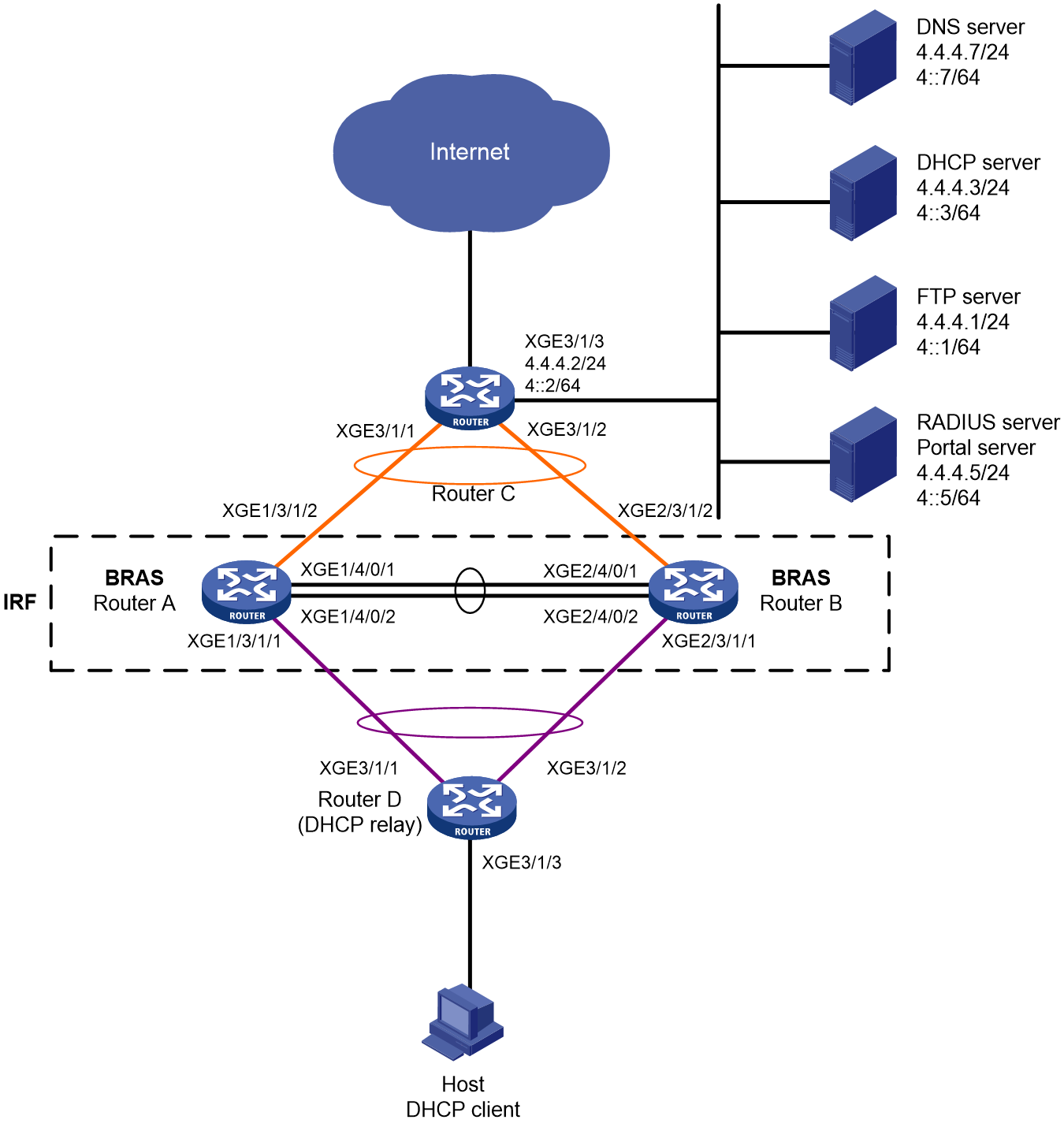
Table 23 IP address plan table
|
Device |
Interface |
IP addresses |
Device |
Interface |
IP addresses |
|
DNS server |
N/A |
4.4.4.7/24 4::7/64 |
IRF (BRAS) |
RAGG1 |
200.1.1.1/24 200::1/64 |
|
DHCP server |
N/A |
4.4.4.3/24 4::3/64 |
|
RAGG1023 |
100.1.1.1/24 100::1/64 |
|
FTP server |
N/A |
4.4.4.1/24 4::1/64 |
|
XGE1/3/1/1 |
N/A |
|
RADIUS server & portal server |
|
4.4.4.5/24 4::5/64 |
|
XGE2/3/1/1 |
N/A |
|
Router C |
RAGG1023 |
100.1.1.2/24 100::2/64 |
|
XGE1/3/1/2 |
N/A |
|
|
XGE 3/1/1 |
N/A |
|
XGE2/3/1/2 |
N/A |
|
|
XGE 3/1/2 |
N/A |
|
LoopBack1 |
80.1.1.1/32 80::1/128 |
|
|
XGE 3/1/3 |
4.4.4.2/24 4::2/64 |
|
|
|
|
Router D |
RAGG1 |
200.1.1.2/24 200::2/64 |
|
|
|
|
|
XGE 3/1/1 |
N/A |
|
|
|
|
|
XGE 3/1/2 |
N/A |
|
|
|
|
|
XGE 3/1/3 |
192.168.0.1/24 192::1/64 |
|
|
|
Analysis
· To prevent single point failures of member devices from affecting service forwarding, configure cross-chassis aggregation ports for service forwarding in the IRF fabric.
· To minimize the impact of IRF split on the services, configure LACP MAD detection in the IRF fabric. LACP MAD detection only needs to be configured in one aggregate group, and does not need to be configured in other aggregate groups. The intermediate device used for LACP MAD detection must be an H3C device and the software version used must be able to identify and process LACPDU protocol packets carrying ActiveID values. In this example, Router D is used as the intermediate device for LACP MAD detection.
· To ensure user bandwidth requirements, rate limiting is performed through authorized CAR.
· The traffic in the IPoE Web preauthentication domain is processed by using the following classes and traffic behaviors:
¡ The traffic class matching the DNS server and in the preauthentication domain user group corresponds to the filter permit traffic behavior.
¡ The traffic class matching the portal server and in the preauthentication domain user group corresponds to the filter permit traffic behavior.
¡ The traffic class matching the internal network server and in the preauthentication domain user group corresponds to the filter permit traffic behavior.
¡ The traffic class matching HTTP and in the preauthentication domain user group corresponds to the redirect http-to-cpu traffic behavior.
¡ The traffic class matching HTTPS and in the preauthentication domain user group corresponds to the redirect https-to-cpu traffic behavior.
¡ The traffic class matching IP and in the preauthentication domain user group corresponds to the redirect cpu traffic behavior. (Required only for transparent authentication.)
¡ The traffic class matching IP and in the preauthentication domain user group corresponds to the filter deny traffic behavior.
· Outbound traffic in the IPoE Web preauthentication domain is processed by using the following classes and traffic behaviors:
¡ The traffic class matching the DNS server and in the preauthentication domain user group corresponds to the filter permit traffic behavior.
¡ The traffic class matching the portal server and in the preauthentication domain user group corresponds to the filter permit traffic behavior.
¡ The traffic class matching the internal network server and in the preauthentication domain user group corresponds to the filter permit traffic behavior.
¡ The traffic class matching IP and in the preauthentication domain user group corresponds to the filter deny traffic behavior.
Restrictions and guidelines
To avoid port conflict, make sure the internal listening port number is not a well-known protocol port number, and it is not used by any other TCP-based services. To display TCP port numbers that have been used by other services, use the display tcp command.
This configuration uses DHCPv4 to assign IPv4 addresses to endpoints, and uses DHCPv6 to assign IPv6 addresses to endpoints, implementing single authentication for dual stacks. Android phones might be unable to obtain IPv6 addresses through this configuration.
On the level-1 DHCP relay agent (Router D):
· For users to implement single authentication for dual stacks, configure support for adding Option 79 on the DHCPv6 relay agent and configure Option 79 to be trusted on the BRAS device.
· Specify the DHCP server IP address as the IP address of the user onboarding interface on the BRAS device.
· If the interface is configured with an IPv6 unicast address, to avoid the endpoint from using temporary IPv6 address for authentication that can cause authentication failure, disable the user onboarding interface from advertising the prefix to avoid generating a temporary address (with the ipv6 nd ra prefix 192::/64 no-advertise command).
On the level-2 DHCP relay agent (BRAS device):
· Specify the DHCP server IP address as the IP address of the real DHCP server.
· Because the BRAS device serves as a level-2 DHCP relay agent between the level-1 DHCP relay agent and the DHCP server, enable non-first-hop DHCP relay agent on the user onboarding interface (Route-Aggregation1) on the BRAS device and the network-facing interface on the BRAS device used to connect to the DHCP server (Route-Aggregation1023). You only need to configure the dhcp relay non-first-hop enable command, and do not need to configure the ipv6 dhcp relay non-first-hop enable command.
· Disable online detection for IPv4 and IPv6 protocol stack users with the undo ip subscriber user-detect ip and undo ip subscriber user-detect ipv6 commands.
· Prevent users from going online due to interface failure with the user-policy interface-down online command.
DHCP flood attack prevention is not allowed to be enabled for user access interfaces on BRAS devices.
Procedures
Configuring IP addresses and routes
# Configure IPv4 address 4.4.4.2/24 and IPv6 address 4::2/64 for Ten-GigabitEthernet 3/1/3 on Router C.
<RouterC> system-view
[RouterC] interface ten-gigabitethernet 3/1/3
[RouterC-Ten-GigabitEthernet3/1/3] ip address 4.4.4.2 24
[RouterC-Ten-GigabitEthernet3/1/3] ipv6 address 4::2 64
[RouterC-Ten-GigabitEthernet3/1/3] quit
Configure static routes on Router C to the user end.
[RouterC] ip route-static 192.168.0.0 24 100.1.1.1
[RouterC] ipv6 route-static 192:: 64 100::1
Configuring DNS server settings
You need to set up the DNS server correctly, so that the server can resolve the IPv4 URL or IPv6 URL corresponding to the web authentication pages (http://www.ipv4.web.com and http://www.ipv6.web.com in this example) based on the protocol stack type of the dual-stack IPoE user who comes online first.
|
|
NOTE: This section takes Windows Server 2016 as an example to illustrate basic DNS server configuration. |
1. Install the DNS component.
a. Log in to the server, click the Windows button, and select server manager.
b. Click the add roles and features button to configure DNS.
c. On the before you begin step page, click Next.
d. On the installation type step page, keep the default settings (role-based or feature-based installation) and click Next.
e. On the server selection step page, keep the default settings (select server from server pool) and click Next.
f. On the select server roles step page, select DNS server. On the add roles and features wizard page that opens, click the add features button, and then click Next.
g. On the select function step page, keep the default settings and click Next.
h. On the DNS server step page, click Next.
i. Click Install on the confirmation step page and wait for the installation to complete.
j. On the results step page, click Close to complete the installation of the DNS component.
2. Create forward zone (IPv4)
a. On the server manager page, click Tools and select DNS.
b. On the DNS manager page, right-click forward zone and create a new zone.
c. On the new zone creation wizard page, click Next.
d. On the region type page, select primary zone and click Next.
e. On the zone name page, enter zone name ipv4.web.com.
f. On the zone file page, keep the default settings and click Next.
g. On the dynamic update page, specify not to allow dynamic updates and click Next.
h. Click Finish on the new zone wizard page.
i. On the DNS manager page, click forward zones, right-click ipv4.web.com, and create a new host
j. On the create host page, enter host name www, enter IP address 4.4.4.7, and click the add host button to set up the forward zone.
3. Set up the reverse zone (IPv4)
a. On the DNS manager page, right-click reverse zones and select to create a new zone.
b. On the new zone creation wizard page, click Next.
c. On the region type page, select primary zone and click Next.
d. On the reverse zone name page, select IPv4 reverse zone (4), and click Next.
e. On the reverse zone name page, enter the network ID 4.4.4 and click Next.
f. On the zone file page, keep the default settings and click Next.
g. On the dynamic update page, select Do not allow dynamic updates and click Next.
h. Click Finish on the new zone wizard page.
i. On the DNS manager page, click reverse zones, right-click and select 4.4.4.in-addr.arpa.dns, and click the new pointer button.
j. On the create new resource record page, enter host IP address 4.4.4.7, enter host name www.ipv4.web.com, and click OK to set up the reverse zone.
4. Set up the forward zone (IPv6)
a. On the server manager page, click Tools and select DNS.
b. On the DNS manager page, right-click forward zone and create a new zone.
c. On the new zone creation wizard page, click Next.
d. On the region type page, select primary zone and click Next.
e. On the region name page, enter the region name ipv6.web.com.
f. On the zone file page, keep the default settings and click Next.
g. On the dynamic update page, specify not to allow dynamic updates and click Next.
h. Click Finish on the new zone wizard page.
i. On the DNS manager page, click forward zones, right-click ipv6.web.com, and click the create host button.
j. On the new host page, enter host name www, enter IP address 4::7, and click the add host button to set up the forward zone.
5. Set up the reverse zone (IPv6)
a. On the DNS manager page, right-click reverse zones and create a new zone.
b. On the new zone creation wizard page, click Next.
c. On the region type page, select Primary Region and click Next.
d. On the reverse zone name page, select IPv6 reverse zone (6) and click Next.
e. On the reverse zone name page, enter network ID 4000:0000:0000:0000::/64, and click Next.
f. On the zone file page, keep the default settings and click Next.
g. On the dynamic update page, specify not to allow dynamic updates and click Next.
h. Click Finish on the new zone wizard page.
i. On the DNS manager page, click reverse zones, right-click and select 0.0.0.0.0.0.0.0.0.0.0.0.0.0.0.4.in-addr.arpa.dns, and then click the create pointer button.
j. On the new resource record page, enter host IP address, 4000.0000.0000.0000.0000.0000.0000.0007, enter host name www.ipv6.web.com, and click OK to set up the reverse zone.
Configuring the level-1 DHCP relay agent
1. Configure the DHCP relay agent feature
# Enable DHCP globally.
[RouterD] dhcp enable
# Enter the view of interface Ten-GigabitEthernet 3/1/3 connected to the user end.
[RouterD] interface ten-gigabitethernet 3/1/3
# Enable the DHCP relay agent on the interface, and specify the DHCP server address as the IP address of the user onboarding interface on the BRAS device.
[RouterD-Ten-GigabitEthernet3/1/3] dhcp select relay
[RouterD-Ten-GigabitEthernet3/1/3] dhcp relay server-address 200.1.1.1
# Enable the DHCPv6 relay agent on the interface, and specify the DHCPv6 server address as the IP address of the user onboarding interface on the BRAS device.
[RouterD-Ten-GigabitEthernet3/1/3] ipv6 dhcp select relay
[RouterD-Ten-GigabitEthernet3/1/3] ipv6 dhcp relay server-address 200::1
# Disable RA message suppression, and disable the device from advertising the prefix of the interface to avoid generating a temporary address.
[RouterD-Ten-GigabitEthernet3/1/3] undo ipv6 nd ra halt
[RouterD-Ten-GigabitEthernet3/1/3] ipv6 nd ra prefix 192::/64 no-advertise
# Set the M flag to 1, that is, hosts acquire IPv6 addresses through the DHCPv6 server. Set the O flag to 1, that is, hosts use the DHCPv6 server to acquire information other than IPv6 addresses.
[RouterD-Ten-GigabitEthernet3/1/3] ipv6 nd autoconfig managed-address-flag
[RouterD-Ten-GigabitEthernet3/1/3] ipv6 nd autoconfig other-flag
# Enable the DHCPv6 relay agent to support Option 79.
[RouterD-Ten-GigabitEthernet3/1/3] ipv6 dhcp relay client-link-address enable
[RouterD-Ten-GigabitEthernet3/1/3] quit
Configure default routes from the DHCP relay agent to the user end. (This example uses default routes for illustration. You can configure other routes as needed in your network.)
[RouterD] ip route-static 0.0.0.0 0 200.1.1.1
[RouterD] ipv6 route-static :: 0 200::1
2. Configure the attack prevention feature
¡ Configure source MAC-based ARP attack detection
# Enable source MAC-based ARP attack detection and specify the filter handling method.
[RouterD] arp source-mac filter
# Set the check interval to 5 seconds for source MAC-based ARP attack detection.
[RouterD] arp source-mac check-interval 5
# Set the threshold to 30 for source MAC-based ARP attack detection.
[RouterD] arp source-mac threshold 30
# Set the aging time to 300 seconds for source MAC-based ARP attack detection entries.
[RouterD] arp source-mac aging-time 300
¡ Configure source MAC-based ND attack detection
# Enable source MAC-based ND attack detection and specify the filter handling method.
[RouterD] ipv6 nd source-mac filter
# Set the check interval to 5 seconds for source MAC-based ND attack detection.
[RouterD] ipv6 nd source-mac check-interval 5
# Set the threshold to 30 for source MAC-based ND attack detection.
[RouterD] ipv6 nd source-mac threshold 30
# Set the aging time to 300 seconds for source MAC-based ND attack detection entries.
[RouterD] ipv6 nd source-mac aging-time 300
¡ Enable DHCP flood attack protection.
# Enable DHCP flood attack protection on Ten-GigabitEthernet 3/1/3.
[RouterD] interface ten-gigabitethernet 3/1/3
[RouterD-Ten-GigabitEthernet3/1/3] dhcp flood-protection enable
[RouterD–Ten-GigabitEthernet3/1/3] quit
# Configure the device to allow a maximum of 30 DHCP packets per 10000 milliseconds from each DHCP client.
[RouterD] dhcp flood-protection threshold 30 10000
# Set the aging timer to 300 seconds for DHCP flood attack detection entries.
[RouterD] dhcp flood-protection aging-time 300
¡ Configure DHCPv6 flood attack prevention
# Enable DHCPv6 flood attack protection on Ten-GigabitEthernet 3/1/3.
[RouterD] interface ten-gigabitEthernet 3/1/3
[RouterD-Ten-GigabitEthernet3/1/3] ipv6 dhcp flood-protection enable
[RouterD-Ten-GigabitEthernet3/1/3] quit
# Configure the device to allow a maximum of 30 DHCPv6 packets per 10000 milliseconds from each DHCPv6 client.
[RouterD] ipv6 dhcp flood-protection threshold 30 10000
# Set the aging timer to 300 seconds for DHCPv6 flood attack detection entries.
[RouterD] ipv6 dhcp flood-protection aging-time 300
¡ Enable ICMP/ICMPv6 fast reply.
[RouterD] ip icmp fast-reply enable
[RouterD] ipv6 icmpv6 fast-reply enable
¡ Enable TCP SYN flood attack prevention.
# Enable flow-based TCP SYN flood attack prevention.
[RouterD] tcp anti-syn-flood flow-based enable
# Set the check interval to 20 seconds for flow-based TCP SYN flood attack prevention.
[RouterD] tcp anti-syn-flood flow-based check-interval 20
# Set the threshold to 2000 for triggering flow-based TCP SYN flood attack prevention.
[RouterD] tcp anti-syn-flood flow-based threshold 2000
# Set the flow-based TCP SYN flood attack prevention duration to 5 minutes.
[RouterD] tcp anti-syn-flood flow-based duration 5
3. Configure DHCP server settings
a. Configure a DHCPv4 address pool
# Enable DHCP.
<DHCP> system-view
[DHCP] dhcp enable
# Enable the DHCP server to return a DHCP-NAK message if the client notions of their IP addresses are incorrect.
[DHCP] dhcp server request-ip-address check
# Create a common IP pool named pool1 and enter its view.
[DHCP] ip pool pool1
# Specify subnet 192.168.0.0/24 and DNS server address 4.4.4.7 for dynamic allocation in the DHCP address pool.
[DHCP-ip-pool-pool1] network 192.168.0.0 24
[DHCP-ip-pool-pool1] dns-list 4.4.4.7
# Specify gateway address 192.168.0.1 to be allocated to users.
[DHCP-ip-pool-pool1] gateway-list 192.168.0.1
# Exclude IP address 192.168.0.1 from dynamic allocation in the DHCP address pool.
[DHCP-ip-pool-pool1] forbidden-ip 192.168.0.1
[DHCP-ip-pool-pool1] quit
# Configure the default route. (This example uses a default route for illustration. You can configure other routes as needed in your network.)
[DHCP] ip route-static 0.0.0.0 0 4.4.4.2
b. Configure a DHCPv6 address pool
# Create a DHCPv6 address pool named pool2 and enter its view.
[DHCP] ipv6 pool pool2
# Specify subnet 192::/64 and DNS server address 4::7 for dynamic allocation in the DHCPv6 address pool.
[DHCP-ipv6-pool-pool2] network 192::/64
[DHCP-ipv6-pool-pool2] dns-server 4::7
[DHCP-ipv6-pool-pool2] quit
# Set 192::1 as a forbidden address.
[DHCP] ipv6 dhcp server forbidden-address 192::1
# Enable the DHCPv6 server on Ten-GigabitEthernet 3/1/1.
[DHCP] interface ten-gigabitethernet 3/1/1
[DHCP-Ten-GigabitEthernet3/1/1] ipv6 dhcp select server
[DHCP-Ten-GigabitEthernet3/1/1] quit
# Configure the default route. (This example uses a default route for illustration. You can configure other routes as needed in your network.)
[DHCP] ipv6 route-static :: 0 4::2
Configure RADIUS and portal servers
|
|
NOTE: This section takes Srun 4.0.9 server as an example to illustrate basic RADIUS server and portal server configuration. |
1. Enter http://4.4.4.5:8081 in the browser and log in to the server to add an access device.
Click device management on the navigation bar, select the add device tab, and click Add.
¡ Set the device name to BRAS.
¡ Set the NAS IP address to the IP address of LoopBack1 interface (80.1.1.1) on the BRAS device.
¡ Set our IP to 4.4.4.5.
¡ Specify the NAS type as Huawei, H3C, and Srun gateway.
¡ Set the DM port number to 3799.
¡ Set the RADIUS key to 123456.
¡ Specify not to discard traffic.
¡ Select portal protocol H3C or Huawei (H3C v1.2).
¡ Set the portal key to 123456.
# Configure RADIUS trust settings. Click the RADIUS tab on the navigation bar and select the RADIUS trust settings link to enter the RADIUS trust settings page. Click the Generate button in the top right corner repeatedly until the generation is successful. Then, restart the RADIUS process for Srun.
Select the RADIUS service settings tab and specify the username verification as with domain name.
2. Enter https://4.4.4.5:8080 in the browser and log in to the server to add a user.
Select the user management/add user tab and click Add.
¡ Add user user1 with account user1 and password pass.
3. To deploy control policies and product policy configuration, see the Srun product manual.
Setting up an IRF fabric
1. Set up an IRF fabric with Router A and Router B
# Assign member ID 1 to Router A, create IRF port 2, and bind it to physical ports Ten-GigabitEthernet 4/0/1 and Ten-GigabitEthernet4/0/2.
<RouterA> system-view
[RouterA] irf member 1 priority 2
[RouterA] interface ten-gigabitethernet 4/0/1
[RouterA-Ten-GigabitEthernet4/0/1] port link-mode bridge
[RouterA-Ten-GigabitEthernet4/0/1] quit
[RouterA] interface ten-gigabitethernet 4/0/2
[RouterA-Ten-GigabitEthernet4/0/2] port link-mode bridge
[RouterA-Ten-GigabitEthernet4/0/2] quit
[RouterA] irf-port 2
[RouterA-irf-port2] port group interface ten-gigabitethernet 4/0/1
[RouterA-irf-port2] port group interface ten-gigabitethernet 4/0/2
[RouterA-irf-port2] quit
# Save the current configuration to the configuration file for next startup.
[RouterA] quit
<RouterA> save
# Enable IRF mode.
<RouterA> system-view
[RouterA] chassis convert mode irf
The device will switch to IRF mode and reboot. Continue?[Y/N]:y
You are recommended to save the current running configuration and specify the configuration file for the next startup. Now save the running configuration to the next-startup configuration file? [Y/N]:y
Please input the file name(*.cfg)[cfa0:/test.cfg]
(To leave the existing filename unchanged, press the enter key):
cfa0:/test.cfg exists, overwrite? [Y/N]:y
Validating file. Please wait...
Saved the current configuration to mainboard device successfully.
Do you want to convert the content of the next startup configuration file cfa0:/test.cfg to make it available in IRF mode? [Y/N]:y
Now rebooting, please wait...
Upon restart, Router A forms an IRF fabric with only one member device.
# Assign member ID 2 to Router B, create IRF port 1, and bind it to physical ports Ten-GigabitEthernet 4/0/1 and Ten-GigabitEthernet 4/0/2.
<RouterB> system-view
[RouterB] irf member 2 priority 1
[RouterB] interface ten-gigabitethernet 4/0/1
[RouterB-Ten-GigabitEthernet4/0/1] port link-mode bridge
[RouterB-Ten-GigabitEthernet4/0/1] quit
[RouterB] interface ten-gigabitethernet 4/0/2
[RouterB-Ten-GigabitEthernet4/0/2] port link-mode bridge
[RouterB-Ten-GigabitEthernet4/0/2] quit
[RouterB] irf-port 1
[RouterB-irf-port1] port group interface ten-gigabitethernet 4/0/1
[RouterB-irf-port1] port group interface ten-gigabitethernet 4/0/2
[RouterB-irf-port1] quit
# Save the current configuration to the configuration file for next startup.
[RouterB] quit
<RouterB> save
# Enable IRF mode.
<RouterB> system-view
[RouterB] chassis convert mode irf
The device will switch to IRF mode and reboot. Continue?[Y/N]:y
You are recommended to save the current running configuration and specify the configuration file for the next startup. Now save the running configuration to the next-startup configuration file? [Y/N]:y
Please input the file name(*.cfg)[cfa0:/test.cfg]
(To leave the existing filename unchanged, press the enter key):
cfa0:/test.cfg exists, overwrite? [Y/N]:y
Validating file. Please wait...
Saved the current configuration to mainboard device successfully.
Do you want to convert the content of the next startup configuration file cfa0:/test.cfg to make it available in IRF mode? [Y/N]:y
Now rebooting, please wait...
Upon restart, Router B form an IRF fabric with Router A.
2. Configure downlink services for the IRF fabric
a. Configure LACP MAD
|
|
NOTE: In this example, Router A serves as the master in the IRF fabric and as the BRAS in IPoE. To facilitate understanding, Router A is described as IRF in the IRF section and described as BRAS in the IPoE section in the subsequent configuration steps. |
Once the IRF fabric is formed, you can start configuring various service modules. After the IRF fabric is set up, you can log in to any member device to perform configurations. The default device name is the name of the master device (Router A in this example).
# Create dynamic aggregation group 1 connected to Router D, and enable LACP MAD detection.
<IRF> system-view
[IRF] interface route-aggregation 1
[IRF-Route-Aggregation1] link-aggregation mode dynamic
[IRF-Route-Aggregation1] mad enable
You need to assign a domain ID (range: 0-4294967295)
[Current domain is: 0]:
The assigned domain ID is: 0
MAD LACP only enable on dynamic aggregation interface.
[IRF-Route-Aggregation1] quit
# Assign the ports connected to Router D to aggregation group 1.
[IRF] interface ten-gigabitethernet 1/3/1/1
[IRF-Ten-GigabitEthernet1/3/1/1] port link-aggregation group 1
[IRF-Ten-GigabitEthernet1/3/1/1] quit
[IRF] interface ten-gigabitethernet 2/3/1/1
[IRF-Ten-GigabitEthernet2/3/1/1] port link-aggregation group 1
[IRF-Ten-GigabitEthernet2/3/1/1] quit
b. Configure Router D
# Create dynamic aggregation group 1 connected to the IRF fabric. The aggregation group is also used for LACP MAD detection of the IRF fabric.
<RouterD> system-view
[RouterD] interface route-aggregation 1
[RouterD-Route-Aggregation1] link-aggregation mode dynamic
[RouterD-Route-Aggregation1] quit
# Assign the ports connected to the IRF fabric to aggregation group 1.
[RouterD] interface ten-gigabitethernet 3/1/1
[RouterD-Ten-GigabitEthernet3/1/1] port link-aggregation group 1
[RouterD-Ten-GigabitEthernet3/1/1] quit
[RouterD] interface ten-gigabitethernet 3/1/2
[RouterD-Ten-GigabitEthernet3/1/2] port link-aggregation group 1
[RouterD-Ten-GigabitEthernet3/1/2] quit
3. Configuring uplink services for the IRF fabric
a. Configure link aggregation settings for the IRF fabric
# Create dynamic aggregation group 1023 connected to egress router Router C, and configure its IPv4 address as 100.1.1.1/24 and IPv6 address as 100::1/64.
[IRF] interface route-aggregation 1023
[IRF-Route-Aggregation1023] link-aggregation mode dynamic
[IRF-Route-Aggregation1023] ip address 100.1.1.1 24
[IRF-Route-Aggregation1023] ipv6 address 100::1 64
[IRF-Route-Aggregation1023] quit
# Assign the ports connected to Router C to aggregation group 1023.
[IRF] interface ten-gigabitethernet 1/3/1/2
[IRF-Ten-GigabitEthernet1/3/1/2] port link-aggregation group 1023
[IRF-Ten-GigabitEthernet1/3/1/2] quit
[IRF] interface ten-gigabitethernet 2/3/1/2
[IRF-Ten-GigabitEthernet2/3/1/2] port link-aggregation group 1023
[IRF-Ten-GigabitEthernet2/3/1/2] quit
# Configure the static routes to Router C (for accessing the server and Internet).
[IRF] ip route-static 0.0.0.0 0 100.1.1.2
[IRF] ipv6 route-static :: 0 100::2
b. Configure Router C
|
|
NOTE: This example describes only the connection to the IRF fabric for the egress router configuration, and does not describe the routing protocol used for the external network. |
# Create dynamic aggregation group 1023 connected to the IRF fabric, and configure its IPv4 address as 100.1.1.2/24 and IPv6 address as 100::2/64.
<RouterC> system-view
[RouterC] interface route-aggregation 1023
[RouterC-Route-Aggregation1023] link-aggregation mode dynamic
[RouterC-Route-Aggregation1023] ip address 100.1.1.2 24
[RouterC-Route-Aggregation1023] ipv6 address 100::2 64
[RouterC-Route-Aggregation1023] quit
# Assign the ports connected to the IRF fabric to aggregation group 1023.
[RouterC] interface ten-gigabitethernet 3/1/1
[RouterC-Ten-GigabitEthernet3/1/1] port link-aggregation group 1023
[RouterC-Ten-GigabitEthernet3/1/1] quit
[RouterC] interface ten-gigabitethernet 3/1/2
[RouterC-Ten-GigabitEthernet3/1/2] port link-aggregation group 1023
[RouterC-Ten-GigabitEthernet3/1/2] quit
Configuring BRAS
1. Configure the level-2 DHCP relay agent
# Enable DHCP.
[BRAS] dhcp enable
# Enter the view of interface Route-Aggregation 1.
[BRAS] interface route-aggregation 1
# Enable the DHCPv4 relay agent on the interface, and specify the DHCP server on the DHCP relay agent.
[BRAS–Route-Aggregation1] dhcp select relay
[BRAS–Route-Aggregation1] dhcp relay server-address 4.4.4.3
# Enable the DHCPv6 relay agent on the interface, and specify the DHCPv6 server on the DHCPv6 relay agent.
[BRAS–Route-Aggregation1] ipv6 dhcp select relay
[BRAS–Route-Aggregation1] ipv6 dhcp relay server-address 4::3
# Disable the RA message suppression.
[BRAS–Route-Aggregation1] undo ipv6 nd ra halt
# Set the M flag to 1, that is, hosts acquire IPv6 addresses through the DHCPv6 server. Set the O flag to 1, that is, hosts use the DHCPv6 server to acquire information other than IPv6 addresses.
[BRAS–Route-Aggregation1] ipv6 nd autoconfig managed-address-flag
[BRAS–Route-Aggregation1] ipv6 nd autoconfig other-flag
# Enable the non-first-hop DHCP relay agent feature.
[BRAS–Route-Aggregation1] dhcp relay non-first-hop enable
[BRAS–Route-Aggregation1] quit
# Enter the view of interface Route-Aggregation 1023.
[BRAS] interface route-aggregation 1023
# Enable the non-first-hop DHCP relay agent feature.
[BRAS–Route-Aggregation1023] dhcp relay non-first-hop enable
[BRAS–Route-Aggregation1023] quit
# Configure a static route to specify next hop 200.1.1.2 for DHCPv4 reply packets destined to subnet 192.168.0.0/24.
[BRAS] ip route-static 192.168.0.0 24 200.1.1.2
# Configure an IPv6 static route to specify next hop 200::2 for DHCPv6 reply packets destined to subnet 192::/64.
[BRAS] ipv6 route-static 192:: 64 200::2
2. Configure portal authentication servers
# Create IPv4 portal authentication server named newpt1, specify its IP address as 4.4.4.5, and specify the key as 123456 in plaintext form.
[BRAS] portal server newpt1
[BRAS-portal-server-newpt1] ip 4.4.4.5 key simple 123456
[BRAS-portal-server-newpt1] quit
# Create IPv6 portal authentication server named newpt2, specify its IPv6 address as 4::5, and specify the key as 123456 in plaintext form.
[BRAS] portal server newpt2
[BRAS-portal-server-newpt2] ipv6 4::5 key simple 123456
[BRAS-portal-server-newpt2] quit
3. Specify the HTTPS redirect listening port number
# Specify the HTTPS redirect listening port number. (To avoid port conflict, do not specify a TCP port number used by any other service. To display TCP port numbers that have been used by services, use the display tcp command.)
[BRAS] http-redirect https-port 11111
4. Configure the device to get user access information from ARP entries
# Configure the device to get user access information from ARP entries.
[BRAS] portal access-info trust arp
[BRAS] portal access-info trust nd
5. Create a local user group
# Create a preauthentication domain user group named pre.
[BRAS] user-group pre
New user group added.
[BRAS-ugroup-pre] quit
6. Configure QoS
a. Configure ACL rules for preauthentication domain users.
# Configure rules for IPv4 and IPv6 advanced ACL dns_permit to match packets whose destination address is the DNS server address in user group pre.
[BRAS] acl advanced name dns_permit
[BRAS-acl-ipv4-adv-dns_permit] rule 0 permit ip destination 4.4.4.7 0 user-group pre
[BRAS-acl-ipv4-adv-dns_permit] quit
[BRAS] acl ipv6 advanced name dns_permit
[BRAS-acl-ipv6-adv-dns_permit] rule 0 permit ipv6 destination 4::7 128 user-group pre
[BRAS-acl-ipv6-adv-dns_permit] quit
# Configure rules for IPv4 and IPv6 advanced ACL web_permit to match packets whose destination address is the portal server address in user group pre.
[BRAS] acl advanced name web_permit
[BRAS-acl-ipv4-adv-web_permit] rule 0 permit ip destination 4.4.4.5 0 user-group pre
[BRAS-acl-ipv4-adv-web_permit] quit
[BRAS] acl ipv6 advanced name web_permit
[BRAS-acl-ipv6-adv-web_permit] rule 0 permit ipv6 destination 4::5 128 user-group pre
[BRAS-acl-ipv6-adv-web_permit] quit
# Configure rules for IPv4 and IPv6 advanced ACL neiwang to match packets whose destination address is the internal network server address in user group pre.
[BRAS] acl advanced name neiwang
[BRAS-acl-ipv4-adv-neiwang] rule 0 permit ip destination 4.4.4.1 0 user-group pre
[BRAS-acl-ipv4-adv-neiwang] quit
[BRAS] acl ipv6 advanced name neiwang
[BRAS-acl-ipv6-adv-neiwang] rule 0 permit ipv6 destination 4::1 128 user-group pre
[BRAS-acl-ipv6-adv-neiwang] quit
# Create rules for IPv4 and IPv6 advanced ACL web_http to match TCP packets (HTTP packets) with destination port 80 for the users in user group pre.
[BRAS] acl advanced name web_http
[BRAS-acl-ipv4-adv-web_http] rule 0 permit tcp destination-port eq www user-group pre
[BRAS-acl-ipv4-adv-web_http] quit
[BRAS] acl ipv6 advanced name web_http
[BRAS-acl-ipv6-adv-web_http] rule 0 permit tcp destination-port eq www user-group pre
[BRAS-acl-ipv6-adv-web_http] quit
# Create rules for IPv4 and IPv6 advanced ACL web_https to match TCP packets (HTTPS packets) with destination port 443 for the users in user group pre.
[BRAS] acl advanced name web_https
[BRAS-acl-ipv4-adv-web_https] rule 0 permit tcp destination-port eq 443 user-group pre
[BRAS-acl-ipv4-adv-web_https] quit
[BRAS] acl ipv6 advanced name web_https
[BRAS-acl-ipv6-adv-web_https] rule 0 permit tcp destination-port eq 443 user-group pre
[BRAS-acl-ipv6-adv-web_https] quit
# Create rules for IPv4 and IPv6 advanced ACL ip to match IP packets for the users in user group pre.
[BRAS] acl advanced name ip
[BRAS-acl-ipv4-adv-ip] rule 0 permit ip user-group pre
[BRAS-acl-ipv4-adv-ip] quit
[BRAS] acl ipv6 advanced name ip
[BRAS-acl-ipv6-adv-ip] rule 0 permit ipv6 user-group pre
[BRAS-acl-ipv6-adv-ip] quit
# Configure rules for IPv4 and IPv6 advanced ACL neiwang_out to match packets whose source address is the internal network server address in user group pre.
[BRAS] acl advanced name neiwang_out
[BRAS-acl-ipv4-adv-neiwang_out] rule 0 permit ip source 4.4.4.1 0 user-group pre
[BRAS-acl-ipv4-adv-neiwang_out] quit
[BRAS] acl ipv6 advanced name neiwang_out
[BRAS-acl-ipv6-adv-neiwang_out] rule 0 permit ipv6 source 4::1 128 user-group pre
[BRAS-acl-ipv6-adv-neiwang_out] quit
# Configure rules for IPv4 and IPv6 advanced ACL web_out to match packets whose source address is the portal server address in user group pre.
[BRAS] acl advanced name web_out
[BRAS-acl-ipv4-adv-web_out] rule 0 permit ip source 4.4.4.5 0 user-group pre
[BRAS-acl-ipv4-adv-web_out] quit
[BRAS] acl ipv6 advanced name web_out
[BRAS-acl-ipv6-adv-web_out] rule 0 permit ipv6 source 4::5 128 user-group pre
[BRAS-acl-ipv6-adv-web_out] quit
# Configure rules for IPv4 and IPv6 advanced ACL dns_out to match packets whose source address is the DNS server address in user group pre.
[BRAS] acl advanced name dns_out
[BRAS-acl-ipv4-adv-dns_out] rule 0 permit ip source 4.4.4.7 0 user-group pre
[BRAS-acl-ipv4-adv-dns_out] quit
[BRAS] acl ipv6 advanced name dns_out
[BRAS-acl-ipv6-adv-dns_out] rule 0 permit ipv6 source 4::7 128 user-group pre
[BRAS-acl-ipv6-adv-dns_out] quit
b. Configure traffic classes for the preauthentication domain.
# Configure traffic class dns_permit to match ACL dns_permit.
[BRAS] traffic classifier dns_permit operator or
[BRAS-classifier-dns_permit] if-match acl name dns_permit
[BRAS-classifier-dns_permit] if-match acl ipv6 name dns_permit
[BRAS-classifier-dns_permit] quit
# Configure traffic class web_permit to match ACL web_permit.
[BRAS] traffic classifier web_permit operator or
[BRAS-classifier-web_permit] if-match acl name web_permit
[BRAS-classifier-web_permit] if-match acl ipv6 name web_permit
[BRAS-classifier-web_permit] quit
# Configure traffic class neiwang to match ACL neiwang.
[BRAS] traffic classifier neiwang operator or
[BRAS-classifier-neiwang] if-match acl name neiwang
[BRAS-classifier-neiwang] if-match acl ipv6 name neiwang
[BRAS-classifier-neiwang] quit
# Configure traffic class web_http to match ACL web_http.
[BRAS] traffic classifier web_http operator or
[BRAS-classifier-web_http] if-match acl name web_http
[BRAS-classifier-web_http] if-match acl ipv6 name web_http
[BRAS-classifier-web_http] quit
# Configure traffic class web_https to match ACL web_https.
[BRAS] traffic classifier web_https operator or
[BRAS-classifier-web_https] if-match acl name web_https
[BRAS-classifier-web_https] if-match acl ipv6 name web_https
[BRAS-classifier-web_https] quit
# Configure traffic class web_deny to match ACL ip.
[BRAS] traffic classifier web_deny operator or
[BRAS-classifier-web_deny] if-match acl name ip
[BRAS-classifier-web_deny] if-match acl ipv6 name ip
[BRAS-classifier-web_deny] quit
# Configure traffic class neiwang_out to match ACL neiwang_out.
[BRAS] traffic classifier neiwang_out operator or
[BRAS-classifier-neiwang_out] if-match acl name neiwang_out
[BRAS-classifier-neiwang_out] if-match acl ipv6 name neiwang_out
[BRAS-classifier-neiwang_out] quit
# Configure traffic class web_out to match ACL web_out.
[BRAS] traffic classifier web_out operator or
[BRAS-classifier-web_out] if-match acl name web_out
[BRAS-classifier-web_out] if-match acl ipv6 name web_out
[BRAS-classifier-web_out] quit
# Configure traffic class dns_out to match ACL dns_out.
[BRAS] traffic classifier dns_out operator or
[BRAS-classifier-dns_out] if-match acl name dns_out
[BRAS-classifier-dns_out] if-match acl ipv6 name dns_out
[BRAS-classifier-dns_out] quit
c. Configure traffic behaviors
# Configure traffic behavior dns_permit to permit packets whose the destination address is the DNS server address in user group pre to pass through.
[BRAS] traffic behavior dns_permit
[BRAS-behavior-dns_permit] filter permit
[BRAS-behavior-dns_permit] free account
[BRAS-behavior-dns_permit] quit
# Configure traffic behavior web_permit to permit packets whose the destination address is the portal server address in user group pre to pass through.
[BRAS] traffic behavior web_permit
[BRAS-behavior-web_permit] filter permit
[BRAS-behavior-web_permit] free account
[BRAS-behavior-web_permit] quit
# Configure traffic behavior neiwang to permit packets whose the destination address is the internal network server address in user group pre to pass through.
[BRAS] traffic behavior neiwang
[BRAS-behavior-neiwang] filter permit
[BRAS-behavior-neiwang] free account
[BRAS-behavior-neiwang] quit
# Configure traffic behavior web_http to redirect TCP packets (HTTP packets) with destination port 80 for the users in user group pre to the CPU.
[BRAS] traffic behavior web_http
[BRAS-behavior-web_http] redirect http-to-cpu
[BRAS-behavior-web_http] quit
# Configure traffic behavior web_https to redirect TCP packets (HTTPS packets) with destination port 443 for the users in user group pre to the CPU.
[BRAS] traffic behavior web_https
[BRAS-behavior-web_https] redirect https-to-cpu
[BRAS-behavior-web_https] quit
# Configure traffic behavior web_deny to prohibit all IP packets in user group pre from passing through.
[BRAS] traffic behavior web_deny
[BRAS-behavior-web_deny] filter deny
[BRAS-behavior-web_deny] free account
[BRAS-behavior-web_deny] quit
# Configure traffic behavior neiwang_out to permit packets whose source address is the internal network server address in user group pre to pass through.
[BRAS] traffic behavior neiwang_out
[BRAS-behavior-neiwang_out] filter permit
[BRAS-behavior-neiwang_out] free account
[BRAS-behavior-neiwang_out] quit
# Configure traffic behavior web_out to permit packets whose source address is the portal server address in user group pre to pass through.
[BRAS] traffic behavior web_out
[BRAS-behavior-web_out] filter permit
[BRAS-behavior-web_out] free account
[BRAS-behavior-web_out] quit
# Configure traffic behavior dns_out to permit packets whose source address is the DNS server address in user group pre to pass through.
[BRAS] traffic behavior dns_out
[BRAS-behavior-dns_out] filter permit
[BRAS-behavior-dns_out] free account
[BRAS-behavior-dns_out] quit
d. Configure QoS policies
# Configure inbound QoS policy web.
[BRAS] qos policy web
# Associate traffic behaviors with traffic classes. For users in user group pre:
Permit packets whose destination address is the DNS server, portal server, and internal network address to pass through.
Redirect packets with destination port 80 (HTTP packets) or 443 (HTTPS packets) to the CPU.
Prohibit any other packets from passing through.
[BRAS-qospolicy-web] classifier dns_permit behavior dns_permit
[BRAS-qospolicy-web] classifier web_permit behavior web_permit
[BRAS-qospolicy-web] classifier neiwang behavior neiwang
[BRAS-qospolicy-web] classifier web_http behavior web_http
[BRAS-qospolicy-web] classifier web_https behavior web_https
[BRAS-qospolicy-web] classifier web_deny behavior web_deny
[BRAS-qospolicy-web] quit
# Configure outbound QoS policy out.
[BRAS] qos policy out
# Specify traffic behaviors for traffic classes: For user group pre, permit packets with the DNS, portal, or internal server address as the source address to pass through, and prohibit any other packets from passing through.
[BRAS-qospolicy-out] classifier dns_out behavior dns_out
[BRAS-qospolicy-out] classifier web_out behavior web_out
[BRAS-qospolicy-out] classifier neiwang_out behavior neiwang_out
[BRAS-qospolicy-out] classifier web_deny behavior web_deny
[BRAS-qospolicy-out] quit
e. Configure application policies
# Apply QoS policy web to received user traffic. (After applying the policy, you can execute the display qos policy global inbound command to examine whether the policy has taken effect.)
[BRAS] qos apply policy web global inbound
# Apply QoS policy out to sent online user traffic. (After applying the policy, you can execute the display qos policy global outbound command to examine whether the policy has taken effect.)
[BRAS] qos apply policy out global outbound
7. Configure RADIUS scheme.
# Create a RADIUS scheme named rs1 and enter its view.
[BRAS] radius scheme rs1
# Configure the primary authentication and accounting servers, and the keys for the servers to communicate.
[BRAS-radius-rs1] primary authentication 4.4.4.5
[BRAS-radius-rs1] primary accounting 4.4.4.5
[BRAS-radius-rs1] key authentication simple 123456
[BRAS-radius-rs1] key accounting simple 123456
# Specify that the ISP domain name should not be included in the username sent to the RADIUS server.
[BRAS-radius-rs1] user-name-format without-domain
# Specify IP address 80.1.1.1 as the NAS IPv4 address of RADIUS packets.
[BRAS-radius-rs1] nas-ip 80.1.1.1
[BRAS-radius-rs1] quit
# Enable the RADIUS DAS feature. Specify the DAC as 4.4.4.5. Set the shared key to 123456 in plaintext form for secure communication between the DAS and DAC. Make sure the plaintext passwords are consistent on the two authentication ends.
[BRAS] radius dynamic-author server
[BRAS-radius-da-server] client ip 4.4.4.5 key simple 123456
[BRAS-radius-da-server] quit
8. Configure the preauthentication domain and Web authentication domain
# Configure the authentication domain for IPoE users before authentication.
[BRAS] domain name dm1
[BRAS-isp-dm1] authentication ipoe none
[BRAS-isp-dm1] authorization ipoe none
[BRAS-isp-dm1] accounting ipoe none
# Configure the user group authorization attribute for the preauthentication domain.
[BRAS-isp-dm1] authorization-attribute user-group pre
# Configure the Web authentication page URLs.
[BRAS-isp-dm1] web-server url http://www.ipv4.web.com
[BRAS-isp-dm1] web-server ipv6-url http://www.ipv6.web.com
[BRAS-isp-dm1] quit
# Configure the authentication domain for IPoE users during Web authentication.
[BRAS] domain name dm2
[BRAS-isp-dm2] authentication ipoe radius-scheme rs1
[BRAS-isp-dm2] authorization ipoe radius-scheme rs1
[BRAS-isp-dm2] accounting ipoe radius-scheme rs1
[BRAS-isp-dm2] authorization-attribute car inbound cir 5120 outbound cir 5120
[BRAS-isp-dm2] quit
9. Configure IPoE
# Enable IPoE and configure the Layer 3 access mode for users.
[BRAS] interface route-aggregation 1
[BRAS–Route-Aggregation1] ip subscriber routed enable
# Configure the Web authentication method for IPoE users.
[BRAS–Route-Aggregation1] ip subscriber authentication-method web
The operation may cut all users on this interface. Continue?[Y/N]:y
# Specify ISP domain dm1 for preauthentication and ISP domain dm2 for Web authentication.
[BRAS–Route-Aggregation1] ip subscriber pre-auth domain dm1
[BRAS–Route-Aggregation1] ip subscriber web-auth domain dm2
# Configure DHCPv6 Option 79 as a trusted option.
[BRAS–Route-Aggregation1] ip subscriber trust option79
Enable unclassified-IPv4 and IPv6 packet initiation.
[BRAS–Route-Aggregation1] ip subscriber initiator unclassified-ip enable matching-user
[BRAS–Route-Aggregation1] ip subscriber initiator unclassified-ipv6 enable matching-user
# Disable online detection for IPv4 and IPv6 protocol stack users.
[BRAS–Route-Aggregation1] undo ip subscriber user-detect ip
[BRAS–Route-Aggregation1] undo ip subscriber user-detect ipv6
# Keep the users online and does not perform online detection on users after the interface goes down.
[BRAS–Route-Aggregation1] user-policy interface-down online no-user-detect
# (Optional.) Configure the DHCP server to use the fast-renew method for roaming clients.
[BRAS–Route-Aggregation1] dhcp session-mismatch action fast-renew
[BRAS–Route-Aggregation1] ipv6 dhcp session-mismatch action fast-renew
[BRAS–Route-Aggregation1] quit
10. Configure the attack prevention feature
¡ Configure source MAC-based ARP attack detection
# Enable source MAC-based ARP attack detection and specify the filter handling method.
[BRAS] arp source-mac filter
# Set the check interval to 5 seconds for source MAC-based ARP attack detection.
[BRAS] arp source-mac check-interval 5
# Set the threshold to 30 for source MAC-based ARP attack detection.
[BRAS] arp source-mac threshold 30
# Set the aging 300 seconds for source MAC-based ARP attack detection entries.
[BRAS] arp source-mac aging-time 300
Protect MAC address 001e-1200-0213 is configured to check ARP attacks with fixed source MAC addresses, which is the interface MAC address used to connect the BRAS device on the DHCP relay.
|
|
NOTE: In the current network, due to the presence of DHCP relay between users and BRAS devices, the source MAC address of the ARP packets received on the interface connected to the gateway on the BRAS device is the same. In order to avoid the BRAS device misclassifying legitimate ARP packets as attack packets and intercepting them, thus affecting user connectivity, the MAC address of the interface used to connect the BRAS device on the DHCP relay needs to be configured as a protected MAC address so that the BRAS device does not perform attack detection on ARP packets with that MAC address. |
[BRAS] arp source-mac exclude-mac 001e-1200-0213
¡ Configure source MAC-based ND attack detection
# Enable source MAC-based ND attack detection and specify the filter handling method.
[BRAS] ipv6 nd source-mac filter
# Set the check interval to 5 seconds for source MAC-based ND attack detection.
[BRAS] ipv6 nd source-mac check-interval 5
# Set the threshold to 30 for source MAC-based ND attack detection.
[BRAS] ipv6 nd source-mac threshold 30
# Set the aging time to 300 seconds for source MAC-based ND attack detection entries.
[BRAS] ipv6 nd source-mac aging-time 300
The protected MAC address for checking ND packet attack with a fixed source MAC address is 001e-1200-0213. This MAC address is the interface MAC address used on the DHCP relay to connect to the BRAS device.
|
|
NOTE: In the current network configuration, due to DHCP relay between the user and BRAS devices, the source MAC address of ND packets received on the interface connected to the gateway on the BRAS device is the same. In order to prevent the BRAS device from mistakenly intercepting normal ND packets as attack packets and affecting user online connectivity, the MAC address of the interface used for connecting the BRAS device on the DHCP relay needs to be configured as a protected MAC address. This will prevent the BRAS device from performing attack detection on ND packets with this MAC address. |
[Sysname] ipv6 nd source-mac exclude-mac 001e-1200-0213
¡ Enable ICMP/ICMPv6 fast reply.
[BRAS] ip icmp fast-reply enable
[BRAS] ipv6 icmpv6 fast-reply enable
¡ Configure TCP SYN flood attack prevention
# Enable flow-based TCP SYN flood attack prevention.
[BRAS] tcp anti-syn-flood flow-based enable
# Set the check interval to 20 seconds for flow-based TCP SYN flood attack prevention.
[BRAS] tcp anti-syn-flood flow-based check-interval 20
# Set the threshold to 2000 for triggering flow-based TCP SYN flood attack prevention.
[BRAS] tcp anti-syn-flood flow-based threshold 2000
# Set the flow-based TCP SYN flood attack prevention duration to 5 minutes.
[BRAS] tcp anti-syn-flood flow-based duration 5
¡ Configure the HTTP/HTTPS attack defense feature
# Enable destination IP-based IPoE HTTP/HTTPS attack defense.
[BRAS] ip subscriber http-defense destination-ip enable
# Trigger attack defense when the total number of HTTP/HTTPS packets sent to the same destination IP address within 300 seconds reaches 6000.
[BRAS] ip subscriber http-defense destination-ip threshold 6000 interval 300
¡ Configure the HTTP packet fast reply feature
# Enable HTTP packet fast reply on Route-Aggregation1.
[BRAS] interface route-aggregation 1
[BRAS–Route-Aggregation1] ip subscriber http-fast-reply enable
[BRAS–Route-Aggregation1] quit
Verifying the configuration
# After the user passes preauthentication, display IPoE session information to verify that the user has obtained IPv4 address 192.168.0.2 and IPv6 address 192::2.
[BRAS] display access-user interface route-aggregation 1
UserID Interface IP address MAC address S-/C-VLAN
Username Access type
IPv6 address
0x5c RAGG1 192.168.0.2 50da-0057-88a5 -/-
50da005788a5 L3 IPoE dynamic
192::2
# After passing preauthentication, log in to the Web interface.
# Enter the username and password on the authentication page, and then click Log In to perform Web authentication. You can use the following command display IPoE session information.
[BRAS] display access-user interface route-aggregation 1
UserID Interface IP address MAC address S-/C-VLAN
Username Access type
IPv6 address
0x5c RAGG1 192.168.0.2 50da-0057-88a5 -/-
user1 Web auth
192::2
Configuration files
· Router D (DHCP relay agent):
#
dhcp enable
#
interface ten-gigabitethernet 3/1/3
ip address 192.168.0.1 255.255.255.0
dhcp select relay
dhcp relay server-address 200.1.1.1
dhcp flood-protection enable
ipv6 dhcp select relay
ipv6 dhcp relay server-address 200::1
ipv6 dhcp flood-protection enable
ipv6 dhcp relay client-link-address enable
ipv6 nd ra prefix 192::/64 no-advertise
ipv6 address 192::1/64
ipv6 nd autoconfig managed-address-flag
ipv6 nd autoconfig other-flag
undo ipv6 nd ra halt
#
interface Route-Aggregation1
ip address 200.1.1.2 255.255.255.0
ipv6 address 200::2/64
link-aggregation mode dynamic
#
interface Ten-GigabitEthernet3/1/1
port link-aggregation group 1
#
interface Ten-GigabitEthernet3/1/2
port link-aggregation group 1
#
interface Ten-GigabitEthernet3/1/3
ip address 192.168.0.1 255.255.255.0
ipv6 address 192::1/64
#
ip route-static 0.0.0.0 0 200.1.1.1
ipv6 route-static :: 0 200::1
#
tcp anti-syn-flood flow-based enable
tcp anti-syn-flood flow-based threshold 2000
tcp anti-syn-flood flow-based check-interval 20
#
ip icmp fast-reply enable
#
dhcp flood-protection threshold 30 10000
#
ipv6 dhcp flood-protection threshold 30 10000
#
ipv6 icmpv6 fast-reply enable
#
ipv6 nd source-mac filter
#
arp source-mac filter
#
· DHCP server:
#
dhcp enable
dhcp server request-ip-address check
#
ipv6 dhcp server forbidden-address 192::1
#
ip pool pool1
gateway-list 192.168.0.1
network 192.168.0.0 mask 255.255.255.0
dns-list 4.4.4.7
forbidden-ip 192.168.0.1
#
ipv6 pool pool2
network 192::/64
dns-server 4::7
#
interface Ten-GigabitEthernet3/1/1
ip address 4.4.4.3 255.255.255.0
ipv6 dhcp select server
ipv6 address 4::3/64
#
ip route-static 0.0.0.0 0 4.4.4.2
ipv6 route-static :: 0 4::2
#
· Router C:
#
interface Route-Aggregation1023
ip address 100.1.1.2 255.255.255.0
ipv6 address 100::2/64
link-aggregation mode dynamic
#
interface Ten-GigabitEthernet3/1/1
port link-aggregation group 1023
#
interface Ten-GigabitEthernet3/1/2
port link-aggregation group 1023
#
interface Ten-GigabitEthernet3/1/3
ip address 4.4.4.2 255.255.255.0
ipv6 address 4::2/64
#
ip route-static 192.168.0.0 24 100.1.1.1
ipv6 route-static 192:: 64 100::1
#
· IRF (BRAS):
#
irf mac-address persistent always
irf auto-update enable
irf auto-merge enable
undo irf link-delay
irf member 1 priority 2
irf member 2 priority 1
#
irf-port 1/2
port group interface Ten-GigabitEthernet1/4/0/1 mode enhanced
port group interface Ten-GigabitEthernet1/4/0/2 mode enhanced
#
irf-port 2/1
port group interface Ten-GigabitEthernet2/4/0/1 mode enhanced
port group interface Ten-GigabitEthernet2/4/0/2 mode enhanced
#
dhcp enable
#
ipv6 dhcp server forbidden-address 192::1
#
traffic classifier dns_out operator or
if-match acl name dns_out
if-match acl ipv6 name dns_out
#
traffic classifier dns_permit operator or
if-match acl name dns_permit
if-match acl ipv6 name dns_permit
#
traffic classifier neiwang operator or
if-match acl name neiwang
if-match acl ipv6 name neiwang
#
traffic classifier neiwang_out operator or
if-match acl name neiwang_out
if-match acl ipv6 name neiwang_out
#
traffic classifier web_deny operator or
if-match acl name ip
if-match acl ipv6 name ip
#
traffic classifier web_http operator or
if-match acl name web_http
if-match acl ipv6 name web_http
#
traffic classifier web_https operator or
if-match acl name web_https
if-match acl ipv6 name web_https
#
traffic classifier web_out operator or
if-match acl name web_out
if-match acl ipv6 name web_out
#
traffic classifier web_permit operator or
if-match acl name web_permit
if-match acl ipv6 name web_permit
#
traffic behavior dns_out
filter permit
free account
#
traffic behavior dns_permit
filter permit
free account
#
traffic behavior neiwang
filter permit
free account
#
traffic behavior neiwang_out
filter permit
free account
#
traffic behavior web_deny
filter deny
free account
#
traffic behavior web_http
redirect http-to-cpu
#
traffic behavior web_https
redirect https-to-cpu
#
traffic behavior web_out
filter permit
free account
#
traffic behavior web_permit
filter permit
free account
#
qos policy out
classifier dns_out behavior dns_out
classifier web_out behavior web_out
classifier neiwang_out behavior neiwang_out
classifier web_deny behavior web_deny
#
qos policy web
classifier dns_permit behavior dns_permit
classifier web_permit behavior web_permit
classifier neiwang behavior neiwang
classifier web_http behavior web_http
classifier web_https behavior web_https
classifier web_deny behavior web_deny
#
interface Route-Aggregation1
ip address 200.1.1.1 255.255.255.0
link-aggregation mode dynamic
mad enable
dhcp relay non-first-hop enable
dhcp select relay
dhcp relay server-address 4.4.4.3
dhcp session-mismatch action fast-renew
ipv6 dhcp select relay
ipv6 dhcp session-mismatch action fast-renew
ipv6 dhcp relay server-address 4::3
ipv6 address 200::1/64
ipv6 address auto link-local
ipv6 nd autoconfig managed-address-flag
ipv6 nd autoconfig other-flag
undo ipv6 nd ra halt
ip subscriber routed enable
ip subscriber http-fast-reply enable
undo ip subscriber user-detect ip
undo ip subscriber user-detect ipv6
ip subscriber authentication-method web
ip subscriber pre-auth domain dm1
ip subscriber web-auth domain dm2
user-policy interface-down online no-user-detect
ip subscriber initiator unclassified-ip enable matching-user
ip subscriber initiator unclassified-ipv6 enable matching-user
#
interface Route-Aggregation1023
ip address 100.1.1.1 255.255.255.0
ipv6 address 100::1/64
link-aggregation mode dynamic
dhcp relay non-first-hop enable
#
interface Ten-GigabitEthernet1/3/1/1
port link-aggregation group 1
#
interface Ten-GigabitEthernet2/3/1/1
port link-aggregation group 1
#
interface Ten-GigabitEthernet1/3/1/2
port link-aggregation group 1023
#
interface Ten-GigabitEthernet2/3/1/2
port link-aggregation group 1023
#
ip route-static 0.0.0.0 0 100.1.1.2
ipv6 route-static :: 0 100::2
#
qos apply policy web global inbound
qos apply policy out global outbound
#
acl advanced name dns_out
rule 0 permit ip source 4.4.4.7 0 user-group pre
#
acl advanced name dns_permit
rule 0 permit ip destination 4.4.4.7 0 user-group pre
#
acl advanced name ip
rule 0 permit ip user-group pre
#
acl advanced name neiwang
rule 0 permit ip destination 4.4.4.1 0 user-group pre
#
acl advanced name neiwang_out
rule 0 permit ip source 4.4.4.1 0 user-group pre
#
acl advanced name web_http
rule 0 permit tcp destination-port eq www user-group pre
#
acl advanced name web_https
rule 0 permit tcp destination-port eq 443 user-group pre
#
acl advanced name web_out
rule 0 permit ip source 4.4.4.5 0 user-group pre
#
acl advanced name web_permit
rule 0 permit ip destination 4.4.4.5 0 user-group pre
#
acl ipv6 advanced name dns_out
rule 0 permit ipv6 source 4::7/128 user-group pre
#
acl ipv6 advanced name dns_permit
rule 0 permit ipv6 destination 4::7/128 user-group pre
#
acl ipv6 advanced name ip
rule 0 permit ipv6 user-group pre
#
acl ipv6 advanced name neiwang
rule 0 permit ipv6 destination 4::1/128 user-group pre
#
acl ipv6 advanced name neiwang_out
rule 0 permit ipv6 source 4::1/128 user-group pre
#
acl ipv6 advanced name web_http
rule 0 permit tcp destination-port eq www user-group pre
#
acl ipv6 advanced name web_https
rule 0 permit tcp destination-port eq 443 user-group pre
#
acl ipv6 advanced name web_out
rule 0 permit ipv6 source 4::5/128 user-group pre
#
acl ipv6 advanced name web_permit
rule 0 permit ipv6 destination 4::5/128 user-group pre
#
radius scheme rs1
primary authentication 4.4.4.5
primary accounting 4.4.4.5
key authentication cipher $c$3$FhQVcgn3kq1exL0CdTzatcgc9xF9vL3ZOw==
key accounting cipher $c$3$ntIHBRM4ZkG+2JRZQTdKmNl0kYJmhZz5Zg==
user-name-format without-domain
nas-ip 80.1.1.1
#
radius dynamic-author server
client ip 4.4.4.5 key cipher $c$3$lYC2ERe8ts2gtE6M2xfoDDB8NmGw6J9v/Q==
#
domain name dm1
authorization-attribute user-group pre
authentication ipoe none
authorization ipoe none
accounting ipoe none
web-server url http://www.ipv4.web.com
web-server ipv6-url http://www.ipv6.web.com
#
domain name dm2
authorization-attribute car inbound cir 5120 outbound cir 5120
authentication ipoe radius-scheme rs1
authorization ipoe radius-scheme rs1
accounting ipoe radius-scheme rs1
#
user-group pre
#
portal server newpt1
ip 4.4.4.5 key cipher $c$3$UnoFeLybwld9jDwLnHJQptDE7YZry2EVlw==
#
portal server newpt2
ipv6 4::5 key cipher $c$3$HxisNWeML9fhYRS+7umwGbYwAkL+KGiCjw==
#
portal access-info trust arp
portal access-info trust nd
#
http-redirect https-port 11111
#
ip route-static 192.168.0.0 24 200.1.1.2
ipv6 route-static 192:: 64 200::2
#
tcp anti-syn-flood flow-based enable
tcp anti-syn-flood flow-based threshold 2000
tcp anti-syn-flood flow-based check-interval 20
#
ip icmp fast-reply enable
#
ipv6 icmpv6 fast-reply enable
#
ip subscriber http-defense destination-ip enable
#
ipv6 nd source-mac filter
ipv6 nd source-mac exclude-mac 001e-1200-0213
#
arp source-mac filter
arp source-mac exclude-mac 001e-1200-0213
#
Layer 3 common Web authentication configuration example for dual-stack IPoE users (non-DHCP server + non-DHCP relay agent)
In the network, another Layer 3 device exists between the user and the BRAS device, and this Layer 3 device needs to serve as the user gateway. In addition, a DHCP server is deployed, so the BRAS device does not act as the DHCP server or DHCP relay agent. This configuration example is based on such a network scenario.
This example uses DHCPv6 to allocate IPv6 addresses, which is more applicable to wired users. Because Android devices do not support DHCPv6, they cannot obtain IPv6 addresses to access IPv6 network resources.
Network configuration
As shown in Figure 52, Router A and Router B are two BRAS devices for a school, both of which form an IRF fabric to provide IPoE access services for school users. The requirements are:
· The DHCP client accesses BRAS devices through a Layer 3 network in IPoE mode, with Router D as the DHCP relay agent and Layer 3 gateway.
· A dedicated server acts as the DHCP server to assign IPv4 and IPv6 addresses.
· A single server installed with Srun software acts as a RADIUS server, a portal authentication server, and a portal Web server.
· The FTP server is an internal network server.
· After IPoE Web authentication, a rate limit of 5 Mbps is applied.
· Configure basic attack prevention features for some protocol packets (such as ARP and DHCP) on the DHCP relay agent and BRAS devices to prevent illegal packets from impacting the network.
Figure 55 Network diagram

Table 24 IP address plan table
|
Device |
Interface |
IP addresses |
Device |
Interface |
IP addresses |
|
DNS server |
N/A |
4.4.4.7/24 4::7/64 |
IRF (BRAS) |
RAGG1 |
200.1.1.1/24 200::1/64 |
|
DHCP server |
N/A |
4.4.4.3/24 4::3/64 |
|
RAGG1023 |
100.1.1.1/24 100::1/64 |
|
FTP server |
N/A |
4.4.4.1/24 4::1/64 |
|
XGE1/3/1/1 |
|
|
RADIUS server & portal server |
|
4.4.4.5/24 4::5/64 |
|
XGE2/3/1/1 |
N/A |
|
Router C |
RAGG1023 |
100.1.1.2/24 100::2/64 |
|
XGE1/3/1/2 |
N/A |
|
|
XGE 3/1/1 |
N/A |
|
XGE2/3/1/2 |
N/A |
|
|
XGE 3/1/2 |
N/A |
|
LoopBack1 |
80.1.1.1/32 80::1/128 |
|
|
XGE 3/1/3 |
4.4.4.2/24 4::2/64 |
|
|
|
|
Router D |
RAGG1 |
200.1.1.2/24 200::2/64 |
|
|
|
|
|
XGE 3/1/1 |
N/A |
|
|
|
|
|
XGE 3/1/2 |
N/A |
|
|
|
|
|
XGE 3/1/3 |
192.168.0.1/24 192::1/64 |
|
|
|
Analysis
· To prevent single point failures of member devices from affecting service forwarding, configure cross-chassis aggregation ports for service forwarding in the IRF fabric.
· To minimize the impact of IRF split on the services, configure LACP MAD detection in the IRF fabric. LACP MAD detection only needs to be configured in one aggregate group, and does not need to be configured in other aggregate groups. The intermediate device used for LACP MAD detection must be an H3C device and the software version used must be able to identify and process LACPDU protocol packets carrying ActiveID values. In this example, Router D is used as the intermediate device for LACP MAD detection.
· To ensure user bandwidth requirements, rate limiting is performed through authorized CAR.
· The traffic in the IPoE Web preauthentication domain is processed by using the following classes and traffic behaviors:
¡ The traffic class matching the DNS server and in the preauthentication domain user group corresponds to the filter permit traffic behavior.
¡ The traffic class matching the portal server and in the preauthentication domain user group corresponds to the filter permit traffic behavior.
¡ The traffic class matching the internal network server and in the preauthentication domain user group corresponds to the filter permit traffic behavior.
¡ The traffic class matching HTTP and in the preauthentication domain user group corresponds to the redirect http-to-cpu traffic behavior.
¡ The traffic class matching HTTPS and in the preauthentication domain user group corresponds to the redirect https-to-cpu traffic behavior.
¡ The traffic class matching IP and in the preauthentication domain user group corresponds to the redirect cpu traffic behavior. (Required only for transparent authentication.)
¡ The traffic class matching IP and in the preauthentication domain user group corresponds to the filter deny traffic behavior.
· Outbound traffic in the IPoE Web preauthentication domain is processed by using the following classes and traffic behaviors:
¡ The traffic class matching the DNS server and in the preauthentication domain user group corresponds to the filter permit traffic behavior.
¡ The traffic class matching the portal server and in the preauthentication domain user group corresponds to the filter permit traffic behavior.
¡ The traffic class matching the internal network server and in the preauthentication domain user group corresponds to the filter permit traffic behavior.
¡ The traffic class matching IP and in the preauthentication domain user group corresponds to the filter deny traffic behavior.
Restrictions and guidelines
To avoid port conflict, make sure the internal listening port number is not a well-known protocol port number, and it is not used by any other TCP-based services. To display TCP port numbers that have been used by other services, use the display tcp command.
This configuration uses DHCPv4 to assign IPv4 addresses to endpoints, and uses DHCPv6 to assign IPv6 addresses to endpoints, implementing single authentication for dual stacks. Android phones might be unable to obtain IPv6 addresses through this configuration.
For users to implement single authentication for dual stacks, configure support for adding Option 79 on the DHCPv6 relay agent and configure Option 79 to be trusted on the BRAS device.
Because the DHCP server address on Router D (DHCP relay agent) is the IP address of the actual DHCP server, the BRAS device does not act as a DHCP server or DHCP relay agent. In the authentication domain view of the BRAS device, you do not need to authorize an address pool. To ensure that the BRAS device can detect and process DHCP packets between the DHCP relay agent and DHCP server, perform the following operations:
· Enable non-first-hop DHCP relay agent on the user onboarding interface (Route-Aggregation1) on the BRAS device and the network-facing interface on the BRAS device used to connect to the DHCP server (Route-Aggregation1023). (Use the dhcp relay non-first-hop enable/ipv6 dhcp relay non-first-hop enable command).
· Enable DHCP relay agent on the user onboarding interface (Route-Aggregation1) on the BRAS device. (Use the dhcp select relay/ipv6 dhcp select relay command).
DHCP flood attack prevention is not allowed to be enabled for user access interfaces on BRAS devices.
Procedures
Configuring IP addresses and routes
# Configure IPv4 address 4.4.4.2/24 and IPv6 address 4::2/64 for Ten-GigabitEthernet 3/1/3 on Router C.
<RouterC> system-view
[RouterC] interface ten-gigabitethernet 3/1/3
[RouterC-Ten-GigabitEthernet3/1/3] ip address 4.4.4.2 24
[RouterC-Ten-GigabitEthernet3/1/3] ipv6 address 4::2 64
[RouterC-Ten-GigabitEthernet3/1/3] quit
Configure static routes on Router C to the user end.
[RouterC] ip route-static 192.168.0.0 24 100.1.1.1
[RouterC] ipv6 route-static 192:: 64 100::1
Configuring DNS server settings
You need to set up the DNS server correctly, so that the server can resolve the IPv4 URL or IPv6 URL corresponding to the web authentication pages (http://www.ipv4.web.com and http://www.ipv6.web.com in this example) based on the protocol stack type of the dual-stack IPoE user who comes online first.
|
|
NOTE: This section takes Windows Server 2016 as an example to illustrate basic DNS server configuration. |
1. Install the DNS component.
a. Log in to the server, click the Windows button, and select server manager.
b. Click the add roles and features button to configure DNS.
c. On the before you begin step page, click Next.
d. On the installation type step page, keep the default settings (role-based or feature-based installation) and click Next.
e. On the server selection step page, keep the default settings (select server from server pool) and click Next.
f. On the select server roles step page, select DNS server. On the add roles and features wizard page that opens, click the add features button, and then click Next.
g. On the select function step page, keep the default settings and click Next.
h. On the DNS server step page, click Next.
i. Click Install on the confirmation step page and wait for the installation to complete.
j. On the results step page, click Close to complete the installation of the DNS component.
2. Create forward zone (IPv4)
a. On the server manager page, click Tools and select DNS.
b. On the DNS manager page, right-click forward zone and create a new zone.
c. On the new zone creation wizard page, click Next.
d. On the region type page, select primary zone and click Next.
e. On the zone name page, enter zone name ipv4.web.com.
f. On the zone file page, keep the default settings and click Next.
g. On the dynamic update page, specify not to allow dynamic updates and click Next.
h. Click Finish on the new zone wizard page.
i. On the DNS manager page, click forward zones, right-click ipv4.web.com, and create a new host
j. On the create host page, enter host name www, enter IP address 4.4.4.7, and click the add host button to set up the forward zone.
3. Set up the reverse zone (IPv4)
a. On the DNS manager page, right-click reverse zones and select to create a new zone.
b. On the new zone creation wizard page, click Next.
c. On the region type page, select primary zone and click Next.
d. On the reverse zone name page, select IPv4 reverse zone (4), and click Next.
e. On the reverse zone name page, enter the network ID 4.4.4 and click Next.
f. On the zone file page, keep the default settings and click Next.
g. On the dynamic update page, select Do not allow dynamic updates and click Next.
h. Click Finish on the new zone wizard page.
i. On the DNS manager page, click reverse zones, right-click and select 4.4.4.in-addr.arpa.dns, and click the new pointer button.
j. On the create new resource record page, enter host IP address 4.4.4.7, enter host name www.ipv4.web.com, and click OK to set up the reverse zone.
4. Set up the forward zone (IPv6)
a. On the server manager page, click Tools and select DNS.
b. On the DNS manager page, right-click forward zone and create a new zone.
c. On the new zone creation wizard page, click Next.
d. On the region type page, select primary zone and click Next.
e. On the region name page, enter the region name ipv6.web.com.
f. On the zone file page, keep the default settings and click Next.
g. On the dynamic update page, specify not to allow dynamic updates and click Next.
h. Click Finish on the new zone wizard page.
i. On the DNS manager page, click forward zones, right-click ipv6.web.com, and click the create host button.
j. On the new host page, enter host name www, enter IP address 4::7, and click the add host button to set up the forward zone.
5. Set up the reverse zone (IPv6)
a. On the DNS manager page, right-click reverse zones and create a new zone.
b. On the new zone creation wizard page, click Next.
c. On the region type page, select Primary Region and click Next.
d. On the reverse zone name page, select IPv6 reverse zone (6) and click Next.
e. On the reverse zone name page, enter network ID 4000:0000:0000:0000::/64, and click Next.
f. On the zone file page, keep the default settings and click Next.
g. On the dynamic update page, specify not to allow dynamic updates and click Next.
h. Click Finish on the new zone wizard page.
i. On the DNS manager page, click reverse zones, right-click and select 0.0.0.0.0.0.0.0.0.0.0.0.0.0.0.4.in-addr.arpa.dns, and then click the create pointer button.
j. On the new resource record page, enter host IP address, 4000.0000.0000.0000.0000.0000.0000.0007, enter host name www.ipv6.web.com, and click OK to set up the reverse zone.
Configuring DHCP relay agent settings
1. Configure the DHCP relay agent feature
# Enable DHCP globally.
[RouterD] dhcp enable
# Enter the view of interface Ten-GigabitEthernet 3/1/3 connected to the user end.
[RouterD] interface ten-gigabitethernet 3/1/3
# Enable the DHCP relay agent on the interface, and specify the DHCP server address.
[RouterD-Ten-GigabitEthernet3/1/3] dhcp select relay
[RouterD-Ten-GigabitEthernet3/1/3] dhcp relay server-address 4.4.4.3
# Enable the DHCPv6 relay agent on the interface, and specify the DHCPv6 server address.
[RouterD-Ten-GigabitEthernet3/1/3] ipv6 dhcp select relay
[RouterD-Ten-GigabitEthernet3/1/3] ipv6 dhcp relay server-address 4::3
# Disable RA message suppression, and disable the device from advertising the prefix of the interface to avoid generating a temporary address.
[RouterD-Ten-GigabitEthernet3/1/3] undo ipv6 nd ra halt
[RouterD-Ten-GigabitEthernet3/1/3] ipv6 nd ra prefix 192::/64 no-advertise
# Set the M flag to 1, that is, hosts acquire IPv6 addresses through the DHCPv6 server. Set the O flag to 1, that is, hosts use the DHCPv6 server to acquire information other than IPv6 addresses.
[RouterD-Ten-GigabitEthernet3/1/3] ipv6 nd autoconfig managed-address-flag
[RouterD-Ten-GigabitEthernet3/1/3] ipv6 nd autoconfig other-flag
# Enable the DHCPv6 relay agent to support Option 79.
[RouterD-Ten-GigabitEthernet3/1/3] ipv6 dhcp relay client-link-address enable
[RouterD-Ten-GigabitEthernet3/1/3] quit
Configure default routes from the DHCP relay agent to the user end. (This example uses default routes for illustration. You can configure other routes as needed in your network.)
[RouterD] ip route-static 0.0.0.0 0 200.1.1.1
[RouterD] ipv6 route-static :: 0 200::1
2. Configure the attack prevention feature
¡ Configure source MAC-based ARP attack detection
# Enable source MAC-based ARP attack detection and specify the filter handling method.
[RouterD] arp source-mac filter
# Set the check interval to 5 seconds for source MAC-based ARP attack detection.
[RouterD] arp source-mac check-interval 5
# Set the threshold to 30 for source MAC-based ARP attack detection.
[RouterD] arp source-mac threshold 30
# Set the aging time to 300 seconds for source MAC-based ARP attack detection entries.
[RouterD] arp source-mac aging-time 300
¡ Configure source MAC-based ND attack detection
# Enable source MAC-based ND attack detection and specify the filter handling method.
[RouterD] ipv6 nd source-mac filter
# Set the check interval to 5 seconds for source MAC-based ND attack detection.
[RouterD] ipv6 nd source-mac check-interval 5
# Set the threshold to 30 for source MAC-based ND attack detection.
[RouterD] ipv6 nd source-mac threshold 30
# Set the aging time to 300 seconds for source MAC-based ND attack detection entries.
[RouterD] ipv6 nd source-mac aging-time 300
¡ Enable DHCP flood attack protection.
# Enable DHCP flood attack protection on Ten-GigabitEthernet 3/1/3.
[RouterD] interface ten-gigabitethernet 3/1/3
[RouterD-Ten-GigabitEthernet3/1/3] dhcp flood-protection enable
[RouterD–Ten-GigabitEthernet3/1/3] quit
# Configure the device to allow a maximum of 30 DHCP packets per 10000 milliseconds from each DHCP client.
[RouterD] dhcp flood-protection threshold 30 10000
# Set the aging timer to 300 seconds for DHCP flood attack detection entries.
[RouterD] dhcp flood-protection aging-time 300
¡ Configure DHCPv6 flood attack prevention
# Enable DHCPv6 flood attack protection on Ten-GigabitEthernet 3/1/3.
[RouterD] interface ten-gigabitEthernet 3/1/3
[RouterD-Ten-GigabitEthernet3/1/3] ipv6 dhcp flood-protection enable
[RouterD-Ten-GigabitEthernet3/1/3] quit
# Configure the device to allow a maximum of 30 DHCPv6 packets per 10000 milliseconds from each DHCPv6 client.
[RouterD] ipv6 dhcp flood-protection threshold 30 10000
# Set the aging timer to 300 seconds for DHCPv6 flood attack detection entries.
[RouterD] ipv6 dhcp flood-protection aging-time 300
¡ Enable ICMP/ICMPv6 fast reply.
[RouterD] ip icmp fast-reply enable
[RouterD] ipv6 icmpv6 fast-reply enable
¡ Enable TCP SYN flood attack prevention.
# Enable flow-based TCP SYN flood attack prevention.
[RouterD] tcp anti-syn-flood flow-based enable
# Set the check interval to 20 seconds for flow-based TCP SYN flood attack prevention.
[RouterD] tcp anti-syn-flood flow-based check-interval 20
# Set the threshold to 2000 for triggering flow-based TCP SYN flood attack prevention.
[RouterD] tcp anti-syn-flood flow-based threshold 2000
# Set the flow-based TCP SYN flood attack prevention duration to 5 minutes.
[RouterD] tcp anti-syn-flood flow-based duration 5
3. Configure DHCP server settings
a. Configure a DHCPv4 address pool
# Enable DHCP.
<DHCP> system-view
[DHCP] dhcp enable
# Enable the DHCP server to return a DHCP-NAK message if the client notions of their IP addresses are incorrect.
[DHCP] dhcp server request-ip-address check
# Create a common IP pool named pool1 and enter its view.
[DHCP] ip pool pool1
# Specify subnet 192.168.0.0/24 and DNS server address 4.4.4.7 for dynamic allocation in the DHCP address pool.
[DHCP-ip-pool-pool1] network 192.168.0.0 24
[DHCP-ip-pool-pool1] dns-list 4.4.4.7
# Specify gateway address 192.168.0.1 to be allocated to users.
[DHCP-ip-pool-pool1] gateway-list 192.168.0.1
# Exclude IP address 192.168.0.1 from dynamic allocation in the DHCP address pool.
[DHCP-ip-pool-pool1] forbidden-ip 192.168.0.1
[DHCP-ip-pool-pool1] quit
# Configure the default route. (This example uses a default route for illustration. You can configure other routes as needed in your network.)
[DHCP] ip route-static 0.0.0.0 0 4.4.4.2
b. Configure a DHCPv6 address pool
# Create a DHCPv6 address pool named pool2 and enter its view.
[DHCP] ipv6 pool pool2
# Specify subnet 192::/64 and DNS server address 4::7 for dynamic allocation in the DHCPv6 address pool.
[DHCP-ipv6-pool-pool2] network 192::/64
[DHCP-ipv6-pool-pool2] dns-server 4::7
[DHCP-ipv6-pool-pool2] quit
# Set 192::1 as a forbidden address.
[DHCP] ipv6 dhcp server forbidden-address 192::1
# Enable the DHCPv6 server on Ten-GigabitEthernet 3/1/1.
[DHCP] interface ten-gigabitethernet 3/1/1
[DHCP-Ten-GigabitEthernet3/1/1] ipv6 dhcp select server
[DHCP-Ten-GigabitEthernet3/1/1] quit
# Configure the default route. (This example uses a default route for illustration. You can configure other routes as needed in your network.)
[DHCP] ipv6 route-static :: 0 4::2
Configure RADIUS and portal servers
|
|
NOTE: This section takes Srun 4.0.9 server as an example to illustrate basic RADIUS server and portal server configuration. |
1. Enter http://4.4.4.5:8081 in the browser and log in to the server to add an access device.
Click device management on the navigation bar, select the add device tab, and click Add.
¡ Set the device name to BRAS.
¡ Set the NAS IP address to the IP address of LoopBack1 interface (80.1.1.1) on the BRAS device.
¡ Set our IP to 4.4.4.5.
¡ Specify the NAS type as Huawei, H3C, and Srun gateway.
¡ Set the DM port number to 3799.
¡ Set the RADIUS key to 123456.
¡ Specify not to discard traffic.
¡ Select portal protocol H3C or Huawei (H3C v1.2).
¡ Set the portal key to 123456.
# Configure RADIUS trust settings. Click the RADIUS tab on the navigation bar and select the RADIUS trust settings link to enter the RADIUS trust settings page. Click the Generate button in the top right corner repeatedly until the generation is successful. Then, restart the RADIUS process for Srun.
Select the RADIUS service settings tab and specify the username verification as with domain name.
2. Enter https://4.4.4.5:8080 in the browser and log in to the server to add a user.
Select the user management/add user tab and click Add.
¡ Add user user1 with account user1 and password pass.
3. To deploy control policies and product policy configuration, see the Srun product manual.
Setting up an IRF fabric
1. Set up an IRF fabric with Router A and Router B
# Assign member ID 1 to Router A, create IRF port 2, and bind it to physical ports Ten-GigabitEthernet 4/0/1 and Ten-GigabitEthernet4/0/2.
<RouterA> system-view
[RouterA] irf member 1 priority 2
[RouterA] interface ten-gigabitethernet 4/0/1
[RouterA-Ten-GigabitEthernet4/0/1] port link-mode bridge
[RouterA-Ten-GigabitEthernet4/0/1] quit
[RouterA] interface ten-gigabitethernet 4/0/2
[RouterA-Ten-GigabitEthernet4/0/2] port link-mode bridge
[RouterA-Ten-GigabitEthernet4/0/2] quit
[RouterA] irf-port 2
[RouterA-irf-port2] port group interface ten-gigabitethernet 4/0/1
[RouterA-irf-port2] port group interface ten-gigabitethernet 4/0/2
[RouterA-irf-port2] quit
# Save the current configuration to the configuration file for next startup.
[RouterA] quit
<RouterA> save
# Enable IRF mode.
<RouterA> system-view
[RouterA] chassis convert mode irf
The device will switch to IRF mode and reboot. Continue?[Y/N]:y
You are recommended to save the current running configuration and specify the configuration file for the next startup. Now save the running configuration to the next-startup configuration file? [Y/N]:y
Please input the file name(*.cfg)[cfa0:/test.cfg]
(To leave the existing filename unchanged, press the enter key):
cfa0:/test.cfg exists, overwrite? [Y/N]:y
Validating file. Please wait...
Saved the current configuration to mainboard device successfully.
Do you want to convert the content of the next startup configuration file cfa0:/test.cfg to make it available in IRF mode? [Y/N]:y
Now rebooting, please wait...
Upon restart, Router A forms an IRF fabric with only one member device.
# Assign member ID 2 to Router B, create IRF port 1, and bind it to physical ports Ten-GigabitEthernet 4/0/1 and Ten-GigabitEthernet 4/0/2.
<RouterB> system-view
[RouterB] irf member 2 priority 1
[RouterB] interface ten-gigabitethernet 4/0/1
[RouterB-Ten-GigabitEthernet4/0/1] port link-mode bridge
[RouterB-Ten-GigabitEthernet4/0/1] quit
[RouterB] interface ten-gigabitethernet 4/0/2
[RouterB-Ten-GigabitEthernet4/0/2] port link-mode bridge
[RouterB-Ten-GigabitEthernet4/0/2] quit
[RouterB] irf-port 1
[RouterB-irf-port1] port group interface ten-gigabitethernet 4/0/1
[RouterB-irf-port1] port group interface ten-gigabitethernet 4/0/2
[RouterB-irf-port1] quit
# Save the current configuration to the configuration file for next startup.
[RouterB] quit
<RouterB> save
# Enable IRF mode.
<RouterB> system-view
[RouterB] chassis convert mode irf
The device will switch to IRF mode and reboot. Continue?[Y/N]:y
You are recommended to save the current running configuration and specify the configuration file for the next startup. Now save the running configuration to the next-startup configuration file? [Y/N]:y
Please input the file name(*.cfg)[cfa0:/test.cfg]
(To leave the existing filename unchanged, press the enter key):
cfa0:/test.cfg exists, overwrite? [Y/N]:y
Validating file. Please wait...
Saved the current configuration to mainboard device successfully.
Do you want to convert the content of the next startup configuration file cfa0:/test.cfg to make it available in IRF mode? [Y/N]:y
Now rebooting, please wait...
Upon restart, Router B form an IRF fabric with Router A.
2. Configure downlink services for the IRF fabric
a. Configure LACP MAD
|
|
NOTE: In this example, Router A serves as the master in the IRF fabric and as the BRAS in IPoE. To facilitate understanding, Router A is described as IRF in the IRF section and described as BRAS in the IPoE section in the subsequent configuration steps. |
Once the IRF fabric is formed, you can start configuring various service modules. After the IRF fabric is set up, you can log in to any member device to perform configurations. The default device name is the name of the master device (Router A in this example).
# Create dynamic aggregation group 1 connected to Router D, and enable LACP MAD detection.
<IRF> system-view
[IRF] interface route-aggregation 1
[IRF-Route-Aggregation1] link-aggregation mode dynamic
[IRF-Route-Aggregation1] mad enable
You need to assign a domain ID (range: 0-4294967295)
[Current domain is: 0]:
The assigned domain ID is: 0
MAD LACP only enable on dynamic aggregation interface.
[IRF-Route-Aggregation1] quit
# Assign the ports connected to Router D to aggregation group 1.
[IRF] interface ten-gigabitethernet 1/3/1/1
[IRF-Ten-GigabitEthernet1/3/1/1] port link-aggregation group 1
[IRF-Ten-GigabitEthernet1/3/1/1] quit
[IRF] interface ten-gigabitethernet 2/3/1/1
[IRF-Ten-GigabitEthernet2/3/1/1] port link-aggregation group 1
[IRF-Ten-GigabitEthernet2/3/1/1] quit
b. Configure Router D
# Create dynamic aggregation group 1 connected to the IRF fabric. The aggregation group is also used for LACP MAD detection of the IRF fabric.
<RouterD> system-view
[RouterD] interface route-aggregation 1
[RouterD-Route-Aggregation1] link-aggregation mode dynamic
[RouterD-Route-Aggregation1] quit
# Assign the ports connected to the IRF fabric to aggregation group 1.
[RouterD] interface ten-gigabitethernet 3/1/1
[RouterD-Ten-GigabitEthernet3/1/1] port link-aggregation group 1
[RouterD-Ten-GigabitEthernet3/1/1] quit
[RouterD] interface ten-gigabitethernet 3/1/2
[RouterD-Ten-GigabitEthernet3/1/2] port link-aggregation group 1
[RouterD-Ten-GigabitEthernet3/1/2] quit
3. Configuring uplink services for the IRF fabric
a. Configure link aggregation settings for the IRF fabric
# Create dynamic aggregation group 1023 connected to egress router Router C, and configure its IPv4 address as 100.1.1.1/24 and IPv6 address as 100::1/64.
[IRF] interface route-aggregation 1023
[IRF-Route-Aggregation1023] link-aggregation mode dynamic
[IRF-Route-Aggregation1023] ip address 100.1.1.1 24
[IRF-Route-Aggregation1023] ipv6 address 100::1 64
[IRF-Route-Aggregation1023] quit
# Assign the ports connected to Router C to aggregation group 1023.
[IRF] interface ten-gigabitethernet 1/3/1/2
[IRF-Ten-GigabitEthernet1/3/1/2] port link-aggregation group 1023
[IRF-Ten-GigabitEthernet1/3/1/2] quit
[IRF] interface ten-gigabitethernet 2/3/1/2
[IRF-Ten-GigabitEthernet2/3/1/2] port link-aggregation group 1023
[IRF-Ten-GigabitEthernet2/3/1/2] quit
# Configure the static routes to Router C (for accessing the server and Internet).
[IRF] ip route-static 0.0.0.0 0 100.1.1.2
[IRF] ipv6 route-static :: 0 100::2
b. Configure Router C
|
|
NOTE: This example describes only the connection to the IRF fabric for the egress router configuration, and does not describe the routing protocol used for the external network. |
# Create dynamic aggregation group 1023 connected to the IRF fabric, and configure its IPv4 address as 100.1.1.2/24 and IPv6 address as 100::2/64.
<RouterC> system-view
[RouterC] interface route-aggregation 1023
[RouterC-Route-Aggregation1023] link-aggregation mode dynamic
[RouterC-Route-Aggregation1023] ip address 100.1.1.2 24
[RouterC-Route-Aggregation1023] ipv6 address 100::2 64
[RouterC-Route-Aggregation1023] quit
# Assign the ports connected to the IRF fabric to aggregation group 1023.
[RouterC] interface ten-gigabitethernet 3/1/1
[RouterC-Ten-GigabitEthernet3/1/1] port link-aggregation group 1023
[RouterC-Ten-GigabitEthernet3/1/1] quit
[RouterC] interface ten-gigabitethernet 3/1/2
[RouterC-Ten-GigabitEthernet3/1/2] port link-aggregation group 1023
[RouterC-Ten-GigabitEthernet3/1/2] quit
Configuring BRAS
1. Enable the DHCP service
|
|
NOTE: In this network, the BRAS device does not act as a DHCP relay agent and does not participate in IP address allocation. The configuration in this section is only for the BRAS device to identify DHCP packets and obtain the required IP address information to generate user session information. |
# Enable DHCP.
[BRAS] dhcp enable
# Enter the view of interface Route-Aggregation 1.
[BRAS] interface route-aggregation 1
# Enable the DHCPv4 relay agent on the interface.
[BRAS–Route-Aggregation1] dhcp select relay
# Enable the DHCPv6 relay agent on the interface.
[BRAS–Route-Aggregation1] ipv6 dhcp select relay
# Disable the RA message suppression.
[BRAS–Route-Aggregation1] undo ipv6 nd ra halt
# Set the M flag to 1, that is, hosts acquire IPv6 addresses through the DHCPv6 server. Set the O flag to 1, that is, hosts use the DHCPv6 server to acquire information other than IPv6 addresses.
[BRAS–Route-Aggregation1] ipv6 nd autoconfig managed-address-flag
[BRAS–Route-Aggregation1] ipv6 nd autoconfig other-flag
# Enable the non-first-hop DHCP relay agent feature.
[BRAS–Route-Aggregation1] dhcp relay non-first-hop enable
[BRAS–Route-Aggregation1] ipv6 dhcp relay non-first-hop enable
[BRAS–Route-Aggregation1] quit
# Enter the view of interface Route-Aggregation 1023.
[BRAS] interface route-aggregation 1023
# Enable the non-first-hop DHCP relay agent feature.
[BRAS–Route-Aggregation1023] dhcp relay non-first-hop enable
[BRAS–Route-Aggregation1023] ipv6 dhcp relay non-first-hop enable
[BRAS–Route-Aggregation1023] quit
2. Configure DHCP server settings
a. Configure a DHCPv4 address pool
# Enable DHCP.
<BRAS> system-view
[BRAS] dhcp enable
# Enable the DHCP server to return a DHCP-NAK message if the client notions of their IP addresses are incorrect.
[BRAS] dhcp server request-ip-address check
# Create a common IP pool named pool1 and enter its view.
[BRAS] ip pool pool1
# Specify subnet 192.168.0.0/24 and DNS server address 4.4.4.7 for dynamic allocation in the DHCP address pool.
[BRAS-ip-pool-pool1] network 192.168.0.0 24
[BRAS-ip-pool-pool1] gateway-list 192.168.0.1
[BRAS-ip-pool-pool1] dns-list 4.4.4.7
# Exclude IP address 192.168.0.1 from dynamic allocation in the DHCP address pool.
[BRAS-ip-pool-pool1] forbidden-ip 192.168.0.1
[BRAS-ip-pool-pool1] quit
b. Configure a DHCPv6 address pool
# Create a DHCPv6 address pool named pool2 and enter its view.
[BRAS] ipv6 pool pool2
# Specify subnet 192::/64 and DNS server address 4::7 for dynamic allocation in the DHCPv6 address pool.
[BRAS-ipv6-pool-pool2] network 192::/64
[BRAS-ipv6-pool-pool2] dns-server 4::7
[BRAS-ipv6-pool-pool2] quit
Set 192::1 as a forbidden address.
[BRAS] ipv6 dhcp server forbidden-address 192::1
# Enable the DHCPv6 server on Route-Aggregation 1.
[BRAS] interface route-aggregation 1
[BRAS–Route-Aggregation1] ipv6 dhcp select server
# Disable the RA message suppression. Set the M flag to 1, that is, hosts acquire IPv6 addresses through the DHCPv6 server. Set the O flag to 1, that is, hosts use the DHCPv6 server to acquire information other than IPv6 addresses.
[BRAS–Route-Aggregation1] undo ipv6 nd ra halt
[BRAS–Route-Aggregation1] ipv6 nd autoconfig managed-address-flag
[BRAS–Route-Aggregation1] ipv6 nd autoconfig other-flag
[BRAS–Route-Aggregation1] quit
c. Configure routes from the DHCP server to the user end
Configure default routes from the DHCP server to the user end. (This example uses default routes for illustration. You can configure other routes as needed in your network.)
[BRAS] ip route-static 192.168.0.0 24 200.1.1.2
[BRAS] ipv6 route-static 192:: 64 200::2
3. Configure portal authentication servers
# Create IPv4 portal authentication server named newpt1, specify its IP address as 4.4.4.5, and specify the key as 123456 in plaintext form.
[BRAS] portal server newpt1
[BRAS-portal-server-newpt1] ip 4.4.4.5 key simple 123456
[BRAS-portal-server-newpt1] quit
# Create IPv6 portal authentication server named newpt2, specify its IPv6 address as 4::5, and specify the key as 123456 in plaintext form.
[BRAS] portal server newpt2
[BRAS-portal-server-newpt2] ipv6 4::5 key simple 123456
[BRAS-portal-server-newpt2] quit
4. Specify the HTTPS redirect listening port number
# Specify the HTTPS redirect listening port number. (To avoid port conflict, do not specify a TCP port number used by any other service. To display TCP port numbers that have been used by services, use the display tcp command.)
[BRAS] http-redirect https-port 11111
5. Configure the device to get user access information from ARP entries
# Configure the device to get user access information from ARP entries.
[BRAS] portal access-info trust arp
[BRAS] portal access-info trust nd
6. Create a local user group
# Create a preauthentication domain user group named pre.
[BRAS] user-group pre
New user group added.
[BRAS-ugroup-pre] quit
7. Configure QoS
a. Configure ACL rules for preauthentication domain users.
# Configure rules for IPv4 and IPv6 advanced ACL dns_permit to match packets whose destination address is the DNS server address in user group pre.
[BRAS] acl advanced name dns_permit
[BRAS-acl-ipv4-adv-dns_permit] rule 0 permit ip destination 4.4.4.7 0 user-group pre
[BRAS-acl-ipv4-adv-dns_permit] quit
[BRAS] acl ipv6 advanced name dns_permit
[BRAS-acl-ipv6-adv-dns_permit] rule 0 permit ipv6 destination 4::7 128 user-group pre
[BRAS-acl-ipv6-adv-dns_permit] quit
# Configure rules for IPv4 and IPv6 advanced ACL web_permit to match packets whose destination address is the portal server address in user group pre.
[BRAS] acl advanced name web_permit
[BRAS-acl-ipv4-adv-web_permit] rule 0 permit ip destination 4.4.4.5 0 user-group pre
[BRAS-acl-ipv4-adv-web_permit] quit
[BRAS] acl ipv6 advanced name web_permit
[BRAS-acl-ipv6-adv-web_permit] rule 0 permit ipv6 destination 4::5 128 user-group pre
[BRAS-acl-ipv6-adv-web_permit] quit
# Configure rules for IPv4 and IPv6 advanced ACL neiwang to match packets whose destination address is the internal network server address in user group pre.
[BRAS] acl advanced name neiwang
[BRAS-acl-ipv4-adv-neiwang] rule 0 permit ip destination 4.4.4.1 0 user-group pre
[BRAS-acl-ipv4-adv-neiwang] quit
[BRAS] acl ipv6 advanced name neiwang
[BRAS-acl-ipv6-adv-neiwang] rule 0 permit ipv6 destination 4::1 128 user-group pre
[BRAS-acl-ipv6-adv-neiwang] quit
# Create rules for IPv4 and IPv6 advanced ACL web_http to match TCP packets (HTTP packets) with destination port 80 for the users in user group pre.
[BRAS] acl advanced name web_http
[BRAS-acl-ipv4-adv-web_http] rule 0 permit tcp destination-port eq www user-group pre
[BRAS-acl-ipv4-adv-web_http] quit
[BRAS] acl ipv6 advanced name web_http
[BRAS-acl-ipv6-adv-web_http] rule 0 permit tcp destination-port eq www user-group pre
[BRAS-acl-ipv6-adv-web_http] quit
# Create rules for IPv4 and IPv6 advanced ACL web_https to match TCP packets (HTTPS packets) with destination port 443 for the users in user group pre.
[BRAS] acl advanced name web_https
[BRAS-acl-ipv4-adv-web_https] rule 0 permit tcp destination-port eq 443 user-group pre
[BRAS-acl-ipv4-adv-web_https] quit
[BRAS] acl ipv6 advanced name web_https
[BRAS-acl-ipv6-adv-web_https] rule 0 permit tcp destination-port eq 443 user-group pre
[BRAS-acl-ipv6-adv-web_https] quit
# Create rules for IPv4 and IPv6 advanced ACL ip to match IP packets for the users in user group pre.
[BRAS] acl advanced name ip
[BRAS-acl-ipv4-adv-ip] rule 0 permit ip user-group pre
[BRAS-acl-ipv4-adv-ip] quit
[BRAS] acl ipv6 advanced name ip
[BRAS-acl-ipv6-adv-ip] rule 0 permit ipv6 user-group pre
[BRAS-acl-ipv6-adv-ip] quit
# Configure rules for IPv4 and IPv6 advanced ACL neiwang_out to match packets whose source address is the internal network server address in user group pre.
[BRAS] acl advanced name neiwang_out
[BRAS-acl-ipv4-adv-neiwang_out] rule 0 permit ip source 4.4.4.1 0 user-group pre
[BRAS-acl-ipv4-adv-neiwang_out] quit
[BRAS] acl ipv6 advanced name neiwang_out
[BRAS-acl-ipv6-adv-neiwang_out] rule 0 permit ipv6 source 4::1 128 user-group pre
[BRAS-acl-ipv6-adv-neiwang_out] quit
# Configure rules for IPv4 and IPv6 advanced ACL web_out to match packets whose source address is the portal server address in user group pre.
[BRAS] acl advanced name web_out
[BRAS-acl-ipv4-adv-web_out] rule 0 permit ip source 4.4.4.5 0 user-group pre
[BRAS-acl-ipv4-adv-web_out] quit
[BRAS] acl ipv6 advanced name web_out
[BRAS-acl-ipv6-adv-web_out] rule 0 permit ipv6 source 4::5 128 user-group pre
[BRAS-acl-ipv6-adv-web_out] quit
# Configure rules for IPv4 and IPv6 advanced ACL dns_out to match packets whose source address is the DNS server address in user group pre.
[BRAS] acl advanced name dns_out
[BRAS-acl-ipv4-adv-dns_out] rule 0 permit ip source 4.4.4.7 0 user-group pre
[BRAS-acl-ipv4-adv-dns_out] quit
[BRAS] acl ipv6 advanced name dns_out
[BRAS-acl-ipv6-adv-dns_out] rule 0 permit ipv6 source 4::7 128 user-group pre
[BRAS-acl-ipv6-adv-dns_out] quit
b. Configure traffic classes for the preauthentication domain.
# Configure traffic class dns_permit to match ACL dns_permit.
[BRAS] traffic classifier dns_permit operator or
[BRAS-classifier-dns_permit] if-match acl name dns_permit
[BRAS-classifier-dns_permit] if-match acl ipv6 name dns_permit
[BRAS-classifier-dns_permit] quit
# Configure traffic class web_permit to match ACL web_permit.
[BRAS] traffic classifier web_permit operator or
[BRAS-classifier-web_permit] if-match acl name web_permit
[BRAS-classifier-web_permit] if-match acl ipv6 name web_permit
[BRAS-classifier-web_permit] quit
# Configure traffic class neiwang to match ACL neiwang.
[BRAS] traffic classifier neiwang operator or
[BRAS-classifier-neiwang] if-match acl name neiwang
[BRAS-classifier-neiwang] if-match acl ipv6 name neiwang
[BRAS-classifier-neiwang] quit
# Configure traffic class web_http to match ACL web_http.
[BRAS] traffic classifier web_http operator or
[BRAS-classifier-web_http] if-match acl name web_http
[BRAS-classifier-web_http] if-match acl ipv6 name web_http
[BRAS-classifier-web_http] quit
# Configure traffic class web_https to match ACL web_https.
[BRAS] traffic classifier web_https operator or
[BRAS-classifier-web_https] if-match acl name web_https
[BRAS-classifier-web_https] if-match acl ipv6 name web_https
[BRAS-classifier-web_https] quit
# Configure traffic class web_deny to match ACL ip.
[BRAS] traffic classifier web_deny operator or
[BRAS-classifier-web_deny] if-match acl name ip
[BRAS-classifier-web_deny] if-match acl ipv6 name ip
[BRAS-classifier-web_deny] quit
# Configure traffic class neiwang_out to match ACL neiwang_out.
[BRAS] traffic classifier neiwang_out operator or
[BRAS-classifier-neiwang_out] if-match acl name neiwang_out
[BRAS-classifier-neiwang_out] if-match acl ipv6 name neiwang_out
[BRAS-classifier-neiwang_out] quit
# Configure traffic class web_out to match ACL web_out.
[BRAS] traffic classifier web_out operator or
[BRAS-classifier-web_out] if-match acl name web_out
[BRAS-classifier-web_out] if-match acl ipv6 name web_out
[BRAS-classifier-web_out] quit
# Configure traffic class dns_out to match ACL dns_out.
[BRAS] traffic classifier dns_out operator or
[BRAS-classifier-dns_out] if-match acl name dns_out
[BRAS-classifier-dns_out] if-match acl ipv6 name dns_out
[BRAS-classifier-dns_out] quit
c. Configure traffic behaviors
# Configure traffic behavior dns_permit to permit packets whose the destination address is the DNS server address in user group pre to pass through.
[BRAS] traffic behavior dns_permit
[BRAS-behavior-dns_permit] filter permit
[BRAS-behavior-dns_permit] free account
[BRAS-behavior-dns_permit] quit
# Configure traffic behavior web_permit to permit packets whose the destination address is the portal server address in user group pre to pass through.
[BRAS] traffic behavior web_permit
[BRAS-behavior-web_permit] filter permit
[BRAS-behavior-web_permit] free account
[BRAS-behavior-web_permit] quit
# Configure traffic behavior neiwang to permit packets whose the destination address is the internal network server address in user group pre to pass through.
[BRAS] traffic behavior neiwang
[BRAS-behavior-neiwang] filter permit
[BRAS-behavior-neiwang] free account
[BRAS-behavior-neiwang] quit
# Configure traffic behavior web_http to redirect TCP packets (HTTP packets) with destination port 80 for the users in user group pre to the CPU.
[BRAS] traffic behavior web_http
[BRAS-behavior-web_http] redirect http-to-cpu
[BRAS-behavior-web_http] quit
# Configure traffic behavior web_https to redirect TCP packets (HTTPS packets) with destination port 443 for the users in user group pre to the CPU.
[BRAS] traffic behavior web_https
[BRAS-behavior-web_https] redirect https-to-cpu
[BRAS-behavior-web_https] quit
# Configure traffic behavior web_deny to prohibit all IP packets in user group pre from passing through.
[BRAS] traffic behavior web_deny
[BRAS-behavior-web_deny] filter deny
[BRAS-behavior-web_deny] free account
[BRAS-behavior-web_deny] quit
# Configure traffic behavior neiwang_out to permit packets whose source address is the internal network server address in user group pre to pass through.
[BRAS] traffic behavior neiwang_out
[BRAS-behavior-neiwang_out] filter permit
[BRAS-behavior-neiwang_out] free account
[BRAS-behavior-neiwang_out] quit
# Configure traffic behavior web_out to permit packets whose source address is the portal server address in user group pre to pass through.
[BRAS] traffic behavior web_out
[BRAS-behavior-web_out] filter permit
[BRAS-behavior-web_out] free account
[BRAS-behavior-web_out] quit
# Configure traffic behavior dns_out to permit packets whose source address is the DNS server address in user group pre to pass through.
[BRAS] traffic behavior dns_out
[BRAS-behavior-dns_out] filter permit
[BRAS-behavior-dns_out] free account
[BRAS-behavior-dns_out] quit
d. Configure QoS policies
# Configure inbound QoS policy web.
[BRAS] qos policy web
# Associate traffic behaviors with traffic classes. For users in user group pre:
Permit packets whose destination address is the DNS server, portal server, and internal network address to pass through.
Redirect packets with destination port 80 (HTTP packets) or 443 (HTTPS packets) to the CPU.
Prohibit any other packets from passing through.
[BRAS-qospolicy-web] classifier dns_permit behavior dns_permit
[BRAS-qospolicy-web] classifier web_permit behavior web_permit
[BRAS-qospolicy-web] classifier neiwang behavior neiwang
[BRAS-qospolicy-web] classifier web_http behavior web_http
[BRAS-qospolicy-web] classifier web_https behavior web_https
[BRAS-qospolicy-web] classifier web_deny behavior web_deny
[BRAS-qospolicy-web] quit
# Configure outbound QoS policy out.
[BRAS] qos policy out
# Specify traffic behaviors for traffic classes: For user group pre, permit packets with the DNS, portal, or internal server address as the source address to pass through, and prohibit any other packets from passing through.
[BRAS-qospolicy-out] classifier dns_out behavior dns_out
[BRAS-qospolicy-out] classifier web_out behavior web_out
[BRAS-qospolicy-out] classifier neiwang_out behavior neiwang_out
[BRAS-qospolicy-out] classifier web_deny behavior web_deny
[BRAS-qospolicy-out] quit
e. Configure application policies
# Apply QoS policy web to received user traffic. (After applying the policy, you can execute the display qos policy global inbound command to examine whether the policy has taken effect.)
[BRAS] qos apply policy web global inbound
# Apply QoS policy out to sent online user traffic. (After applying the policy, you can execute the display qos policy global outbound command to examine whether the policy has taken effect.)
[BRAS] qos apply policy out global outbound
8. Configure RADIUS scheme.
# Create a RADIUS scheme named rs1 and enter its view.
[BRAS] radius scheme rs1
# Configure the primary authentication and accounting servers, and the keys for the servers to communicate.
[BRAS-radius-rs1] primary authentication 4.4.4.5
[BRAS-radius-rs1] primary accounting 4.4.4.5
[BRAS-radius-rs1] key authentication simple 123456
[BRAS-radius-rs1] key accounting simple 123456
# Specify that the ISP domain name should not be included in the username sent to the RADIUS server.
[BRAS-radius-rs1] user-name-format without-domain
# Specify IP address 80.1.1.1 as the NAS IPv4 address of RADIUS packets.
[BRAS-radius-rs1] nas-ip 80.1.1.1
[BRAS-radius-rs1] quit
# Enable the RADIUS DAS feature. Specify the DAC as 4.4.4.5. Set the shared key to 123456 in plaintext form for secure communication between the DAS and DAC. Make sure the plaintext passwords are consistent on the two authentication ends.
[BRAS] radius dynamic-author server
[BRAS-radius-da-server] client ip 4.4.4.5 key simple 123456
[BRAS-radius-da-server] quit
9. Configure the preauthentication domain and Web authentication domain
# Configure the authentication domain for IPoE users before authentication.
[BRAS] domain name dm1
[BRAS-isp-dm1] authentication ipoe none
[BRAS-isp-dm1] authorization ipoe none
[BRAS-isp-dm1] accounting ipoe none
# Configure the user group authorization attribute for the preauthentication domain.
[BRAS-isp-dm1] authorization-attribute user-group pre
# Configure the Web authentication page URLs.
[BRAS-isp-dm1] web-server url http://www.ipv4.web.com
[BRAS-isp-dm1] web-server ipv6-url http://www.ipv6.web.com
[BRAS-isp-dm1] quit
# Configure the authentication domain for IPoE users during Web authentication.
[BRAS] domain name dm2
[BRAS-isp-dm2] authentication ipoe radius-scheme rs1
[BRAS-isp-dm2] authorization ipoe radius-scheme rs1
[BRAS-isp-dm2] accounting ipoe radius-scheme rs1
[BRAS-isp-dm2] authorization-attribute car inbound cir 5120 outbound cir 5120
[BRAS-isp-dm2] quit
10. Configure IPoE
# Enable IPoE and configure the Layer 3 access mode for users.
[BRAS] interface route-aggregation 1
[BRAS–Route-Aggregation1] ip subscriber routed enable
# Configure the Web authentication method for IPoE users.
[BRAS–Route-Aggregation1] ip subscriber authentication-method web
The operation may cut all users on this interface. Continue?[Y/N]:y
# Specify ISP domain dm1 for preauthentication and ISP domain dm2 for Web authentication.
[BRAS–Route-Aggregation1] ip subscriber pre-auth domain dm1
[BRAS–Route-Aggregation1] ip subscriber web-auth domain dm2
# Configure DHCPv6 Option 79 as a trusted option.
[BRAS–Route-Aggregation1] ip subscriber trust option79
Enable unclassified-IPv4 and IPv6 packet initiation.
[BRAS–Route-Aggregation1] ip subscriber initiator unclassified-ip enable matching-user
[BRAS–Route-Aggregation1] ip subscriber initiator unclassified-ipv6 enable matching-user
# Disable online detection for IPv4 and IPv6 protocol stack users.
[BRAS–Route-Aggregation1] undo ip subscriber user-detect ip
[BRAS–Route-Aggregation1] undo ip subscriber user-detect ipv6
# Keep the users online and does not perform online detection on users after the interface goes down.
[BRAS–Route-Aggregation1] user-policy interface-down online no-user-detect
# (Optional.) Configure the DHCP server to use the fast-renew method for roaming clients.
[BRAS–Route-Aggregation1] dhcp session-mismatch action fast-renew
[BRAS–Route-Aggregation1] ipv6 dhcp session-mismatch action fast-renew
[BRAS–Route-Aggregation1] quit
11. Configure the attack prevention feature
¡ Configure source MAC-based ARP attack detection
# Enable source MAC-based ARP attack detection and specify the filter handling method.
[BRAS] arp source-mac filter
# Set the check interval to 5 seconds for source MAC-based ARP attack detection.
[BRAS] arp source-mac check-interval 5
# Set the threshold to 30 for source MAC-based ARP attack detection.
[BRAS] arp source-mac threshold 30
# Set the aging 300 seconds for source MAC-based ARP attack detection entries.
[BRAS] arp source-mac aging-time 300
# Protect MAC address 001e-1200-0213 is configured to check ARP attacks with fixed source MAC addresses, which is the interface MAC address used to connect the BRAS device on the DHCP relay.
|
|
NOTE: In the current network, due to the presence of DHCP relay between users and BRAS devices, the source MAC address of the ARP packets received on the interface connected to the gateway on the BRAS device is the same. In order to avoid the BRAS device misclassifying legitimate ARP packets as attack packets and intercepting them, thus affecting user connectivity, the MAC address of the interface used to connect the BRAS device on the DHCP relay needs to be configured as a protected MAC address so that the BRAS device does not perform attack detection on ARP packets with that MAC address. |
[BRAS] arp source-mac exclude-mac 001e-1200-0213
¡ Configure source MAC-based ND attack detection
# Enable source MAC-based ND attack detection and specify the filter handling method.
[BRAS] ipv6 nd source-mac filter
# Set the check interval to 5 seconds for source MAC-based ND attack detection.
[BRAS] ipv6 nd source-mac check-interval 5
# Set the threshold to 30 for source MAC-based ND attack detection.
[BRAS] ipv6 nd source-mac threshold 30
# Set the aging time to 300 seconds for source MAC-based ND attack detection entries.
[BRAS] ipv6 nd source-mac aging-time 300
The protected MAC address for checking ND packet attack with a fixed source MAC address is 001e-1200-0213. This MAC address is the interface MAC address used on the DHCP relay to connect to the BRAS device.
|
|
NOTE: In the current network configuration, due to DHCP relay between the user and BRAS devices, the source MAC address of ND packets received on the interface connected to the gateway on the BRAS device is the same. In order to prevent the BRAS device from mistakenly intercepting normal ND packets as attack packets and affecting user online connectivity, the MAC address of the interface used for connecting the BRAS device on the DHCP relay needs to be configured as a protected MAC address. This will prevent the BRAS device from performing attack detection on ND packets with this MAC address. |
[Sysname] ipv6 nd source-mac exclude-mac 001e-1200-0213
¡ Enable ICMP/ICMPv6 fast reply.
[BRAS] ip icmp fast-reply enable
[BRAS] ipv6 icmpv6 fast-reply enable
¡ Configure TCP SYN flood attack prevention
# Enable flow-based TCP SYN flood attack prevention.
[BRAS] tcp anti-syn-flood flow-based enable
# Set the check interval to 20 seconds for flow-based TCP SYN flood attack prevention.
[BRAS] tcp anti-syn-flood flow-based check-interval 20
# Set the threshold to 2000 for triggering flow-based TCP SYN flood attack prevention.
[BRAS] tcp anti-syn-flood flow-based threshold 2000
# Set the flow-based TCP SYN flood attack prevention duration to 5 minutes.
[BRAS] tcp anti-syn-flood flow-based duration 5
¡ Configure the HTTP/HTTPS attack defense feature
# Enable destination IP-based IPoE HTTP/HTTPS attack defense.
[BRAS] ip subscriber http-defense destination-ip enable
# Trigger attack defense when the total number of HTTP/HTTPS packets sent to the same destination IP address within 300 seconds reaches 6000.
[BRAS] ip subscriber http-defense destination-ip threshold 6000 interval 300
¡ Configure the HTTP packet fast reply feature
# Enable HTTP packet fast reply on Route-Aggregation1.
[BRAS] interface route-aggregation 1
[BRAS–Route-Aggregation1] ip subscriber http-fast-reply enable
[BRAS–Route-Aggregation1] quit
Verifying the configuration
# After the user passes preauthentication, display IPoE session information to verify that the user has obtained IPv4 address 192.168.0.2 and IPv6 address 192::2.
[BRAS] display access-user interface route-aggregation 1
UserID Interface IP address MAC address S-/C-VLAN
Username Access type
IPv6 address
0x5c RAGG1 192.168.0.2 50da-0057-88a5 -/-
50da005788a5 L3 IPoE dynamic
192::2
# After passing preauthentication, log in to the Web interface.
# Enter the username and password on the authentication page, and then click Log In to perform Web authentication. You can use the following command display IPoE session information.
[BRAS] display access-user interface route-aggregation 1
UserID Interface IP address MAC address S-/C-VLAN
Username Access type
IPv6 address
0x5c RAGG1 192.168.0.2 50da-0057-88a5 -/-
user1 Web auth
192::2
Configuration files
· Router D (DHCP relay agent):
#
dhcp enable
#
interface ten-gigabitethernet 3/1/3
ip address 192.168.0.1 255.255.255.0
dhcp select relay
dhcp relay server-address 4.4.4.3
dhcp flood-protection enable
ipv6 dhcp select relay
ipv6 dhcp relay server-address 4::3
ipv6 dhcp flood-protection enable
ipv6 dhcp relay client-link-address enable
ipv6 nd ra prefix 192::/64 no-advertise
ipv6 address 192::1/64
ipv6 nd autoconfig managed-address-flag
ipv6 nd autoconfig other-flag
undo ipv6 nd ra halt
#
interface Route-Aggregation1
ip address 200.1.1.2 255.255.255.0
ipv6 address 200::2/64
link-aggregation mode dynamic
#
interface Ten-GigabitEthernet3/1/1
port link-aggregation group 1
#
interface Ten-GigabitEthernet3/1/2
port link-aggregation group 1
#
interface Ten-GigabitEthernet3/1/3
ip address 192.168.0.1 255.255.255.0
ipv6 address 192::1/64
#
ip route-static 0.0.0.0 0 200.1.1.1
ipv6 route-static :: 0 200::1
#
tcp anti-syn-flood flow-based enable
tcp anti-syn-flood flow-based threshold 2000
tcp anti-syn-flood flow-based check-interval 20
#
ip icmp fast-reply enable
#
dhcp flood-protection threshold 30 10000
#
ipv6 dhcp flood-protection threshold 30 10000
#
ipv6 icmpv6 fast-reply enable
#
ipv6 nd source-mac filter
#
arp source-mac filter
#
· DHCP server:
#
dhcp enable
dhcp server request-ip-address check
#
ipv6 dhcp server forbidden-address 192::1
#
ip pool pool1
gateway-list 192.168.0.1
network 192.168.0.0 mask 255.255.255.0
dns-list 4.4.4.7
forbidden-ip 192.168.0.1
#
ipv6 pool pool2
network 192::/64
dns-server 4::7
#
interface Ten-GigabitEthernet3/1/1
ip address 4.4.4.3 255.255.255.0
ipv6 dhcp select server
ipv6 address 4::3/64
#
ip route-static 0.0.0.0 0 4.4.4.2
ipv6 route-static :: 0 4::2
#
· Router C:
#
interface Route-Aggregation1023
ip address 100.1.1.2 255.255.255.0
ipv6 address 100::2/64
link-aggregation mode dynamic
#
interface Ten-GigabitEthernet3/1/1
port link-aggregation group 1023
#
interface Ten-GigabitEthernet3/1/2
port link-aggregation group 1023
#
interface Ten-GigabitEthernet3/1/3
ip address 4.4.4.2 255.255.255.0
ipv6 address 4::2/64
#
ip route-static 192.168.0.0 24 100.1.1.1
ipv6 route-static 192:: 64 100::1
#
· IRF (BRAS):
#
irf mac-address persistent always
irf auto-update enable
irf auto-merge enable
undo irf link-delay
irf member 1 priority 2
irf member 2 priority 1
#
irf-port 1/2
port group interface Ten-GigabitEthernet1/4/0/1 mode enhanced
port group interface Ten-GigabitEthernet1/4/0/2 mode enhanced
#
irf-port 2/1
port group interface Ten-GigabitEthernet2/4/0/1 mode enhanced
port group interface Ten-GigabitEthernet2/4/0/2 mode enhanced
#
dhcp enable
#
ipv6 dhcp server forbidden-address 192::1
#
traffic classifier dns_out operator or
if-match acl name dns_out
if-match acl ipv6 name dns_out
#
traffic classifier dns_permit operator or
if-match acl name dns_permit
if-match acl ipv6 name dns_permit
#
traffic classifier neiwang operator or
if-match acl name neiwang
if-match acl ipv6 name neiwang
#
traffic classifier neiwang_out operator or
if-match acl name neiwang_out
if-match acl ipv6 name neiwang_out
#
traffic classifier web_deny operator or
if-match acl name ip
if-match acl ipv6 name ip
#
traffic classifier web_http operator or
if-match acl name web_http
if-match acl ipv6 name web_http
#
traffic classifier web_https operator or
if-match acl name web_https
if-match acl ipv6 name web_https
#
traffic classifier web_out operator or
if-match acl name web_out
if-match acl ipv6 name web_out
#
traffic classifier web_permit operator or
if-match acl name web_permit
if-match acl ipv6 name web_permit
#
traffic behavior dns_out
filter permit
free account
#
traffic behavior dns_permit
filter permit
free account
#
traffic behavior neiwang
filter permit
free account
#
traffic behavior neiwang_out
filter permit
free account
#
traffic behavior web_deny
filter deny
free account
#
traffic behavior web_http
redirect http-to-cpu
#
traffic behavior web_https
redirect https-to-cpu
#
traffic behavior web_out
filter permit
free account
#
traffic behavior web_permit
filter permit
free account
#
qos policy out
classifier dns_out behavior dns_out
classifier web_out behavior web_out
classifier neiwang_out behavior neiwang_out
classifier web_deny behavior web_deny
#
qos policy web
classifier dns_permit behavior dns_permit
classifier web_permit behavior web_permit
classifier neiwang behavior neiwang
classifier web_http behavior web_http
classifier web_https behavior web_https
classifier web_deny behavior web_deny
#
interface Route-Aggregation1
ip address 200.1.1.1 255.255.255.0
link-aggregation mode dynamic
mad enable
dhcp select relay
dhcp relay non-first-hop enable
dhcp session-mismatch action fast-renew
ipv6 dhcp select relay
ipv6 dhcp session-mismatch action fast-renew
ipv6 dhcp relay non-first-hop enable
ipv6 address 200::1/64
ipv6 address auto link-local
ipv6 nd autoconfig managed-address-flag
ipv6 nd autoconfig other-flag
undo ipv6 nd ra halt
ip subscriber routed enable
ip subscriber http-fast-reply enable
undo ip subscriber user-detect ip
undo ip subscriber user-detect ipv6
ip subscriber authentication-method web
ip subscriber pre-auth domain dm1
ip subscriber web-auth domain dm2
user-policy interface-down online no-user-detect
ip subscriber initiator unclassified-ip enable matching-user
ip subscriber initiator unclassified-ipv6 enable matching-user
#
interface Route-Aggregation1023
ip address 100.1.1.1 255.255.255.0
ipv6 address 100::1/64
link-aggregation mode dynamic
dhcp relay non-first-hop enable
ipv6 dhcp relay non-first-hop enable
#
interface Ten-GigabitEthernet1/3/1/1
port link-aggregation group 1
#
interface Ten-GigabitEthernet2/3/1/1
port link-aggregation group 1
#
interface Ten-GigabitEthernet1/3/1/2
port link-aggregation group 1023
#
interface Ten-GigabitEthernet2/3/1/2
port link-aggregation group 1023
#
ip route-static 0.0.0.0 0 100.1.1.2
ipv6 route-static :: 0 100::2
#
qos apply policy web global inbound
qos apply policy out global outbound
#
acl advanced name dns_out
rule 0 permit ip source 4.4.4.7 0 user-group pre
#
acl advanced name dns_permit
rule 0 permit ip destination 4.4.4.7 0 user-group pre
#
acl advanced name ip
rule 0 permit ip user-group pre
#
acl advanced name neiwang
rule 0 permit ip destination 4.4.4.1 0 user-group pre
#
acl advanced name neiwang_out
rule 0 permit ip source 4.4.4.1 0 user-group pre
#
acl advanced name web_http
rule 0 permit tcp destination-port eq www user-group pre
#
acl advanced name web_https
rule 0 permit tcp destination-port eq 443 user-group pre
#
acl advanced name web_out
rule 0 permit ip source 4.4.4.5 0 user-group pre
#
acl advanced name web_permit
rule 0 permit ip destination 4.4.4.5 0 user-group pre
#
acl ipv6 advanced name dns_out
rule 0 permit ipv6 source 4::7/128 user-group pre
#
acl ipv6 advanced name dns_permit
rule 0 permit ipv6 destination 4::7/128 user-group pre
#
acl ipv6 advanced name ip
rule 0 permit ipv6 user-group pre
#
acl ipv6 advanced name neiwang
rule 0 permit ipv6 destination 4::1/128 user-group pre
#
acl ipv6 advanced name neiwang_out
rule 0 permit ipv6 source 4::1/128 user-group pre
#
acl ipv6 advanced name web_http
rule 0 permit tcp destination-port eq www user-group pre
#
acl ipv6 advanced name web_https
rule 0 permit tcp destination-port eq 443 user-group pre
#
acl ipv6 advanced name web_out
rule 0 permit ipv6 source 4::5/128 user-group pre
#
acl ipv6 advanced name web_permit
rule 0 permit ipv6 destination 4::5/128 user-group pre
#
radius scheme rs1
primary authentication 4.4.4.5
primary accounting 4.4.4.5
key authentication cipher $c$3$FhQVcgn3kq1exL0CdTzatcgc9xF9vL3ZOw==
key accounting cipher $c$3$ntIHBRM4ZkG+2JRZQTdKmNl0kYJmhZz5Zg==
user-name-format without-domain
nas-ip 80.1.1.1
#
radius dynamic-author server
client ip 4.4.4.5 key cipher $c$3$lYC2ERe8ts2gtE6M2xfoDDB8NmGw6J9v/Q==
#
domain name dm1
authorization-attribute user-group pre
authentication ipoe none
authorization ipoe none
accounting ipoe none
web-server url http://www.ipv4.web.com
web-server ipv6-url http://www.ipv6.web.com
#
domain name dm2
authorization-attribute car inbound cir 5120 outbound cir 5120
authentication ipoe radius-scheme rs1
authorization ipoe radius-scheme rs1
accounting ipoe radius-scheme rs1
#
user-group pre
#
portal server newpt1
ip 4.4.4.5 key cipher $c$3$UnoFeLybwld9jDwLnHJQptDE7YZry2EVlw==
#
portal server newpt2
ipv6 4::5 key cipher $c$3$HxisNWeML9fhYRS+7umwGbYwAkL+KGiCjw==
#
portal access-info trust arp
portal access-info trust nd
#
http-redirect https-port 11111
#
tcp anti-syn-flood flow-based enable
tcp anti-syn-flood flow-based threshold 2000
tcp anti-syn-flood flow-based check-interval 20
#
ip icmp fast-reply enable
#
ipv6 icmpv6 fast-reply enable
#
ip subscriber http-defense destination-ip enable
#
ipv6 nd source-mac filter
ipv6 nd source-mac exclude-mac 001e-1200-0213
#
arp source-mac filter
arp source-mac exclude-mac 001e-1200-0213
#
Security hardening
If you want to improve security for the network and services after the BRAS services are deployed, you can harden security. For how to harden security, see Hardening H3C High-End Routers.
Troubleshooting
In case of any failure or issue during the BRAS service deployment process, see H3C CR16000-F Routers Troubleshooting Guide to diagnose and resolve common issues related to BRAS services.
