- Table of Contents
- Related Documents
-
| Title | Size | Download |
|---|---|---|
| 01-Text | 46.97 MB |
Preventing electrostatic discharge
Grounding methods to prevent electrostatic discharge
Front 8SFF UniBay drive backplane
Front 2SFF UniBay drive backplane
Upper power distribution board
Lower power distribution board
B/D/F information about the server
Component installation guidelines
Storage controller and power fail safeguard module
Installing or removing the server
Airflow direction of the server
Temperature and humidity requirements
Equipment room height requirements
Corrosive gas concentration requirements
(Optional) Installing cable management brackets
Connecting a mouse, keyboard, and VGA connectors
Powering on and powering off the server
Installing the operating system and drivers
Installing the operating system
Replacing the server management module
Replacing an external SAS/SATA drive
Replacing an internal SAS/SATA drive
Replacing a front drive backplane
Replacing a mid drive backplane
Replacing a riser card and PCIe card
Installing a riser card and PCIe card to PCIe riser card slot 3
Installing a riser card and PCIe card to PCIe riser card slot 4
Replacing a storage controller and its power fail safeguard module
Installing an OCP network adapter
Replacing an OCP network adapter
Replacing a standard PCIe network adapter
Replacing a front SATA/NVMe M.2 SSD and adapter
Replacing a rear SATA/NVMe M.2 SSD and adapter
Replacing the serial&DSD module
Installing an LCD smart management module
Replacing an LCD smart management module
Replacing a module (embedded fan)
Replacing a fan module (front fan)
Replacing a fan adapter module
Replacing an upper power distribution board
Replacing a lower power distribution board
Installing an encryption module
Installation and setup flowchart
Enabling the TCM or TPM in the BIOS
Configuring encryption in the operating system
Installing and removing filler panels in each slot
Connecting front SATA/NVMe M.2 SSD data cables
Connecting power distribution board cables
Connecting inlet temperature sensor cables
Connecting supercapacitor cables
Connecting LCD smart management module cables
Monitoring the temperature and humidity in the equipment room
Security
Safety information
To avoid bodily injury or damage to the server, read the following information carefully before you operate the server.
General operating safety
· Only H3C-authorized personnel or professional engineers can run the device.
· Place the device on a clean, stable workbench or floor for servicing.
· Make sure all cables are correctly connected before you power on the server.
· To cool the server adequately, follow the guidelines below:
¡ Do not block the ventilation holes on the server.
¡ Filler panels must be installed in idle slots of the server, such as drive slots.
¡ Do not run the server if no chassis cover, air duct, or filler panel for idle slot is installed.
¡ Minimize the time of removing the access panel when maintaining hot-pluggable components.
· To avoid being burnt, allow the server and its internal modules to cool before touching them.
· Keep the server clean and dust-free, and do not place the device in a wet environment or let liquid flow into the device. When stacking the server with other devices in the cabinet, you must reserve a vertical gap of at least 2mm between the devices.
Electrical safety
|
|
CAUTION: If you put the server in standby mode (system power LED in amber) with the power on/standby button on the front panel, the power supplies continue to supply power to some circuits in the server. To remove all power for servicing safety, you must first press the button, wait for the system to enter standby mode, and then remove the power cords from the server. |
· Always use the power cords that came with the server.
· Do not use the power cords that came with the server for any other devices.
· Power off the server when installing or removing any components that are not hot swappable.
Battery safety
The server's system board contains a system battery, which is designed with a lifespan of 3 to 5 years.
If the server no longer automatically displays the correct date and time, you must replace the battery. When you replace the battery, follow these safety guidelines:
· Do not attempt to recharge the battery.
· Do not expose the battery to a temperature higher than 60°C (140°F).
· Do not disassemble, crush, puncture, short external contacts, or dispose of the battery in fire or water.
· Dispose of the battery at a designated facility. Do not throw the battery away together with other wastes.
Safety precautions
|
|
NOTE: To protect the server from unstable power or power outage, use uninterrupted power supplies (UPSs) to provide power for the server. UPS protects server hardware from damage caused by power surges and voltage spikes, and ensures normal server operation during power failures. |
To avoid bodily injury or device damage, follow these guidelines when you mount a server:
· Mount the server in a standard 19-inch rack.
· Make sure the leveling jacks are extended to the floor and the full weight of the rack rests on the leveling jacks.
· Couple the racks together in multi-rack installations.
· Load the rack from the bottom to the top, with the heaviest hardware unit at the bottom of the rack.
· Get help to lift and stabilize the server during installation or removal, especially when the server is not fastened to the rails. A minimum of two people are required to safely load or unload a rack. A third person might be required to help align the server if the server is installed higher than chest level.
· For rack stability, make sure only one unit is extended at a time. A rack might get unstable if more than one server unit is extended.
· Make sure the rack is stable when you operate a server in the rack.
· To maintain correct airflow and avoid thermal damage to the server, use blank panels to fill empty rack units.
ESD prevention
Preventing electrostatic discharge
Electrostatic charges that build up on people and tools might damage or shorten the lifespan of the system board and electrostatic-sensitive components.
To prevent electrostatic damage, follow these guidelines:
· Transport or store the server with the components in antistatic bags.
· Keep the electrostatic-sensitive components in separate antistatic bags until they arrive at an ESD-protected area.
· Place the components on a grounded surface before removing them from their antistatic bags.
· You must take ESD preventions before touching pins, leads, or circuitry.
Grounding methods to prevent electrostatic discharge
The following are grounding methods that you can use to prevent electrostatic discharge:
· Wear an ESD wrist strap and make sure it makes good skin contact and is reliably grounded. Keep the wristband close to the skin and make sure it can flexibly stretch.
· Wear antistatic clothing and static dissipative shoes.
· Use conductive field service tools.
· Use a portable field service kit with a folding static-dissipating work mat.
Safety sign conventions
To avoid bodily injury or damage to the server or its components, make sure you are familiar with the safety signs on the server chassis or its components.
|
Sign |
Description |
Warning |
|
|
Circuit or electricity hazards are present. Only H3C authorized or professional server engineers are allowed to service, repair, or upgrade the server. |
To avoid bodily injury or damage to circuits, do not open any components marked with the electrical hazard sign. Only H3C authorized or professional server engineers are allowed to service, repair, or upgrade the server. |
|
|
Electrical hazards are present. Field servicing or repair is not allowed. To avoid bodily injury, do not open any components with the field-servicing forbidden sign in any circumstances. |
|
|
|
The RJ-45 ports on the server can be used only for Ethernet connections. |
To avoid electrical shocks, fire, or device damage, do not connect an RJ-45 port to a telephone or telecommunication device. |
|
|
The surface or component might be hot and present burn hazards. |
To avoid being burnt, allow hot surfaces or components to cool before touching them. |
|
|
The server or component is heavy and requires more than one people to carry or move. |
To avoid bodily injury or damage to hardware, observe local occupational health and safety requirements and guidelines for manual material handling. |
|
|
The server is powered by multiple power supplies. |
To avoid bodily injury from electrical shocks, make sure you disconnect all power supplies if you are performing offline servicing. |
About the server
The information in this document might differ from your product if it contains custom configuration options or features.
In this manual, the models of all components are simplified (for example, the prefix or suffix is deleted). Memory model DDR5-4800-32G-1Rx4 represents the following models: UN-DDR5-4800-32G-1Rx4-R, UN-DDR5-4800-32G-1Rx4-F, and UN-DDR5-4800-32G-1Rx4-S.
Figures in this document are for illustration only.
Product overview
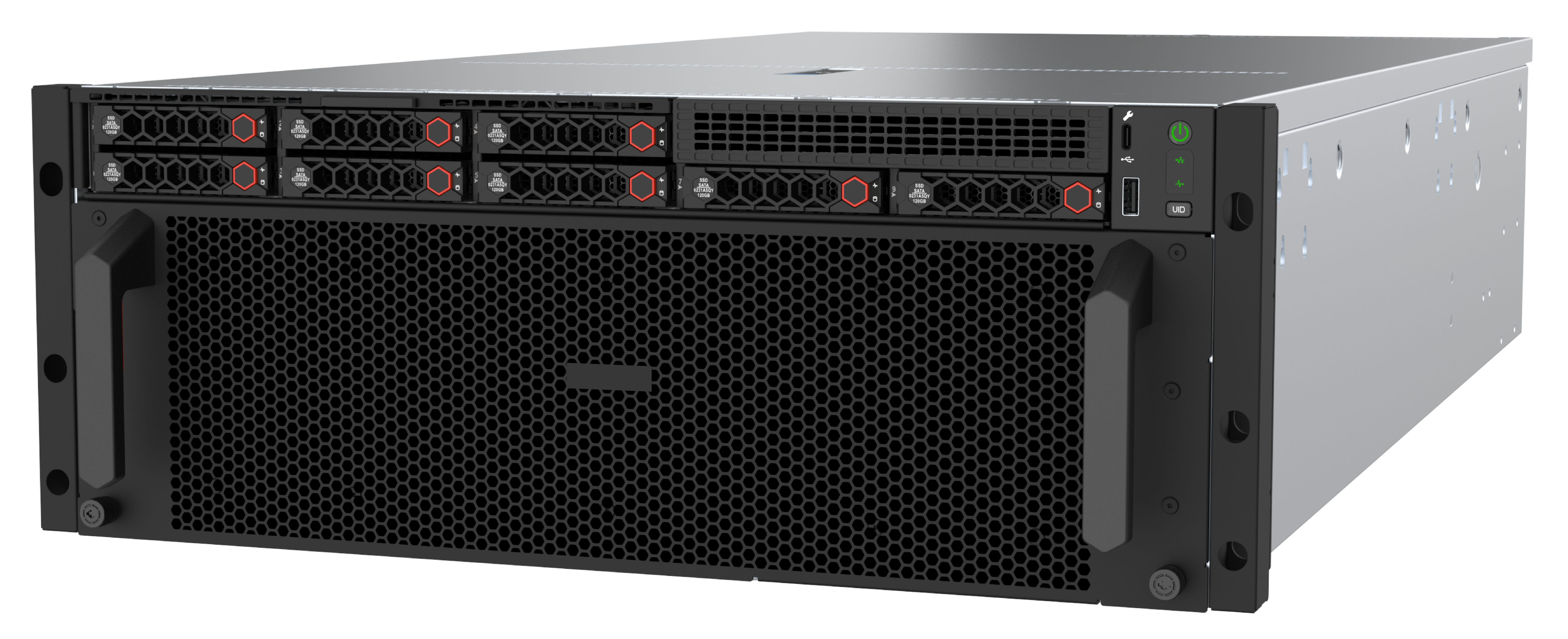
H3C UniServer R4500 G6 servers are a new generation 4U dual-processor rack servers developed on the Intel Eagle Stream platform. Their powerful storage performance meets current and future service expansion needs. The servers are widely used for next-generation cloud computing, Internet, IDC, and enterprise markets. The servers feature low power consumption, high reliability, high scalability, simplified management, and sfimplified deployment.
Figure 1 shows the appearance of the server.
Technical parameters
This section introduces the product specifications and technical parameters of the server.
Product specifications
Table 2 Product specifications
|
Item |
Specifications |
|
Processor |
· Supports up to two Intel Eagle Stream processors (SPR or EMR processors). A single SPR processor supports a maximum power consumption of 350W, and a single EMR processor supports a maximum power consumption of 385W. · For more information about processors, see Server-Compatible Components Lookup Tool. |
|
Memory |
Supports up to 32 DDR5 memory slots, with a maximum rate of 4800 MT/s with SPR processors and 5600MT/s with EMR processors. Supports RDIMMs. |
|
Storage controllers |
· Embedded VROC storage controller · Storage controller · NVMe VROC module · Serial & DSD module (supports RAID 1) |
|
Chipset |
Intel C741 Emmitsburg chipset |
|
Network ports |
· One embedded dedicated 1Gbps management port · 2 × OCP 3.0 network adapters (for 4 × 1GE copper ports, 2 × 10GE copper/fiber ports, 2 × 25GE fiber ports, or 2 × 100GE fiber ports) · Network adapters compatible with standard PCIe
slots |
|
Integrated graphics card |
The graphics card chip is integrated into the BMC chip, which is the AST2600 model. It supports a maximum resolution of 1920 x 1200 @ 60Hz (32 bits per pixel). · Resolution ratio: ¡ 1920 x 1200: 1920 horizontal pixels and 1200 vertical pixels ¡ 60 Hz: Screen refresh rate of 60 times per second ¡ 32Bpp: Color bits. Higher the color bits, more colors that can be displayed. ¡ In Windows systems, the 1920 x 1200 resolution ratio is supported only after the graphics card driver that matches the operating system version is installed. If the driver is not installed, the system can support only the default resolution ratio of the operating system. |
|
· 4 × USB connectors (one on the system board, two at the server rear, and one at the server front) · 12 × built-in SATA connectors (Showed as three external x4 SlimSAS connectors) · 10 × MCIO connectors (PCIe5.0 x8) · 1 × RJ-45 HDM dedicated network port (at the server rear) · 2 × VGA connectors (one at the server rear and one optional at the server front) · 1 × serial port (available only when a Serial&DSD module is installed) · 1 × HDM dedicated management port (at the server front) |
|
|
Expansion slots |
· Supports up to six PCIe standard slots (including five PCIe5.0 standard slots) · Supports up to two OCP 3.0 slots |
|
Optical drives |
External USB optical drive |
|
Management |
· HDM agentless management tool (with independent management port) · H3C iFIST/UniSystem management software · LCD management module · (Optional.) U-Center data center management platform |
|
4 × hot-swappable power supplies with 1+1 or 2+2 redundancy |
|
|
Accreditation |
CCC, UL, and CE |
Technical specifications
Table 3 Technical specifications
|
Category |
Item |
Specifications |
|
Physical parameters |
Dimensions (H × W × D) |
174.8mm*448mm*900mm |
|
Maximum weight |
95 kg (209.44 lb)
The server has a maximum net weight of 95 kg. If the non-matching rails or rack panels are used, make sure they can bear the server weight to avoid structural failure. |
|
|
Environmental specifications |
Temperature |
Operating temperature: 5°C to 40°C (41°F to 104°F) NOTE: The maximum operating temperature requirement for the server might be lower than that stated, depending on the hardware configuration. For more information, see operating temperature specifications in appendix A. |
|
Storage temperature: –40°C to +70°C (–40°F to +158°F) |
||
|
· Operating humidity: 8% to 90% (non-condensing) · Storage humidity: 5% to 95% (non-condensing) |
||
|
· Operating altitude: –60 m to +3000 m (–196.85 ft to +9842.52 ft) · · Storage altitude: -60m to 5000m (–196.85 ft to +16404.20 ft) |
Components
This section describes components of the server.
Figure 2 Server components
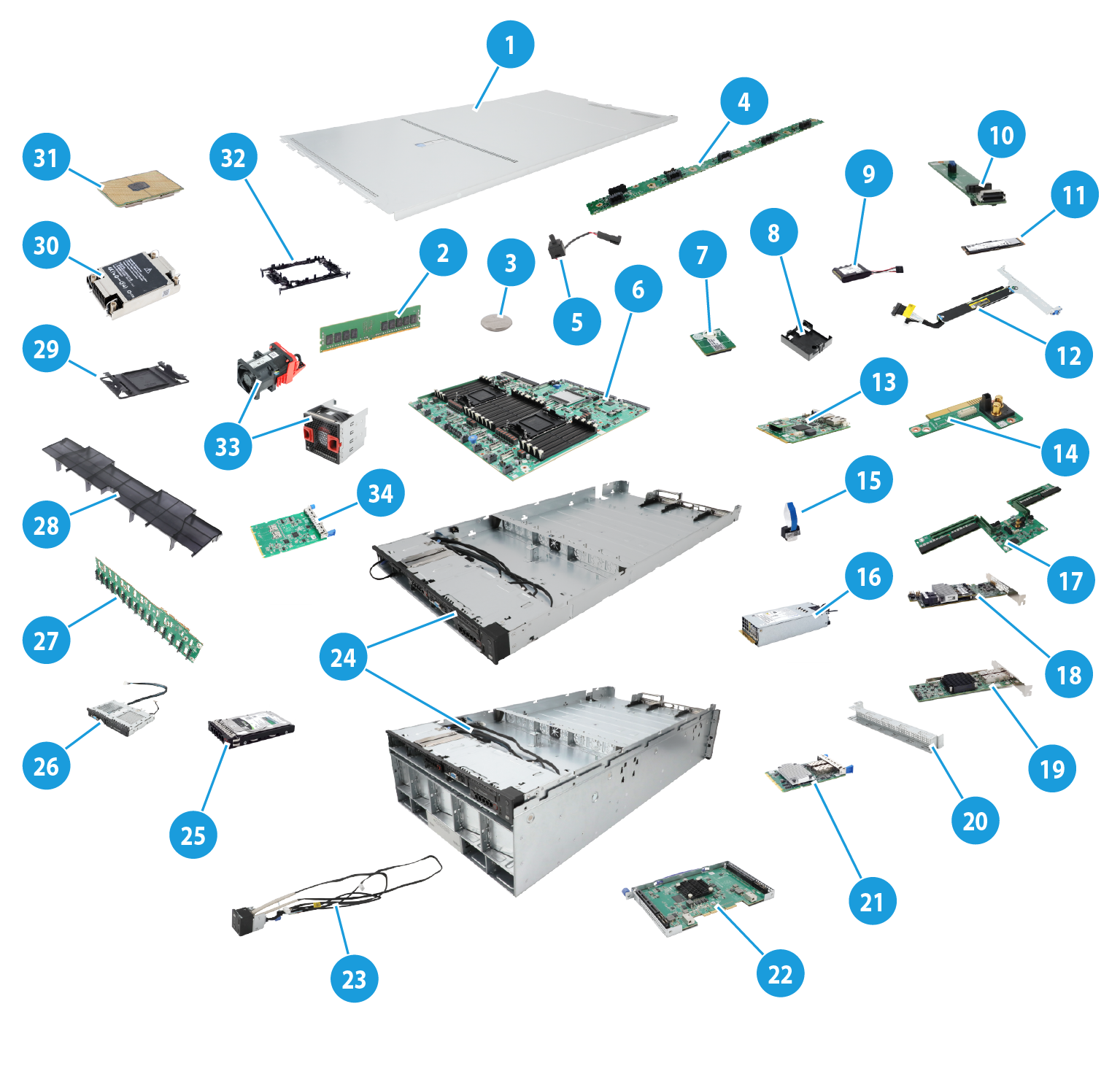
Table 4 Description of server components
|
No. |
Name |
Description |
|
1 |
Chassis access panel |
N/A |
|
2 |
Memory |
Temporarily stores operational data in the CPU and data exchanged with external storage devices such as drives. DDR5 memory is supported. |
|
3 |
System battery |
Powers the system clock to ensure a correct system date and time. |
|
4 |
Fan adapter module |
Provides heat dissipation for mid 60LFF drives and expander modules. |
|
5 |
Chassis-open alarm module |
Detects if the access panel is removed. The detection result can be displayed from the HDM Web interface. |
|
6 |
System board |
One of the most important parts of a server, on which multiple components are installed, such as processor, memory, and fan. It is integrated with basic server components, including the BIOS chip and PCIe connectors. |
|
7 |
Encryption module |
Provides encryption services for the server to enhance data security. |
|
8 |
Supercapacitor holder |
Secures a supercapacitor in the chassis. |
|
9 |
Supercapacitor |
Supplies power to the flash card on the power fail safeguard module, which enables the storage controller to back up data to the flash card for protection when a power outage occurs. |
|
10 |
SATA M.2 SSD adapter |
An SATA M.2 SSD is installed in the server through an SATA M.2 SSD adapter. |
|
11 |
SATA M.2 SSD |
Provides data storage space for the server. |
|
12 |
Riser card |
Provides PCIe slots. |
|
13 |
Server management module |
Provides various IO connectors and HDM out-of-band management feature for the server. |
|
14 |
Upper power distribution board |
Controls and adapts power supplies for the server together with the lower power distribution board. |
|
15 |
NVMe VROC module |
An NVMe VROC module is used to activate the RAID features of NVMe SSDs. It works in conjunction with the VMD technology to enable NVMe drive array functionality. |
|
16 |
Power module |
Supplies power to the server. The power supplies support hot swapping and 1+1 redundancy. |
|
17 |
Lower power distribution board |
Controls and adapts power supplies for the server together with the upper power distribution board. |
|
18 |
Storage controller |
Provides RAID support for SAS/SATA drives, including RAID configuration and RAID scale-up. Online upgrade of RAID controller firmware and remote configuration are supported. |
|
19 |
Standard PCIe network adapter |
Installed in a standard PCIe slot to provide network ports. |
|
20 |
Riser card filler panel |
Installed on an empty PCIe riser connector to ensure good ventilation. |
|
21 |
OCP network adapter |
Network adapter installed onto the OCP network adapter connector on the system board. |
|
22 |
Expander module |
Installed at the bottom of the 60LFF drive cage, supporting 30LFF expansion. |
|
23 |
Multifunctional rack mount kit |
The right-side mounting ear integrates front I/O components, including a dedicated HDM management interface and a USB 2.0 connector. |
|
24 |
Chassis |
Encloses all server components. |
|
25 |
Drives |
Provides data storage for the server, supporting hot swapping. |
|
26 |
Front IO expander module |
Provides a VGA connector for the server. |
|
27 |
Drive backplane |
Provides power and data channels for drives. This document uses mid 15LFF drive backplanes as an example. |
|
28 |
Air baffle |
Provides ventilation aisles for processor heatsinks and memory modules and provides support for the supercapacitor. |
|
29 |
Processor socket cover |
Installed over an empty processor socket to protect pins in the socket. When no processor is present, the cover protects the processor slot on the system board. |
|
30 |
Processor heatsink |
Cools the processor. |
|
31 |
Processor |
Integrates memory and PCIe controllers to provide data processing capabilities for the server. |
|
32 |
Processor retaining bracket |
Attaches a processor to the heatsink. |
|
33 |
Fan |
Helps server ventilation. Fans support hot swapping and N+1 redundancy. |
|
34 |
Serial&DSD module |
Provides a serial port and dual SD card slots for the server. |
Front panel
This section describes components, LEDs, and ports on the front panel.
Front panel
Figure 3 Front panel (8SFF drive configuration)
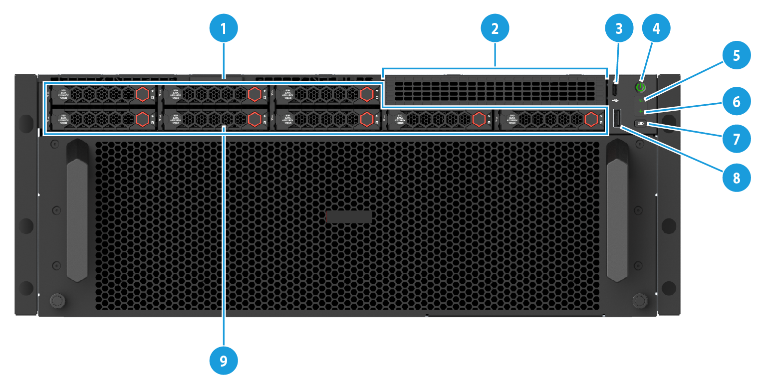
Table 5 Front panel components (8SFF drive configuration)
|
No. |
Specification |
|
1 |
Serial label pull tab |
|
2 |
2SFF drive or PCIe riser card slot (for processor 1), or front IO expander module (supporting one VGA connector) |
|
3 |
HDM dedicated management connector |
|
4 |
Power On/Standby button and system power LED |
|
5 |
OCP network adapter interface LED |
|
6 |
Health LED |
|
7 |
UID button LED |
|
8 |
USB 2.0 port |
|
9 |
8SFF drive* |
|
*: Different drive backplanes support different types of drives. For more information about drive backplanes, see "Drive backplane." |
|
LEDs and buttons
Front panel LEDs and buttons
Figure 4 Front panel LEDs and buttons
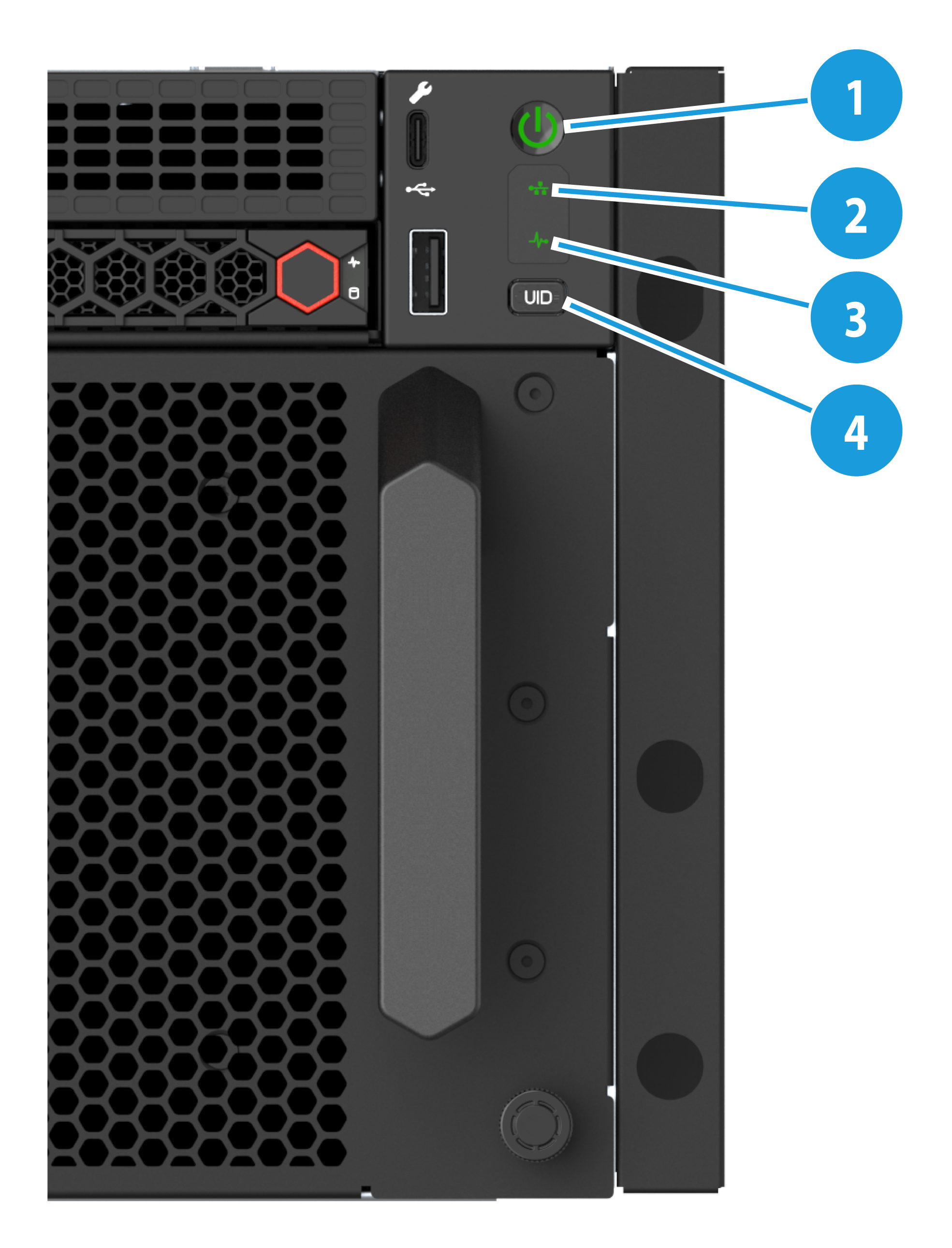
Table 6 Description of front panel LEDs and buttons
|
No. |
Specification |
State |
|
1 |
Power On/Standby button and system power LED |
· Steady green—The system has started. · Flashing green (1 Hz)—The system is starting. · Steady amber—The system is in standby state. · Off—No power is present. |
|
2 |
OCP 3.0 network adapter Ethernet port LED |
· Steady green—A link is present on a port of an OCP 3.0 network adapter. · Flashing green (1 Hz)—A port on an OCP 3.0 network adapter is receiving or sending data. · Off—No link is present on any port of either OCP 3.0 network adapter. NOTE: The server supports a maximum of two OCP3.0 network adapters. |
|
3 |
Health LED |
· Steady green—The system is operating correctly or a minor alarm has occurred. · Flashing green (4 Hz)—HDM is being initialized. · Flashing amber (1 Hz)—A major alarm has occurred. · Flashing red (1 Hz)—A critical alarm has occurred. |
|
4 |
UID button/LED |
· Steady blue—UID LED is activated. The UID LED can be activated by using the following methods: ¡ The UID button is pressed. ¡ Enable UID LED from HDM. · Flashing blue: ¡ 1 Hz—The system is being remotely managed or HDM is performing out-of-band firmware update. Do not power off the device. ¡ 4 Hz—HDM is restarting. To restart HDM, press the UID button LED for a minimum of 8 seconds. · Off—UID LED not activated. |
|
· If a system alarm is present, log in to HDM to obtain more information about the system running status. · Possible causes for power LED off state: ¡ No power source is connected. ¡ No power supplies are present. ¡ The installed power supplies are faulty. ¡ The system power cords are not connected correctly. |
||
Connectors
Table 7 Front panel connectors
|
API Name |
Data type |
Purpose |
|
VGA connector |
DB15 |
Connects a display terminal, such as a monitor or KVM device. |
|
USB connector |
USB 3.0/2.0 |
Connects the following devices: · USB flash drive. · USB keyboard or mouse. · USB optical drive for operating system installation. |
|
HDM dedicated management connector |
Type-C |
Connects a Type-C to USB adapter cable, which connects to a USB Wi-Fi adapter or USB drive. |
Rear panel
This section describes components, LEDs, and ports on the rear panel.
Rear panel
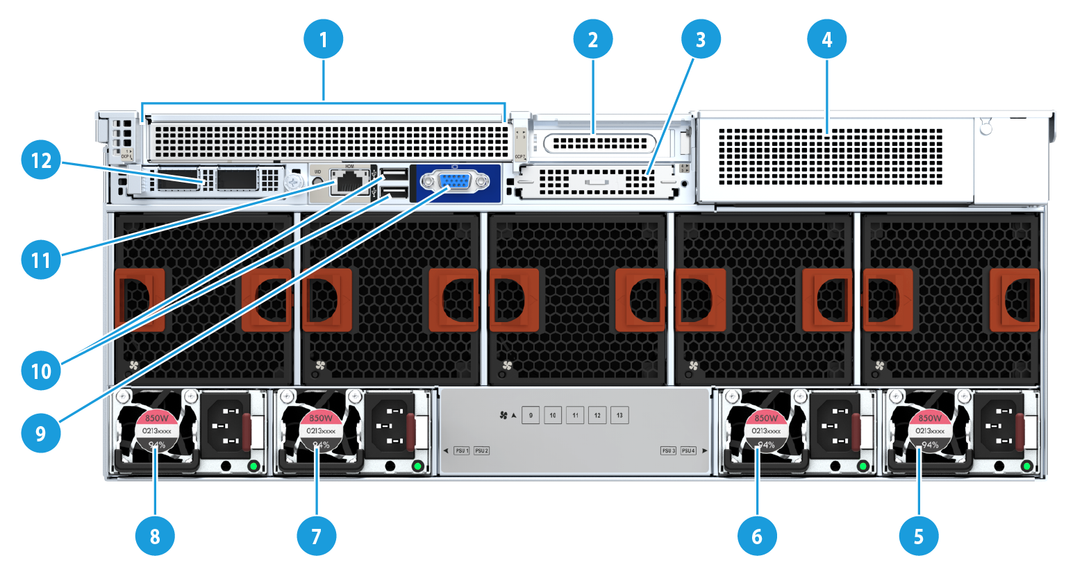
Table 8 Rear panel components
|
Specification |
||
|
1 |
PCIe Riser card slot 1: PCIe slot 1 to slot 2 |
|
|
2 |
PCIe Riser card slot 3: PCIe slot 3 |
|
|
3 |
OCP 3.0 network adapter or Serial&DSD module (slot 8)(optional) |
|
|
4 |
PCIe slot 4 to slot 5 |
|
|
5 |
Power supply 4 |
|
|
6 |
Power supply 3 |
|
|
7 |
Power supply 2 |
|
|
8 |
Power supply 1 |
|
|
9 |
VGA connector |
|
|
10 |
Two USB 3.0 connectors |
|
|
11 |
HDM dedicated connector (1 Gbps, RJ-45, default IP address 192.168.1.2/24) |
|
|
12 |
Optional OCP3.0 network adapter (slot 7) |
|
|
For more information about the serial&DSD module, see "Serial & DSD module." |
||
Rear panel LEDs
Figure 6 Rear panel LEDs
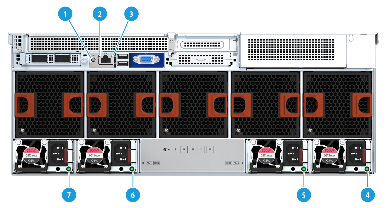
Table 9 Rear panel LEDs
|
Specification |
State |
|
|
1 |
UID LED |
· Steady blue—The UID LED is activated. You can use the following methods to activate the UID LED: ¡ Press the UID button. ¡ Enable UID LED from HDM. · Flashing blue: ¡ 1 Hz—The system is being remotely managed or HDM is performing out-of-band firmware update. Do not power off the device. ¡ 4 Hz—HDM is restarting. To restart HDM, press the UID button LED for a minimum of 8 seconds. · Off—UID LED not activated. |
|
2 |
Link LED of the Ethernet port |
· Steady green—A link is present on the port. · Off—No link is present on the port. |
|
3 |
Activity LED of the Ethernet port |
· Flashing green (1 Hz)—The port is receiving or sending data. · Off—The port is not receiving or sending data. |
|
4 |
Power supply 1 status LED |
· Steady green: The power supply is operating correctly. · Flashing green (0.33 Hz)—The power supply is in standby state and does not output power. · Flashing green (2 Hz)—The power supply is updating its firmware. · Steady amber—Either of the following conditions exists: ¡ The power module has experienced a critical fault. ¡ The power module has no input, but the other power module has normal input. · Flashing amber (1 Hz)—An alarm has occurred on the power supply. · Off—No power supplies have power input, which can be caused by an incorrect power cord connection or power source shutdown. |
|
5 |
Power supply 2 status LED |
Connectors
Table 10 Rear panel connectors
|
API Name |
Data type |
Purpose |
|
VGA connector |
DB15 |
Connects a display terminal, such as a monitor or KVM device. |
|
Serial connector |
RJ45 |
The serial port is used for the following purposes: · Log in to the server when the remote network connection to the server has failed. · Establish a GSM modem or encryption lock connection. NOTE: The serial port resides on the serial port and DSD module. For more information, see "Serial & DSD module." |
|
USB connector |
USB 3.0 |
Connects the following devices: · USB flash drive. · USB keyboard or mouse. · USB optical drive for operating system installation. |
|
HDM dedicated network connector |
Establishes a network connection to manage HDM from its Web interface. |
|
|
Power connector |
Standard single-phase |
Connects the power supply to the power source. |
System board
This section describes system board components.
System board layout

Table 11 System board layout
|
ID |
Description |
Mark |
|
1 |
PCIe Riser card slot 3 (for processor 2) |
RISER3 PCIe X16 |
|
2 |
Fan connector 2 for the OCP 3.0 network adapter |
OCP2 FAN |
|
3 |
OCP 3.0 network adapter connector 2/DSD module connector |
OCP2&DSD&UART CARD |
|
4 |
PCIe Riser card slot 1 (for processor 1) |
RISER1 PCIe X16 |
|
5 |
Server management module connector |
BMC |
|
6 |
Fan connector 1 for the OCP 3.0 network adapter |
OCP1 FAN |
|
7 |
OCP 3.0 network adapter connector 1 |
OCP1 |
|
8 |
SlimSAS connector 3 (x4 SATA) |
SATA PORT3 |
|
9 |
SlimSAS connector 2 (x4 SATA) |
SATA PORT2 |
|
10 |
SlimSAS connector 1 (x4 SATA or M.2 SSD) |
M.2&SATA PORT1 |
|
11 |
Front I/O connector |
RIGHT EAR |
|
12 |
Lower power distribution boardAUX connector 7 |
AUX7 |
|
13 |
M.2 SSD AUX connector |
M.2 AUX |
|
14 |
Fan module connector 8 |
FAN8 |
|
15 |
LCD module connector |
DIAG LCD |
|
16 |
MCIO connector C1-P4A (x8 PCIe5.0, for processor 1) |
C1-P4A |
|
17 |
Fan module connector 7 |
FAN7 |
|
18 |
MCIO connector C1-P4C (x8 PCIe5.0, for processor 1) |
C1-P4C |
|
19 |
Fan module connector 6 |
FAN6 |
|
20 |
MCIO connector C1-P3C (x8 PCIe5.0, for processor 1) |
C1-P3C |
|
21 |
Fan module connector 5 |
FAN5 |
|
22 |
MCIO connector C1-P3A (x8 PCIe5.0, for processor 1) |
C1-P3A |
|
23 |
Power connector 3 for the front drive backplane |
PWR3 |
|
24 |
Power connector 2 for the front drive backplane |
PWR2 |
|
25 |
Connector for the air inlet thermal sensor module |
N/A |
|
26 |
Power connector 1 for the front drive backplane |
PWR1 |
|
27 |
Fan module connector 4 |
FAN4 |
|
28 |
MCIO connector C2-P4A (x8 PCIe5.0, for processor 2) |
C2-P4A |
|
29 |
Fan module connector 3 |
FAN3 |
|
30 |
MCIO connector C2-P4C (x8 PCIe5.0, for processor 2) |
C2-P4C |
|
31 |
Fan module connector 2 |
FAN2 |
|
32 |
AUX connector 2 for the front drive backplane |
AUX2 |
|
33 |
AUX connector 1 for the front drive backplane |
AUX1 |
|
34 |
Fan module connector 1 |
FAN1 |
|
35 |
Chassis-open alarm module |
INTRUDER |
|
36 |
Front VGA and USB 2.0 connector |
LEFT EAR |
|
37 |
Power connector 4 for the rear drive backplane |
PWR4 |
|
38 |
Riser card power connector 6 |
PWR6 |
|
39 |
Power connector 5 for the rear drive backplane |
PWR5 |
|
40 |
MCIO connector C2-P2C (for processor 2) |
C2-P2C |
|
41 |
AUX connector 5 for the rear drive backplane |
AUX5 |
|
42 |
MCIO connector C2-P2A (for processor 2) |
C2-P2A |
|
43 |
Riser card AUX connector 8 |
AUX8 |
|
44 |
NVMe VROC module connector |
NVMe RAID KEY |
|
45 |
TPM/TCM connector |
TPM |
|
46 |
System battery |
N/A |
|
47 |
MCIO connector C1-P2C (for processor 1) |
C1-P2C |
|
48 |
MCIO connector C1-P2A (for processor 1) |
C1-P2A |
|
49 |
Built-in USB 2.0 connector |
INTERNAL USB2.0 |
|
X |
System maintenance switch |
MAINTENANCE |
|
PCIe5.0 x8 description: · PCIe5.0: Fifth-generation signal rate. · x8: Bus bandwidth. |
||
System maintenance switch
The system maintenance switch has 8 pins, as shown in Figure 8.
Figure 8 System maintenance switch
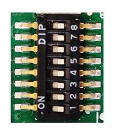
The following problems can be solved with the system maintenance switch. Table 12 describes meanings of the system maintenance switch and "Figure 8" shows the layout.
· Users forget the HDM login user name or password and cannot log in to HDM.
· Users forget the BIOS password and cannot enter BIOS.
· Default BIOS settings should be restored.
Table 12 System maintenance switch description
|
Location |
Description (Off by default) |
Remarks |
|
1 |
Off—HDM login requires the username and password of a valid HDM user account. On—HDM login requires the default username and password. |
For security purposes, turn off the switch after you complete tasks with the default username and password as a best practice. |
|
5 |
Off—Normal server startup. ON— Restores the default BIOS settings during server startup. |
To restore the default BIOS settings, turn on and then turn off the switch. The server starts up with the default BIOS settings at the next startup.
The server cannot start up when the switch is turned on. To avoid service data loss, stop running services and power off the server before turning on the switch. |
|
6 |
Off—Normal server startup. On—Clears all passwords from the BIOS at server startup. |
If this switch is on, the server will clear all the passwords at each startup. Make sure you turn off the switch before the next server startup if you do not need to clear all the passwords. |
|
2, 3, 4, 7, and 8 |
Reserved for future use. |
|
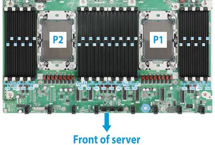
DIMM slots
A0, B0…H0, A1, B1…H1 represent the DIMM slot numbers. For installation guidelines of DIMMs, see "Memory."
Figure 9 System board DIMM slots
Drives
Drive numbering
Drive numbers are used to indicate drive positions, and they are exactly the same as the marks at the front and rear of the server.
For the correspondence between the physical number of a drive and the number displayed in HDM and BIOS, see the drive slot number table in appendix C.
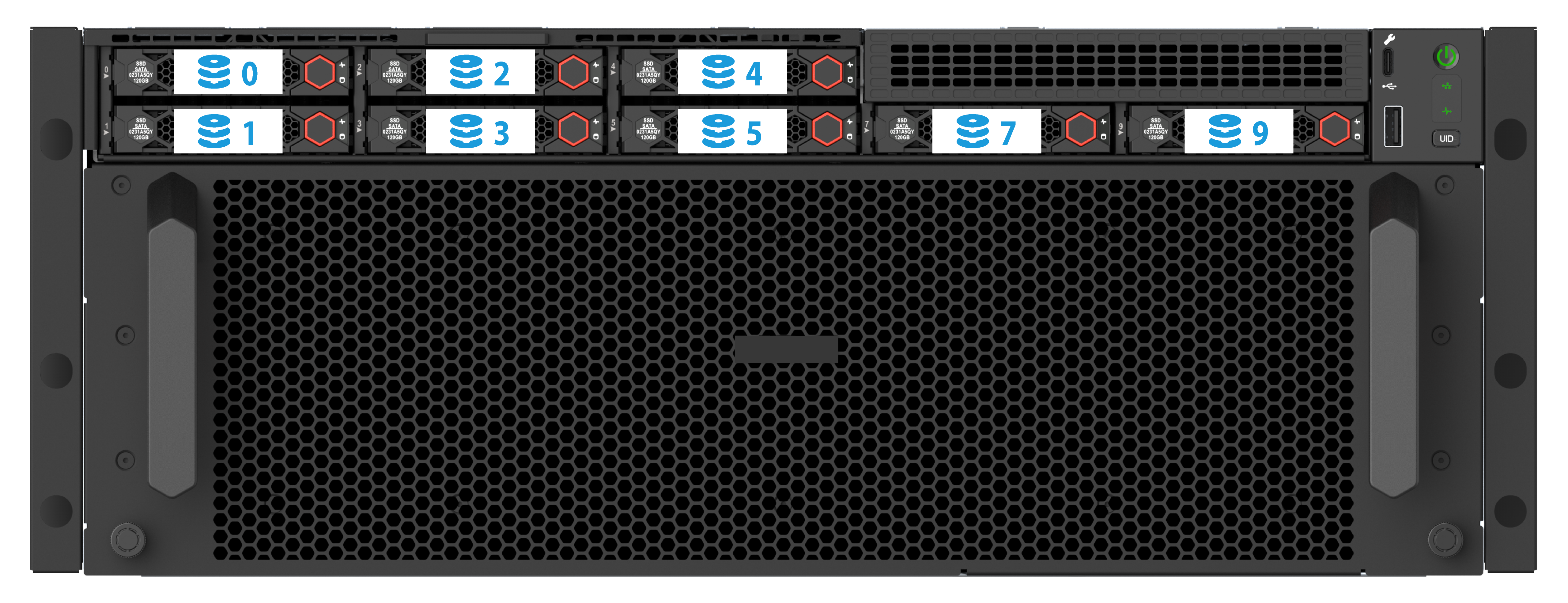
Figure 11 Front 10SFF

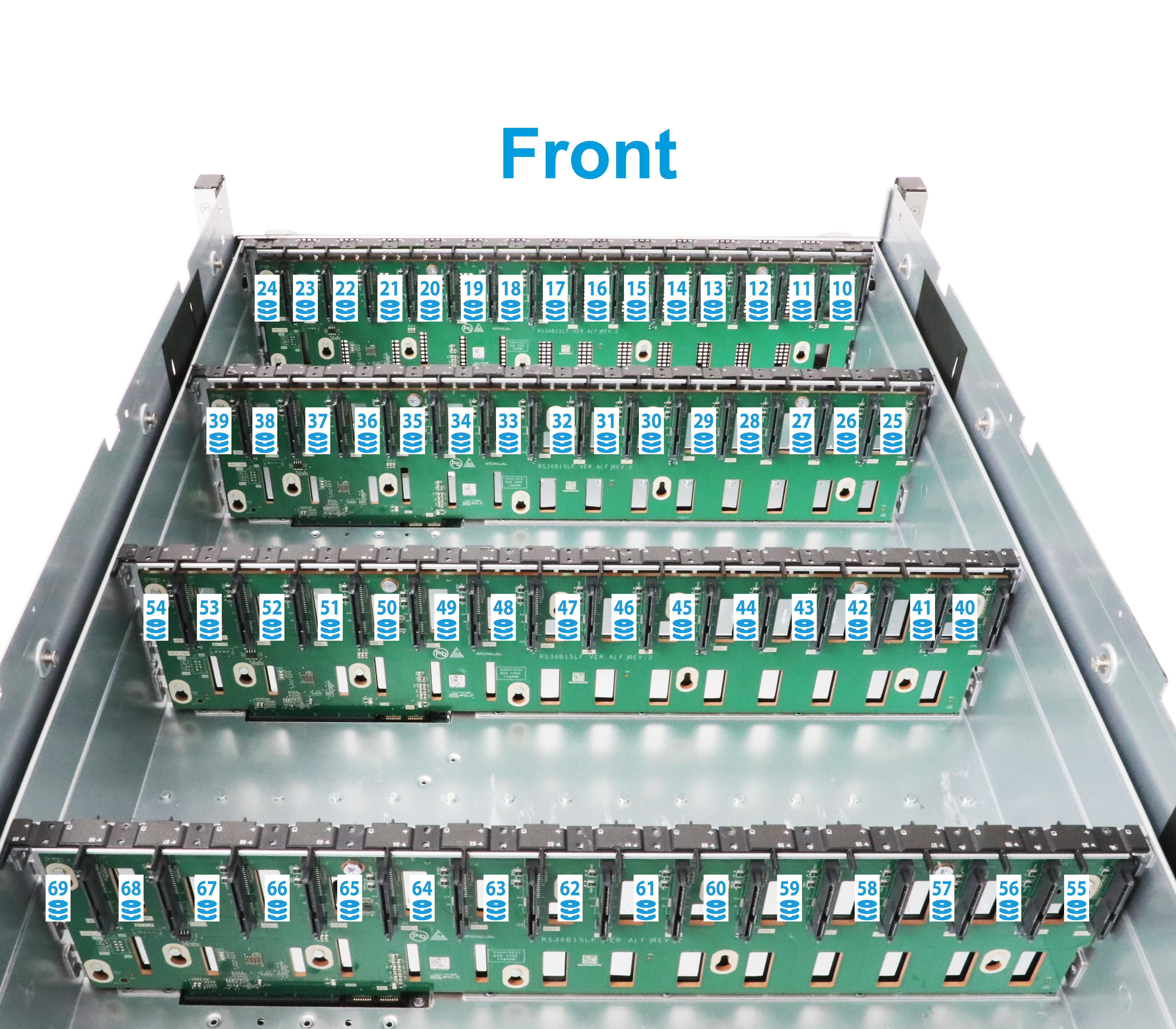
Figure 12 Four mid 15LFF drives
Drive LEDs
The server supports SAS/SATA/NVMe drives. You can view the state of a drive through its LED.
Figure 13 Drive LEDs (1)
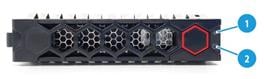
|
(1) Fault/UID LED |
(2) Present/Active LED |
Figure 14 Drive LEDs (2)
|
(1) Fault/UID LED |
(2) Present/Active LED |
Table 13 SAS/SATA drive LEDs
|
Fault/UID LED status |
Present/Active LED status |
Description |
|
Steady green/Flashing green (4.0 Hz) |
A drive failure is predicted. As a best practice, replace the drive before it fails. |
|
|
Steady amber |
Steady green/Flashing green (4.0 Hz) |
The drive is faulty. Replace the drive immediately. |
|
Steady blue |
Steady green/Flashing green (4.0 Hz) |
The drive is operating correctly and is selected by the RAID controller. |
|
Off |
Flashing green (4.0 Hz) |
The drive is performing a RAID migration or rebuilding, or the system is reading or writing data to the drive. |
|
Off |
Steady green |
The drive is present but no data is being read or written to the drive. |
|
Off |
Off |
The drive is not securely installed. |
Table 14 NVMe drive LEDs
|
Fault/UID LED status |
Present/Active LED status |
Description |
|
Flashing amber (4Hz) |
Off |
The drive is in hot insertion. |
|
Steady amber |
Steady green/Flashing green (4.0 Hz) |
The drive is faulty. Replace the drive immediately. |
|
Steady blue |
Steady green/Flashing green (4.0 Hz) |
The drive is operating correctly and selected by the RAID controller. |
|
Off |
Flashing green (4.0 Hz) |
The drive is performing a RAID migration or rebuilding, or the system is reading or writing data to the drive. |
|
Off |
Steady green |
The drive is present but no data is being read or written to the drive. |
|
Off |
Off |
The drive is not securely installed. |
Drive backplane
This section introduces the drive backplanes supported by the server, including components of the backplanes and the types and numbers of drives supported by the backplanes.
Drive backplanes are classified by the type of drives supported, including general drive backplanes, NVMe drive backplanes, and UniBay drive backplanes. A general drive backplane supports only SAS/SATA drives, an NVMe drive backplane supports only NVMe drives, and a UniBay drive backplane supports both SAS/SATA and NVMe drives.
|
|
NOTE: · A UniBay drive backplane supports both SAS/SATA and NVMe drives only when the backplane is connected to both SAS/SATA and NVMe data cables. · The number of SAS/SATA drives and the number of NVMe drives supported by a UniBay drive backplane vary by cabling scheme. |
Front 8SFF UniBay drive backplane
The 8SFF UniBay drive backplane (model: PCA-BP-8UniBay-1U-G6) is installed at the server front to support a maximum of eight 2.5-inch SAS/SATA/NVMe drives. Table 15 shows the drive backplane components.
Figure 15 8SFF UniBay drive backplane
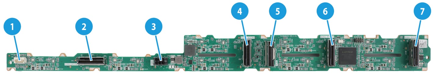
Table 15 8SFF UniBay drive backplane components
|
No. |
Description |
Mark |
|
1 |
AUX connector |
AUX1 |
|
2 |
MCIO connector A1/A2 (PCIe5.0 x8) |
NVMe A1/A2 |
|
3 |
Power connector |
PWR1 |
|
4 |
MCIO connector A3/A4 (PCIe5.0 x8) |
NVMe A3/A4 |
|
5 |
SAS/SATA connector |
SAS PORT |
|
6 |
MCIO connector B1/B2 (PCIe5.0 x8) |
NVMe B1/B2 |
|
7 |
MCIO connector B3/B4 (PCIe5.0 x8) |
NVMe B3/B4 |
|
PCIe5.0 x8 description: · PCIe5.0: Fifth-generation signal rate. · x8: Bus bandwidth. |
||
Front 2SFF UniBay drive backplane
The 2SFF UniBay drive backplane (model: HDDCage-2UniBay-1U-G6) is installed at the server front to support a maximum of two 2.5-inch SAS/SATA/NVMe drives. Table 16 describes the backplane components.
Figure 16 2SFF UniBay drive backplane
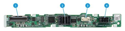
Table 16 2SFF UniBay drive backplane components
|
No. |
Description |
Mark |
|
1 |
SlimSAS connector A1/A2 (PCIe4.0 x8) |
NVME-A1/A2 |
|
2 |
x4 Mini-SAS-HD connector |
SAS PORT |
|
3 |
AUX connector |
AUX |
|
4 |
Power connector |
PWR |
|
PCIe4.0 x8 description: · PCIe4.0: Fourth-generation signal rate. · x8: Bus bandwidth. |
||
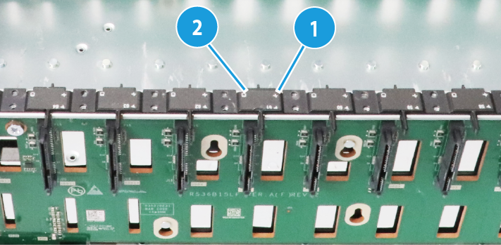
Mid 15LFF drive backplane
The 15LFF drive backplane (model: BP-15LFF-G6) is installed inside the chassis to support a maximum of fifteen 3.5-inch SAS/SATA drives. Table 17 describes the backplane components.
Figure 17 15LFF drive backplane
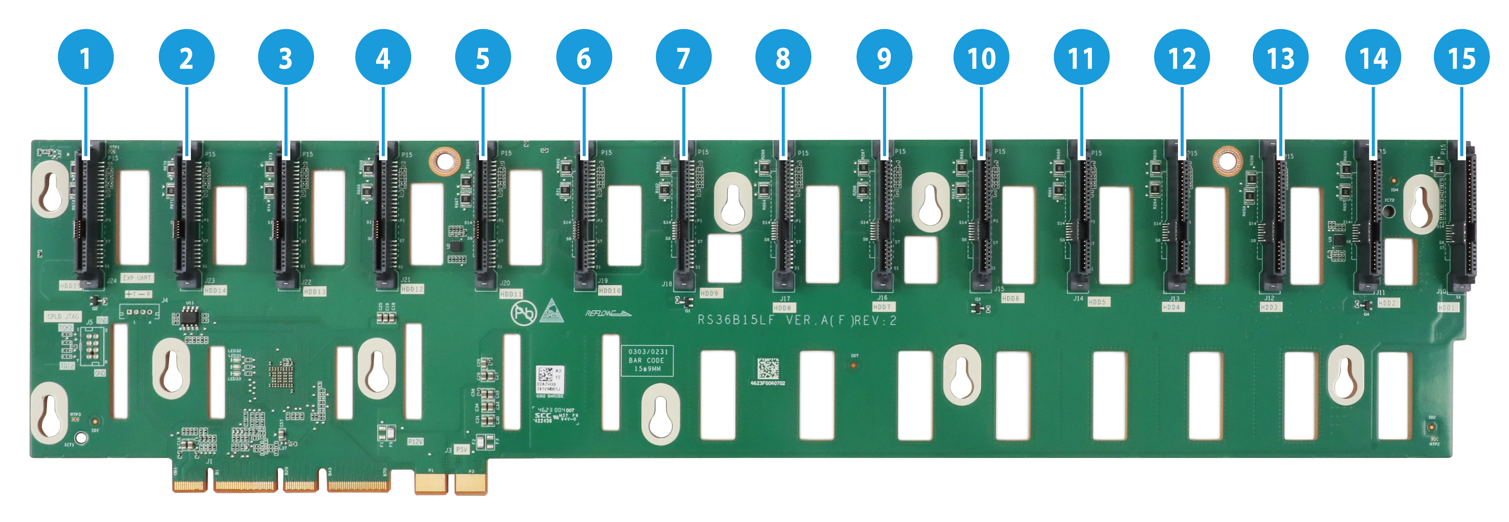
Table 17 15LFF UniBay drive backplane components
|
No. |
Specification |
Mark |
|
1 |
SAS/SATA connector |
HDD15 |
|
2 |
SAS/SATA connector |
HDD14 |
|
3 |
SAS/SATA connector |
HDD13 |
|
4 |
SAS/SATA connector |
HDD12 |
|
5 |
SAS/SATA connector |
HDD11 |
|
6 |
SAS/SATA connector |
HDD10 |
|
7 |
SAS/SATA connector |
HDD9 |
|
8 |
SAS/SATA connector |
HDD8 |
|
9 |
SAS/SATA connector |
HDD7 |
|
10 |
SAS/SATA connector |
HDD6 |
|
11 |
SAS/SATA connector |
HDD5 |
|
12 |
SAS/SATA connector |
HDD4 |
|
13 |
SAS/SATA connector |
HDD3 |
|
14 |
SAS/SATA connector |
HDD2 |
|
15 |
SAS/SATA connector |
HDD1 |
Riser cards
The server supports the following riser cards:
· RC-2FHFL-1U-SW-G6
· RC-1HHHL-R2-1U-SW
· RC-2FHHL-1U
· RC-1HHHL-R4-1U-X16-G5
For description and installation guidelines of riser cards, see "Riser cards and PCIe modules."
RC-2FHFL-1U-SW-G6
Figure 18 RC-2FHFL-1U-SW-G6
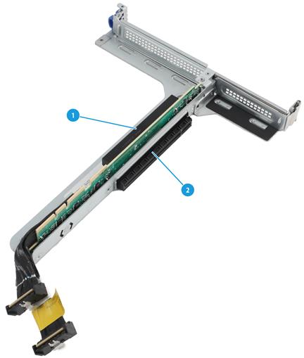
Table 18 RC-2FHFL-1U-SW-G6 Riser card components
|
No. |
Description |
|
1 |
PCIe5.0 x16 slot 1 |
|
2 |
PCIe5.0 x16 slot 2 |
RC-1HHHL-R3-1U-SW
Figure 19 RC-1HHHL-R3-1U-SW
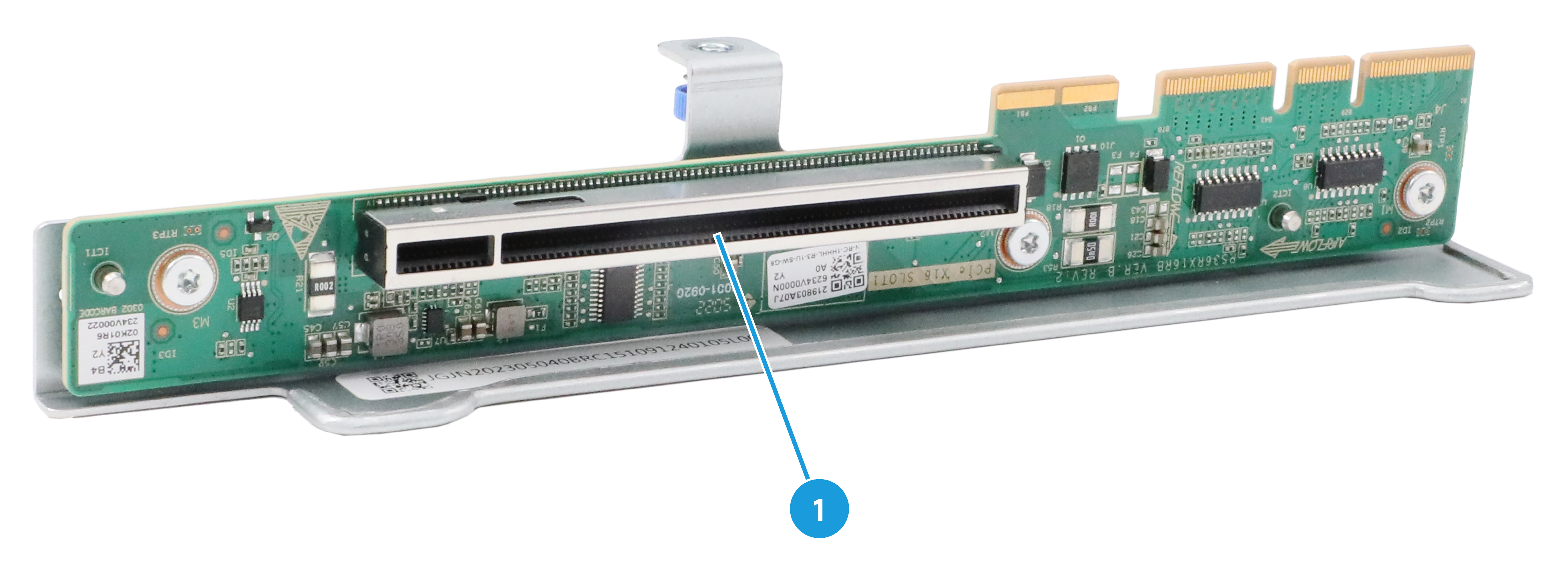
Table 19 RC-1HHHL-R3-1U-SW Riser card components
|
No. |
Specification |
|
1 |
PCIe5.0 x16 slot 3 |
RC-2FHHL-1U
Figure 20 RC-2FHHL-1U-1
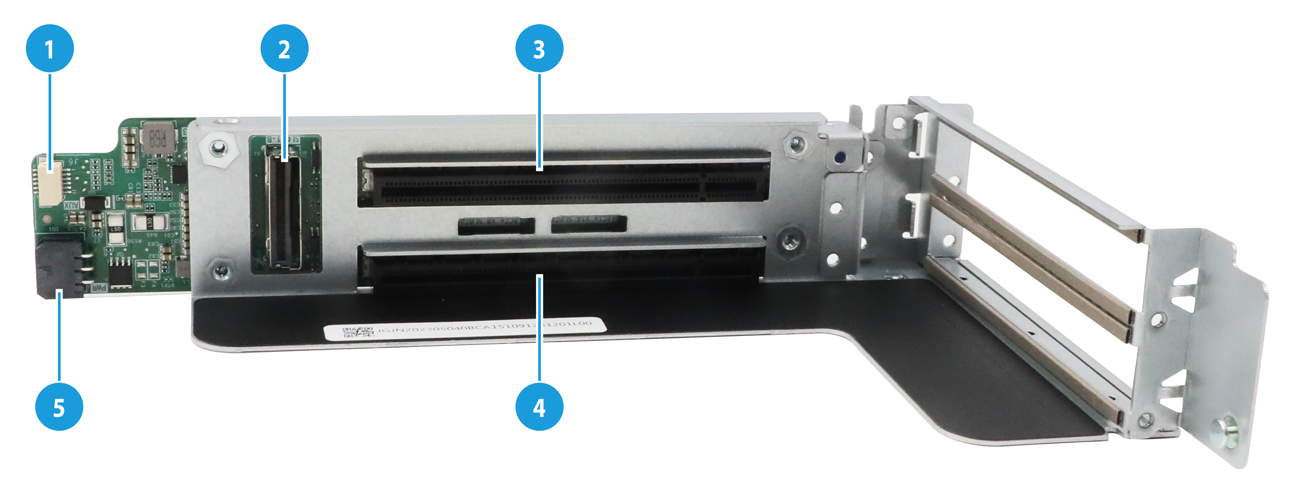
Figure 21 RC-2FHHL-1U-2
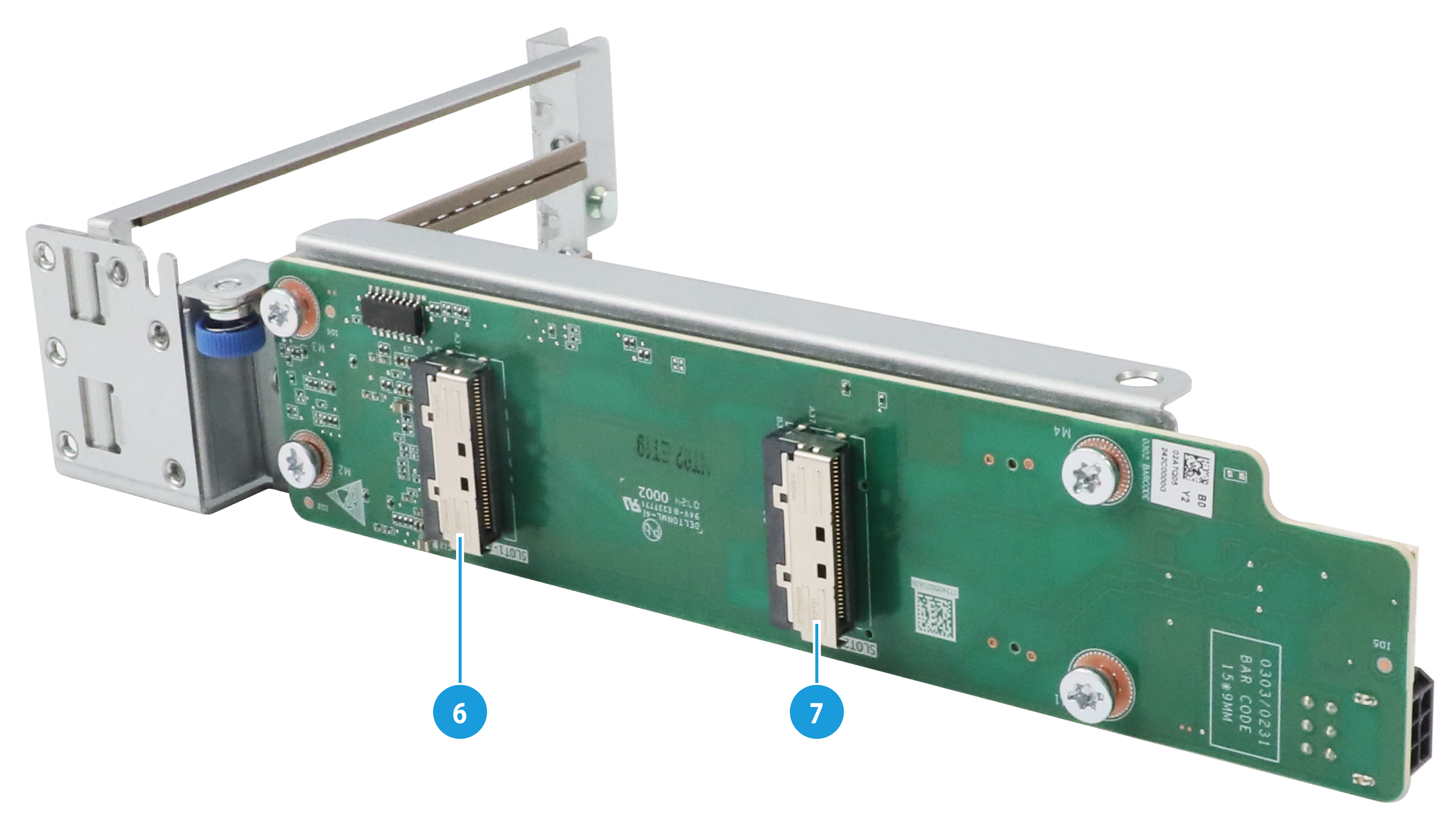
Table 20 RC-2FHHL-1U Riser card components
|
No. |
Specification |
|
1 |
AUX connector |
|
2 |
SLOT1-B |
|
3 |
PCIe5.0 x8 slot 5 |
|
4 |
PCIe5.0 x16 slot 4 |
|
5 |
Power connector |
|
6 |
SLOT1-A |
|
7 |
SLOT2-A |
RC-1HHHL-R4-1U-X16-G5
Figure 22 RC-1HHHL-R4-1U-X16-G5
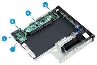
Table 21 RC-1HHHL-R4-1U-X16-G5 Riser card components
|
No. |
Specification |
|
1 |
Power connector |
|
2 |
AUX connector |
|
3 |
SlimSAS connector 1 |
|
4 |
PCIe4.0 x16 slot 6 |
|
5 |
SlimSAS connector 2 |
LCD smart management module
An LCD smart management module displays basic server information, operating status, and fault information, and provides diagnostics and troubleshooting capabilities. You can locate and troubleshoot component failures by using the LCD module in conjunction with the event logs generated in HDM.
For more information, see the LCD smart management module user guide.
Figure 23 LCD smart management module
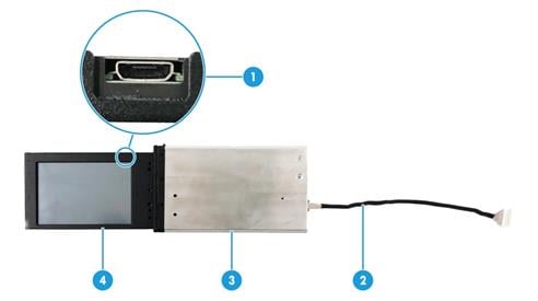
Table 22 LCD smart management module components
|
No. |
Item |
Description |
|
1 |
Mini-USB connector |
Used for upgrading the firmware of the LCD module. |
|
2 |
LCD module cable |
Connects the LCD module to the system board of the server. For information about the LCD smart management module connector on the system board, see "System board layout." |
|
3 |
LCD module shell |
Protects and secures the LCD screen. |
|
4 |
LCD screen |
Displays basic server information, operating status, and fault information. |
|
To install an LCD smart management module, prepare a compatible cable. For more information, see "Connecting LCD smart management module." |
||
Upper power distribution board
Figure 24 Upper 1U power distribution board
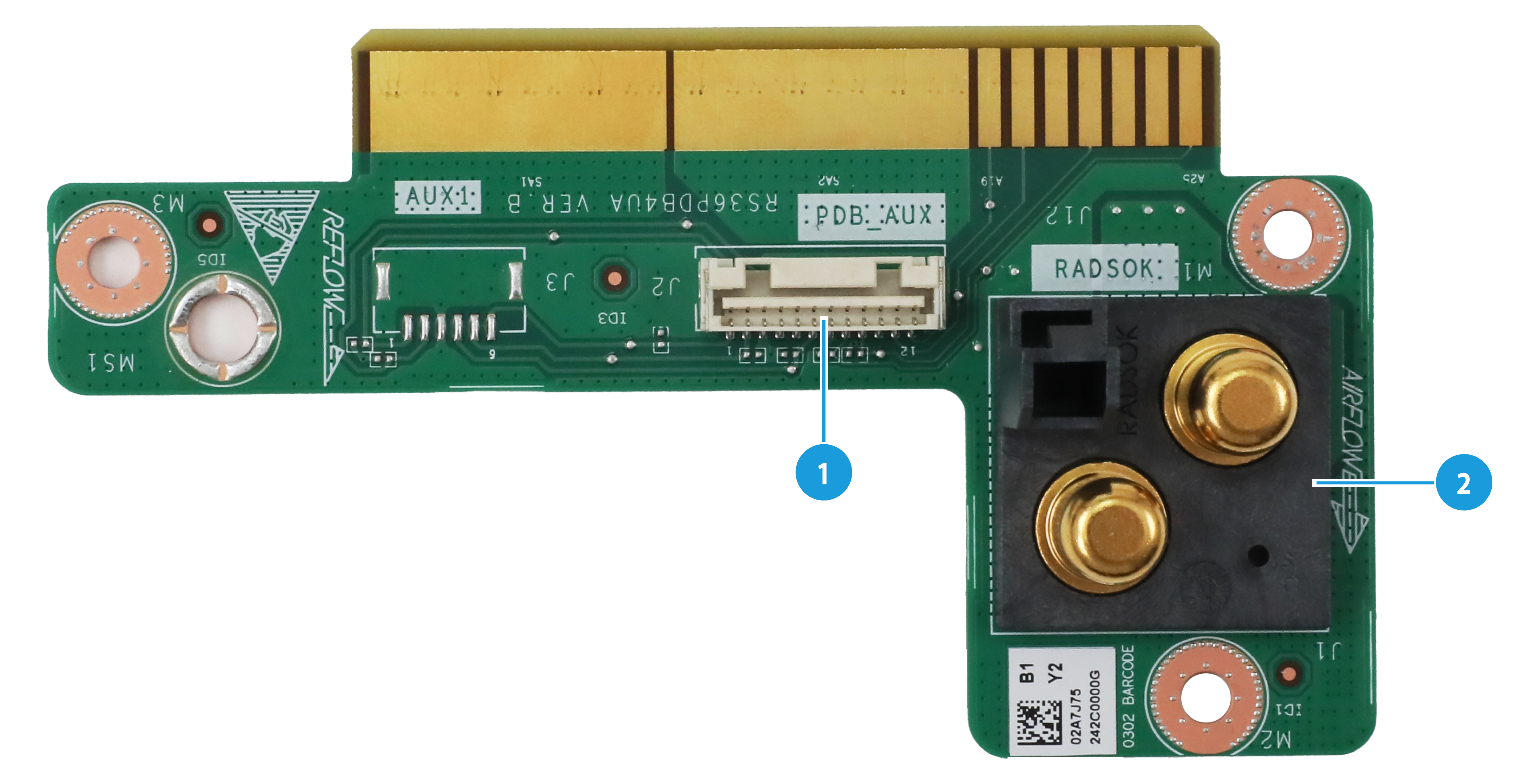
Table 23 Upper power distribution board components
|
No. |
Specification |
|
1 |
Lower power distribution board PDB AUX signal connector |
|
2 |
Lower power distribution board RADSOK connector |
Lower power distribution board
Figure 25 Lower 3U power distribution board
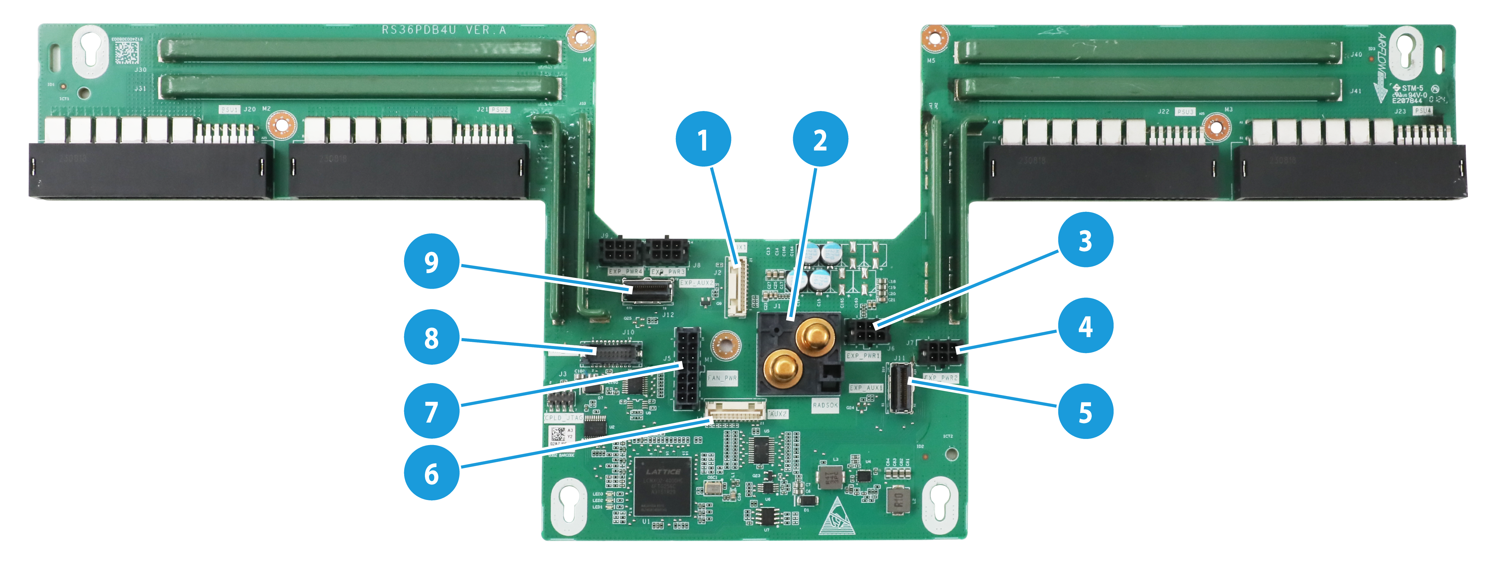
Table 24 Lower power distribution board components
|
No. |
Specification |
|
1 |
System board AUX connector 1 |
|
2 |
Upper power distribution board RADSOK connector |
|
3 |
Expander module PWR connector 1 |
|
4 |
Expander module PWR connector 2 |
|
5 |
Expander module AUX connector 1 |
|
6 |
Upper power distribution board AUX connector 2 |
|
7 |
Front fan PWR connector |
|
8 |
Front fan AUX connector |
|
9 |
Expander module AUX connector 2 |
Fan adapter module
Figure 26 Fan adapter module
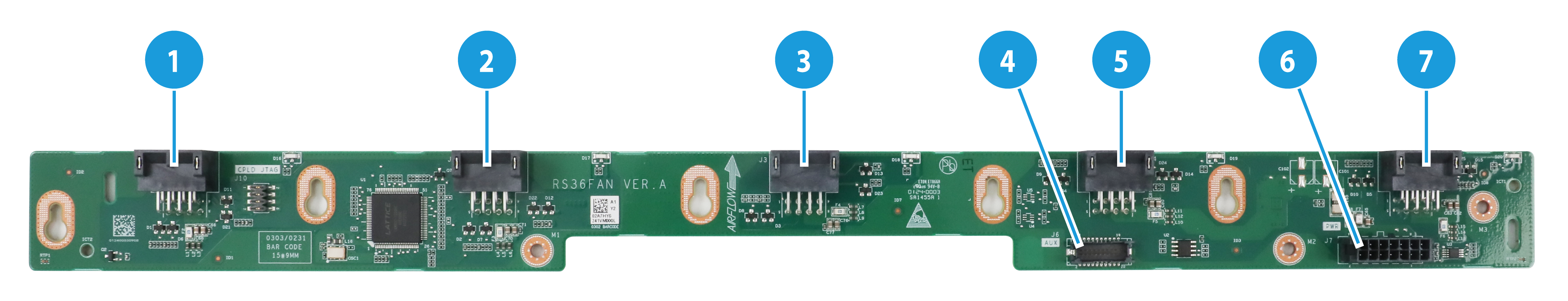
Table 25 Fan adapter module components
|
No. |
Specification |
|
1 |
Front fan connector 1 |
|
2 |
Front fan connector 2 |
|
3 |
Front fan connector 3 |
|
4 |
Front fan AUX connector |
|
5 |
Front fan connector 4 |
|
6 |
Front fan PWR connector |
|
7 |
Front fan connector 5 |
Expander module
Figure 27 Expander module
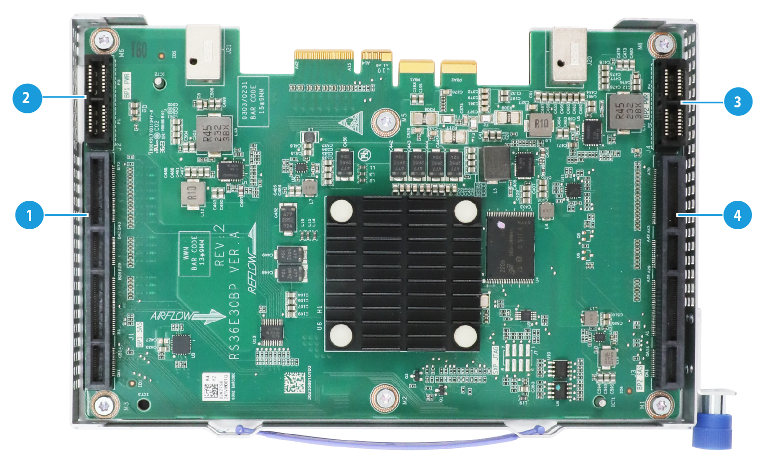
Table 26 Expander module components
|
No. |
Specification |
|
1 |
Expander module SAS connector 1 |
|
2 |
Expander module PWR connector 1 |
|
3 |
Expander module PWR connector 2 |
|
4 |
Expander module SAS connector 2 |
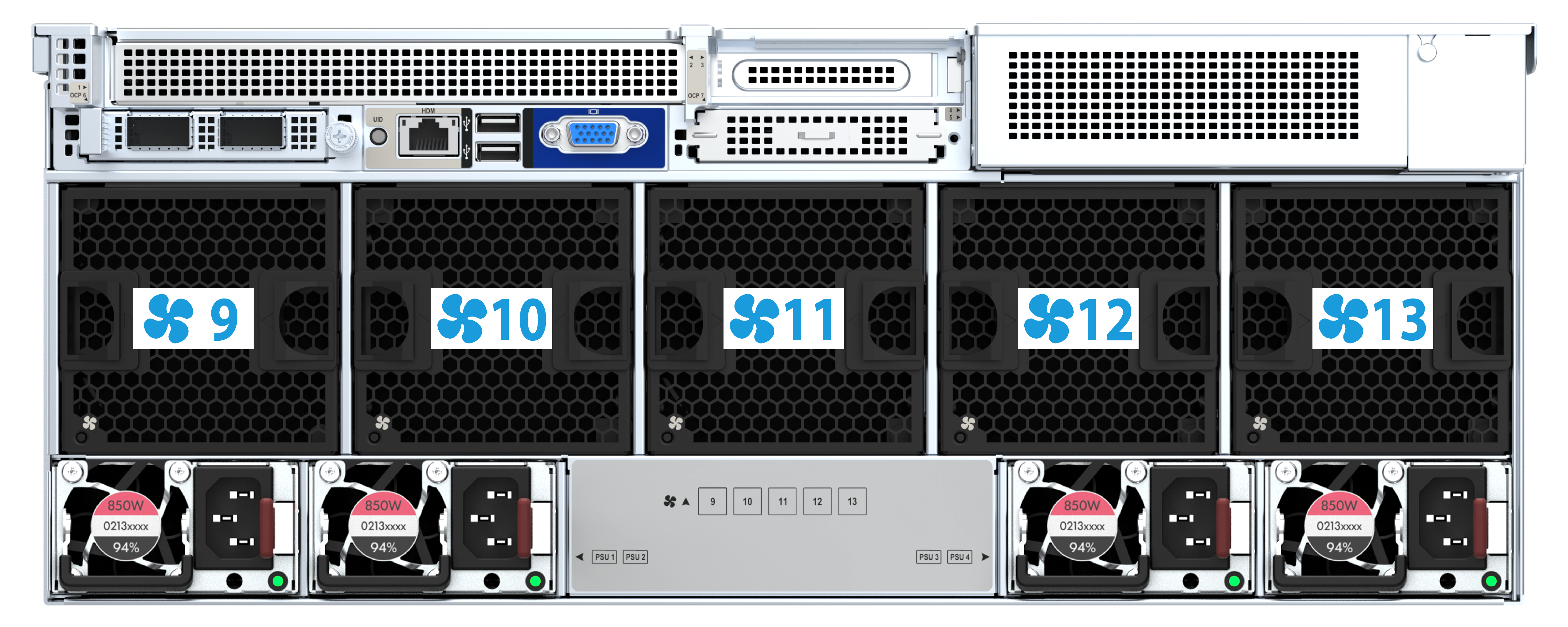
Fans
The server supports up to eight 4056 and five 4U standard hot-swappable fans. Figure 28 and Figure 29 show the fan module layouts. The server supports N+1 fan redundancy, which indicates that the server can operate correctly when a fan fails.
The server supports variable fan speeds, allowing for the fans to automatically adjust their speed based on the actual system temperature. The speed policy balances system cooling and noise, optimizing heat dissipation and reducing noise.
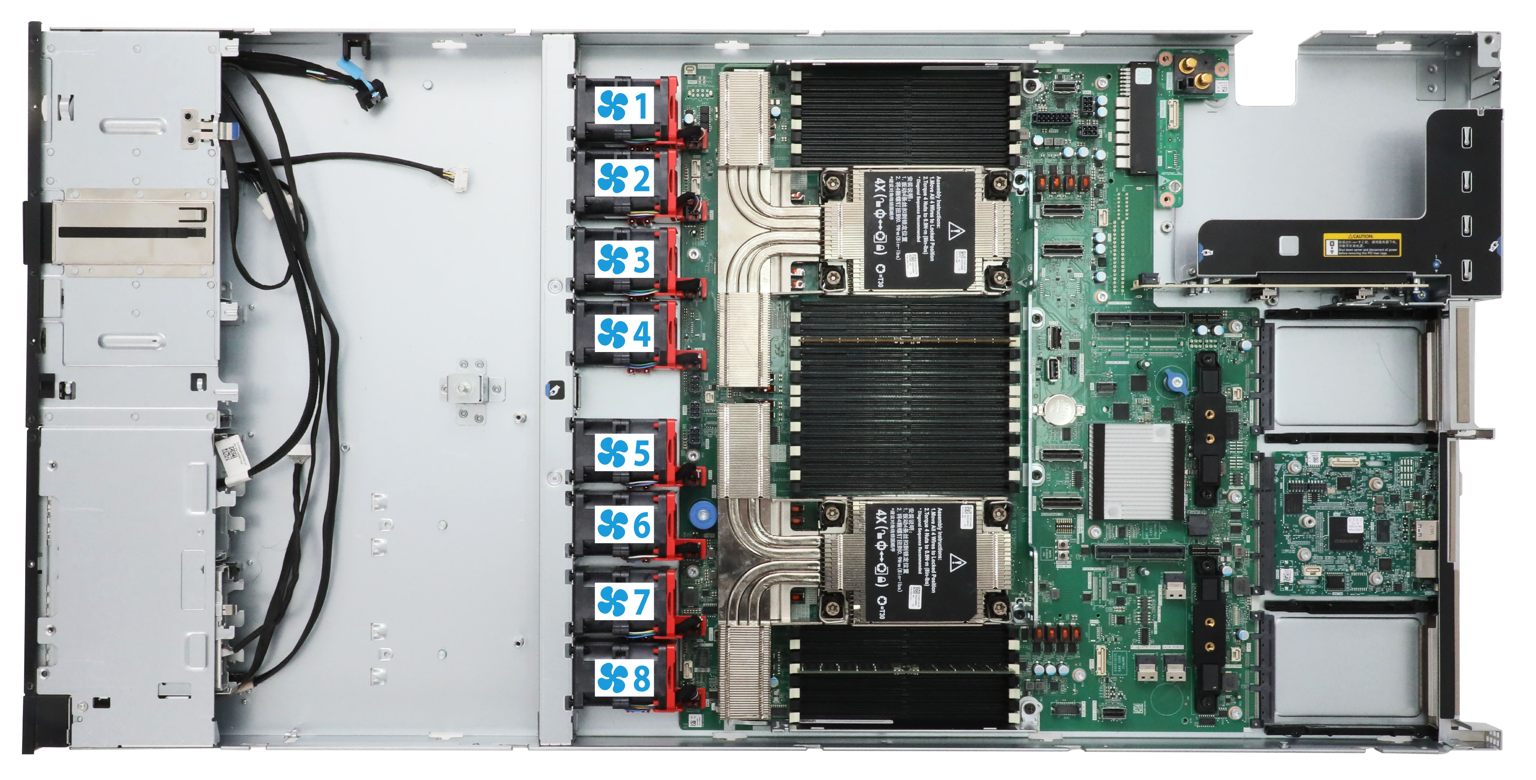
Figure 29 Five 4U standard fans
B/D/F information about the server
The B/D/F information of the server might change with the PCIe card configuration. Users can obtain the B/D/F information of the server through the following ways:
· BIOS serial port logs: If serial port logs have been collected, users can query the B/D/F information of the server by searching the keyword "dumpiio".
· UEFI Shell: Users can obtain the B/D/F information of the server by using the pci command. For details on how to use the pci command, use the help pci command.
· The way to obtain the B/D/F information varies by operating system. The specific ways are as follows:
¡ Linux OS: You can execute the lspci -vvv command to obtain the B/D/F information of the server.
¡ Windows OS: After installing the pciutils package, execute the lspci command to obtain the B/D/F information of the server.
¡ VMware OS: The VMware OS supports the lspci command by default. You can obtain the information by executing the lspci command.
|
|
NOTE: If the operating system does not support the lspci command by default, you can obtain it through the yum source and install the pci-utils package. |
Component installation guidelines
Processors
Installation guidelines
· You can install one or two processors.
· To avoid damage to a processor or the system board, only H3C authorized or professional server engineers can install a processor.
· Make sure the processors on the server are the same model.
· If the model of a processor is U, the processor supports only single-processor operation. For information about processor model suffixes, see "Processor model suffixes."
· The pins in the processor sockets are very fragile and prone to damage. Install a protective cover if a processor socket is empty.
· For the server to operate correctly, make sure processor 1 is in position. For more information about processor locations, see "System board layout."
· To prevent static electricity from damaging the electronic components, wear an ESD wrist strap before operation and ground the other end of the ESD wrist strap.
· To prevent burns caused by the high temperature of the processor heatsink during disassembly, take adequate heat protection measures prior to operation.
Processor model suffixes
If the model of a processor is UN-CPU-INTEL-8490H, the model suffix is H. For more information about the supported processor models, use the Component Compatibility Lookup Tool.
Table 27 describes the suffixes of Intel Eagle Stream processor models.
Table 27 Intel Eagle Stream processor model suffixes and descriptions
|
Processor model suffix |
Description |
Remarks |
|
P |
Cloud–IaaS |
IaaS scenario-based optimization for VM applications requiring high base frequency |
|
V |
Cloud–SaaS |
SaaS scenario-based optimization for high-density and low-power consumption VM applications |
|
M |
Media Transcode |
Media scenario-based optimization |
|
H |
DB and Analytics |
Database and analytics optimization |
|
Y |
Speed Select Technology – Performance Profile |
Supports Intel SST technology for configuring the number of cores and core frequency |
|
N |
Network/5G/Edge(High TPT/Low Latency) |
Support network/5G/Edge (high throughput/low latency) services |
|
S |
Storage & HCI |
Support for storage and hyper-converged architecture |
|
T |
Long-life Use/High Tcase |
Support high-lifetime/ high-temperature specifications |
|
U |
1-Socket |
Support only one-processor operation |
|
Q |
Liquid cooling |
Liquid-cooled dedicated processor model |
|
This table is for reference only. For more information, see the Intel official website. |
||
Memory
The server supports DDR5 DIMMs.
Concepts
DDR
DDR5 DIMMs can perform parity check on addresses. The data in DDR5 will be lost in the event of an unexpected power failure of the server system.
Rank
The number of ranks is usually 1, 2, 4, or 8, generally abbreviated as 1R/SR, 2R, 4R, 8R, or single-rank, dual-rank, quad-rank, or 8-rank. The server supports single-rank and dual-rank.
· A 1R DIMM has a set of DIMM chips that will be accessed when data is written to or read from the DIMM.
· A 2R DIMM is equivalent to a module containing two 1R DIMMs, but only one rank can be accessed at a time.
· A 4R DIMM is equivalent to a module containing two 2R DIMMs, but only one rank can be accessed at a time.
· A 8R DIMM is equivalent to a module containing two 4R DIMMs, but only one rank can be accessed at a time.
When writing or reading data in a DIMM, the server memory control subsystem will select the correct rank from the DIMM.
DIMM specifications
DIMM specifications can be identified by the label on it. The memory labels across different DDR generations have similar meanings. This section uses DDR5 memory as an example to explain the significance of each character in the label.
Figure 30 DIMM identification
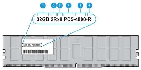
Table 28 Description of DIMM identification
|
No. |
Description |
Definition |
|
1 |
Capacity |
· 16GB · 32GB · 64GB · 96GB |
|
2 |
Number of ranks |
· 1R = The number of ranks is 1. · 2R = The number of ranks is 2. |
|
3 |
Data width |
· x4 = 4-bit · x8 = 8-bit |
|
4 |
DIMM generation |
DDR5 |
|
5 |
DIMM equivalent rate |
· 4800: 4800MHz · 5600: 5600MHz |
|
6 |
DIMM type |
· R = RDIMM · L = LRDIMM |
DIMM mode
The server supports the following DIMM modes to protect the data in the DIMM.
|
|
NOTE: Independent Mode is the default mode and is not available on the BIOS interface. |
· Independent Mode (default)
· Mirror Mode
Independent Mode
Standard ECC can correct 1-bit memory errors and detects multi-bit memory errors. When standard ECC detects multi-bit errors, it informs the server and stops the server. Together with other RAS technologies, independent mode can correct 1-bit or 4-bit memory errors (when the errors are located on the same DDR5 on the DIMM). Independent mode can provide more powerful protection and correct memory errors that cannot be corrected by standard ECC and cause the server to shut down.
Mirror Mode
Mirror mode uses a portion of the system memory for mirroring, to improve system stability and prevent uncorrectable memory errors that cause server downtime. When an uncorrectable error is detected in a memory channel, the blade server will fetch data from the mirrored memory. Mirroring mode supports both full and partial mirroring. In full mirroring, half of the system memory is used as mirrored memory. Partial mirroring allows flexible configuration of mirrored memory capacity.
Installation guidelines
The server supports one or two processors, each processor supports eight channels, and each channel supports two DIMMs, that is, one processor supports 16 DIMMs and two processors support 32 DIMMs.
DIMM and processor compatibility
Table 29 describes the DIMM and processor compatibility.
Table 29 DIMM and processor compatibility
|
Processor type |
Processor-compatible memory type@frequency |
Max memory size per processor |
|
Sapphire Rapids |
DDR5 @4800MHz |
6TB |
|
Emerald Rapids |
DDR5 @5600MHz |
4TB |
Memory operating frequency
|
|
NOTE: To obtain the memory frequency and maximum memory frequency supported by a specific processor, use the component compatibility lookup tool at http://www.h3c.com/en/home/qr/default.htm?id=66. You can query the memory frequency by selecting Memory Module and query the maximum supported memory frequency by selecting Processor. |
The actual operating memory frequency is equal to the lesser of the memory frequency or the maximum memory frequency supported by the processors. For example, if the memory frequency is 4400 MHz and the maximum memory frequency supported by processors is 4800 MHz, the actual operating memory frequency is 4400 MHz.
The number of DIMMs per channel (DPC) affects the memory operating frequency. For more information, see Table 30.
Table 30 Operating DIMM frequency with different DPC configuration
|
Processor type |
DDR5 DIMM frequency |
DPC configuration |
Operating DIMM frequency |
|
Sapphire Rapids |
4800MHz |
1DPC |
4800MHz |
|
2DPC |
4400MHz |
||
|
Emerald Rapids |
5600MHz |
1DPC |
5600MHz |
|
2DPC |
4400MHz |
Installation guidelines
· Make sure the corresponding processors for DIMMs are present before powering on the server.
· As a best practice, install DDR5 DIMMs that have the same product code and DIMM specification (type, capacity, rank, and frequency). For information about DIMM product codes, use the component compatibility lookup tool at http://www.h3c.com/en/home/qr/default.htm?id=66. To install components or replace faulty DIMMs of other specifications, contact Technical Support.
· In addition to the above guidelines, different DIMM modes have their own specific guidelines, as described in Table 31. If the DIMM configuration does not meet the requirements for the configured memory mode, the system uses the default memory mode (Independent mode).
Table 31 DIMM population requirements
|
Memory mode |
DIMM population requirements |
|
Independent mode (default) |
Follow the following installation guidelines: · If one processor is present, see Figure 31. · If two processors are present, see Figure 32 and Figure 33. |
|
Mirror Mode |
· If one processor is present, this mode is supported only when 8 or 16 DIMMs are installed. · If two processors are present, this mode is supported only when 16 or 32 DIMMs are installed. · If one processor is present, see Figure 31. · If two processors are present, see Figure 32 and Figure 33. |
|
|
NOTE: In Figure 31, Figure 32, and Figure 33, the black DIMM slots (for example, the F1 slot) are grey colored, and the white DIMM slots (for example, the F0 slot) are not colored. |
Figure 31 DIMM population schemes for one processor

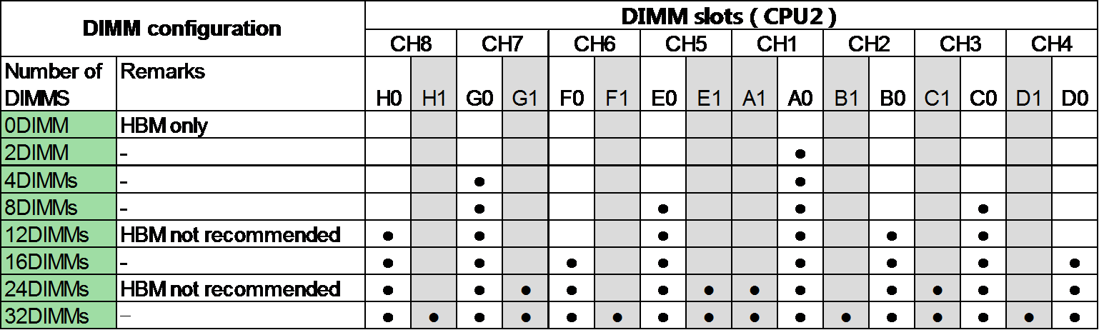
Figure 32 DIMM population schemes for two processors (1)
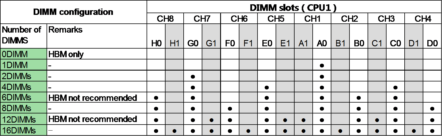
Figure 33 DIMM population schemes for two processors (2)
SAS/SATA drives
|
|
IMPORTANT: Using a drive in multiple RAID arrays complicates maintenance and affects RAID performance. As a best practice for HDD drives to be recognized by the system, when you hot swap HDD drives, replace them one by one, and make sure two drives are replaced with an interval of a minimum of 30 seconds. |
· The drives are hot swappable in the following scenarios:
¡ SAS/SATA drives managed by a storage controller support hot swapping only after the device enters the BIOS or operating system.
¡ SATA drives managed by the embedded VROC controller support hot swapping only after the device enters the operating system.
· As a best practice, install drives that do not contain RAID information.
· To avoid RAID performance degradation and RAID creation failures, make sure all drives in the RAID are the same type (HDDs or SSDs) and have the same connector type (SAS or SATA).
· For efficient use of storage, use drives that have the same capacity to build a RAID. If the drives have different capacities, the lowest capacity is used across all drives in the RAID.
NVMe drives
· NVMe drives are hot swappable in some operating systems.
· As a best practice, install drives that do not contain RAID information.
· For efficient use of storage, use drives that have the same capacity to build a RAID. If the drives have different capacities, the lowest capacity is used across all drives in the RAID. For NVMe drives with a larger capacity, their excess capacity cannot be used to configure the current RAID or other RAIDs.
· NVMe drives support hot swapping. Insert a drive steadily without pauses to prevent the operating system from being stuck or restarted.
· Whether or not NVMe drives support hot swapping and managed hot removal depends on the operating system. You can query the compatibility information through H3C Servers Compatibility Lookup Tools.
· Do not hot swap multiple NVMe drives at the same time. As a best practice, hot swap NVMe drives one after another at intervals longer than 30 seconds for the operating system to identify the installed or removed NVMe drive. If you insert multiple NVMe drives in a short period of time, the system might fail to identify the drives.
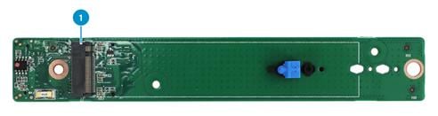
M.2 SSDs
An M.2 SSD is installed in the server through an M.2 SSD adapter. An adapter can be installed at the front or rear of the chassis. Depending on the installation position of the adapter, M.2 SSDs can be classified into front and rear types.
Front SATA/NVMe M.2 SSDs
· A front M.2 SSD adapter is installed at the front of the chassis, between the drive backplane and fan. It supports SATA and NVMe M.2 SSDs. An M.2 adapter is connected to the system board through a data cable. For more information about cabling, see the cabling description.
· You can install two SATA/NVMe M.2 SSDs in a front M.2 SSD adapter to set up RAID 0 or RAID 1. To ensure RAID reliability, use SATA/NVMe M.2 SSDs of the same model.
· As a best practice, use an SATA/NVMe M.2 SSD for operating system installation.
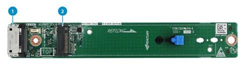
Figure 34 Front side of the M.2 SSD adapter
|
(1) Data cable connector |
(2) M.2 SSD slot 1 |
Figure 35 Rear side of the M.2 SSD adapter
|
(1) M.2 SSD slot 2 |
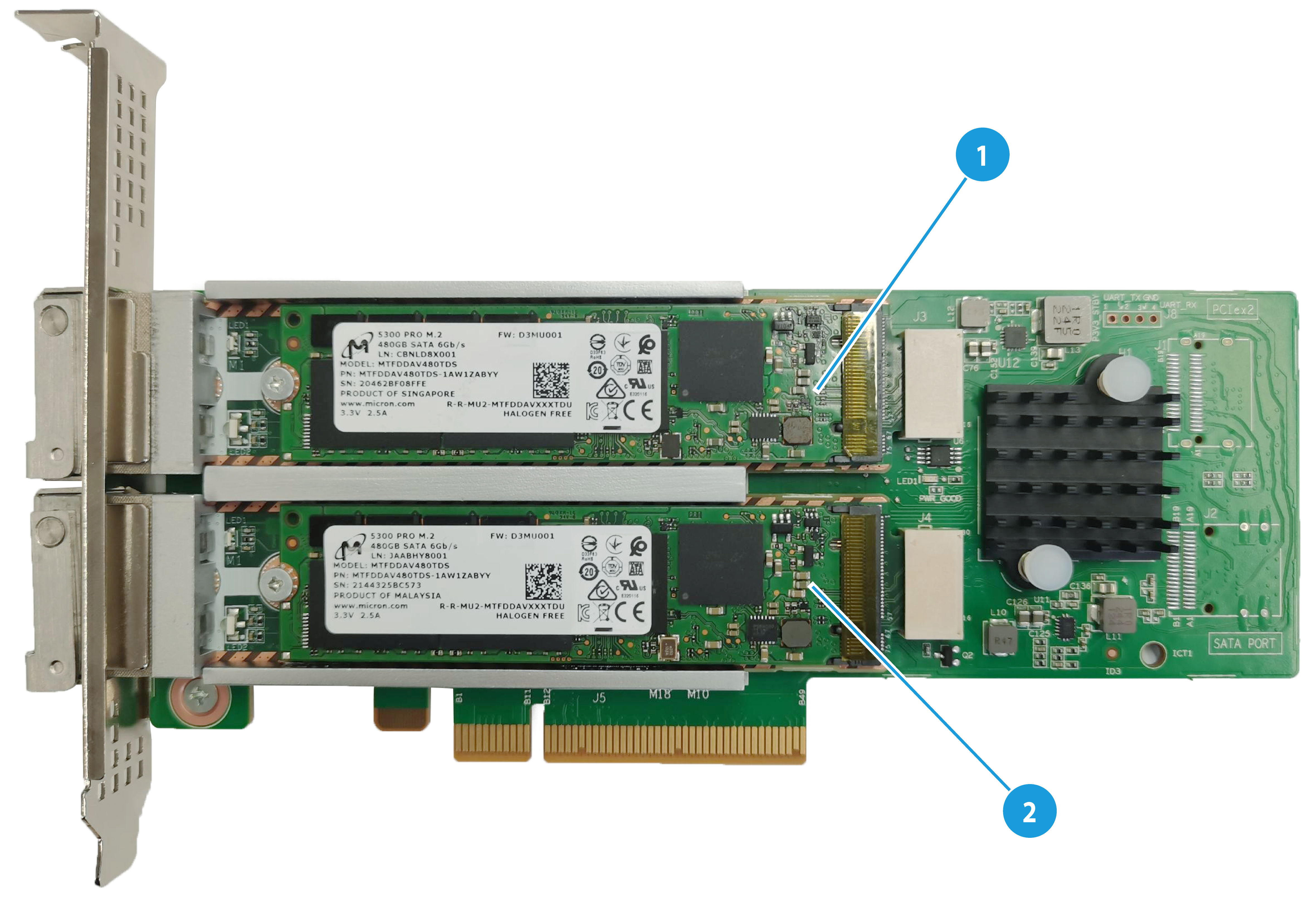
Rear NVMe M.2 SSDs
· A rear NVMe M.2 SSD adapter (model: RAID-MARVELL-SANTACRUZ-LP-2i) is installed at the rear of the chassis. It supports a maximum of two NVMe M.2 SSDs.
· You can install two NVMe M.2 SSDs in a rear NVMe M.2 SSD adapter to set up RAID 0 or RAID 1. To ensure RAID reliability, use NVMe M.2 SSDs of the same model. For more information about RAID configuration, see the storage controller user guide.
· A rear NVMe M.2 adapter can be installed to any PCIe slot with x8 or above bus bandwidth.
· As a best practice, use an NVMe M.2 SSD for operating system installation.
Figure 36 Rear NVMe M.2 SSD adapter
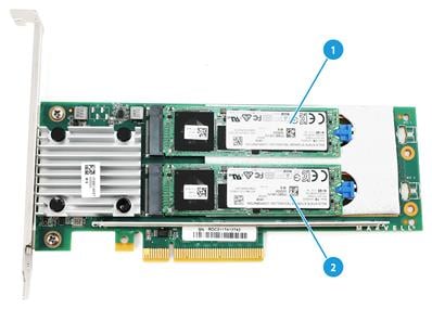
|
(1) NVMe M.2 SSD slot 1 |
(2) NVMe M.2 SSD slot 2 |
Rear SATA M.2 RAID controller
· A rear SATA M.2 RAID controller (model: RAID-MARVELL-M.2) is installed at the rear of the chassis. It supports a maximum of two SATA M.2 SSDs.
· You can install two SATA M.2 SSDs in a rear M.2 SSD RAID controller to set up RAID 0 or RAID 1. To ensure RAID reliability, use SATA M.2 SSDs of the same model.
· For more information about RAID configuration, see the storage controller user guide.
· A rear SATA M.2 RAID controller can be installed to any PCIe slot with x8 or above bus bandwidth.
· As a best practice, use an SATA M.2 SSD for operating system installation.
Figure 37 SATA M.2 RAID controller
|
(1) SATA M.2 RAID controller drive slot 1 |
(2) SATA M.2 RAID controller drive slot 2 |
Server management module
The server management module is installed on the system board to provide I/O connectors and HDM out-of-band features for the server.
Figure 38 Server management module
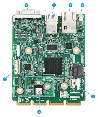
Table 32 Server management module description
|
No. |
Description |
|
1 |
VGA connector |
|
2 |
Two USB 3.0 connectors |
|
3 |
HDM dedicated management interface |
|
4 |
UID LED |
|
5 |
Serial port |
|
6 |
iFIST mezzanine board |
|
7 |
NCSI connector |
Serial & DSD module
The serial & DSD module can be installed in the slot on the server rear panel. For more information, see "Rear panel." The module supports two SD cards, forming RAID 1 by default.
|
|
NOTE: As a best practice to avoid waste of the SD card storage space, install two SD cards with the same capacity. |
Figure 39 Serial & DSD module
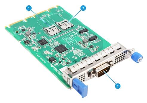
Table 33 Serial & DSD module description
|
No. |
Description |
|
1 |
SD card slot 1 |
|
2 |
SD card slot 2 |
|
3 |
Serial port |
Riser cards and PCIe modules
PCIe card sizes
Table 34 PCIe card sizes
|
Abbreviated name |
Full name |
|
LP card |
Low Profile card |
|
FHHL card |
Full Height, Half Length card |
|
FHFL card |
Full Height, Full Length card |
|
HHHL card |
Half Height, Half Length card |
|
HHFL card |
Half Height, Full Length card |
Riser card and PCIe module compatibility
Guidelines
· If a processor is absent, the PCIe slot connected to it is unavailable.
· To view the position of a PCIe riser slot on the system board, see "System board layout." For information about the PCIe slots on the riser card, see "Riser cards."
· You can install a PCIe module in a PCIe slot for a larger-sized PCIe module. For example, an LP PCIe module can be installed in a slot for an FHFL PCIe module.
· A PCIe slot supports components with a maximum power consumption of 75 W. To install components with higher power consumption, use a power cable.
· PCIe5.0 x8 (for example):
¡ PCIe5.0: Fifth-generation signal rate.
¡ x8: Compatible bus bandwidth, including x8, x4, x2, and x1.
· x8 in x8 SlimSAS connector represents the bus bandwidth.
· By default, the width of a standard PCIe slot connector is X16.
Table 35 Riser card and PCIe module compatibility
|
Riser card model |
Riser card installation location |
PCIe slot number and cable expander connector on riser card |
PCIe slot or connector description |
PCIe devices supported by PCIe slot or connector |
PCIe power supply capability |
Secondary processor |
|
|
RC-2FHFL-1U-SW-G6 |
PCIe riser connector 1 |
PCIe slot number |
slot 1 |
PCIe5.0 x16 |
FHHL card |
75W |
Processor 1 |
|
slot 2 |
PCIe5.0 x16 |
LP modules |
75W |
Processor 1 |
|||
|
RC-1HHHL-R2-1U-SW |
PCIe riser connector 2 |
PCIe slot number |
slot 3 |
PCIe5.0 x16 |
HHHL card |
75W |
CPU 2 |
|
RC-2FHHL-1U |
PCIe riser connector 3 |
PCIe slot number |
slot 4 |
PCIe5.0 x16 |
FHHL card |
75W |
Processor 1 |
|
slot 5 |
PCIe5.0 x8 |
FHHL card |
75W |
CPU 2 |
|||
|
RC-1HHHL-R4-1U-X16-G5 |
PCIe riser connector 4 |
PCIe slot number |
slot 4 |
PCIe4.0 x16 |
HHHL card |
75W |
Processor 1 |
|
Cable expander connector |
SlimSAS connector 1 |
x8 SlimSAS connector |
Connects to the MCIO connector C1-P4A on the system board and provides an x16 PCIe link for slot 4 together with the other x8 SlimSAS connector |
N/A |
Processor 1 |
||
|
SlimSAS connector 2 |
x8 SlimSAS connector |
Connects to the MCIO connector C1-P4C on the system board and provides an x16 PCIe link for slot 4 together with the other x8 SlimSAS connector |
N/A |
Processor 1 |
|||
Storage controller and power fail safeguard module
Storage controller
Table 36 Storage controller types
|
Type |
Installation position |
|
Embedded VROC storage controller |
Embedded on the system board, requiring no installation. |
|
Standard storage controller |
Installed to a PCIe slot on the system board through a riser card. |
Table 37 shows the embedded VROC array controller specifications. For the specifications of other storage controllers, use the server-compatible parts query tool on the official website.
Table 37 Embedded VROC array controller specifications
|
Item |
Specifications |
|
Model |
Embedded VROC storage controller |
|
Number of connectors |
12 embedded SATA connectors |
|
Connector type |
The system board provides one x8 SlimSAS connector and one x4 SlimSAS connector. |
|
Connector features |
6.0Gb/s SATA 3.0 connector Drive hot swapping |
|
PCIe connector |
PCIe2.0 x4 width |
|
RAID level |
RAID 0/1/5/10 |
|
Position |
Embedded in system board PCH |
|
Cache |
None |
|
Flash |
None |
|
Power fail safeguard |
Not supported |
|
Supercapacitor connector |
None |
|
Firmware update |
Update with BIOS |
Power fail safeguard module
A power fail safeguard module provides a flash card and a supercapacitor. The server supports two types of flash cards: flash cards that require installation onto a storage controller and flash cards embedded in a storage controller. The latter ones do not require installation.
In the event of an unexpected power failure of the server system, the supercapacitor can power the flash card for more than 20 seconds, during which the cached data is transferred from the DDR memory of the storage controller to the flash card. Since the flash card is a non-volatile storage medium, it enables permanent storage of cached data or until the server system is powered up and the storage controller retrieves such data.
|
|
NOTE: After the supercapacitor is installed, the power might be low. No action is required at this time. The internal circuitry will automatically charge and enable the supercapacitor when the server is powered on. You can query the supercapacitor status through HDM or BIOS. |
Supercapacitor lifespan guidelines:
· A supercapacitor has a lifespan of 3 to 5 years.
· If the lifespan of a supercapacitor expires, a supercapacitor exception might occur. The system notifies users of supercapacitor exceptions by using the following methods:
¡ For a PMC supercapacitor, the status of the flash card will become Abnormal_status code. You can check the status code to identify the exception. For more information, see the HDM2 online help.
¡ For an LSI supercapacitor, the status of the flash card will become Abnormal.
¡ HDM will generate SDS log records. For details on how to query the SDS log, see the HDM2 online help.
· For the power fail safeguard module to take effect, replace the supercapacitor before its lifespan expires.
|
|
NOTE: After supercapacitor replacement, verify that cache related settings are enabled for logical drives. For more information, see the HDM2 online help. |
Guidelines
· When you install storage controllers, follow these restrictions and guidelines:
¡ Make sure the storage controllers are of the same vendor (PMC or LSI). For information about compatible storage controllers and their vendors, use the component compatibility lookup tool.
¡ Install a storage controller to the following slots in descending order or priority: slot 3, slot 6, slot 1, slot 4, slot 2, slot 5, slot 7, slot 8. To view the slot positions, see "Rear panel."
¡ When you install multiple storage controllers, controllers in slots of smaller numbers must be connected to drive backplanes with smaller bays. Controllers in slots of larger numbers must be connected to drive backplanes with larger bays. For supported bay positions, see "Front panel."
¡ When you install two storage controllers on the front and rear drive backplanes, connect the controller in the slot with smaller number to the rear drive backplane, and connect the controller in the slot with larger number to the front drive backplane.
¡ When the front and rear drive backplanes are connected to the same storage controller, connect the port with smaller number on the controller to the rear drive backplane, and connect the port with larger number on the controller to the front drive backplane.
· Use Table 38 to identify the supercapacitor available for a storage controller.
Table 38 Storage controller and supercapacitor compatibility
|
Storage controller model |
Power fail safeguard module/supercapacitor model |
Supercapacitor installation position |
|
RAID-LSI-9560-LP-8i-4GB |
BAT-LSI-G3-A |
Adjacent to the front riser card or at the chassis rear |
|
RAID-LSI-9560-LP-16i-4GB-M |
||
|
HBA-LSI 9540-LP -8i |
Not supported |
Not supported |
|
HBA-LSI-9500-LP-8i |
||
|
HBA-LSI 9500-LP-16i |
NVMe VROC modules
Table 39 NVMe VROC module specifications
|
Model |
Description |
Supported RAID levels |
|
NVMe-VROC-Key-S |
NVMe VROC module standard edition, supporting all NVMe drives |
RAID 0/1/10 |
|
NVMe-VROC-Key-P |
NVMe VROC module advanced edition, supporting all NVMe drives |
RAID 0/1/5/10 |
Network adapters
· An OCP network adapter can only be installed in the OCP 3.0 network adapter slot on the system board. For information about the slots for OCP network adapters, see "System board layout."
· The OCP network adapters support hot swapping. For operating systems that support hot swapping of OCP network adapters, use the H3C Servers Compatibility Lookup Tools.
· Follow these restrictions and guidelines:
¡ For operating systems that support OCP network adapter hot swapping:
- OCP network adapters installed before the server is powered on support hot swapping. Make sure the replaced network adapter and the newly installed network adapter are the same model. To use an OCP network adapter of another model for replacement, first power off the server.
- OCP network adapters installed after the server is powered on do not support hot swapping. To replace such an OCP network adapter, first power off the server, replace the OCP network adapter, and then power on the server.
¡ For operating systems that do not support OCP network adapter hot swapping, power off the server before replacing the network adapter, and power on the server after the network adapter is replaced successfully.
· To install a standard PCIe network adapter, a riser card is required. For more information, see "Riser card and PCIe module compatibility."
Power supplies
· The power supplies installed on the server must be the same model. If they differ in model, HDM will generate a major alarm.
· The power supplies are hot swappable.
· To avoid damage to hardware, use only H3C approved power supplies.
· The server supports 1+1 or 2+2 power supply redundancy.
· The system provides an overtemperature mechanism for power supplies. The power supplies automatically turn off when they encounter an overtemperature situation and automatically turn on when the overtemperature situation is removed.
For more information about the specifications of power supplies, see the power supply manuals for them.
Fans
· The fan modules are hot swappable and support N+1 redundancy.
· The server must be fully configured with fan modules.
Installing or removing the server
This section describes the steps for installing and removing the server.
Installation flowchart
Figure 40 Installation flowchart
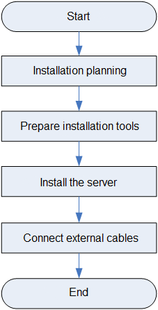
Installation planning
Before installing the server, plan and prepare the physical environment for optimal operation, including space, ventilation, temperature, humidity, cleanliness, altitude, and grounding.
Rack requirements
The server is 4U high and has a depth of 900 mm (35.43 in). The rack for installing the server must meet the following requirements:
· A standard 19-inch rack.
· A minimum of 1200 mm (47.24 in) in depth as a best practice. For installation requirements for different rack depth, see Table 40. As a best practice to avoid installation failures, contact Technical Support to perform onsite survey before the installation.
· A clearance of more than 75 mm (2.95 in) between the rack front posts and the front rack door.
· Table 40Figure 41 shows the installation recommendations for a 1200 mm deep rack.
Table 40 Installation requirements for different rack depths
|
Rack depth |
Installation requirements |
|
1000 mm |
· The H3C cable management arm (CMA) is not supported. · The slide rails and PDUs might hinder each other. Perform onsite survey to determine the PDU installation location and the proper PDUs. If the PDUs hinder the installation and movement of the slide rails anyway, use other methods to support the server, a tray for example. · A clearance of 60 mm (2.36 in) is reserved from the server rear to the rear rack door for cabling. |
|
1100 mm |
Make sure the CMA does not hinder PDU installation at the server rear before installing the CMA. If the CMA hinders PDU installation, use a deeper rack or change the installation locations of PDUs. |
|
1200 mm |
Make sure the CMA does not hinder PDU installation or cabling. If the CMA hinders PDU installation or cabling, change the installation locations of PDUs. |
Figure 41 Installation recommendations for a 1200 mm deep rack (top view)
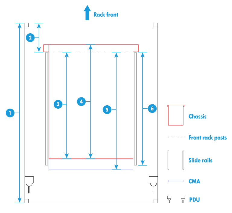
|
Chassis size recommendations and requirements |
|
|
(1) 1200 mm (47.24 in) rack depth |
(2) A minimum of 50 mm (1.97 in) between the front rack posts and the front rack door |
|
· To avoid affecting the server chassis, install power distribution units (PDUs) with the outputs facing backwards. · If you install PDUs with the outputs facing the inside of the server, perform onsite survey to make sure the cables won't affect the server rear. |
|
|
Server size parameters |
|
|
(3) 780 mm (30.71 in) between the front rack posts and the rear of the chassis, including power supply handles at the server rear (not shown in the figure) |
(4) 900 mm (35.43 in) server depth, including chassis ears |
|
(5) 960 mm (37.80 in) between the front rack posts and the CMA |
(6) 860 mm (33.86 in) between the front rack posts and the rear ends of the slide rails |
Airflow direction of the server
Figure 42 Airflow direction of the server
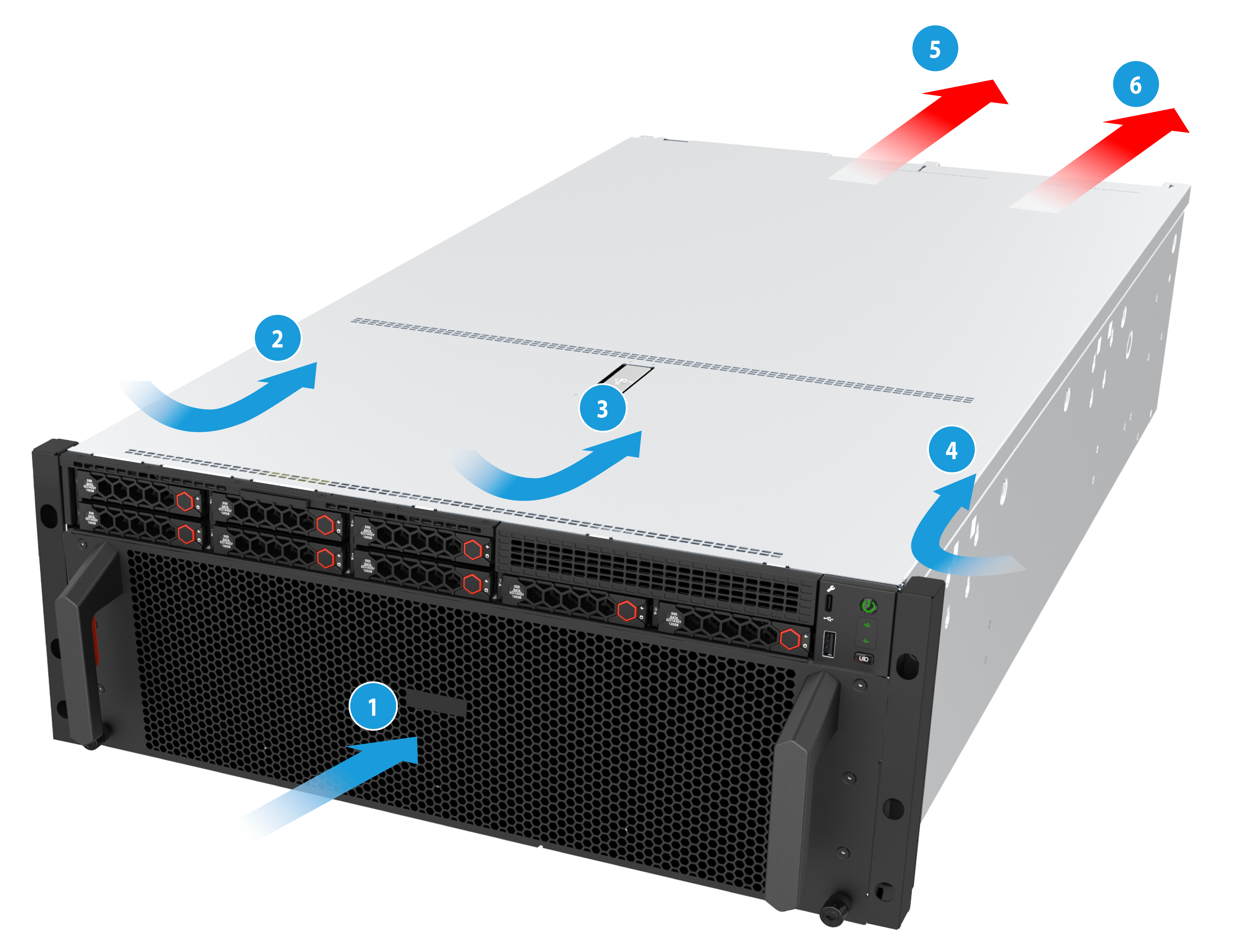
|
(5) to (6) Direction of the airflow out of the chassis |
Temperature and humidity requirements
To ensure correct operation of the server, make sure the equipment room temperature and humidity meet the requirements as described in "Technical specifications."
Equipment room height requirements
To ensure correct operation of the server, make sure the equipment room height meets the requirements as described in "Technical specifications."
Corrosive gas concentration requirements
Corrosive gases can accelerate corrosion and aging of metal components and even cause server failure. Table 41 describes common corrosive gases and their sources.
Table 41 Common corrosive gases and their sources
|
Type |
Sources |
|
Hydrogen sulfide (H2S) |
Geothermal emissions, microbiological activities, fossil fuel processing, wood pulping, sewage treatment. |
|
Sulfur dioxide (SO2) and sulfur trioxide (SO3) |
Combustion of fossil fuel, auto emissions, ore smelting, sulfuric acid manufacture, and tobacco smoke. |
|
Sulphur (S) |
Foundries and sulfur manufacture. |
|
Hydrogen Fluoride (HF) |
Fertilizer manufacture, aluminum manufacture, ceramics manufacture, steel manufacture, electronics device manufacture, and fossil fuel. |
|
Nitrogen Oxide (NOx) |
Automobile emissions, fossil fuel combustion, microbes, and chemical industry. |
|
Ammonia (NH3) |
Microbes, sewage, fertilizer manufacture, and geothermal steam. |
|
Carbonic oxide (CO) |
Combustion, automobile emissions, microbes, and wood pulping. |
|
Chlorine (Cl2) and chlorine dioxide (ClO2) |
Chlorine manufacturing, aluminum manufacturing, zinc manufacturing, and waste decomposition. |
|
Hydrochloric acid (HCl) |
Automobile emissions, combustion, forest fires, and the burning of marine-derived polymers. |
|
Hydrobromic acid (HBr) and hydroiodic acid (HI) |
Automobile emissions. |
|
Ozone (O3) |
Atmospheric photochemical processes (mainly involving nitrogen monoxide and hydrogen peroxide compounds) |
|
Hydrocarbons (CnHn) |
Automobile emissions, tobacco combustion, animal excrement, sewage, and decaying trees |
Requirements for the data center equipment room
As a best practice, make sure the corrosive gas concentration for the data center equipment room meets the requirements of severity level G1 of ANSI/ISA 71.4. The rate of copper corrosion product thickness growth must be less than 300 Å/month, and the rate of silver corrosion product thickness growth must be less than 200 Å/month.
|
|
NOTE: Angstrom (Å) is a metric unit of length equal to one ten-billionth of a meter. |
To meet the copper and silver corrosion rates stated in severity level G1, make sure the corrosive gases in the equipment room do not exceed the concentration limits as shown in Table 42.
Table 42 Corrosive gas concentration limits in the data center equipment room
|
Corrosive gas |
Concentration (ppb) |
|
H2S |
<3 |
|
SO2 and SO3 |
<10 |
|
Cl2 |
<1 |
|
NOx |
<50 |
|
HF |
<1 |
|
NH3 |
<500 |
|
O3 |
<2 |
|
|
NOTE: · In Table 42, part per billion (ppb) is a concentration unit. 1 ppb represents a volume-to-volume ratio of 1 to 1000000000. · The concentration limits in Table 42 are calculated based on the reaction results of the gases in the equipment room with a relative humidity less than 50%. If the relative humidity of the equipment room increases by 10%, the severity level of ANSI/ISA 71.4 to be met must also increase by 1. |
Requirements of corrosive gas concentration vary by server model. For information about the requirements, see the installation guide of the server.
Requirements for the non-data center equipment room
The corrosive gas concentration for the non-data center equipment room must meet the requirements of class 3C2 of IEC 60721-3-3:2002, as shown in Table 43.
Table 43 Corrosive gas concentration limits in the non-data center equipment room
|
Corrosive gas |
Average concentration (mg/m3) |
Maximum concentration (mg/m3) |
|
SO2 |
0.3 |
1.0 |
|
H2S |
0.1 |
0.5 |
|
Cl2 |
0.1 |
0.3 |
|
HCI |
0.1 |
0.5 |
|
HF |
0.01 |
0.03 |
|
NH3 |
1.0 |
3.0 |
|
O3 |
0.05 |
0.1 |
|
NOx |
0.5 |
1.0 |
|
|
NOTE: As a best practice, control the corrosive gas concentrations in the equipment room at their average values. Make sure the corrosive gas concentrations do not exceed 30 minutes per day at their maximum values. |
Requirements of corrosive gas concentration vary by server model. For information about the requirements, see the installation guide of the server.
Guidelines for controlling corrosive gases
· As a best practice, do not build the equipment room in a place with a high concentration of corrosive gases.
· Make sure the equipment room is not connected to sewer, sewage, vertical shaft, or septic tank pipelines and keep it far away from these pipelines. The air inlet of the equipment room must be away from such pollution sources.
· Use environmentally friendly materials to decorate the equipment room. Avoid using organic materials that contains harmful gases, such as sulfur or chlorine-containing insulation cottons, rubber mats, sound-proof cottons, and avoid using plasterboards with high sulfur concentration.
· Place fuel (diesel or gasoline) engines separately. Do not place them in the same equipment room with the device. Make sure the exhausted air of the engines will not flow into the equipment room or towards the air inlet of the air conditioners.
· Place batteries separately. Do not place them in the same room with the device.
· Employ a professional company to monitor and control corrosive gases in the equipment room regularly.
Cleanliness requirements
Dust settling on the device might cause electrostatic adsorption, leading to poor contact in metal connectors or terminals. This not only affects device lifespan but also easily causes communication failures.
Cleanliness requirements for the data center equipment room
The concentration of dust participles in the equipment room must meet the ISO 8 cleanroom standard defined by ISO 14644-1, as described in Table 44.
Table 44 Dust particle concentration limit in the equipment room
|
Particle diameter |
Concentration limit |
Remarks |
|
≥5μm |
≤ 29300 particles/m3 |
Make sure no zinc whiskers are in the equipment room. |
|
≥1μm |
≤ 832000 particles/m3 |
|
|
≥0.5μm |
≤ 3520000 particles/m3 |
Requirements of dust particle concentration vary by server model. For information about the requirements, see the installation guide of the server.
Cleanliness requirements for the non-data center equipment room
The concentration of dust participles (particle diameter ≥ 0.5 µm) must meet the requirement of the GB 50174-2017 standard, which is less than 17600000 particles/m3.
Guidelines for controlling cleanliness
· Keep the equipment room away from pollution sources and do not smoke or eat in the equipment room.
· Use double-layer glass in windows and seal doors and windows with dust-proof rubber strips.
· Use dustproof materials for floors, walls, and ceilings and use matt coating that does not produce powders.
· Keep the equipment room clean and clean the air filters of the rack regularly.
· Wear ESD clothing and shoe covers before entering the equipment room. Keep the ESD clothing and shoe covers clean and replace them frequently.
Grounding requirements
Correctly connecting the server grounding cable is crucial to lightning protection, anti-interference, and ESD prevention. The server can be grounded through the grounding wire of the power supply system and no external grounding cable is required.
Storage requirements
· As a best practice, do not store an HDD for 6 months or more without powering on and using it.
· As a best practice, do not store an SSD, M.2 SSD, or SD card for 3 months or more without powering on and using it. Long unused time increases data loss risks.
· To store the server chassis, or an HDD, SSD, M.2 SSD, or SD card for 3 months or more, power on it every 3 months and run it for a minimum of 2 hours each time.
Installation tools
Table 45 Installation tools
|
Picture |
Name |
Description |
|
|
T25 Torx screwdriver |
Installs or removes screws inside chassis ears. A flat-head screwdriver can also be used for this purpose. |
|
T30 Torx screwdriver |
Installs or removes captive screws on processor heatsinks. |
|
|
T15 Torx screwdriver (shipped with the server) |
Installs or removes screws on the processor system board. |
|
|
T10 Torx screwdriver (shipped with the server) |
Installs or removes screws on riser cards. |
|
|
Flat-head screwdriver |
Replaces system batteries. |
|
|
Phillips screwdriver |
Installs or removes screws on drive carriers. |
|
|
|
Cage nut insertion/extraction tool |
Inserts or extracts the cage nuts in rack posts. |
|
|
Diagonal pliers |
Clips insulating sleeves. |
|
|
Utility knife |
Removes the server's external packaging. |
|
|
Tape measure |
Measures distance. |
|
|
Multimeter |
Measures resistance and voltage. |
|
|
ESD wrist strap |
Prevents ESD when you operate the server. |
|
|
Antistatic gloves |
|
|
|
Antistatic clothing |
|
|
|
Ladder |
Supports high-place operations. |
|
|
Type-C to USB cable USB Wi-Fi module or USB drive |
· Connects to a third-party USB Wi-Fi module for you to access the HDM interface through the HDM mobile client on your mobile device. · Connects to an external USB drive for you to download SDS logs to the USB drive from the HDM interface. NOTE: Support for the USB Wi-Fi module depends on the server model. |
|
|
Interface cable (such as an Ethernet cable or optical fiber) |
Connects the server to an external network. |
|
|
Serial console cable |
Connects the serial connector on the server to a monitor for troubleshooting. |
|
|
Monitor |
Displays the output from the server. |
|
|
Temperature humidity meter |
Displays current temperature and humidity. |
|
|
Oscilloscope |
Displays the variation of voltage over time in waveforms. |


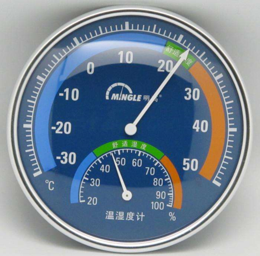
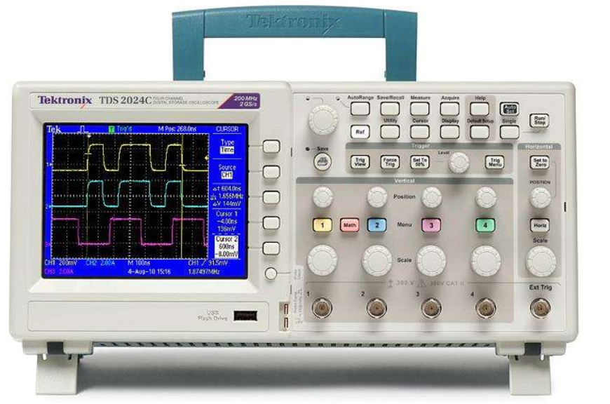
Installing the server
This section describes the steps for installing the server.
(Optional) Installing rails
Install the inner rails to the server and the outer rails to the rack. For information about installing the rails, see the document shipped with the rails.
Installing the server
|
IMPORTANT: When there is no other chassis in the 1U space above, install a clamp on the rear post to prevent the chassis from tilting upward. |
1. As shown in Figure 43, slide the server into the rack. For more information, see the installation guide for the rails.
Figure 43 Sliding the server into the rack
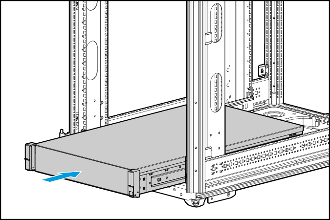
2. Secure the server. As shown in Figure 44:
¡ If an H3C L-shaped rail is installed, lock the side mounting ears into the threaded holes on the L-shaped rail.
¡ If no H3C L-shaped rail is installed, pre-install floating nuts on the cabinet square hole strips, then align the server's side mounting ears with the square hole strips, and tighten the screws with a screwdriver.
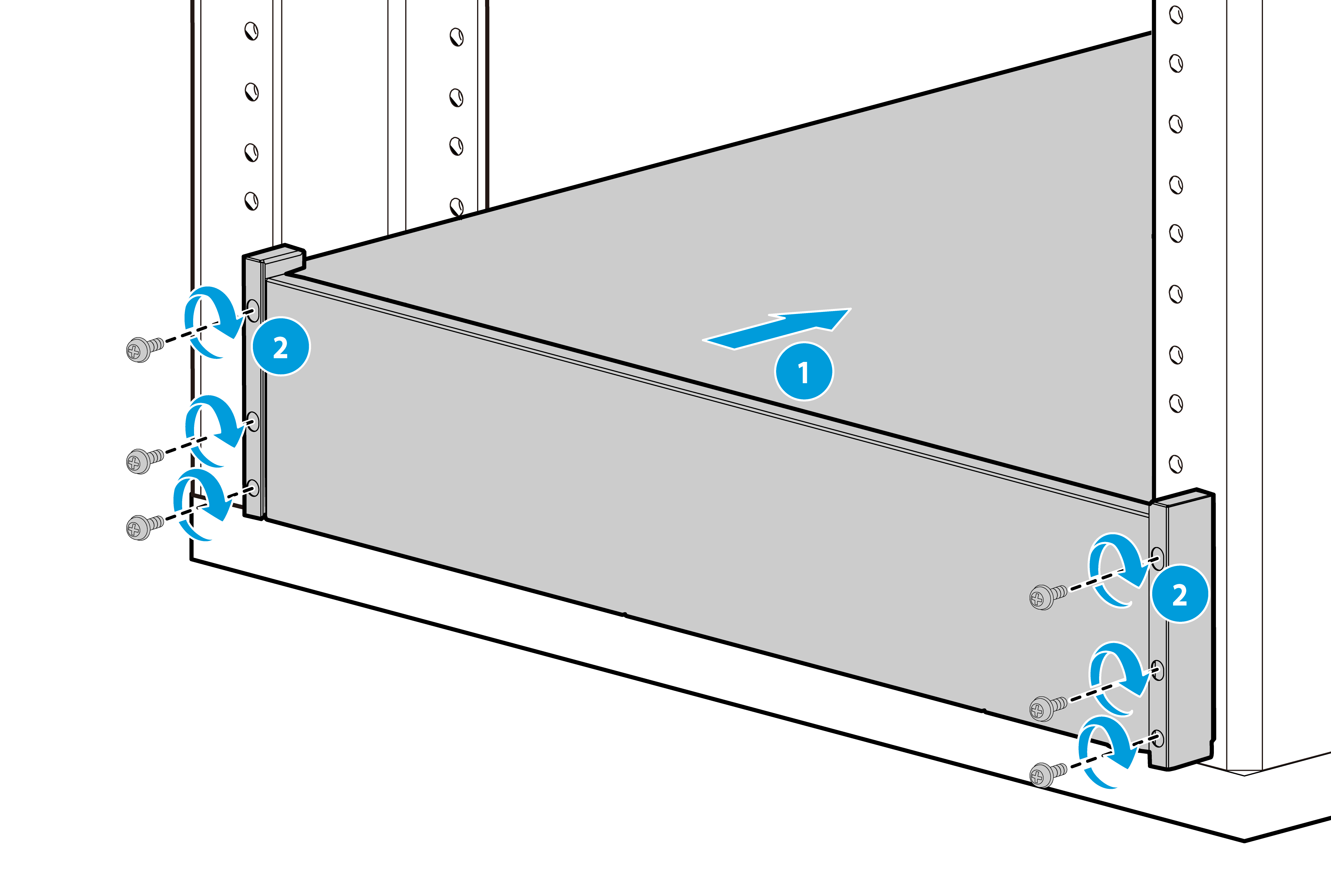
(Optional) Installing cable management brackets
Install cable management brackets if the server is shipped with cable management brackets. For information about how to install cable management brackets, see the installation guide shipped with the brackets.
Connecting external cables
Connecting a mouse, keyboard, and VGA connectors
Scenario
The server provides two DB15 VGA connectors for monitor connection. One is on the front panel and the other is on the rear panel.
The server is not shipped with a standard PS2 mouse or keyboard. You can connect the mouse and keyboard through USB ports. Depending on the interface type of the mouse and keyboard, there are two connection methods:
· Directly connect USB mouse and keyboard using the same method as standard USB cables.
· Connect PS2 mouse and keyboard through a USB-to-PS2 cable.
Procedure
1. As shown in Figure 45, connect one plug of a VGA cable to a VGA connector on the server, and fasten the screws on the plug.
Figure 45 Connecting a VGA cable
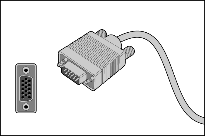
2. Connect the other plug of the VGA cable to the VGA connector on the monitor, and fasten the screws on the plug.
3. Insert the USB connector of the USB-to-PS2 adapter to a USB connector on the server. Then, insert the PS2 connectors of the mouse and keyboard into the PS2 receptacles of the adapter.
Figure 46 Connecting a PS2 mouse and keyboard by using a USB-to-PS2 adapter
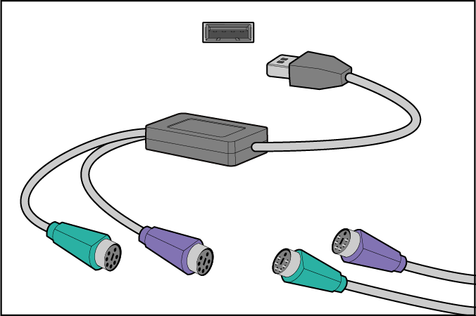
Connecting an Ethernet cable
Scenario
· Set up the server's network environment through the Ethernet interface.
· Access the HDM management interface through the dedicated HDM network interface to manage the server.
· Replace the network cable, because the network is unreachable or the cable length is unsuitable,.
Procedure
1. Identify the network port on the server.
¡ To connect the server to the external network, use the Ethernet port on the network adapter.
¡ To log in to the HDM management interface, use the HDM dedicated network port. For the location of the HDM dedicated network port, see "Rear panel."
If the server is configured with an OCP network adapter, you can also use the HDM shared network port on the OCP network adapter to log in to the HDM management interface. For the location of the OCP network adapter, see "Rear panel."
2. Identify the type of the Ethernet cable.
Verify the connectivity of the cable by using a link tester.
If you are replacing the Ethernet cable, make sure the new cable is the same type or compatible with the old cable.
3. Label the Ethernet cable by filling in the names and numbers of the server and the peer device on the label.
As a best practice, use labels of the same kind for all cables.
If you are replacing the Ethernet cable, label the new cable with the same number as the number of the old cable.
4. Connect one end of the Ethernet cable to the network port on the server and the other end to the peer device.
Figure 47 Connecting an Ethernet cable

5. Verify network connectivity.
After powering on the server, use the ping command to test the network connectivity. If the connection between the server and the peer device fails, verify that the Ethernet cable is securely connected.
6. Secure the Ethernet cable. For information about how to secure cables, see "Securing cables."
Connecting a power cord
Guidelines
· To avoid damage to the device or even bodily injury, use the power cord that ships with the server.
· Before connecting the power cord, make sure the server and components are installed correctly.
Procedure
|
|
NOTE: Multiple types of wire fasteners can be used for securing the power cord. In this procedure, a cable clamp is used. |
1. Insert the power cord plug into the power receptacle of a power supply at the rear panel, as shown in Figure 48.
Figure 48 Connecting a power cord
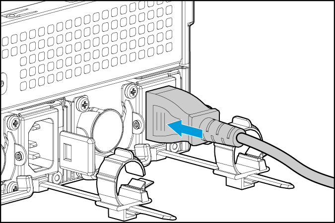
2. Connect the other end of the power cord to the power source, for example, the power strip on the rack.
3. Secure the power cord to avoid unexpected disconnection of the power cord.
a. If the cable clamp is positioned too near the power cord that it blocks the power cord plug connection, press down the tab on the cable mount and slide the clip backward.
Figure 49 Sliding the cable clamp backward
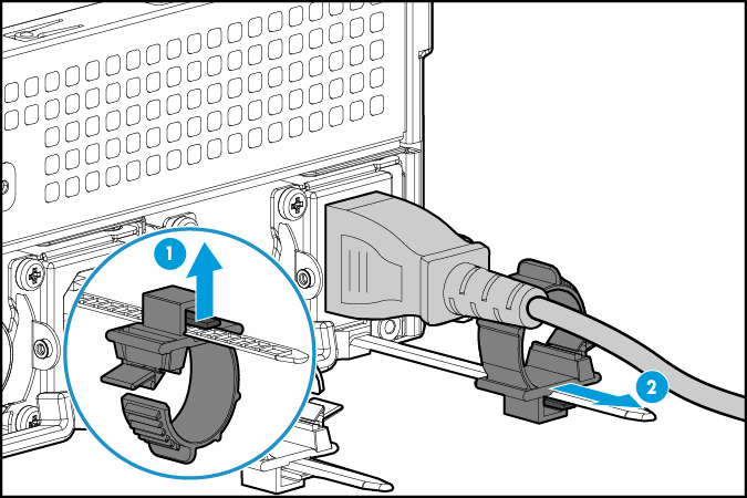
b. Open the cable clamp, place the power cord through the opening in the cable clamp, and then close the cable clamp, as shown by callouts 1, 2, 3, and 4 in Figure 50.
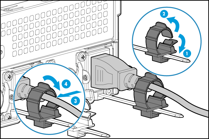
d. Slide the cable clamp forward until it is flush against the edge of the power cord plug, as shown in Figure 51.
Figure 51 Sliding the cable clamp forward
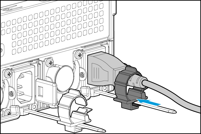
Securing cables
Securing cables to cable management brackets
For information about how to install cable management brackets, see the installation guide shipped with the brackets.
Securing cables to slide rails by using cable straps
|
|
NOTE: You can secure cables to either left slide rails or right slide rails. As a best practice for cable management, secure cables to left slide rails. When multiple cable straps are used in the same rack, stagger the strap location, so that the straps are adjacent to each other when viewed from top to bottom. This positioning will enable the slide rails to slide easily in and out of the rack. |
1. Hold the cables against a slide rail.
2. Wrap the strap around the slide rail and loop the end of the cable strap through the buckle.
3. Dress the cable strap to ensure that the extra length and buckle part of the strap are facing outside of the slide rail.
Figure 52 Securing cables to a slide rail
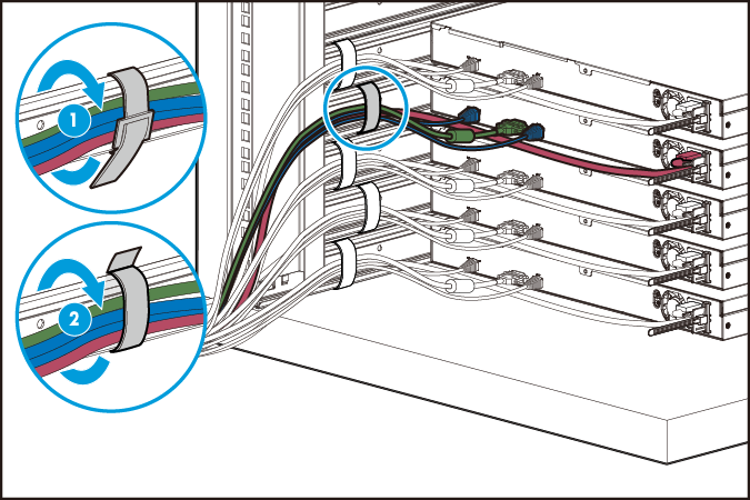
Cabling guidelines
· For heat dissipation, make sure no cables block the inlet or outlet air vents of the fan modules, heatsinks, and PSUs.
· To easily identify ports and connect/disconnect cables, make sure the cables do not cross.
· Label the cables for easy identification of the cables.
· Wrap unused cables onto an appropriate position on the rack.
· To avoid electric shock, fire, or device damage, do not connect telephones or communication devices to the RJ-45 Ethernet ports on the server.
· To avoid damage to cables when pulling the server out of the rack, do not route the cables too tight if you use cable management brackets.
Removing the server
1. Power off the server.
2. Disconnect all peripheral cables from the server.
3. Pull the server out of the rack. As shown in Figure 53:
¡ If an H3C L-shaped rail is installed, unlock the side mounting ears from the threaded holes on the L-shaped rail, and then gently slide the server out of the cabinet along the rail.
¡ If no H3C L-shaped rail is installed, use a screwdriver to loosen the screws inside the server's side mounting ears, and then gently slide the server out of the cabinet along the rail.
Figure 53 Extending the server from the rack
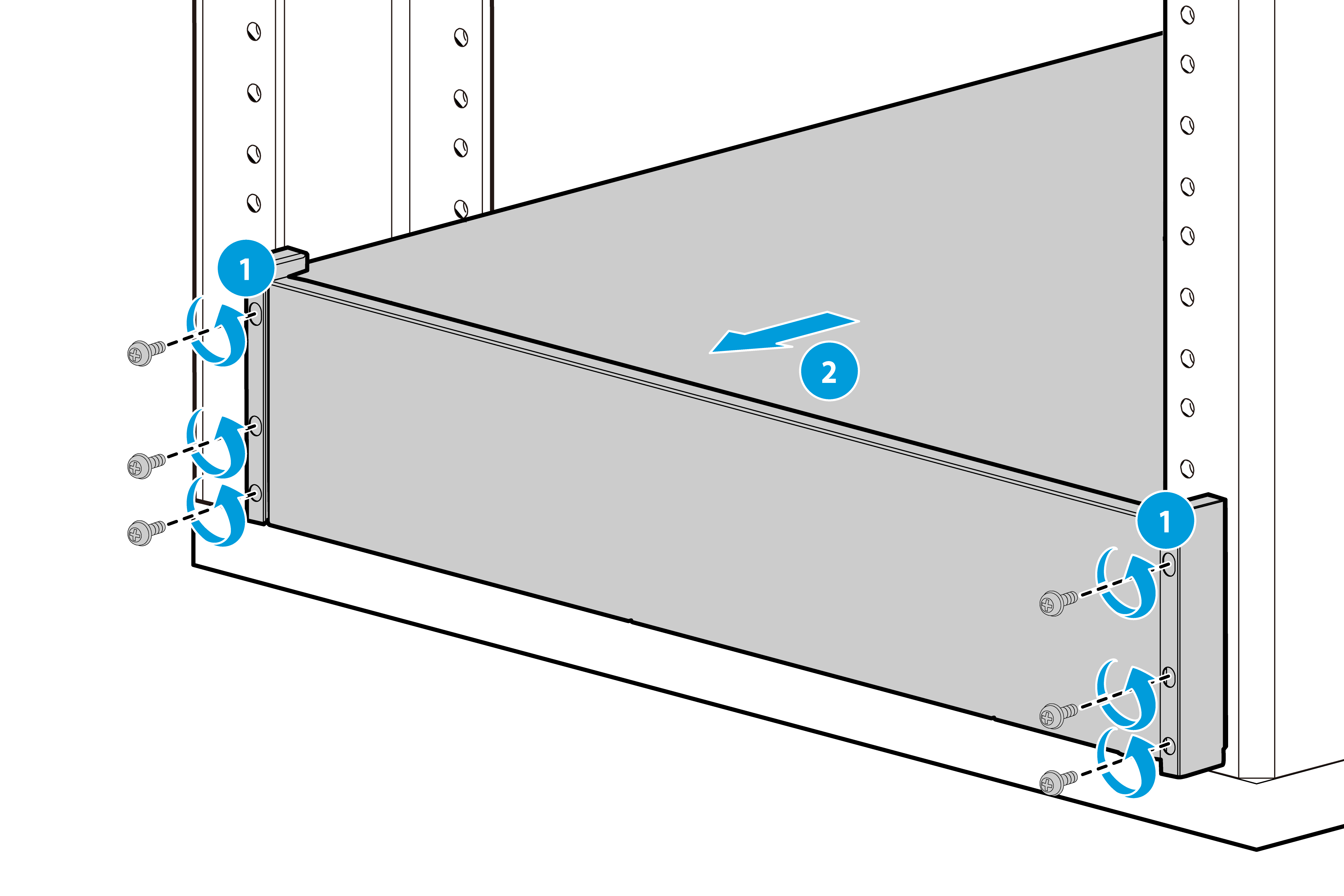
4. Place the server on a clean, stable, anti-static workbench or floor for component installation, replacement, and maintenance.
Powering on and powering off the server
If the server is connected to external storage devices, make sure the server is the first device to power off and the last device to power on. This restriction prevents the server from mistakenly identifying the external storage devices as faulty devices.
Powering on the server
Scenario
· After server installation is complete, power on the server for it to run.
· After server maintenance is complete, power on the server for it to run.
Prerequisites
· Install the server and internal components correctly.
· Connect the server to a power source.
· As a best practice for the internal components to operate correctly, do not perform the power on action immediately after powering off the server. Wait for over 30 seconds for HDD drives to stop rotation and electronic components to be powered off completely.
Procedure
Powering on the server by pressing the power on/standby button
Press the power on/standby button at the front panel to power on the server.
The server exits standby mode and the power supplies provide power to the server. The system power LED changes from steady amber to flashing green and then to steady green. For information about the position of the system power LED, see Figure 4.
Powering on the server from the HDM web interface
1. Log in to HDM. For information about how to log in to HDM, see H3C Servers HDM2 User Guide.
2. Select System > Power Management.
3. Click Power on.
Powering on the server from the remote console in the HDM web interface
1. Log in to HDM. For information about how to log in to HDM, see H3C Servers HDM2 User Guide.
2. Log in to the remote console and then power on the server. For more information, see the HDM2 online help.
Configuring automatic power-on
Enable automatic power-on through either of the following methods. Then, the server will be automatically powered on once it is connected to a power source.
· To configure automatic power-on from HDM:
a. Log in to HDM. For information about how to log in to HDM, see H3C Servers HDM2 User Guide.
b. Select System > Power Management, and then click System Power Restore.
c. Select Always power on, and then click OK.
· To configure automatic power-on from the BIOS:
a. Enter the BIOS utility. For information about how to enter the BIOS utility, see the BIOS user guide.
b. Select Server > AC Restore Settings, and then press Enter.
c. Select Always Power On, and then press Enter. Press F4 to save the configuration.
Powering off the server
Scenario
· Maintain the server.
· Move the server.
Prerequisites
· Back up all data.
· Make sure all services have stopped or have been migrated to other servers.
Procedure
Powering off the server from its operating system
1. Connect a monitor, mouse, and keyboard to the server. Shut down the operating system of the server.
2. Disconnect all power cords from the server.
Powering off the server by pressing the power on/standby button
1. Press the power on/standby button and wait for the system power LED to turn into steady amber.
2. Disconnect all power cords from the server.
Powering off the server forcedly by pressing the power on/standby button
|
|
IMPORTANT: This method forces the server to enter standby mode without properly exiting applications and the operating system. Use this method only when the server system crashes. For example, a process gets stuck. |
1. Press and hold the power on/standby button for more than five seconds.
2. Disconnect all power cords from the server.
Powering off the server from the HDM web interface
1. Log in to HDM. For information about how to log in to HDM, see H3C Servers HDM2 User Guide.
2. Select System > Power Management.
3. Click Graceful power-off.
4. Disconnect all power cords from the server.
Powering off the server from the remote console in the HDM web interface
1. Log in to HDM. For information about how to log in to HDM, see H3C Servers HDM2 User Guide.
2. Log in to a remote console and then power off the server. For information about how to log in to a remote console, see HDM2 online help.
3. Disconnect all power cords from the server.
Configuring the server
The following information describes the procedures of configuring the server software after server installation is complete.
Configuration flowchart
Figure 54 shows the configuration flowchart.
Figure 54 Server configuration flowchart
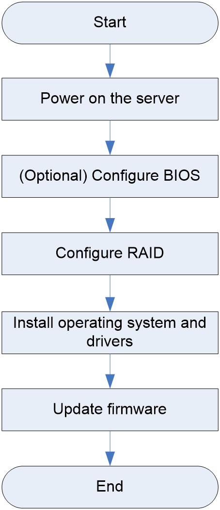
Powering on the server
1. Power on the server. For more information, see "Powering on the server."
2. Verify that the health LED on the front panel is steady green, which indicates that the system is operating correctly. For more information about the health LED status, see "LEDs and buttons."
Configuring BIOS settings
|
IMPORTANT: The BIOS setup utility screens are subject to change without notice. |
You can set the server boot order and the BIOS passwords from the BIOS setup utility of the server.
Setting the server boot order
The server has a default boot order. You can change the server boot order from the BIOS. For the default boot order and the procedure of changing the server boot order, see the BIOS user guide for the server.
Setting the BIOS passwords
BIOS passwords include a boot password as well as an administrator password and a user password for the BIOS setup utility. By default, no passwords are set.
To prevent unauthorized access and changes to the BIOS settings, set both the administrator and user passwords for accessing the BIOS setup utility. Make sure the two passwords are different.
After setting the administrator password and user password for the BIOS setup utility, you must enter the administrator password or user password each time you access the BIOS setup utility.
· To obtain administrator privileges, enter the administrator password.
· To obtain user privileges, enter the user password.
For the difference between the administrator and user privileges and guidelines for setting the BIOS passwords, see the BIOS user guide for the server.
Configuring RAID
The supported RAID levels and RAID configuration methods vary by storage controller model. For more information, see the storage controller user guide for the server.
Installing the operating system and drivers
Installing the operating system
The server supports multiple types of operating systems such as Windows and Linux. For the server compatibility with the operating systems, use the H3C Servers Compatibility Lookup Tools
Install a compatible operating system on the server by following the procedures described in the operating system installation guide for the server.
Installing drivers
|
|
IMPORTANT: To avoid hardware unavailability caused by an update failure, always back up the drivers before you update them. |
For newly installed hardware to operate correctly, the operating system must have the required hardware drivers.
Install compatible drivers in the operating system by following the procedures described in the operating system installation guide for the server.
Updating firmware
|
|
IMPORTANT: Verify the hardware and software compatibility before firmware upgrade. For information about the hardware and software compatibility, see the software release notes. |
You can update the following firmware from
UniSystem or HDM:
For the update procedures, see the firmware update guide for the server.
· HDM
· BIOS
· CPLD
· BPCPLD
· PSU
· LCD
· BMCCPLD
· SCPLD
Replacing hardware options
This section describes replaceable components of the server and the detailed procedures for component replacement.
|
|
NOTE: · If you are replacing multiple hardware options, read their replacement procedures and identify similar steps to streamline the entire replacement procedure. · This section includes operations for replacing components and expanding components. When there are significant differences, they will be introduced separately. When the procedures are similar, only the steps for replacing components will be detailed. If you are following the replacement steps for expansion, please remove the filler panel in advance. |
Replaceable components
The replaceable parts of the server include the following:
· Processor (Adding a processor and Replacing a processor)
· DIMM (Replacing a DIMM)
· System board (Replacing the system board)
· System management module (Replacing the server management module)
· SAS/SATA drive (Replacing an external SAS/SATA drive and Replacing an internal SAS/SATA drive)
· NVMe drive (Installing an NVMe drive and Replacing an NVMe drive)
· Drive backplane (Replacing a front drive backplane and Replacing a mid drive backplane)
· Riser card and PCIe card (Replacing a riser card and PCIe card, Installing a riser card and PCIe card to PCIe riser card slot 3 and Installing a riser card and PCIe card to PCIe riser card slot )
· Storage controller and its power fail safeguard module (Replacing a storage controller and its power fail safeguard module)
· Network adapter (Replacing a network adapter)
· Front M.2 SSD card and front M.2 SSD adapter (Replacing a front SATA/NVMe M.2 SSD and adapter)
· Rear M.2 SSD and rear M.2 SSD adapter (Replacing a rear SATA/NVMe M.2 SSD and adapter)
· Serial&DSD module (Replacing the serial&DSD module)
· SD card (Replacing an SD card)
· LCD smart management module (Installing an LCD smart management module and Replacing an LCD smart management module)
· Smart ear (Replacing a smart ear)
· Air baffle (Replacing an air baffle)
· Fan module (Replacing a module (embedded fan) and Replacing a fan module (front fan))
· Expander module (Replacing an expander module)
· Fan adapter module (Replacing a fan adapter module)
· Power distribution board (Replacing an upper power distribution board and Replacing a lower power distribution board)
· Encryption module (Installing an encryption module)
· Power module (Replacing a power module)
· NVMe VROC module (Replacing an NVMe VROC module)
· System battery (Replacing the system battery)
· Filler panel in each slot (Installing and removing filler panels in each slot)
Adding a processor
For information about how to add a processor, see the processor installation quick start.
Replacing a processor
Operation scenario
· The processor fails.
· Replace the processor with one of another model.
· The processor hinders maintenance of other components.
Prerequisites
· Wear antistatic clothing. Wear an ESD wrist strap and make sure it makes good skin contact and is reliably grounded. Wear ESD gloves. Do not wear any conductive objects, such as jewelry or watches.
· When you replace a component, examine the slot and connector for damages. Make sure the pins are not damaged (bent for example) and do not contain any foreign objects.
· For the specific installation guidelines of processors, see "Processors."
Procedure
|
|
IMPORTANT: · To avoid damage to a processor or the system board, only H3C authorized or professional server engineers can replace a processor. · Make sure the processors on the server are the same model. · The pins in the processor sockets are very fragile and prone to damage. Install a protective cover if a processor socket is empty. · For the server to operate correctly, make sure processor 1 is in position. For more information about processor locations, see "System board layout." · Different processors might have different heatsinks, but the processor replacement procedure is the same. · To prevent static electricity from damaging the electronic components, wear an ESD wrist strap before operation and ground the other end of the ESD wrist strap. |
Removing a processor
1. Power off the server. For more information, see "Powering off the server."
2. Remove the server from the rack. For more information, see "Removing the server."
3. Remove the access panel:
a. Press the button on the locking lever and then lift the locking lever. The access panel automatically slides to the server rear.
b. Lift the access panel to remove it from the server.
4. (Optional.) Remove the chassis air baffle.
5. Remove the processor heatsink:
a. Loosen the four captive screws.
b. Open heatsink clips at the four corners.
c. Lift the heatsink slowly to remove it.
|
|
IMPORTANT: The pins in the processor socket are extremely fragile and easily damaged. To avoid system board replacement caused by pin damage, do not touch the pins. |
6. Remove the processor:
a. Lift the locking lever to release the processor.
b. Hold the processor to pull it out from the retaining bracket.
7. Remove the processor retaining bracket from the heatsink:
a. Release the four corner clips of the retaining bracket from the heatsink. You must press one clip and its cater-cornered clip outward, and press the other two clips inward.
b. Lift the retaining bracket to remove it from the heatsink.
8. Use isopropanol wiping cloth to clear the residual thermal grease from the processor top and heatsink.
Installing a processor
1. Install the retaining bracket onto the heatsink:
a. Close the ejector lever on the retaining bracket for secure installation of the processor.
b. Align the triangle mark on the retaining bracket with the notched corner on the heatsink. Place the retaining bracket downward and press it until you hear a click, which indicates that the four corners of the retaining bracket are tightly locked with the four corners of the heatsink.
2. Smear thermal grease onto the processor: Use the thermal grease injector to inject 0.6 ml of thermal grease to the five dots on the processor.
|
|
IMPORTANT: Before this operation, clean the heatsink, and make sure no thermal grease remains on the heatsink top. |
3. Install the processor onto the retaining bracket:
|
|
IMPORTANT: To avoid damage to the processor, always hold the processor by its edges. Never touch the gold contacts on the processor bottom. |
a. Align the small triangle on the processor with the alignment triangle in the retaining bracket, and align the guide pin on the bracket with the notch on the triangle side of the processor.
b. Lower the processor gently and make sure the guide pins on the opposite side of the bracket fit snugly into notches on the processor.
4. Install the heatsink onto the server:
|
|
IMPORTANT: Paste bar code label supplied with the processor over the original label on the heatsink. This step is required for you to obtain H3C's processor servicing. |
a. Align the alignment triangle on the retaining bracket with the cut-off corner of the processor socket and the pin holes in the heatsink with the guide pins on the processor socket. Lower down the heatsink on the processor socket.
b. Press down the heatsink clips at the four corners to lock the heatsink in place.
c. Use a T30 Torx screwdriver to fasten the four captive screws on the heatsink.
|
|
IMPORTANT: To avoid poor contact between the processor and the system board or damage to the pins in the processor socket, tighten the screws to a torque value of 0.9 N·m (8 in-lbs). |
5. Install the chassis air baffle.
6. Place the access panel onto the server. Slide the access panel to the server front. Press down the wrench on the access panel until it snaps into place.
7. Install the server. For more information, see "Installing the server."
8. Connect the power cord.
9. Power on the server. For more information, see "Powering on the server."
Verifying the replacement
Log in to HDM and view the operating status of the processor to verify that the processor is operating correctly. For more information, see the HDM2 online help.
Replacing a DIMM
Operation scenario
· The DIMM fails.
· Replace the DIMM with one of another model.
· The DIMM hinders maintenance of other components.
Prerequisites
· Wear antistatic clothing. Wear an ESD wrist strap and make sure it makes good skin contact and is reliably grounded. Do not wear any conductive objects, such as jewelry or watches.
· When you replace a component, examine the slot and connector for damages. Make sure the pins are not damaged (bent for example) and do not contain any foreign objects.
· For the specific installation guidelines of DIMMs, see "Memory."
Replacement procedures
Removing the DIMM
1. Power off the server. For more information, see "Powering off the server."
2. Remove the server from the rack. For more information, see "Removing the server."
3. Remove the access panel.
a. Press the button on the locking lever and then lift the locking lever. The access panel automatically slides to the server rear.
b. Lift the access panel to remove it from the server.
4. Remove the DIMM: Open the DIMM slot latches and pull the DIMM out of the slot to remove the DIMM.
|
|
IMPORTANT: To avoid damage to DIMMs or the system board, make sure the server has been powered off correctly and the power cord has been disconnected for more than 20 seconds before removing DIMMs. |
Installing a DIMM
1. Align the notch at the bottom of the DIMM with that on the slot, and then insert the DIMM vertically along the slot by exerting uniform force. Now, the fixing clamp will be automatically locked. Make sure that the fixing clamp has locked the DIMM and is engaged tightly.
2. Install the access panel: Place the access panel onto the chassis, and slide the access panel to the server front until it is secured into place.
3. Install the server. For more information, see "Installing the server."
4. Connect the power cord.
5. Power on the server. For more information, see "Powering on the server."
Verifying the replacement
Use one of the following methods to verify that the DIMM is installed correctly:
· Using the operating system:
¡ In Windows, select Run in the Start menu, enter msinfo32, and verify the memory capacity of the DIMM.
¡ In Linux, execute the cat /proc/meminfo command to verify the memory capacity.
· Using HDM:
Log in to HDM and verify the memory capacity of the DIMM. For more information, see the HDM2 online help.
· Using BIOS:
Access the BIOS, select Socket Configuration > Memory Configuration > Memory Topology, and press Enter. Then, verify the memory capacity of the DIMM.
If the memory capacity displayed is inconsistent with the actual capacity, remove and then reinstall the DIMM, or replace the DIMM. If the DIMM is in Mirror mode, it is normal that the displayed capacity is smaller than the actual capacity.
Replacing the system board
Operation scenario
The system board fails.
Prerequisites
· Wear antistatic clothing. Wear an ESD wrist strap and make sure it makes good skin contact and is reliably grounded. Do not wear any conductive objects, such as jewelry or watches.
· When you replace a component, examine the slot and connector for damages. Make sure the pins are not damaged (bent for example) and do not contain any foreign objects.
Procedure
Remove the system board
|
|
IMPORTANT: To prevent electrostatic discharge, place the removed parts on an antistatic surface or in antistatic bags. |
1. Power off the server. For more information, see "Powering off the server."
2. Remove the server from the rack. For more information, see "Removing the server."
3. Remove the OCP network adapter.
4. Remove all power supplies.
5. Remove the access panel:
a. Press the button on the locking lever and then lift the locking lever. The access panel automatically slides to the server rear.
b. Lift the access panel to remove it from the server.
6. Lift the air baffle out of the chassis to remove the air baffle.
7. Remove the fans and fan cage.
8. Disconnect all cables from the system board.
9. Remove the cable cover from the side panel of the chassis.
10. Remove all components installed on the system board, for example, riser cards, DIMMs, and processors.
11. Install protective covers over the empty processor sockets.
12. Remove the system board:
a. Loosen the captive screws on the system board.
b. Hold the system board handle and slide the system board toward the server front to disengage the system board and the server management module. Then, lift the system board to remove it from the chassis.
Installing the system board
1. Install the system board:
a. Slowly place the system board in the chassis. Then, hold the system board handle and slide the system board toward the server rear until the system board connector is successfully inserted into the server management module.
|
|
NOTE: The system board is securely seated if you cannot use the system board handle to lift the system board. |
b. Fasten the captive screws on the system board.
2. Install the removed cable cover.
3. Reconnect cables to the system board.
4. Remove the installed protective covers over the processor sockets. Hold a cover and lift it straight up and away from a socket.
5. Install the removed components (for example, riser cards, DIMMs, and processors) to the system board.
6. Install the chassis air baffle.
7. Install the fans and fan cage.
8. Install the access panel.
9. Install the OCP network adapter.
10. Install power supplies.
11. Install the server. For more information, see "Installing the server."
12. Connect the power cord.
13. Power on the server. For more information, see "Powering on the server."
Replacing the server management module
Operation scenario
The server management module fails.
Prerequisites
· Wear antistatic clothing. Wear an ESD wrist strap and make sure it makes good skin contact and is reliably grounded. Do not wear any conductive objects, such as jewelry or watches.
· When you replace a component, examine the slot and connector for damages. Make sure the pins are not damaged (bent for example) and do not contain any foreign objects.
Procedure
Removing the server management module
1. Power off the server. For more information, see "Powering off the server."
2. Remove the server from the rack. For more information, see "Removing the server."
3. Remove the OCP network adapter.
4. Remove all power supplies.
5. Remove the access panel:
a. Press the button on the locking lever and then lift the locking lever. The access panel automatically slides to the server rear.
b. Lift the access panel to remove it from the server.
6. Remove the air baffle. Open the blue clip on the air baffle, and lift the air baffle out of the chassis.
7. Remove the fans and fan cage.
8. Disconnect all cables from the system board.
9. Remove the cable cover.
10. Remove all components installed on the system board, for example, riser cards, DIMMs, and processors.
11. Install protective covers over the empty processor sockets.
12. Remove the system board:
a. Loosen the captive screws on the system board.
b. Hold the system board handle and slide the system board toward the server front to disengage the system board and the server management module. Then, lift the system board to remove it from the chassis.
13. Remove the server management module. Slide the management module toward the server front to disengage the connectors on the module and the rear panel. Lift the management module out of the chassis.
Installing a server management module
1. Slowly place the management module into the chassis. Then, slide the management module toward the server rear until the connectors on the module are securely seated.
2. Install the system board:
a. Slowly place the system board into the chassis. Then, hold the system board handle and slide the system board toward the server rear until the system board connector is successfully inserted into the server management module.
|
|
NOTE: The system board is securely seated if you cannot use the system board handle to lift the system board. |
b. Fasten the captive screws on the system board.
3. Install the removed cable cover.
4. Reconnect cables to the system board.
5. Remove the installed protective covers over the processor sockets. Hold a cover and lift it straight up and away from a socket.
6. Install the removed components (for example, riser cards, DIMMs, and processors) to the system board.
7. Install the fans and fan cage.
8. Install the chassis air baffle.
9. Install the access panel.
10. Install the OCP network adapter.
11. Install power supplies.
12. Install the server. For more information, see "Installing the server."
13. Connect the power cord.
14. Power on the server. For more information, see "Powering on the server."
Replacing an external SAS/SATA drive
Operation scenario
· The drive space is used up.
· Replace the drive with one of another model.
Prerequisites
· Wear antistatic clothing. Wear an ESD wrist strap and make sure it makes good skin contact and is reliably grounded. Do not wear any conductive objects, such as jewelry or watches.
· When you replace a component, examine the slot and connector for damages. Make sure the pins are not damaged (bent for example) and do not contain any foreign objects.
· Identify the position of the drive to be replaced.
· Identify the RAID information of the drive to be replaced. To replace it with a different model of drive or the drive is full, and the RAID to which the drive belongs has no redundancy, back up the data in the RAID in advance.
· For the specific installation guidelines of SAS/SATA drives, see "SAS/SATA drives."
Replacement procedures
SAS/SATA drives managed by a storage controller support hot swapping only after the device enters the BIOS or operating system.
SATA drives managed by the embedded VROC controller support hot swapping only after the device enters the operating system.
Removing the SAS/SATA drive
1. Observe the drive LEDs to verify that the drive can be removed. For more information about drive LEDs, see "Drive LEDs."
2. Remove the drive. Press the button on the drive panel, and the drive handle will automatically open. Then pull the hard drive out of the drive bay. To remove an HDD, press the button on the drive panel to release the locking lever. Pull the drive 3 cm (1.18 in) out of the slot. Wait for a minimum of 30 seconds for the drive to stop rotating, and then pull the drive out of the slot.
3. Remove the drive carrier. Remove the screws that secure the drive and then remove the drive from the carrier.
Installing a SAS/SATA drive
|
IMPORTANT: As a best practice, install drives that do not contain RAID information. |
1. Attach the drive to the drive carrier. Place the drive in the carrier and then use four screws to secure the drive into place.
2. Insert the drive into the slot and push it gently until you cannot push it further, and then close the locking lever.
3. (Optional.) Clear the RAID information (if any) on the new drive.
4. After the storage controller detects the new SAS/SATA drive, confirm whether to configure RAID. For the method of configuring RAID, see the storage controller user guide.
Verifying the replacement
Use one of the following methods to verify that the drive has been replaced correctly:
· Log in to HDM, verify that the drive capacity after RAID setup is correct. For more information, see the HDM2 online help.
· Observe the drive LEDs to verify that the drive is operating correctly. For more information about drive LEDs, see "Drive LEDs."
· Verify that the drive capacity is correct through the BIOS. The method for viewing drive information in the BIOS might vary by RAID configuration. For more information, see the storage controller user guide.
· Access the operating system to verify that the drive capacity is correct.
Replacing an internal SAS/SATA drive
Operation scenario
· The drive fails.
· The drive space is used up.
· Replace the drive with one of another model.
Prerequisites
· Wear antistatic clothing. Wear an ESD wrist strap and make sure it makes good skin contact and is reliably grounded. Do not wear any conductive objects, such as jewelry or watches.
· When you replace a component, examine the slot and connector for damages. Make sure the pins are not damaged (bent for example) and do not contain any foreign objects.
· Identify the position of the drive to be replaced.
· Identify the RAID information of the drive to be replaced. To replace it with a different model of drive or the drive is full, and the RAID to which the drive belongs has no redundancy, back up the data in the RAID in advance.
· For the specific installation guidelines of SAS/SATA drives, see "SAS/SATA drives."
Procedure
SAS/SATA drives managed by a storage controller support hot swapping only after the device enters the BIOS or operating system.
SATA drives managed by the embedded VROC controller support hot swapping only after the device enters the operating system.
Removing the SAS/SATA drive
|
|
IMPORTANT: Make sure the side mounting ears on the server are locked with the square holes before pulling out the 3U hard drive drawer or performing similar operations. Do not pull out the 3U hard drive drawer on a flat surface to avoid downward sagging and scraping against the table. Control the time spent on maintaining the 3U hard drive drawer. Avoid prolonged hot-swapping of the 60LFF drives in the drawer to prevent overheating and triggering hard drive alarms. |
1. After pulling out the 3U drive drawer, check the status of the drive through the LED to determine if it can be removed. For more information about drive LEDs, see "Drive LEDs."
2. Remove the drive: Unlock the latch on the drive handle, move the handle to the maximum position, and then pull the drive out of the drive bay. For HDDs, after opening the drive handle, move the handle to the maximum position to offline the drive; then wait at least 30 seconds until the drive completely stops spinning before pulling the drive out of the bay.
3. Remove the drive carrier: Remove the securing screws on the drive carrier and open the latch on the drive carrier, and then remove the drive from the drive carrier.
Installing a SAS/SATA drive
|
|
IMPORTANT: As a best practice, install drives that do not contain RAID information. |
1. Attach the drive to the drive carrier. Insert one securing screw into the screw hole, and then tighten the screw.
2. Install the drive. Insert the drive into the slot and push it gently until you cannot push it further, and then close the locking lever.
3. (Optional.) Clear the RAID information (if any) on the new drive.
4. After the storage controller detects the new SAS/SATA drive, confirm whether to configure RAID. For the method of configuring RAID, see the storage controller user guide.
Verifying the replacement
Use one of the following methods to verify that the drive has been replaced correctly:
· Log in to HDM, verify that the drive capacity after RAID setup is correct. For more information, see the HDM2 online help.
· Observe the drive LEDs to verify that the drive is operating correctly. For more information about drive LEDs, see "Drive LEDs."
· Verify that the drive capacity is correct through the BIOS. The method for viewing drive information in the BIOS might vary by RAID configuration. For more information, see the storage controller user guide.
· Access the operating system to verify that the drive capacity is correct.
Installing an NVMe drive
Prerequisites
· Wear antistatic clothing. Wear an ESD wrist strap and make sure it makes good skin contact and is reliably grounded. Do not wear any conductive objects, such as jewelry or watches.
· When you replace a component, examine the slot and connector for damages. Make sure the pins are not damaged (bent for example) and do not contain any foreign objects.
· Identify the position of the drive to be replaced.
· Identify the RAID information of the drive to be replaced. To replace it with a different model of drive or the drive is full, and the RAID to which the drive belongs has no redundancy, back up the data in the RAID in advance.
· For the specific installation guidelines of SAS/SATA drives, see "NVMe drives."
Procedure
|
|
NOTE: NVMe drives are hot swappable in some operating systems. For more information, use the OS compatibility lookup tool. |
1. Attach the drive to the drive carrier. Place the drive in the carrier and then use four screws to secure the drive into place.
2. Install the NVMe drive.
¡ If the NVMe drive supports hot swapping, see the NVMe drive online replacement guide.
¡ If the NVMe drive does not support hot swapping, go to the following steps.
3. Power off the server. For more information, see "Powering off the server."
4. Insert the drive into the drive bay, then close the drive handle.
Verifying the replacement
Use one of the following methods to verify that the NVMe drive has been installed correctly:
· Log in to HDM, and verify that the NVMe drive capacity is correct. For more information, see the HDM2 online help.
· Observe the NVMe drive LEDs to verify that the drive is operating correctly. For more information about drive LEDs, see "Drive LEDs."
· Verify that the NVMe drive capacity is correct through the BIOS. For more information, see the BIOS user guide.
· Access the operating system to verify that the NVMe drive capacity is correct.
Replacing an NVMe drive
Operation scenario
· The drive fails.
· The drive space is used up.
· Replace the drive with one of another model.
Prerequisites
· Wear antistatic clothing. Wear an ESD wrist strap and make sure it makes good skin contact and is reliably grounded. Do not wear any conductive objects, such as jewelry or watches.
· When you replace a component, examine the slot and connector for damages. Make sure the pins are not damaged (bent for example) and do not contain any foreign objects.
· Identify the position of the drive to be replaced.
· Identify the RAID information of the drive to be replaced. To replace it with a different model of drive or the drive is full, and the RAID to which the drive belongs has no redundancy, back up the data in the RAID in advance.
· For the specific installation guidelines of SAS/SATA drives, see "NVMe drives."
Replacement procedures
|
|
NOTE: Some operating systems support NVMe drive hot swapping. To replace an NVMe drive in an operating system that does not support NVMe drive hot swapping, power off the server first. For more information, see "Powering off the server." |
Removing the NVMe drive
1. Use the OS compatibility query tool to check if the NVMe drive supports hot swapping or managed hot swapping under the operating system.
¡ If neither is supported, power off the server. For more information, see "Powering off the server." Then, go to steps 2 and 3.
¡ If either is supported, see the NVMe drive online replacement guide.
2. Remove the NVMe drive. Press the button on the drive panel, and the drive handle will automatically open. Then pull the drive out of the drive bay.
Installing the NVMe drive
1. Identify whether the NVMe drive was hot removed.
¡ If it was, see the NVMe drive online replacement guide.
¡ If it was not, go to steps 2 and 3.
3. Install the NVMe drive. Insert the drive into the drive bay, then close the drive handle
Verifying the replacement
Use one of the following methods to verify that the NVMe drive has been replaced correctly:
· Log in to HDM, and verify that the NVMe drive capacity is correct. For more information, see the HDM2 online help.
· Observe the NVMe drive LEDs to verify that the drive is operating correctly. For more information about drive LEDs, see "Drive LEDs."
· Verify that the NVMe drive capacity is correct through the BIOS. For more information, see the BIOS user guide.
· Access the operating system to verify that the NVMe drive capacity is correct.
Replacing a front drive backplane
Operation scenario
The drive backplane fails.
Prerequisites
· Wear antistatic clothing. Wear an ESD wrist strap and make sure it makes good skin contact and is reliably grounded. Do not wear any conductive objects, such as jewelry or watches.
· When you replace a component, examine the slot and connector for damages. Make sure the pins are not damaged (bent for example) and do not contain any foreign objects.
Replacement procedures
Removing the drive backplane
1. Power off the server. For more information, see "Powering off the server."
2. Remove the server from the rack. For more information, see "Removing the server."
3. Remove all drives on the drive backplane.
4. Remove the access panel:
a. Press the button on the locking lever and then lift the locking lever. The access panel automatically slides to the server rear.
b. Lift the access panel to remove it from the server.
5. Disconnect all cables from the drive backplane.
6. Remove the drive backplane. Loosen the captive screws on the drive backplane, and then lift the drive backplane upward to detach it from the server.
Installing the drive backplane
1. Install the drive backplane. Lower the backplane into the slot, and then tighten the captive screws on the backplane.
2. Connect all drive backplane cables.
3. Install the access panel. Place the access panel onto the chassis, and slide the access panel to the server front until it is secured into place.
4. Installed the removed drives.
5. Install the server. For more information, see "Installing the server."
6. Connect the power cord.
7. Power on the server. For more information, see "Powering on the server."
Replacing a mid drive backplane
Operation scenario
The drive backplane fails.
Prerequisites
· Wear antistatic clothing. Wear an ESD wrist strap and make sure it makes good skin contact and is reliably grounded. Do not wear any conductive objects, such as jewelry or watches.
· When you replace a component, examine the slot and connector for damages. Make sure the pins are not damaged (bent for example) and do not contain any foreign objects.
Procedure
Removing the drive backplane
1. Power off the server. For more information, see "Powering off the server. "
2. Remove the server from the rack. For more information, see "Removing the server."
3. Pull out the lower 3U drive drawer. Press the inner structures of the two handles at the front of the drawer to unlock the slides, and then pull the drive drawer outward.
4. Remove all drives on the drive backplane. For more information, see "Removing the SAS/SATA drive."
5. Remove the drive backplane. Use a screwdriver to assist in lifting the drive backplane upward, detaching it from the drive drawer.
Installing the drive backplane
1. Install the drive backplane. Place the backplane into the slot.
2. Install the removed drives.
3. Push in the lower 3U drive drawer. Press the inner structures of the two handles at the front of the drawer to unlock the slides, and then slide the drive drawer inward until it is properly installed.
4. Install the server. For more information, see "Installing the server."
5. Connect the power cord.
6. Power on the server. For more information, see "Powering on the server."
Replacing a riser card and PCIe card
Operation scenario
· The riser card fails.
· The PCIe card fails.
· Replace the PCIe card with one of another model.
Prerequisites
· Wear antistatic clothing. Wear an ESD wrist strap and make sure it makes good skin contact and is reliably grounded. Do not wear any conductive objects, such as jewelry or watches.
· When you replace a component, examine the slot and connector for damages. Make sure the pins are not damaged (bent for example) and do not contain any foreign objects.
· Learn the riser card and PCIe card installation guidelines. For more information, see "Riser cards and PCIe modules."
Replacement procedures
Removing the riser card and PCIe card
1. Power off the server. For more information, see "Powering off the server."
2. Remove the server from the rack. For more information, see "Removing the server."
3. Remove the access panel:
a. Press the button on the locking lever and then lift the locking lever. The access panel automatically slides to the server rear.
b. Lift the access panel to remove it from the server.
4. (Optional.) Disconnect all cables obstructing the riser card operation.
5. Remove the Riser card with the PCIe card. Lift the Riser card upward to detach it from the chassis.
6. Remove the PCIe card from the Riser card. Open the Riser card retaining cover, and then pull the PCIe card out of the slot.
Installing the riser card and PCIe card
1. Install the riser card and PCIe card.
a. Remove the PCIe card filler panel from the riser card. Open the riser card retaining cover, and then pull out the filler panel.
b. Install the PCIe card into the riser card. Insert the PCIe card into the PCIe slot, and then close the Riser card retaining cover.
2. Install the riser card with the PCIe card into the server.
a. Remove the filler panel of the PCIe Riser card slot. Lift the filler panel upward to detach it from the server chassis.
b. Install the Riser card with the PCIe card. Align the two protrusions on the Riser card with the two notches on the chassis, and insert the Riser card into the PCIe slot.
3. (Optional) If the installed Riser card or PCIe card requires cabling, connect the necessary cables.
4. Install the access panel. Place the access panel onto the chassis, and slide the access panel to the server front until it is secured into place.
5. Install the server. For more information, see "Installing the server."
6. Connect the power cord.
7. Power on the server. For more information, see "Powering on the server."
Installing a riser card and PCIe card to PCIe riser card slot 3
Prerequisites
· Wear antistatic clothing. Wear an ESD wrist strap and make sure it makes good skin contact and is reliably grounded. Do not wear any conductive objects, such as jewelry or watches.
· When you replace a component, examine the slot and connector for damages. Make sure the pins are not damaged (bent for example) and do not contain any foreign objects.
· Learn the PCIe riser card installation guidelines. For more information, see "Riser cards and PCIe modules."
Procedure
1. Identify the PCIe riser card slot position. For more information, see "System board layout."
2. Power off the server. For more information, see "Powering off the server."
3. Remove the server from the rack. For more information, see "Removing the server."
a. Press the button on the locking lever and then lift the locking lever. The access panel automatically slides to the server rear.
b. Lift the access panel to remove it from the server.
5. Remove the PCIe Riser card filler panel. Take out the PCIe Riser card filler panel.
6. Install the Riser card and PCIe card. Insert the PCIe card into the PCIe slot on the Riser card.
7. Install the Riser card with the PCIe card into the server. Install the riser card onto the PCIe riser connector.
8. (Optional.) If the installed Riser card or PCIe card requires cabling, connect the necessary cables.
10. Install the server. For more information, see "Installing the server."
11. Connect the power cord.
12. Power on the server. For more information, see "Powering on the server."
Installing a riser card and PCIe card to PCIe riser card slot 4
Prerequisites
· Wear antistatic clothing. Wear an ESD wrist strap and make sure it makes good skin contact and is reliably grounded. Do not wear any conductive objects, such as jewelry or watches.
· When you replace a component, examine the slot and connector for damages. Make sure the pins are not damaged (bent for example) and do not contain any foreign objects.
· Learn the PCIe riser card installation guidelines. For more information, see "Riser cards and PCIe modules."
Procedure
1. Identify the PCIe riser card slot position. For more information, see "Front panel."
2. Power off the server. For more information, see "Powering off the server."
3. Remove the server from the rack. For more information, see "Removing the server."
4. Remove the access panel. Press the button on the locking lever and then lift the locking lever. The access panel automatically slides to the server rear. Lift the access panel to remove it from the server.
5. Remove the PCIe Riser card filler panel. From inside the chassis, use a screwdriver to push both sides of the filler panel with force. Once the filler panel has moved out a certain distance, pull it out completely.
6. Connect the cables to the Riser card.
7. Install the Riser card. Insert the Riser card and secure it with screws.
8. Connect the cables to the system board. Connect the power cable to the power interface 3, the signal cable to the AUX interface 8, and for data cable connections, see Table 35.
9. Install the access panel. Place the access panel onto the chassis, and slide the access panel to the server front until it is secured into place.
10. Install the server. For more information, see "Installing the server."
11. Connect the power cord.
12. Power on the server. For more information, see "Powering on the server."
Replacing a storage controller and its power fail safeguard module
Operation scenario
· The storage controller fails.
· Replace the storage controller with one of another model.
· The storage controller is obstructing the maintenance operations of other components.
· The power fail safeguard module fails.
· The power fail safeguard module is obstructing the maintenance operations of other components.
Prerequisites
· Wear antistatic clothing. Wear an ESD wrist strap and make sure it makes good skin contact and is reliably grounded. Do not wear any conductive objects, such as jewelry or watches.
· When you replace a component, examine the slot and connector for damages. Make sure the pins are not damaged (bent for example) and do not contain any foreign objects.
· To replace it with a storage controller of the same model, clearly identify the storage controller and its BIOS information.
¡ The storage controller's position in the server and cable connection method.
¡ Model, operation mode, and firmware version of the storage controller.
¡ Identify the BIOS boot mode.
¡ Identify the first boot option setting for the storage controller in Legacy boot mode.
· To replace it with a storage controller of a different model, back up the data on the disks controlled by the storage controller and clear RAID configuration information in advance.
· Learn the storage controller and power fail safeguard module installation guidelines. For more information, see Storage controller and power fail safeguard module.
Procedure
Removing the standard storage controller and power fail safeguard module
1. Power off the server. For more information, see Powering off the server.
2. Remove the server from the rack. For more information, see Removing the server.
3. Remove the access panel. Press the button on the locking lever and then lift the locking lever. The access panel automatically slides to the server rear. Lift the access panel to remove it from the server.
4. Disconnect all standard storage controller cables.
5. Remove the standard storage controller.
a. Remove the Riser card with the storage controller. Lift the Riser card upward to detach it from the chassis.
b. Remove the storage controller from the Riser card. Unscrew the retaining screws on the Riser card, and then pull the PCIe card out of the slot.
6. (Optional.) If the standard storage controller is configured with a power fail safeguard module or supercapacitor, remove it.
a. Remove the Flash card. Unscrew the retaining screws on the Flash card, and then pull out the Flash card.
b. Remove the supercapacitor. Pry open the retaining clips of the capacitor and simultaneously pull the capacitor out of the slot.
c. Remove the supercapacitor holder. Pry open the clips at the bottom of the holder and simultaneously pull the holder out of the slot.
Installing the standard storage controller and power fail safeguard module
1. (Optional.) Install the supercapacitor and holder.
a. Install the supercapacitor holder to the server's air baffle. Place the holder horizontally into the chassis, and then slide it in the direction of the arrow until you hear a click.
b. Connect the supercapacitor adapter cable to one end of the supercapacitor.
c. Install the supercapacitor into the holder. Tilt the capacitor, align one end of the capacitor with one end of the holder, then pry open the clips on the holder and place the other end of the capacitor into the holder, securing it with the clips.
2. (Optional.) If a flash card is configured in the power fail safeguard module, install it.
a. Install the standoffs included with the power fail safeguard module onto the control card.
b. Install the Flash card onto the standard storage controller. Align the two mounting holes on the Flash card with the two standoffs on the control card, insert the Flash card downward, and secure it with screws.
3. Install the standard storage controller onto the Riser card. Insert the standard storage controller along the PCIe slot, and then secure the storage controller with screws.
4. Install the Riser card with the standard storage controller into the server.
5. Connect the data cable between the standard storage controller and the drive backplane.
6. (Optional.) If you have installed a power fail safeguard module, connect the adapter cable with the supercapacitor to the flash connector.
7. Install the access panel. Place the access panel onto the chassis, and slide the access panel to the server front until it is secured into place.
8. Install the server. For more information, see "Installing the server."
9. Connect the power cord.
10. Power on the server. For more information, see Powering on the server.
11. Perform the following tasks:
¡ If a different model of standard storage controller is installed, configure RAID for the disks controlled by the standard storage controller. For specific instructions, refer to the product’s storage controller user guide.
¡ If a storage controller of the same model is installed, to reduce the risk of data loss and corruption, make sure the following information is consistent before and after the replacement: the operation mode of the standard storage controller, firmware version, BIOS boot mode, and the first boot option setting for the standard storage controller in Legacy boot mode. For detailed instructions, refer to the product’s storage controller user guide and BIOS user guide.
Replacing a network adapter
Operation scenario
· The OCP network adapter fails.
· The standard PCIe network adapter fails.
· Replace the OCP network adapter with one of another model.
· Replace the standard PCIe network adapter with one of another model.
Prerequisites
· Wear antistatic clothing. Wear an ESD wrist strap and make sure it makes good skin contact and is reliably grounded. Do not wear any conductive objects, such as jewelry or watches.
· When you replace a component, examine the slot and connector for damages. Make sure the pins are not damaged (bent for example) and do not contain any foreign objects.
· Learn the network adapter installation guidelines. For more information, see Network adapters.
Installing an OCP network adapter
1. Power off the server. For more information, see Powering off the server.
2. Remove the OCP network adapter filler panel.
3. Install the OCP network adapter. Insert the OCP network adapter into the slot, and tighten the captive screws on the network adapter.
4. Connect the OCP network adapter cables.
5. Power on the server. For more information, see Powering on the server.
6. (Optional.) The OCP network adapter supports the NCSI feature and allows for the configuration of the HDM shared network interface. By default, the Port1 interface on the OCP network adapter is set as the HDM shared network interface. Users can configure other interfaces on the OCP network adapter as the HDM shared network interface via the HDM Web interface. It is important to note that at any given time, only one network interface on the server can be configured as the HDM shared network interface.
Replacing an OCP network adapter
The server supports predictive hot swapping of the OCP network adapter. For detailed instructions, see appendix B.
This section only provides the steps for replacing the OCP network adapter when the server is powered off.
Removing the OCP network adapter
1. Power off the server. For more information, see Powering off the server.
2. Disconnect all OCP network adapter cables.
3. Remove the OCP network adapter. Loosen the captive screws of the OCP network adapter, and then remove the OCP network adapter from the slot.
Installing the OCP network adapter
1. Install the OCP network adapter. Insert the OCP network adapter into the slot, and then tighten the captive screws on the network adapter.
2. Connect all OCP network adapter cables.
3. Power on the server. For more information, see Powering on the server.
4. (Optional.) The OCP network adapter supports the NCSI feature and allows for the configuration of the HDM shared network interface. By default, the Port1 interface on the OCP network adapter is set as the HDM shared network interface. Users can configure other interfaces on the OCP network adapter as the HDM shared network interface via the HDM Web interface. It is important to note that at any given time, only one network interface on the server can be configured as the HDM shared network interface.
Replacing a standard PCIe network adapter
Removing the standard PCIe network adapter
1. Power off the server. For more information, see Powering off the server.
2. Disconnect all PCIe network adapter cables.
3. Remove the server from the rack. For more information, see Removing the server.
4. Remove the access panel. Press the button on the locking lever and then lift the locking lever. The access panel automatically slides to the server rear. Lift the access panel to remove it from the server.
5. (Optional.) Disconnect all cables obstructing the operation of the Riser card.
6. Remove the Riser card with the standard PCIe network adapter. Lift the Riser card upward to disengage it from the chassis.
7. Remove the standard PCIe network adapter from the Riser card. Loosen the screws securing the adapter to the Riser card, and then pull the standard PCIe network adapter out of the slot.
Installing the standard PCIe network adapter
For more information, see "Installing the riser card and PCIe."
Replacing a front SATA/NVMe M.2 SSD and adapter
Operation scenario
· The front SATA/NVMe M.2 SSD fails.
· The front SATA/NVMe M.2 SSD adapter fails.
· Replace the front SATA/NVMe M.2 SSD or adapter with one of another model.
Prerequisites
· Wear antistatic clothing. Wear an ESD wrist strap and make sure it makes good skin contact and is reliably grounded. Do not wear any conductive objects, such as jewelry or watches.
· When you replace a component, examine the slot and connector for damages. Make sure the pins are not damaged (bent for example) and do not contain any foreign objects.
· Learn the front SATA/NVMe M.2 SSD installation guidelines. For more information, see M.2 SSDs.
Procedure
Removing the front SATA/NVMe M.2 SSD
1. Power off the server. For more information, see Powering off the server.
2. Remove the server from the rack. For more information, see Removing the server.
3. Remove the access panel. Press the button on the locking lever and then lift the locking lever. The access panel automatically slides to the server rear. Lift the access panel to remove it from the server.
4. Remove the adapter card with the front SATA/NVMe M.2 SSD.
a. Disconnect the cables on the front SATA/NVMe M.2 SSD adapter.
b. Remove the front SATA/NVMe M.2 SSD adapter card. Remove all screws on the adapter card, and then lift the adapter card out of the server chassis.
5. Remove the front SATA/NVMe M.2 SSD. Press the retention clip on the adapter card, the front SATA/NVMe M.2 SSD will automatically pop up, then pull out the SATA/NVMe M.2 SSD.
Installing the front SATA/NVMe M.2 SSD adapter and SSD
1. Install the front SATA/NVMe M.2 SSD onto the front SATA/NVMe M.2 SSD adapter. Insert the front SATA/NVMe M.2 SSD into the slot on the adapter, then press down the other side to secure it with the retention clip.
2. Install the adapter card with the front SATA/NVMe M.2 SSD into the server.
a. Align the two screw holes on the adapter card with the two standoffs on the chassis, place the adapter down, and secure it with screws.
b. Connect the SATA/NVMe M.2 SSD data cables. For more information, see "Connecting front SATA/NVMe M.2 SSD data cable."
3. Install the access panel. Place the access panel onto the chassis, and slide the access panel to the server front until it is secured into place.
4. Install the server. For more information, see "Installing the server."
5. Connect the power cord.
6. Power on the server. For more information, see "Powering on the server."
Replacing a rear SATA/NVMe M.2 SSD and adapter
Operation scenario
· The rear SATA/NVMe M.2 SSD fails.
· The rear SATA/NVMe M.2 SSD adapter fails.
· Replace the rear SATA/NVMe M.2 SSD or adapter with one of another model.
Prerequisites
· Wear antistatic clothing. Wear an ESD wrist strap and make sure it makes good skin contact and is reliably grounded. Do not wear any conductive objects, such as jewelry or watches.
· When you replace a component, examine the slot and connector for damages. Make sure the pins are not damaged (bent for example) and do not contain any foreign objects.
· Learn front SATA/NVMe M.2 SSD installation guidelines. For more information, see M.2 SSDs.
Procedure
Removing the rear SATA/NVMe M.2 SSD
1. Power off the server. For more information, see Powering off the server.
2. Remove the server from the rack. For more information, see Removing the server.
3. Remove the access panel.
4. Remove the Riser card with the rear SATA/NVMe M.2 SSD adapter card.
a. Disconnect all SATA/NVMe M.2 SSD adapter cables.
b. Remove the riser card. For more information, see "Replacing a riser card and PCIe card."
5. Remove the rear SATA/NVMe M.2 SSD adapter. For more information, see "Replacing a riser card and PCIe card."
6. Remove the rear SATA/NVMe M.2 SSD. Loosen the securing screws, and then pull out the rear SATA/NVMe M.2 SSD card.
Installing the rear SATA/NVMe M.2 SSD adapter and SSD
1. Install the rear SATA/NVMe M.2 SSD card onto the rear SATA/NVMe M.2 SSD adapter card. Insert the rear SATA/NVMe M.2 SSD card into the slot on the adapter card, and then secure it with the screws.
2. Install the adapter card with the rear SATA/NVMe M.2 SSD card onto the Riser card. For more information, see "Installing the riser card and PCIe."
3. Install the Riser card with the rear SATA/NVMe M.2 SSD adapter card into the server. For more information, see "Installing the riser card and PCIe."
4. Install the access panel.
5. Install the server. For more information, see "Installing the server."
6. Connect the power cord.
7. Power on the server. For more information, see Powering on the server.
Replacing the serial&DSD module
Prerequisites
· Wear antistatic clothing. Wear an ESD wrist strap and make sure it makes good skin contact and is reliably grounded. Do not wear any conductive objects, such as jewelry or watches.
· When you replace a component, examine the slot and connector for damages. Make sure the pins are not damaged (bent for example) and do not contain any foreign objects.
Procedure
Removing the serial&DSD module
1. Power off the server. For more information, see Powering off the server.
2. Remove the serial&DSD module. Loosen the captive screws on the serial & DSD module, and then pull the serial & DSD module out of the slot.
Installing the serial&DSD module
1. Install the serial & DSD module. Push the serial & DSD module into the slot, and then tighten the captive screws on the serial & DSD module.
2. Power on the server. For more information, see Powering on the server.
Replacing an SD card
Operation scenario
· The SD card fails.
· The dual-SD card expander module fails.
· Replace the SD card with one of another model.
Prerequisites
· Wear antistatic clothing. Wear an ESD wrist strap and make sure it makes good skin contact and is reliably grounded. Do not wear any conductive objects, such as jewelry or watches.
· When you replace a component, examine the slot and connector for damages. Make sure the pins are not damaged (bent for example) and do not contain any foreign objects.
Procedure
Removing the SD card
1. Power off the server. For more information, see Powering off the server.
2. Remove the serial&DSD module. Loosen the captive screws on the serial & DSD module, and then pull the serial & DSD module out of the slot.
3. Remove the SD card to be replaced from the serial & DSD module. Gently push the SD card until it pops out, and then pull the SD card out.
Install a SD
1. Insert the SD card into the SD card slot, and then gently push the SD card until it locks into place in the slot.
2. Install the serial & DSD module. Push the serial & DSD module into the slot, and then tighten the captive screws on the serial & DSD module.
3. Power on the server. For more information, see Powering on the server.
Installing an LCD smart management module
Prerequisites
· Wear antistatic clothing. Wear an ESD wrist strap and make sure it makes good skin contact and is reliably grounded. Do not wear any conductive objects, such as jewelry or watches.
· Before installing the components, please inspect the slot or connector to ensure that the pins are not damaged (e.g., bent pins or foreign objects on the connector).
· Learn the LCD smart management module installation guidelines. For more information, see LCD smart management module.
Procedure
1. Power off the server. For more information, see Powering off the server.
2. Remove the server. For more information, see Removing the server.
3. Remove the access panel. Press the button on the locking lever and then lift the locking lever. The access panel automatically slides to the server rear. Lift the access panel to remove it from the server.
4. Remove the hard drive or hard drive filler panel from the slot where the new component will be installed.
5. Install the LCD smart management module.
a. Connect the LCD smart management module adapter cable.
b. Push the LCD smart management module into the slot until it cannot go any further.
c. Connect the LCD smart management module cable to the LCD smart management module interface on the system board.
6. Install the access panel. Place the access panel onto the chassis, and slide the access panel to the server front until it is secured into place.
7. Install the server. For more information, see "Installing the server."
8. Connect the power cable. For more information, see Connecting a power cord.
9. Power on the server. For more information, see Powering on the server.
Replacing an LCD smart management module
Operation scenario
· The LCD smart management module fails.
· The LCD smart management module obstructs the maintenance of other components.
Prerequisites
· Wear antistatic clothing. Wear an ESD wrist strap and make sure it makes good skin contact and is reliably grounded. Do not wear any conductive objects, such as jewelry or watches.
· When you replace a component, examine the slot and connector for damages. Make sure the pins are not damaged (bent for example) and do not contain any foreign objects.
Procedure
Removing the LCD smart management module
1. Power off the server. For more information, see Powering off the server.
2. Remove the server from the rack. For more information, see Removing the server.
3. Remove the access panel. Press the button on the locking lever and then lift the locking lever. The access panel automatically slides to the server rear. Lift the access panel to remove it from the server.
4. Remove the LCD smart management module.
a. Disconnect the LCD smart management module adapter cable from the system board.
b. Use a T10 Torx screwdriver or tweezers to hold down the release clips of the LCD smart management module, and then pull the LCD smart management module out of the slot.
Installing the LCD smart management module
1. Install the LCD smart management module.
a. Connect the LCD smart management module adapter cable.
b. Push the LCD smart management module into the slot until it cannot go any further.
c. Connect the LCD smart management module cable to the LCD smart management module interface on the system board.
2. Install the access panel. Place the access panel onto the chassis, and slide the access panel to the server front until it is secured into place.
3. Install the server. For more information, see "Installing the server."
4. Connect the power cord.
5. Power on the server. For more information, see Powering on the server.
Replacing a smart ear
Operation scenario
· The smart ear fails.
· Failure of components integrated into the smart ear, such as I/O components, VGA/USB ports, etc.
Procedure
The replacement methods for the smart ears on both sides are similar. This document will use the replacement of the left smart ear as an example.
Removing the smart ear
1. Power off the server. For more information, see Powering off the server.
2. Remove the server. For more information, see Removing the server.
3. Remove the access panel:
a. Press the button on the locking lever and then lift the locking lever. The access panel automatically slides to the server rear.
b. Lift the access panel to remove it from the server.
4. Remove the air baffle. Lift the air baffle upwards to disengage it from the chassis.
5. Disconnect the smart ear cable.
a. Disconnect the smart ear cable from the system board.
b. Remove the smart ear cable. Press and slide down the button on the protective cover to open the cable protective cover; open the cover on the connector at one end of the smart ear cable, and then pull the cable out of the slot.
6. Remove the smart ear. Remove the screws securing the smart ear, and then pull the smart ear out of the chassis.
Installing the smart ear
1. Install the smart ear. Align the smart ear with the server and secure it with screws.
2. Install the cables integrated into the smart ear.
a. Route the cables within the smart ear. Place the cables into the slots of the chassis and cover them with the protective cover.
b. Connect the front panel I/O component cables to the system board.
3. Install the chassis air baffle.
4. Install the chassis cover. Place the chassis cover down, then slide the chassis cover towards the front of the server until you hear a click.
5. Install the server. For more information, see "Installing the server."
6. Connect the power cord. For more information, see Connecting a power cord.
7. Power on the server. For more information, see Powering on the server.
Replacing an air baffle
Removing the air baffle
1. Power off the server. For more information, see Powering off the server.
2. Remove the server from the rack. For more information, see Removing the server.
3. Remove the access panel. Press the button on the locking lever and then lift the locking lever. The access panel automatically slides to the server rear. Lift the access panel to remove it from the server.
4. Remove the air baffle. Lift the air baffle out of the chassis to remove the air baffle.
Installing the air baffle
1. Install the chassis air baffle. Place the air baffle vertically down.
2. Install the access panel. Place the access panel onto the chassis, and slide the access panel to the server front until it is secured into place.
3. Install the server. For more information, see "Installing the server."
4. Connect the power cord.
5. Power on the server. For more information, see Powering on the server.
Replacing a module (embedded fan)
Operation scenario
· The fan is faulty.
· Replace the fan with one of another model.
Replacing a fan module
Removing the fan module
2. Power off the server. For more information, see Powering off the server.
3. Remove the server from the rack. For more information, see Removing the server.
4. Remove the access panel. Press the button on the locking lever and then lift the locking lever. The access panel automatically slides to the server rear. Lift the access panel to remove it from the server.
5. Remove the fan. Press and hold the fan button while pulling the fan out of the slot.
Installing the fan modules
1. Install a fan module. Place the fan along the fan module slot and press down gently to ensure it is securely installed.
2. Install the access panel. Place the access panel onto the chassis, and slide the access panel to the server front until it is secured into place.
3. (Optional.) If the server was removed, install it. For more information, see "Installing the server."
4. (Optional.) If the power cable was disconnected, connect it. For more information, see Connecting a power cord.
5. (Optional.) If the server was powered off, power on it. For more information, see Powering on the server.
Replacing a fan module (front fan)
Operation scenario
· The fan is faulty.
· Replace the fan with one of another model.
Replacing a fan module
Remove a fan module.
1. (Optional.) Power off the server. For more information, see Powering off the server.
2. Remove a fan module. Press the release button on the fan module inward, and then pull the fan module outward to disengage it from the server.
Install fan modules.
1. Install a fan module. Push the fan module horizontally into the slot.
2. (Optional.) If the server was powered off, power on it. For more information, see Powering on the server.
Replacing an expander module
Operation scenario
The expander module fails.
Prerequisites
· Wear antistatic clothing. Wear an ESD wrist strap and make sure it makes good skin contact and is reliably grounded. Do not wear any conductive objects, such as jewelry or watches.
· When you replace a component, examine the slot and connector for damages. Make sure the pins are not damaged (bent for example) and do not contain any foreign objects.
Procedure
Removing the expander module
1. Power off the server. For more information, see Powering off the server.
2. Remove the server from the rack. For more information, see Removing the server.
3. Remove the 3U hard drive drawer. Press the inner structures of the two handles at the front of the drawer to unlock the rails and slide the hard drive drawer out to its furthest extension. Unlock the blue button and remove the drawer.
4. Disconnect the cables from the expander module. Flip the drawer chassis upside down on a flat surface. Using a screwdriver, loosen the two securing screws on either side of the cable connector and disconnect the cables.
5. Remove the expander module. Loosen the captive screw on the expander module and slide the expander module out from the bottom of the drawer.
Installing the expander module
1. Connect the cables to the expander module. Flip the drawer chassis upside down on a flat surface. After connecting the cables, use the two screws to secure the cable connector side to the drawer chassis, then route the cables through the cable management posts and fasten them with the clips.
2. Install the expander module. Insert the expander module from the bottom of the drawer and tighten the captive screw.
3. Slide the 3U hard drive drawer back in. Press the inner structures of the two handles at the front of the drawer to unlock the rails and slide the hard drive drawer back in until it is securely in place.
4. Install the server. For more information, see "Installing the server."
5. Connect the power cord.
6. Power on the server. For more information, see Powering on the server.
Replacing a fan adapter module
Scenario
The fan adapter module fails.
Prerequisites
· Wear antistatic clothing. Wear an ESD wrist strap and make sure it makes good skin contact and is reliably grounded. Do not wear any conductive objects, such as jewelry or watches.
· When you replace a component, examine the slot and connector for damages. Make sure the pins are not damaged (bent for example) and do not contain any foreign objects.
Procedure
Removing the fan adapter module
1. Power off the server. For more information, see Powering off the server.
2. Remove the server from the rack. For more information, see Removing the server.
3. Remove the access panel. Press the button on the locking lever and then lift the locking lever. The access panel automatically slides to the server rear. Lift the access panel to remove it from the server.
4. Remove the top 1U layer. Disconnect the cables between the top 1U layer and the bottom 3U layer, push the top 1U layer towards the front of the server to unlock it, and then lift the top 1U layer upwards.
5. Remove the fan module. Press the release button on the fan module inward, and then pull the fan module outward to disengage it from the server.
6. Disconnect the cables from the fan adapter board.
7. Using a screwdriver, unscrew the screws on the 80mm fan backplane, and then lift the backplane upwards to remove it from the server.
Installing the fan adapter module
1. Install the 80mm fan adapter board by carefully lowering it into the server and securing it with the appropriate screws.
2. Connect the cables to the fan adapter board.
3. Install the fan module. Push the fan module horizontally into the slot until it is securely in place.
4. Install the top 1U layer. Align the top 1U layer with the four guide pins along the chassis' interior sides, and then push the top 1U layer towards the rear of the server to lock it onto the guide pins.
5. Install the access panel. Place the access panel onto the chassis, and slide the access panel to the server front until it is secured into place.
6. If the server was powered off. Power it on. For more information, see Powering on the server.
Replacing an upper power distribution board
Scenario
The upper power distribution board fails.
Prerequisites
· Wear antistatic clothing. Wear an ESD wrist strap and make sure it makes good skin contact and is reliably grounded. Do not wear any conductive objects, such as jewelry or watches.
· When you replace a component, examine the slot and connector for damages. Make sure the pins are not damaged (bent for example) and do not contain any foreign objects.
Procedure
Removing the upper power distribution board
1. Power off the server. For more information, see Powering off the server.
2. Remove the server from the rack. For more information, see Removing the server.
3. Remove the access panel. Press the button on the locking lever and then lift the locking lever. The access panel automatically slides to the server rear. Lift the access panel to remove it from the server.
4. Disconnect the upper power distribution board cables.
5. Remove the upper power distribution board from the system board.
Installing the power distribution board
1. Install the power distribution board. Align the connectors on the power distribution board with the power slots on the system board, and then carefully insert the power distribution board into place until it is securely connected.
2. Connect the power distribution board cables.
3. Install the access panel. Place the access panel onto the chassis, and slide the access panel to the server front until it is secured into place.
4. If the server was powered off. Power it on. For more information, see Powering on the server.
Replacing a lower power distribution board
Scenario
The lower power distribution board fails.
Prerequisites
· Wear antistatic clothing. Wear an ESD wrist strap and make sure it makes good skin contact and is reliably grounded. Do not wear any conductive objects, such as jewelry or watches.
· When you replace a component, examine the slot and connector for damages. Make sure the pins are not damaged (bent for example) and do not contain any foreign objects.
Procedure
Removing the lower power distribution board
1. Power off the server. For more information, see Powering off the server.
2. Remove the server from the rack. For more information, see Removing the server.
3. Remove the access panel. Press the button on the locking lever and then lift the locking lever. The access panel automatically slides to the server rear. Lift the access panel to remove it from the server.
4. Disconnect the power cable for the power supply to be replaced.
For power modules secured with cable ties:
a. Open the latch on the cable tie and slide the tie outward.
b. Open one end of the tie, and then remove the power cable from the tie.
c. Unplug the power cable from the power socket.
For power modules secured with Velcro straps:
a. Unwrap the Velcro strap from the cable.
b. Unplug the power cable from the power socket.
5. (Optional.) If a CMA is configured, remove the CMA from the power module side to ensure adequate maintenance space. The install and remove methods are the same for different orientations.
a. Before removing the CMA, disconnect the cables of the power module to be replaced. Ensure necessary cables for server operation remain connected, and remove other cables from the cable basket.
b. On the power module side, press the button on the CMA connector and pull the connector outward to free up space for removal and installation.
6. Remove the power module. Press the release tab on the power module while holding the handle at the rear and pull the power module out of the slot.
7. Disconnect the cables from the upper power distribution board.
8. Remove the top 1U layer. Disconnect the cables between the top 1U layer and the bottom 3U layer. Push the top 1U layer towards the front of the server to unlock it, and then lift it upwards.
9. Remove the upper power distribution board, disengaging it from the server.
Installing the lower power distribution board
1. Install the power distribution board. Insert the connector on the power distribution board into the power slot on the system board, ensuring it is securely in place.
2. Connect the power distribution board cables.
3. Install power supplies. Push the power module into the power slot until you hear a click.
4. (Optional.) If the CMA was removed, install it.
5. (Optional.) If the server was removed, install it. For more information, see Installing the server.
6. (Optional.) If the power cable was disconnected, connect it.
7. Install the 1U top layer. Lower the 1U top layer along the four guide pins on the inside of the chassis, then push the 1U top layer towards the rear of the server to lock it into the guide pins.
8. Install the access panel. Place the access panel onto the chassis, and slide the access panel to the server front until it is secured into place.
9. If the server was powered off. Power it on. For more information, see Powering on the server.
Installing an encryption module
About TPM/TCM
· A TPM is a microchip built into the system board. It has an independent processor and storage unit for storing encrypted information (such as keys), providing encryption and installation certification services for the server. A TPM is typically used in conjunction with drive encryption technology, such as Microsoft Windows BitLocker drive encryption technology. BitLocker uses TPM to help protect the Windows operating system and user data, ensuring that data tampering does not occur even when the data is unattended, lost, or stolen. For more information about BitLocker, visit the Microsoft website http://www.microsoft.com.
· A TCM is a hardware module that provides cryptographic operation functions for a trusted computing platform and has a protected storage space.
Installation and setup flowchart
Figure 55 TCM/TPM installation and setup flowchart
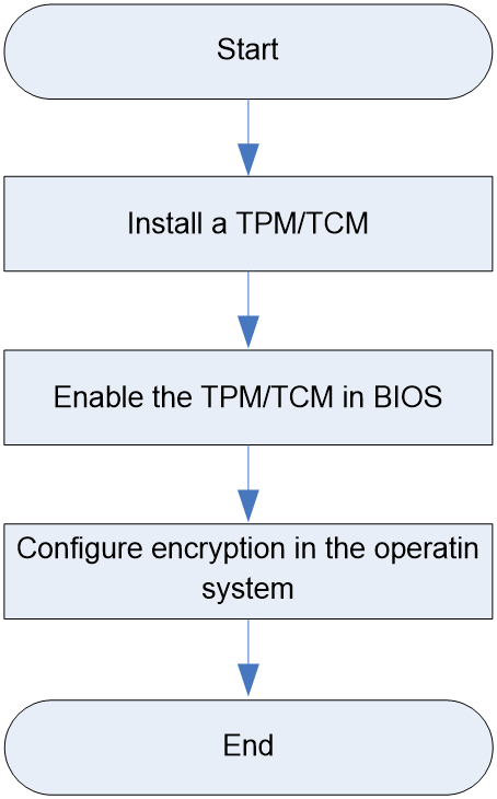
Prerequisites
· Wear antistatic clothing. Wear an ESD wrist strap and make sure it makes good skin contact and is reliably grounded. Do not wear any conductive objects, such as jewelry or watches.
· When you replace a component, examine the slot and connector for damages. Make sure the pins are not damaged (bent for example) and do not contain any foreign objects.
Installing a TPM/TCM module
Procedure
1. Power off the server. For more information, see Powering off the server.
2. Remove the server from the rack. For more information, see Removing the server.
3. Remove the access panel. Press the button on the locking lever and then lift the locking lever. The access panel automatically slides to the server rear. Lift the access panel to remove it from the server.
4. (Optional.) Remove all riser cards that hider the installation.
5. Install the TPM.
a. Press the TPM into the TPM connector on the system board.
b. Insert the rivet pin.
c. Insert the security rivet into the hole in the rivet pin and press the security rivet until it is firmly seated.
6. (Optional.) Install the removed riser cards, if any.
7. Install the access panel. Place the access panel onto the chassis, and slide the access panel to the server front until it is secured into place.
8. Install the server. For more information, see "Installing the server."
9. Connect the power cord.
10. Power on the server. For more information, see Powering on the server.
Post-installation restrictions and guidelines
· Do not remove an installed TCM or TPM. Once installed, the module becomes a permanent part of the system board.
· To replace the faulty TCM or TPM, remove the system board, and then contact H3C Support to replace the TCM or TPM and the system board.
· When installing or replacing hardware, H3C technicians cannot configure the TCM or TPM or enter the recovery key. For security reasons, only the user can perform the tasks.
· When replacing the system board, do not remove the TCM or TPM from the system board. H3C will provide a TCM or TPM with a spare system board for the replacement.
· Any attempt to remove an installed TCM or TPM from the system board breaks or disfigures the TCM or TPM security rivet. Upon locating a broken or disfigured rivet on an installed TCP or TPM, administrators should consider the system compromised and take appropriate measures to ensure the integrity of the system data.
· H3C is not liable for blocked data access caused by improper use of the TCM or TPM. For more information, see the encryption technology feature documentation provided by the operating system.
Enabling the TCM or TPM in the BIOS
1. Enter the BIOS utility. For information about how to enter the BIOS utility, see the BIOS user guide.
2. Select Advanced > Trusted Computing, and press Enter.
3. Enable the TPM or TCM. By default, the TPM and TCM are enabled for a server.
¡ If the server is installed with a TPM, perform the following steps to enable the TPM:
Select TPM State > Enabled, and press Enter.
¡ If the server is installed with a TCM, perform the following steps to enable the TPM:
Select TCM State > Enabled, and press Enter.
4. Log in to HDM to verify that the TPM/ TPM is operating correctly. For more information, see the HDM2 online help.
Configuring encryption in the operating system
For more information about this task, see the encryption technology feature documentation that came with the operating system.
The recovery key/password is generated during BitLocker setup, and can be saved and printed after BitLocker is enabled. When using BitLocker, always retain the recovery key/password. The recovery key/password is required to enter Recovery Mode after BitLocker detects a possible compromise of system integrity or firmware or hardware change.
For security purposes, follow these guidelines when retaining the recovery key/password:
· Always store the recovery key/password in multiple locations.
· Always store copies of the recovery key/password away from the server.
· Do not save the recovery key/password on the encrypted hard drive.
For more information about Microsoft Windows BitLocker drive encryption, visit the Microsoft website at http://technet.microsoft.com/en-us/library/cc732774.aspx.
Replacing a power module
Operation scenario
· The power module fails.
· Replace the power module with one of another model.
Prerequisites
· Wear antistatic clothing. Wear an ESD wrist strap and make sure it makes good skin contact and is reliably grounded. Do not wear any conductive objects, such as jewelry or watches.
· When you replace a component, examine the slot and connector for damages. Make sure the pins are not damaged (bent for example) and do not contain any foreign objects.
· Learn the power module installation guidelines. For more information, see Power supplies.
Replacement procedures
Removing a power module
The power module supports hot-swapping. If the configured power modules provide power redundancy and there is sufficient space at the rear of the server, start from the specified step. Otherwise, start from step 1.
1. Power off the server. For more information, see Powering off the server.
2. Remove the server from the rack. For more information, see Removing the server.
3. Remove the power cord from the power supply:
For power modules secured with cable ties:
a. Open the latch on the cable tie and slide the tie outward.
b. Open one end of the tie, and then remove the power cable from the tie.
c. Unplug the power cable from the power socket.
For power modules secured with Velcro straps:
d. Unwrap the Velcro strap from the cable.
e. Unplug the power cable from the power socket.
4. (Optional.) Uninstall the CMA on the side of the power supply, if any:
a. Take out cables that hinder the replacement from the cable baskets of the CMA. During this operation, make sure cables required for server operation remain connected.
b. Press the tab on the CMA connector next to the power supply and then pull the connector out.
5. Remove the power supply. Holding the power supply by its handle and pressing the retaining latch with your thumb, pull the power supply slowly out of the slot.
Installing a power module
|
|
IMPORTANT: If only one power supply is present, install the new power supply in the slot for the replaced power supply. |
1. Install the power module. Push the power supply into the slot until it snaps into place.
2. (Optional.) If the server was removed, install it. For more information, see "Installing the server."
3. (Optional.) If the power cable was disconnected, connect it.
4. (Optional.) If the server was powered off, power it on. For more information, see Powering on the server.
Replacing an NVMe VROC module
Operation scenario
· The NVMe VROC module fails.
· Replace the NVMe VROC module with one of another model.
Prerequisites
· Wear antistatic clothing. Wear an ESD wrist strap and make sure it makes good skin contact and is reliably grounded. Do not wear any conductive objects, such as jewelry or watches.
· When you replace a component, examine the slot and connector for damages. Make sure the pins are not damaged (bent for example) and do not contain any foreign objects.
Replacement procedures
Removing the NVMe VROC module
1. Power off the server. For more information, see Powering off the server.
2. Remove the server. For more information, see Removing the server.
3. Remove the access panel. Press the button on the locking lever and then lift the locking lever. The access panel automatically slides to the server rear. Lift the access panel to remove it from the server.
4. Remove the NVMe VROC module. Insert your fingers into the ring of the NVMe VROC module, grip the sides of the module, and then gently pull it upward to remove it.
Installing the NVMe VROC module
1. Install the NVMe VROC module. Align the NVMe VROC module with the connector on the system board, and gently press it downward into place.
2. Install the access panel. Place the access panel onto the chassis, and slide the access panel to the server front until it is secured into place.
3. Install the server. For more information, see "Installing the server."
4. Connect the power cord.
5. Power on the server. For more information, see Powering on the server.
6. Configure RAID for the NVMe drives. For more information, see the BIOS user guide.
Replacing the system battery
Operation scenario
By default, the system battery (model BR2032) is already installed on the server system board. Generally, the system battery has a lifespan of 3 to 5 years.
Replace the system battery in the following situations. Only BR2032 model system batteries are supported.
· Battery failure.
· Battery power is depleted, and the server no longer displays the correct date and time automatically.
|
|
NOTE: Battery failure or power depletion will cause the BIOS to revert to its default settings. After replacing the battery, if necessary, reconfigure the BIOS. See the BIOS user guide for detailed instructions. |
Prerequisites
· Wear antistatic clothing. Wear an ESD wrist strap and make sure it makes good skin contact and is reliably grounded. Do not wear any conductive objects, such as jewelry or watches.
· When you replace a component, examine the slot and connector for damages. Make sure the pins are not damaged (bent for example) and do not contain any foreign objects.
Replacement procedures
Removing the system battery
1. Power off the server. For more information, see Powering off the server.
2. Remove the server from the rack. For more information, see Removing the server.
3. Remove the access panel. Press the button on the locking lever and then lift the locking lever. The access panel automatically slides to the server rear. Lift the access panel to remove it from the server.
4. Remove the system battery. Gently lift one side of the battery upward, and it will automatically detach from the slot.
|
|
IMPORTANT: Properly dispose of the removed system battery at a designated battery disposal site. Do not throw it away with regular trash. |
Installing the system battery
1. Install the system battery.
a. Place the battery into the slot with the "+" side facing up.
b. Press the battery down to secure it in place.
2. Install the access panel. Place the access panel onto the chassis, and slide the access panel to the server front until it is secured into place.
3. Install the server. For more information, see "Installing the server."
4. Connect the power cord.
5. Power on the server. For more information, see Powering on the server.
6. Update the date and time settings in the operating system or BIOS. For detailed instructions on how to modify the date and time in the BIOS, see the BIOS user guide.
Installing and removing filler panels in each slot
Scenario
When expanding the following modules, you need to remove the corresponding filler panel; after removing the module, you need to install the corresponding filler panel.
· Drives
· LCD smart management module
· Drive backplane
· Power supplies
· Riser card
· PCIe modules
· OCP network adapter
Prerequisites
Wear antistatic clothing. Wear an ESD wrist strap and make sure it makes good skin contact and is reliably grounded. Do not wear any conductive objects, such as jewelry or watches.
Procedure
Table 46 Installing and removing filler panels for all modules
|
Item |
Procedure |
|
Remove drive filler panel |
Press the buttons on the blank in opposite directions and pull the panel outward. |
|
Install drive filler panel |
Push the filler panel into the slot. |
|
Remove drive backplanefiller panel |
From inside the chassis, use a screwdriver to firmly push on both sides of the filler panel. Once the filler panel has been pushed out a certain distance, pull it out. |
|
Install drive backplanefiller panel |
Push the filler panel into the slot until you hear a click. |
|
Remove power module filler panel |
Pull the filler panel out horizontally. |
|
Install power module filler panel |
With the "TOP" marking facing up, push the filler panel horizontally into the slot. |
|
Remove Riser card filler panel |
Lift the filler panel upward. |
|
Install Riser card filler panel |
Insert the filler panel along the bracket groove. |
|
Remove PCIe card filler panel |
Pull the filler panel out. |
|
Install PCIe card filler panel |
Insert the filler panel into the slot. |
|
Remove OCP network adapter filler panel |
Insert a screwdriver into the protruding hole on the filler panel, and then pull the filler panel out. |
|
Install OCP network adapter filler panel |
Push the filler panel horizontally into the slot. |
Internal cabling
Internal cabling guidelines
Applicable scenarios
Internal server cabling diagram can be used in the following scenarios:
· To guide cable connections after expanding or replacing components.
· To guide cable reseating if cables are loose or disconnected.
· To guide cable replacement if cable protective sleeves are damaged or cables are faulty.
Guidelines
· Cables should not be routed over removable components, such as memory modules.
· Cable routing must not obstruct the insertion or removal of other components; ensure no interference with any components inside the chassis.
· Ensure cables are routed clearly, have their own secured space, and are not pinched or scraped by the chassis structure.
· Avoid pulling on connectors when routing cables.
· When securing multiple cables with cable ties, adjust the number of cables to prevent excess tension on the ties, which could cause them to detach.
· If cables are excessively long, it is recommended to bundle them appropriately. Unused cables should be coiled and secured with cable ties.
· When connecting the hard drive data cable, a click sound indicates a secure connection.
· If connectors have protective covers, remove them before connecting the cables.
· If the built-in cable labels do not sufficiently differentiate each cable, consider adding additional tags for cable identification.
Connecting drive cables
The drive connections involve SAS/SATA data cables, NVMe data cables, power cables, and signal cables. The server supports various hard drive configurations. This section provides examples of three typical hard drive configurations to help users understand the cabling methods. For cabling methods of other hard drive configurations, contact the technical support.
|
|
NOTE: Compared to signal cables and power cables, data cables (including SAS/SATA and NVMe) are more numerous and have more complex forms. Therefore, this document provides encoding information for data cables, allowing users to determine the specific deployment of each data cable based on this encoding information. |
Front 8SFF UniBay
1. Connect the 8SFF UniBay NVMe data cable.
Figure 56 Connecting NVMe data cable
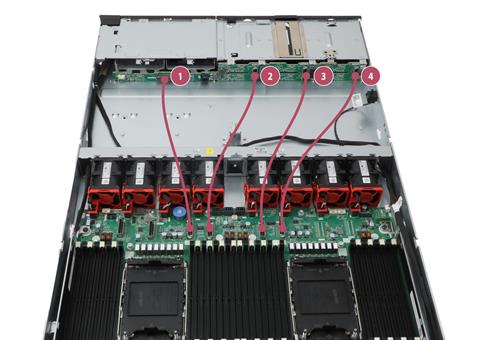
|
No. |
Cable type |
Cable code |
Cable description |
|
1 |
NVMe data cable |
0404A1PU |
Data cable connecting the front drive backplane (NVMe-A1/A2) to the system board (C1-P3A) |
|
2 |
NVMe data cable |
0404A1QT |
Data cable connecting the front drive backplane (NVMe-A3/A4) to the system board (C1-P3C) |
|
3 |
NVMe data cable |
0404A1WT |
Data cable connecting the front drive backplane (NVMe-B1/B2) to the system board (C2-P4A) |
|
4 |
NVMe data cable |
0404A1Q2 |
Data cable connecting the front drive backplane (NVMe-B3/B4) to the system board (C2-P4C) |
2. Connect the 8SFF UniBay SAS/SATA data cable.
Figure 57 Connecting 8SFF UniBay SAS/SATA data cable
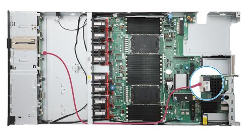
|
Cable type |
Cable code |
Cable description |
|
SAS/SATA data cable |
0404A1VB |
Data cable connecting the front drive backplane (SAS PORT) to the storage controller (C0) |
|
|
NOTE: In this configuration, the SAS/SATA data cable is used to connect to the storage controller as an example. Please refer to the actual scenario for specific cabling methods. For cabling methods of other hard drive configurations, contact the technical support. |
3. Connect the 8SFF UniBay signal cable and power cable.
Figure 58 Connecting 8SFF UniBay signal cable and power cable
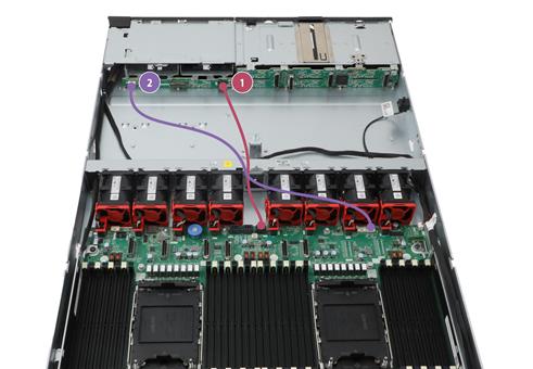
|
No. |
Cable type |
Cable description |
|
1 |
Power cable |
Data cable connecting the front drive backplane (PWR) to the system board (PWR1) |
|
2 |
Signal cable |
Data cable connecting the front drive backplane (AUX) to the system board (AUX1) |
Front 2SFF UniBay
1. Connect the front 2SFF UniBay NVMe data cable.
Figure 59 Connecting the front 2SFF UniBay NVMe data cable
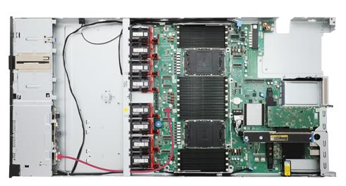
|
No. |
Cable type |
Cable code |
Cable description |
|
1 |
NVMe data cable |
0404A28T |
Data cable connecting the front 2SFF drive backplane (NVMe-A1/A2) to the system board (C1-P3A) |
2. Connect the front 2SFF UniBay SAS/SATA data cable.
Figure 60 Connecting the front 2SFF UniBay SAS/SATA data cable
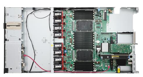
|
No. |
Cable type |
Cable code |
Cable description |
|
1 |
SAS/SATA data cable |
0404A1RN |
Data cable connecting the front 2SFFdrive backplane (SAS PORT) to the system board (SATA PORT2) |
3. Connect the front 2SFF UniBay signal cable and power cable.
Figure 61 Connecting the front 2SFF UniBay signal cable and power cable
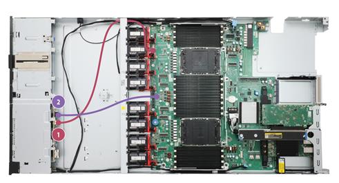
|
No. |
Cable type |
Cable description |
|
1 |
Signal cable |
Data cable connecting the front 2SFFdrive backplane (AUX) to the system board (AUX2) |
|
2 |
Power cable |
Data cable connecting the front 2SFFdrive backplane (PWR) to the system board (PWR4) |
Connecting front SATA/NVMe M.2 SSD data cables
Figure 62 Connecting front SATA/NVMe M.2 SSD data cables
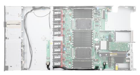
|
Cable type |
Cable code |
Cable description |
|
SAS/SATA data cable&Signal cable |
0404A1S9 |
· Data cable connecting the front M.2 SSD adapter (M.2 PORT) to the system board (M.2&SATA PORT1) · Data cable connecting the front M.2 SSD adapter (M.2 PORT) to the system board (M.2 AUX) |
Connecting riser card cables
Some riser cards can provide additional PCIe lanes to the slots on the card through interconnection with the system board. This section will introduce the cable connection methods for these riser cards. For detailed information about the slots, see "Riser cards and PCIe modules."
RC-2FHHL-1U
The RC-2FHHL-1U riser card is installed in the Riser 3 position on the server's rear panel. For riser slot numbering, see "Rear panel."
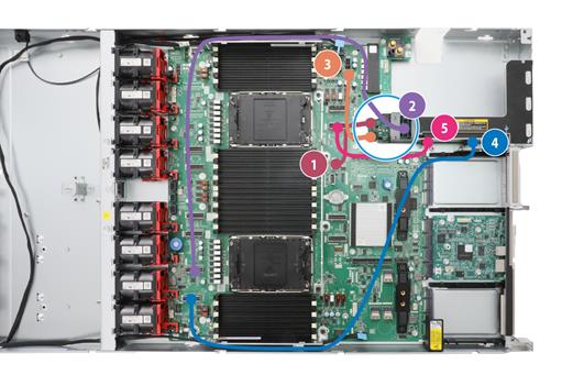
|
No. |
Cable type |
Cable code |
Cable description |
|
1 |
Signal cable |
0404A29Y |
Signal cable connecting the Riser3 (AUX) to the system board (AUX8) |
|
2 |
NVMe data cable |
0404A2CH |
Data cable connecting the Riser3 (SLOT1-B) to the system board (C1-P4C) |
|
3 |
Power cable |
0404A1WW |
Power cable connecting the Riser3 (PWR) to the system board (PWR5) |
|
4 |
NVMe data cable |
0404A1Q1 |
Data cable connecting the Riser3 (SLOT1-A) to the system board (C1-P4A) |
|
5 |
NVMe data cable |
0404A1QH |
Data cable connecting the Riser3 (SLOT2-A) to the system board (C2-P2A) |
RC-1HHHL-R4-1U-X16-G5
The RC-1HHHL-R4-1U-X16-G5 riser card is installed in the Riser 4 position on the server's front panel. For riser slot numbering, see "Rear panel."
Figure 63 Connecting the PCIe Riser card slot 4 cables
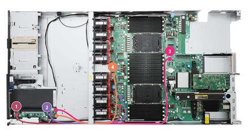
|
No. |
Cable type |
Cable code |
Cable description |
|
1 |
NVMe data cable |
0404A28U |
Data cable connecting the Riser4 (PCIe PORT1) to the system board (C1-P4A) |
|
2 |
NVMe data cable |
0404A28U |
Data cable connecting the Riser4 (PCIe PORT2) to the system board (C1-P4C) |
|
3 |
Power cable |
0404A1QV |
Power cable connecting the Riser4 (PWR) to the system board (PWR3) |
|
4 |
Signal cable |
0404A28N |
Signal cable connecting the Riser4 (AUX) to the system board (AUX8) |
RC-2FHFL-1U-SW-G6
The RC-2FHFL-1U-SW-G6 riser cards are installed in the Riser 1 and Riser 2 positions on the server's front panel. For riser slot numbering, see "Rear panel."
Figure 64 RC-2FHFL-1U-SW-G6
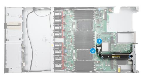
|
No. |
Cable type |
Cable |
Cable description |
|
1 |
NVMe data cable |
Riser end soldered cable |
Data cable connecting Riser1 to the system board (C1-P2A) |
|
2 |
NVMe data cable |
Riser end soldered cable |
Data cable connecting Riser2 to the system board (C1-P2C) |
Connecting power distribution board cables
The lower power distribution board controls the device power through interconnection with the upper power distribution board, fan adapter board, and expander module. This section will detail the cable connection methods for the lower power distribution board. For detailed information about the slots, see "Lower power distribution board."
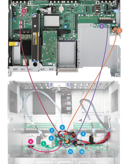
|
No. |
Cable type |
Cable code |
Cable description |
|
1 |
Signal cable |
0404A28M |
Signal cable connecting the lower power distribution board (AUX1) to the system board (AUX7) |
|
2 |
Signal cable |
0404A28W |
Signal cable connecting the lower power distribution board (AUX2) to the upper power distribution board (PDB_AUX) |
|
3 |
Power cable |
0404A28P |
Power cable connecting the lower power distribution board (RADSOK) to the upper power distribution board (RADSOK) |
|
4 |
Power cable |
0404A2B9 |
Power cable connecting the lower power distribution board (FAN_PWR) to the fan adapter module (PWR) |
|
5 |
Signal cable |
0404A1YN |
Signal cable connecting the lower power distribution board (FAN_AUX) to the fan adapter module (AUX) |
|
6 |
Signal cable |
0404A28R |
Signal cable connecting EXP1 to the lower power distribution board (EXP_AUX2) |
|
7 |
Power cable |
0404A28R |
Power cable connecting EXP1 to the lower power distribution board (EXP_ PWR 4) |
|
8 |
Power cable |
0404A28R |
Power cable connecting EXP1 to the lower power distribution board (EXP_ PWR 3) |
|
9 |
Power cable |
0404A28Y |
Power cable connecting EXP2 to the lower power distribution board (EXP_ PWR 1) |
|
10 |
Power cable |
0404A28Y |
Power cable connecting EXP2 to the lower power distribution board (EXP_ PWR 2) |
|
11 |
Signal cable |
0404A28Y |
Signal cable connecting EXP2 to the lower power distribution board (EXP_AUX1) |
Connecting inlet temperature sensor cables
Figure 65 Connecting inlet temperature sensor cables
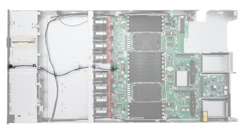
Connecting supercapacitor cables
Figure 66 Connecting supercapacitor cables
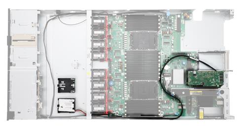
Connecting smart ear cables
Figure 67 Connecting smart ear cables
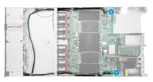
|
No. |
Cable type |
Cable description |
|
1 |
Right ear cable |
Smart ear cable connecting to the system board (RIGHT EAR) |
|
2 |
Left ear cable |
Smart ear cable connecting to the system board (LEFT EAR) |
Connecting LCD smart management module cables
Figure 68 Connecting LCD smart management module cables
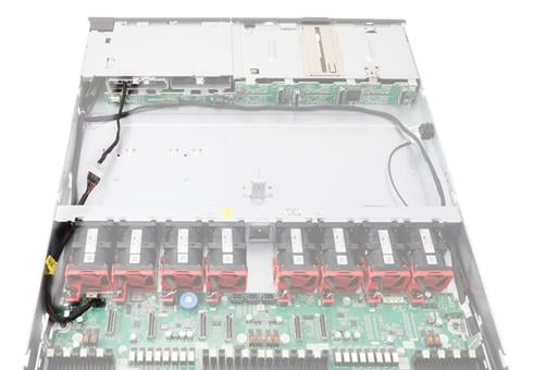
|
No. |
Cable type |
Cable code |
Cable description |
|
1 |
Signal cable |
0404A1SA |
Signal cable connecting the LCD smart management module to the system board (DIAG LCD) |
Maintenance
The following information describes the guidelines and tasks for daily server maintenance.
Guidelines
· Keep the equipment room clean and tidy. Remove unnecessary devices and objects from the equipment room. Make sure the temperature and humidity in the equipment room meet the server operating requirements.
· Regularly check the server from HDM for operating health issues.
· Keep the operating system and software up to date as required.
· Make a reliable backup plan:
¡ Back up data regularly.
¡ If data operations on the server are frequent, back up data as needed in shorter intervals than the regular backup interval.
¡ Check the backup data regularly for data corruption.
· Stock spare components on site in case replacements are needed. After a spare component is used, prepare a new one.
· Keep the network topology up to date to facilitate network troubleshooting.
Maintenance tools
The following are major tools for server maintenance:
· Thermo-hygrometer—Monitors the operating environment of the server.
· HDM and UniSystem—Monitors the operating status of the server.
Maintenance operation
This section describes the routine maintenance task operations and operation methods of the server.
Task list
Table 47 lists the routine maintenance tasks.
|
Task |
Maintenance tools |
|
/ |
|
|
Monitoring the temperature and humidity in the equipment room |
Thermo-hygrometer |
|
/ |
Observing LED status
Observe the LEDs on the front and rear panels of the server to verify that the server modules are operating correctly. For more information about LED status, see LEDs and buttons and Rear panel LEDs.
Monitoring the temperature and humidity in the equipment room
Use a thermo-hygrometer to monitor the temperature and humidity in the equipment room. The temperature and humidity in the equipment room must meet the server requirements described in Technical specifications.
Examining cable connections
Verify that the cables and power cords are correctly connected.
Guidelines
· Do not use excessive force when connecting or disconnecting cables.
· Do not twist or stretch the cables.
· Organize the cables appropriately. For more information, see Cabling guidelines.
Checklist
· The cable type is correct.
· The cables are correctly and firmly connected and the cable length is appropriate.
· The cables are in good condition and are not twisted or corroded at the connection point.
Viewing server status
To view basic information and status of the subsystems of the server, see "View device information" in H3C Servers HDM2 Online Help.
Collecting server logs
See the HDM2 user guide.
Updating firmware for the server
For the procedure of updating HDM, BIOS, or CPLD firmware, see H3C Servers Firmware Update Guide.
Troubleshooting
See the troubleshooting guide.