- Table of Contents
-
- 01-Fundamentals Configuration Guide
- 00-Preface
- 01-CLI configuration
- 02-RBAC configuration
- 03-Login management configuration
- 04-FTP and TFTP configuration
- 05-File system management configuration
- 06-Configuration file management configuration
- 07-Software upgrade configuration
- 08-ISSU configuration
- 09-GIR configuration
- 10-Automatic configuration
- 11-Preprovisioning feature configuration
- 12-Device management configuration
- 13-Tcl configuration
- 14-Python configuration
- 15-License management
- 16-Target configuration management configuration
- Related Documents
-
| Title | Size | Download |
|---|---|---|
| 12-Device management configuration | 362.25 KB |
Device management tasks at a glance
Restrictions and guidelines for configuring the system time
System time configuration tasks at a glance
Setting the system time at the CLI
Obtaining the UTC time through a time protocol
Setting the daylight saving time
Configuring delay compensation duration for obtaining time
Enabling displaying the copyright statement
Disabling password recovery capability
Setting the device operating mode
Setting the hardware resource operating mode
Setting the operating mode of the link scan feature
Configuring the clock mode of the device
Setting the port status detection timer
Enabling or disabling the hardware resource flex mode for the S9850-32H switch
Setting memory alarm thresholds
Configuring resource monitoring
Setting the temperature alarm thresholds
Disabling the notification of hardware resource alarms
Configuring hardware failure detection and protection
Specifying the actions to be taken for hardware failures
Configuring parity error logging for entries on forwarding chips
Configuring consistency error logging for software and hardware forwarding entries
Configuring uncorrectable parity error and ECC error logging for entries on forwarding chips
Setting serial numbers for fan trays
Specifying the preferred airflow direction
Verifying and diagnosing transceiver modules
Diagnosing transceiver modules
Configuring transceiver monitoring
Setting a power mode for a transceiver module
Configuring CDR on transmit or receive lanes
Restrictions and guidelines for device reboot
Rebooting the device immediately at the CLI
Restoring the factory-default configuration
Display and maintenance commands for device management configuration
Managing the device
This chapter describes how to configure basic device parameters and manage the device.
Device management tasks at a glance
All device management tasks are optional. You can perform any of the tasks in any order.
· Configuring basic parameters
¡ Configuring delay compensation duration for obtaining time
¡ Enabling displaying the copyright statement
· Configuring security parameters
Disabling password recovery capability
· Adjusting device capacities
¡ Setting the device operating mode
¡ Setting the hardware resource operating mode
¡ Setting the operating mode of the link scan feature
¡ Configuring the clock mode of the device
¡ Setting the port status detection timer
¡ Enabling or disabling the hardware resource flex mode for the S9850-32H switch
· Monitoring the device
¡ Setting memory alarm thresholds
¡ Configuring resource monitoring
¡ Setting the temperature alarm thresholds
¡ Disabling the notification of hardware resource alarms
¡ Configuring hardware failure detection and protection
¡ Configuring parity error logging for entries on forwarding chips
¡ Configuring consistency error logging for software and hardware forwarding entries
¡ Configuring uncorrectable parity error and ECC error logging for entries on forwarding chips
· Managing resources
¡ Setting serial numbers for fan trays
¡ Specifying the preferred airflow direction
¡ Verifying and diagnosing transceiver modules
¡ Configuring transceiver monitoring
¡ Setting a power mode for a transceiver module
· Maintaining the device
¡ Restoring the factory-default configuration
Configuring the device name
About this task
A device name (also called hostname) identifies a device in a network and is used in CLI view prompts. For example, if the device name is Sysname, the user view prompt is <Sysname>.
Restrictions and guidelines
On an underlay network, the device uses the device name that you have configured for it. If you do not configure a device name for the device but automated underlay network deployment is enabled, the device uses the device name assigned by the VCF fabric feature. For more information about VCF fabric, see VCF fabric configuration in Network Management and Monitoring Configuration Guide.
Procedure
1. Enter system view.
system-view
sysname sysname
By default, the device name is H3C.
Configuring the system ID
About this task
You can use the system ID to indicate the position or functionality of the device or any other information.
Procedure
1. Enter system view.
system-view
2. Configure the system ID.
sysid system-id
By default, the device does not have a system ID.
Configuring the system time
About the system time
Correct system time is essential to network management and communication. Configure the system time correctly before you run the device on the network.
The device can use one of the following methods to obtain the system time:
· Uses the locally set system time, and then uses the clock signals generated by its built-in crystal oscillator to maintain the system time.
· Periodically obtains the UTC time from an NTP or PTP source, and uses the UTC time, time zone, and daylight saving time to calculate the system time. For more information about NTP and PTP, see Network Management and Monitoring Configuration Guide.
The system time calculated by using the UTC time from a time source is more precise.
Restrictions and guidelines for configuring the system time
After you execute the clock protocol none command, the clock datetime command determines the system time, whether or not the time zone or daylight saving time has been configured.
If you configure or change the time zone or daylight saving time after the device obtains the system time, the device recalculates the system time. To view the system time, execute the display clock command.
System time configuration tasks at a glance
To configure the system time, perform the following tasks:
1. Configuring the system time
Choose one of the following tasks:
¡ Setting the system time at the CLI
¡ Obtaining the UTC time through a time protocol
2. (Optional.) Setting the time zone
Make sure each network device uses the time zone of the place where the device resides.
3. (Optional.) Setting the daylight saving time
Make sure each network device uses the daylight saving time parameters of the place where the device resides.
Setting the system time at the CLI
1. Enter system view.
system-view
2. Configure the device to use the local system time.
clock protocol none
By default, the device uses the NTP time source.
If you execute the clock protocol command multiple times, the most recent configuration takes effect.
3. Return to user view.
quit
4. Set the local system time.
clock datetime time date
By default, the system time is UTC time 00:00:00 01/01/2011.
|
|
CAUTION: Change of the system time affects execution of system time-related features (such as scheduled tasks) and cooperative operation with other devices (such as log reporting and statistics collection). Before using this command, make sure you understand its impact on the live network. |
Obtaining the UTC time through a time protocol
1. Enter system view.
system-view
2. Specify the system time source.
clock protocol { ntp | ptp }
By default, the device uses the NTP time source.
If you execute this command multiple times, the most recent configuration takes effect.
3. Configure time protocol parameters.
For more information about NTP and PTP configuration, see Network Management and Monitoring Configuration Guide.
Setting the time zone
1. Enter system view.
system-view
2. Set the time zone.
clock timezone zone-name { add | minus } zone-offset
By default, the system uses the UTC time zone.
Setting the daylight saving time
1. Enter system view.
system-view
2. Set the daylight saving time.
clock summer-time name start-time start-date end-time end-date add-time
By default, the daylight saving time is not set.
Configuring delay compensation duration for obtaining time
About this task
For devices that obtains time through coaxial cables or external antennas, the time obtained by the device clock chip will experience a delay. The length of the coaxial cable or external antenna determines the length of this delay. This feature configures the delay compensation duration for the device's time obtaining. The compensation duration needs to be determined based on the actual length of the coaxial cable or external antenna.
Restrictions and guidelines
Before configuring this feature, determine the delay compensation duration based on the actual length of the external antenna or coaxial cable.
Procedure
1. Enter system view.
system-view
2. Configure the delay compensation duration for obtaining time.
clock delay-compensation { 1pps | gps } timer
By default, the delay compensation duration for obtaining time is 0.
Enabling displaying the copyright statement
About this task
This feature enables the device to display the copyright statement in the following situations:
· When a Telnet or SSH user logs in.
· When a console user quits user view. This is because the device automatically tries to restart the user session.
If you disable displaying the copyright statement, the device does not display the copyright statement in any situations.
Procedure
1. Enter system view.
system-view
2. Enable displaying the copyright statement.
copyright-info enable
By default, displaying the copyright statement is enabled.
Configuring banners
About this task
Banners are messages that the system displays when a user logs in.
The system supports the following banners:
· Legal banner—Appears after the copyright statement.
· Message of the Day (MOTD) banner—Appears after the legal banner and before the login banner.
· Login banner—Appears only when password or scheme authentication is configured.
· Shell banner—Appears when a user accesses user view.
The system displays the banners in the following order: legal banner, MOTD banner, login banner, and shell banner.
Banner input methods
You can configure a banner by using one of the following methods:
· Input the entire command line in a single line.
The banner cannot contain carriage returns. The entire command line, including the command keywords, the banner, and the delimiters, can have a maximum of 511 characters. The delimiters for the banner can be any printable character but must be the same. You cannot press Enter before you input the end delimiter.
For example, you can configure the shell banner "Have a nice day." as follows:
<System> system-view
[System] header shell %Have a nice day.%
· Input the command line in multiple lines.
The banner can contain carriage returns. A carriage return is counted as two characters.
To input a banner configuration command line in multiple lines, use one of the following methods:
¡ Press Enter after the final command keyword, type the banner, and end the final line with the delimiter character %. The banner plus the delimiter can have a maximum of 1999 characters.
For example, you can configure the banner "Have a nice day." as follows:
<System> system-view
[System] header shell
Please input banner content, and quit with the character '%'.
Have a nice day.%
¡ After you type the final command keyword, type any printable character as the start delimiter for the banner and press Enter. Then, type the banner and end the final line with the same delimiter. The banner plus the end delimiter can have a maximum of 1999 characters.
For example, you can configure the banner "Have a nice day." as follows:
<System> system-view
[System] header shell A
Please input banner content, and quit with the character 'A'.
Have a nice day.A
¡ After you type the final command keyword, type the start delimiter and part of the banner. Make sure the final character of the final string is different from the start delimiter. Then, press Enter, type the rest of the banner, and end the final line with the same delimiter. The banner plus the start and end delimiters can have a maximum of 2002 characters.
For example, you can configure the banner "Have a nice day." as follows:
<System> system-view
[System] header shell AHave a nice day.
Please input banner content, and quit with the character 'A'.
A
Procedure
1. Enter system view.
system-view
2. Configure the legal banner.
header legal text
3. Configure the MOTD banner.
header motd text
4. Configure the login banner.
header login text
5. Configure the shell banner.
header shell text
Disabling password recovery capability
About this task
Password recovery capability controls console user access to the device configuration and SDRAM from BootWare menus. For more information about BootWare menus, see the release notes.
If password recovery capability is enabled, a console user can access the device configuration without authentication to configure a new password.
If password recovery capability is disabled, console users must restore the factory-default configuration before they can configure new passwords. Restoring the factory-default configuration deletes the next-startup configuration files.
To enhance system security, disable password recovery capability.
Restrictions and guidelines
To access the device configuration without authentication, you must connect to the master device and access the BootWare menu during the device startup.
Procedure
1. Enter system view.
system-view
2. Disable password recovery capability.
undo password-recovery enable
By default, password recovery capability is enabled.
Setting the device operating mode
About this task
Supported features and feature specifications vary by device operating mode.
The device can operate in one of the following modes:
· advance—Advanced mode. FC and FCoE are supported only in this mode.
· standard—Standard mode.
Restrictions and guidelines
A change to the device operating mode takes effect after a device reboot.
Procedure
1. Enter system view.
system-view
2. Set the device operating mode.
system-working-mode { advance | standard }
By default, the device operates in standard mode.
Setting the hardware resource operating mode
About this task
The device supports multiple hardware resource operating modes. The capacities of the MAC address table, ARP and ND tables, and IPv4 and IPv6 routing tables vary by hardware resource operating mode.
The routing table capacities also vary by the hardware-resource routing-mode ipv6-128 command and the uRPF feature. Table 1 lists the capacities of the routing tables when the uRPF feature is disabled. When the uRPF feature is enabled, the capacities of the routing tables decrease by 50%. After the hardware-resource routing-mode ipv6-128 command is executed, the device supports IPv6 routes with prefixes longer than 64 bits. For information about this command, see Layer 3—IP Routing Command Reference. For information about uRPF, see Security Configuration Guide.
The MAC address table, ARP and ND tables, and IPv4 and IPv6 routing tables share the same storage space. Table 1 lists the maximum capacities of the tables in various scenarios. Not all the maximum capacities can be reached at the same time.
The IPv4 and IPv6 routing table capacities can be reached at the same time only if the device operates in dual-stack mode and the hardware-resource routing-mode ipv6-128 command is executed.
The cells under IPv6-64 in the table show the routing table capacities when the hardware-resource routing-mode ipv6-128 command is not executed. The cells under IPv6-128 in the table show the routing table capacities after the hardware-resource routing-mode ipv6-128 command is executed. The following terms in the table represent the IPv6 address prefix length ranges: 0-64, 65-127, and 128.
In the case of IPv6-64 (65-127), the IPv6 routing table capacity is fixed at 0.
Table 1 Capacities of the tables in hardware resource operating modes
|
Mode |
MAC address table |
ARP/ND table |
Routing tables (IPv6-64) |
Routing tables (IPv6-128) |
|||||
|
IPv4 |
IPv6 |
IPv4 |
IPv6 |
||||||
|
0-64 |
128 |
0-64 |
65-127 |
128 |
|||||
|
NORMAL |
96K |
80K/40K |
162K |
80K |
40K |
160K |
65K |
65K |
73K |
|
MAC |
288K |
16K/8K |
32K |
16K |
8K |
32K |
8K |
4K |
8K |
|
ROUTING |
32K |
16K/8K |
324K |
165K |
8K |
324K |
73K |
73K |
73K |
|
ARP |
32K |
272K/136K |
32K |
16K |
136K |
32K |
8K |
4K |
143K |
|
DUAL-STACK |
32K |
16K/8K |
324K |
165K |
8K |
87K |
86K |
86K |
86K |
|
EM |
32K |
16K/8K |
32K |
16K |
8K |
32K |
8K |
4K |
8K |
Restrictions and guidelines
A hardware resource operating mode change takes effect after you save the running configuration and reboot the device. Before rebooting the device, make sure you know the possible impact on the network.
The table capacities are the maximum sizes in theory. The actual capacities might be different.
Procedure
1. Enter system view.
system-view
2. Set the hardware resource operating mode.
hardware-resource switch-mode { ARP | DUAL-STACK | EM | MAC | NORMAL | ROUTING }
By default, the hardware resource operating mode is NORMAL.
Setting the operating mode of the link scan feature
About this task
The link scan feature in hardware mode can more quickly detect port status changes, which accelerates network convergence.
Restrictions and guidelines
Only the devices with the same link scan operating mode can set up an IRF fabric.
The S6850-2C and S9850-4C devices that are installed with the LSWM124XG2QFC or LSWM116FC subcard do not support the hardware mode. If the link scan feature operates in hardware mode, the operating mode of the link scan feature will automatically change to software after you install the LSWM124XG2QFC or LSWM116FC subcard to the device.
The LSWM124XGT2Q interface card does not support specifying the operating mode of the link scan feature.
After you configure this feature, save the configuration and restart the device for the configuration to take effect.
Prcoedure
1. Enter system view.
system-view
2. Set the operating mode of the link scan feature.
hardware-resource linkscan-mode { hardware | software }
By default, the link scan feature operates in software mode.
Configuring the clock mode of the device
Restrictions and guidelines
If the clock mode at the current device startup is hpet, the new clock mode configured by this feature will take effect on the next device startup. For the configuration to take effect, save the configuration and restart the device.
If the clock mode at the current device startup is tsc, the clock mode configured by this feature will take effect immediately no matter whether the new clock mode is tsc or hpet. However, a device restart prompt might still appear, which can be ignored. To ensure that the newly configured clock mode still takes effect on the next device startup, save the configuration before restarting the device.
This feature is only supported on early devices. If this feature cannot be configured on a standalone device, the device does not support this feature.
Two devices with different clock modes cannot form an IRF fabric. The clock mode of devices is typically tsc, but early devices might have a different clock mode. You can configure this feature on early devices to ensure that the clock modes of the devices for IRF setup are the same. If an IRF fabric has been set up for early devices and new devices, these early devices do not support changing the clock mode.
To obtain the clock mode at the current and next device startup for early devices, execute the display hardware-resource clock-mode command:
· If the Current field in the output displays tsc, the Next field displays the current clock mode of the device, which is the same as the clock mode at the next device startup.
· If the Current field in the output displays hpet, the Current field displays the current clock mode of the device, which is the same as the clock mode at the current device startup.
Procedure
1. Enter system view.
system-view
2. Specify the clock mode of the device.
hardware-resource clock-mode { hpet | tsc }
If the device does not support this command, the default clock mode is tsc. If the device supports this command, you can execute the display hardware-resource clock-mode command to obtain the default clock mode.
Setting the port status detection timer
About this task
The device starts a port status detection timer when a port is shut down by a protocol. If the port has been in down state before the timer expires, the device will set the port status to the port's physical status.
Procedure
1. Enter system view.
system-view
2. Set the port status detection timer.
shutdown-interval time
The default setting is 30 seconds.
Enabling or disabling the hardware resource flex mode for the S9850-32H switch
About this task
You can split interface 31 on the S9850-32H switch into breakout interfaces as follows after enabling the hardware resource flex mode for the device.
· Use the using fiftygige command in 100GE interface view to split the 100GE interface into two 50GE interfaces.
· Use the using twenty-fivegige command in 100GE interface view to split the 100GE interface into four 25GE interfaces.
· Use the using tengige command in 100GE interface view to split the 100GE interface into four 10GE interfaces.
· Use the using hundredgige command in 50GE, 25GE, or 10GE breakout interface view to combine the breakout interfaces into one 100GE interface.
For more information about the using fiftygige, using twenty-fivegige, using tengige, and using hundredgige commands, see Ethernet interface commands in Layer 2—Ethernet Interface Command Reference.
Hardware and feature compatibility
This feature is supported only on the S9850-32H switch.
Restrictions and guidelines
In hardware resource flex mode, SFP interface 34 will be deleted, and the switch does not support NetStream.
In an IRF fabric, make sure the member devices have the same hardware resource flex mode enabling status.
For this configuration to take effect, you must reboot the device.
Procedure
1. Enter system view.
system-view
2. Enable or disable the hardware resource flex mode for the device.
hardware-resource flex-mode { disable | enable }
By default, the hardware resource flex mode is disabled.
Monitoring CPU usage
About this task
To monitor CPU usage, the device performs the following operations:
· Samples CPU usage at 1-minute intervals, and compares the samples with CPU usage thresholds to identify the CPU usage status and send alarms or notifications accordingly.
· Samples and saves CPU usage at a configurable interval if CPU usage tracking is enabled. You can use the display cpu-usage history command to display the historical CPU usage statistics in a coordinate system.
The device supports the following CPU usage thresholds:
· Minor threshold—If the CPU usage increases to or above the minor threshold but is less than the severe threshold, the CPU usage enters minor alarm state. The device sends minor alarms periodically until the CPU usage increases above the severe threshold or the minor alarm is removed.
· Severe threshold—If the CPU usage increases above the severe threshold, the CPU usage enters severe alarm state. The device sends severe alarms periodically until the severe alarm is removed.
· Recovery threshold—If the CPU usage decreases below the recovery threshold, the CPU usage enters recovered state. The device sends a recovery notification.
CPU usage alarms and notifications can be sent to NETCONF, SNMP, and the information center to be encapsulated as NETCONF events, SNMP traps and informs, and log messages. For more information, see NETCONF, SNMP, and information center in Network Management and Monitoring Configuration Guide.
Figure 1 CPU alarms and alarm-removed notifications

Procedure
1. Enter system view.
system-view
2. Set the CPU usage alarm thresholds.
monitor cpu-usage threshold severe-threshold { minor-threshold minor-threshold recovery-threshold recovery-threshold [ slot slot-number [ cpu cpu-number ] ] | slot slot-number cpu cpu-number [ core core-id-list ] }
The default settings are as follows:
¡ Severe CPU usage alarm threshold—99%.
¡ Minor CPU usage alarm threshold—90%.
¡ CPU usage recovery threshold—60%.
|
|
CAUTION: If you set the severe CPU usage alarm threshold to a too low value, the device will reach the threshold easily. Normal service processing will be affected. |
3. Set CPU usage alarm resending intervals.
monitor resend cpu-usage { minor-interval minor-interval | severe-interval severe-interval } * [ slot slot-number [ cpu cpu-number ] ]
By default, the minor alarm resending interval is 300 seconds and the severe alarm resending interval is 60 seconds.
4. Set the sampling interval for CPU usage tracking.
monitor cpu-usage interval interval [ slot slot-number [ cpu cpu-number ] ]
By default, the sampling interval for CPU usage tracking is 1 minute.
5. Enable CPU usage tracking.
monitor cpu-usage enable [ slot slot-number [ cpu cpu-number ] ]
By default, CPU usage tracking is enabled.
6. (Optional.) Enable periodic CPU usage logging.
monitor cpu-usage logging interval interval-time
By default, periodic CPU usage logging is disabled.
Setting memory alarm thresholds
About this task
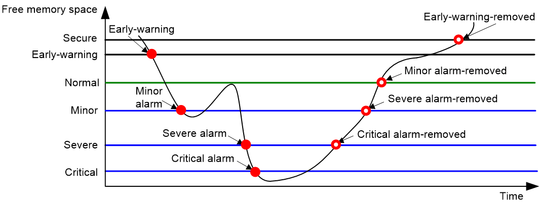
To ensure correct operation and improve memory efficiency, the system monitors the amount of free memory space in real time. If the amount of free memory space reaches the minor, severe, or critical alarm threshold, the system issues an alarm to affected service modules and processes.
The system can also issue an early warning to warn you of an approaching insufficient-memory condition.
You can use the display memory command to display memory usage information.
As shown in the following table and figure, the system supports these free-memory thresholds:
· Sufficient-memory threshold.
· Early-warning threshold.
· Normal state threshold.
· Minor alarm threshold.
· Severe alarm threshold.
· Critical alarm threshold.
Table 2 Memory alarm notifications and memory alarm-removed notifications
|
Notification |
Triggering condition |
Remarks |
|
Early-warning notification |
The amount of free memory space decreases below the early-warning threshold. |
After generating and sending an early-warning notification, the system does not generate and send any additional early-warning notifications until the early warning is removed. |
|
Minor alarm notification |
The amount of free memory space decreases below the minor alarm threshold. |
After generating and sending a minor alarm notification, the system does not generate and send any additional minor alarm notifications until the minor alarm is removed. |
|
Severe alarm notification |
The amount of free memory space decreases below the severe alarm threshold. |
After generating and sending a severe alarm notification, the system does not generate and send any additional severe alarm notifications until the severe alarm is removed. |
|
Critical alarm notification |
The amount of free memory space decreases below the critical alarm threshold. |
After generating and sending a critical alarm notification, the system does not generate and send any additional critical alarm notifications until the critical alarm is removed. |
|
Critical alarm-removed notification |
The amount of free memory space increases above the severe alarm threshold. |
N/A |
|
Severe alarm-removed notification |
The amount of free memory space increases above the minor alarm threshold. |
N/A |
|
Minor alarm-removed notification |
The amount of free memory space increases above the normal state threshold. |
N/A |
|
Early-warning-removed notification |
The amount of free memory space increases above the sufficient-memory threshold. |
N/A |
Figure 2 Memory alarm notifications and alarm-removed notifications
Restrictions and guidelines
If a memory alarm occurs, delete unused configuration items or disable some features to increase the free memory space. Because the memory space is insufficient, some configuration items might not be able to be deleted.
The system reboots the device if one of the following conditions is met:
· After a critical alarm occurs, the remaining free-memory value has been smaller than the critical alarm threshold for 30 seconds.
· The interval between two consecutive critical alarms is shorter than 30 seconds.
· The critical alarm has occurred three times within three minutes.
· After a critical alarm occurs, the system will periodically sample free memory space and predict if the free memory space will be exhausted within 30 seconds. If the prediction result indicates that the free memory space will be exhausted within 30 seconds, the system will reboot the device.
If the minor, severe, and critical alarm thresholds are the same, the device will generate notifications and automatically restart after the free memory space reaching these thresholds.
Once the free memory space reaches the early warning, minor, severe, or critical alarm threshold, the device will display the current memory usage information when you log in to the device through console or Telnet login, or execute every command.
After you configure this feature, if the amount of the free memory space reaches an alarm threshold, the system does not support creating a segment or entering its view. However, an existing microsegment will not be affected by this feature.
After you configure this feature, if the amount of the free memory space reaches the minor alarm threshold, the device cannot generate an asymmetric key pair through the public-key local create command. For more information, see PKI configuration in Security Configuration Guide.
Procedure
1. Enter system view.
system-view
2. Set the memory usage threshold.
memory-threshold [ slot slot-number [ cpu cpu-number ] ] usage memory-threshold
By default, the memory usage threshold is 100%.
3. Set the free-memory thresholds.
memory-threshold [ slot slot-number [ cpu cpu-number ] ] [ ratio ] minor minor-value severe severe-value critical critical-value normal normal-value [ early-warning early-warning-value secure secure-value ]
The default settings are as follows:
¡ Minor alarm threshold—224 MB.
¡ Severe alarm threshold—224 MB.
¡ Critical alarm threshold—224 MB.
¡ Normal state threshold—496 MB.
¡ Early-warning threshold—512 MB.
¡ Sufficient-memory threshold—576 MB.
4. Set memory depletion alarm resending intervals.
monitor resend memory-threshold { critical-interval critical-interval | early-warning-interval early-warning-interval | minor-interval minor-interval | severe-interval severe-interval } * [ slot slot-number [ cpu cpu-number ] ]
The following are the default settings:
¡ Early warning resending interval—1 hour.
¡ Minor alarm resending interval—12 hours.
¡ Severe alarm resending interval—3 hours.
¡ Critical alarm resending interval—1 hour.
5. (Optional.) Enable periodic memory usage logging.
monitor memory-usage logging interval interval-time
By default, periodic memory usage logging is disabled.
Monitoring DMA memory
About this task
To ensure correct operation of services that use Direct Memory Access (DMA) memory, the system monitors the amount of free DMA memory space regularly. If the amount of free DMA memory space decreases to or below the alarm threshold, the device restarts.
Procedure
1. Enter system view.
system-view
2. Set the DMA memory thresholds.
memory-threshold dma [ slot slot-number [ cpu cpu-number ] ] [ ratio ] critical critical-value normal normal-value
By default, the DMA memory alarm threshold is 2048 KB, and the normal state threshold is 4096 KB.
Configuring resource monitoring
About this task
The resource monitoring feature enables the device to monitor the available amounts of types of resources, for example, the space for ARP entries. The device samples the available amounts periodically and compares the samples with resource depletion thresholds to identify the resource depletion status.
The device supports a minor resource depletion threshold and a severe resource depletion threshold for each supported resource type.
· If the available amount is equal to or less than the minor resource depletion threshold but greater than the severe resource depletion threshold, the resource type is in minor alarm state.
· If the available amount is equal to or less than the severe resource depletion threshold, the resource type is in severe alarm state.
· If the available amount increases above the minor resource depletion threshold, the resource type is in recovered state.
When a resource type enters severe alarm state, the device issues a severe alarm. If the resource type stays in severe alarm state, the device resends severe alarms periodically.
When a resource type enters minor alarm state, the device issues a minor alarm. If the resource type stays in minor alarm state or changes from severe alarm state to minor alarm state, the device identifies whether resending of minor resource depletion alarms is enabled. If the feature is disabled, the device does not issue additional minor alarms. If the feature is enabled, the device resends minor alarms periodically.
Resource depletion alarms can be sent to NETCONF, SNMP, and the information center to be encapsulated as NETCONF events, SNMP traps and informs, and log messages. For more information, see NETCONF, SNMP, and information center in Network Management and Monitoring Configuration Guide.
Figure 3 Resource depletion alarms and alarm-removed notifications

Procedure
1. Enter system view.
system-view
2. Set resource depletion thresholds.
resource-monitor resource resource-name slot slot-number cpu cpu-number by-percent minor-threshold minor-threshold severe-threshold severe-threshold
The default settings vary by resource type. Use the display resource-monitor command to display the resource depletion thresholds.
3. Specify destinations for resource depletion alarms.
resource-monitor output { netconf-event | snmp-notification | syslog } *
By default, resource depletion alarms are sent to NETCONF, SNMP, and the information center.
4. Enable resending of minor resource depletion alarms.
resource-monitor minor resend enable
By default, resending of minor resource depletion alarms is enabled.
Setting the temperature alarm thresholds
About this task
The device monitors its temperature based on the following thresholds:
· Low-temperature threshold.
· High-temperature warning threshold.
· High-temperature alarming threshold.
When the device temperature drops below the low-temperature threshold or reaches the high-temperature warning or alarming threshold, the device performs the following operations:
· Sends log messages and traps.
· Sets LEDs on the device panel.
Procedure
1. Enter system view.
system-view
2. Configure the temperature alarm thresholds.
temperature-limit slot slot-number hotspot sensor-number lowlimit warninglimit [ alarmlimit ]
The defaults vary by temperature sensor model. To view the defaults, execute the undo temperature-limit and display environment commands in turn.
The high-temperature alarming threshold must be higher than the high-temperature warning threshold, and the high-temperature warning threshold must be higher than the low-temperature threshold.
Disabling the notification of hardware resource alarms
About this task
Perform this task to disable the notification of hardware resource alarms.
Procedure
1. Enter system view.
system-view
2. Disable the notification of hardware resource alarms.
hardware-alarm { syslog | trap } resource-type { all | board | bus | chip-channel | chip-port | device | disk | fan | interface | power | subcard | transceiver | voltage } disable
By default, the notification of all hardware resource alarms is enabled.
Configuring hardware failure detection and protection
The device can automatically detect hardware failures on components, the device, and the forwarding plane, and take actions in response.
Specifying the actions to be taken for hardware failures
About this task
The device can take the following actions in response to hardware failures:
· isolate—Performs the following tasks as appropriate to reduce impact from the failures:
¡ Shuts down the relevant ports.
¡ Prohibits loading software for the device.
¡ Powers off the device.
· reset—Restarts the relevant components or the device to recover from failures.
· warning—Sends traps to report the failures.
Procedure
1. Enter system view.
system-view
2. Specify the action to be taken in response to a type of hardware failures.
hardware-failure-detection { board | chip | forwarding } { off | isolate | reset | warning }
By default, the system takes the action of reset in response to hardware failures.
Configuring parity error logging for entries on forwarding chips
About this task
The device automatically detects parity errors in entries on forwarding chips. The parity error logging feature collects parity error statistics periodically, and generates a log message if the number of parity errors exceeds the logging threshold.
Procedure
1. Enter system view.
system-view
2. Set the parity error statistics period for entries on forwarding chips.
parity-error monitor period value
The default parity error statistics period is 600 seconds for entries on forwarding chips.
3. Set the parity error logging threshold for entries on forwarding chips.
parity-error monitor threshold value
The default parity error logging threshold is 5000 for entries on forwarding chips.
4. Enable parity error logging for entries on forwarding chips.
parity-error monitor log enable
By default, parity error logging is disabled for entries on forwarding chips.
Configuring consistency error logging for software and hardware forwarding entries
About this task
To forward packets, the device generates hardware forwarding entries in forwarding chips and software forwarding entries in memory at the same time. The device automatically detects whether the hardware forwarding entries and the software forwarding entries are consistent.
The consistency error logging for software and hardware forwarding entries enables the device to collect statistics for consistency errors periodically. If the number of consistency errors reaches or exceeds the logging threshold, the device generates a log message.
Procedure
1. Enter system view.
system-view
2. Set the logging threshold for consistency errors between software and hardware forwarding entries.
parity-error consistency-check threshold value
The default logging threshold is 10.
3. Enable consistency error logging for software and hardware forwarding entries.
parity-error consistency-check log enable
By default, consistency error logging is disabled for software and hardware forwarding entries.
Configuring uncorrectable parity error and ECC error logging for entries on forwarding chips
About this task
The device automatically detects parity errors and ECC errors in entries on forwarding chips and tries to correct the error when an error is detected. The uncorrectable parity error and ECC error logging feature enables the device to collect statistics for uncorrectable parity errors and ECC errors periodically. If the number of uncorrectable parity errors and ECC errors reaches or exceeds the logging threshold, the device generates a log message.
Uncorrectable parity errors and ECC errors in entries on forwarding chips might affect system services. To remove the errors from the entries on forwarding chips, you can enable automatic system reboot upon generation of an uncorrectable parity error and ECC error log.
Procedure
1. Enter system view.
system-view
2. Set the statistics period for uncorrectable parity error and ECC errors for entries on forwarding chips.
parity-error unrecoverable period value
By default, the statistics period for uncorrectable parity error and ECC errors for entries on forwarding chips is 600 seconds.
3. Set the logging threshold for uncorrectable parity errors and ECC errors for entries on forwarding chips.
parity-error unrecoverable threshold value
By default, the logging threshold for uncorrectable parity errors and ECC errors for entries on forwarding chips is 1.
4. Enable uncorrectable parity error and ECC error logging for entries on forwarding chips.
parity-error unrecoverable log enable
By default, uncorrectable parity error and ECC error logging is enabled for entries on forwarding chips
5. (Optional.) Enable automatic system reboot upon generation of an uncorrectable parity error and ECC error log.
parity-error unrecoverable reboot
By default, the device reboots automatically upon generation of an uncorrectable parity error and ECC error log.
Setting serial numbers for fan trays
About this task
After you set serial numbers for fan trays correctly, the display device manuinfo and display device manuinfo fan commands can display serial numbers and manufacturing dates of fan trays.
Hardware and feature compatibility
This feature is not supported on the S6805 and S6825 switch series.
Restrictions and guidelines
To set the serial number for a fan tray, read the label on the fan tray for its serial number and enter the correct serial number in the command.
The display device manuinfo and display device manuinfo fan commands display NONE for the serial number and manufacturing date fields of a fan tray in the following situations:
· The fan tray does not have a serial number configured.
· The configured serial number is incorrect.
Procedure
1. Enter system view.
system-view
2. Set the serial number for a fan tray.
download manuinfo slot slot-number fan fan-id serial-num serial-number
By default, fan trays do not have serial numbers configured.
Specifying the preferred airflow direction
About this task
Two fan tray models are available for the device. One model has air flow from the port side to the power module side. The other model has air flow from the power module side to the port side.
A fan tray can operate effectively only when it uses the same air flow direction as the ventilation system in the equipment room. The preferred airflow direction must also be the same.
This feature specifies the preferred airflow direction, but does not adjust the airflow direction. If a fan tray is not operating correctly or its airflow direction is different from the preferred airflow direction, the system sends traps and logs. You must replace the fan tray.
Procedure
1. Enter system view.
system-view
2. Specify the preferred airflow direction.
fan prefer-direction slot slot-number { port-to-power | power-to-port }
By default, the preferred airflow direction is from the port side to the power supply side.
Verifying and diagnosing transceiver modules
Verifying transceiver modules
About this task
You can use one of the following methods to verify the genuineness of a transceiver module:
· Display the key parameters of a transceiver module, including its transceiver type, connector type, central wavelength of the transmit laser, transfer distance, and vendor name.
· Display its electronic label. The electronic label is a profile of the transceiver module and contains the permanent configuration, including the serial number, manufacturing date, and vendor name. The data was written to the transceiver module or the device's storage component during debugging or testing of the transceiver module or device.
The device regularly checks transceiver modules for their vendor names. If a transceiver module does not have a vendor name or the vendor name is not H3C, the device repeatedly outputs traps and log messages. For information about logging rules, see Network Management and Monitoring Configuration Guide.
Procedure
To verify transceiver modules, execute the following commands in any view:
· Display the key parameters of transceiver modules.
display transceiver interface [ interface-type interface-number ]
· Display the electrical label information of transceiver modules.
display transceiver manuinfo interface [ interface-type interface-number ]
Diagnosing transceiver modules
About this task
The device provides the following diagnosis functions for transceiver modules:
The device provides the alarm and digital diagnosis functions for transceiver modules. When a transceiver module fails or is not operating correctly, you can perform the following tasks:
· Display transceiver alarms. The device check the alarms that exist on transceiver modules to identify the fault source.
· Display the current values of the digital diagnosis parameters on transceiver modules, that is, digital diagnosis functions for transceiver modules. The device can examine the key parameters monitored by the digital diagnosis function, including the temperature, voltage, laser bias current, TX power, and RX power.
· Display diagnosis information in an eye diagram. This function simulates the quality of data transmission from professional testing instruments. It obtains the sampling values of received data on chips and outputs the diagnostic results of transceiver modules in an eye diagram. This facilitates users in analyzing and evaluating the data transmission quality of transceiver modules.
Procedure
To diagnose transceiver modules, execute the following commands in any view:
· Display transceiver alarms.
display transceiver alarm interface [ interface-type interface-number ]
· Display the current values of the digital diagnosis parameters on transceiver modules.
display transceiver diagnosis interface [ interface-type interface-number ]
· Display diagnosis information for transceiver modules in an eye diagram.
display transceiver eyediagram-diagnosis interface [ interface-type interface-number ]
Configuring transceiver monitoring
About this task
After transceiver monitoring is enabled, the device samples the parameters of transceiver modules periodically, including the input power and output power of transceiver modules. If a sampled value reaches the alarm threshold, the device generates a log to notify users.
Restrictions and guidelines
Procedure
1. Enter system view.
system-view
2. Set the transceiver monitoring interval.
transceiver monitor interval interval
By default, the transceiver monitoring interval is 600 seconds.
3. Enable transceiver monitoring.
transceiver monitor enable
By default, transceiver monitoring is disabled.
Setting a power mode for a transceiver module
About this task
A transceiver module generally operates in high power mode. If the transceiver module does not work for a long time, you can switch the transceiver module to low power mode to reduce power consumption. In low power mode, the transceiver module does not transmit signals. To transmit signals, set high power mode for the transceiver module.
Restrictions and guidelines
The power mode setting is saved in a register on the transceiver module. It is not saved to the configuration file.
This feature is supported only on the QSFP transceiver modules.
Procedure
1. Enter system view.
system-view
2. Enter Ethernet interface view.
interface interface-type interface-number
3. Set a power mode for a transceiver module.
transceiver power-mode { high | low }
By default, the high power mode is specified for a transceiver module.
Configuring CDR on transmit or receive lanes
About this task
Enabling clock and data recovery (CDR) can reduce the jitter to improve transmission performance, and disabling CDR degrades transmission performance. Both the enable and disable operations might cause oscillation on device ports.
Restrictions and guidelines
This feature is supported only on a QSFP transceiver module.
This configuration is saved in a register on the transceiver module. It is not saved to the configuration file.
Procedure
1. Enter system view.
system-view
2. Enter Ethernet interface view.
interface interface-type interface-number
3. Configure CDR on transmit or receive lanes of a transceiver module.
transceiver lane [ lane-number ] cdr { tx | rx } { on | off }
By default, CDR is enabled on transmit and receive lanes of a transceiver module.
Scheduling a task
About task scheduling
You can schedule the device to automatically execute a command or a set of commands without administrative interference.
You can configure a periodic schedule or a non-periodic schedule. A non-periodic schedule is not saved to the configuration file and is lost when the device reboots. A periodic schedule is saved to the startup configuration file and is automatically executed periodically.
Restrictions and guidelines
· To assign a command (command A) to a job, you must first assign the job the command or commands for entering the view of command A.
· Make sure all commands in a schedule are compliant to the command syntax. The system does not check the syntax when you assign a command to a job.
· A schedule cannot contain any one of these commands: telnet, ftp, ssh2, and monitor process.
· A schedule does not support user interaction. If a command requires a yes or no answer, the system always assumes that a Y or Yes is entered. If a command requires a character string input, the system assumes that either the default character string (if any) or a null string is entered.
· A schedule is executed in the background, and no output (except for logs, traps, and debug information) is displayed for the schedule.
Procedure
1. Enter system view.
system-view
2. Create a job.
scheduler job job-name
3. Assign a command to the job.
command id command
By default, no command is assigned to a job.
You can assign multiple commands to a job. A command with a smaller ID is executed first.
4. Exit to system view.
quit
5. Create a schedule.
scheduler schedule schedule-name
6. Assign a job to the schedule.
job job-name
By default, no job is assigned to a schedule.
You can assign multiple jobs to a schedule. The jobs will be executed concurrently.
7. Assign user roles to the schedule.
user-role role-name
By default, a schedule has the user role of the schedule creator.
You can assign a maximum of 64 user roles to a schedule. A command in a schedule can be executed if it is permitted by one or more user roles of the schedule.
8. Specify the execution time for the schedule.
Choose one option as needed:
¡ Execute the schedule at specific points of time.
time at time date
time once at time [ month-date month-day | week-day week-day&<1-7> ]
¡ Execute the schedule after a period of time.
time once delay time
¡ Execute the schedule at the specified time on every specified day in a month or week.
time repeating at time [ month-date [ month-day | last ] | week-day week-day&<1-7> ]
¡ Execute the schedule periodically from the specified time on.
time repeating [ at time [date ] ] interval interval
By default, no execution time is specified for a schedule.
The time commands overwrite each other. The most recently executed command takes effect.
9. (Optional.) Set the schedule log file size limit.
scheduler logfile size value
By default, the schedule log file size limit is 16 KB.
The schedule log file stores log messages for execution results of commands in jobs. After the limit is reached, the system deletes the oldest log messages to store the new log messages. If the remaining space of the log file is not enough for a single log message, the system truncates the message and does not store the extra part.
Example: Scheduling a task
Network configuration
As shown in Figure 4, two interfaces of the device are connected to users.
To save energy, configure the device to perform the following operations:
· Enable the interfaces at 8:00 a.m. every Monday through Friday.
· Disable the interfaces at 18:00 every Monday through Friday.

Procedure
# Enter system view.
<Sysname> system-view
# Configure a job for disabling interface Twenty-FiveGigE 1/0/1.
[Sysname] scheduler job shutdown-Twenty-FiveGigE1/0/1
[Sysname-job-shutdown-Twenty-FiveGigE1/0/1] command 1 system-view
[Sysname-job-shutdown-Twenty-FiveGigE1/0/1] command 2 interface twenty-fivegige 1/0/1
[Sysname-job-shutdown-Twenty-FiveGigE1/0/1] command 3 shutdown
[Sysname-job-shutdown-Twenty-FiveGigE1/0/1] quit
# Configure a job for enabling interface Twenty-FiveGigE 1/0/1.
[Sysname] scheduler job start-Twenty-FiveGigE1/0/1
[Sysname-job-start-Twenty-FiveGigE1/0/1] command 1 system-view
[Sysname-job-start-Twenty-FiveGigE1/0/1] command 2 interface twenty-fivegige 1/0/1
[Sysname-job-start-Twenty-FiveGigE1/0/1] command 3 undo shutdown
[Sysname-job-start-Twenty-FiveGigE1/0/1] quit
# Configure a job for disabling interface Twenty-FiveGigE 1/0/2.
[Sysname] scheduler job shutdown-Twenty-FiveGigE1/0/2
[Sysname-job-shutdown-Twenty-FiveGigE1/0/2] command 1 system-view
[Sysname-job-shutdown-Twenty-FiveGigE1/0/2] command 2 interface twenty-fivegige 1/0/2
[Sysname-job-shutdown-Twenty-FiveGigE1/0/2] command 3 shutdown
[Sysname-job-shutdown-Twenty-FiveGigE1/0/2] quit
# Configure a job for enabling interface Twenty-FiveGigE 1/0/2.
[Sysname] scheduler job start-Twenty-FiveGigE1/0/2
[Sysname-job-start-Twenty-FiveGigE1/0/2] command 1 system-view
[Sysname-job-start-Twenty-FiveGigE1/0/2] command 2 interface twenty-fivegige 1/0/2
[Sysname-job-start-Twenty-FiveGigE1/0/2] command 3 undo shutdown
[Sysname-job-start-Twenty-FiveGigE1/0/2] quit
# Configure a periodic schedule for enabling the interfaces at 8:00 a.m. every Monday through Friday.
[Sysname] scheduler schedule START-pc1/pc2
[Sysname-schedule-START-pc1/pc2] job start-Twenty-FiveGigE1/0/1
[Sysname-schedule-START-pc1/pc2] job start-Twenty-FiveGigE1/0/2
[Sysname-schedule-START-pc1/pc2] time repeating at 8:00 week-day mon tue wed thu fri
[Sysname-schedule-START-pc1/pc2] quit
# Configure a periodic schedule for disabling the interfaces at 18:00 every Monday through Friday.
[Sysname] scheduler schedule STOP-pc1/pc2
[Sysname-schedule-STOP-pc1/pc2] job shutdown-Twenty-FiveGigE1/0/1
[Sysname-schedule-STOP-pc1/pc2] job shutdown-Twenty-FiveGigE1/0/2
[Sysname-schedule-STOP-pc1/pc2] time repeating at 18:00 week-day mon tue wed thu fri
[Sysname-schedule-STOP-pc1/pc2] quit
Verifying the configuration
# Display the configuration information of all jobs.
[Sysname] display scheduler job
Job name: shutdown-Twenty-FiveGigE1/0/1
system-view
interface twenty-fivegige 1/0/1
shutdown
Job name: shutdown-Twenty-FiveGigE1/0/2
system-view
interface twenty-fivegige 1/0/2
shutdown
Job name: start-Twenty-FiveGigE1/0/1
system-view
interface twenty-fivegige 1/0/1
undo shutdown
Job name: start-Twenty-FiveGigE1/0/2
system-view
interface twenty-fivegige 1/0/2
undo shutdown
# Display the schedule information.
[Sysname] display scheduler schedule
Schedule name : START-pc1/pc2
Schedule type : Run on every Mon Tue Wed Thu Fri at 08:00:00
Start time : Wed Sep 28 08:00:00 2011
Last execution time : Wed Sep 28 08:00:00 2011
Last completion time : Wed Sep 28 08:00:03 2011
Execution counts : 1
-----------------------------------------------------------------------
Job name Last execution status
start-Twenty-FiveGigE1/0/1 Successful
start-Twenty-FiveGigE1/0/2 Successful
Schedule name : STOP-pc1/pc2
Schedule type : Run on every Mon Tue Wed Thu Fri at 18:00:00
Start time : Wed Sep 28 18:00:00 2011
Last execution time : Wed Sep 28 18:00:00 2011
Last completion time : Wed Sep 28 18:00:01 2011
Execution counts : 1
-----------------------------------------------------------------------
Job name Last execution status
shutdown-Twenty-FiveGigE1/0/1 Successful
shutdown-Twenty-FiveGigE1/0/2 Successful
# Display schedule log information.
[Sysname] display scheduler logfile
Job name : start-Twenty-FiveGigE1/0/1
Schedule name : START-pc1/pc2
Execution time : Wed Sep 28 08:00:00 2011
Completion time : Wed Sep 28 08:00:02 2011
--------------------------------- Job output -----------------------------------
<Sysname>system-view
System View: return to User View with Ctrl+Z.
[Sysname]interface twenty-fivegige 1/0/1
[Sysname-Twenty-FiveGigE1/0/1]undo shutdown
Job name : start-Twenty-FiveGigE1/0/2
Schedule name : START-pc1/pc2
Execution time : Wed Sep 28 08:00:00 2011
Completion time : Wed Sep 28 08:00:02 2011
--------------------------------- Job output -----------------------------------
<Sysname>system-view
System View: return to User View with Ctrl+Z.
[Sysname]interface twenty-fivegige 1/0/2
[Sysname-Twenty-FiveGigE1/0/2]undo shutdown
Job name : shutdown-Twenty-FiveGigE1/0/1
Schedule name : STOP-pc1/pc2
Execution time : Wed Sep 28 18:00:00 2011
Completion time : Wed Sep 28 18:00:01 2011
--------------------------------- Job output -----------------------------------
<Sysname>system-view
System View: return to User View with Ctrl+Z.
[Sysname]interface twenty-fivegige 1/0/1
[Sysname-Twenty-FiveGigE1/0/1]shutdown
Job name : shutdown-Twenty-FiveGigE1/0/2
Schedule name : STOP-pc1/pc2
Execution time : Wed Sep 28 18:00:00 2011
Completion time : Wed Sep 28 18:00:01 2011
--------------------------------- Job output -----------------------------------
<Sysname>system-view
System View: return to User View with Ctrl+Z.
[Sysname]interface twenty-fivegige 1/0/2
[Sysname-Twenty-FiveGigE1/0/2]shutdown
Locating devices
About device locating
The device provides the SYS LEDfor device locating. The locator blink blink-time command flashes the SYS LED quickly for a specified period of time unless you execute the locator blink stop command.
Starting LED flashing
To start LED flashing, execute one of the following commands in user view:
locator [ slot slot-number ] blink blink-time
Stopping LED flashing
To stop LED flashing, execute one of the following commands in user view:
locator [ slot slot-number ] blink stop
Rebooting the device
About device reboot
The following device reboot methods are available:
· Schedule a reboot at the CLI, so the device automatically reboots at the specified time or after the specified period of time.
· Immediately reboot the device at the CLI.
During the reboot process, the device performs the following operations:
a. Resets all of its chips.
b. Uses the BootWare to verify the startup software package, decompress the package, and load the images.
c. Initializes the system.
· Power off and then power on the device. This method might cause data loss, and is the least-preferred method.
Using the CLI, you can reboot the device from a remote host.
Restrictions and guidelines for device reboot
For data security, the device does not reboot while it is performing file operations.
Rebooting the device immediately at the CLI
Prerequisites
Perform the following steps in any view:
1. Verify that the next-startup configuration file is correctly specified.
display startup
For more information about the display startup command, see Fundamentals Command Reference.
2. Verify that the startup image files are correctly specified.
display boot-loader
If one main startup image file is damaged or does not exist, you must specify another main startup image file before rebooting the device.
For more information about the display boot-loader command, see Fundamentals Command Reference.
3. Save the running configuration to the next-startup configuration file.
save
To avoid configuration loss, save the running configuration before a reboot.
For more information about the save command, see Fundamentals Command Reference.
Procedure
To reboot the device immediately at the CLI, execute one of the following commands in user view:
reboot [ slot slot-number ] [ force ]
|
|
CAUTION: · A device reboot might result in a service outage. Before using this command, make sure you understand its impact on the live network. · Use the force keyword to reboot the device only when the system is faulty or fails to start up normally. A forced device reboots might cause file system damage. Before using the force keyword to reboot the device, make sure you understand its impact. |
Scheduling a device reboot
Restrictions and guidelines
The automatic reboot configuration takes effect on all member devices. It will be canceled if a master/subordinate switchover occurs.
The device supports only one device reboot schedule. If you execute the scheduler reboot command multiple times, the most recent configuration takes effect.
Procedure
To schedule a reboot, execute one of the following commands in user view:
· scheduler reboot at time [ date ]
· scheduler reboot delay time
By default, no device reboot time is specified.
|
|
CAUTION: This task enables the device to reboot at a scheduled time, resulting in service interruption. Before using this command, make sure you understand its impact on the live network. |
Restoring the factory-default configuration
About this task
If you want to use the device in a different scenario or you cannot troubleshoot the device by using other methods, use this task to restore the factory-default configuration.
This task does not delete .bin files.
Restrictions and guidelines
This feature is disruptive.
Procedure
1. Execute the following command in user view to restore the factory-default configuration for the device:
restore factory-default
2. Reboot the device.
reboot
|
|
CAUTION: This command restores the device to the factory default settings. Before using this command, make sure you understand its impact on the live network. |
When the command prompts you to choose whether to save the running configuration, enter N. If you choose to save the running configuration, the device loads the saved configuration at startup.
Display and maintenance commands for device management configuration
Execute display commands in any view. Execute the reset scheduler logfile command in user view. Execute reset alarm active and reset version-update-record in system view.
|
Task |
Command |
|
Display device alarm information. |
display alarm [ slot slot-number ] |
|
Display information about active alarms on the device. |
display alarm active [ verbose ] |
|
Display information about historical alarms that have been cleared. |
display alarm history [ verbose ] |
|
Display the system time, date, time zone, and daylight saving time. |
display clock |
|
Display the copyright statement. |
display copyright |
|
Display CPU usage statistics. |
display cpu-usage [ summary ] [ slot slot-number [ cpu cpu-number [ core { core-number | all } ] ] ] |
|
Display CPU usage monitoring settings. |
display cpu-usage configuration [ slot slot-number [ cpu cpu-number ] ] |
|
Display the historical CPU usage statistics in a coordinate system. |
display cpu-usage history [ job job-id ] [ slot slot-number [ cpu cpu-number ] ] |
|
Display hardware information. |
display device [ flash | usb ] [ slot slot-number [ subslot subslot-number ] | verbose ] |
|
Display electronic label information for the device. |
display device manuinfo [ slot slot-number [ subslot subslot-number ] ] |
|
Display electronic label information for a fan tray. |
display device manuinfo slot slot-number fan fan-id |
|
Display electronic label information for a power module. |
display device manuinfo slot slot-number power power-id |
|
Display or save operating information for features and hardware modules. |
display diagnostic-information [ equipment | hardware | ifmgr | infrastructure | l2 | l3 | service ] [ key-info ] [ filename ] |
|
Display device temperature information. |
display environment [ slot slot-number ] |
|
Display the operating states of fan trays. |
display fan [ slot slot-number [ fan-id ] ] |
|
Display hardware failure detection and fix information. |
display hardware-failure-detection |
|
Display the operating status of the key components of the device, including the power supplies, fans (or fan trays), and temperature sensors. |
display key-component |
|
Display memory usage statistics. |
display memory [ summary ] [ slot slot-number [ cpu cpu-number ] ] |
|
Display memory alarm thresholds and statistics. |
display memory-threshold [ slot slot-number [ cpu cpu-number ] ] |
|
Display DMA memory alarm information. |
display memory-threshold dma [ slot slot-number [ cpu cpu-number ] ] |
|
Display power module information. |
display power [ slot slot-number [ power-id | verbose ] ] |
|
Display resource monitoring information. |
display resource-monitor [ resource resource-name ] [ slot slot-number [ cpu cpu-number ] ] |
|
Display job configuration information. |
display scheduler job [ job-name ] |
|
Display job execution log information. |
display scheduler logfile |
|
Display the automatic reboot schedule. |
display scheduler reboot |
|
Display schedule information. |
display scheduler schedule [ schedule-name ] |
|
Display system heath status information. |
display system health [ slot slot-number ] |
|
Display historical system heath status change information. |
display system health history [ slot slot-number ] |
|
Display system stability and status information. |
display system stable state |
|
Display system working mode information. |
display system-working-mode |
|
Display power information for transceiver modules. |
display transceiver power [ interface interface-type interface-number ] |
|
Display system version information. |
display version |
|
Display startup software image upgrade records. |
display version-update-record |
|
Clear job execution log information. |
reset scheduler logfile |
|
Clear startup software image upgrade records. |
reset version-update-record |