- Table of Contents
-
- H3C Access Controllers Application Security Web-Based Configuration Examples-6W100
- 00-Preface
- 01-H3C Access Controllers Comware 7 IPS Configuration Example
- 02-H3C Access Controllers Comware 7 URL Filtering Configuration Example
- 03-H3C Access Controllers Comware 7 Anti-Virus Configuration Example
- 04-H3C Access Controllers Comware 7 Application Audit and Management Configuration Example
- 05-H3C Access Controllers Comware 7 Application Rate Limiting Configuration Example
- Related Documents
-
| Title | Size | Download |
|---|---|---|
| 03-H3C Access Controllers Comware 7 Anti-Virus Configuration Example | 238.11 KB |
|
|
|
H3C Access Controllers |
|
Comware 7 Anti-Virus Configuration Example |
|
|
Copyright © 2024 New H3C Technologies Co., Ltd. All rights reserved.
No part of this manual may be reproduced or transmitted in any form or by any means without prior written consent of New H3C Technologies Co., Ltd.
Except for the trademarks of New H3C Technologies Co., Ltd., any trademarks that may be mentioned in this document are the property of their respective owners.
The information in this document is subject to change without notice.
Contents
Introduction
The following information provides an example for configuring anti-virus.
Usage guidelines
Application scenarios
This configuration example is used in networks with security threats.
Prerequisites
This document is not restricted to specific software or hardware versions. Procedures and information in the examples might be slightly different depending on the software or hardware version of the device.
The configuration examples were created and verified in a lab environment, and all the devices were started with the factory default configuration. When you are working on a live network, make sure you understand the potential impact of every command on your network.
Restrictions and guidelines
This feature is supported only in E5568P01 and later.
Example: Configuring anti-virus
Network configuration
As shown in Figure 1, the AC is connected to the Internet. The client uses a Web server and a mail server on the Internet to transfer files and emails. Configure the AC to use an anti-virus policy to detect and prevent viruses in the files and emails uploaded and downloaded by the client.

Configuring the switch
Configure the switch as follows (details not shown):
· Configure VLAN interfaces and DHCP. Assign IP address 192.1.1.2/24 to VLAN interface 100. Create a DHCP address pool named vlan100, specify subnet 192.1.1.0/24 for dynamic allocation, and specify gateway address 192.1.1.1.
· Assign IP address 192.2.1.2/24 to VLAN interface 200. Create a DHCP address pool named vlan200, specify subnet 192.2.1.0/24 for dynamic allocation, and specify gateway address 192.2.1.1.
· Configure the interface connecting to the AC as a trunk port, and configure the interface connecting to the AP as an access port.
Configuring the AC
Configuring basic AC functions
Configure VLAN interfaces. (Details not shown.)
Adding an object group
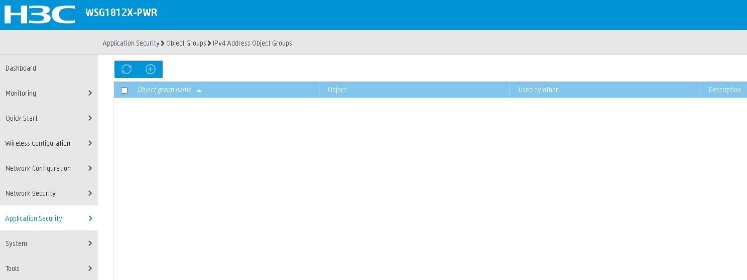
1. From the navigation pane, select Application Security > Object Groups > IPv4 Address Object Groups.
Figure 2 IPv4 address object group configuration page
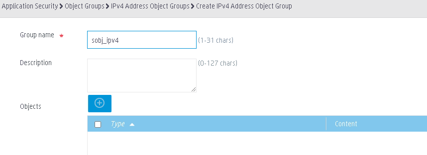
2. Click ![]() to add an IPv4 address object group named sobj_ipv4.
to add an IPv4 address object group named sobj_ipv4.
Figure 3 Configuring an object group name
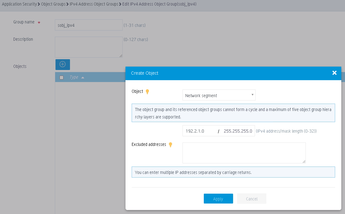
3. Click ![]() to
add an object for the object group:
to
add an object for the object group:
a. Select Network segment from the Object list.
b. Configure the network segment as 192.2.1.0/255.255.255.0.
c. Click Apply.
d. Click Apply to complete the configuration.
Figure 4 Adding an object
Configuring an anti-virus profile
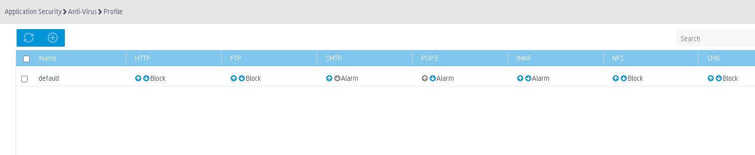
1. From the navigation pane, select Application Security > Anti-Virus > Profile.
Figure 5 Anti-virus profile configuration page
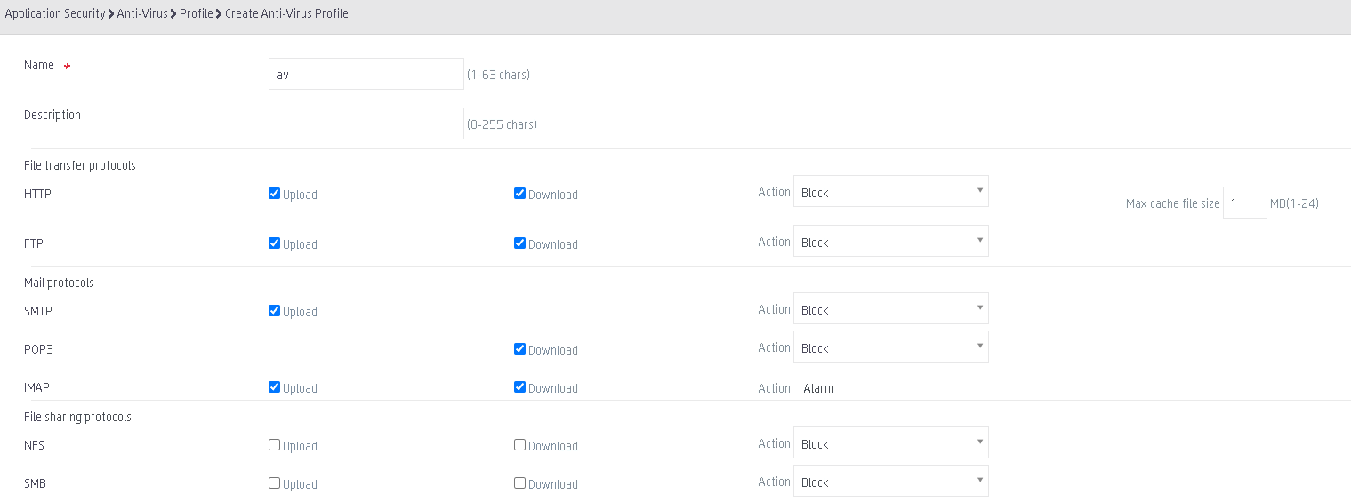
2. Click ![]() to add an anti-virus profile:
to add an anti-virus profile:
a. Enter av in the Name field.
b. In the File transfer protocols area, set the action to Block in both the upload and download directions for the HTTP and FTP protocols.
c. In the Mail protocols area, set the action to Block for the SMTP and POP3 mail protocols.
Figure 6 Adding an anti-virus profile
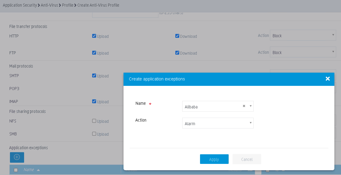
3. In the Application exceptions area, click ![]() to
add an application exception:
to
add an application exception:
a. Enter Alibaba in the Name field.
b. Set the action to Alarm.
c. Click Apply.
d. Click Apply to complete the configuration.
Figure 7 Adding an application exception
Configuring a security policy
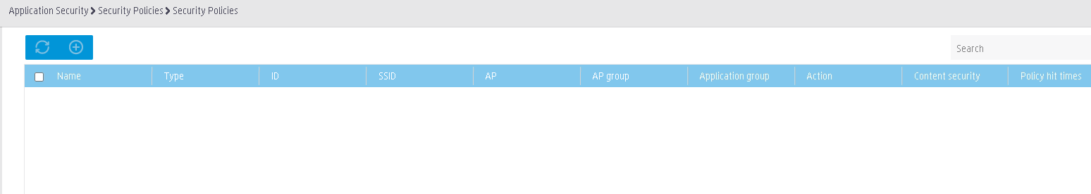
1. From the navigation pane, select Application Security > Security Policies > Security Policies.
Figure 8 Security policy configuration page
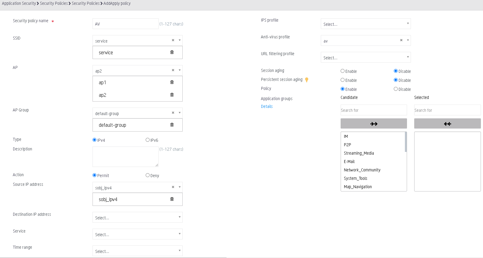
2. Click ![]() to add a security policy:
to add a security policy:
¡ Enter AV in the Security policy name field.
¡ Select SSID service.
¡ Select APs ap1 and ap2.
¡ Select AP group default-group.
¡ Select type IPv4.
¡ Set the action to Permit.
¡ Select source IP address sobj_ipv4.
¡ Select anti-virus profile av.
¡ Select Enable in the Policy field to enable the security policy.
¡ Click Apply.
Figure 9 Adding a security policy
Verifying the configuration
# Verify that the AC can use the anti-virus policy to detect and prevent viruses.
Related documentation
· H3C Access Controllers Web-Based Configuration Guide
