- Table of Contents
-
- 17-Network Management and Monitoring Configuration Guide
- 00-Preface
- 01-Information center configuration
- 02-Flow log configuration
- 03-Fast log output configuration
- 04-NetStream configuration
- 05-Sampler configuration
- 06-Cloud connection configuration
- 07-Mirroring configuration
- 08-Packet capture configuration
- 09-NQA configuration
- 10-Track configuration
- 11-BFD configuration
- 12-Monitor Link configuration
- 13-Smart Link configuration
- 14-Interface backup configuration
- 15-Interface collaboration configuration
- 16-System maintenance and debugging configuration
- 17-NTP configuration
- 18-EAA configuration
- 19-Process monitoring and maintenance configuration
- 20-NETCONF configuration
- 21-CWMP configuration
- 22-SNMP configuration
- 23-RMON configuration
- 24-Event MIB configuration
- 25-Process placement configuration
- 26-GOLD configuration
- 27-gRPC configuration
- 28-iNQA configuration
- 29-SmartMC configuration (self-mesh supported)
- Related Documents
-
| Title | Size | Download |
|---|---|---|
| 29-SmartMC configuration (self-mesh supported) | 801.07 KB |
Self-mesh SmartMC and non-self-mesh SmartMC
Configuring non-self-mesh SmartMC
Restrictions and guidelines: SmartMC configuration
Setting the FTP server information
Enabling automatic Ethernet link aggregation
Modifying the password for the default user for members
Deploying a batch file to members
Configuring a batch file for ports connecting APs or IP phones
Backing up configuration files
Configuring resource monitoring
Upgrading the startup software and configuration file on members
About upgrading the startup software and configuration file on members
Restrictions and guidelines for startup software and configuration file upgrade
Upgrading the startup software and configuration file on members
Upgrading the startup software and configuration file on all members in SmartMC groups
Refreshing the network topology
Display and maintenance commands for SmartMC
SmartMC configuration examples
Self-mesh SmartMC application scenarios
Basic concepts of self-mesh SmartMC
Role selection in self-mesh SmartMC
Self-mesh SmartMC network establishment and changing
SmartMC configuration management
QuickNet management platform login with a fixed domain name
Auto-switching of the DHCP server in SmartMC self-mesh networking
NTP in self-mesh SmartMC network
Restrictions and guidelines: Self-mesh SmartMC configuration
Self-mesh SmartMC tasks at a glance
Setting the network-wide SmartMC password
Setting the FTP server information
Display and maintenance commands for self-mesh SmartMC
Configuring SmartMC
About SmartMC
Smart Management Center (SmartMC) centrally manages and maintains dispersed network devices at network edges. In a SmartMC network, only one device acts as the commander and the remaining devices all act as members. SmartMC provides the following features for you to manage the members from the commander:
· Configuration file backup and download.
· Software upgrade.
· Configuration deployment.
· Faulty member replacement.
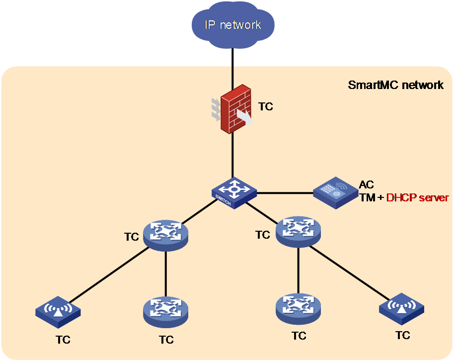
SmartMC network framework
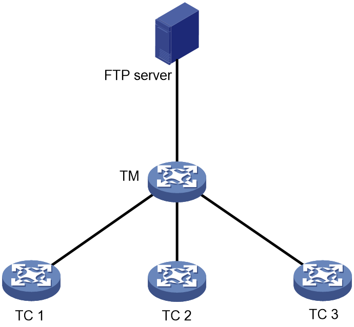
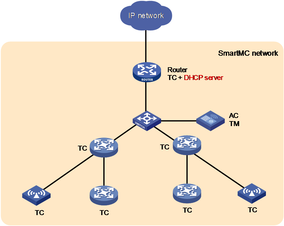
Figure 1 shows the basic framework of a SmartMC network.
The SmartMC network contains the following elements:
· Commander—Also called topology master (TM), which manages all members in the SmartMC network.
· Member—Also called topology client (TC), which is managed by the commander.
· FTP server—Stores startup software images and configuration files for the commander and members.
Figure 1 SmartMC network framework
Self-mesh SmartMC and non-self-mesh SmartMC
|
|
NOTE: The theory behind SmartMC self-mesh and non-self-mesh modes differ, so as the supported commands. Choose the appropriate mode based on device support and network scenarios. To switch the SmartMC mode, execute undo smartmc enable to disable SmartMC and restore the default SmartMC settings, and then use the smartmc enable command to configure SmartMC. |
SmartMC supports two operating modes: self-mesh and non-self-mesh, depending on the role selection method.
· Self-mesh mode: Automatically elects TM or TC roles in the network. If you execute smartmc enable, the system enables SmartMC and enters the self-mesh mode.
· Non-mesh mode: Allows users to manually configure TM or TC roles through the smartmc { tc | tm username username password { cipher | simple } string } enable command. If you execute this command, the system enables SmartMC and enters the non-mesh mode.
Table 1 Differences between self-mesh SmartMC and non-self-mesh SmartMC
|
Item |
Self-mesh SmartMC |
Non-self-mesh SmartMC |
|
Setup |
Use factory default settings to initialize configuration from the Web interface and set up a SmartMC network automatically. |
Require manual role (TM or TC) configuration |
|
Role election |
Auto |
Manual configuration |
|
Management method |
Use the SmartMC network management platform or the Cloudnet app |
Use the CLI, the SmartMC network management platform, or both |
|
Applicable network scenarios |
Unified wired and wireless access Currently, SmartMC self-mesh technology is applied to wireless QuickNet solutions. |
Wired networks |
|
Supported commands |
Only the smartmc enable, smartmc password, and smartmc ftp-server commands |
All SmartMC commands except the smartmc password command |
Configuring non-self-mesh SmartMC
|
|
NOTE: For simplicity purposes, the term "SmartMC" in this chapter refers to non-mesh SmartMC. For more information about self-mesh SmartMC, see "Configuring self-mesh SmartMC." |
About non-mesh SmartMC
Non-mesh SmartMC is a technology where network administrators manually configure devices as TM or TC in the SmartMC network using command lines and complete other relevant configurations before interconnecting them. The devices will join the SmartMC network according to the specified roles and complete the network formation. The TM manages TCs. It is the administrator's responsibility in a non-mesh SmartMC network to ensure that only one TM is present.
SmartMC network establishment
A SmartMC network can be established semi-automatically or manually.
· In a semi-automatically established SmartMC network, the commander obtains member information through NETCONF sessions to form the network topology. The member information includes port information, LLDP neighbor information, STP information, device type, and software version.
· In a manually established SmartMC network, the commander obtains member's LLDP neighbor information through NETCONF sessions and member's hardware information through SNMP Get operations.
Semi-automatic SmartMC network establishment
The commander and members use the following procedure to establish a SmartMC network semi-automatically:
1. After SmartMC is enabled, the commander broadcasts a SmartMC packet at 15-second intervals at Layer 2 to detect members in the network. The SmartMC packet contains information of the commander, such as its bridge MAC address and the IP address of VLAN-interface 1.
2. When a member receives the packet, it records the commander information, and returns a response packet to the commander. The response packet contains information of the member, such as its bridge MAC address and the IP address of VLAN-interface 1.
3. When the commander receives the response packet, it initiates a NETCONF session to the member with the default username admin and the default password admin. The commander then obtains detailed information about the member through the session, including port information, LLDP neighbor information, STP information, device type, and software version.
4. The commander establishes a connection to the member for tracking the liveliness of the member, and adds the member to the SmartMC network.
5. Based on the LLDP neighbor information obtained from all members, the commander forms a SmartMC topology.
After the SmartMC network is established, the commander and members check for the existence of each other by exchanging SmartMC packets.
· When a member receives a SmartMC broadcast packet from the commander, it compares the bridge MAC address in the packet with the recorded bridge MAC address. If the two bridge MAC addresses are the same, the member returns a response packet to the commander. If the member does not receive a broadcast packet from the commander within the limit time, the member determines that the commander does not exist in the network anymore. Then, the member clears the commander information. The limit time is a random value in the range of 60 to 120 seconds.
· When the commander receives a response packet from a member, it compares the bridge MAC address in the packet with the recorded bridge MAC address. If the two bridge MAC addresses are the same, the commander determines that the member still exists in the network. If the commander does not receive a response packet from a member within 150 seconds, the commander determines that the member is offline. Then, the commander sets the status of the member to offline.
Manual SmartMC network establishment
You can log in to the Web interface of the commander, and enter the IP address, username, and password of the members to manually add them to the network. The members can join the network without exchanging SmartMC packets with the commander. For more information, see Comware 7 Web-Based Products User Guide.
After you specify the information of a member on the commander, the commander performs the following operations to add the member to the network:
· Verify that the member can be accessed through Telnet.
· Obtain basic member information, including LLDP neighbor information through NETCONF.
· Obtain hardware information through SNMP Get operations.
SmartMC features
Bulk configuration deployment for members
This feature allows you to deploy multiple command lines to members from the commander, eliminating the need to log in to members and configure the command one by one.
The procedure for bulk configuration deployment is as follows:
1. The commander acts as a Telnet client and establishes Telnet connections to the members.
2. The commander deploys a batch file to the members through Telnet connections. The batch file is created on the commander and contains command lines to be deployed.
3. The members run the command lines in the file.
Bulk configuration deployment for ports connecting APs and IP phones
This feature allows the commander to automatically deploy specific configurations to a port connecting an AP or IP phone, simplifying access port configuration.
When the commander first detects the association of an AP or IP phone on a port through LLDP, it deploys the command lines in the specified batch file to the port. If no batch file is specified for the device type, the configurations on the port remain unchanged.
If the AP or IP phone disconnects from the port, the configurations on the port remain. When a new device comes online from the port, configurations used by the port depend on the new device type.
· If the new device is an AP or IP phone and has the same type as the disconnected device, the configurations on the port remain unchanged.
· If the new device is an AP or IP phone but has a different type as the disconnected device, the commander deploys the command lines in the specified batch file to the port. If no batch file is specified for the device type, the configurations on the port remain unchanged.
· If the new device is neither an AP nor an IP phone, the configurations on the port remain unchanged.
Configuration file backup
You can use the following methods to back up the next-startup configuration file on the commander and members:
· Automatic backup—Enable this feature for the commander and all members in the network to immediately perform a backup. After that, the commander and members back up the configuration file at a user-specified interval.
· Manual backup—Manually trigger a backup on the commander or the specified members or SmartMC groups.
To back up the configuration file on a member, the commander instructs the member by unicasting a SmartMC packet. When a member receives the packet, it saves the running configuration to the next-startup configuration file and uploads the file to the file server.
Startup software and configuration file upgrade
This feature enables users to upgrade startup software and the configuration file of member devices from the commander.
Before upgrade, you must upload the upgrade files from the commander to the FTP server and specify the upgrade files on the FTP server for the members to download.
The procedure for startup software and configuration file upgrade is as follows:
1. The commander instructs the members (or SmartMC group) to download the upgrade files from the FTP server.
2. The members download the upgrade files from the FTP server.
3. The members upgrade the startup software and configuration file as follows:
¡ Startup software upgrade—Performs an ISSU with the upgrade startup software files. The members might be restarted during the upgrade process.
¡ Configuration file upgrade—Replaces the current configuration file with the upgrade configuration file. The members will not be restarted during the upgrade process.
Faulty member replacement
You can use the following methods to replace a faulty member:
· Automatic replacement—Enables the commander to record the positions of all members in the topology for replacement. When the commander discovers that a new member has physically replaced the faulty member, it compares the new member with the faulty one. The commander performs a replacement if the following requirements are met:
¡ The new member is deployed at the same topological position as the faulty one.
¡ The models of the new member and faulty member are the same.
The commander then instructs the new member to download the configuration file of the faulty member from the FTP server. After downloading the configuration file, the new member runs the configuration file to complete the replacement.
· Manual replacement—After the faulty member is physically replaced, you manually trigger a configuration replacement. The new member will download the configuration file of the faulty member from the FTP server and run the file to complete the replacement.
Automatic link aggregation
Automatic link aggregation automatically bundles multiple physical Ethernet links between two members into one logical link, called an aggregate link. This feature provides increased link bandwidth and improved link reliability.
|
|
NOTE: · Automatic link aggregation cannot be performed between the commander and a member, or between a member and a device outside the SmartMC network. You can aggregate the links between the commander and a member manually. For more information about manual link aggregation, see Ethernet link aggregation in Layer 2—LAN Switching Configuration Guide. · Enabling or disabling automatic link aggregation might cause network flapping, and the members might go offline for a short period of time. |
VLAN creation for members
To simplify configuration and management, you can create a VLAN for members. Then, all access ports on a member that are not connected to other members or the commander are assigned to the VLAN.
If a member has access ports that are connected to offline devices, you must remove the offline devices before creating a VLAN for the member.
The VLAN creation fails for a member if one or more access ports cannot be assigned to the VLAN. If the VLAN creation fails, the VLAN memberships for the access ports are restored to the state before the VLAN was created.
The failure to create a VLAN for a member does not affect the VLAN creation for other members.
Resource monitoring
Resource monitoring allows you to view resource usage of commanders and members on the commander, such as CPU usage, memory usage, and temperature information.
Restrictions and guidelines: SmartMC configuration
SmartMC is supported only on the default MDC.
You need to enable SmartMC on both the commander and members and perform all the other tasks only on the commander.
The following features take effect only on members added to the SmartMC network automatically:
· Configuration file backup.
· Faulty member replacement.
· Startup software and configuration file upgrade.
· Automatic link aggregation.
Devices exchange SmartMC protocol packets, and set up and maintain the SmartMC network in VLAN 1. For the network to work correctly, make sure interfaces that connect member devices to each other allow packets in VLAN 1 to pass.
If a device is a PEX in an IRF 3 system, use the pex working-mode command to set the device operating mode to switch or auto before you add the device to the network. For more information about PEXs, see IRF in Virtual Technologies Configuration Guide.
SmartMC tasks at a glance
To configure SmartMC, perform the following tasks:
2. Setting the FTP server information
This task is required for configuring automatic configuration file backup, replacing faulty members, and upgrading the startup software and configuration file on members.
3. (Optional.) Enabling automatic Ethernet link aggregation
4. (Optional.) Modifying the password for the default user for members
This task is required for upgrading the startup software and configuration file on members and deploying a batch file to a SmartMC group.
6. (Optional.) Deploying and managing configuration
¡ Deploying a batch file to members
¡ Configuring a batch file for ports connecting APs or IP phones
¡ Backing up configuration files
7. (Optional.) Monitoring and maintaining the SmartMC network
¡ Configuring resource monitoring
¡ Upgrading the startup software and configuration file on members
¡ Managing the network topology
Prerequisites for SmartMC
Before you configure SmartMC, perform the following tasks on the commander and members:
· Enable the Telnet service, and configure scheme authentication for VTY user lines. For information about Telnet service and VTY user lines, see CLI login configuration in Fundamentals Configuration Guide.
· Configure a local user.
¡ Specify the username and password.
- On the commander, make sure the username and password are the same as the username and password configured by using the smartmc tm username username password { cipher | simple } string enable command.
- On a member, set both the username and password to admin, and execute the password-control length 4, password-control composition type-number 1 type-length 1, and undo password-control complexity user-name check commands to lower the password complexity requirements.
This is because SmartMC requires that the commander use username admin and password admin to communicate with members, which does not meet the default password complexity requirements. For more information about these commands, see password control commands in Security Command Reference.
After the SmartMC network is established, you can increase the password complexity requirements and use the smartmc tc password command to modify the username and password.
¡ Specify the Telnet, HTTP, and HTTPS services for the user.
¡ Set the RBAC role of the local user to network-admin.
For information about local users, see AAA configuration in Security Configuration Guide. For information about user roles, see RBAC configuration in Fundamentals Configuration Guide.
· Enable NETCONF over SOAP over HTTP. For information about NETCONF over SOAP, see NETCONF configuration in Network Management and Monitoring Configuration Guide.
· Enable LLDP globally. For information about LLDP, see Layer 2—LAN Switching Configuration Guide.
· To manage the commander and members through a Web interface, you must enable the HTTP and HTTPS services, and set the service type to HTTP and HTTPS for the local user. For information about Web login, HTTP, and HTTPS, see Fundamentals Configuration Guide.
· To manually establish a SmartMC network, you must configure the snmp-agent community read public and snmp-agent sys-info version v2c commands on the members. For information about SNMP, see Network Management and Monitoring Configuration Guide.
Enabling SmartMC
About this task
Enable this feature on both the commander and members to enable management of members from the commander.
Restrictions and guidelines
A SmartMC network must have one and only one commander.
If you change the role of the commander to member or disable SmartMC on the commander, all SmartMC settings in its running configuration will be cleared.
SmartMC fails to be enabled if ACL resources are insufficient. If ACL resources are insufficient, use the undo acl command to delete unnecessary ACLs and then enable SmartMC. You can execute the display acl command to view ACL configuration and match statistics. For more information about ACLs, see ACL and QoS Configuration Guide.
SmartMC fails to be enabled if ports 80 and 443 have been used.
Procedure
1. Enter system view.
system-view
2. Enable SmartMC and set the device role.
smartmc { tc | tm username username password { cipher | simple } string } enable
By default, SmartMC is disabled.
Setting the FTP server information
About this task
In a SmartMC network, an FTP server is used to store the following files:
· Upgrade startup software files and upgrade configuration file for members.
· Backup configuration files of the commander and members.
Restrictions and guidelines
You can use the following methods to specify an FTP server:
· Specify the IP address of an independent FTP server.
· Specify the IP address of the commander. The commander will act as an FTP server.
To configure the commander to act as an FTP server, make sure the commander has enough storage space for storing the files required by members. For information about FTP, see Fundamentals Configuration Guide.
To use an independent FTP server, connect the FTP server to the commander instead of the members as a best practice. The FTP server uses VLAN 1 to communicate with the SmartMC network. If you connect the FTP server to members, creating a VLAN for members will assign member interfaces connecting to the FTP server to the created VLAN, causing FTP server disconnection. For more information about member VLAN creation, see "Creating a VLAN for members."
Procedure
1. Enter system view.
system-view
2. Set the FTP server information.
smartmc ftp-server server-address username username password { cipher | simple } string
By default, no FTP server information is set.
Enabling automatic Ethernet link aggregation
Restrictions and guidelines
Enabling or disabling automatic Ethernet link aggregation might cause network flapping, and the members might go offline for a short period of time.
Procedure
1. Enter system view.
system-view
2. Enable automatic Ethernet link aggregation.
smartmc auto-link-aggregation enable
By default, automatic Ethernet link aggregation is disabled.
Modifying the password for the default user for members
About this task
During SmartMC network establishment, the commander uses the default username and password to establish NETCONF sessions to members automatically added to the network. The default username and password of the members for NETCONF session establishment are admin and admin.
To enhance security, you can perform this task to change the password for the default user admin of the members after the commander adds the members to the network.
Restrictions and guidelines
Do not modify the password for members that are manually added to the SmartMC network. If you modify the password for a manually added member, you will not be able to manage that member from the commander.
You can use the display smartmc tc verbose command to identify the method used to add the members.
Procedure
1. Enter system view.
system-view
2. Modify the password of the default user for members.
smartmc tc password [ cipher ] string
By default, the password of the default user is admin.
Creating a SmartMC group
About this task
This feature allows you to create a SmartMC group on the commander and add members to the group. When you perform the following operations, you can specify a SmartMC group to apply the operations to all members in the group:
· Startup software upgrade.
· Configuration file upgrade.
· Configuration deployment.
Procedure
1. Enter system view.
system-view
2. Create a SmartMC group and enter its view.
smartmc group group-name
3. (Optional.) Display predefined device types.
match device-type ?
4. Set a match criterion.
match { device-type device-type | ip-address ip-address { ip-mask-length | ip-mask } | mac-address mac-address mac-mask-length }
By default, no match criterion is set.
5. If the device type of the members is not predefined on the commander, perform the following tasks to manually define the device type on the commander:
a. Return to system view.
quit
b. Add a device type to the commander.
smartmc tc sysoid sysoid device-type device-type
To obtain the SYSOID of a member, execute the display smartmc tc verbose command.
You cannot define a predefined member type as another type.
Creating a VLAN for members
Restrictions and guidelines
If you perform this task multiple times to create a VLAN for members, the most recent configuration takes effect.
Procedure
1. Enter system view.
system-view
2. Creating a VLAN for members and assign access ports on the members to the VLAN.
smartmc vlan vlan-id { group group-name-list | tc tc-id-list }
Deploying a batch file to members
1. Execute the following command in user view to create a batch file and edit the command lines to be deployed to members.
create batch-file cmd-filename
Each command occupies a line in the batch file. When you finish editing, enter a percent sign (%) to return to user view.
Make sure the command lines that you enter are correct because the system does not verify whether the command lines are correct.
2. Enter system view.
system-view
3. Deploy the batch file to a list of members or SmartMC groups.
smartmc batch-file cmd-filename deploy { group group-name-list | tc tc-id-list }
Configuring a batch file for ports connecting APs or IP phones
Restrictions and guidelines
All commands in the batch file must be commands used in interface view.
The size of the batch file cannot exceed 8190 characters.
Make sure the file name is correct when specifying the batch file because the system does not verify whether the file name is correct. After specifying the batch file, do not delete the file or rename the file.
Procedure
1. (Optional.) Execute the following command in user view to create a batch file and edit the command lines to be deployed to members.
create batch-file cmd-filename
Each command occupies a line in the batch file. When you finish editing, enter a percent sign (%) to return to user view.
Make sure the command lines that you enter are correct because the system does not verify whether the command lines are correct.
2. Enter system view.
system-view
3. Specify the batch file for ports connecting APs or IP phones.
smartmc batch-file batch-file-name apply { ap | phone }
Backing up configuration files
About this task
Perform this task to back up the configuration file of the commander or the specified members. Configuration files automatically backed up to the FTP server are named in the format of device_bridge_MAC_address_backup.cfg.
Restrictions and guidelines
When you change the commander in the SmartMC network, make sure the backup configuration file of the original commander on the FTP server is deleted. If the file still exists, the new commander might download the file and run the settings. This will cause a conflict in the network.
The maximum number of members that can perform automatic configuration at the same time is limited by the performance of the FTP server. If automatic configuration backup fails, set the maximum number of members to a smaller value.
Prerequisites
Before performing this task, you must set the FTP server information (see "Setting the FTP server information").
Procedure
1. Enter system view.
system-view
2. Set the maximum number of members that can perform configuration file backup at the same time.
smartmc backup configuration max-number max-number
By default, a maximum of five members can perform automatic configuration backup at the same time.
3. Back up configuration files.
Choose one option as needed:
¡ Enable automatic configuration file backup and set the backup interval.
smartmc backup startup-configuration interval interval-time
By default, automatic configuration file backup is disabled.
¡ Manually back up the configuration file on the commander or the specified members.
smartmc backup configuration { group group-name-list | tc [ tc-id-list ] }
TC ID 0 represents the commander.
Configuring resource monitoring
4. Enter system view.
system-view
5. Set the interval for the commander to obtain resource monitoring information.
smartmc resource-monitor interval interval
The default setting is 1 minute.
6. Set the aging time for resource monitoring information.
smartmc resource-monitor max-age max-age
The default setting is 24 hours.
7. Enable resource monitoring.
smartmc resource-monitor [ cpu | memory | temperature ] * [ group group-name-list | tc { tc-id-list | mac-address mac-address } | tm ]
By default, resource monitoring is disabled.
If you do not specify a resource type, this command enables resource monitoring for all resource types.
If you do not specify a device to monitor (member or commander), this command enables resource monitoring on the commander and all members.
Upgrading the startup software and configuration file on members
About upgrading the startup software and configuration file on members
You can use the following methods to upgrade the startup software and configuration file on members:
· Schedule an upgrade by specifying an upgrade time or upgrade delay.
· Upgrade immediately by not specifying an upgrade time or upgrade delay.
Restrictions and guidelines for startup software and configuration file upgrade
A member can perform only one upgrade task at a time.
An immediate upgrade cannot be cancelled. If you specify a delay time or upgrade time to perform a scheduled upgrade, the upgrade operation can be cancelled by using the undo smartmc upgrade command before it starts.
Prerequisites
Before performing this task, you must set the FTP server information (see "Setting the FTP server information").
Upgrading the startup software and configuration file on members
Upgrading the startup software and configuration file in one step
1. Enter system view.
system-view
2. Upgrade the startup software on members in one step.
smartmc upgrade boot-loader tc { tc-id-list { boot boot-filename system system-filename | file ipe-filename } }&<1-40> [ delay delay-time | time in-time ]
|
|
CAUTION: Upgrading the startup software might interrupt services. Before upgrading the startup software, make sure service operation will not be affected. |
3. Upgrade the configuration file on members in one step.
smartmc upgrade startup-configuration tc { tc-id-list cfg-filename }&<1-40> [ delay delay-time | time in-time ]
|
|
CAUTION: After a file upgrade, the device runs with the configurations in the new file. For the device to operate correctly, make sure configurations in the new file are correct. |
Configuring startup software and configuration file upgrade step by step
1. Enter system view.
system-view
2. Configure startup software upgrade for members step by step:
a. Specify the upgrade startup software files.
smartmc tc tc-id boot-loader { ipe-filename | boot boot-filename system system-filename }
b. Upgrade the startup software on members.
smartmc upgrade boot-loader tc tc-id-list
|
|
CAUTION: Upgrading the startup software might interrupt services. Before upgrading the startup software, make sure service operation will not be affected. |
3. Configure configuration file upgrade for members step by step:
a. Specify the upgrade configuration file.
smartmc tc tc-id startup-configuration cfg-filename
b. Upgrade the configuration file on members.
smartmc upgrade startup-configuration tc tc-id-list
|
|
CAUTION: After a file upgrade, the device runs with the configurations in the new file. For the device to operate correctly, make sure configurations in the new file are correct. |
Upgrading the startup software and configuration file on all members in SmartMC groups
Upgrading the startup software and configuration file in one step
1. Enter system view.
system-view
2. Upgrade the startup software on all members in SmartMC groups in one step.
smartmc upgrade boot-loader group { group-name-list [ boot boot-filename system system-filename | file ipe-filename ] }&<1-40> [ delay minutes | time in-time ]
|
|
CAUTION: Upgrading the startup software might interrupt services. Before upgrading the startup software, make sure service operation will not be affected. |
3. Upgrade the configuration file on all members in SmartMC groups in one step.
smartmc upgrade startup-configuration group { group-name-list file cfg-filename }&<1-40> [ delay minutes | time in-time ]
|
|
CAUTION: After a file upgrade, the device runs with the configurations in the new file. For the device to operate correctly, make sure configurations in the new file are correct. |
Configuring startup software and configuration file upgrade step by step
1. Enter system view.
system-view
2. Enter SmartMC group view.
smartmc group group-name
3. Specify the upgrade startup software files for the SmartMC group.
boot-loader file { ipe-filename | boot boot-filename system system-filename }
By default, no upgrade startup software files are specified for a SmartMC group.
4. Specify the upgrade configuration file for the SmartMC group.
startup-configuration cfgfile
By default, no upgrade configuration file is specified for a SmartMC group.
5. Return to system view.
quit
6. Upgrade the startup software and configuration file on all members in the SmartMC group.
Choose one option as needed:
¡ Upgrade the startup software.
smartmc upgrade boot-loader group group-name-list [ delay minutes | time in-time ]
|
|
CAUTION: Upgrading the startup software might interrupt services. Before upgrading the startup software, make sure service operation will not be affected. |
¡ Upgrade the configuration file.
smartmc upgrade startup-configuration group group-name-list [ delay minutes | time in-time ]
|
|
CAUTION: After a file upgrade, the device runs with the configurations in the new file. For the device to operate correctly, make sure configurations in the new file are correct. |
Managing the network topology
Refreshing the network topology
About this task
You can use the following methods to refresh the network topology:
· Automatic topology refresh—Specify the refresh interval to allow the commander to refresh the network topology periodically.
· Manual topology refresh—Execute the smartmc topology-refresh command to manually refresh the network topology.
Restrictions and guidelines
The topology refresh time depends on the number of members in the network.
Procedure
Choose one option as needed:
· Manually refresh the network topology in any view.
smartmc topology-refresh
· Configure automatic network topology refresh.
a. Enter system view.
system-view
b. Set the automatic topology refresh interval.
smartmc topology-refresh interval interval
By default, the automatic topology refresh interval is 60 seconds.
Saving the network topology
About this task
This task allows you to save the current network topology to the topology.dba file in the flash memory. After the commander reboots, it uses the topology.dba file to restore the network topology.
Procedure
1. Enter system view.
system-view
2. Save the network topology.
smartmc topology-save
Replacing faulty members
Restrictions and guidelines
Make sure the new member for replacement and the faulty member have the same neighbor relationship, device model, and IRF member ID.
Make sure the new member has a different member ID than all the members in the SmartMC network, including offline members. Faulty members are considered offline.
To automatically replace a faulty member, first enable automatic replacement, and then install the new member at the location where the faulty member was installed and connect all cables.
To manually replace a faulty member, first install the new member at the location where the faulty member was installed, connect all cables, and then execute the manual replacement command.
Prerequisites
Before you replace a faulty member, set the FTP server information (see "Setting the FTP server information").
Procedure
1. Enter system view.
system-view
2. Replace faulty members.
Choose one option as needed:
¡ Enable automatic faulty member replacement.
smartmc auto-replace enable
By default, automatic faulty member replacement is disabled.
¡ Manually replace a faulty member.
smartmc replace tc tc-id1 faulty-tc tc-id2
Display and maintenance commands for SmartMC
Execute display commands in any view.
|
Task |
Command |
|
Display the backup status on members. |
display smartmc backup configuration status |
|
Display the batch file execution results. |
display smartmc batch-file status [ ap | last number | phone ] |
|
Display SmartMC configuration. |
display smartmc configuration |
|
Display connections between the devices in the SmartMC network. |
display smartmc device-link |
|
Display SmartMC group information. |
display smartmc group [ group-name ] [ verbose ] |
|
Display the faulty member replacement status. |
display smartmc replace status |
|
Display resource monitoring information. |
display smartmc resource-monitor [ cpu | memory | temperature ] * [ tc tc-id | tm ] |
|
Display resource monitoring configuration. |
display smartmc resource-monitor configuration |
|
Display member information. |
display smartmc tc [ tc-id ] [ verbose ] |
|
Display log information in the log buffer on a member. |
display smartmc tc tc-id log buffer [ module module-name [ mnemonic mnemonic-value ] ] |
|
Display restart log information for a member. |
display smartmc tc tc-id log restart |
|
Display VLAN creation results for members. |
display smartmc vlan |
|
Display member upgrade status. |
display smartmc upgrade status |
SmartMC configuration examples
Example: Configuring SmartMC
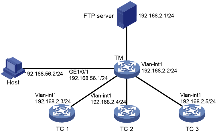
Network configuration
As shown in Figure 2, member 1, member 2, and member 3 belong to the same device type: S5560-EI series. The IP address of the FTP server is 192.168.2.1. The FTP username is admin and the FTP password is hello12345.
Perform the following tasks to establish a SmartMC network and upgrade the configuration file on the member:
1. Configure the commander and members to automatically establish a SmartMC network.
2. Configure interface GigabitEthernet 1/0/1 as the outgoing interface for the SmartMC network.
3. Create a SmartMC group and add the members to the group.
4. Upgrade the configuration file on all members in the SmartMC group.
5. Save configuration file startup.cfg on the FTP server.
Procedure
1. Configure TC 1:
# Configure VLAN-interface 1.
<TC1> system-view
[TC1] interface vlan-interface 1
[TC1-Vlan-interface1] ip address 192.168.2.3 24
[TC1-Vlan-interface1] quit
# Enable HTTP and HTTPS.
[TC1] ip http enable
[TC1] ip https enable
# Enable the Telnet service.
[TC1] telnet server enable
# Enable NETCONF over SOAP over HTTP.
[TC1] netconf soap http enable
# Enable LLDP globally.
[TC1] lldp global enable
# Create a user.
[TC1] local-user admin
# Lower password complexity requirements. For more information about these commands, see password control commands in Security Command Reference.
[TC1-luser-manage-admin] password-control length 4
[TC1-luser-manage-admin] password-control composition type-number 1 type-length 1
[TC1-luser-manage-admin] undo password-control complexity user-name check
# Set the username and password to admin, add the telnet, http, and https service types, and authorize the user to use the network-admin user role.
[TC1-luser-manage-admin] password simple admin
[TC1-luser-manage-admin] service-type telnet http https
[TC1-luser-manage-admin] authorization-attribute user-role network-admin
[TC1-luser-manage-admin] quit
# Set scheme authentication for VTY user lines 0 to 63.
[TC1] line vty 0 63
[TC1-line-vty0-63] authentication-mode scheme
[TC1-line-vty0-63] quit
# Enable SmartMC and set the device role to member.
[TC1] smartmc tc enable
2. Configure TC 2 and TC 3 in the same way TC 1 is configured. (Details not shown.)
3. Configure the TM:
# Configure GigabitEthernet 1/0/1.
<TM> system-view
[TM] interface gigabitethernet 1/0/1
[TM-GigabitEthernet1/0/1] port link-mode route
[TM-GigabitEthernet1/0/1] ip address 192.168.52.2 24
[TM-GigabitEthernet1/0/1] quit
# Configure VLAN-interface 1.
[TM] interface vlan-interface 1
[TM-Vlan-interface1] ip address 192.168.2.2 24
[TM-Vlan-interface1] quit
# Enable HTTP and HTTPS.
[TM] ip http enable
[TM] ip https enable
# Enable the Telnet service.
[TM] telnet server enable
# Enable NETCONF over SOAP over HTTP.
[TM] netconf soap http enable
# Enable LLDP globally.
[TM] lldp global enable
# Create a user. Set the username to admin and password to hello12345, add the telnet, http, and https service types, and authorize the user to use the network-admin user role.
[TM] local-user admin
[TM-luser-manage-admin] password simple hello12345
[TM-luser-manage-admin] service-type telnet http https
[TM-luser-manage-admin] authorization-attribute user-role network-admin
[TM-luser-manage-admin] quit
# Set scheme authentication for VTY user lines 0 to 63.
[TM] line vty 0 63
[TM-line-vty0-63] authentication-mode scheme
[TM-line-vty0-63] quit
# Enable SmartMC, set the device role to commander, and set the username to admin and the password (plaintext) to hello12345.
[TM] smartmc tm username admin password simple hello12345 enable
# Specify GigabitEthernet 1/0/1 as the outgoing interface.
[TM] interface gigabitethernet 1/0/1
[TM-GigabitEthernet1/0/1] smartmc outbound
[TM-GigabitEthernet1/0/1] quit
# Set the FTP server IP address, username, and plaintext password to 192.168.2.1, admin, and hello12345, respectively.
[TM] smartmc ftp-server 192.168.2.1 username admin password simple hello12345
# Create SmartMC group S1 and enter its view.
[TM] smartmc group S1
# Create an IP address match criterion to add all members in the specified network segment to SmartMC group S1.
[TM-smartmc-group-S1] match ip-address 192.168.2.0 24
# Specify the upgrade configuration file startup.cfg for SmartMC group S1.
[TM-smartmc-group-S1] startup-configuration startup.cfg
[TM-smartmc-group-S1] quit
# Upgrade the configuration file on all TCs in SmartMC group S1.
[TM] smartmc upgrade startup-configuration group S1 file startup.cfg
Verifying the configuration
# Display brief information about all members after the SmartMC network is established.
[TM] display smartmc tc
TCID DeviceType Sysname IpAddress MacAddress Status Version
1 MSR3600 TC1 192.168.2.3 201c-e7c3-0300 Normal COMWAREV700R001
2 MSR3600 TC2 192.168.2.4 201c-e7c3-0301 Normal COMWAREV700R001
3 MSR3600 TC3 192.168.2.5 201c-e7c3-0302 Normal COMWAREV700R001
# Display the configuration file upgrade status on the members.
[TM] display smartmc upgrade status
ID IpAddress MacAddress Status UpdateTime UpdateFile
1 192.168.2.3 201c-e7c3-0300 Finished Immediately startup.cfg
2 192.168.2.4 201c-e7c3-0301 Finished Immediately startup.cfg
3 192.168.2.5 201c-e7c3-0302 Finished Immediately startup.cfg
Configuring self-mesh SmartMC
About self-mesh SmartMC
Self-mesh SmartMC is a technology where devices automatically form a network. In a self-mesh SmartMC scenario, devices are enabled with SmartMC by default. Through automatic elections, the TM and TCs are determined. The TM manages TCs.
Currently, self-mesh SmartMC is suited for some unified wired/wireless networks and is applied to wireless QuickNet solutions.
Benefits of self-mesh SmartMC
Self-mesh SmartMC has the following advantages:
· Simplifies network setup by supporting device plug-and-play. By using factory default settings, self-mesh SmartMC initializes configurations from the Web interface and then allows devices to automatically form a SmartMC network.
· Simplifies network maintenance by enabling centralized management and maintenance of many network devices through simple web-based operations on the SmartMC network management platform. This effectively solves operational problems in small and medium-sized campus networks.
Self-mesh SmartMC application scenarios
Self-mesh SmartMC is typically used in unified wired/wireless networks, enabling plug-and-play of wired and wireless devices as well as deployment with zero configuration. The application scenarios of self-mesh SmartMC can be divided into two categories:
· Network in which the gateway does not support self-mesh SmartMC.
· Network in which the gateway supports self-mesh SmartMC.
Scenario one: Self-mesh SmartMC not supported by the gateway
As shown in Figure 4, the switch and APs support self-mesh SmartMC, but the gateway does not. The gateway can be an optical modem or router provided by the carrier, or a router purchased by the user.
In this network, the switch and APs automatically form a SmartMC network with one AP elected as the TM, and other devices as TCs. After successful SmartMC network formation, mobile clients can use the Web interface or the Cloudnet app to manage and maintain the switch and APs in a centralized way.
Figure 3 Self-mesh SmartMC not supported by the gateway

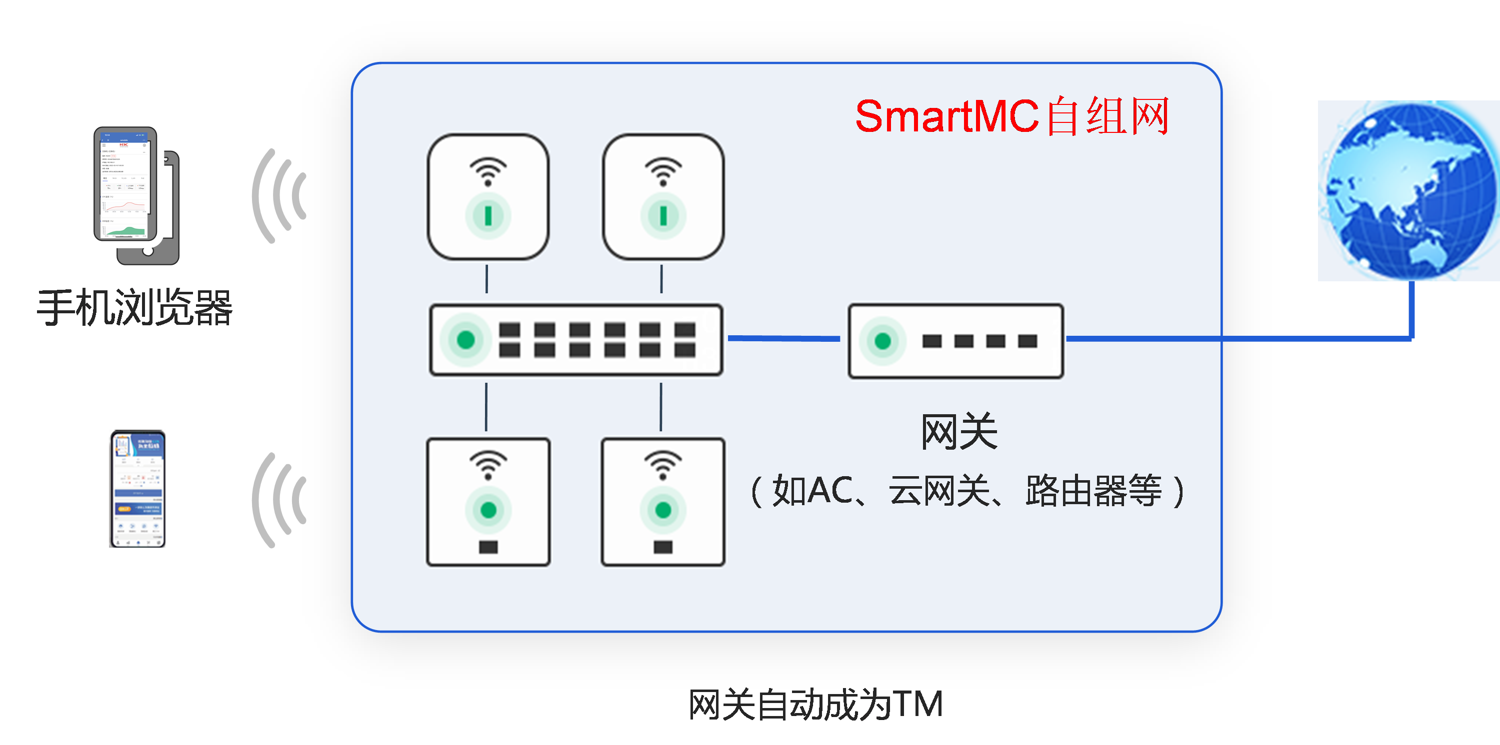
Scenario two: Self-mesh SmartMC supported by the gateway
As shown in Figure 4, all the devices, including the switch, APs, and gateway, support self-mesh SmartMC.
In this network, the switch, APs, and gateway automatically form a SmartMC network. Based on the SmartMC priorities in the default settings of the devices, the gateway is elected as the TM, and the other devices become TCs. After successful SmartMC network formation, centralized management and maintenance of the switch, APs, and gateway can be achieved through the SmartMC management platform.
Figure 4 Self-mesh SmartMC supported by the gateway
Basic concepts of self-mesh SmartMC
SmartMC device roles
In a self-mesh SmartMC network, devices support two roles:
· Topology master (TM): Manages all devices in the SmartMC network.
TM is automatically elected and displayed as TM(auto) in the output from a display command.
· Topology client (TC): Devices managed within the SmartMC network.
¡ Wireless devices, routers, security devices, and some switch models are automatically elected as TC(auto).
¡ Some switch models do not support self-mesh and are manually designated as TC, displayed as TC in the output from a display command.
|
|
CAUTION: · Some switch products are factory set as TC in self-mesh SmartMC networks, while others work in self-mesh mode. · To avoid disrupting SmartMC functionality, do not manually designate devices in self-mesh mode as TM or TC. · If such devices are manually configured as TM or TC, they will exit the self-mesh SmartMC mode and operate in non-self-mesh SmartMC mode. |
SmartMC network management platform (QuickNet management platform)
The SmartMC network management platform is a web-based interface provided by devices, allowing for centralized management and maintenance of numerous network devices. It effectively addresses operational issues in small to medium-sized networks.
In QuickNet solutions, the SmartMC network management platform is called the QuickNet management platform. Users can access the platform on a wireless endpoint connecting to the QuickNet Wi-Fi at quicknet.h3c.com or via the local management feature on the Cloudnet app.
In the configuring self-mesh SmartMC chapter, the term "QuickNet management platform" refers to the SmartMC network management platform.
SmartMC network-wide password
After establishing Layer 2 connections in the SmartMC network, the SmartMC module on the TM must establish Layer 3 communication channels with the NETCONF module on the TM and each TC to synchronize configurations and manage devices.
To ensure secure communication, a username and password are required for identity authentication between member devices during Layer 3 communication channel establishment. Devices are factory-set with default usernames and passwords. For both security and convenience purposes, SmartMC supports changing the Layer 3 communication channel password using the network-wide password function. When the TM changes the SmartMC network-wide password, it syncs with all member devices (including the TM and TCs), and all devices use the new password to establish new Layer 3 communication channels.
You can configure the SmartMC network-wide password from the CLI or the QuickNet management platform.
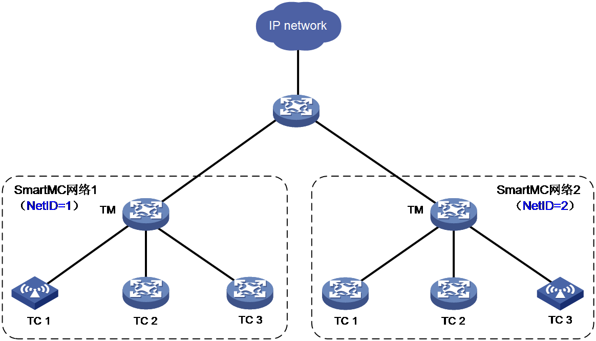
SmartMC NetID
NetID is the identifier of a SmartMC network in the SmartMC system, and one SmartMC network corresponds to only one NetID.
To adapt to various networking applications, multiple SmartMC networks can be deployed in the same network, and NetID is used to distinguish between different SmartMC networks. One device can only join one SmartMC network. As shown in Figure 5, the TM broadcasts SmartMC protocol packets to discover TCs in the respective SmartMC network. To avoid interference between SmartMC protocol packets of two SmartMC networks, SmartMC uses NetID to distinguish between different SmartMC networks. When a member device in a SmartMC network receives a SmartMC packet with a different NetID, it directly discards it.
NetID is automatically generated by the SmartMC software module when the network administrator configures the SmartMC network-wide password.
Figure 5 Multi-SmartMC network diagram
SmartMC startup deployment
When devices are first used to establish a SmartMC network, it is called SmartMC startup deployment. After device connection and startup, a Wi-Fi named H3C_QuickNet can be detected on wireless clients. By entering a fixed URL (quicknet.h3c.com) in the browser's address bar of the wireless client, the QuickNet management platform can be accessed. Clicking Start on the QuickNet management platform homepage starts the startup deployment process, and the TM will perform the following tasks:
· Generate a NetID for the current SmartMC network.
· Request the administrator logging in to set the management password (the SmartMC network-wide password), and synchronize the password and NetID to all member devices in the SmartMC network.
· Set the devices that have the network password and NetID to startup state. The startup state will affect the TM election process in the SmartMC network.
Role selection in self-mesh SmartMC
|
|
CAUTION: Devices manually set as TCs by using the smartmc tc enable command will not participate in role election, and devices manually set as TMs by using the smartmc tm enable command are not allowed to join the self-mesh SmartMC network. |
For devices that support self-mesh SmartMC, the role is not determined at the factory, and the TM is automatically elected through role election. The self-mesh SmartMC network conducts role election in the following situations:
· The devices are first interconnected, which triggers self-mesh SmartMC network formation.
· The TM leaves the network or malfunctions.
· The self-mesh SmartMC network splits.
· Two (or more) independent self-mesh SmartMC networks merge into one.
The following priority order is used to select the TM in the role election:
1. Devices with higher SmartMC election priority are selected first.
The priority of a device is carried by the factory parameters of the device, which is determined by the product according to the device model, the network location of the device, and other information. It cannot be modified by command line. For example, the priority of ACs is higher than that of switches and APs. If an AC, switches, and APs coexist in the network, AC will be selected as the TM first. The current SmartMC election priority of the device from high to low is: AC, router, security device, AP.
¡ If none of the devices participating in the role election have finished startup deployment, the device with higher SmartMC priority will be selected as the TM.
¡ If the SmartMC network has finished startup deployment and a new device with a higher priority than the TM joins, the new device synchronizes the global configuration of the current TM and runs as the TM. The new TM notifies the original TM to change to TC. If the SmartMC election priority of the new device is equal to or lower than that of the current TM, the role of the current TM remains unchanged, and the new device joins as a TC.
2. Devices in the startup state are given priority.
If the election priority is the same, and some devices have started while others have not, devices that have started will be selected as the TM first.
3. The TM in the SmartMC network with more member devices is given priority.
When two SmartMC networks merge, the two SmartMC networks compete for the TM. The SmartMC network with more member devices wins the election, and the TM in the winning SmartMC network becomes the TM for the entire merged SmartMC network. All member devices in the losing SmartMC network run as TC and synchronize the global configuration of the new TM.
4. Devices with higher health scores are given priority.
5. Devices with smaller bridge MAC addresses are given priority.
Devices running in self-mesh mode broadcast SmartMC election packets at Layer 2 and follow the above rules for judging from the first rule. If a rule matches multiple devices, the next rule will be used until a unique optimal member device is found. The unique optimal member device becomes the TM, and the other member devices become TCs.
Self-mesh SmartMC network establishment and changing
Self-mesh SmartMC network establishment
The process of establishing a self-mesh SmartMC network is as follows:
1. After a device starts up, it enters the automatic election process and broadcasts SmartMC election packets at intervals of 5 seconds. The packet includes the device's bridge MAC, NetID, SmartMC election priority, network size (number of member devices in the current SmartMC network), and the IP address of VLAN-interface 1.
2. After the automatic election, one TM is elected and other devices become TCs.
¡ If the device receives an election packet from other devices within 20 seconds, it compares its local parameters and the received SmartMC election packet according to the election rules. If the received packet is more optimal, the device switches to TC. If the device is more optimal, it continues to send SmartMC election packets to participate in the role election.
¡ If the device does not receive any election packets from other devices within 20 seconds, it switches to TM.
3. The TM broadcasts SmartMC discovery packets at intervals of 5 seconds to announce its TM identity.
4. Each TC records the device information of the TM and sends a SmartMC discovery ACK packet back to TM. At this time, you can use the display smartmc configuration command on the device to display the configured information of SmartMC.
5. The administrator uses a mobile terminal to search and connect to the Wi-Fi named H3C_QuickNet, visits quicknet.h3c.com, click Start on the login homepage. The QuickNet management platform automatically distributes LLDP, NETCONF, and local user configurations to member devices.
6. After receiving the TC's SmartMC discovery ACK packet, the TM uses the default username (admin) and password to establish a NETCONF connection with each member device, and obtains detailed information (such as port information, LLDP neighbor information, STP information, device type, and software version) through this connection. The default password for APs is h3capadmin, and the default password for other types of devices is admin.
7. A TC sends a SmartMC unicast login request packet to the TM. The packet includes the device's bridge MAC and the IP address of VLAN-interface 1.
8. After receiving the TC's login request packet, the TM replies with a login confirmation packet and adds the TC to the SmartMC network. At this point, the TC completes the online process. You can use the display smartmc tc command on the TM to view information about all TCs.
9. The TM forms the SmartMC network topology by using NETCONF connections to obtain its own and TCs' LLDP neighbor information. At this time, you can view the SmartMC network topology diagram on the QuickNet management platform, or use the display smartmc device-link command to display the connection information between devices in the SmartMC network.
10. The administrator selects the networking method, sets the administrator password (SmartMC network-wide password), and configures the Internet access parameters as instructed. Then, SmartMC network deployment is completed.
11. The TM synchronizes the network-wide password to itself and all TCs, and establishes a NETCONF connection with each devices using the default username and network-wide password.
New device joining
The mechanism for automatically electing TM when a new device joins is as follows:
1. After the SmartMC network is established, the TM broadcasts SmartMC discovery packets every 5 seconds, inquiring if there are member devices in the network.
2. When a new device is connected and powered on:
¡ If the device is a switch and has already been configured as a TC by the factory, it directly joins the SmartMC network as a TC.
¡ If the device is a non-switch device, the device's SmartMC function is enabled by default and it operates in self-mesh mode. The device enters the role election state and, according to the election rules, decides whether to run as TM or TC.
Member device leaving
After the SmartMC network is successfully established, the TM and TCs perceive each other's existence through SmartMC broadcast packets and response packets:
· After the TM leaves, a TC will enter the role election state if it fails to receive TM's SmartMC discovery packets within 20 seconds. TCs will then re-elect an TM according to the role election rules.
· After a TC leaves, the TM considers a TC as offline if it fails to receive any SmartMC discovery ACK packet from the TC within 20 seconds.
Self-mesh SmartMC splitting
If link failures occur between member devices in a self-mesh SmartMC network, TCs and TM may fail to reach each other, causing the SmartMC network to split into multiple SmartMC networks. After the splitting, one SmartMC network contains the original TM, while other SmartMC networks do not have a TM.
During the splitting, the SmartMC software module handles the situation as follows:
· For the SmartMC network that contains the original TM, the SmartMC network continues to operate normally, and the departing member devices become offline.
· For the other SmartMC networks, if some devices work in self-mesh mode, they consider the TM as faulty and trigger role election after 20 seconds without receiving any SmartMC broadcast discovery packets from the TM.
As shown in Figure 6, the roles of TM, TC 1, and TC 3 in the self-mesh SmartMC network are generated through election, and the role of TC 2 is manually specified. Assuming that this self-mesh SmartMC network has been established with a NetID of 1, the following scenarios might occur:
· When the link fails between TC 2 and the TM, TC 2 leaves the self-mesh SmartMC network, but its role remains as TC and its NetID remains as 1.
· When the link fails between TC3 and the TM, TC 3 leaves the self-mesh SmartMC network. After 20 seconds without receiving any SmartMC broadcast discovery packets from the TM, TC 3 re-elects itself as TM with a NetID of 1.
Figure 6 Self-mesh SmartMC splitting
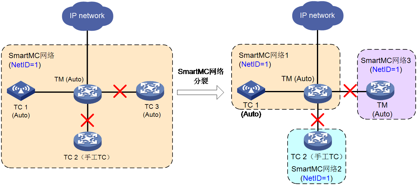
Self-mesh SmartMC merging
The process of multiple stable SmartMC networks interconnecting to form a self-mesh SmartMC network is called self-mesh SmartMC merging.
The following rules are followed during the self-mesh SmartMC merging:
· For SmartMC networks that have already been established, only SmartMC networks with the same NetID can be merged. SmartMC networks with different NetIDs cannot be merged.
· Established SmartMC networks can be merged with non-established SmartMC networks.
· When merging, the two SmartMC networks will compete for the TM role. For more information about the TM election rules, see "Role selection in self-mesh SmartMC."
As shown in Figure 7, three SmartMC networks exist in the current network. SmartMC network 1 and SmartMC network 3 have the same NetID, and SmartMC network 2 has a different NetID. When the link failure is recovered, the SmartMC networks will try to merge, as follows:
· SmartMC network 1 has two member devices, which is greater than the number of member devices in SmartMC network 2. Therefore, SmartMC network 1 wins the election and its TM will become the TM of the merged SmartMC network.
· The NetID of SmartMC network 2 is different from that of the other SmartMC networks, so it cannot be merged with any of the other SmartMC networks.
Figure 7 Self-mesh SmartMC merging
SmartMC configuration management
After member devices use Layer 2 connections to build the SmartMC network, the TM automatically establishes a NETCONF session with each TC using VLAN-interface 1. The TM uses the NETCONF sessions to distribute configurations to the TCs and obtain the values of some parameters on the TCs in order to manage and maintain the SmartMC network.
SmartMC supports the following configuration methods:
· Global configuration
Administrators can configure settings on the QuickNet management platform's web page or from the TM's CLI. These configurations are distributed to and take effect on all member devices. Global synchronized configurations include wireless, VLAN, gateway, SmartMC network-wide password, and FTP server settings.
· Batch configuration
Administrators can configure multiple devices by selecting them on the QuickNet management platform's web page. These configurations are distributed to and take effect on the selected member devices. Batch synchronization operations include batch reboot and factory reset.
· Single device configuration
In addition to SmartMC global configuration and batch configuration, administrators can configure parameters for a single member device in the following methods:
¡ Configure the settings for the specified device on the web page. These configurations will be distributed to and take effect on that device.
¡ For configurations not supported by the web page, such as disabling/enabling interfaces or adding interfaces to VLANs, administrators must log in to the member device and use the CLI to configure the settings.
QuickNet management platform login with a fixed domain name
In a self-mesh SmartMC network, use the QuickNet management platform for managing and configuring the network as a best practice. The platform is a web-based interface provided by the devices, allowing for easy management and maintenance of numerous network devices, addressing operational issues in small and medium-sized networks.
Typically, accessing the device's web interface requires its IP address or domain name. If you use a domain name, a DNS server must be deployed in the network and the domain-to-IP mapping must be configured. To simplify network deployment and user operations, SmartMC supports accessing the QuickNet management platform using fixed domain name quicknet.h3c.com, even without a DNS server.
The TM automatically establishes a mapping between quicknet.h3c.com and the IP address of the TM's VLAN-interface 1 and synchronizes it with all member devices. Users can log into the QuickNet management platform by connecting to any member device and entering the domain name quicknet.h3c.com.
Auto-switching of the DHCP server in SmartMC self-mesh networking
The auto-switching function of the DHCP server refers to the device automatically enabling or disabling its own DHCP server function based on networking needs:
· If the device detects an existing DHCP server in the current network, it automatically disables its own DHCP server function.
· If the device does not detect a DHCP server in the current network, it automatically enables its own DHCP server function.
Both AC and firewall devices support the DHCP server auto-switching function. When both AC and firewall are present in the network, only the DHCP server auto-switching function on the TM is active, and the auto-switching and DHCP server functions are disabled on TCs. The auto-switching function ensures that only one DHCP server exists in the self-mesh SmartMC network at any given time.
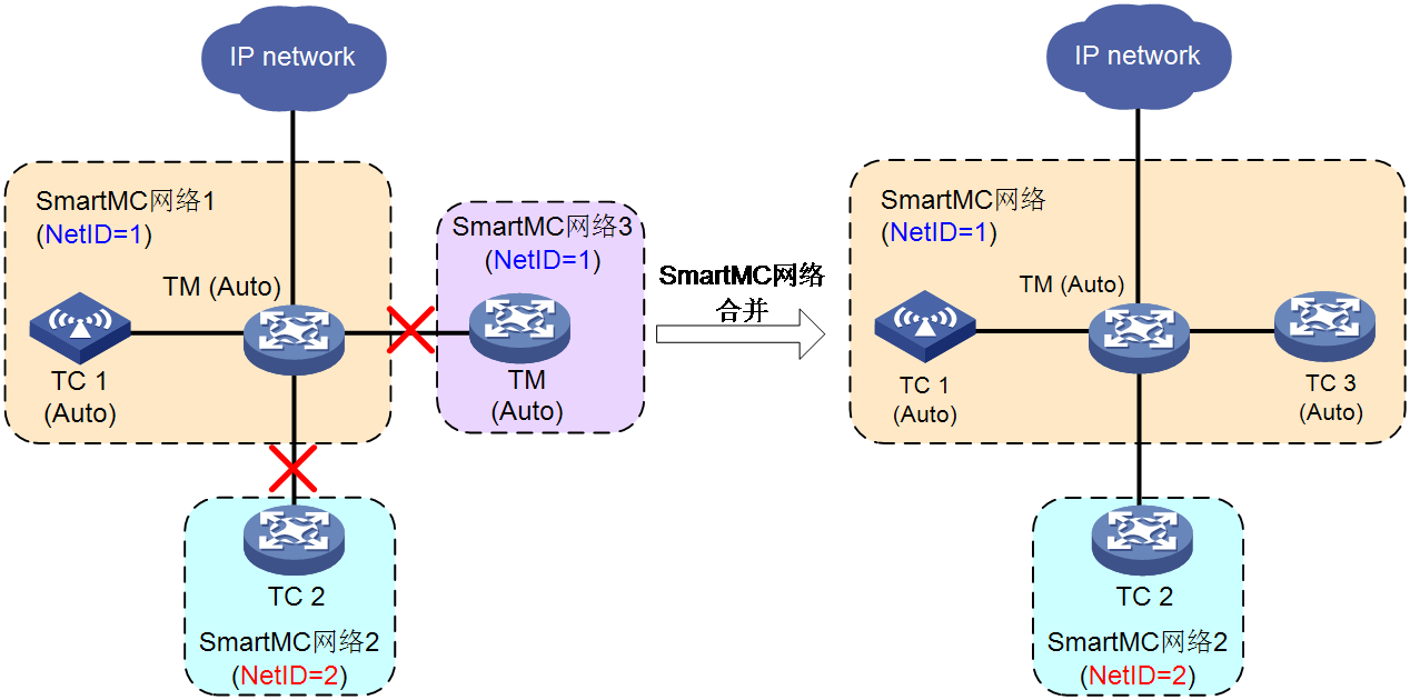
To support the self-mesh SmartMC function, the DHCP server function is enabled on VLAN-interface 1 on H3C AC, firewall, and router devices by default. This setup allows VLAN interface 1 to assign IP addresses to VLAN-interface 1 of the connected switches and APs when only AC, firewall, or router devices are present in the network. This enables these devices to automatically form a SmartMC network using factory settings, as shown in Figure 8.
Figure 8 Using the AC as the DHCP server when no firewall or router exists in the network
However, when the network contains two or more types of devices (ACs, firewalls, and routers), multiple DHCP servers might be present, which might cause IP address conflicts and prevent the devices from automatically form a SmartMC network. To ensure that only one DHCP server is operational at any given time in the self-mesh SmartMC network, SmartMC stipulates:
· For an operational self-mesh SmartMC network, the gateway specified at the start acts as the DHCP server. The DHCP server function must be disabled on the AC and firewall devices in the network and the auto-switching function of the DHCP server must also be disabled.
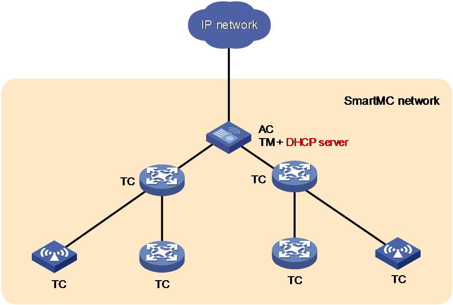
· For an undeployed self-mesh network:
¡ If a router is deployed (only one router is allowed) and the router acts as the DHCP server, the router does not support auto-switching of the DHCP server.
Figure 9 Using the router as the DHCP server
¡ The AC and firewall devices acting as TCs must be disabled with the DHCP server function and the auto-switching function of the DHCP server.
¡ The AC or firewall device acting as the TM must be enabled with the auto-switching function of the DHCP server. The TM will continuously detect if a DHCP server exists in the network.
- If a DHCP server is detected, the TM disables the DHCP server function.
- If no DHCP server is detected, the TM enables the DHCP server function and resets the IP addresses of VLAN-interface 1 on all TCs. The TCs re-obtain IP addresses for VLAN-interface 1 assigned by the new DHCP server.
This ensures that only one operating DHCP server exists in the network before the SmartMC network is deployed.
Figure 10 Using the TM as the DHCP server when no router exists in the network
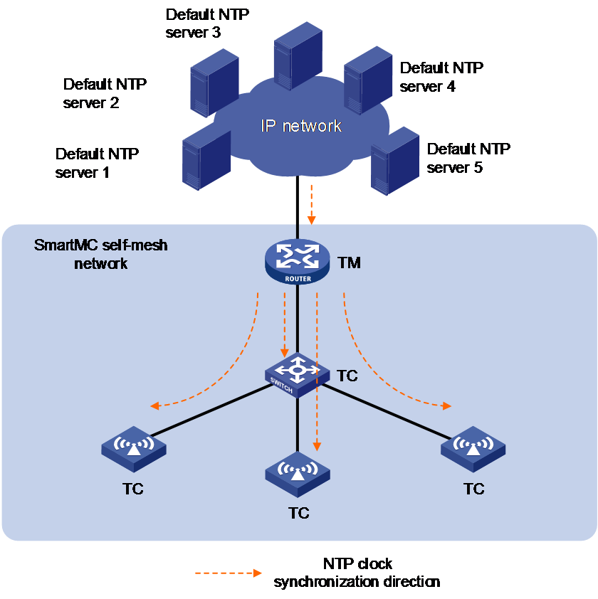
NTP in self-mesh SmartMC network
After the SmartMC network is deployed, the TM synchronizes time with all TCs through NTP. NTP provides millisecond-level time synchronization accuracy, meeting the general communication timing requirements of computer networks. For more information about NTP, see Network Management and Monitoring Configuration Guide.
The SmartMC network synchronizes the time as follows:
1. When the SmartMC network is deployed, the TM automatically deletes the existing NTP configuration on the device, and generates the NTP configuration dedicated for the SmartMC network.
2. The TM acts as the NTP client to synchronize the time from the external NTP server.
By default, the device supports five external NTP servers. When the device receives clock signals from multiple default NTP servers, it selects the best clock signal for synchronization. The addresses of the five clock servers are:
¡ registry.h3c.com (H3C time server)
¡ s2f.time.edu.cn (northeast regional network center)
¡ cn.pool.ntp.org (domestic time server for the NTP project)
¡ 1.cn.pool.ntp.org (domestic time server for the NTP project)
¡ asia.pool.ntp.cn (Asian time server for the NTP project)
3. If all the five NTP servers in the external network are unavailable, the TM changes the level of the local clock to 6 and uses the local clock as the clock source for the SmartMC network.
4. The TM acts as the NTP server and the TCs act as the NTP clients to perform time synchronization.
Figure 11 NTP time synchronization in the SmartMC network
Restrictions and guidelines: Self-mesh SmartMC configuration
SmartMC is supported only on the default MDC.
The device is initially started with factory settings. After administrators initialize the devices on the QuickNet management platform at quicknet.h3c.com, the devices can automatically form a SmartMC network.
Device exchange SmartMC protocol packets and establish/maintain the SmartMC network within VLAN 1. To ensure normal operation of SmartMC, make sure that VLAN 1 packets are allowed to pass through interfaces that connect member devices to each other.
Self-mesh SmartMC tasks at a glance
To configure self-mesh SmartMC, perform the following tasks:
6. Setting the network-wide SmartMC password
For security purposes, set the network-wide SmartMC password as a best practice.
7. (Optional.) Setting the FTP server information
Enabling SmartMC
Restrictions and guidelines
In a self-mesh SmartMC network, avoid manually assigning roles of TM or TC to devices. Doing so will start the non-SmartMC mode, preventing joining into the SmartMC network.
Make sure only one management device exists in a SmartMC network.
SmartMC requires some ACL resources. Insufficient resources can result in enabling failure of SmartMC. You can use the display acl command to view ACL configuration and running status, and use the undo acl command to delete unused ACLs to release resources. For more information about ACLs, see the ACL and QoS Configuration Guide.
When you enable SmartMC, the device examines if ports 80 and 443 are in use. If they are occupied, SmartMC cannot be enabled because HTTP and HTTPS services require the ports.
When you switch the management device to a member device or disable SmartMC, the system clears SmartMC-related settings in the running configuration.
Procedure
1. Enter system view.
system-view
2. Enable SmartMC.
smartmc enable
By default, SmartMC is disabled.
Setting the network-wide SmartMC password
About this task
To manage and maintain a SmartMC network, the TM establishes a NETCONF channel with each TC by using the local username (admin) and the default password. To increase device security, you can perform this task to change the password used for NETCONF channel establishment. With the network-wide password set on the TM, the TM issues the password to all member devices. The TM and TCs use the password to re-establish NETCONF channels.
Procedure
1. Enter system view.
system-view
2. Set the network-wide SmartMC password.
smartmc password [ cipher ] string
By default, the default password is h3capadmin for APs and admin for devices of other types.
Setting the FTP server information
About this task
In a SmartMC network, an FTP server is used to store the following files:
· Upgrade startup software files and upgrade configuration file for members.
· Backup configuration files of the commander and members.
After you configure FTP server information on the TM, the TM deploys the information to all member devices. This ensures that the FTP configuration remains active when another device takes up the TM role.
Restrictions and guidelines
You can use the following methods to specify an FTP server:
· Use the TM as the FTP server. Make sure the TM has sufficient space to save files required by TCs. For more information about FTP servers, see Fundamentals Configuration Guide.
· Use an independent FTP server. To use an independent FTP server, connect the FTP server to the TM as a best practice. The FTP server uses VLAN 1 to communicate with the SmartMC network. If you connect the FTP server to TCs, creating a VLAN for members will assign member interfaces connecting to the FTP server to the created VLAN, causing FTP server disconnection.
Procedure
1. Enter system view.
system-view
2. Configure FTP server information.
smartmc ftp-server server-address username username password { cipher | simple } string
By default, no FTP server is specified.
Display and maintenance commands for self-mesh SmartMC
Execute display commands in any view.
|
Task |
Command |
|
Display SmartMC configuration. |
display smartmc configuration |
|
Display member device information. |
display smartmc tc [ tc-id ] [ verbose ] |
|
Display information about inter-device connections in the SmartMC network. |
display smartmc device-link |