- Table of Contents
- Related Documents
-
| Title | Size | Download |
|---|---|---|
| 02-NAT66 configuration | 134.01 KB |
Contents
IPv6 source prefix translation
IPv6 destination prefix translation
NAT66 support for hot backup in collaboration with virtual IP addresses
Configuring IPv6 source prefix translation
Configuring IPv6 destination prefix translation
Display and maintenance commands for NAT66
Example: Configuring IPv6 source prefix translation (single internal and external network)
Example: Configuring IPv6 source prefix translation (multihomed network)
Example: Configuring IPv6 destination prefix translation
Configuring NAT66
Overview
IPv6-to-IPv6 Network Prefix Translation (NPTv6), also known as NAT66, translates the internal IPv6 prefix in the IPv6 packet header to an external IPv6 prefix and vice versa. A device that implements NAT66 translation is called a NAT66 device.
IPv6 source prefix translation
NAT66 source address translation is applicable to the following scenarios:
· Single internal and external network—The NAT66 device is connected to an internal network and an external network. Hosts in the internal network uses locally routed IPv6 prefixes. When an internal host sends packets to access the external network, the NAT66 device translates the source IPv6 address prefix in the packets to a global unicast address prefix.
· Redundancy and load sharing—Multiple NAT66 devices are deployed between two IPv6 networks and they use ECMPs for load sharing. To allow any NAT66 device to process IPv6 traffic among different sites, configure the same source prefix mappings on these NAT66 devices.
· Multihoming—In a multihomed network, NAT66 devices are connected to an internal network and multiple external networks. One internal prefix is mapped to different external prefixes on the NAT66 devices, so that one internal address can be translated to multiple external addresses.
IPv6 destination prefix translation
To allow external users to access internal servers, such as Wed server or FTP server, configure IPv6 destination prefix mappings on the interface connected to the external network.
NAT66 ALG
NAT66 ALG (Application Level Gateway) translates address or port information in the application layer payloads to ensure connection establishment.
For example, an FTP application includes a data connection and a control connection. The IP address and port number for the data connection depend on the payload information of the control connection. This requires NAT66 ALG to translate the address and port information for data connection establishment.
NAT66 ALG supports the following protocol packets: FTP packets and ICMP error messages.
NAT66 support for hot backup in collaboration with virtual IP addresses
You configure NAT66 on a hot backup system in collaboration with virtual IP addresses (also known as floating addresses). After NAT66, both the hot backup active and standby devices advertise the mappings between the IPv6 addresses after translation and MAC addresses of their own physical interfaces to all nodes in the same LAN. As a result, the upstream Layer 3 device directly connected to the hot backup system might incorrectly send downlink packets to the hot backup standby device, causing service anomalies.
To avoid such an issue, configure only the hot backup active device to advertise the mappings between the IPv6 addresses after translation and virtual MAC address corresponding to the virtual IP address.
Upon receiving an ARP reply from the hot backup active device, the upstream Layer 3 device updates the IP-MAC mapping. Then, it encapsulates downlink packets in which the destination IP address is a translated IP address with the virtual MAC address. The device sends the packets to the hot backup active device to ensure normal services.
Configuring IPv6 source prefix translation
Restrictions and guidelines
On one interface, the mapping between an internal prefix and an external prefix must be unique.
On different interfaces, different internal prefixes cannot be mapped to the same external prefix.
When you configure source address translation in NO-PAT mode, specify the same IPv6 prefix length before and after NAT66 in a mapping.
The source IPv6 prefix after translation cannot be the same as the external prefix of the NAT66 device or the prefix of the external destination address.
You can configure the global NAT policy to achieve IPv6 source prefix translation. For more information about global NAT policy,see "Configuring NAT."
This feature cannot perform translation on AH or ESP packets.
Procedure
1. Enter system view.
system-view
2. Enter interface view.
interface interface-type interface-number
3. Configure an IPv6 prefix mapping for IPv6 source address translation.
nat66 prefix source original-ipv6-prefix prefix-length [ vpn-instance original-vpn-instance-name ] translated-ipv6-prefix prefix-length [ vpn-instance translated-vpn-instance-name ] [ pat ]
By default, no IPv6 prefix mappings are configured for IPv6 source address translation.
Configuring IPv6 destination prefix translation
Restrictions and guidelines
On one interface, the mapping between an external prefix and an internal prefix must be unique.
On different interfaces, one external prefix cannot be mapped to different internal prefixes.
The external IPv6 prefix of the internal server cannot be the same as the external prefix of the NAT66 device or the prefix of external hosts that access the internal server.
You can configure the global NAT policy to achieve IPv6 destination prefix translation. For more information about global NAT policy, see "Configuring NAT."
This feature cannot perform translation on AH or ESP packets.
Procedure
1. Enter system view.
system-view
2. Enter interface view.
interface interface-type interface-number
3. Configure an IPv6 prefix mapping for IPv6 destination address translation.
nat66 prefix destination [ protocol pro-type ] original-ipv6-prefix prefix-length [ global-port ] [ vpn-instance original-vpn-instance-name ] translated-ipv6-prefix prefix-length [ local-port ] [ vpn-instance translated-vpn-instance-name ]
By default, no IPv6 prefix mappings are configured for IPv6 destination address translation.
Display and maintenance commands for NAT66
Execute display commands in any view and reset commands in user view.
|
Task |
Command |
|
Display all NAT66 configurations. |
display nat66 all |
|
Display NAT66 sessions. |
display nat66 session [ [ responder ] { source-ip source-ip-start [ source-ip-end ] | destination-ip destination-ip-start [ destination-ip-end ] | source-port source-port | destination-port destination-port | protocol { dccp | icmpv6 | raw-ip | sctp | tcp | udp | udp-lite } | application application-name | state { dccp-closereq | dccp-closing | dccp-open | dccp-partopen | dccp-request | dccp-respond | dccp-timewait | icmpv6-reply | icmpv6-request | rawip-open | rawip-ready | sctp-closed | sctp-cookie-echoed | sctp-cookie-wait | sctp-established | sctp-shutdown-ack-sent | sctp-shutdown-recd | sctp-shutdown-sent | tcp-close | tcp-close-wait | tcp-est | tcp-fin-wait | tcp-last-ack | tcp-syn-recv | tcp-syn-sent | tcp-syn-sent2 | tcp-time-wait | udp-open | udp-ready | udplite-open | udplite-ready } | interface { interface-name | interface-type interface-number } } * [ vpn-instance vpn-instance-name ] [ slot slot-number ] [ verbose ] |
|
Display NAT66 statistics. |
display nat66 statistics [ summary ] [ slot slot-number ] |
|
Delete NAT66 sessions. |
reset nat66 session [ slot slot-number ] |
NAT configuration examples
Example: Configuring IPv6 source prefix translation (single internal and external network)
Network configuration
As shown in Figure 1, internal users use IPv6 prefix FD01:0203:0405::/48 and the internal IPv6 addresses are not routable on the Internet. For internal users to access the FTP server on the Internet, configure IPv6 source prefix translation to translate the internal IPv6 prefix FD01:0203:0405::/48 to external prefix 2001:0DF8:0001::/48.

Procedure
1. Assign IPv6 addresses to interfaces:
# Assign an IPv6 address to interface GigabitEthernet 1/0/1.
<Device> system-view
[Device] interface gigabitethernet 1/0/1
[Device-GigabitEthernet1/0/1] ipv6 address FD01:0203:0405::10 48
[Device-GigabitEthernet1/0/1] quit
# Assign IPv6 addresses to other interfaces in the same way. (Details not shown.)
2. Configure settings for routing.
This example configures a static route, and the next hop in the route is 2001:0DB8:0001::11.
[Device] ipv6 route-static 2001:0DC8:0001::100 48 2001:0DB8:0001::11
3. Add interfaces to security zones.
[Device] security-zone name trust
[Device-security-zone-Trust] import interface gigabitethernet 1/0/1
[Device-security-zone-Trust] quit
[Device] security-zone name untrust
[Device-security-zone-Untrust] import interface gigabitethernet 1/0/2
[Device-security-zone-Untrust] quit
4. Configure a security policy:
# Configure a rule named trust-untrust to permit the packets from Host A and Host B to the FTP server.
[Device] security-policy ipv6
[Device-security-policy-ipv6] rule 1 name trust-untrust
[Device-security-policy-ipv6-1-trust-untrust] source-zone trust
[Device-security-policy-ipv6-1-trust-untrust] destination-zone untrust
[Device-security-policy-ipv6-1-trust-untrust] source-ip-host FD01:0203:0405::1
[Device-security-policy-ipv6-1-trust-untrust] source-ip-host FD01:0203:0405::2
[Device-security-policy-ipv6-1-trust-untrust] destination-ip-host 2001:0DC8:0001::100
[Device-security-policy-ipv6-1-trust-untrust] action pass
[Device-security-policy-ipv6-1-trust-untrust] quit
[Device-security-policy-ipv6] quit
5. Configure IPv6 source prefix translation:
# Configure an IPv6 source prefix mapping from FD01:0203:0405::/48 to FD01:0203:0405::/48.
[Device] interface gigabitethernet 1/0/2
[Device-GigabitEthernet1/0/2] nat66 prefix source fd01:0203:0405:: 48 2001:0df8:0001:: 48
[Device-GigabitEthernet1/0/2] quit
Verifying the configuration
# Verify that internal hosts can access the FTP server. (Details not shown.)
# Verify NAT66 configurations.
[Device] display nat66 all
NAT66 source information:
Totally 1 source rules.
Interface(outbound): GigabitEthernet1/0/2
Original prefix/prefix-length: FD01:203:405::/48
Translated prefix/prefix-length: 2001:DF8:1::/48
# Verify that NAT66 sessions are established.
<Device> display nat66 session verbose
Slot 1:
Initiator:
Source IP/port: FD01:203:405::1/56002
Destination IP/port: 2001:DC8:1::100/21
VPN instance/VLAN ID/Inline ID: -/-/-
Protocol: TCP(6)
Inbound interface: GigabitEthernet1/0/1
Source security zone: Trust
Responder:
Source IP/port: 2001:DC8:1::100/21
Destination IP/port: 2001:DF8:1:D50F::1/56002
VPN instance/VLAN ID/Inline ID: -/-/-
Protocol: TCP(6)
Inbound interface: GigabitEthernet1/0/2
Source security zone: Untrust
State: TCP_ESTABLISHED
Application: FTP
Rule ID: 1
Rule name: 1
Start time: 2018-12-06 14:48:31 TTL: 3597s
Initiator->Responder: 0 packets 0 bytes
Responder->Initiator: 0 packets 0 bytes
Total sessions found: 1
Example: Configuring IPv6 source prefix translation (multihomed network)
Network configuration
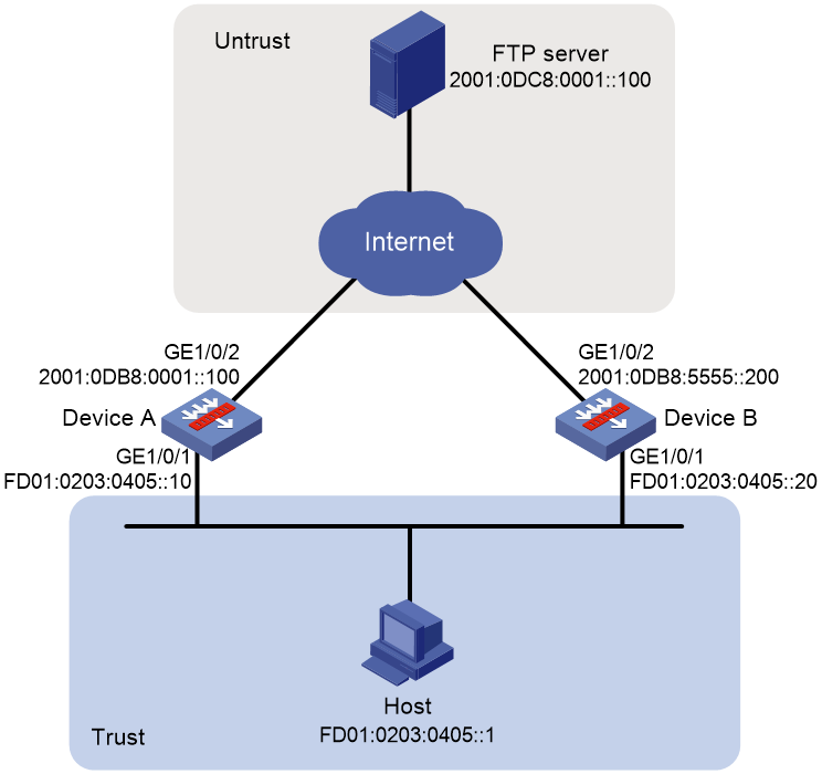
As shown in Figure 2, internal users use IPv6 prefix FD01:0203:0405::/48 and the internal IPv6 address is not routable on the Internet.
Device A and Device B are connected to the same internal network but different external networks. Configure IPv6 source prefix translation to translate the internal IPv6 prefix FD01:0203:0405::/48 to different external prefixes so that the internal address can be translated to two external addresses.
Procedure
1. Configure Device A.
a. Assign IPv6 addresses to interfaces:
# Assign an IPv6 address to interface GigabitEthernet 1/0/1.
<DeviceA> system-view
[DeviceA] interface gigabitethernet 1/0/1
[DeviceA-GigabitEthernet1/0/1] ipv6 address FD01:0203:0405::10 48
[DeviceA-GigabitEthernet1/0/1] quit
# Assign IPv6 addresses to other interfaces in the same way. (Details not shown.)
b. Configure settings for routing.
This example configures a static route, and the next hop in the route is 2001:0DB8:0001::11.
[DeviceA] ipv6 route-static 2001:0DC8:0001::100 48 2001:0DB8:0001::11
c. Add interfaces to security zones.
[DeviceA] security-zone name trust
[DeviceA-security-zone-Trust] import interface gigabitethernet 1/0/1
[DeviceA-security-zone-Trust] quit
[DeviceA] security-zone name untrust
[DeviceA-security-zone-Untrust] import interface gigabitethernet 1/0/2
[DeviceA-security-zone-Untrust] quit
d. Configure a security policy:
# Configure a rule named trust-untrust to permit the packets from the host to the FTP server.
[DeviceA] security-policy ipv6
[DeviceA-security-policy-ipv6] rule name trust-untrust
[DeviceA-security-policy-ipv6-1-trust-untrust] source-zone trust
[DeviceA-security-policy-ipv6-1-trust-untrust] destination-zone untrust
[DeviceA-security-policy-ipv6-1-trust-untrust] source-ip-host FD01:0203:0405::1
[DeviceA-security-policy-ipv6-1-trust-untrust] destination-ip-host 2001:0DC8:0001::100
[DeviceA-security-policy-ipv6-1-trust-untrust] action pass
[DeviceA-security-policy-ipv6-1-trust-untrust] quit
[DeviceA-security-policy-ipv6] quit
e. Configure IPv6 source prefix translation:
# Configure an IPv6 source prefix mapping from FD01:0203:0405::/48 to 2001:0DF8:0001::/48.
[DeviceA] interface gigabitethernet 1/0/2
[DeviceA-GigabitEthernet1/0/2] nat66 prefix source fd01:0203:0405:: 48 2001:0df8:0001:: 48
[DeviceA-GigabitEthernet1/0/2] quit
2. Configure Device B.
a. Assign IPv6 addresses to interfaces:
# Assign an IPv6 address to interface GigabitEthernet 1/0/1.
<DeviceB> system-view
[DeviceB] interface gigabitethernet 1/0/1
[DeviceB-GigabitEthernet1/0/1] ipv6 address FD01:0203:0405::20 48
[DeviceB-GigabitEthernet1/0/1] quit
# Assign IPv6 addresses to other interfaces in the same way. (Details not shown.)
b. Configure settings for routing.
This example configures a static route, and the next hop in the route is 2001:0DB8:5555::11.
[DeviceB] ipv6 route-static 2001:0DC8:0001::100 48 2001:0DB8:5555::11
c. Add interfaces to security zones.
[DeviceB] security-zone name trust
[DeviceB-security-zone-Trust] import interface gigabitethernet 1/0/1
[DeviceB-security-zone-Trust] quit
[DeviceB] security-zone name untrust
[DeviceB-security-zone-Untrust] import interface gigabitethernet 1/0/2
[DeviceB-security-zone-Untrust] quit
d. Configure a security policy:
# Configure a rule named trust-untrust to permit the packets from the host to the FTP server.
[DeviceB] security-policy ipv6
[DeviceB-security-policy-ipv6] rule name trust-untrust
[DeviceB-security-policy-ipv6-1-trust-untrust] source-zone trust
[DeviceB-security-policy-ipv6-1-trust-untrust] destination-zone untrust
[DeviceB-security-policy-ipv6-1-trust-untrust] source-ip-host FD01:0203:0405::1
[DeviceB-security-policy-ipv6-1-trust-untrust] destination-ip-host 2001:0DC8:0001::100
[DeviceB-security-policy-ipv6-1-trust-untrust] action pass
[DeviceB-security-policy-ipv6-1-trust-untrust] quit
[DeviceB-security-policy-ipv6] quit
e. Configure IPv6 source prefix translation:
# Configure an IPv6 source prefix mapping from FD01:0203:0405::/48 to 2001:0DE8:0001::/48.
[DeviceB] interface gigabitethernet 1/0/2
[DeviceB-GigabitEthernet1/0/2] nat66 prefix source fd01:0203:0405:: 48 2001:0de8:0001:: 48
[DeviceB-GigabitEthernet1/0/2] quit
Verifying the configuration
# Verify that the internal host can access the FTP server through Device A or Device B. The internal prefix is mapped to different external prefixes and external prefixes are mapped to the same internal prefix on the two NAT66 devices.
# Verify NAT66 configurations on Device A.
[DeviceA] display nat66 all
NAT66 source information:
Totally 1 source rules.
Interface(outbound): GigabitEthernet1/0/2
Original prefix/prefix-length: FD01:203:405::/48
Translated prefix/prefix-length: 2001:DF8:1::/48
# Verify NAT66 configurations on Device B.
[DeviceB] display nat66 all
NAT66 source information:
Totally 1 source rules.
Interface(outbound): GigabitEthernet1/0/2
Original prefix/prefix-length: FD01:203:405::/48
Translated prefix/prefix-length: 2001:DE8:1::/48
# Verify that NAT66 sessions are established on Device A.
[DeviceA] display nat66 session verbose
Slot 1:
Initiator:
Source IP/port: FD01:203:405::1/35990
Destination IP/port: 2001:DC8:1::100/21
VPN instance/VLAN ID/Inline ID: -/-/-
Protocol: TCP(6)
Inbound interface: GigabitEthernet1/0/1
Source security zone: Trust
Responder:
Source IP/port: 2001:DC8:1::100/21
Destination IP/port: 2001:DF8:1:D50F::1/35990
VPN instance/VLAN ID/Inline ID: -/-/-
Protocol: TCP(6)
Inbound interface: GigabitEthernet1/0/2
Source security zone: Trust
State: TCP_ESTABLISHED
Application: FTP
Rule ID: 0
Rule name: aaa
Start time: 2021-10-31 14:47:44 TTL: 3584s
Initiator->Responder: 0 packets 0 bytes
Responder->Initiator: 0 packets 0 bytes
Total sessions found: 1
# Verify that NAT66 sessions are established on Device B.
[DeviceB] display nat66 session verbose
Slot 1:
Initiator:
Source IP/port: FD01:203:405::1/35992
Destination IP/port: 2001:DC8:1::100/21
VPN instance/VLAN ID/Inline ID: -/-/-
Protocol: TCP(6)
Inbound interface: GigabitEthernet1/0/1
Source security zone: Trust
Responder:
Source IP/port: 2001:DC8:1::100/21
Destination IP/port: 2001:DE8:1:D51F::1/35992
VPN instance/VLAN ID/Inline ID: -/-/-
Protocol: TCP(6)
Inbound interface: GigabitEthernet1/0/2
Source security zone: Trust
State: TCP_ESTABLISHED
Application: FTP
Rule ID: 0
Rule name: aaa
Start time: 2021-10-31 14:50:03 TTL: 3594s
Initiator->Responder: 0 packets 0 bytes
Responder->Initiator: 0 packets 0 bytes
Total sessions found: 1
Example: Configuring IPv6 destination prefix translation
Network configuration
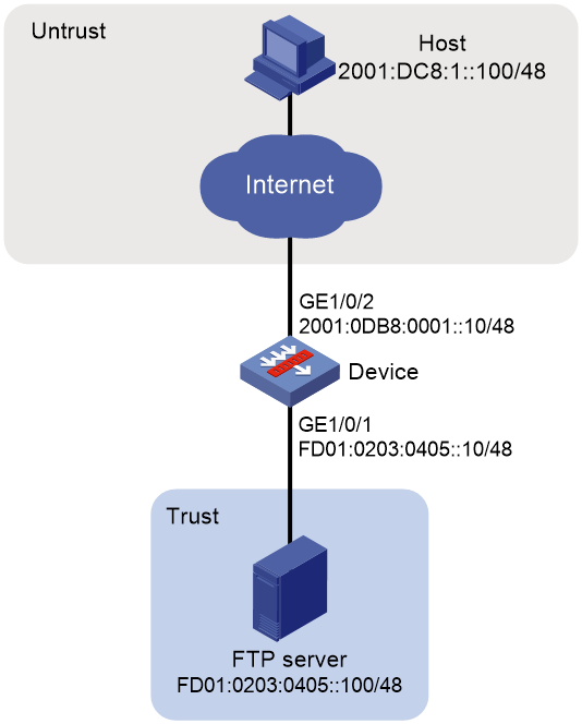
As shown in Figure 3, the internal IPv6 address of FTP server is FD01:0203:0405::100/48. The internal prefix is FD01:0203:0405::/48. Configure destination IPv6 prefix translation to allow the FTP server to use IPv6 address 2001:AB01:0001::1 to provide services for external users.
Procedure
1. Assign IPv6 addresses to interfaces:
# Assign an IPv6 address to interface GigabitEthernet 1/0/1.
<Device> system-view
[Device] interface gigabitethernet 1/0/1
[Device-GigabitEthernet1/0/1] ipv6 address FD01:0203:0405::10 48
[Device-GigabitEthernet1/0/1] quit
# Assign IPv6 addresses to other interfaces in the same way. (Details not shown.)
2. Add interfaces to security zones.
[Device] security-zone name trust
[Device-security-zone-Trust] import interface gigabitethernet 1/0/1
[Device-security-zone-Trust] quit
[Device] security-zone name untrust
[Device-security-zone-Untrust] import interface gigabitethernet 1/0/2
[Device-security-zone-Untrust] quit
3. Configure a security policy:
# Configure a rule named untrust-trust to permit the packets from the hosts in the external network to the FTP server in the Trust security zone.
[Device] security-policy ipv6
[Device-security-policy-ipv6] rule 1 name untrust-trust
[Device-security-policy-ipv6-1-untrust-trust] source-zone untrust
[Device-security-policy-ipv6-1-untrust-trust] destination-zone trust
[Device-security-policy-ipv6-1-untrust-trust] destination-ip-host FD01:0203:0405::100
[Device-security-policy-ipv6-1-untrust-trust] action pass
[Device-security-policy-ipv6-1-untrust-trust] quit
[Device-security-policy-ipv6] quit
4. Configure IPv6 destination prefix translation:
# Configure an IPv6 destination prefix mapping from 2001:AB01:0001::1/128 to FD01:0203:0405::100/128.
[Device] interface gigabitethernet 1/0/2
[Device-GigabitEthernet1/0/2] nat66 prefix destination 2001:ab01:1::1 128 fd01:203:405::100 128
[Device-GigabitEthernet1/0/2] quit
Verifying the configuration
# Verify that external hosts can access the FTP server. (Details not shown.)
# Verify NAT66 configurations.
[Device] display nat66 all
NAT66 destination information:
Totally 1 destination rules.
Interface(inbound): GigabitEthernet1/0/2
Original prefix/prefix-length: 2001:AB01:1::1/128
Translated prefix/prefix-length: FD01:203:405::100/128
# Verify that NAT66 sessions are established.
[Device] display nat66 session verbose
Slot 1:
Initiator:
Source IP/port: 2001:DC8:1::100/9025
Destination IP/port: 2001:AB01:1::1/21
VPN instance/VLAN ID/Inline ID: -/-/-
Protocol: TCP(6)
Inbound interface: GigabitEthernet1/0/2
Source security zone: Untrust
Responder:
Source IP/port: FD01:203:405::100/21
Destination IP/port: 2001:DC8:1::100/9025
VPN instance/VLAN ID/Inline ID: -/-/-
Protocol: TCP(6)
Inbound interface: GigabitEthernet1/0/1
Source security zone: Trust
State: TCP_ESTABLISHED
Application: FTP
Rule ID: 1
Rule name: 1
Start time: 2018-12-06 14:56:03 TTL: 3579s
Initiator->Responder: 0 packets 0 bytes
Responder->Initiator: 0 packets 0 bytes
Total sessions found: 1