- Table of Contents
- Related Documents
-
| Title | Size | Download |
|---|---|---|
| 01-Text | 2.07 MB |
Plan the IP address assignment scheme
Deploy the simulation service on the analyzer
Preconfigure the simulation network
Introduction
The simulation technique is used to synchronize the device configuration, network topology, and traffic information on the production network, and parse and restore the topology and protocols of the whole network based on synchronized information. By specifying the key network devices, link faults, and traffic optimization for the network, you can enable the simulation system to analyze the traffic and failure points of the network and their impacts on services. The simulation system provides data for deep analysis and maintenance of the network. The network simulation analysis feature includes the following functions: topology display, traffic simulation analysis, and failure simulation analysis.
This document describes how to deploy the DTN hosts and build a simulation network on the analyzer.
Environment setup workflow
Table 1 shows the workflow to set up a simulation environment.
Table 1 Environment deployment workflow
|
Step |
Tasks |
|
Deploy the SeerAnalyzer-Simulation and DTN components |
See H3C SeerAnalyzer Installation and Deployment Guide. |
Plan the network
Plan network topology
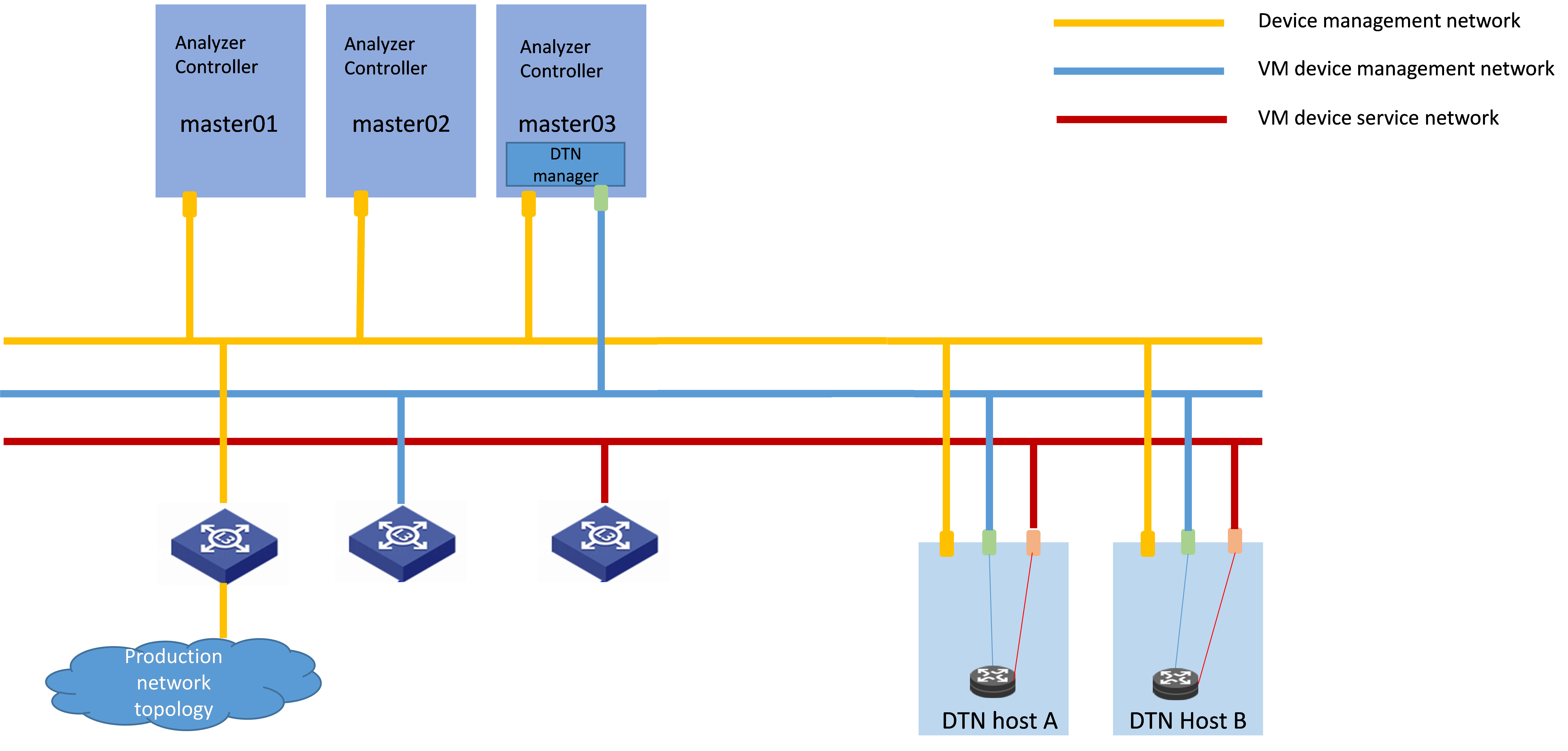
A simulation network includes three types of networks, including device management network, VM device management network, and VM device service network.
· Device management network—Network for cluster communication between analyzers and device management.
· VM device management network—Network over which the digital twin network (DTN) microservice component and DTN hosts exchange management information.
· VM device service network—Network over which the DTN hosts exchange service data.
Before you deploy the simulation system, plan the VM device management network and VM device service network.
Figure 1 Typical simulation network topology design for the carrier network scenario in non-remote disaster recovery mode
|
|
CAUTION: · If the device management network and VM device management network use the same management switch, configure VPN instances for isolation on the management switch to isolate the VM device management network from the production network and prevent IP address conflicts from affecting the services. If the device management network and VM device management network use different management switches, physically isolate these switches. · Configure routes to provide Layer 3 connectivity between simulation management IPs and simulated device management IPs. · On the port connecting the switch to the service interface of a simulation host, execute the port link-type trunk command to configure the link type of the port as trunk, and execute the port trunk permit vlan vlan-id-list command to assign the port to 150 contiguous VLAN IDs. Among these VLAN IDs, the start ID is the VLAN ID specified when installing the DTN host, and the end VLAN ID is the start VLAN ID+149. For example, if the start VLAN ID is 11, the permitted VLAN ID range is 11 to 160. When you plan the network, do not use any VLAN ID permitted by the port. |
Plan the IP address assignment scheme
As a best practice, use Table 2 to calculate the minimum number of IP addresses on subnets in each network for deployment of a SeerEngine-DC controller cluster and DTN Manager.
Table 2 Number of addresses in subnet IP address pools
|
Component/Node name |
Network name (type) |
Max number of cluster members |
Default number of cluster members |
Calculation method |
Remarks |
|
SeerAnalyzer-Simulation |
VM device management network |
1 |
1 |
Single node deployment, which requires two IPs. |
N/A |
|
DTN component |
VM device management network |
1 |
1 |
Single node deployment, which requires only one IP. |
Used by the simulation microservice deployed on the analyzer node |
|
DTN host |
VM device management network |
Number of DTN hosts |
Number of DTN hosts |
Number of DTN hosts |
Used by the DTN microservice component to incorporate DTN hosts |
|
VM device interconnect network |
Number of DTN hosts |
Number of DTN hosts |
Number of DTN hosts |
Tunnel encapsulation address for service communication between simulation hosts. |
This document uses the IP address plan in Table 3 for example.
Table 3 IP address plan example
|
Component/node name |
Network name (type) |
IP address |
|
SeerAnalyzer-Simulation |
VM device management network |
Subnet: 192.168.12.0 (gateway address: 192.168.12.1) |
|
Network address pool: 192.168.12.101 to 192.168.12.102 |
||
|
DTN component |
VM device management network |
Subnet: 192.168.12.0 (gateway address: 192.168.12.1) |
|
Network address pool: 192.168.12.133 to 192.168.12.133 |
||
|
DTN host |
Device management network |
Network address pool: 192.168.12.134 to 192.168.12.144 |
|
VM device service network |
Network address pool: 192.168.11.134 to 192.168.11.144 |
|
|
IMPORTANT: The VM device management network and VM device service network of a DTN host must be on different network segments. |
Deploy DTN hosts
Server requirements
Hardware requirements
For the hardware requirements for the DTN hosts and DTN components, see AD-NET Solution Hardware Configuration Guide.
Software requirements
The DTN hosts must install an operating system that meets the requirements in Table 4.
Table 4 Operating systems and versions supported by the host
|
OS name |
Version number |
Kernel version |
|
H3Linux |
V1.3.1 |
5.10 |
Install the operating system
H3Linux operating system
|
|
CAUTION: Before you install H3Linux on a server, back up server data. H3Linux will replace the original OS (if any) on the server with data removed. |
The H3Linux_K510_version.iso (where version is the version number) image is the H3Linux operating system installation package. The following information uses a server without an OS installed for example to describe the installation procedure of the H3Linux_K510_version.iso image.
1. Obtain the required H3Linux_K510_version.iso image in ISO format.
2. Access the remote console of the server, and then mount the ISO image as a virtual optical drive.
3. Configure the server to boot from the virtual optical drive, and then restart the sever.
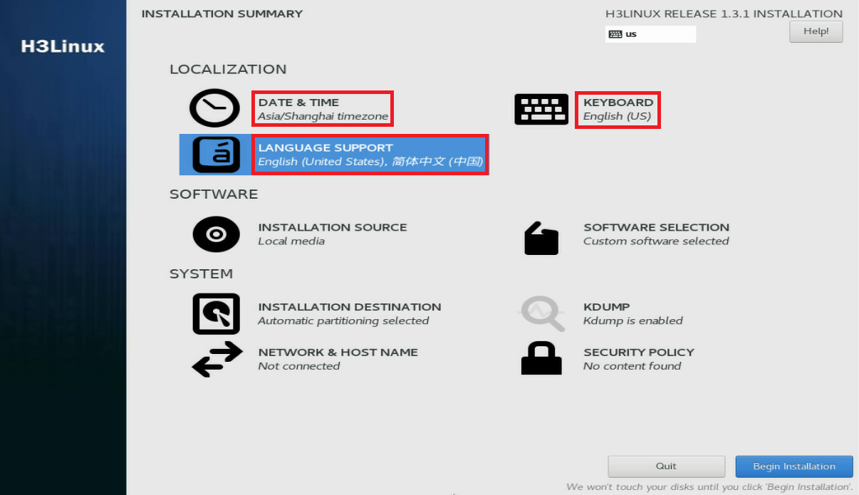
After the ISO image is loaded, the INSTALLATION SUMMARY page opens.
Figure 2 INSTALLATION SUMMARY page

4. In the LOCALIZATION area, perform the following steps:
¡ Click DATE & TIME to modify the date and time settings.
¡ Click KEYBOARD to modify keyboard settings as needed.
¡ Click LANGUAGE SUPPORT to select your preferred language.
|
|
IMPORTANT: Make sure you select the same time zone across the hosts. In this document, [Asia/Shanghai] is selected for example. |
Figure 3 INSTALLATION SUMMARY page
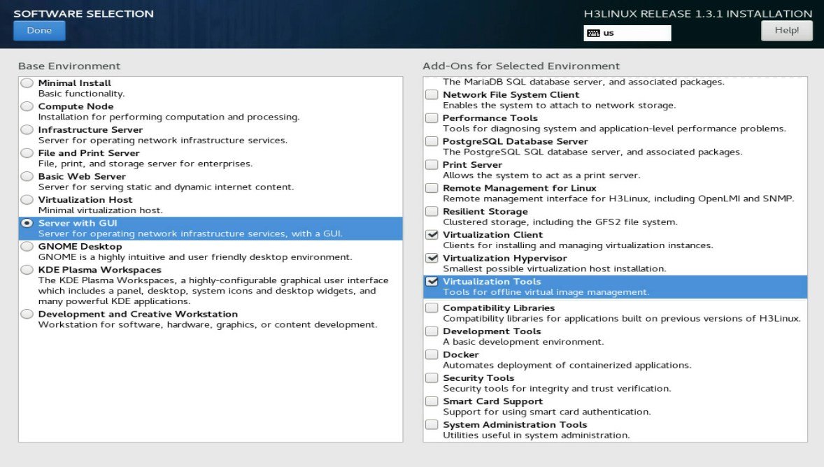
5. Click SOFTWARE SELECTION in the SOFTWARE area to enter the page for selecting software. Select the Server with GUI base environment and the File and Storage Server, Virtualization Client, Virtualization Hypervisor, and Virtualization Tools add-ons. Then, click Done to return to the INSTALLATION SUMMARY page.
Figure 4 SOFTWARE SELECTION page (1)
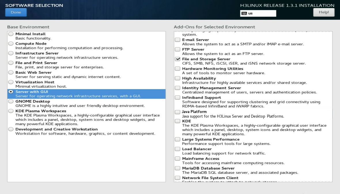
Figure 5 SOFTWARE SELECTION page (2)
6. In the SYSTEM area, click INSTALLATION DESTINATION.
Figure 6 INSTALLATION DESTINATION dialog box

7. In the dialog box that opens, perform the following operations:
a. Select a local disk from the Local Standard Disks area.
b. In the Other Storage Options area, select I will configure partitioning.
c. Click Done.
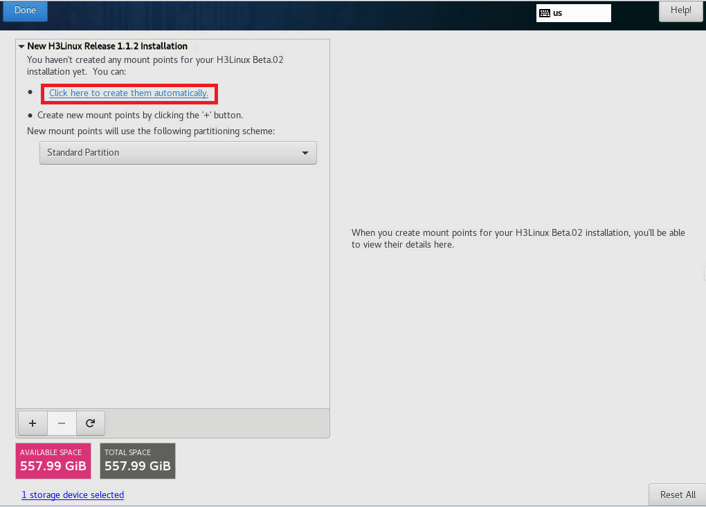
8. In the MANUAL PARTITIONING dialog box, click Click here to create them automatically to automatically generate recommended partitions.
Figure 7 MANUAL PARTITIONING dialog box
The list of automatically created partitions opens. Figure 8 shows the list of automatically created partitions when the disk size is 600 GiB.
|
|
IMPORTANT: The /boot/efi partition is available only if UEFI mode is enabled for OS installation. |
Figure 8 Automatically created partition list
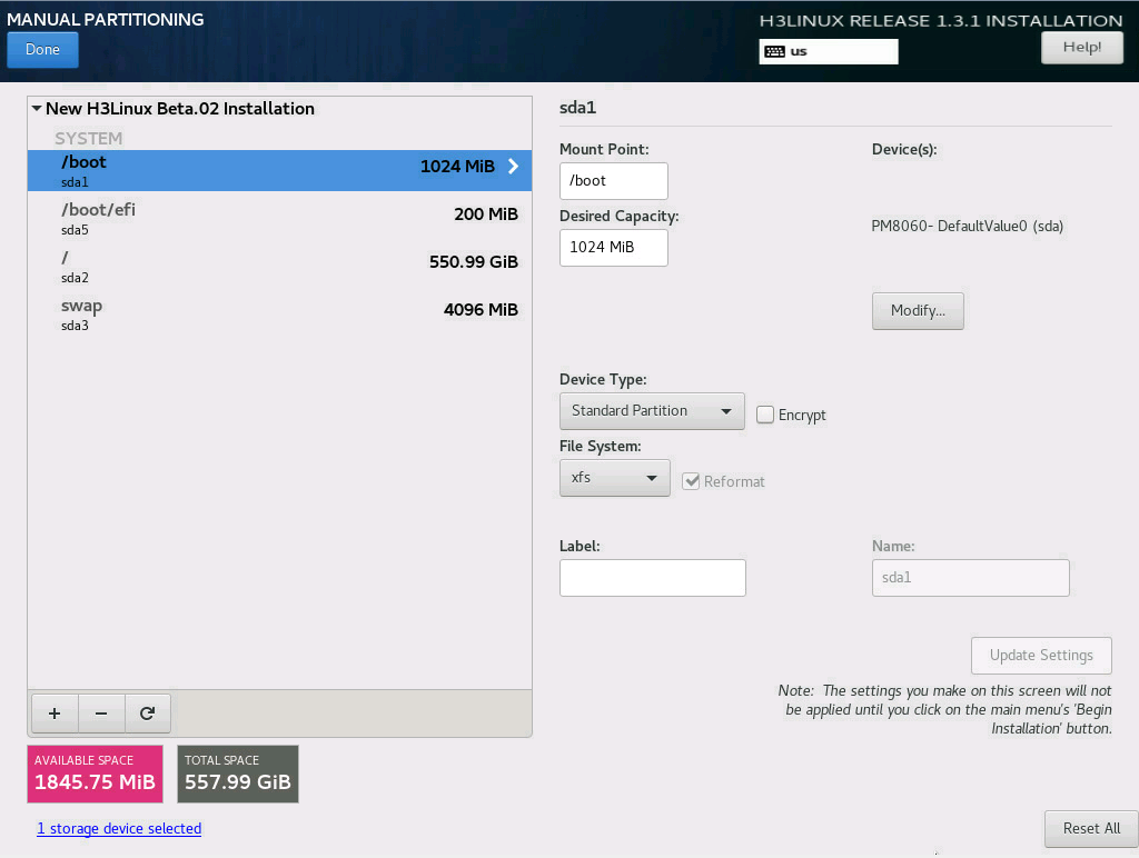
9. Set the device type and file system of a partition. As a best practice, set the device type to Standard Partition to improve system stability. Table 5 shows the device type and file system of each partition used in this document.
|
Partition name |
Device type |
File system |
|
/boot |
Standard Partition |
xfs |
|
/boot/efi (UEFI mode) |
Standard Partition |
EFI System Partition |
|
/ |
Standard Partition |
xfs |
|
/swap |
Standard Partition |
swap |
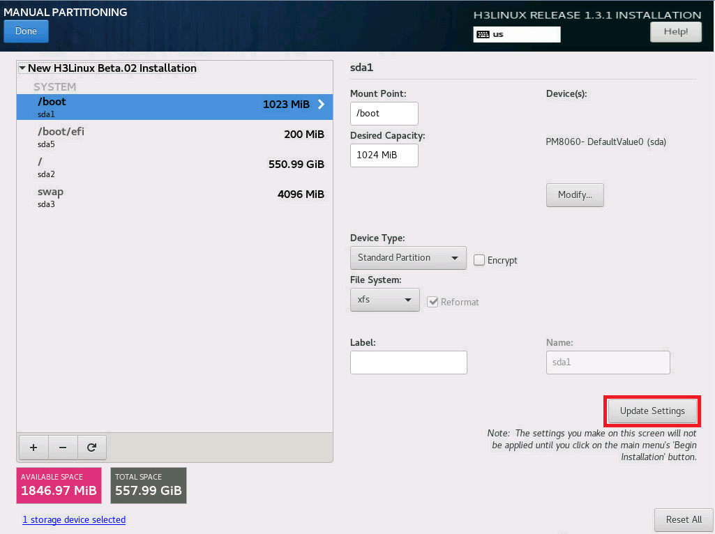
10. Edit the device type and file system of a partition as shown in Table 6. Take the /boot partition for example. Select a partition on the left, and select Standard Partition from the Device Type list and xfs from the File System list. Then, click Update Settings.
Table 6 Configuring partitions
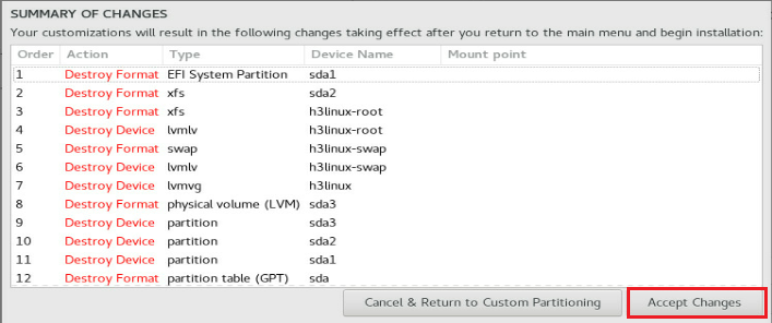
11. After you finish the partitioning task, click Done in the upper left corner. In the dialog box that opens, select Accept Changes.
Figure 9 Accepting changes
12. In the INSTALLATION SUMMARY window that opens, click NETWORK & HOSTNAME in the SYSTEM area to configure the host name and network settings.
13. In the Host name field, enter the host name (for example, host01) for this server, and then click Apply.
Figure 10 Setting the host name

14. Configure the network settings:
|
|
IMPORTANT: Configure network ports as planned. The server requires a minimum of three network ports. In “Deploy the DTN host,” two network ports will be virtualized into bridges mge_bridge and brvlan-{vlanId}. The network port bound to bridge mge_bridge must be configured with an IP address used for communication between the analyzer and DTN component. The third network port must be configured with the management IP of the DTN host node and is used for routine server maintenance. |
a. Select a network port and then click Configure.
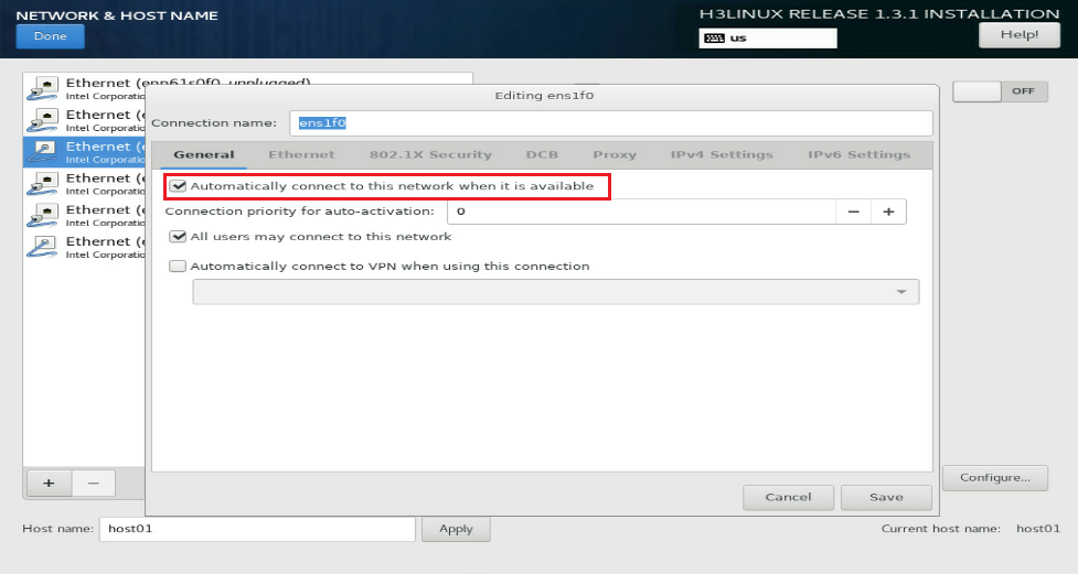
b. In the dialog box that opens, configure basic network port settings on the General tab:
- Select the Automatically connect to this network when it is available option .
- Verify that the All users may connect to this network option is selected. By default, this option is selected.
Figure 11 General settings for a network port
15. Configure IP address settings:
a. Click the IPv4 Settings or IPv6 Settings tab.
b. From the Method list, select Manual.
c. Click Add, assign a simulation management IP address to the DTN host, and then click Save.
d. Click Done in the upper left corner of the dialog box.
|
|
IMPORTANT: DTN service supports IPv4 and IPv6. In the current software version, only a single stack is supported. |
Figure 12 Configuring IPv4 address settings for a network port

16. Repeat Step 14 and Step 15 to configure the management IP addresses for other DTN hosts. The IP addresses must be in the network address pool containing IP addresses 192.168.10.110 to 192.168.10.120, for example, 192.168.10.110.
17. Click Begin Installation to install the OS.
18. During the installation, configure the root password as prompted:
|
|
IMPORTANT: You must configure a root password before you can continue with the installation. |
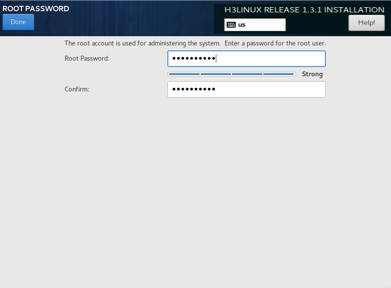
a. In the USER SETTINGS area, click ROOT PASSWORD.
b. In the dialog box that opens, set the root password for the system, and then click Done in the upper left corner.
Figure 13 Configuration window for H3Linux OS installation
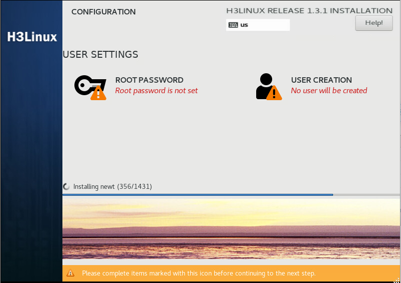
Figure 14 Setting the root password
Then, the system automatically reboots to finish OS installation.
Deploy the DTN hosts
|
|
CAUTION: · Execution of the DTN host installation script will cause the network service to restart and the SSH connection to disconnect. To avoid this situation, configure the DTN host from the remote console of the server. · When the DTN host management network and DTN component management network are deployed across a Layer 3 network, the route configuration will be reset after you execute the installation script. As a best practice to avoid manually re-adding routes, make the static route persistent. |
1. Obtain the DTN host installation package, upload it to the server, and then decompress it. The installation package is named in the DTN_HOST-version.zip format.
[root@host01 root]# unzip DTN_HOST-E6502.zip
2. Execute the chmod command to assign permissions to the user.
[root@host01 root]# chmod +x -R DTN_HOST-E6502
3. Access the DTN_HOST-version/ directory of the decompressed installation package, and execute the ./install.sh management_nic service_nic vlan_start service_cidr command to install the package.
Parameters:
management_nic: Specify the network port name for the simulation management interface.
service_nic: Specify the network port name for the simulation service interface.
vlan_start: Specify the start VLAN ID.
service_cidr: Specify the CIDR for service communication among hosts.
[root@host01 DTN_HOST-E6502]# ./install.sh ens1f0 ens1f1 11 6.7.7.9/24
Installing ...
check network service ok.
check libvirtd service ok.
check management bridge ok.
check sendip ok.
check vconfig ok.
check vlan interface ok.
Complete!
|
|
IMPORTANT: · The CIDRs used for service communication between hosts must be on the same network segment and support IPv4. · VLANs are used for service isolation and are in the range of vlan_start to vlan_start+149 and must be the same on all hosts. |
When the DTN host management network and DTN component management network are deployed across a Layer 3 network, you must perform the following tasks on the DTN host.
1. Add the static route to the DTN component management network.
[root@host01 ~]# route add -host 192.168.13.133 dev mge_bridge
2. Make the static route to the DTN component management network persistent.
[root@host01 ~]#cd etc/sysconfig/network-scripts/
[root@host01 network-scripts]# vi route-ens1f0
Enter 192.168.13.133/32 via 192.168.12.1 dev mge_bridge in the file. Then, save and exit the file.
[root@host01 network-scripts]# cat route-ens1f0
192.168.13.133/32 via 192.168.12.1 dev mge_bridge
Deploy the simulation service on the analyzer
|
|
CAUTION: Make sure the SeerAnalyzer-WAN and DTN-Manager components have been deployed. For the deployment procedure, see H3C SeerAnalyzer Installation and Deployment Guide. |
Preconfigure the analyzer
Preconfigure SeerAnalyzer as shown in Table 7. This section describes only basic settings for the WAN scenario.
Table 7 Preconfiguring SeerAnalyzer
|
Configuration |
Menu path |
|
Asset management |
Analytics > Analysis Options > Resources > Assets |
|
NETCONF collection template |
Analytics > Analysis Options > Collector > Template Management |
|
NETCONF protocol template |
Analytics > Analysis Options > Collector > Template Management |
|
Connect devices on topology |
Analytics > Analysis Options > Global Configure |
|
View topology |
Analytics > Analysis Options > Global Configure |
Preconfigure the simulation network
· Managing simulation host—A host refers to a physical server installed with an H3Linux system and configured with related settings. The simulated devices in the simulation network model are created on the host. If multiple hosts are available, the analyzer selects a host with optimal resources for creating simulated devices.
· Managing simulation images—Upload the images of physical devices on the production network to build the corresponding simulated devices.
· Configuring parameters—The connections between simulated devices are UDP tunnels. Therefore, you must set the UDP port numbers.
|
|
NOTE: The simulation network building modes include Build Whole Network and Build On Demand. · Build Whole Network—Use this mode when the production network topology is not complicated. The system will build a vDevice network topology in a 1:1 ratio to the production network topology, enabling a more realistic simulation of the production network topology. · Build On Demand—To save resources when the production network topology is large-scaled, you can build a simulation network only for the critical device network topology. The permissions to manage the simulation network are assigned by the administrator. |
Manage simulation hosts
|
|
CAUTION: · A host can be incorporated by only one WAN analyzer cluster. · DTN hosts incorporated on the analyzer support only the root user. |
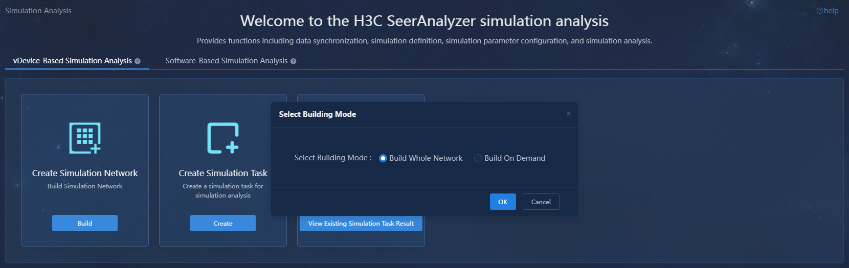
1. Log in to the system as a user that has permissions to manage the simulation network. Navigate to the Analytics > Simulation Analysis > vDevice-Based Simulation Analysis page. Click Build in the Create Simulation Network area. In the dialog box that opens, select a building mode.
Figure 15 Selecting a building mode

2. Click Build on the page that opens. In the dialog box that opens, click the preconfiguring the simulation network link. The Manage Simulation Hosts tab is displayed by default.
Figure 16 Managing simulation hosts
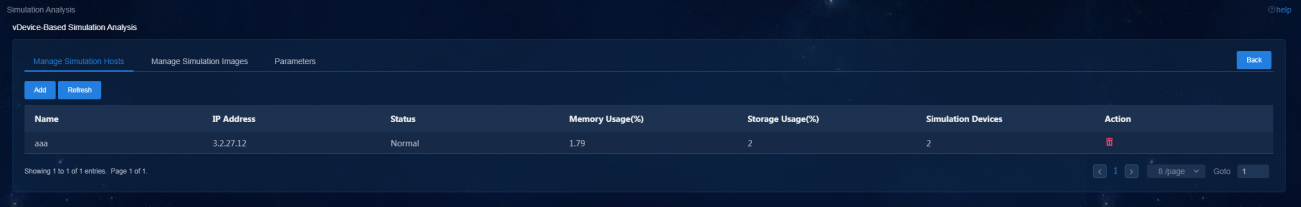
3. Click Add. In the dialog box that opens, configure the host name, IP address, username, and password.
Parameters
¡ Name: Name of the DTN host.
¡ IP Address: Management IP of the DTN host.
¡ Username: Username for logging in to the host.
¡ Password: Password for logging in to the host.
Figure 17 Adding a host
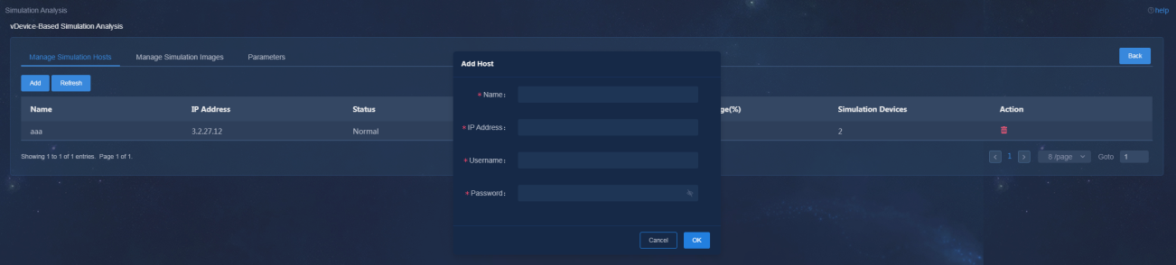
4. Click OK.
Manage simulation images
1. Log in to the system as a user that has permissions to manage the simulation network. Navigate to the Analytics > Simulation Analysis > vDevice Simulation Analysis page. Click Build in the Create Simulation Network area. In the dialog box that opens, select a building mode.
2. Click Build on the page that opens. In the dialog box that opens, click the preconfiguring the simulation network link. The Manage Simulation Hosts tab is displayed by default.
3. Click the Manage Simulation Images tab.
Figure 18 Managing simulation images
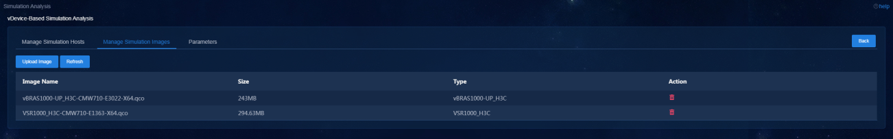
4. Click Upload Image. In the dialog box that opens, select an image type and then an image of the corresponding type.
Figure 19 Uploading a simulation image
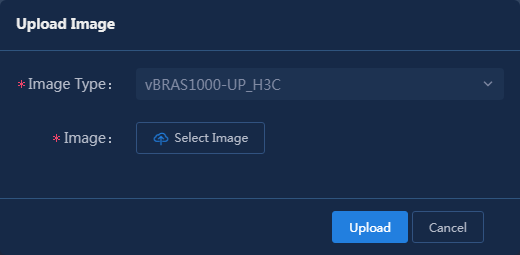
5. Click Upload.
Configure parameters
1. Log in to the system as a user that has permissions to manage the simulation network. Navigate to the Analytics > Simulation Analysis > vDevice Simulation Analysis page. Click Build in the Create Simulation Network area. In the dialog box that opens, select a building mode.
2. Click Build on the page that opens. In the dialog box that opens, click the preconfiguring the simulation network link. The Manage Simulation Hosts tab is displayed by default.
3. Click the Parameters tab.
Figure 20 Parameters
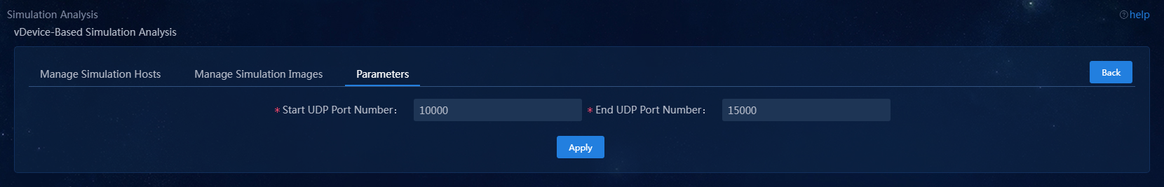
4. Configure the following parameters as needed.
5. Click Apply.
Build a simulation network
|
|
CAUTION: To rebuild a simulation network, you must reinstall licenses for all simulated devices. The simulation network building modes include Build Whole Network and Build On Demand. · Build Whole Network—Use this mode when the production network topology is not complicated. The system will build a vDevice network topology in a 1:1 ratio to the production network topology, enabling a more realistic simulation of the production network topology. · Build On Demand—To save resources when the production network topology is large-scaled, you can build a simulation network only for the critical device network topology. |
After preconfiguring the simulation network and analyzer, you can build a simulation network.
To build a simulation network:
1. Log in to the system as a user that has permissions to manage the simulation network. Navigate to the Analytics > Simulation Analysis > vDevice Simulation Analysis page. Click Build in the Create Simulation Network area. In the dialog box that opens, select a building mode.
Figure 21 Selecting a building mode
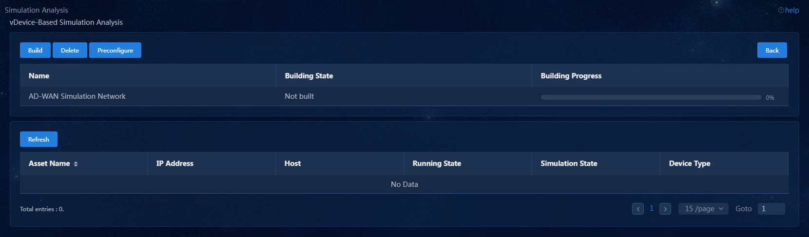
2. After selecting the building mode, click OK to access the vDevice-Based Simulation Analysis page.
Figure 22 vDevice-based simulation analysis page for building the whole network
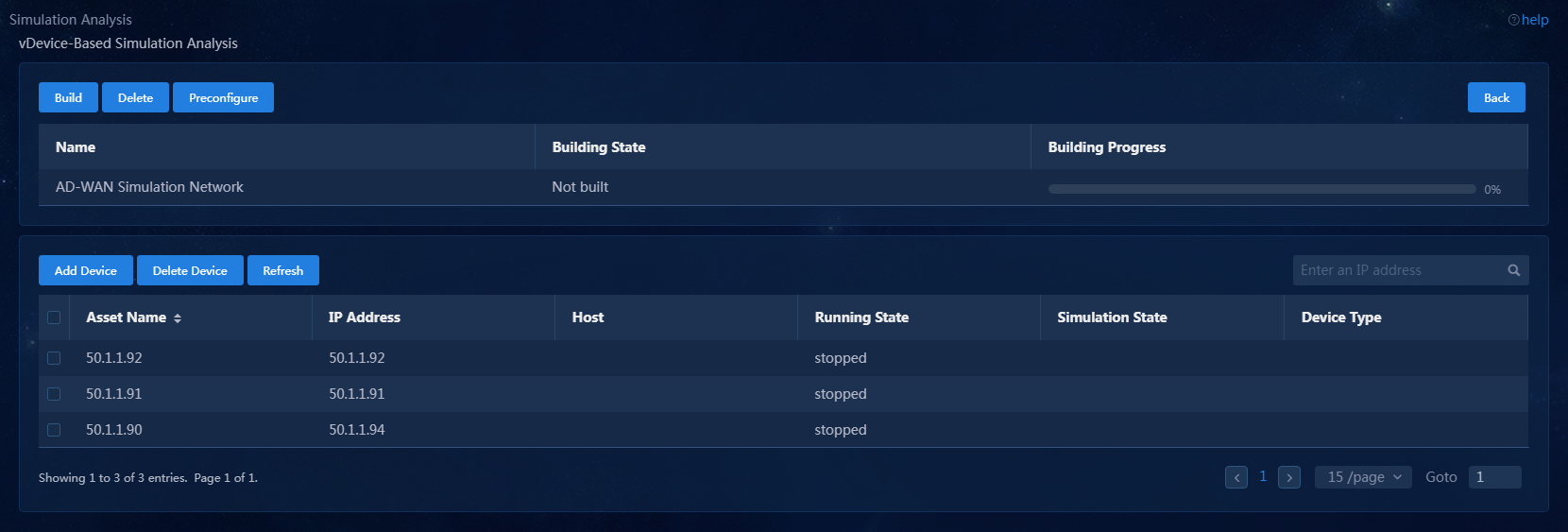
If you select the Build On Demand option, add devices as needed on the page as shown in Figure 23.
Figure 23 Building a simulation network on demand
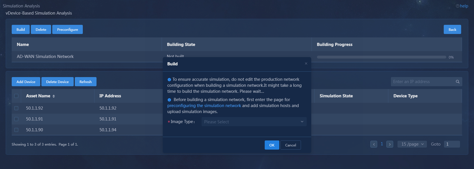
3. Click Build on the page that opens. In the dialog box that opens, select an image type and then click OK to start building the simulation network.
Figure 24 Build a simulation network
4. During the process of building a simulation network, view the building progress.
Figure 25 Simulation network building progress
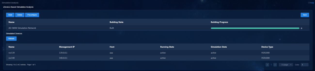
5. After the simulation network is built successfully, you can view the simulated device information:
¡ The simulated device running state is Active.
¡ The device model is displayed correctly on the production network and the simulation network.
The VMs in the simulation network model are created on the host created. If multiple hosts are available, the simulation service selects a host with optimal resources for creating VMs.
Upgrade and uninstall the DTN hosts
Upgrade a DTN host
|
|
NOTE: As from version E6502 and later of the analyzer, you do not need to separately deploy a simulation analysis server. This releases one server resource when you upgrade the analyzer to a later version. |
1. Obtain the new version of the DTN host installation package, upload it to the server, and decompress it. The package is named in the DTN_HOST-version.zip format.
[root@host01 root]# unzip DTN_HOST-E6502.zip
2. Execute the chmod command to assign permissions to the user.
[root@host01 root]# chmod +x -R DTN_HOST-E6502
3. Access the DTN_HOST-version/ directory of the decompressed installation package, and then execute the ./upgrade.sh command to upgrade the host.
[root@host01 DTN_HOST-E6502]# ./upgrade.sh
check network service ok.
check libvirtd service ok.
check management bridge ok.
check sendip ok.
check vconfig ok.
check vlan interface ok.
Complete!
Uninstall a DTN host
|
|
IMPORTANT: Execution of the DTN host uninstall script will cause the network service to restart and the SSH connection to disconnect. To avoid this situation, uninstall a DTN host from the remote console of the server. |
To uninstall a host, access the DTN_HOST-version/ directory and execute the ./uninstall.sh command.
[root@host01 DTN_HOST-E6502]# ./uninstall.sh
Uninstalling ...
Bridge rollback succeeded.
Restarting network,please wait.
