- Table of Contents
-
- 12-Network Management and Monitoring Configuration Guide
- 00-Preface
- 01-System maintenance and debugging configuration
- 02-NQA configuration
- 03-iNQA configuration
- 04-NTP configuration
- 05-PTP configuration
- 06-Network synchronization configuration
- 07-PoE configuration
- 08-SNMP configuration
- 09-RMON configuration
- 10-NETCONF configuration
- 11-Ansible configuration
- 12-SmartMC configuration
- 13-EPA configuration
- 14-CWMP configuration
- 15-EAA configuration
- 16-Process monitoring and maintenance configuration
- 17-Sampler configuration
- 18-Mirroring configuration
- 19-NetStream configuration
- 20-IPv6 NetStream configuration
- 21-NetAnalysis configuration
- 22-sFlow configuration
- 23-Information center configuration
- 24-GOLD configuration
- 25-Packet capture configuration
- 26-VCF fabric configuration
- 27-Cloud connection configuration
- 28-EPS agent configuration
- 29-SQA configuration
- 30-eMDI configuration
- 31-Performance management configuration
- 32-TCP connection trace configuration
- Related Documents
-
| Title | Size | Download |
|---|---|---|
| 07-PoE configuration | 217.22 KB |
Contents
Restrictions: Hardware compatibility with PoE
Restrictions and guidelines: PoE configuration
PoE configuration tasks at a glance
Prerequisites for configuring PoE
Disabling PoE on shutdown interfaces
Allowing inrush currents drawn by PDs
Enabling PI power cycling upon a system warm reboot
Enabling nonstandard PD detection
Configuring the maximum PoE power
Configuring the maximum PSE power
Configuring the maximum PI power
Configuring the PoE priority policy
Configuring the PSE priority policy
Configuring the PI priority policy
Configuring PSE power monitoring
Configuring a PI by using a PoE profile
Upgrading PSE firmware in service
Display and maintenance commands for PoE
Failure to set the priority of a PI to critical
Failure to apply a PoE profile to a PI
Configuring PoE
About PoE
Power over Ethernet (PoE) enables a network device to supply power to terminals over twisted pair cables.
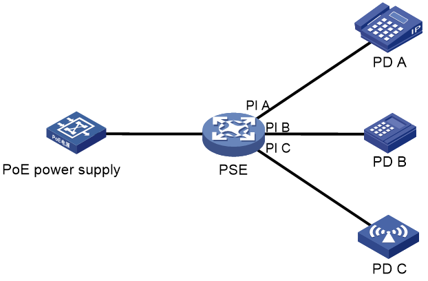
PoE system
As shown in Figure 1, a PoE system includes the following elements:
· PoE power supply—A PoE power supply provides power for the entire PoE system.
· PSE—A power sourcing equipment (PSE) supplies power to PDs. PSE devices are classified into single-PSE devices and multiple-PSE devices.
¡ A single-PSE device has only one piece of PSE firmware.
¡ A multiple-PSE device has multiple PSEs. A multiple-PSE device uses PSE IDs to identify different PSEs. To view the mapping between the ID and slot number of a PSE, execute the display poe device command.
The device is a multiple-PSE device.
· PI—A power interface (PI) is a PoE-capable Ethernet interface on a PSE.
· PD—A powered device (PD) receives power from a PSE. PDs include IP telephones, APs, portable chargers, POS terminals, and Web cameras. You can also connect a PD to a redundant power source for reliability.
Protocols and standards
802.3af, 802.3at, and 802.3bt are the 3rd, 4th, and 5th editions of the PoE protocol established by the IEEE. The differences between the three PoE technologies lie in their power transmission capabilities and the number of wires used for power transmission.
· 802.3af, also known as the PoE standard, was released in 2003. It provides a maximum power output of 15.4 W and uses 2 pairs of wires for power transmission.
The name of the 802.3af standard is 802.3af-2003, IEEE Standard for Information Technology - Telecommunications and Information Exchange Between Systems - Local and Metropolitan Area Networks - Specific Requirements - Part 3: Carrier Sense Multiple Access with Collision Detection (CSMA/CD) Access Method and Physical Layer Specifications - Data Terminal Equipment (DTE) Power Via Media Dependent Interface (MDI).
· 802.3at, also known as the PoE+ standard, was released in 2009. It provides a maximum power output of 30 W and uses 2 or 4 pairs of wires for power transmission. It is backward compatible with the 802.3af standard.
The name of the 802.3at standard is 802.3at-2009, IEEE Standard for Information technology-- Local and metropolitan area networks-- Specific requirements-- Part 3: CSMA/CD Access Method and Physical Layer Specifications Amendment 3: Data Terminal Equipment (DTE) Power via the Media Dependent Interface (MDI) Enhancements.
· 802.3bt, also known as the PoE++ standard, was released in 2018. It provides a maximum power output of 90 W and is compatible with existing low-power PoE devices. This standard uses 4 pairs of wires for power transmission and supports PoE devices over long distances and with better performance. It is backward compatible with the 802.3af and 802.3at standards.
The name of the 802.3bt standard is 802.3bt-2018 - IEEE Standard for Ethernet Amendment 2: Physical Layer and Management Parameters for Power over Ethernet over 4 pairs.
Restrictions: Hardware compatibility with PoE
Only the S7506X-G-PoE and S7510X-G-PoE switches installed with the LSCM2GV48SC0 or LSCM2GV48SD0 interface module support PoE.
Restrictions and guidelines: PoE configuration
|
|
CAUTION: When a PI is IEEE 802.3at- or IEEE 802.3bt compliant, it supplies power to the PD only if the total remaining power of all PSEs is greater than or equal to the guard band. To obtain the total remaining power of all PSEs, execute the display poe interface without specifying an interface. The value of the Remaining field is the total remaining power of all PSEs. The guard band value depends on the PoE standard and software version. |
You can configure settings for a PI through either of the following ways:
· Configure the settings directly on the PI.
· Configure a PoE profile and apply it to the PI. If you apply a PoE profile to multiple PIs, these PIs have the same PoE features. If you connect a PD to another PI, you can apply the PoE profile of the original PI to the new PI. This method relieves the task of configuring PoE on the new PI.
You can only use one way to configure a parameter for a PI. To use the other way to reconfigure a parameter, you must first remove the original configuration.
You must use the same configuration method for the poe max-power max-power and poe priority { critical | high | low } commands.
PoE configuration tasks at a glance
To configure PoE, perform the following tasks:
1. Enabling PoE
2. (Optional.) Enabling fast PoE for a PSE
3. (Optional.) Configuring PoE delay
4. (Optional.) Disabling PoE on shutdown interfaces
5. (Optional.) Enabling PI power cycling upon a system warm reboot
6. (Optional.) Configuring PD detection
¡ Enabling nonstandard PD detection
7. (Optional.) Configuring the PoE power
¡ Configuring the maximum PoE power
¡ Configuring the maximum PSE power
¡ Configuring the maximum PI power
8. (Optional.) Configuring the PoE priority policy
¡ Configuring the PSE priority policy
¡ Configuring the PI priority policy
9. (Optional.) Configuring PoE monitoring
¡ Configuring PSE power monitoring
10. (Optional.) Configuring a PI by using a PoE profile
To use a PoE profile to enable PoE and configure the priority, power transmission mode, and maximum power for a PI, see "Configuring a PI by using a PoE profile."
11. (Optional.) Upgrading PSE firmware in service
Prerequisites for configuring PoE
Before you configure PoE, make sure the PoE power supply and PSEs are operating correctly.
Enabling PoE
Enabling PoE for a PSE
About this task
The device that supports dynamic power allocation supplies power to PSEs as follows:
· PSEs configured with a maximum power
The device first ensures power supply for PSEs configured with a maximum power (these PSEs can grab power from PSEs not configured with a maximum power). These PSEs do not participate in dynamic power allocation. The device assigns power to them based on the PSE priority policy.
If the remaining power is not sufficient, you cannot enable PoE for a PSE configured with a maximum power.
· PSEs not configured with a maximum power
You can enable PoE for a PSE not configured with a maximum power regardless of whether the remaining power is sufficient.
The device dynamically allocates the remaining power to these PSEs.
¡ The power that the device allocates to a PSE equals the sum of its PD power consumptions. (The power allocated to a PSE will not exceed the PSE's maximum power. If the sum of the PD power consumptions exceeds the PSE's maximum power, the device allocates the maximum power to the PSE.)
¡ The device supplies power to a connected PD as long as the device has remaining power.
¡ If the device has remaining power after supplying power to all PDs on the PSEs, it reserves power for these PSEs for a newly connected PD.
Restrictions and guidelines
Only the default MDC supports this configuration.
A PSE configured with a maximum power can grab power from PSEs participating in dynamic power distribution.
The PoE power will be reallocated upon the following events:
· Removal and reconnection of the PoE power supply.
· Change of the maximum PoE power.
· Increase or decrease of PSEs.
· Enabling or disabling PoE on a PSE.
· Change of a PSE's maximum power.
· Change of a PSE's power.
· Change of the PSE priority policy or PSE priorities.
· Change of the number of PDs on a PSE participating in dynamic power allocation.
· Master/subordinate device switchover or active/standby MPU switchover.
· Restoration of the device settings.
If the PoE power increases, the device dynamically allocates the increased power to unpowered PDs.
If the PoE power decreases and is not sufficient to support all PDs, the device performs the following tasks until the power is sufficient:
1. Cuts off PDs that participate in dynamic power allocation.
2. Cuts off PSEs configured with a maximum power based on the power cutoff priority.
Among the PSEs participating in dynamic power allocation, if PoE overload occurs because of power increase of PSEs that are receiving power, the device performs the following operations.
· If the PSE priority policy is enabled, the device cuts off power to the PSE with the lowest priority. For multiple PSEs with the same lower priority, the PSE with the largest ID will be cut off.
· If the PSE priority policy is not enabled, the PSE with the largest ID will be cut off.
· The PIs will be cut off based on the PI priority policy.
Procedure
1. Enter system view.
system-view
2. Enable PoE for a PSE.
poe enable pse pse-id
By default, PoE is disabled on a PSE.
To use this command to enable PoE for two PSEs, do not specify the second PSE until power is dynamically allocated to the first-specified PSE.
Enabling PoE for a PI
About this task
After you enable PoE for a PI, the PI supplies power to the connected PD if the PI will not result in PSE power overload. PSE overload occurs when the sum of the power consumption of all PIs exceeds the maximum power of the PSE. For more information about the maximum PSE power, see "Configuring the maximum PSE power."
If the PI will result in PSE power overload, the following restrictions apply:
· If the PI priority policy is not enabled, the PI does not supply power to the connected PD.
· If the PI priority policy is enabled, whether the PDs can be powered depends on the priority of the PI.
For more information about the PI priority policy, see "Configuring the PI priority policy."
Power can be transmitted over a twisted pair cable in the following modes:
· Signal pair mode—Signal pairs (on pins 1, 2, 3, and 6) of the twisted pair cable are used for power transmission.
· Spare pair mode—Spare pairs (on pins 4, 5, 7, and 8) of the twisted pair cable are used for power transmission.
Restrictions and guidelines
A PI can supply power to a PD only when the PI and PD use the same power transmission mode.
The device supports PoE power transmission only over signal wires of a twisted pair cable.
Procedure
1. Enter system view.
system-view
2. Enter PI view.
interface interface-type interface-number
3. (Optional.) Configure a power transmission mode.
poe mode { signal | spare }
By default, power is transmitted over the signal pairs of a twisted pair cable.
4. (Optional.) Configure a description for the PD connected to the PI.
poe pd-description text
By default, no description is configured for the PD connected to the PI.
5. Enable PoE for the PI.
poe enable
By default, PoE is disabled on a PI.
Enabling fast PoE for a PSE
About this task
This feature enables a PI on a PSE to supply power to PDs immediately after the PSE is powered on.
Restrictions and guidelines
Only the default MDC supports this configuration.
You must re-configure this feature if you modified other PoE settings after configuring this feature.
Procedure
1. Enter system view.
system-view
2. Enable fast PoE for a PSE.
poe fast-on enable pse pse-id
By default, fast PoE is disabled on a PSE.
Configuring PoE delay
About this task
By default, the device executes the poe enable command and supplies power to an interface immediately when any one of the following conditions is met:
· The poe enable command is configured.
· The device reboots with the poe enable command in the configuration file.
· The interface comes up and the PoE module resumes PoE power supply to the interface.
This task creates a PoE delay timer after the poe enable command is executed and allows the PoE module to supply power to the PI only after the timer expires.
Restrictions and guidelines
The undo poe enable command is executed immediately upon configuration and is not affected by this task.
Procedure
1. Enter system view.
system-view
2. Enable PoE delay.
poe power-delay time
By default, PoE delay is disabled.
Disabling PoE on shutdown interfaces
About this task
By default, the device continues supplying power to an interface after the interface is shut down by the shutdown command or by an upper layer module such as monitor link. As a result, the PD connected to the shutdown interface operates continuously but fails to access the network.
This task disables the PoE module from supplying power to an interface after the interface is shut down. After the interface comes up or you disable this task, the PoE module resumes power supply to the interface.
Restrictions and guidelines
The task does not power off an interface that has been shut down but is supplying power to a PD.
Procedure
1. Enter system view.
system-view
2. Disable PoE on shutdown interfaces.
poe track-shutdown
By default, PoE is not disabled on shutdown interfaces.
Allowing inrush currents drawn by PDs
About this task
Inrush current might occur at PD startup and trigger PSE self-protection, As a result, the PSE stops supplying power to the PDs. To continue power supply to the PDs, configure this feature to allow inrush current drawn by PDs.
IEEE 802.3af and IEEE 802.3at define specifications for inrush current. The device supports the IEEE 802.3at specifications for inrush current.
Restrictions and guidelines
|
|
CAUTION: Inrush current might damage device components. Use this feature with caution. |
Procedure
1. Enter system view.
system-view
2. Enter PI view.
interface interface-type interface-number
3. Allow inrush current drawn by PDs.
poe high-inrush enable pse pse-id
By default, inrush current drawn by PDs is not allowed.
Enabling PI power cycling upon a system warm reboot
About this task
During the system warm reboot process (upon execution of the reboot command), the PIs continue supplying power to the PDs but data connections between the PDs and the device are interrupted. After the system reboots, PDs might not re-initiate data connections with the device. Power cycling PIs upon a system warm reboot allows the PDs to re-establish data connections with the device after a warm reboot.
Procedure
1. Enter system view.
system-view
2. Enter PI power cycling upon a system warm reboot.
poe reset enable
By default, PI power cycling upon a system warm reboot is disabled.
Configuring PD detection
Enabling nonstandard PD detection
About this task
PDs are classified into standard PDs and nonstandard PDs. Standard PDs are compliant with IEEE 802.3af and IEEE 802.3at. A PSE supplies power to a nonstandard PD only after nonstandard PD detection is enabled.
The device supports PSE-based and PI-based nonstandard PD detection. Enabling nonstandard PD detection for a PSE enables this feature for all PIs on the PSE. As a best practice for disabling nonstandard PD detection for all PIs successfully in one operation, disable this feature in both system view and interface view.
Procedure
1. Enter system view.
system-view
2. Enable nonstandard PD detection. Choose one option as needed.
¡ Enable nonstandard PD detection for the PSE.
poe legacy enable pse pse-id
By default, nonstandard PD detection is disabled for a PSE.
Only the default MDC supports this configuration.
¡ Execute the following commands in sequence to enable nonstandard PD detection for a PI:
interface interface-type interface-number
poe legacy enable
By default, nonstandard PD detection is disabled for a PI.
Configuring the PoE power
Configuring the maximum PoE power
About this task
The maximum PoE power is the maximum power that the device can provide to all PSEs. The PoE power supply has its maximum power. You can also use a command to configure a maximum PoE power. The smaller one between the two maximum powers takes effect.
The PoE power supply has a self-protection mechanism. When it is overloaded, the PoE power supply stops supplying power to all PSEs. To avoid this situation, you can configure a maximum PoE power smaller than the maximum PoE power of the PoE . After you configure the maximum PoE power, the system reallocates power based on the configured power. When PSEs require more power than the configured maximum power, the system does not supply power to the newly-added or existing PSE that causes the power overload.
Restrictions and guidelines
Only the default MDC supports this configuration.
Procedure
1. Enter system view.
system-view
2. Configure the maximum PoE power.
In standalone mode:
poe power max-value max-power
In IRF mode:
poe power chassis chassis-number max-value max-power
The maximum PoE power is the sum of the maximum power of the correctly operating power supplies in the PoE power frame.
Configuring the maximum PSE power
About this task
The maximum power of a PSE is the maximum power that the PSE can provide to all its attached PDs.
Restrictions and guidelines
Only the default MDC supports this configuration.
To avoid the PoE power overload situation, make sure the total power of all PSEs is less than the maximum PoE power.
The maximum power of the PSE must be greater than or equal to the total maximum power of all its PIs of critical priority .
Procedure
1. Enter system view.
system-view
2. Configure the maximum power for a PSE.
poe pse pse-id max-power max-power
By default, the maximum power of a PSE is 1440 W.
Configuring the maximum PI power
About this task
The maximum PI power is the maximum power that a PI can provide to the connected PD. If the PD requires more power than the maximum PI power, the PI does not supply power to the PD.
Procedure
1. Enter system view.
system-view
2. Enter PI view.
interface interface-type interface-number
3. Configure the maximum power for the PI.
poe max-power max-power
By default, the maximum PI power is 30000 milliwatts.
Configuring the PoE priority policy
Configuring the PSE priority policy
About this task
The PSE priority policy performs priority-based power allocation in PoE power overload situations. The priority levels of a PSE are critical, high, and low in descending order. If the PoE power is sufficient, you do not need to enable the PSE priority policy.
(Devices that support dynamic allocation and the PSEs of which are configured with a maximum power)
When PoE power overload occurs, the system supplies power to PSEs as follows:
· If you have not enabled the PSE priority policy, the system supplies power to PSEs depending on whether you have configured the maximum PoE power. For more information, see "Configuring the maximum PoE power."
· If you have enabled the PSE priority policy, the system supplies power to PSEs as follows:
¡ If a PSE being powered causes PoE power overload, the system stops supplying power to the PSE.
¡ If a new PSE causes PoE power overload, the system supplies power to PSEs in priority descending order. If the new PSE has the same priority as a PSE being powered, the PSE being powered takes precedence. If multiple PSEs being powered have the same priority, the one with the smallest PSE ID takes precedence.
(Devices that support dynamic power allocation and the PSEs of which are not configured with a maximum power)
If PSEs that participate in dynamic power allocation each have unpowered PDs because of PoE power insufficiency, you can enable the PSE priority policy for the device. The device supplies power to these PSEs based on the PSE priority policy when additional power is available. The PSE supplies power to the PIs based on the PI priority policy.
Restrictions and guidelines
Only the default MDC supports this configuration.
Before you configure a PSE with critical priority, make sure the remaining power from the maximum PoE power minus maximum powers of PSEs with critical priority is greater than the maximum power of the PSE. This restriction does not apply to configuring PSEs with high and low priorities.
Configuration of PSEs whose power is preempted remains unchanged.
Procedure
1. Enter system view.
system-view
2. Enable the PSE priority policy.
poe pse-policy priority
By default, the PSE priority policy is disabled.
3. (Optional.) Configure a priority for a PSE.
poe priority { critical | high | low } pse pse-id
By default, the priority for a PSE is low.
Configuring the PI priority policy
About this task
The PI priority policy enables the PSE to perform priority-based power allocation to PIs when PSE power overload occurs. The priority levels for PIs are critical, high, and low in descending order.
When PSE power overload occurs, the PSE supplies power to PDs as follows:
· If the PI priority policy is disabled, the PSE supplies power to PDs depending on whether you have configured the maximum PSE power.
¡ If you have configured the maximum PSE power, the PSE does not supply power to the newly-added or existing PD that causes PSE power overload.
¡ If you have not configured the maximum PSE power, the PoE self-protection mechanism is triggered. The PSE stops supplying power to all PDs.
· If the PI priority policy is enabled, the PSE supplies power to PDs as follows:
¡ If a PD being powered causes PSE power overload, the PSE stops supplying power to the PD.
¡ If a newly-added PD causes PSE power overload, the PSE supplies power to PDs in priority descending order of the PIs to which they are connected. If the newly-added PD and a PD being powered have the same priority, the PD being powered takes precedence. If multiple PIs being powered have the same priority, the PIs with smaller IDs takes precedence.
Restrictions and guidelines
Before you configure a PI with critical priority, make sure the remaining power from the maximum PSE power minus the maximum powers of the existing PIs with critical priority is greater than maximum power of the PI.
Configuration for a PI whose power is preempted remains unchanged.
Procedure
1. Enter system view.
system-view
2. Enable the PI priority policy.
poe pd-policy priority
By default, the PI priority policy is disabled.
3. Enter PI view.
interface interface-type interface-number
4. (Optional.) Configure a priority for the PI.
poe priority { critical | high | low }
By default, the priority for a PI is low.
Configuring PoE monitoring
Configuring PSE power monitoring
About this task
The system monitors PSE power utilization and sends notification messages when PSE power utilization exceeds or drops below the threshold. If PSE power utilization crosses the threshold multiple times in succession, the system sends notification messages only for the first crossing. For more information about the notification message, see "Configuring SNMP."
Restrictions and guidelines
Only the default MDC supports this configuration.
Procedure
1. Enter system view.
system-view
2. Configure a power alarm threshold for a PSE.
poe utilization-threshold value pse pse-id
By default, the power alarm threshold for a PSE is 80%.
Configuring a PI by using a PoE profile
Restrictions and guidelines
To modify a PoE profile applied on a PI, first remove the PoE profile from the PI.
You can configure a PI either on the PI or by using a PoE profile. The poe max-power max-power and poe priority { critical | high | low } commands must be configured using the same method.
The PIs on the device support only power transmission over the signal pairs of a twisted pair cable.
Configuring a PoE profile
1. Enter system view.
system-view
2. Create a PoE profile and enter its view.
poe-profile profile-name [ index ]
By default, no PoE profiles exist.
3. Enable PoE.
poe enable
By default, PoE is disabled.
4. (Optional.) Configure the maximum PI power.
poe max-power max-power
By default, the maximum PI power is 30000 milliwatts.
5. (Optional.) Configure a PoE power transmission mode.
poe mode { signal | spare }
By default, power is transmitted over the signal pairs of a twisted pair cable.
6. (Optional.) Configure a PI priority.
poe priority { critical | high | low }
The default priority is low.
This command takes effect only after the PI priority policy is enabled.
Applying a PoE profile
Restrictions and guidelines
You can apply a PoE profile to multiple PIs in system view or a single PI in PI view. If you perform the operation in both views for the same PI, the most recent operation takes effect.
You can apply only one PoE profile to a PI.
Applying a PoE profile in system view
1. Enter system view.
system-view
2. Apply a PoE profile to PIs.
apply poe-profile { index index | name profile-name } interface interface-range
By default, a PoE profile is not applied to a PI.
Applying a PoE profile in PI view
1. Enter system view.
system-view
2. Enter PI view.
interface interface-type interface-number
3. Apply the PoE profile to the interface.
apply poe-profile { index index | name profile-name }
By default, a PoE profile is not applied to a PI.
Upgrading PSE firmware in service
About this task
You can upgrade the PSE firmware in service in the following modes:
· Refresh mode—Updates the PSE firmware without deleting it. You can use the refresh mode in most cases.
· Full mode—Deletes the current PSE firmware and reloads a new one. Use the full mode if the PSE firmware is damaged and you cannot execute any PoE commands.
Restrictions and guidelines
Only the default MDC supports this configuration.
If the PSE firmware upgrade fails because of interruption such as a device reboot, you can restart the device and upgrade it in full mode again. After the upgrade, restart the device manually for the new PSE firmware to take effect.
Procedure
1. Enter system view.
system-view
2. Upgrade the PSE firmware in service.
poe update { full | refresh } filename pse pse-id
Display and maintenance commands for PoE
Except for the display poe interface, display poe interface power, display poe power-usage, display poe-profile, and display poe-profile interface commands, all the other display commands are supported only on the default MDC.
Execute display commands in any view.
|
Task |
Command |
|
Display brief PSE information. |
In standalone mode: display poe device [ slot slot-number ] In IRF mode: display poe device [ chassis chassis-number [ slot slot-number ] ] |
|
Display the power supplying information for the specified PI. |
display poe interface [ interface-type interface-number ] |
|
Display power information for PIs. |
display poe interface power [ interface-type interface-number ] |
|
Display power information for the PoE power supply and all PSEs. |
In standalone mode: display poe power-usage In IRF mode: display poe power-usage [ chassis chassis-number ] |
|
Display detailed PSE information. |
display poe pse [ pse-id ] |
|
Display the power supplying information for all PIs on a PSE. |
display poe pse pse-id interface |
|
Display power information for all PIs on a PSE. |
display poe pse pse-id interface power |
|
Display information about the PoE power supply. |
In standalone mode: display poe-power In IRF mode: display poe-power [ chassis chassis-number ] |
|
Display all information about the PoE profile. |
display poe-profile [ index index | name profile-name ] |
|
Display all information about the PoE profile applied to the specified PI. |
display poe-profile interface interface-type interface-number |
Troubleshooting PoE
Failure to set the priority of a PI to critical
Symptom
Power supply priority configuration for a PI failed.
Solution
To resolve the issue:
1. Identify whether the remaining guaranteed power of the PSE is lower than the maximum power of the PI. If it is, increase the maximum PSE power or reduce the maximum power of the PI.
2. Identify whether the priority has been configured through other methods. If the priority has been configured, remove the configuration.
3. If the issue persists, contact H3C Support.
Failure to apply a PoE profile to a PI
Symptom
PoE profile application for a PI failed.
Solution
To resolve the issue:
1. Identify whether some settings in the PoE profile have been configured. If they have been configured, remove the configuration.
2. Identify whether the settings in the PoE profile meet the requirements of the PI. If they do not, modify the settings in the PoE profile.
3. Identify whether another PoE profile is already applied to the PI. If it is, remove the application.
4. If the issue persists, contact H3C Support.